Embed Size (px)
Citation preview

Oracle Utilities Network Management SystemAdapters Guide
Release 1.12.0
E41147-01
November 2013

Oracle Utilities Network Management System Adapters Guide, Release 1.12.0
E41147-01
Copyright © 1991, 2013 Oracle and/or its affiliates. All rights reserved.
This software and related documentation are provided under a license agreement containing restrictions on use and disclosure and are protected by intellectual property laws. Except as expressly permitted in your license agreement or allowed by law, you may not use, copy, reproduce, translate, broadcast, modify, license, transmit, distribute, exhibit, perform, publish, or display any part, in any form, or by any means. Reverse engineering, disassembly, or decompilation of this software, unless required by law for interoperability, is prohibited.
The information contained herein is subject to change without notice and is not warranted to be error-free. If you find any errors, please report them to us in writing.
If this is software or related documentation that is delivered to the U.S. Government or anyone licensing it on behalf of the U.S. Government, the following notice is applicable:
U.S. GOVERNMENT END USERS: Oracle programs, including any operating system, integrated software, any programs installed on the hardware, and/or documentation, delivered to U.S. Government end users are “commercial computer software” pursuant to the applicable Federal Acquisition Regulation and agency-specific supplemental regulations. As such, use, duplication, disclosure, modification, and adaptation of the programs, including any operating system, integrated software, any programs installed on the hardware, and/or documentation, shall be subject to license terms and license restrictions applicable to the programs. No other rights are granted to the U.S. Government.
This software or hardware is developed for general use in a variety of information management applications. It is not developed or intended for use in any inherently dangerous applications, including applications that may create a risk of personal injury. If you use this software or hardware in dangerous applications, then you shall be responsible to take all appropriate fail-safe, backup, redundancy, and other measures to ensure its safe use. Oracle Corporation and its affiliates disclaim any liability for any damages caused by use of this software or hardware in dangerous applications.
Oracle and Java are registered trademarks of Oracle and/or its affiliates. Other names may be trademarks of their respective owners.
Intel and Intel Xeon are trademarks or registered trademarks of Intel Corporation. All SPARC trademarks are used under license and are trademarks or registered trademarks of SPARC International, Inc. AMD, Opteron, the AMD logo, and the AMD Opteron logo are trademarks or registered trademarks of Advanced Micro Devices. UNIX is a registered trademark of The Open Group.
This software or hardware and documentation may provide access to or information on content, products, and services from third parties. Oracle Corporation and its affiliates are not responsible for and expressly disclaim all warranties of any kind with respect to third-party content, products, and services. Oracle Corporation and its affiliates will not be responsible for any loss, costs, or damages incurred due to your access to or use of third-party content, products, or services
.

ContentsPreface.............................................................................................................................................................. 1-ix
Audience ......................................................................................................................................................................... 1-ixRelated Documents....................................................................................................................................................... 1-ixConventions ................................................................................................................................................................... 1-ix
Chapter 1Generic IVR Adapter ......................................................................................................................................... 1-1
Introduction .................................................................................................................................................................... 1-1Supported Application Data Flows ............................................................................................................................. 1-2
IVR Data Flows with Oracle Utilities Network Management System .................................................. 1-2CIS Data Flows with Oracle Utilities Network Management System ................................................... 1-2Callbacks Application Data Flows with Oracle Utilities Network Management System ................... 1-2
Interaction Diagram....................................................................................................................................................... 1-3Data Flow Details........................................................................................................................................................... 1-3
Overview ......................................................................................................................................................... 1-3Trouble Calls................................................................................................................................................... 1-3Callback Requests .......................................................................................................................................... 1-5Callback Request Notes ................................................................................................................................ 1-6Callback Responses........................................................................................................................................ 1-6
Adapter Installation........................................................................................................................................................ 1-7Ensure that the Generic IVR Adapter is installed. ................................................................................... 1-7Setup the Generic IVR Adapter System Variables ................................................................................... 1-7Configure Adapter to run as NMS System Service .................................................................................. 1-8IVRAdapter Command Line Options ........................................................................................................ 1-9Load the Generic IVR Adapter Database Tables and Stored Procedures.......................................... 1-15
Software Configuration ............................................................................................................................................... 1-16Overview ....................................................................................................................................................... 1-16Trouble Call Mapping Configuration........................................................................................................ 1-16Mapping to Customer-Defined Fields in Oracle Utilities Network Management System's INCI-
DENTS table................................................................................................................................................................................. 1-23Trouble Callback Mapping Configuration................................................................................................................ 1-23SRS Rules Configuration............................................................................................................................................. 1-24
Map Customer-Defined Fields in the INCIDENTS Table .................................................................. 1-24callbackInterfaceEnabled SRS Rule .......................................................................................................... 1-25useExternalCause SRS Rule ....................................................................................................................... 1-26customerPhoneParentheses SRS Rule ...................................................................................................... 1-26defaultCallbackAgent SRS Rule ................................................................................................................. 1-27callbackFeederTimeout SRS Rule.............................................................................................................. 1-27streetXsectionOffset SRS Rule .................................................................................................................. 1-28Generic IVR Adapter Trouble Call Performance................................................................................... 1-29Generic IVR Adapter Troubleshooting ................................................................................................... 1-29
Database Schema.......................................................................................................................................................... 1-30Overview ....................................................................................................................................................... 1-30
iii

iv
Database Table Schema .............................................................................................................................. 1-30Stored Procedure Parameters..................................................................................................................... 1-42SRSInput Testing Utility Command Line Options ................................................................................ 1-62
Terminology .................................................................................................................................................................. 1-63
Chapter 2SmallWorld GIS Adapter Template .................................................................................................................. 2-1
Chapter 3ESRI ArcGIS Adapter ....................................................................................................................................... 3-1
Adapter Overview .......................................................................................................................................................... 3-1Adapter Documentation................................................................................................................................................ 3-1
Chapter 4Intergraph G/Electric Adapter......................................................................................................................... 4-1
Adapter Overview .......................................................................................................................................................... 4-1Adapter Documentation................................................................................................................................................ 4-1
Chapter 5Generic WebSphere MQ Adapter ..................................................................................................................... 5-1
Introduction .................................................................................................................................................................... 5-1Terminology.................................................................................................................................................... 5-2
Hardware and Software Requirements ....................................................................................................................... 5-2Oracle Utilities Network Management System Environment ................................................................ 5-2External System Environment..................................................................................................................... 5-3Required Installed Software: ........................................................................................................................ 5-3
Functional Description.................................................................................................................................................. 5-4Context Diagram............................................................................................................................................ 5-4
Adapter Installation........................................................................................................................................................ 5-5Overview ......................................................................................................................................................... 5-5Generic WebSphere MQ Adapter Installation Verification.................................................................... 5-5Configure Adapter to Run as NMS System Service ................................................................................. 5-5Configure the WebSphere MQ Server........................................................................................................ 5-9Stopping the Original Default Queue Manager Listener....................................................................... 5-10
High Availability ........................................................................................................................................................... 5-12Clustering ...................................................................................................................................................... 5-12Non-Redundant Queue Approach............................................................................................................ 5-12Synchronization Process ............................................................................................................................. 5-12Troubleshooting........................................................................................................................................... 5-12
Performance .................................................................................................................................................................. 5-13Functional Requirements ............................................................................................................................ 5-13Design Overview.......................................................................................................................................... 5-14
Data Flows..................................................................................................................................................................... 5-14Overview ....................................................................................................................................................... 5-14Create Incident ............................................................................................................................................. 5-15Get Customer Outage Status ..................................................................................................................... 5-15Get Customer Outage History................................................................................................................... 5-15Create, Delete, Update, Get Condition .................................................................................................... 5-15Outage Status ............................................................................................................................................... 5-15Create, Delete, Update, Get Customer..................................................................................................... 5-16SQL Transactions ........................................................................................................................................ 5-16SQL Query .................................................................................................................................................... 5-16Status Check.................................................................................................................................................. 5-17Errors ............................................................................................................................................................. 5-17Customer Disconnect / Reconnect. ......................................................................................................... 5-17Crew Outage Status Changes ..................................................................................................................... 5-17Sending Crew Updates / Getting Crew (Request / Reply) Information ............................................ 5-19

Published Crew Information Updates to an External System.............................................................. 5-19Network Trace Includes Planned Outage Request and Current Feeder Request.............................. 5-19Area Summary .............................................................................................................................................. 5-20Callback List.................................................................................................................................................. 5-20
Information Model....................................................................................................................................................... 5-20SRS Output and SRS Output Status Message Tags................................................................................ 5-21Customer Message Tags.............................................................................................................................. 5-28Trouble Call Message Tags......................................................................................................................... 5-28Crew Message Tags...................................................................................................................................... 5-31Crew Outage Status Changes ..................................................................................................................... 5-32
Configure Queues for Required Data Flows ........................................................................................................... 5-32MQ_ADAPTER_CONFIG Table Definition ....................................................................................... 5-33XSL Transformation Files .......................................................................................................................... 5-34Default CES_GET and CES_PUT Queues ............................................................................................ 5-34Trigger of Broadcasting Messages............................................................................................................. 5-34
Chapter 6Generic WebSphere MQ Mobile Adapter......................................................................................................... 6-1
Introduction .................................................................................................................................................................... 6-1Overview Description ................................................................................................................................... 6-1Terminology.................................................................................................................................................... 6-2
Functional Description.................................................................................................................................................. 6-3Functional Requirements .............................................................................................................................. 6-3Hardware and Software Requirements ....................................................................................................... 6-4Required Installed Software ......................................................................................................................... 6-5
Adapter Installation........................................................................................................................................................ 6-6Overview ......................................................................................................................................................... 6-6Configure Queues for Required Data Flows ........................................................................................... 6-11
Design Overview .......................................................................................................................................................... 6-11Configuration Concepts.............................................................................................................................. 6-12Integration with System Services............................................................................................................... 6-13Aggregation of Objects ............................................................................................................................... 6-13Information Flows ....................................................................................................................................... 6-14High Availability .......................................................................................................................................... 6-14Performance.................................................................................................................................................. 6-14High Level Messages ................................................................................................................................... 6-15Information Models..................................................................................................................................... 6-15
Configuration ................................................................................................................................................................ 6-16DML Files ..................................................................................................................................................... 6-16Configuration Tables ................................................................................................................................... 6-41Run Time Errors .......................................................................................................................................... 6-49DML Examples ............................................................................................................................................ 6-50
DML Reference ............................................................................................................................................................ 6-56Lexical Conventions .................................................................................................................................... 6-56Basic Concepts ............................................................................................................................................. 6-58Order of Document Processing and Other Considerations ................................................................. 6-67Ordering of Incidents in the Incident Object ......................................................................................... 6-68DML Function Calls.................................................................................................................................... 6-70List of Functions .......................................................................................................................................... 6-71
Event Object Fields ................................................................................................................................................... 6-129Incident Object Fields............................................................................................................................... 6-133Permanent Order Object Fields .............................................................................................................. 6-135Permanent Relationship Object Fields ................................................................................................... 6-135
Chapter 7SCADA Measurements ..................................................................................................................................... 7-1
v

vi
Introduction to scadapop.............................................................................................................................................. 7-1Configuration .................................................................................................................................................................. 7-1
RDBMS Configuration ................................................................................................................................. 7-1Recaching Measurements .............................................................................................................................................. 7-5Information Model......................................................................................................................................................... 7-5
Database Schema ........................................................................................................................................... 7-5
Chapter 8Generic SCADA Adapter................................................................................................................................... 8-1
Introduction .................................................................................................................................................................... 8-1Generic SCADA Adapter Configuration.................................................................................................................... 8-1
Overview ......................................................................................................................................................... 8-1Configure Adapter to Run as an NMS System Service............................................................................ 8-2Command Line Options for Generic SCADA Adapter.......................................................................... 8-2
Software Configuration ................................................................................................................................................. 8-4Overview ......................................................................................................................................................... 8-4Adapter Configuration .................................................................................................................................. 8-4SCADA Entry .............................................................................................................................................. 8-11
Information Model....................................................................................................................................................... 8-13Database Schema ......................................................................................................................................... 8-13
Chapter 9ICCP Adapter.................................................................................................................................................... 9-1
ICCP Adapter Overview ............................................................................................................................................... 9-1LiveData ICCP Adapter Configuration ...................................................................................................................... 9-3
Configuring the Adapter to Run as a System Service............................................................................... 9-3Populating the NMS Measurements Tables ............................................................................................ 9-10Information Model - Database Schema ................................................................................................... 9-11
TMW ICCP Adapter Configuration.......................................................................................................................... 9-15Configuring the Adapter to Run as a System Service............................................................................. 9-15Populating the NMS Measurements Tables ............................................................................................ 9-22Information Model - Database Schema ................................................................................................... 9-23
Chapter 10MultiSpeak Adapter ......................................................................................................................................... 10-1
Introduction .................................................................................................................................................................. 10-1Installation ..................................................................................................................................................................... 10-2
Installation Overview .................................................................................................................................. 10-2Adapter Installation Instructions for Oracle WebLogic Server............................................................ 10-3
Software Configuration ............................................................................................................................................... 10-6Support for Encrypted Configuration Parameters ................................................................................. 10-6AMR Configuration Parameters ................................................................................................................ 10-6AVL Configuration Parameters ................................................................................................................. 10-9Credentials Files ......................................................................................................................................... 10-10Oracle Utilities Network Management System Configuration Rules................................................. 10-10
Adapter Interface Communication Overview ....................................................................................................... 10-12Adapter Design ........................................................................................................................................................... 10-13
Supported Data Flows............................................................................................................................... 10-13AMR Business Processes .......................................................................................................................... 10-13
Database Schema........................................................................................................................................................ 10-18AMR_REQUESTS.................................................................................................................................... 10-18AMR_RESPONSES ................................................................................................................................. 10-19AMR_CU_METERS ................................................................................................................................ 10-20AMR_CU_METERS_HISTORY........................................................................................................... 10-21
SCADA Component.................................................................................................................................................. 10-21JMS Transport Mechanism....................................................................................................................... 10-21
Configuring JMS Support ......................................................................................................................... 10-22Outgoing Data Flows ................................................................................................................................ 10-23
Supported Data Flows ............................................................................................................................................... 10-24NMS to SCADA ........................................................................................................................................ 10-24SCADA to NMS ........................................................................................................................................ 10-31
Software Configuration ............................................................................................................................................. 10-39CES_PARAMETERS............................................................................................................................... 10-39
Plugin Support ............................................................................................................................................................ 10-49Methods....................................................................................................................................................... 10-49Building Custom SCADA Plugins........................................................................................................... 10-55
High-Level Messages ................................................................................................................................................. 10-56Troubleshooting ......................................................................................................................................................... 10-57
Index .................................................................................................................................................................. 1-1
vii

viii

Preface
Please read through this guide thoroughly before beginning an installation or configuration of any supported adapters for the Oracle Utilities Network Management System.
AudienceThis document is intended for administrators and engineers responsible for installing and configuring Oracle Utilities Network Management System adapters.
Related Documents• Oracle Utilities Network Management System Installation Guide
• Oracle Utilities Network Management System Configuration Guide
• Oracle Utilities Network Management System User’s Guide
ConventionsThe following text conventions are used in this document:
Convention Meaning
boldface Boldface type indicates graphical user interface elements associated with an action, or terms defined in text or the glossary.
italic Italic type indicates book titles, emphasis, or placeholder variables for which you supply particular values.
monospace Monospace type indicates commands within a paragraph, URLs, code in examples, text that appears on the screen, or text that you enter.
ix

x

Chapter 1 Generic IVR Adapter
This chapter includes the following topics:
• Introduction
• Supported Application Data Flows
• Interaction Diagram
• Data Flow Details
• Adapter Installation
• Software Configuration
• SRS Rules Configuration
• Database Schema
• Terminology
IntroductionThis chapter is an administration guide for the Oracle Utilities Network Management System Generic Interactive Voice Response (IVR) System Adapter. This chapter describes the processes required to install and configure the adapter to run with various IVR applications. This adapter has the following attributes:
• It is one of the adapters and tools that Oracle offers for integration with other product suites. It is a Unix application that generally executes on the Oracle Utilities Network Management System services server and is monitored through SMService.
• It has the ability to accept trouble calls from an external application and provide that external application with updates about existing outages.
• It can submit callback requests to an external application and receive callback responses from the external application.
• It can communicate with several external applications, such as Interactive Voice Response (IVR) systems, Customer Information System (CIS) and Callback applications.
Generic IVR Adapter 1-1

Supported Application Data Flows
Supported Application Data Flows
IVR Data Flows with Oracle Utilities Network Management SystemThe following are the Data Flows between an IVR system and Oracle Utilities Network Management System using the Generic IVR Adapter
• Creation of trouble calls from the IVR system to Oracle Utilities Network Management System
• Callback request information from Oracle Utilities Network Management System to the IVR system
• Callback response information from the IVR system to Oracle Utilities Network Management System
CIS Data Flows with Oracle Utilities Network Management SystemThe following are the Data Flows between a CIS and Oracle Utilities Network Management System using the Generic IVR Adapter
• Creation of trouble calls from the CIS application to Oracle Utilities Network Management System
Callbacks Application Data Flows with Oracle Utilities Network Management System
The following are the Data Flows between a Callback application and Oracle Utilities Network Management System using the Generic IVR Adapter
• Callback request information from Oracle Utilities Network Management System to the Callback application
• Callback response information from Callback application to Oracle Utilities Network Management System
1-2 Oracle Utilities Network Management System Adapters Guide

Data Flow Details
Interaction DiagramBelow is a diagram of the interaction between Oracle Utilities Network Management System and various external applications via the Generic IVR Adapter.
Note: In this document, it is assumed that the Generic IVR Adapter's tables and stored procedures would reside in the database used by Oracle Utilities Network Management System.
Data Flow Details
OverviewThis section discusses in detail the data flows that are relevant to the Generic IVR Adapter. The data flows generally involve bilateral database tables that are populated or polled by the adapter or stored procedures that access internal NMS tables directly. The adapter data flows are turned on through command line switches, but the actual data transfer may be affected through the use of stored procedures.
Trouble CallsNew trouble calls need to be sent to Oracle Utilities Network Management System to apply the outage analysis algorithm to predict the outage device. The Generic IVR Adapter provides the submit_call stored procedure to pass trouble call information from the external application to Oracle Utilities Network Management System.
There are two PL/SQL packages available for interacting with the Generic IVR Adapter. Package pk_ivr_interface allows a full range of functionality provided by the adapter to be used. Package
Generic IVR Adapter 1-3
Data Flow Details
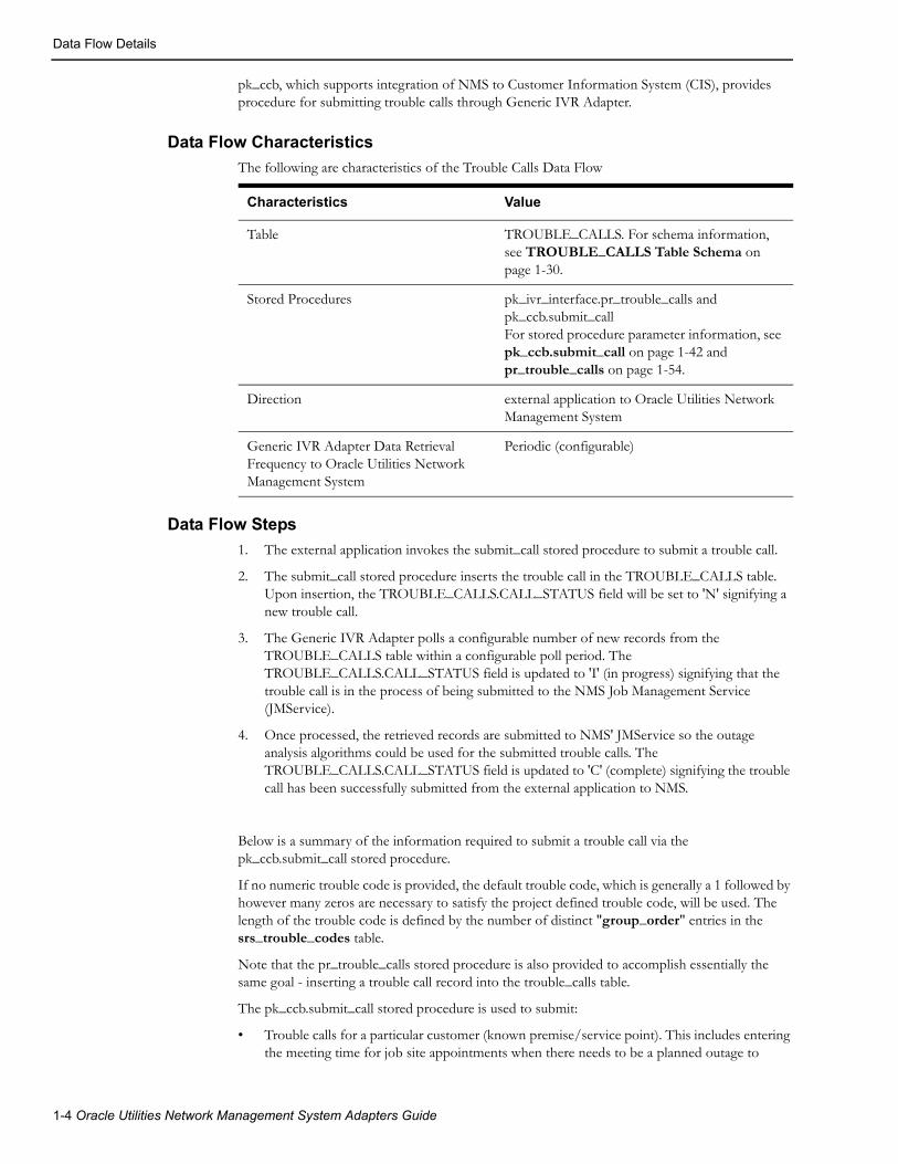
pk_ccb, which supports integration of NMS to Customer Information System (CIS), provides procedure for submitting trouble calls through Generic IVR Adapter.
Data Flow Characteristics
The following are characteristics of the Trouble Calls Data Flow
Characteristics Value
Table TROUBLE_CALLS. For schema information, see TROUBLE_CALLS Table Schema on page 1-30.
Stored Procedures pk_ivr_interface.pr_trouble_calls and pk_ccb.submit_callFor stored procedure parameter information, see pk_ccb.submit_call on page 1-42 and pr_trouble_calls on page 1-54.
Direction external application to Oracle Utilities Network Management System
Generic IVR Adapter Data Retrieval Frequency to Oracle Utilities Network Management System
Periodic (configurable)
Data Flow Steps
1. The external application invokes the submit_call stored procedure to submit a trouble call.
2. The submit_call stored procedure inserts the trouble call in the TROUBLE_CALLS table. Upon insertion, the TROUBLE_CALLS.CALL_STATUS field will be set to 'N' signifying a new trouble call.
3. The Generic IVR Adapter polls a configurable number of new records from the TROUBLE_CALLS table within a configurable poll period. The TROUBLE_CALLS.CALL_STATUS field is updated to 'I' (in progress) signifying that the trouble call is in the process of being submitted to the NMS Job Management Service (JMService).
4. Once processed, the retrieved records are submitted to NMS' JMService so the outage analysis algorithms could be used for the submitted trouble calls. The TROUBLE_CALLS.CALL_STATUS field is updated to 'C' (complete) signifying the trouble call has been successfully submitted from the external application to NMS.
Below is a summary of the information required to submit a trouble call via the pk_ccb.submit_call stored procedure.
If no numeric trouble code is provided, the default trouble code, which is generally a 1 followed by however many zeros are necessary to satisfy the project defined trouble code, will be used. The length of the trouble code is defined by the number of distinct "group_order" entries in the srs_trouble_codes table.
Note that the pr_trouble_calls stored procedure is also provided to accomplish essentially the same goal - inserting a trouble call record into the trouble_calls table.
The pk_ccb.submit_call stored procedure is used to submit:
• Trouble calls for a particular customer (known premise/service point). This includes entering the meeting time for job site appointments when there needs to be a planned outage to
1-4 Oracle Utilities Network Management System Adapters Guide
Data Flow Details
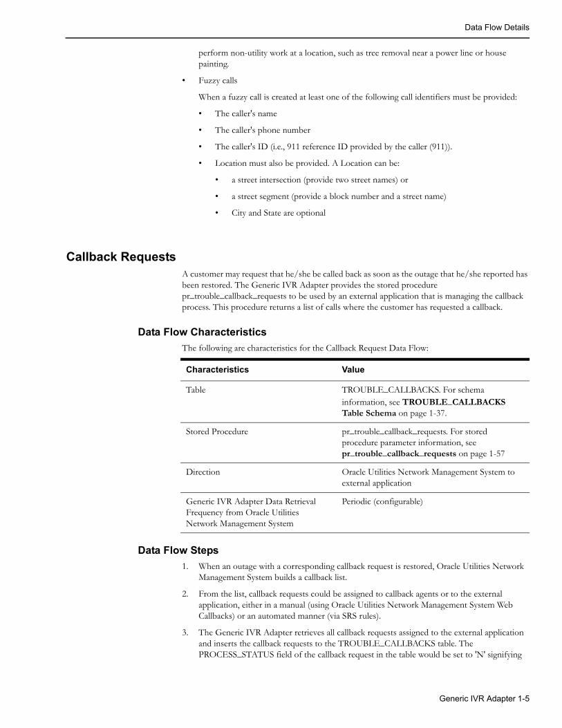
perform non-utility work at a location, such as tree removal near a power line or house painting.
• Fuzzy calls
When a fuzzy call is created at least one of the following call identifiers must be provided:
• The caller's name
• The caller's phone number
• The caller's ID (i.e., 911 reference ID provided by the caller (911)).
• Location must also be provided. A Location can be:
• a street intersection (provide two street names) or
• a street segment (provide a block number and a street name)
• City and State are optional
Callback RequestsA customer may request that he/she be called back as soon as the outage that he/she reported has been restored. The Generic IVR Adapter provides the stored procedure pr_trouble_callback_requests to be used by an external application that is managing the callback process. This procedure returns a list of calls where the customer has requested a callback.
Data Flow Characteristics
The following are characteristics for the Callback Request Data Flow:
Characteristics Value
Table TROUBLE_CALLBACKS. For schema information, see TROUBLE_CALLBACKS Table Schema on page 1-37.
Stored Procedure pr_trouble_callback_requests. For stored procedure parameter information, see pr_trouble_callback_requests on page 1-57
Direction Oracle Utilities Network Management System to external application
Generic IVR Adapter Data Retrieval Frequency from Oracle Utilities Network Management System
Periodic (configurable)
Data Flow Steps
1. When an outage with a corresponding callback request is restored, Oracle Utilities Network Management System builds a callback list.
2. From the list, callback requests could be assigned to callback agents or to the external application, either in a manual (using Oracle Utilities Network Management System Web Callbacks) or an automated manner (via SRS rules).
3. The Generic IVR Adapter retrieves all callback requests assigned to the external application and inserts the callback requests to the TROUBLE_CALLBACKS table. The PROCESS_STATUS field of the callback request in the table would be set to 'N' signifying
Generic IVR Adapter 1-5
Data Flow Details
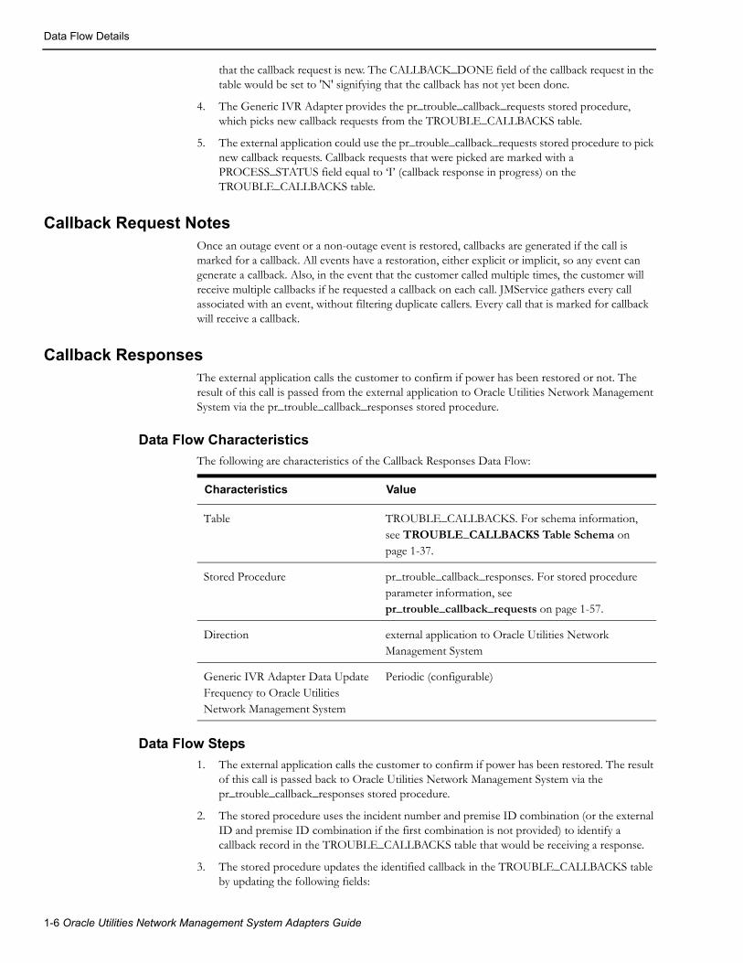
that the callback request is new. The CALLBACK_DONE field of the callback request in the table would be set to 'N' signifying that the callback has not yet been done.
4. The Generic IVR Adapter provides the pr_trouble_callback_requests stored procedure, which picks new callback requests from the TROUBLE_CALLBACKS table.
5. The external application could use the pr_trouble_callback_requests stored procedure to pick new callback requests. Callback requests that were picked are marked with a PROCESS_STATUS field equal to ‘I’ (callback response in progress) on the TROUBLE_CALLBACKS table.
Callback Request NotesOnce an outage event or a non-outage event is restored, callbacks are generated if the call is marked for a callback. All events have a restoration, either explicit or implicit, so any event can generate a callback. Also, in the event that the customer called multiple times, the customer will receive multiple callbacks if he requested a callback on each call. JMService gathers every call associated with an event, without filtering duplicate callers. Every call that is marked for callback will receive a callback.
Callback ResponsesThe external application calls the customer to confirm if power has been restored or not. The result of this call is passed from the external application to Oracle Utilities Network Management System via the pr_trouble_callback_responses stored procedure.
Data Flow Characteristics
The following are characteristics of the Callback Responses Data Flow:
Characteristics Value
Table TROUBLE_CALLBACKS. For schema information, see TROUBLE_CALLBACKS Table Schema on page 1-37.
Stored Procedure pr_trouble_callback_responses. For stored procedure parameter information, see pr_trouble_callback_requests on page 1-57.
Direction external application to Oracle Utilities Network Management System
Generic IVR Adapter Data Update Frequency to Oracle Utilities Network Management System
Periodic (configurable)
Data Flow Steps
1. The external application calls the customer to confirm if power has been restored. The result of this call is passed back to Oracle Utilities Network Management System via the pr_trouble_callback_responses stored procedure.
2. The stored procedure uses the incident number and premise ID combination (or the external ID and premise ID combination if the first combination is not provided) to identify a callback record in the TROUBLE_CALLBACKS table that would be receiving a response.
3. The stored procedure updates the identified callback in the TROUBLE_CALLBACKS table by updating the following fields:
1-6 Oracle Utilities Network Management System Adapters Guide
Adapter Installation
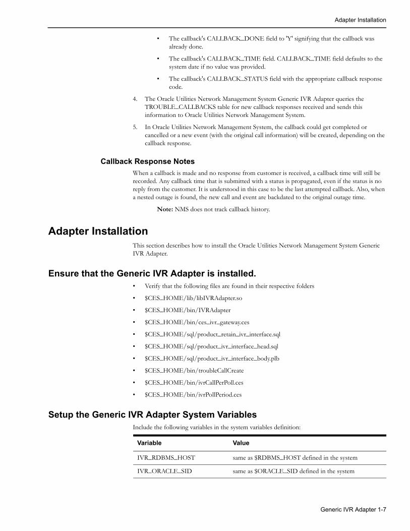
• The callback's CALLBACK_DONE field to 'Y' signifying that the callback was already done.
• The callback's CALLBACK_TIME field. CALLBACK_TIME field defaults to the system date if no value was provided.
• The callback's CALLBACK_STATUS field with the appropriate callback response code.
4. The Oracle Utilities Network Management System Generic IVR Adapter queries the TROUBLE_CALLBACKS table for new callback responses received and sends this information to Oracle Utilities Network Management System.
5. In Oracle Utilities Network Management System, the callback could get completed or cancelled or a new event (with the original call information) will be created, depending on the callback response.
Callback Response Notes
When a callback is made and no response from customer is received, a callback time will still be recorded. Any callback time that is submitted with a status is propagated, even if the status is no reply from the customer. It is understood in this case to be the last attempted callback. Also, when a nested outage is found, the new call and event are backdated to the original outage time.
Note: NMS does not track callback history.
Adapter InstallationThis section describes how to install the Oracle Utilities Network Management System Generic IVR Adapter.
Ensure that the Generic IVR Adapter is installed.• Verify that the following files are found in their respective folders
• $CES_HOME/lib/libIVRAdapter.so
• $CES_HOME/bin/IVRAdapter
• $CES_HOME/bin/ces_ivr_gateway.ces
• $CES_HOME/sql/product_retain_ivr_interface.sql
• $CES_HOME/sql/product_ivr_interface_head.sql
• $CES_HOME/sql/product_ivr_interface_body.plb
• $CES_HOME/bin/troubleCallCreate
• $CES_HOME/bin/ivrCallPerPoll.ces
• $CES_HOME/bin/ivrPollPeriod.ces
Setup the Generic IVR Adapter System VariablesInclude the following variables in the system variables definition:
Variable Value
IVR_RDBMS_HOST same as $RDBMS_HOST defined in the system
IVR_ORACLE_SID same as $ORACLE_SID defined in the system
Generic IVR Adapter 1-7

Adapter Installation
Note that this is setup in the .nmsrc file located in the $NMS_HOME (and configured by running config_nmsrc.pl). After the setup of the system variables, make sure that the .nmsrc is rerun or a new terminal is opened. The above setup assumes that the database where the Generic IVR Adapter tables and stored procedures would reside would be the same database used by the Oracle Utilities Network Management System environment.
Note also that the IVR RDBMS can be setup to be a completely separate RDBMS from the production RDBMS instance (hence these environment variables). This option may be considered if a project wants to maintain separation between the call taking process and the call processing process. With a separate RDBMS instance trouble calls can still be captured even if the production NMS RDBMS instance is down - for example. This is considered an advanced form of configuration and generally requires certain tables be replicated between the two RDBMS instances to guarantee calls can still be properly captured when the NMS RDBMS is down. Please consult Oracle support or your project engineer for more information if this type of configuration is desired.
Configure Adapter to run as NMS System ServiceConfigure the Generic IVR Adapter to run as an Oracle Utilities Network Management System service by updating the $NMS_HOME/etc/system.dat file to include the Generic IVR Adapter as a system service. There are 3 main sections where this service needs to be defined: the service, program and instance sections. See the $CES_HOME/templates/system.dat.template file for examples of how to configure the Generic IVR Adapter. Search for IVRAdapter in the file and copy those lines to $NMS_HOME/etc/system.dat file. Make sure all lines are uncommented so that they are active. You must restart the system services in order for the Generic IVR Adapter to be properly monitored by SMService. See the following section for details on command line options for the Generic IVR Adapter.
1-8 Oracle Utilities Network Management System Adapters Guide

Adapter Installation
IVRAdapter Command Line OptionsThe section below lists the possible command line options for the Generic IVR Adapter. This section also introduces a tool that randomly creates trouble calls, along with its command line options. Performance tuning and high-level diagnostic messages that could be used on the Generic IVR Adapter will be discussed in this section as well.
The Generic IVR Adapter provides various command line options that enables Data Flows and configures Data Flow behavior. The following enumerates the command line options of the Generic IVR Adapter.
IVRAdapter -help -troublecall -omscbreq -omscbresp -cleantable -debug [0-2] -callperpoll NUMBERCALLS -pollperiod SECONDS -docustquery -cbreqinterval SECONDS -cbrespinterval SECONDS -cleaninterval HOURS -keepdbinfo DAYS -cbagent AGENTNAME [ -cbAny | -cbLast ]
This section groups the Generic IVR Adapter command line options under the context of the Data Flow or Data Flows it is associated to.
Generic IVR Adapter Generic Command Line Options
The following are the Generic IVR Adapter command line options that are independent from any Data Flow:
Option Usage Description
help IVRAdapter -help Displays the available command line options
debug IVRAdapter -debug LEVEL(where LEVEL is 0, 1 or 2)
Runs gateway in debug mode. Associated number represents the debug level range from 0 to 2.
Generic IVR Adapter 1-9

Adapter Installation
Trouble Call Data Flow Command Line Options
The following are the Generic IVR Adapter command line options that are related to the Trouble Calls Data Flow. For more information, see Trouble Calls on page 1-3.
Option Usage DescriptionDepends On
Default Value
troublecall IVRAdapter -troublecall
Enables the Trouble Calls Data Flow.Note: This option must be enabled for CC&B - NMS integration.
callperpoll IVRAdapter -callperpoll NUMBERCALLS(where NUMBERCALLS is an integer)
Specifies the number of calls processed in the TROUBLE_CALLS table per poll of information.
troublecall 100 calls per poll of information
pollperiod IVRAdapter -pollperiod SECONDS(where SECONDS is an integer)
Specifies the interval (in seconds) between two successive polls or queries from the TROUBLE_CALLS table
troublecall a 6 second interval between two successive polls
docustquery IVRAdapter -docustquery
If this option is selected, not all fields in the TROUBLE_CALLS table are directly fed to JMService. Instead, some of the fields would come from the CES_CUSTOMERS table. Note: This option should not be used in combination with the CC&B - NMS integration.
troublecall
1-10 Oracle Utilities Network Management System Adapters Guide

Adapter Installation
Callback Requests Data Flow Command Line Options
The following are the Generic IVR Adapter command line options that are related to the Callback Requests Data Flow. For more information, see Callback Requests on page 1-5.
Option Usage DescriptionDepends On
Default Value
omscbreq IVRAdapter -omscbreq Enables the Callback Requests Data Flow
cbreqinterval IVRAdapter -cbreqinterval SECONDS(where SECONDS is an integer)
Specifies the interval (in seconds) between two successive polls from the list of callback requests
omscbreq a 5 second interval between two successive polls.
cbAny IVRAdapter -cbAny Callback is submitted to IVR if requested by the customer during any call.
omscbreq
cbLast IVRAdapter -cbLast Callback is submitted to IVR if requested by the customer during the last call.
omscbreq
Generic IVR Adapter 1-11

Adapter Installation
Callback Responses Data Flow Command Line Options
The following are the Generic IVR Adapter command line options that are related to the Callback Responses Data Flow. For more information, see Callback Responses on page 1-6.
Option Usage DescriptionDepends On
Default Value
omscbresp IVRAdapter -omscbresp
Enables the Callback Responses Data Flow
cbrespinterval IVRAdapter -cbrespinterval SECONDS(where SECONDS is an integer)
Specifies the interval (in seconds) between two successive polls from the TROUBLE_CALLBACKS table for received callback responses
omscbresp a 5 second interval between two successive polls.
Command Line Options Used by Multiple Data Flows
The following are the Generic IVR Adapter command line options that are related to multiple Data Flows. On the ‘Depends On’ section, the term ‘any option that enables a Data Flow’ would pertain to either one of the following command line options: ‘troublecall’, ‘omscbreq’ and ‘omscbresp’.
Option Usage DescriptionDepends On
Default Value
cleantable IVRAdapter -cleantable
Could be used for any of the five Data Flows. A flag that allows the Generic IVR Adapter to remove some completed records from its tables.
any option that enables a Data Flow
cleaninterval IVRAdapter -cleaninterval HOURS(where HOURS is an integer)
Could be used for any of the five Data Flows.Specifies the interval (in HOURS) between two successive attempts to delete old (i.e., completed) records from the Oracle Utilities Network Management System Generic IVR Adapter tables.
Cleantable and any option that enables a Data Flow
1 hour between to successive delete attempts
keepdbinfo IVRAdapter -keepdbinfo DAYS(where DAYS is an integer)
Could be used for any of the five Data Flows.Completed records on the Generic IVR Adapter tables older than the specified number of days will be deleted. Certain criteria apply on which records of the Oracle Utilities Network Management System Generic IVR Adapter tables are removed and how the records are aged.
Cleantable and any option that enables a Data Flow
3 days
1-12 Oracle Utilities Network Management System Adapters Guide

Adapter Installation
For the keepdbinfo command line options, a record that starts aging on a given day, say 9:00 p.m. would be considered one day old at 9:00 p.m. the next day (and not 12:00 a.m., which is just 3 hours from the time the record started aging).
troubleCallCreate Tool Command Line Options
Random trouble calls could be created and passed to the Generic IVR Adapter using the troubleCallCreate tool. The troubleCallCreate tool inserts entries to the TROUBLE_CALLS table. From here, the Generic IVR Adapter (through the Trouble Calls Data Flow) could fetch the new records from this table and pass this information to Oracle Utilities Network Management System, so Oracle Utilities Network Management System could apply the outage analysis algorithm to predict the outage device.
Note: It is important for the Generic IVR Adapter System Variables to be setup to run the troubleCallCreate tool. For more information, see Setup the Generic IVR Adapter System Variables.
The following are the command line options for the troubleCallCreate tool:
Option Usage Description Default Value
help troubleCallCreate –help Displays the available command line options
debug troubleCallCreate -debug Runs this tool in debug mode, defaulting the debug level to 2.
Defaults to debug level 2
totalcalls troubleCallCreate –totalcalls NUMBEROFCALLS
(where NUMBEROFCALLS is an integer)
Specifies the number of trouble calls to be created
troublecall troubleCallCreate –troublecall
Creates one trouble call
cbagent IVRAdapter –cbagent AGENTNAME (where AGENTNAME is a string)
Could be used for the Callback Requests and Callback Responses Data Flows.The agent name that the Generic IVR Adapter uses in retrieving calls from the callback list. Valid agent names are located in CES_USER and ENV_ACCESS tables. The agent name used should be an external agent, as indicated in the CES_USER table.
omscbreq or omscbresp
IVR
Option Usage DescriptionDepends On
Default Value
Generic IVR Adapter 1-13

Adapter Installation
troubleCallCreate tool on testing Trouble Calls Data Flow
As the troubleCallCreate tool randomly creates trouble calls, this tool could be used to test the Trouble Calls Data Flow. For more information about this Data Flow, see Trouble Calls on page 1-3.
The troubleCallCreate tool uses the CES_CUSTOMERS table to retrieve some customer information that would be used as entries in the TROUBLE_CALLS table. The tool always begins querying the CES_CUSTOMERS table starting from the first row, each time it is invoked.
When multiple trouble calls would be created (using the ‘totalcalls’ command line option), the troubleCallCreate tool would place a different permutation of trouble code bits for each trouble call in the TROUBLE_CALLS table.
After running the troubleCallCreate tool, the results could be verified using the following database tables:
• The TR OUBLE_CALLS table is populated with a new trouble call record (or with a certain number of trouble calls, assuming that the ‘totalcalls’ command line option was used).
• As the Generic IVR Adapter runs (using the Trouble Calls Data Flow), the INCIDENTS table is populated with new records.
Note: The number of new records in the INCIDENTS table is less than or equal to the total number of new trouble calls in the TROUBLE_CALLS table, as Oracle Utilities Network Management System outage analysis algorithms allow grouping of calls based on various criteria.
troubleCallCreate tool on testing Callback Requests Data Flow
The Callback Requests Data Flow could be tested as well using the troubleCallCreate tool, since all trouble calls generated by such tool requires callback. For more information about this Data Flow, see Data Flow Details on page 1-3.
• For a generated trouble call, if part of the trouble code is described to be 'Power On', no record in the TROUBLE_CALLBACKS table will be generated even if the event is restored.
1-14 Oracle Utilities Network Management System Adapters Guide
Adapter Installation
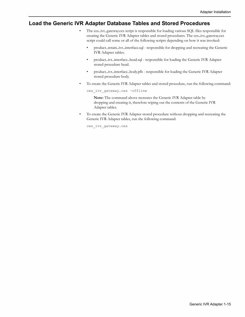
Load the Generic IVR Adapter Database Tables and Stored Procedures• The ces_ivr_gateway.ces script is responsible for loading various SQL files responsible for
creating the Generic IVR Adapter tables and stored procedures. The ces_ivr_gateway.ces script could call some or all of the following scripts depending on how it was invoked:
• product_retain_ivr_interface.sql - responsible for dropping and recreating the Generic IVR Adapter tables.
• product_ivr_interface_head.sql - responsible for loading the Generic IVR Adapter stored procedure head.
• product_ivr_interface_body.plb - responsible for loading the Generic IVR Adapter stored procedure body.
• To create the Generic IVR Adapter tables and stored procedure, run the following command:
ces_ivr_gateway.ces –offline
Note: The command above recreates the Generic IVR Adapter table by dropping and creating it, therefore wiping out the contents of the Generic IVR Adapter tables.
• To create the Generic IVR Adapter stored procedure without dropping and recreating the Generic IVR Adapter tables, run the following command:
ces_ivr_gateway.ces
Generic IVR Adapter 1-15
Software Configuration
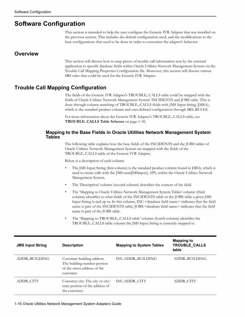
Software ConfigurationThis section is intended to help the user configure the Generic IVR Adapter that was installed on the previous section. This includes the default configuration used, and the modifications to the base configurations that need to be done in order to customize the adapter's behavior.
OverviewThis section will discuss how to map pieces of trouble call information sent by the external application to specific database fields within Oracle Utilities Network Management System via the Trouble Call Mapping Properties Configuration file. Moreover, this section will discuss various SRS rules that could be used for the Generic IVR Adapter.
Trouble Call Mapping ConfigurationThe fields of the Generic IVR Adapter's TROUBLE_CALLS table could be mapped with the fields of Oracle Utilities Network Management System' INCIDENTS and JOBS table. This is done through column matching of TROUBLE_CALLS fields with JMS Input String (JMS.h), which is the standard product column and user-defined configuration through SRS_RULES.
For more information about the Generic IVR Adapter's TROUBLE_CALLS table, see TROUBLE_CALLS Table Schema on page 1-30.
Mapping to the Base Fields in Oracle Utilities Network Management System Tables
The following table explains how the base fields of the INCIDENTS and the JOBS tables of Oracle Utilities Network Management System are mapped with the fields of the TROUBLE_CALLS table of the Generic IVR Adapter.
Below is a description of each column
• The JMS Input String (first column) is the standard product column found in JMS.h, which is used to create calls with the JMS::sendJMSinput() API, within the Oracle Utilities Network Management System.
• The ‘Description’ column (second column) describes the content of the field.
• The ‘Mapping to Oracle Utilities Network Management System Tables’ column (third column) identifies to what fields of the INCIDENTS table or the JOBS table a given JMS Input String is tied up to. In this column, INC.<database field name> indicates that the field name is part of the INCIDENTS table; JOBS.<database field name> indicates that the field name is part of the JOBS table.
• The ‘Mapping to TROUBLE_CALLS table’ column (fourth column) identifies the TROUBLE_CALLS table column the JMS Input String is currently mapped to.
JMS Input String Description Mapping to System TablesMapping to TROUBLE_CALLS table
ADDR_BUILDING Customer building address. The building number portion of the street address of the customer.
INC.ADDR_BUILDING ADDR_BUILDING
ADDR_CITY Customer city. The city or city/state portion of the address of the customer.
INC.ADDR_CITY ADDR_CITY
1-16 Oracle Utilities Network Management System Adapters Guide

Software Configuration
ADDR_CROSS_STREET
Intersection cross street name. Name of the second cross street should be in ADDR_STREET field.
INC.ADDR_CROSS_STREET ADDR_CROSS_STREET
ADDR_STREET Customer street address. The full street address of the customer.
INC.ADDRESSJOBS.ADDR_STREET
ADDR_STREET
ALTERNATE_PHONE Alternative contact number. Alternate phone number for contacting the customer.
INC.ALTERNATE_PHONE ALTERNATE_PHONE
APPT_RANGE Appointment Range. INC.APPT_RANGE APPT_RANGE
APPT_TIME Time of appointment. INC.APPT_TIME APPT_TIME
APPT_TYPE Type of appointment. INC.APPT_TYPE APPT_TYPE
CALL_TIME Input time of call. The input time of the incident. If not provided, the current time will be used.
INC.INPUT_TIME CALL_TIME
CALL_TYPE Type of call. INC.TYPE CALL_TYPE
CALLBACK_LATE Callback late indicator. Indicates that it is OK to call back the customer beyond a defined ‘late’ time. This information is only stored in Oracle Utilities Network Management System. No other action is taken by Oracle Utilities Network Management System.
INC.CALLBACK_LATE CALLBACK_LATE
CALLBACK_REQUEST Indicates either a callback is requested or not.
INC.CALLBACK_REQUEST CALLBACK_REQUEST
CALLBACK_TIME Time callback requested. Time for which callback or a follow-up call was requested.
INC.CALLBACK_TIME CALLBACK_TIME
CHECK_CUTOFF Check cutoff customer indicator. If set to Y, check if the customer is disconnected, using the CES_DISCONNECTS table. If the customer is disconnected, the call will not be saved, an error will be returned and the VERIFY_DISCONNECTS table will be populated.
CHECK_CUTOFF
JMS Input String Description Mapping to System TablesMapping to TROUBLE_CALLS table
Generic IVR Adapter 1-17

Software Configuration
CID_ALIAS Not used. CID_ALIAS
CLUE Indicates if call is clue if set to Y.
INC.CLUE CLUE
COMBINE_PRI Total priority of call. COMBINE_PRI
COMMENT Call-taker Comments. Comments provided by the customer or call-taker about the incident.
INC.OP_COMMENT CALL_COMMENT
CUST_CALL_CANCEL Call cancel indicator. INC.CALL_CANCEL CUST_CALL_CANCEL
CUST_CRITICAL Critical customer indicator. This is added to the critical C count of the outage.
INC.CRITICAL_CUST CUST_CRITICAL
CUST_DEVICE_ALIAS The name of the device to which the customer is connected. This must be the alias of the device handle provided with CUST_DEVICE_CLS and CUST_DEVICE_IDX. If not provided, the service will query ODService to get this information, incurring a performance penalty in call processing.
INC.OBJECT CUST_DEVICE_ALIAS
CUST_DEVICE_CLS Customer device class. The class part of the handle for the device to which the customer is connected. If CUST_ID is provided, but the device is not, JMService will look up the customer device in the CES_CUSTOMERS table. If the provided device is a supply node, it will be put in SUPPLY_CLS & SUPPLY_IDX and the first stage device will be put in H_CLS & H_IDX.
INC.H_CLS CUST_DEVICE_CLS
CUST_DEVICE_IDX Customer device index. The index part of the handle for the device to which the customer is connected. See CUST_DEVICE_CLS above.
INC.H_IDX CUST_DEVICE_IDX
CUST_DEVICE_NCG NCG of customer device. INC.NCG CUST_DEVICE_NCG
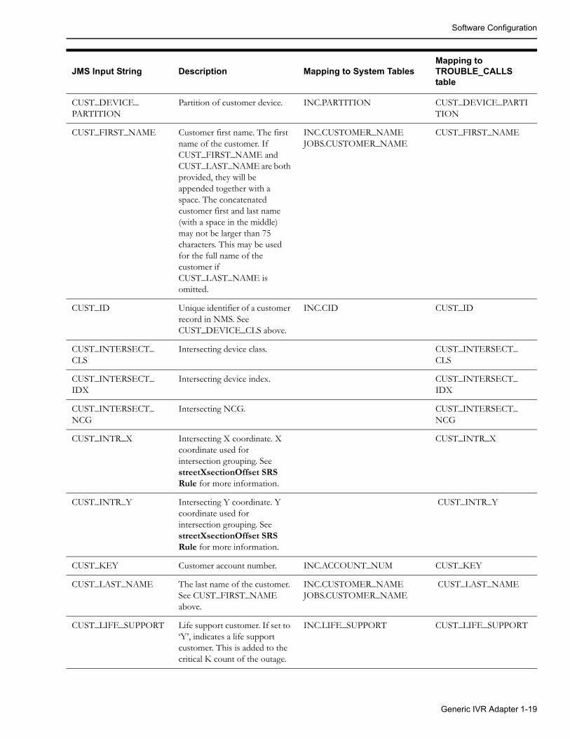
JMS Input String Description Mapping to System TablesMapping to TROUBLE_CALLS table
1-18 Oracle Utilities Network Management System Adapters Guide
Software Configuration
CUST_DEVICE_PARTITION
Partition of customer device. INC.PARTITION CUST_DEVICE_PARTITION
CUST_FIRST_NAME Customer first name. The first name of the customer. If CUST_FIRST_NAME and CUST_LAST_NAME are both provided, they will be appended together with a space. The concatenated customer first and last name (with a space in the middle) may not be larger than 75 characters. This may be used for the full name of the customer if CUST_LAST_NAME is omitted.
INC.CUSTOMER_NAMEJOBS.CUSTOMER_NAME
CUST_FIRST_NAME
CUST_ID Unique identifier of a customer record in NMS. See CUST_DEVICE_CLS above.
INC.CID CUST_ID
CUST_INTERSECT_CLS
Intersecting device class. CUST_INTERSECT_CLS
CUST_INTERSECT_IDX
Intersecting device index. CUST_INTERSECT_IDX
CUST_INTERSECT_NCG
Intersecting NCG. CUST_INTERSECT_NCG
CUST_INTR_X Intersecting X coordinate. X coordinate used for intersection grouping. See streetXsectionOffset SRS Rule for more information.
CUST_INTR_X
CUST_INTR_Y Intersecting Y coordinate. Y coordinate used for intersection grouping. See streetXsectionOffset SRS Rule for more information.
CUST_INTR_Y
CUST_KEY Customer account number. INC.ACCOUNT_NUM CUST_KEY
CUST_LAST_NAME The last name of the customer. See CUST_FIRST_NAME above.
INC.CUSTOMER_NAMEJOBS.CUSTOMER_NAME
CUST_LAST_NAME
CUST_LIFE_SUPPORT Life support customer. If set to ‘Y’, indicates a life support customer. This is added to the critical K count of the outage.
INC.LIFE_SUPPORT CUST_LIFE_SUPPORT
JMS Input String Description Mapping to System TablesMapping to TROUBLE_CALLS table
Generic IVR Adapter 1-19
Software Configuration
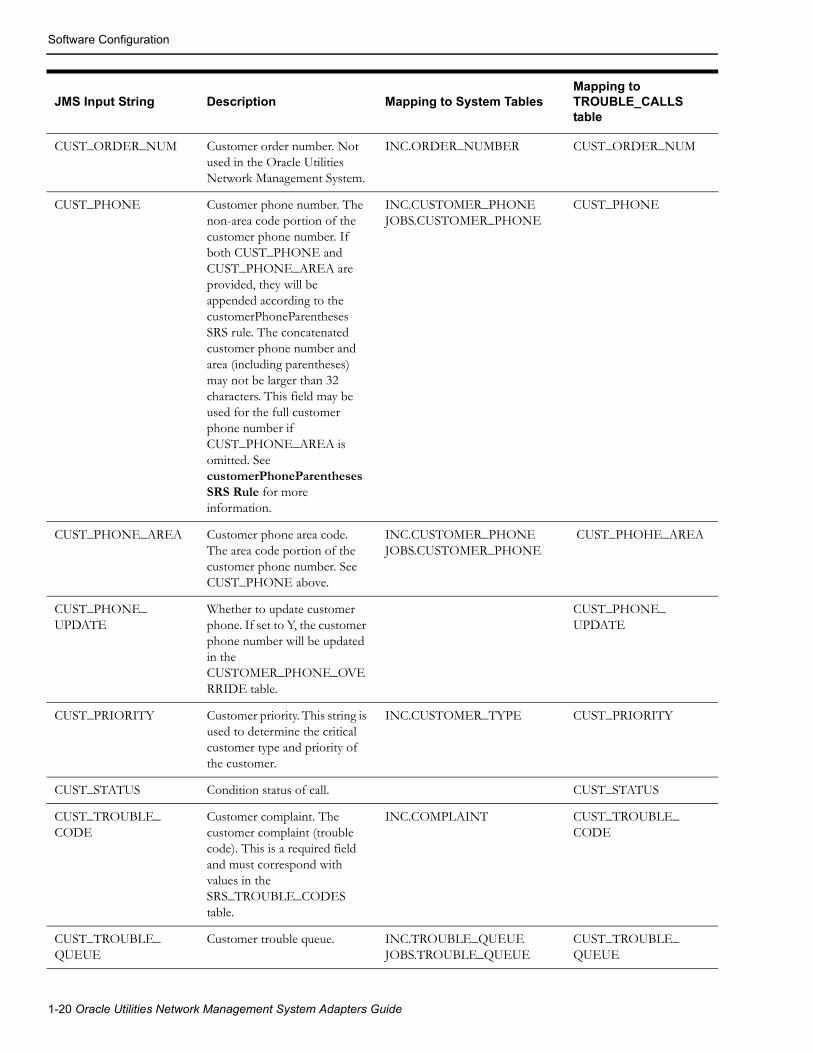
CUST_ORDER_NUM Customer order number. Not used in the Oracle Utilities Network Management System.
INC.ORDER_NUMBER CUST_ORDER_NUM
CUST_PHONE Customer phone number. The non-area code portion of the customer phone number. If both CUST_PHONE and CUST_PHONE_AREA are provided, they will be appended according to the customerPhoneParentheses SRS rule. The concatenated customer phone number and area (including parentheses) may not be larger than 32 characters. This field may be used for the full customer phone number if CUST_PHONE_AREA is omitted. See customerPhoneParentheses SRS Rule for more information.
INC.CUSTOMER_PHONEJOBS.CUSTOMER_PHONE
CUST_PHONE
CUST_PHONE_AREA Customer phone area code. The area code portion of the customer phone number. See CUST_PHONE above.
INC.CUSTOMER_PHONEJOBS.CUSTOMER_PHONE
CUST_PHOHE_AREA
CUST_PHONE_UPDATE
Whether to update customer phone. If set to Y, the customer phone number will be updated in the CUSTOMER_PHONE_OVERRIDE table.
CUST_PHONE_UPDATE
CUST_PRIORITY Customer priority. This string is used to determine the critical customer type and priority of the customer.
INC.CUSTOMER_TYPE CUST_PRIORITY
CUST_STATUS Condition status of call. CUST_STATUS
CUST_TROUBLE_CODE
Customer complaint. The customer complaint (trouble code). This is a required field and must correspond with values in the SRS_TROUBLE_CODES table.
INC.COMPLAINT CUST_TROUBLE_CODE
CUST_TROUBLE_QUEUE
Customer trouble queue. INC.TROUBLE_QUEUEJOBS.TROUBLE_QUEUE
CUST_TROUBLE_QUEUE
JMS Input String Description Mapping to System TablesMapping to TROUBLE_CALLS table
1-20 Oracle Utilities Network Management System Adapters Guide
Software Configuration
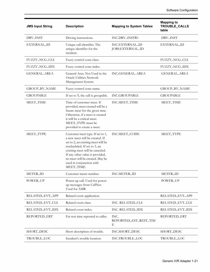
DRV_INST Driving instructions. INC.DRV_INSTR1 DRV_INST
EXTERNAL_ID Unique call identifier. The unique identifier for the incident.
INC.EXTERNAL_IDJOBS.EXTERNAL_ID
EXTERNAL_ID
FUZZY_NCG_CLS Fuzzy control zone class. FUZZY_NCG_CLS
FUZZY_NCG_IDX Fuzzy control zone index. FUZZY_NCG_IDX
GENERAL_AREA General Area. Not Used in the Oracle Utilities Network Management System.
INC.GENERAL_AREA GENERAL_AREA
GROUP_BY_NAME Fuzzy control zone name. GROUP_BY_NAME
GROUPABLE If set to Y, the call is groupable. INC.GROUPABLE GROUPABLE
MEET_TIME Time of customer meet. If provided, meet created will be a future meet for the given time. Otherwise, if a meet is created it will be a critical meet. MEET_TYPE must be provided to create a meet.
INC.MEET_TIME MEET_TIME
MEET_TYPE Customer meet type. If set to 1, a new meet will be created. If set to 2, an existing meet will be rescheduled. If set to 3, an existing meet will be canceled. If any other value is provided, no meet will be created. May be used in conjunction with MEET_TIME.
INC.MEET_CODE MEET_TYPE
METER_ID Customer meter number. INC.METER_ID METER_ID
POWER_UP Power-up call. Used for power-up messages from CellNet. Used for AMR.
POWER_UP
RELATED_EVT_APP Related event application. RELATED_EVT_APP
RELATED_EVT_CLS Related event class. INC. RELATED_CLS RELATED_EVT_CLS
RELATED_EVT_IDX Related event index. INC. RELATED_IDX RELATED_EVT_IDX
REPORTED_ERT Est rest time reported to caller. INC. REPORTED_EST_REST_TIME
REPORTED_ERT
SHORT_DESC Short description of trouble. INC.SHORT_DESC SHORT_DESC
TROUBLE_LOC Incident's trouble location. INC.TROUBLE_LOC TROUBLE_LOC
JMS Input String Description Mapping to System TablesMapping to TROUBLE_CALLS table
Generic IVR Adapter 1-21
Software Configuration
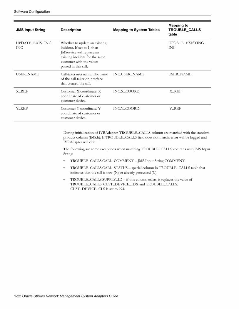
During initialization of IVRAdapter, TROUBLE_CALLS column are matched with the standard product column (JMS.h). If TROUBLE_CALLS field does not match, error will be logged and IVRAdapter will exit.
The following are some exceptions when matching TROUBLE_CALLS columns with JMS Input String:
• TROUBLE_CALLS.CALL_COMMENT – JMS Input String COMMENT
• TROUBLE_CALLS.CALL_STATUS – special column in TROUBLE_CALLS table that indicates that the call is new (N) or already processed (C).
• TROUBLE_CALLS.SUPPLY_ID – if this column exists, it replaces the value of TROUBLE_CALLS. CUST_DEVICE_IDX and TROUBLE_CALLS. CUST_DEVICE_CLS is set to 994.
UPDATE_EXISTING_INC
Whether to update an existing incident. If set to 1, then JMService will replace an existing incident for the same customer with the values passed in this call.
UPDATE_EXISTING_INC
USER_NAME Call-taker user name. The name of the call-taker or interface that created the call.
INC.USER_NAME USER_NAME
X_REF Customer X coordinate. X coordinate of customer or customer device.
INC.X_COORD X_REF
Y_REF Customer Y coordinate. Y coordinate of customer or customer device.
INC.Y_COORD Y_REF
JMS Input String Description Mapping to System TablesMapping to TROUBLE_CALLS table
1-22 Oracle Utilities Network Management System Adapters Guide

Trouble Callback Mapping Configuration
Mapping to Customer-Defined Fields in Oracle Utilities Network Management System's INCIDENTS table
A configurable TROUBLE_CALLS column can also be done through SRS_RULES.
The following are the steps to map a new field in the TROUBLE_CALLS table with a new field in the INCIDENTS table:
1. Change the TROUBLE_CALLS table schema to include the customized field, for instance, TC_FIELD_ONE.
2. Change the INCIDENTS table schema to include a new field that will be mapped to TC_FIELD_ONE. For instance the new field on the INCIDENTS table would be INC_FIELD_ONE.
3. Create a new SRS Rule that maps the ‘201’ (TROUBLE_CALLS reserve name) with the new field in the INCIDENTS table, INC_FIELD_ONE. See the Map Customer-Defined Fields in the INCIDENTS Table on page 1-24 SRS rule for more information.
4. Restart JMService and the Generic IVR Adapter.
Note: Before considering the option of introducing new fields in the TROUBLE_CALLS table and the INCIDENTS table, it is advisable to discuss such option with your Project Engineer.
Trouble Callback Mapping ConfigurationIVR Adapter allows arbitrary information from the PICKLIST_INFO_UPD_TR table to be included into callback request. Columns CB_DETAIL1, CB_DETAIL2, CB_DETAIL3 and CB_DETAIL4 in the TROUBLE_CALLBACKS database table are used for this purpose. Database table IVR_ADAPTER_CONFIG is used to define if/how these columns should be populated.
Field Name Nullable Data Type Description
CONFIG_ITEM N VARCHAR2(32) Column name in the TROUBLE_CALLBACKS database table, which should be populated from the PICKLIST_INFO_UPD_TR table. Valid values are
CONFIG_VALUE N VARCHAR2(32) Column name in the PICKLIST_INFO_UPD_TR table, which should be used as the data source.
Generic IVR Adapter 1-23

SRS Rules Configuration
SRS Rules ConfigurationThe following are SRS rules that could be used with the Generic IVR Adapter. These SRS rules can be included in the <project>_srs_rules.sql file.
Map Customer-Defined Fields in the INCIDENTS TableOracle Utilities Network Management System and the Generic IVR Adapter provides a mechanism to receive additional trouble call information from the external application and have this information stored in a new customer-defined field in the INCIDENTS table of Oracle Utilities Network Management System.
The configurable TROUBLE_CALLS column name has special names ‘201’, ‘202’, up to ‘209’ to serve this purpose. Normally, a regular column name in TROUBLE_CALLS like CALL_COMMENT or COMMENT in JMS Input String is tied to a specific field of the INCIDENTS table by default. For this case, it's the OP_COMMENT field. A special name like ‘201’ could be mapped to a new field in the INCIDENTS table by using an SRS rule. The table below details how an SRS rule could be used to do this mapping. An SRS rule like this has to be used for each mapping. See Map Customer-Defined Fields in the INCIDENTS Table on page 1-24 for more information.
Field Name Value
SET_NAME ‘config_incident’
INCIDENT_TYPE ‘customer_defined’
RULE_NAME the name of the new column in the INCIDENTS table
RULE_VALUE_1 ‘str’, ‘date’, ‘int’, ‘float’‘str’ is for strings, ‘date’ is for dates, ‘int’ is for integers, and ‘float’ is for floats. This represents the data type of the new column.
RULE_VALUE_2 An integer, representing the value of the SRS input configuration item specifying this field -- must have a value of 200 or greater
RULE_VALUE_INTEGER_1 0 (not used)
RULE_VALUE_INTEGER_2 0 (not used)
RULE_VALUE_INTEGER_3 0 (not used)
RULE_VALUE_INTEGER_4 0 (not used)
RULE_VALUE_INTEGER_5 0 (not used)
1-24 Oracle Utilities Network Management System Adapters Guide

SRS Rules Configuration
callbackInterfaceEnabled SRS RuleIf set to ‘yes’ then SRS APIs for manipulating callback information will become available. It has to be set to ‘yes’ for Web Callback GUI to operate. This rule holds outage information in JMService memory on a special data structure until this time expires OR all customer callbacks for the outage are complete.
Field Name Value
SET_NAME ‘config’
INCIDENT_TYPE ‘any’
RULE_VALUE_1 ‘yes’ or ‘no’ (default: ‘no’)
RULE_VALUE_2 0 (not used)
RULE_VALUE_INTEGER_1 0 (not used)
RULE_VALUE_INTEGER_2 0 (not used)
RULE_VALUE_INTEGER_3 0 (not used)
RULE_VALUE_INTEGER_4 0 (not used)
RULE_VALUE_INTEGER_5 0 (not used)
Generic IVR Adapter 1-25

SRS Rules Configuration
useExternalCause SRS RuleIf set to ‘yes’ then the IVR Adapter’s callback requests data flow will include the cause code when it populates the TROUBLE_CALLBACKS table. The cause code value will be taken from JOBS.CAUSE.
Field Name Value
SET_NAME ‘config’
INCIDENT_TYPE ‘any’
RULE_VALUE_1 ‘yes’ or ‘no’ (default: ‘yes’)
RULE_VALUE_2 0 (not used)
RULE_VALUE_INTEGER_1 0 (not used)
RULE_VALUE_INTEGER_2 0 (not used)
RULE_VALUE_INTEGER_3 0 (not used)
RULE_VALUE_INTEGER_4 0 (not used)
RULE_VALUE_INTEGER_5 0 (not used)
customerPhoneParentheses SRS RuleIf rule_value_1 set to ‘yes’, parentheses will be added to customer call phone numbers in the following format: (AREA)NUMBER. Otherwise, the number and area will be concatenated together without parentheses.
Field Name Value
SET_NAME ‘config’
INCIDENT_TYPE ‘any’
RULE_VALUE_1 ‘yes’ or ‘no’ (Default: ‘yes’)
RULE_VALUE_2 0 (not used)
RULE_VALUE_INTEGER_1 0 (not used)
RULE_VALUE_INTEGER_2 0 (not used)
RULE_VALUE_INTEGER_3 0 (not used)
RULE_VALUE_INTEGER_4 0 (not used)
RULE_VALUE_INTEGER_5 0 (not used)
1-26 Oracle Utilities Network Management System Adapters Guide

SRS Rules Configuration
defaultCallbackAgent SRS RuleSpecifies username of the default callback agent. All new callbacks will be automatically assigned to this agent. If this rule is not set then new callbacks will be left unassigned.
Note: This rule only takes effect if the rule callbackInterfaceEnabled set to ‘yes’. See callbackInterfaceEnabled SRS Rule on page 1-25 for more information. The agent name used should be considered as an external agent in the CES_USER and ENV_ACCESS tables. Also, it is recommended that ‘IVR’ be used as a value of RULE_VALUE_1, as this is the default callback agent name that the Generic IVR Adapter uses when the adapter runs.
callbackFeederTimeout SRS RuleThe maximum time allowed (in minutes) between the current time and the restoration time of a resolution in callback module before the resolution is deemed too old to remain or be loaded into the callback module. This rule holds outage info in JMService memory in a special data structure until this time expires OR all customer callbacks for the outage are complete.
If this rule is set to 0 then resolutions will be kept in JMService until all callbacks are completed.
Note: This rule must be used in conjunction with the callbackInterfaceEnabled SRS Rule on page 1-25.
Field Name Value
SET_NAME ‘config’
INCIDENT_TYPE ‘any’
RULE_VALUE_1 callback agent username
RULE_VALUE_2 0 (not used)
RULE_VALUE_INTEGER_1 0 (not used)
RULE_VALUE_INTEGER_2 0 (not used)
RULE_VALUE_INTEGER_3 0 (not used)
RULE_VALUE_INTEGER_4 0 (not used)
RULE_VALUE_INTEGER_5 0 (not used)
Field Name Value
INCIDENT_TYPE ‘flowControlGeneral’
RULE_VALUE_1 "" (not used)
RULE_VALUE_2An integer, representing a number of minutes (Default: 2880 -- 48 hours)
RULE_VALUE_INTEGER_1 0 (not used)
RULE_VALUE_INTEGER_2 0 (not used)
RULE_VALUE_INTEGER_3 0 (not used)
Generic IVR Adapter 1-27
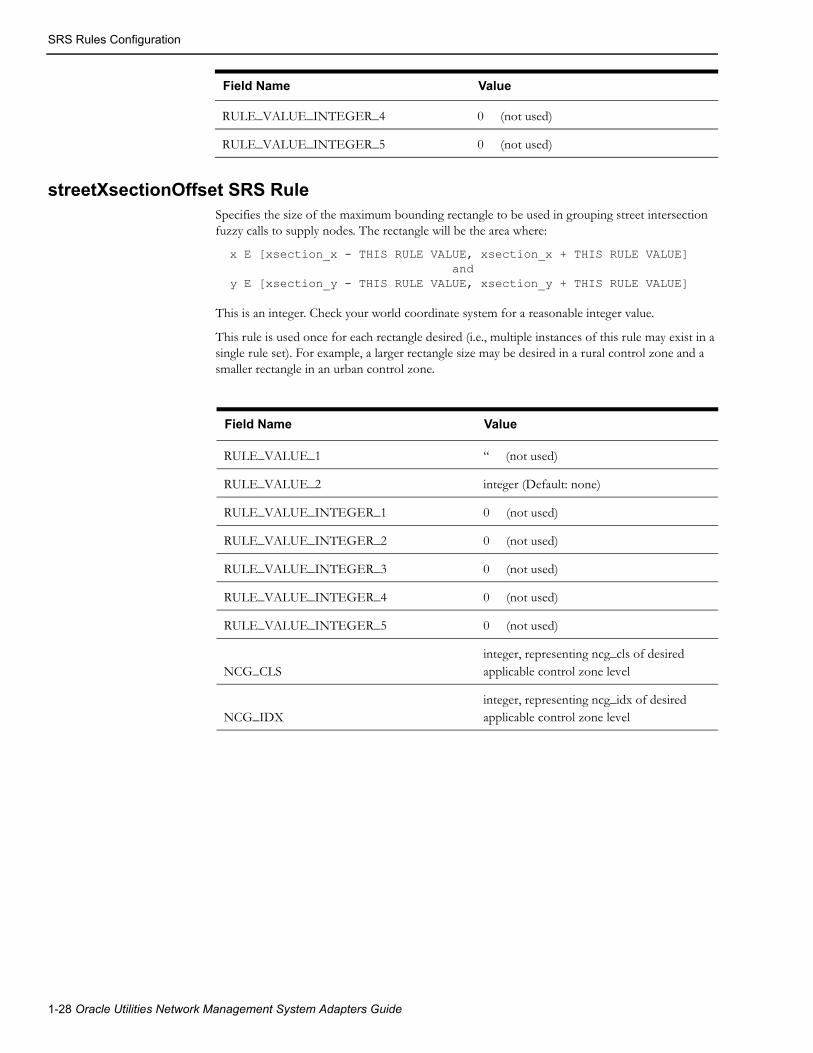
SRS Rules Configuration
streetXsectionOffset SRS RuleSpecifies the size of the maximum bounding rectangle to be used in grouping street intersection fuzzy calls to supply nodes. The rectangle will be the area where:
x E [xsection_x - THIS RULE VALUE, xsection_x + THIS RULE VALUE] and y E [xsection_y - THIS RULE VALUE, xsection_y + THIS RULE VALUE]
This is an integer. Check your world coordinate system for a reasonable integer value.
This rule is used once for each rectangle desired (i.e., multiple instances of this rule may exist in a single rule set). For example, a larger rectangle size may be desired in a rural control zone and a smaller rectangle in an urban control zone.
Field Name Value
RULE_VALUE_1 ‘‘ (not used)
RULE_VALUE_2 integer (Default: none)
RULE_VALUE_INTEGER_1 0 (not used)
RULE_VALUE_INTEGER_2 0 (not used)
RULE_VALUE_INTEGER_3 0 (not used)
RULE_VALUE_INTEGER_4 0 (not used)
RULE_VALUE_INTEGER_5 0 (not used)
NCG_CLSinteger, representing ncg_cls of desired applicable control zone level
NCG_IDXinteger, representing ncg_idx of desired applicable control zone level
RULE_VALUE_INTEGER_4 0 (not used)
RULE_VALUE_INTEGER_5 0 (not used)
Field Name Value
1-28 Oracle Utilities Network Management System Adapters Guide

SRS Rules Configuration
Generic IVR Adapter Trouble Call PerformanceThe maximum rate at which the Generic IVR Adapter injects trouble calls into the Oracle Utilities Network Management System is initially determined using the –callperpoll and –pollperiod command line parameters in the system.dat file. If these parameters are not set, the Generic IVR Adapter will, by default, retrieve a maximum of 100 trouble calls from the TROUBLE_CALLS table every six seconds and send these calls into the MMM via JMService. This corresponds to a maximum hourly call rate of 60,000 calls per hour.
If it is necessary to change this call rate while the adapter is running, two scripts are provided: ivrCallPerPoll.ces and ivrPollPeriod.ces. These scripts may be used to adjust the number of calls retrieved during each poll cycle and the period between poll cycles while the adapter is running.
Command Usage Description
ivrCallPerPoll.ces ivrCallPerPoll.ces NUM_CALLS_PER_POLL
Changes the number of calls retrieved from the TROUBLE_CALLS table during one poll cycle.
IvrPollPeriod.ces IvrPollPeriod.ces NUM_SECONDS
Changes the period between poll cycles where calls are retrieved from the TROUBLE_CALLS table and submitted to JMService.
Note: If the adapter is restarted, these parameters (and the corresponding call rate) will revert to the command line parameters specified in the system.dat file (or the default values if no command line options are specified).
Generic IVR Adapter Troubleshooting
This section identifies high-level messages that could be sent to the Generic IVR Adapter using the Action command for troubleshooting purposes.
Command Usage Description
report Action –services any.IVRGateway report
Reports back if the Generic IVR Adapter has started.
stop Action –services any.IVRGateway stop
Stops the Generic IVR Adapter
debug Action –services any.IVRGateway debug LEVEL
(where LEVEL is 0, 1 or 2)
Sets the Generic IVR Adapter’s debug level
cleantable Action –services any.IVRGateway cleantable
Toggles the ‘cleantable’ command line option. Instructs if the Generic IVR Adapter should remove some records from its tables or not.
Note: It is important that the Generic IVR Adapter is already included in the System Data file to run high-level messages properly. For more information, see Configure Adapter to run as NMS System Service on page 1-8.
Generic IVR Adapter 1-29

Database Schema
Database Schema
OverviewThe following section defines in detail the schema of each database tables used by the Generic IVR Adapter. These Generic IVR Adapter tables however are not captured by performance mart. Moreover, this section defines the parameters used by the Generic IVR Adapter's stored procedures.
Database Table Schema
TROUBLE_CALLS Table Schema
The TROUBLE_CALLS table stores the trouble calls that are submitted by the external application. The Generic IVR Adapter polls this table and submits new trouble call records to Oracle Utilities Network Management System, so Oracle Utilities Network Management System could apply the outage analysis algorithm to predict the outage device. The external application indirectly inserts records to the TROUBLE_CALLS table by invoking the pr_trouble_calls stored procedure. See pr_trouble_calls on page 1-54 for more information.
Each field of the TROUBLE_CALLS table is matched with SRSinput field. The mapping is configurable. A column names are directly tied up to a specific field of the INCIDENTS table or the JOBS table of Oracle Utilities Network Management System.
In effect, each field in the TROUBLE_CALLS table is mapped (and the mapping is configurable) to a particular field of the INCIDENTS table or the JOBS table of Oracle Utilities Network Management System. For more information, see Trouble Call Mapping Configuration on page 1-16.
In the 'Description' column, take note that field names prefixed with 'INC.' would come from the INCIDENTS table. Field names prefixed by 'JOBS.' would come from the JOBS table. Field names prefixed by 'CC.' would come from the CES_CUSTOMERS table.
Field Name Nullable Data Type Description (JMS Input String Reference)
ADDR_BUILDING Y VARCHAR2(10) Customer building address. Refer to ADDR_BUILDING for more information.
Map to INC.ADDR_BUILDING
ADDR_CITY Y VARCHAR2(45) Customer City/State. Refer to ADDR_CITY for more information.
Maps to INC.ADDR_CITY
ADDR_CROSS_STREET Y VARCHAR2(255) Intersection cross street name.
Maps to INC.ADDR_CROSS_STREET.
ADDR_STREET Y VARCHAR2(255) Customer address. Refer to ADDR_STREET for more information.
Maps to INC.ADDRESS and JOBS.ADDR_STREET
1-30 Oracle Utilities Network Management System Adapters Guide

Database Schema
ALTERNATE_PHONE Y VARCHAR2(32) Alternative contact number. Refer to ALTERNATE_PHONE for more information.
Maps to INC.ALTERNATE_PHONE
APPT_RANGE Y NUMBER Appointment Range. Refer to APPT_RANGE for more information.
Maps to INC.APPT_RANGE.
APPT_TIME Y DATE Time of appointment. Refer to APPT_TIME for more information.
Maps to INC.APPT_TIME.
APPT_TYPE Y VARCHAR2(16) Type of appointment. Refer to APPT_TYPE for more information.
Maps to INC.APPT_TYPE.
CALL_COMMENT Y VARCHAR2(255) Customer Comment. Refer to COMMENT Property Name for more information.
Maps to INC.OP_COMMENT.
CALL_ID Y VARCHAR2(16) Not used.
CALL_STATUS Y VARCHAR2(1) Status of the trouble call in the TROUBLE_CALLS table. The Generic IVR Adapter uses this internally to identify the status of this trouble call.
The possible values are as follows:
‘N’ - New trouble call
‘I’ - The Generic IVR Adapter is in the process of submitting this trouble call to Oracle Utilities Network Management System
‘C’ - Trouble call submission to Oracle Utilities Network Management System is completed.
The Generic IVR Adapter uses this field as one of the criteria in purging the TROUBLE_CALLS table for 'old' records. Records with CALL_STATUS field = 'C' will be purged.
CALL_TIME N DATE Input time of call. Refer to CALL_TIME for more information.
Maps to INC.INPUT_TIME
The Generic IVR Adapter uses this field as one of the criteria in purging the TROUBLE_CALLS table for 'old' records. The TROUBLE_CALL record is 'aged' based on the system date/time and the CALL_TIME field. Any record older than a predefined number of days will be removed. See keepdbinfo for more information.
Field Name Nullable Data Type Description (JMS Input String Reference)
Generic IVR Adapter 1-31

Database Schema
CALL_TYPE Y VARCHAR2(8) Type of call. Refer to CALL_TYPE for more information.
Maps to INC.TYPE
CALLBACK_LATE Y VARCHAR2(1) Callback late indicator. Refer to CALLBACK_LATE for more information.
The possible values are as follows:
‘Y’ - It is OK to call back even when it is already late.
‘N’ - It is not OK to call back when it is already late.
If no value was supplied, this field will default to 'N'.
This information is only passed from the external application to Oracle Utilities Network Management System (using the Trouble Calls Data Flow), and back to the external application (using the Callback Requests Data Flow). No other action is taken.
CALLBACK_REQUEST Y NUMBER Callback request indicator. Refer to CALLBACK_REQUEST for more information.
The possible values are as follows:
‘0’ - callback not requested
‘1’ - callback requested
Maps to INC.CALLBACK_REQUEST
CALLBACK_TIME Y DATE Callback Before Time. Refer to CALLBACK_TIME for more information.
Maps to INC.CALLBACK_TIME
CHECK_CUTOFF Y VARCHAR2(1) Check cut-off customer indicator. Refer to CHECK_CUTOFF for more information.
The possible values are as follows:
‘Y’ - check if the customer is disconnected
‘N’ - do not perform checking.
CLUE Y NUMBER Indicates if call is clue if set to Y. Refer to CLUE on page 1-18 for more information.
Maps to INC.CLUE
COMBINE_PRI Y NUMBER Total priority of call. Refer to COMBINE_PRI for more information.
CUST_CALL_CANCEL Y VARCHAR2(1) Call cancel indicator. Refer to CUST_CALL_CANCEL for more information.
Maps to INC.CALL_CANCEL
Field Name Nullable Data Type Description (JMS Input String Reference)
1-32 Oracle Utilities Network Management System Adapters Guide

Database Schema
CUST_CRITICAL Y VARCHAR2(1) Critical customer indicator. This is added to the critical C count of the outage. Refer to CUST_CRITICAL for more information.
Maps to INC.CRITICAL_CUST
CUST_DEVICE_ALIAS Y VARCHAR2(32) Customer Device Alias. Refer to CUST_DEVICE_ALIAS for more information.
Maps to INC.OBJECT
CUST_DEVICE_CLS Y NUMBER Corresponding CC.H_CLS field for the given CC.SERV_LOC_ID. This field does not have a corresponding input parameter in the pr_trouble_calls stored procedure. The stored procedure itself populates this field. Refer to CUST_DEVICE_CLS for more information.
Maps to INC.H_CLS
CUST_DEVICE_IDX Y NUMBER Corresponding CC.H_IDX field for the given CC.SERV_LOC_ID. This field does not have a corresponding input parameter in the pr_trouble_calls stored procedure. The stored procedure itself populates this field. Refer to CUST_DEVICE_IDX for more information.
Maps to INC.H_IDX
CUST_DEVICE_NCG Y NUMBER NCG of customer device. Refer to CUST_DEVICE_NCG for more information.
Maps to INC.NCG
CUST_DEVICE_PARTITION Y NUMBER Partition of customer device. Refer to CUST_DEVICE_ PARTITION for more information.
Maps to INC.PARTITION
CUST_FIRST_NAME Y VARCHAR2(75) Customer Name. Refer to CUST_FIRST_NAME for more information.
Maps to INC.CUSTOMER_NAME and
JOBS.CUSTOMER_NAME
CUST_ID Y VARCHAR2(64) Unique customer record identifier. Maps to INC.CID.
CUST_INTERSECT_CLS Y NUMBER Intersecting device class. Refer to CUST_INTERSECT_ CLS for more information.
CUST_INTERSECT_IDX Y NUMBER Intersecting device index. Refer to CUST_INTERSECT_ IDX for more information.
Field Name Nullable Data Type Description (JMS Input String Reference)
Generic IVR Adapter 1-33

Database Schema
CUST_INTERSECT_NCG Y NUMBER Intersecting NCG. Refer to CUST_INTERSECT_ NCG for more information.
CUST_INTR_X Y NUMBER Intersecting X coordinate. X coordinate used for intersection grouping.
CUST_INTR_Y Y NUMBER Intersecting Y coordinate.Y coordinate used for intersection grouping.
CUST_KEY Y VARCHAR2(16) Corresponding CC.ACCOUNT_NUMBER field for the given CC.SERV_LOC_ID. This field does not have a corresponding input parameter in the pr_trouble_calls stored procedure. The stored procedure itself populates this field. Refer to CUST_KEY for more information.
Maps to INC.ACCOUNT_NUM
CUST_LAST_NAME Y VARCHAR2(75) The last name of the customer. Refer to CUST_LAST_NAME for more information.
Maps to INC.CUSTOMER_NAME and
JOBS.CUSTOMER_NAME
CUST_LIFE_SUPPORT Y VARCHAR2(1) Life support customer. Refer to CUST_LIFE_SUPPORT for more information.
Maps to INC.LIFE_SUPPORT
CUST_ORDER_NUM Y VARCHAR2(16) Customer order number. Refer to CUST_ORDER_NUM for more information.
Maps to INC.ORDER_NUMBER
CUST_PHONE Y VARCHAR2(32) Customer phone number. Refer to CUST_PHONE for more information.
Maps to INC.CUSTOMER_PHONE and JOBS.CUSTOMER_PHONE
CUST_PHONE_AREA Y VARCHAR2(8) Customer phone area code. Refer to CUST_PHONE_AREA for more information.
Maps to INC.CUSTOMER_PHONE and
JOBS.CUSTOMER_PHONE
CUST_PHONE_UPDATE Y VARCHAR2(1) Whether to update customer phone. Refer to CUST_PHONE_ UPDATE for more information.
Field Name Nullable Data Type Description (JMS Input String Reference)
1-34 Oracle Utilities Network Management System Adapters Guide

Database Schema
CUST_PRIORITY Y VARCHAR2(4) Customer Priority. Refer to CUST_PRIORITY for more information.
This is defined by customer and needs to be an integer string.
Maps to INC.CUSTOMER_TYPE
CUST_STATUS Y NUMBER Condition status of call.
CUST_TROUBLE_CODE N VARCHAR2(10) Trouble code or customer complaint. Refer to CUST_TROUBLE_ CODE for more information.
This is the trouble or complaint that the customer reports when making a call. The trouble code determines the priority of the incident.
Trouble code mapping setup in Oracle Utilities Network Management System should be synchronized with the trouble code mapping setup on the external application. This is to ensure that the trouble code sent from the external application is interpreted similarly when the trouble code is received by Oracle Utilities Network Management System.
Maps to INC.COMPLAINT
CUST_TROUBLE_QUEUE Y VARCHAR2(10) Customer trouble queue. Refer to CUST_TROUBLE_ QUEUE for more information.
This field contains the name of the work group queue that the event has been referred to.
Maps to INC.TROUBLE_QUEUE and JOBS.TROUBLE_QUEUE
DRV_INST Y VARCHAR2(180) Driving instructions.
Maps to INC.DRV_INSTR1
EXTERNAL_ID N VARCHAR2(16) External ID. Refer to EXTERNAL_ID for more information
If it is used, its value should be unique.
Maps to INC.EXTERNAL_ID and
JOBS.EXTERNAL_ID
FUZZY_NCG_CLS Y NUMBER Fuzzy control zone class.
FUZZY_NCG_IDX Y NUMBER Fuzzy control zone index.
GENERAL_AREA Y VARCHAR2(32) General Area. Not Used in the SPL OMS System.
Maps to INC.GENERAL_AREA
GROUP_BY_NAME Y VARCHAR2(127) Fuzzy control zone name.
Field Name Nullable Data Type Description (JMS Input String Reference)
Generic IVR Adapter 1-35

Database Schema
GROUPABLE Y NUMBER Indicates if call is groupable if set to 1.
Maps to INC.GROUPABLE
MEET_TIME Y DATE Time of customer meet. Refer to MEET_TIME for more information.
Maps to INC.MEET_TIME
MEET_TYPE Y NUMBER Customer meet type. Refer to MEET_TYPE for more information.
Maps to INC.MEET_CODE
METER_ID Y VARCHAR2(32) Customer meter number.
Maps to INC.METER_ID
RELATED_EVT_APP Y NUMBER Related event application.
RELATED_EVT_CLS Y NUMBER Related event class.
Maps to INC. RELATED_CLS
RELATED_EVT_IDX Y NUMBER Related event index.
Maps to INC. RELATED_IDX
REPORTED_ERT Y DATE Estimated restoration time reported to caller.
Maps to INC. REPORTED_EST_REST_TIME
SHORT_DESC Y VARCHAR2(128) Trouble short description.
Maps to INC.SHORT_DESC
TROUBLE_LOC Y VARCHAR2(255) Incident's trouble location.
Maps to INC.TROUBLE_LOC
UPDATE_EXISTING_INC Y NUMBER Whether to update an existing incident. Refer to UPDATE_EXISTING_ INC for more information.
USER_NAME Y VARCHAR2(32) Call-taker user name. Refer to USER_NAME for more information.
Maps to INC.USER_NAME
X_REF Y NUMBER Customer X coordinate. Refer to X_REF for more information.
Maps to INC.X_COORD
Y_REF Y NUMBER Customer Y coordinate. Refer to Y_REF for more information.
Maps to INC.Y_COORD
Field Name Nullable Data Type Description (JMS Input String Reference)
1-36 Oracle Utilities Network Management System Adapters Guide

Database Schema
TROUBLE_CALLBACKS Table Schema
The TROUBLE_CALLBACKS table contains callback request information that has to be reported to the external application. The table also stores the corresponding callback response received from the external application. The Generic IVR Adapter directly inserts new callback requests to the said table. It also directly picks up processed callbacks from the same table. The external application is provided two stored procedures for indirectly reading and updating callback information from the table.
From the table below, on the 'Description' column, take note that field names prefixed with 'INC.' would come from the INCIDENTS table.
Column Name Nullable Data Type Description
EVENT_CLS Y NUMBER(38) Populated by the Callback Requests Data Flow from INC.EVENT_CLS.
EVENT_IDX Y NUMBER(38) Populated by the Callback Requests Data Flow from INC.EVENT_IDX.
INCIDENT_NUMB N NUMBER(38) Populated by the Callback Requests Data Flow from INC.NUMB.
PREMISE_ID N VARCHAR2(50) Populated by the Callback Requests Data Flow from INC.ACCOUNT_NUM.
CUSTOMER_NAME Y VARCHAR2(75) Populated by the Callback Requests Data Flow from INC.CUSTOMER_NAME.
CUSTOMER_PHONE Y VARCHAR2(38) Populated by the Callback Requests Data Flow from INC.CUSTOMER_PHONE.
CUSTOMER_ADDRESS Y VARCHAR2(255) Populated by the Callback Requests Data Flow by concatenating INC.ADDR_BUILDING, INC.ADDRESS and INC.ADDR_CITY
ALTERNATE_PHONE Y VARCHAR2(38) Populated by the Callback Requests Data Flow from INC.ALTERNATE_PHONE.
TROUBLE_CODE Y VARCHAR2(32) Populated by the Callback Requests Data Flow from INC.COMPLAINT.
This is the trouble code (e.g., '10000000') of the incident rather than the clue (e.g., 'Out'). 'Out' is short for 'All Power Out'.
SHORT_DESCRIPTION Y VARCHAR2(128) Populated by the Callback Requests Data Flow from INC.SHORT_DESC
This is the clue (e.g., 'Out') of the incident rather than the trouble code (e.g., '10000000'). 'Out' is short for 'All Power Out'.
CUSTOMER_COMMENT Y VARCHAR2(255) Populated by the Callback Requests Data Flow from INC.OP_COMMENT.
Generic IVR Adapter 1-37

Database Schema
INCIDENT_TIME Y DATE Populated by the Callback Requests Data Flow from INC.INPUT_TIME.
The Generic IVR Adapter uses this field as one of the criteria in purging the TROUBLE_CALLBACKS table for 'old' records. The TROUBLE_CALLBACKS table record is 'aged' based on the system date/time and the INCIDENT_TIME field. Any record older than a predefined number of days will be removed. See keepdbinfo on page 1-12 for more information.
EXTERNAL_ID Y VARCHAR2(16) Populated by the Callback Requests Data Flow from INC.EXTERNAL_ID.
CALLBACK_STATUS Y VARCHAR2(10) Initially populated by the Callback Requests Data Flow as NULL;
The field is repopulated by the external application (using pr_trouble_callback_responses stored procedure). The valid values are as follows:
'F' - Not Restored Callback
'R' - Restored Callback
'N' - Cancel Callback, unable to get a response
The Callback Response Data Flow is responsible for sending the updated value to Oracle Utilities Network Management System. A remapped value is placed in INC.CALLBACK_STATUS.
CALLBACK_TIME Y DATE Initially populated by the Callback Requests Data Flow as NULL;
The field could be repopulated by the external application (using pr_trouble_callback_responses stored procedure). The stored procedure defaults this field to the system date if no information was supplied by the external application.
The Callback Response Data Flow is responsible for sending the updated value to Oracle Utilities Network Management System. The value is placed in INC.CB_CALL_TIME.
CALL_TAKER_ID Y VARCHAR2(32) Populated by the Callback Requests Data Flow from INC.USER_NAME.
Column Name Nullable Data Type Description
1-38 Oracle Utilities Network Management System Adapters Guide

Database Schema
CALLBACK_LATE Y VARCHAR2(1) Populated by the Callback Requests Data Flow from INC.CALLBACK_LATE
The possible values are as follows:
‘Y’ - It is OK to call back even when it is already late.
‘N’ - It is not OK to call back when it is already late.
This information is only passed from the external application to Oracle Utilities Network Management System (using the Trouble Calls Data Flow), and back to the external application (using the Callback Requests Data Flow). No other action is taken.
CALLBACK_LATE_TIME Y DATE Populated by the Callback Requests Data Flow from INC.CALLBACK_TIME.
This information is only passed from the external application to Oracle Utilities Network Management System (using the Trouble Calls Data Flow), and back to the external application (using the Callback Requests Data Flow). No other action is taken.
CALLBACK_REASON Y VARCHAR2(100) This is used by the Generic IVR Adapter to indicate the source of the callback request. This will default to 'OMS'.
Column Name Nullable Data Type Description
Generic IVR Adapter 1-39

Database Schema
PROCESS_STATUS Y VARCHAR2(1) Initially populated by the Callback Requests Data Flow as 'N', signifying that the record is a new callback
Once the record was fetched by the external application (using pr_trouble_callback_requests stored procedure), the field is automatically updated by the stored procedure to 'I' signifying that the external system is currently processing the callback response.
As soon as the external application successfully returns the callback response to the Generic IVR Adapter (using pr_trouble_callback_responses stored procedure), the field is updated to 'C', signifying that the external application has completed the processing of the callback response.
This field is internally maintained by the Generic IVR Adapter. Below is a list of valid values for this field.
'N' - New Callback
'I' - In Processing Of Callback Response
'C' - Completed The Processing Of Callback Response
The Generic IVR Adapter uses this field as one of the criteria in purging the TROUBLE_CALLBACKS table for 'old' records. Records with PROCESS_STATUS field = 'C' will be purged.
CALLBACK_DONE Y VARCHAR2(1) Initially populated by the Callback Requests Data Flow as 'N', signifying that the callback is not yet done.
As soon as the external application successfully returns the callback response to the Generic IVR Adapter (using pr_trouble_callback_responses stored procedure), the field is updated to 'Y', signifying that the callback has been done.
Below is a list of valid values for this field.
'N' - Callback Has Not Been Done
'Y' - Callback Has Been Done
The Generic IVR Adapter uses this field as one of the criteria in purging the TROUBLE_CALLBACKS table for 'old' records. Records with CALLBACK_DONE field = 'Y' will be purged.
Column Name Nullable Data Type Description
1-40 Oracle Utilities Network Management System Adapters Guide
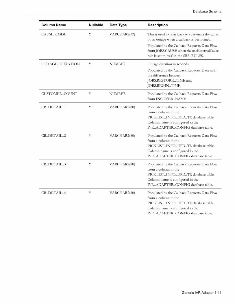
Database Schema
CAUSE_CODE Y VARCHAR2(32) This is used to relay back to customers the cause of an outage when a callback is performed.
Populated by the Callback Requests Data Flow from JOBS.CAUSE when the useExternalCause rule is set to ‘yes’ in the SRS_RULES.
OUTAGE_DURATION Y NUMBER Outage duration in seconds.
Populated by the Callback Requests Data with the difference between JOBS.RESTORE_TIME and JOBS.BEGIN_TIME.
CUSTOMER_COUNT Y NUMBER Populated by the Callback Requests Data Flow from INC.USER_NAME.
CB_DETAIL_1 Y VARCHAR2(80) Populated by the Callback Requests Data Flow from a column in the PICKLIST_INFO_UPD_TR database table. Column name is configured in the IVR_ADAPTER_CONFIG database table.
CB_DETAIL_2 Y VARCHAR2(80) Populated by the Callback Requests Data Flow from a column in the PICKLIST_INFO_UPD_TR database table. Column name is configured in the IVR_ADAPTER_CONFIG database table.
CB_DETAIL_3 Y VARCHAR2(80) Populated by the Callback Requests Data Flow from a column in the PICKLIST_INFO_UPD_TR database table. Column name is configured in the IVR_ADAPTER_CONFIG database table.
CB_DETAIL_4 Y VARCHAR2(80) Populated by the Callback Requests Data Flow from a column in the PICKLIST_INFO_UPD_TR database table. Column name is configured in the IVR_ADAPTER_CONFIG database table.
Column Name Nullable Data Type Description
Generic IVR Adapter 1-41

Database Schema
Stored Procedure Parameters
pk_ccb.submit_call
Data structures and parameters of the PK_CCB.SUBMIT_CALL stored procedure:
SUBTYPE udf_field IS VARCHAR2(256);TYPE input_call_rec IS RECORD ( call_source_id VARCHAR2(3), service_point_id trouble_calls.cust_id%TYPE, external_id trouble_calls.external_id%TYPE, account_number trouble_calls.cust_key%TYPE, trouble_code trouble_calls.cust_trouble_code%TYPE, first_name trouble_calls.cust_first_name%TYPE, last_name trouble_calls.cust_last_name%TYPE, phone trouble_calls.cust_phone%TYPE, phone_area trouble_calls.cust_phone_area%TYPE, alt_phone trouble_calls.alternate_phone%TYPE, priority trouble_calls.cust_priority%TYPE, critical_flag trouble_calls.cust_critical%TYPE, life_support_flag trouble_calls.cust_life_support%TYPE, call_id trouble_calls.general_area%TYPE, call_time trouble_calls.call_time%TYPE, call_comment trouble_calls.call_comment%TYPE, call_taker trouble_calls.usename%TYPE, call_type trouble_calls.call_type%TYPE, addr_building trouble_calls.addr_building%TYPE, addr_street trouble_calls.addr_street%TYPE, addr_cross_street trouble_calls.addr_street%TYPE, addr_city_state trouble_calls.addr_city%TYPE, drive_instr trouble_calls.drv_inst%TYPE, meet_time trouble_calls.meet_time%TYPE, meet_type trouble_calls.meet_type%TYPE, group_by_name trouble_calls.group_by_name%TYPE, device_id trouble_calls.cust_device_alias%TYPE, meter_id trouble_calls.meter_id%TYPE, trouble_queue trouble_calls.cust_trouble_queue%TYPE, trouble_location trouble_calls.trouble_loc%TYPE, x_coord trouble_calls.x_ref%TYPE, y_coord trouble_calls.y_ref%TYPE, appt_type trouble_calls.appt_type%TYPE, appt_time trouble_calls.appt_time%TYPE, appt_range trouble_calls.appt_range%TYPE, callback_flag trouble_calls.callback_request%TYPE, callback_before_time trouble_calls.callback_time%TYPE, callback_late_flag trouble_calls.callback_late%TYPE, intersection_cls trouble_calls.cust_device_cls%TYPE, intersection_idx trouble_calls.cust_device_idx%TYPE, cancel_flag trouble_calls.cust_call_cancel%TYPE, update_flag trouble_calls.update_existing_inc%TYPE, udf1 udf_field, udf2 udf_field, udf3 udf_field, udf4 udf_field, udf5 udf_field);
-- new/updated trouble call PROCEDURE submit_call ( p_call IN input_call_rec, p_err_no OUT NUMBER,
1-42 Oracle Utilities Network Management System Adapters Guide
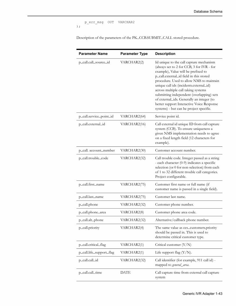
Database Schema
p_err_msg OUT VARCHAR2);
Description of the parameters of the PK_CCB.SUBMIT_CALL stored procedure.
Parameter Name Parameter Type Description
p_call.call_source_id VARCHAR2(2) Id unique to the call capture mechanism (always set to 2 for CCB, 3 for IVR - for example), Value will be prefixed to p_call.external_id field in this stored procedure. Used to allow NMS to maintain unique call ids (incidents.external_id) across multiple call taking systems submitting independent (overlapping) sets of external_ids. Generally an integer (to better support Interactive Voice Response systems) - but can be project specific.
p_call.service_point_id VARCHAR2(64) Service point id.
p_call.external_id VARCHAR2(16) Call external id unique ID from call capture system (CCB). To ensure uniqueness a given NMS implementation needs to agree on a fixed length field (12 characters for example).
p_call. account_number VARCHAR2(30) Customer account number.
p_call.trouble_code VARCHAR2(32) Call trouble code. Integer passed as a string - each character (0-9) indicates a specific selection (or 0 for non-selection) from each of 1 to 32 different trouble call categories. Project configurable.
p_call.first_name VARCHAR2(75) Customer first name or full name (if customer name is passed in a single field).
p_call.last_name VARCHAR2(75) Customer last name.
p_call.phone VARCHAR2(32) Customer phone number.
p_call.phone_area VARCHAR2(8) Customer phone area code.
p_call.alt_phone VARCHAR2(32) Alternative/callback phone number.
p_call.priority VARCHAR2(4) The same value as ces_customers.priority should be passed in. This is used to determine critical customer type.
p_call.critical_flag VARCHAR2(1) Critical customer (Y/N)
p_call.life_support_flag VARCHAR2(1) Life support flag (Y/N).
p_call.call_id VARCHAR2(32) Call identifier (for example, 911 call id) - mapped to general_area.
p_call.call_time DATE Call capture time from external call capture system
Generic IVR Adapter 1-43

Database Schema
p_call.call_comment VARCHAR2(255) Comments
p_call.call_taker VARCHAR2(32) Call taker id.
p_call.call_type VARCHAR2(8) Call type.
CC&B should leave this field empty.
p_call.addr_building VARCHAR2(10) Building/block number.
p_call.addr_street VARCHAR2(255) Street address or name of the first intersection street.
p_call.addr_cross_street VARCHAR2(255) Name of the second intersection (cross) street.
p_call.addr_city_state VARCHAR2(45) City and (optionally) state.
p_call.drive_instr VARCHAR2(180) Driving instructions.
p_call.meet_time DATE Meet time.
p_call.meet_type NUMBER Meet action code.Possible values:• 0 - for non-meet calls
• 1 - create new meet
• 2 - reschedule existing meet
• 3- cancel existing meet
p_call.group_by_name VARCHAR2(127) Optional control zone name for fuzzy calls.
p_call.device_id VARCHAR2(32) Device alias.
p_call.meter_id VARCHAR2(32) Meter number.
p_call.trouble_queue VARCHAR2(10) Trouble queue (Tree Trimming, Underground, etc)
p_call.trouble_location VARCHAR2(255) Trouble location.
p_call.x_coord NUMBER X coordinate in the NMS electrical network model coordinate system (generally NOT lat/long). If not provided JMService will default to the coordinates for the supply_node from the point_coordinates table.
p_call.y_coord NUMBER Y coordinate - match for X coordinate above.
p_call.appt_type NUMBER Appointment type.
p_call.appt_time DATE Appointment time.
p_call.appt_range NUMBER Appointment time window in minutes.
Parameter Name Parameter Type Description
1-44 Oracle Utilities Network Management System Adapters Guide
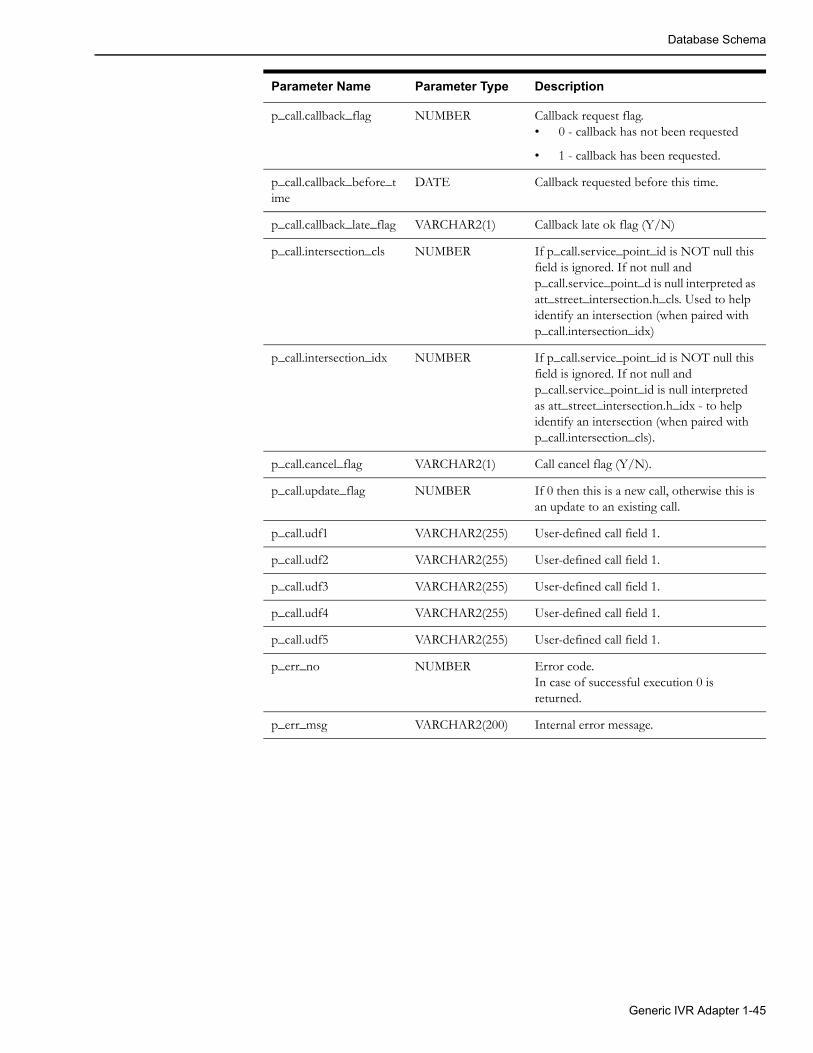
Database Schema
p_call.callback_flag NUMBER Callback request flag.• 0 - callback has not been requested
• 1 - callback has been requested.
p_call.callback_before_time
DATE Callback requested before this time.
p_call.callback_late_flag VARCHAR2(1) Callback late ok flag (Y/N)
p_call.intersection_cls NUMBER If p_call.service_point_id is NOT null this field is ignored. If not null and p_call.service_point_d is null interpreted as att_street_intersection.h_cls. Used to help identify an intersection (when paired with p_call.intersection_idx)
p_call.intersection_idx NUMBER If p_call.service_point_id is NOT null this field is ignored. If not null and p_call.service_point_id is null interpreted as att_street_intersection.h_idx - to help identify an intersection (when paired with p_call.intersection_cls).
p_call.cancel_flag VARCHAR2(1) Call cancel flag (Y/N).
p_call.update_flag NUMBER If 0 then this is a new call, otherwise this is an update to an existing call.
p_call.udf1 VARCHAR2(255) User-defined call field 1.
p_call.udf2 VARCHAR2(255) User-defined call field 1.
p_call.udf3 VARCHAR2(255) User-defined call field 1.
p_call.udf4 VARCHAR2(255) User-defined call field 1.
p_call.udf5 VARCHAR2(255) User-defined call field 1.
p_err_no NUMBER Error code.In case of successful execution 0 is returned.
p_err_msg VARCHAR2(200) Internal error message.
Parameter Name Parameter Type Description
Generic IVR Adapter 1-45

Database Schema
pk_ccb.job_history
Stored procedure PK_CCB.JOB_HISTORY allows caller to retrieve list of jobs matching passed in search condition.
The following types of search conditions are supported:
• Search for specific customer by service point id, premise id or account number.
• Location-based search. Search for jobs at or nearby specified location. Location can be street intersection or street segment (block).
• Fuzzy outage search. Search for fuzzy jobs by external id, call identifier, caller name or caller phone.
• Custom search. To use custom search the stored procedure has to be modified by the project. Additional search parameters are passed in the 'p_custom' field.
CREATE OR REPLACE TYPE customer_search_obj AS OBJECT ( serv_point_id VARCHAR2(64), premise_id NUMBER, account_number VARCHAR2(30))
CREATE OR REPLACE TYPE location_search_obj AS OBJECT ( city VARCHAR2(200), state VARCHAR2(30), street1 VARCHAR2(200), street2 VARCHAR2(200), block_number NUMBER)
CREATE OR REPLACE TYPE fuzzy_search_obj AS OBJECT ( external_id VARCHAR2(200), call_id VARCHAR2(200), caller_name VARCHAR2(200), caller_phone VARCHAR2(200))
CREATE OR REPLACE TYPE custom_search_obj AS OBJECT ( field1 VARCHAR2(200), field2 VARCHAR2(200), field3 VARCHAR2(200), field4 VARCHAR2(200), field5 VARCHAR2(200))
TYPE nms_cursor IS REF CURSOR;
-- Get job history.PROCEDURE job_history ( p_cust IN customer_search_obj, p_loc IN location_search_obj, p_fuzzy IN fuzzy_search_obj, p_custom IN custom_search_obj, p_num_days IN NUMBER, p_jobs OUT nms_cursor, p_err_no OUT NUMBER, p_err_msg OUT VARCHAR2);
1-46 Oracle Utilities Network Management System Adapters Guide

Database Schema
Description of the parameters of the PK_CCB.JOB_HISTORY stored procedure.
Parameter Name Parameter Type Description
p_cust.serv_point_id
VARCHAR2(64) Service point id.
p_cust.premise_id NUMBER Service location (premise id).
p_cust.account_number
VARCHAR2(30) Customer account number.
p_loc.city VARCHAR2(200) City.
p_loc.state VARCHAR2(30) State.
p_loc.street1 VARCHAR2(200) Street name. This field is used in both street intersection search and street segment search.
p_loc.street2 VARCHAR2(200) Second street name for street intersection search.
p_loc.block_number
NUMBER Block number for street segment search.
p_fuzzy.external_id VARCHAR2(200) Call external id.
p_fuzzy.call_id VARCHAR2(200) Call identifier (for example, id for 911 calls).
p_fuzzy.caller_name
VARCHAR2(200) Caller name.
p_fuzzy.caller_phone
VARCHAR2(200) Caller phone number.
p_custom.xxx Implementation-defined search parameters.
p_cmp_days NUMBER If greater than 0 then switching plans completed within specified number of days in the past will be returned in addition to current and future switching plans.
p_jobs nms_cursor Returned jobs information.
p_err_no NUMBER Error code.In case of successful execution 0 is returned.
p_err_msg VERCHAR2(200) Internal error message.
For each returned job the following information is included.
TYPE job_rec IS RECORD ( serv_point_id ces_customers.id%TYPE, serv_point_addr ces_customers.address%TYPE, event_idx jobs.event_idx%TYPE, begin_time jobs.begin_time%TYPE, est_rest_time jobs.est_rest_time%TYPE, est_rest_time_source jobs.est_source%TYPE, restore_time jobs.restore_time%TYPE,
Generic IVR Adapter 1-47

Database Schema
cust_out jobs.num_cust_out%TYPE, comments jobs.operator_comment%TYPE, alarm_state jobs.alarm_state%TYPE, alarm_state_desc te_valid_states.description%TYPE, trouble_location jobs.display_name%TYPE, status jobs.status%TYPE, device_class jobs.devcls_name%TYPE, trouble_code jobs.trouble_code%TYPE, feeder_name jobs.feeder_name%TYPE, cause jobs.cause%TYPE, description jobs.description%TYPE, referral_group jobs.referral_group%TYPE, last_update_time jobs.last_update_time%TYPE, udf1 udf_field, udf2 udf_field, udf3 udf_field, udf4 udf_field, udf5 udf_field);
Field Name Field Type Description
serv_point_id VARCHAR2(64) Service point id.
serv_point_addr VARCHAR2(200) Service point address
event_idx NUMBER Event index.
begin_time DATE Outage begin time.
est_rest_time DATE Estimated restoration time (ERT).
est_rest_time_source
VARCHAR2(1) ERT source. Possible values:• N - no ERT
• I - Initial ERT
• C - manually entered ERT (from crew or NMS operator)
• S - ERT calculated by Storm Management
• O - ERT calculated by Storm Management (crew on-site)
• P - Non-publisher ERT
• G - ERT override is in effect
• D - ERT delay is in effect
restore_time DATE Outage restoration time.
cust_out NUMBER Number of customers affected by the outage.
comments VARCHAR2(255) Operator's comment. Note some customers increase this to max allowed (4k).
alarm_state VARCHAR2(32) Outage state.
1-48 Oracle Utilities Network Management System Adapters Guide

Database Schema
alarm_state_desc VARCHAR2(80) Description of the outage state.
trouble_location VARCHAR2(255)
status NUMBER Job type.Possible values:• 0 - Fuzzy outage.
• 1 - Probable/predicted service outage.
• 2 - Probable/predicted device outage.
• 3 - Real service outage.
• 4 - Real device outage.
• 7 - Non-outage.
• 8 - Critical meet.
• 9 - Future meet.
• 10 - Confirmed service outage.
• 11 - Confirmed secondary outage.
• 13 - Probable/predicted momentary outage.
• 14 - Real momentary outage.
• 15 - Planned outage.
• 16 - Non-electric event.
• 17 - Master switching job.
• 18 - Fault current event.
device_class VARCHAR2(32) Outage device class name (e.g., fuse)
trouble_code VARCHAR2(128) Trouble code.
feeder_name VARCHAR2(32) Feeder name.
cause VARCHAR2(32) Outage cause.
description VARCHAR2(128) Job description.
referral_group VARCHAR2(32) Referral group.
last_update_time DATE Timestamp of the latest update to the outage record.
udf1 VARCHAR2(255) Job user-defined field 1.
udf2 VARCHAR2(255) Job user-defined field 2.
udf3 VARCHAR2(255) Job user-defined field 3.
udf4 VARCHAR2(255) Job user-defined field 4.
udf5 VARCHAR2(255) Job user-defined field 5.
Field Name Field Type Description
Generic IVR Adapter 1-49
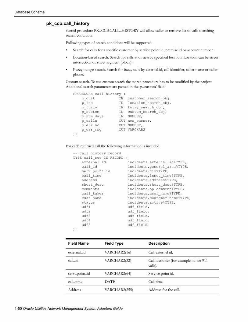
Database Schema
pk_ccb.call_history
Stored procedure PK_CCB.CALL_HISTORY will allow caller to retrieve list of calls matching search condition.
Following types of search conditions will be supported:
• Search for calls for a specific customer by service point id, premise id or account number.
• Location-based search. Search for calls at or nearby specified location. Location can be street intersection or street segment (block).
• Fuzzy outage search. Search for fuzzy calls by external id, call identifier, caller name or caller phone.
Custom search. To use custom search the stored procedure has to be modified by the project. Additional search parameters are passed in the 'p_custom' field.
PROCEDURE call_history ( p_cust IN customer_search_obj, p_loc IN location_search_obj, p_fuzzy IN fuzzy_search_obj, p_custom IN custom_search_obj, p_num_days IN NUMBER, p_calls OUT nms_cursor, p_err_no OUT NUMBER, p_err_msg OUT VARCHAR2);
For each returned call the following information is included.
-- call history recordTYPE call_rec IS RECORD ( external_id incidents.external_id%TYPE, call_id incidents.general_area%TYPE, serv_point_id incidents.cid%TYPE, call_time incidents.input_time%TYPE, address incidents.address%TYPE, short_desc incidents.short_desc%TYPE, comments incidents.op_comment%TYPE, call_taker incidents.user_name%TYPE, cust_name incidents.customer_name%TYPE, status incidents.active%TYPE, udf1 udf_field, udf2 udf_field, udf3 udf_field, udf4 udf_field, udf5 udf_field);
Field Name Field Type Description
external_id VARCHAR2(16) Call external id.
call_id VARCHAR2(32) Call identifier (for example, id for 911 calls).
serv_point_id VARCHAR2(64) Service point id.
call_time DATE Call time.
Address VARCHAR2(255) Address for the call.
1-50 Oracle Utilities Network Management System Adapters Guide

Database Schema
pk_ccb.switching_history
The stored procedure PK_CCB.SWITCHING_HISTORY allows a caller to retrieve a list of current, future, and (optionally) past switching plans affecting a given customer.
.
PROCEDURE switching_history ( p_cust IN customer_search_obj, p_custom IN custom_search_obj, p_num_days IN NUMBER, p_sw_plans OUT nms_cursor, p_err_no OUT NUMBER, p_err_msg OUT VARCHAR2);
Description of the parameters of the PK_CCB.SWITCHING_HISTORY stored procedure.
short_desc VARCHAR2(256) Trouble code.
Comments VARCHAR2(255) Comments.
call_taker VARCHAR2(32) Call taker id.
cust_name VARCHAR2(75) Customer/caller name.
Status VARCHAR2(1) Call status. Possible values (other values can exist in NMS but they would not be returned by this procedure):"Y - active call "N - inactive/restored call "C - canceled call "E - call belongs to canceled job
udf1 VARCHAR2(255) Call user-defined field 1.
udf2 VARCHAR2(255) Call user-defined field 2.
udf3 VARCHAR2(255) Call user-defined field 3.
udf4 VARCHAR2(255) Call user-defined field 4.
udf5 VARCHAR2(255) Call user-defined field 5.
Field Name Field Type Description
Parameter Name Parameter Type Description
p_cust.serv_point_id VARCHAR2(64) Service point id.
p_cust.premise_id NUMBER Service location (premise id).
p_cust.account_number VARCHAR2(30) Customer account number.
p_custom Implementation-defined search parameters.
p_sw_plans nms_cursor Returned switching plan information.
p_err_no NUMBER Error codeIn case of successful execution 0 is returned.
Generic IVR Adapter 1-51

Database Schema
For each returned switching plan following information is included.
Field Name Field Type Description
plan_class VARCHAR2(32) Switching plan type (planned, emergency, ….).
plan_number NUMBER Switching plan number.
start_date DATE Switching plan start date.
end_date DATE Switching plan end date.
State VARCHAR2(32) Switching plan state.
work_district VARCHAR2(500)
work_location VARCHAR2(500)
work_description VARCHAR2(500)
serv_point_id VARCHAR2(64) Service point id.
serv_point_addr VARCHAR2(200) Service point address
-- switching plan recordTYPE switching_plan_rec IS RECORD ( plan_class swman_sheet_cls.switch_sheet_type%TYPE, plan_number swman_sheet.switch_sheet_idx%TYPE, start_date swman_sheet.start_date%TYPE, end_date swman_sheet.finish_date%TYPE, device_alias swman_sheet.device_alias%TYPE, state te_valid_states.state_name%TYPE, work_district swman_sheet_extn.string_value%TYPE, work_location swman_sheet_extn.string_value%TYPE, work_description swman_sheet_extn.string_value%TYPE, serv_point_id ces_customers.id%TYPE, serv_point_addr ces_customers.address%TYPE, udf1 udf_field, udf2 udf_field, udf3 udf_field, udf4 udf_field, udf5 udf_field, udf6 udf_field, udf7 udf_field, udf8 udf_field, udf9 udf_field, udf10 udf_field);
p_err_msg VARCHAR2(200) Error message.
Parameter Name Parameter Type Description
1-52 Oracle Utilities Network Management System Adapters Guide

Database Schema
pk_ccb.trouble_code_config
Stored procedure PK_CCB.TROUBLE_CODE_CONFIG allows caller to retrieve list of trouble codes configured in the Oracle Utilities Network Management System.
Field Name Field Type Description
p_trouble_codes nms_cursor Returned trouble code information.
p_err_no NUMBER Error codeIn case of successful execution 0 is returned.
p_err_msg VARCHAR2(200) Error message
PROCEDURE trouble_code_config ( p_trouble_codes OUT nms_cursor, p_err_no OUT NUMBER, p_err_msg OUT VARCHAR2);
For each returned trouble code following information is included:
Field Name Field Type Description
group_name VARCHAR2(20) Trouble code group name
group_order NUMBER Trouble code group order
code_name VARCHAR2(40) Trouble code name
code_num NUMBER Trouble code number within its group
short_desc VARCHAR2(25) Short description of the trouble code
description VARCHAR2(70) Long description of the trouble code
-- trouble code configuration recordTYPE trouble_code_rec IS RECORD ( group_name srs_trouble_codes.group_name%TYPE, group_order srs_trouble_codes.group_order%TYPE, code_name srs_trouble_codes.code_name%TYPE, code_num srs_trouble_codes.code_num%TYPE, short_desc srs_trouble_codes.short_desc%TYPE, description srs_trouble_codes.description%TYPE);
Generic IVR Adapter 1-53

Database Schema
pr_trouble_calls
The Generic IVR Adapter provides the pr_trouble_calls procedure to be used by the external application to insert trouble calls in the TROUBLE_CALLS table. Refer to Trouble Calls on page 1-3 for Data Flow details.
Below is a high level description of what is done inside the stored procedure
• Upon invoking the stored procedure, the p_premise_id parameter is used to query the CES_CUSTOMERS table (via the SERV_LOC_ID field) to retrieve the ACCOUNT_NUMBER, H_CLS and H_IDX fields of the said table. The value of these fields is placed in the corresponding columns of the TROUBLE_CALLS table.
• Other parameter values are inserted to corresponding fields on the TROUBLE_CALL table.
• Several TROUBLE_CALLS columns will have default value when no parameter value is supplied.
• Should there be an error in the record insert, an Oracle error is returned.
Note: If the given premise id has multiple accounts associated with it, only one account (i.e., the first account) is used.
Below are details about each parameter of the pr_trouble_calls stored procedure. Note that the field name column indicates the corresponding column that is populated in the TROUBLE_CALLS table.
Parameters
Parameter Direction Data Type Field Name Comment
p_premise_id In VARCHAR2 PREMISE_ID The value is inserted as is.
p_trouble_code In VARCHAR2 TROUBLE_CODE Defaults to ‘1’ followed by a certain number of ‘0’. If no value was supplied. The total length of the string is the total number of distinct groups in the SRS_TROUBLE_CODES table.
p_callback_ind In VARCHAR2 CALLBACK_INDICATOR The possible values are as follows:
‘0’ - callback not requested
‘1’ - callback requested
Defaults to ‘1’ if no value is supplied.
‘Y’ is translated to ‘1’.
‘N’ is translated to ‘0’.
p_call_time In DATE CALL_TIME Defaults to the database system date if no value is supplied
p_call_taker_id In VARCHAR2 CALL_TAKER_ID The value is inserted as is.
p_alternate_phone In VARCHAR2 ALTERNATE_PHONE The value is inserted as is.
p_customer_comment In VARCHAR2 CUSTOMER_COMMENT The value is inserted as is.
1-54 Oracle Utilities Network Management System Adapters Guide

Database Schema
p_customer_phone In VARCHAR2 CUSTOMER_PHONE The value is inserted as is.
p_customer_name In VARCHAR2 CUSTOMER_NAME The value is inserted as is.
p_customer_address In VARCHAR2 CUSTOMER_ADDRESS The value is inserted as is.
p_customer_city_state In VARCHAR2 CUSTOMER_CITY_STATE The value is inserted as is.
p_customer_priority In VARCHAR2 CUSTOMER_PRIORITY The value is inserted as is.
p_external_id In VARCHAR2 EXTERNAL_ID The value is inserted as is.
p_device_alias In VARCHAR2 DEVICE_ALIAS The value is inserted as is.
p_check_cutoff_ind In VARCHAR2 CHECK_CUTOFF_IND The possible values are as follows:
‘Y’ - check if the customer is disconnected
‘N’ - do not perform checking.
Defaults to ‘N’ if no value is supplied
p_callback_late_ind In VARCHAR2 CALLBACK_LATE_IND The possible values are as follows:
‘Y’ - It is OK to call back even when it is already late.
‘N’ - It is not OK to call back when it is already late.
Defaults to ‘N’ if no value is supplied
p_callback_before_time In DATE CALLBACK_BEFORE_TIME The value is inserted as is.
p_trouble_queue In VARCHAR2 TROUBLE_QUEUE The value is inserted as is.
p_meter_id In VARCHAR2 METER_ID The value is inserted as is.
p_supply_id In NUMBER SUPPLY_ID The value is inserted as is.
p_cust_phone_area In VARCHAR2 CUST_PHONE_AREA The value is inserted as is.
p_cust_last_name In VARCHAR2 CUST_LAST_NAME The value is inserted as is.
p_general_area In VARCHAR2 GENERAL_AREA The value is inserted as is.
p_cust_order_num In VARCHAR2 CUST_ORDER_NUM The value is inserted as is.
p_drv_inst In VARCHAR2 DRV_INST The value is inserted as is.
p_cust_life_support In VARCHAR2 CUST_LIFE_SUPPORT The value is inserted as is.
p_cust_call_cancel In VARCHAR2 CUST_CALL_CANCEL The value is inserted as is.
p_short_desc In VARCHAR2 SHORT_DESC The value is inserted as is.
p_addr_building In VARCHAR2 ADDR_BUILDING The value is inserted as is.
Parameter Direction Data Type Field Name Comment
Generic IVR Adapter 1-55
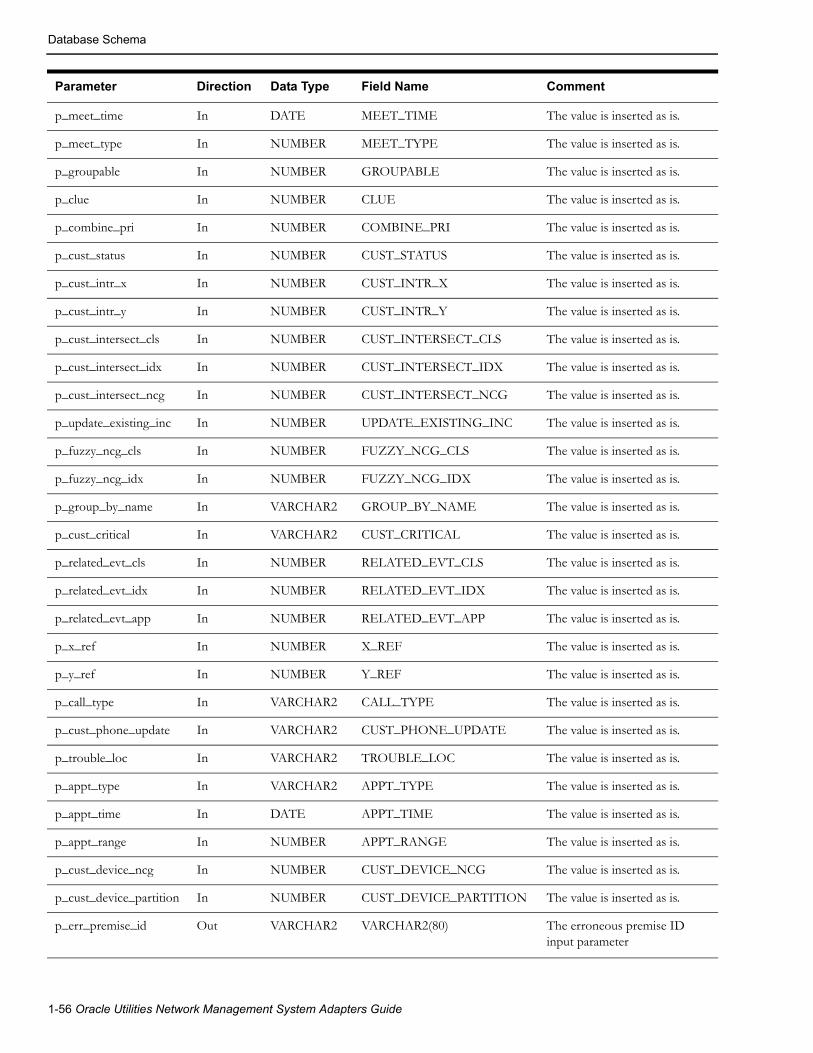
Database Schema
p_meet_time In DATE MEET_TIME The value is inserted as is.
p_meet_type In NUMBER MEET_TYPE The value is inserted as is.
p_groupable In NUMBER GROUPABLE The value is inserted as is.
p_clue In NUMBER CLUE The value is inserted as is.
p_combine_pri In NUMBER COMBINE_PRI The value is inserted as is.
p_cust_status In NUMBER CUST_STATUS The value is inserted as is.
p_cust_intr_x In NUMBER CUST_INTR_X The value is inserted as is.
p_cust_intr_y In NUMBER CUST_INTR_Y The value is inserted as is.
p_cust_intersect_cls In NUMBER CUST_INTERSECT_CLS The value is inserted as is.
p_cust_intersect_idx In NUMBER CUST_INTERSECT_IDX The value is inserted as is.
p_cust_intersect_ncg In NUMBER CUST_INTERSECT_NCG The value is inserted as is.
p_update_existing_inc In NUMBER UPDATE_EXISTING_INC The value is inserted as is.
p_fuzzy_ncg_cls In NUMBER FUZZY_NCG_CLS The value is inserted as is.
p_fuzzy_ncg_idx In NUMBER FUZZY_NCG_IDX The value is inserted as is.
p_group_by_name In VARCHAR2 GROUP_BY_NAME The value is inserted as is.
p_cust_critical In VARCHAR2 CUST_CRITICAL The value is inserted as is.
p_related_evt_cls In NUMBER RELATED_EVT_CLS The value is inserted as is.
p_related_evt_idx In NUMBER RELATED_EVT_IDX The value is inserted as is.
p_related_evt_app In NUMBER RELATED_EVT_APP The value is inserted as is.
p_x_ref In NUMBER X_REF The value is inserted as is.
p_y_ref In NUMBER Y_REF The value is inserted as is.
p_call_type In VARCHAR2 CALL_TYPE The value is inserted as is.
p_cust_phone_update In VARCHAR2 CUST_PHONE_UPDATE The value is inserted as is.
p_trouble_loc In VARCHAR2 TROUBLE_LOC The value is inserted as is.
p_appt_type In VARCHAR2 APPT_TYPE The value is inserted as is.
p_appt_time In DATE APPT_TIME The value is inserted as is.
p_appt_range In NUMBER APPT_RANGE The value is inserted as is.
p_cust_device_ncg In NUMBER CUST_DEVICE_NCG The value is inserted as is.
p_cust_device_partition In NUMBER CUST_DEVICE_PARTITION The value is inserted as is.
p_err_premise_id Out VARCHAR2 VARCHAR2(80) The erroneous premise ID input parameter
Parameter Direction Data Type Field Name Comment
1-56 Oracle Utilities Network Management System Adapters Guide
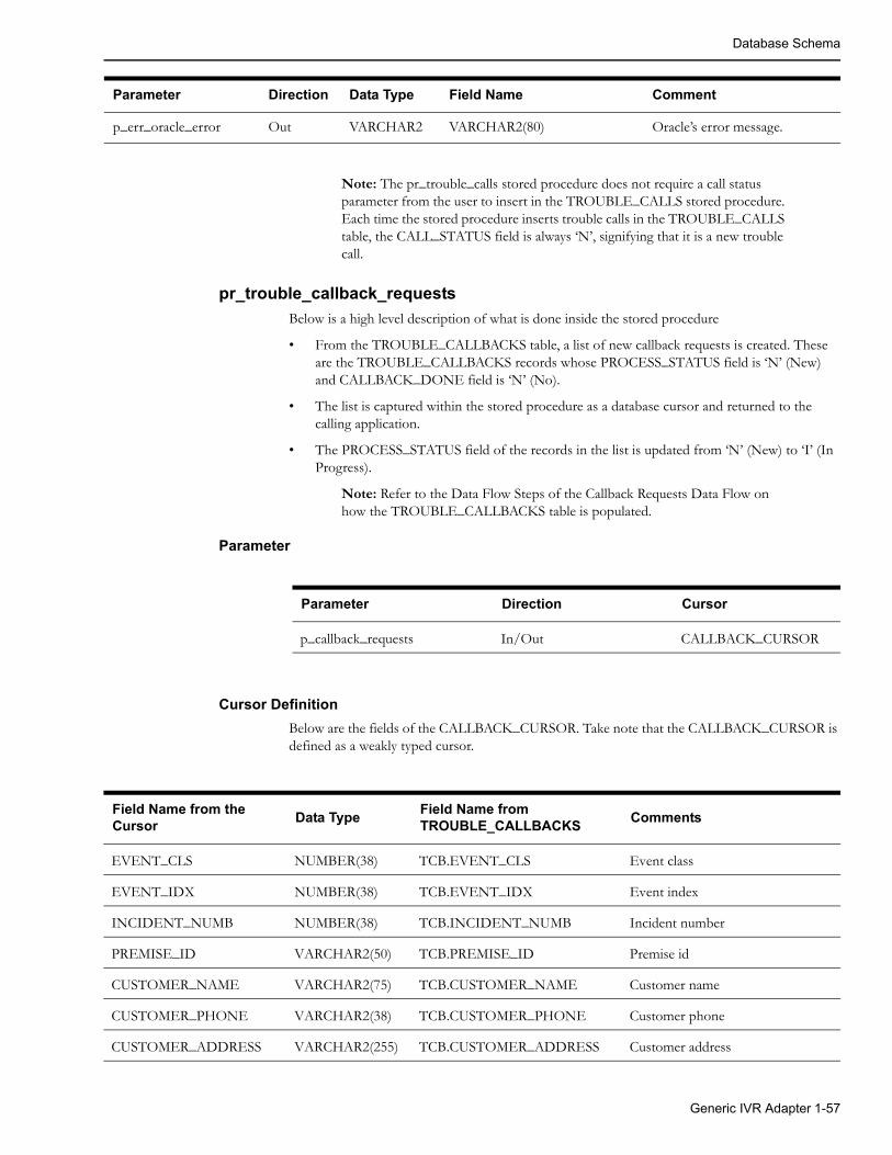
Database Schema
Note: The pr_trouble_calls stored procedure does not require a call status parameter from the user to insert in the TROUBLE_CALLS stored procedure. Each time the stored procedure inserts trouble calls in the TROUBLE_CALLS table, the CALL_STATUS field is always ‘N’, signifying that it is a new trouble call.
pr_trouble_callback_requests
Below is a high level description of what is done inside the stored procedure
• From the TROUBLE_CALLBACKS table, a list of new callback requests is created. These are the TROUBLE_CALLBACKS records whose PROCESS_STATUS field is ‘N’ (New) and CALLBACK_DONE field is ‘N’ (No).
• The list is captured within the stored procedure as a database cursor and returned to the calling application.
• The PROCESS_STATUS field of the records in the list is updated from ‘N’ (New) to ‘I’ (In Progress).
Note: Refer to the Data Flow Steps of the Callback Requests Data Flow on how the TROUBLE_CALLBACKS table is populated.
Parameter
Parameter Direction Cursor
p_callback_requests In/Out CALLBACK_CURSOR
Cursor Definition
Below are the fields of the CALLBACK_CURSOR. Take note that the CALLBACK_CURSOR is defined as a weakly typed cursor.
p_err_oracle_error Out VARCHAR2 VARCHAR2(80) Oracle’s error message.
Parameter Direction Data Type Field Name Comment
Field Name from the Cursor
Data TypeField Name from TROUBLE_CALLBACKS
Comments
EVENT_CLS NUMBER(38) TCB.EVENT_CLS Event class
EVENT_IDX NUMBER(38) TCB.EVENT_IDX Event index
INCIDENT_NUMB NUMBER(38) TCB.INCIDENT_NUMB Incident number
PREMISE_ID VARCHAR2(50) TCB.PREMISE_ID Premise id
CUSTOMER_NAME VARCHAR2(75) TCB.CUSTOMER_NAME Customer name
CUSTOMER_PHONE VARCHAR2(38) TCB.CUSTOMER_PHONE Customer phone
CUSTOMER_ADDRESS VARCHAR2(255) TCB.CUSTOMER_ADDRESS Customer address
Generic IVR Adapter 1-57
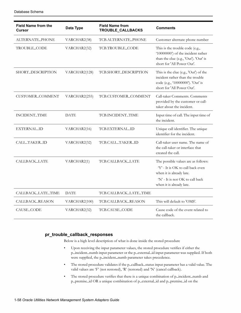
Database Schema
pr_trouble_callback_responsesBelow is a high level description of what is done inside the stored procedure
• Upon receiving the input parameter values, the stored procedure verifies if either the p_incident_numb input parameter or the p_external_id input parameter was supplied. If both were supplied, the p_incident_numb parameter takes precedence.
• The stored procedure validates if the p_callback_status input parameter has a valid value. The valid values are ‘F’ (not restored), ‘R’ (restored) and ‘N’ (cancel callback).
• The stored procedure verifies that there is a unique combination of p_incident_numb and p_premise_id OR a unique combination of p_external_id and p_premise_id on the
ALTERNATE_PHONE VARCHAR2(38) TCB.ALTERNATE_PHONE Customer alternate phone number
TROUBLE_CODE VARCHAR2(32) TCB.TROUBLE_CODE This is the trouble code (e.g., ‘10000000’) of the incident rather than the clue (e.g., 'Out'). 'Out' is short for 'All Power Out'.
SHORT_DESCRIPTION VARCHAR2(128) TCB.SHORT_DESCRIPTION This is the clue (e.g., 'Out') of the incident rather than the trouble code (e.g., ‘10000000’). 'Out' is short for 'All Power Out'.
CUSTOMER_COMMENT VARCHAR2(255) TCB.CUSTOMER_COMMENT Call-taker Comments. Comments provided by the customer or call-taker about the incident.
INCIDENT_TIME DATE TCB.INCIDENT_TIME Input time of call. The input time of the incident.
EXTERNAL_ID VARCHAR2(16) TCB.EXTERNAL_ID Unique call identifier. The unique identifier for the incident.
CALL_TAKER_ID VARCHAR2(32) TCB.CALL_TAKER_ID Call-taker user name. The name of the call-taker or interface that created the call.
CALLBACK_LATE VARCHAR2(1) TCB.CALLBACK_LATE The possible values are as follows:
‘Y’ - It is OK to call back even when it is already late.
‘N’ - It is not OK to call back when it is already late.
CALLBACK_LATE_TIME DATE TCB.CALLBACK_LATE_TIME
CALLBACK_REASON VARCHAR2(100) TCB.CALLBACK_REASON This will default to 'OMS'.
CAUSE_CODE VARCHAR2(32) TCB.CAUSE_CODE Cause code of the event related to the callback.
Field Name from the Cursor
Data TypeField Name from TROUBLE_CALLBACKS
Comments
1-58 Oracle Utilities Network Management System Adapters Guide

Database Schema
TROUBLE_CALLBACKS table, whichever among p_incident_numb or p_external_id was supplied.
• The TROUBLE_CALLBACKS table is updated for the p_incident_numb and p_premise_id combination OR the p_external_id and p_premise_id combination. The following fields are updated:
• The callback's CALLBACK_DONE field to 'Y' signifying that the callback was already done.
• The callback's CALLBACK_TIME field with provided p_callback_time stored procedure parameter. CALLBACK_TIME field defaults to the system date if no value was provided.
• The callback's CALLBACK_STATUS field with the appropriate callback response code.
• Should any of these steps fail, the stored procedure exits and returns the appropriate error.
Note: Refer to the Data Flow Steps of the Callback Response Data Flow on how the TROUBLE_CALLBACKS table is populated.
Parameters
Parameter Direction Data Type Field Name Comments
p_incident_numb In NUMBER INCIDENT_NUMB Incident Number. Either this or the p_external_id parameter has to be supplied
p_external_id In VARCHAR2 EXTERNAL_ID External Id. Either this or the p_incident_numb parameter has to be supplied
p_premise_id In VARCHAR2 PREMISE_ID Premise Id.
p_callback_status In VARCHAR2 CALLBACK_STATUS The valid values are as follows:
'F' - Not Restored Callback
'R' - Restored Callback
'N' - Cancel Callback, unable to get a response
p_callback_time In DATE CALLBACK_TIME Defaulted to the system date if no value was supplied
p_err_incident_numb Out NUMBER The erroneous incident number input parameter
p_err_external_id Out VARCHAR2 The erroneous external ID input parameter
p_err_premise_id Out VARCHAR2 The erroneous premise ID input parameter
p_err_oracle_error Out VARCHAR2 Oracle’s error message
Generic IVR Adapter 1-59
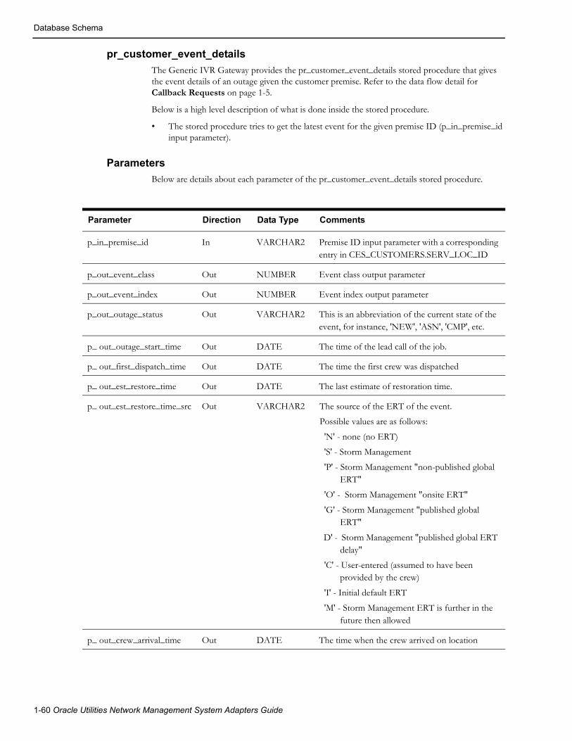
Database Schema
pr_customer_event_details
The Generic IVR Gateway provides the pr_customer_event_details stored procedure that gives the event details of an outage given the customer premise. Refer to the data flow detail for Callback Requests on page 1-5.
Below is a high level description of what is done inside the stored procedure.
• The stored procedure tries to get the latest event for the given premise ID (p_in_premise_id input parameter).
Parameters
Below are details about each parameter of the pr_customer_event_details stored procedure.
Parameter Direction Data Type Comments
p_in_premise_id In VARCHAR2 Premise ID input parameter with a corresponding entry in CES_CUSTOMERS.SERV_LOC_ID
p_out_event_class Out NUMBER Event class output parameter
p_out_event_index Out NUMBER Event index output parameter
p_out_outage_status Out VARCHAR2 This is an abbreviation of the current state of the event, for instance, 'NEW', 'ASN', 'CMP', etc.
p_ out_outage_start_time Out DATE The time of the lead call of the job.
p_ out_first_dispatch_time Out DATE The time the first crew was dispatched
p_ out_est_restore_time Out DATE The last estimate of restoration time.
p_ out_est_restore_time_src Out VARCHAR2 The source of the ERT of the event.
Possible values are as follows:
'N' - none (no ERT)
'S' - Storm Management
'P' - Storm Management "non-published global ERT"
'O' - Storm Management "onsite ERT"
'G' - Storm Management "published global ERT"
D' - Storm Management "published global ERT delay"
'C' - User-entered (assumed to have been provided by the crew)
'I' - Initial default ERT
'M' - Storm Management ERT is further in the future then allowed
p_ out_crew_arrival_time Out DATE The time when the crew arrived on location
1-60 Oracle Utilities Network Management System Adapters Guide

Database Schema
p_ out_completion_time Out DATE The time the event has been completed. This implies power restoration, the crew(s) are gone, and the event is completed in the Event Details window.
p_ out_restoration_time Out DATE The time that power has been restored.
p_ out_case_note Out VARCHAR2 Comment
p_ out_status Out NUMBER Condition status
p_ out_active Out VARCHAR2 Possible values are as follows:
'Y' - Outage Is Active
'N' - Outage Is Not Active
p_out_alias Out VARCHAR2 The device alias.
P_out_event_type Out VARCHAR2 Possible values are as follows:OUTNONMEETPLANSWP
P_out_feeder_name Out VARCHAR2 The name of the feeder.
P_out_cause Out VARCHAR2 The cause of the outage if the SRS Rule useExternalCause is on.
P_out_num_calls Out NUMBER The number of calls.
P_out_num_cust_out Out NUMBER The number of customers out.
P_err_premise_id Out VARCHAR2
P_err_oracle_error Out VARCHAR2
Parameter Direction Data Type Comments
Generic IVR Adapter 1-61
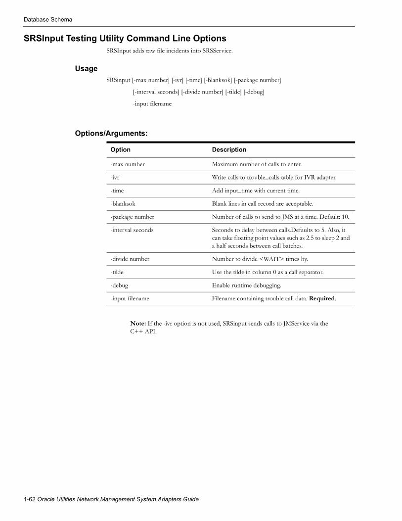
Database Schema
SRSInput Testing Utility Command Line OptionsSRSInput adds raw file incidents into SRSService.
Usage
SRSinput [-max number] [-ivr] [-time] [-blanksok] [-package number]
[-interval seconds] [-divide number] [-tilde] [-debug]
-input filename
Options/Arguments:
Option Description
-max number Maximum number of calls to enter.
-ivr Write calls to trouble_calls table for IVR adapter.
-time Add input_time with current time.
-blanksok Blank lines in call record are acceptable.
-package number Number of calls to send to JMS at a time. Default: 10.
-interval seconds Seconds to delay between calls.Defaults to 5. Also, it can take floating point values such as 2.5 to sleep 2 and a half seconds between call batches.
-divide number Number to divide <WAIT> times by.
-tilde Use the tilde in column 0 as a call separator.
-debug Enable runtime debugging.
-input filename Filename containing trouble call data. Required.
Note: If the -ivr option is not used, SRSinput sends calls to JMService via the C++ API.
1-62 Oracle Utilities Network Management System Adapters Guide
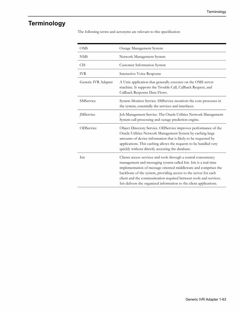
Terminology
TerminologyThe following terms and acronyms are relevant to this specification
OMS Outage Management System
NMS Network Management System
CIS Customer Information System
IVR Interactive Voice Response
Generic IVR Adapter A Unix application that generally executes on the OMS server machine. It supports the Trouble Call, Callback Request, and Callback Response Data Flows.
SMService System Monitor Service. SMService monitors the core processes in the system, essentially the services and interfaces.
JMService Job Management Service. The Oracle Utilities Network Management System call processing and outage prediction engine.
ODService Object Directory Service. ODService improves performance of the Oracle Utilities Network Management System by caching large amounts of device information that is likely to be requested by applications. This caching allows the requests to be handled very quickly without directly accessing the database.
Isis Clients access services and tools through a central concurrency management and messaging system called Isis. Isis is a real-time implementation of message oriented middleware and comprises the backbone of the system, providing access to the server for each client and the communication required between tools and services. Isis delivers the organized information to the client applications.
Generic IVR Adapter 1-63

Terminology
1-64 Oracle Utilities Network Management System Adapters Guide

Chapter 2SmallWorld GIS Adapter Template
The Oracle Smallworld data adapter template is a Smallworld Magik code template for an extraction tool to produce .mp files from the Smallworld GIS. This unsupported template is provided as an example for projects to use to facilitate the extraction from the Smallworld GIS to the Oracle Utilities Network Management System (NMS). It is located on the installed Oracle Utilities Network Management System in the $CES_HOME/sdk/gis directory as file SW_EXTRACTOR_TEMPLATE.zip.
SmallWorld GIS Adapter Template 2-1

2-2 Oracle Utilities Network Management System Adapters Guide
Chapter 3ESRI ArcGIS Adapter
Adapter OverviewOracle Network Management System has adapters for various ESRI ArcGIS systems. Please refer to http://support.oracle.com and search the Oracle Support Knowledge Base for “NMS ESRI Extractor” for information on supported versions of the adapter and download links.
Adapter DocumentationOracle Utilities Network Management System ArcGIS adapter documentation is included in the ArcGIS adapter release package.
ESRI ArcGIS Adapter 3-1

Adapter Documentation
3-2 Oracle Utilities Network Management System Adapters Guide

Chapter 4Intergraph G/Electric Adapter
Adapter OverviewOracle Utilities Network Management System has adapters for various Intergraph G/Electric systems. Please refer to http://support.oracle.com and search the Oracle Support Knowledge Base for “NMS Intergraph Extractor” for information on supported versions of the adapter and download links.
Adapter DocumentationOracle Utilities Network Management System Intergraph G/Electric adapter documentation is included in the Intergraph G/Electric adapter release package.
Intergraph G/Electric Adapter 4-1

Adapter Documentation
4-2 Oracle Utilities Network Management System Adapters Guide

Chapter 5Generic WebSphere MQ Adapter
This chapter includes the following topics:
• Introduction
• Hardware and Software Requirements
• Functional Description
• Adapter Installation
• High Availability
• Performance
• Data Flows
• Information Model
• Configure Queues for Required Data Flows
IntroductionThe purpose of this document is to provide an administration guide of the Oracle Utilities Network Management System Generic WebSphere MQ Adapter. This document will discuss the required process for installing and configuring the adapter to run with the appropriate Oracle Utilities Network Management System software.
The Oracle Utilities Network Management System Generic WebSphere MQ Adapter can serve as a data adapter between the Network Management System and a number of external systems, such as a Customer Information System (CIS) or an Interactive Voice Response (IVR) system. Additionally, this adapter could be used with external systems that need to input trouble calls into Network Management System but do not require other sophisticated data flows, such as High Volume Call Applications (HVCA), Automated Meter Reading (AMR), or Work Management Systems (WMS).
This interface depends upon IBM’s WebSphere MQ software as the intermediary repository for information passed between the Network Management System and the external system. This adapter is used only for the communication between IBM’s WebSphere MQ software and the Oracle Utilities Network Management System software suite. With the use of XML as the payload for data transmission, the adapter exchanges data between Oracle Utilities Network Management System and external systems as defined in the Oracle Utilities Network Management System WebSphere MQ XML schema documents. The required configuration of the adapter is described in the sections that follow.
Generic WebSphere MQ Adapter 5-1

Hardware and Software Requirements
TerminologyThe following terms and acronyms are relevant to this specification
OMS Outage Management System
Network Management System
Network Management System
SMService System Monitor Service. SMService monitors the core processes in the system, essentially the services and interfaces.
JMService Job Management Service. The Oracle Utilities Network Management System call processing and outage prediction engine.
MQSeries A queue-based messaging system developed by IBM. This system has been renamed to WebSphere MQ.
DTD Document type definition, used to define XML documents
XML Extensible Markup Language
XSL XML Style Sheet, used to reformat XML documents
XML Schema An XML standard for defining XML documents
CIS Customer Information System
IVR Interactive Voice Response system
SCADA Supervisory Control and Data Acquisition system
HA High availability, where Oracle Utilities Network Management System is configured with a pair of redundant servers. This is usually in the form of a hardware cluster and a shared drive that contains the database.
Hardware and Software Requirements
Oracle Utilities Network Management System EnvironmentThe Oracle Utilities Network Management System environment consists of a number of servers that are interconnected using the InterSys messaging system.
Adapter Server
The Generic WebSphere MQ Adapter environment may be resident on the same servers as the Oracle Utilities Network Management System services, or it may be implemented on a separate server. Specifications for a stand-alone adapter server:
• All Oracle Utilities Network Management System Unix and Linux operating systems are supported.
• IBM WebSphere MQ messaging product must be installed. Note, however, that the queues may reside on a remote machine.
5-2 Oracle Utilities Network Management System Adapters Guide

Hardware and Software Requirements
• A LAN connection to the Oracle Utilities Network Management System server must be available.
• Isis must be installed and configured
Depending upon the high availability scheme selected, it would be possible to configure more than one adapter server for redundancy.
Oracle Utilities Network Management System Server
The Oracle Utilities Network Management System server environment is typically deployed on one or more Unix or Linux servers configured with the following:
• Unix/Linux operating system
• Oracle RDBMS with Oracle Utilities Network Management System model
• Oracle Utilities Network Management System service processes
• LAN connection to adapter server
• Message queues to be used by the MQ/XML Adapter appropriately declared in the defined database configuration table.
• Isis
External System EnvironmentThe external system is any system that can exchange information with Oracle Utilities Network Management System through an adapter. The environment of the external system has the following capabilities:
• Any operating system which supports IBM WebSphere MQ messaging
• IBM WebSphere MQ messaging product
• Applications that can request or publish information in a manner which is either directly or indirectly (through a translator) compliant with the XML specifications contained within this document via queues
• Queues must be pre-configured
• IBM WebSphere MQ Integrator can be used as needed for routing and translation.
Required Installed Software:The following lists the required software that needs to be installed prior to any configuration of the Oracle Utilities Network Management System Generic WebSphere MQ Adapter.
• IBM’s WebSphere MQ
• Isis (installed as part of the base Oracle Utilities Network Management System installation)
Note: Isis is the messaging backbone for Oracle Utilities Network Management System and will already be present on any Network Management System servers. If the Generic WebSphere MQ Adapter is to be executed on a separate server than the Network Management System, then that server must also have Isis installed and running. Every server installation must be running the same version of Isis. The CMM_CELL environment variable must be set the same on any servers which are to communicate through Isis.
Generic WebSphere MQ Adapter 5-3

Functional Description
Functional Description
Context DiagramBelow is a diagram of the interaction between Oracle Utilities Network Management System and various external applications via the Generic WebSphere MQ Adapter.
In this document, it is assumed that the Generic WebSphere MQ Adapter’s tables reside in the database used by Oracle Utilities Network Management System.
5-4 Oracle Utilities Network Management System Adapters Guide

Adapter Installation
Adapter Installation
OverviewThis section guides the user in the installation of the Oracle Utilities Network Management System Generic WebSphere MQ Adapter. The following are assumed to be true before the adapter is installed:
1. Oracle Utilities Network Management System is installed and functional. This means that database access has been confirmed, as well as Isis message bus communication.
2. WebSphere MQ is installed on a machine that is accessible to the Oracle Utilities Network
Management System.
Generic WebSphere MQ Adapter Installation VerificationVerify that the following files are found in their respective folders
• $CES_HOME/bin/mqseriesgateway
• $CES_HOME/bin/ces_mq_gateway.ces
Configure Adapter to Run as NMS System ServiceConfigure the Generic WebSphere MQ Adapter to run as an Oracle Utilities Network Management System service by updating the $NMS_HOME/etc/system.dat file to include the Generic WebSphere MQ Adapter as a system service. There are 3 main sections where this service needs to be defined: the service, program and instance sections.
See the $CES_HOME/templates/system.dat.template file for examples of how to configure the Generic WebSphere MQ Adapter. Search for “mqseriesgateway” in the file and copy those lines to the $NMS_HOME/etc/system.dat file. Make sure all lines are uncommented so that they are active. See the command line options section below for more details on available options. You must restart the system services in order to the Generic WebSphere MQ Adapter to properly be monitored by SMService.
Note: In setting up $NMS_HOME/etc/system.dat, it is important to note that the examples above were presented only for illustration purposes. Parameters may differ on an actual project setting. Coordinate with your Project Engineer in setting up your system configuration file. Also, take note that in the example above, it is assumed that the Generic WebSphere MQ Adapter will reside on the same machine where the Oracle Utilities Network Management System environment resides.
Generic WebSphere MQ Adapter 5-5

Adapter Installation
Generic WebSphere MQ Adapter Command Line Options
Command Line Option
ArgumentsRequired(Y/N)
Description
-areasummary N Enables the adapter to process area summary requests. The specified control zone level will be used to filter the outage list in the area summary. The default control zone level of 3 will be used when none is specified.
-complete Minutes N Specifies how often the interface will save a timestamp which is used for synchronization on restart. The timestamp is used to go back to that timestamp to know how far back to get events on restart.
-condition N Enables the adapter to process condition data.
-connect N Enables the adapter to process customer disconnect / reconnect information.
-createincident N Enables the adapter to process trouble calls.
-crewoutagestatus Enables the adapter to process crew outage status changes.
-crewupdate N Enables crew assignments & dispatches to be sent.
-custdbsname DBService name N Indicates mqseriesgateway to use separate DBService.
-custhistory N Enables the adapter to process customer outage history information.
-custstatus N Enables the adapter to process customer outage status information.
-customer N Enables the adapter to modify the customer model.
-custparseonly N Indicates that mqseriesgateway will only parse the customer update xml messages without modifying in the database. This is for performance testing purposes.
-custsqlbundle N Enables the adapter to bundle all sql statements for DELETECREATE/CUSTOMER requests to improve speed.
-debug N Enables the adapter to write to standard output the debug information.
-defaultaccounttype Account Type N Sets the default account type for customer model.
-getqueue Queue name N Changes the default get queue name.
5-6 Oracle Utilities Network Management System Adapters Guide

Adapter Installation
-help N Writes to standard output, the usage of the adapter.
-includeincident N Places incidents information in <PostSrsOutput_001> message. This option is not recommended, because it will greatly degrade the performance of the adapter.
-includepicklistinfo N Includes picklist info in the SRS output message if it exists.
-nocompleteevent N This option should be used with the –synchronize option. It will exclude all complete event from the synchronization messages
-nosndlist N Removes the supply node list from the <PostSrsOutput_001> and <PostSrsOutputStatus_001> messages to improve performance.
-nosndrecache N This command line will disable the JMService supply node recache.
-outageupdate N Enables outage updates to be sent.
-putqueue Queue name N Changes the default put queue name.
-query N Enables the adapter to process query statements to the Operations Database.
-queuemanager <string queue manager name>
N Enables the adapter to use the defined queue manager name instead of NMS_MGR.
-recache <int hours> N Enables the adapter to recache SRSService for the customer model.
-recachehour <hours> N This specifies when JMService will re-cache customer info in hours. This will override the –recache option.
-recacheminute <minutes> N This specifies when JMService will re-cache customer info in minutes. This will override the –recache option.
-requestedcblist N Enables the adapter to send restore messages containing a list of customers who requested a callback of a restored device.
-sql N Enables the adapter to process sql statements to the Operations Database.
-srsoutput N Enables the adapter to process outage status (Restored, complete, cancelled).
Command Line Option
ArgumentsRequired(Y/N)
Description
Generic WebSphere MQ Adapter 5-7
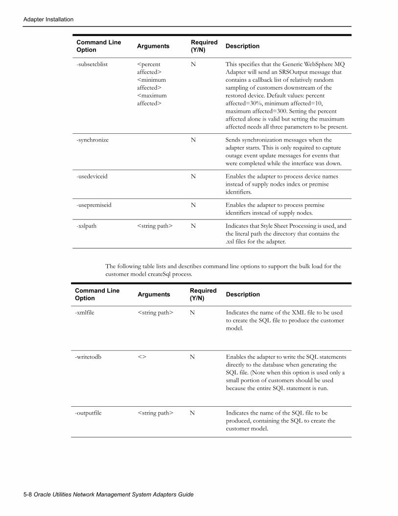
Adapter Installation
The following table lists and describes command line options to support the bulk load for the customer model createSql process.
Command Line Option
ArgumentsRequired (Y/N)
Description
-xmlfile <string path> N Indicates the name of the XML file to be used to create the SQL file to produce the customer model.
-writetodb <> N Enables the adapter to write the SQL statements directly to the database when generating the SQL file. (Note when this option is used only a small portion of customers should be used because the entire SQL statement is run.
-outputfile <string path> N Indicates the name of the SQL file to be produced, containing the SQL to create the customer model.
-subsetcblist <percent affected> <minimum affected> <maximum affected>
N This specifies that the Generic WebSphere MQ Adapter will send an SRSOutput message that contains a callback list of relatively random sampling of customers downstream of the restored device. Default values: percent affected=30%, minimum affected=10, maximum affected=300. Setting the percent affected alone is valid but setting the maximum affected needs all three parameters to be present.
-synchronize N Sends synchronization messages when the adapter starts. This is only required to capture outage event update messages for events that were completed while the interface was down.
-usedeviceid N Enables the adapter to process device names instead of supply nodes index or premise identifiers.
-usepremiseid N Enables the adapter to process premise identifiers instead of supply nodes.
-xslpath <string path> N Indicates that Style Sheet Processing is used, and the literal path the directory that contains the .xsl files for the adapter.
Command Line Option
ArgumentsRequired(Y/N)
Description
5-8 Oracle Utilities Network Management System Adapters Guide

Adapter Installation
Optionally, Configure the Adapter to Run with Another Instance of DBService
In $NMS_HOME/etc/system.dat, include the MQDBService as one of the services. Use the TCDBService entries as examples of how to set this up.
Note: If using a separate DBService, you must start the Generic WebSphere MQ Adapter with the “-custdbsname” command line parameter and use the MQDBService name as the argument.
Configure the WebSphere MQ Server• References to “Console Root” throughout this chapter refer to the highest level in the tree
displayed by the WebSphere MQ Explorer GUI.
Create New Queue Manager
1. From WebSphere MQ Explorer tree, select: Console Root ==> WebSphere MQ ==> Queue Managers ==> New ==> Queue Manager
• Queue Manager (name) = NMS_MGR.A
• Check “Make this the default Queue Manager” (indicating yes)
2. Click Next – use default settings (circular logging)
3. Click Next – use default settings (start queue manager)
4. Click Next – uncheck “create listener configured for TCP/IP”
Create New Queues (2)
1. From WebSphere MQ Explorer tree, select:
Console Root ==> WebSphere MQ ==> Queue Managers ==> NMS_MGR.A ==>Queues ==> New ==> Local Queue
• Queue Name = NMS.A.FROMNMS
2. Click OK – use all default settings
3. Click Console Root ==> WebSphere MQ ==> Queue Managers ==> NMS_MGR.A ==> Queues ==> New ==> Local Queue
• Queue Name = NMS.A.TONMS
4. Click OK – use all default settings
Note: At this point, the two new queues should be created. Check the status of each queue or put a test message into each queue by doing the following:
5. Select Console Root ==> WebSphere MQ ==> Queue Managers ==> NMS_MGR.A ==> Queues
This should display a list of queues.
6. Right click on the desired queue to bring up a menu containing selections for “Status” and “Put test message”.
Create Server Connection Channel
1. From WebSphere MQ Explorer tree, select:
Console Root ==> WebSphere MQ ==> Queue Managers ==> NMS_MGR.A ==> Advanced ==> Channels ==> New ==> Server Connection Channel
A dialog will display containing tabs for General, Extended, MCA, Exits, and SSL
Generic WebSphere MQ Adapter 5-9

Adapter Installation
• In the General tab, the Channel Name is SCH1
• In the MCA tab, the MCA User ID is the local login userid
2. Click OK – use all default settings
Note: At this point, the new server connection channel should be created. Check the status of the new server connection channel by doing the following:
3. Select Console Root ==> WebSphere MQ ==> Queue Managers ==> NMS_MGR.A ==> Advanced ==> Channels.
This should display a list of connection channels.
4. Right-click on the SCH1 channel to bring up a menu containing selections for “Status” and “Start” and “Stop”.
5. Select Start. The new server connection channel should display the message “The request to start the channel was accepted (amq4008)”.
Create New Queue Manager Listener Service
The default TCP/IP port for the default Queue Manager listener is 1414. Multiple listeners can be configured, but for simplicity, in this case, the original installation default listener for the default queue manager has been stopped. This frees up port 1414 for use by a new listener.
Stopping the Original Default Queue Manager Listener1. Select Console Root ==> WebSphere MQ Services (local) ==> (the original default queue
manager name).
This will cause a list of services to be displayed, one of which is the “listener” service.
2. Right-click on “listener ==> properties” and stop the listener.
3. Change the startup from Automatic to Manual.
This listener should no longer start-up at reboot.
Create New Queue Manager Listener for New Queue Manager
1. Select Console Root ==> WebSphere MQ Services (local) ==> NMS_MGR.A ==> New ==> Listener.
This will invoke a dialog to create a new “listener” service. This dialog will have three tabs, General, Recovery, and Parameters.
• The Parameters tab port number must be 1414.
• The General tab startup type should be “Automatic”.
2. Click the Start button on the General tab.
3. To check the status of the listener, select Console Root ==> WebSphere MQ Services (local) ==> NMS_MGR.A ==> Listener ==> Properties
Configure the MQ Client
Set Environment Variables
The environment configuration file (nms.rc), which is a data file listing Oracle Utilities Network Management System environment settings, should have the following:
export MQSERVER=SCH1/TCP/10.115.3.85
5-10 Oracle Utilities Network Management System Adapters Guide

Adapter Installation
The environment configuration file must also have two variables set to locate the .TAB file for WebSphere MQ. The .TAB must be copied to the MQ client from the MQ server host as specified by these variables.
Examples:
export MQCHLLIB=/users/proj/MQexport MQCHLTAB=AMQCLCHL.TAB
View this environment variable (to ensure that it’s correct) by typing in the following command: echo $MQSERVER
Test the Connection Between MQ Client and MQ Server
Test the Server Connection Channel (amqscnxc)
On the Unix command line, type in the following command:
/usr/mqm/samp/bin/amqscnxc -x 10.115.3.85 -c SCH1 NMS_MGR.A
where:
• -x is the IP address of the MQ Server host
• -c is the Server Connection Channel Name
• the third parameter is the desired Queue Manager Name
Test ‘Putting’ a message from Server to Client (amqsputc)
On the Unix command line, type in the following command:
/usr/mqm/samp/bin/amqsputc NMS.A.FROMNMS Sample AMQSPUT0 starttarget queue is NMS.A.FROMNMS
<MSG-FROM-SVR>VOILA</MSG-FROM-SVR> Sample AMQSPUT0 end
The message should appear in the queue named NMS.A.FROMNMS which can be viewed on the client using the MQ Explorer GUI at:
Console Root ==> WebSphere MQ ==> Queue Managers ==> NMS_MGR.A ==>Queues ==> NMS.A.FROMNMS ==> Browse Messages
Test ‘Getting’ a Message on Client from Server (amqsgetc)
First “get” the message just written
/usr/mqm/samp/bin/amqsgetc NMS.A.FROMNMS Sample AMQSGET0 start message <<MSG-FROM-SVR>VOILA</MSG-FROM-SVR>> no more messages Sample AMQSGET0 end
Test ‘Putting’ a Message from Client to Server using WebSphere MQ GUI1. Select Console Root ==> WebSphere MQ ==> Queue Managers ==> NMS_MGR.A ==>
Queues ==> NMS.A.TONMS ==> Put Test Message
2. Paste the following into “Message Data”:
<MSG-FROM-CLNT>VOILA</MSG-FROM-CLNT>
3. Click OK.
The following message should be displayed: “The test message was put successfully (amq4016)”.
Generic WebSphere MQ Adapter 5-11

High Availability
Test ‘Getting’ a Message on Server from Client (amqsgetc)
On the Unix command line:
/usr/mqm/samp/bin/amqsgetc NMS.A.TONMS Sample AMQSGET0 start message <<MSG-FROM-CLNT>VOILA</MSG-FROM-CLNT>> no more messages Sample AMQSGET0 end
High AvailabilityThe goal of the Oracle Utilities Network Management System MQ XML adapter redundancy is to provide assured message receipt and delivery between the Oracle Utilities Network Management System services and the WebSphere MQ queues. There are a number of availability approaches that could be utilized, with potentially different approaches being used for each system to be interfaced. The purpose of this section is to describe different availability approaches that can be used with the adapter.
ClusteringOne approach for high availability is to utilize WebSphere MQ clustering on Windows where persistent queues would be used. The adapter is then responsible for maintaining connection to InterSys. All messages would be persisted to one physical disk location, where either redundant Oracle Utilities Network Management System Generic WebSphere MQ Adapter would have access to the same message.
Non-Redundant Queue ApproachThis would be a classical implementation using WebSphere MQ. A single copy of the Oracle Utilities Network Management System Generic WebSphere MQ Adapter would be used to retrieve information from a single (non-redundant) set of message queues.
This approach is the simplest and most common way to implement WebSphere MQ queues for an application. However, a hard failure of the adapter or its server could result in message losses.
Synchronization ProcessIn the case in which both adapter servers are down, the Generic WebSphere MQ Adapter provides a synchronization process on startup by specifying –synchronize command line option. This will retrieve all events information from OPS and put them on the queue with topic_type = ‘TRBL_UPDATE’ in <PostSrsOutput_001> message with <srsOutputMsgType>1</srsOutputMsgType> and <description>SYNCHRONIZE</description>. This synchronization can also be triggered again by issuing the following command from the Unix server command prompt:
Action any.mq* synchronize
The synchronized messages will include the latest status of all active events and completed/cancelled events in the past N days, where N is the number of days since the adapter was last running.
TroubleshootingHigh-level messages are typically used within Oracle Utilities Network Management System to permit one process to control another process. There are no special high-level messages that would be required for this adapter.
Note that doing an Action any.any stop will stop the adapter, which needs to be taken into consideration for administering the adapter when starting and stopping it.
5-12 Oracle Utilities Network Management System Adapters Guide

Performance
Supported high level messages include the following:
• report
• debug <debug level>
• stop
Example usage: Action any.mqseriesgateway report
PerformanceThis interface is intended to provide for high performance as needed to process frequent message exchange such as in the case of trouble calls during a storm. In order to provide optimum performance, there are aspects of both implementation and usage. Aspects of usage include:
1. Sending multiple trouble calls together in a single message when possible will improve the call volume.
2. Providing a valid device identifier (supply node) on each trouble call.
3. Avoiding unnecessary queries within Oracle Utilities Network Management System, which might otherwise degrade overall system performance either due to locking, CPU utilization and/or disk access.
4. Using a customer account (service account), or premiseId as apposed to the custDeviceIdx with a supply node, will slow down the overall performance of trouble call processing and potentially outage prediction.
The following aspects of implementation can optimize performance:
It is assumed that incoming XML messages are well formed, bypassing the validation step. It is assumed that the sender provided well-formed XML, which was transmitted using reliable communication mechanisms. The actual validation test is whether or not the code that internally parses a message can extract a sufficient set of parameters to make an InterSys request. XML that is not well formed will typically generate an error. It should also be noted that XML validation does not necessarily guarantee valid information provided by an external system. If this generates an error in the adapter, it will be generate an error.
Use of multiple threads within the adapter, permitting parallel processing. This makes it possible to process multiple requests concurrently, providing the potential to increase performance.
Functional RequirementsThe purpose of this section is to describe the desired functionality. Key requirements include the following:
• Get customer(s) query using fuzzy keys (as through call entry application).
• Get customer outage status information, which would indicate whether or not a customer is part of an existing outage.
• Get customer outage history, which would provide the available outage history for a customer who may have been part of an old outage event.
• Create incident, to send trouble calls to Oracle Utilities Network Management System for outage analysis.
• Add, remove, and update condition. One example of possible usage would be to get tags from SCADA for display within Oracle Utilities Network Management System.
• Get conditions for a specified device as maintained within Oracle Utilities Network Management System.
Generic WebSphere MQ Adapter 5-13

Data Flows
• Create, Delete, and Update customer information, as might typically be used by a Customer Information System (CIS) to maintain customer information within Oracle Utilities Network Management System. Support a mechanism that will provide a means of generating a large number of customer transactions to initially load the customer model.
• Check interface/InterSys status, permitting an external system to see whether or not the adapter is currently active and whether or not Oracle Utilities Network Management System is active.
• Report Current outage status to indicate current state of an outage.
• Report Crew outage states to indicate crew events that may change the state of an outage in Oracle Utilities Network Management System.
• Receive customer disconnect and reconnect indications to identify if the utility has purposely disconnect power or restored power for a customer.
• Network trace including planned outage and current feeder request.
• SQL Queries and Database transactions to get reports or manipulate specific customer specific tables.
• Support for style sheet translation on incoming and outgoing XML messages.
• Support for external notification when the status of a device changes such as open or close.
• Synchronize outage status between Oracle Utilities Network Management System and external system.
• Create area summary list
• Create callback list
Design OverviewThe general approach is to build an adapter process that passes messaging between the Isis and WebSphere MQ messaging systems. Messages sent and received using WebSphere MQ will be formatted in XML. The types of messaging that will be supported include the following:
• Asynchronous publish from Oracle Utilities Network Management System to WebSphere MQ (using ‘fire and forget’ pattern)
• Asynchronous publish from WebSphere MQ to Oracle Utilities Network Management System (using ‘fire and forget’ pattern)
• Request/reply from WebSphere MQ to Oracle Utilities Network Management System (the requestor can process this either synchronously or asynchronously)
As the Oracle Utilities Network Management System currently supports a large number of messages internally, the principle of this interface is to externalize support for a key subset of those messages through the WebSphere MQ adapter.
Data Flows
OverviewThe purpose of this section is to describe the information flows that are relevant to this interface. The details of each of these flows and associated XML formats are provided in the appendices.
All flows are formatted using XML, with specific XML definitions defined as to be consistent with Oracle Utilities Network Management System product direction. XML messages will provide well-formed XML, without a requirement for validation, as validity will be the responsibility of the
5-14 Oracle Utilities Network Management System Adapters Guide

Data Flows
sender. Consequentially, there is also no requirement for the specification of DTDs or XML Schema definitions. Specific XML requirements are defined in the appendixes of this document.
Create IncidentThis is an asynchronous input to the adapter to report trouble calls. Internally the JMS::sendJMSinput method is used to send the trouble call to Oracle Utilities Network Management System. This interface supports a variety data that might be input on a trouble call.
This will be sent using an asynchronous fire and forget.
Adapter can also process fuzzy call with street intersection data. This requires att_street_segment and att_street_intersect tables to be populated.
Note: Performance is optimized when the customer supply node is identified.
Get Customer Outage StatusThis is a request/reply interface that is used to obtain the current status of a customer. The information returned includes:
• Whether or not the customer is part of an existing outage
• Estimated restoration time
• Whether or not customer is part of a planned outage
This will be processed using an asynchronous inquiry. It should be noted that several queries are required to collect this information, it will degrade overall performance in storm situation.
Get Customer Outage HistoryThis is a request/reply interface that is used to obtain customer call and outage history.
• Call history
• Outage history
This message will be processed using an asynchronous inquiry. It should be noted that several queries are required to collect this information, it will degrade the overall performance in storm situation. This history is supply based on the current Ops database, and will not get history from any historical database.
Create, Delete, Update, Get ConditionThis interface would be used to report tags and other types of conditions. Conditions are objects that describe and manage important information associated with objects that are defined within the Oracle Utilities Network Management System model. Subclasses of the “condition” class include “tag” and “note”, or any other configured condition in Oracle Utilities Network Management System.
This message is an asynchronous input to the adapter.
Outage Status This interface is an asynchronous output from the adapter used to publish SRS output messages. SRS output messages describe creation, update, and closure of information related to outages. If TRBL_ERT_UPDATE message type is configured in the mq_adapter_config table, then global ERT changes from Stormman will trigger <postSrsOutput_001> message with type = 20 to be published for each event. For performance considerations, type = 20 message only has limited information.
Generic WebSphere MQ Adapter 5-15
Data Flows
Create, Delete, Update, Get CustomerThis is an asynchronous input interface used to report updates to the customer data model. These updates may be the addition, modification or deletion of a customer. To get information for an existing customer, the get verb is supported in order to retrieve this information. In the event of an update, only the modified information needs to be supplied. Internally this will use the DBS::sql method to perform updates to the appropriate tables that define the customer data model. It is assumed that CES_CUSTOMER and CUSTOMER_SUM are implemented as views, and the Oracle Utilities Network Management System MultiSpeak-based customer model is utilized.
This interface is implemented in a manner to provide extensions over the capabilities of MultiSpeak, including multiple meters and/or transformers for a service location. The interface uses the internal service point entity to manage these relationships.
Customer update can be configured to use separate DBService by using command line option –custdbsname <DBSNAME> to improve overall performance. This requires the server side to have an instance of DBService reserved for this purpose.
There is a new command line option available –custsqlbundle which will greatly improve the performance for DELETECREATE/CUSTOMER request.
Note: It will be necessary to have JMService update its internal cache periodically. This will be triggered by the adapter nightly by the defined recache period that is supplied to the adapter. The default value is 24 hours and can be changed through –recache <HOURS>. Re-cache can also be configured to run at specific hour and minute by specifying –recachehour <HOUR> and -recacheminute <MINUTE>. These two command line options will override –recache <HOURS> option. The recache function can be disabled by using –nosndrecache option.
SQL TransactionsThis is an asynchronous input interface is used to send SQL transactions to Oracle Utilities Network Management System. This internally uses the DBS::sql method. This interface is activated by the – sql command line option.
WARNING: This interface, if activated, is a potential security issue in non-trusted environments, as it would be possible to execute destructive transactions against the Oracle Utilities Network Management System database.
WARNING: This interface, if activated and used inappropriately, can be a source of system performance degradation or denial of service. This would be the case if long duration transactions were run against the Oracle Utilities Network Management System database, especially if done against key Oracle Utilities Network Management System tables.
SQL QueryThis is a request/reply interface that is used to perform an SQL query on Oracle Utilities Network Management System and return the resulting selection set. The DBS::query method is used internally. The returned XML is formatted using appropriate tags, using column names, and row delimiters.
WARNING: This interface, if activated and used inappropriately, can be a source of system performance degradation or denial of service. This would be the case if long duration queries were run against the Oracle Utilities Network Management System database, especially if done against key Oracle Utilities Network Management System tables.
5-16 Oracle Utilities Network Management System Adapters Guide

Data Flows
Status CheckThis is a request/reply interface that is used to check the status of the Generic WebSphere MQ Adapter.
ErrorsErrors detected will be asynchronously reported on the defined error queue. An error queue will be as define per the reply queue for any out going message. If there is no reply queue, the default queue will be used to supply the error messages to.
Customer Disconnect / Reconnect.This information flow is implemented as an asynchronous request for disconnecting or reconnecting customers, indicating which customers have had power disconnected or reconnected by the utility. The customers who have been disconnected will not be seen by Oracle Utilities Network Management System call taking applications, as these customers have purposely been disconnected by the utility for payment reasons. In order for these customers to be ignored from call taking applications that will be using the CreateIncident flow defined in this document, the checkCutoff flag for customers that call in should be used for JMService to be notified to check for the disconnected customers. If these systems know that the customers are disconnected, calls for these customers only need to use the checkCutoff flag.
Crew Outage Status ChangesThe purpose of this section is to provide crew states that may or may not transition an outage state change in Oracle Utilities Network Management System. Oracle Utilities Network Management System currently provides crew state changes for an outage via a CrewMessage. The CrewMessage contains the following message types for crew messages. Each message type identified below also provides whether or no the message could change the status of the outage.
Crew Message TypeClasses APIs available in
Potentially generates outage state change
Description.
INVALID None NO Invalid message was sent. Unsupported message for all crew APIs
SET_CONST None NO Sets static constant(s) for the Crew class, which will make non-standard functionality of the crew classes be supported.
CLEAR_CONST None NO Remove a static constant that has been set. This may make some supported functionality of the crew classes’ disabled.
AVAIL_FOR_OP Crew NO
UNAVAIL_FOR_OP Crew NO
CREATED Crew NO
DELETED Crew NO
EDITED Crew NO
ACTIVATED Crew NO
Generic WebSphere MQ Adapter 5-17

Data Flows
These changes may affect the status of the outage, or just the status of a crew. Via configuration of the mq_adapter_config table, any crew state change may trigger the creation of a PostSrsOutputStatus_001 XML message. This message will be identical in format to the PostSrsOutput_001 XML message, except that it will be triggered by the configure crew message type as previously defined. If the configuration for the crew message type is made, any queue can be used to put the PostSrsOutputStatus_001 message in.
Note: The crew message may not affect the current state transition of the outage, and may provide redundant data. In order to avoid un-necessary overhead of providing SRSOutput status information for non-required crew states, it is highly recommended that only the minimal crew states that are needed for the outage state changes are used in order to get the PostSrsOutputStatus_001 XML message. This flow will have to go to JMService to regenerate the outage information.
DEACTIVATED Crew NO
ASSIGNED CrewAssignment YES
UNASSIGNED CrewAssignment YES
DISPATCHED CrewDispatch YES
UNDISPATCHED CrewDispatch YES
RELOCATE CrewDispatch YES
AVAILABLE Crew NO
UNAVAILABLE Crew NO
ASSIGNMENT_CHANGED CrewAssignment YES
DISPATCH_CHANGED CrewAssignment YES
ARRIVED CrewDispatch YES
UNARRIVED CrewDispatch YES
TEMP_ZONE_CHANGE Crew NO
UPDATE_SCHEDULE Crew NO
SUSPENDED CrewAssignment YES
CASE_NOTES_INFO_CHANGED
Crew NO
CREW_REQUEST_ADD CrewRequest NO
CREW_REQUEST_EDIT CrewRequest NO
CREW_REQUEST_DELETE CrewRequest NO
Crew Message TypeClasses APIs available in
Potentially generates outage state change
Description.
5-18 Oracle Utilities Network Management System Adapters Guide

Data Flows
An example for configuring the receipt of a PostSrsOutputStatus_001 is provided below.
INSERT INTO mq_adapter_config VALUES ('OMS_OUTAGE_STATUS', 2, 'PostSrsOutputStatus_001', 'DISPATCHED', '', '', 1);
In this example, if a message type of “DISPATCHED” is received by the adapter, JMService will (via JMS::getEventInfo()) be requested for the current event status of the outage. The outage status can be retrieved via the Crew with the current outage data; a PostSrsOutputStatus_001 XML message will be generated to send to the OMS_OUTAGE_STATUS queue. Note that any queue can be defined to publish the Outage Status to. This will be configurable based on the number of configuration parameters for the PostSrsOutputStatus_001 XML message. Whichever crew message types should trigger the creation of the XML message, each one (message type and put queue) will need to be identified and defined in the mq_adapter_config table. Please refer to PostSrsOutput_001 XML message for the data content of the PostSrsOutputStatus_001 message.
The purpose of this information flow is to provide crew outage status messages when ever a crew is Dispatched, Un-Dispatched, Assigned, or Un-Assigned from an event. In order to provide the crew outage status change for the events, this flow is required. This will be an asynchronous event that will provide the crew outage status changes to any interface that may require this information.
Sending Crew Updates / Getting Crew (Request / Reply) InformationWhen an external system needs to get crew details for one Crew, or all Crews, or the Crew needs to be indicated assigned, un-assigned, dispatched, un-dispatched, arrived, available, unavailable, active, in-active, or suspended from an event in or independent from an event in Oracle Utilities Network Management System; the external system will send a crew update message with the event id to Oracle Utilities Network Management System. The VERB of the CrewUpdate_001 XML message will indicate the state or action to be triggered by the message. Creating, deleting and editing crews is also supported by this flow.
Published Crew Information Updates to an External SystemWhen a crew is assigned, un-assigned, dispatched, un-dispatched, arrived, suspended, created, deleted, or edited in Oracle Utilities Network Management System; the system will broadcast this information to any external system that would be interested in receiving this information about the crew.
Network Trace Includes Planned Outage Request and Current Feeder RequestOracle Utilities Network Management System has the ability to send all supply nodes back for a specific device (planned outage request). Oracle Utilities Network Management System can also send back feeder, substation and control zone information back for a specific supply node (current feeder request). To enable this function, one line needs to be added to MQ_ADAPTER_CONFIG table and specify ‘-connectivitytrace’ command line option:
insert into mq_adapter_config values ('REQUEST_TRACE',3, 'TraceNetwork_001','TraceNetwork_001',null,'REPLY_TRACE',1);
Generic WebSphere MQ Adapter 5-19

Information Model
Area SummaryThe MQ Adapter will respond to a request for an area summary. The reply message will contain information that is available in the Performance Mart database. A synonym will be created to make this data available in the Ops database. The MQ Series Adapter will query this table and send back the information.
This will be a request/reply data flow. The external system must request an outage summary for the MQ Adapter to send a response. The areas that are to be summarized will exactly match some level(s) as defined in the Performance Mart database. The areas that are returned will be the Area Control Zones with recognized active outages. The control zone level of the included areas can be configured through the command line.
Callback ListThe callback list message will use the same body as the Post SRSoutput message. It will have a different noun and verb.
There are two types of callback list. One contains in the incident list all of the callers who have requested a callback. This message will have a verb of REQUESTED and a noun of CALLBACKLIST. The second type of callback list is a relatively random sampling of customers downstream of the restored device. This message will have a verb of SUBSET and a noun of CALLBACKLIST.
There are configurable parameters that will set the maximum and minimum percentage of affected customers who will be included in the SUBSET callback list. The maximumCallbackSample and minimumCallbackSample for the subset callback can be set through the srs_rules table. These parameters will default to 50 and 4 percent respectively if not configured explicitly. Both types of callback lists use the same format found in PostSrsOutput_001.xsd.
Information ModelThis section provides an overview of the logical information model supported by this interface. The key objects supported by this interface include:
• Customers, which are defined using accounts, service locations and meters. This model is based upon the MultiSpeak model. Typically, as a practical note, the custId identifier may in fact be the same as the account number. Some extensions to the MultiSpeak model are used as required to address issues that are otherwise not addressed by MultiSpeak. The support of a bulk load process that reads an XML file, with defined customers to create the model. This process (createSql) can be run to generate the SQL to be run on the production servers, or can directly create the customers.
• Trouble calls are also referred to as incidents with in Oracle Utilities Network Management System. An incident is typically related to a customer, who in turn is related to a device. In the absence of a correlation to a device, a trouble call is classified as a ‘fuzzy’ call, which differentiates it from a call that can be directly correlated to the electrical distribution network.
• Outages, which are a consequence of the correlation of incidents. Outages are one form of an event that is managed by JMService. Some events are non-outage events, such as power quality. The type of call that is provided can identify such non-outage and outage events. Each call needs to be identified with a trouble code, which will determine the type of call that JMService will generate with in Oracle Utilities Network Management System.
• Devices, which are part of the electrical distribution network. Customers, outages and conditions may have relationships to devices. Typically customers are related to transformer devices. Outages are typically related to switch, fuse or transformer devices.
• Conditions (which can be specialized within Oracle Utilities Network Management System for the management of information such as tags, notes, etc.)
5-20 Oracle Utilities Network Management System Adapters Guide
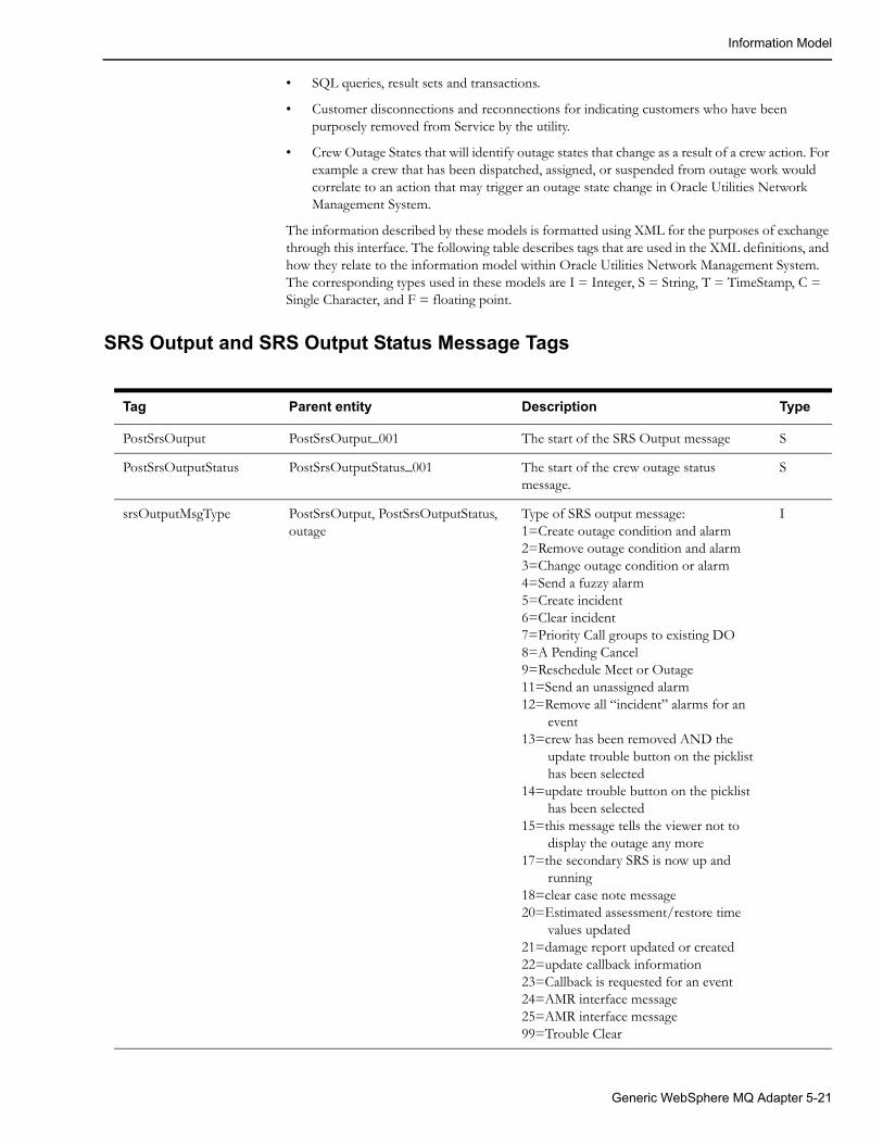
Information Model
• SQL queries, result sets and transactions.
• Customer disconnections and reconnections for indicating customers who have been purposely removed from Service by the utility.
• Crew Outage States that will identify outage states that change as a result of a crew action. For example a crew that has been dispatched, assigned, or suspended from outage work would correlate to an action that may trigger an outage state change in Oracle Utilities Network Management System.
The information described by these models is formatted using XML for the purposes of exchange through this interface. The following table describes tags that are used in the XML definitions, and how they relate to the information model within Oracle Utilities Network Management System. The corresponding types used in these models are I = Integer, S = String, T = TimeStamp, C = Single Character, and F = floating point.
SRS Output and SRS Output Status Message Tags
Tag Parent entity Description Type
PostSrsOutput PostSrsOutput_001 The start of the SRS Output message S
PostSrsOutputStatus PostSrsOutputStatus_001 The start of the crew outage status message.
S
srsOutputMsgType PostSrsOutput, PostSrsOutputStatus, outage
Type of SRS output message:1=Create outage condition and alarm 2=Remove outage condition and alarm3=Change outage condition or alarm4=Send a fuzzy alarm5=Create incident6=Clear incident7=Priority Call groups to existing DO8=A Pending Cancel9=Reschedule Meet or Outage11=Send an unassigned alarm 12=Remove all “incident” alarms for an
event 13=crew has been removed AND the
update trouble button on the picklist has been selected
14=update trouble button on the picklist has been selected
15=this message tells the viewer not to display the outage any more
17=the secondary SRS is now up and running
18=clear case note message20=Estimated assessment/restore time
values updated21=damage report updated or created22=update callback information23=Callback is requested for an event24=AMR interface message25=AMR interface message99=Trouble Clear
I
Generic WebSphere MQ Adapter 5-21

Information Model
district PostSrsOutput, PostSrsOutputStatus, outage
District name of the outage device S
office PostSrsOutput, PostSrsOutputStatus, outage
Office name of the outage device S
circuit PostSrsOutput, PostSrsOutputStatus, outage
Circuit name of the outage device S
feeder PostSrsOutput, PostSrsOutputStatus, outage
Feeder name of the outage device S
Ncg PostSrsOutput, PostSrsOutputStatus, outage
ID of the control zone of the outage device
I
partition PostSrsOutput, PostSrsOutputStatus, outage
Partition ID typically identifies the map sheet on which a device is associated
I
appliedRule PostSrsOutput, PostSrsOutputStatus, outage
Rule number used by SRS to determine outage device
I
numb PostSrsOutput, PostSrsOutputStatus, outage
Internal identifier for each outage record I
ruleSet PostSrsOutput, PostSrsOutputStatus, outage
Name of active rule set used by SRS to process outage
S
eventCls PostSrsOutput, PostSrsOutputStatus, outage
Event class. Class 800 indicates an outage event. Part of the event handle.
I
eventIdx PostSrsOutput, PostSrsOutputStatus, outage
Event index, part of the event handle that uniquely identifies event in conjunction with the eventCls.
I
eventApp PostSrsOutput, PostSrsOutputStatus, outage
Event app, part of the event handle that uniquely identifies event in conjunction with the eventCls and eventIdx.
I
alarmCls PostSrsOutput, PostSrsOutputStatus, outage
Alarm class, part of alarm handle. Used to uniquely identify rows on work agenda
I
alarmIdx PostSrsOutput, PostSrsOutputStatus, outage
Alarm index, part of alarm handle. Used to uniquely identify rows on work agenda
I
deviceCls PostSrsOutput, PostSrsOutputStatus, outage
Class or outage device. Identifies the type of device that failed.
I
deviceIdx PostSrsOutput, PostSrsOutputStatus, outage
Used in conjunction with the deviceCls to form the device handle, which uniquely identifies a device.
I
deviceAlias PostSrsOutput, PostSrsOutputStatus, outage
Name of outage device, as defined in the ALIAS_MAPPING table.
S
deviceApp PostSrsOutput, PostSrsOutputStatus, outage
Used in conjunction with the deviceCls and deviceIdx to form the device handle, which uniquely identifies a device.
deviceApp
cause PostSrsOutput, PostSrsOutputStatus, outage
Outage cause (TROUBLE_CALL, FAULT_INDICATOR or blank)
S
Tag Parent entity Description Type
5-22 Oracle Utilities Network Management System Adapters Guide

Information Model
description PostSrsOutput, PostSrsOutputStatus, outage
Short description based on status S
troubleCode PostSrsOutput, PostSrsOutputStatus, outage
Entered trouble code or combination from all calls
S
troubleQueue PostSrsOutput, PostSrsOutputStatus, outage
Dispatcher queue for outage S
status PostSrsOutput, PostSrsOutputStatus, outage
Alarm state name S
operatorComment PostSrsOutput, PostSrsOutputStatus, outage
Operator entered comment S
tags PostSrsOutput, PostSrsOutputStatus, outage
Y if tags exist
N if no tags exist
X if tags are not checked
C
estSource PostSrsOutput, PostSrsOutputStatus, outage
Source of estimated restoration time:
C=crew (manually entered)
S=Storm Management (regular)
G=Storm Management globally applied ERT
D=Storm Management globally applied ERT delay
P=Storm Management non-published ERT
O=Storm Management (crew dispatched/onsite)
M=Storm Management calculated ERT exceeded allowed maximum
I=Initial ERT
N=none
C
externalId PostSrsOutput, PostSrsOutputStatus Identifier for event supplied by an external system.
I
crewId PostSrsOutput, PostSrsOutputStatus, outage
Crew(s) assigned to outage I
firstIncTime PostSrsOutput, PostSrsOutputStatus, outage
Time of first reported incident. T
firstCrewTime PostSrsOutput, PostSrsOutputStatus, outage
Time of first dispatched crew. T
crewOnSiteTime PostSrsOutputStatus Time of crew arrival T
estRestTime PostSrsOutput, PostSrsOutputStatus, outage
Estimated restoration time. T
Tag Parent entity Description Type
Generic WebSphere MQ Adapter 5-23

Information Model
outageTime PostSrsOutput, PostSrsOutputStatus, outage
Time the outage began. T
jobCompletionTime PostSrsOutput, PostSrsOutputStatus, outage
Time outage was completed. T
restoreTime PostSrsOutput, PostSrsOutputStatus, outage
Time the outage was restored. T
srsCondStatus PostSrsOutput, PostSrsOutputStatus, outage
Outage status codes:
0=no outage
1=probable service outage
2=probable device outage
3=real service outage
4=real device outage
7=non outage
8=critical meet
9=future meet
10=confirmed service outage
11=confirmed secondary outage
12=additional alarm
13=probable momentary outage
14=real momentary outage
15=planned outage
I
condPhases PostSrsOutput, PostSrsOutputStatus, outage
Bitmask to identify affected phases I
customersOut PostSrsOutput,
PostSrsOutputStatus,
outage
Number of customers affected by an outage.
I
srsPriority PostSrsOutput, PostSrsOutputStatus, outage
Number of priority calls, may be redefined by configuration
I
custCall PostSrsOutput, PostSrsOutputStatus, outage
Number of customers affected by an outage that have called.
I
priW PostSrsOutput, PostSrsOutputStatus, outage
Number of wire related calls, may be redefined by configuration
I
priSW PostSrsOutput, PostSrsOutputStatus, outage
Number of service wire related calls, may be redefined by configuration
I
priP PostSrsOutput, PostSrsOutputStatus, outage
Number of pole problem calls, may be redefined by configuration
I
priE PostSrsOutput, PostSrsOutputStatus, outage
Number of emergency calls, may be redefined by configuration
I
Tag Parent entity Description Type
5-24 Oracle Utilities Network Management System Adapters Guide

Information Model
custCrit PostSrsOutput, PostSrsOutputStatus, outage
Number of affected critical customers I
crit1 PostSrsOutput, PostSrsOutputStatus, outage
Number of category 1 customers that called, as determined by configuration
I
crit2 PostSrsOutput, PostSrsOutputStatus, outage
Number of category 2 customers that called, as determined by configuration
I
crit3 PostSrsOutput, PostSrsOutputStatus, outage
Number of category 3 customers that called, determined by configuration
I
critK PostSrsOutput, PostSrsOutputStatus, outage
Affected category K (KEY) customer, may be redefined by configuration
I
critC PostSrsOutput, PostSrsOutputStatus, outage
Affected category C (CRITICAL) customer, may be redefined by configuration
I
critD PostSrsOutput, PostSrsOutputStatus, outage
Affected category D customer, may be redefined by configuration
I
critTot PostSrsOutput, PostSrsOutputStatus, outage
Total number of critical customers, recognizing that a customer is counted only once even though it may belong to more than one category
I
revenue PostSrsOutput, PostSrsOutputStatus, outage
Revenue of the total customers from customer_sum
revenue
customerName PostSrsOutput, PostSrsOutputStatus, outage
Used for fuzzy calls S
addrBuilding PostSrsOutput, PostSrsOutputStatus, outage
Used for fuzzy calls S
addrStreet PostSrsOutput, PostSrsOutputStatus, outage
Used for fuzzy calls S
addrCity PostSrsOutput, PostSrsOutputStatus, outage
Used for fuzzy calls S
customerPhone PostSrsOutput, PostSrsOutputStatus, outage
Used for fuzzy calls S
xRef PostSrsOutput, PostSrsOutputStatus, utage
X reference coordinate F
yRef PostSrsOutput, PostSrsOutputStatus, outage
Y reference coordinate F
sheetNum PostSrsOutput, PostSrsOutputStatus, outage
Number of switching sheet associated with a planned outage.
I
dispAddress PostSrsOutput, PostSrsOutputStatus, outage
Dispatch address, first incident if probable service outage, feeder name if no incidents or probable device outage
S
groupType PostSrsOutput, PostSrsOutputStatus, outage
GRP is manually grouped, REL if related S
Tag Parent entity Description Type
Generic WebSphere MQ Adapter 5-25
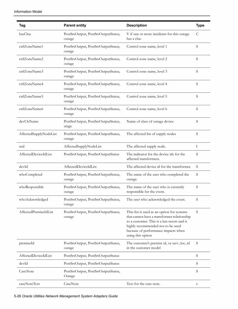
Information Model
hasClue PostSrsOutput, PostSrsOutputStatus, outage
Y if one or more incidents for this outage has a clue
C
ctrlZoneName1 PostSrsOutput, PostSrsOutputStatus, outage
Control zone name, level 1 S
ctrlZoneName2 PostSrsOutput, PostSrsOutputStatus, outage
Control zone name, level 2 S
ctrlZoneName3 PostSrsOutput, PostSrsOutputStatus, outage
Control zone name, level 3 S
ctrlZoneName4 PostSrsOutput, PostSrsOutputStatus, outage
Control zone name, level 4 S
ctrlZoneName5 PostSrsOutput, PostSrsOutputStatus, outage
Control zone name, level 5 S
ctrlZoneName6 PostSrsOutput, PostSrsOutputStatus, outage
Control zone name, level 6 S
devClsName PostSrsOutput, PostSrsOutputStatus, utage
Name of class of outage device S
AffectedSupplyNodeList PostSrsOutput, PostSrsOutputStatus, outage
The affected list of supply nodes S
snd AffectedSupplyNodeList The affected supply node. I
AffectedDeviceIdList PostSrsOutput, PostSrsOutputStatus The indicator for the device ids for the affected transformers.
S
devId AffectedDeviceIdList The affected device id for the transformer. S
whoCompleted PostSrsOutput, PostSrsOutputStatus, outage
The name of the user who completed the outage.
S
whoResponsible PostSrsOutput, PostSrsOutputStatus, outage
The name of the user who is currently responsible for the event.
S
whoAcknowledged PostSrsOutput, PostSrsOutputStatus, outage
The user who acknowledged the event. S
AffectedPremiseIdList PostSrsOutput, PostSrsOutputStatus, outage
This list is used as an option for systems that cannot have a transformer relationship to a customer. This is a last resort and is highly recommended not to be used because of performance impacts when using this option
S
premiseId PostSrsOutput, PostSrsOutputStatus, outage
The customer’s premise id, or serv_loc_id in the customer model
S
AffectedDeviceIdList PostSrsOutput, PostSrsOutputStatus S
devId PostSrsOutput, PostSrsOutputStatus S
CaseNote PostSrsOutput, PostSrsOutputStatus, Outage
S
caseNoteText CaseNote Text for the case note. s
Tag Parent entity Description Type
5-26 Oracle Utilities Network Management System Adapters Guide

Information Model
Note: The following tags appear in <PostSrsOutput_001> message only if the ‘-includeincident’ command line option is used. Oracle recommends against using this option.
IncidentList PostSrsOutput, PostSrsOutputStatus, outage
Incident IncidentList
incTroubleCode Incident S
incDevice Incident S
incAccount Incident S
incCustDeviceCls Incident I
incCustDeviceIdx Incident I
incCustName Incident S
incAddress Incident S
incStreet Incident S
incCity Incident S
incPhone Incident S
incIncidentTime Incident S
incComment Incident S
incCallbackLate Incident S
incExternaId Incident S
incCallCancel Incident S
incLifeSupport Incident S
incCustPriority Incident S
incMeterId Incident S
incGeneralArea Incident S
incCustOrderNum Incident S
incDrvInst Incident S
incCallbackRequest Incident S
incCustCritical Incident S
incAlternatePhone Incident S
incCserName Incident S
incXRef Incident F
incYRef Incident F
incEventCls Incident I
Tag Parent entity Description Type
Generic WebSphere MQ Adapter 5-27

Information Model
Note: Many values, names and usages are configurable and vary between implementations. The details and description of configuration options are outside the scope of this document.
Note: For performance reasons the type 20(TRBL_ERT_UPDATE) message contains limited information. The available fields are: <srsOutputMsgType>, <eventIdx>, <estRestTime> and <estSource>. Other fields are either NULL or 0.
Customer Message TagsRefer to the Oracle Utilities Network Management System Customer Data Model specification.
Note: The bulk load of customers can be accomplished by running the createSql.exe file that will create .sql file to be run through ISQL.ces, which will populate the customer model. The createSql file should be provided the following command line options to create the sql. (IE. CreateSql –xmlfile create_customers.sql –outputfile product_customer_data.sql.) The –writetodb command can be provided to write the customers directly through to the database with out having to run ISQL.ces < product_customer_data.sql.
Trouble Call Message Tags
incEventIdx Incident I
Tag Parent entity Description Type
Tag Parent Description
Incident
troubleCode Incident
device Incident
account Incident
custDeviceCls Incident
custDeviceIdx Incident
name Incident
address Incident
city Incident
phone Incident
incidentTime Incident
comment Incident
callbackLate Incident
externalId Incident
callCancel Incident Deprecated and project specific
5-28 Oracle Utilities Network Management System Adapters Guide

Information Model
lifeSupport Incident
custNone Incident
custPriority Incident
custPhoneArea Incident
callId Incident
meterId Incident
custLastName Incident
generalArea Incident
custOrderNum Incident
drvInst Incident
addrBuilding Incident
addrStreet Incident
addrCity Incident This is also used in fuzzy calls to get a better indication of which intersection point should be used.
meetTime Incident
meetType Incident
cidAlias Incident
powerUp Incident
cancelCall Incident Deprecated and project specific
callbackRequest Incident
callbackTime Incident
custIntrX Incident
custIntrY Incident
updateExistingInc Incident
custCritical Incident
alternatePhone Incident
userName Incident
checkCutoff Incident
xRef Incident
yRef Incident
custPhoneUpdate Incident
streetNameA Incident Used to indicate a street name for a fuzzy call
streetNameB Incident Used to indicate a street name for a fuzzy call.
Tag Parent Description
Generic WebSphere MQ Adapter 5-29

Information Model
meterId Incident
custLastName Incident
generalArea Incident
custOrderNum Incident
drvInst Incident
addrBuilding Incident
addrStreet Incident
addrCity Incident This is also used in fuzzy calls to get a better indication of which intersection point should be used.
meetTime Incident
meetType Incident
cidAlias Incident
powerUp Incident
cancelCall Incident Deprecated and project specific
callbackRequest Incident
callbackTime Incident
custIntrX Incident
custIntrY Incident
updateExistingInc Incident
custCritical Incident
alternatePhone Incident
userName Incident
checkCutoff Incident
xRef Incident
yRef Incident
custPhoneUpdate Incident
streetNameA Incident Used to indicate a street name for a fuzzy call
streetNameB Incident Used to indicate a street name for a fuzzy call.
Tag Parent Description
5-30 Oracle Utilities Network Management System Adapters Guide

Information Model
Crew Message Tags
premiseId Incident This is the premiseId (serv_loc_id) for the customer. This XML tag should only be used as a last option if supply node or customer account number cannot be used with a call. This field incurs additional performance issues if used, and is highly recommended not to use it as an option for processing trouble calls.
controlZoneName Incident If the control zone name is passed with the call, it will be used to append control zone information with the call to be placed at this control zone within JMService. This would be useful in cases where customers are not yet modeled in Oracle Utilities Network Management System, and calls would want to be placed as close to the lowest control zone as possible.
eventCls Incident Related event class. Used for canceling or updating outages.
eventIdx Incident Related event index. Used for canceling or updating outages.
Tag Parent Description
Tag Parent Description
CrewList DATAAREA
Crew CrewList
crewId Crew
crewContact Crew
crewType Crew
crewPagerNumber Crew
crewMobileNumber Crew
crewMdt Crew
crewSupervisor Crew
crewCenter Crew
controlZone Crew
crewStatus Crew
crewVehicleList Crew
crewVehicle crewVehicleList
crewVehicleId crewVehicle
crewVehicleType crewVehicle
crewActive Crew
Generic WebSphere MQ Adapter 5-31

Configure Queues for Required Data Flows
Crew Outage Status ChangesRefer to the SRS Output Message tags, as the DATA Content tags will be the same for this flow.
Configure Queues for Required Data FlowsAny data flows to be used require WebSphere queues to be created and configured. The default queues for the supported data flows are listed below. While these queues would need to be created, the base product configuration already supports these data flows.
• Create Incident
OMS_TROUBLE_CALL
• Get Customer Outage Status
OMS_CUST_STATUS
OMS_CUST_STATUS_REPLY
• Get Customer Outage History
OMS_CUST_HISTORY
OMS_CUST_HISTORY_REPLY
• Condition Updates and Queries
OMS_CONDITION_DATA
• Outage Status
OMS_TROUBLE_CALL_STATUS
• Customer Updates and Queries
OMS_CUSTOMER_DATA
OMS_CUSTOMER_DATA_REPLY
• SQL Transactions
OMS_SQL
OMS_SQL_REPLY
crewAvailable Crew
crewNcgCls Crew
crewNcgIdx Crew
userName Crew
eventCls Crew
eventIdx Crew
crewMemberList Crew
CrewMember crewMemberList
crewMemberName CrewMember
crewMemberTechId CrewMember
crewMemberType CrewMember
Tag Parent Description
5-32 Oracle Utilities Network Management System Adapters Guide

Configure Queues for Required Data Flows
• Adapter Status Check
OMS_GATEWAY_STATUS
• SQL Query
OMS_EXECUTE_QUERY
OMS_EXECUTE_QUERY_REPLY
• Customer Disconnect / Reconnect
OMS_CUSTOMER_DISCONNECT
OMS_CUSTOMER_DISCONNECT_REPLY
• Crew Outage Status Changes
OMS_TROUBLE_CALL_STATUS
• Crew Updates / Crew Requests
OMS_UPDATE_CREW
OMS_UPDATE_CREW_REPLY
• Published Crew Updates
OMS_TROUBLE_CALL_STATUS
• Network Trace
OMS_TRACE_NETWORK
OMS_TRACE_NETWORK_REPLY
• Area Summary
OMS_AREA_SUMMARY
OMS_AREA_SUMMARY_REPLY
• Callback List
OMS_TROUBLE_CALL_STATUS
MQ_ADAPTER_CONFIG Table DefinitionThe following is the table definition for the MQ_ADAPTER_CONFIG table that defines the queues that will be used by the adapter. This is a configuration table that is loaded at startup.
Column Type Description
name VARCHAR2(32) Name of queue put queue for the reply queue, and for async output queues.
Q_type INTEGER Queue type: 1=async input, 2=async output, 3=request/reply
topic VARCHAR2(32) Subject matter for queue, specified in terms of document types
topic_type VARCHAR2(32) Message types for filtering specific document types.
translation VARCHAR2(128) Name of XSL translation to be applied, default=NULL
reply VARCHAR2(32) Name of reply queue (needed when qtype=3), but will be overridden if reply queue is specified on a request message
Generic WebSphere MQ Adapter 5-33

Configure Queues for Required Data Flows
The specific information topics to be supported include the following:
• PostError_001
• PostSrsOutput_001
• GetCustomerHistory_001
• GetCustomerStatus_001
• CreateIncident_001
• ExecuteQuery_001
• ExecuteTransaction_001
XSL Transformation FilesIf XSL transformations are to be used by the interface, these files must be placed in a file directory on the adapter server. The directory path must be supplied on the adapter command line.
Default CES_GET and CES_PUT QueuesCES_PUT and CES_GET queues are the default queues for sending and receiving each kind of Generic WebSphere MQ Adapter message. Both queues needed to be created, but they can be renamed through command line options defined above.
Trigger of Broadcasting MessagesAmong information flows discussed in section 4, outage status flow <PostSrsOutput_001> and crew outage status change flow <PostSrsOutputStatus_001> are two broadcasting flows triggered by some actions happened in the Oracle Utilities Network Management System. Generally speaking, <PostSrsOutput_001> message will be generated every time when an internal srsoutput message is broadcasted. <PostSrsOutputStatus_001> message will be generated every time when an internal crew message is broadcasted. But the adapter configuration can selectively broadcast those messages based on the value in the mq_gateway_config.topic_type column which are internal srsoutput message and crew message type values.
Because Oracle Utilities Network Management System is highly configurable, it is pretty hard to define what kind operation to trigger internal srsoutput and crew messages and it is out of the scope of this document. Please reference corresponding SRS document for details of internal srsoutput and crew message.
total_threads INTEGER Number of threads processing messages. Note: for async output queues the total_number is always set to 1.
5-34 Oracle Utilities Network Management System Adapters Guide
Chapter 6Generic WebSphere MQ Mobile Adapter
This chapter includes the following topics:
• Introduction
• Functional Description
• Adapter Installation
• Design Overview
• Configuration
• DML Reference
• Event Object Fields
IntroductionThis document describes the Generic WebSphere MQ Mobile Adapter that can be used by Oracle Utilities Network Management System customers to exchange data with external mobile data systems using MQSeries messages formatted using XML. The reader is assumed to have a working-level knowledge of Oracle Utilities Network Management System mobile data systems, XML, and MQSeries technologies.
Overview DescriptionIntegration of Oracle Utilities Network Management System to a mobile data system involves the implementation of an adapter process, which exchanges messages with a mobile data system (MDS). The contents of messages sent to the MDS are generated from data obtained from the Oracle Utilities Network Management System services, transformed so that they are suitable for the MDS, and formatted into XML. The contents of messages received from the MDS are extracted from XML, transformed so that they are suitable for Oracle Utilities Network Management System, and sent to the Oracle Utilities Network Management System services.
The current implementation of the adapter supports the exchange of the following types of messages:
• Messages sent to the MDS
• MDS order creation, update and cancellation messages, triggered by Event updates from Oracle Utilities Network Management System.
• Interface communication status verification messages, triggered on a periodic basis.
• Messages received from the MDS
Generic WebSphere MQ Mobile Adapter 6-1

Introduction
• MDS order update and completion messages, triggering updates to the corresponding Oracle Utilities Network Management System events.
• Crew log on, update and log off messages, triggering Oracle Utilities Network Management System crew creation, update and de-activation.
• Crew assignment creation, update and deletion messages, triggering status changes to the corresponding Oracle Utilities Network Management System crews and events.
• Interface communication status verification messages, triggering changes to the interface status.
TerminologyThe following terms and acronyms are relevant to this specification
InterSys The middleware infrastructure which supports Oracle Utilities Network Management System
MDS A Mobile Data System, which exchanges data with field crews’ mobile data terminals.
MDS Order A document or unit of work on the MDS. Also known under different names, for example Job
Event Oracle Utilities Network Management System outage and non-outage events are generated by SRS based on customer calls and changes to the Oracle Utilities Network Management System topology model.
SRS Service Reliability System, the service within InterSys which analyzes and manages outages
MQSeries A queue-based messaging system developed by IBM.
XML Extensible Markup Language
DML Dynamic Message Language. This language is used to configure the adapter.
6-2 Oracle Utilities Network Management System Adapters Guide

Functional Description
Functional DescriptionThe purpose of this section is to describe the basic functional capabilities of the Generic WebSphere MQ Mobile Adapter, as applied to the integration of Oracle Utilities Network Management System with mobile data systems (MDS). While a high-level graphical description is provided here, detailed descriptions are provided in subsequent sections.
Functional RequirementsThe key requirements for the current implementation of the Generic WebSphere MQ Mobile Adapter are:
• Generation of MDS orders based on Oracle Utilities Network Management System events.
• Updates of MDS orders based on changes to Oracle Utilities Network Management System events.
• Updates to Oracle Utilities Network Management System events based on updates to MDS orders.
• Creation and update of crew information based on changes to crews on the MDS.
• The ability to map multiple events to a single MDS order, based on event relationships in Oracle Utilities Network Management System. This allows groups of events to be viewed as
Generic WebSphere MQ Mobile Adapter 6-3
Functional Description
single units of work on the MDS. An example of this is multiple events involved in a set of partial restoration steps.
• Support for multiple adapters in a High Availability configuration.
• The capability to send individual field changes to an order when events change so that there is a minimum usage of the limited bandwidth available to transmit data to and from field crews. This requires storing the data last sent to the MDS so that change detection can be used. This data is saved to the database, so that change detection can be used over an adapter shutdown and restart.
• The ability of data from various Oracle Utilities Network Management System sources to be transformed and combined for transmission to the MDS. The data sources include the Oracle Utilities Network Management System services and the database. Data from the Oracle Utilities Network Management System services will be obtained from both asynchronous notification messages and the use of API calls.
• The ability of data from the MDS to be transformed and sent to various Oracle Utilities Network Management System destinations, using database updates and API calls.
Hardware and Software RequirementsThe purpose of this section is to describe the environment relevant to this interface.
Oracle Utilities Network Management System EnvironmentThe Oracle Utilities Network Management System environment consists of a number of servers that are interconnected using the InterSys messaging system.
Adapter ServerThe Generic WebSphere MQ Adapter environment may be resident on the same servers as the Oracle Utilities Network Management System services, or it may be implemented on a separate server. Specifications for a stand-alone adapter server:
• All Oracle Utilities Network Management System Unix and Linux operating systems are supported
• IBM WebSphere MQ messaging product
Notes:
• Queues may reside on a remote machine.
• See the Oracle Utilities Network Management System Quick Install Guide for IBM WebSphere MQ version requirements.
• A LAN connection to the Oracle Utilities Network Management System server must be available
• Isis must be installed and configured
Depending upon the high availability scheme selected, it would be possible to configure more than one adapter server for redundancy.
6-4 Oracle Utilities Network Management System Adapters Guide

Functional Description
Oracle Utilities Network Management System ServerThe Oracle Utilities Network Management System server environment is typically deployed on one or more Unix or Linux servers configured with the following:
• Unix/Linux operating system
• Oracle RDBMS with Oracle Utilities Network Management System model
• Oracle Utilities Network Management System service processes
• LAN connection to adapter server
• Message queues to be used by the MQ/XML Adapter appropriately declared in the defined database configuration table.
• Isis
External System EnvironmentThe external system is any system that can exchange information with Oracle Utilities Network Management System through an adapter. The environment of the external system has the following capabilities:
• Any operating system which supports IBM WebSphere MQ messaging
• IBM WebSphere MQ messaging product
• Applications that can request or publish information in a manner which is either directly or indirectly (through a translator) compliant with the XML specifications contained within this document via queues
• Queues must be pre-configured
• IBM WebSphere MQ Integrator can be used as needed for routing and translation.
Required Installed SoftwareThe following lists the required software that needs to be installed prior to any configuration of the Oracle Utilities Network Management System Generic WebSphere MQ Adapter.
• IBM’s WebSphere MQ
• Isis (included in the base Oracle Utilities Network Management System installation)
Note: Isis is the messaging backbone for Oracle Utilities Network Management System and will already be present on any Network Management System servers. If the Generic WebSphere MQ Adapter is to be executed on a separate server than the Network Management System, then that server must also have Isis installed and running. Every server installation must be running the same version of Isis. The CMM_CELL environment variable must be set the same on any servers which are to communicate through Isis.
Generic WebSphere MQ Mobile Adapter 6-5
Adapter Installation
Adapter Installation
OverviewThis section is used to guide the user in the installation of the Oracle Utilities Network Management System Generic WebSphere MQ Adapter. The following are assumed to be true before the adapter is installed:
1. Oracle Utilities Network Management System is installed and functional. This means that database access has been confirmed, as well as Isis message bus communication.
2. WebSphere MQ is installed on a machine that is accessible to the Oracle Utilities Network
Management System.
Check if the Generic WebSphere MQ Mobile Adapter is installedVerify that the following files are found in their respective folders
• $CES_HOME/bin/mdsgateway
• $CES_HOME/bin/ces_mds_gateway.ces
Configure Adapter to run as NMS System ServiceConfigure the Generic WebSphere MQ Mobile Adapter to run as an Oracle Utilities Network Management System service by updating the $NMS_HOME/etc/system.dat file to include the Generic WebSphere MQ Mobile Adapter as a system service. There are 3 main sections where this service needs to be defined: the service, program and instance sections.
See the $CES_HOME/templates/system.dat.template file for examples of how to configure the Generic WebSphere MQ Adapter. Search for “mdsgateway” in the file and copy those lines to $NMS_HOME/etc/system.dat file. Make sure all lines are uncommented so that they are active.
See the command line options section below for more details on available options. You must restart the system services in order to the Generic WebSphere MQ Mobile Adapter to properly be monitored by SMService.
Note: In setting up $NMS_HOME/etc/system.dat, it is important to note that the examples above were presented only for illustration purposes. Parameters may differ on an actual project setting. Coordinate with your Project Engineer in setting up your system configuration file. Also, take note that in the example above, it is assumed that the Generic WebSphere MQ Mobile Adapter will reside on the same machine where the Oracle Utilities Network Management System environment resides.
6-6 Oracle Utilities Network Management System Adapters Guide

Adapter Installation
Generic WebSphere MQ Mobile Adapter Command Line OptionsThe command line for the Generic WebSphere MQ Mobile Adapter provides the following options:
• -debug <level>: Output debug messages to the log from the adapter and all API toolkits.
• -dl: Output level zero (fewest) debug messages from the adapter, only, to the log. (Note that this is the letter ‘l’).
• -d1: Output level one and lower debug messages from the adapter, only, to the log. (Note that this is the number ‘1’).
• -d2: Output level two and lower debug messages from the adapter, only, to the log.
• -d3: Output level three and lower debug messages from the adapter, only, to the log.
• -relog <relog time in hours>: The relog period in hours. The log file continues to grow as the adapter runs. This can potentially fill up a disk. To avoid this, the adapter has the facility to close the log file, save it in the logs directory and open a new log file. This can be achieved using the “relog” high level message, and/or by specifying a relog time in this command line option. The default is 24 hours. Specifying a relog period of zero disables periodic relogging.
• -dbserver <database server name>: Specify the database server to use. The adapter can be a heavy user the database. To prevent it from having an impact on other users and to prevent other users from having an impact on it, it can be configured to use its own database server. The default is to use the normal DBService. To configure the use of its own database server, use this command line option, and make sure that an instance of DBService is running with the database server name as its –service command line option.
• -waitfor <service name>: The name of a service to wait for before beginning initialization. It is highly recommended that the adapter waits for the database server it uses. The default is DBService. If the –dbserver option is used, this option should be set to the name that the instance of DBService has been given in its process_name option. Specifying the empty string as the name disables this feature
• -maxwaitfor <time in seconds>: The maximum time to wait for the service the adapter waits for before beginning initialization. If the service does not respond within this time, the adapter exits with a fatal error message. The default is 120 (two minutes).
• -dmldir <directory path>: The path of the directory that the configuration files included by the configuration files at the end of the command line. If the adapter is being run as a Service the full path of the directory should be specified, using forward slashes (/) rather than backslashes(\). For example: c:/mdsg/data.
Any other command line arguments are assumed to be file names of configuration files to use. They are processed in the order that they appear in the command line. If the adapter is being run as a Service, the full path name of the files should be specified.
Optionally Configure the Adapter to Run with another Instance of DBServiceIn $NMS_HOME/etc/system.dat, include the MQDBService as one of the services. Use the TCDBService entries as examples of how to set this up.
Note: If using a separate DBService, you must start the Generic WebSphere MQ Mobile Adapter with the “-custdbsname” command line parameter and use the MQDBService name as the argument.
Generic WebSphere MQ Mobile Adapter 6-7
Adapter Installation
Configure the WebSphere MQ ServerReferences to “Console Root” throughout this write-up refer to the highest level in the tree displayed by the WebSphere MQ Explorer GUI.
Create New Queue Manager
From WebSphere MQ Explorer tree, select:
• Console Root ==> WebSphere MQ ==> Queue Managers ==> New ==> Queue Manager
• Queue Manager (name) = NMS_MGR.A
• Check Make this the default Queue Manager (indicating yes)
• Click Next – use default settings (circular logging)
• Click Next – use default settings (start queue manager)
• Click Next – uncheck “create listener configured for TCP/IP”
Create New Queues (2)
From WebSphere MQ Explorer tree, select:
• Console Root ==> WebSphere MQ ==> Queue Managers ==> NMS_MGR.A ==>Queues ==> New ==> Local Queue
• Queue Name = NMS.A.FROMNMS
• Click OK – use all default settings
• Click Console Root ==> WebSphere MQ ==> Queue Managers ==> NMS_MGR.A ==> Queues ==> New ==> Local Queue
• Queue Name = NMS.A.TONMS
• Click OK – use all default settings
Note: At this point, the two new queues should be created. Check the status of each queue or put a test message into each queue by doing the following:
• Select Console Root ==> WebSphere MQ ==> Queue Managers ==> NMS_MGR.A ==> Queues
This should display a list of queues.
• Right click on the desired queue to bring up a menu containing selections for Status and Put test message.
6-8 Oracle Utilities Network Management System Adapters Guide

Adapter Installation
Create Server Connection Channel
• From WebSphere MQ Explorer tree, select
• Console Root ==> WebSphere MQ ==> Queue Managers ==> NMS_MGR.A ==> Advanced ==> Channels ==> New ==> Server Connection Channel
A dialog will display containing tabs for General, Extended, MCA, Exits, and SSL
• In the General tab, the Channel Name is SCH1
• In the MCA tab, the MCA User ID is the local login userid
• Click OK – use all default settings
Note: At this point, the new server connection channel should be created. Check the status of the new server connection channel by doing the following:
• Select Console Root ==> WebSphere MQ ==> Queue Managers ==> NMS_MGR.A ==> Advanced ==> Channels.
This should display a list of connection channels.
• Right click on the SCH1 channel to bring up a menu containing selections for Status and Start and Stop.
• Select Start. The new server connection channel should display the message “The request to start the channel was accepted (amq4008)”.
Create New Queue Manager Listener Service
The default TCP/IP port for the default Queue Manager listener is 1414. Multiple listeners can be configured, but for simplicity, in this case, the original installation default listener for the default queue manager has been stopped. This frees up port 1414 for use by a new listener.
Stopping the original default Queue Manager Listener• Select Console Root ==> WebSphere MQ Services (local) ==> (the original default queue
manager name).
This will cause a list of services to be displayed, one of which is the “listener” service.
• Right Click on “listener ==> properties” and stop the listener.
• Change the startup from Automatic to Manual.
This listener should no longer start-up at reboot.
Create New Queue Manager Listener for New Queue Manager• Select Console Root ==> WebSphere MQ Services (local) ==> NMS_MGR.A ==> New
==> Listener.
This will invoke a dialog to create a new “listener” service. This dialog will have three tabs, General, Recovery, and Parameters.
• The Parameters tab port number must be 1414.
• The General tab startup type should be “Automatic”.
• Then press the “start” button on the General tab.
• To check the status of the listener, select Console Root ==> WebSphere MQ Services (local) ==> NMS_MGR.A ==> Listener ==> Properties
Generic WebSphere MQ Mobile Adapter 6-9

Adapter Installation
Configure the MQ Client
Set Environment Variables
• The environment configuration file (nms.rc), which is a data file listing Oracle Utilities Network Management System environment settings, should have the following:
export MQSERVER=SCH1/TCP/10.115.3.85
• The environment configuration file must also have two variables set to locate the .TAB file for WebSphere MQ. The .TAB must be copied to the MQ client from the MQ server host as specified by these variables. Examples:
export MQCHLLIB=/users/proj/MQexport MQCHLTAB=AMQCLCHL.TAB
• View this environment variable (to ensure that it’s correct) by typing in the following command: echo $MQSERVER
Test the Connection between MQ Client and MQ Server
Test the Server Connection Channel (amqscnxc)
• On the Unix command line, type in the following command:
/usr/mqm/samp/bin/amqscnxc -x 10.115.3.85 -c SCH1 NMS_MGR.A
where:
• -x is the IP address of the MQ Server host
• -c is the Server Connection Channel Name
• the third parameter is the desired Queue Manager Name
Test ‘Putting’ a Message from Server to Client (amqsputc)
• On the Unix command line, type in the following command:
/usr/mqm/samp/bin/amqsputc NMS.A.FROMNMS Sample AMQSPUT0 starttarget queue is NMS.A.FROMNMS
<MSG-FROM-SVR>VOILA</MSG-FROM-SVR> Sample AMQSPUT0 end
• The message should appear in the queue named NMS.A.FROMNMS which can be viewed on the client using the MQ Explorer GUI at:
Console Root ==> WebSphere MQ ==> Queue Managers ==> NMS_MGR.A ==>Queues ==> NMS.A.FROMNMS ==> Browse Messages
Test ‘Getting’ a Message on Client from Server (amqsgetc)
• First “get” the message just written
/usr/mqm/samp/bin/amqsgetc NMS.A.FROMNMS Sample AMQSGET0 start message <<MSG-FROM-SVR>VOILA</MSG-FROM-SVR>> no more messages Sample AMQSGET0 end
6-10 Oracle Utilities Network Management System Adapters Guide

Design Overview
Test ‘Putting’ a Message from Client to Server using WebSphere MQ GUI
• Select Console Root ==> WebSphere MQ ==> Queue Managers ==> NMS_MGR.A ==> Queues ==> NMS.A.TONMS ==> Put Test Message
• Paste the following into “Message Data”:
• <MSG-FROM-CLNT>VOILA</MSG-FROM-CLNT>
• Click OK.
The following message should be displayed: “The test message was put successfully (amq4016)”.
Test ‘Getting’ a Message on Server from Client (amqsgetc)On the Unix command line:
/usr/mqm/samp/bin/amqsgetc NMS.A.TONMS Sample AMQSGET0 start message <<MSG-FROM-CLNT>VOILA</MSG-FROM-CLNT>> no more messages Sample AMQSGET0 end
Configure Queues for Required Data FlowsAll incoming (with respect to NMS) data flows would go through the NMS.A.TONMS queue. All outgoing messages would go through the NMS.A.FROMNMS queue. Additionally, an error queue is intended for all adapter generated error messges.
These queues must be added to the DML configuration with the following parameters:
config_QueueManager_nameconfig_OutQueue_<id>_nameconfig_InQueue_<id>_name
where <id> is a unique identifier to differentiate between multiple output or input queues.
Design OverviewThe adapter passes data between Oracle Utilities Network Management System and the MDS, transforming the data based on the configuration files and tables. Messages sent and received using MQSeries are formatted in XML. The types of messaging that are supported include the following:
• Asynchronous publish from Oracle Utilities Network Management System to MDS (using ‘fire and forget’ pattern)
• Asynchronous publish from MDS to Oracle Utilities Network Management System (using ‘fire and forget’ pattern)
• Request/reply from Oracle Utilities Network Management System to MDS (the requestor can process this either synchronously or asynchronously)
• Request/reply from MDS to Oracle Utilities Network Management System (the requestor can process this either synchronously or asynchronously)
There are a number of mobile data systems produced by various vendors. These systems allow the end customer to specify the contents of orders that are sent to the crews and the various ways that the crews can report on their progress of their work in the field. In addition, crews can request information from the dispatcher and from other systems in the customer’s organization. The number of options and capabilities vary between the mobile data system vendors.
Oracle Utilities Network Management System allows the end customer a large number of options in the kinds of data that are associated with different kinds of objects, including customers, customer calls, outage and non-outage events, field crews, and devices in the network model.
Generic WebSphere MQ Mobile Adapter 6-11

Design Overview
This implies that an adapter that interfaces between Oracle Utilities Network Management System and multiple mobile data systems and multiple implementations of Oracle Utilities Network Management System and the various individual mobile data systems has to be highly configurable.
To meet this challenge, the Oracle Utilities Network Management System WebSphere MQ Mobile Adapter can be configured to perform data manipulations and business logic, for flexibility, and has functions commonly used interfacing between Oracle Utilities Network Management System and mobile data systems hard coded for performance.
Configuration ConceptsThe core of the configuration is one or more file(s) written in Dynamic Message Language (dml). This language allows the adapter to dynamically generate XML messages from various data sources, and to process XML messages to distribute the data contained in the message to various data sinks.
DML allows data to be textually transformed and combined, has logic to allow XML elements to be included or ignored, and different InterSys API calls to be made, all depending on the data being processed.
The basic units in dml are known as documents. There are two main types of document:
• Output Documents: These instruct the adapter how to generate XML documents to be sent to the MDS. For example, an Output Document is used to generate order create and update messages.
• Input Documents: These instruct the adapter how to process the data received in XML documents from the MDS. For example, an Input Document instructs the interface how to process a crew creation message.
One or more dml files are read by the adapter during initialization. The contents of these files are compiled into a hierarchical set of internal data structures. As the various documents are triggered, the internal data structures are used to generate outgoing XML messages and process incoming XML documents.
The details of the syntax and capabilities of dml are described below in paragraph DML Files on page 6-16 and in the Appendices.
Output DocumentsAn Output Document gathers data from various sources, performs all necessary data transformations and logic, and formats the resulting data into XML elements whose tags are specified in the Output Document. The main sources of data are asynchronous InterSys messages, database selections, data cached in the adapter from previous XML documents, both input and output, and InterSys API calls.
In order to have the resulting XML document generated, the Output Document has to be activated. This activation is known as “triggering” Output Documents. These triggers occur under the following circumstances:
• The reception of an InterSys message. For example, an update to an event from SRS could trigger an order update message.
• Periodically. For example, an interface status message that produces a reply from the MDS to monitor the state of the connection between the two systems.
• By request in another document. For example, an assignment message is received from the MDS, but Oracle Utilities Network Management System has no record of the specified crew. In this case the Input Document processing the assignment message could trigger a query to the MDS, asking it to return the data describing the crew.
• When event relationships change. For example when a number of events are grouped manually on the Work Agenda.
6-12 Oracle Utilities Network Management System Adapters Guide
Design Overview
Input DocumentsInput Documents process data from elements whose tags are specified in the Input Document. Other elements are ignored. Once the data from all tags in the message that the Input Document recognizes are gathered, all necessary data transformations are performed, possibly in conjunction with data from other sources, and the results are passed to various data sinks. The main data sinks are the database, InterSys API calls, and the adapter cache for use in later document processing.
In order for Input Documents to process the appropriate incoming XML documents, Input Documents have selection criteria. These criteria specify one or more of the following conditions that have to be met before the Input Document is used to process the data in the XML document:
• The tag and attributes of the XML document’s root element.
• One or more element tags that are required to be in the XML document to identify its usage. Optional elements can be processed with the required elements. Facilities are available to set optional elements to default values, or to alter the processing logic depending whether they are present or not.
• The queue that the XML document was received on.
Integration with System ServicesIn order for the various dml documents to access Oracle Utilities Network Management System service objects, a number of facilities are available. They include:
• Asynchronous notification messages. For example, SRSoutput messages that describe new or modified events. DML documents can access the data supplied by these messages.
• Access to the database. DML documents can read data from the database using select statements, and can write data using insert and update statements.
• Access to the service APIs. Service APIs relevant to objects used in interfacing to mobile data systems are available to dml documents using function calls.
Aggregation of ObjectsOracle Utilities Network Management System and mobile data systems perform very distinct functions and, therefore have distinct views of a utility. This leads to different object models. The difference that has the major impact on the integration of the two is what appears to be the same object on each side of the interface: events and orders.
Events are associated with particular devices in the electrical network, while orders describe work to be done in the field. Normally, one event is associated with one order, for example when a customer transformer needs to be replaced because of a fault. However, in more complex situations, this one-to-one relationship no longer applies.
An example of this is the series of steps involved in a partial restoration. A typical scenario is presented below:
1. A fault occurs in an underground loop, causing the fuse protecting the loop to blow.
2. This results in an outage event on the fuse.
3. This generates an order, which is sent to a crew in the field.
4. The crew arrives on site and discovers that an underground cable has been cut at the end of the loop opposite from the fuse.
5. In order to restore power to as many customers as possible, the crew opens the switch closest to the cut cable, and then replaces the fuse.
6. This creates a new outage event associated with the downstream switch.
7. The event associated with the fuse remains, but is now in a restored state.
Generic WebSphere MQ Mobile Adapter 6-13

Design Overview
If a one-to-one relationship were maintained between orders and events, there would now be a new order associated with the downstream switch. However, this does not match the view of the crew in the field. The new event is merely part of the work involved in servicing the original order.
To accommodate this, the adapter will aggregate partial restoration events, if the appropriate configuration options are chosen, into what appears as a single event to the dml. The dml can then process the aggregate event into a single order. Similarly, when the dml processes updates to an order sent by the MDS, causing updates to the aggregate event, the adapter applies the updates to all of the aggregated events in Oracle Utilities Network Management System.
Another example is when the Oracle Utilities Network Management System operator wants to group related events, for example when multiple outages occur in an ice storm in a small area, and assign them to a single crew. The adapter can be configured to treat this in the same way as a partial restoration, but this is not necessarily the preference of the customer. Some mobile data systems can group orders into a folder like object. The adapter can provide a trigger to the dml to process the group of associated events appropriately.
Information FlowsThe contents of the configuration files are driven by the information flows required for a particular customer.
High Availability The goal of the Oracle Utilities Network Management System WebSphere MQ Mobile Adapter redundancy is to provide assured message receipt and delivery between the Oracle Utilities Network Management System services and the MDS. This is achieved using Microsoft Windows 2000 Server Clustering with an appropriate IBM MQSeries configuration. Configuring Clustering and MQSeries is not addressed here.
The adapter supports High Availability in the following ways:
• Order data is saved to the database so that change detection can continue over a shutdown restart cycle.
• The use of the MQSeries syncpoint facilities to preserve input messages that have not been fully processed.
PerformanceThis interface is intended to provide for high performance needed to process frequent message exchange such as in the case of a high volume of events during a storm. In order to provide optimum performance, there are aspects of both implementation and usage. Aspects of usage include:
• Reducing the number of database accesses and API calls required to generate outgoing XML documents and to process incoming XML documents.
• Reducing the number of elements that need to be sent and received.
• Keeping the number of critical elements that cause XML documents to be sent when they change to as low a number as possible.
• Allowing events time to group for as long as possible, before they cause the creation of orders and cancellation of orders for grouped calls. An example of this is to wait until an event is acknowledged before creating the order, and implementing business practices that delays the acknowledgement until the event is ready to be processed by the MDS.
• Sending multiple requests and updates from the MDS together in a single message.
Aspects of implementation which optimize performance include:
6-14 Oracle Utilities Network Management System Adapters Guide

Design Overview
The assumption that incoming XML messages are well formed, bypassing the validation step. It is assumed that the sender provided well-formed XML, which was transmitted using reliable communication mechanisms. The actual validation test is whether or not the code that internally parses a message can extract a sufficient set of parameters to process an Input Document. XML that is not well formed will typically generate an error. It should also be noted that XML validation does not necessarily guarantee valid information provided by an external system. If this generates an error in the adapter, the error will be logged.
High Level MessagesHigh-level messages are typically used within Oracle Utilities Network Management System to permit one process to control another process. There are no special high-level messages that would be required for the Generic WebSphere MQ Mobile Adapter.
Note that doing an Action any.any stop will stop the adapter, which needs to be taken into consideration for administering the adapter when starting and stopping it.
Supported high level messages include the following:
• debug <debug level>: set the global debug level to <debug level>. If no level is supplied, toggle between 0 and 1.
• dl <arg>: modify the local mdsadapter debug level depending on arg
• (none): toggle between 0 and 1
• off: turn off debug (no messages)
• on: set to 0 (lowest level above off, least messages)
• (a number): set to number (the higher the more debug messages)
• dump: dump adapter data to the log
• isisdump: request an isis dump
• report
• stop
• relog: close the current log file, save it in the logs directory, and open a new log file
• trigger <document name> <trigger name> [<arg> …]: Trigger the specified OnRequest trigger in the specified Output Document passing all the additional arguments to the document. If the document name, trigger name, or the number of arguments is invalid, the adapter exits due to a configuration error.
Information ModelsThe key objects supported by the adapter include:
• Incidents are typically related to a customer and are generated by trouble calls. The customer in turn is related to a device. In the absence of a correlation to a device, a trouble call is classified as a ‘fuzzy’ call, which differentiates it from a call that can be directly correlated to the electrical distribution network.
• Events are a consequence of the correlation of incidents. Outages are one form of an event that is managed by SRSService. Some events are non-outage events, such as power quality. The type of call that is provided can identify such non-outage and outage events. Each call needs to be identified with a trouble code, which will determine the type of call that SRSService will generate within Oracle Utilities Network Management System.
Generic WebSphere MQ Mobile Adapter 6-15

Configuration
• Devices, which are part of the electrical distribution network. Customers, outages and conditions may have relationships to devices. Typically customers are related to transformer devices. Outages are typically related to switch, fuse or transformer devices.
• Crews, who work in the field that can be made up of one or more crew members, and one or more vehicle.
• MDS orders, which contain data relevant to the work that the crews perform in the field.
ConfigurationThere are several mechanisms used to configure this interface:
• DML files
• Database tables
• Command line options
Once the dml files and configuration tables for a customer’s initial configuration have gone into production, a knowledgeable user can make changes to the configuration, as business needs change. For example:
• Change element tags and attribute names in input and output messages.
• Remove obsolete elements and attributes.
• Add new elements and attributes.
• Change the format and contents of elements and attributes in output messages.
• Change the transformation of data in input messages.
• Alter business logic.
• Change the contents of the tables that translate Oracle Utilities Network Management System values to and from equivalent values in the messages to and from the MDS.
• Change the conditions that trigger the various messages sent to the MDS.
• Alter the names of the MQSeries queue manager and queues.
DML FilesDML files contain dml code that is compiled into internal data structures during initialization. Any errors in the dml files are logged, with the file names and line numbers that the errors were detected on. Any such errors cause initialization to fail. There is an off-line program that allows dml files to be checked before use.
A narrative about the various facilities is provided here. The details of the syntax and capabilities of dml are described below in the Appendices.
The main purpose of dml is to generate and process XML elements. The first few sections describe the generation of XML from Output Documents, but most of the facilities described can be used in Input Documents, which process XML. The discussion of Input Documents starts at section Input Elements and Attributes on page 6-20.
Output Elements and AttributesThe following is an example of a dml statement that will generate an element:
&Hello = world;
This will generate the element:
<Hello>world</Hello>
6-16 Oracle Utilities Network Management System Adapters Guide
Configuration
The ‘&’ identifies the following string ‘Hello’ as an element tag. The ‘=’ assigns the element’s data. The ‘world’ is a constant value. The ‘;’ terminates the statement.
Similarly, the statement:
&Tag < attr1=1; attr2=two; > = "";
generates the following empty element with two attributes:
<Tag attr1="1" attr2="two"/>
In the statement the ‘<’ ‘>’ pair enclose a list of attributes and their values. The "" is the empty string.
The statements:
&Tag < attr1=1; attr2=two; >{
&SubTag1=SubData1;&SubTag2=SubData2;
}
generate the following element with two attributes, and two sub-elements:
<Tag attr1="1" attr2="two"><SubTab1>SubData1</SubTab1><SubTab2>SubData2</SubTab2></Tag>
The ‘{‘ and ‘}’ enclose a list of sub-elements.
External DataSo far, the elements and attributes discussed have contained only constant data. An example reading data from an event in an SRSoutput message is:
&EventDevice=$E.devAlias;
This assigns the alias (name) of the event’s interrupting device to the element tagged ‘EventDevice’. The ‘$’ indicates that the following string is the name of an external data object. The ‘E’ indicates that the data is associated with an event object, the ‘.’ separates the components of the name, and the ‘devAlias’ identifies the data field within the object. The names used for the fields of an event object are similar to the names of the corresponding fields in the Oracle Utilities Network Management System SRSoutput class.
Data obtained this way can be combined with other data using dml operators. For example:
&ExternalId = "NMS:" + $E.outageHdl.idx;
concatenates the constant string ‘NMS:’ (contained within quotes because of the non-alphanumeric character ‘:’), with the event’s index (sometimes known as the Ticket Number). Assuming that the event’s index was 1234, the following element would be generated:
<ExternalId>NMS:1234</ExternalId>
VariablesSometimes the same data is to be assigned to more than one element, or intermediate result is to be used in more than one element. Variables are used to hold such intermediate results. For example:
@eid = "NMS:" + $E.outageHdl.idx;&ExternalId = @eid;&code = @eid + "%" + $E.devAlias;
would generate, assuming the device name was XFM1234567,
Generic WebSphere MQ Mobile Adapter 6-17
Configuration
<ExternalId>NMS:1234</ExternalId><code>NMS:1234%XFM1234567</code>
The ‘@’ indicates that the following string is the name of a variable. The ‘+’ operator concatenates the string to the right with the string to the left.
SQL Select StatementsA SQL Select statement is used to read data from the database. For example, the statement:
sqlselect @type, @intDev | type_om, interrupt_dev_om | picklist_info_upd_tr | "where ref_id=" | $E.outageHdl.idx;
sets variables ‘type’ and ‘intDev’ to the values in the ‘type_om’ and ‘interrupt_dev_om’ columns of the row in the ‘picklist_info_upd_tr’ table where the ‘ref_id’ column matches the current event’s index.
The ‘sqlselect’ introduces the SQL select statement, and is followed by a list of variables that will be set to the contents of the columns in the database, separated by commas, and terminated by a vertical bar (|) as a separator. After the variables is a list of the columns to assign to the respective variables, separated by commas, and terminated by a vertical bar. The number of column names must match the number of variables. The column names are followed by the table or view name. The rest of the statement builds the ‘where clause’, by concatenating the values of all the remaining components. This syntax only supports a simple select syntax. More complicated select statements are built as a view on database tables, which the dml then accesses using this simpler syntax.
The table name can be a constant or the value of a variable, an external data field, a function call, or the result of the data manipulations, as described below.
If the table name is a constant, the columns are checked for validity at initialization time. If any of the columns specified are not in the table, an error message is output to the log, and initialization fails.
If the table name is not a constant, the columns are checked for validity at run time. If the table does not exist, all variables are set to their default values (described below), and, optionally, a debug message is output to the log. If a column is missing, the variable for the column is set to its default value, and, optionally, a debug message output to the log.
An important source of data relating to devices in the model is the facilities (or attribute) tables associated with various device classes (types). The name of the table for a device class is supplied by the ‘classTable’ function, which queries the Oracle Utilities Network Management System services for the table’s name. Not all facilities tables have the same columns (for example fuses and transformers may have fuse sizes, while reclosers may not). This is the reason that the adapter does not regard a missing column at run time as a fatal error.
Some tables, for example the facilities tables described above, contain data that does not change very often, and can be regarded as remaining static. In this case, values only need to be read from these tables when the table name, or ‘where clause’ changes. Such tables are declared static by use of the ‘static’ keyword. For example:
sqlselect @devPhases, @fuseSize | phase_designation, fuse_size |static classTable($E.devHdl.cls) | "where h_idx = " | $E.devHdl.idx;
reads the ‘phase_designation’ and ‘fuse_size’ columns for the interrupting device for an outage.
If the select returns no rows, the variables are set to their default values. If the select statement returns one or more rows of the table, the values are taken from the first row returned. Subsequent rows are ignored in the initial implementation of the adapter.
6-18 Oracle Utilities Network Management System Adapters Guide

Configuration
Function CallsFunction calls have a number of uses, including:
• Making Oracle Utilities Network Management System API calls.
• Performing data manipulations not supported by the dml syntax.
• Accessing the adapter’s data.
• Accessing other configuration data.
A simple example of truncating external data to 100 characters to match the length of strings expected by the MDS is:
&Address = substring($E.dispAddress, 0, 100);
the Address element is assigned 100 characters of the ‘dispAddress’ field from SRSoutput, starting at the beginning of the string (an offset of zero).
The various functions available are described in DML Function Calls on page 6-70.
ExpressionsThe values of the various data sources can be combined in expressions. Examples of the string concatenation operator ‘+’ have been shown above. The other operators in the initial implementation involve boolean or logical values.
Boolean values are either true or false. Any non-empty string is considered true, while the empty string is false. Boolean operators return ‘Y’ when they evaluate to true and the empty string when false. The boolean operators are:
• The equality operator ‘==’: This compares two values for textual equality. For example abc == ab has a value of "" (false).
• The inequality operator ‘!=‘: This compares two values for textual inequality. For example abc != abc has a value of "" (false).
• The logical AND operator ‘&&’: This is the union of two values, and has a value of true if and only if both values are true. For example, Y && Y has a value of Y (true).
• The logical inclusive OR operator ‘||’: This is the intersection of two values, and has a value of true if either of the values is true. For example, @v1 || Y has a value of Y (true) whatever the value of the variable v1.
• The logical NOT operator ‘!’: This inverts a single value, being true if the value is false, and vice versa. For example !@v1 is exactly equivalent to @v1 == "".
Boolean values can be used directly, when the Y or "" is appropriate, or in the alternation operator, described here, or by if statements, described below.
The alternation operator returns the value of one of two expressions, depending on the value of a boolean expression and takes the form:
@bool ? @vtrue : @vfalse
If ‘@bool’ is true, the expression’s value is that of ‘@vtrue’, and if ‘@bool’ is false, the value is that of ‘@vfalse’.
Generic WebSphere MQ Mobile Adapter 6-19

Configuration
Operator SummaryIn the table below, each operator is followed by its name and an example of its use.
Operator Description Example
! Not !@bool
+ Concatenate "NMS:" + $E.outageHdl.idx
== Equal @v1 == @v2
!= Not equal @v4 != on
&& Logical AND @b1 && @b2
|| Logical inclusive OR
@b3 || @b4
? : Alternation @bool ? @vtrue : @vfalse
The not operator is right associative, all the others are left associative. For example, !!@v means !(!@v), and @v1 + @v2 + @v3 means (@v1 + @v2) + @v3, and @v1 == @v2 == @v3 means (@v1 == @v2) == @v3.
Each box holds operators with the same precedence. An operator has a higher precedence than those in lower boxes. For example, @v1 == @v2 + @v3 means @v1 == (@v2 + @v3).
Parentheses can be used to change the precedence. For example, (@v1 == @v2) + abc would result in "Yabc" if @v1 was the same as @v2, otherwise "abc", while @v1 == @v2 + abc would result in "Y" or "" depending on whether the value of v1 is the same as the value of v2 concatenated with "abc".
Parentheses should be used whenever the precedence is in doubt, especially when a boolean expression becomes more complex.
Input Elements and Attributes The element statements described above in section 7.1 are used in Output Documents. Elements in Input Documents do not have values assigned to them, as the element values are supplied by the incoming XML. An example of an input element follows:
&JobNumber;
This defines an element whose tag is ‘JobNumber’. This element is optional, i.e. it does not have to be present in the input XML for the enclosing Input Document to be processed. In addition, no attributes were declared for the element. Therefore any attributes for the element in the input XML will be ignored.
If the element is not present in the input XML, its value is the element’s default. The specification of default values is described below. In this example, the default is "", the empty string. If special processing should take place when an element is present or not, the boolean function ‘isSet’ can be used to alter the processing logic using, for example, an ‘if ’ statement, described below.
The value of the element can be used in assignments, expressions, and in the various SQL statements. For example:
@jobNo = &JobNumber;
assigns the element’s value to the variable ‘jobNo’.
6-20 Oracle Utilities Network Management System Adapters Guide
Configuration
To declare that an element is required for the Input Document to be processed, the required flag ‘R’ would be added to the declaration, as described below in section Flags on page 6-24.
An example of an element with four sub-elements is:
&CrewKey{&CrewName;&AgencyCode;&ShiftCode;&ShiftDate;}
The default way to obtain the value of a sub-element is to specify parent’s tag, followed by a forward slash (‘/’), followed by the sub-elements tag. Deeper nesting of elements is similar. For example:
@crewId = &CrewKey/CrewName + &CrewKey/AgencyCode + &CrewKey/ShiftCode + &CrewKey/ShiftDate;
If the nesting is very deep, it can become very tedious and error prone to have to type all the tags leading to a particular element. This can be avoided by giving the element a name, as described in section Alternate Names on page 6-25.
Input attributes are declared similarly to Output Document element attributes. For example:
&Elem < attr1; attr2; >;
declares an element with a tag of ‘Elem’, with two attributes ‘attr1’, and ‘attr2’.
The value of an attribute can be obtained as follows:
@val = &Elem<attr2>;
The attribute’s name is enclosed in angle brackets ‘<’ and ‘>’.
SQL Insert and Update StatementsSQL Insert and Update statements are used to save data to the database. For example, the statement:
sqlinsert picklist_completion_log |ref_id, who, reason_for_update, when |$O.event.idx, @crewId, @reason_for_update, time();
inserts a row into the ‘picklist_completion_log’ table. The value of the ‘ref_id’ column is supplied by the index of the Handle held in the ‘event’ field of the external object ‘O’ (Order), that is associated with a particular MDS Order. The value of the ‘who’ and ‘reason_for_update’ columns are supplied by the variables ‘crewId’ and ‘reason_for_update’. The ‘when’ column is supplied by the ‘time’ function, which returns the current time in internal format.
The ‘sqlinsert’ introduces the SQL insert statement, and is followed by the table or view name, followed by a vertical bar (|) as a separator. The list of column names follows, separated by commas, and terminated by a vertical bar. The list of data sources follow, separated by commas, and terminated by the statement terminator, ‘;’. The number of sources must match the number of columns.
The table name or a data source can be a constant or the value of a variable, an element, an external data field, a function call, or the result of an expression.
Generic WebSphere MQ Mobile Adapter 6-21

Configuration
If the table name is constant, the columns are checked for validity at initialization time. If any of the columns specified are not in the table, an error message is output to the log, and initialization fails.
If the table name is not constant, the columns are checked for validity at run time. If the table does not exist, nothing is sent to the database, and, optionally, a debug message is output to the log. If a column is missing, the data for the column is not sent to the database, and, optionally, a debug message output to the log.
The type and length of the columns are read from the database, the first time a table is accessed (commonly at initialization time). Values for character columns (CHAR or VARCHAR2) are truncated to the column length. Values for NUMBER and FLOAT columns are checked for validity, and invalid numbers are set to NULL. Values for DATE columns are assumed to be in the internal time format and are checked for validity and set to NULL if invalid. Invalid column values are output to the log file.
The SQL Update statement is for use in tables with a set of key columns. If there is a row with the keys set to the values used in the statement, that row is updated. If there is no row with the same keys, the row is inserted. For example:
sqlupdate picklist_info_upd_tr |system_om, type_om, crew_restore |&System, &Type, @restoredTime |ref_id | $O.event.idx;
ensures that there is a row in the ‘picklist_info_upd_tr’ table with a ‘ref_id’ column equal to the outage’s event index, and sets the ‘system_om’, ‘type_om’, and ‘crew_restore’ columns to the values in the ‘System’ element, ‘Type’ element, and ‘restoredTime’ variable, respectively.
The ‘sqlupdate’ introduces the SQL update statement, and is followed by the table or view name, followed by a vertical bar (|) as a separator. The list of non-key column names follows, separated by commas, and terminated by a vertical bar. The list of non-key data sources follow, separated by commas, and terminated by a vertical bar. The number of non-key sources must match the number of non-key columns. The list of key column names follows, separated by commas, and terminated by a vertical bar. The list of key data sources follow, separated by commas, and terminated by the statement terminator, ‘;’. The number of key sources must match the number of key columns.
The set of rules for Update statements is the same as described above for Insert statements above, except that nothing is written to the database if a key column is missing.
If StatementIf statements are used to alter the flow of document processing, allowing elements to be generated optionally in output XML, different tables to be updated depending on data in incoming XML, etc. For example:
if (@doctype != create){
# there is no job number until the reply to the create document is received
&JobNumber = $O.externalId;}
The statements between the brackets ‘{‘ and ‘}’ are only processed when the variable ‘doctype’ does not contain the string "create".
An if statement can also have an ‘else’ clause. For example:
if (@v1 == @v2)
6-22 Oracle Utilities Network Management System Adapters Guide

Configuration
{logDebug(0, "v1 is " , @v1, " as is v2");
}else{
logDebug(0, "v1 is ", @v1, " and v2 is ", @v2);}
Note: An if statement can have any number of ‘elseif ’ clauses, optionally followed by an ‘else’ clause. For example:
if (@a == 1){
logDebug(0, "a is 1");}elseif (@a == 2){
logDebug(0, "a is 2");}else{
logDebug(0, "a is ", @a, " neither 1 nor 2");}
‘else if’ (two words) can be substituted for ‘elseif’.
‘if ’ statements can contain nested ‘if ’ statements, for example:
if (@a == 1){
if (@b == 1){logDebug(0, "a is 1, b is 1");}else{logDebug(0, "a is 1, b is ", @b);}
}elseif (@a == 2){
if (@b == 1){logDebug(0, "a is 2, b is 1");}else{logDebug(0, "a is 2, b is ", @b);}
}else{logDebug(0, "a is ", @a, ", b is ", @b);}
Generic WebSphere MQ Mobile Adapter 6-23

Configuration
FlagsFlags are used to modify the behavior of elements, attributes and variables. Flags are set by adding a flag specification to the entity’s definition. Individual flags have a flag character, used in flag specifications.
The flags are:
• The ‘send on change’ flag ‘S’. This flag only applies to elements, attributes and triggers in Output Documents. It is described below in sections Change Detection on page 6-26 and Triggers on page 6-32.
• The ‘always include’ flag ‘I’. This flag only applies to elements and attributes in Output Documents. It is described below in section Change Detection on page 6-26.
• The ‘don’t save’ flag ‘D’. This flag only applies to elements and attributes in Output Documents. It is described below in section Change Detection on page 6-26.
• The ‘ignore attribute changes’ flag ‘A’. This flag only applies to elements in Output Documents. It is described below in sections Change Detection on page 6-26.
• The ‘default to current’ flag ‘C’. This applies to elements, attributes and variables in Output Documents. Normally when the source of an assignment fails (due to the unavailability of an incident, for example) the element, attribute or variable is set to its default (described below). If this flag is on, the previous value is used instead. This only has effect when change detection (see below) is in effect.
• The ‘required’ flag ‘R’. This flag applies only to elements and attributes in Input Documents. If this flag is set, the element or attribute must be present in the input XML for the Input Document to process the XML. If an attribute is required, the element itself is implicitly required.
Flags are set by adding a flag specification after the name in an element, attribute or variable declaration. For example:
&Elem:CSI = $E.devAlias;
The flag specification is the ‘:’ followed by one or more flag characters.
All elements and attributes have definitions. However, variables do not have to be. They are implicitly defined when they are assigned in an assignment statement and in a SQL select statement. Such implicit definitions cannot have flag specifications. An example of a variable definition with a flag specification is:
@var:C;
DefaultsThere are cases when the values for an element, attribute or variable are not available. In this case the values are set to the entity’s default.
Values are not available in the following cases:
• When an optional element is not present in input XML.
• When insufficient incidents are associated with an event.
• When a table name is dynamically set, for example a device’s facility table, and a column is referenced that the table does not contain.
• When a sqlselect statement selects no rows.
• A function call cannot generate a value, perhaps because it needs to use an external object that is not available. The specific situations are discussed in the function reference section of DML Function Calls on page 6-70.
6-24 Oracle Utilities Network Management System Adapters Guide
Configuration
If no default is specified, and the ‘default to current’ flag is not set, the default value for an entity is "", the empty string. The ‘default to current’ flag is discussed above in Flags on page 6-24.
A default is specified by adding a default specification to the entity’s definition, after its (possibly empty) flag specification. For example:
&CallerName::None = $I.0.getCustomerName;
This normally sets the ‘CallerName’ element to the name of the first customer that called. If the event has no incidents, the element’s value is set to ‘None’. In this case the flag specification ‘:’ is empty, and is followed by the default specification ‘:None’. If a change to the element ‘CallerName’ causes an update, the ‘S’ flag is included in the flag specification:
&CallerName:S:None = $I.0.getCustomerName;
This time the flag specification is ‘:S’ and the default specification remains ‘:None’.
Alternate NamesAlternate names can be given to elements, attributes, and variables. Their usage depends on the type of Document the entities are in.
Input DocumentsIn Input Documents, only elements can have alternate names. They are used to give the elements names, which are easier to use when the element is a deeply nested sub-element. For example:
&Grandparent{
&Parent{
&son:::Jim<jattr1;>;&daughter;
}}
Declares an element ‘Grandparent’ with one sub-element ‘Parent’, which has, in turn, two sub-elements ‘son’ and ‘daughter’. ‘son’ has a name of ‘Jim’. The following example accesses the value of ‘daughter’:
@dval = &Grandparent/Parent/daughter;
while accessing the value of ‘son’ uses the shorter and less error prone:
@sval = &Jim;
To obtain the value of the attribute of ‘son’:
@sattr = &Jim:<jattr1>;
When an element has a name, the long form cannot be used.
Generic WebSphere MQ Mobile Adapter 6-25

Configuration
Output DocumentsIn Output Documents elements, attributes, and variables can have alternate names. They have two usages:
• To allow other documents to set their values, for example using the function ‘setDocValue’, which needs the alternate name.
An example of this is when an order contains the estimated time of restoration (ETR), which is initially supplied by the Oracle Utilities Network Management System services. Subsequently, the field crew, after assessing the situation in the field, decides that this time is inappropriate and sends a message back. This message causes input XML to be sent to the adapter, which will then be processed in an Input Document. The document contains an API call to set the ETR in Oracle Utilities Network Management System to this value.
The ETR value in Oracle Utilities Network Management System now matches the ETR value in the MDS. However, the Output Document holds the value of all elements of the order sent to the MDS, to prevent unnecessary updates, and, in this example, will hold the ETR previously sent to the MDS.
The consequence of this situation is that the next time the event associated with the order changes, the Output Document will be triggered and a change to the ETR will be detected, even if no other elements have changed. This will cause an unnecessary transmission of an order update to the MDS.
The solution to this defeating of the change detection mechanism is to call ‘setDocValue’ with the new value, and the name of the element that contains the estimated time of restoration. Similar situations can arise for attributes and variables.
• To uniquely name elements so that their values can be saved to the database so that change detection can continue to be effective over a adapter shutdown/restart cycle. This is further discussed in section MDS_ORDER_VALUE on page 6-43.
The name is specified in an alternate name specification following the (possibly empty) flag specification, and (possibly empty) default specification. For example:
&ETR:S:"No ETR":etr = formatDateTime($E.estRestTime);
This defines an element with the ‘S’ flag set, with a default of ‘No ETR’, and an alternate name of ‘etr’ which is set to the formatted value of the current event’s estimated time of restoration.
Change DetectionWhen MDS orders are updated due to changes in the event that is associated with the order, it is important to send only the elements that have changed. This is because of the limited bandwidth available to transmit data to and from field crews.
In addition, some elements that change may not be important enough to cause an update to occur, for example, the number of customer calls that are associated with the event.
Some elements that do not change may have to be sent every time that an update message is to be sent, for example the order identifier could be the key on the MDS.
Change detection only applies to Output Documents, and only to documents that update data previously sent to the MDS. To indicate that change detection applies, change detection only occurs when the trigger invoking the Output Document has the ‘S’ (send on change) flag set. The rest of this section assumes that change detection applies.
The default setting for an element is that it is only included in the output XML when it changes, and that a change to the element is not important enough to cause an update to be in effect. For example:
6-26 Oracle Utilities Network Management System Adapters Guide

Configuration
&NumCustCalls = $E.custCall;
An element that causes the update to be sent has the ‘S’ (send on change) flag set. For example:
&IntDev:S = $E.devAlias;
An element that is always sent when the update is to be sent has the ‘I’ (always include) flag set. For example:
&Create:I < confirm="Always"; >;
The ‘S’ and ‘I’ flags can be combined. This means that the element is always sent on an update, and that a change to it causes an update to be sent. For example:
&JobNumber:SI=$O.externalId;
Change detection applies to element attributes in the same way as elements.
If the element or any attributes is to be included in the output XML, the element and all of its attributes (including those that have not changed) are included in the output XML.
When an object with an associated document is created, a copy is made of the document, with all elements and attributes marked as changed, because they have not been sent to the MDS yet. If an element is not included in the initial transmission of the document (due to an if statement), it, and all its attributes, remains marked as changed. Normally, this is the correct behavior. However, if it has constant attributes, and may is set externally by a call to setDocValue to suppress sending the value, the element will no longer be marked as changed, but the attributes will remain marked as changed. This means that the first time that the element is processed (due to the condition in the if statement changing), it will be transmitted because the attributes are marked as changed, which is likely not the intention.
Using the ‘ignore attribute changes’ flag ‘A’, defeats the behavior. It can be combined with the ‘S’ and ‘I’ flags, if appropriate. For example:
if (($E.est_source == "O") || ($E.est_source == "C")){
WorkCodeUDF:SA::ert = formatDateTime($E.estRestTime);}
If the element or any attributes is to be included in the output XML, the element and all of its attributes (including those that have not changed) are included in the output XML.
The values of the elements and attributes are held in memory while the adapter is executing. In order to preserve these values over a shutdown/restart cycle, they are stored in the database. By default, the adapter saves all elements and attributes that do not have constant values. However, some element and attribute values are always set during the execution of the Output Document, for example:
if (@docType == "create”){
@conf = Always;}else{
@conf = Never;}&Confirm:I = @conf;
Generic WebSphere MQ Mobile Adapter 6-27

Configuration
In this example, there is no need to save the value of the ‘Confirm’ element. To prevent saving its value, add the ‘don’t save’ flag ‘D’ to the element’s definition, for example:
&Confirm:ID = @conf;
The table used to save the values of the order document is described in section The Order Tables on page 6-41.
The External ObjectsThe external objects are:
• The Event object, identified by ‘E’, holds the data from the event’s latest ‘SRSoutput’ data. The names of the fields are the relevant fields in the Oracle Utilities Network Management System SRSoutput class. They are listed in DML Function Calls on page 6-70.
• The Incident object, identified by ‘I’, holds the data from the event’s customer calls. The Incident object is not automatically populated. It can be populated by a call to the function readIncidents(). If memory is at a premium, the Incident object can be unpopulated by the function clearIncidents(). The names of the fields are the relevant fields in the Oracle Utilities Network Management System Incident class. They are listed in DML Function Calls on page 6-70. There can be any number of incidents associated to an event, including zero. Therefore, the offset of the incident of interest has to be supplied when accessing an incident field. Offsets start at zero. The offset is an integer, and is the second component of the external data reference. For example, $I.1.getCustomerName reads the name of the second customer in the incident array. A function, sortIncidents(), is supplied to sort the incidents. Before sorting they are in the order that the customers called. Any reference to an incident field can fail, because there may be no incidents. Such a failure causes the value of the element, attribute or variable being assigned to be set to its default.
• The Order object, identified by ‘O’, holds data relating to orders sent to the MDS. It holds the order’s current event object (possibly aggregated to summarize a set of related events), the Output Document that holds all the document data for the order for change detection, a number of fields that are always available (section Permanent Order Object Fields on page 6-135, Permanent Order Object Fields on page 6-135 of DML Function Calls on page 6-70), and other data fields as configured by the MDS_ORDER and MDS_ORDER_FIELD tables. See MDS_ORDER on page 6-41 for a description of the order tables.
• The Relationship object, identified by ‘R’, holds data relating to event relationships processed by the dml. It holds the type of relationship, the handles of all the related events, and a number of fields that are always available (see section Permanent Relationship Object Fields on page 6-135, Permanent Relationship Object Fields on page 6-135 of DML Function Calls on page 6-70).
• The Global Data object, identified by ‘G’, which holds named values for use by any of the documents. A field is created by assigning values to the field, e.g., $G.QueueManager = OPS;. If a field that has not been created is read, the field is created with a value of "", the empty string, and an warning is output to the log. The global data object usually holds configuration data, and the fields are set in a Configuration Document.
• The Trigger Parameter object, identified by ‘T’, which holds the parameters sent to Output Documents when they are triggered from another document using the function ‘triggerOutputDoc’. The first parameter to ‘triggerOutputDoc’ specifies the Output Document to trigger, the second parameter specifies the trigger to pull, and the rest of the parameters values are available to the Output Document as fields ‘1’, ‘2’ … up to the number of parameters supplied, less two (the document and trigger names). For example, @param1 = $T.1; sets the variable ‘param1’ to the value of the first parameter.
6-28 Oracle Utilities Network Management System Adapters Guide

Configuration
Input Element ArraysThe declaration of input elements discussed in section Input Elements and Attributes on page 6-20. can only handle elements whose tags are unique within the bounding parent element (which may be the root element). If such an element appears in the input XML, its value (or those of its own sub-elements) will override the values previously read. Input element arrays solve this problem.
Generally there are two situations that repeated elements are required:
• When the elements contain the same type of data and each should be processed in a similar fashion. For example, a crew logs on when the MDS had previously assigned multiple orders to the crew. Each of these assignments should be made to the crew on Oracle Utilities Network Management System.
• When the elements contain different types of data, and the individual elements are identified by the value of a particular attribute, in effect giving the element a compound tag.
Using an element array with an unspecified index solves the first situation. For example:
&CrewAssignments{&CrewAssignment[]{&OrderId;&AssignmentStatus;}}
This allows any number of elements with the tag ‘CrewAssignment’ to be processed. This can be achieved using the ‘for’ statement described below.
Using an element array with a specified index attribute solves the second situation. For example:
&UDFS{&UDF[idx];}
@etr = &UDFS/UDF[et];@troubleType = &UDFS/UDF[tt];
which assigns the ‘UDF’ element whose ‘idx’ attribute is ‘et’ to the variable ‘etr’ and the ‘UDF’ element whose ‘idx’ attribute is ‘tt’ to the variable ‘troubleType’.
Array elements can be given alternate names in the same way as normal input elements, but they cannot be given flags and defaults, as they have no meaning. Individual array indices can be required to be present, using a required index specification. For example:
&UDFS{&UDF[idx] R(et, tt);}
@etr = &UDFS/UDF[et];@troubleType = &UDFS/UDF[tt];
Prevents the processing of the input XML when the input XML does not contain a ‘UDF’ element with an ‘idx’ attribute of ‘et’ and contain a ‘UDF’ element with an ‘idx’ attribute of ‘tt’. The required index specification consists of an ‘R’ followed by a comma separated list of attribute values in parentheses ‘(‘ ‘)’.
Generic WebSphere MQ Mobile Adapter 6-29

Configuration
While sub-elements to array elements can be given names, their usage differs from normal sub-elements because the appropriate index must be specified. This is done using a format similar to the long form of referencing tags, using forward slashes ‘/’. For example:
&ancestor{
&grandparent[idx]{
&parent{&child;}
}}@son = &ancestor/grandparent[smith]/parent/child;
uses the full long form.
&ancestor{
&grandparent[idx]:::granny{
&parent{&child;}
}}@son = &granny[smith]/parent/child;
uses a name for the array element.
&ancestor{
&grandparent[idx]:::granny{
&parent{&child:::son;}
}}@son = granny[smith]/son;
uses a name for both the array element and its sub-element.
For StatementThe for statement, or for loop, is used to iterate through the contents of an array element.
The array element can either have a specified index attribute or an unspecified index. The usage is similar.
For example:
&CrewId:R;
&CrewAssignments{&CrewAssignment[]:::asn{&OrderId;&AssignmentStatus;
6-30 Oracle Utilities Network Management System Adapters Guide
Configuration
}}if (!findCrewById(&CrewId)){
stop;}
for (&asn[], @i){
if (isSet(&asn[@i]/OrderId) && isSet(&asn[@i]/AssignmentStatus) && findOrder(externalId, (&asn[@i]/OrderId))
{if (&asn[@i]/AssignmentStatus == ASN)
{assignCrew();
}elseif (&asn[@i]/AssignmentStatus == DSP){dispatchCrew();
}}
}
The for statement executes all the statements between the matching brackets ‘{‘ and ‘}’, for each of the elements in the tag array (‘&asn[]’ in this case), in the order that they appeared in the input XML. During execution of the statements the ‘for’ variable (‘@i’ in this case) is set to the elements index in the tag array. As this array did not have an index attribute specified, the variable has a numeric value, starting at zero, and is incremented by one between loop executions. If the XML does not contain the element, the loop is never executed.
If, instead, the array element had an index attribute, for example:
&CrewAssignments{&CrewAssignment[idx]:::asn{&OrderId;&AssignmentStatus;}}
the loop variable would contain the values for the ‘idx’ attribute included in the input XML. Note, however, that if the XML contained any ‘CrewAssignment’ elements, without an ‘idx’ attribute, these elements would be ignored, and therefore not available for processing.
Queue SpecificationThe queue specification is used to specify the queue that XML from Output Documents are sent to, and the queue that input XML is received on to be processed by Input Documents. The queue specification appears in the header portion of the document. For example:
queue = NMS.TO.MDS.REQUEST;
Which sets the queue name to a constant. Commonly, the queue is set to the value of a field in the global object to facilitate the configuration of the queue names.
Output Documents can change the queue name by accessing the queue variable in the body of the document. For example:
Generic WebSphere MQ Mobile Adapter 6-31
Configuration
If (@use_alternate_queue){
@queue = $G.alternateQueue;}
Association of an Output Document to the Order ObjectThe order document must have an associated Output Document that generates the Order creation (usually) and update (always) XML. It is used to cache all the element data that is used for change detection. This association is achieved using the associate specification in the document header which takes the form:
associate = O;
where the ‘associate’ is the associate keyword and the ‘O’ identifies the Order Object.
TriggersTriggers specify when Output Documents are activated to generate XML to be sent to the MDS. For example:
trigCreateOrder < SRSoutput; > = ($E.status == "ACK") && !findOrder(event, $E.outageHdl);
might be used to trigger the creation of an order.
The ‘trigCreateOrder’ is the trigger’s name. The value of a trigger is available to the body of the document in a variable with this name.
The angle brackets, ‘<’ and ‘>’, contain the trigger specification(s), which define the circumstances under which the trigger is to be tested. In this case the arrival of an asynchronous ‘SRSoutput’ message.
After the assignment is the expression which determines when the trigger is to be fired. The expression is evaluated and if it is true, i.e. not the empty string, the trigger is fired. The result of this evaluation is then assigned to the trigger variable. In the example, the trigger will fire if the event is in the acknowledged state and no order has been created for the event.
If an expression is not supplied, the trigger always fires when the trigger specification is satisfied. In this case, its value is set to ‘Y’.
Triggers can also have the ‘send on change’ ‘S’ flag set. If not set, all elements in the document are sent in the resulting XML. If set, only those elements that have changed are set. For example:
trigUpdateOrder:S < SRSoutput; > = (!isIn($E.status, "UNA", "CNL") && findOrder(event, $E.outageHdl);
There can be multiple triggers, only one of which is fired. The triggers are evaluated in order of their definitions and the first to fire takes effect. The unfired triggers all have a value of false.
There are a number of types of trigger specifications. In some cases they need values. They are:
• The reception of a SRSoutput message. The trigger specification is ‘SRSoutput’, which has no value. Examples of the SRSoutput trigger are shown above.
• When an event is deleted. This occurs when outages are merged, and when a previously processed event is not returned by SRSService at start up. The trigger specification is ‘EventNonexistent’, which has no value. Commonly, this triggers the same Output Document that handles event cancellation. The event is supplied in trigger parameter 1. An example of an event non-existent trigger is:
6-32 Oracle Utilities Network Management System Adapters Guide

Configuration
triggerEventNonexistent<EventNonexistent;> = findOrder(order, $T.1) && $O.externalId;
• Periodically. The trigger specification is ‘Periodic’, which needs a value that is the period at which to fire the trigger, in seconds. An example of a periodic trigger that fires once a minute is:
trig1min< Periodic=60; >;
• By request in another document, using the ‘triggerOutputDoc’ function. The trigger specification is ‘OnRequest’, which needs a value that is the number of trigger parameters that need to be passed by the requesting document. An example of a request trigger with two parameters is:
trigOnRequest<OnRequest=2;> = findOrder(event, $T.1) && isIn($E.status, "UNA", "CNL") && $O.externalId;
• Creation of, changes to the number of events in, and deletion of an event relationship processed by dml. The trigger specification is ‘RelationChanged’, which as no value. The Output Document is activated once for each event in the relationship. The event is supplied in trigger parameter 1. An example of an relationship change trigger is:
trigRelationChanged< RelationChanged; >= findOrder(event, $T.1) && isIn($E.status, "UNA", "CNL");
• Deletion of an event relation processed by dml. The trigger specification is ‘RelationDeleted’, which as no value. The Output Document is activated once for the relationship. The relation is supplied in trigger parameter 1. An example of an relationship deletion trigger is:
trigRelationDeleted< RelationDeleted; >= findOrder(RELATED_OUTAGE, relation, $T.1) && $R.externalId;
• A change to the number of events in an event relation that is aggregated by the adapter. The trigger specification is ‘AggregateChanged’, which has no value. The Output Document is activated once for the order in which the events are aggregated. The order is supplied in trigger parameter 1. An example of an aggregate change trigger is:
trigAggregateChanged< AggregateChanged; >= findOrder(order, $T.1) && $O.externalId;
This trigger is often used to ensure that all events in the relation have data updates sent by the MDS before new events are added to the relationship, for example the estimated time to restore.
• An SRSoutput message arrives indicating number of events are merged. The trigger specification is ‘EventMerged’. Its value specifies the name of an Output Document, known as the Merge Priority Document, which is used to generate the priority of all of the orders associated with the events involved in the merge, if any. The Merge Priority Document must have a request trigger named ‘call’. The Output Document that contains the event merged trigger is known as the Merge Document. There can be zero or one Merge Document in all the dml files processed by the adapter. If no Merge Document is supplied, the SRSoutput
Generic WebSphere MQ Mobile Adapter 6-33
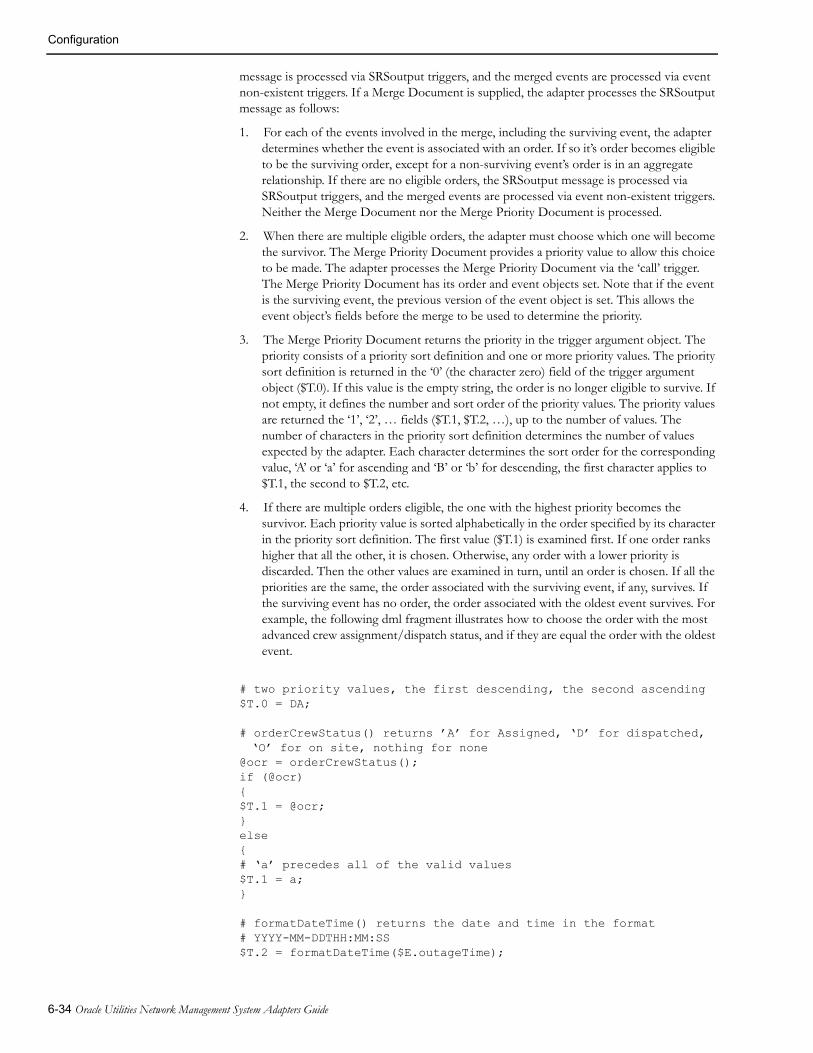
Configuration
message is processed via SRSoutput triggers, and the merged events are processed via event non-existent triggers. If a Merge Document is supplied, the adapter processes the SRSoutput message as follows:
1. For each of the events involved in the merge, including the surviving event, the adapter determines whether the event is associated with an order. If so it’s order becomes eligible to be the surviving order, except for a non-surviving event’s order is in an aggregate relationship. If there are no eligible orders, the SRSoutput message is processed via SRSoutput triggers, and the merged events are processed via event non-existent triggers. Neither the Merge Document nor the Merge Priority Document is processed.
2. When there are multiple eligible orders, the adapter must choose which one will become the survivor. The Merge Priority Document provides a priority value to allow this choice to be made. The adapter processes the Merge Priority Document via the ‘call’ trigger. The Merge Priority Document has its order and event objects set. Note that if the event is the surviving event, the previous version of the event object is set. This allows the event object’s fields before the merge to be used to determine the priority.
3. The Merge Priority Document returns the priority in the trigger argument object. The priority consists of a priority sort definition and one or more priority values. The priority sort definition is returned in the ‘0’ (the character zero) field of the trigger argument object ($T.0). If this value is the empty string, the order is no longer eligible to survive. If not empty, it defines the number and sort order of the priority values. The priority values are returned the ‘1’, ‘2’, … fields ($T.1, $T.2, …), up to the number of values. The number of characters in the priority sort definition determines the number of values expected by the adapter. Each character determines the sort order for the corresponding value, ‘A’ or ‘a’ for ascending and ‘B’ or ‘b’ for descending, the first character applies to $T.1, the second to $T.2, etc.
4. If there are multiple orders eligible, the one with the highest priority becomes the survivor. Each priority value is sorted alphabetically in the order specified by its character in the priority sort definition. The first value ($T.1) is examined first. If one order ranks higher that all the other, it is chosen. Otherwise, any order with a lower priority is discarded. Then the other values are examined in turn, until an order is chosen. If all the priorities are the same, the order associated with the surviving event, if any, survives. If the surviving event has no order, the order associated with the oldest event survives. For example, the following dml fragment illustrates how to choose the order with the most advanced crew assignment/dispatch status, and if they are equal the order with the oldest event.
# two priority values, the first descending, the second ascending $T.0 = DA;
# orderCrewStatus() returns ’A’ for Assigned, ‘D’ for dispatched, ‘O’ for on site, nothing for none
@ocr = orderCrewStatus();if (@ocr){$T.1 = @ocr;}else{# ‘a’ precedes all of the valid values$T.1 = a;}
# formatDateTime() returns the date and time in the format# YYYY-MM-DDTHH:MM:SS$T.2 = formatDateTime($E.outageTime);
6-34 Oracle Utilities Network Management System Adapters Guide

Configuration
5. The Merge Priority Document can populate other fields in the trigger argument object, to be used by the Merge Document when the order being processed becomes the surviving order. Note that the Merge Priority Document is processed even if there is only one eligible order so that these fields, if any, can be passed to the Merge Document.
6. If the surviving order is not associated with the surviving event, the surviving order is re-associated to the surviving event. The order that was associated with the surviving event is re-associated to the surviving order’s old event, so that it can be processed via an event non-existent trigger, to allow normal order clean up.
7. The adapter processes the Merge Document with the surviving order object and surviving event object set to the new version of the event, and the trigger argument object fields set by the Merge Priority Document when processing the surviving order.
8. Finally, the SRSoutput message is processed via SRSoutput triggers, and the merged events are processed via event non-existent triggers.
An example of an event merged trigger is:
TrigEventMerged <EventMerged="OrderMergePriority";>;
For this to be valid, there must be an Output Document named ‘OrderMergePriority’, with a request trigger named ‘call’.
The Root ElementThe root element is the element that contains all of the other elements in an XML document. The root element in dml serves a different purpose depending on whether it is part of an Output or Input Document.
In an Output Document, it is used to generate the root element in the XML to be sent. In an Input Document it is used to select the Input Document or Documents that the input XML can be processed by, similar to a trigger for an Output Document. An example of a root element follows:
&RootElement <environment = $G.environment; revision = "1.0.0";> = CreateJob;
The root element has the same format for both Input and Output Documents.
The root element differs from other elements in that the element’s tag is defined by the value of the element, ‘CreateJob’ in this example. The pseudo-tag ‘RootElement’ keyword identifies it to be the root element.
In an Output Document, the example would generate the following start element tag:
<CreateJob environment="Test" revision="1.0.0">
assuming that the global field ‘environment’ held the value ‘Test’.
To select an Input Document, the input XML’s root element must have the same tag, and all the attributes in the root element specification must be present and have exactly the same contents. Extra attributes in the XML’s root element are ignored.
An Input Document with the same root element definition example above would be selected by the root element in the example above.
The root element is defined in different areas, depending on the type of document.
Generic WebSphere MQ Mobile Adapter 6-35

Configuration
In an Output Document the root element is in the body of the document, because it’s tag may have to be determined during document processing. It is the only element in an Output Document that is an exception to the rule that states that elements are generated in the order that they appear in the Output Document.
In an Input Document the root element is the header of the document because it is used before any processing is done in the document.
The Base PathThe base path only applies to Input Documents, and is not necessary, but can make Input Documents more compact. Consider the following XML:
<ConfirmJob> <ApplicationArea> </ApplicationArea> <DataArea> <Job> <OriginalApplicationArea> <BODId>OrigBODId</BODId> </OriginalApplicationArea> <CreateSuccess> <JobNumber>1234567890</JobNumber> </CreateSuccess> </Job> </DataArea></ConfirmJob>
The XML could contain many other elements, but the ‘BODId’ and ‘JobNumber’ are the only elements to be processed. The elements in the Input Document would be:
&DataArea{
&Job{
&OriginalApplicationArea{&BODId;}&CreateSuccess{&JobNumber;}
}}
Note that ‘BODId’ and ‘JobNumber’ have a common grandparent ‘Job’. By setting the base element to the grandparent by adding:
BasePath = DataArea/Job;
to the document’s header, the elements would become:
&OriginalApplicationArea{
&BODId;}&CreateSuccess{
&JobNumber;}
6-36 Oracle Utilities Network Management System Adapters Guide

Configuration
Stop Statement The Stop statement causes the processing of the current document to stop. It takes the form:
stop;
It is usually contained in an ‘if ’ statement. Any statements with side effects, for example a SQL Insert, processed before the ‘stop’ do take effect.
A stop statement prevents an Output Document’s XML from being sent.
A stop statement in a Configuration Document, described below, causes initialization to fail.
Include StatementSometimes it’s useful to have the same set of statements in two different places in a dml file. For example all Output Documents may need the same header, or application area. This can be achieved by placing the repeated statements in another file and then including the file more than once in another file. The following is an ‘include’ statement:
include ohdr.dml
This ‘include’ statement in effect replaces the text ‘include ohdr.dml’ with the contents of the file ‘ohdr.dml’. Files being included can also include other files, but the nesting level is limited to 10 deep so that infinite recursion can be prevented.
Configuration DocumentsConfiguration Documents are used to set configuration data and load configuration tables from the database at initialization time. They are similar to Input Documents, but have no elements.
They are processed at initialization time, and are then discarded. Any errors encountered when processing a Configuration Document should be made fatal by executing a stop statement, causing initialization to fail.
Common uses are to set fields in the global data object, including configuration fields, and to load mapping tables, used by the ‘mapTableStr’ and ‘mapTableCode’ functions described in DML Function Calls on page 6-70. For example:
ConfigDoc Configure{# fields for other documents$G.OutRequestQueue=NMS.MDS.REQUEST;$G.OutErrorQueue=NMS.ERROR;$G.InReplyQueue=MDS.NMS.REPLY;$G.InRequestQueue=MDS.NMS.REQUEST;$G.environment=Test;
# configuration parameters$G.config_QueueManager_name=OPS;$G.config_OutQueue_req_name=$G.OutRequestQueue;$G.config_OutQueue_err_name=$G.OutErrorQueue;$G.config_OutQueue_numThread=5;$G.config_InQueue_rep_name=$G_InReplyQueue;$G.config_InQueue_rep_numThread=2;$G.config_InQueue_req_name=$G.InRequestQueue;$G.config_InQueue_req_numThread=4;$G.config_ErrorQueue_name=$G.OutErrorQueue;$G.config_ErrorDoc_name=Error;$G.config_ErrorDoc_trigger=xmlErrorTrigger;
$G.config_Relation_Aggregate_AcknowledgeEvents = ack;
Generic WebSphere MQ Mobile Adapter 6-37
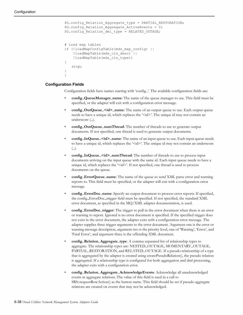
Configuration
$G.config_Relation_Aggregate_type = PARTIAL_RESTORATION;$G.config_Relation_Aggregate_ActiveEvents = Y;$G.config_Relation_dml_type = RELATED_OUTAGE;
# Load map tablesif (!loadMapConfigTable(mds_map_config) || !loadMapTable(mds_cls_desc) || !loadMapTable(mds_cls_type)){
stop;}}
Configuration Fields
Configuration fields have names starting with ‘config_’. The available configuration fields are:
• config_QueueManager_name: The name of the queue manager to use. This field must be specified, or the adapter will exit with a configuration error message.
• config_OutQueue_<id>_name: The name of an output queue to use. Each output queue needs to have a unique id, which replaces the ‘<id>’. The unique id may not contain an underscore (_).
• config_OutQueue_numThread: The number of threads to use to generate output documents. If not specified, one thread is used to generate output documents.
• config_InQueue_<id>_name: The name of an input queue to use. Each input queue needs to have a unique id, which replaces the ‘<id>’. The unique id may not contain an underscore (_).
• config_InQueue_<id>_numThread: The number of threads to use to process input documents arriving on the input queue with the same id. Each input queue needs to have a unique id, which replaces the ‘<id>’. If not specified, one thread is used to process documents on the queue.
• config_ErrorQueue_name: The name of the queue to send XML parse error and warning reports to. This field must be specified, or the adapter will exit with a configuration error message.
• config_ErrorDoc_name: Specify an output document to process error reports. If specified, the config_ErrorDoc_trigger field must be specified. If not specified, the standard XML error document, as specified in the MQ/XML adapter documentation, is used.
• config_ErrorDoc_trigger: The trigger to pull in the error document when there is an error or warning to report. Ignored is no error document is specified. If the specified trigger does not exist in the error document, the adapter exits with a configuration error message. The adapter supplies three trigger arguments to the error document. Argument one is the error or warning message description, argument two is the priority level, one of ‘Warning’, ‘Error’, and ‘Fatal Error’, and argument three is the offending XML document.
• config_Relation_Aggregate_type: A comma separated list of relationship types to aggregate. The relationship types are: NESTED_OUTAGE, MOMENTARY_OUTAGE, PARTIAL_RESTORATION, and RELATED_OUTAGE. If a pseudo relationship of a type that is aggregated by the adapter is created using createPseudoRelation(), the pseudo relation is aggregated. If a relationship type is configured for both aggregation and dml processing, the adapter exits with a configuration error.
• config_Relation_Aggregate_AcknowledgeEvents: Acknowledge all unacknowledged events in aggregate relations. The value of this field is used in a call to SRS::requestRowAction() as the button name. This field should be set if pseudo aggregate relations are created on events that may not be acknowledged.
6-38 Oracle Utilities Network Management System Adapters Guide

Configuration
• config_Relation_Aggregate_ActiveEvents: If the field is not the empty string "", sum count data for all active events in an aggregated relation. The count data event fields are: customersOut, crit_k, crit_c, and crit_d.
• config_Relation_dml_type: A comma separated list of relationship types to be processed by the dml, using the relationship object. The relationship types are: NESTED_OUTAGE, MOMENTARY_OUTAGE, PARTIAL_RESTORATION, and RELATED_OUTAGE. If a pseudo relationship of a type that is processed by the dml is created using createPseudoRelation(), the pseudo relation is processed by the dml. If a relationship type is configured for both aggregation and dml processing, the adapter exits with a configuration error.
• config_Relation_dml_AcknowledgeEvents: Acknowledge all unacknowledged events in dml processed relations. The value of this field is used in a call to SRS::requestRowAction() as the button name.
• config_MaxBackoutCount: The adapter uses the MQSeries syncpoint facilities to preserve input messages when there is a failure. Using the MQSeries syncpoint facilities introduces the possibility that a 'poison' message will be sent by the MDS. A 'poison' message is one that can never be successfully processed, for example because an Oracle Utilities Network Management System table has a constraint that the contents of the message violate. If the 'poison' message is never discarded, MDS will continually try to process the message, fail, and then restart. This parameter sets a limit on the number of restarts that MDS will perform before discarding a message. The default value is five. A value of zero disables this feature. If a message is discarded, the error is logged to the log file, including the offending XML, and if the error document is configured, and an error report is sent to the error queue.
• config_Event_QueueDelay: When event data is received in an SRSoutput message, from SRSService, they are held for this period before they are queued for processing. If another message for the same event is received before the delay has expired, the older message is discarded, and the new message is held for the delay period. This avoids unnecessary processing and message transmission when event data is changing rapidly. Setting this delay too short can cause extra messages, while setting it too long can cause poor response. The value is in seconds. The default value is four seconds. A value of zero disables this feature.
• config_Event_ReprocessPeriod: In certain circumstances, for example when more that one event is grouped, the adapter needs to request an event’s status from SRSService. The adapter periodically requests these events’ statuses in a single request, reducing the burden on SRSService. In addition, if an SRSoutput message for one of these events arrives before it is time to do the request, the request does not have to be made. Setting this period too short can cause extra messages, while setting it too long can cause poor response. The value is in seconds. The default value is six seconds. The minimum value is two seconds. It must be at least 2 seconds longer than config_Event_QueueDelay.
• config_Crew_AssignmentCheckPeriod: When the assignment of crews to events is the responsibility of the adapter, as a proxy for the MDS, Oracle Utilities Network Management System can be configured to reduce the possibility of an operator inadvertently assigning a crew to an event. However, it must be possible to assign crews if Oracle Utilities Network Management System cannot communicate with the MDS, hence mistakes can happen. The adapter periodically checks all crew assignments. A sub-set of crew assignments is checked at the end of each period, the events in ten orders, and ten crews for events not in an order being checked each time. Setting the period too short causes unneeded processing, setting it too long delays such mistakes being repaired. The value is in seconds. The default value is six seconds. A value of zero disables this feature.
• config_Crew_MoveAssignmentCheckDelay: When crew assignments are being checked, allowing the checking to occur during event grouping can, in some configurations, cause unnecessary message traffic between the adapter and SRSService. To prevent this, when a grouping happens, crew assignment checking is delayed. The value is in seconds. The default value is two seconds. A value of zero disables this feature.
Generic WebSphere MQ Mobile Adapter 6-39

Configuration
• config_Relation_CheckPeriod: When event relationships are processed by the adapter, the adapter loads the relationship database table each time a relationship is created, changed or deleted. In addition, the adapter checks for changes to the table at this period. The value is in seconds. The default value is 30 seconds. A value of zero disables this feature.
• config_IgnoreCondStatus: In most implementations of the adapter, additional alarms in the Oracle Utilities Network Management System Work Agenda should not be processed. The value of this configuration parameter is a list of condition statuses, separated by commas (,), that are to be ignored by the adapter. To ignore additional alarms (often NFY events) set this value to 12.
• config_CompleteStatus: In certain situations the adapter need to be able to determine if an event is complete, for example to prevent the assignment of a crew to a completed event, which is illegal. This can only be determined by examining the status string for the event, which is configurable in Oracle Utilities Network Management System. The value of this configuration parameter is a list of statuses, separated by commas (,), that indicate that an event is complete. The default value of this parameter is CMP, CNL.
• config_EventUpdateTimeout: When device outages are confirmed and restored (using confirmDeviceOutage() and restoreOutage()), the new state of the event(s) needs to be read from SRSService. Because device operations are initiated by a message to DDService, which sends a notification to MTService to update the model, which subsequently notifies SRSService of the model change, the new state cannot be read immediately, because SRSService may not have received the notification. To avoid this, the adapter waits for an SRSoutput message updating the event before reading the new state. To prevent the adapter from hanging if an event update does not occur, a timeout is used to interrupt the wait. This value is the timeout in seconds. The default value is 20 seconds. The minimum is two seconds.
• config_MaxThreadBusyUntilFatalError: The adapter monitors the input and output threads to detect Mutex deadlocks, which would cause the adapter to hang. This value is the maximum number of seconds that a thread can be responding to a single trigger or input XML document. The default value is 300 seconds (5 minutes). The minimum is 60 seconds.
• config_StopServiceOnHighLevelStop: The adapter runs as a Windows Service, and it usually set to restart after a period after it fails. (This period is often the minimum one minute). If the adapter tells Windows that it has stopped normally, using a Service Stop message, just before exiting Windows does not try to restart the adapter. If the adapter does not send a Service Stop message, Windows will restart the adapter. When the adapter exits due to Stop request from the Service Property dialog, it sends Windows a Service Stop message, because the user is intending that the adapter stops and does not restart. When the adapter exits abnormally, it does not send a Service Stop message so that Windows will restart the adapter. However, when the adapter is sent a high-level stop message from Oracle Utilities Network Management System using the Action command, the user may or may not want the adapter to restart. This value determines whether the adapter sends a Service Stop message under these circumstances. A value of ‘Y’ causes the adapter to send a Service Stop message, while a value of ‘N’ prevents the adapter from sending a Service Stop message. The default value is ‘N’.
• config_AllowCloseOutEventCancel: When this parameter is set to 'Y,' the DML function closeOutEvent will cancel the event instead of completing it, if the appliedRule value OUTAGE_PND_COMPLETE (26) is passed to the function. When this parameter is set to 'N,' the DML function closeOutEvent will not cancel events. The default value is 'Y'.
• config_IgnoreStormmanUpdates: When this parameter is to set to 'Y' (default), the adapter will not process TRBL_ERT_UPDATE messages generated when Storm Management recalculates ERTs. When this parameter is to set to 'N' the adapter will process such messages.
6-40 Oracle Utilities Network Management System Adapters Guide

Configuration
• config_AllowManualEntryForSCADA: When this parameter is to set to 'Y,' the adapter will perform manual entry in order to operate SCADA device in the NMS model. When this parameter is to set to 'N' (default), the adapter will not be able to operate SCADA devices.
Pseudo RelationshipsPseudo relationships can be created by the dml so that all the events on a single device can be processed in the same way as an Oracle Utilities Network Management System created event relationship. The processing of these relationships is configured in a configuration document.
For example, a probable device outage is created from multiple customer calls grouping to the common transformer, but the crew discovers that there are multiple service problems only affecting some of the customers (perhaps a tree limb took down two service wires). The crew will fix all of the problems, so they do not need multiple MDS orders. When the individual service status is set for the affected customers, all the events generated will be treated in the same way as a partial restoration. (This example assumes that partial restorations are aggregated, and the dml creates a pseudo partial relationship when this situation arises.)
When all of the events in a pseudo relation are completed, the relation itself is automatically completed.
Configuration TablesThe following tables are used in conjunction with the dml files to configure the MDS adapter. They are loaded at startup, or, in some cases, when a dml statement needs them.
The Order TablesThe order tables save order data and configure the fields that are available to the dml in the external Order object, identified by ‘O’ in the dml.
MDS_ORDER
The MDS_ORDER table is used to save order data so that the adapter can continue to process orders over a adapter shutdown restart cycle. While not strictly a configuration table, it is described here to clarify the use of other configuration tables. The table has a fixed set of columns that are always in the table, and columns to hold Order object field values, element values and attribute values. The fixed set of columns is:
Column Type Description
h_cls NUMBER Order class
h_idx NUMBER Order Index
event_cls NUMBER Key event class
event_idx NUMBER Key event index
active_event_cls NUMBER Event class for last active event
active_event_idx NUMBER Event index for last active event
active CHAR(1) Active flag (Y = active, N = inactive)
when_xml_saved DATE When the xml data last sent to the MDS was saved in the database.
when_created DATE When the order was created
when_completed DATE When the order was completed or cancelled
Generic WebSphere MQ Mobile Adapter 6-41

Configuration
The ‘h_cls’ and ‘h_idx’ columns make up the order handle, which identifies the order internally and are the key columns of the table. The order handle is available to the dml with a field name of ‘order’. The ‘event_cls’ and ‘event_idx’ columns make up the handle of the key event for the order. If the event is not aggregated, this is the single event associated with the order. If the event is aggregated, this is the key event of the relationship that makes up the aggregate. The event handle is available to the dml with a field name of ‘event’. The ‘active’ flag indicates whether the order is active, i.e. it has been created, but has neither been completed or cancelled. ‘when_created’ holds the time and date the order was created. ‘when_completed’ holds the time and date the order was completed or cancelled. comp_reason hold the text explaining why the order was completed or cancelled. This text is supplied by the dml when it completes the order by calling the ‘orderComplete’ function.
The columns that hold the field, element and attribute values can have any name, but they must match the contents of the MDS_ORDER_FIELD table and MDS_ORDER_VALUE table. Both are described below. It is suggested that the columns be named similarly to the name of the entity, allowing for the requirements of column names (case insensitivity, etc.). The column types should be VARCHAR2. The columns should be wide enough to hold the data that will be stored in them.
The off-line program that allows dml files to be checked before use can generate suggested contents for the MDS_ORDER, MDS_ORDER_FIELD, and MDS_ORDER_VALUE tables.
MDS_ORDER_FIELD
The MDS_ORDER_FIELD table maps the names of the fields in the Order object to the columns used to save their values in the MDS_ORDER table. In addition, it defines the names of all the fields that are available in the Order object. If the dml references a field that is not in this table, the adapter will log an error and initialization fails. The columns in the table are:
Column Type Description
name VARCHAR2(32) The field’s name.
col VARCHAR2(32) The column in the MDS_ORDER table that holds the field’s value.
comp_reason VARCHAR2(64) Text explaining why the order was completed or cancelled
6-42 Oracle Utilities Network Management System Adapters Guide
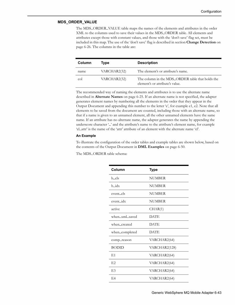
Configuration
MDS_ORDER_VALUE
The MDS_ORDER_VALUE table maps the names of the elements and attributes in the order XML to the columns used to save their values in the MDS_ORDER table. All elements and attributes except those with constant values, and those with the ‘don’t save’ flag set, must be included in this map. The use of the ‘don’t save’ flag is described in section Change Detection on page 6-26. The columns in the table are:
Column Type Description
name VARCHAR2(32) The element’s or attribute’s name.
col VARCHAR2(32) The column in the MDS_ORDER table that holds the element’s or attribute’s value.
The recommended way of naming the elements and attributes is to use the alternate name described in Alternate Names on page 6-25. If an alternate name is not specified, the adapter generates element names by numbering all the elements in the order that they appear in the Output Document and appending this number to the letter ‘e’, for example e1, e2. Note that all elements to be saved from the document are counted, including those with an alternate name, so that if a name is given to an unnamed element, all the other unnamed elements have the same name. If an attribute has no alternate name, the adapter generates the name by appending the underscore character ‘_’ and the attribute’s name to the attribute’s element name, for example ‘el_attr’ is the name of the ‘attr’ attribute of an element with the alternate name ‘el’.
An Example
To illustrate the configuration of the order tables and example tables are shown below, based on the contents of the Output Document in DML Examples on page 6-50.
The MDS_ORDER table schema:
Column Type
h_cls NUMBER
h_idx NUMBER
event_cls NUMBER
event_idx NUMBER
active CHAR(1)
when_xml_saved DATE
when_created DATE
when_completed DATE
comp_reason VARCHAR2(64)
BODID VARCHAR2(128)
E1 VARCHAR2(64)
E2 VARCHAR2(64)
E3 VARCHAR2(64)
E4 VARCHAR2(64)
Generic WebSphere MQ Mobile Adapter 6-43

Configuration
The contents of the MDS_ORDER_FIELD table:
col name
BODID BODId
The contents of the MDS_ORDER_VALUE table (the element tag is not in the table, it is included here to illustrate the numbering of the elements):
E5 VARCHAR2(64)
E6 VARCHAR2(64)
E7 VARCHAR2(64)
E8 VARCHAR2(64)
E9 VARCHAR2(100)
E10 VARCHAR2(64)
E11 VARCHAR2(64)
E12 VARCHAR2(64)
E13 VARCHAR2(64)
E14 VARCHAR2(64)
E15 VARCHAR2(64)
E16 VARCHAR2(100)
E17 VARCHAR2(64)
E18 VARCHAR2(32)
E19 VARCHAR2(32)
col name Element tag
E1 e1 Component
E2 e2 Confirmation
E3 e3 AuthorizationId
E4 e4 CreationDateTime
E5 e5 BODId
E6 e6 ExternalNumber
E7 e7 CreationDateTime
E8 e8 Device
Column Type
6-44 Oracle Utilities Network Management System Adapters Guide

Configuration
The Relationship TablesThe relationship tables save event relationship data and configure the fields that are available to the dml in the external Relationship object, identified by ‘R’ in the dml.
MDS_RELATION
The MDS_RELATION table is used to save relationship data so that the adapter can continue to process event relationships, and to detect changes in these relationships over a adapter shutdown restart cycle. While not strictly a configuration table, it is described here to clarify the use of other configuration tables. The table has a fixed set of columns that are always in the table, and columns to hold Relationship object field values. The fixed set of columns is:
E9 e9 Address
E10 e10 DevPhases
E11 e11 FuseSize
E12 e12 WinterLoad
E13 e13 SummerLoad
E14 e14 NumCustOut
E15 e15 CallerName
E16 e16 CallerAddr
E17 e17 CallerPhone
E18 e18 CallerClues
E19 e19 CallerDevice
col name Element tag
Column Type Description
h_cls NUMBER Relation class
h_idx NUMBER Relation Index
key_event_cls NUMBER Class of key event
key_event_idx NUMBER Index of key event
pseudo_dev_cls NUMBER Class of pseudo device
pseudo_dev_idx NUMBER Index of pseudo device
type NUMBER The type of relationship one of:NESTED_OUTAGE(1) MOMENTARY_OUTAGE(2) PARTIAL_RESTORATION(4) RELATED_OUTAGE(8) Pseudo relationships have the same number as their type, with the sign bit (bit 31) set.
active CHAR(1) Active flag (Y = active, N = inactive)
Generic WebSphere MQ Mobile Adapter 6-45
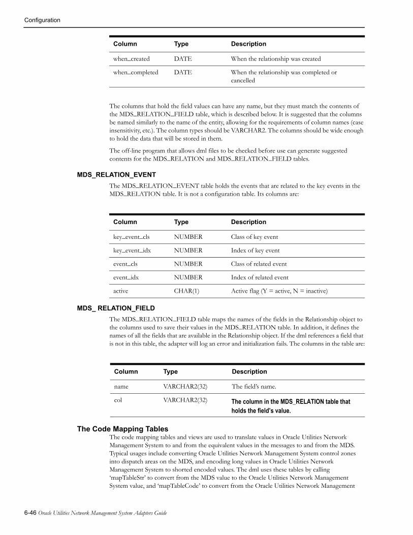
Configuration
The columns that hold the field values can have any name, but they must match the contents of the MDS_RELATION_FIELD table, which is described below. It is suggested that the columns be named similarly to the name of the entity, allowing for the requirements of column names (case insensitivity, etc.). The column types should be VARCHAR2. The columns should be wide enough to hold the data that will be stored in them.
The off-line program that allows dml files to be checked before use can generate suggested contents for the MDS_RELATION and MDS_RELATION_FIELD tables.
MDS_RELATION_EVENT
The MDS_RELATION_EVENT table holds the events that are related to the key events in the MDS_RELATION table. It is not a configuration table. Its columns are:
Column Type Description
key_event_cls NUMBER Class of key event
key_event_idx NUMBER Index of key event
event_cls NUMBER Class of related event
event_idx NUMBER Index of related event
active CHAR(1) Active flag (Y = active, N = inactive)
MDS_ RELATION_FIELD
The MDS_RELATION_FIELD table maps the names of the fields in the Relationship object to the columns used to save their values in the MDS_RELATION table. In addition, it defines the names of all the fields that are available in the Relationship object. If the dml references a field that is not in this table, the adapter will log an error and initialization fails. The columns in the table are:
Column Type Description
name VARCHAR2(32) The field’s name.
col VARCHAR2(32)
The Code Mapping TablesThe code mapping tables and views are used to translate values in Oracle Utilities Network Management System to and from the equivalent values in the messages to and from the MDS. Typical usages include converting Oracle Utilities Network Management System control zones into dispatch areas on the MDS, and encoding long values in Oracle Utilities Network Management System to shorted encoded values. The dml uses these tables by calling ‘mapTableStr’ to convert from the MDS value to the Oracle Utilities Network Management System value, and ‘mapTableCode’ to convert from the Oracle Utilities Network Management
when_created DATE When the relationship was created
when_completed DATE When the relationship was completed or cancelled
Column Type Description
The column in the MDS_RELATION table that holds the field’s value.
6-46 Oracle Utilities Network Management System Adapters Guide

Configuration
System value to the MDS value. A table can be loaded using the function ‘loadMapTable’. All these functions take the name of the table as a parameter.
The tables and views have the following columns:
Column Type Description
string VARCHAR2 The value in Oracle Utilities Network Management System.
code VARCHAR2 The equivalent value in message.
The width of the columns can be any appropriate value.
There are three types of mapping table:
• Those that map from string to code. In these cases the strings must be unique in the table.
• Those that map from code to string. In these cases the code must be unique in the table.
• Those that map both ways. In these cases the strings and codes must be unique.
This can be configured in a map configuration table, described below. If these is no configuration for the table, and informational message is output to the log, and the table is assumed to map both ways.
It is sometimes convenient to add a code column to other Oracle Utilities Network Management System tables to avoid redundant data. Data from these tables can be accessed by use of a view that maps the appropriate column names to ‘string’ and ‘code’.
If a value to be translated is not present in the table, a default value is used. If the default is not specified, the empty string is used.
The types of the tables and their defaults are specified in a map configuration table, which has the following columns:
Column Type Description
tablename VARCHAR2 The name of the table the default applies to.
type CHAR(1) The type of the table. ‘C’ maps from string to code, ‘S’ maps from code to string, and ‘B’ maps both ways.
string VARCHAR2 The default Oracle Utilities Network Management System value.
code VARCHAR2 The default message value.
The width of the columns can be any appropriate value. A map configuration table is loaded using a function call similar to ‘loadMapConfigTable(mds_map_config)’. The configuration document is a convenient place to do this. There can be multiple map configuration tables loaded.
The SRS Message Type TableThe SRS Message Type Table, MDS_SRS_MSG_TYPE, configures the processing of SRSoutput InterSys messages. It has the following columns:
Column Type Description
message_type NUMBER The SRSoutput message type that this row configures
action CHAR(1) How to process it. ‘I’, ‘D’, ‘P’ or ‘R’.
Generic WebSphere MQ Mobile Adapter 6-47

Configuration
The message_type column values are the SRSoutput message types listed in SRSoutput.h.
The action column must be one of these values:
• ‘I’: completely ignore this message type. Any message type not included in the table is ignored.
• ‘D’: do not process the message, but apply the proc_relation and special flags if they are set.
• ‘P’: process the message as is, after applying the flags.
• ‘R’: reprocess the message’s event after applying the flags. Some SRSoutput messages do not hold all of the event’s data (e.g., DAMAGE_RPT_UPDATE), and some are used to update the viewer when conditions are to be hidden and may or may not indicate that an event has changed state (e.g., TRBL_REMOVE_ALL). As a consequence, these messages do not hold all the data required to process them. In these cases, the adapter requests SRSService to send all the current data for the message’s event.
When set to a value of ‘Y’, the proc_relation flag instructs the adapter to apply special relation processing to the message. This processing is activated when the appliedRule field of the SRSoutput message contains one of the following values: OUTAGE_PART_REST, OUTAGE_RELATED or OUTAGE_UNRELATED. These indicate that the event is part of a relationship that has been created, deleted or modified. In these cases, the adapter loads the current state of all relationships, reacts to the changes, and reprocesses the message’s event after a delay to allow any upcoming changes to the event to arrive before rereading the event’s data.
When set to a value of ‘Y’, the special flag instructs the adapter to apply special, message type specific, processing to the message. The following message types have special processing available:
• TRBL_CLEAR: If the applied rule is not OUTAGE_MERGED, the event is processed by all Output Documents with a ‘EventNonexistent trigger.
In addition to the processing of the special flag described above, the following message types are processed differently from normal SRSoutput messages because they are not formatted in the normal manner:
• TRBL_ERT_UPDATE: This message contains a list of estimated time of restoration updates. If this message type is not completely ignored, all the events in the message are reprocessed. As this message contains the events’ indexes, but not the events’ classes, the potential classes need to be supplied in the event_cls1 and event_cls2 columns. One or both of the classes (normal and momentary event classes) can be configured. If one is zero, it is ignored.
• TRBL_WCB_UPDATE: This message type is not implemented in the adapter. If this message is not configured to be completely ignored, the adapter issues a warning to the log each time this message type is received.
The High Priority Category TableThe High Priority Category Table, MDS_HIGH_PRI_CAT, configures the priorities used by the functions ‘highPriTCCategoriesFromClues’. It has the following columns:
proc_relation CHAR(1) Should special relationship processing be applied to it? ‘Y’ or ‘N’.
special CHAR(1) Should special processing be applied to it? ‘Y’ or ‘N’.
event_cls1 NUMBER Event class for TRBL_ERT_UPDATE
event_cls2 NUMBER Event class for TRBL_ERT_UPDATE
Column Type Description
6-48 Oracle Utilities Network Management System Adapters Guide
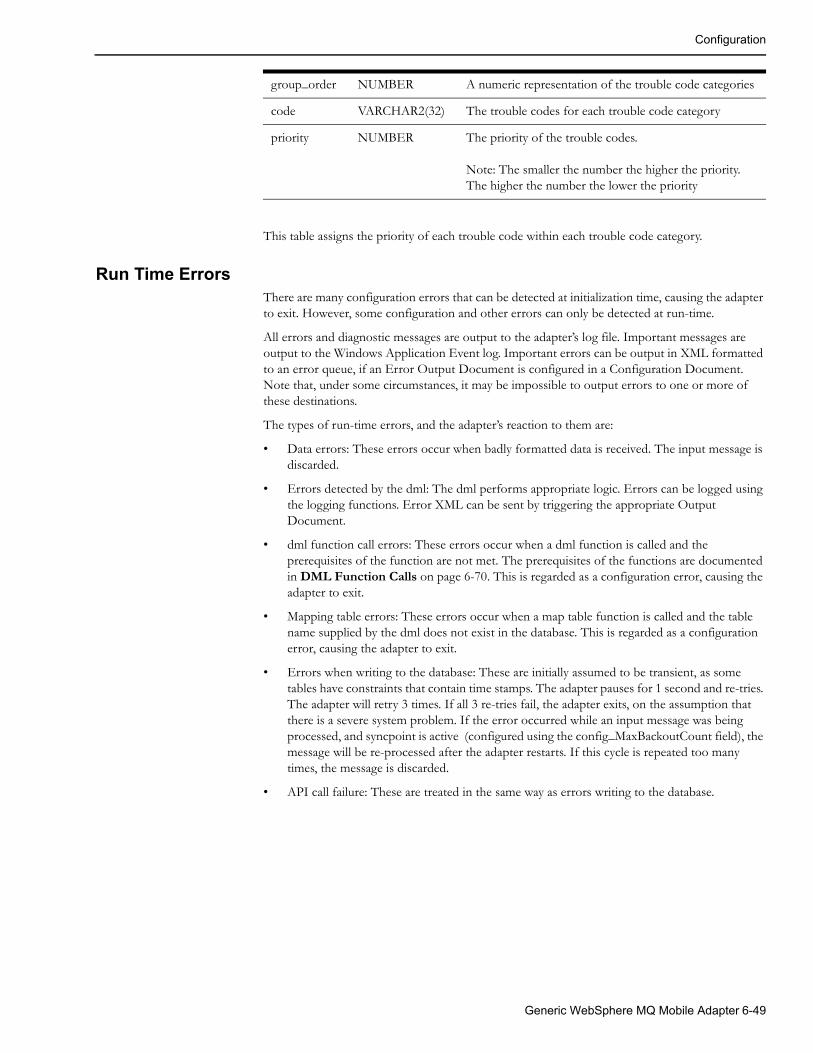
Configuration
This table assigns the priority of each trouble code within each trouble code category.
Run Time ErrorsThere are many configuration errors that can be detected at initialization time, causing the adapter to exit. However, some configuration and other errors can only be detected at run-time.
All errors and diagnostic messages are output to the adapter’s log file. Important messages are output to the Windows Application Event log. Important errors can be output in XML formatted to an error queue, if an Error Output Document is configured in a Configuration Document. Note that, under some circumstances, it may be impossible to output errors to one or more of these destinations.
The types of run-time errors, and the adapter’s reaction to them are:
• Data errors: These errors occur when badly formatted data is received. The input message is discarded.
• Errors detected by the dml: The dml performs appropriate logic. Errors can be logged using the logging functions. Error XML can be sent by triggering the appropriate Output Document.
• dml function call errors: These errors occur when a dml function is called and the prerequisites of the function are not met. The prerequisites of the functions are documented in DML Function Calls on page 6-70. This is regarded as a configuration error, causing the adapter to exit.
• Mapping table errors: These errors occur when a map table function is called and the table name supplied by the dml does not exist in the database. This is regarded as a configuration error, causing the adapter to exit.
• Errors when writing to the database: These are initially assumed to be transient, as some tables have constraints that contain time stamps. The adapter pauses for 1 second and re-tries. The adapter will retry 3 times. If all 3 re-tries fail, the adapter exits, on the assumption that there is a severe system problem. If the error occurred while an input message was being processed, and syncpoint is active (configured using the config_MaxBackoutCount field), the message will be re-processed after the adapter restarts. If this cycle is repeated too many times, the message is discarded.
• API call failure: These are treated in the same way as errors writing to the database.
group_order NUMBER A numeric representation of the trouble code categories
code VARCHAR2(32) The trouble codes for each trouble code category
priority NUMBER The priority of the trouble codes.
Note: The smaller the number the higher the priority. The higher the number the lower the priority
Generic WebSphere MQ Mobile Adapter 6-49

Configuration
DML Examples
An Output DocumentThe following is an example of an Output Document that generates a create request document for a small MDS order. Various lines are numbered to allow reference to them in the explanation below. The numbers are not part of the syntax.
1 OutputDoc Job2 queue=$G.OutRequestQueue; associate=O; persist="Y";3 triggerCreate< SRSoutput; > = isIn($E.status, "ACK", "ASN", "ENR", "RST") &&
($E.outageHdl.cls != $G.momentary) &&!findOrder(event, $E.outageHdl);
4 triggerUpdate:S < SRSoutput; > = findOrder(event, $E.outageHdl) && (!isIn($E.status, "UNA", "CNL"));
5 {6 @docType = ChangeJob;7 if (triggerCreate)8 {9 @docType = CreateJob;10 createOrder();11 }12 &RootElement<environment = $G.environment; revision = "1.0.0";> = @docType;13 &ApplicationArea14 {15 &Sender16 {17 &Component = NMS;18 &Confirmation = "Always";19 &AuthorizationId = "NMS Interface";20 }21 &CreationDateTime = formatDTNow();22 @BODId = getGuid();23 &BODId = @BODId;24 }25 &DataArea26 {27 &ExternalNumber = "NMS:"+ $E.outageHdl.idx;28 # CreationDateTime is outageTime which is 29 # either when the first customer called30 # or when the device was opened in the model31 &CreationDateTime=formatDateTime($E.outageTime);32 &Device:S = $E.devAlias;33 &Address:S = substring($E.dispAddress, 0, 100);34 sqlselect @devPhases, @fuseSize, @winter_load, @summer_load |
phase_designation, fuse_size, kva_lod_win, kva_lod_sumr |classTable($E.devHdl.cls) | "where h_idx = " | $E.devHdl.idx;
35 &DevPhases = @devPhases;36 &FuseSize = @fuseSize;37 &WinterLoad = @winter_load;38 &SummerLoad = @summer_load;39 &NumCustOut:S = $E.customersOut;40 &CallerName = $I.0.getCustomerName;41 &CallerAddr = $I.0.getAddrStreet + “ “ + $I.0.getAddrCity;42 &CallerPhone = $I.0.getCustomerPhone;43 &CallerClues = $I.0.getShortDesc;44 &CallerDevice = $I.0.getDeviceAlias;45 }46 $O.BODId = @BODId;47 }
6-50 Oracle Utilities Network Management System Adapters Guide
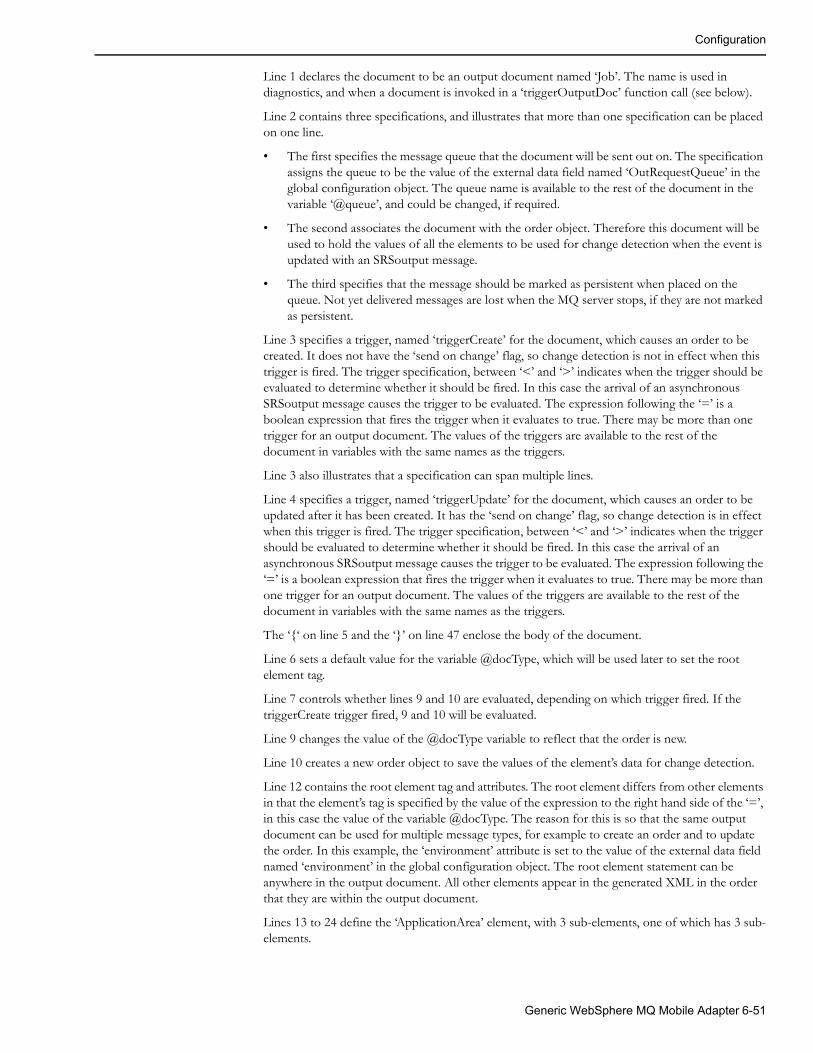
Configuration
Line 1 declares the document to be an output document named ‘Job’. The name is used in diagnostics, and when a document is invoked in a ‘triggerOutputDoc’ function call (see below).
Line 2 contains three specifications, and illustrates that more than one specification can be placed on one line.
• The first specifies the message queue that the document will be sent out on. The specification assigns the queue to be the value of the external data field named ‘OutRequestQueue’ in the global configuration object. The queue name is available to the rest of the document in the variable ‘@queue’, and could be changed, if required.
• The second associates the document with the order object. Therefore this document will be used to hold the values of all the elements to be used for change detection when the event is updated with an SRSoutput message.
• The third specifies that the message should be marked as persistent when placed on the queue. Not yet delivered messages are lost when the MQ server stops, if they are not marked as persistent.
Line 3 specifies a trigger, named ‘triggerCreate’ for the document, which causes an order to be created. It does not have the ‘send on change’ flag, so change detection is not in effect when this trigger is fired. The trigger specification, between ‘<’ and ‘>’ indicates when the trigger should be evaluated to determine whether it should be fired. In this case the arrival of an asynchronous SRSoutput message causes the trigger to be evaluated. The expression following the ‘=’ is a boolean expression that fires the trigger when it evaluates to true. There may be more than one trigger for an output document. The values of the triggers are available to the rest of the document in variables with the same names as the triggers.
Line 3 also illustrates that a specification can span multiple lines.
Line 4 specifies a trigger, named ‘triggerUpdate’ for the document, which causes an order to be updated after it has been created. It has the ‘send on change’ flag, so change detection is in effect when this trigger is fired. The trigger specification, between ‘<’ and ‘>’ indicates when the trigger should be evaluated to determine whether it should be fired. In this case the arrival of an asynchronous SRSoutput message causes the trigger to be evaluated. The expression following the ‘=’ is a boolean expression that fires the trigger when it evaluates to true. There may be more than one trigger for an output document. The values of the triggers are available to the rest of the document in variables with the same names as the triggers.
The ‘{‘ on line 5 and the ‘}’ on line 47 enclose the body of the document.
Line 6 sets a default value for the variable @docType, which will be used later to set the root element tag.
Line 7 controls whether lines 9 and 10 are evaluated, depending on which trigger fired. If the triggerCreate trigger fired, 9 and 10 will be evaluated.
Line 9 changes the value of the @docType variable to reflect that the order is new.
Line 10 creates a new order object to save the values of the element’s data for change detection.
Line 12 contains the root element tag and attributes. The root element differs from other elements in that the element’s tag is specified by the value of the expression to the right hand side of the ‘=’, in this case the value of the variable @docType. The reason for this is so that the same output document can be used for multiple message types, for example to create an order and to update the order. In this example, the ‘environment’ attribute is set to the value of the external data field named ‘environment’ in the global configuration object. The root element statement can be anywhere in the output document. All other elements appear in the generated XML in the order that they are within the output document.
Lines 13 to 24 define the ‘ApplicationArea’ element, with 3 sub-elements, one of which has 3 sub-elements.
Generic WebSphere MQ Mobile Adapter 6-51
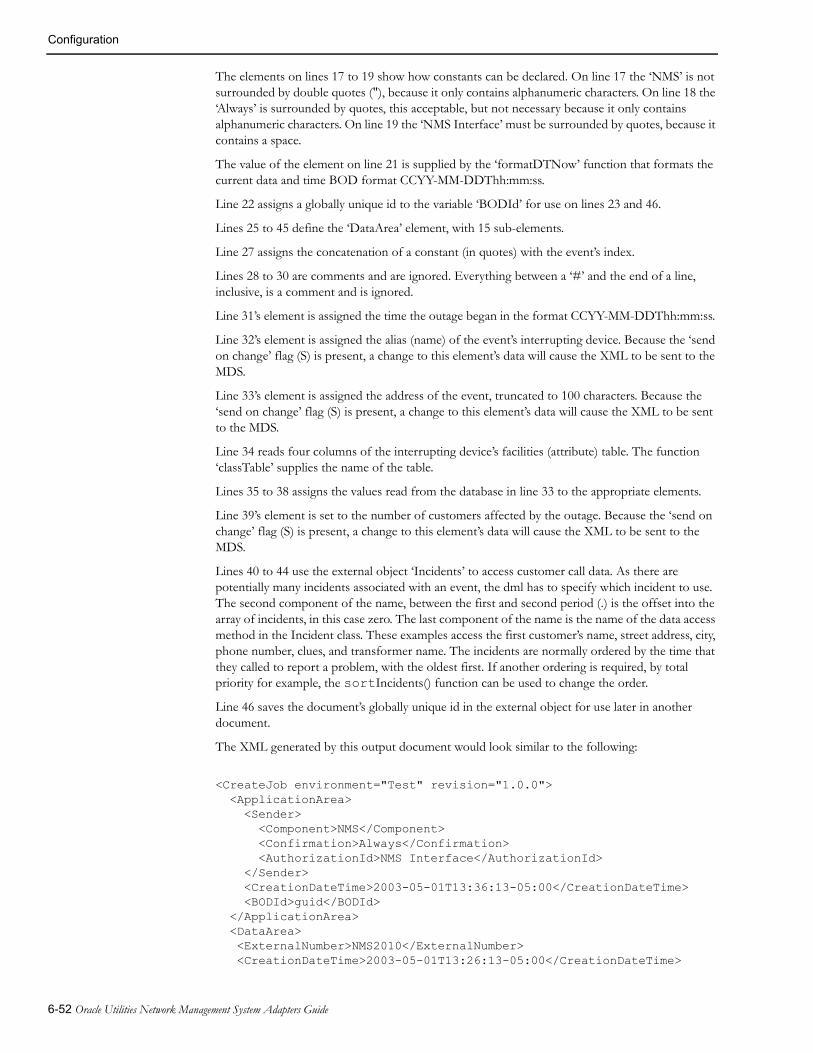
Configuration
The elements on lines 17 to 19 show how constants can be declared. On line 17 the ‘NMS’ is not surrounded by double quotes ("), because it only contains alphanumeric characters. On line 18 the ‘Always’ is surrounded by quotes, this acceptable, but not necessary because it only contains alphanumeric characters. On line 19 the ‘NMS Interface’ must be surrounded by quotes, because it contains a space.
The value of the element on line 21 is supplied by the ‘formatDTNow’ function that formats the current data and time BOD format CCYY-MM-DDThh:mm:ss.
Line 22 assigns a globally unique id to the variable ‘BODId’ for use on lines 23 and 46.
Lines 25 to 45 define the ‘DataArea’ element, with 15 sub-elements.
Line 27 assigns the concatenation of a constant (in quotes) with the event’s index.
Lines 28 to 30 are comments and are ignored. Everything between a ‘#’ and the end of a line, inclusive, is a comment and is ignored.
Line 31’s element is assigned the time the outage began in the format CCYY-MM-DDThh:mm:ss.
Line 32’s element is assigned the alias (name) of the event’s interrupting device. Because the ‘send on change’ flag (S) is present, a change to this element’s data will cause the XML to be sent to the MDS.
Line 33’s element is assigned the address of the event, truncated to 100 characters. Because the ‘send on change’ flag (S) is present, a change to this element’s data will cause the XML to be sent to the MDS.
Line 34 reads four columns of the interrupting device’s facilities (attribute) table. The function ‘classTable’ supplies the name of the table.
Lines 35 to 38 assigns the values read from the database in line 33 to the appropriate elements.
Line 39’s element is set to the number of customers affected by the outage. Because the ‘send on change’ flag (S) is present, a change to this element’s data will cause the XML to be sent to the MDS.
Lines 40 to 44 use the external object ‘Incidents’ to access customer call data. As there are potentially many incidents associated with an event, the dml has to specify which incident to use. The second component of the name, between the first and second period (.) is the offset into the array of incidents, in this case zero. The last component of the name is the name of the data access method in the Incident class. These examples access the first customer’s name, street address, city, phone number, clues, and transformer name. The incidents are normally ordered by the time that they called to report a problem, with the oldest first. If another ordering is required, by total priority for example, the sortIncidents() function can be used to change the order.
Line 46 saves the document’s globally unique id in the external object for use later in another document.
The XML generated by this output document would look similar to the following:
<CreateJob environment="Test" revision="1.0.0"> <ApplicationArea> <Sender> <Component>NMS</Component> <Confirmation>Always</Confirmation> <AuthorizationId>NMS Interface</AuthorizationId> </Sender> <CreationDateTime>2003-05-01T13:36:13-05:00</CreationDateTime> <BODId>guid</BODId> </ApplicationArea> <DataArea> <ExternalNumber>NMS2010</ExternalNumber> <CreationDateTime>2003-05-01T13:26:13-05:00</CreationDateTime>
6-52 Oracle Utilities Network Management System Adapters Guide

Configuration
<Device>XFM12345678</Device> <Address>5800 Yonge St. North York</Address> <DevPhases>A</DevPhases> <FuseSize>100</FuseSize> <WinterLoad>40</WinterLoad> <SummerLoad>45</SummerLoad> <NumCustOut>4</NumCustOut> <CallerName>M.J. McLaughlin</CallerName> <CallerAddr>5802 Yonge St. North York</CallerAddr> <CallerPhone>416 555-1212</CallerPhone> <CallerClues>NC</CallerClues> <CallerDevice>XFM12345678</CallerDevice> </DataArea></CreateJob>
An Input DocumentThe following is an example of an Input Document that processes a document containing completion data for an order. Various lines are numbered to allow reference to them in the explanation below. The numbers are not part of the syntax.
1 InputDoc CompletionData2 queue=$G.InRequestQueue;3 &RootElement<environment=$G.environment; revision="1.0.0";> =4 FieldReportSave;5 BasePath=DataArea;6 {7 &JobNumber:R;8 &Crew9 {10 &CrewKey11 {12 &CrewName::"MDS";13 }14 }15 &CompletionData16 {17 &System:R;18 &Type:R;19 &Failure:R;20 &Cause:R;21 &InterruptDev:R;22 &Action:R;23 &OtherAction::Other;24 &RestoredTime;25 &CustomerCaseNotes:::CCN;26 }2728 if (!findOrder(externalId, &JobNumber))29 {30 stop;31 }3233 @action=(&CompletionData/Action == "Other")
? &CompletionData/OtherAction: &CompletionData/Action;
34 @restoredTime = decodeDateTime(&CompletionData/RestoredTime);35 sqlupdate picklist_info_upd_tr |
system_om, type_om,failure_om, cause_om,interrupt_dev_om, action_text,
Generic WebSphere MQ Mobile Adapter 6-53

Configuration
crew_restore |&CompletionData/System, &CompletionData/Type,&CompletionData/Failure, &CompletionData/Cause,&CompletionData/InterruptDev, @action,@restoredTime |ref_id | $O.event.idx;
36 # call SRS::setCaseNoteInfo if appropriate37 if (isSet(&CCN))38 {39 setCaseNoteInfo(getCaseNotesForEvent($O.event) + " " + &CCN);40 }41 # set no dtr flag if appropriate42 if (isIn(&CompletionData/Type, "Customer Trouble",43 "Other Utilities", 44 "Scheduled/Customer Notified"))45 {46 sqlupdate picklist_info_upd_tr | no_dtr_flag | Y |
ref_id | $O.event.idx;47 }
# log change to event48 @reason_for_update="Completion Information for Job " +
&JobNumber + " from MDS";49 sqlinsert picklist_completion_log |
ref_id, who,reason_for_update, when |
$O.event.idx, &Crew/CrewKey/CrewName, @reason_for_update, time();5051 }
Line 1 declares the document to be an input document named ‘CompletionData’.
Line 2 specifies the message queue that the document will be received on. The statement assigns the queue to be the value of the external data field named ‘InRequestQueue’ in the global configuration object.
Line 3 contains the root element tag and attributes. The root element differs from other elements in that the element’s tag is specified by the value of the expression to the right hand side of the ‘=’, in this case ‘FieldReportSave’. The ‘environment’ attribute is set to the value of the external data field named ‘environment’ in the global configuration object. In contrast with output documents, the root element statement is in the header of the input document.
A message arriving on the message queue with the name specified on line 2, and with a root element tag and attributes as specified on line 3, triggers the processing of the message by the input document.
Line 5 specifies the base element’s tag. The base element specifies the sub-element of the root element at which to start processing the elements specified in the body of the input document. The base element is optional, but is convenient in that it reduces the element nesting level in the body of the input document.
The ‘{‘ on line 6 and the ‘}’ on line 51 enclose the body of the document.
Lines 7 to 26 define the tags for the elements that will be processed by the input document.
Line 7 defines a required element ‘JobNumber’. The ‘R’ in the flags field of the element definition indicates that the element must be present in the input XML for the document to be processed. All required elements must be present, otherwise the XML will be ignored.
6-54 Oracle Utilities Network Management System Adapters Guide

Configuration
Line 12 defines an optional element ‘CrewName’, a sub-element of ‘CrewKey’, which is in turn a sub-element of ‘Crew’. The element has a default value of ‘MDS’, which is the value used by references to the element in the rest of the document, when the element is not present. If a default value is not present, missing elements have a value of the empty string.
Lines 15 to 26 define the ‘CompletionData’ element, which has 9 sub-elements, some of which are required.
If all the required elements are present, the data can be processed.
Line 28 calls the ‘findOrder’ function that finds the order object with an ‘externalId’ field equal to the JobNumber supplied in the XML. This function returns a boolean indicating whether such an order object was found, or not. This result is inverted by the ‘!’ so that line 30 is executed if ‘findOrder’ fails. Line 30 is a stop statement, which causes the processing of the document to terminate.
Line 33 sets the variable ‘action’ to either the contents of the ‘OtherAction’ element or the ‘Action’ element, depending on whether ‘Action’ has a value of ‘Other’ or not. Both these elements are sub-elements of the ‘CompletionData’ element. A reference to a sub-element takes the form ‘&grandparent/parent/subelement’.
Alternatively, an element can be named to make the references more succinct. The element definition of ‘CustomerCareNotes’ with a name of ‘CCN” on line 25, and the references to it on lines 37 and 39 are an example of this.
Line 34 converts the time in the element ‘RestoredTime’ into a format suitable to be passed to the database, and saves it in the variable ‘restoredTime’.
Line 35 saves the values of 5 elements and 2 variables in the ‘picklist_info_upd_tr’ table in the database using a sqlupdate statement. This table has a key column ‘ref_id’ that is set to the order’s event’s index number. If aggregate processing has been configured, and the intention is to save the data in the database for all events in the aggregation, the function ‘picklistInfoUpdTr’ would be more appropriate.
Line 37 tests whether the element named ‘CCN’ (the ‘CustomerCaseNotes’ element in ‘CompletionData’), was present in the input XML, using the function ‘isSet’. If the element was set line 39 is executed . The function call to ‘getCaseNotesForEvent’ in the parameter list of the call to ‘setCaseNoteInfo’, calls an Oracle Utilities Network Management System API to read the current value of the order’s event case notes. The value returned is concatenated with a space and the value of the CCN element. The resulting value is saved to the event’s case notes using the function ‘setCaseNoteInfo’.
Lines 42 to 47 set the ‘no_dtr_flag’ column in the ‘picklist_info_upd_tr’ table to ‘Y’, if the ‘CompletionData/Type’ element indicates that the trouble was not with the utility’s equipment. The function ‘isIn’ returns true if its first parameter matches any one of the rest of its parameters, false otherwise
Lines 48 and 49 logs the change to the event by inserting a row into the picklist_completion_log table. If aggregate processing has been configured, and the intention is to save the data in the database for all events in the aggregation, the function ‘picklistCompLog’ would be more appropriate.
The following XML would be processed by the example input document
<FieldReportSave environment="Test" revision="1.0.0"> <ApplicationArea> <Sender> <Component>MDS</Component> <Confirmation>Never</Confirmation> <AuthorizationId>MDS Interface</AuthorizationId> </Sender> <CreationDateTime>2003-05-01T14:30:17-05:00</CreationDateTime> <BODId>guid</BODId>
Generic WebSphere MQ Mobile Adapter 6-55

DML Reference
</ApplicationArea> <DataArea> <JobNumber>MDS7704</JobNumber> <CompletionData> <System>4KV</System> <Type>Lateral</Type> <Failure>Fuse</Failure> <Cause>Animal</Cause> <InterruptDev>XFM12345678</InterruptDev> <Action>Fuse replaced</Action> <CustomerCaseNotes>Temporary Repair: Scheduled for Tuesday</CustomerCaseNotes> </CompletionData> </DataArea></FieldReportSave>
DML ReferenceThis section contains a full reference for the dynamic message language used in the Generic WebSphere MQ Mobile Adapter configuration dml files.
Lexical ConventionsA dml configuration consists of one or more files. Each file is processed in turn to generate a sequence of tokens, which are further processed into internal data structures used at run time to generate XML documents and process XML documents.
Syntax notationIn the syntax notation used in this Appendix, syntactic categories are indicated by italic type, and literal words and characters in bold type. An optional part of the syntax is indicated by enclosing it in square brackets ([]). An ellipsis (…) indicates that the preceding part of the syntax can be optionally repeated an arbitrary number of times.
TokensThere are seven kinds of tokens: names, strings, quoted strings, keywords, operators, and other separators. Blanks, tabs, line feeds, carriage returns, and comments (described below), are ignored except as they serve to separate tokens. Some white space is required to separate otherwise adjacent tokens.
CommentsThe character # starts a comment which terminates at the end of the line on which it occurs.
Include DirectiveThe include directive can appear anywhere in an input file and takes the form:
include file name
The contents of the file name are processed as if they replaced the include directive itself.
KeywordsThe following names are reserved for use as keywords and may not be used otherwise:
6-56 Oracle Utilities Network Management System Adapters Guide
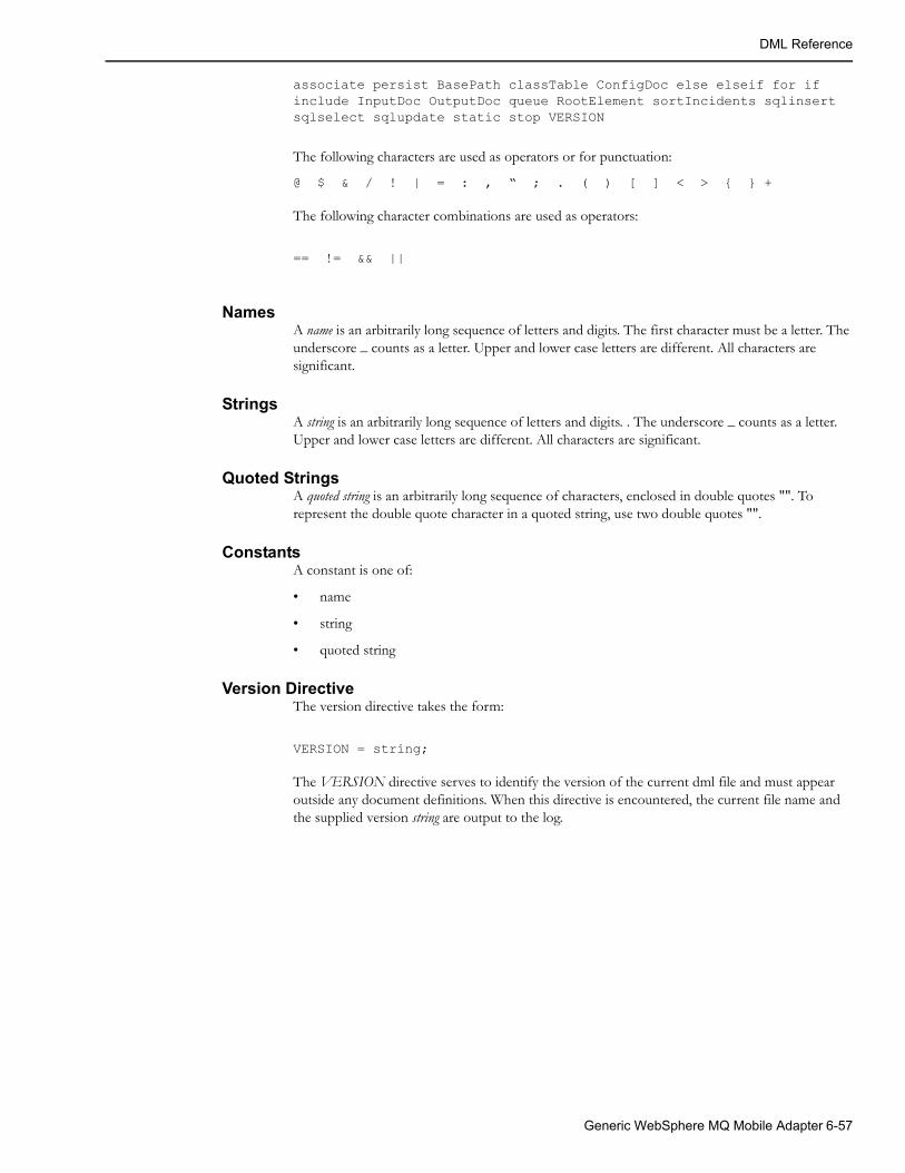
DML Reference
associate persist BasePath classTable ConfigDoc else elseif for if include InputDoc OutputDoc queue RootElement sortIncidents sqlinsert sqlselect sqlupdate static stop VERSION
The following characters are used as operators or for punctuation:
@ $ & / ! | = : , “ ; . ( ) [ ] < > { } +
The following character combinations are used as operators:
== != && ||
NamesA name is an arbitrarily long sequence of letters and digits. The first character must be a letter. The underscore _ counts as a letter. Upper and lower case letters are different. All characters are significant.
StringsA string is an arbitrarily long sequence of letters and digits. . The underscore _ counts as a letter. Upper and lower case letters are different. All characters are significant.
Quoted StringsA quoted string is an arbitrarily long sequence of characters, enclosed in double quotes "". To represent the double quote character in a quoted string, use two double quotes "".
ConstantsA constant is one of:
• name
• string
• quoted string
Version DirectiveThe version directive takes the form:
VERSION = string;
The VERSION directive serves to identify the version of the current dml file and must appear outside any document definitions. When this directive is encountered, the current file name and the supplied version string are output to the log.
Generic WebSphere MQ Mobile Adapter 6-57

DML Reference
Basic Concepts
Type(s)DML is a typeless language, or perhaps more accurately, a singly typed language. All values consist of character strings. DML has no concept of numbers. To illustrate this, strings can be used to pass positive integers to functions. For example:
@truncatedString = substring(@address, 0, 100);
However, quoted strings must be used to pass negative integers. For example:
@lastCharacter = substring(@characters, "-1", 1);
It should be emphasized that it is the function, not the dml that is interpreting the character string as an integer.
In certain contexts, a value is used as a boolean, or logical, value. Any non-empty string is considered true, and the empty string (written as "") is considered false. A boolean expression or function returns "Y" when true and "" when false.
Definitions and ReferencesThere are a number of value bearing entities in dml. Apart from one exception (variables), they must be defined before they are referenced. The definition introduces the entity, and defines certain modifiers to the entity. An entity is referenced when its value is used in an expression or when it is assigned to in an assignment statement. When a variable uses the default set of modifiers, it can be implicitly defined when first assigned.
Entities
The entities in a document carry values and have modifiers that change their behavior.
Variables
A variable is used to save intermediate results in a document. A variable definition takes the form:
@name:modifiers
The name must be unique amongst the variables within the document. Other entities can have the same name. The :modifiers is optional.
If the :modifiers are not required, variables can be implicitly defined when they are assigned to.
A variable reference takes the form:
@name
Variables can be set and referenced in all document types.
ElementsAn element generates an XML element in Output Documents, and supplies an input XML element value or sub-elements in Input Documents. There are to kinds of element definitions: plain elements and array elements.
plain element definitions and an array element definitions are known collectively as element definitions.
6-58 Oracle Utilities Network Management System Adapters Guide
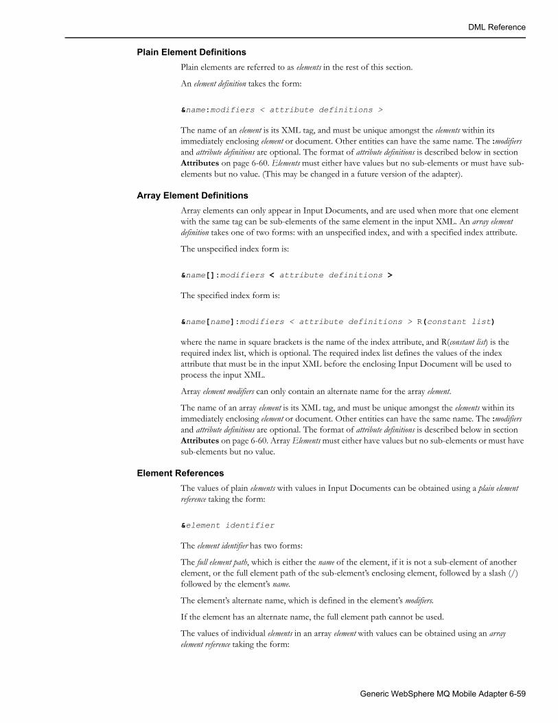
DML Reference
Plain Element Definitions
Plain elements are referred to as elements in the rest of this section.
An element definition takes the form:
&name:modifiers < attribute definitions >
The name of an element is its XML tag, and must be unique amongst the elements within its immediately enclosing element or document. Other entities can have the same name. The :modifiers and attribute definitions are optional. The format of attribute definitions is described below in section Attributes on page 6-60. Elements must either have values but no sub-elements or must have sub-elements but no value. (This may be changed in a future version of the adapter).
Array Element Definitions
Array elements can only appear in Input Documents, and are used when more that one element with the same tag can be sub-elements of the same element in the input XML. An array element definition takes one of two forms: with an unspecified index, and with a specified index attribute.
The unspecified index form is:
&name[]:modifiers < attribute definitions >
The specified index form is:
&name[name]:modifiers < attribute definitions > R(constant list)
where the name in square brackets is the name of the index attribute, and R(constant list) is the required index list, which is optional. The required index list defines the values of the index attribute that must be in the input XML before the enclosing Input Document will be used to process the input XML.
Array element modifiers can only contain an alternate name for the array element.
The name of an array element is its XML tag, and must be unique amongst the elements within its immediately enclosing element or document. Other entities can have the same name. The :modifiers and attribute definitions are optional. The format of attribute definitions is described below in section Attributes on page 6-60. Array Elements must either have values but no sub-elements or must have sub-elements but no value.
Element References
The values of plain elements with values in Input Documents can be obtained using a plain element reference taking the form:
&element identifier
The element identifier has two forms:
The full element path, which is either the name of the element, if it is not a sub-element of another element, or the full element path of the sub-element’s enclosing element, followed by a slash (/) followed by the element’s name.
The element’s alternate name, which is defined in the element’s modifiers.
If the element has an alternate name, the full element path cannot be used.
The values of individual elements in an array element with values can be obtained using an array element reference taking the form:
Generic WebSphere MQ Mobile Adapter 6-59
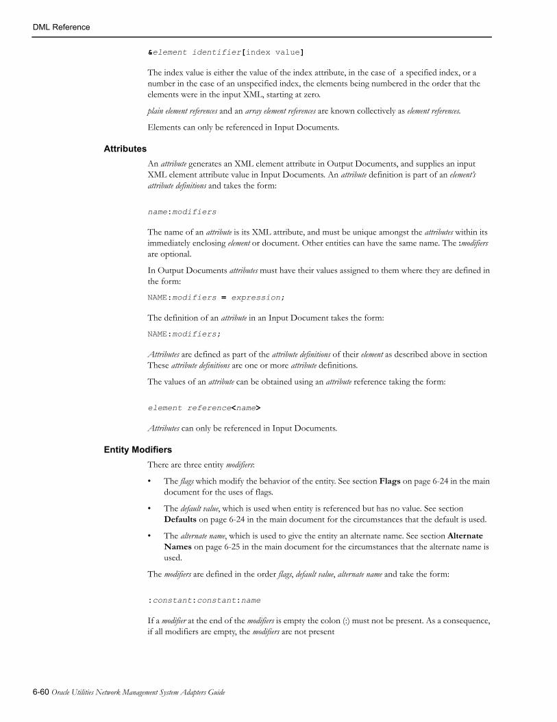
DML Reference
&element identifier[index value]
The index value is either the value of the index attribute, in the case of a specified index, or a number in the case of an unspecified index, the elements being numbered in the order that the elements were in the input XML, starting at zero.
plain element references and an array element references are known collectively as element references.
Elements can only be referenced in Input Documents.
Attributes
An attribute generates an XML element attribute in Output Documents, and supplies an input XML element attribute value in Input Documents. An attribute definition is part of an element’s attribute definitions and takes the form:
name:modifiers
The name of an attribute is its XML attribute, and must be unique amongst the attributes within its immediately enclosing element or document. Other entities can have the same name. The :modifiers are optional.
In Output Documents attributes must have their values assigned to them where they are defined in the form:
NAME:modifiers = expression;
The definition of an attribute in an Input Document takes the form:
NAME:modifiers;
Attributes are defined as part of the attribute definitions of their element as described above in section These attribute definitions are one or more attribute definitions.
The values of an attribute can be obtained using an attribute reference taking the form:
element reference<name>
Attributes can only be referenced in Input Documents.
Entity Modifiers
There are three entity modifiers:
• The flags which modify the behavior of the entity. See section Flags on page 6-24 in the main document for the uses of flags.
• The default value, which is used when entity is referenced but has no value. See section Defaults on page 6-24 in the main document for the circumstances that the default is used.
• The alternate name, which is used to give the entity an alternate name. See section Alternate Names on page 6-25 in the main document for the circumstances that the alternate name is used.
The modifiers are defined in the order flags, default value, alternate name and take the form:
:constant:constant:name
If a modifier at the end of the modifiers is empty the colon (:) must not be present. As a consequence, if all modifiers are empty, the modifiers are not present
6-60 Oracle Utilities Network Management System Adapters Guide

DML Reference
External DataExternal data is available from the various external data objects, described above in section The External Objects on page 6-28. All fields in the objects can be read, but some objects or individual fields are read-only, i.e. they cannot be written.
A reference to an external object field takes the form:
$external data object identifier.field name
where the external data object identifier is the letter associated with the object and the field name is the name of the field (note that they are separated by a period (.)). Some fields (for example Handles) have sub-fields. A reference to a sub-field takes the form:
$external data object identifier.field name.sub-field name
Most external objects have one instance at a time, but the Incident Object can have zero, one or more, depending on the number of incidents that have grouped to the current event. To reference an individual incident field, an offset to the incident into the array of incidents is required. This offset starts at zero, and is a constant which must only contain digits, known as an offset. The normal order of incidents is the order that they were received by Oracle Utilities Network Management System. This order can be altered by use of the sortIncidents function. A reference to an incident field takes the form:
$I.offset.field name
Incident references can contain sub-fields.These are known as external field references.
Note that some external object fields are read-only, i.e., they cannot be set by the dml. The read-only status of each external object is listed below:
• The Order Object (‘O’): All the fields listed in section Permanent Order Object Fields on page 6-135, Permanent Order Object Fields on page 6-135 of DML Function Calls on page 6-70 are read-only. All other fields are read/write.
• The Relationship Object (‘R’): All the fields listed in section Permanent Relationship Object Fields on page 6-135, Permanent Relationship Object Fields on page 6-135 of DML Function Calls on page 6-70 are read-only. All other fields are read/write.
• The Event Object (‘E’): All fields are read-only.
• The Incident Object(‘I’): All fields are read-only.
• The Global Data Object (‘G’): All fields are read/write.
• The Trigger Parameter Object (‘T’): All fields are read/write.
FunctionsA function is called using the following form:
name([parameter1] [, parameter2] …)
Where name is the name of the function and parameter2, parameter2, … are expressions. All functions return a value, but in some cases the value is always the empty string, implying that they are only called for their side effects. The functions available and their parameters are described in DML Function Calls on page 6-70.
Generic WebSphere MQ Mobile Adapter 6-61
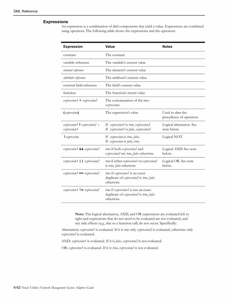
DML Reference
ExpressionsAn expression is a combination of dml components that yield a value. Expressions are combined using operators. The following table shows the expressions and the operators:
Expression Value Notes
constant The constant
variable reference The variable’s current value
element reference The element’s current value
attribute reference The attribute’s current value
external field reference The field’s current value
function The function’s return value
expression1 + expression2 The concatenation of the two expressions
(expression) The expression’s value Used to alter the precedence of operators.
expression1 ? expression2 : expression3
If expression1 is true, expression2.If expression1 is false, expression3.
Logical alternation. See note below.
!expression If expression is true, false.If expression is false, true.
Logical NOT.
expression1 && expression2 true if both expression1 and expression2 are true, false otherwise
Logical AND. See note below.
expression1 || expression2 true if either expression1 or expression2 is true, false otherwise
Logical OR. See note below.
expression1 == expression2 true if expression1 is an exact duplicate of expression2 is true, false otherwise
expression1 != expression2 true if expression1 is not an exact duplicate of expression2 is true, false otherwise
Note: The logical alternation, AND, and OR expressions are evaluated left to right and expressions that do not need to be evaluated are not evaluated, and any side effects (e.g., due to a function call) do not occur. Specifically:
Alternation: expression1 is evaluated. If it is true only expression2 is evaluated, otherwise only expression3 is evaluated.
AND: expression1 is evaluated. If it is false, expression2 is not evaluated.
OR: expression1 is evaluated. If it is true, expression2 is not evaluated.
6-62 Oracle Utilities Network Management System Adapters Guide

DML Reference
Lists
Name List
A name list is one or more names separated by commas (,). For example:
h_cls, h_idx
Constant List
A constant list is one or more constants, separated by commas (,). For example:
None, "$%I99", 13, "-3", "This is a ""quoted"" string"
Variable Reference Lists
A variable reference list is one or more variable references, separated by commas (,). For example:
@devPhases, @pole_number, @winter_load, @summer_load
Expression List
A expression list is one or more expressions, separated by commas (,). For example:
@a + @b, formatDateTime(@time), $E.outageHdl.idx, none
StatementsStatements are the basic processing units in dml. Many of them are terminated using the statement terminator, ; (semi-colon).
Statement Blocks
A number of statements require one or more statements grouped together. This is achieved using a statement block, which takes the form:
{statements
}
Where statements is one or more statements.
Variable Assignment Statement
This statement assigns a value to a variable and takes the form:
variable reference = expression;
Element Definition Statement
Element definitions differ between elements with values (simple elements) and those with sub-elements (compound elements). They also differ between those in Output Documents (output elements) and those in Input Documents (input elements). The four flavors are described in the following sections.
Output Element Definition Statements
These statements are only valid in Output Documents.
Simple Output Element Definition Statement
This statement assigns a value to an element and takes the form:
element definition = expression;
Generic WebSphere MQ Mobile Adapter 6-63
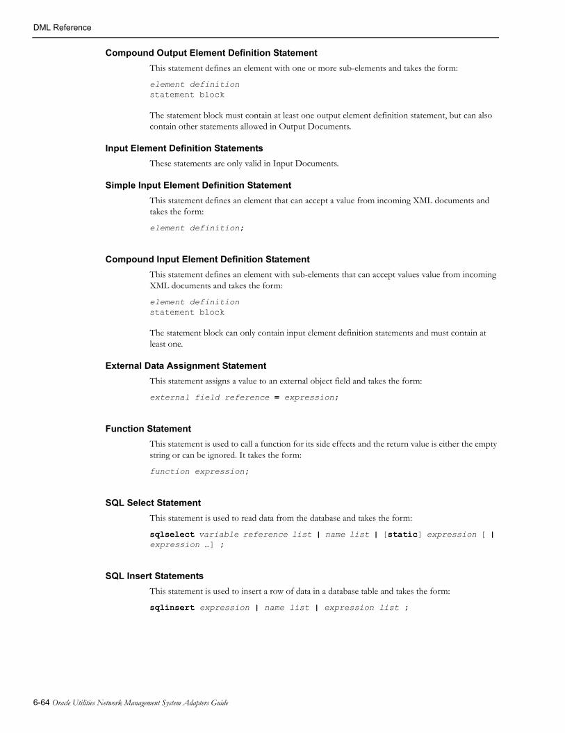
DML Reference
Compound Output Element Definition Statement
This statement defines an element with one or more sub-elements and takes the form:
element definitionstatement block
The statement block must contain at least one output element definition statement, but can also contain other statements allowed in Output Documents.
Input Element Definition Statements
These statements are only valid in Input Documents.
Simple Input Element Definition Statement
This statement defines an element that can accept a value from incoming XML documents and takes the form:
element definition;
Compound Input Element Definition Statement
This statement defines an element with sub-elements that can accept values value from incoming XML documents and takes the form:
element definitionstatement block
The statement block can only contain input element definition statements and must contain at least one.
External Data Assignment Statement
This statement assigns a value to an external object field and takes the form:
external field reference = expression;
Function Statement
This statement is used to call a function for its side effects and the return value is either the empty string or can be ignored. It takes the form:
function expression;
SQL Select Statement
This statement is used to read data from the database and takes the form:
sqlselect variable reference list | name list | [static] expression [ | expression …] ;
SQL Insert Statements
This statement is used to insert a row of data in a database table and takes the form:
sqlinsert expression | name list | expression list ;
6-64 Oracle Utilities Network Management System Adapters Guide
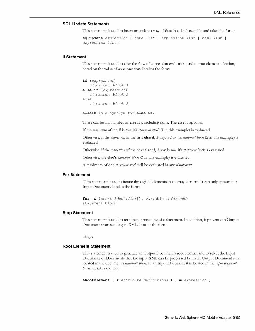
DML Reference
SQL Update Statements
This statement is used to insert or update a row of data in a database table and takes the form:
sqlupdate expression | name list | expression list | name list | expression list ;
If Statement
This statement is used to alter the flow of expression evaluation, and output element selection, based on the value of an expression. It takes the form:
if (expression)statement block 1
else if (expression)statement block 2
elsestatement block 3
elseif is a synonym for else if.
There can be any number of else if ’s, including none. The else is optional.
If the expression of the if is true, it’s statement block (1 in this example) is evaluated.
Otherwise, if the expression of the first else if, if any, is true, it’s statement block (2 in this example) is evaluated.
Otherwise, if the expression of the next else if, if any, is true, it’s statement block is evaluated.
Otherwise, the else’s statement block (3 in this example) is evaluated.
A maximum of one statement block will be evaluated in any if statement.
For Statement
This statement is use to iterate through all elements in an array element. It can only appear in an Input Document. It takes the form:
for (&element identifier[], variable reference)statement block
Stop Statement
This statement is used to terminate processing of a document. In addition, it prevents an Output Document from sending its XML. It takes the form:
stop;
Root Element Statement
This statement is used to generate an Output Document’s root element and to select the Input Document or Documents that the input XML can be processed by. In an Output Document it is located in the document’s statement block. In an Input Document it is located in the input document header. It takes the form:
&RootElement [ < attribute definitions > ] = expression ;
Generic WebSphere MQ Mobile Adapter 6-65
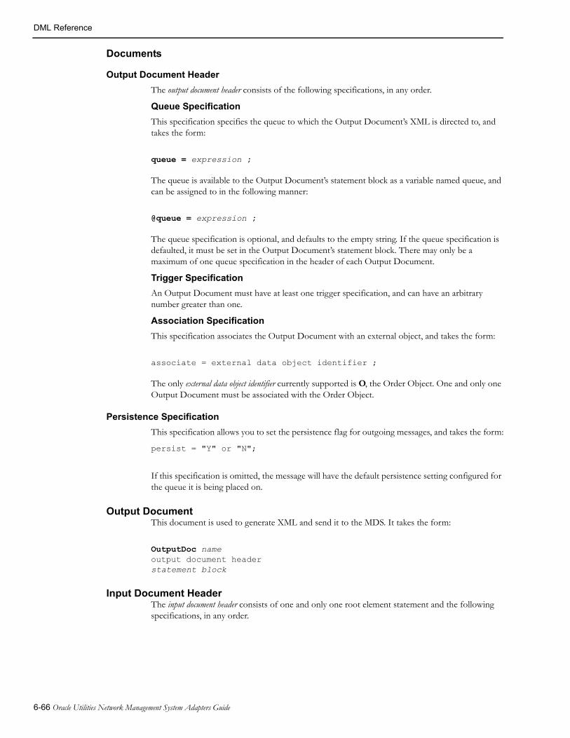
DML Reference
Documents
Output Document Header
The output document header consists of the following specifications, in any order.
Queue Specification
This specification specifies the queue to which the Output Document’s XML is directed to, and takes the form:
queue = expression ;
The queue is available to the Output Document’s statement block as a variable named queue, and can be assigned to in the following manner:
@queue = expression ;
The queue specification is optional, and defaults to the empty string. If the queue specification is defaulted, it must be set in the Output Document’s statement block. There may only be a maximum of one queue specification in the header of each Output Document.
Trigger Specification
An Output Document must have at least one trigger specification, and can have an arbitrary number greater than one.
Association Specification
This specification associates the Output Document with an external object, and takes the form:
associate = external data object identifier ;
The only external data object identifier currently supported is O, the Order Object. One and only one Output Document must be associated with the Order Object.
Persistence Specification
This specification allows you to set the persistence flag for outgoing messages, and takes the form:
persist = "Y" or "N";
If this specification is omitted, the message will have the default persistence setting configured for the queue it is being placed on.
Output DocumentThis document is used to generate XML and send it to the MDS. It takes the form:
OutputDoc nameoutput document headerstatement block
Input Document HeaderThe input document header consists of one and only one root element statement and the following specifications, in any order.
6-66 Oracle Utilities Network Management System Adapters Guide

DML Reference
Queue Specification
This specification specifies the queue on which the Input Document’s XML is received from, and takes the form:
queue = expression ;
The queue is available to the Input Document’s statement block as a variable named queue.
There must be one and only one queue specification in the header of each Input Document.
Base Path Specification
The specification specifies the sub-element of the root element of the XML document which contains all elements that will be processed by the Input Document. It takes the form:
BasePath = full element path;
Input Document
This document is used to process input XML from the MDS. It takes the form:
InputDoc nameinput document headerstatement block
Configuration DocumentThis document is used to set configuration data and load configuration tables from the database at initialization time. It takes the form:
ConfigDoc namestatement block
Order of Document Processing and Other ConsiderationsThe dml is read during adapter initialization in the order that the files are specified in the command line. Files from the command line must contain only complete documents, but files read using the include directive can contain any valid dml fragment, dependent on the context of the directive.
The processing of statements within a document is strictly from top to bottom in the order the statements were read during initialization, except when altered by a control flow statement (e.g., if and for statements). Statements in a document are processed until one of the following situations occur:
The last statement in the document is reached. If the document is an Output Document, the resulting XML is delivered to the queue specified in the document’s queue specification.
A stop statement is processed. If the document is a Configuration Document, the adapter sends an error message to the log and then exits.
A run time configuration error occurs. In all cases, the adapter sends an error message to the log and then exits.
An unrecoverable run time error occurs (e.g., DBService is not available to read or write a database table). In all cases, the adapter sends an error message to the log and then exits.
The processing of specifications in a document header is not necessarily in top to bottom order. Each document is described below.
Generic WebSphere MQ Mobile Adapter 6-67

DML Reference
Output DocumentsOutput Document specifications are processed in the following order:
The association specification is processed once during initialization.
The queue specification is evaluated just before the first statement of the document is processed.
When a trigger event occurs, all Output Documents are examined in top to bottom order to determine whether the event should trigger each document.
If the trigger event’s type matches at least one trigger specification in the document, the triggers of that type are processed in top to bottom order, until one evaluates to true. In this case, all other triggers have their value set to false, even if they have not been processed. If all triggers evaluate to false the document is not processed due to the trigger event.
If the Output Document is triggered, it is fully processed before the next Output Document is examined in order to determine whether the event should trigger the next document.
Input DocumentsAll Input Document header specifications are evaluated at initialization, in the order base path specification, queue specification, and then root element specification.
When an input XML document arrives, each Input Document is examined in top to bottom order to determine whether the XML satisfies the root element specification. If no document matches the incoming XML, the XML is discarded. If at least one Input Document is eligible, the elements in the XML are delivered to the documents in the order they appear in the XML document. Once all elements have been delivered, each document is examined in top to bottom order to determine whether all required elements are present, and are processed in top to bottom order if the elements are present. Once all Input Documents have been processed, the XML is discarded.
Configuration DocumentsConfiguration Documents have no header specifications. All Configuration Documents are processed in top to bottom order. Once they all have been processed successfully, they are discarded.
Ordering of Incidents in the Incident ObjectWhen processing starts for a document, the incidents in the Incident Object are in their normal order, i.e. the order that they were received by Oracle Utilities Network Management System. This order can be changed during the processing of the document by calling the sortIncidents function. The ordering remains the same during the processing, unless sortIncidents is called again. The order is set back to normal when the document processing finishes.
Interactions between ThreadsThe adapter is a multi-threaded process. Therefore more than one document can be processed at the same time, increasing performance. There is at least one thread for Output Document processing, and at least one thread for each Input Document queue. More threads can be configured using a Configuration Document. The adapter uses a number of other threads for internal processing.
This has a number of implications.
While trigger events are queued internally in the order that they occur, and are extracted from this queue in the order that they were queued, there is no guarantee that the Output Documents triggered by these events will complete their processing in the order the events were queued. This means the XML messages may be delivered to the MQSeries queue in an unexpected order. If this behavior is inappropriate, it can be eliminated at the expense of performance by using only one output thread, and by setting the config_Event_QueueDelay configuration parameter to zero.
A similar situation exists with input XML documents. They also cannot be guaranteed to update Oracle Utilities Network Management System in the order that they arrive. This situation can be
6-68 Oracle Utilities Network Management System Adapters Guide

DML Reference
improved at the expense of performance by limiting each input queue to one thread. It may be possible to eliminate it completely if the interface can be configured to use only one input queue.
Note that trigger events and input XML that affect particular Oracle Utilities Network Management System events, Order Objects, and Relationship Objects are processed in the order that they are queued. These situations are discussed below.
Note, however, that there is an inherent race condition in loosely coupled interfaces (the type implemented by the adapter) that use messages to communicate. Events can occur in Oracle Utilities Network Management System and the MDS that alter the state of Oracle Utilities Network Management System events and MDS orders almost simultaneously and it cannot be predicted whether the change on one system affects the other system first, or vice versa. Paradoxically, this situation can be improved by increasing the rate at which messages are processed, i.e. by increasing the number of threads.
The input, output, and internal threads need to coordinate access to various shared resources. Most of this coordination is invisible on the dml level, but a number of aspects of the coordination are worth consideration when writing dml.
One specific means of coordination is known as a mutex (for mutual exclusion). To access a shared resource that is protected by a mutex, the thread requests the mutex. If the mutex is free, the thread acquires the mutex. If another thread requests the mutex, it blocks (is suspended) until it is free. When the original thread has finished accessing the shared resource, it releases the mutex, making it free. The release unblocks one thread waiting for the mutex. When there is the potential for more than one mutex to be in use, there is a danger of a deadlock if one thread enters the mutexes in a different order from another thread. One a deadlock occurs, neither thread will ever run again.
Each thread runs in a separate environment, with a copy of each relevant document, but needs to share a number of resources. The access to these objects must be properly coordinated to prevent inconsistent access due to multiple threads updating the resource at the same time. These resources and the mechanisms used to prevent inconsistent access are:
• The Global Data Object: The update of a single field is atomic (the update will be complete before any other thread can attempt to read or update the field). There is no coordination of updates to multiple fields. To avoid this problem, use a single field.
• The Order Object: There is one Order Object for each order that has been created. Access to an individual Order Object is coordinated so that only one document can access the Order Object at one time. When a document in a thread needs to access an Order Object it calls findOrder. When successful, findOrder acquires the order’s mutex, preventing any other thread from accessing the Order Object. The order’s mutex is automatically acquired when the order is created by calling createOrder. The order’s mutex is automatically released in the following cases: when the document processing is terminated, and when findOrder or createOrder is called. This is to prevent deadlocks. A consequence of this is that if a trigger event triggers two Output Documents needing the same order, or two Input Documents are triggered by one input XML message, the state of the order when the second document starts processing is not guaranteed to be the same, because another thread may have altered its state.
• The Relationship Object: There is one Relationship Object for each relationship that has been created. Access to an individual Relationship Object is coordinated so that only one document can access the Relationship Object at one time. When a document in a thread needs to access a Relationship Object it calls findRelation. When successful, findRelation acquires the relationship’s mutex, preventing any other thread from accessing the Relationship Object. The relationship’s mutex is automatically acquired when the relationship is created by calling createRelation. The relationship’s mutex is automatically released in the following cases: when the document processing is terminated, and when findRelation or createRelation is called. This is to prevent deadlocks. A consequence of this is that if a trigger event triggers two Output Documents using needing the same relationship, or two Input Documents are triggered by one input XML message, the state of the relationship when the second document starts processing is not guaranteed to be the same, because another thread
Generic WebSphere MQ Mobile Adapter 6-69
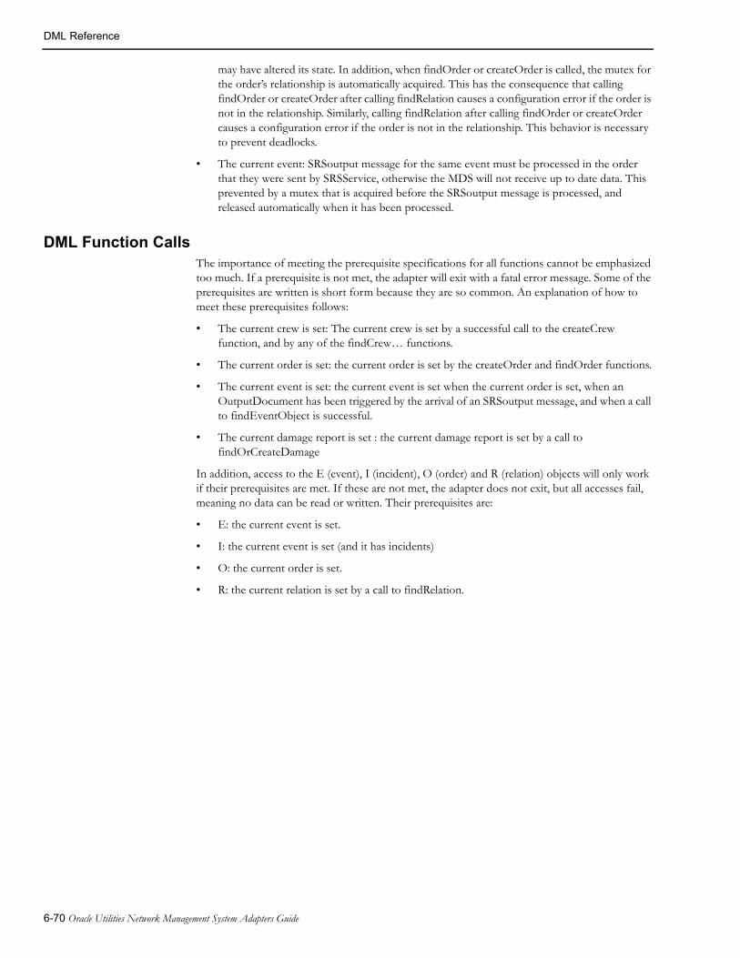
DML Reference
may have altered its state. In addition, when findOrder or createOrder is called, the mutex for the order’s relationship is automatically acquired. This has the consequence that calling findOrder or createOrder after calling findRelation causes a configuration error if the order is not in the relationship. Similarly, calling findRelation after calling findOrder or createOrder causes a configuration error if the order is not in the relationship. This behavior is necessary to prevent deadlocks.
• The current event: SRSoutput message for the same event must be processed in the order that they were sent by SRSService, otherwise the MDS will not receive up to date data. This prevented by a mutex that is acquired before the SRSoutput message is processed, and released automatically when it has been processed.
DML Function CallsThe importance of meeting the prerequisite specifications for all functions cannot be emphasized too much. If a prerequisite is not met, the adapter will exit with a fatal error message. Some of the prerequisites are written is short form because they are so common. An explanation of how to meet these prerequisites follows:
• The current crew is set: The current crew is set by a successful call to the createCrew function, and by any of the findCrew… functions.
• The current order is set: the current order is set by the createOrder and findOrder functions.
• The current event is set: the current event is set when the current order is set, when an OutputDocument has been triggered by the arrival of an SRSoutput message, and when a call to findEventObject is successful.
• The current damage report is set : the current damage report is set by a call to findOrCreateDamage
In addition, access to the E (event), I (incident), O (order) and R (relation) objects will only work if their prerequisites are met. If these are not met, the adapter does not exit, but all accesses fail, meaning no data can be read or written. Their prerequisites are:
• E: the current event is set.
• I: the current event is set (and it has incidents)
• O: the current order is set.
• R: the current relation is set by a call to findRelation.
6-70 Oracle Utilities Network Management System Adapters Guide

DML Reference
List of Functions
Crew FunctionsThese functions create and update crews.
createCrew
NAME:
createCrew Create a new crew.
SYNOPSIS:
createCrew( crew ID, crew field, data, [crew field, data], ..)
PARAMETERS:
crew IDThe crew ID
crew fieldThe crew field to update.
crewType calls Crew::crewType() API
zoneName calls Crew::zoneName() API
crewSize calls Crew::crewSize() API
contact calls Crew::contact() API
crewId calls Crew::crewId() API
mobileNum calls Crew::mobileNum() API
pagerNum calls Crew::pagerNum() API
zoneHdl calls Crew::zoneHdl() API
crewCategory calls Crew::crewCategory() API
crewCenter calls Crew::crewCenter() API
crewGroup calls Crew::crewGroup() API
crewSupervisor calls Crew::crewSupervisor() API
externalKey calls Crew::externalKey() API
data The data written to the crew field
Note: If the Crew Icons Window is used make sure that the following crew fields: crewType, contact, zoneName, zoneHdl, crewCategory, crewCenter, crewSupervisor, are included otherwise the new crew will not appear in the Window.PRE-REQUISITE:
The crew field parameters are valid.
DESCRIPTION:
Create a new crew with the specified information using the Crew::createCrew API. If successful, set the current crew to the new crew.
RETURN VALUE:
True when successful.
False when unsuccessful.
A crew with the specified crew ID exists. This can be determined by a call to findCrewById().
The Crew::createCrew() API call fails.
Generic WebSphere MQ Mobile Adapter 6-71

DML Reference
Note that the current crew is not set if the call fails.
DIAGNOSTICS:
Error messages are output to the error log.
findCrewById
NAME:
findCrewById Find an active or inactive crew based on its crew ID SYNOPSIS:
findCrewById( crew ID )
crew ID The crew ID.
PRE-REQUISITE:
None.
DESCRIPTION:
Find the crew with the specified crew ID.
RETURN VALUE:
True when successful. The current crew is set to the crew that was found.
False when unsuccessful.DIAGNOSTICS:
None.
findCrewByExternalKey
NAME:
findCrewByExternalKey Find an active or inactive crew based on its external key
SYNOPSIS:
findCrewByExternalKey( externalKey )
externalKey The external key.
PRE-REQUISITE:
None.
DESCRIPTION:
Find the crew with the specified external key.
RETURN VALUE:
True, when successful. The current crew is set to the crew that was found.
False when unsuccessful.
DIAGNOSTICS:
Error messages are output to the error log.
6-72 Oracle Utilities Network Management System Adapters Guide
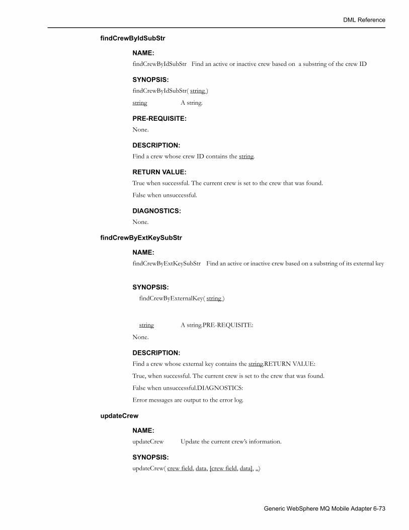
DML Reference
findCrewByIdSubStr
NAME:
findCrewByIdSubStr Find an active or inactive crew based on a substring of the crew ID
SYNOPSIS:
findCrewByIdSubStr( string )
string A string.
PRE-REQUISITE:
None.
DESCRIPTION:
Find a crew whose crew ID contains the string.
RETURN VALUE:
True when successful. The current crew is set to the crew that was found.
False when unsuccessful.
DIAGNOSTICS:
None.
findCrewByExtKeySubStr
NAME:
findCrewByExtKeySubStr Find an active or inactive crew based on a substring of its external key
SYNOPSIS:
findCrewByExternalKey( string )
string A string.PRE-REQUISITE:
None.
DESCRIPTION:
Find a crew whose external key contains the string.RETURN VALUE:
True, when successful. The current crew is set to the crew that was found.
False when unsuccessful.DIAGNOSTICS:
Error messages are output to the error log.
updateCrew
NAME:
updateCrew Update the current crew’s information.
SYNOPSIS:
updateCrew( crew field, data, [crew field, data], ..)
Generic WebSphere MQ Mobile Adapter 6-73

DML Reference
PARAMETERS:
crew field The crew’s field to update.
crewType calls Crew::crewType() API
zoneName calls Crew::zoneName() API
crewSize calls Crew::crewSize() API
contact calls Crew::contact() API
crewId calls Crew::crewId() API
mobileNum calls Crew::mobileNum() API
pagerNum calls Crew::pagerNum() API
zoneHdl calls Crew::zoneHdl() API
crewCategory calls Crew::crewCategory() API
crewCenter calls Crew::crewCenter() API
crewGroup calls Crew::crewGroup() API
crewSupervisor calls Crew::crewSupervisor() API
externalKey calls Crew::externalKey() API
data The data written to the crew field
PRE-REQUISITE:
The current crew is set.
The crew field parameters are valid.
DESCRIPTION:
Update the current crew’s crew field with data and invoke the Crew::commit() API to commit the changes.
RETURN VALUE:
True when successful.
False when unsuccessful.
The Crew::commit() API call fails.
DIAGNOSTICS:
Error messages are output to the error log.
dispatchCrew
NAME:
dispatchCrew Dispatch the current crew to the current order
SYNOPSIS:
dispatchCrew()
PARAMETERS:
None.
6-74 Oracle Utilities Network Management System Adapters Guide

DML Reference
PRE-REQUISITE:
The current crew is set.
The current order is set.
DESCRIPTION:
If the crew is already dispatched to another event, the previous dispatch is changed to an assignment.
Invoke the Crew::dispatch() API for the order’s active event. If the order is aggregated, assign the crew to the other events.
RETURN VALUE:
The empty string.
DIAGNOSTICS:
Error messages are output to the error log.
arriveCrew
NAME:
arriveCrew Update the current crew’s information to reflect that the crew has arrived on site for an order.
SYNOPSIS:
arriveCrew()
arriveCrew(time)
PARAMETERS:
time The time the crew arrived in internal format. If this parameter is notsupplied, the current time is used.
PRE-REQUISITE:
The current crew is set.
The current order is set.
DESCRIPTION:
If the crew is not dispatched to the order, the crew is dispatched to the order, using the logic described in the description of the ‘dispatchCrew’ function.
If the time is zero or invalid it is set to the current time
Invoke the CrewDispatch::arrived() API for the order’s active event.
RETURN VALUE:
The empty string.DIAGNOSTICS:
Error messages are output to the error log.
Generic WebSphere MQ Mobile Adapter 6-75

DML Reference
assignCrew
NAME:
assignCrew Assign the current crew to the current order
SYNOPSIS:
assignCrew()
PARAMETERS:
None.
PRE-REQUISITE:
The current crew is set.
The current order is set.
DESCRIPTION:
If the crew is dispatched to the order, undispatch it.
Invoke the Crew::assign() API for all events associated with the order.
RETURN VALUE:
The empty string.
DIAGNOSTICS:
Error messages are output to the error log.
unassignCrew
NAME:
unassignCrew Unassign the current crew from the current order
SYNOPSIS:
unassignCrew()
PARAMETERS:
None.
PRE-REQUISITE:
The current crew is set.
The current order is set.
DESCRIPTION:
If the crew is assigned or dispatched to any events associated with the order, invoke the Crew::unassign() API or Crew::undispatch API, respectively, for the events.
RETURN VALUE:
The empty string.
DIAGNOSTICS:
Error messages are output to the error log.
6-76 Oracle Utilities Network Management System Adapters Guide

DML Reference
activateCrew
NAME:
activateCrew Change the state of the current crew to active or inactive.
SYNOPSIS:
activateCrew(state)
PARAMETERS:
state The state of the crew.
Y Activate the current crew.
N Deactivate the current crew, set it off-shift, and remove all crew assignments and jobs.
PRE-REQUISITE:
The current crew is set.
DESCRIPTION:
Invoke Crew::setActivation() API.
RETURN VALUE:
True when successful.
False when unsuccessful.
The assignments and jobs cannot be removed from the current crew
The Crew::setActivation() API call fails.
DIAGNOSTICS:
Error messages are output to the error log.
availableCrew
NAME:
availableCrew Change the availability of the current crew.
SYNOPSIS:
availableCrew(state)
PARAMETERS:
state The availability of the crew
Y Make the current crew available.
N Make the current crew unavailable; remove all crew assignments and jobs.
PRE-REQUISITE:
The current crew is set.
DESCRIPTION:
Invoke Crew::setAvailability() API.
Generic WebSphere MQ Mobile Adapter 6-77

DML Reference
RETURN VALUE:
True when successful.
False when unsuccessful.
The assignments and jobs cannot be removed from the current crew
The Crew::setAvailability() API call fails.
DIAGNOSTICS:
Error messages are output to the error log.
releaseCrews
NAME:
releaseCrews Release all crews from the current order.
SYNOPSIS:
releaseCrews
PARAMETERS:
None.
PRE-REQUISITE:
Current order is set.
DESCRIPTION:
Undispatch and unassign all crews related to the current order.
RETURN VALUE:
The empty string.
DIAGNOSTICS:
Error messages are output to the error log.
crewActive
NAME:
crewActive Determine if the current crew is active.
SYNOPSIS:
crewActive()
PARAMETERS:
None
PRE-REQUISITE:
The current crew is set.
DESCRIPTION:
Invoke Crew::isActive() API.
RETURN VALUE:
True, when the current crew is active.
6-78 Oracle Utilities Network Management System Adapters Guide
DML Reference
False, when current crew is not active.
DIAGNOSTICS:
Error messages are output to the error log.
setCrewOnShift
NAME:
setCrewOnShift Change the state of the current crew to on shfit or off shift.
SYNOPSIS:
setCrewOnShift(onShift, time)
PARAMETERS:
onShift The state of the crew
Y Set the current crew to on-shift. This will also activate the crew if it is currently inactive.
N Set the current crew to off-shift and suspend any jobs.
time The time the crew shift change occurred. If this parameter is not supplied, the current timeis used.
PRE-REQUISITE:
The current crew is set.
DESCRIPTION:
Invoke Crew::setOnShift() API.
RETURN VALUE:
True when successful.
False when unsuccessful.
The Crew::setOnShift() API call fails.
DIAGNOSTICS:
Error messages are output to the error log.
crewOnShift
NAME:
crewOnShift Determine if the current crew is on shift.
SYNOPSIS:
crewOnShift()
PARAMETERS:
None
PRE-REQUISITE:
The current crew is set.
Generic WebSphere MQ Mobile Adapter 6-79

DML Reference
DESCRIPTION:
Invoke Crew::isOnShift() API.
RETURN VALUE:
True, when the current crew is on shift.
False, when current crew is not on shift.
DIAGNOSTICS:
Error messages are output to the error log.
setVehicleId
NAME:
setVehicleId Update the current crew's vehicle information.
SYNOPSIS:
setVehicleId( unused, vehicleNumber, vehicleType )
PARAMETERS:
unusedThis parameter is not used.
vehicleNumber The vehicle number.
vehicleType The vehicle type name.
PRE-REQUISITE:
The current crew is set.
The crew field parameters are valid.
DESCRIPTION:
Update the current crew`s vehicle information. If crew with given vehicle number exists then it will be used. If existing vehicle is inactive it will be activated. If crew with given vehicle number does not exist then new vehicle record will be created.
RETURN VALUE:
True, when successful.
False, when unsuccessful.
DIAGNOSTICS:
Error messages are output to the error log.
updateCrewCoordinates
NAME:
updateCrewCoordinates Update the current crew's coordinates as well as its speed and heading.
SYNOPSIS:
updateCrewCoordinates(x, y, speed, heading)
PARAMETERS:
x The X coordinate of the current crew.
y The Y coordinate of the current crew.
6-80 Oracle Utilities Network Management System Adapters Guide

DML Reference
speed The speed of the current crew.
heading The heading of the current crew (0 to 359, where 0 is North, 90 is East, 180 is South, 270 is West).
PRE-REQUISITE:
The current crew is set.
DESCRIPTION:
Updates the current crew's coordinates as well as its speed and heading.
Coordinate values must be in the coordinate system used within NMS. This function does not perform conversion between different coordinate systems.
RETURN VALUE:
True when successful.
False when unsuccessful.
DIAGNOSTICS:
Error messages are output to the error log.
Code Mapping Tables The code mapping tables and views are used to translate values in Oracle Utilities Network Management System to and from the equivalent values in the messages to and from the MDS. These tables are cached to improve performance.
loadMapConfigTable
NAME:
loadMapConfigTable Cache the contents of a table supplying information for the mapping tables.
SYNOPSIS:
loadMapConfigTable(table)
PARAMETERS:
table A table name.
PRE-REQUISITE:
None.
DESCRIPTION:
Read and cache table.
RETURN VALUE:
True, when successful.
False, otherwise.
DIAGNOSTICS:
Error messages are output to the error log.
Generic WebSphere MQ Mobile Adapter 6-81

DML Reference
loadMapTable
NAME:
loadMapTable Cache the contents of a mapping table.
SYNOPSIS:
loadMapTable(name)
PARAMETERS:
name The name of the mapping table.
PRE-REQUISITE:
The table, name, exists in the database.
DESCRIPTION:
Read the contents of name and cache its values.
RETURN VALUE:
True, when successful.
False, otherwise.
DIAGNOSTICS:
Error messages are output to the error log.
mapTableStr
NAME:
mapTableStr Return a string given its reference code
SYNOPSIS:
mapTableStr(name, code)
PARAMETERS:
name A mapping table name
code A reference code to a string.
PRE-REQUISITE:
The table, name, exists in the database.
DESCRIPTION:
Check if the table, name exists in memory, if not, call loadMapTable to load it.
Look up the string that corresponds to code and return the string. If code is not found, but a default string exists, the default value is returned, otherwise return the empty string.
RETURN VALUE:
The string when successful.
The empty string when code is not found.
DIAGNOSTICS:
Error messages are output to the error log.
6-82 Oracle Utilities Network Management System Adapters Guide
DML Reference
mapTableCode
NAME:
mapTableCode Return a code given its reference string
SYNOPSIS:
mapTableCode(name, string)
PARAMETERS:
name A mapping table name
string A string
PRE-REQUISITE:
The table, name, exists in the database.
DESCRIPTION:
Check if the table, name exists in memory, if not, call loadMapTable to load it.
Look up the code that corresponds to string and return the code. If string is not found, but a default code exists, the default code is returned, otherwise return the empty string.
RETURN VALUE:
The code when successful.
The empty string when string is not found.
DIAGNOSTICS:
Error messages are output to the error log.
Damage Assessment FunctionsThese functions creates and updates damage reports.
findOrCreateDamage
NAME:
findOrCreateDamageCreate a damage report for an device outage
SYNOPSIS:
findOrCreateDamage(event)
PARAMETERS:
event An event handle.
PRE-REQUISITE:
None.
DESCRIPTION:
Load the damage report for event. If no damage report exists for the event, create it.
RETURN VALUE:
True, if the damage report was created.
False, if the damage report existed before the call.
Generic WebSphere MQ Mobile Adapter 6-83
DML Reference
DIAGNOSTICS:
Error messages are output to the error log.
damageSetCrewId
NAME:
damageSetCrewId Update the damage report with a crew ID
SYNOPSIS:
damageSetCrewId(crewId)
PARAMETERS:
crewId A crew ID.
PRE-REQUISITE:
The current damage report is set.
DESCRIPTION:
The crew ID field in the damage report is updated with crewId.
RETURN VALUE:
The empty string.
DIAGNOSTICS:
Error messages are output to the error log.
damageSetReportTime
NAME:
damageSetReportTime Update the damage report with a time
SYNOPSIS:
damageSetReportTime(time)
PARAMETERS:
time A time.
PRE-REQUISITE:
The current damage report is set
DESCRIPTION:
The reported time field in the damage report is updated with time.
RETURN VALUE:
The empty string.
DIAGNOSTICS:
Error messages are output to the error log.
6-84 Oracle Utilities Network Management System Adapters Guide
DML Reference
damageSetAddress
NAME:
damageSetAddress Update the damage report with an Address
SYNOPSIS:
damageSetAddress(Address)
PARAMETERS:
Address An Address.
PRE-REQUISITE:
The current damage report is set
DESCRIPTION:
The Address field in the damage report is updated with Address.
RETURN VALUE:
The empty string.
DIAGNOSTICS:
Error messages are output to the error log.
damageSetFeederName
NAME:
damageSetFeederName Update the damage report with a feeder name
SYNOPSIS:
damageSetFeederName(feeder name)
PARAMETERS:
feeder name A feeder name.
PRE-REQUISITE:
The current damage report is set
DESCRIPTION:
The feeder name field in the damage report is updated with feeder name.
RETURN VALUE:
The empty string.
DIAGNOSTICS:
Error messages are output to the error log.
damageSetNcg
NAME:
damageSetNcg Update the damage report with an ncg
Generic WebSphere MQ Mobile Adapter 6-85
DML Reference
SYNOPSIS:
damageSetNcg(ncg)
PARAMETERS:
ncg An ncg.
PRE-REQUISITE:
The current damage report is set
DESCRIPTION:
The ncg field in the damage report is updated with ncg.
RETURN VALUE:
The empty string.
DIAGNOSTICS:
Error messages are output to the error log.
6-86 Oracle Utilities Network Management System Adapters Guide

DML Reference
damageSetTransformer
NAME:
damageSetTransformer Update the damage report with a transformer
SYNOPSIS:
damageSetTransformer(transformer)
PARAMETERS:
transformer A grid.
PRE-REQUISITE:
The current damage report is set
DESCRIPTION:
The grid field in the damage report is updated with grid.
RETURN VALUE:
The empty string.
DIAGNOSTICS:
Error messages are output to the error log.
damageSetZoneName
NAME:
damageSetZoneName Update the damage report with a zone name
SYNOPSIS:
damageSetZoneName(zone name)
PARAMETERS:
zone name A zone name.
PRE-REQUISITE:
The current damage report is set
DESCRIPTION:
The zone name field in the damage report is updated with zone name.
RETURN VALUE:
The empty string.
DIAGNOSTICS:
Error messages are output to the error log.
Generic WebSphere MQ Mobile Adapter 6-87

DML Reference
damageSetGrid
NAME:
damageSetGrid Update the damage report with a grid number
SYNOPSIS:
damageSetGrid(grid)
PARAMETERS:
grid A grid number.
PRE-REQUISITE:
The current damage report is set
DESCRIPTION:
The grid field in the damage report is updated with grid.
RETURN VALUE:
The empty string.
DIAGNOSTICS:
Error messages are output to the error log.
damageSetSection
NAME:
damageSetSection Update the damage report with the section affected.
SYNOPSIS:
damageSetSection(section)
PARAMETERS:
section The section affected.
PRE-REQUISITE:
The current damage report is set
DESCRIPTION:
The section field in the damage report is updated with section.
RETURN VALUE:
The empty string.
DIAGNOSTICS:
Error messages are output to the error log.
6-88 Oracle Utilities Network Management System Adapters Guide

DML Reference
damageSetLocation
NAME:
damageSetLocation Update the damage report with the affected location
SYNOPSIS:
damageSetLocation(location)
PARAMETERS:
location The affected location.
PRE-REQUISITE:
The current damage report is set
DESCRIPTION:
The location field in the damage report is updated with location.
RETURN VALUE:
The empty string.
DIAGNOSTICS:
Error messages are output to the error log.
damageSetPhase
NAME:
damageSetPhase Update the damage report with the phases affected
SYNOPSIS:
damageSetLocation(location)
PARAMETERS:
phase The affected phases.
PRE-REQUISITE:
The current damage report is set
DESCRIPTION:
The phase field in the damage report is updated with phase.
RETURN VALUE:
The empty string.
DIAGNOSTICS:
Error messages are output to the error log.
Generic WebSphere MQ Mobile Adapter 6-89
DML Reference
damageSetLoadAffected
NAME:
damageSetLoadAffected Update the damage report with the affected load.
SYNOPSIS:
damageSetLoadAffected(loadAffected)
PARAMETERS:
loadAffected The load affected.
PRE-REQUISITE:
The current damage report is set
DESCRIPTION:
The load affected field in the damage report is updated with loadAffected.
RETURN VALUE:
The empty string.
DIAGNOSTICS:
Error messages are output to the error log.
damageSetText1
NAME:
damageSetText1 Update a user defined field in the damage report
SYNOPSIS:
damageSetText1(text)
PARAMETERS:
text A value.
PRE-REQUISITE:
The current damage report is set
DESCRIPTION:
The user defined text #1 field in the damage report is updated with text.
RETURN VALUE:
The empty string.
DIAGNOSTICS:
Error messages are output to the error log.
6-90 Oracle Utilities Network Management System Adapters Guide

DML Reference
damageSetOption1
NAME:
damageSetOption1 Update a user defined field in the damage report
SYNOPSIS:
damageSetOption1(text)
PARAMETERS:
text A value.
PRE-REQUISITE:
The current damage report is set
DESCRIPTION:
The user defined option #1 field in the damage report is updated with text.
RETURN VALUE:
The empty string.
DIAGNOSTICS:
Error messages are output to the error log.
damageSetComment1
NAME:
damageSetComment1 Update the damage report with a comment
SYNOPSIS:
damageSetComment1(text)
PARAMETERS:
text A text.
PRE-REQUISITE:
The current damage report is set
DESCRIPTION:
The comment field in the damage report is updated with text.
RETURN VALUE:
The empty string.
DIAGNOSTICS:
Error messages are output to the error log.
Generic WebSphere MQ Mobile Adapter 6-91

DML Reference
damageSetText2
NAME:
damageSetText2 Update a user defined field in the damage report
SYNOPSIS:
damageSetText(text)
PARAMETERS:
text A value.
PRE-REQUISITE:
The current damage report is set
DESCRIPTION:
The user defined text #2 field in the damage report is updated with text.
RETURN VALUE:
The empty string.
DIAGNOSTICS:
Error messages are output to the error log.
damageSetType
NAME:
damageSetType Update the damage report with the number of affected items
SYNOPSIS:
damageSetType(item, number, accessible)
PARAMETERS:
item The type of item damaged.
number Number of item affected.
accessible Indicate whether the damage is accessible.
PRE-REQUISITE:
The current damage report is set
DESCRIPTION:
The field containing the number of affected items in the damage report is updated with number and the corresponding accessibility field is updated with accessible
RETURN VALUE:
The empty string.
DIAGNOSTICS:
Error messages are output to the error log.
6-92 Oracle Utilities Network Management System Adapters Guide

DML Reference
saveDamageDetails
NAME:
saveDamage DetailsSave the damage report
SYNOPSIS:
saveDamageDetails()
PARAMETERS:
None.
PRE-REQUISITE:
The current damage report is set
DESCRIPTION:
Save the current damage report.
RETURN VALUE:
The empty string.
DIAGNOSTICS:
Error messages are output to the error log.
Logging
logLocalError
NAME:
logLocalError Log an error message to the local log file
SYNOPSIS:
logLocalError(text [, text] … )
PARAMETERS:
text Text to include in the error message. Any number of parameters can besupplied.
PRE-REQUISITE:
None
DESCRIPTION:
Concatenate all the parameters (no spaces are inserted between the parameters).
Invoke the logError API.
RETURN VALUE:
The empty string.
DIAGNOSTICS:
None.
Generic WebSphere MQ Mobile Adapter 6-93

DML Reference
EXAMPLE:
logLocalError(“This is an “, @example, “ of an “, &error, “ message”);
logFatalError
NAME:
logFatalError Log a fatal error message to the local log file and exit
SYNOPSIS:
logFatalError(text [, text] … )
PARAMETERS:
text Text to include in the error message. Any number of parameters can besupplied.
PRE-REQUISITE:
None
DESCRIPTION:
Concatenate all the parameters (no spaces are inserted between the parameters).
Invoke the logFatal API.
RETURN VALUE:
The empty string.
DIAGNOSTICS:
None.
EXAMPLE:
logFatalError(“This is an “, @example, “ of a fatal “, &error, “ message”);
logDebug
NAME:
logDebug Log a debug message
SYNOPSIS:
logDebug(level, text)
PARAMETERS:
level The minimum debug level at which to log the message. Zero means always. The debug level of the adapter can be changed by sending it a debug high levelmessage.
text Text to include in the debug message. Any number of parameters can besupplied
PRE-REQUISITE:
None
DESCRIPTION:
Invoke the debug API.
6-94 Oracle Utilities Network Management System Adapters Guide
DML Reference
RETURN VALUE:
The empty string.
DIAGNOSTICS:
None.
EXAMPLE:
logDebug(0, “This is an “, @example, “ of a “, &debug, “ message”);
Event ManipulationThese functions read and modify events.
readIncidents
NAME:
readIncidents Populate the Incident Object for the current event
SYNOPSIS:
readIncidents()
PARAMETERS:
None.
PRE-REQUISITE:
The current event is set.
DESCRIPTION:
If the Incident Object for the current event has not been populated previously, and the current event has at least one incident associated with it, invoke the SRS::getIncidents API for the current event.
RETURN VALUE:
The number of incidents in the Incident Object, when successful.
The empty string, when unsuccessful.
API call fails.
DIAGNOSTICS:
Error messages are output to the error log.
clearIncidents
NAME:
clearIncidents Clear the Incident Object, freeing the memory it uses
SYNOPSIS:
clearIncidents()
PARAMETERS:
None.
Generic WebSphere MQ Mobile Adapter 6-95

DML Reference
PRE-REQUISITE:
The current event is set.
DESCRIPTION:
If the Incident Object for the current event has been populated previously, clear it.
RETURN VALUE:
The empty string.
DIAGNOSTICS:
None.
setCaseNoteInfo
NAME:
setCaseNoteInfo Set the case notes for the current order
SYNOPSIS:
setCaseNoteInfo(note)
PARAMETERS:
note Text to be entered in the Case Notes.
PRE-REQUISITE:
The current order is set.
DESCRIPTION:
Invoke the SRS::setCaseNoteInfo API for all the events associated with the order.
RETURN VALUE:
True, when successful.
False, when unsuccessful.
API call fails.
DIAGNOSTICS:
Error messages are output to the error log.
6-96 Oracle Utilities Network Management System Adapters Guide
DML Reference
getCaseNotesForEvent
getCaseNotesForEventGet the case notes for an event
SYNOPSIS:
getCaseNotesForEvent(event)
PARAMETERS:
event An event handle.
PRE-REQUISITE:
None.
DESCRIPTION:
Invoke the SRS::getCaseNotesForEvent API.
RETURN VALUE:
The case notes for the event when successful.
The empty string when unsuccessful.
DIAGNOSTICS:
Error messages are output to the error log.
setEventInfo
setEventInfo Set event information for an order.
SYNOPSIS:
setEventInfo(outagefield1, value1, [outagefield2, value2], ...)
PARAMETERS:
outagefield1 The outage field to update/set.
value1 The value to set.
outagefield2 The outage field to update/set.
value2 The value to set.
PRE-REQUISITE:
The database table ‘OUTAGE_FIELD’ must be defined and populated. It contains the valid outage fields that can be used in outagefield.
DESCRIPTION:
Update outagefield[1,2…] with value[1,2…] for event. Multiple outagefields and values updates are supported. The SRS::setFieldInfo(..) API is invoked for all events associated with the order.
RETURN VALUE:
True, when successful.
False when unsuccessful.
DIAGNOSTICS:
Error messages are output to the error log.
Generic WebSphere MQ Mobile Adapter 6-97

DML Reference
completeEvent
NAME:
completeEvent Complete all events associated with the current order
SYNOPSIS:
completeEvent()
PARAMETERS:
None.
PRE-REQUISITE:
The current order is set.DESCRIPTION:
Restore and complete the event(s) associated with the current order.
Because the state of the event changes when the API’s used by this function are called, the Event Object is automatically reloaded after the call. This means that the Incident Object will not be populated. If the Incident Object is required, it must be populated using readIncident().
RETURN VALUE:
True, when successful.
False, when unsuccessful.
Could not restore event.
DIAGNOSTICS:
Error messages are output to the error log.
setGenericField
NAME:
setGenericField Update event information for the current order
SYNOPSIS:
setGenericField(field, value, user)
PARAMETERS:
field A field to update.
value A value.
user Who initiated the update.
PRE-REQUISITE:
The current order is set.
DESCRIPTION:
For all events associated with the current order, update field with value, indicating that user initiated the update.
The SRS API ‘setGenericField()’ is invoked.
RETURN VALUE:
True, when successful.
6-98 Oracle Utilities Network Management System Adapters Guide
DML Reference
False, when the API call fails.
DIAGNOSTICS:
Error messages are output to the error log.
readGenericField
NAME:
readGenericField Read information for the current event
SYNOPSIS:
readGenericField(field)
PARAMETERS:
field A field to read.PRE-REQUISITE:
The current event is set. The value of field is a valid generic field name.
DESCRIPTION:
Read the value of field for the current event.
The SRSoutput API ‘getGenericField()’ is invoked.
RETURN VALUE:
The value of field.
DIAGNOSTICS:
Error messages are output to the error log.
ert
NAME:
ert Set the estimated restoration time for the current order
SYNOPSIS:
ert(time)
PARAMETERS:
time The estimated restoration time in internal format.
PRE-REQUISITE:
The current order is set.
DESCRIPTION:
Call the SRS:: setEstRestTime() API for all events associated with the current order.
RETURN VALUE:
True, when successful.
False, when the API call fails.
DIAGNOSTICS:
Error messages are output to the error log.
Generic WebSphere MQ Mobile Adapter 6-99

DML Reference
requestRowAction
NAME:
requestRowAction Press a button for the current event
SYNOPSIS:
requestRowAction(table, button)
PARAMETERS:
table The name of the table (work_agenda is most common).
button The name of the button to press.
PRE-REQUISITE:
The current event is set.
DESCRIPTION:
Call the TES::requestRowAction API for the current event.
RETURN VALUE:
True, when the API call succeeds.
False, when the API call fails.
DIAGNOSTICS:
Error messages are output to the error log.
requestRowActionAll
NAME:
requestRowActionAll Press a button for the current order
SYNOPSIS:
requestRowActionAll(table, button)
PARAMETERS:
table The name of the table (work_agenda is most common).
button The name of the button to press.
PRE-REQUISITE:
The current order is set.
DESCRIPTION:
Call the TES::requestRowAction API for all events associated with the current order.
RETURN VALUE:
True, when the API call succeeds.
False, when the API call fails.
DIAGNOSTICS:
Error messages are output to the error log.
6-100 Oracle Utilities Network Management System Adapters Guide

DML Reference
eventIsActive
NAME:
eventIsActive Check that the current order has at least one active event
SYNOPSIS:
eventIsActive()
PARAMETERS:
None.
PRE-REQUISITE:
The current order is set.
DESCRIPTION:
Determine if the order has at least one active event.
RETURN VALUE:
True, when active.
False, otherwise.
DIAGNOSTICS:
Error messages are output to the error log.
confirmDeviceOutage
NAME:
confirmDeviceOutage Confirm a device outage for all events associated with the current order.
SYNOPSIS:
confirmDeviceOutage(phases)
PARAMETERS:
phases The phases that are out
PRE-REQUISITE:
The current order is set.
DESCRIPTION:
For all events associated with the current order, confirm that it is a real device outage. If phases are all the device’s phases, call the SRS::convertPOToRO() API, otherwise open the phases on the device, using the DDS::operateState() API.
Because the state of the event changes when these API’s are called, the Event Object is automatically reloaded after the call. This means that the Incident Object will not be populated. If the Incident Object is required, it must be populated using readIncident().
RETURN VALUE:
True, when confirmation is successful.
False, if an API call fails. This will occur if the device has tags which prevent opening the device.
Generic WebSphere MQ Mobile Adapter 6-101

DML Reference
DIAGNOSTICS:
Error messages are output to the error log.
confirmServiceOutage
NAME:
confirmServiceOutage Confirm a service outage for all events associated with the current order.
SYNOPSIS:
confirmServiceOutage()
PARAMETERS:
None.
PRE-REQUISITE:
The current order is set.
DESCRIPTION:
For all events associated with the current order, confirm that the customers described in the incidents read for the event, are individually out using the SRS::updateOutageTimes() API. Note that no outages are created for customers who are not attached to the device (for example a fuzzy call).
Because the state of the event changes when this API is called, the Event Object is automatically reloaded after the call. This means that the Incident Object will not be populated. If the Incident Object is required, it must be populated using readIncident().
Because this function can create events, lockForEventCreation() should be called if the new events should not have orders created for them. If a pseudo relationship is to be created from the resulting events, it is recommended that createPseudoRelationFromConfirmServiceOutage() as it does not require the use of lockForEventCreation().
SEE ALSO:
createPseudoRelationFromConfirmServiceOutage(), section createPseudoRelationFromConfirmServiceOutage on page 6-107, and lockForEventCreation() section lockForEventCreation on page 6-103.
RETURN VALUE:
The number of customers confirmed, when confirmation is successful.
False, otherwise.
DIAGNOSTICS:
Error messages are output to the error log.
6-102 Oracle Utilities Network Management System Adapters Guide

DML Reference
lockForEventCreation
NAME:
lockForEventCreation Prevent the processing of new events until the current document is fully processed.
SYNOPSIS:
lockForEventCreation()
PARAMETERS:
None.
PRE-REQUISITE:
None.
DESCRIPTION:
Prevent new events from being processed until the current document finishes processing. This is required if a call can cause events, e.g., confirmServiceOutage(), and the new events need to be processed, e.g., by createPseudoRelation(). If possible avoid using this function, because it prevents other threads from processing any changes to events.
SEE ALSO:
confirmServiceOutage(), section confirmServiceOutage on page 6-102, and createPseudoRelation(), section createPseudoRelation on page 6-106.
RETURN VALUE:
The empty string.
False, otherwise.
DIAGNOSTICS:
None.
restoreOutage
NAME:
restoreOutage Restore all events for the current order
SYNOPSIS:
restoreOutage()
PARAMETERS:
None.
PRE-REQUISITE:
The current order is set.
DESCRIPTION:
For all events associated with the current order restore the event. If the event is a device outage restore it by closing all of the device’s phases using the DDS::operateState() API. If the event is a service outage, restore it using the SRS::processIndivServUpdate() API.
Generic WebSphere MQ Mobile Adapter 6-103
DML Reference
Because the state of the event changes when these API’s are called, the Event Object is automatically reloaded after the call. This means that the Incident Object will not be populated. If the Incident Object is required, it must be populated using readIncident().
RETURN VALUE:
True, when restoration is successful.
False, if an API fails. This will occur in a device outage if the device has tags which prevent closing the device. This may occur in a service outage if the event has not been acknowledged.
DIAGNOSTICS:
Error messages are output to the error log.
picklistCompLog
NAME:
picklistCompLog Update the database table picklist_completion_log for all the events associated with the current order.
SYNOPSIS:
picklistCompLog(who, reason)
PARAMETERS:
who Who performed the action.
reason What occurred
PRE-REQUISITE:
Current order is set.
DESCRIPTION:
For all events associated with the current order, create an entry in the database table ‘picklist_completion_log’ containing who and reason.
RETURN VALUE:
True, when successful.
False, otherwise.
DIAGNOSTICS:
Error messages are output to the error log.
6-104 Oracle Utilities Network Management System Adapters Guide

DML Reference
picklistInfoUpdTr
NAME:
picklistInfoUpdTr Update the database table picklist_info_upd_tr for the current order.
SYNOPSIS:
picklistInfoUpdTr(field1, value1, [field2, value2], ..)
PARAMETERS:
field[1,2,..] Fields to update
value[1,2,..] Assignment Values
PRE-REQUISITE:
Current order is set.
DESCRIPTION:
For all events associated with the current order, update the fields with values in the database table ‘picklist_info_upd_tr’.
RETURN VALUE:
True, when successful.
False, otherwise.
DIAGNOSTICS:
Error messages are output to the error log.
Relation FunctionsThese functions manipulate dml and aggregate relationships.
Where these functions take a type parameter, it must be one of: NESTED_OUTAGE, MOMENTARY_OUTAGE, PARTIAL_RESTORATION, and RELATED_OUTAGE. (PSEUDO_ NESTED_OUTAGE, MOMENTARY_OUTAGE, PARTIAL_RESTORATION, and RELATED_OUTAGE are valid, but have the same effect as their non-pseudo counterparts).
findRelation
NAME:
findRelation Find a dml relation by matching the contents of an relation object field. If found, set the current relation object to the relation found.
SYNOPSIS:
findRelation(type, fieldname, value)
PARAMETERS:
type A relationship type.
fieldname A field name
value A value
PRE-REQUISITE:
The type parameter is valid.
Generic WebSphere MQ Mobile Adapter 6-105

DML Reference
If the current order is set, the current order must be in the relation. (This can be guaranteed by not calling findOrder, or by finding the relation by order’s key event using findRelation(event, $O.event).)
DESCRIPTION:
Find the relation with a type of type whose fieldname has a value of value.
RETURN VALUE:
True, when successful.
False, otherwise.
DIAGNOSTICS:
Error messages are output to the error log.
createPseudoRelation
NAME:
createPseudoRelation Create a pseudo (non-Oracle Utilities Network Management System) relationship.
SYNOPSIS:
createPseudoRelation(type)
PARAMETERS:
type A relationship type.
PRE-REQUISITE:
The current order is set
The type parameter is valid.
The relationship type must have been configured for aggregate processing (this may be changed in a future release).
DESCRIPTION:
Create a pseudo relationship of type among all outage events whose device is that of the current order’s active event.
RETURN VALUE:
True, when successful.
False, when unsuccessful.
No events exist on device.
The order’s event is already in another relation.
All the other events on the device are in another relation.
DIAGNOSTICS:
Error messages are output to the error log.
6-106 Oracle Utilities Network Management System Adapters Guide

DML Reference
createPseudoRelationFromConfirmServiceOutage
NAME:
createPseudoRelationFromConfirmServiceOutage Create a pseudo (non-Oracle Utilities Network Management System) relationship from the results of the confirmation of a service outage.
SYNOPSIS:
createPseudoRelationFromConfirmServiceOutage(type)
PARAMETERS:
type A relationship type.
PRE-REQUISITE:
See confirmServiceOutage, section confirmServiceOutage on page 6-102 and createPseudoRelation, section createPseudoRelation on page 6-106.
DESCRIPTION:
Confirm a service outage as described in confirmServiceOutage, section confirmServiceOutage on page 6-102.
Create a pseudo relationship of type as described in createPseudoRelation, section createPseudoRelation on page 6-106.
This combined function is recommended rather than calling confirmServiceOutage and then calling createPseudoRelation because:
There is no need to call lockForEventCreation()
If this call is in progress when the adapter exits, it will be completed fully when the adapter restarts.
RETURN VALUE:
The number of customers confirmed, when successful.
False, when unsuccessful.
No events exist on device.
The order’s event is already in another relation.
All the other events on the device are in another relation.
DIAGNOSTICS:
Error messages are output to the error log.
triggerRelationChanged
NAME:
triggerRelationChanged Trigger all output documents with a RelationChanged trigger.
SYNOPSIS:
triggerRelationChanged(relation)
PARAMETERS:
relation The relation’s handle. (If the relation has been found, $R.relation gives thisvalue).
Generic WebSphere MQ Mobile Adapter 6-107
DML Reference
PRE-REQUISITE:
There is at least one output document with a RelationChanged trigger.
DESCRIPTION:
For all events in the relation, trigger all output documents with a RelationChanged trigger, with the event’s handle as the trigger argument.
RETURN VALUE:
The empty string.
DIAGNOSTICS:
Error messages are output to the error log.
deleteRelation
NAME:
deleteRelation Delete the current relation.
SYNOPSIS:
deleteRelation()
PARAMETERS:
None.
PRE-REQUISITE:
The current relation is set.
DESCRIPTION:
Delete the current relation. After the deletion, there is no current relation.
RETURN VALUE:
The empty string.
DIAGNOSTICS:
Error messages are output to the error log.
Miscellaneous API Functions
classTable
NAME:
classTable Return the class table for a class.
SYNOPSIS:
classTable(class)
PARAMETERS:
class The class number
PRE-REQUISITE:
The class parameter must be an integer.
6-108 Oracle Utilities Network Management System Adapters Guide
DML Reference
DESCRIPTION:
Call the ODS::getTable() API. If the table does not exist an empty string is returned.
RETURN VALUE:
The table name, when successful.
The empty string when unsuccessful.
DIAGNOSTICS:
Error messages are output to the error log.
getClassDesc
NAME:
getClassDesc Returns a textual description of the Class.
SYNOPSIS:
getClasDesc(class)
PARAMETERS:
class The class number
PRE-REQUISITE:
The class parameter must be an integer.
DESCRIPTION:
Call the ODS::getClassDesc() API. If the class does not exist an empty string is returned.
RETURN VALUE:
The textual description, when successful.
The empty string when unsuccessful.
DIAGNOSTICS:
Error messages are output to the error log
isCls
NAME:
isCls Check if a class is one of classes in a list.
SYNOPSIS:
isCls(class, className1, className2, …)
PARAMETERS:
class A class number.
className1, className2, …A list of class names.
PRE-REQUISITE:
None
Generic WebSphere MQ Mobile Adapter 6-109

DML Reference
DESCRIPTION:
Read and cache the class numbers for all the className parameters, using the ODS::getClassIndex API.
If class is one of the class numbers, return true, false otherwise.
RETURN VALUE:
True, when class is in the list.
False, when class is not in the list.
DIAGNOSTICS:
Error messages are output to the error log.
setAlarm
NAME:
setAlarm Send an alarm to the WorkAgenda
SYNOPSIS:
setAlarm(deviceHandle, alarmMsg)
PARAMETERS:
deviceHandle A device handle.
alarmMsg A alarm message.
PRE-REQUISITE:
None
DESCRIPTION:
Send an alarmMsg regarding deviceHandle, using the DDS::sendAlarm API.
RETURN VALUE:
None.
DIAGNOSTICS:
Error messages are output to the error log.
getGuid
NAME:
getGuid Return a globally unique id.
SYNOPSIS:
getGuid()
PARAMETERS:
None
PRE-REQUISITE:
None
6-110 Oracle Utilities Network Management System Adapters Guide
DML Reference
DESCRIPTION:
Invokes GatewayUtil::CreateGuid() API.
RETURN VALUE:
The GUID, when successful.
The empty string when unsuccessful.
DIAGNOSTICS:
Error messages are output to the error log.
interfaceUp
NAME:
interfaceUp Register the state of the interface
SYNOPSIS:
interfaceUp()
PARAMETERS:
None.
PRE-REQUISITE:
None
DESCRIPTION:
Register that the interface is currently up. Invoke SMS::registerCallback(), and SMS::registerInterfaceFailed() API.
RETURN VALUE:
The empty string.
DIAGNOSTICS:
None.
interfaceDown
NAME:
interfaceDown Register the state of the interface
SYNOPSIS:
interfaceDown()
PARAMETERS:
None.
PRE-REQUISITE:
None
DESCRIPTION:
Register that the interface is currently down. Invoke SMS::registerCallback(), and SMS::registerInterfaceFailed() API.
Generic WebSphere MQ Mobile Adapter 6-111

DML Reference
RETURN VALUE:
The empty string.
DIAGNOSTICS:
None.
sql
NAME:
sql Execute a non-select SQL statement
SYNOPSIS:
sql(sqlStatement)
PARAMETERS:
sqlStatement A non-select SQL statement.
PRE-REQUISITE:
None
DESCRIPTION:
Execute sqlStatement using the DBS::sql() API.
RETURN VALUE:
True, when successful.
False, when unsuccessful.
DIAGNOSTICS:
Error messages are output to the error log.
EXAMPLE:
sql("delete from damage_report where event_cls=" + $E.outageHdl.cls + " and event_idx=" + $E.outageHdl.idx);
Non API FunctionsThis set of functions does not use the Oracle Utilities Network Management System API.
isSet
NAME:
isSet Check if a parameter has been set.
SYNOPSIS:
isSet(param)
PARAMETERS:
param The parameter to check.
PRE-REQUISITE:
None
6-112 Oracle Utilities Network Management System Adapters Guide

DML Reference
DESCRIPTION:
Check if the param has been set.
RETURN VALUE:
True, if param has been set.
False, if not.
DIAGNOSTICS:
None.
length
NAME:
length Return the number of characters in a string.
SYNOPSIS:
length(string)
PARAMETERS:
string A string value
PRE-REQUISITE:
None
DESCRIPTION:
Determine the length of string.
RETURN VALUE:
The length of string.
DIAGNOSTICS:
None.
substring
NAME:
substring Return a sub-string of a value
SYNOPSIS:
substring(string, start, length)
PARAMETERS:
string A string value
start The starting position of the subset in string
length The length of the sub-string to return
PRE-REQUISITE:
None
DESCRIPTION:
Return a subset of string whose size equals length, and starts at position start in string.
Generic WebSphere MQ Mobile Adapter 6-113

DML Reference
If length is less than 1, return the empty string.
If start is zero or positive, it is an offset from the start of string.
If start is negative, it is an offset from the end of string.
If there are less than length characters in string starting at start, return all the characters in string starting at start.
Otherwise return length characters from string starting at start.
RETURN VALUE:
The sub-string
DIAGNOSTICS:
None.
stringbefore
NAME:
stringbefore Return a sub-string of a string value
SYNOPSIS:
stringbefore(string, stop)
PARAMETERS:
string A string value
stop A string to stop at.
PRE-REQUISITE:
None
DESCRIPTION:
Search string for stop and return all characters before stop. If stop does not exist within string return string
RETURN VALUE:
The sub-string.
DIAGNOSTICS:
None.
isDigits
NAME:
isDigits Check if the string is made up of digits only
SYNOPSIS:
isDigits(string)
PARAMETERS:
string A string value
6-114 Oracle Utilities Network Management System Adapters Guide

DML Reference
PRE-REQUISITE:
None
DESCRIPTION:
Check if string is made up of purely numeric values (i.e. 0 to 9)
RETURN VALUE:
True, if string is all digits.
False, otherwise.
DIAGNOSTICS:
Error messages are output to the error log.
stringInString
NAME:
stringInString Check to see whether a sub-string exists in another string
SYNOPSIS:
stringInString(string1, string2)
PARAMETERS:
string1 A string value
string2 A string value
PRE-REQUISITE:
None
DESCRIPTION:
Search string2 for string1.
RETURN VALUE:
True, if string1 is found
False, otherwise.
DIAGNOSTICS:
None.
removeDelim
NAME:
removeDelim Return a substring without the contents contained within thedelimiters, including the delimiters.
SYNOPSIS:
removeDelim(string, start, end)
PARAMETERS:
string A string value
start A starting delimiter
Generic WebSphere MQ Mobile Adapter 6-115

DML Reference
end A end delimiter
PRE-REQUISITE:
None
DESCRIPTION:
Search string for start, remove all characters found between and including start and end. If start is not found return string. If end is not found, return all characters after and including start.
RETURN VALUE:
The sub-string value.
DIAGNOSTICS:
Error messages are output to the error log.
decodeDateTime
NAME:
decodeDateTime Translate a formatted time string into internal format.
SYNOPSIS:
decodeDateTime(time)
PARAMETERS:
time A time in the format yyyy-mm-ddThh:mm:ss
PRE-REQUISITE:
None
DESCRIPTION:
Return time in internal time format. If time is not in the correct format, return the empty string.
RETURN VALUE:
The time in internal format, when successful.
False, when unsuccessful.
Format of time is invalid
DIAGNOSTICS:
Error messages are output to the error log.
formatDateTime
NAME:
formatDateTime Translate a time in internal format into a formatted time string.
SYNOPSIS:
formatDateTime(time)
PARAMETERS:
time A time in internal format.
6-116 Oracle Utilities Network Management System Adapters Guide

DML Reference
PRE-REQUISITE:
None
DESCRIPTION:
Format time to yyyy-mm-ddThh:mm:ss. If time is not in internal format, return the empty string.
RETURN VALUE:
The formatted time, when successful.
False., when unsuccessful
Invalid time supplied.
DIAGNOSTICS:
Error messages are output to the error log.
formatDTNow
NAME:
formatDTNow Format the current system time
SYNOPSIS:
formatDTNow()
PARAMETERS:
None.
PRE-REQUISITE:
None
DESCRIPTION:
Return the results of formatDateTime(time()).
RETURN VALUE:
The formatted time.
DIAGNOSTICS:
None.
time
NAME:
time Return the current system time
SYNOPSIS:
time()
PARAMETERS:
None
PRE-REQUISITE:
None
Generic WebSphere MQ Mobile Adapter 6-117
DML Reference
DESCRIPTION:
Return the current system time
RETURN VALUE:
The current time, in internal format.
DIAGNOSTICS:
None.
pause
NAME:
pause Pause evaluation for a period of time
SYNOPSIS:
pause(seconds)
PARAMETERS:
seconds The number of seconds to pause
PRE-REQUISITE:
None
DESCRIPTION:
Pause for seconds.
RETURN VALUE:
The empty string.
DIAGNOSTICS:
None.
isIn
NAME:
isIn Check if a value exists in a list
SYNOPSIS:
isIn(value, item1, item2, item3, …)
PARAMETERS:
value A value
item1, item2, item3, …A list of values.
PRE-REQUISITE:
None
DESCRIPTION:
Check item1, item2, item3, … for value.
6-118 Oracle Utilities Network Management System Adapters Guide

DML Reference
RETURN VALUE:
True, when value is found.
False, when not found.
DIAGNOSTICS:
None.
selectValue
NAME:
selectValue Select a value based on a input string.
SYNOPSIS:
selectValue(string, default, match1, value1, [match2, value2], [match3, value3], …)
PARAMETERS:
string A value to match
default A default value
match[123] A list of values to compare to
value[123] The values to return if a match is found
PRE-REQUISITE:
None
DESCRIPTION:
Search match for string and return the corresponding value. If string is not found return default.
RETURN VALUE:
The empty string.
DIAGNOSTICS:
Error messages are output to the error log.
NOTES:
For large lists, the use of a code mapping table would be more appropriate.
EXAMPLE:
@exp = selectValue(3, None, 1, “hello”, 2, “goodbye”, 3, “later”)
Therefore, string = 3,default = None,match = 1, 2, 3 value = hello, goodbye, later
In this example, @exp = later.
triggerOutputDoc
NAME:
triggerOutputDoc Trigger an output document
SYNOPSIS:
triggerOutputDoc(doc, trig, [argument1, argument2, …])
Generic WebSphere MQ Mobile Adapter 6-119

DML Reference
PARAMETERS:
doc An output document
trig The name of the trigger to fire.
argument Argument required to triggered the output document.
PRE-REQUISITE:
A document named doc must exist.
There must be an OnRequest trigger named trig in doc.
The number of arguments must match the number of arguments expected by trig.DESCRIPTION:
Validate doc and argument. Queue doc for processing.
RETURN VALUE:
The empty string.
DIAGNOSTICS:
Error messages are output to the error log.
sortIncidents
NAME:
sortIncidents Sort the incidents in the current event
SYNOPSIS:
sortIncidents(field1, sort order1, [field2, sort order2, …])
PARAMETERS:
field An incident object field
sort order The order to sort in, ‘asc’ meaning ascending or ‘desc’ meaning descending(this parameter is not case sensitive).
PRE-REQUISITE:
The current event is set.
The fields parameters must be valid incident fields See Incident Object Fields on page 6-133, below for the available incident fields.
The order parameters must be valid. If the last order parameter is omitted it defaults to ‘asc’
DESCRIPTION:
Sort the incidents in the current event. When two incidents are compared, the specified fields are compared in the order they appear in the parameter list. If they differ, the incident with the lower value comes first in the list if it has an ascending order, otherwise the incident with the higher value comes first. If the two fields are equal, the sort order depends on the next field in the parameter list. If all fields are equal, the order of the two incidents is undetermined. To force a consistent order, it is recommended that the last field be the ‘getCondHdl’ field which always differ (the newer incident having the larger value).
All comparisons are based on the internal types of the fields, in order to give the expected results. Character data is sorted in lexical order, the case being significant.
RETURN VALUE:
The empty string.
6-120 Oracle Utilities Network Management System Adapters Guide

DML Reference
DIAGNOSTICS:
Error messages are output to the error log.
highPriTCCategoriesFromClues
NAME:
highPriTCCategoriesFromClues Return the highest priority trouble code categories from all of the supplied clues.
SYNOPSIS:
highPriTCCategoriesFromClues(clues)
PARAMETERS:
clues The clues to decode
PRE-REQUISITE:
The MDS_HIGH_PRI_CAT table must exist in the database.
DESCRIPTION:
If the MDS_HIGH_PRI_CAT table has not been read, read and cache its contents. This table supplies the priority order for each group in the trouble code.
Decode each clue into it’s group and numeric value
Find the highest priority for each group in all the clues, and assemble these into a composite trouble code.
RETURN VALUE:
The composite trouble code.
DIAGNOSTICS:
Error messages are output to the error log.
loadTroubleCodes
NAME:
loadTroubleCodes Cache the trouble codes and their equivalent textual descriptions.
SYNOPSIS:
loadTroubleCodes()
PARAMETERS:
None.
PRE-REQUISITE:
The table SRS_TROUBLE_CODES exists in the database.
DESCRIPTION:
The trouble codes are cached in-groups using the ‘group_order’ column. For each group the ‘code_num’ column and the ‘short_desc’ column are cached. The ‘code_num’ is used as the trouble codes’ reference code and the ‘short_desc’ is used as the trouble codes’ textual description.
Generic WebSphere MQ Mobile Adapter 6-121

DML Reference
RETURN VALUE:
The empty string.
DIAGNOSTICS:
Error messages are output to the error log.
formatClues
NAME:
formatClues Convert a trouble code into a textual description
SYNOPSIS:
formatClues(trCode)
PARAMETERS:
trCode A trouble code
PRE-REQUISITE:
The table SRS_TROUBLE_CODES exists in the database.
DESCRIPTION:
If the SRS_TROUBLE_CODES table has not been read, read and cache its contents by calling loadTroubleCodes().
Convert each digit in trCode to its equivalent textual description. Concatenate the descriptions.
RETURN VALUE:
The textual description.
DIAGNOSTICS:
None.
phaseStr
NAME:
phaseStr Convert a set of phases in internal bitmap format to a textual representation.
SYNOPSIS:
phaseStr(phases)
PARAMETERS:
phases The phases in internal bitmap format.
PRE-REQUISITE:
None
DESCRIPTION:
Convert the phase bits into ‘ABC’ format. If the bit for a phase is not set, do not include its letter.
RETURN VALUE:
The textual representation.
6-122 Oracle Utilities Network Management System Adapters Guide

DML Reference
DIAGNOSTICS:
None.
phaseInt
NAME:
phaseIntConvert a set of phases in a textual representation to an internal bitmap format.
SYNOPSIS:
phaseInt(phases)
PARAMETERS:
phases A textual representation of the phases.
PRE-REQUISITE:
None
DESCRIPTION:
Convert the textual phase in ‘ABC’ format to its internal bitmap format.
RETURN VALUE:
The internal bitmap format.
DIAGNOSTICS:
None.
setTimeout
NAME:
setTimeout Set a time out to call a function
SYNOPSIS:
setTimeout(name, wait, function)
PARAMETERS:
name The name of the time out.
wait The time to wait, in seconds.
function The function to call at when the time expires.
PRE-REQUISITE:
The wait parameter must be an integer greater than zero.
The function parameter must be a function call.
DESCRIPTION:
If there is an un-expired timeout with the same name, do nothing.
Evaluate all the parameters of the function, if any.
Start a timeout with the specified name.
Call the function when the timeout expires (unless cancelled by cancelTimeout()).
Generic WebSphere MQ Mobile Adapter 6-123

DML Reference
RETURN VALUE:
The empty string.
DIAGNOSTICS:
None.
cancelTimeout
NAME:
cancelTimeout Cancel a timeout.
SYNOPSIS:
cancelTimeout(name)
PARAMETERS:
name The name of the timeout to cancel.
PRE-REQUISITE:
None
DESCRIPTION:
If there is a timeout with the specified name, cancel it, preventing the timeout’s function from being called, otherwise, do nothing.
RETURN VALUE:
The empty string.
DIAGNOSTICS:
None.
createOrder
NAME:
createOrder Create an order.
SYNOPSIS:
createOrder()
PARAMETERS:
None.
PRE-REQUISITE:
The current event is set(usually due to the arrival of an SRSoutput message).
The current event must not be associated with another order. This can be determined by a call to findOrder(event, $E.outageHdl).
If the current relation is set, the current event must be in the relation. (This can be guaranteed by not calling findRelation, or by finding the relation by relation’s key event using findRelation(event, $E.outageHdl.)
6-124 Oracle Utilities Network Management System Adapters Guide

DML Reference
DESCRIPTION:
Create the order’s row in the MDS_ORDER table, and associate the event with the order.
Populate internal data structures for the order.
Set the current order to the order created.
RETURN VALUE:
True if successful.
False if unsuccessful (current event already associated with another order).
DIAGNOSTICS:
Error messages are output to the error log.
findOrder
NAME:
findOrder Find an order by matching the contents of an order object field. If found, set the current order object to the order found.
SYNOPSIS:
findOrder(field, value)
PARAMETERS:
field An order object field name.
value The value to match
PRE-REQUISITE:
The field parameter must be a valid order field name.
If the current relation is set, the order must be in the relation. (This can be guaranteed by not calling findRelation, or by finding the order from the relation’s key event, using findOrder(event, $R.event).)
DESCRIPTION:
Search for an order with a field whose value is value.
If found, set the current order object to the order that was found and return true.
If none is found, return false.
haveOrder
NAME:
haveOrder Determine if there is an order matching the contents of an order object field, without entering any mutexes.
SYNOPSIS:
haveOrder(field, value)
PARAMETERS:
field An order object field name.
value The value to match
Generic WebSphere MQ Mobile Adapter 6-125

DML Reference
PRE-REQUISITE:
The field parameter must be a valid order field name.
DESCRIPTION:
Search for an order with a field whose value is value.
RETURN VALUE:
True, when successful.
False, when unsuccessful.
DIAGNOSTICS:
Error messages are output to the error log.
completeOrder
NAME:
completeOrder Complete the current order, making it no longer active.
SYNOPSIS:
completeOrder(text)
PARAMETERS:
text A description of the why the order is complete. For example, the order couldhave been cancelled or completed by the crew.
PRE-REQUISITE:
The current order is set.
DESCRIPTION:
Complete the order by setting its ‘active’ column to ‘N’, its ‘when_completed’ column to the current time, and setting its ‘comp_reason’ column to text in MDS_ORDER table. Clear all data structures relating to the order.
RETURN VALUE:
The empty string.
DIAGNOSTICS:
Error messages are output to the error log.
haveEventOrder
NAME:
haveEventOrder Determine whether these is an order for an event.
SYNOPSIS:
haveEventOrder(event)
PARAMETERS:
event The event’s handle.
PRE-REQUISITE:
None.
6-126 Oracle Utilities Network Management System Adapters Guide
DML Reference
DESCRIPTION:
Determine whether there is an order for the event handle is event.
RETURN VALUE:
True, if the event has an order.
False, if the event does not have an order.
DIAGNOSTICS:
None.
findEventObject
NAME:
findEventObject Find the External Event Object for an event.
SYNOPSIS:
findEventObject(event)
PARAMETERS:
event The event’s handle.
PRE-REQUISITE:
None.
DESCRIPTION:
Find the event object whose handle is event. If successful, make it the current event.
RETURN VALUE:
True, when successful.
False, when unsuccessful.
DIAGNOSTICS:
Error messages are output to the error log.
setDocValue
NAME:
setDocValue Change the value of an element, attribute or variable in an active document
SYNOPSIS:
setDocValue(object, doc, name, value)
PARAMETERS:
object The object identifier character for the object that holds the active document.Currently only ‘O’, the order object, is available.
doc The name of the document
name The alternate name of the entity whose value is to be set.
value The value to set the entity to.
PRE-REQUISITE:
Generic WebSphere MQ Mobile Adapter 6-127
DML Reference
object must be a valid object identifier, and it must be a current object (for example, use findOrder()).
doc must be a associated with the object.
name must be the alternate name of an entity in doc.
DESCRIPTION:
Find the active document doc in the current object.
In the document set the entity named name to value.
RETURN VALUE:
The empty string.
DIAGNOSTICS:
Error messages are output to the error log.
printEvntCrew
NAME:
printEvntCrew Print the current assignments/dispatches of crews to orders to the log.
SYNOPSIS:
printEvntCrew()
PARAMETERS:
None.
PRE-REQUISITE:
None.
DESCRIPTION:
Print the crews assigned and dispatched to all orders to the log.
RETURN VALUE:
The empty string.
DIAGNOSTICS:
None.
xml
NAME:
xml Return the current input xml document, if any.
SYNOPSIS:
xml()
PARAMETERS:
None.
PRE-REQUISITE:
None.
6-128 Oracle Utilities Network Management System Adapters Guide
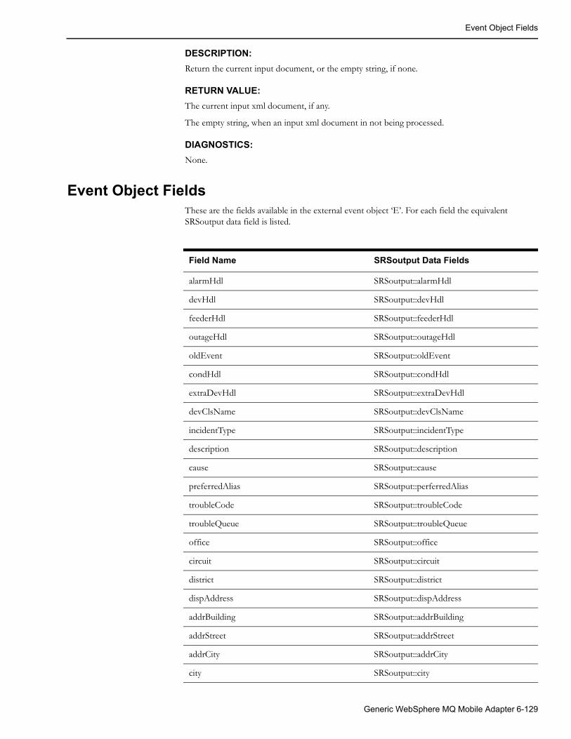
Event Object Fields
DESCRIPTION:
Return the current input document, or the empty string, if none.
RETURN VALUE:
The current input xml document, if any.
The empty string, when an input xml document in not being processed.
DIAGNOSTICS:
None.
Event Object FieldsThese are the fields available in the external event object ‘E’. For each field the equivalent SRSoutput data field is listed.
Field Name SRSoutput Data Fields
alarmHdl SRSoutput::alarmHdl
devHdl SRSoutput::devHdl
feederHdl SRSoutput::feederHdl
outageHdl SRSoutput::outageHdl
oldEvent SRSoutput::oldEvent
condHdl SRSoutput::condHdl
extraDevHdl SRSoutput::extraDevHdl
devClsName SRSoutput::devClsName
incidentType SRSoutput::incidentType
description SRSoutput::description
cause SRSoutput::cause
preferredAlias SRSoutput::perferredAlias
troubleCode SRSoutput::troubleCode
troubleQueue SRSoutput::troubleQueue
office SRSoutput::office
circuit SRSoutput::circuit
district SRSoutput::district
dispAddress SRSoutput::dispAddress
addrBuilding SRSoutput::addrBuilding
addrStreet SRSoutput::addrStreet
addrCity SRSoutput::addrCity
city SRSoutput::city
Generic WebSphere MQ Mobile Adapter 6-129
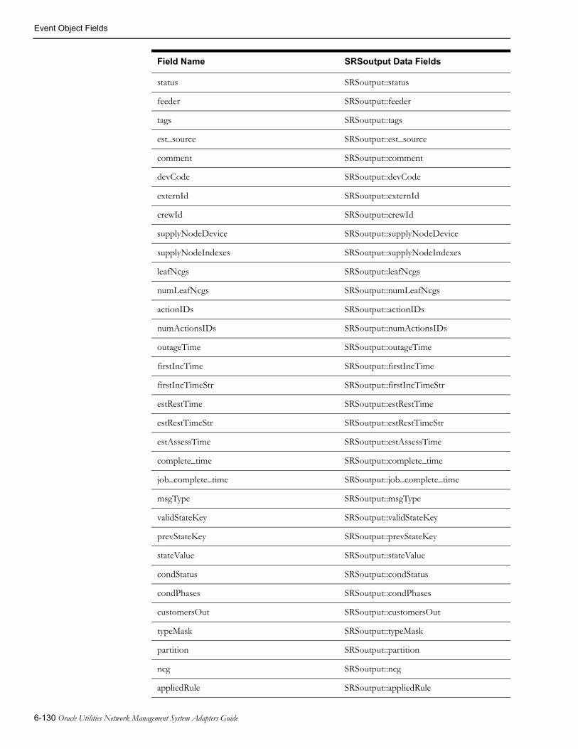
Event Object Fields
status SRSoutput::status
feeder SRSoutput::feeder
tags SRSoutput::tags
est_source SRSoutput::est_source
comment SRSoutput::comment
devCode SRSoutput::devCode
externId SRSoutput::externId
crewId SRSoutput::crewId
supplyNodeDevice SRSoutput::supplyNodeDevice
supplyNodeIndexes SRSoutput::supplyNodeIndexes
leafNcgs SRSoutput::leafNcgs
numLeafNcgs SRSoutput::numLeafNcgs
actionIDs SRSoutput::actionIDs
numActionsIDs SRSoutput::numActionsIDs
outageTime SRSoutput::outageTime
firstIncTime SRSoutput::firstIncTime
firstIncTimeStr SRSoutput::firstIncTimeStr
estRestTime SRSoutput::estRestTime
estRestTimeStr SRSoutput::estRestTimeStr
estAssessTime SRSoutput::estAssessTime
complete_time SRSoutput::complete_time
job_complete_time SRSoutput::job_complete_time
msgType SRSoutput::msgType
validStateKey SRSoutput::validStateKey
prevStateKey SRSoutput::prevStateKey
stateValue SRSoutput::stateValue
condStatus SRSoutput::condStatus
condPhases SRSoutput::condPhases
customersOut SRSoutput::customersOut
typeMask SRSoutput::typeMask
partition SRSoutput::partition
ncg SRSoutput::ncg
appliedRule SRSoutput::appliedRule
Field Name SRSoutput Data Fields
6-130 Oracle Utilities Network Management System Adapters Guide

Event Object Fields
priority SRSoutput::priority
custCall SRSoutput::custCall
pri_w SRSoutput::pri_w
pri_sw SRSoutput::pri_sw
pri_p SRSoutput::pri_p
pri_e SRSoutput::pri_e
custCrit SRSoutput::custCrit
crit_1 SRSoutput::crit_1
crit_2 SRSoutput::crit_2
crit_3 SRSoutput::crit_3
crit_tot SRSoutput::crit_tot
revenue SRSoutput::revenue
numSndDev SRSoutput:: numSndDev
numSupplied SRSoutput::numSupplied
outageRef SRSoutput::outageRef
oldCondID SRSoutput::oldCondID
sort_col_1 SRSoutput::sort_col_1
sort_col_2 SRSoutput::sort_col_2
sort_col_3 SRSoutput::sort_col_3
sort_col_4 SRSoutput::sort_col_4
sort_col_5 SRSoutput::sort_col_5
sort_col_6 SRSoutput::sort_col_6
sort_col_7 SRSoutput::sort_col_7
sort_col_8 SRSoutput::sort_col_8
sort_col_9 SRSoutput::sort_col_9
life_support SRSoutput::life_support
outage_type SRSoutput::outage_type
old_outage_type SRSoutput::old_outage_type
group_type SRSoutput::group_type
messages SRSoutput::messages
customer_phone SRSoutput::customer_phone
numb SRSoutput::numb
inc_outage SRSoutput::inc_outage
Field Name SRSoutput Data Fields
Generic WebSphere MQ Mobile Adapter 6-131

Event Object Fields
devAlias SRSoutput::devAlias
customerName SRSoutput::customerName
rule_set SRSoutput::rule_set
crit_k SRSoutput::crit_k
crit_c SRSoutput::crit_c
crit_d SRSoutput::crit_d
from_str SRSoutput::from_str
mergedEvents SRSoutput::mergedEvent
numMerged SRSoutput::numMerged
hasClue SRSoutput::hasClue
ctrlZoneHdl1 SRSoutput::ctrlZoneHdl1
ctrlZoneHdl2 SRSoutput::ctrlZoneHdl2
ctrlZoneHdl3 SRSoutput::ctrlZoneHdl3
ctrlZoneHdl4 SRSoutput::ctrlZoneHdl4
ctrlZoneHdl5 SRSoutput::ctrlZoneHdl5
ctrlZoneHdl6 SRSoutput::ctrlZoneHdl6
ctrlZoneName1 SRSoutput::ctrlZoneName1
ctrlZoneName2 SRSoutput::ctrlZoneName2
ctrlZoneName3 SRSoutput::ctrlZoneName3
ctrlZoneName4 SRSoutput::ctrlZoneName4
ctrlZoneName5 SRSoutput::ctrlZoneName5
ctrlZoneName6 SRSoutput::ctrlZoneName6
who_responsible SRSoutput::who_responsible
who_completed SRSoutput::who_completed
resp_modify_time SRSoutput:: resp_modify_time
xRef SRSoutput::xRef
yRef SRSoutput::yRef
highestIncPri SRSoutput::highestIncPri
referralGroup SRSoutput::referralGroup
who SRSoutput::who
firstCrewTime SRSoutput::firstCrewTime
additionalDevHdls SRSoutput::additionalDevHdls
additionalCondHdls SRSoutput::additionalCondHdls
Field Name SRSoutput Data Fields
6-132 Oracle Utilities Network Management System Adapters Guide
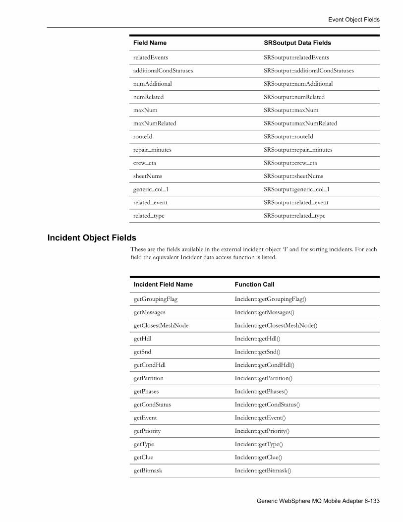
Event Object Fields
Incident Object FieldsThese are the fields available in the external incident object ‘I’ and for sorting incidents. For each field the equivalent Incident data access function is listed.
relatedEvents SRSoutput::relatedEvents
additionalCondStatuses SRSoutput::additionalCondStatuses
numAdditional SRSoutput::numAdditional
numRelated SRSoutput::numRelated
maxNum SRSoutput::maxNum
maxNumRelated SRSoutput::maxNumRelated
routeId SRSoutput::routeId
repair_minutes SRSoutput::repair_minutes
crew_eta SRSoutput::crew_eta
sheetNums SRSoutput::sheetNums
generic_col_1 SRSoutput::generic_col_1
related_event SRSoutput::related_event
related_type SRSoutput::related_type
Field Name SRSoutput Data Fields
Incident Field Name Function Call
getGroupingFlag Incident::getGroupingFlag()
getMessages Incident::getMessages()
getClosestMeshNode Incident::getClosestMeshNode()
getHdl Incident::getHdl()
getSnd Incident::getSnd()
getCondHdl Incident::getCondHdl()
getPartition Incident::getPartition()
getPhases Incident::getPhases()
getCondStatus Incident::getCondStatus()
getEvent Incident::getEvent()
getPriority Incident::getPriority()
getType Incident::getType()
getClue Incident::getClue()
getBitmask Incident::getBitmask()
Generic WebSphere MQ Mobile Adapter 6-133

Event Object Fields
getTotalPriority Incident::TotalPriority()
getLifeSupportCode Incident::getLifeSupportCode()
getCriticalCustomer Incident::getCriticalCustomer()
getCallCancelInd Incident::getCallCancelInd()
getCallbackLateInd Incident::getCallbackLateInd()
getTcode Incident::getTcode()
getTroubleQueue Incident::getTroubleQueue()
getShortDesc Incident::getShortDesc()
getDrvInst Incident::getDrvInst()
getCID Incident::getCID()
getCustomerName Incident::getCustomerName()
getCtype Incident::getCtype()
getAddrBuilding Incident::getAddrBuilding()
getAddrStreet Incident::getAddrStreet()
getAddrCity Incident::getAddrCity()
getOrderNumber Incident::getOrderNumber()
getGenernalArea Incident::getGeneralArea()
getMeterId Incident::getMeterId()
getDeviceAlias Incident::getDeviceAlias()
getNcg Incident::getNcg()
getExternalId Incident::getExternalId()
getInputTime Incident::getInputTime()
getCallbackRequest Incident::getCallbackRequest()
getCallbackDataTime Incident::getCallbackDataTime()
getOpComment Incident::getOpComment()
getCustomerPhone Incident::getCustomerPhone()
alternatePhone Incident::alternatePhone()
userName Incident::userName()
getXRef Incident::getXRef()
getYRef Incident::getYRef()
getExternallySent Incident::getExternallySent()
getAONFlag Incident::getAONFlag()
getROCFlag Incident::getROCFlag()
Incident Field Name Function Call
6-134 Oracle Utilities Network Management System Adapters Guide

Event Object Fields
Permanent Order Object FieldsThese are the fields that are always available in the external order object ‘O’. These fields are read-only. The contents of each field are listed.
Incident Field Name Contents
order The order’s Handle
event The order’s key event Handle
eventless A boolean indicating that the order has lost all it’s events. This is true for a period between the time the key event became non-existent and the time the order is completed, often as a result of an EventNonexistent trigger triggering an Output Document that completes the order.
Permanent Relationship Object FieldsThese are the fields that are always available in the external relationship object ‘O’. These fields are read-only. The contents of each field are listed.
Incident Field Name Contents
relation The relationship’s Handle
event The relationship’s key (parent) event Handle
type The relationship’s type
Active A boolean indicating that the relationship is active. This is false for a period between the time the relationship was deleted in Oracle Utilities Network Management System and the time the relation is deleted, often as a result of a RelationDeleted trigger triggering an Output Document that deletes the relation.
active Incident::active()
Incident Field Name Function Call
Generic WebSphere MQ Mobile Adapter 6-135

Event Object Fields
6-136 Oracle Utilities Network Management System Adapters Guide

Chapter 7SCADA Measurements
This chapter includes the following topics:
• Introduction to scadapop
• Configuration
• Recaching Measurements
• Information Model
Introduction to scadapopThe Oracle Utilities Network Management System (NMS) can accept updates from a variety of external (outside) Supervisory Control And Data Acquisition (SCADA) systems. Multiple external SCADA systems can be connected to a single NMS instance. If necessary a different adapter can be used for each external SCADA a utility wishes to connect to. For example one SCADA system might use the ICCPAdapter, one the generic NMS SCADA adapter (RTAdapter) another might use a project specific or custom SCADA adapter. In all cases the NMS objects and attributes that can be updated from each external SCADA adapter must be defined before NMS can accept input from these SCADA systems. This section describes one mechanism for populating the necessary configuration tables with objects and attribute information so the SCADA adapter can pass information into NMS.
Configuration
RDBMS ConfigurationTables involved:
• scada_measurements_st: standard SCADA measurements configuration table. This is a staging table used by DDService for populating the production SCADA measurement tables.
• digital_measurements: production SCADA measurements table for digital measurements. Only DDService should write to this table.
• analog_measurements: production SCADA measurements table for analog measurements. Only DDService should write to this table.
• scada_ids: RTAdapter SCADA definition table.
• scada_points: optional model build attribute table that is used by the scadapop executable - to help populate the scada_measurements_st staging table. If you want to use scadapop – you need to populate the scada_points table.
SCADA Measurements 7-1

Configuration
Note: The scada_points table only needs to be populated if using scadapop. It is normally populated via device class driven attribute population during the model build process.
To configure the standard SCADA input RDBMS staging table (scada_measurements_st) using scadapop follow the following steps:
Specify which model devices have SCADA (via scada_points table. The scada_points table is generally populated via attribute population during model build construction/update but can be populated after the fact by a custom (project specific) process. A generalization is made that each defined “SCADA” provides a consistent set of attributes for a given NMS object. For example SCADA_A might be defined to always provide a digital “status” and 3 analog values – A_Phase_Amps, B_Phase_Amps and C_Phase_Amps. SCADA_B might be defined to always provide digital “status” and 6 analog values. This generalization is made to simplify configuration. It is generally acceptable if the external SCADA system does not actually provide all SCADA measurements for all configured points – within reason – to simplify configuration.
There are generally two options for populating the scada_points table:
1. Populate scada_points RDBMS table via model build device attribute configuration.
This option involves populating two attributes in the scada_points table:
• scada_name: the name of the SCADA, as defined in scada_ids.scada_name (for example, RTAdapter).
• rtu_alias: SCADA unique identifier for reporting field device.
The rtu_alias must only be unique within a particular SCADA (scada_name). An individual rtu_alias may well report multiple analog values (AMP, VOLT, KVAR, etc.) as well as digital and/or status values.
To set up the scada_points table as a standard Network Management System attribute table generally involves the following RDBMS tables:
• device_attributes: generic model build attribute configuration table.
• scada_points: SCADA project specific attribute table.
2. Populate the scada_points RDBMS table via a project specific (post model build) process. This might involve selecting all the devices of a specific class from the alias_mapping table – for example.
Once the scada_points table is populated, the scadapop program can be used to expand the information in the scada_points table to fully populate the more generic scada_measurements_st staging table (see notes below for how to use scadapop).
Note: A given “field device” corresponds to a given scada_points.rtu_alias and would typically be a breaker of some kind (often reporting both device status and multiple analog values). It could also be a transformer reporting analog values with or without status or some other class of device with SCADA data.
Below are two example device_attributes table entries to support population of the scada_points table via standard model build attribute population (option 1 above). For more information on this process, please consult the Network Management System Model Build process documentation. These are examples only.
INSERT INTO device_attributes (DEVICE_CLS,ATTR_NAME,TABLE_NAME,COLUMN_NAME, ATTR_TYPE,LENGTH,
7-2 Oracle Utilities Network Management System Adapters Guide
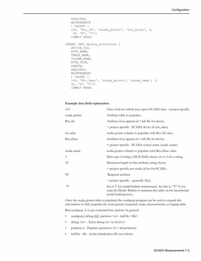
Configuration
REQUIRED,MAINTENANCE) VALUES (143, 'Rtu_Id', 'scada_points', 'rtu_alias', 3, 32, 'N', 'Y');COMMIT WORK;
INSERT INTO device_attributes (DEVICE_CLS,ATTR_NAME,TABLE_NAME,COLUMN_NAME, ATTR_TYPE,LENGTH,REQUIRED,MAINTENANCE) VALUES (143, 'Rtu_Desc', 'scada_points', 'scada_name', 3,32, 'N', 'Y');COMMIT WORK;
Example data field explanation:
143 Class of device which may report SCADA data. + project specific
scada_points Attribute table to populate.
Rtu_Id Attribute id as appears in *.mb file for device.
+ project specific - SCADA device id (rtu_alias).
rtu_alias scada_points column to populate with Rtu_Id value.
Rtu_Desc Attribute id as appears in *.mb file for device.
+ project specific - SCADA system name (scada_name).
scada_name scada_points column to populate with Rtu_Desc value.
3 Data type of string (ASCII field); always set to 3 for a string
32 Maximum length of this attribute string (bytes)
+ project specific per scada_id len for SCADA.
'N' Required attribute
+ project specific – generally (N)o.
'Y' Set to Y for model builder maintenance. Set this to “Y” if you want the Model Builder to maintain this table via the incremental model build process.
Once the scada_points table is populated the scadapop program can be used to expand this information to fully populate the more generic (required) scada_measurements_st staging table.
Run scadapop -h to get command line options. In general:
• scadapop [-debug [n]] -partition <n> -initFile <file>
• debug <n> - Turns debug on <to level n>
• partition n - Populate partition n (0 = all partitions)
• initFile - file - rti.dat initialization file (see below)
SCADA Measurements 7-3

Configuration
The rti.dat file is the configuration file used by the scadapop program. Based on data in this file, and entries in the scada_points table, scadapop populates the standard SCADA configuration (RDBMS) staging table:
• scada_measurements_st
The scada_points table contains a record (row) for each device in the Network Management System model that has SCADA information associated with it. Each record has a “scada_name” column which, in order to populate one of the measurements tables, must match a “SCADA_Name” keyword in this configuration file. Where there is a match a row is populated in the scada_measurements_st staging table for each defined attribute.
• Each defined Digital attribute for a given SCADA_Name has a measurement_type of “D” in the scada_measurements_st table.
• Each defined Analog attribute for a given SCADA_Name has a measurement_type of “A” in the scada_measurements_st table.
The syntax rules for the rti.dat file are:
• Lines with a leading # are treated as comments (ignored).
• Leading blank space is ignored.
• Only the first two non-blank tokens on a line are recognized.
• The remaining tokens are treated as comments (ignored).
• Blank lines ok. (ignored)
• Attributes are associated to last defined SCADA_Name.
The following keywords exist - they must match EXACTLY:
• SCADA_Name:
• Analog:
• Digital:
Note: The colon “:” character is a keyword delimiter. The colon must appear as the first character after the keyword in order for the keyword to be recognized.
Example rti.dat file:
SCADA_Name: USADigital: status (Switch Position or “Status”)Analog: Amps_AAnalog: Amps_BAnalog: Amps_CAnalog: Volts_AAnalog: Volts_BAnalog: Volts_C
Example scadapop commands:
scadapop -partition 0 -initFile ${CES_DATA_FILES}/OPAL_rti.datscadapop -partition 3111 -initFile rti.dat -debug
7-4 Oracle Utilities Network Management System Adapters Guide

Information Model
Recaching MeasurementsTo load the SCADA measurements staging table into the production (run-time) SCADA measurements tables, the following command must be run:
UpdateDDS -recacheMeasurements
When this command is invoked, DDService will merge the scada_measurements_st table into the analog_measurements and digital_measurements tables (adding and removing rows as necessary) and load the updated analog_measurements and digital_measurements tables into memory.
When new measurements are added, all fields in the production measurements table are populated from the staging table.
When existing measurements are updated, all fields are copied from the staging table except the following columns because these columns can contain operator entered data (operator override values for example) - and should not be overwritten. Indeed this is the primary reason for using the staging table - to avoid overwriting these run-time columns:
• QUALITY
• VALUE
• ACTIVE
Information Model
Database Schema
SCADA_IDS Database Table
The schema for this table is defined in ces_schema_scada.sql file.
The script, OPAL_scada_ids.sql, populates generic SCADA sources for the OPAL model. A source is any SCADA system that can provide information to the adapter. There could be one SCADA source defined for each of multiple SCADA vendors, or a utility may choose to divide their territory into multiple regions, with each region acting as a separate SCADA source. Each SCADA source must have a name as well as a unique integer ID.
Column Data Type Description
ID NUMBER Numeric identifier for each “SCADA source” that we want RTI to process.
SCADA_NAME VARCHAR2(32) Name for the SCADA source
ADAPTER_TYPE VARCHAR2(32) Adapter type for this SCADA source.
ACTIVE VARCHAR2(1) Is the adapter active (Y/N)
SCADA_IDS
SCADA_POINTS Database Table
The SCADA_POINTS table contains a row for each device in the Oracle Utilities Network Management System operations database that has SCADA information associated with it. Each record has a “scada_name” column which, in order to populate one of the measurements tables,
SCADA Measurements 7-5

Information Model
must match a “SCADA_Name:” keyword in the rti.dat configuration file (see notes above for example rti.dat population). Where there is a match, a row is populated in the appropriate (digital or analog) measurements table for each defined attribute.
The SCADA_POINTS table is normally populated via device driven attribute population during the model build process. It is a staging table for the RTI population process. It is not accessed during adapter execution.
The schema for this table can be found in the file ces_retain_scada.sql
SCADA_POINTS
Column Data Type Description
H_CLS SMALLINT Object handle class
H_IDX INTEGER Object handle index
SCADA_NAME VARCHAR2(32) SCADA system name (Rtu_Desc)
RTU_ALIAS VARCHAR2(32) SCADA point name (Rtu_Id)
PARTITION INTEGER Partition of this object
BIRTH DATE Date object activated into the model
BIRTH_PATCH INTEGER Patch which activated this object
DEATH DATE Date object de-activated into the model
DEATH_PATCH INTEGER Patch which de-activated this object
ACTIVE VARCHAR2(1) Active flag (Y/N)
SCADA_MEASUREMENTS_ST Database Table
The scada_measurements_st table is a staging table used to help populate the analog_measurements and digital_measurements (production) tables. The schema for this table can be found in the file ces_retain_scada.sql.
SCADA_MEASUREMENTS_ST
Column Data Type Description
H_CLS SMALLINT Object handle class
H_IDX INTEGER Object handle index
PARTITION INTEGER Object partition
ATTRIBUTE SMALLINT Data attribute index (from ATTRIBUTES table)
TTL SMALLINT Time-To-Live Value
LIMIT_GROUP_ID INTEGER Object limit group
RTI_ALIAS VARCHAR2(128) RTI device measurement name
7-6 Oracle Utilities Network Management System Adapters Guide

Information Model
RTI_ALIAS_A VARCHAR2(128) RTI device measurement name for phase A. Only applies for digital measurements and only used by the MultiSpeak SCADA adapter.
RTI_ALIAS_B VARCHAR2(128) RTI device measurement name for phase B. Only applies for digital measurements and only used by the MultiSpeak SCADA adapter.
RTI_ALIAS_C VARCHAR2(128) RTI device measurement name for phase C. Only applies for digital measurements and only used by the MultiSpeak SCADA adapter.
SCADA_ID INTEGER SCADA source identifier - matches scada_ids.id
RTU_ID VARCHAR2(32) RTU ID - unique name within SCADA system.
QUALITY INTEGER Quality code
VALUE FLOAT Manual Replace Value
UPDATE_FLAG INTEGER Manual Replace Flag
ICCP_OBJECT VARCHAR2(32) ICCP mms object name
DISPLAY_ID VARCHAR2(64) ID for display call up
CONTROLLABLE VARCHAR2(1) Is this row controllable
ACTIVE VARCHAR2(1) Is this row active
SOURCE VARCHAR2(33) Source of measurements
COMMENTS VARCHAR2(512) Comment associated with
OFF_NOMINAL_TIME
DATE Time quality went off-nominal
NORMAL_STATE INTEGER Normal state for measure. Only used for digital measurements.
MEASUREMENT_TYPE
VARCHAR2(1) Measurement Type:A -- Analog measurement
D -- Digital measurement
Column Data Type Description
SCADA Measurements 7-7

Information Model
7-8 Oracle Utilities Network Management System Adapters Guide

Chapter 8Generic SCADA Adapter
This chapter includes the following topics:
• Introduction
• Generic SCADA Adapter Configuration
• Software Configuration
• Information Model
IntroductionThe Generic SCADA Adapter (executable name: RTAdapter) is an Oracle Utilities Network Management System interfacing adapter that can be used to interface to external SCADA systems. Generally one RTAdapter process is configured to communicate with each external SCADA system. Each external SCADA system must write some form of “scan file” to a defined (dedicated) directory (or RDBMS table) that RTAdapter can access in read/write mode. The “scan files” are read out of the named directory (or RDBMS table) by RTAdapter on a first-in-first-out basis (to support queuing of updates). The form of the scan files can be configured (to some degree) for each SCADA interface.
Generic SCADA Adapter Configuration
OverviewThis section is used to guide the user in the configuration of the Oracle Utilities Network Management System Generic SCADA Adapter. The following are assumed to be true before the adapter is installed:
• Oracle database access has been confirmed.
• ISIS messaging bus has been installed and verified.
• Oracle Utilities Network Management System is installed and functional.
Generic SCADA Adapter 8-1
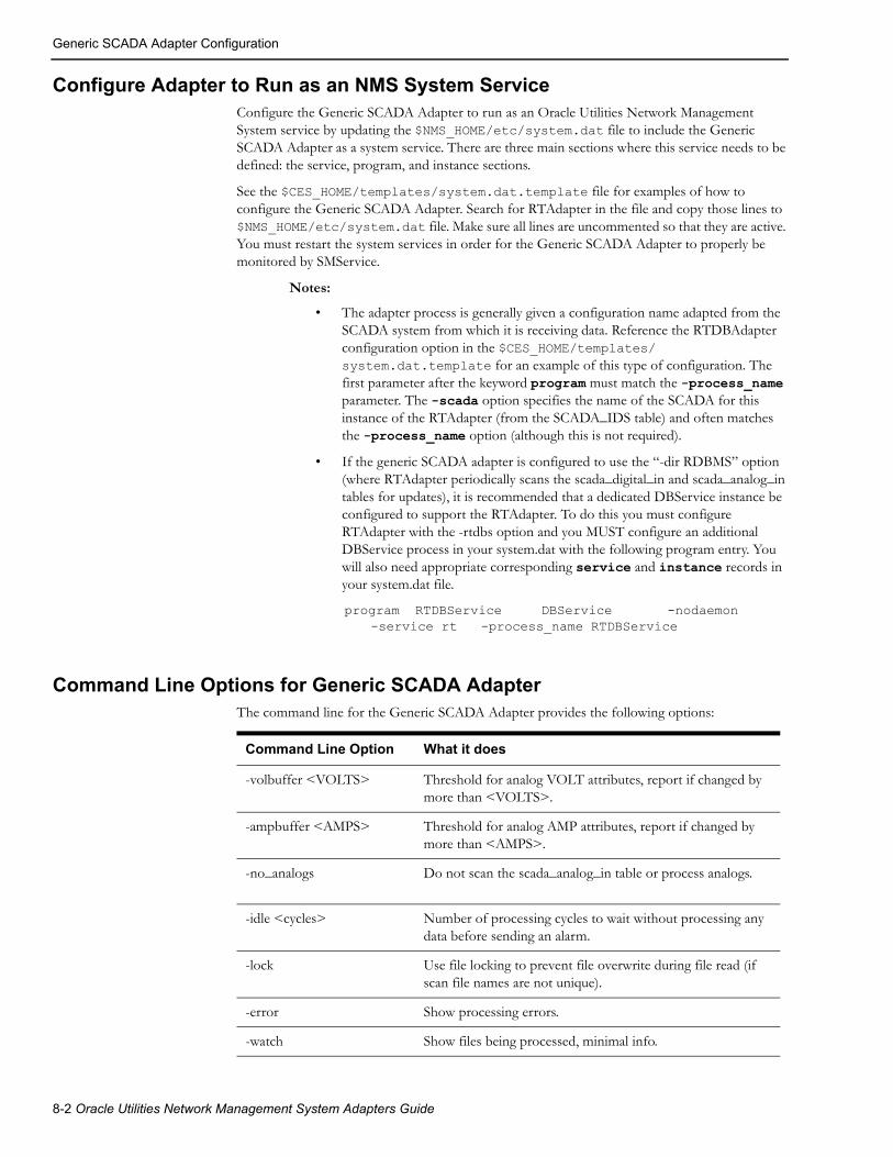
Generic SCADA Adapter Configuration
Configure Adapter to Run as an NMS System ServiceConfigure the Generic SCADA Adapter to run as an Oracle Utilities Network Management System service by updating the $NMS_HOME/etc/system.dat file to include the Generic SCADA Adapter as a system service. There are three main sections where this service needs to be defined: the service, program, and instance sections.
See the $CES_HOME/templates/system.dat.template file for examples of how to configure the Generic SCADA Adapter. Search for RTAdapter in the file and copy those lines to $NMS_HOME/etc/system.dat file. Make sure all lines are uncommented so that they are active. You must restart the system services in order for the Generic SCADA Adapter to properly be monitored by SMService.
Notes:
• The adapter process is generally given a configuration name adapted from the SCADA system from which it is receiving data. Reference the RTDBAdapter configuration option in the $CES_HOME/templates/system.dat.template for an example of this type of configuration. The first parameter after the keyword program must match the -process_name parameter. The -scada option specifies the name of the SCADA for this instance of the RTAdapter (from the SCADA_IDS table) and often matches the -process_name option (although this is not required).
• If the generic SCADA adapter is configured to use the “-dir RDBMS” option (where RTAdapter periodically scans the scada_digital_in and scada_analog_in tables for updates), it is recommended that a dedicated DBService instance be configured to support the RTAdapter. To do this you must configure RTAdapter with the -rtdbs option and you MUST configure an additional DBService process in your system.dat with the following program entry. You will also need appropriate corresponding service and instance records in your system.dat file.
program RTDBService DBService -nodaemon -service rt -process_name RTDBService
Command Line Options for Generic SCADA AdapterThe command line for the Generic SCADA Adapter provides the following options:
Command Line Option What it does
-volbuffer <VOLTS> Threshold for analog VOLT attributes, report if changed by more than <VOLTS>.
-ampbuffer <AMPS> Threshold for analog AMP attributes, report if changed by more than <AMPS>.
-no_analogs Do not scan the scada_analog_in table or process analogs.
-idle <cycles> Number of processing cycles to wait without processing any data before sending an alarm.
-lock Use file locking to prevent file overwrite during file read (if scan file names are not unique).
-error Show processing errors.
-watch Show files being processed, minimal info.
8-2 Oracle Utilities Network Management System Adapters Guide

Generic SCADA Adapter Configuration
-debug Enable debugging.
-operate Operate (change status of) model devices, otherwise generates pseudo alarms only.
-process_name ISIS process name for this process. If the first parameter after the keyword program in the first column of the system.dat file is something other than the second parameter - then you must set the -process_name option to the same string as the first parameter. This is only generally necessary if you need to run more than one instance of RTAdapter or you want RTAdapter to be known as some other name within the ISIS messaging bus. ISIS process names must be unique.
-controls Call the project/SCADA specific rti_project.ces script when an outbound control request (open/close) is made. This script can be customized to help trigger an action (some type of control request) on external system. Generally for testing.
-offline For testing purposes - when a control request is received - simulate the external SCADA system and operate the device.
-dir <directory> Value either directing RTAdapter to the directory containing scada data scan files or if set to 'RDBMS' enabling the scada_digital_in/scada_analog_in database polling functionality. (Required)
-interval <interval> Seconds between file processing cycles. (Required)
-scada <scada> SCADA source name. (Required)
-delimiter <char> Allows a project to override the default (|) input file delimiter character with the specified character.
-rtdbs Instructs RTAdapter to use a dedicated DBService instance. This is recommended if you are using the -dir RDBMS option to periodically scan scada_digital_in and scada_analog_in tables. To use this option you must have a DBService instance configured with a process name of rtdbs – see note above on RTDBService.
-retain Retain data in scada_digital_in table after it is processed. Generally for validation/debug - not general purpose production use.
Command Line Option What it does
Generic SCADA Adapter 8-3

Software Configuration
Software Configuration
OverviewThe interface comes with a configuration support tool (scadapop) that can be used to help populate the standard SCADA configuration tables for incoming SCADA data (analog_measurements and digital_measurements). The scadapop process can be used to provide initial population of these tables.
Adapter Configuration
RDBMS configuration:
Tables involved:
• digital_measurements: standard SCADA runtime configuration table for digital measurements. Persistent storage for digital measurement specific quality codes and/or manually entered values.
• analog_measurements: standard SCADA runtime table for analog_measurements. Persistent storage for analog measurement specific quality codes and/or manually entered values.
• scada_measurements_st: SCADA configuration staging table.
Note: The scada_measurements_st staging table can be populated via the scadapop process or by a project specific population mechanism. This table can be truncated and repopulated at will while DDService is active (running). The UpdateDDS -recacheMeasures command will send a message to DDService to merge updates from the scada_measurements_st staging table into the analog_measurements and/or digital_measurements runtime SCADA tables - preserving any existing quality codes and/or stored data values.
• scada_ids: RTAdapter/scadapop SCADA definition table - required for both.
• scada_states: RTAdapter string state to integer mapping - required.
• scada_synonyms: RTAdapter scada data attribute value mapping - required.
• scada_analog_in: RTAdapter polling table can be used to queue incoming analog SCADA updates - optional.
Note: The RTAdapter process does not require any population into the scada_analog_in table. The use of scada_digital_in is entirely optional but is generally used in conjunction with scada_analog_in.
• scada_digital_in: RTAdapter polling table can be used to queue incoming digital SCADA updates - optional.
Note: The RTAdapter process does not require any population into the scada_digital_in table. The use of scada_digital_in is entirely optional but is generally used in conjunction with scada_analog_in.
• scada_points: optional scadapop staging table - to help populate scada_measurements_st.
Note: The RTAdapter process does not require any population into the scada_points table. The use of scada_points as a staging table is merely one solution for the ultimate problem of configuring the required SCADA measurements staging table (scada_measurements_st). The use of scadapop is entirely optional.
8-4 Oracle Utilities Network Management System Adapters Guide
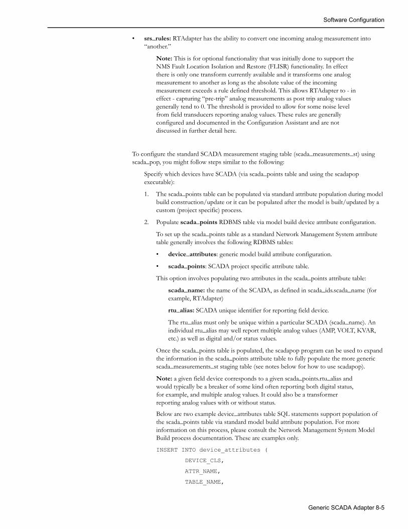
Software Configuration
• srs_rules: RTAdapter has the ability to convert one incoming analog measurement into “another.”
Note: This is for optional functionality that was initially done to support the NMS Fault Location Isolation and Restore (FLISR) functionality. In effect there is only one transform currently available and it transforms one analog measurement to another as long as the absolute value of the incoming measurement exceeds a rule defined threshold. This allows RTAdapter to - in effect - capturing “pre-trip” analog measurements as post trip analog values generally tend to 0. The threshold is provided to allow for some noise level from field transducers reporting analog values. These rules are generally configured and documented in the Configuration Assistant and are not discussed in further detail here.
To configure the standard SCADA measurement staging table (scada_measurements_st) using scada_pop, you might follow steps similar to the following:
Specify which devices have SCADA (via scada_points table and using the scadapop executable):
1. The scada_points table can be populated via standard attribute population during model build construction/update or it can be populated after the model is built/updated by a custom (project specific) process.
2. Populate scada_points RDBMS table via model build device attribute configuration.
To set up the scada_points table as a standard Network Management System attribute table generally involves the following RDBMS tables:
• device_attributes: generic model build attribute configuration.
• scada_points: SCADA project specific attribute table.
This option involves populating two attributes in the scada_points attribute table:
scada_name: the name of the SCADA, as defined in scada_ids.scada_name (for example, RTAdapter)
rtu_alias: SCADA unique identifier for reporting field device.
The rtu_alias must only be unique within a particular SCADA (scada_name). An individual rtu_alias may well report multiple analog values (AMP, VOLT, KVAR, etc.) as well as digital and/or status values.
Once the scada_points table is populated, the scadapop program can be used to expand the information in the scada_points attribute table to fully populate the more generic scada_measurements_st staging table (see notes below for how to use scadapop).
Note: a given field device corresponds to a given scada_points.rtu_alias and would typically be a breaker of some kind often reporting both digital status, for example, and multiple analog values. It could also be a transformer reporting analog values with or without status.
Below are two example device_attributes table SQL statements support population of the scada_points table via standard model build attribute population. For more information on this process, please consult the Network Management System Model Build process documentation. These are examples only.
INSERT INTO device_attributes (
DEVICE_CLS,
ATTR_NAME,
TABLE_NAME,
Generic SCADA Adapter 8-5

Software Configuration
COLUMN_NAME,
ATTR_TYPE,
LENGTH,
REQUIRED,
MAINTENANCE
) VALUES (
143, 'Rtu_Id', 'scada_points', 'rtu_alias', 3, 32, 'N', 'Y');
COMMIT WORK;
INSERT INTO device_attributes
DEVICE_CLS,
ATTR_NAME,
TABLE_NAME,
COLUMN_NAME,
ATTR_TYPE,
LENGTH,
REQUIRED,
MAINTENANCE
) VALUES (
143, 'Rtu_Desc', 'scada_points', 'scada_name', 3, 32, 'N', 'Y');
COMMIT WORK;
Example device_attribute model attribute table - data field explanation:
143 Class of device which may report SCADA data. + project specific
scada_points Model attribute table to populate.
Rtu_Id Attribute id as appears in *.mb file for device - project specific.
rtu_alias Table scada_points column to populate with Rtu_Id value.
Rtu_Desc Attribute id as appears in *.mb file for device.
scada_name scada_points column to populate with Rtu_Desc value.
3 Data type of string (ASCII field) always a 3 for a string.
32 Maximum length of this attribute string (bytes).
'N' Required attribute - project specific generally ‘N’ (no).
'Y' Set to Y for model builder maintenance. Set this to ‘Y’ if you want the Model Builder to maintain this table via the incremental model build process.
Once the scada_points table is populated the scadapop program can be used to expand this information to fully populate the scada_measurements_st staging tables.
8-6 Oracle Utilities Network Management System Adapters Guide

Software Configuration
Run scadapop -h to get command line options. In general:
• scadapop [-debug [n]] -partition <n> -initFile <file>
• debug <n> - Turns debug on <to level n>
• partition n - Populate partition n (0 = all partitions)
• initFile <configuration - file> - rti.dat configuration file (see below)
The rti.dat file is the configuration file used by the scadapop program. Based on data in this file, and entries in the scada_points table, scadapop populates the scada_measurements_st staging table.
The scada_points table contains a single record (row) for each device in the Network Management System model that has SCADA information associated with it. Each record has a “scada_name” column which, in order to populate the scada_measurements_st staging table, must match a “SCADA_Name” keyword in the configuration file specified via the scadapop -initFile<configuration file> option.
The syntax rules for the rti.dat file are:
• Lines with a leading # are treated as comments (ignored).
• Leading blank space is ignored.
• Only the first two non-blank tokens on a line are recognized.The remaining tokens are treated as comments (ignored).
• Blank lines are okay.
• Attributes are associated to last defined SCADA_Name.
Keywords (they must match EXACTLY):
• SCADA_Name:
• Analog:
• Digital:
Note: The colon “:” character is a keyword delimiter. The colon must appear as the first character after the keyword in order for the keyword to be recognized.
Example rti.dat file:
SCADA_Name: RTAdapterDigital: status (Switch Position or “Status”)Analog: Amps_AAnalog: Amps_BAnalog: Amps_CAnalog: Volts_AAnalog: Volts_BAnalog: Volts_C
Example scadapop command line execution:
scadapop -partition 0 -initFile ${CES_DATA_FILES}/OPAL_rti.datTo populate the scada_measurements_st for all partitions.
scadapop -partition 3111 -initFile rti.dat -debugTo populate the scada_measurements_st for partitions 3111 plus debug.
Generic SCADA Adapter 8-7

Software Configuration
Other RTAdapter-specific RDBMS Population
The tables below are configuration tables that generally need to be populated via project specific sql scripts. Example configuration for these tables is provided for the Oracle (OPAL) model in $NMS_HOME/sql/OPAL_scada.sql.
scada_ids: RTAdapter name to unique integer value mapping.
• Generally used to map SCADA name to a unique integer id.
scada_states: RTAdapter string to integer mapping.
• Generally used to map topology state and/or quality code information
scada_synonyms: RTAdapter scada data attribute/synonym value mapping.
• Generally used to map SCADA reported attributes to Network Management System attributes.
Sample RTAdapter Configuration/Execution Sequence - File Based
To get RTAdapter up and running, the following general steps should suffice.
Start from the home directory for RTAdapter:
1. Login to Network Management System admin account with standard OPAL model configured and running.
2. Create RTAdapter specific RDBMS tables:
ISQL.ces product_schema_scada.sql
• creates scada_ids table
• creates scada_states table
• creates scada_synonyms table
ISQL.ces ces_retain_scada.sql
• creates scada_points table
• creates scada_analog_in table (only used with “-dir RDBMS” option)
• creates scada_digital_in table (only used with “-dir RDBMS” option)
3. The OPAL_scada.sql file contains sample population data for the scada_ids, scada_points, scada_synonyms and controls table for the OPAL model. You must modify and rename this file for your project.
ISQL.ces OPAL_scada.sql
4. Run “scadapop -partition 0 -initFile $CES_DATA_FILES/OPAL_rti.dat”
• This should populate scada_measurements_st staging table - confirm that you have entries in this table before moving to the next step.
5. Validate the RTAdapter is in the $NMS_HOME/etc/system.dat file (see directions above).
• Recommend using -watch and possibly the -debug option to start; helps to identify configuration issues.
6. If the system.dat file is using the $NMS_SCADA_SCAN_FILE_DIR environment variable to specify the SCADA scan file directory, make sure this environment variable points to a directory that the RTAdapter process can both read and write. Generally, this means a directory owned by the id that is executing RTAdapter. For example, mkdir ~/scada. At the same time, suggest creating a test data holding directory (for example, mkdir ~/scada/tst).
8-8 Oracle Utilities Network Management System Adapters Guide
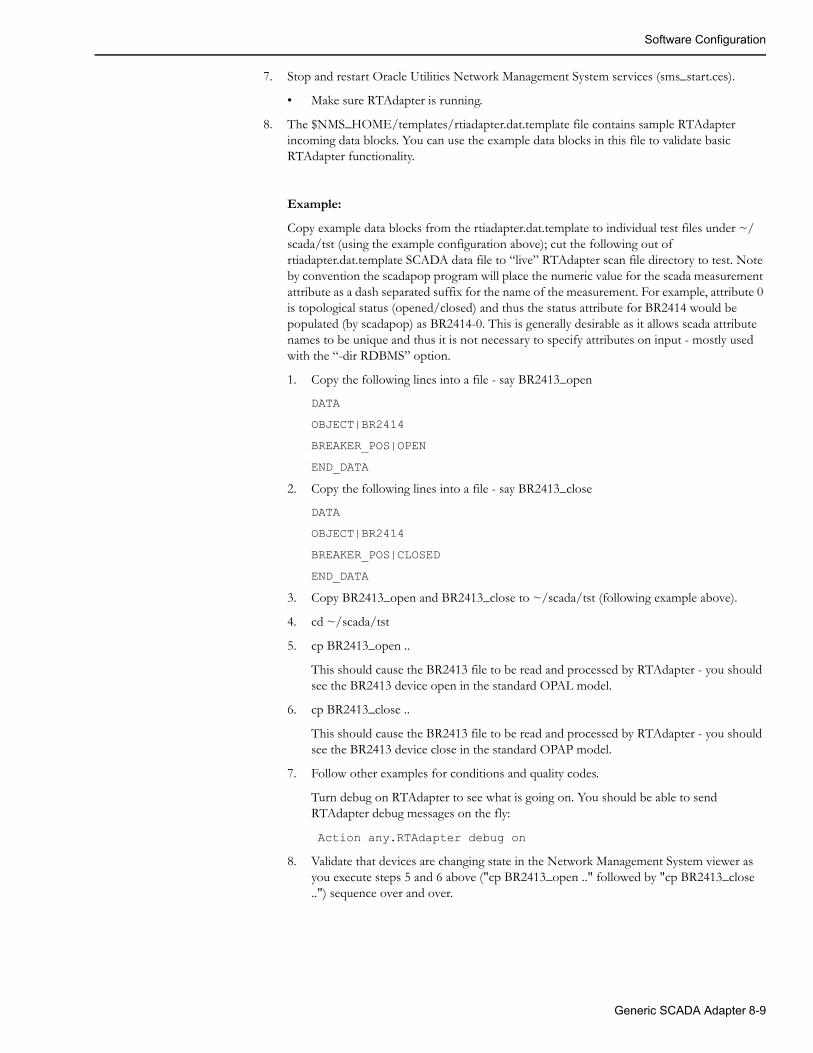
Software Configuration
7. Stop and restart Oracle Utilities Network Management System services (sms_start.ces).
• Make sure RTAdapter is running.
8. The $NMS_HOME/templates/rtiadapter.dat.template file contains sample RTAdapter incoming data blocks. You can use the example data blocks in this file to validate basic RTAdapter functionality.
Example:
Copy example data blocks from the rtiadapter.dat.template to individual test files under ~/scada/tst (using the example configuration above); cut the following out of rtiadapter.dat.template SCADA data file to “live” RTAdapter scan file directory to test. Note by convention the scadapop program will place the numeric value for the scada measurement attribute as a dash separated suffix for the name of the measurement. For example, attribute 0 is topological status (opened/closed) and thus the status attribute for BR2414 would be populated (by scadapop) as BR2414-0. This is generally desirable as it allows scada attribute names to be unique and thus it is not necessary to specify attributes on input - mostly used with the “-dir RDBMS” option.
1. Copy the following lines into a file - say BR2413_open
DATA
OBJECT|BR2414
BREAKER_POS|OPEN
END_DATA
2. Copy the following lines into a file - say BR2413_close
DATA
OBJECT|BR2414
BREAKER_POS|CLOSED
END_DATA
3. Copy BR2413_open and BR2413_close to ~/scada/tst (following example above).
4. cd ~/scada/tst
5. cp BR2413_open ..
This should cause the BR2413 file to be read and processed by RTAdapter - you should see the BR2413 device open in the standard OPAL model.
6. cp BR2413_close ..
This should cause the BR2413 file to be read and processed by RTAdapter - you should see the BR2413 device close in the standard OPAP model.
7. Follow other examples for conditions and quality codes.
Turn debug on RTAdapter to see what is going on. You should be able to send RTAdapter debug messages on the fly:
Action any.RTAdapter debug on
8. Validate that devices are changing state in the Network Management System viewer as you execute steps 5 and 6 above ("cp BR2413_open .." followed by "cp BR2413_close ..") sequence over and over.
Generic SCADA Adapter 8-9

Software Configuration
Sample RTAdapter Configuration/Execution Sequence - RDBMS Table Polling Based
To get RTAdapter to use the RDBMS queue table mechanism (rather than the earlier file based polling), the following general steps should suffice.
Start from the home directory for RTAdapter:
1. Follow steps (1-5) as noted above for the file based polling example above.
2. In the ~/etc/system.dat configuration file verify the RTAdapter option -dir RDBMS. If the -dir option is set to a directory (rather than the keyword RDBMS),. RDBMS polling will NOT be enabled
3. Recommend using -watch and, possibly, the -debug option to help identify configuration issues.
4. Stop and restart Oracle Utilities Network Management System services (sms_start.ces).
5. Make sure RTAdapter is running.
6. Insert row into SCADA_DIGITAL_IN table either using alias or h_cls and h_idx with status = ‘N’. The primary key on the scada_digital_in table is the id column – which is generally populated by a trigger on the scada_digital_in table that fires on insert and populates the id column with the next value in a sequence.
Example sql statement:
INSERT into scada_digital_in (alias,phasesoperation,operation_date,qualitysource,status) VALUES ( ‘BR2414-0', /* Unique attribute measurement name from scada_measurements_st */ '7', /* Phase bitmask - 7=ABC, 1=A, 2=B, 4=C, etc */ '0', /* Defined in scada_synonyms - 0=open, 1=close */ SYSDATE, '0', /* Quality bitmask - value >2047 and <2^32 - others ignored */ 'SCADA', 'N');COMMIT WORKData Flows
8-10 Oracle Utilities Network Management System Adapters Guide
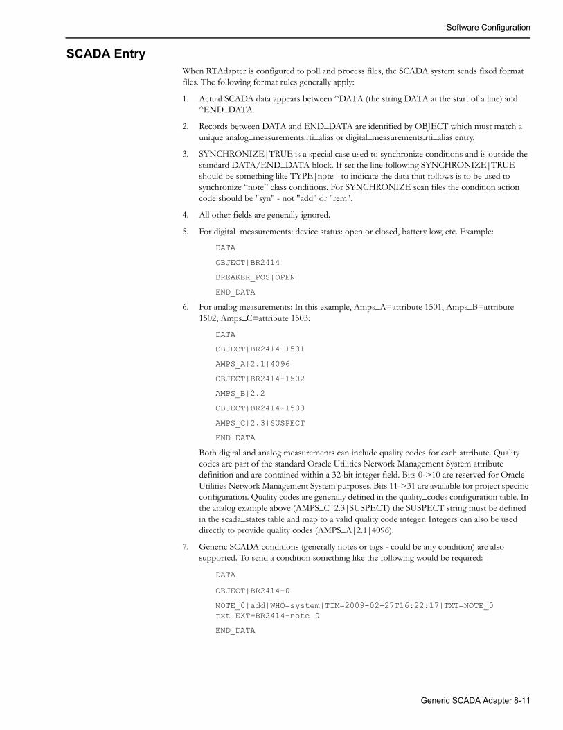
Software Configuration
SCADA EntryWhen RTAdapter is configured to poll and process files, the SCADA system sends fixed format files. The following format rules generally apply:
1. Actual SCADA data appears between ^DATA (the string DATA at the start of a line) and ^END_DATA.
2. Records between DATA and END_DATA are identified by OBJECT which must match a unique analog_measurements.rti_alias or digital_measurements.rti_alias entry.
3. SYNCHRONIZE|TRUE is a special case used to synchronize conditions and is outside the standard DATA/END_DATA block. If set the line following SYNCHRONIZE|TRUE should be something like TYPE|note - to indicate the data that follows is to be used to synchronize “note” class conditions. For SYNCHRONIZE scan files the condition action code should be "syn" - not "add" or "rem".
4. All other fields are generally ignored.
5. For digital_measurements: device status: open or closed, battery low, etc. Example:
DATA
OBJECT|BR2414
BREAKER_POS|OPEN
END_DATA
6. For analog measurements: In this example, Amps_A=attribute 1501, Amps_B=attribute 1502, Amps_C=attribute 1503:
DATA
OBJECT|BR2414-1501
AMPS_A|2.1|4096
OBJECT|BR2414-1502
AMPS_B|2.2
OBJECT|BR2414-1503
AMPS_C|2.3|SUSPECT
END_DATA
Both digital and analog measurements can include quality codes for each attribute. Quality codes are part of the standard Oracle Utilities Network Management System attribute definition and are contained within a 32-bit integer field. Bits 0->10 are reserved for Oracle Utilities Network Management System purposes. Bits 11->31 are available for project specific configuration. Quality codes are generally defined in the quality_codes configuration table. In the analog example above (AMPS_C|2.3|SUSPECT) the SUSPECT string must be defined in the scada_states table and map to a valid quality code integer. Integers can also be used directly to provide quality codes (AMPS_A|2.1|4096).
7. Generic SCADA conditions (generally notes or tags - could be any condition) are also supported. To send a condition something like the following would be required:
DATA
OBJECT|BR2414-0
NOTE_0|add|WHO=system|TIM=2009-02-27T16:22:17|TXT=NOTE_0 txt|EXT=BR2414-note_0
END_DATA
Generic SCADA Adapter 8-11

Software Configuration
The above text would “add” a note condition to the model on the device mapped to BR2414-0. The following keyword phrases can be used to specify common condition fields:
WHO= (who should be recorded as the creator of the condition - must be a valid NMS user name).
TIM= ISO timestamp for when the condition was added. Timestamp format must be defined in your $DATEMSK file.
TXT= Text string for the condition.text field (notes.text. tags.text, etc). Condition text string cannot contain newlines or the separator character - whatever it is configured to be. Text will truncate at the first newline or separator character.
EXT= SCADA unique identifier for the created condition. This field is necessary to allow the external system to later remove the condition.
8. To remote the SCADA condition above:
DATA
OBJECT|BR2414
NOTE_0|rem|WHO=system|TIM=2009-10-27T16:22:17|EXT=BR2414-note_0
END_DATA
For potential use with the NMS MultiSpeak (other Java based) SCADA adapters.
If desired the generic SCADA adapter can be used in conjunction with the NMS MultiSpeak adapter. The intent is use the RTAdapter to provide a buffering mechanism for “noisy” SCADA systems that could potentially generate many periodic analog (or digital) updates. Using RTAdapter to capture and bundle incoming changes reduces the impact on the NMS CORBA Gateway and NMS CORBA publisher – when compared to contacting an internal service directly. Using RTAdapter with the “-dir RDBMS” option allows changes to be captured and sent in bulk to internal NMS Services.
If configured to do so the NMS Web Gateway APIs used by the MultiSpeak SCADA interface will write to the scada_digital_in and scada_analog_in tables when processing updates from an external SCADA. SCADA measurements submitted using Web Gateway APIs 'updateDigitalStatuses' and 'updateMeasurements' can be written into staging tables SCADA_DIGITAL_IN and SCADA_ANALOG_IN instead of being submitted directly to DDService. This behavior is controlled by three configuration properties, which can be added to the CentricityServer.properties file.
1. intersys.use_db_for_scada_statuses
If set to 'true' than device status updates received from SCADA system will be written to the SCADA_DIGITAL_IN database table.
2. intersys.use_db_for_scada_digitals
If set to 'true' than updates to digital values received from SCADA system will be written to the SCADA_DIGITAL_IN database table.
3. intersys.use_db_for_scada_analogs
If set to 'true' than updates to analog values received from SCADA system will be written to the SCADA_ANALOG_IN database table
By default all the above properties are set to 'false', which means that SCADA measurements will be sent directly to the internal DDService process.
8-12 Oracle Utilities Network Management System Adapters Guide
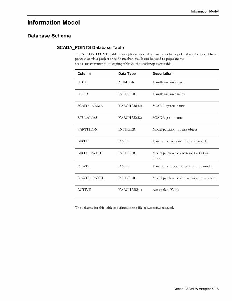
Information Model
Information Model
Database Schema
SCADA_POINTS Database Table
The SCADA_POINTS table is an optional table that can either be populated via the model build process or via a project specific mechanism. It can be used to populate the scada_measurements_st staging table via the scadapop executable.
Column Data Type Description
H_CLS NUMBER Handle instance class.
H_IDX INTEGER Handle instance index
SCADA_NAME VARCHAR(32) SCADA system name
RTU_ALIAS VARCHAR(32) SCADA point name
PARTITION INTEGER Model partition for this object
BIRTH DATE Date object activated into the model.
BIRTH_PATCH INTEGER Model patch which activated with this object.
DEATH DATE Date object de-activated from the model.
DEATH_PATCH INTEGER Model patch which de-activated this object
ACTIVE VARCHAR2(1) Active flag (Y/N)
The schema for this table is defined in the file ces_retain_scada.sql.
Generic SCADA Adapter 8-13

Information Model
SCADA_IDS Database Table
The SCADA_IDS table identifies a specific SCADA name with a numeric ID that is used for RTAdapter (and other) SCADA adapter configuration.
Column Data Type Description
ID NUMBER Numeric identifier for each “scada source” that we want RTI to process.
SCADA_NAME VARCHAR(32) Name for the scada source
ADAPTER_TYPE VARCHAR(32) Adapter type associated with this SCADA. Valid values are ICCP, MULTISPEAK, and RTADAPTER.
ACTIVE VARCHAR(1) ‘Y’/‘N’ - adapter is active or not.
The script, OPAL_scada.sql, populates generic SCADA sources for the OPAL model. A source is any SCADA system that can provide information to the adapter. There could be one SCADA source defined for each of multiple SCADA vendors, or a utility may choose to divide their territory into multiple regions, with each region acting as a separate SCADA source. Each SCADA source must have a name as well as a unique integer ID.
SCADA_SYNONYMS Database Table
The SCADA_SYNONYMS table contains all the synonyms for attribute name or values (e.g., KV_3, AMP_A, and CLOSE) used by RTAdapter in processing flat files of SCADA data input.
Column Data Type Description
id INTEGER Unique integer - primary key.
scada_id INTEGERNOT NULL
Matches scada_ids.id
keyword VARCHAR2(32)NOT NULL
SCADA unique attribute keyword string from SCADA system. Generally maps to an NMS attribute name but this is not required unless the scada_synonyms.attribute_alias field is left blank.If the scada_synonyms.attribute_alias field is left blank than the scada_synonyms.keyword field must map to a valid attribute name - from attributes.name (table.column).For conditions this is unique name used by external SCADA to identify the condition class (NOTE, TAG, etc). NMS condition class must be defined in scada_synonyms.attribute_alias.
value VARCHAR2(32) For digitals: Customer value associated with keyword that indicates digital state (OPEN, CLOSED).For analogs: This field can be null.For conditions: Must be “add”, “rem” or “syn”. The “syn” value is used for synchronization requests.
8-14 Oracle Utilities Network Management System Adapters Guide
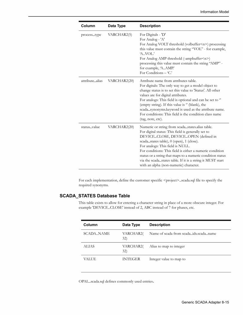
Information Model
For each implementation, define the customer specific <project>_scada.sql file to specify the required synonyms.
SCADA_STATES Database Table
This table exists to allow for entering a character string in place of a more obscure integer. For example 'DEVICE_CLOSE' instead of 2, ABC instead of 7 for phases, etc.
Column Data Type Description
SCADA_NAME VARCHAR2(32)
Name of scada from scada_ids.scada_name
ALIAS VARCHAR2(32)
Alias to map to integer
VALUE INTEGER Integer value to map to
OPAL_scada.sql defines commonly used entries.
process_type VARCHAR2(5) For Digitals - 'D'For Analog - 'A'For Analog VOLT threshold (volbuffer<n>) processing this value must contain the string “VOL” - for example, ‘A_VOL.’ For Analog AMP threshold (-ampbuffer<n>) processing this value must contain the string “AMP” - for example, ‘A_AMP.’For Conditions – ‘C.’
attribute_alias VARCHAR2(20) Attribute name from attributes table.For digitals: The only way to get a model object to change status is to set this value to 'Status'. All other values are for digital attributes.For analogs: This field is optional and can be set to ‘’ (empty string). If this value is ‘’ (blank), the scada_synonyms.keyword is used as the attribute name.For conditions: This field is the condition class name (tag, note, etc).
status_value VARCHAR2(20) Numeric or string from scada_states.alias table.For digital status: This field is generally set to DEVICE_CLOSE, DEVICE_OPEN (defined in scada_states table), 0 (open), 1 (close).For analogs: This field is NULL.For conditions: This field is either a numeric condition status or a string that maps to a numeric condition status via the scada_states table. If it is a string it MUST start with an alpha (non-numeric) character.
Column Data Type Description
Generic SCADA Adapter 8-15

Information Model
SCADA_DIGITAL_IN Database Table
The scada_digital_in table can be used by RTAdapter to queue incoming digital SCADA updates. RTAdapter, if configured to do so, will periodically poll this table and check for unprocessed rows (status='N'). If unprocessed rows are found, RTAdapter will attempt to update the model according to data provided. Note that the database sequence scada_digital_in_sequence must be set up properly to create the primary key (scada_digital_in.id) value on insert.
If the -retain option is not used, records are always deleted after they are processed and the only record of any failure is in the RTAdapter log itself. It is generally recommended that production systems run this way (i.e., without the -retain option).
If the -retain option is used all rows are retained in the SCADA_DIGITAL_IN table. Processed records have scada_digital_in.status column set to "S" after they are processed. If an error occurs the scada_digital_in.status column will be set to 'E', and the scada_digital_in.error_code and scada_digital_in.error_description columns should be populated with some indication of the problem.
Note that use of the -retain option is not generally intended as a production option; rather it is a temporary mechanism to help validate/test the interface. With the -retain option, a busy (noisy) SCADA system can cause the scada_digital_in table to grow without bound. This (size of the scada_digital_in table) must in turn be managed by the customer, which creates a maintenance issue.
If scada_digital_in.attribute is a numeric, it must match a valid NMS attribute number (for example, 0 is topology status). If non-numeric, both the scada_digital_in.attribute and scada_digital_in.operation values must be properly defined in the scada_synonyms and scada_states tables.
One of three methods can be used to identify a specific NMS attribute measurement.
1. If the rti_alias values in the digital_measurements table uniquely identify each measurement you do not need to specify an attribute on input. This is the preferred way to operate. If the project can support operating in this manner suggest adding a unique index on digital_measurements.rti_alias to enforce this.
2. If the digital_measurements.rti_alias column is NOT unique a unique combination of digital_measurements.rti_alias and digital_measurements.attribute must provided for each record in the scada_analog_in table (the combination must be unique). If a valid rti_alias is provided but no valid handle is available you must set h_cls=0 and h_idx=0. This tells RTAdapter which scheme to use to find the appropriate digital to update. Since this scheme requires the external SCADA system to identify which NMS attribute each measurement is for it is generally deemed less desirable than option 1 above.
3. A valid NMS handle AND attribute number - in this case the alias can be left blank. This is not often used as it requires the external system to know NMS handles and attribute numbers.
Column Data Type Description
ID VARCHAR2(32) scada_digital_in sequence generated pk
H_CLS NUMBER(38,0) NMS class of device – can be null if alias is not null.
H_IDX NUMBER(38,0) NMS index of device – can be null if alias is not null.
8-16 Oracle Utilities Network Management System Adapters Guide

Information Model
ALIAS VARCHAR2(128) SCADA point alias - can be null if h_cls and h_idx are NOT null. If not null it is suggested this value (alone) uniquely identify a measurement.
ATTRIBUTE VARCHAR(32) SCADA attribute. If numeric, it must match a valid NMS attribute number. If it is a string, it must map to a valid NMS attribute number via the scada_synonyms table. If the ALIAS above is unique it is NOT necessary to include an attribute value on input.
PHASES VARCHAR(4) Intended phases for operation. If numeric must be between 1 and 7 – where 1 is A and 7 is ABC. If a string must map to a valid numeric via the scada_states table.
OPERATION VARCHAR(32) Operation. If numeric and used for attribute 0 (topology status) it must be 1(open) or 1(close) and the phase attribute must be set to indicate which phases are intended to operate. If a string it must map to a valid code for the attribute involved via a combination of the scada_synonyms table and/or the scada_states table.
OPERATION_DATE DATE Time the operation occurred in the field. If left blank will default to SYSDATE.
OPERATION_COUNT NUMBER(10) How many operations have occurred since the last scan – for momentaries (not presently supported).
CAPTURE_DATE DATE When operation captured by NMS - generally set to SYSDATE.
QUALITY VARCHAR2(32) Quality code for attribute – can be numeric or a string. Either way it must be properly configured in NMS and must ultimately translate to be greater than 0x7FF (2047) and less than or equal to 0xFFFF. All quality codes below 0x7FF are reserved for NMS.
SOURCE VARCHAR(32) Data source/user name
STATUS VARCHAR2(1) Status of request:N = NewE = Error
Column Data Type Description
Generic SCADA Adapter 8-17
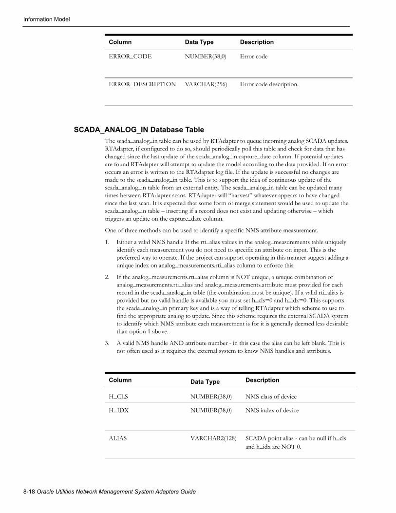
Information Model
SCADA_ANALOG_IN Database Table
The scada_analog_in table can be used by RTAdapter to queue incoming analog SCADA updates. RTAdapter, if configured to do so, should periodically poll this table and check for data that has changed since the last update of the scada_analog_in.capture_date column. If potential updates are found RTAdapter will attempt to update the model according to the data provided. If an error occurs an error is written to the RTAdapter log file. If the update is successful no changes are made to the scada_analog_in table. This is to support the idea of continuous update of the scada_analog_in table from an external entity. The scada_analog_in table can be updated many times between RTAdapter scans. RTAdapter will “harvest” whatever appears to have changed since the last scan. It is expected that some form of merge statement would be used to update the scada_analog_in table – inserting if a record does not exist and updating otherwise – which triggers an update on the capture_date column.
One of three methods can be used to identify a specific NMS attribute measurement.
1. Either a valid NMS handle If the rti_alias values in the analog_measurements table uniquely identify each measurement you do not need to specific an attribute on input. This is the preferred way to operate. If the project can support operating in this manner suggest adding a unique index on analog_measurements.rti_alias column to enforce this.
2. If the analog_measurements.rti_alias column is NOT unique, a unique combination of analog_measurements.rti_alias and analog_measurements.attribute must provided for each record in the scada_analog_in table (the combination must be unique). If a valid rti_alias is provided but no valid handle is available you must set h_cls=0 and h_idx=0. This supports the scada_analog_in primary key and is a way of telling RTAdapter which scheme to use to find the appropriate analog to update. Since this scheme requires the external SCADA system to identify which NMS attribute each measurement is for it is generally deemed less desirable than option 1 above.
3. A valid NMS handle AND attribute number - in this case the alias can be left blank. This is not often used as it requires the external system to know NMS handles and attributes.
ERROR_CODE NUMBER(38,0) Error code
ERROR_DESCRIPTION VARCHAR(256) Error code description.
Column Data Type Description
Column Data Type Description
H_CLS NUMBER(38,0) NMS class of device
H_IDX NUMBER(38,0) NMS index of device
ALIAS VARCHAR2(128) SCADA point alias - can be null if h_cls and h_idx are NOT 0.
8-18 Oracle Utilities Network Management System Adapters Guide

Information Model
SCADA_MEASUREMENTS_ST Database Table
SCADA_MEASUREMENTS_ST is a staging table used to capture relevant information for each measurement attribute. It can be populated via the scadapop executable (discussed previously in this document) or via project specific means. It can be completely rebuilt at will as it is NOT a run-time table. The “updateDDS -recacheMeasures” utility sends a message to DDService to merge measurements defined in this table with the run-time analog_measurements and digital_measurements tables.
ATTRIBUTE VARCHAR(16) SCADA attribute. If it is numeric it must match a valid NMS attribute. If it is a string it must be defined in scada_synonyms and map to a valid NMS attribute. If it is NOT provided the provided ALIAS must be provided and MUST uniquely identify a measurement.
MEASUREMENT NUMBER Analog update value.
MEASUREMENT_DATE DATE When operation occurred in field – not presently used.
CAPTURE_DATE DATE When measurement captured – could be updated by trigger on table update. This is the how RTAdapter determines what to examine during periodic polls.
QUALITY VARCHAR2(32) Quality code for attribute – can be numeric or a string. Either way it must be properly configured in NMS and must ultimately translate to be greater than 0x7FF (2047) and less than or equal to 0xFFFF. All quality codes below 0x7FF are reserved for NMS.
SOURCE VARCHAR(32) source/user name
Column Data Type Description
Column Data Type Description
H_CLS NUMBER Object handle
H_IDX NUMBER Object index
PARTITION NUMBER Object partition handle
Generic SCADA Adapter 8-19
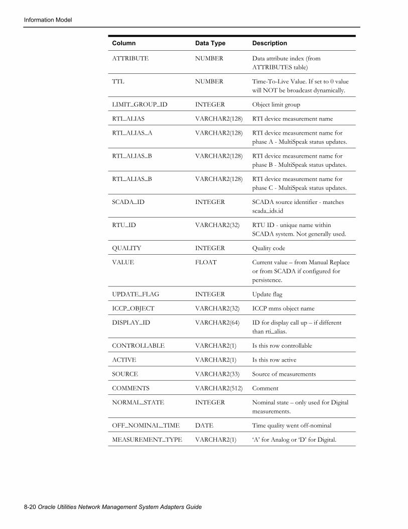
Information Model
ATTRIBUTE NUMBER Data attribute index (from ATTRIBUTES table)
TTL NUMBER Time-To-Live Value. If set to 0 value will NOT be broadcast dynamically.
LIMIT_GROUP_ID INTEGER Object limit group
RTI_ALIAS VARCHAR2(128) RTI device measurement name
RTI_ALIAS_A VARCHAR2(128) RTI device measurement name for phase A - MultiSpeak status updates.
RTI_ALIAS_B VARCHAR2(128) RTI device measurement name for phase B - MultiSpeak status updates.
RTI_ALIAS_B VARCHAR2(128) RTI device measurement name for phase C - MultiSpeak status updates.
SCADA_ID INTEGER SCADA source identifier - matches scada_ids.id
RTU_ID VARCHAR2(32) RTU ID - unique name within SCADA system. Not generally used.
QUALITY INTEGER Quality code
VALUE FLOAT Current value – from Manual Replace or from SCADA if configured for persistence.
UPDATE_FLAG INTEGER Update flag
ICCP_OBJECT VARCHAR2(32) ICCP mms object name
DISPLAY_ID VARCHAR2(64) ID for display call up – if different than rti_alias.
CONTROLLABLE VARCHAR2(1) Is this row controllable
ACTIVE VARCHAR2(1) Is this row active
SOURCE VARCHAR2(33) Source of measurements
COMMENTS VARCHAR2(512) Comment
NORMAL_STATE INTEGER Nominal state – only used for Digital measurements.
OFF_NOMINAL_TIME DATE Time quality went off-nominal
MEASUREMENT_TYPE VARCHAR2(1) ‘A’ for Analog or ‘D’ for Digital.
Column Data Type Description
8-20 Oracle Utilities Network Management System Adapters Guide
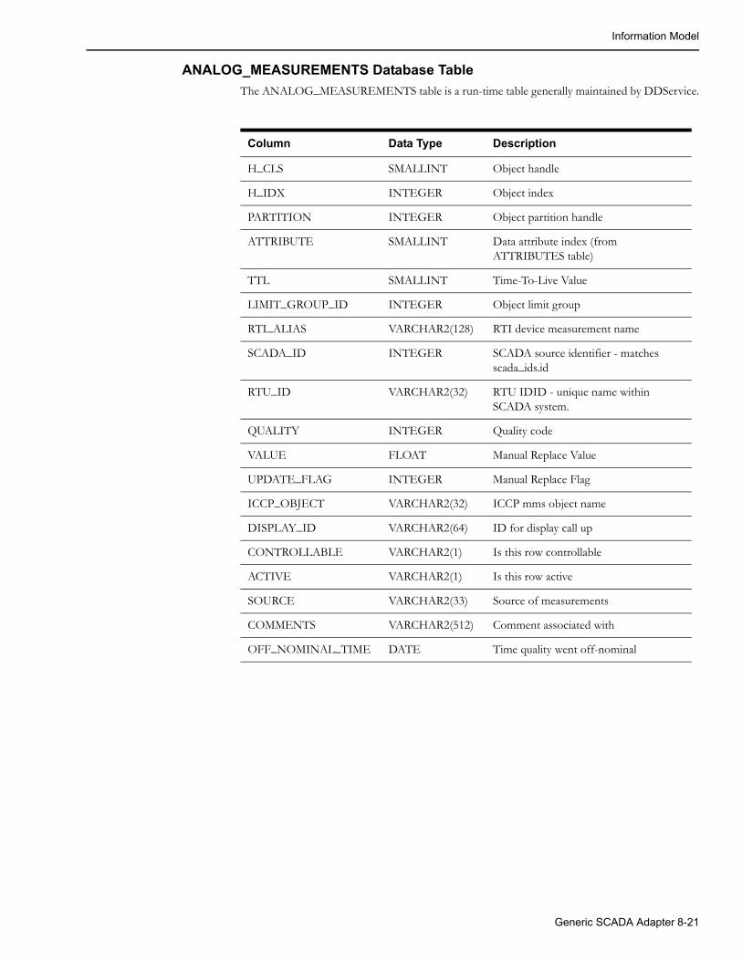
Information Model
ANALOG_MEASUREMENTS Database Table
The ANALOG_MEASUREMENTS table is a run-time table generally maintained by DDService.
Column Data Type Description
H_CLS SMALLINT Object handle
H_IDX INTEGER Object index
PARTITION INTEGER Object partition handle
ATTRIBUTE SMALLINT Data attribute index (from ATTRIBUTES table)
TTL SMALLINT Time-To-Live Value
LIMIT_GROUP_ID INTEGER Object limit group
RTI_ALIAS VARCHAR2(128) RTI device measurement name
SCADA_ID INTEGER SCADA source identifier - matches scada_ids.id
RTU_ID VARCHAR2(32) RTU IDID - unique name within SCADA system.
QUALITY INTEGER Quality code
VALUE FLOAT Manual Replace Value
UPDATE_FLAG INTEGER Manual Replace Flag
ICCP_OBJECT VARCHAR2(32) ICCP mms object name
DISPLAY_ID VARCHAR2(64) ID for display call up
CONTROLLABLE VARCHAR2(1) Is this row controllable
ACTIVE VARCHAR2(1) Is this row active
SOURCE VARCHAR2(33) Source of measurements
COMMENTS VARCHAR2(512) Comment associated with
OFF_NOMINAL_TIME DATE Time quality went off-nominal
Generic SCADA Adapter 8-21

Information Model
DIGITAL_MEASUREMENTS Database Table
The DIGITAL_MEASUREMENTS table is a run-time table generally maintained by DDService.
Column Data Type Description
H_CLS SMALLINT Object handle
H_IDX INTEGER Object index
PARTITION INTEGER Object partition handle
ATTRIBUTE SMALLINT Data attribute index (from ATTRIBUTES table)
TTL SMALLINT Time-To-Live Value
LIMIT_GROUP_ID INTEGER Object limit group
RTI_ALIAS VARCHAR2(128) RTI device measurement name
SCADA_ID INTEGER SCADA source identifier
RTU_ID VARCHAR2(32) RTU ID
QUALITY INTEGER Quality code
VALUE FLOAT Manual Replace Value
UPDATE_FLAG INTEGER Manual Replace Flag
ICCP_OBJECT VARCHAR2(32) ICCP mms object name
DISPLAY_ID VARCHAR2(64) ID for display call up
NORMAL_STATE INTEGER Normal state for measure
CONTROLLABLE VARCHAR2(1) Is this row controllable
ACTIVE VARCHAR2(1) Is this row active
SOURCE VARCHAR2(33) Source of measurements
COMMENTS VARCHAR2(512) Comment associated with
OFF_NOMINAL_TIME DATE Time quality went off-nominal
This section provides an overview of the logical information model supported by this interface. The key objects supported by this interface include:
• Customers, which are defined using accounts, service locations and meters. This model is based upon the MultiSpeak model. Typically, as a practical note, the custId identifier may in fact be the same as the account number. Some extensions to the MultiSpeak model are used as required to address issues that are otherwise not addressed by MultiSpeak. The support of a bulk load process that reads a XML file, with defined customers to create the model. This process (createSql) can be ran to generate the SQL to be run on the production servers, or can directly create the customers.
• Trouble calls are also referred to as incidents within Oracle Utilities Network Management System. An incident is typically related to a customer, who in turn is related to a device. In the absence of a correlation to a device, a trouble call is classified as a ‘fuzzy’ call, which
8-22 Oracle Utilities Network Management System Adapters Guide

Information Model
differentiates it from a call that can be directly correlated to the electrical distribution network.
• Outages, which are a consequence of the correlation of incidents. Outages are one form of an event that is managed by JMService. Some events are non-outage events, such as power quality. The type of call that is provided can identify such non-outage and outage events. Each call needs to be identified with a trouble code, which will determine the type of call that JMService will generate with in Oracle Utilities Network Management System.
• Devices, which are part of the electrical distribution network. Customers, outages and conditions may have relationships to devices. Typically customers are related to transformer devices. Outages are typically related to switch, fuse or transformer devices.
• Conditions (which can be specialized within Oracle Utilities Network Management System for the management of information such as tags, notes, etc.)
• SQL queries, result sets and transactions.
• Customer disconnections and reconnections for indicating customers who have been purposely removed from Service by the utility.
• Crew Outage States that will identify outage states that change as a result of a crew action. For example a crew that has been dispatched, assigned, or suspended from outage work would correlate to an action that may trigger an outage state change in Oracle Utilities Network Management System.
The information described by these models is formatted using XML for the purposes of exchange through this interface. The following table describes tags that are used in the XML definitions, and how they relate to the information model within Oracle Utilities Network Management System. The corresponding types used in these models are I = Integer, S = String, T = TimeStamp, C = Single Character, and F = floating point.
Generic SCADA Adapter 8-23

Information Model
8-24 Oracle Utilities Network Management System Adapters Guide
Chapter 9ICCP Adapter
This chapter includes the following topics:
• ICCP Adapter Overview
• LiveData ICCP Adapter Configuration
• TMW ICCP Adapter Configuration
ICCP Adapter Overview The Oracle Utilities Network Management System ICCP Adapter integrates the Oracle Utilities Network Management System with a remote SCADA system through the Inter-control Center Communications Protocol (ICCP). Oracle offers two versions of an ICCP adapter. One Oracle ICCP adapter (TMW ICCP Adapter) uses ICCP libraries from Triangle MicroWorks (TMW) and can interface directly to a 3rd-party SCADA system that supports the ICCP protocol. The other Oracle ICCP adapter (LiveData ICCP Adapter) does not directly speak ICCP, but instead interfaces to a LiveData 3rd-party ICCP server using LiveData proprietary APIs, which then interfaces to the SCADA system that supports the ICCP protocol.
Note: TMW ICCP Adapter includes the TWM libraries bundled in. The LiveData ICCP Adapter requires the use of a LiveData Server that must be separately licensed from LiveData, Inc. For additional details on the LiveData Server, please refer to LiveData documentation.
ICCP is a standard interface protocol that can be used with Oracle Utilities Network Management System to provide data exchange with remote and local SCADA systems. ICCP is also an international standard: International Electrotechnical Commission (IEC) Telecontrol Application Service Element 2 (TASE.2).
ICCP allows the exchange of real-time and historical power system monitoring and control data, including measured values, scheduling data, energy accounting data, and operator messages. Data exchange can occur between:
• Multiple control center Energy Management System (EMS) systems
• EMS and power plant DCS systems
• EMS and distribution SCADA systems
• EMS and other utility systems
• EMS/SCADA and substations
ICCP Adapter 9-1

ICCP Adapter Overview
The ICCP standard consists of the following blocks:
Block Description Notes
Block 1 Basic Services Available via both the Oracle TMW ICCP Adapter and the Oracle LiveData ICCP Adapter.
Block 2 Extended Data Set Condition Monitoring Available via both the Oracle TMW ICCP Adapter and the Oracle LiveData ICCP Adapter.
Block 3 Blocked Transfers
Block 4 Operator Stations
Block 5 Device Control Currently only available via the Oracle LiveData ICCP Adapter.
Block 6 Programs
Block 7 Events
Block 8 Accounts
Block 9 Time Series
9-2 Oracle Utilities Network Management System Adapters Guide
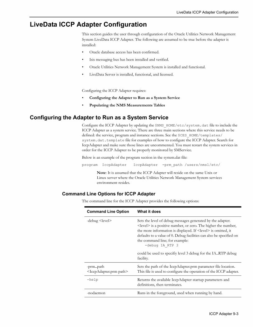
LiveData ICCP Adapter Configuration
LiveData ICCP Adapter ConfigurationThis section guides the user through configuration of the Oracle Utilities Network Management System LiveData ICCP Adapter. The following are assumed to be true before the adapter is installed:
• Oracle database access has been confirmed.
• Isis messaging bus has been installed and verified.
• Oracle Utilities Network Management System is installed and functional.
• LiveData Server is installed, functional, and licensed.
Configuring the ICCP Adapter requires:
• Configuring the Adapter to Run as a System Service
• Populating the NMS Measurements Tables
Configuring the Adapter to Run as a System ServiceConfigure the ICCP Adapter by updating the $NMS_HOME/etc/system.dat file to include the ICCP Adapter as a system service. There are three main sections where this service needs to be defined: the service, program and instance sections. See the $CES_HOME/templates/system.dat.template file for examples of how to configure the ICCP Adapter. Search for IccpAdapter and make sure those lines are uncommented. You must restart the system services in order for the ICCP Adapter to be properly monitored by SMService.
Below is an example of the program section in the system.dat file:
program IccpAdapter IccpAdapter -prm_path /users/nms1/etc/
Note: It is assumed that the ICCP Adapter will reside on the same Unix or Linux server where the Oracle Utilities Network Management System services environment resides.
Command Line Options for ICCP Adapter
The command line for the ICCP Adapter provides the following options:
Command Line Option What it does
-debug <level> Sets the level of debug messages generated by the adapter. <level> is a positive number, or zero. The higher the number, the more information is displayed. If <level> is omitted, it defaults to a value of 0. Debug facilities can also be specified on the command line; for example:
could be used to specifiy level 3 debug for the IA_RTP debug facility.
-prm_path <IccpAdapter.prm path>
Sets the path of the IccpAdapter.prm parameter file location. This file is used to configure the operation of the ICCP adapter.
-help Returns the available IccpAdapter startup parameters and definitions, then terminates.
-nodaemon Runs in the foreground, used when running by hand.
-debug IA_RTP 3
ICCP Adapter 9-3

LiveData ICCP Adapter Configuration
IccpAdapter.prm
The IccpAdapter.prm file is used to configure the operation of the Oracle Utilities Network Management System ICCP Adapter. The default location for this file is the same as where the IccpAdapter binary is located (i.e., $CES_HOME/bin) but it is generally configured to be in a different location by using the –prm_path <IccpAdapter.prm path> command line option. Lines in this file beginning with a “;” (semi-colon) are comments. Lines beginning with a “[” (left bracket) are block identifiers (markers). Fields marked as <Required> must be configured for proper operation and are generally site specific. See the IccpAdapter.prm.template file in the standard $CES_HOME/templates directory for an example IccpAdapter configuration file.
Fields in the IccpAdapter.prm File
Field name Type Default Valid Values Description
[IccpAdapter] Marker Used for generic configuration of program.
ServerHostname IP addressList – blankseparated
<Required> 128.168.148.43 etc
The IP address(es) of the LiveData Server hostname(s) to connect to. It could be a blank separated list of IP address of several LiveData Servers. In case a failure of connection was detected by the ICCP Adapter with the current LiveData Server, it will traverse the ServerHostname list for the next LiveData Server to connect to.
Port Integer <Required> [1..MAX_INT] Blank separated list of TCP/IP port numbers that the ICCP Adapter will use for a connection attempt to a LiveData Server. Parallel to the ServerHostname, it could be a list of port numbers to use to connect to the corresponding LiveData server in ServerHostname. In case there was a failure of connection with the current LiveData Server, it would proceed to the next entry - in parallel with the next ServerHostname entry. 5002 is typical.
Period Integer 10 [1..MAX_INT] Time in seconds between periodic transfers of non-time critical data.
StatusUpdates Integer 25 [1..MAX_INT] The maximum number of status updates to be sent to DDService at one time.
ScadaId Integer 1 [1..MAX_INT] Identification number assigned to the SCADA in Oracle Utilities Network Management System with which the ICCP Adapter is communicating.
AnalogTolerance Double 0.0F [0.01..0.99] Dead band for analog value updates. It is the required percent change from the last reported value to trigger an update.
Analogs Boolean F [T, F] Boolean value indicating use of the ANALOG_MEASUREMENTS table.
Digitals Boolean T [T, F] Boolean value indicating use of the DIGITAL_MEASUREMENTS table.
9-4 Oracle Utilities Network Management System Adapters Guide

LiveData ICCP Adapter Configuration
ReconnectPeriod Integer 60 [0..MAX_INT] Configurable duration of delay to wait after the LiveData Server instances failed in succession.
Controls Boolean F [T, F] Boolean value indicating use of the controls table for Block 5 functionality.
QualityCodeUseOnAssociationTimeOut
Integer 0 [0..MAX_INT] Quality code that will be sent to DDService when the communication with LD server is lost. A valid QualityCode must be specified if this option is used.
DisableStop Boolean F [T, F] Normally the adapter will accept and process a stop high level message. This option disables this feature. When this feature is enabled, the adapter will disregard a stop high level message.
DisableCOV Boolean F [T, F] Normally the adapter will process a COV update (one or more open and close sequences within a scan cycle – normally indicating one or more momentaries) and send it to DDService. This option disables this feature.
Vccs Integer <Required> [1..MAX_INT] The number of VCCs (Virtual Control Centers) that are configured in the LiveData Server.
IgnoreCritInterSysServFail Boolean F [T, F] Normally the adapter will stop if SMSserivce reports a critical service failure and not restart until services are recovered. This option disables this feature.
NoSwitchOpQualityMask Integer No Mask [0..MAX_INT] This parameter sets the quality codes that prevent switches from being operated. There is no effect on non-switch statuses.
PhaseEncodeSwitch Boolean F [T, F] If set to true, this will enable Iccp Adapter to interpret data discrete values as three-bit phase encoded statuses. [e.g., A = ‘001’, B = ‘010’, C = ‘100’, etc.]
PseudoAlarms Boolean F [T, F] If set to 1, then this will set the pseudo flag for the switch entry to be sent to DDService. Generates pseudo (advisory) alarms for ICCP reported device ops rather than actually operating the switches in the Oracle Utilities Network Management System model.
SendTimeout Integer 10 [0..MAX_INT] Number of seconds to wait when attempting to connect ICCP Adapter to the LiveData server. If no connection is received, it will move to the next available LiveData server (if configured). Generally leave as the default.
Field name Type Default Valid Values Description
ICCP Adapter 9-5

LiveData ICCP Adapter Configuration
DetachRead Boolean T [T,F] Detach the IccpAdapter internal thread that is reading the incoming RTP data stream from Isis. Generally leave as the default.
DetachWrite Boolean F [T,F] Detach the IccpAdapter internal thread that is writing the outgoing RTP data stream from Isis. Generally leave as the default
DetachHeartbeat Boolean F [T,F] Detach the IccpAdapter internal thread that is sending outgoing RTP data stream heartbeat requests from Isis. Generally leave as the default
[VCC#] Marker E.g., [VCC1]. Provides additional information for each VCC (Virtual Control Center).
AssociationAddress Integer <Required> [1..MAX_INT] RTP address in LiveData Server for watching and controlling this VCCs association status
TransferSetAddress Integer <Required> [1..MAX_INT] RTP address in LiveData Server for controlling the use of configured ICCP transfer sets
NumTransferSets Integer <Required> [1..MAX_INT] The total number of transfer sets that are available for use in the VCC. Number must be a multiple of 16.
AssociationName String Vcc Label [a..z, A..Z, 0..9] The name of the ICCP Association.
AssociationRestartTime Integer 30 [1..MAX_INT] Seconds allowed for restart before the association is considered failed.
TransferSetRestartPeriod Integer 30 [1..MAX_INT] Seconds allowed to restart transferset before the restart is considered failed and no additional restart attempts will be made.
TransferSetFailCountReset Integer 60 [1..MAX_INT] The number of fail count to be exhausted before marking the transfer set as not alive.
MaxTransferSetRestarts Integer 10 [1..MAX_INT] Maximum number of restart for transfer set.
TransferSetControlMask String <Required> [T, F] Transfer set control mask for the transfer set to be sent to LiveData Server. One T/F flag for each TransferSet. String length must be a multiple of 16.Example with one TransferSet enabled: "FTTTTTTTTTTTTTTT"
Field name Type Default Valid Values Description
9-6 Oracle Utilities Network Management System Adapters Guide

LiveData ICCP Adapter Configuration
[ValidityQuality] Marker Assign an Oracle Utilities Network Management System quality to ICCP Validity Quality values
Valid Integer 0 2**n (n=11->31) The value is valid. This is the default (normal) value should virtually always be 0.
Held Integer 0 2**n (n=11->31) Previous data value has been held over. Interpretation is local.
Suspect Integer 0 2**n (n=11->31) Data value is questionable. Interpretation is local.
Notvalid Integer 0 2**n (n=11->31) The value is not valid.
[CurrentSourceQuality] Marker Assign an Oracle Utilities Network Management System quality to ICCP Current Source Quality values.
Telemetered Integer 0 2**n (n=11->31) Value was received from a telemetered site. This is the default (normal) value should virtually always be 0.
Calculated Integer 0 2**n (n=11->31) Value was calculated based on other data.
Entered Integer 0 2**n (n=11->31) Value was entered manually.
Estimated Integer 0 2**n (n=11->31) Value was estimated (State Estimator, etc.).
[NormalValueQuality] Marker Assign an Oracle Utilities Network Management System quality to ICCP Normal Value Quality values.
Normal Integer 0 2**n (n=11->31) The point value is that which has been configured as normal for the point. This is the default (normal) value should virtually always be 0.
Abnormal Integer 0 2**n (n=11->31) The point value is not that which has been configured as normal for the point.
[TimeStampQuality] Marker Assign an Oracle Utilities Network Management System quality to ICCP Timestamp Quality values
Valid Integer 0 2**n (n=11->31) Current value of the TimeStamp attribute contains the time stamp of when the value was last changed. This is the default (normal) value should virtually always be 0.
Invalid Integer 0 2**n (n=1->31) Current value of the TimeStamp attribute contains the time stamp other than when the value was last changed.
[SwitchStatusQuality] Marker Assign an Oracle Utilties Network Management System quality to the non-open/close statuses that can be returned in the two-bit ICCP status field. ICCP “open” is generally (1) and “closed” is (2).
Field name Type Default Valid Values Description
ICCP Adapter 9-7
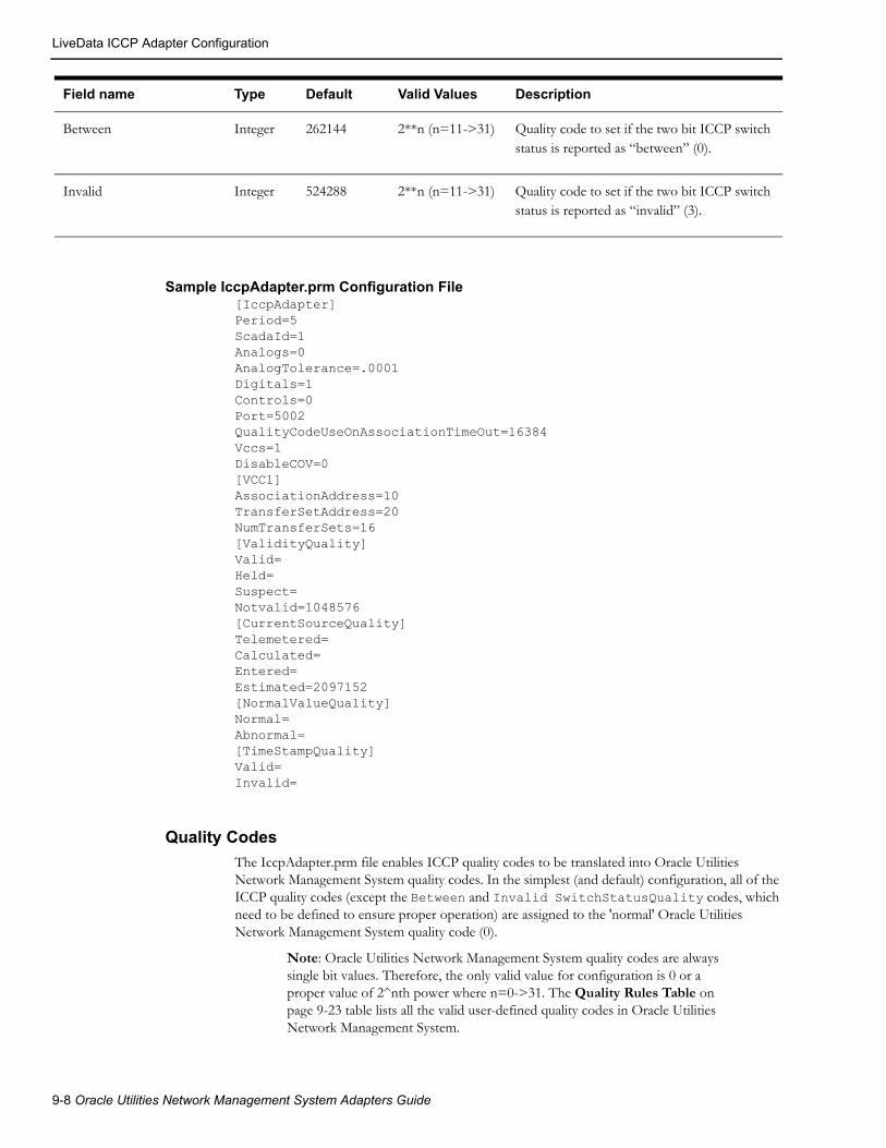
LiveData ICCP Adapter Configuration
Sample IccpAdapter.prm Configuration File[IccpAdapter]Period=5ScadaId=1Analogs=0AnalogTolerance=.0001Digitals=1Controls=0Port=5002QualityCodeUseOnAssociationTimeOut=16384Vccs=1DisableCOV=0[VCC1]AssociationAddress=10TransferSetAddress=20NumTransferSets=16[ValidityQuality]Valid=Held=Suspect=Notvalid=1048576[CurrentSourceQuality]Telemetered=Calculated=Entered=Estimated=2097152[NormalValueQuality]Normal=Abnormal=[TimeStampQuality]Valid=Invalid=
Quality Codes
The IccpAdapter.prm file enables ICCP quality codes to be translated into Oracle Utilities Network Management System quality codes. In the simplest (and default) configuration, all of the ICCP quality codes (except the Between and Invalid SwitchStatusQuality codes, which need to be defined to ensure proper operation) are assigned to the 'normal' Oracle Utilities Network Management System quality code (0).
Note: Oracle Utilities Network Management System quality codes are always single bit values. Therefore, the only valid value for configuration is 0 or a proper value of 2^nth power where n=0->31. The Quality Rules Table on page 9-23 table lists all the valid user-defined quality codes in Oracle Utilities Network Management System.
Between Integer 262144 2**n (n=11->31) Quality code to set if the two bit ICCP switch status is reported as “between” (0).
Invalid Integer 524288 2**n (n=11->31) Quality code to set if the two bit ICCP switch status is reported as “invalid” (3).
Field name Type Default Valid Values Description
9-8 Oracle Utilities Network Management System Adapters Guide
LiveData ICCP Adapter Configuration
If none of the predefined quality codes are applicable, then a new code must be created. The following steps accomplish this:
• Choose an ICCP quality listed in the IccpAdapter.prm.
• Check the Quality Rules Table to see which values have already been assigned to qualities.
• Assign one of the values listed below to the ICCP quality and enter it in the Quality Rules Table.
• Locate the quality in the IccpAdapter.prm file and enter the assigned value for it.
The assigned value must be the decimal representation of 32 bits, where no more than one bit has a value of 1. For example, if the bit position is 11, use the number 2048. The following list contains the decimal values that may be assigned to new qualities: 2048, 4096, 8192, 16384, 32768, 65536, 131072, 262144, 524288, 1048576, 2097152, 4194304, 8388608, 16777216, 33554432, 67108864, 134217728, 268435456, 536870912, 1073741824, 2147483648.
Values of 0, 1, 2, 4, 8, 16, 32, 64, 128, 256, 512, 1024 may not be assigned as codes for new qualities because they are already defined and used within Oracle Utilities Network Management System. The ‘normal’ Oracle Utilities Network Management System quality code is 0.
The adapter reads the IccpAdapter.prm file only during startup. If the quality code is added when the adapter is running, you must restart the adapter in order for it to recognize the new quality code.
High Level Messages
The ICCP Adapter can be dynamically controlled from Oracle Utilities Network Management System by using high-level messages. They can be used any time while running the Oracle Utilities Network Management System ICCP Adapter. The following high-level messages can be used:
• stop
Disconnect from the LiveData Server and stop the Oracle Utilities Network Management System ICCP Adapter.
• report
Empty message to determine how many Oracle Utilities Network Management System ICCP Adapters are running.
• debug [on | off | #]
Turn on/off debug, or set it to a specific level. On is equivalent to 1, off is 0. Level can be any integer value no less than 0.
• debug <facility> #
Turn facility specific debug on/off. For example, to turn IA_RTP debug on to level 3:
Action any.IccpAdapter debug IA_RTP 3
To turn off:
Action any.IccpAdapter debug IA_RTP 0
Check ICCP Adapter specific log file for other facilities specific to this adapter process.
• demote
Causes the Oracle Utilities Network Management System ICCP Adapter currently in control to relinquish control.
Use IccpAdapterService with high-level messages for the Oracle Utilities Network Management System ICCP Adapter. For example:
Action any.IccpAdapter report
ICCP Adapter 9-9

LiveData ICCP Adapter Configuration
Populating the NMS Measurements TablesICCP points must first be mapped to devices in the Oracle Utilities Network Management System model before sending SCADA updates to Oracle Utilities Network Management System. These ICCP points are placed in SCADA Measurements table of the Oracle Utilities Network Management System database. A process needs to be formalized to create and maintain this data. This process often depends on customer specific mechanisms used to maintain the SCADA side of the ICCP interface. As a result this process generally needs to be formalized by LiveData and the customer - potentially with help from NMS consulting.
Required NMS Data from LiveData
The following data items are required to be populated in the NMS measurements tables:
• ICCP Name
• ICCP Type
• Attribute
• NMSDeviceID
ICCP Name• ICCP Name has to be unique.
• It is recommended for the name to be composed of alpha-numeric characters and underscore
• It is recommended for the first character of the ICCP Name to be a letter
• There should be no space, no periods and no dashes in the ICCP name.
ICCP TypeBelow is a list of supported ICCP Types. Please take note of the underscore.
• Data_State
• Data_StateQ
• Data_StateQTimeTag
• Data_StateExtended
• Data_Real
• Data_RealQ
• Data_RealQTimeTag
• Data_RealExtended
• Data_Discrete
• Data_DiscreteQTimeTag
• Data_DiscreteExtended
Attribute• The attribute should have a corresponding entry in the ATTRIBUTES table, specifically, in
the NAME field in the Oracle Utilities Network Management System database. Take note that entries under the attributes column of the flat file needs to exactly match the entries in the NAME field of the ATTRIBUTES table, taking into consideration case sensitivity, underscores, etc.
9-10 Oracle Utilities Network Management System Adapters Guide

LiveData ICCP Adapter Configuration
NMSDeviceID• This is the ID of the SCADA device. This ID should match a unique attribute or device name
in NMS that will allow the measurement table population process to grab the appropriate NMS device handle (h_cls and h_idx) of the SCADA device. Tables that could be used in NMS to reference SCADA devices handles could be SCADAMAP, ALIAS_MAPPING, or a model managed device attribute table such as ATT_SWITCH. Take note that matching should put into consideration several aspects like case sensitivity, special characters such as hyphens, underscores, etc.
Information Model - Database Schema
Quality Rules Table
This database table will define the quality codes that may be used for analog and digital values. This table defines the meaning of each bit in the quality codes for SCADA measurements.
Column Name Data Type Size Description Values
PRIORITY NUMBER Ranking priority of the quality code Priority code, specifies relative importance of this quality bit over other quality bits
VALUE NUMBER Bit value used for the quality code change.
For Phase 1:2048=No Data4096=Old Data
STRING VARCHAR2 3 Description of the quality code, which is displayed next to the value of the measurement when a quality exists for a measurement change.
The actual character string displayed next to the device when viewed via the Viewer
DESCRIPTION VARCHAR2 128 Descriptive string Any text string-usually the action taken from the SCADA Summary
COLOR NUMBER Designates which color is used in the Viewer to display the measurement when a particular quality bit is set. Integer value for the color associated to the quality code change to be displayed
The integers are mapped to the pre-allocated colors documented in separate application file.
LOCATION NUMBER Location of symbol in relation to the device associated with the value.only used if a symbol is defined for the quality code as opposed to just a color for a quality change
1-9; 5 overrides the device symbol
SYMBOL NUMBER The symbol used to display the value. only used if a symbol is defined for the quality code as opposed to just a color for a quality change
Valid Symbol Identification Number defined in <project>_SYMBOLS.sym. 0 if defining a text symbol.
OFF_NOMINAL VARCHAR2 1 Whether or not the value is off-nominal
Y or N
Note: If multiple bits in the quality code are set, then the color of the measurement text in the Viewer is determined by the color of the lowest order bit that is set in the quality code.
ICCP Adapter 9-11

LiveData ICCP Adapter Configuration
SCADA Measurements Table
The SCADA_MEASUREMENTS_ST table defines digital and analog measurements as used by Oracle Utilities Network Management System. It is a staging table used by DDService for populating the production SCADA measurements tables (ANALOG_MEASUREMENTS and DIGITAL_MEASUREMENTS).
The Oracle Utilities Network Management System ICCP Adapter communicates dynamic information to the Oracle Utilities Network Management System services. The services will cache measurements defined by this table. Population is dependent upon customer-supplied information.
Column Name Data Type Size Description Values
MEASUREMENT_TYPE
VARCHAR2 1 Measurement type code. A (analog)D (digital)
H_CLS NUMBER Class component of handle Valid object class
H_IDX NUMBER Index component of handle >0
PARTITION NUMBER Partition number, index component of partition handle
Valid partition or 0 for multi-partition objects
ATTRIBUTE NUMBER Attribute number which identifies measurement type
Valid attribute number
TTL NUMBER Setting for displaying measurement value in the Viewer or not.
1 or 0. 1=yes
LIMIT_GROUP_ID NUMBER Limit group ID Customer defined
RTI_ALIAS VARCHAR2 128 Alias to be used in communications between the Oracle Utilities Network Management System ICCP Adapter and LiveData Server
Alphanumeric
SCADA_ID NUMBER SCADA host ID 0 (not a SCADA device), 1 (SCADA 1), 2 (SCADA 2)...
RTU_ID VARCHAR2 32 SCADA RTU ID String (optional)
QUALITY NUMBER Measurement quality code Bit mask of quality codes
VALUE NUMBER Measurement/entered value Entered value
UPDATE_FLAG NUMBER Manual replace flag 1=true, 0=false
ICCP_OBJECT VARCHAR2 32 ICCP Object type of the telemetered value
Alphanumeric
DISPLAY_ID VARCHAR2 64
NORMAL_STATE NUMBER
CONTROLLABLE VARCHAR2 1
9-12 Oracle Utilities Network Management System Adapters Guide

LiveData ICCP Adapter Configuration
Controls Table
This table defines control actions as used by Oracle Utilities Network Management System. Population is dependent upon customer-supplied information. The information to be contained in this table is generated by the Auto Configuration Program.
ACTIVE VARCHAR2 1 Active flag for patch management, indicates whether the row is active within the model
Y(yes=active), N(no=inactive), A(local add=active), D(local delete=inactive), R(locally removed, dependent=inactive)
SOURCE VARCHAR2 33 Source of the measurement. any character string.
OFF_NOMINAL_TIME
DATE
Column Name Data Type Size Description Values
Column Name Data Type Size Description Values
DEVICE_CLASS NUMBER Class component of device handle. Valid object class
DEVICE_ID NUMBER Index component of device handle.
>0
CTLTYPE_ID NUMBER The Control Action ID number associated to the action.
Valid control action ID.1 (OPEN),2 (CLOSE)…
CONTROL_ID NUMBER Part of unique key to identify each control action for a single device.
0..N, based on the number of control actions defined for the device.
EXP_STATE NUMBER Expected return value. Numeric
ATTRIBUTE NUMBER If non-zero, attribute number which identifies measurement type.
0 (Ignore) orValid attribute number
RTI_ALIAS VARCHAR2 128 Alias to be used in communications between the Oracle Utilities Network Management System ICCP Adapter and LiveData Server.
Alphanumeric
TIMEOUT NUMBER SCADA timeout for this device. 0 = No Timeout, >0 = timeout is seconds.
NOT_IN_SERVICE VARCHAR2 1 Not in service flag. N (In Service),Y (Not in Service)
SCADA_ID NUMBER SCADA server ID. 0 (not a SCADA device), 1 (SCADA 1), 2 (SCADA 2)...
ICCP Adapter 9-13

LiveData ICCP Adapter Configuration
RTU_ID VARCHAR2 32 SCADA RTU ID. String (optional)
ACTIVE VARCHAR2 1 Active flag for patch management; indicates whether the row is active within the model.
Y (yes=active), N (no=inactive), A (local add=active), D (local delete=inactive),R (locally removed, dependent=inactive)
Column Name Data Type Size Description Values
9-14 Oracle Utilities Network Management System Adapters Guide

TMW ICCP Adapter Configuration
TMW ICCP Adapter ConfigurationThis section guides the user through configuration of the Oracle Utilities Network Management System TMW ICCP Adapter. The following are assumed to be true before the adapter is installed:
• Oracle database access has been confirmed.
• Isis messaging bus has been installed and verified.
• Oracle Utilities Network Management System is installed and functional.
Configuring the TMW ICCP Adapter requires:
• Configuring the Adapter to Run as a System Service
• Populating the NMS Measurements Tables
Configuring the Adapter to Run as a System ServiceConfigure the TMW ICCP Adapter by updating the $NMS_HOME/etc/system.dat file to include the TMW ICCP Adapter as a system service. There are three main sections where this service needs to be defined: the service, program and instance sections. See the $CES_HOME/templates/system.dat.template file for examples of how to configure the TMW ICCP Adapter. Search for Tase2Adapter and make sure those lines are uncommented. You must restart the system services in order for the TMW ICCP Adapter to be properly monitored by SMService.
Below is an example of the program section in the system.dat file:
program Tase2Adapter Tase2Adapter -prm_file /users/nms1/etc/Tase2Adapter.prm
Note: It is assumed that the ICCP Adapter will reside on the same Unix or Linux server where the Oracle Utilities Network Management System services environment resides.
Command Line Options for TMW ICCP Adapter
The command line for the TMW ICCP Adapter provides the following options:
Command Line Option What it does
-debug <level> Sets the level of debug messages generated by the adapter. <level> is a positive number, or zero. The higher the number, the more information is displayed. If <level> is omitted, it defaults to a value of 0. Debug facilities can also be specified on the command line; for example:
could be used to specify level 3 debug for the IA_ICCP debug facility.
-prm_file <full path to configuration file>
Sets the path to the file used to configure the operation of the TMW ICCP Adapter.
-debug IA_ICCP 3
ICCP Adapter 9-15

TMW ICCP Adapter Configuration
Tase2Adapter.prm
The Tase2Adapter.prm file is used to configure the operation of the Oracle Utilities Network Management System TMW ICCP Adapter. The default location for this file is the same as where the Tase2Adapter binary is located (i.e., $CES_HOME/bin) but it is generally configured to be in a different location by using the –prm_file <Tase2Adapter.prm path> command line option.
Lines in this file beginning with a “;” (semi-colon) are comments. Lines beginning with a “[” (left bracket) are block identifiers (markers). Fields marked as <Required> must be configured for proper operation and are generally site specific. See the Tase2Adapter.prm.template file in the standard $CES_HOME/templates directory for an example Tase2Adapter configuration file.
Fields in the Tase2Adapter.prm File
Field name Type Default Valid Values Description
[Tase2Adapter] Marker Used for generic configuration of program.
ServerHostname IP addressList – blankseparated
<Required> 128.168.148.43 etc
The IP address(es) of the TMW ICCP server to connect to. It could be a blank separated list of IP address of several ICCP servers. In case a failure of connection was detected by the TMW ICCP Adapter with the current ICCP server, it will traverse the ServerHostname list for the next ICCP server to connect to.
Period Integer 10 [1..MAX_INT] Time in seconds between periodic transfers of non-time critical data.
StatusUpdates Integer 25 [1..MAX_INT] The maximum number of status updates to be sent to DDService at one time.
ScadaId Integer 1 [1..MAX_INT] Identification number assigned to the SCADA in Oracle Utilities Network Management System with which the TMW ICCP Adapter is communicating. It should match an existing record in SCADA_IDS database table.
AnalogTolerance Double 0.0F [0.01..0.99] Dead band for analog value updates. It is the required percent change from the last reported value to trigger an update.
Analogs Boolean F [T, F] Boolean value indicating use of the ANALOG_MEASUREMENTS table.
Digitals Boolean T [T, F] Boolean value indicating use of the DIGITAL_MEASUREMENTS table.
ReconnectPeriod Integer 60 [0..MAX_INT] Configurable duration of delay to wait after the ICCP server instances failed in succession.
Controls Boolean F [T, F] Boolean value indicating use of the controls table for Block 5 functionality.
QualityCodeUseOnAssociationTimeOut
Integer 0 [0..MAX_INT] Quality code that will be sent to DDService when the communication with ICCP server is lost. A valid QualityCode must be specified if this option is used.
9-16 Oracle Utilities Network Management System Adapters Guide

TMW ICCP Adapter Configuration
DisableStop Boolean F [T, F] Normally the adapter will accept and process a stop high level message. This option disables this feature. When this feature is enabled, the adapter will disregard a stop high level message.
DisableCOV Boolean F [T, F] Normally the adapter will process a COV update (one or more open and close sequences within a scan cycle – normally indicating one or more momentaries) and send it to DDService. This option disables this feature.
IgnoreCritInterSysServFail Boolean F [T, F] Normally the adapter will stop if SMSserivce reports a critical service failure and not restart until services are recovered. This option disables this feature.
NoSwitchOpQualityMask Integer No Mask [0..MAX_INT] This parameter sets the quality codes that prevent switches from being operated. There is no effect on non-switch statuses.
PhaseEncodeSwitch Boolean F [T, F] If set to true, this will enable Iccp Adapter to interpret data discrete values as three-bit phase encoded statuses. [e.g., A = ‘001’, B = ‘010’, C = ‘100’, etc.]
PseudoAlarms Boolean F [T, F] If set to 1, then this will set the pseudo flag for the switch entry to be sent to DDService. Generates pseudo (advisory) alarms for ICCP reported device ops rather than actually operating the switches in the Oracle Utilities Network Management System model.
SendTimeout Integer 10 [0..MAX_INT] Timeout setting for the connection to the ICCP server.
[VCC] Marker ICCP Domain (VCC) Configuration.
Server TSEL String <Required> OSI Transport Service Access Point (TSAP) Selector of the ICCP server.
ServerSSEL String <Required> OSI Session Service Access Point (SSAP) Selector of the ICCP server.
ServerPSEL String <Required> OSI Presentation Service Access Point (PSAP) Selector of the ICCP server.
ServerAP Title String <Required> Application Process Title of the ICCP server.
DomainName String <Required> ICCP Domain Name
TransferSets String <Required> Comma-separated list of ICCP Data Transfer Sets.
Field name Type Default Valid Values Description
ICCP Adapter 9-17

TMW ICCP Adapter Configuration
ClientTSEL String <Required> OSI Transport Service Access Point (TSAP) Selector of the TMW ICCP Adapter.
ClientSSEL String <Required> OSI Session Service Access Point (SSAP) Selector of the TMW ICCP Adapter.
ClientPSEL String <Required> OSI Presentation Service Access Point (PSAP) Selector of the TMW ICCP Adapter.
ClientAPTitle String <Required> Application Process Title of the TMW ICCP Adapter.
[ValidityQuality] Marker Assign an Oracle Utilities Network Management System quality to ICCP Validity Quality values
Valid Integer 0 2**n (n=11->31) The value is valid. This is the default (normal) value should virtually always be 0.
Held Integer 0 2**n (n=11->31) Previous data value has been held over. Interpretation is local.
Suspect Integer 0 2**n (n=11->31) Data value is questionable. Interpretation is local.
Notvalid Integer 0 2**n (n=11->31) The value is not valid.
[CurrentSourceQuality] Marker Assign an Oracle Utilities Network Management System quality to ICCP Current Source Quality values.
Telemetered Integer 0 2**n (n=11->31) Value was received from a telemetered site. This is the default (normal) value should virtually always be 0.
Calculated Integer 0 2**n (n=11->31) Value was calculated based on other data.
Entered Integer 0 2**n (n=11->31) Value was entered manually.
Estimated Integer 0 2**n (n=11->31) Value was estimated (State Estimator, etc.).
[NormalValueQuality] Marker Assign an Oracle Utilities Network Management System quality to ICCP Normal Value Quality values.
Normal Integer 0 2**n (n=11->31) The point value is that which has been configured as normal for the point. This is the default (normal) value should virtually always be 0.
Abnormal Integer 0 2**n (n=11->31) The point value is not that which has been configured as normal for the point.
[TimeStampQuality] Marker Assign an Oracle Utilities Network Management System quality to ICCP Timestamp Quality values
Field name Type Default Valid Values Description
9-18 Oracle Utilities Network Management System Adapters Guide

TMW ICCP Adapter Configuration
Sample Tase2Adapter.prm Configuration File[Tase2Adapter]ServerHostname=128.168.148.43Period=10ScadaId=300StatusUpdates=25Analogs=TAnalogTolerance=.001Digitals=TReconnectPeriod=60QualityCodeUseOnAssociationTimeOut=16384DisableCOV=FPhaseEncodeSwitch=TSendTimeout=30[VCC]ServerTSEL=00 23ServerSSEL=00 23ServerPSET=00 23ServerAPTitle=1,1,999,1DomainName=NMSTransferSets=DSTrans1,DSTrans2ServerTSEL=00 24ServerSSEL=00 24ServerPSET=00 24ServerAPTitle=1,1,999,2 [ValidityQuality]Valid=Held=Suspect=Notvalid=1048576[CurrentSourceQuality]Telemetered=Calculated=
Valid Integer 0 2**n (n=11->31) Current value of the TimeStamp attribute contains the time stamp of when the value was last changed. This is the default (normal) value should virtually always be 0.
Invalid Integer 0 2**n (n=1->31) Current value of the TimeStamp attribute contains the time stamp other than when the value was last changed.
[SwitchStatusQuality] Marker Assign an Oracle Utilities Network Management System quality to the non-open/close statuses that can be returned in the two-bit ICCP status field. ICCP “open” is generally (1) and “closed” is (2).
Between Integer 262144 2**n (n=11->31) Quality code to set if the two bit ICCP switch status is reported as “between” (0).
Invalid Integer 524288 2**n (n=11->31) Quality code to set if the two bit ICCP switch status is reported as “invalid” (3).
Field name Type Default Valid Values Description
ICCP Adapter 9-19

TMW ICCP Adapter Configuration
Entered=Estimated=2097152[NormalValueQuality]Normal=Abnormal=[TimeStampQuality]Valid=Invalid=
Quality Codes
The Tase2Adapter.prm file enables ICCP quality codes to be translated into Oracle Utilities Network Management System quality codes. In the simplest (and default) configuration, all of the ICCP quality codes (except the Between and Invalid SwitchStatusQuality codes, which need to be defined to ensure proper operation) are assigned to the 'normal' Oracle Utilities Network Management System quality code (0).
Note: Oracle Utilities Network Management System quality codes are always single bit values. Therefore, the only valid value for configuration is 0 or a proper value of 2^nth power where n=0->31. The Quality Rules Table on page 9-23 table lists all the valid user-defined quality codes in Oracle Utilities Network Management System.
If none of the predefined quality codes are applicable, then a new code must be created. The following steps accomplish this:
• Choose an ICCP quality listed in the Tase2Adapter.prm.
• Check the Quality Rules Table to see which values have already been assigned to qualities.
• Assign one of the values listed below to the ICCP quality and enter it in the Quality Rules Table.
• Locate the quality in the Tase2Adapter.prm file and enter the assigned value for it.
The assigned value must be the decimal representation of 32 bits, where no more than one bit has a value of 1. For example, if the bit position is 11, use the number 2048. The following list contains the decimal values that may be assigned to new qualities: 2048, 4096, 8192, 16384, 32768, 65536, 131072, 262144, 524288, 1048576, 2097152, 4194304, 8388608, 16777216, 33554432, 67108864, 134217728, 268435456, 536870912, 1073741824, 2147483648.
Values of 0, 1, 2, 4, 8, 16, 32, 64, 128, 256, 512, 1024 may not be assigned as codes for new qualities because they are already defined and used within Oracle Utilities Network Management System. The ‘normal’ Oracle Utilities Network Management System quality code is 0.
The adapter reads the Tase2Adapter.prm file only during startup. If the quality code is added when the adapter is running, you must restart the adapter in order for it to recognize the new quality code.
9-20 Oracle Utilities Network Management System Adapters Guide

TMW ICCP Adapter Configuration
High Level Messages
The TMW ICCP Adapter can be dynamically controlled from Oracle Utilities Network Management System by using high-level messages. They can be used any time while running the Oracle Utilities Network Management System TMW ICCP Adapter. The following high-level messages can be used:
• stop
Disconnect from the ICCP server and stop the Oracle Utilities Network Management System TMW ICCP Adapter.
• report
Empty message to determine how many Oracle Utilities Network Management System TMW ICCP Adapters are running.
• debug [on | off | #]
Turn on/off debug, or set it to a specific level. On is equivalent to 1, off is 0. Level can be any integer value no less than 0.
• debug <facility> #
Turn facility specific debug on/off. For example, to turn IA_ICCP debug on to level 3:
Action any.Tase2Adapter debug IA_ICCP 3
To turn off:
Action any.Tase2Adapter debug IA_ICCP 0
Check TMW ICCP Adapter specific log file for other facilities specific to this adapter process.
ICCP Adapter 9-21

TMW ICCP Adapter Configuration
Populating the NMS Measurements TablesICCP points must first be mapped to devices in the Oracle Utilities Network Management System model before sending SCADA updates to Oracle Utilities Network Management System. These ICCP points are placed in SCADA_MEASUREMENTS_ST table of the Oracle Utilities Network Management System database. A process needs to be formalized to create and maintain this data. This process often depends on customer specific mechanisms used to maintain the SCADA side of the ICCP interface.
Required NMS Data
The following data items are required to be populated in the NMS measurements tables:
• ICCP Point Name
• Attribute
• SCADA ID
• NMS Device Handle
• Measurement Type
ICCP Point Name• ICCP Point Name has to be unique.
• It is recommended for the name to be composed of alpha-numeric characters and underscore
• It is recommended for the first character of the ICCP Name to be a letter
• There should be no space, no periods and no dashes in the ICCP name.
Attribute• The attribute value connects a SCADA measurement to a specific device attribute in NMS.
The attribute should have a corresponding entry in the ATTRIBUTES table.
SCADA ID• SCADA system identifier. There should be a corresponding entry in the SCADA_IDS table.
NMS Device Handle• The NMS Device Handle is the handle of the device in the NMS model associated with a
particular ICCP Point. A single NMS device can have multiple ICCP points associated with it for different measurements that the SCADA system provides for the given device.
Measurement Type• Each ICCP point represents either digital (including device status) or analog measurement.
9-22 Oracle Utilities Network Management System Adapters Guide

TMW ICCP Adapter Configuration
Information Model - Database Schema
Quality Rules Table
This database table will define the quality codes that may be used for analog and digital values. This table defines the meaning of each bit in the quality codes for SCADA measurements.
Column Name Data Type Size Description Values
PRIORITY NUMBER Ranking priority of the quality code Priority code, specifies relative importance of this quality bit over other quality bits
VALUE NUMBER Bit value used for the quality code change.
For Phase 1:2048=No Data4096=Old Data
STRING VARCHAR2 3 Description of the quality code, which is displayed next to the value of the measurement when a quality exists for a measurement change.
The actual character string displayed next to the device when viewed via the Viewer
DESCRIPTION VARCHAR2 128 Descriptive string Any text string-usually the action taken from the SCADA Summary
COLOR NUMBER Designates which color is used in the Viewer to display the measurement when a particular quality bit is set. Integer value for the color associated to the quality code change to be displayed
The integers are mapped to the pre-allocated colors documented in separate application file.
LOCATION NUMBER Location of symbol in relation to the device associated with the value.only used if a symbol is defined for the quality code as opposed to just a color for a quality change
1-9; 5 overrides the device symbol
SYMBOL NUMBER The symbol used to display the value. only used if a symbol is defined for the quality code as opposed to just a color for a quality change
Valid Symbol Identification Number defined in <project>_SYMBOLS.sym. 0 if defining a text symbol.
OFF_NOMINAL VARCHAR2 1 Whether or not the value is off-nominal
Y or N
Note: If multiple bits in the quality code are set, then the color of the measurement text in the Viewer is determined by the color of the lowest order bit that is set in the quality code.
ICCP Adapter 9-23

TMW ICCP Adapter Configuration
SCADA Measurements Table
The SCADA_MEASUREMENTS_ST table defines digital and analog measurements as used by Oracle Utilities Network Management System. It is a staging table used by DDService for populating the production SCADA measurements tables (ANALOG_MEASUREMENTS and DIGITAL_MEASUREMENTS).
The Oracle Utilities Network Management System ICCP Adapter communicates dynamic information to the Oracle Utilities Network Management System services. The services will cache measurements defined by this table. Population is dependent upon customer-supplied information.
Column Name Data Type Size Description Values
MEASUREMENT_TYPE
VARCHAR2 1 Measurement type code. A (analog)D (digital)
H_CLS NUMBER Class component of handle Valid object class
H_IDX NUMBER Index component of handle >0
PARTITION NUMBER Partition number, index component of partition handle
Valid partition or 0 for multi-partition objects
ATTRIBUTE NUMBER Attribute number which identifies measurement type
Valid attribute number
TTL NUMBER Setting for displaying measurement value in the Viewer or not.
1 or 0. 1=yes
LIMIT_GROUP_ID NUMBER Limit group ID Customer defined
RTI_ALIAS VARCHAR2 128 ICCP Point Name Alphanumeric
SCADA_ID NUMBER SCADA host ID Foreign key into SCADA_IDS database table.
RTU_ID VARCHAR2 32 SCADA RTU ID String (optional)
QUALITY NUMBER Measurement quality code Bit mask of quality codes
VALUE NUMBER Measurement/entered value Entered value
UPDATE_FLAG NUMBER Manual replace flag 1=true, 0=false
ICCP_OBJECT VARCHAR2 32
DISPLAY_ID VARCHAR2 64
NORMAL_STATE NUMBER
CONTROLLABLE VARCHAR2 1
9-24 Oracle Utilities Network Management System Adapters Guide

TMW ICCP Adapter Configuration
SCADA_IDS
SCADA_IDS contains information about known SCADA systems that NMS is connected to. The TMW ICCP Adapter needs to have an entry in this table.
Column Name Data Type Size Description Values
ID NUMBER SCADA system id
SCADA_NAME VARCHAR2 32 SCADA system name
ADAPTER_TYPE VARCHAR2 32 Adapter used to communicate with the SCADA system
MULTISPEAK - MultiSpeak SCADA Adapter
RTADAPTER - Generic SCADA Adapter
ICCP - ICCP Adapter
ACTIVE VARCHAR2 1 Active flag Y - active
N - inactive
ACTIVE VARCHAR2 1 Active flag for patch management, indicates whether the row is active within the model
Y(yes=active), N(no=inactive), A(local add=active), D(local delete=inactive), R(locally removed, dependent=inactive)
SOURCE VARCHAR2 33 Source of the measurement. any character string.
OFF_NOMINAL_TIME
DATE
Column Name Data Type Size Description Values
ICCP Adapter 9-25

TMW ICCP Adapter Configuration
9-26 Oracle Utilities Network Management System Adapters Guide
Chapter 10MultiSpeak Adapter
This chapter includes the following topics:
• Introduction
• Installation
• Software Configuration
• Adapter Interface Communication Overview
• Adapter Design
• Database Schema
• SCADA Component
• Supported Data Flows
• Software Configuration
• Plugin Support
• High-Level Messages
IntroductionThe Oracle Utilities Network Management System MultiSpeak Adapter provides the ability to request and receive meter status information from an Automated Meter Reading (AMR) system, to receive crew location information from an Automated Vehicle Location (AVL) system, and to communicate with SCADA systems. The interface uses communication protocols as defined in MultiSpeak Version 4.1 Web Services specification. (SOAP protocol version 1.1 is used unless otherwise noted.) HTTPS protocol is used as transport mechanism (plain HTTP is not supported). It allows Oracle Utilities Network Management System to communicate securely with any MultiSpeak-compliant AMR, AVL, or SCADA system. In addition to HTTPS, communication with SCADA systems can be done over JMS.
The Oracle Utilities Network Management System MultiSpeak Adapter is implemented as a Java application, running on the Oracle WebLogic Server platform.
Please read through this chapter thoroughly before beginning your product installation.
MultiSpeak Adapter 10-1
Installation
Installation• Installation Overview
• Adapter Installation Instructions for Oracle WebLogic Server
Note: The installation instructions that follow assume that the Oracle Utilities Network Management System Web Gateway component has been installed. Refer to the Oracle Utilities Network Management System Installation Guide for complete instructions.
Installation OverviewThe Oracle Utilities Network Management System MultiSpeak Adapter is delivered as five files:
• $CES_HOME/dist/install/nms-multispeak.ear.base: NMS Multispeak adapter application.
• $CES_HOME/sdk/java/lib/multispeak-4.1.0.jar: Java classes generated from MultiSpeak 4.1.0 WSDLs.
• $CES_HOME/sdk/java/lib/nms-multispeak-sdk-1.12.0.0.0.jar: Java classes needed to build custom plugins.
• $CES_HOME/sdk/java/docs/nms-multispeak-docs.zip: Documentation (javadoc) for classes included into multispeak-4.1.0.jar and nms-multispeak-sdk-1.12.0.0.0.jar archives.
• $CES_HOME/sdk/java/samples/nms-multispeak-plugins.zip: Java project, which can be used as a starting point for building custom plugins for SCADA components of the NMS MultiSpeak adapter.
The nms-install-config script is used to apply adapter configuration changes and create the nms-multispeak.ear file, which can be deployed to the Oracle WebLogic Server (see Software Configuration on page 10-6 for configuration instructions).
To avoid performance impacts on the cesejb.ear, it is recommended that the nms-multispeak.ear not be deployed on the managed server where the cesejb.ear is deployed; however, both managed servers need to be in the same Oracle WebLogic Server domain.
10-2 Oracle Utilities Network Management System Adapters Guide

Installation
Adapter Installation Instructions for Oracle WebLogic ServerTopics
• Create a Managed Server (Optional)
• Create a Foreign JNDI Provider
Note: Creating a foreign JNDI provider is required when the nms-multispeak.ear is on a different managed server than the cesejb.ear; if they are deployed on the same server, skip this step.
• Configure Data Source for the Adapters Managed Server
• Deploy the Adapter
Create a Managed Server (Optional)To simplify creation of a new managed server, you may clone an existing Oracle Utilities Network Management System managed server.
1. Log in to the WebLogic Server Administration Console.
Note: The URL for WebLogic will be http://hostname:port/console where hostname represents the DNS name or IP address of the Administration Server, and port represents the number of the port on which the Administration Server is listening for requests (port 7001 by default).
2. Click Lock & Edit.
3. In the Domain Structure tree, expand Environment, then select Servers to open the Summary of Servers page.
4. Select an Oracle Utilities Network Management System server in the Servers table and click Clone.
5. Click the link to the cloned server and edit the settings:
a. On the General tab, change the Listen Port and SSL Listen Port to unique values.
b. On the Server Start tab, edit the Arguments field to remove the DRMI_URL parameter:
-DRMI_URL=t3://<hostname:port>
Create a Foreign JNDI ProviderIn order for the Oracle Utilities Network Management System MultiSpeak Adapter, deployed on its own managed server, to communicate with the Oracle Utilities Network Management System (cesejb.ear), a foreign JNDI provider must be configured.
Note: Creating the foreign JNDI provider makes the cesejb.ear Enterprise JavaBeans (EJBs) appear local to the Oracle Utilities Network Management System MultiSpeak adapter.
1. Log in to the WebLogic Server Administration Console.
2. Click Lock & Edit.
3. In the Domain Structure tree, expand Services, then select Foreign JNDI Providers to open the Summary of Foreign JNDI Providers page.
4. On the Summary of Foreign JNDI Providers page, click New.
5. Enter a name for the new Foreign JNDI Provider.
6. Click Finish.
MultiSpeak Adapter 10-3

Installation
Configure Foreign JNDI Provider1. In the Foreign JNDI Provider table, click the new foreign JNDI provider name link.
2. In the Settings for Foreign_JNDI_Provider_Name General tab, enter the following information:
Initial Context Factory: weblogic.jndi.WLInitialContextFactory
Provider URL: JNDI provider URL for the NMS (cesejb.ear)
User: valid NMS user who belongs to the ‘nms-service’ group in WebLogic Server
Password: NMS user password
Confirm Password: enter the same NMS user password to confirm
3. Click Save.
4. Select the Links tab.
5. Create the following foreign JNDI links
Link Name Local JNDI Name Remote JNDI Name
Session cesejb/Session/remote cesejb/Session/remote
MessageBean cesejb/MessageBean/remote cesejb/MessageBean/remote
PublisherBean cesejb/PublisherBean/remote cesejb/PublisherBean/remote
ViewerBean cesejb/ViewerBean/remote cesejb/ViewerBean/remote
ConnectionFactory ConnectionFactory ConnectionFactory
6. Select the Targets tab.
7. Select the managed server where the Oracle Utilities Network Management System MultiSpeak adapter will be deployed and click Save.
Configure Data Source for the Adapters Managed ServerYou may configure a new JDBC data source or add the adapter managed server as a target to an existing Oracle Utilities Network Management System read/write data source.
Note: See “Configure Database Connectivity” in the Oracle Utilities Network Management System Installation Guide for information on creating JDBC data sources.
1. In the Domain Structure tree, expand Services, then select Data Sources.
2. In the Data Sources table, click the data source name (either a new data source or an existing read/write NMS data source) to open the Settings for JDBC_Data_Source_Name page.
3. Select the Targets tab.
4. Add the adapter managed server to the list of targets.
5. Click Save.
10-4 Oracle Utilities Network Management System Adapters Guide

Installation
Deploy the Adapter1. In the left pane of the Administration Console, select Deployments.
2. In the right pane, click Install.
3. In the Install Application Assistant, locate the nms-multispeak.ear file.
4. Click Next.
5. Select Install this deployment as an application.
6. Click Next.
7. Select the servers and/or clusters to which you want to deploy the application.
Note: If you have not created additional Managed Servers or clusters, you will not see this assistant page.
8. Click Next.
9. Set the deployed name of the application to: nms-multispeak.
10. Click Next.
11. Review the configuration settings you have specified.
12. Click Finish to complete the installation.
MultiSpeak Adapter 10-5

Software Configuration
Software ConfigurationConfiguration for the AMR and AVL components of the Oracle Utilities Network Management System MultiSpeak Adapter comes from the following sources:
• CES_PARAMETERS database table
• Oracle Utilities Network Management System Configuration Rules
Support for Encrypted Configuration ParametersSome configuration parameters that are stored in the CES_PARAMETERS database table contain sensitive information, such as authentication credentials, which should be protected. To protect this data, the VALUES column can be encrypted using Oracle WebLogic Server encrypt utility. This utility encrypts cleartext strings for use with Oracle WebLogic Server. Its output can then be used to populate values in CES_PARAMETERS database table.
For detailed information see “encrypt” in the Oracle WebLogic Server Command Reference.
AMR Configuration ParametersEntries in the CES_PARAMETERS database table for the AMR component of the Oracle Utilities Network Management System MultiSpeak Adapter should have value 'AMRInterface' in the APP column. Column ATTRIB should contain name of the configuration parameter and column VALUE its value.
The following table describes the general configuration parameters.
Parameter Description
config.credentials Absolute path to the file containing user credentials the adapter will use to communicate with Oracle Utilities Network Management System. Either this parameter or both config.username and config.password parameters should be provided. If all are present, then the config.username/config.password pair is used.
config.username Valid NMS username, which belongs to the ‘nms-service’ group in WebLogic Server.
config.password NMS user password. Value of this parameter should be encrypted.
config.amr_vendor AMR vendor.Supported AMR vendors:• multispeak - MultiSpeak-compliant AMR system
This parameter is required.
Default: multispeak
config.ping_request_interval Time interval in seconds between subsequent meter ping requests to the AMR system.Default:60 seconds
config.enabled Enables AMR processing. Default: true
10-6 Oracle Utilities Network Management System Adapters Guide

Software Configuration
The following table describes configuration parameters specific to a particular AMR vendor. This could be any MultiSpeak-compliant AMR system.
config.unsolicited_message_deadband
Deadband value in seconds for unsolicited messages reporting same status for a meter. If several unsolicited messages of the same type are received within the deadband then only one of them will be processed.Default: 60 seconds
config.max_meter_status_age Period of time in seconds after which meter status information received from AMR system is considered stale and has to be obtained from the AMR system again.Default: 300 seconds
config.max_ping_request_age If difference between the current time and ping request time is greater than value of this parameter then the request is too old to be sent to the AMR system. Such requests are marked as completed in the AMR_RESPONSES table. The value is defined in seconds.Default: 3600 seconds
Parameter Description
multispeak.meter_status.<external status>
This parameter configures mapping between external (MultiSpeak) and internal meter status values. Valid values are:
ON - meter is energizedOFF - meter is deenergized UNKNOWN - external meter status has no configured mapping,
Examples:multispeak.meter_status.Outage=OFF multispeak.meter_status.PowerOff=OFF multispeak.meter_status.PowerOn=ON multispeak.meter_status.Restoration=ON multispeak.meter_status.Instantaneous=UNKNOWN multispeak.meter_status.NoResponse=UNKNOWN multispeak.meter_status.Inferred=UNKNOWN
multispeak.od_oa.url This parameter configures the URL of the AMR system web service. Default: https://localhost/multispeak
multispeak.od_oa.username Username to use when connecting to the AMR system web service.Default: empty string
multispeak.od_oa.password Password to use when connecting to the AMR system web service.Default: empty string
Parameter Description
MultiSpeak Adapter 10-7

Software Configuration
multispeak.od_oa.header.<attribute>
Used to set the values for MultiSpeak header attributes. For example, the following would set the MultiSpeak header attribute “Company” to the value “Oracle”:
multispeak.od_oa.header.Company=Oracle
multispeak.od_oa.soap12 Indicates the SOAP protocol version to use for communicating with the AMR/AMI system. If true, version 1.2 will be used. Otherwise, version 1.1 will be used.Default: false (SOAP version 1.1 is used)
multispeak.max_ping_attempts
Maximum number of attempts to ping a meter.Default: 3
multispeak.ping_attempt_interval
Amount of time in seconds to wait for reply from the AMR system before resending meter ping request.Default: 60 seconds
multispeak.send_meter_number_field
This parameter designates which field in the InitiateOutageDetectionEventRequest message should be used to submit meter numbers to the AMR system.Valid values:• meterID - meterID element should be used
• objectID - objected attribute should be used
• meterNo - meterNo attribute should be used
Default: meterID
multispeak.unsolicited_meter_statuses
Comma-separated list of meter statuses for unsolicited "power up" and "last gasp" messages.
Example:multispeak.unsolicited_meter_statuses=Outage,Restoration
Parameter Description
10-8 Oracle Utilities Network Management System Adapters Guide

Software Configuration
AVL Configuration ParametersEntries in the CES_PARAMETERS database table for the AVL component of the Oracle Utilities Network Management System MultiSpeak Adapter should have value 'AVLInterface' in the APP column. Column ATTRIB should contain the name of the configuration parameter and the column VALUE should contain its value.
The AVL component requires configuration for converting crew location information received from the AVL system into the Oracle Utilities Network Management System coordinate system. Coordinate conversion is done using reference point coordinates that are known for both systems. At least two reference points are required for coordinate conversion to work.
The AVL configuration parameters are described in the following table:
Parameter Description
config.credentials Absolute path to the file containing user credentials the adapter will use to communicate with Oracle Utilities Network Management System during initialization process. Either this parameter or both config.username and config.password parameters should be provided. If all are present then config.username/config.password pair is used.
config.username Valid NMS username, which belongs to the ‘nms-service’ group in WebLogic Server.
config.password NMS user password. Value of this parameter should be encrypted.
avl.num_reference_points Number of configured reference points
avl.reference_point<N>.x X coordinate of the reference point N in the Oracle Utilities Network Management System coordinate system
avl.reference_point<N>.y Y coordinate of the reference point N in the Oracle Utilities Network Management System coordinate system
avl.reference_point<N>.longitude Geographic longitude of the reference point N
avl.reference_point<N>.latitude Geographic latitude of the reference point N
avl.xy_scale Number of decimal points to use when rounding X/Y coordinates
avl.lat_long_scale Number of decimal points for rounding longitude/latitude coordinates
config.enabled Enables AVL processingDefault: true
MultiSpeak Adapter 10-9

Software Configuration
Credentials FilesCredentials files may be used to configure usernames and passwords to be used by the parts of the adapter that communicate with the Oracle Utilities Network Management System.
Credentials files should only be readably by the operating system account under which application server is running.
The format of a credentials file is described in the following table:
Property Description
nms.username Valid NMS username, which belongs to the ‘nms-service’ group in WebLogic Server.
nms.password NMS user password
The following illustration shows a sample credentials file.
#nms.username=amrnms.password=amr-user-password
Oracle Utilities Network Management System Configuration RulesBelow is the list of configuration rules in the Oracle Utilities Network Management System, which control AMR-related functionality. These rules are not directly used by the Oracle Utilities Network Management System MultiSpeak Adapter.
amrInterfacesEnabledThis rule enables AMR processing in JMService. Its value indicates the AMR processing types that are available. AMR processing is disabled if this rule is set to 0 (default value).
Available types of AMR processing:
• 1 - Outage detection
• 2 - PSO verification
• 4 - PDO verification
• 8 - Restoration verification
• 16 - Manual AMR processing
The rule value is a bitmask, which allows any combination of AMR processing types to be enabled. For example, if the rule is set to 9 then Outage Detection and Restoration Verification will be enabled.
meterOffThresholdMaximum probability of meter having power when meter is still assumed to be "off". Default value is 0.
meterOffTroubleCodeTrouble code to be used when a call should be created because of information received from AMR system.
meterOnThresholdMinimum probability of meter having power when meter is still assumed to be "on". Default value is 100.
10-10 Oracle Utilities Network Management System Adapters Guide
Software Configuration
meterQueryThresholdThis parameter is used to determine if a meter can be queried when an active request exists. When a new request is made, existing requests will be evaluated to see if any contain meter(s) from the new request. If a match is found, and the difference between the time the request was received and current time is less than value of this rule in seconds, that meter will be rejected from the new request. If set to -1 (default value), this rule will not be enforced.
meterPingPercentageThis parameter governs the percentage of meters to ping for an AMR action. When set to 100, it will ping all AMR meters downstream from the outage device. When set to -1, it will ping one AMR meter on each SND. When set to any other number between 1 and 99, JMService will attempt to ping the specified percentage of meters for each transformer affected by the outage (the resulting number of meters is rounded up so that at least one meter per transformer is pinged). It is possible to configure this rule differently for different device classes. Default value of this rule is 100.
useMeterTimeForDetectionThis configuration rule determines if meter read time reported by AMR system should be used as call time for incidents created by outage detection functionality.
Valid values:
• 0 - Meter read time will not be used, instead current system time will be used (this is the default behavior)
• 1 - Meter read time will be used
useMeterTimeForRestorationThis configuration rule determines if meter read time reported by AMR system should be used to adjust outage restoration time as part of outage restoration verification functionality.
Valid values:
• 0 - outage restoration time will not be modified
• 1 - outage restoration time will be updated with the latest meter read time amongst the meters which reported power on for the restored outage (this is the default behavior)
meterRequestSendDelayThis configuration rule is used to control how long the outage prediction engine should wait before sending a meter ping request to the MultiSpeak adapter. This rule is only applicable for PSO Verification, PDO Verification, and Restoration Verification requests.
meterRequestTTLThis configuration rule is used to control the “time-to-live” (TTL) for meter ping requests. This is the period of time NMS will wait for a responses from AMR system.
TTL is configurable per request type. It can either be a fixed value (for example, the PSO Verification request can remain active for 15 minutes) or it can be calculated based on the number of meters in the request combined with minimum and maximum values. If TTL is set to 0, then the meter ping request remains active until the first response is received.
meterPingSuppressThis configuration rule can be used to suppress sending meter ping requests to the AMR system based on the request type.
MultiSpeak Adapter 10-11
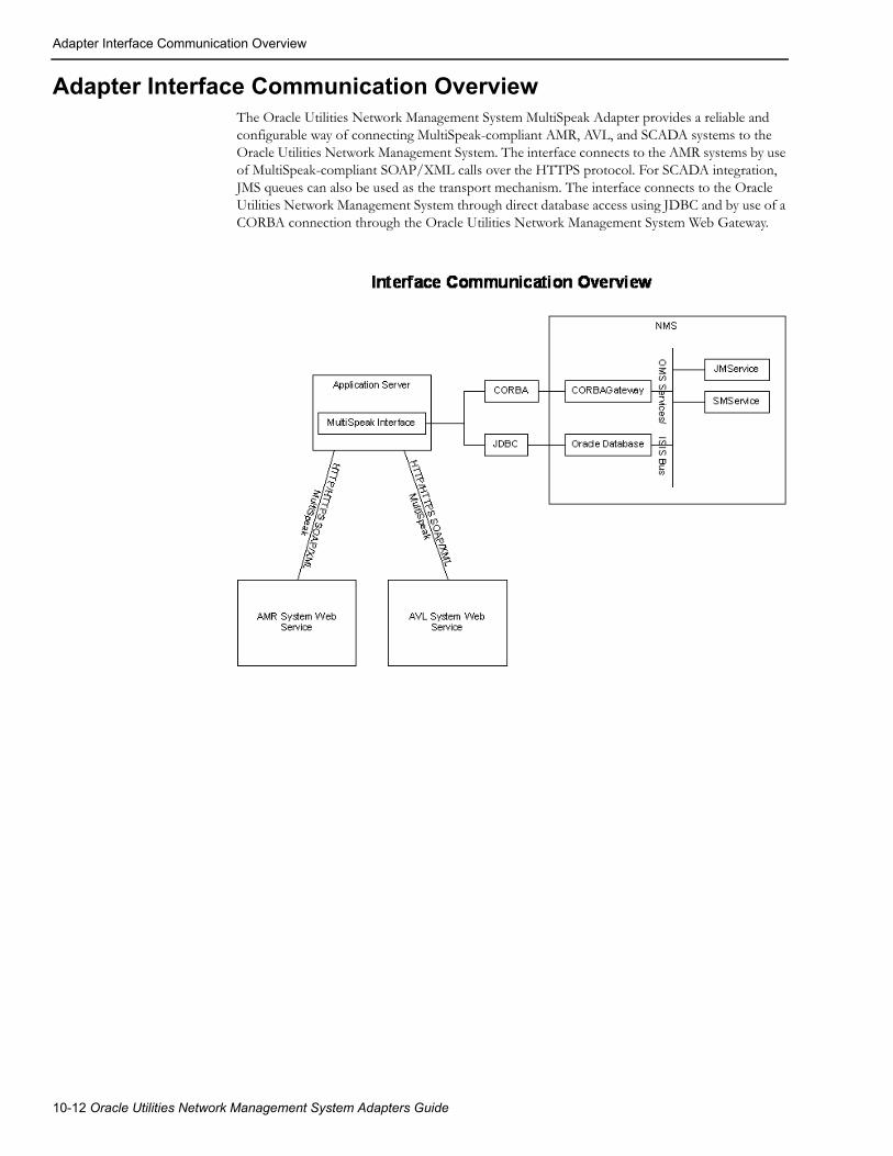
Adapter Interface Communication Overview
Adapter Interface Communication OverviewThe Oracle Utilities Network Management System MultiSpeak Adapter provides a reliable and configurable way of connecting MultiSpeak-compliant AMR, AVL, and SCADA systems to the Oracle Utilities Network Management System. The interface connects to the AMR systems by use of MultiSpeak-compliant SOAP/XML calls over the HTTPS protocol. For SCADA integration, JMS queues can also be used as the transport mechanism. The interface connects to the Oracle Utilities Network Management System through direct database access using JDBC and by use of a CORBA connection through the Oracle Utilities Network Management System Web Gateway.
10-12 Oracle Utilities Network Management System Adapters Guide

Adapter Design
Adapter Design
Supported Data FlowsOracle Utilities Network Management System MultiSpeak Adapter supports following data flows described in the MultiSpeak Web Services Version 4.1 specification.
Oracle Utilities Network Management System to an AMR system:
• InitiateOutageDetectionEventRequest
Oracle Utilities Network Management System requests meter status information from the AMR system.
An AMR system to Oracle Utilities Network Management System:
• ODEventNotification
AMR system reports meter status information to the Oracle Utilities Network Management System.
An AVL system to Oracle Utilities Network Management System:
• AVLChangedNotification
AVL system reports crew location information to the Oracle Utilities Network Management System.
Incoming requests (ODEventNotification and AVLChangedNotification) are authenticated against list of valid Oracle Utilities Network Management System users. Username and password has to be provided in the header of each incoming MultiSpeak message.
AMR Business ProcessesThis section describes the utility business processes related to AMR that can be supported through the Oracle Utilities Network Management System MultiSpeak Adapter.
Outage Detection The vendor AMR system detects no power for a meter, either because of a “last gasp” meter message or from scheduled meter polling. A “power out” call is submitted to Oracle Utilities Network Management System, which generates a probable outage event.
MultiSpeak Adapter 10-13

Adapter Design
PSO VerificationOne customer call is received, generating a probable service outage in Oracle Utilities Network Management System. The Oracle Utilities Network Management System MultiSpeak Adapter is notified of the new probable outage, and the customer meter is pinged to verify power status.
If the meter reports that the power is still on, then we have conflicting information from the customer and the meter, so the outage predication engine will set the status of this event to Verify. At this point, we believe that there is no outage, but that the customer has a problem, such as a blown fuse, within his home. This event must be resolved by a customer service representative contacting the caller to explain the situation to them.
10-14 Oracle Utilities Network Management System Adapters Guide

Adapter Design
PDO VerificationSeveral customer calls are received, which are submitted into the Oracle Utilities Network Management System. The resulting probably outage rolls up to a device. The list of affected AMR customers is provided to the Oracle Utilities Network Management System MultiSpeak Adapter by the Oracle Utilities Network Management System outage prediction engine. The interface submits meter status requests to the AMR for any of the affected meters from which it has not already received a last gasp message. The received meter statuses are sent back to the prediction engine and the predicted outage device may change by moving downstream.
MultiSpeak Adapter 10-15

Adapter Design
Restoration VerificationAn outage event is restored in Oracle Utilities Network Management System, and a list of affected meters is provided by the outage prediction engine to the Oracle Utilities Network Management System MultiSpeak Adapter. The interface submits meter status requests to the AMR for any of the affected meters from which it has not received a “power up” message. The results are passed back to the Oracle Utilities Network Management System and the periodic cycle for getting outage events continues. The received meter statuses are sent back to the prediction engine. A power out status will result in another outage call and a nested outage that still needs restoration.
Unsolicited Power UpsThe AMR system can send unsolicited power up message when it detects that meter power has been restored. The adapter delivers such messages to the outage prediction engine, which uses them as part of Restoration Verification processing.
10-16 Oracle Utilities Network Management System Adapters Guide
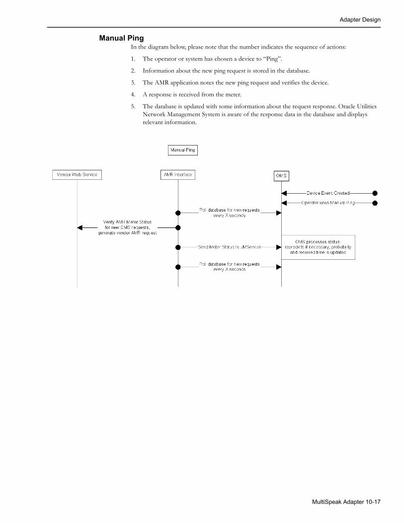
Adapter Design
Manual PingIn the diagram below, please note that the number indicates the sequence of actions:
1. The operator or system has chosen a device to “Ping”.
2. Information about the new ping request is stored in the database.
3. The AMR application notes the new ping request and verifies the device.
4. A response is received from the meter.
5. The database is updated with some information about the request response. Oracle Utilities Network Management System is aware of the response data in the database and displays relevant information.
MultiSpeak Adapter 10-17
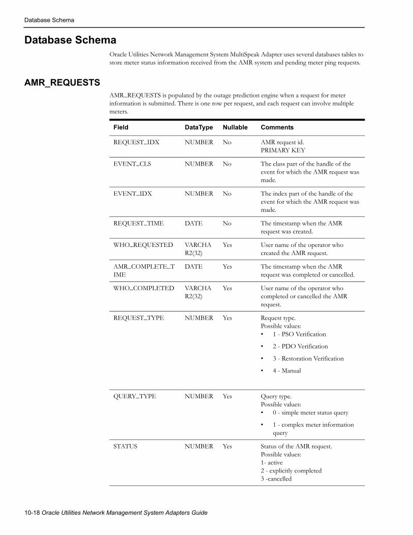
Database Schema
Database SchemaOracle Utilities Network Management System MultiSpeak Adapter uses several databases tables to store meter status information received from the AMR system and pending meter ping requests.
AMR_REQUESTSAMR_REQUESTS is populated by the outage prediction engine when a request for meter information is submitted. There is one row per request, and each request can involve multiple meters.
Field DataType Nullable Comments
REQUEST_IDX NUMBER No AMR request id.PRIMARY KEY
EVENT_CLS NUMBER No The class part of the handle of the event for which the AMR request was made.
EVENT_IDX NUMBER No The index part of the handle of the event for which the AMR request was made.
REQUEST_TIME DATE No The timestamp when the AMR request was created.
WHO_REQUESTED VARCHAR2(32)
Yes User name of the operator who created the AMR request.
AMR_COMPLETE_TIME
DATE Yes The timestamp when the AMR request was completed or cancelled.
WHO_COMPLETED VARCHAR2(32)
Yes User name of the operator who completed or cancelled the AMR request.
REQUEST_TYPE NUMBER Yes Request type.Possible values:• 1 - PSO Verification
• 2 - PDO Verification
• 3 - Restoration Verification
• 4 - Manual
QUERY_TYPE NUMBER Yes Query type.Possible values:• 0 - simple meter status query
• 1 - complex meter information query
STATUS NUMBER Yes Status of the AMR request.Possible values:1- active2 - explicitly completed3 -cancelled
10-18 Oracle Utilities Network Management System Adapters Guide

Database Schema
AMR_RESPONSESThe AMR_RESPONSES table is used to transfer meter status information between the outage prediction engine and the MultiSpeak adapter. The outage prediction engine inserts rows into this table when a request for meter information is submitted. Every request in AMR_RESPONSES is represented by one row for each meter requested. The MultiSpeak adapter updates this table as requested meter status information becomes available.
DEVICE_CLS NUMBER Yes The class part of the handle of the device for which the AMR request was made.
DEVICE_IDX NUMBER Yes The index part of the handle of the device for which the AMR request was made.
NCG NUMBER Yes NCG of the device for which the AMR request was made.
TTL NUMBER(9)
Yes The Time-To-Live of the request in seconds.
Field DataType Nullable Comments
Field DataType Nullable Comments
ID Number No Unique record identifier. PRIMARY KEY
REQUEST_IDX NUMBER Yes AMR request id.
REQUEST_TIME DATE Yes Request timestamp.
METER_NO VARCHAR2(256) Yes Meter number as known to the AMR system
METER_ID NUMBER No NMS meter identifier.
REQUEST_STATUS VARCHAR2(1) Yes Request status.Possible values:• N - new request (not yet sent
to AMR)
• P - pending request (waiting for AMR response)
• S - suppressed request
• R - AMR response received
• C - completed request
STATUS VARCHAR2(256) Yes Meter status received from AMR.Possible values:• ON - meter has power
• OFF - meter does not have power
AMR_ERROR VARCHAR2(256) Yes Error message received from the AMR system.
MultiSpeak Adapter 10-19
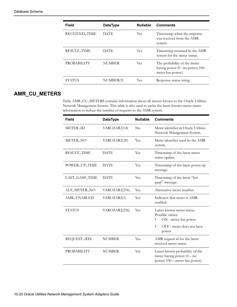
Database Schema
AMR_CU_METERSTable AMR_CU_METERS contains information about all meters known to the Oracle Utilities Network Management System. This table is also used to cache the latest known meter status information to reduce the number of requests to the AMR system.
Field DataType Nullable Comments
METER_ID VARCHAR2(14) No Meter identifier in Oracle Utilities Network Management System.
METER_NO VARCHAR2(20) Yes Meter identifier used by the AMR system.
RESULT_TIME DATE Yes Timestamp of the latest meter status update.
POWER_UP_TIME DATE Yes Timestamp of the latest power-up message.
LAST_GASP_TIME DATE Yes Timestamp of the latest “last gasp” message.
ALT_METER_NO VARCHAR2(256) Yes Alternative meter number.
AMR_ENABLED VARCHAR2(1) Yes Indicator that meter is AMR-enabled.
STATUS VARCHAR2(256) Yes Latest known meter status.Possible values:• ON - meter has power
• OFF - meter does not have power
REQUEST_IDX NUMBER Yes AMR request id for the latest received meter status.
PROBABILITY NUMBER Yes Latest known probability of the meter having power (0 – no power; 100 – meter has power).
RECEIVED_TIME DATE Yes Timestamp when the response was received from the AMR system.
RESULT_TIME DATE Yes Timestamp returned by the AMR system for the meter status.
PROBABILITY NUMBER Yes The probability of the meter having power (0 - no power; 100 - meter has power.)
STATUS NUMBER(3) Yes Response status string
Field DataType Nullable Comments
10-20 Oracle Utilities Network Management System Adapters Guide

SCADA Component
AMR_CU_METERS_HISTORYThe AMR_CU_METERS_HISTORY table is used to store all meter status updates received from the AMR system. This table has the same columns as the AMR_CU_METERS table.
SCADA ComponentThe Oracle Utilities Network Management System MultiSpeak Adapter’s SCADA component has the capability of interacting with SCADA systems having a MultiSpeak-compatible interface.
The following functionality is available:
• Receiving device status updates from SCADA system
• Receiving analog and digital measurement updates from SCADA system
• Mapping of SCADA quality codes (applies to status and measurement updates)
• Receiving tag information from SCADA system
• Receiving alarm information from SCADA system
• Sending control request to SCADA system to operate devices and place/remove tags
• Sending status information for non-SCADA devices to SCADA system
• Dynamic configuration of the mapping between SCADA points and NMS device/attribute pairs
• Display integration between NMS and SCADA system
A single instance of the adapter is capable of communicating with multiple SCADA systems. Several communication links can be configured for each SCADA system. If the currently active link fails, the adapter will automatically switch to the next link.
JMS Transport Mechanism• The JMS transport mechanism is based on the SOAP over JMS specification.
• Two JMS queues are used per communication channel (one for requests and another for responses) to simulate synchronous communication.
• Each individual request is synchronous. The system places the message on the request queue and waits for a reply to arrive on the response queue.
• TextMessage or BytesMessage JMS message classes can be used. In both cases message must be a valid MultiSpeak message.
• Requests and responses are connected through JMSCorrelationID JMS header.
• In the request message, the JMS header JMSReplyTo must contain the queue where response message should be sent.
• SOAP protocol versions 1.1 and 1.2 are supported.
• There is no support for accessing a WSDL over JMS.
MultiSpeak Adapter 10-21

SCADA Component
The following table describes how JMS message properties, specific to SOAP over JMS, are being used:
JMS Message Property Value
SOAPJMS_bindingVersion “1.0”
SOAPJMS_targetServer “SCADA_Server” or “OA_Server” depending on the target system
SOAPJMS_soapAction SOAP action
SOAPJMS_contentType "text/xml; charset="utf-8""
SOAPJMS_isFault “true” for SOAP fault messages
Configuring JMS Support
Incoming Data FlowsSupport for accepting incoming requests over JMS in NMS MultiSpeak adapter is controlled by changing value of the config.multispeak_jms property in $NMS_CONFIG/jconfig/build.properties file.
Possible values:
• none: JMS support is disabled
• single: single JMS queue for all incoming data flows
• multiple: separate JMS queue for each incoming data flow
By default JMS support is disabled.
After modifying the $NMS_CONFIG/jconfig/build.properties file, regenerate the nms-multispeak.ear with the new configuration by executing:
nms-install-config -–java
JNDI names of JMS connection factory and queue(s) used for incoming data flows are fixed.
Connection Factorynms-amr/ConnectionFactory
QueuesSingle Queue Mode - In single queue mode, all incoming requests are sent to the same JMS queue: nms-amr/queue/OA.
10-22 Oracle Utilities Network Management System Adapters Guide

SCADA Component
Multiple Queues ModeWhen multiple incoming queues are used each incoming MultiSpeak data flow uses its own JMS queue.
List of JMS queues and associated MultiSpeak operations:
• nms-amr/queue/OAPingURLPingURL
• nms-amr/queue/OAGetMethodsGetMethods
• nms-amr/queue/OAStatusChangedNotificationByPointIDSCADAStatusChangedNotificationSCADAStatusChangedNotificationByPointID
• nms-amr/queue/OAStatusChangedNotificationByPointIDSyncStatusChangedNotificationByPointID
• nms-amr/queue/OAAnalogChangedNotificationByPointIDSCADAAnalogChangedNotificationSCADAAnalogChangedNotificationByPointID
• nms-amr/queue/OAAnalogChangedNotificationByPointIDSyncAnalogChangedNotificationByPointID
• nms-amr/queue/OATagChangedNotificationByPointIDSCADATagChangedNotificationSCADATagChangedNotificationByPointID
• nms-amr/queue/OATagChangedNotificationByPointIDSyncTagChangedNotificationByPointID
• nms-amr/queue/OAInitiateStatusReadByPointIDInitiateStatusReadByPointID
• nms-amr/queue/OAHighlightObjectInDisplayHighlightObjectInDisplay
Outgoing Data FlowsThe JMS connection factory for outgoing data flows is in defined in the CES_PARAMETERS database table.
The JMS queues used for outgoing messages are configured via SCADA_LINKS and SCADA_LINK_OPS database tables.
MultiSpeak Adapter 10-23

Supported Data Flows
Supported Data Flows
NMS to SCADA
Heartbeat
PingURLThe adapter periodically sends PingURL message to the each configured SCADA system. Failure to send the message or error response from SCADA system (reply contains errorObject element) triggers switch to alternate link (if available). Upon restoration of communication with the SCADA system (PingURL has been sent successfully) synchronization sequence is executed.
PingURL request example
<S:Envelope xmlns:S="http://schemas.xmlsoap.org/soap/envelope/"> <S:Header> <ns4:MultiSpeakMsgHeader xmlns:ns4="http://www.multispeak.org/ Version_4.1_Release" xmlns:ns3="http://www.w3.org/1999/xlink" xmlns:ns2="gml" xmlns="cpsm" /> </S:Header> <S:Body> <ns4:PingURL xmlns:ns4="http://www.multispeak.org/Version_4.1_Release" xmlns:ns3="http://www.w3.org/1999/xlink" xmlns:ns2="gml" xmlns="cpsm" /> </S:Body></S:Envelope>
Synchronization/Integrity checkThe purpose of the synchronization sequence is to bring the state of devices in the NMS model up-to-date with the SCADA system. NMS supports two synchronization methods for device statuses, digital and analog measurements. At the beginning of the synchronization sequence, NMS will make GetMethods call to determine the list of operations supported by the SCADA system. Synchronization method selection is based on configured preferred method and available SCADA operations.
The synchronization sequence is executed automatically after the connection to a SCADA system is established. It also can be triggered manually using following command
Action -java multispeak.SCADA resync
GetMethodsGetMethods retrieves lists of operations the SCADA system implements. It is used to determine available modes of syn-chronization. It is also used to determine if control requests can be send to SCADA.
GetMethods request and response example
<S:Envelope xmlns:S="http://schemas.xmlsoap.org/soap/envelope/"> <S:Header> <ns4:MultiSpeakMsgHeader xmlns:ns4="http://www.multispeak.org/ Version_4.1_Release" xmlns:ns3="http://www.w3.org/1999/xlink" xmlns:ns2="gml" xmlns="cpsm" /> </S:Header> <S:Body> <ns4:GetMethods xmlns:ns4="http://www.multispeak.org/Version_4.1_Release" xmlns:ns3="http://www.w3.org/1999/xlink" xmlns:ns2="gml" xmlns="cpsm" /> </S:Body></S:Envelope>
10-24 Oracle Utilities Network Management System Adapters Guide

Supported Data Flows
<soapenv:Envelope xmlns:soapenv="http://schemas.xmlsoap.org/soap/envelope/" xmlns:ver="http://www.multispeak.org/Version_4.1_Release"> <soapenv:Header> <ver:MultiSpeakMsgHeader/> </soapenv:Header> <soapenv:Body> <ver:GetMethodsResponse> <ver:GetMethodsResult> <ver:string>PingURL</ver:string> <ver:string>GetMethods</ver:string> <ver:string>InitiateStatusReadByPointID</ver:string> <ver:string>InitiateAnalogReadByPointID</ver:string> <ver:string>InitiateControl</ver:string> <ver:string>GetAllSCADAStatus</ver:string> <ver:string>GetAllSCADAAnalogs</ver:string> <ver:string>GetAllSCADATags</ver:string> </ver:GetMethodsResult> </ver:GetMethodsResponse> </soapenv:Body></soapenv:Envelope>
GetAllSCADAStatus, GetAllSCADAAnalogsThe first synchronization method involves NMS invoking GetAllSCADAStatus and GetAllSCADAAnalogs operations to request the latest device statuses, digital and analog measurements from the SCADA. SCADA provides the requested information synchronously in the response message.
The MultiSpeak specification allows data to be returned in chunks by the SCADA system. In this case, NMS would have to make multiple GetAllSCADAXXX calls. The element lastReceived is included so that large sets of data can be returned in manageable blocks. lastReceived will carry an empty string the first time in a session that this method is invoked. When multiple calls to this method are required to obtain all of the data, the lastReceived should carry the objectID of the last data instance received in subsequent calls. If the ObjectsRemaining field is present in the MultiSpeak reply message’s message header, it will be used to determine when all of the data has been received. If the ObjectsRemaining field is not present, the empty result set will signal the end of the data.
GetAllSCADAStatus request and response example
<S:Envelope xmlns:S="http://schemas.xmlsoap.org/soap/envelope/"> <S:Header> <ns4:MultiSpeakMsgHeader xmlns:ns4="http://www.multispeak.org/ Version_4.1_Release" xmlns:ns3="cpsm" xmlns:ns2="http://www.w3.org/1999/xlink" xmlns:ns1="gml" Pwd="test" UserID="nms" /> </S:Header> <S:Body> <ns4:GetAllSCADAStatus xmlns:ns4="http://www.multispeak.org/ Version_4.1_Release" xmlns:ns3="cpsm" xmlns:ns2="http://www.w3.org/1999/xlink" xmlns:ns1="gml"> <ns4:lastReceived></ns4:lastReceived> </ns4:GetAllSCADAStatus> </S:Body></S:Envelope>
MultiSpeak Adapter 10-25
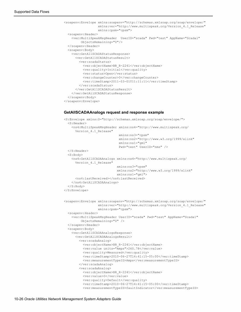
Supported Data Flows
<soapenv:Envelope xmlns:soapenv="http://schemas.xmlsoap.org/soap/envelope/" xmlns:ver="http://www.multispeak.org/Version_4.1_Release" xmlns:cpsm="cpsm"> <soapenv:Header> <ver:MultiSpeakMsgHeader UserID="scada" Pwd="test" AppName="Scada1" ObjectsRemaining="0"/> </soapenv:Header> <soapenv:Body> <ver:GetAllSCADAStatusResponse> <ver:GetAllSCADAStatusResult> <ver:scadaStatus> <ver:objectName>BR_R-2241</ver:objectName> <ver:quality>Initial</ver:quality> <ver:status>Open</ver:status> <ver:changeCounter>0</ver:changeCounter> <ver:timeStamp>2011-03-01T11:11:11</ver:timeStamp> </ver:scadaStatus> </ver:GetAllSCADAStatusResult> </ver:GetAllSCADAStatusResponse> </soapenv:Body></soapenv:Envelope>
GetAllSCADAAnalogs request and response example
<S:Envelope xmlns:S="http://schemas.xmlsoap.org/soap/envelope/"> <S:Header> <ns4:MultiSpeakMsgHeader xmlns:ns4="http://www.multispeak.org/ Version_4.1_Release" xmlns:ns3="cpsm" xmlns:ns2="http://www.w3.org/1999/xlink" xmlns:ns1="gml" Pwd="test" UserID="nms" /> </S:Header> <S:Body> <ns4:GetAllSCADAAnalogs xmlns:ns4="http://www.multispeak.org/ Version_4.1_Release" xmlns:ns3="cpsm" xmlns:ns2="http://www.w3.org/1999/xlink" xmlns:ns1="gml"> <ns4:lastReceived></ns4:lastReceived> </ns4:GetAllSCADAAnalogs> </S:Body></S:Envelope>
<soapenv:Envelope xmlns:soapenv="http://schemas.xmlsoap.org/soap/envelope/" xmlns:ver="http://www.multispeak.org/Version_4.1_Release" xmlns:cpsm="cpsm"> <soapenv:Header> <ver:MultiSpeakMsgHeader UserID="scada" Pwd="test" AppName="Scada1" ObjectsRemaining="0" /> </soapenv:Header> <soapenv:Body> <ver:GetAllSCADAAnalogsResponse> <ver:GetAllSCADAAnalogsResult> <ver:scadaAnalog> <ver:objectName>BR_R-2241</ver:objectName> <ver:value units="Amps">260.78</ver:value> <ver:quality>Measured</ver:quality> <ver:timeStamp>2010-06-27T14:41:15-05:00</ver:timeStamp> <ver:measurementTypeID>Amps</ver:measurementTypeID> </ver:scadaAnalog> <ver:scadaAnalog> <ver:objectName>BR_R-2241</ver:objectName> <ver:value>0</ver:value> <ver:quality>Default</ver:quality> <ver:timeStamp>2010-06-27T14:41:15-05:00</ver:timeStamp> <ver:measurementTypeID>faultIndicator</ver:measurementTypeID>
10-26 Oracle Utilities Network Management System Adapters Guide

Supported Data Flows
</ver:scadaAnalog> </ver:GetAllSCADAAnalogsResult> </ver:GetAllSCADAAnalogsResponse> </soapenv:Body></soapenv:Envelope>
GetAllSCADAAnalogs is used for both digital and analog measurements.
InitiateStatusReadByPointID, InitiateAnalogReadByPointID, InitiateTagReadyByPointIDThe second synchronization method uses InitiateXXXReadByPointID operations to request latest device statuses, tags, digital and analog measurements from the SCADA. SCADA provides requested information asynchronously by sending XXXChangedNotificationByPointID messages to NMS. To avoid having to send all SCADA points known to NMS an empty list of SCADA points can be used to indicate desire to initiate read for all SCADA points. Operation InitiateTagReadByPointID is not part of MultiSpeak 4.1 specification.
InitiateStatusReadByPointID and InitiateAnalogReadByPointID request exam-ples
<S:Envelope xmlns:S="http://schemas.xmlsoap.org/soap/envelope/"> <S:Header> <ns4:MultiSpeakMsgHeader xmlns:ns4="http://www.multispeak.org/Version_4.1_Release" xmlns:ns3="cpsm" xmlns:ns2="http://www.w3.org/1999/xlink" xmlns:ns1="gml" Pwd="test" UserID="nms" /> </S:Header> <S:Body> <ns4:InitiateStatusReadByPointID xmlns:ns4="http://www.multispeak.org/Version_4.1_Release" xmlns:ns3="cpsm" xmlns:ns2="http://www.w3.org/1999/xlink" xmlns:ns1="gml"> <ns4:pointIDs /> <ns4:responseURL>https://nms-server:7002/nms-amr/oa</ns4:responseURL> <ns4:transactionID>1300163600187</ns4:transactionID> <ns4:expTime units="Hours">1.0</ns4:expTime> </ns4:InitiateStatusReadByPointID> </S:Body></S:Envelope>
<S:Envelope xmlns:S="http://schemas.xmlsoap.org/soap/envelope/"> <S:Header> <ns4:MultiSpeakMsgHeader xmlns:ns4="http://www.multispeak.org/Version_4.1_Release" xmlns:ns3="cpsm" xmlns:ns2="http://www.w3.org/1999/xlink" xmlns:ns1="gml" Pwd="test" UserID="nms" /> </S:Header> <S:Body> <ns4:InitiateAnalogReadByPointID xmlns:ns4="http://www.multispeak.org/Version_4.1_Release" xmlns:ns3="cpsm" xmlns:ns2="http://www.w3.org/1999/xlink" xmlns:ns1="gml"> <ns4:pointIDs /> <ns4:responseURL>https://nms-server:7002/nms-amr/oa</ns4:responseURL> <ns4:transactionID>1300163600203</ns4:transactionID> <ns4:expTime units="Hours">1.0</ns4:expTime> </ns4:InitiateAnalogReadByPointID> </S:Body></S:Envelope>
MultiSpeak Adapter 10-27
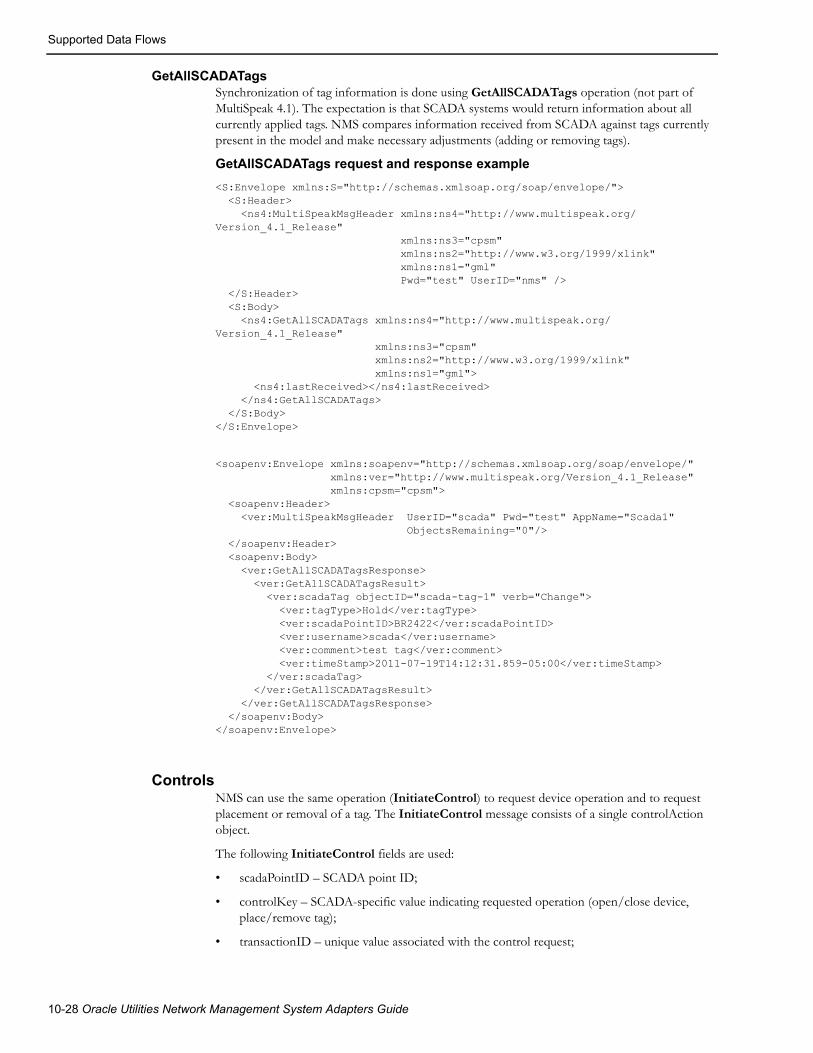
Supported Data Flows
GetAllSCADATagsSynchronization of tag information is done using GetAllSCADATags operation (not part of MultiSpeak 4.1). The expectation is that SCADA systems would return information about all currently applied tags. NMS compares information received from SCADA against tags currently present in the model and make necessary adjustments (adding or removing tags).
GetAllSCADATags request and response example
<S:Envelope xmlns:S="http://schemas.xmlsoap.org/soap/envelope/"> <S:Header> <ns4:MultiSpeakMsgHeader xmlns:ns4="http://www.multispeak.org/Version_4.1_Release" xmlns:ns3="cpsm" xmlns:ns2="http://www.w3.org/1999/xlink" xmlns:ns1="gml" Pwd="test" UserID="nms" /> </S:Header> <S:Body> <ns4:GetAllSCADATags xmlns:ns4="http://www.multispeak.org/Version_4.1_Release" xmlns:ns3="cpsm" xmlns:ns2="http://www.w3.org/1999/xlink" xmlns:ns1="gml"> <ns4:lastReceived></ns4:lastReceived> </ns4:GetAllSCADATags> </S:Body></S:Envelope>
<soapenv:Envelope xmlns:soapenv="http://schemas.xmlsoap.org/soap/envelope/" xmlns:ver="http://www.multispeak.org/Version_4.1_Release" xmlns:cpsm="cpsm"> <soapenv:Header> <ver:MultiSpeakMsgHeader UserID="scada" Pwd="test" AppName="Scada1" ObjectsRemaining="0"/> </soapenv:Header> <soapenv:Body> <ver:GetAllSCADATagsResponse> <ver:GetAllSCADATagsResult> <ver:scadaTag objectID="scada-tag-1" verb="Change"> <ver:tagType>Hold</ver:tagType> <ver:scadaPointID>BR2422</ver:scadaPointID> <ver:username>scada</ver:username> <ver:comment>test tag</ver:comment> <ver:timeStamp>2011-07-19T14:12:31.859-05:00</ver:timeStamp> </ver:scadaTag> </ver:GetAllSCADATagsResult> </ver:GetAllSCADATagsResponse> </soapenv:Body></soapenv:Envelope>
ControlsNMS can use the same operation (InitiateControl) to request device operation and to request placement or removal of a tag. The InitiateControl message consists of a single controlAction object.
The following InitiateControl fields are used:
• scadaPointID – SCADA point ID;
• controlKey – SCADA-specific value indicating requested operation (open/close device, place/remove tag);
• transactionID – unique value associated with the control request;
10-28 Oracle Utilities Network Management System Adapters Guide

Supported Data Flows
• responseURL – URL of NMS web service , which should be used to report outcome of the requested control action.
Notes:
• Field function is required, but NMS will not use it. Field function will always contain the following value: Direct operate.
• NMS will not issue separate select and operate commands.
InitiateControl request example
<soapenv:Envelope xmlns:soapenv=http://schemas.xmlsoap.org/soap/envelope/ xmlns:ver="http://www.multispeak.org/Version_4.1_Release"> <soapenv:Header> <ver:MultiSpeakMsgHeader UserID="nms" Pwd="test" TimeStamp="2011-03-19T20:04:37"/> </soapenv:Header> <soapenv:Body> <ver:InitiateControl> <ver:controlAction> <ver:scadaPointID>BR_R-2241</ver:scadaPointID> <ver:controlKey>open</ver:controlKey> <ver:function>Direct operate</ver:function> <ver:relayType>Normal</ver:relayType> </ver:controlAction> <ver:responseURL>https://nms-server:7002/nms-amr/oa</ver:responseURL> <ver:transactionID>12345</ver:transactionID> </ver:InitiateControl> </soapenv:Body></soapenv:Envelope>
Operating a SCADA-controlled device1. NMS user instructs open of a SCADA-controlled device.
2. Instructed flag is placed on the device in NMS. The device remains closed in NMS model.
3. NMS sends InitiateControl message to the SCADA system.
4. If requested control action has been successfully executed then:
a. SCADA sends SCADAStatusChangedNotification with the new status of the operated device
b. NMS updates device status in the model and removes Instructed flag
3. Regardless of the outcome of the requested control action
a. SCADA sends ControlActionCompleted message to indicate whether requested control action was successful or not
b. In case of negative outcome NMS removes Instructed flag. Device status remains unchanged.
Note: When SCADA sends ControlActionCompleted message to NMS in case of success NMS will not update device status in its model until SCADAStatusChangedNotification message has been received.
MultiSpeak Adapter 10-29

Supported Data Flows
Placing or removing a tag on a SCADA-controlled device1. NMS user instructs placement of a HOLD tag on a SCADA-controlled device.
2. Instructed flag is placed on the device in NMS. The device remains closed in the NMS model.
3. NMS sends InitiateControl message to the SCADA system.
4. If requested control action has been successfully executed then:
a. SCADA sends SCADATagChangedNotification with the new status of the operated device.
b. NMS updates device status in the model and removes Instructed flag.
3. If requested control action has NOT been successfully executed then:
a. SCADA sends ControlActionCompleted message to indicate that requested control action has not been executed.
b. NMS removes Instructed flag, device status remains unchanged.
Note: SCADA can send ControlActionCompleted message to NMS in case of success, but NMS will not update tag information in its model until SCADATagChangedNotification message has been received.
Outgoing Device StatusesIf SCADA system has knowledge of the NMS electrical model, then the adapter can be configured to send device status information for non-SCADA devices in the NMS model to the SCADA system.
The SCADA system plugin method buildScadaPointId is used to construct SCADA point id for non-SCADA devices.
SCADAStatusChangedNotificationSends NMS device status changes to SCADA system.
StatusChangedNotificationByPointIDSends NMS device status information to SCADA system in response to InitiateStatusReadByPointID request. NMS only returns information for devices which are not in the nominal state to reduce volume of data.
Display Integration
HighlightObjectInDisplayThis message causes SCADA system to focus display on a particular SCADA point.
10-30 Oracle Utilities Network Management System Adapters Guide
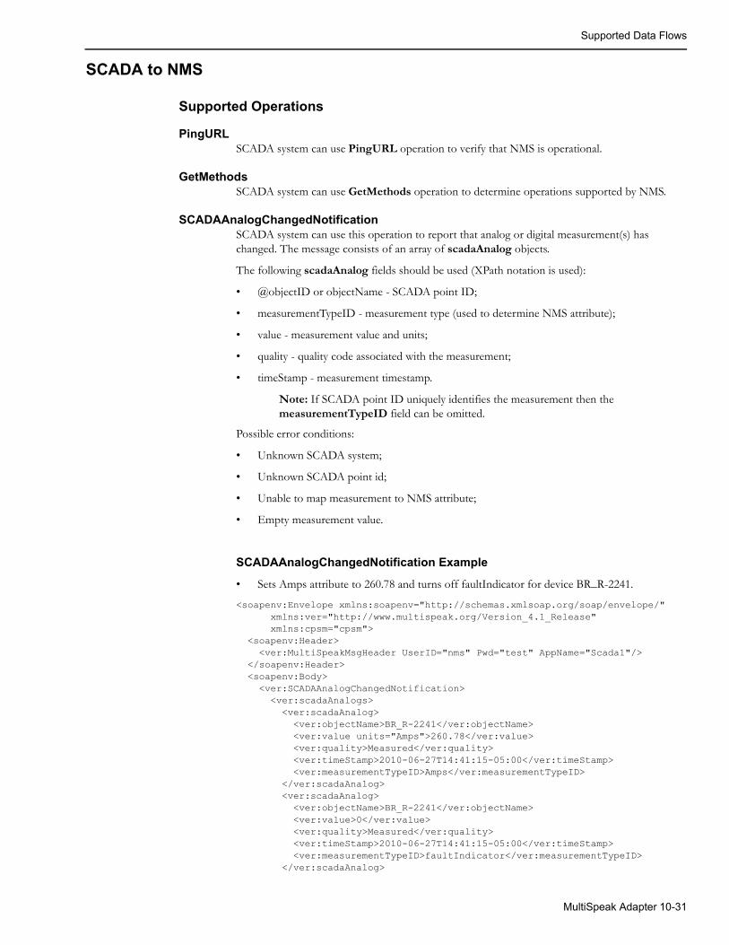
Supported Data Flows
SCADA to NMS
Supported Operations
PingURLSCADA system can use PingURL operation to verify that NMS is operational.
GetMethodsSCADA system can use GetMethods operation to determine operations supported by NMS.
SCADAAnalogChangedNotificationSCADA system can use this operation to report that analog or digital measurement(s) has changed. The message consists of an array of scadaAnalog objects.
The following scadaAnalog fields should be used (XPath notation is used):
• @objectID or objectName - SCADA point ID;
• measurementTypeID - measurement type (used to determine NMS attribute);
• value - measurement value and units;
• quality - quality code associated with the measurement;
• timeStamp - measurement timestamp.
Note: If SCADA point ID uniquely identifies the measurement then the measurementTypeID field can be omitted.
Possible error conditions:
• Unknown SCADA system;
• Unknown SCADA point id;
• Unable to map measurement to NMS attribute;
• Empty measurement value.
SCADAAnalogChangedNotification Example
• Sets Amps attribute to 260.78 and turns off faultIndicator for device BR_R-2241.
<soapenv:Envelope xmlns:soapenv="http://schemas.xmlsoap.org/soap/envelope/" xmlns:ver="http://www.multispeak.org/Version_4.1_Release" xmlns:cpsm="cpsm"> <soapenv:Header> <ver:MultiSpeakMsgHeader UserID="nms" Pwd="test" AppName="Scada1"/> </soapenv:Header> <soapenv:Body> <ver:SCADAAnalogChangedNotification> <ver:scadaAnalogs> <ver:scadaAnalog> <ver:objectName>BR_R-2241</ver:objectName> <ver:value units="Amps">260.78</ver:value> <ver:quality>Measured</ver:quality> <ver:timeStamp>2010-06-27T14:41:15-05:00</ver:timeStamp> <ver:measurementTypeID>Amps</ver:measurementTypeID> </ver:scadaAnalog> <ver:scadaAnalog> <ver:objectName>BR_R-2241</ver:objectName> <ver:value>0</ver:value> <ver:quality>Measured</ver:quality> <ver:timeStamp>2010-06-27T14:41:15-05:00</ver:timeStamp> <ver:measurementTypeID>faultIndicator</ver:measurementTypeID> </ver:scadaAnalog>
MultiSpeak Adapter 10-31

Supported Data Flows
</ver:scadaAnalogs> </ver:SCADAAnalogChangedNotification> </soapenv:Body></soapenv:Envelope>
SCADAAnalogChangedNotificationByPointIDThe SCADA system can use this operation to report that an analog or digital measurement has changed. The message consists of a single scadaAnalog object.
The following scadaAnalog fields should be used:
• @objectID or objectName - SCADA point ID;
• measurementTypeID - measurement type (used to determine NMS attribute);
• value - measurement value and units;
• quality - quality code associated with the measurement;
• timeStamp - measurement timestamp.
Possible error conditions:
• Unknown SCADA system;
• Unknown SCADA point id;
• Unable to map measurement to NMS attribute;
• Empty measurement value.
AnalogChangedNotificationByPointIDThis operation is used by SCADA system to respond to the InitiateAnalogReadByPointID request made by NMS.
• The message format is the same as SCADAAnalogChangedNotification with one additional field 'transactionID'.
• Its value has to match the value of the 'transactionID' field in the InitiateAnalogReadByPointID message the SCADA system is responding to.
SCADAStatusChangedNotificationThe SCADA system will use this operation to report that one or more devices have changed status. The message consists of an array of scadaStatus objects.
The following scadaStatus fields should be used:
• @objectID or objectName - SCADA point ID;
• status - SCADA device status (Open/Closed);
• quality - quality code associated with the status update;
• changeCounter - number of device status changes since the last report;
• timeStamp - device operation timestamp.
Possible error conditions:
• Unknown SCADA system;
• Unknown SCADA point id;
• Invalid status value.
10-32 Oracle Utilities Network Management System Adapters Guide

Supported Data Flows
SCADAStatusChangedNotification examples
1. Opens device BR_R-2241
<soapenv:Envelope xmlns:soapenv="http://schemas.xmlsoap.org/soap/envelope/" xmlns:ver="http://www.multispeak.org/Version_4.1_Release" xmlns:cpsm="cpsm"> <soapenv:Header> <ver:MultiSpeakMsgHeader UserID="nms" Pwd="test" AppName="Scada1"/> </soapenv:Header> <soapenv:Body> <ver:SCADAStatusChangedNotification> <ver:scadaStatuses> <ver:scadaStatus> <ver:objectName>BR_R-2241</ver:objectName> <ver:quality>Measured</ver:quality> <ver:status>Open</ver:status> <ver:changeCounter>1</ver:changeCounter> <ver:timeStamp>2011-03-04T11:44:10</ver:timeStamp> </ver:scadaStatus> </ver:scadaStatuses> </ver:SCADAStatusChangedNotification> </soapenv:Body></soapenv:Envelope>
2. Closes device BR_R-2241
<soapenv:Envelope xmlns:soapenv="http://schemas.xmlsoap.org/soap/envelope/" xmlns:ver="http://www.multispeak.org/Version_4.1_Release" xmlns:cpsm="cpsm"> <soapenv:Header> <ver:MultiSpeakMsgHeader UserID="nms" Pwd="test" AppName="Scada1"/> </soapenv:Header> <soapenv:Body> <ver:SCADAStatusChangedNotification> <ver:scadaStatuses> <ver:scadaStatus> <ver:objectName>BR_R-2241</ver:objectName> <ver:quality>Measured</ver:quality> <ver:status>Closed</ver:status> <ver:changeCounter>1</ver:changeCounter> <ver:timeStamp>2011-03-04T11:44:10</ver:timeStamp> </ver:scadaStatus> </ver:scadaStatuses> </ver:SCADAStatusChangedNotification> </soapenv:Body></soapenv:Envelope>
MultiSpeak Adapter 10-33

Supported Data Flows
SCADAStatusChangedNotificationByPointIDThe SCADA system can use this operation to report that the status of a device has changed. The message consists of a single scadaStatus object.
The following scadaStatus fields should be used:
• @objectID or objectName - SCADA point ID;
• status - SCADA device status (Open/Closed);
• quality - quality code associated with the status update;
• changeCounter - number of device status changes since the last report;
• timeStamp - device operation timestamp.
Possible error conditions:
• Unknown SCADA system;
• Unknown SCADA point id;
• Invalid status value.
StatusChangedNotificationByPointIDThis operation is used by the SCADA system to respond to the InitiateStatusReadByPointID request made by NMS.
• Message format is the same as SCADAStatusChangedNotification with one additional field 'transactionID'.
• Its value has to match value of the 'transactionID' field in the InitiateStatusReadByPointID message the SCADA system is responding to.
SCADATagChangedNotificationThe SCADA system can use this operation to report that there has been a change in tag(s) placed on devices in the SCADA system. The message consists of an array of scadaTag objects.
The following scadaTag fields should be used:
• @objectID - SCADA tag identifier;
• scadaPointID - SCADA point id;
• @verb - action (New/Change/Delete);
• tagType - SCADA tag type;
• username - SCADA operator's user name;
• comment - tag comments, notes;
• timeStamp - tag operation timestamp.
Possible error conditions:
• Unknown SCADA system;
• Unknown SCADA point id;
• Invalid tag type;
• Unsupported action.
This operation does not exist in MultiSpeak 4.1 specification.
10-34 Oracle Utilities Network Management System Adapters Guide

Supported Data Flows
SCADATagChangedNotification examples
1. Place HOLD tag on device BR2422
<soapenv:Envelope xmlns:soapenv="http://schemas.xmlsoap.org/soap/envelope/" xmlns:ver="http://www.multispeak.org/Version_4.1_Release" xmlns:cpsm="cpsm"> <soapenv:Header> <ver:MultiSpeakMsgHeader UserID="nms" Pwd="test" AppName="Scada1"/> </soapenv:Header> <soapenv:Body> <ver:SCADATagChangedNotification> <ver:scadaTags> <ver:scadaTag objectID="scada-tag-1" verb="New"> <ver:tagType>Hold</ver:tagType> <ver:scadaPointID>BR2422</ver:scadaPointID> <ver:username>scada</ver:username> <ver:comment>test tag</ver:comment> <ver:timeStamp>2011-07-19T14:12:31.859-05:00</ver:timeStamp> </ver:scadaTag> </ver:scadaTags> </ver:SCADATagChangedNotification> </soapenv:Body></soapenv:Envelope>
2. Update HOLD tag on device BR2422
<soapenv:Envelope xmlns:soapenv="http://schemas.xmlsoap.org/soap/envelope/" xmlns:ver="http://www.multispeak.org/Version_4.1_Release" xmlns:cpsm="cpsm"> <soapenv:Header> <ver:MultiSpeakMsgHeader UserID="nms" Pwd="test" AppName="Scada1"/> </soapenv:Header> <soapenv:Body> <ver:SCADATagChangedNotification> <ver:scadaTags> <ver:scadaTag objectID="scada-tag-1" verb="Change"> <ver:tagType>Hold</ver:tagType> <ver:scadaPointID>BR2422</ver:scadaPointID> <ver:username>scada2</ver:username> <ver:comment>updated test tag</ver:comment> <ver:timeStamp>2011-07-19T14:13:31.859-05:00</ver:timeStamp> </ver:scadaTag> </ver:scadaTags> </ver:SCADATagChangedNotification> </soapenv:Body></soapenv:Envelope>
MultiSpeak Adapter 10-35

Supported Data Flows
3. Remove HOLD tag from device BR2422
<soapenv:Envelope xmlns:soapenv="http://schemas.xmlsoap.org/soap/envelope/" xmlns:ver="http://www.multispeak.org/Version_4.1_Release" xmlns:cpsm="cpsm"> <soapenv:Header> <ver:MultiSpeakMsgHeader UserID="nms" Pwd="test" AppName="Scada1"/> </soapenv:Header> <soapenv:Body> <ver:SCADATagChangedNotification> <ver:scadaTags> <ver:scadaTag objectID="scada-tag-1" verb="Delete"> <ver:tagType>Hold</ver:tagType> <ver:scadaPointID>BR2422</ver:scadaPointID> <ver:username>scada</ver:username> <ver:comment>updated test tag</ver:comment> <ver:timeStamp>2011-07-19T14:14:31.859-05:00</ver:timeStamp> </ver:scadaTag> </ver:scadaTags> </ver:SCADATagChangedNotification> </soapenv:Body></soapenv:Envelope>
TagChangedNotificationByPointIDThis operation is used by the SCADA system to respond to the InitiateTagReadByPointID request made by NMS.
• The message format is the same as SCADATagChangedNotification with one additional field 'transactionID'.
• Its value has to match value of the 'transactionID' field in the InitiateTagReadByPointID message SCADA system is responding to.
• This operation does not exist in MultiSpeak 4.1 specification.
ControlActionCompletedThe SCADA system can use this operation to report to NMS the outcome of a control action requested by the InitiateControl operation. The message consists of a single of scadaControl object. In case of successful control action field, the controlStatus should contain value “Control accepted.” Any other value is interpreted as control failure.
ControlActionCompleted example
<soapenv:Envelope xmlns:soapenv="http://schemas.xmlsoap.org/soap/envelope/" xmlns:ver="http://www.multispeak.org/Version_4.1_Release"> <soapenv:Header> <ver:MultiSpeakMsgHeader UserID="scada" Pwd="test" AppName="Scada1"/> </soapenv:Header> <soapenv:Body> <ver:ControlActionCompleted> <ver:controlAction> <ver:scadaPointID>BR2422</ver:scadaPointID> <ver:function>Direct operate</ver:function> <ver:relayType>Normal</ver:relayType> <ver:controlStatus>Control accepted</ver:controlStatus> </ver:controlAction> <ver:transactionID>12345</ver:transactionID> </ver:ControlActionCompleted> </soapenv:Body></soapenv:Envelope>
10-36 Oracle Utilities Network Management System Adapters Guide

Supported Data Flows
VoltageAlarmNotificationThe SCADA system can use this operation to report alarms to NMS. The message consists of an array of voltageA-larm objects.
The following voltageAlarm fields should be used:
• @objectID - SCADA alarm identifier;
• sourceIdentifier - SCADA point id;
• sourceIdentifier/@name - attribute name;
• @verb - action (only New is allowed);
• @errorString - alarm description;
• comments - alarm description;
• eventTime - SCADA alarm timestamp;
• voltageAlarmList/voltageAlarmItem[1]/voltageValue - SCADA measurement value, which caused the alarm;
• voltageAlarmList/voltageAlarmItem[1]/quality - SCADA quality code;
• voltageAlarmList/voltageAlarmItem[1]/analogCondition - SCADA limit violation;
• voltageAlarmList/voltageAlarmItem[1]/phaseCode - SCADA alarm phases.
For alarms SCADA quality code is passed “as-is.” Configured quality code mapping rules are not applied in this case.
Possible error conditions:
• Unknown SCADA system;
• Unknown SCADA point id;
• Unsupported action.
VoltageAlarmNotification example
<soapenv:Envelope xmlns:soapenv="http://schemas.xmlsoap.org/soap/envelope/" xmlns:ver="http://www.multispeak.org/Version_4.1_Release" xmlns:cpsm="cpsm"> <soapenv:Header> <ver:MultiSpeakMsgHeader UserID="nms1" Pwd="systems" AppName="SoapUI"/> </soapenv:Header> <soapenv:Body> <ver:VoltageAlarmNotification> <ver:alarms> <ver:voltageAlarm objectID="alarm-1" verb="New" errorString="alarm test"> <ver:comments>comment</ver:comments> <ver:sourceIdentifier name="Volts">BR2422</ver:sourceIdentifier> <ver:eventTime>2011-05-11T10:05:25.484-05:00</ver:eventTime> <ver:voltageAlarmList> <ver:voltageAlarmItem> <ver:voltageValue units="V">100</ver:voltageValue> <ver:quality>Measured</ver:quality> <ver:analogCondition>H1</ver:analogCondition> <ver:phaseCode>BC</ver:phaseCode> </ver:voltageAlarmItem> </ver:voltageAlarmList> </ver:voltageAlarm> </ver:alarms> </ver:VoltageAlarmNotification> </soapenv:Body></soapenv:Envelope>
MultiSpeak Adapter 10-37

Supported Data Flows
InitiateStatusReadByPointIDInitiates process of sending device status information for non-SCADA devices from NMS to SCADA as series of StatusChangedNotificationByPointID messages.
HighlightObjectInDisplayCauses NMS viewer to focus on given SCADA point. Viewer window has to be open (this message does not open viewer window).
MultiSpeak Message HeaderThe attributes UserID and Pwd in the MultiSpeak message header are used for authentication. These attributes should be populated with valid NMS credentials for all messages coming to NMS with exception of PingURL and GetMethods.
The attribute AppName in the MultiSpeak message header must be populated with the name of the SCADA system the message originated from. It is checked against the SCADA systems defined in the SCADA_IDS database table.
10-38 Oracle Utilities Network Management System Adapters Guide
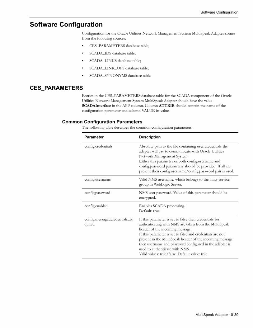
Software Configuration
Software ConfigurationConfiguration for the Oracle Utilities Network Management System MultiSpeak Adapter comes from the following sources:
• CES_PARAMETERS database table;
• SCADA_IDS database table;
• SCADA_LINKS database table;
• SCADA_LINK_OPS database table;
• SCADA_SYNONYMS database table.
CES_PARAMETERSEntries in the CES_PARAMETERS database table for the SCADA component of the Oracle Utilities Network Management System MultiSpeak Adapter should have the value SCADAInterface in the APP column. Column ATTRIB should contain the name of the configuration parameter and column VALUE its value.
Common Configuration ParametersThe following table describes the common configuration parameters.
Parameter Description
config.credentials Absolute path to the file containing user credentials the adapter will use to communicate with Oracle Utilities Network Management System.Either this parameter or both config.username and config.password parameters should be provided. If all are present then config.username/config.password pair is used.
config.username Valid NMS username, which belongs to the 'nms-service' group in WebLogic Server.
config.password NMS user password. Value of this parameter should be encrypted.
config.enabled Enables SCADA processing.Default: true
config.message_credentials_required
If this parameter is set to false then credentials for authenticating with NMS are taken from the MultiSpeak header of the incoming message.If this parameter is set to false and credentials are not present in the MultiSpeak header of the incoming message then username and password configured in the adapter is used to authenticate with NMS.Valid values: true/false. Default value: true
MultiSpeak Adapter 10-39
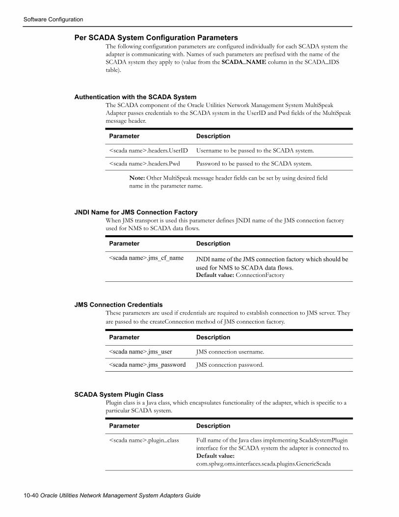
Software Configuration
Per SCADA System Configuration ParametersThe following configuration parameters are configured individually for each SCADA system the adapter is communicating with. Names of such parameters are prefixed with the name of the SCADA system they apply to (value from the SCADA_NAME column in the SCADA_IDS table).
Authentication with the SCADA System The SCADA component of the Oracle Utilities Network Management System MultiSpeak Adapter passes credentials to the SCADA system in the UserID and Pwd fields of the MultiSpeak message header.
Parameter Description
<scada name>.headers.UserID Username to be passed to the SCADA system.
<scada name>.headers.Pwd Password to be passed to the SCADA system.
Note: Other MultiSpeak message header fields can be set by using desired field name in the parameter name.
JNDI Name for JMS Connection FactoryWhen JMS transport is used this parameter defines JNDI name of the JMS connection factory used for NMS to SCADA data flows.
Parameter Description
<scada name>.jms_cf_name
Default value: ConnectionFactory
JMS Connection CredentialsThese parameters are used if credentials are required to establish connection to JMS server. They are passed to the createConnection method of JMS connection factory.
Parameter Description
<scada name>.jms_user JMS connection username.
<scada name>.jms_password JMS connection password.
SCADA System Plugin ClassPlugin class is a Java class, which encapsulates functionality of the adapter, which is specific to a particular SCADA system.
Parameter Description
<scada name>.plugin_class Full name of the Java class implementing ScadaSystemPlugin interface for the SCADA system the adapter is connected to.Default value: com.splwg.oms.interfaces.scada.plugins.GenericScada
JNDI name of the JMS connection factory which should be used for NMS to SCADA data flows.
10-40 Oracle Utilities Network Management System Adapters Guide

Software Configuration
Support for TagsThis parameter allows enable/disable tag-related data flows.
Parameter Description
<scada name>.support_tags Enable/disable support for tags.Default value: false (tags are not supported)
Synchronization Sequence TimeoutThis parameter limits how long synchronization sequence can last. If this value is exceeded then link failure is declared.
Parameter Description
<scada name>.sync_timeout Maximum allowed duration (in seconds) of synchronization sequence.Default value: 3600
Automatic Synchronization of Measurements ValuesSCADA systems can have large number of analog measurements and synchronizing those can be a lengthy task. This configuration parameter allows analog measurements to be excluded from automated synchronization sequence, which is executed when connection to SCADA system is established.
It is always possible to manually trigger synchronization of analog measurements regardless of the value of this parameter.
Parameter Description
<scada name>.sync_analogs Include measurement values into automated synchronization sequenceDefault value: true
MultiSpeak Adapter 10-41

Software Configuration
Adapter Status Alarm MessagesNMS MultiSpeak adapter can generate system alarms to alert NMS operator about following conditions:
• Adapter has been started
• Adapter has been stopped
• Connection to SCADA system has been established
• Connection to SCADA system has failed
• Synchronization sequence has finished
Parameter Description
<scada name>.msg.started Text of the alarm generated when adapter has been started.
<scada name>.msg.stopped Text of the alarm generated when adapter has been stopped.
<scada name>.msg.established Text of the alarm generated when connection to SCADA system has been established.
<scada name>.msg.failed Text of the alarm generated when connection to SCADA system has failed.
<scada name>.msg.synchronized
Text of the alarm generated when synchronization sequence has finished.
If alarm text is not configured then corresponding alarm will not be generated.
Dynamic SCADA Point ConfigurationWhen SCADA system has knowledge of NMS device aliases or device handles it is possible to have process of SCADA point configuration to be performed by the adapter as part of integrity check. New SCADA points are added to the database tables ANALOG_MEASUREMENTS, DIGITAL_MEASUREMENTS and SCADA_MEASUREMENTS_ST. Orphaned SCADA points can be removed from the SCADA_MEASUREMENTS_ST database table.
No additional actions are required for new SCADA points to take effect (users may have to refresh SCADA Summary to see new points). Command 'UpdateDDS -recacheMeasures' need to be executed to propagate record deletions to runtime tables (ANALOG_MEASUREMENTS and DIGITAL_MEASUREMENTS).
In order for dynamic SCADA point configuration to be possible SCADA system plugin must implement buildScadaPointId and parseScadaPointId methods.
Parameter Description
<scada name>.dynamic_point_config
Dynamic SCADA point configuration support.Valid values:
• full – dynamic addition and removal of SCADA points is supported
• add – only dynamic addition of SCADA points is supported
• none – not supported
Default: none.
10-42 Oracle Utilities Network Management System Adapters Guide
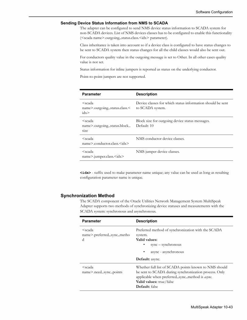
Software Configuration
Sending Device Status Information from NMS to SCADAThe adapter can be configured to send NMS device status information to SCADA system for non-SCADA devices. List of NMS devices classes has to be configured to enable this functionality (<scada name>.outgoing_status.class.<idx> parameter).
Class inheritance is taken into account so if a device class is configured to have status changes to be sent to SCADA system then status changes for all the child classes would also be sent out.
For conductors quality value in the outgoing message is set to Other. In all other cases quality value is not set.
Status information for inline jumpers is reported as status on the underlying conductor.
Point-to-point jumpers are not supported.
Parameter Description
<scada name>.outgoing_status.class.<idx>
Device classes for which status information should be sent to SCADA system.
<scada name>.outgoing_status.block_size
Block size for outgoing device status messages.Default: 10
<scada name>.conductor.class.<idx>
NMS conductor device classes.
<scada name>.jumper.class.<idx>
NMS jumper device classes.
<idx> - suffix used to make parameter name unique; any value can be used as long as resulting configuration parameter name is unique.
Synchronization MethodThe SCADA component of the Oracle Utilities Network Management System MultiSpeak Adapter supports two methods of synchronizing device statuses and measurements with the SCADA system: synchronous and asynchronous.
Parameter Description
<scada name>.preferred_sync_method
Preferred method of synchronization with the SCADA system.Valid values:
• sync – synchronous
• async - asynchronous
Default: async.
<scada name>.need_sync_points
Whether full list of SCADA points known to NMS should be sent to SCADA during synchronization process. Only applicable when preferred_sync_method is async.Valid values: true/falseDefault: false
MultiSpeak Adapter 10-43
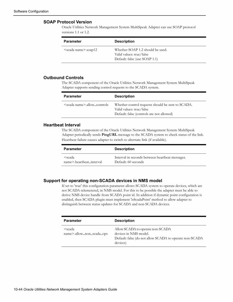
Software Configuration
SOAP Protocol VersionOracle Utilities Network Management System MultiSpeak Adapter can use SOAP protocol versions 1.1 or 1.2.
Parameter Description
<scada name>.soap12 Whether SOAP 1.2 should be used.Valid values: true/falseDefault: false (use SOAP 1.1)
Outbound ControlsThe SCADA component of the Oracle Utilities Network Management System MultiSpeak Adapter supports sending control requests to the SCADA system.
Parameter Description
<scada name>.allow_controls Whether control requests should be sent to SCADA.Valid values: true/falseDefault: false (controls are not allowed)
Heartbeat IntervalThe SCADA component of the Oracle Utilities Network Management System MultiSpeak Adapter periodically sends PingURL message to the SCADA system to check status of the link. Heartbeat failure causes adapter to switch to alternate link (if available).
Parameter Description
<scada name>.heartbeat_interval
Interval in seconds between heartbeat messages.Default: 60 seconds
Support for operating non-SCADA devices in NMS modelIf set to 'true' this configuration parameter allows SCADA system to operate devices, which are not SCADA-telemetered, in NMS model. For this to be possible the adapter must be able to derive NMS device handle from SCADA point id. In addition if dynamic point configuration is enabled, then SCADA plugin must implement 'isScadaPoint' method to allow adapter to distinguish between status updates for SCADA and non-SCADA devices.
Parameter Description
<scada name>.allow_non_scada_ops
Allow SCADA to operate non-SCADA devices in NMS model. Default: false (do not allow SCADA to operate non-SCADA devices)
10-44 Oracle Utilities Network Management System Adapters Guide

Software Configuration
Own Web Service URLThere are cases when the SCADA component of the Oracle Utilities Network Management System MultiSpeak Adapter needs to send an URL of its own web service to the SCADA system. For example, when sending asynchronous request to the SCADA system, it needs to provide a URL where the response should be sent when the results become available.
Parameter Description
<scada name>.OA.url URL where the incoming web service of the Oracle Utilities Network Management System MultiSpeak Adapter is deployed.
SCADA_IDSThis database table is used to configure the list of SCADA systems that the adapter will be communicating with. For SCADA systems compatible with this adapter, the column ADAPTER_TYPE should have value MULTISPEAK.
Example
INSERT INTO scada_ids (id, scada_name, adapter_type, active)VALUES (200, 'SCADA1', 'MULTISPEAK', 'Y');
INSERT INTO scada_ids (id, scada_name, adapter_type, active)VALUES (201, 'SCADA2', 'MULTISPEAK', 'Y');
SCADA_LINKSThis database table is used to configure communication links to the SCADA systems. It is allowed to configure multiple links to a single SCADA system. If one link fails the adapter will switch to another one in the order determined by the PRIORITY field (only one link is active at any given time). HTTPS and JMS links are supported.
• For HTTP links, the WS_URL column is used to specify the URL of the SCADA system web service.
• For JMS links, the columns REQUEST_QUEUE and RESPONSE_QUEUE are used to specify the JNDI names of the JMS queues used to send requests to and receive responses from the SCADA system.
• The value in the TIMEOUT column controls how long the adapter should wait for a response from the SCADA system (in seconds). This is only applicable to JMS links. The maximum allowed value is 3600 (1 hour).
• The value in the PERSISTENT column defines the delivery mode for JMS messages. If set to 'Y' then JMS messages are persistent, otherwise they are not persistent. By default messages are not persistent. This is only applicable to JMS links.
Example
INSERT INTO scada_links (id, scada_id, ws_url, timeout, priority, active)VALUES (1, 200, 'http://scada-server1:8088/SCADA', 30, 1, 'Y');INSERT INTO scada_links (id, scada_id, ws_url, timeout, priority, active)VALUES (2, 200, 'http://scada-server2:8088/SCADA', 30, 2, 'Y');INSERT INTO scada_links (id, scada_id, request_queue, response_queue, timeout, persistent, priority, active)VALUES (3, 200, 'queue/ScadaRequest', 'queue/ScadaResponse', 30, 'N', 3, 'Y');
MultiSpeak Adapter 10-45

Software Configuration
SCADA_LINK_OPSThis table can be used to configure JMS transport differently for individual outgoing web service operations. If an operation does not have a record in the SCADA_LINK_OPS table then values from the parent SCADA_LINKS record are used.
Column LINK_ID is the foreign key into the SCADA_LINKS table.
Column OPERATION is used to specify web service operation name. Supported operation names:
• PingURL
• GetMethods
• InitiateAnalogReadByPointID
• InitiateStatusReadByPointID
• InitiateTagReadByPointID
• InitiateControl
• GetAllSCADAAnalogs
• GetAllSCADAStatus
• GetAllSCADATags
• SCADAStatusChangedNotification
• SCADAStatusChangedNotificationByPointID
• StatusChangedNotificationByPointID
• HighlightObjectInDisplay
Columns REQUEST_QUEUE and RESPONSE_QUEUE are used to specify JNDI names of JMS queues used to send requests to and receive responses from SCADA system.
Value in the TIMEOUT column controls how long the adapter should wait for response from SCADA system (in seconds). Maximum allowed value is 3600 (1 hour).
Value in the PERSISTENT column defines delivery mode for JMS messages. If set to 'Y' then JMS messages are persistent, otherwise they are not persistent. By default messages are not persistent.
Example
INSERT INTO scada_link_ops (id, link_id, operation, request_queue, response_queue, timeout, persistent)VALUES (31, 3, 'PingURL', 'queue/ScadaRequest_PingURL', 'queue/ScadaResponse_PingURL', 30, 'N');
10-46 Oracle Utilities Network Management System Adapters Guide

Software Configuration
SCADA_SYNONYMSThis database table is used configure mapping of different data elements between SCADA and NMS systems. The SCADA_ID column should always be populated with the id of the SCADA system (value of the ID column in the SCADA_IDS table) the mapping applies to.
Device Status MappingBy default the adapter maps MultiSpeak device status values 'Open' and 'Closed' to the corresponding device statuses in NMS and ignores all other device status values defined by MultiSpeak 4.1 specification. SCADA_SYNONYMS table allows customization of device status mapping by associating MultiSpeak device status value to a combination of NMS device status and quality code.
The MultiSpeak device status value should be entered into the KEYWORD column. The NMS device status value should be entered into the STATUS_VALUE column. Valid values are 'Open', 'Closed' or NULL.
If this column is NULL, the device status in NMS will not be affected.
The NMS quality code should be entered in the INT_VALUE column. It will be combined with the quality code received in the MultiSpeak message. The PROCESS_TYPE should be 'S'.
The following example maps the 'Travel' device status received from SCADA to quality code 8192 and keeps device status in NMS unchanged.
INSERT INTO scada_synonyms (id, scada_id, keyword, status_value, int_value, process_type)VALUES (tmp_seq.nextval, 200, 'Travel', null, 262144, 'S');
Attribute MappingAttribute mapping is used when SCADA point ID does not uniquely identify both NMS device and attribute. SCADA attribute name/key should be entered into the KEYWORD column. NMS attribute key should be entered into the INT_VALUE column. PROCESS_TYPE should be 'D' for digital measurements and 'A' for analogs.
Example
INSERT INTO scada_synonyms (id, scada_id, keyword, int_value, process_type)VALUES (1, 200, 'faultIndicator', 23, 'D');INSERT INTO scada_synonyms (id, scada_id, keyword, int_value, process_type)VALUES (2, 200, 'Amps', 1012, 'A');
An additional method for configuring mapping for digital measurements is available. It applies specifically to the case when digital measurement is submitted to NMS via SCADAStatusChangedNotification, SCADAStatusChangedNotificationByPointID or StatusChangedNotificationByPointID operation. This is only possible when SCADA point id uniquely identifies digital measurement in NMS.
SCADA attribute name/key should be entered into the KEYWORD column.
NMS attribute name should be entered into ATTRIBUTE_ALIAS column.
Status value received from SCADA should be entered into STATUS_VALUE column.
Corresponding NMS attribute value should be entered into INT_VALUE column.
PROCESS_TYPE should be 'D'.
Column VALUE is not used.
MultiSpeak Adapter 10-47
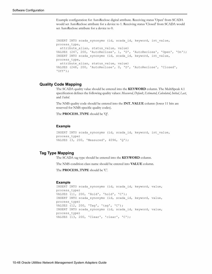
Software Configuration
Example configuration for AutoReclose digital attribute. Receiving status 'Open' from SCADA would set AutoReclose attribute for a device to 1. Receiving status 'Closed' from SCADA would set AutoReclose attribute for a device to 0.
INSERT INTO scada_synonyms (id, scada_id, keyword, int_value, process_type, attribute_alias, status_value, value)VALUES (247, 200, 'AutoReclose', 1, 'D', 'AutoReclose', 'Open', 'On');INSERT INTO scada_synonyms (id, scada_id, keyword, int_value, process_type, attribute_alias, status_value, value)VALUES (248, 200, 'AutoReclose', 0, 'D', 'AutoReclose', 'Closed', 'Off');
Quality Code MappingThe SCADA quality value should be entered into the KEYWORD column. The MultiSpeak 4.1 specification defines the following quality values: Measured, Default, Estimated, Calculated, Initial, Last, and Failed.
The NMS quality code should be entered into the INT_VALUE column (lower 11 bits are reserved for NMS-specific quality codes).
The PROCESS_TYPE should be 'Q'.
Example
INSERT INTO scada_synonyms (id, scada_id, keyword, int_value, process_type)VALUES (3, 200, 'Measured', 4096, 'Q');
Tag Type MappingThe SCADA tag type should be entered into the KEYWORD column.
The NMS condition class name should be entered into VALUE column.
The PROCESS_TYPE should be 'C'.
ExampleINSERT INTO scada_synonyms (id, scada_id, keyword, value, process_type)VALUES (11, 200, 'Hold', 'hold', 'C');INSERT INTO scada_synonyms (id, scada_id, keyword, value, process_type)VALUES (12, 200, 'Tag', 'tag', 'C');INSERT INTO scada_synonyms (id, scada_id, keyword, value, process_type)VALUES (13, 200, 'Clear', 'clear', 'C');
10-48 Oracle Utilities Network Management System Adapters Guide

Plugin Support
DDService Configuration for Outbound ControlsThe SCADA component of the Oracle Utilities Network Management System MultiSpeak Adapter periodically polls the database table EXPECTED_ACTIONS for pending SCADA controls.
DDService only write records into this table when it is running with the '-sendAsyncSCADA' command-line option.
SCADA Point ConfigurationThe SCADA component of the Oracle Utilities Network Management System MultiSpeak Adapter loads SCADA point configuration from the ANALOG_MEASUREMENTS and DIGITAL_MEASUREMENTS database tables. It normally happens during initialization. The adapter can be forced to reload the SCADA point configuration during runtime using the following command:
Action -java multispeak.SCADA reload
The synchronization sequence will be automatically started after the SCADA point configuration is reloaded.
Plugin SupportSCADA vendors may interpret MultiSpeak specification differently or use extensions, which are unique to each vendor. To address the issue of possible differences between various SCADA components, the NMS MultiSpeak adapter has a plugin interface.
Plugin is a Java class, which encapsulates functionality specific to a particular SCADA system. Plugin class must implement the interface com.splwg.oms.interfaces.scada.ScadaSystemPlugin.
Default implementation of the SCADA system plugin is provided by the com.splwg.oms.interfaces.scada.plugins.GenericScada class.
MethodsThe available plugin methods, including description of how the default plugin class implements each method, are:
getScadaPointIdjava.lang.String getScadaPointId(MspObject obj)
This method is used to extract SCADA Point ID from the incoming MultiSpeak message.
Parameters:
obj - MultiSpeak object
Returns:
SCADA Point ID
Default implementation:
Returns value of the objectID attribute if not empty, otherwise value of the objectName element
MultiSpeak Adapter 10-49

Plugin Support
getScadaPointIdjava.lang.String getScadaPointId(ScadaTag tag)
This method is used to extract SCADA Point ID from the incoming tag-related MultiSpeak message.
Parameters:
tag - ScadaTag object
Returns:
SCADA Point ID
Default implementation:
Returns value of the scadaPointID element
getStatusStatusIdentifiers getStatus(final ScadaStatus status);
This method is used to extract device status value from the MultiSpeak device status update message.
Parameters:
status - ScadaStatus object
Returns:
MultiSpeak device status value
Default implementation:
Returns value of the status element.
getQualityCodesjava.util.List<java.lang.String> getQualityCodes(ScadaStatus status)
This method is used to extract quality values from MultiSpeak status update message.
Parameters:
status - ScadaStatus object
Returns:
list of MultiSpeak quality values
Default implementation:
Returns value of the quality element
getQualityCodesjava.util.List<java.lang.String> getQualityCodes(ScadaAnalog analog)
This method is used to extract quality values from MultiSpeak analog update message.
Parameters:
analog - ScadaAnalog object
Returns:
list of MultiSpeak quality values
Default implementation:
Returns value of the quality element
10-50 Oracle Utilities Network Management System Adapters Guide

Plugin Support
processChangeCounterint processChangeCounter(StatusPoint point, int changeCounter)
This method is used to process SCADA change counter value.
Parameters:
point - SCADA status point
changeCounter - new change counter value for the SCADA status point
Returns:
Number of device operations, which occurred since the last processed update
Default implementation:
Assumes that change counter value received from SCADA is cumulative (total number of times device has changed state since some point in the past). Number of device operations is calculated as the difference between previous and current SCADA change counter values
getTagIdjava.lang.String getTagId(ScadaTag tag)
This method is used to extract value from the tag update message, which is then used to populate external id of the corresponding condition in NMS. This value has to uniquely identify the tag in NMS.
Parameters:
tag - ScadaTag object
Returns:
SCADA tag id
Default implementation:
Returns value of the objectID attribute
setTagIdvoid setTagId(ScadaTag tag, java.lang.String tagId)
This method is used during synchronization process to set tag id value in the tag update message, which is later extracted by the getTagId method.
Parameters:
tag - ScadaTag object to be updated
tagId - SCADA tag id
Default implementation:
Sets value of objectID attribute
MultiSpeak Adapter 10-51

Plugin Support
getTagTypejava.lang.String getTagType(ScadaTag tag)
This method is used to extract SCADA tag type from tag update message. This value is then used to determine corresponding NMS condition class.
Parameters:
tag - ScadaTag object
Returns:
SCADA tag type
Default implementation:
Returns value of the tagType element
getTagDatajava.util.Map<java.lang.String,java.lang.Object> getTagData(ScadaTag tag)
This method is used to extract additional tag data fields from tag message.
Parameters:
tag - ScadaTag object
Returns:
Map <tag field name -> tag field value>
Default implementation:
Returns map with a single entry ('text', value of the tagReason element)
getUserNamejava.lang.String getUserName(ScadaTag tag)
Extracts operator username from tag update message.
Parameters:
tag - ScadaTag object
Returns:
SCADA operator username
Default implementation:
Returns value of the userName element
getActionAction getAction(ScadaTag tag)
This method is used to extract action from tag update message. Action determines if the request is to place a new tag, update an existing tag or remove an existing tag.
Parameters:
tag - ScadaTag object
Returns:
action
• NEW - add new tag
10-52 Oracle Utilities Network Management System Adapters Guide

Plugin Support
• CHANGE - update an existing tag
• DELETE - delete an existing tag
Default implementation:
Returns value of the verb attribute
setActionvoid setAction(ScadaTag tag, Action action)
This method is used during synchronization process to set action value in the tag update message, which is later extracted by the getAction method.
Parameters:
tag - ScadaTag object to be updated
action - action
• NEW - add new tag
• CHANGE - update an existing tag
• DELETE - delete an existing tag
Default implementation:
Sets value of the verb attribute
buildScadaPointIdjava.lang.String buildScadaPointId(com.splwg.oms.common.intersys.Handle nmsDeviceHandle, java.lang.String nmsDeviceAlias, int phase) throws java.lang.IllegalArgumentException
This method is used to construct SCADA point id for status of an NMS device.
Parameters:
nmsDeviceHandle - NMS device handle
nmsDeviceAlias - NMS device alias
phase - phase
Returns:
SCADA point id or null if not supported
Throws:
java.lang.IllegalArgumentException - SCADA point id cannot be constructed for the given arguments
Default implementation:
Returns null
MultiSpeak Adapter 10-53

Plugin Support
parseScadaPointIdParsedSCADAPointId parseScadaPointId(java.lang.String scadaPointId)throws java.lang.IllegalArgumentException
Parse SCADA point id.
Parameters:
scadaPointId - SCADA point id
Returns:
ParsedSCADAPountId object
Throws:
java.lang.IllegalArgumentException - if scadaPointId cannot be parsed
Default implementation:
Populates NMS device id in ParsedSCADAPointId with scadaPointId argument.
generateControlScadaControl generateControl(ExpectedAction action)
This method is used to create ScadaControl object based on information from the EXPECTED_ACTIONS table.
Parameters:
action - row from EXPECTED_ACTIONS table
Returns:
ScadaControl object or null is controls are not supported
Default implementation:
Returns null
isScadaPointboolean isScadaPoint(final MspObject obj)
This method is used to determine if obj is a SCADA-telemetered point. Currently this method gets invoked only for status points.
Parameters:
obj - MultiSpeak object
Returns:
true if obj is a SCADA-telemetered point, otherwise false
Default implementation:
Returns true
10-54 Oracle Utilities Network Management System Adapters Guide

Plugin Support
Building Custom SCADA Plugins
Prerequisites• NMS is installed.
• nms-install-config --java script has been executed and nms-multispeak.ear file exists in the $NMS_HOME/java/deploy directory.
Steps1. Unpack $CES_HOME/sdk/java/samples/nms-multispeak-plugins.zip archive
into desired location (this location will be referred as PLUGIN_HOME). It includes Java project directory structure including example of plugin class and Ant build files.
2. Create Java class implementing com.splwg.oms.interfaces.scada.ScadaSystemPlugin interface and place it into desired location under PLUGIN_HOME/NmsScadaPlugin/src directory.
3. Execute following command to compile plugin class(s), build jar file and incorporate the jar file into the nms-multispeak.ear file.
ant -Dplatforms.JDK_1.6.home=<JDK home> clean update-ear
where
<JDK home> is the location where Java Development Kit 1.6 or later is installed
4. Update configuration for the Oracle Utilities NMS MultiSpeak Adapter to use new plugin class (configuration property '<scada name>.plugin_class').
5. Updated nms-multispeak.ear file can now be deployed into WebLogic server.
MultiSpeak Adapter 10-55

High-Level Messages
High-Level MessagesSCADA component of the NMS MultiSpeak adapter responds to several high-level messages. High-level message can be sent using Action command-line utility.
Action -java multispeak.SCADA <message>
Following messages are supported:
• RELOADForces adapter to reload configuration for the SCADA component.
• RESYNC [statuses|analogs|tags] [<scada id>|<scada name>]Initiates synchronization sequence.If 'statuses', 'analogs' or 'tags' qualifier is present in the message then synchronization sequence is executed only for that particular data flow. Otherwise full synchronization sequence is executed.
If <scada id> or <scada name> is specified then synchronization sequence is executed only for the designated SCADA system. Otherwise synchronization sequence is executed for all SCADA systems the adapter is connected to.
• FOCUS <user> <device> [<display>] [<action>]Causes HighlightObjectInDisplay message to be sent to the SCADA system(s). This message is used for display integration between NMS and SCADA system. For example, NMS operator can select a SCADA device in NMS viewer and trigger action, which would cause the same device to be selected/highlighted on SCADA system's display.Parameters:
• <user> - username of SCADA operator
• <device> - NMS device handle
• <display> - SCADA display
• <action> - action to perform
10-56 Oracle Utilities Network Management System Adapters Guide

Troubleshooting
TroubleshootingNMS MultiSpeak Adapter uses Apache log4j library to log error, warning and debug messages. To enable debug output following lines should be added to the log4j configuration file used by the WebLogic Server where the Adapter is deployed.
<logger name="com.splwg.oms.interfaces"> <level value="DEBUG"/> </logger> <logger name="com.splwg.oms.ws.multispeak"> <level value="DEBUG"/> </logger> <logger name="MultiSpeak"> <level value="DEBUG"/> </logger>
For additional details about configuring log4j logging in WebLogic Server see Configure Log4j Logging Services section in the Oracle Utilities Network Management System Installation Guide.
At runtime debug output can be toggled by sending high-level message to the appropriate component of the Adapter.
Action -java multispeak.<component> DEBUG
where <component> is one of
• AMR - AMR/AMI component
• AVL - AVL component
• SCADA - SCADA component
MultiSpeak Adapter 10-57

Troubleshooting
10-58 Oracle Utilities Network Management System Adapters Guide

Index
SymbolsAVLInterface.properties 10-9callbackFeederTimeout 1-27defaultCallbackAgent 1-27IccpAdapter.prm 9-4MDS_ RELATION_FIELD 6-46SRS Rules Configuration 1-24AAggregation 6-13Alternate Names 6-25amqscnxc 5-11amqsgetc 5-11, 5-12amqsputc 5-11AMR Business Processes 10-13AMR_CU_METERS 10-20AMR_REQUEST_RESP 10-21AMR_REQUESTS 10-18AMR_RESPONSES 10-19AMRInterface.properties 10-6ANALOG_MEASUREMENTS 8-21
BBase Path 6-36
CCallback Requests 1-5Callback Responses 1-6callbackInterfaceEnabled 1-25Callbacks application data flows 1-2CES_GET 5-34CES_PUT 5-34Change Detection 6-26Code Mapping Tables 6-81Code Mapping Tables 6-46Configuration Documents 6-37Controls Table 9-13Crew Message Tags 5-31Crew Outage Status Changes 5-17crewActive 6-78Customer Message Tags 5-28Customer Outage History 5-15customerPhoneParentheses 1-26
DData Flows 5-14data flows 1-2Database Table Schema 1-30DIGITAL_MEASUREMENTS 8-22DML Examples 6-50DML Files 6-16DML Function Calls 6-70DML Reference 6-56
EESRI ArcGIS 9.x Adapter 3-1Event Object Fields 6-129External Objects 6-28
FFlags 6-24Functions 6-71
clearIncidents 6-95completeEvent 6-98confirmDeviceOutage 6-101confirmServiceOutage 6-102createPseudoRelation 6-106createPseudoRelationFromConfirmServiceOutage 6-107Crew Functions 6-71crew functions
activateCrew 6-77arriveCrew 6-75assignCrew 6-76availableCrew 6-77createCrew 6-71crewActive 6-78crewOnShift 6-79dispatchCrew 6-74findCrewByExternalKey 6-72findCrewByExtKeySubStr 6-73findCrewById 6-72findCrewByIdSubStr 6-73releaseCrews 6-78setCrewOnShift 6-79setVehicleId 6-80unassignCrew 6-76updateCrew 6-73
damageSetAddress 6-85
Index-1

damageSetComment1 6-91damageSetCrewId 6-84damageSetFeederName 6-85damageSetGrid 6-88damageSetLoadAffected 6-90damageSetLocation 6-89damageSetNcg 6-85damageSetOption1 6-91damageSetPhase 6-89damageSetReportTime 6-84damageSetSection 6-88damageSetText1 6-90damageSetText2 6-92damageSetTransformer 6-87damageSetType 6-92damageSetZoneName 6-87ert 6-99Event Manipulation 6-95eventIsActive 6-101findOrCreateDamage 6-83findRelation 6-105getCaseNotesForEvent 6-97lockForEventCreation 6-103logDebug 6-94logFatalError 6-94Logging Functions 6-93logLocalError 6-93picklistCompLog 6-104picklistInfoUpdTr 6-105readGenericField 6-99readIncidents 6-95Relation Functions 6-105requestRowAction 6-100requestRowActionAll 6-100restoreOutage 6-103saveDamageDetails 6-93setCaseNoteInfo 6-96setEventInfo 6-97setGenericField 6-98
GG/Electric Adapte 4-1Generic IVR Adapter 1-1Generic SCADA Adapter 8-1Generic WebSphere MQ Adapter 5-1Generic WebSphere MQ Mobile Adapter 6-1
HHigh Level Messages 9-9, 9-21High Priority Category Table 6-48
IICCP Adapter 9-1Incident Object Fields 6-133Incidents table 1-23Information Model 5-20Input Documents 6-13Input Element Arrays 6-29Intergraph G/Electric Adapter 4-1IVR Adapter 1-1
IVR Adapter Installation 1-7IVR data flows 1-2IVRAdapter command line options 1-9
LListener 6-9listener 5-10loadMapConfigTable 6-81loadMapTable 6-82
MmapTableCode 6-83mapTableStr 6-82MDS_ORDER 6-41MDS_ORDER_FIELD 6-42MDS_RELATION 6-45MDS_RELATION_EVENT 6-46Message Tags 5-28MQ Client 5-10MultiSpeak Adapter 10-1
NNMSDeviceID 9-11, 9-22
OOracle WebLogic Server 10-3Order Tables 6-41Outage Detection 10-13Outage Status 5-15Output Documents 6-12Output Documents 6-12
PPDO Verification 10-15Permanent Order Object Fields 6-135Permanent Relationship Object Fields 6-135pk_ccb.trouble_code_config 1-53pr_customer_event_details 1-60pr_trouble_callback_requests 1-57pr_trouble_callback_responses 1-58pr_trouble_calls 1-54Pseudo Relationships 6-41PSO Verification 10-14
QQ manager listener 5-10Quality Codes 9-8, 9-20Quality Rules Table 9-11, 9-23Queue Manager Listener Service 6-9Queue Manager 6-8Queue Specification 6-31Queues 5-32
RRDBMS configuration 8-4Restoration Verification 10-16Root Element 6-35RS Message Type Table 6-47
Index-2

RTI_STATUS 8-15RTI_SYN Database 8-14Run Time Errors 6-49
SSCADA Adapter 8-1SCADA Adapter Data Flows 8-10SCADA Measurement Entry 8-11SCADA_ID Database 8-14Server Connection Channel 6-9SmallWorld GIS Adapter 2-1SQL Query 5-16SQL Transactions 5-16SRS Output 5-21Stop Statement 6-37Stored Procedure Parameters 1-42streetXsectionOffset 1-28Synchronization Process 5-12
TTriggers 6-32Trouble Call Mapping Configuration 1-16Trouble Call Message Tags 5-28Trouble Call Performance 1-29Trouble Calls 1-3TROUBLE_CALLBACKS 1-37TROUBLE_CALLS Table Schema 1-30troubleCallCreate 1-13
UuseExternalCause 1-26
WWebSphere MQ Adapter 5-1WebSphere MQ Mobile Adapter 6-1WebSphere MQ Server 5-9
Index-3

Index-4