Embed Size (px)
Citation preview

Oracle Utilities Network Management SystemAdapters Guide
Release 2.4.0.1.1
F24367-01
October 2019

Oracle Utilities Network Management System Adapters Guide, Release 2.4.0.1.1
F24367-01
Copyright © 1991, 2019 Oracle and/or its affiliates. All rights reserved.
This software and related documentation are provided under a license agreement containing restrictions on use and disclosure and are protected by intellectual property laws. Except as expressly permitted in your license agreement or allowed by law, you may not use, copy, reproduce, translate, broadcast, modify, license, transmit, distribute, exhibit, perform, publish, or display any part, in any form, or by any means. Reverse engineering, disassembly, or decompilation of this software, unless required by law for interoperability, is prohibited.
The information contained herein is subject to change without notice and is not warranted to be error-free. If you find any errors, please report them to us in writing.
If this is software or related documentation that is delivered to the U.S. Government or anyone licensing it on behalf of the U.S. Government, then the following notice is applicable:
U.S. GOVERNMENT END USERS: Oracle programs, including any operating system, integrated software, any programs installed on the hardware, and/or documentation, delivered to U.S. Government end users are “commercial computer software” pursuant to the applicable Federal Acquisition Regulation and agency-specific supplemental regulations. As such, use, duplication, disclosure, modification, and adaptation of the programs, including any operating system, integrated software, any programs installed on the hardware, and/or documentation, shall be subject to license terms and license restrictions applicable to the programs. No other rights are granted to the U.S. Government.
This software or hardware is developed for general use in a variety of information management applications. It is not developed or intended for use in any inherently dangerous applications, including applications that may create a risk of personal injury. If you use this software or hardware in dangerous applications, then you shall be responsible to take all appropriate fail-safe, backup, redundancy, and other measures to ensure its safe use. Oracle Corporation and its affiliates disclaim any liability for any damages caused by use of this software or hardware in dangerous applications.
Oracle and Java are registered trademarks of Oracle and/or its affiliates. Other names may be trademarks of their respective owners.
Intel and Intel Xeon are trademarks or registered trademarks of Intel Corporation. All SPARC trademarks are used under license and are trademarks or registered trademarks of SPARC International, Inc. AMD, Opteron, the AMD logo, and the AMD Opteron logo are trademarks or registered trademarks of Advanced Micro Devices. UNIX is a registered trademark of The Open Group.
This software or hardware and documentation may provide access to or information about content, products, and services from third parties. Oracle Corporation and its affiliates are not responsible for and expressly disclaim all warranties of any kind with respect to third-party content, products, and services unless otherwise set forth in an applicable agreement between you and Oracle. Oracle Corporation and its affiliates will not be responsible for any loss, costs, or damages incurred due to your access to or use of third-party content, products, or services, except as set forth in an applicable agreement between you and Oracle.
.

ContentsPreface.............................................................................................................................................................. 1-11
Audience..................................................................................................................................................................................... 1-11Related Documents .................................................................................................................................................................. 1-11Conventions............................................................................................................................................................................... 1-11
Chapter 1Generic IVR Adapter ......................................................................................................................................... 1-1
Introduction................................................................................................................................................................................. 1-1Supported Application Data Flows.......................................................................................................................................... 1-2
IVR Data Flows with Oracle Utilities Network Management System........................................................................... 1-2CIS Data Flows with Oracle Utilities Network Management System............................................................................ 1-2Callbacks Application Data Flows with Oracle Utilities Network Management System............................................ 1-2
Interaction Diagram ................................................................................................................................................................... 1-3Data Flow Details ....................................................................................................................................................................... 1-4
Overview.................................................................................................................................................................................. 1-4Trouble Calls ........................................................................................................................................................................... 1-4Callback Requests ................................................................................................................................................................... 1-5Callback Request Notes ......................................................................................................................................................... 1-6Callback Responses ................................................................................................................................................................ 1-6
Adapter Installation .................................................................................................................................................................... 1-8Ensure that the Generic IVR Adapter is installed. ............................................................................................................ 1-8Setup the Generic IVR Adapter System Variables ............................................................................................................ 1-8Configure Adapter to run as NMS System Service ........................................................................................................... 1-9IVRAdapter Command Line Options................................................................................................................................. 1-9Load the Generic IVR Adapter Database Tables and Stored Procedures .................................................................. 1-14
Software Configuration............................................................................................................................................................ 1-15Overview................................................................................................................................................................................ 1-15Trouble Call Mapping Configuration ................................................................................................................................ 1-15Mapping to Customer-Defined Fields in Oracle Utilities Network Management System's INCIDENTS table.. 1-22
Trouble Callback Mapping Configuration ............................................................................................................................ 1-22SRS Rules Configuration ......................................................................................................................................................... 1-23
Map Customer-Defined Fields in the INCIDENTS Table ........................................................................................... 1-23callbackInterfaceEnabled SRS Rule ................................................................................................................................... 1-24useExternalCause SRS Rule ................................................................................................................................................ 1-25customerPhoneParentheses SRS Rule............................................................................................................................... 1-25defaultCallbackAgent SRS Rule.......................................................................................................................................... 1-26callbackFeederTimeout SRS Rule ...................................................................................................................................... 1-26streetXsectionOffset SRS Rule........................................................................................................................................... 1-27Generic IVR Adapter Trouble Call Performance............................................................................................................ 1-28Generic IVR Adapter Troubleshooting ............................................................................................................................ 1-28
Database Schema ...................................................................................................................................................................... 1-29Overview................................................................................................................................................................................ 1-29Database Table Schema....................................................................................................................................................... 1-29
3

4
Stored Procedure Parameters ............................................................................................................................................. 1-41SRSInput Testing Utility Command Line Options ......................................................................................................... 1-62
Terminology .............................................................................................................................................................................. 1-63
Chapter 2SmallWorld GIS Adapter Template .................................................................................................................. 2-1
Chapter 3ESRI ArcGIS Adapter ....................................................................................................................................... 3-1
Adapter Overview....................................................................................................................................................................... 3-1Adapter Documentation............................................................................................................................................................ 3-1
Chapter 4Intergraph G/Electric Adapter......................................................................................................................... 4-1
Adapter Overview....................................................................................................................................................................... 4-1Adapter Documentation............................................................................................................................................................ 4-1
Chapter 5Generic IBM MQ Mobile Adapter.................................................................................................................... 5-1
Introduction................................................................................................................................................................................. 5-1Overview Description............................................................................................................................................................ 5-1Terminology ............................................................................................................................................................................ 5-2
Functional Description .............................................................................................................................................................. 5-3Functional Requirements....................................................................................................................................................... 5-3Hardware and Software Requirements................................................................................................................................ 5-4Required Installed Software .................................................................................................................................................. 5-5
Adapter Installation .................................................................................................................................................................... 5-6Overview.................................................................................................................................................................................. 5-6Configure Queues for Required Data Flows...................................................................................................................... 5-8
Design Overview ........................................................................................................................................................................ 5-9Configuration Concepts......................................................................................................................................................... 5-9Integration with System Services........................................................................................................................................ 5-10Aggregation of Objects........................................................................................................................................................ 5-11Information Flows................................................................................................................................................................ 5-11Performance .......................................................................................................................................................................... 5-12High Level Messages............................................................................................................................................................ 5-13Information Models ............................................................................................................................................................. 5-13
Configuration ............................................................................................................................................................................ 5-14DML Files.............................................................................................................................................................................. 5-14Configuration Tables............................................................................................................................................................ 5-40Run Time Errors................................................................................................................................................................... 5-48DML Examples..................................................................................................................................................................... 5-49
DML Reference ........................................................................................................................................................................ 5-55Lexical Conventions............................................................................................................................................................. 5-55Basic Concepts ...................................................................................................................................................................... 5-57Order of Document Processing and Other Considerations .......................................................................................... 5-66Ordering of Incidents in the Incident Object .................................................................................................................. 5-67DML Function Calls ............................................................................................................................................................ 5-69List of Functions................................................................................................................................................................... 5-70
Event Object Fields................................................................................................................................................................ 5-147Incident Object Fields........................................................................................................................................................ 5-151Permanent Order Object Fields ....................................................................................................................................... 5-153Permanent Relationship Object Fields............................................................................................................................ 5-153
Chapter 6SCADA Measurements ..................................................................................................................................... 6-1
Introduction to scadapop .......................................................................................................................................................... 6-1

Configuration .............................................................................................................................................................................. 6-1RDBMS Configuration .......................................................................................................................................................... 6-1
Recaching Measurements .......................................................................................................................................................... 6-2Information Model ..................................................................................................................................................................... 6-3
Database Schema .................................................................................................................................................................... 6-3
Chapter 7Generic SCADA Adapter................................................................................................................................... 7-1
Introduction................................................................................................................................................................................. 7-1Generic SCADA Adapter Configuration ....................................................................................................... 7-2
RDBMS vs. File Mode........................................................................................................................................................... 7-2Configure Adapter to Run as an NMS System Service..................................................................................................... 7-2SRS_RULES Configuration for Generic SCADA Adapter............................................................................................. 7-3Command Line Options for Generic SCADA Adapter................................................................................................... 7-3Scripts Used by the Generic SCADA Adapter .................................................................................................................. 7-5CES_PARAMETERS Configuration.................................................................................................................................. 7-5
Measurement Configuration ..................................................................................................................................................... 7-6Using SCADAPOP ................................................................................................................................................................ 7-6
RDBMS Configuration ............................................................................................................................................................ 7-11Configuration/Execution Sequence ...................................................................................................................................... 7-13
File-Based (RTAdapter)....................................................................................................................................................... 7-13SCADA Data - File Input ................................................................................................................................................... 7-15RDBMS Table Polling (RTDBAdapter) ........................................................................................................................... 7-17
Information Model ................................................................................................................................................................... 7-18Database Schema .................................................................................................................................................................. 7-18
MultiSpeak Integration ............................................................................................................................... 7-33DataRaker Integration.............................................................................................................................................................. 7-33
Use Cases ............................................................................................................................................................................... 7-34
Chapter 8ICCP Adapter.................................................................................................................................................... 8-1
ICCP Adapter Overview ........................................................................................................................................................... 8-1LiveData ICCP Adapter Configuration................................................................................................................................... 8-2
Configuring the Adapter to Run as a System Service ....................................................................................................... 8-3Populating the NMS Measurements Tables ..................................................................................................................... 8-10Information Model - Database Schema ............................................................................................................................ 8-11
TMW ICCP Adapter Configuration ...................................................................................................................................... 8-14Configuring the Adapter to Run as a System Service ..................................................................................................... 8-14Populating the NMS Measurements Tables ..................................................................................................................... 8-25Information Model - Database Schema ............................................................................................................................ 8-26
Chapter 9Specific SCADA Adapters ................................................................................................................................. 9-1
OSI SCADA Adapter................................................................................................................................................................. 9-1General Configuration Parameters ...................................................................................................................................... 9-1Point List Configuration........................................................................................................................................................ 9-2Real-Time States/Values ....................................................................................................................................................... 9-3Tags........................................................................................................................................................................................... 9-4Controls.................................................................................................................................................................................... 9-4Simulation ................................................................................................................................................................................ 9-4Navigation................................................................................................................................................................................ 9-5
Chapter 10SCADA Calculation Engine............................................................................................................................. 10-1
Introduction.............................................................................................................................................................................. 10-1SCADA Calculation Engine Database Configuration ........................................................................................................ 10-1
Examples................................................................................................................................................................................ 10-2
5

6
SCADA Calculation Engine SRS Rules Configuration....................................................................................................... 10-2
Chapter 11MultiSpeak Adapter ......................................................................................................................................... 11-1
Introduction............................................................................................................................................................................... 11-1Installation ................................................................................................................................................................................. 11-2
Installation Overview........................................................................................................................................................... 11-2Adapter Installation Instructions for Oracle WebLogic Server .................................................................................... 11-3JMS Transport Mechanism ................................................................................................................................................. 11-5
Software Configuration............................................................................................................................................................ 11-8Support for Encrypted Configuration Parameters .......................................................................................................... 11-8AMR Configuration Parameters......................................................................................................................................... 11-8Overriding Configuration Parameters ............................................................................................................................. 11-17Storing Meter Readings in AMR_RESPONSES Table................................................................................................ 11-18AVL Configuration Parameters........................................................................................................................................ 11-19Credentials Files .................................................................................................................................................................. 11-20Oracle Utilities Network Management System Configuration Rules ......................................................................... 11-21
Adapter Interface Communication Overview.................................................................................................................... 11-23Adapter Design ....................................................................................................................................................................... 11-25
Supported Data Flows ....................................................................................................................................................... 11-25AMR Business Processes................................................................................................................................................... 11-26
Database Schema .................................................................................................................................................................... 11-33AMR_REQUESTS ............................................................................................................................................................ 11-33AMR_RESPONSES .......................................................................................................................................................... 11-34AMR_CU_METERS ......................................................................................................................................................... 11-36AMR_CU_METERS_HISTORY ................................................................................................................................... 11-36AMR_VOLTAGE_HISTORY........................................................................................................................................ 11-37
SCADA Component .............................................................................................................................................................. 11-37JMS Transport Mechanism ............................................................................................................................................... 11-38Configuring JMS Support.................................................................................................................................................. 11-39
]Supported Data Flows .......................................................................................................................................................... 11-40NMS to SCADA................................................................................................................................................................. 11-40SCADA to NMS................................................................................................................................................................. 11-49
Software Configuration.......................................................................................................................................................... 11-57CES_PARAMETERS........................................................................................................................................................ 11-57
Plugin Support......................................................................................................................................................................... 11-70Methods................................................................................................................................................................................ 11-70Building Custom SCADA Plug-ins.................................................................................................................................. 11-78
High-Level Messages.............................................................................................................................................................. 11-79Troubleshooting...................................................................................................................................................................... 11-81
Chapter 12Mobile Workforce Management Adapter ........................................................................................................ 12-1
Introduction............................................................................................................................................................................... 12-1Installation ................................................................................................................................................................................. 12-2
Adapter Installation Instructions for Oracle WebLogic Server .................................................................................... 12-2Database Schema ...................................................................................................................................................................... 12-5
OMS_MWM_EVENTS...................................................................................................................................................... 12-5OMS_MWM_ACTIVITIES............................................................................................................................................... 12-6OMS_MWM_ALARMS...................................................................................................................................................... 12-7OMS_MWM_CREW_ACTIONS..................................................................................................................................... 12-7
Supported Data Flows ............................................................................................................................................................. 12-8Outgoing Flows .................................................................................................................................................................... 12-8Incoming Flows .................................................................................................................................................................... 12-9
Software Configuration.......................................................................................................................................................... 12-10Support for Encrypted Configuration Parameters ........................................................................................................ 12-10

Configuration Parameters.................................................................................................................................................. 12-11Oracle Utilities Network Management System Configuration Rules ......................................................................... 12-15
High-Level Messages.............................................................................................................................................................. 12-21Troubleshooting...................................................................................................................................................................... 12-21
Chapter 13SOAP Web Services.......................................................................................................................................... 13-1
Authentication........................................................................................................................................................................... 13-1Trouble Management Web Service........................................................................................................................................ 13-2
Port TroubleServiceSOAP .................................................................................................................................................. 13-2Switching and Safety Web Service ......................................................................................................................................... 13-5
Port SwmanServiceBeanPort ............................................................................................................................................. 13-5Damage Assessment Web Service........................................................................................................................................ 13-16
Port DamageServiceSOAP .............................................................................................................................................. 13-16
Chapter 14REST API ........................................................................................................................................................ 14-1
Authentication........................................................................................................................................................................... 14-1Resources ................................................................................................................................................................................... 14-2
GET /dmg-rest/reports...................................................................................................................................................... 14-4POST /dmg-rest/reports .................................................................................................................................................... 14-5GET /dmg-rest/reports/{id}............................................................................................................................................ 14-5POST /dmg-rest/reports/{id} .......................................................................................................................................... 14-6GET /dmg-rest/reports/{id}/attachments/{att_id} ................................................................................................... 14-6PUT /dmg-rest/reports/{id}/attachments/{att_id} .................................................................................................... 14-7DELETE /dmg-rest/reports/{id}/attachments/{att_id}........................................................................................... 14-8GET /dmg-rest/reports/required-parts........................................................................................................................... 14-8GET /dmg-rest/reports/config/{cfg} ............................................................................................................................ 14-9GET /mobile/attachments/{report-type}/{report-id}/{attachment-id}............................................................... 14-10PUT /mobile/attachments/{report-type}/{report-id}/{attachment-id} ............................................................... 14-11DELETE /mobile/attachments/{report-type}/{report-id}/{attachment-id} ...................................................... 14-11GET /mobile/control-zones............................................................................................................................................ 14-12GET /mobile/dataset/{table}......................................................................................................................................... 14-13PUT /mobile/dataset/{table} ......................................................................................................................................... 14-14GET /mobile/feeders ....................................................................................................................................................... 14-15GET /mobile/confirm-services/{handle} .................................................................................................................... 14-15PUT /mobile/confirm-services ....................................................................................................................................... 14-16GET /mobile/conditions ................................................................................................................................................. 14-17GET /mobile/conditions/device/{handle} ................................................................................................................. 14-18GET /mobile/conditions/{class}................................................................................................................................... 14-18POST /mobile/condition/{class} .................................................................................................................................. 14-18PUT /mobile/condition/{class}/{id}/{status} .......................................................................................................... 14-19GET /mobile/crews/{id}/availability ........................................................................................................................... 14-19POST /mobile/crews/{id}/availability ......................................................................................................................... 14-20GET /mobile/crews/{id}/status.................................................................................................................................... 14-20POST /mobile/crews/{id}/status.................................................................................................................................. 14-21GET /mobile/get-permissions ........................................................................................................................................ 14-22GET /mobile/mobile-user-validation ............................................................................................................................ 14-22GET /mobile/create-new-account.................................................................................................................................. 14-23GET /mobile/set-current-crew/{id} ............................................................................................................................. 14-23GET /mobile/damage-device-details ............................................................................................................................. 14-24PUT /mobile/device/assess............................................................................................................................................. 14-24PUT /mobile/device/unassess ........................................................................................................................................ 14-24GET /mobile/devices ....................................................................................................................................................... 14-25GET /mobile/crew-types ................................................................................................................................................. 14-25GET /mobile/maps........................................................................................................................................................... 14-26
7

8
GET /mobile/crews.......................................................................................................................................................... 14-26GET /mobile/crews/{id}................................................................................................................................................ 14-27GET /mobile/crews/user/{user id}.............................................................................................................................. 14-27GET /mobile/crews/{id}/assignments ........................................................................................................................ 14-28POST /mobile/crews/{id}/assignments/{event-id}/dispatch ................................................................................ 14-28POST /mobile/crews/{id}/assignments/{event-id}/onsite..................................................................................... 14-29POST /mobile/crews/{id}/assignments/{event-id}/undispatch............................................................................ 14-30POST /mobile/crews/{id}/assignments/{event-id}/assign..................................................................................... 14-31POST /mobile/crews/{id}/assignments/{event-id}/unassign ................................................................................ 14-32POST /mobile/crews/{id}/assignments/{event-id}/undispatch-and-assign........................................................ 14-33POST /mobile/crews/{id}/assignments/{event-id}/undispatch-and-assign-and-dispatch/{new-event-id} .. 14-34GET /trbl-rest/events/{id}............................................................................................................................................. 14-35PUT /trbl-rest/events/{id}/trouble-queue................................................................................................................... 14-36POST /trbl-rest/events/{id} ........................................................................................................................................... 14-37GET /trbl-rest/config/{cfg}........................................................................................................................................... 14-38GET /mobile/version ....................................................................................................................................................... 14-38GET /mobile/application-version/{name}/{arch}.................................................................................................... 14-39GET /mobile/application-versions/{name}/{arch} .................................................................................................. 14-39GET /mobile/application/{name}/{arch} .................................................................................................................. 14-40GET /mobile/application/{name}/{arch}/{version} .............................................................................................. 14-40POST /mobile/mobile-user-logout ................................................................................................................................ 14-41PUT /mobile/user-profile/{field-name}/{value} ....................................................................................................... 14-41GET /mobile/device/{id}/info ..................................................................................................................................... 14-42GET /mobile/device/{id}/operate/{operation}/phases/{phases}/time/{time}............................................... 14-43GET /mobile/device/{id}/lookahead/{operation}/{phases} ................................................................................ 14-44POST /mobile/device/statuses ....................................................................................................................................... 14-45GET /mobile/{id}/customers........................................................................................................................................ 14-45GET /mobile/maps/{mapname}................................................................................................................................... 14-46GET /mobile/file/:dir_name /:file_name..................................................................................................................... 14-46POST /mobile/crew.......................................................................................................................................................... 14-47GET /mobile/condition/{class}/{id} .......................................................................................................................... 14-47PUT /mobile/condition/{class}/{id}/text/{text}..................................................................................................... 14-48DELETE /mobile/condition/{class}/{id}.................................................................................................................. 14-49GET /mobile/switch-sheets/assignments/{crew-key} .............................................................................................. 14-49POST /mobile/switch-sheets/{sheet-class}/{sheet-index}/steps/{step-class}/{step-index}........................... 14-50POST /mobile/switch-sheets/{sheet-class}/{sheet-index}/steps/{step-class}/{step-index}/details ............. 14-51POST /mobile/switch-sheets/{sheet-class}/{sheet-index}/transition ................................................................... 14-52POST /mobile/switch-sheets/{sheet-class}/{sheet-index}/steps/{step-class}/{step-index}/location .......... 14-53GET /mobile/switch-sheets/{sheet-class}/{sheet-index}/report ........................................................................... 14-54GET /mobile/switch-sheets/{sheet-class}/{sheet-index}/document/{document-id}....................................... 14-55PUT /mobile/switch-sheets/{sheet-class}/{sheet-index}/document..................................................................... 14-56POST /mobile/hlm ........................................................................................................................................................... 14-57GET /mobile/lookup-types/{table}/{keyField}/{valueField}................................................................................ 14-58GET /mobile/nms-status ................................................................................................................................................. 14-59PUT /trbl-rest/event/{id}/confirm-outage.................................................................................................................. 14-60POST /trbl-rest/event/{id}/log ..................................................................................................................................... 14-61POST /trbl-rest/event/{id}/log-once ........................................................................................................................... 14-62POST /trbl-rest/event/{id}/state-transition ................................................................................................................ 14-62GET /trbl-rest/events/{id}/customers ........................................................................................................................ 14-63POST /trbl-rest/user-log .................................................................................................................................................. 14-64POST /trbl-rest/user-log-once ........................................................................................................................................ 14-64
Chapter 15Weather Data Adapter...................................................................................................................................... 15-1
Adapter Overview..................................................................................................................................................................... 15-1

Data Import Formats ............................................................................................................................................................... 15-2Flat CSV Files........................................................................................................................................................................ 15-2External Database Table .......................................................................................................................... 15-3NOAA Weather Service ...................................................................................................................................................... 15-4
Running the Adapter ................................................................................................................................................................ 15-5Related Runtime and Configuration Tables ......................................................................................................................... 15-6
Chapter 16DERMS Adapter .............................................................................................................................................. 16-1
Overview.................................................................................................................................................................................... 16-1Configuration ............................................................................................................................................................................ 16-1
PF_DERMS_ADAPTER_CONFIG ............................................................................................................................... 16-2Running the Adapter ................................................................................................................................................................ 16-3Database Tables ........................................................................................................................................................................ 16-4Log Files ..................................................................................................................................................................................... 16-5
Chapter 17Profile Adapter ................................................................................................................................................. 17-1
Adapter Overview..................................................................................................................................................................... 17-1PV Profile Creation .................................................................................................................................................................. 17-1Load Profile Creation............................................................................................................................................................... 17-2SRS Rule Configuration........................................................................................................................................................... 17-2Running the Adapter ................................................................................................................................................................ 17-3Load Profile File Format ......................................................................................................................................................... 17-5Error Handling.......................................................................................................................................................................... 17-6
9

10

Preface
Please read through this guide thoroughly before beginning an installation or configuration of any supported adapters for the Oracle Utilities Network Management System.
AudienceThis document is intended for administrators and engineers responsible for installing and configuring Oracle Utilities Network Management System adapters.
Related Documents• Oracle Utilities Network Management System Installation Guide
• Oracle Utilities Network Management System Licensing Information User Manual
• Oracle Utilities Network Management System Configuration Guide
• Oracle Utilities Network Management System Operations Mobile Application Installation and Deployment Guide
• Oracle Utilities Network Management System User’s Guide
• Oracle Utilities Network Management System OMS for Water User’s Guide
ConventionsThe following text conventions are used in this document:
Convention Meaning
boldface Boldface type indicates graphical user interface elements associated with an action, or terms defined in text or the glossary.
italic Italic type indicates book titles, emphasis, or placeholder variables for which you supply particular values.
monospace Monospace type indicates commands within a paragraph, URLs, code in examples, text that appears on the screen, or text that you enter.
11

12

Chapter 1Generic IVR Adapter
This chapter includes the following topics:
• Introduction
• Supported Application Data Flows
• Interaction Diagram
• Data Flow Details
• Adapter Installation
• Software Configuration
• SRS Rules Configuration
• Database Schema
• Terminology
IntroductionThis chapter is an administration guide for the Oracle Utilities Network Management System Generic Interactive Voice Response (IVR) System Adapter. This chapter describes the processes required to install and configure the adapter to run with various IVR applications. This adapter has the following attributes:
• It is one of the adapters and tools that Oracle offers for integration with other product suites. It is a Unix application that generally executes on the Oracle Utilities Network Management System services server and is monitored through SMService.
• It has the ability to accept trouble calls from an external application and provide that external application with updates about existing outages.
• It can submit callback requests to an external application and receive callback responses from the external application.
• It can communicate with several external applications, such as Interactive Voice Response (IVR) systems, Customer Information System (CIS) and Callback applications.
Generic IVR Adapter 1-1

Supported Application Data Flows
Supported Application Data Flows
IVR Data Flows with Oracle Utilities Network Management SystemThe following are the Data Flows between an IVR system and Oracle Utilities Network Management System using the Generic IVR Adapter
• Creation of trouble calls from the IVR system to Oracle Utilities Network Management System
• Callback request information from Oracle Utilities Network Management System to the IVR system
• Callback response information from the IVR system to Oracle Utilities Network Management System
CIS Data Flows with Oracle Utilities Network Management SystemThe following are the Data Flows between a CIS and Oracle Utilities Network Management System using the Generic IVR Adapter
• Creation of trouble calls from the CIS application to Oracle Utilities Network Management System
Callbacks Application Data Flows with Oracle Utilities Network Management System
The following are the Data Flows between a Callback application and Oracle Utilities Network Management System using the Generic IVR Adapter
• Callback request information from Oracle Utilities Network Management System to the Callback application
• Callback response information from Callback application to Oracle Utilities Network Management System
1-2 Oracle Utilities Network Management System Adapters Guide

Interaction Diagram
Interaction DiagramBelow is a diagram of the interaction between Oracle Utilities Network Management System and various external applications via the Generic IVR Adapter.
Note: In this document, it is assumed that the Generic IVR Adapter's tables and stored procedures would reside in the database used by Oracle Utilities Network Management System.
Generic IVR Adapter 1-3

Data Flow Details
Data Flow Details
OverviewThis section discusses in detail the data flows that are relevant to the Generic IVR Adapter. The data flows generally involve bilateral database tables that are populated or polled by the adapter or stored procedures that access internal NMS tables directly. The adapter data flows are turned on through command line switches, but the actual data transfer may be affected through the use of stored procedures.
Trouble CallsNew trouble calls need to be sent to Oracle Utilities Network Management System to apply the outage analysis algorithm to predict the outage device. The Generic IVR Adapter provides the submit_call stored procedure to pass trouble call information from the external application to Oracle Utilities Network Management System.
There are two PL/SQL packages available for interacting with the Generic IVR Adapter. Package pk_ivr_interface allows a full range of functionality provided by the adapter to be used. Package pk_ccb, which supports integration of NMS to Customer Information System (CIS), provides procedure for submitting trouble calls through Generic IVR Adapter.
Data Flow CharacteristicsThe following are characteristics of the Trouble Calls Data Flow
Data Flow Steps1. The external application invokes the submit_call stored procedure to submit a trouble call.
2. The submit_call stored procedure inserts the trouble call in the TROUBLE_CALLS table. Upon insertion, the TROUBLE_CALLS.CALL_STATUS field will be set to 'N' signifying a new trouble call.
3. The Generic IVR Adapter polls a configurable number of new records from the TROUBLE_CALLS table within a configurable poll period. The TROUBLE_CALLS.CALL_STATUS field is updated to 'I' (in progress) signifying that the trouble call is in the process of being submitted to the NMS Job Management Service (JMService).
Characteristics Value
Table TROUBLE_CALLS. For schema information, see TROUBLE_CALLS Table Schema on page 1-29.
Stored Procedures pk_ivr_interface.pr_trouble_calls and pk_ccb.submit_callFor stored procedure parameter information, see pk_ccb.submit_call on page 1-41 and pr_trouble_calls on page 1-53.
Direction external application to Oracle Utilities Network Management System
Generic IVR Adapter Data Retrieval Frequency to Oracle Utilities Network Management System
Periodic (configurable)
1-4 Oracle Utilities Network Management System Adapters Guide

Data Flow Details
4. Once processed, the retrieved records are submitted to NMS' JMService so the outage analysis algorithms could be used for the submitted trouble calls. The TROUBLE_CALLS.CALL_STATUS field is updated to 'C' (complete) signifying the trouble call has been successfully submitted from the external application to NMS.
Below is a summary of the information required to submit a trouble call via the pk_ccb.submit_call stored procedure.
If no numeric trouble code is provided, the default trouble code, which is generally a 1 followed by however many zeros are necessary to satisfy the project defined trouble code, will be used. The length of the trouble code is defined by the number of distinct "group_order" entries in the srs_trouble_codes table.
Note that the pr_trouble_calls stored procedure is also provided to accomplish essentially the same goal - inserting a trouble call record into the trouble_calls table.
The pk_ccb.submit_call stored procedure is used to submit:
• Trouble calls for a particular customer (known premise/service point). This includes entering the meeting time for job site appointments when there needs to be a planned outage to perform non-utility work at a location, such as tree removal near a power line or house painting.
• Fuzzy calls
When a fuzzy call is created at least one of the following call identifiers must be provided:
• The caller's name
• The caller's phone number
• The caller's ID (i.e., 911 reference ID provided by the caller (911)).
• Location must also be provided. A Location can be:
• a street intersection (provide two street names) or
• a street segment (provide a block number and a street name)
• City and State are optional
Callback RequestsA customer may request that he/she be called back as soon as the outage that he/she reported has been restored. The Generic IVR Adapter provides the stored procedure pr_trouble_callback_requests to be used by an external application that is managing the callback process. This procedure returns a list of calls where the customer has requested a callback.
Generic IVR Adapter 1-5

Data Flow Details
Data Flow CharacteristicsThe following are characteristics for the Callback Request Data Flow:
Data Flow Steps1. When an outage with a corresponding callback request is restored, Oracle Utilities Network
Management System builds a callback list.
2. From the list, callback requests could be assigned to callback agents or to the external application, either in a manual (using Oracle Utilities Network Management System Web Callbacks) or an automated manner (via SRS rules).
3. The Generic IVR Adapter retrieves all callback requests assigned to the external application and inserts the callback requests to the TROUBLE_CALLBACKS table. The PROCESS_STATUS field of the callback request in the table would be set to 'N' signifying that the callback request is new. The CALLBACK_DONE field of the callback request in the table would be set to 'N' signifying that the callback has not yet been done.
4. The Generic IVR Adapter provides the pr_trouble_callback_requests stored procedure, which picks new callback requests from the TROUBLE_CALLBACKS table.
5. The external application could use the pr_trouble_callback_requests stored procedure to pick new callback requests. Callback requests that were picked are marked with a PROCESS_STATUS field equal to ‘I’ (callback response in progress) on the TROUBLE_CALLBACKS table.
Callback Request NotesOnce an outage event or a non-outage event is restored, callbacks are generated if the call is marked for a callback. All events have a restoration, either explicit or implicit, so any event can generate a callback. Also, in the event that the customer called multiple times, the customer will receive multiple callbacks if he requested a callback on each call. JMService gathers every call associated with an event, without filtering duplicate callers. Every call that is marked for callback will receive a callback.
Callback ResponsesThe external application calls the customer to confirm if power has been restored or not. The result of this call is passed from the external application to Oracle Utilities Network Management System via the pr_trouble_callback_responses stored procedure.
Characteristics Value
Table TROUBLE_CALLBACKS. For schema information, see TROUBLE_CALLBACKS Table Schema on page 1-36.
Stored Procedure pr_trouble_callback_requests. For stored procedure parameter information, see pr_trouble_callback_requests on page 1-57
Direction Oracle Utilities Network Management System to external application
Generic IVR Adapter Data Retrieval Frequency from Oracle Utilities Network Management System
Periodic (configurable)
1-6 Oracle Utilities Network Management System Adapters Guide
Data Flow Details
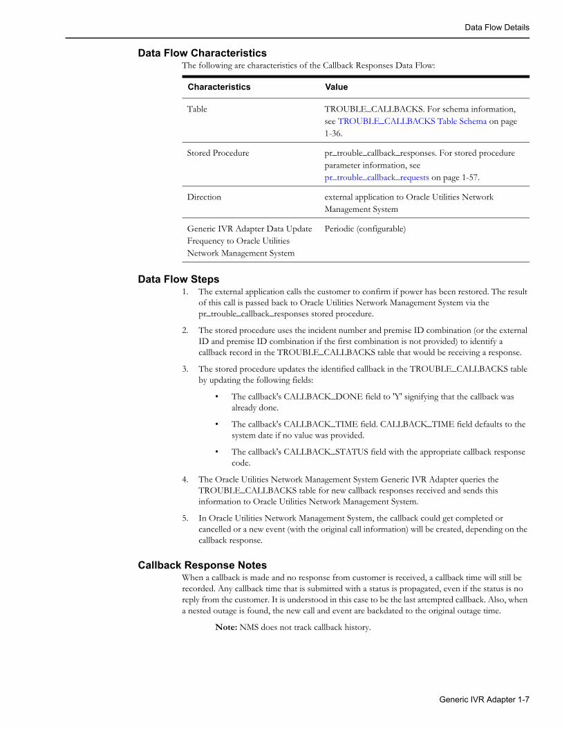
Data Flow CharacteristicsThe following are characteristics of the Callback Responses Data Flow:
Data Flow Steps1. The external application calls the customer to confirm if power has been restored. The result
of this call is passed back to Oracle Utilities Network Management System via the pr_trouble_callback_responses stored procedure.
2. The stored procedure uses the incident number and premise ID combination (or the external ID and premise ID combination if the first combination is not provided) to identify a callback record in the TROUBLE_CALLBACKS table that would be receiving a response.
3. The stored procedure updates the identified callback in the TROUBLE_CALLBACKS table by updating the following fields:
• The callback's CALLBACK_DONE field to 'Y' signifying that the callback was already done.
• The callback's CALLBACK_TIME field. CALLBACK_TIME field defaults to the system date if no value was provided.
• The callback's CALLBACK_STATUS field with the appropriate callback response code.
4. The Oracle Utilities Network Management System Generic IVR Adapter queries the TROUBLE_CALLBACKS table for new callback responses received and sends this information to Oracle Utilities Network Management System.
5. In Oracle Utilities Network Management System, the callback could get completed or cancelled or a new event (with the original call information) will be created, depending on the callback response.
Callback Response NotesWhen a callback is made and no response from customer is received, a callback time will still be recorded. Any callback time that is submitted with a status is propagated, even if the status is no reply from the customer. It is understood in this case to be the last attempted callback. Also, when a nested outage is found, the new call and event are backdated to the original outage time.
Note: NMS does not track callback history.
Characteristics Value
Table TROUBLE_CALLBACKS. For schema information, see TROUBLE_CALLBACKS Table Schema on page 1-36.
Stored Procedure pr_trouble_callback_responses. For stored procedure parameter information, see pr_trouble_callback_requests on page 1-57.
Direction external application to Oracle Utilities Network Management System
Generic IVR Adapter Data Update Frequency to Oracle Utilities Network Management System
Periodic (configurable)
Generic IVR Adapter 1-7

Adapter Installation
Adapter InstallationThis section describes how to install the Oracle Utilities Network Management System Generic IVR Adapter.
Ensure that the Generic IVR Adapter is installed.• Verify that the following files are found in their respective folders
• $CES_HOME/lib/libIVRAdapter.so
• $CES_HOME/bin/IVRAdapter
• $CES_HOME/bin/ces_ivr_gateway.ces
• $CES_HOME/sql/product_retain_ivr_interface.sql
• $CES_HOME/sql/product_ivr_interface_head.sql
• $CES_HOME/sql/product_ivr_interface_body.plb
• $CES_HOME/bin/troubleCallCreate
• $CES_HOME/bin/ivrCallPerPoll.ces
• $CES_HOME/bin/ivrPollPeriod.ces
Setup the Generic IVR Adapter System VariablesInclude the following variables in the system variables definition:
Note that this is setup in the .nmsrc file located in the $NMS_HOME (and configured by running config_nmsrc.pl). After the setup of the system variables, make sure that the .nmsrc is rerun or a new terminal is opened. The above setup assumes that the database where the Generic IVR Adapter tables and stored procedures would reside would be the same database used by the Oracle Utilities Network Management System environment.
Note also that the IVR RDBMS can be setup to be a completely separate RDBMS from the production RDBMS instance (hence these environment variables). This option may be considered if a project wants to maintain separation between the call taking process and the call processing process. With a separate RDBMS instance trouble calls can still be captured even if the production NMS RDBMS instance is down - for example. This is considered an advanced form of configuration and generally requires certain tables be replicated between the two RDBMS instances to guarantee calls can still be properly captured when the NMS RDBMS is down. Please consult Oracle support or your project engineer for more information if this type of configuration is desired.
Variable Value
IVR_RDBMS_HOST same as $RDBMS_HOST defined in the system
IVR_ORACLE_SID same as $ORACLE_SID defined in the system
1-8 Oracle Utilities Network Management System Adapters Guide
Adapter Installation
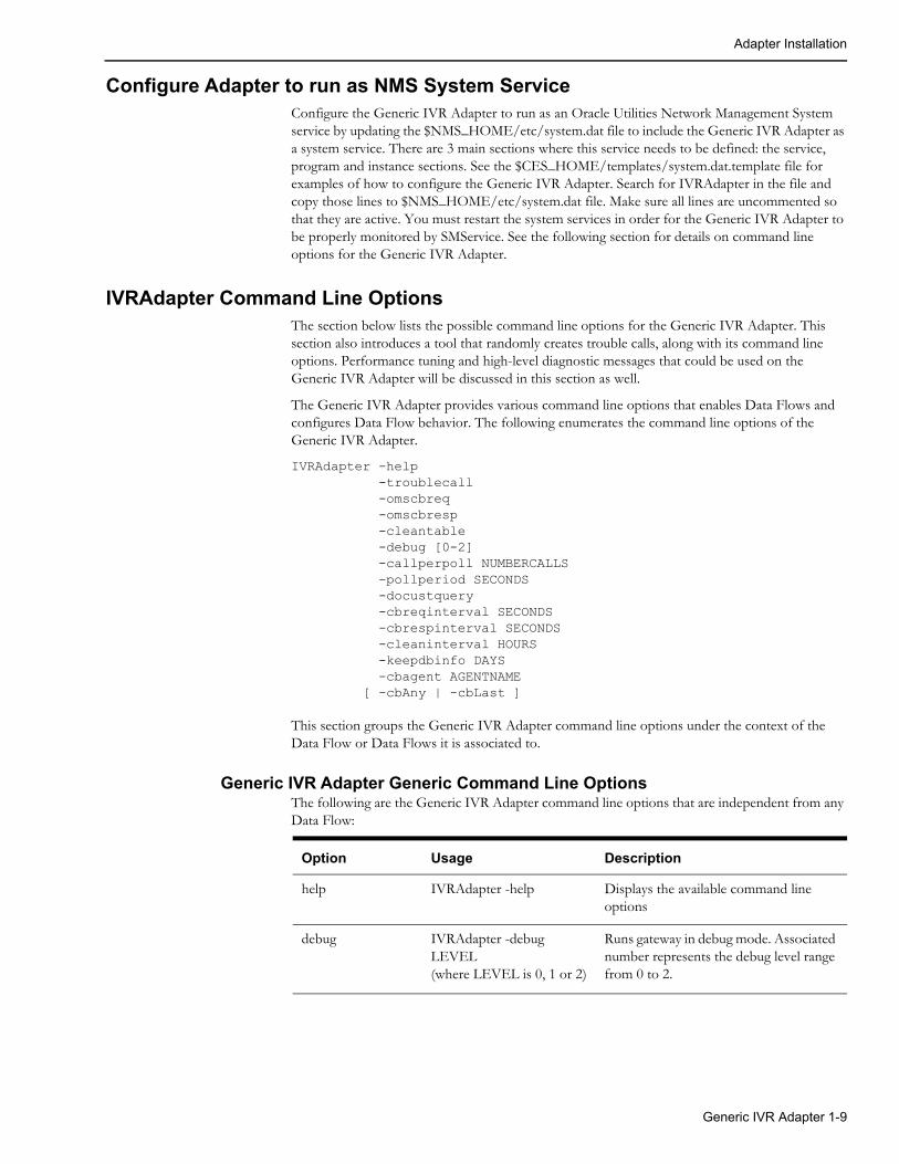
Configure Adapter to run as NMS System ServiceConfigure the Generic IVR Adapter to run as an Oracle Utilities Network Management System service by updating the $NMS_HOME/etc/system.dat file to include the Generic IVR Adapter as a system service. There are 3 main sections where this service needs to be defined: the service, program and instance sections. See the $CES_HOME/templates/system.dat.template file for examples of how to configure the Generic IVR Adapter. Search for IVRAdapter in the file and copy those lines to $NMS_HOME/etc/system.dat file. Make sure all lines are uncommented so that they are active. You must restart the system services in order for the Generic IVR Adapter to be properly monitored by SMService. See the following section for details on command line options for the Generic IVR Adapter.
IVRAdapter Command Line OptionsThe section below lists the possible command line options for the Generic IVR Adapter. This section also introduces a tool that randomly creates trouble calls, along with its command line options. Performance tuning and high-level diagnostic messages that could be used on the Generic IVR Adapter will be discussed in this section as well.
The Generic IVR Adapter provides various command line options that enables Data Flows and configures Data Flow behavior. The following enumerates the command line options of the Generic IVR Adapter.
IVRAdapter -help -troublecall -omscbreq -omscbresp -cleantable -debug [0-2] -callperpoll NUMBERCALLS -pollperiod SECONDS -docustquery -cbreqinterval SECONDS -cbrespinterval SECONDS -cleaninterval HOURS -keepdbinfo DAYS -cbagent AGENTNAME [ -cbAny | -cbLast ]
This section groups the Generic IVR Adapter command line options under the context of the Data Flow or Data Flows it is associated to.
Generic IVR Adapter Generic Command Line OptionsThe following are the Generic IVR Adapter command line options that are independent from any Data Flow:
Option Usage Description
help IVRAdapter -help Displays the available command line options
debug IVRAdapter -debug LEVEL(where LEVEL is 0, 1 or 2)
Runs gateway in debug mode. Associated number represents the debug level range from 0 to 2.
Generic IVR Adapter 1-9

Adapter Installation
Trouble Call Data Flow Command Line OptionsThe following are the Generic IVR Adapter command line options that are related to the Trouble Calls Data Flow. For more information, see Trouble Calls on page 1-4.
Option Usage DescriptionDepends On
Default Value
troublecall IVRAdapter -troublecall
Enables the Trouble Calls Data Flow.Note: This option must be enabled for CC&B - NMS integration.
callperpoll IVRAdapter -callperpoll NUMBERCALLS(where NUMBERCALLS is an integer)
Specifies the number of calls processed in the TROUBLE_CALLS table per poll of information.
troublecall 100 calls per poll of information
pollperiod IVRAdapter -pollperiod SECONDS(where SECONDS is an integer)
Specifies the interval (in seconds) between two successive polls or queries from the TROUBLE_CALLS table
troublecall a 6 second interval between two successive polls
docustquery IVRAdapter -docustquery
If this option is selected, not all fields in the TROUBLE_CALLS table are directly fed to JMService. Instead, some of the fields would come from the CES_CUSTOMERS table. Note: This option should not be used in combination with the CC&B - NMS integration.
troublecall
1-10 Oracle Utilities Network Management System Adapters Guide
Adapter Installation
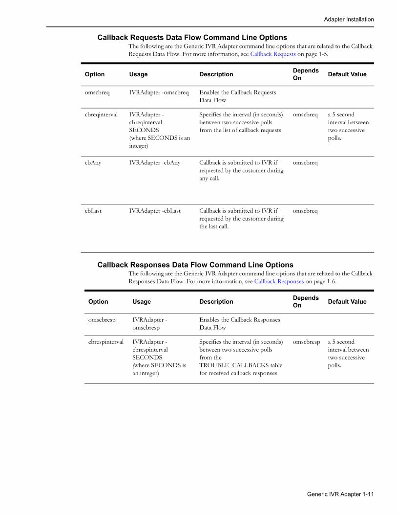
Callback Requests Data Flow Command Line OptionsThe following are the Generic IVR Adapter command line options that are related to the Callback Requests Data Flow. For more information, see Callback Requests on page 1-5.
Callback Responses Data Flow Command Line OptionsThe following are the Generic IVR Adapter command line options that are related to the Callback Responses Data Flow. For more information, see Callback Responses on page 1-6.
Option Usage DescriptionDepends On
Default Value
omscbreq IVRAdapter -omscbreq Enables the Callback Requests Data Flow
cbreqinterval IVRAdapter -cbreqinterval SECONDS(where SECONDS is an integer)
Specifies the interval (in seconds) between two successive polls from the list of callback requests
omscbreq a 5 second interval between two successive polls.
cbAny IVRAdapter -cbAny Callback is submitted to IVR if requested by the customer during any call.
omscbreq
cbLast IVRAdapter -cbLast Callback is submitted to IVR if requested by the customer during the last call.
omscbreq
Option Usage DescriptionDepends On
Default Value
omscbresp IVRAdapter -omscbresp
Enables the Callback Responses Data Flow
cbrespinterval IVRAdapter -cbrespinterval SECONDS(where SECONDS is an integer)
Specifies the interval (in seconds) between two successive polls from the TROUBLE_CALLBACKS table for received callback responses
omscbresp a 5 second interval between two successive polls.
Generic IVR Adapter 1-11

Adapter Installation
Command Line Options Used by Multiple Data FlowsThe following are the Generic IVR Adapter command line options that are related to multiple Data Flows. On the ‘Depends On’ section, the term ‘any option that enables a Data Flow’ would pertain to either one of the following command line options: ‘troublecall’, ‘omscbreq’ and ‘omscbresp’.
For the keepdbinfo command line options, a record that starts aging on a given day, say 9:00 p.m. would be considered one day old at 9:00 p.m. the next day (and not 12:00 a.m., which is just 3 hours from the time the record started aging).
Option Usage DescriptionDepends On
Default Value
cleantable IVRAdapter -cleantable
Could be used for any of the five Data Flows. A flag that allows the Generic IVR Adapter to remove some completed records from its tables.
any option that enables a Data Flow
cleaninterval IVRAdapter -cleaninterval HOURS(where HOURS is an integer)
Could be used for any of the five Data Flows.Specifies the interval (in HOURS) between two successive attempts to delete old (i.e., completed) records from the Oracle Utilities Network Management System Generic IVR Adapter tables.
Cleantable and any option that enables a Data Flow
1 hour between to successive delete attempts
keepdbinfo IVRAdapter -keepdbinfo DAYS(where DAYS is an integer)
Could be used for any of the five Data Flows.Completed records on the Generic IVR Adapter tables older than the specified number of days will be deleted. Certain criteria apply on which records of the Oracle Utilities Network Management System Generic IVR Adapter tables are removed and how the records are aged.
Cleantable and any option that enables a Data Flow
3 days
cbagent IVRAdapter –cbagent AGENTNAME (where AGENTNAME is a string)
Could be used for the Callback Requests and Callback Responses Data Flows.The agent name that the Generic IVR Adapter uses in retrieving calls from the callback list. Valid agent names are located in CES_USER and ENV_ACCESS tables. The agent name used should be an external agent, as indicated in the CES_USER table.
omscbreq or omscbresp
IVR
1-12 Oracle Utilities Network Management System Adapters Guide
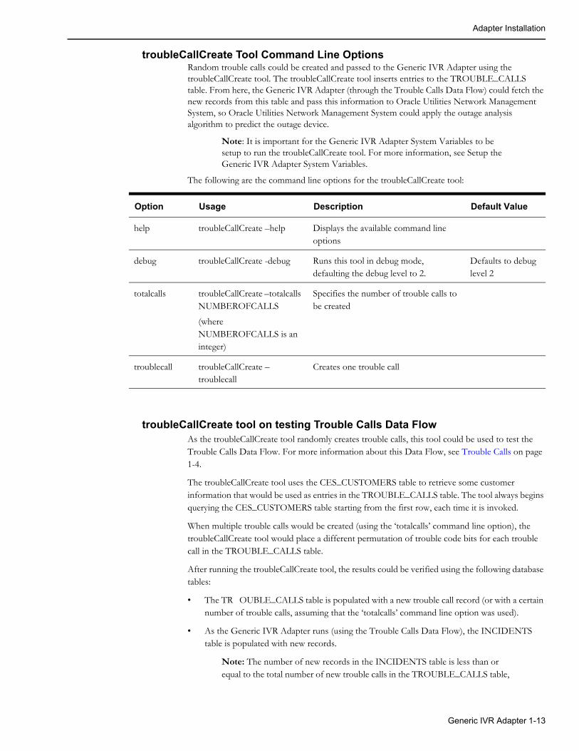
Adapter Installation
troubleCallCreate Tool Command Line OptionsRandom trouble calls could be created and passed to the Generic IVR Adapter using the troubleCallCreate tool. The troubleCallCreate tool inserts entries to the TROUBLE_CALLS table. From here, the Generic IVR Adapter (through the Trouble Calls Data Flow) could fetch the new records from this table and pass this information to Oracle Utilities Network Management System, so Oracle Utilities Network Management System could apply the outage analysis algorithm to predict the outage device.
Note: It is important for the Generic IVR Adapter System Variables to be setup to run the troubleCallCreate tool. For more information, see Setup the Generic IVR Adapter System Variables.
The following are the command line options for the troubleCallCreate tool:
troubleCallCreate tool on testing Trouble Calls Data FlowAs the troubleCallCreate tool randomly creates trouble calls, this tool could be used to test the Trouble Calls Data Flow. For more information about this Data Flow, see Trouble Calls on page 1-4.
The troubleCallCreate tool uses the CES_CUSTOMERS table to retrieve some customer information that would be used as entries in the TROUBLE_CALLS table. The tool always begins querying the CES_CUSTOMERS table starting from the first row, each time it is invoked.
When multiple trouble calls would be created (using the ‘totalcalls’ command line option), the troubleCallCreate tool would place a different permutation of trouble code bits for each trouble call in the TROUBLE_CALLS table.
After running the troubleCallCreate tool, the results could be verified using the following database tables:
• The TR OUBLE_CALLS table is populated with a new trouble call record (or with a certain number of trouble calls, assuming that the ‘totalcalls’ command line option was used).
• As the Generic IVR Adapter runs (using the Trouble Calls Data Flow), the INCIDENTS table is populated with new records.
Note: The number of new records in the INCIDENTS table is less than or equal to the total number of new trouble calls in the TROUBLE_CALLS table,
Option Usage Description Default Value
help troubleCallCreate –help Displays the available command line options
debug troubleCallCreate -debug Runs this tool in debug mode, defaulting the debug level to 2.
Defaults to debug level 2
totalcalls troubleCallCreate –totalcalls NUMBEROFCALLS
(where NUMBEROFCALLS is an integer)
Specifies the number of trouble calls to be created
troublecall troubleCallCreate –troublecall
Creates one trouble call
Generic IVR Adapter 1-13

Adapter Installation
as Oracle Utilities Network Management System outage analysis algorithms allow grouping of calls based on various criteria.
troubleCallCreate tool on testing Callback Requests Data FlowThe Callback Requests Data Flow could be tested as well using the troubleCallCreate tool, since all trouble calls generated by such tool requires callback. For more information about this Data Flow, see Data Flow Details on page 1-4.
• For a generated trouble call, if part of the trouble code is described to be 'Power On', no record in the TROUBLE_CALLBACKS table will be generated even if the event is restored.
Load the Generic IVR Adapter Database Tables and Stored Procedures• The ces_ivr_gateway.ces script is responsible for loading various SQL files responsible for
creating the Generic IVR Adapter tables and stored procedures. The ces_ivr_gateway.ces script could call some or all of the following scripts depending on how it was invoked:
• product_retain_ivr_interface.sql - responsible for dropping and recreating the Generic IVR Adapter tables.
• product_ivr_interface_head.sql - responsible for loading the Generic IVR Adapter stored procedure head.
• product_ivr_interface_body.plb - responsible for loading the Generic IVR Adapter stored procedure body.
• To create the Generic IVR Adapter tables and stored procedure, run the following command:
ces_ivr_gateway.ces –offline
Note: The command above recreates the Generic IVR Adapter table by dropping and creating it, therefore wiping out the contents of the Generic IVR Adapter tables.
• To create the Generic IVR Adapter stored procedure without dropping and recreating the Generic IVR Adapter tables, run the following command:
ces_ivr_gateway.ces
1-14 Oracle Utilities Network Management System Adapters Guide
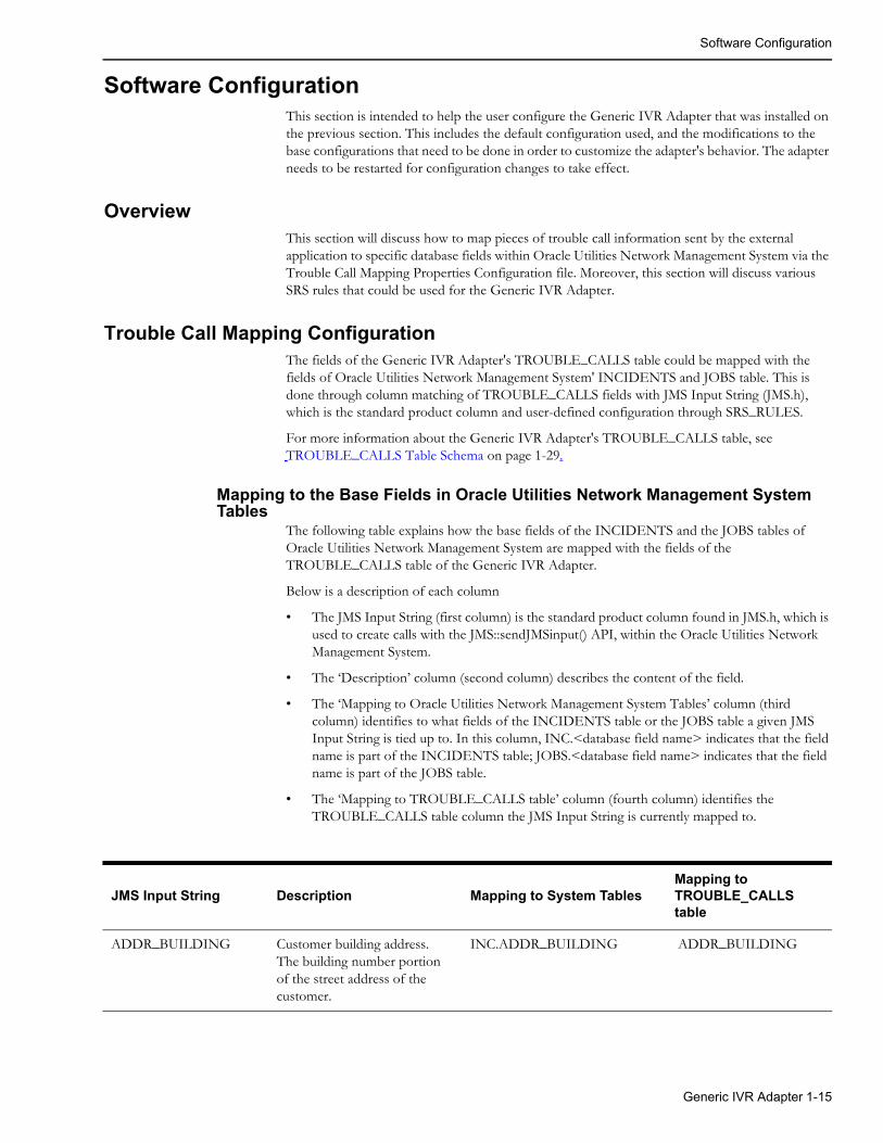
Software Configuration
Software ConfigurationThis section is intended to help the user configure the Generic IVR Adapter that was installed on the previous section. This includes the default configuration used, and the modifications to the base configurations that need to be done in order to customize the adapter's behavior. The adapter needs to be restarted for configuration changes to take effect.
OverviewThis section will discuss how to map pieces of trouble call information sent by the external application to specific database fields within Oracle Utilities Network Management System via the Trouble Call Mapping Properties Configuration file. Moreover, this section will discuss various SRS rules that could be used for the Generic IVR Adapter.
Trouble Call Mapping ConfigurationThe fields of the Generic IVR Adapter's TROUBLE_CALLS table could be mapped with the fields of Oracle Utilities Network Management System' INCIDENTS and JOBS table. This is done through column matching of TROUBLE_CALLS fields with JMS Input String (JMS.h), which is the standard product column and user-defined configuration through SRS_RULES.
For more information about the Generic IVR Adapter's TROUBLE_CALLS table, see TROUBLE_CALLS Table Schema on page 1-29.
Mapping to the Base Fields in Oracle Utilities Network Management System Tables
The following table explains how the base fields of the INCIDENTS and the JOBS tables of Oracle Utilities Network Management System are mapped with the fields of the TROUBLE_CALLS table of the Generic IVR Adapter.
Below is a description of each column
• The JMS Input String (first column) is the standard product column found in JMS.h, which is used to create calls with the JMS::sendJMSinput() API, within the Oracle Utilities Network Management System.
• The ‘Description’ column (second column) describes the content of the field.
• The ‘Mapping to Oracle Utilities Network Management System Tables’ column (third column) identifies to what fields of the INCIDENTS table or the JOBS table a given JMS Input String is tied up to. In this column, INC.<database field name> indicates that the field name is part of the INCIDENTS table; JOBS.<database field name> indicates that the field name is part of the JOBS table.
• The ‘Mapping to TROUBLE_CALLS table’ column (fourth column) identifies the TROUBLE_CALLS table column the JMS Input String is currently mapped to.
JMS Input String Description Mapping to System TablesMapping to TROUBLE_CALLS table
ADDR_BUILDING Customer building address. The building number portion of the street address of the customer.
INC.ADDR_BUILDING ADDR_BUILDING
Generic IVR Adapter 1-15

Software Configuration
ADDR_CITY Customer city. The city or city/state portion of the address of the customer.
INC.ADDR_CITY ADDR_CITY
ADDR_CROSS_STREET
Intersection cross street name. Name of the second cross street should be in ADDR_STREET field.
INC.ADDR_CROSS_STREET ADDR_CROSS_STREET
ADDR_STREET Customer street address. The full street address of the customer.
INC.ADDRESSJOBS.ADDR_STREET
ADDR_STREET
ALTERNATE_PHONE Alternative contact number. Alternate phone number for contacting the customer.
INC.ALTERNATE_PHONE ALTERNATE_PHONE
APPT_RANGE Appointment Range. INC.APPT_RANGE APPT_RANGE
APPT_TIME Time of appointment. INC.APPT_TIME APPT_TIME
APPT_TYPE Type of appointment. INC.APPT_TYPE APPT_TYPE
CALL_TIME Input time of call. The input time of the incident. If not provided, the current time will be used.
INC.INPUT_TIME CALL_TIME
CALL_TYPE Type of call. INC.TYPE CALL_TYPE
CALLBACK_LATE Callback late indicator. Indicates that it is OK to call back the customer beyond a defined ‘late’ time. This information is only stored in Oracle Utilities Network Management System. No other action is taken by Oracle Utilities Network Management System.
INC.CALLBACK_LATE CALLBACK_LATE
CALLBACK_REQUEST Indicates either a callback is requested or not.
INC.CALLBACK_REQUEST CALLBACK_REQUEST
CALLBACK_TIME Time callback requested. Time for which callback or a follow-up call was requested.
INC.CALLBACK_TIME CALLBACK_TIME
JMS Input String Description Mapping to System TablesMapping to TROUBLE_CALLS table
1-16 Oracle Utilities Network Management System Adapters Guide
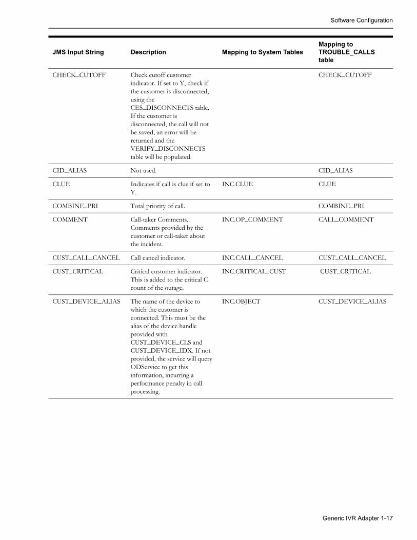
Software Configuration
CHECK_CUTOFF Check cutoff customer indicator. If set to Y, check if the customer is disconnected, using the CES_DISCONNECTS table. If the customer is disconnected, the call will not be saved, an error will be returned and the VERIFY_DISCONNECTS table will be populated.
CHECK_CUTOFF
CID_ALIAS Not used. CID_ALIAS
CLUE Indicates if call is clue if set to Y.
INC.CLUE CLUE
COMBINE_PRI Total priority of call. COMBINE_PRI
COMMENT Call-taker Comments. Comments provided by the customer or call-taker about the incident.
INC.OP_COMMENT CALL_COMMENT
CUST_CALL_CANCEL Call cancel indicator. INC.CALL_CANCEL CUST_CALL_CANCEL
CUST_CRITICAL Critical customer indicator. This is added to the critical C count of the outage.
INC.CRITICAL_CUST CUST_CRITICAL
CUST_DEVICE_ALIAS The name of the device to which the customer is connected. This must be the alias of the device handle provided with CUST_DEVICE_CLS and CUST_DEVICE_IDX. If not provided, the service will query ODService to get this information, incurring a performance penalty in call processing.
INC.OBJECT CUST_DEVICE_ALIAS
JMS Input String Description Mapping to System TablesMapping to TROUBLE_CALLS table
Generic IVR Adapter 1-17
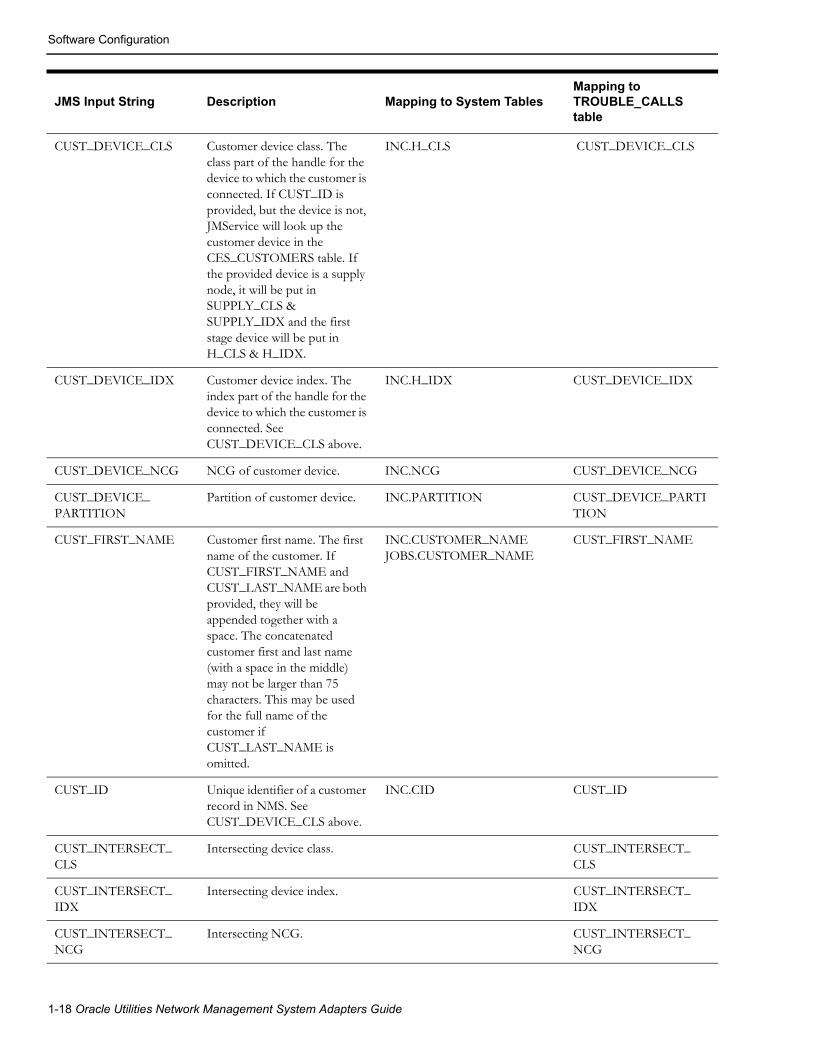
Software Configuration
CUST_DEVICE_CLS Customer device class. The class part of the handle for the device to which the customer is connected. If CUST_ID is provided, but the device is not, JMService will look up the customer device in the CES_CUSTOMERS table. If the provided device is a supply node, it will be put in SUPPLY_CLS & SUPPLY_IDX and the first stage device will be put in H_CLS & H_IDX.
INC.H_CLS CUST_DEVICE_CLS
CUST_DEVICE_IDX Customer device index. The index part of the handle for the device to which the customer is connected. See CUST_DEVICE_CLS above.
INC.H_IDX CUST_DEVICE_IDX
CUST_DEVICE_NCG NCG of customer device. INC.NCG CUST_DEVICE_NCG
CUST_DEVICE_PARTITION
Partition of customer device. INC.PARTITION CUST_DEVICE_PARTITION
CUST_FIRST_NAME Customer first name. The first name of the customer. If CUST_FIRST_NAME and CUST_LAST_NAME are both provided, they will be appended together with a space. The concatenated customer first and last name (with a space in the middle) may not be larger than 75 characters. This may be used for the full name of the customer if CUST_LAST_NAME is omitted.
INC.CUSTOMER_NAMEJOBS.CUSTOMER_NAME
CUST_FIRST_NAME
CUST_ID Unique identifier of a customer record in NMS. See CUST_DEVICE_CLS above.
INC.CID CUST_ID
CUST_INTERSECT_CLS
Intersecting device class. CUST_INTERSECT_CLS
CUST_INTERSECT_IDX
Intersecting device index. CUST_INTERSECT_IDX
CUST_INTERSECT_NCG
Intersecting NCG. CUST_INTERSECT_NCG
JMS Input String Description Mapping to System TablesMapping to TROUBLE_CALLS table
1-18 Oracle Utilities Network Management System Adapters Guide

Software Configuration
CUST_INTR_X Intersecting X coordinate. X coordinate used for intersection grouping. See streetXsectionOffset SRS Rule for more information.
CUST_INTR_X
CUST_INTR_Y Intersecting Y coordinate. Y coordinate used for intersection grouping. See streetXsectionOffset SRS Rule for more information.
CUST_INTR_Y
CUST_KEY Customer account number. INC.ACCOUNT_NUM CUST_KEY
CUST_LAST_NAME The last name of the customer. See CUST_FIRST_NAME above.
INC.CUSTOMER_NAMEJOBS.CUSTOMER_NAME
CUST_LAST_NAME
CUST_LIFE_SUPPORT Life support customer. If set to ‘Y’, indicates a life support customer. This is added to the critical K count of the outage.
INC.LIFE_SUPPORT CUST_LIFE_SUPPORT
CUST_ORDER_NUM Customer order number. Not used in the Oracle Utilities Network Management System.
INC.ORDER_NUMBER CUST_ORDER_NUM
CUST_PHONE Customer phone number. The non-area code portion of the customer phone number. If both CUST_PHONE and CUST_PHONE_AREA are provided, they will be appended according to the customerPhoneParentheses SRS rule. The concatenated customer phone number and area (including parentheses) may not be larger than 32 characters. This field may be used for the full customer phone number if CUST_PHONE_AREA is omitted. See customerPhoneParentheses SRS Rule for more information.
INC.CUSTOMER_PHONEJOBS.CUSTOMER_PHONE
CUST_PHONE
CUST_PHONE_AREA Customer phone area code. The area code portion of the customer phone number. See CUST_PHONE above.
INC.CUSTOMER_PHONEJOBS.CUSTOMER_PHONE
CUST_PHOHE_AREA
JMS Input String Description Mapping to System TablesMapping to TROUBLE_CALLS table
Generic IVR Adapter 1-19
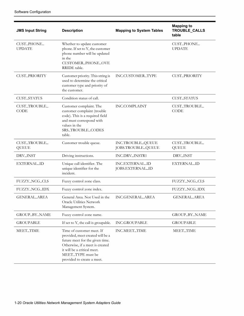
Software Configuration
CUST_PHONE_UPDATE
Whether to update customer phone. If set to Y, the customer phone number will be updated in the CUSTOMER_PHONE_OVERRIDE table.
CUST_PHONE_UPDATE
CUST_PRIORITY Customer priority. This string is used to determine the critical customer type and priority of the customer.
INC.CUSTOMER_TYPE CUST_PRIORITY
CUST_STATUS Condition status of call. CUST_STATUS
CUST_TROUBLE_CODE
Customer complaint. The customer complaint (trouble code). This is a required field and must correspond with values in the SRS_TROUBLE_CODES table.
INC.COMPLAINT CUST_TROUBLE_CODE
CUST_TROUBLE_QUEUE
Customer trouble queue. INC.TROUBLE_QUEUEJOBS.TROUBLE_QUEUE
CUST_TROUBLE_QUEUE
DRV_INST Driving instructions. INC.DRV_INSTR1 DRV_INST
EXTERNAL_ID Unique call identifier. The unique identifier for the incident.
INC.EXTERNAL_IDJOBS.EXTERNAL_ID
EXTERNAL_ID
FUZZY_NCG_CLS Fuzzy control zone class. FUZZY_NCG_CLS
FUZZY_NCG_IDX Fuzzy control zone index. FUZZY_NCG_IDX
GENERAL_AREA General Area. Not Used in the Oracle Utilities Network Management System.
INC.GENERAL_AREA GENERAL_AREA
GROUP_BY_NAME Fuzzy control zone name. GROUP_BY_NAME
GROUPABLE If set to Y, the call is groupable. INC.GROUPABLE GROUPABLE
MEET_TIME Time of customer meet. If provided, meet created will be a future meet for the given time. Otherwise, if a meet is created it will be a critical meet. MEET_TYPE must be provided to create a meet.
INC.MEET_TIME MEET_TIME
JMS Input String Description Mapping to System TablesMapping to TROUBLE_CALLS table
1-20 Oracle Utilities Network Management System Adapters Guide

Software Configuration
During initialization of IVRAdapter, TROUBLE_CALLS column are matched with the standard product column (JMS.h). If TROUBLE_CALLS field does not match, error will be logged and IVRAdapter will exit.
The following are some exceptions when matching TROUBLE_CALLS columns with JMS Input String:
MEET_TYPE Customer meet type. If set to 1, a new meet will be created. If set to 2, an existing meet will be rescheduled. If set to 3, an existing meet will be canceled. If any other value is provided, no meet will be created. May be used in conjunction with MEET_TIME.
INC.MEET_CODE MEET_TYPE
METER_ID Customer meter number. INC.METER_ID METER_ID
POWER_UP Power-up call. Used for power-up messages from CellNet. Used for AMR.
POWER_UP
RELATED_EVT_APP Related event application. RELATED_EVT_APP
RELATED_EVT_CLS Related event class. INC. RELATED_CLS RELATED_EVT_CLS
RELATED_EVT_IDX Related event index. INC. RELATED_IDX RELATED_EVT_IDX
REPORTED_ERT Est rest time reported to caller. INC. REPORTED_EST_REST_TIME
REPORTED_ERT
SHORT_DESC Short description of trouble. INC.SHORT_DESC SHORT_DESC
TROUBLE_LOC Incident's trouble location. INC.TROUBLE_LOC TROUBLE_LOC
UPDATE_EXISTING_INC
Whether to update an existing incident. If set to 1, then JMService will replace an existing incident for the same customer with the values passed in this call.
UPDATE_EXISTING_INC
USER_NAME Call-taker user name. The name of the call-taker or interface that created the call.
INC.USER_NAME USER_NAME
X_REF Customer X coordinate. X coordinate of customer or customer device.
INC.X_COORD X_REF
Y_REF Customer Y coordinate. Y coordinate of customer or customer device.
INC.Y_COORD Y_REF
JMS Input String Description Mapping to System TablesMapping to TROUBLE_CALLS table
Generic IVR Adapter 1-21
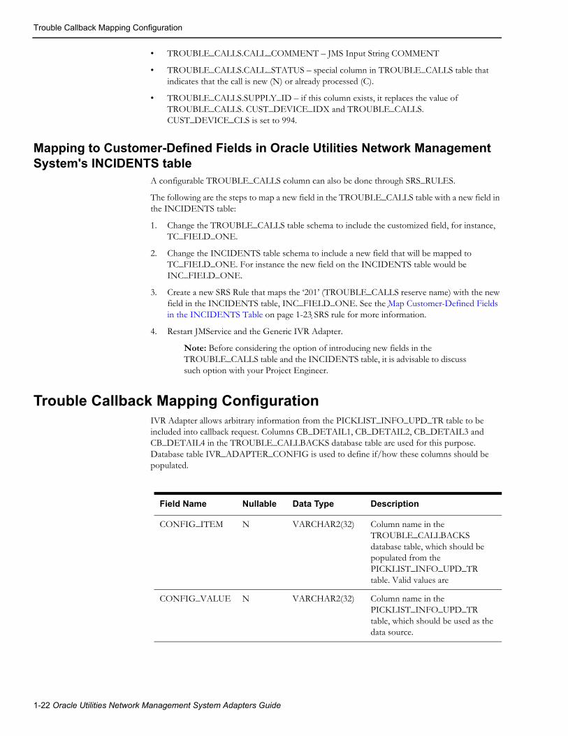
Trouble Callback Mapping Configuration
• TROUBLE_CALLS.CALL_COMMENT – JMS Input String COMMENT
• TROUBLE_CALLS.CALL_STATUS – special column in TROUBLE_CALLS table that indicates that the call is new (N) or already processed (C).
• TROUBLE_CALLS.SUPPLY_ID – if this column exists, it replaces the value of TROUBLE_CALLS. CUST_DEVICE_IDX and TROUBLE_CALLS. CUST_DEVICE_CLS is set to 994.
Mapping to Customer-Defined Fields in Oracle Utilities Network Management System's INCIDENTS table
A configurable TROUBLE_CALLS column can also be done through SRS_RULES.
The following are the steps to map a new field in the TROUBLE_CALLS table with a new field in the INCIDENTS table:
1. Change the TROUBLE_CALLS table schema to include the customized field, for instance, TC_FIELD_ONE.
2. Change the INCIDENTS table schema to include a new field that will be mapped to TC_FIELD_ONE. For instance the new field on the INCIDENTS table would be INC_FIELD_ONE.
3. Create a new SRS Rule that maps the ‘201’ (TROUBLE_CALLS reserve name) with the new field in the INCIDENTS table, INC_FIELD_ONE. See the Map Customer-Defined Fields in the INCIDENTS Table on page 1-23 SRS rule for more information.
4. Restart JMService and the Generic IVR Adapter.
Note: Before considering the option of introducing new fields in the TROUBLE_CALLS table and the INCIDENTS table, it is advisable to discuss such option with your Project Engineer.
Trouble Callback Mapping ConfigurationIVR Adapter allows arbitrary information from the PICKLIST_INFO_UPD_TR table to be included into callback request. Columns CB_DETAIL1, CB_DETAIL2, CB_DETAIL3 and CB_DETAIL4 in the TROUBLE_CALLBACKS database table are used for this purpose. Database table IVR_ADAPTER_CONFIG is used to define if/how these columns should be populated.
Field Name Nullable Data Type Description
CONFIG_ITEM N VARCHAR2(32) Column name in the TROUBLE_CALLBACKS database table, which should be populated from the PICKLIST_INFO_UPD_TR table. Valid values are
CONFIG_VALUE N VARCHAR2(32) Column name in the PICKLIST_INFO_UPD_TR table, which should be used as the data source.
1-22 Oracle Utilities Network Management System Adapters Guide

SRS Rules Configuration
SRS Rules ConfigurationThe following are SRS rules that could be used with the Generic IVR Adapter. These SRS rules can be included in the <project>_srs_rules.sql file.
Map Customer-Defined Fields in the INCIDENTS TableOracle Utilities Network Management System and the Generic IVR Adapter provides a mechanism to receive additional trouble call information from the external application and have this information stored in a new customer-defined field in the INCIDENTS table of Oracle Utilities Network Management System.
The configurable TROUBLE_CALLS column name has special names ‘201’, ‘202’, up to ‘209’ to serve this purpose. Normally, a regular column name in TROUBLE_CALLS like CALL_COMMENT or COMMENT in JMS Input String is tied to a specific field of the INCIDENTS table by default. For this case, it's the OP_COMMENT field. A special name like ‘201’ could be mapped to a new field in the INCIDENTS table by using an SRS rule. The table below details how an SRS rule could be used to do this mapping. An SRS rule like this has to be used for each mapping. See Map Customer-Defined Fields in the INCIDENTS Table on page 1-23 for more information.
Field Name Value
SET_NAME ‘config_incident’
INCIDENT_TYPE ‘customer_defined’
RULE_NAME the name of the new column in the INCIDENTS table
RULE_VALUE_1 ‘str’, ‘date’, ‘int’, ‘float’‘str’ is for strings, ‘date’ is for dates, ‘int’ is for integers, and ‘float’ is for floats. This represents the data type of the new column.
RULE_VALUE_2 An integer, representing the value of the SRS input configuration item specifying this field -- must have a value of 200 or greater
RULE_VALUE_INTEGER_1 0 (not used)
RULE_VALUE_INTEGER_2 0 (not used)
RULE_VALUE_INTEGER_3 0 (not used)
RULE_VALUE_INTEGER_4 0 (not used)
RULE_VALUE_INTEGER_5 0 (not used)
Generic IVR Adapter 1-23

SRS Rules Configuration
callbackInterfaceEnabled SRS RuleIf set to ‘yes’ then SRS APIs for manipulating callback information will become available. It has to be set to ‘yes’ for Web Callback GUI to operate. This rule holds outage information in JMService memory on a special data structure until this time expires OR all customer callbacks for the outage are complete.
Field Name Value
SET_NAME ‘config’
INCIDENT_TYPE ‘any’
RULE_VALUE_1 ‘yes’ or ‘no’ (default: ‘no’)
RULE_VALUE_2 0 (not used)
RULE_VALUE_INTEGER_1 0 (not used)
RULE_VALUE_INTEGER_2 0 (not used)
RULE_VALUE_INTEGER_3 0 (not used)
RULE_VALUE_INTEGER_4 0 (not used)
RULE_VALUE_INTEGER_5 0 (not used)
1-24 Oracle Utilities Network Management System Adapters Guide

SRS Rules Configuration
useExternalCause SRS RuleIf set to ‘yes’ then the IVR Adapter’s callback requests data flow will include the cause code when it populates the TROUBLE_CALLBACKS table. The cause code value will be taken from JOBS.CAUSE.
customerPhoneParentheses SRS RuleIf rule_value_1 set to ‘yes’, parentheses will be added to customer call phone numbers in the following format: (AREA)NUMBER. Otherwise, the number and area will be concatenated together without parentheses.
Field Name Value
SET_NAME ‘config’
INCIDENT_TYPE ‘any’
RULE_VALUE_1 ‘yes’ or ‘no’ (default: ‘yes’)
RULE_VALUE_2 0 (not used)
RULE_VALUE_INTEGER_1 0 (not used)
RULE_VALUE_INTEGER_2 0 (not used)
RULE_VALUE_INTEGER_3 0 (not used)
RULE_VALUE_INTEGER_4 0 (not used)
RULE_VALUE_INTEGER_5 0 (not used)
Field Name Value
SET_NAME ‘config’
INCIDENT_TYPE ‘any’
RULE_VALUE_1 ‘yes’ or ‘no’ (Default: ‘yes’)
RULE_VALUE_2 0 (not used)
RULE_VALUE_INTEGER_1 0 (not used)
RULE_VALUE_INTEGER_2 0 (not used)
RULE_VALUE_INTEGER_3 0 (not used)
RULE_VALUE_INTEGER_4 0 (not used)
RULE_VALUE_INTEGER_5 0 (not used)
Generic IVR Adapter 1-25
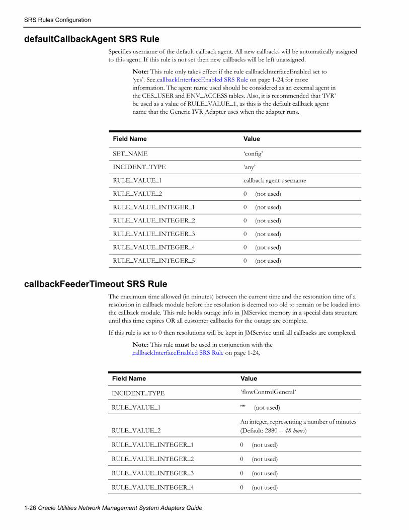
SRS Rules Configuration
defaultCallbackAgent SRS RuleSpecifies username of the default callback agent. All new callbacks will be automatically assigned to this agent. If this rule is not set then new callbacks will be left unassigned.
Note: This rule only takes effect if the rule callbackInterfaceEnabled set to ‘yes’. See callbackInterfaceEnabled SRS Rule on page 1-24 for more information. The agent name used should be considered as an external agent in the CES_USER and ENV_ACCESS tables. Also, it is recommended that ‘IVR’ be used as a value of RULE_VALUE_1, as this is the default callback agent name that the Generic IVR Adapter uses when the adapter runs.
callbackFeederTimeout SRS RuleThe maximum time allowed (in minutes) between the current time and the restoration time of a resolution in callback module before the resolution is deemed too old to remain or be loaded into the callback module. This rule holds outage info in JMService memory in a special data structure until this time expires OR all customer callbacks for the outage are complete.
If this rule is set to 0 then resolutions will be kept in JMService until all callbacks are completed.
Note: This rule must be used in conjunction with the callbackInterfaceEnabled SRS Rule on page 1-24.
Field Name Value
SET_NAME ‘config’
INCIDENT_TYPE ‘any’
RULE_VALUE_1 callback agent username
RULE_VALUE_2 0 (not used)
RULE_VALUE_INTEGER_1 0 (not used)
RULE_VALUE_INTEGER_2 0 (not used)
RULE_VALUE_INTEGER_3 0 (not used)
RULE_VALUE_INTEGER_4 0 (not used)
RULE_VALUE_INTEGER_5 0 (not used)
Field Name Value
INCIDENT_TYPE ‘flowControlGeneral’
RULE_VALUE_1 "" (not used)
RULE_VALUE_2An integer, representing a number of minutes (Default: 2880 -- 48 hours)
RULE_VALUE_INTEGER_1 0 (not used)
RULE_VALUE_INTEGER_2 0 (not used)
RULE_VALUE_INTEGER_3 0 (not used)
RULE_VALUE_INTEGER_4 0 (not used)
1-26 Oracle Utilities Network Management System Adapters Guide

SRS Rules Configuration
streetXsectionOffset SRS RuleSpecifies the size of the maximum bounding rectangle to be used in grouping street intersection fuzzy calls to supply nodes. The rectangle will be the area where:
x E [xsection_x - THIS RULE VALUE, xsection_x + THIS RULE VALUE] and y E [xsection_y - THIS RULE VALUE, xsection_y + THIS RULE VALUE]
This is an integer. Check your world coordinate system for a reasonable integer value.
This rule is used once for each rectangle desired (i.e., multiple instances of this rule may exist in a single rule set). For example, a larger rectangle size may be desired in a rural control zone and a smaller rectangle in an urban control zone.
RULE_VALUE_INTEGER_5 0 (not used)
Field Name Value
Field Name Value
RULE_VALUE_1 ‘‘ (not used)
RULE_VALUE_2 integer (Default: none)
RULE_VALUE_INTEGER_1 0 (not used)
RULE_VALUE_INTEGER_2 0 (not used)
RULE_VALUE_INTEGER_3 0 (not used)
RULE_VALUE_INTEGER_4 0 (not used)
RULE_VALUE_INTEGER_5 0 (not used)
NCG_CLSinteger, representing ncg_cls of desired applicable control zone level
NCG_IDXinteger, representing ncg_idx of desired applicable control zone level
Generic IVR Adapter 1-27
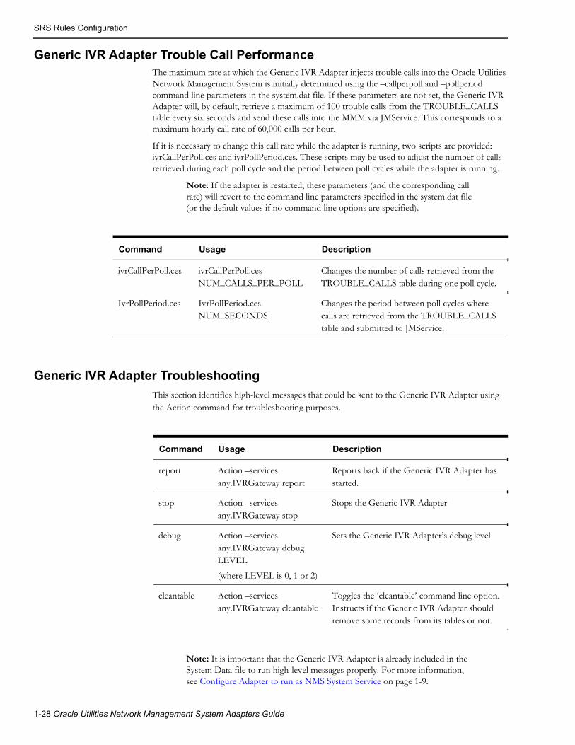
SRS Rules Configuration
Generic IVR Adapter Trouble Call PerformanceThe maximum rate at which the Generic IVR Adapter injects trouble calls into the Oracle Utilities Network Management System is initially determined using the –callperpoll and –pollperiod command line parameters in the system.dat file. If these parameters are not set, the Generic IVR Adapter will, by default, retrieve a maximum of 100 trouble calls from the TROUBLE_CALLS table every six seconds and send these calls into the MMM via JMService. This corresponds to a maximum hourly call rate of 60,000 calls per hour.
If it is necessary to change this call rate while the adapter is running, two scripts are provided: ivrCallPerPoll.ces and ivrPollPeriod.ces. These scripts may be used to adjust the number of calls retrieved during each poll cycle and the period between poll cycles while the adapter is running.
Note: If the adapter is restarted, these parameters (and the corresponding call rate) will revert to the command line parameters specified in the system.dat file (or the default values if no command line options are specified).
Generic IVR Adapter Troubleshooting
This section identifies high-level messages that could be sent to the Generic IVR Adapter using the Action command for troubleshooting purposes.
Note: It is important that the Generic IVR Adapter is already included in the System Data file to run high-level messages properly. For more information, see Configure Adapter to run as NMS System Service on page 1-9.
Command Usage Description
ivrCallPerPoll.ces ivrCallPerPoll.ces NUM_CALLS_PER_POLL
Changes the number of calls retrieved from the TROUBLE_CALLS table during one poll cycle.
IvrPollPeriod.ces IvrPollPeriod.ces NUM_SECONDS
Changes the period between poll cycles where calls are retrieved from the TROUBLE_CALLS table and submitted to JMService.
Command Usage Description
report Action –services any.IVRGateway report
Reports back if the Generic IVR Adapter has started.
stop Action –services any.IVRGateway stop
Stops the Generic IVR Adapter
debug Action –services any.IVRGateway debug LEVEL
(where LEVEL is 0, 1 or 2)
Sets the Generic IVR Adapter’s debug level
cleantable Action –services any.IVRGateway cleantable
Toggles the ‘cleantable’ command line option. Instructs if the Generic IVR Adapter should remove some records from its tables or not.
1-28 Oracle Utilities Network Management System Adapters Guide

Database Schema
Database Schema
OverviewThe following section defines in detail the schema of each database tables used by the Generic IVR Adapter. This section defines the parameters used by the Generic IVR Adapter’s stored procedures.
Database Table Schema
TROUBLE_CALLS Table SchemaThe TROUBLE_CALLS table stores the trouble calls that are submitted by the external application. The Generic IVR Adapter polls this table and submits new trouble call records to Oracle Utilities Network Management System, so Oracle Utilities Network Management System could apply the outage analysis algorithm to predict the outage device. The external application indirectly inserts records to the TROUBLE_CALLS table by invoking the pr_trouble_calls stored procedure. See pr_trouble_calls on page 1-53 for more information.
Each field of the TROUBLE_CALLS table is matched with SRSinput field. The mapping is configurable. A column names are directly tied up to a specific field of the INCIDENTS table or the JOBS table of Oracle Utilities Network Management System.
In effect, each field in the TROUBLE_CALLS table is mapped (and the mapping is configurable) to a particular field of the INCIDENTS table or the JOBS table of Oracle Utilities Network Management System. For more information, see Trouble Call Mapping Configuration on page 1-15.
In the 'Description' column, take note that field names prefixed with 'INC.' would come from the INCIDENTS table. Field names prefixed by 'JOBS.' would come from the JOBS table. Field names prefixed by 'CC.' would come from the CES_CUSTOMERS table.
Field Name Nullable Data Type Description (JMS Input String Reference)
ADDR_BUILDING Y VARCHAR2(10) Customer building address. Refer to ADDR_BUILDING for more information.
Map to INC.ADDR_BUILDING
ADDR_CITY Y VARCHAR2(45) Customer City/State. Refer to ADDR_CITY for more information.
Maps to INC.ADDR_CITY
ADDR_CROSS_STREET Y VARCHAR2(255) Intersection cross street name.
Maps to INC.ADDR_CROSS_STREET.
ADDR_STREET Y VARCHAR2(255) Customer address. Refer to ADDR_STREET for more information.
Maps to INC.ADDRESS and JOBS.ADDR_STREET
ALTERNATE_PHONE Y VARCHAR2(32) Alternative contact number. Refer to ALTERNATE_PHONE for more information.
Maps to INC.ALTERNATE_PHONE
Generic IVR Adapter 1-29

Database Schema
APPT_RANGE Y NUMBER Appointment Range. Refer to APPT_RANGE for more information.
Maps to INC.APPT_RANGE.
APPT_TIME Y DATE Time of appointment. Refer to APPT_TIME for more information.
Maps to INC.APPT_TIME.
APPT_TYPE Y VARCHAR2(16) Type of appointment. Refer to APPT_TYPE for more information.
Maps to INC.APPT_TYPE.
CALL_COMMENT Y VARCHAR2(255) Customer Comment. Refer to COMMENT Property Name for more information.
Maps to INC.OP_COMMENT.
CALL_ID Y VARCHAR2(16) Not used.
CALL_STATUS Y VARCHAR2(1) Status of the trouble call in the TROUBLE_CALLS table. The Generic IVR Adapter uses this internally to identify the status of this trouble call.
The possible values are as follows:
‘N’ - New trouble call
‘I’ - The Generic IVR Adapter is in the process of submitting this trouble call to Oracle Utilities Network Management System
‘C’ - Trouble call submission to Oracle Utilities Network Management System is completed.
The Generic IVR Adapter uses this field as one of the criteria in purging the TROUBLE_CALLS table for 'old' records. Records with CALL_STATUS field = 'C' will be purged.
CALL_TIME N DATE Input time of call. Refer to CALL_TIME for more information.
Maps to INC.INPUT_TIME
The Generic IVR Adapter uses this field as one of the criteria in purging the TROUBLE_CALLS table for 'old' records. The TROUBLE_CALL record is 'aged' based on the system date/time and the CALL_TIME field. Any record older than a predefined number of days will be removed. See keepdbinfo for more information.
CALL_TYPE Y VARCHAR2(8) Type of call. Refer to CALL_TYPE for more information.
Maps to INC.TYPE
Field Name Nullable Data Type Description (JMS Input String Reference)
1-30 Oracle Utilities Network Management System Adapters Guide

Database Schema
CALLBACK_LATE Y VARCHAR2(1) Callback late indicator. Refer to CALLBACK_LATE for more information.
The possible values are as follows:
‘Y’ - It is OK to call back even when it is already late.
‘N’ - It is not OK to call back when it is already late.
If no value was supplied, this field will default to 'N'.
This information is only passed from the external application to Oracle Utilities Network Management System (using the Trouble Calls Data Flow), and back to the external application (using the Callback Requests Data Flow). No other action is taken.
CALLBACK_REQUEST Y NUMBER Callback request indicator. Refer to CALLBACK_REQUEST for more information.
The possible values are as follows:
‘0’ - callback not requested
‘1’ - callback requested
Maps to INC.CALLBACK_REQUEST
CALLBACK_TIME Y DATE Callback Before Time. Refer to CALLBACK_TIME for more information.
Maps to INC.CALLBACK_TIME
CHECK_CUTOFF Y VARCHAR2(1) Check cut-off customer indicator. Refer to CHECK_CUTOFF for more information.
The possible values are as follows:
‘Y’ - check if the customer is disconnected
‘N’ - do not perform checking.
CLUE Y NUMBER Indicates if call is clue if set to Y. Refer to CLUE on page 1-17 for more information.
Maps to INC.CLUE
COMBINE_PRI Y NUMBER Total priority of call. Refer to COMBINE_PRI for more information.
CUST_CALL_CANCEL Y VARCHAR2(1) Call cancel indicator. Refer to CUST_CALL_CANCEL for more information.
Maps to INC.CALL_CANCEL
CUST_CRITICAL Y VARCHAR2(1) Critical customer indicator. This is added to the critical C count of the outage. Refer to CUST_CRITICAL for more information.
Maps to INC.CRITICAL_CUST
Field Name Nullable Data Type Description (JMS Input String Reference)
Generic IVR Adapter 1-31

Database Schema
CUST_DEVICE_ALIAS Y VARCHAR2(32) Customer Device Alias. Refer to CUST_DEVICE_ALIAS for more information.
Maps to INC.OBJECT
CUST_DEVICE_CLS Y NUMBER Corresponding CC.H_CLS field for the given CC.SERV_LOC_ID. This field does not have a corresponding input parameter in the pr_trouble_calls stored procedure. The stored procedure itself populates this field. Refer to CUST_DEVICE_CLS for more information.
Maps to INC.H_CLS
CUST_DEVICE_IDX Y NUMBER Corresponding CC.H_IDX field for the given CC.SERV_LOC_ID. This field does not have a corresponding input parameter in the pr_trouble_calls stored procedure. The stored procedure itself populates this field. Refer to CUST_DEVICE_IDX for more information.
Maps to INC.H_IDX
CUST_DEVICE_NCG Y NUMBER NCG of customer device. Refer to CUST_DEVICE_NCG for more information.
Maps to INC.NCG
CUST_DEVICE_PARTITION Y NUMBER Partition of customer device. Refer to CUST_DEVICE_ PARTITION for more information.
Maps to INC.PARTITION
CUST_FIRST_NAME Y VARCHAR2(75) Customer Name. Refer to CUST_FIRST_NAME for more information.
Maps to INC.CUSTOMER_NAME and
JOBS.CUSTOMER_NAME
CUST_ID Y VARCHAR2(64) Unique customer record identifier. Maps to INC.CID.
CUST_INTERSECT_CLS Y NUMBER Intersecting device class. Refer to CUST_INTERSECT_ CLS for more information.
CUST_INTERSECT_IDX Y NUMBER Intersecting device index. Refer to CUST_INTERSECT_ IDX for more information.
CUST_INTERSECT_NCG Y NUMBER Intersecting NCG. Refer to CUST_INTERSECT_ NCG for more information.
CUST_INTR_X Y NUMBER Intersecting X coordinate. X coordinate used for intersection grouping.
Field Name Nullable Data Type Description (JMS Input String Reference)
1-32 Oracle Utilities Network Management System Adapters Guide
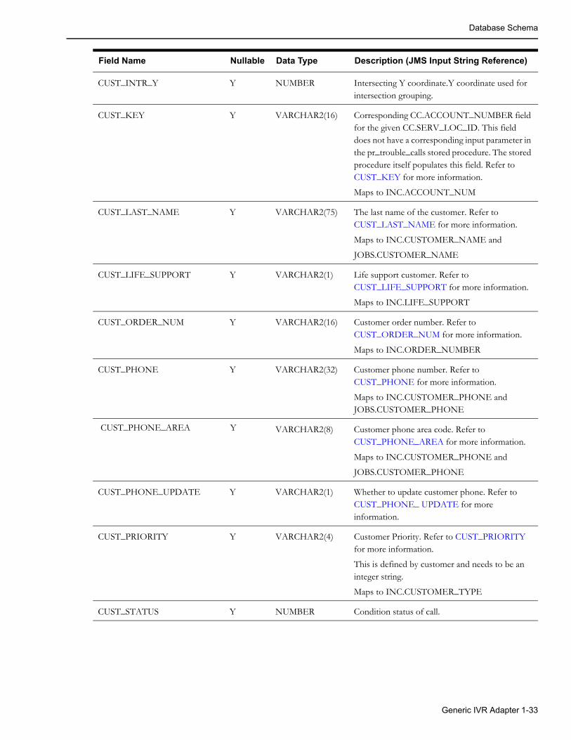
Database Schema
CUST_INTR_Y Y NUMBER Intersecting Y coordinate.Y coordinate used for intersection grouping.
CUST_KEY Y VARCHAR2(16) Corresponding CC.ACCOUNT_NUMBER field for the given CC.SERV_LOC_ID. This field does not have a corresponding input parameter in the pr_trouble_calls stored procedure. The stored procedure itself populates this field. Refer to CUST_KEY for more information.
Maps to INC.ACCOUNT_NUM
CUST_LAST_NAME Y VARCHAR2(75) The last name of the customer. Refer to CUST_LAST_NAME for more information.
Maps to INC.CUSTOMER_NAME and
JOBS.CUSTOMER_NAME
CUST_LIFE_SUPPORT Y VARCHAR2(1) Life support customer. Refer to CUST_LIFE_SUPPORT for more information.
Maps to INC.LIFE_SUPPORT
CUST_ORDER_NUM Y VARCHAR2(16) Customer order number. Refer to CUST_ORDER_NUM for more information.
Maps to INC.ORDER_NUMBER
CUST_PHONE Y VARCHAR2(32) Customer phone number. Refer to CUST_PHONE for more information.
Maps to INC.CUSTOMER_PHONE and JOBS.CUSTOMER_PHONE
CUST_PHONE_AREA Y VARCHAR2(8) Customer phone area code. Refer to CUST_PHONE_AREA for more information.
Maps to INC.CUSTOMER_PHONE and
JOBS.CUSTOMER_PHONE
CUST_PHONE_UPDATE Y VARCHAR2(1) Whether to update customer phone. Refer to CUST_PHONE_ UPDATE for more information.
CUST_PRIORITY Y VARCHAR2(4) Customer Priority. Refer to CUST_PRIORITY for more information.
This is defined by customer and needs to be an integer string.
Maps to INC.CUSTOMER_TYPE
CUST_STATUS Y NUMBER Condition status of call.
Field Name Nullable Data Type Description (JMS Input String Reference)
Generic IVR Adapter 1-33

Database Schema
CUST_TROUBLE_CODE N VARCHAR2(10) Trouble code or customer complaint. Refer to CUST_TROUBLE_ CODE for more information.
This is the trouble or complaint that the customer reports when making a call. The trouble code determines the priority of the incident.
Trouble code mapping setup in Oracle Utilities Network Management System should be synchronized with the trouble code mapping setup on the external application. This is to ensure that the trouble code sent from the external application is interpreted similarly when the trouble code is received by Oracle Utilities Network Management System.
Maps to INC.COMPLAINT
CUST_TROUBLE_QUEUE Y VARCHAR2(10) Customer trouble queue. Refer to CUST_TROUBLE_ QUEUE for more information.
This field contains the name of the work group queue that the event has been referred to.
Maps to INC.TROUBLE_QUEUE and JOBS.TROUBLE_QUEUE
DRV_INST Y VARCHAR2(180) Driving instructions.
Maps to INC.DRV_INSTR1
EXTERNAL_ID N VARCHAR2(16) External ID. Refer to EXTERNAL_ID for more information
If it is used, its value should be unique.
Maps to INC.EXTERNAL_ID and
JOBS.EXTERNAL_ID
FUZZY_NCG_CLS Y NUMBER Fuzzy control zone class.
FUZZY_NCG_IDX Y NUMBER Fuzzy control zone index.
GENERAL_AREA Y VARCHAR2(32) General Area. Not Used in the SPL OMS System.
Maps to INC.GENERAL_AREA
GROUP_BY_NAME Y VARCHAR2(127) Fuzzy control zone name.
GROUPABLE Y NUMBER Indicates if call is groupable if set to 1.
Maps to INC.GROUPABLE
MEET_TIME Y DATE Time of customer meet. Refer to MEET_TIME for more information.
Maps to INC.MEET_TIME
Field Name Nullable Data Type Description (JMS Input String Reference)
1-34 Oracle Utilities Network Management System Adapters Guide

Database Schema
MEET_TYPE Y NUMBER Customer meet type. Refer to MEET_TYPE for more information.
Maps to INC.MEET_CODE
METER_ID Y VARCHAR2(32) Customer meter number.
Maps to INC.METER_ID
RELATED_EVT_APP Y NUMBER Related event application.
RELATED_EVT_CLS Y NUMBER Related event class.
Maps to INC. RELATED_CLS
RELATED_EVT_IDX Y NUMBER Related event index.
Maps to INC. RELATED_IDX
REPORTED_ERT Y DATE Estimated restoration time reported to caller.
Maps to INC. REPORTED_EST_REST_TIME
SHORT_DESC Y VARCHAR2(128) Trouble short description.
Maps to INC.SHORT_DESC
TROUBLE_LOC Y VARCHAR2(255) Incident's trouble location.
Maps to INC.TROUBLE_LOC
UPDATE_EXISTING_INC Y NUMBER Whether to update an existing incident. Refer to UPDATE_EXISTING_ INC for more information.
USER_NAME Y VARCHAR2(32) Call-taker user name. Refer to USER_NAME for more information.
Maps to INC.USER_NAME
X_REF Y NUMBER Customer X coordinate. Refer to X_REF for more information.
Maps to INC.X_COORD
Y_REF Y NUMBER Customer Y coordinate. Refer to Y_REF for more information.
Maps to INC.Y_COORD
Field Name Nullable Data Type Description (JMS Input String Reference)
Generic IVR Adapter 1-35

Database Schema
TROUBLE_CALLBACKS Table SchemaThe TROUBLE_CALLBACKS table contains callback request information that has to be reported to the external application. The table also stores the corresponding callback response received from the external application. The Generic IVR Adapter directly inserts new callback requests to the said table. It also directly picks up processed callbacks from the same table. The external application is provided two stored procedures for indirectly reading and updating callback information from the table.
From the table below, on the 'Description' column, take note that field names prefixed with 'INC.' would come from the INCIDENTS table.
Column Name Nullable Data Type Description
EVENT_CLS Y NUMBER(38) Populated by the Callback Requests Data Flow from INC.EVENT_CLS.
EVENT_IDX Y NUMBER(38) Populated by the Callback Requests Data Flow from INC.EVENT_IDX.
INCIDENT_NUMB N NUMBER(38) Populated by the Callback Requests Data Flow from INC.NUMB.
PREMISE_ID N VARCHAR2(64) Populated by the Callback Requests Data Flow from INC.CID.
CUSTOMER_NAME Y VARCHAR2(75) Populated by the Callback Requests Data Flow from INC.CUSTOMER_NAME.
CUSTOMER_PHONE Y VARCHAR2(38) Populated by the Callback Requests Data Flow from INC.CUSTOMER_PHONE.
CUSTOMER_ADDRESS Y VARCHAR2(255) Populated by the Callback Requests Data Flow by concatenating INC.ADDR_BUILDING, INC.ADDRESS and INC.ADDR_CITY
ALTERNATE_PHONE Y VARCHAR2(38) Populated by the Callback Requests Data Flow from INC.ALTERNATE_PHONE.
TROUBLE_CODE Y VARCHAR2(32) Populated by the Callback Requests Data Flow from INC.COMPLAINT.
This is the trouble code (e.g., '10000000') of the incident rather than the clue (e.g., 'Out'). 'Out' is short for 'All Power Out'.
SHORT_DESCRIPTION Y VARCHAR2(128) Populated by the Callback Requests Data Flow from INC.SHORT_DESC
This is the clue (e.g., 'Out') of the incident rather than the trouble code (e.g., '10000000'). 'Out' is short for 'All Power Out'.
CUSTOMER_COMMENT Y VARCHAR2(255) Populated by the Callback Requests Data Flow from INC.OP_COMMENT.
1-36 Oracle Utilities Network Management System Adapters Guide
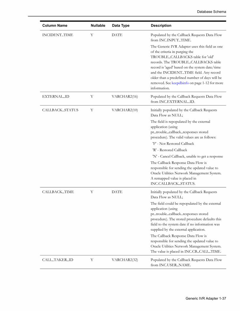
Database Schema
INCIDENT_TIME Y DATE Populated by the Callback Requests Data Flow from INC.INPUT_TIME.
The Generic IVR Adapter uses this field as one of the criteria in purging the TROUBLE_CALLBACKS table for 'old' records. The TROUBLE_CALLBACKS table record is 'aged' based on the system date/time and the INCIDENT_TIME field. Any record older than a predefined number of days will be removed. See keepdbinfo on page 1-12 for more information.
EXTERNAL_ID Y VARCHAR2(16) Populated by the Callback Requests Data Flow from INC.EXTERNAL_ID.
CALLBACK_STATUS Y VARCHAR2(10) Initially populated by the Callback Requests Data Flow as NULL;
The field is repopulated by the external application (using pr_trouble_callback_responses stored procedure). The valid values are as follows:
'F' - Not Restored Callback
'R' - Restored Callback
'N' - Cancel Callback, unable to get a response
The Callback Response Data Flow is responsible for sending the updated value to Oracle Utilities Network Management System. A remapped value is placed in INC.CALLBACK_STATUS.
CALLBACK_TIME Y DATE Initially populated by the Callback Requests Data Flow as NULL;
The field could be repopulated by the external application (using pr_trouble_callback_responses stored procedure). The stored procedure defaults this field to the system date if no information was supplied by the external application.
The Callback Response Data Flow is responsible for sending the updated value to Oracle Utilities Network Management System. The value is placed in INC.CB_CALL_TIME.
CALL_TAKER_ID Y VARCHAR2(32) Populated by the Callback Requests Data Flow from INC.USER_NAME.
Column Name Nullable Data Type Description
Generic IVR Adapter 1-37
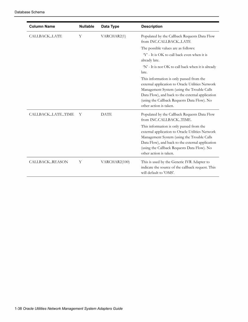
Database Schema
CALLBACK_LATE Y VARCHAR2(1) Populated by the Callback Requests Data Flow from INC.CALLBACK_LATE
The possible values are as follows:
‘Y’ - It is OK to call back even when it is already late.
‘N’ - It is not OK to call back when it is already late.
This information is only passed from the external application to Oracle Utilities Network Management System (using the Trouble Calls Data Flow), and back to the external application (using the Callback Requests Data Flow). No other action is taken.
CALLBACK_LATE_TIME Y DATE Populated by the Callback Requests Data Flow from INC.CALLBACK_TIME.
This information is only passed from the external application to Oracle Utilities Network Management System (using the Trouble Calls Data Flow), and back to the external application (using the Callback Requests Data Flow). No other action is taken.
CALLBACK_REASON Y VARCHAR2(100) This is used by the Generic IVR Adapter to indicate the source of the callback request. This will default to 'OMS'.
Column Name Nullable Data Type Description
1-38 Oracle Utilities Network Management System Adapters Guide

Database Schema
PROCESS_STATUS Y VARCHAR2(1) Initially populated by the Callback Requests Data Flow as 'N', signifying that the record is a new callback
Once the record was fetched by the external application (using pr_trouble_callback_requests stored procedure), the field is automatically updated by the stored procedure to 'I' signifying that the external system is currently processing the callback response.
As soon as the external application successfully returns the callback response to the Generic IVR Adapter (using pr_trouble_callback_responses stored procedure), the field is updated to 'C', signifying that the external application has completed the processing of the callback response.
This field is internally maintained by the Generic IVR Adapter. Below is a list of valid values for this field.
'N' - New Callback
'I' - In Processing Of Callback Response
'C' - Completed The Processing Of Callback Response
The Generic IVR Adapter uses this field as one of the criteria in purging the TROUBLE_CALLBACKS table for 'old' records. Records with PROCESS_STATUS field = 'C' will be purged.
CALLBACK_DONE Y VARCHAR2(1) Initially populated by the Callback Requests Data Flow as 'N', signifying that the callback is not yet done.
As soon as the external application successfully returns the callback response to the Generic IVR Adapter (using pr_trouble_callback_responses stored procedure), the field is updated to 'Y', signifying that the callback has been done.
Below is a list of valid values for this field.
'N' - Callback Has Not Been Done
'Y' - Callback Has Been Done
The Generic IVR Adapter uses this field as one of the criteria in purging the TROUBLE_CALLBACKS table for 'old' records. Records with CALLBACK_DONE field = 'Y' will be purged.
Column Name Nullable Data Type Description
Generic IVR Adapter 1-39

Database Schema
CAUSE_CODE Y VARCHAR2(32) This is used to relay back to customers the cause of an outage when a callback is performed.
Populated by the Callback Requests Data Flow from JOBS.CAUSE when the useExternalCause rule is set to ‘yes’ in the SRS_RULES.
OUTAGE_DURATION Y NUMBER Outage duration in seconds.
Populated by the Callback Requests Data with the difference between JOBS.RESTORE_TIME and JOBS.BEGIN_TIME.
CUSTOMER_COUNT Y NUMBER Populated by the Callback Requests Data Flow from INC.USER_NAME.
CB_DETAIL_1 Y VARCHAR2(80) Populated by the Callback Requests Data Flow from a column in the PICKLIST_INFO_UPD_TR database table. Column name is configured in the IVR_ADAPTER_CONFIG database table.
CB_DETAIL_2 Y VARCHAR2(80) Populated by the Callback Requests Data Flow from a column in the PICKLIST_INFO_UPD_TR database table. Column name is configured in the IVR_ADAPTER_CONFIG database table.
CB_DETAIL_3 Y VARCHAR2(80) Populated by the Callback Requests Data Flow from a column in the PICKLIST_INFO_UPD_TR database table. Column name is configured in the IVR_ADAPTER_CONFIG database table.
CB_DETAIL_4 Y VARCHAR2(80) Populated by the Callback Requests Data Flow from a column in the PICKLIST_INFO_UPD_TR database table. Column name is configured in the IVR_ADAPTER_CONFIG database table.
Column Name Nullable Data Type Description
1-40 Oracle Utilities Network Management System Adapters Guide

Database Schema
Stored Procedure Parameters
pk_ccb.submit_callData structures and parameters of the PK_CCB.SUBMIT_CALL stored procedure:
SUBTYPE udf_field IS VARCHAR2(256);TYPE input_call_rec IS RECORD ( call_source_id VARCHAR2(3), service_point_id trouble_calls.cust_id%TYPE, external_id trouble_calls.external_id%TYPE, account_number trouble_calls.cust_key%TYPE, trouble_code trouble_calls.cust_trouble_code%TYPE, first_name trouble_calls.cust_first_name%TYPE, last_name trouble_calls.cust_last_name%TYPE, phone trouble_calls.cust_phone%TYPE, phone_area trouble_calls.cust_phone_area%TYPE, alt_phone trouble_calls.alternate_phone%TYPE, priority trouble_calls.cust_priority%TYPE, critical_flag trouble_calls.cust_critical%TYPE, life_support_flag trouble_calls.cust_life_support%TYPE, call_id trouble_calls.general_area%TYPE, call_time trouble_calls.call_time%TYPE, call_comment trouble_calls.call_comment%TYPE, call_taker trouble_calls.usename%TYPE, call_type trouble_calls.call_type%TYPE, addr_building trouble_calls.addr_building%TYPE, addr_street trouble_calls.addr_street%TYPE, addr_cross_street trouble_calls.addr_street%TYPE, addr_city_state trouble_calls.addr_city%TYPE, drive_instr trouble_calls.drv_inst%TYPE, meet_time trouble_calls.meet_time%TYPE, meet_type trouble_calls.meet_type%TYPE, group_by_name trouble_calls.group_by_name%TYPE, device_id trouble_calls.cust_device_alias%TYPE, meter_id trouble_calls.meter_id%TYPE, trouble_queue trouble_calls.cust_trouble_queue%TYPE, trouble_location trouble_calls.trouble_loc%TYPE, x_coord trouble_calls.x_ref%TYPE, y_coord trouble_calls.y_ref%TYPE, appt_type trouble_calls.appt_type%TYPE, appt_time trouble_calls.appt_time%TYPE, appt_range trouble_calls.appt_range%TYPE, callback_flag trouble_calls.callback_request%TYPE, callback_before_time trouble_calls.callback_time%TYPE, callback_late_flag trouble_calls.callback_late%TYPE, intersection_cls trouble_calls.cust_device_cls%TYPE, intersection_idx trouble_calls.cust_device_idx%TYPE, cancel_flag trouble_calls.cust_call_cancel%TYPE, update_flag trouble_calls.update_existing_inc%TYPE, udf1 udf_field, udf2 udf_field, udf3 udf_field, udf4 udf_field, udf5 udf_field);
Generic IVR Adapter 1-41

Database Schema
-- new/updated trouble call PROCEDURE submit_call ( p_call IN input_call_rec, p_err_no OUT NUMBER, p_err_msg OUT VARCHAR2);
Description of the parameters of the PK_CCB.SUBMIT_CALL stored procedure.
Parameter Name Parameter Type Description
p_call.call_source_id VARCHAR2(2) Id unique to the call capture mechanism (always set to 2 for CCB, 3 for IVR - for example), Value will be prefixed to p_call.external_id field in this stored procedure. Used to allow NMS to maintain unique call ids (incidents.external_id) across multiple call taking systems submitting independent (overlapping) sets of external_ids. Generally an integer (to better support Interactive Voice Response systems) - but can be project specific.
p_call.service_point_id VARCHAR2(64) Service point id.
p_call.external_id VARCHAR2(16) Call external id unique ID from call capture system (CCB). To ensure uniqueness a given NMS implementation needs to agree on a fixed length field (12 characters for example).
p_call. account_number VARCHAR2(30) Customer account number.
p_call.trouble_code VARCHAR2(32) Call trouble code. Integer passed as a string - each character (0-9) indicates a specific selection (or 0 for non-selection) from each of 1 to 32 different trouble call categories. Project configurable.
p_call.first_name VARCHAR2(75) Customer first name or full name (if customer name is passed in a single field).
p_call.last_name VARCHAR2(75) Customer last name.
p_call.phone VARCHAR2(32) Customer phone number.
p_call.phone_area VARCHAR2(8) Customer phone area code.
p_call.alt_phone VARCHAR2(32) Alternative/callback phone number.
p_call.priority VARCHAR2(4) The same value as ces_customers.priority should be passed in. This is used to determine critical customer type.
p_call.critical_flag VARCHAR2(1) Critical customer (Y/N)
p_call.life_support_flag VARCHAR2(1) Life support flag (Y/N).
1-42 Oracle Utilities Network Management System Adapters Guide

Database Schema
p_call.call_id VARCHAR2(32) Call identifier (for example, 911 call id) - mapped to general_area.
p_call.call_time DATE Call capture time from external call capture system
p_call.call_comment VARCHAR2(255) Comments
p_call.call_taker VARCHAR2(32) Call taker id.
p_call.call_type VARCHAR2(8) Call type.
CC&B should leave this field empty.
p_call.addr_building VARCHAR2(10) Building/block number.
p_call.addr_street VARCHAR2(255) Street address or name of the first intersection street.
p_call.addr_cross_street VARCHAR2(255) Name of the second intersection (cross) street.
p_call.addr_city_state VARCHAR2(45) City and (optionally) state.
p_call.drive_instr VARCHAR2(180) Driving instructions.
p_call.meet_time DATE Meet time.
p_call.meet_type NUMBER Meet action code.Possible values:• 0 - for non-meet calls
• 1 - create new meet
• 2 - reschedule existing meet
• 3- cancel existing meet
p_call.group_by_name VARCHAR2(127) Optional control zone name for fuzzy calls.
p_call.device_id VARCHAR2(32) Device alias.
p_call.meter_id VARCHAR2(32) Meter number.
p_call.trouble_queue VARCHAR2(10) Trouble queue (Tree Trimming, Underground, etc)
p_call.trouble_location VARCHAR2(255) Trouble location.
p_call.x_coord NUMBER X coordinate in the NMS electrical network model coordinate system (generally NOT lat/long). If not provided JMService will default to the coordinates for the supply_node from the point_coordinates table.
p_call.y_coord NUMBER Y coordinate - match for X coordinate above.
p_call.appt_type NUMBER Appointment type.
Parameter Name Parameter Type Description
Generic IVR Adapter 1-43
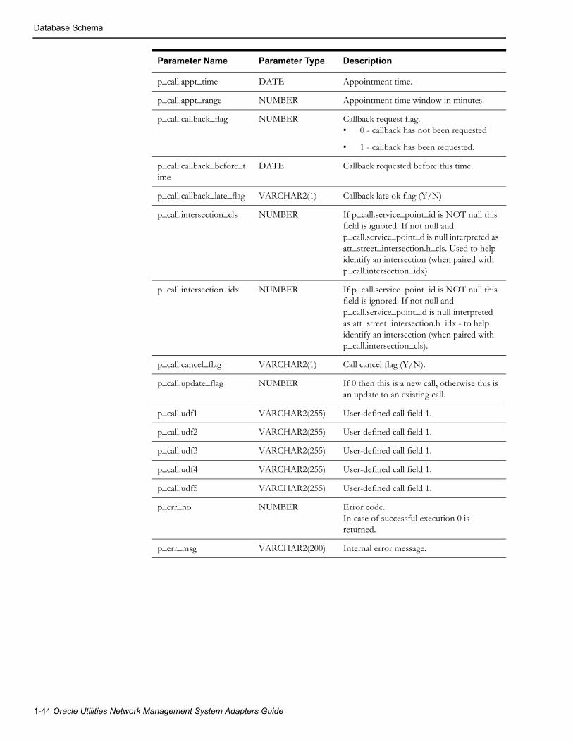
Database Schema
p_call.appt_time DATE Appointment time.
p_call.appt_range NUMBER Appointment time window in minutes.
p_call.callback_flag NUMBER Callback request flag.• 0 - callback has not been requested
• 1 - callback has been requested.
p_call.callback_before_time
DATE Callback requested before this time.
p_call.callback_late_flag VARCHAR2(1) Callback late ok flag (Y/N)
p_call.intersection_cls NUMBER If p_call.service_point_id is NOT null this field is ignored. If not null and p_call.service_point_d is null interpreted as att_street_intersection.h_cls. Used to help identify an intersection (when paired with p_call.intersection_idx)
p_call.intersection_idx NUMBER If p_call.service_point_id is NOT null this field is ignored. If not null and p_call.service_point_id is null interpreted as att_street_intersection.h_idx - to help identify an intersection (when paired with p_call.intersection_cls).
p_call.cancel_flag VARCHAR2(1) Call cancel flag (Y/N).
p_call.update_flag NUMBER If 0 then this is a new call, otherwise this is an update to an existing call.
p_call.udf1 VARCHAR2(255) User-defined call field 1.
p_call.udf2 VARCHAR2(255) User-defined call field 1.
p_call.udf3 VARCHAR2(255) User-defined call field 1.
p_call.udf4 VARCHAR2(255) User-defined call field 1.
p_call.udf5 VARCHAR2(255) User-defined call field 1.
p_err_no NUMBER Error code.In case of successful execution 0 is returned.
p_err_msg VARCHAR2(200) Internal error message.
Parameter Name Parameter Type Description
1-44 Oracle Utilities Network Management System Adapters Guide

Database Schema
pk_ccb.job_historyStored procedure PK_CCB.JOB_HISTORY allows caller to retrieve list of jobs matching passed in search condition.
The following types of search conditions are supported:
• Search for specific customer by service point id, premise id or account number.
• Location-based search. Search for jobs at or nearby specified location. Location can be street intersection or street segment (block).
• Fuzzy outage search. Search for fuzzy jobs by external id, call identifier, caller name or caller phone.
• Custom search. To use custom search the stored procedure has to be modified by the project. Additional search parameters are passed in the 'p_custom' field.
CREATE OR REPLACE TYPE customer_search_obj AS OBJECT ( serv_point_id VARCHAR2(64), premise_id NUMBER, account_number VARCHAR2(30))
CREATE OR REPLACE TYPE location_search_obj AS OBJECT ( city VARCHAR2(200), state VARCHAR2(30), street1 VARCHAR2(200), street2 VARCHAR2(200), block_number NUMBER)
CREATE OR REPLACE TYPE fuzzy_search_obj AS OBJECT ( external_id VARCHAR2(200), call_id VARCHAR2(200), caller_name VARCHAR2(200), caller_phone VARCHAR2(200))
CREATE OR REPLACE TYPE custom_search_obj AS OBJECT ( field1 VARCHAR2(200), field2 VARCHAR2(200), field3 VARCHAR2(200), field4 VARCHAR2(200), field5 VARCHAR2(200))
TYPE nms_cursor IS REF CURSOR;
-- Get job history.PROCEDURE job_history ( p_cust IN customer_search_obj, p_loc IN location_search_obj, p_fuzzy IN fuzzy_search_obj, p_custom IN custom_search_obj, p_num_days IN NUMBER, p_jobs OUT nms_cursor, p_err_no OUT NUMBER, p_err_msg OUT VARCHAR2);
Generic IVR Adapter 1-45

Database Schema
Description of the parameters of the PK_CCB.JOB_HISTORY stored procedure.
For each returned job the following information is included.
TYPE job_rec IS RECORD ( serv_point_id ces_customers.id%TYPE, serv_point_addr ces_customers.address%TYPE, event_idx jobs.event_idx%TYPE, begin_time jobs.begin_time%TYPE, est_rest_time jobs.est_rest_time%TYPE, est_rest_time_source jobs.est_source%TYPE, restore_time jobs.restore_time%TYPE,
Parameter Name Parameter Type Description
p_cust.serv_point_id
VARCHAR2(64) Service point id.
p_cust.premise_id NUMBER Service location (premise id).
p_cust.account_number
VARCHAR2(30) Customer account number.
p_loc.city VARCHAR2(200) City.
p_loc.state VARCHAR2(30) State.
p_loc.street1 VARCHAR2(200) Street name. This field is used in both street intersection search and street segment search.
p_loc.street2 VARCHAR2(200) Second street name for street intersection search.
p_loc.block_number
NUMBER Block number for street segment search.
p_fuzzy.external_id VARCHAR2(200) Call external id.
p_fuzzy.call_id VARCHAR2(200) Call identifier (for example, id for 911 calls).
p_fuzzy.caller_name
VARCHAR2(200) Caller name.
p_fuzzy.caller_phone
VARCHAR2(200) Caller phone number.
p_custom.xxx Implementation-defined search parameters.
p_cmp_days NUMBER If greater than 0 then switching plans completed within specified number of days in the past will be returned in addition to current and future switching plans.
p_jobs nms_cursor Returned jobs information.
p_err_no NUMBER Error code.In case of successful execution 0 is returned.
p_err_msg VERCHAR2(200) Internal error message.
1-46 Oracle Utilities Network Management System Adapters Guide

Database Schema
cust_out jobs.num_cust_out%TYPE, comments jobs.operator_comment%TYPE, alarm_state jobs.alarm_state%TYPE, alarm_state_desc te_valid_states.description%TYPE, trouble_location jobs.display_name%TYPE, status jobs.status%TYPE, device_class jobs.devcls_name%TYPE, trouble_code jobs.trouble_code%TYPE, feeder_name jobs.feeder_name%TYPE, cause jobs.cause%TYPE, description jobs.description%TYPE, referral_group jobs.referral_group%TYPE, last_update_time jobs.last_update_time%TYPE, udf1 udf_field, udf2 udf_field, udf3 udf_field, udf4 udf_field, udf5 udf_field);
Field Name Field Type Description
serv_point_id VARCHAR2(64) Service point id.
serv_point_addr VARCHAR2(200) Service point address
event_idx NUMBER Event index.
begin_time DATE Outage begin time.
est_rest_time DATE Estimated restoration time (ERT).
est_rest_time_source
VARCHAR2(1) ERT source. Possible values:• N - no ERT
• I - Initial ERT
• C - manually entered ERT (from crew or NMS operator)
• S - ERT calculated by Storm Management
• O - ERT calculated by Storm Management (crew on-site)
• P - Non-publisher ERT
• G - ERT override is in effect
• D - ERT delay is in effect
restore_time DATE Outage restoration time.
cust_out NUMBER Number of customers affected by the outage.
comments VARCHAR2(255) Operator's comment. Note some customers increase this to max allowed (4k).
alarm_state VARCHAR2(32) Outage state.
Generic IVR Adapter 1-47

Database Schema
alarm_state_desc VARCHAR2(80) Description of the outage state.
trouble_location VARCHAR2(255)
status NUMBER Job type.Possible values:• 0 - Fuzzy outage.
• 1 - Probable/predicted service outage.
• 2 - Probable/predicted device outage.
• 3 - Real service outage.
• 4 - Real device outage.
• 7 - Non-outage.
• 8 - Critical meet.
• 9 - Future meet.
• 10 - Confirmed service outage.
• 11 - Confirmed secondary outage.
• 13 - Probable/predicted momentary outage.
• 14 - Real momentary outage.
• 15 - Planned outage.
• 16 - Non-electric event.
• 17 - Master switching job.
• 18 - Fault current event.
device_class VARCHAR2(32) Outage device class name (e.g., fuse)
trouble_code VARCHAR2(128) Trouble code.
feeder_name VARCHAR2(32) Feeder name.
cause VARCHAR2(32) Outage cause.
description VARCHAR2(128) Job description.
referral_group VARCHAR2(32) Referral group.
last_update_time DATE Timestamp of the latest update to the outage record.
udf1 VARCHAR2(255) Job user-defined field 1.
udf2 VARCHAR2(255) Job user-defined field 2.
udf3 VARCHAR2(255) Job user-defined field 3.
udf4 VARCHAR2(255) Job user-defined field 4.
udf5 VARCHAR2(255) Job user-defined field 5.
Field Name Field Type Description
1-48 Oracle Utilities Network Management System Adapters Guide

Database Schema
pk_ccb.call_historyStored procedure PK_CCB.CALL_HISTORY will allow caller to retrieve list of calls matching search condition.
Following types of search conditions will be supported:
• Search for calls for a specific customer by service point id, premise id or account number.
• Location-based search. Search for calls at or nearby specified location. Location can be street intersection or street segment (block).
• Fuzzy outage search. Search for fuzzy calls by external id, call identifier, caller name or caller phone.
Custom search. To use custom search the stored procedure has to be modified by the project. Additional search parameters are passed in the 'p_custom' field.
PROCEDURE call_history ( p_cust IN customer_search_obj, p_loc IN location_search_obj, p_fuzzy IN fuzzy_search_obj, p_custom IN custom_search_obj, p_num_days IN NUMBER, p_calls OUT nms_cursor, p_err_no OUT NUMBER, p_err_msg OUT VARCHAR2);
For each returned call the following information is included.
-- call history recordTYPE call_rec IS RECORD ( external_id incidents.external_id%TYPE, call_id incidents.general_area%TYPE, serv_point_id incidents.cid%TYPE, call_time incidents.input_time%TYPE, address incidents.address%TYPE, short_desc incidents.short_desc%TYPE, comments incidents.op_comment%TYPE, call_taker incidents.user_name%TYPE, cust_name incidents.customer_name%TYPE, status incidents.active%TYPE, udf1 udf_field, udf2 udf_field, udf3 udf_field, udf4 udf_field, udf5 udf_field);
Field Name Field Type Description
external_id VARCHAR2(16) Call external id.
call_id VARCHAR2(32) Call identifier (for example, id for 911 calls).
serv_point_id VARCHAR2(64) Service point id.
call_time DATE Call time.
Address VARCHAR2(255) Address for the call.
Generic IVR Adapter 1-49
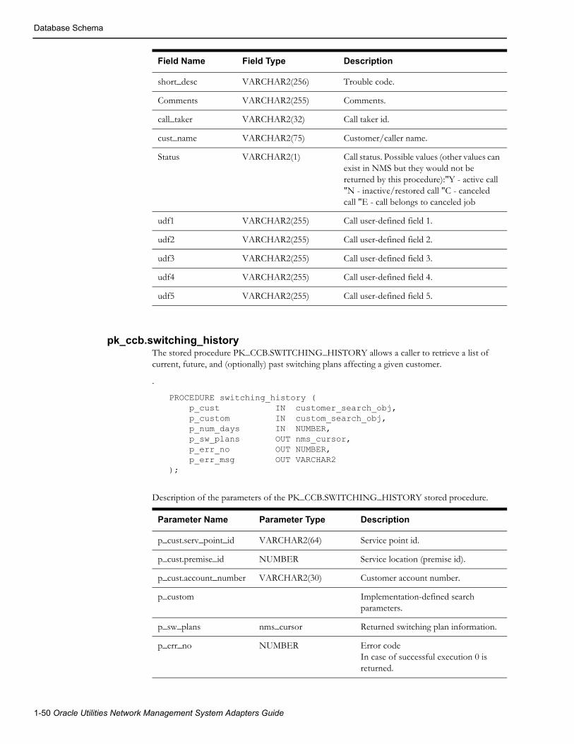
Database Schema
pk_ccb.switching_historyThe stored procedure PK_CCB.SWITCHING_HISTORY allows a caller to retrieve a list of current, future, and (optionally) past switching plans affecting a given customer.
.
PROCEDURE switching_history ( p_cust IN customer_search_obj, p_custom IN custom_search_obj, p_num_days IN NUMBER, p_sw_plans OUT nms_cursor, p_err_no OUT NUMBER, p_err_msg OUT VARCHAR2);
Description of the parameters of the PK_CCB.SWITCHING_HISTORY stored procedure.
short_desc VARCHAR2(256) Trouble code.
Comments VARCHAR2(255) Comments.
call_taker VARCHAR2(32) Call taker id.
cust_name VARCHAR2(75) Customer/caller name.
Status VARCHAR2(1) Call status. Possible values (other values can exist in NMS but they would not be returned by this procedure):"Y - active call "N - inactive/restored call "C - canceled call "E - call belongs to canceled job
udf1 VARCHAR2(255) Call user-defined field 1.
udf2 VARCHAR2(255) Call user-defined field 2.
udf3 VARCHAR2(255) Call user-defined field 3.
udf4 VARCHAR2(255) Call user-defined field 4.
udf5 VARCHAR2(255) Call user-defined field 5.
Field Name Field Type Description
Parameter Name Parameter Type Description
p_cust.serv_point_id VARCHAR2(64) Service point id.
p_cust.premise_id NUMBER Service location (premise id).
p_cust.account_number VARCHAR2(30) Customer account number.
p_custom Implementation-defined search parameters.
p_sw_plans nms_cursor Returned switching plan information.
p_err_no NUMBER Error codeIn case of successful execution 0 is returned.
1-50 Oracle Utilities Network Management System Adapters Guide

Database Schema
For each returned switching plan following information is included.
-- switching plan recordTYPE switching_plan_rec IS RECORD ( plan_class swman_sheet_cls.switch_sheet_type%TYPE, plan_number swman_sheet.switch_sheet_idx%TYPE, start_date swman_sheet.start_date%TYPE, end_date swman_sheet.finish_date%TYPE, device_alias swman_sheet.device_alias%TYPE, state te_valid_states.state_name%TYPE, work_district swman_sheet_extn.string_value%TYPE, work_location swman_sheet_extn.string_value%TYPE, work_description swman_sheet_extn.string_value%TYPE, serv_point_id ces_customers.id%TYPE, serv_point_addr ces_customers.address%TYPE, udf1 udf_field, udf2 udf_field, udf3 udf_field, udf4 udf_field, udf5 udf_field, udf6 udf_field, udf7 udf_field, udf8 udf_field, udf9 udf_field, udf10 udf_field);
p_err_msg VARCHAR2(200) Error message.
Field Name Field Type Description
plan_class VARCHAR2(32) Switching plan type (planned, emergency, ….).
plan_number NUMBER Switching plan number.
start_date DATE Switching plan start date.
end_date DATE Switching plan end date.
State VARCHAR2(32) Switching plan state.
work_district VARCHAR2(500)
work_location VARCHAR2(500)
work_description VARCHAR2(500)
serv_point_id VARCHAR2(64) Service point id.
serv_point_addr VARCHAR2(200) Service point address
Parameter Name Parameter Type Description
Generic IVR Adapter 1-51

Database Schema
pk_ccb.trouble_code_configStored procedure PK_CCB.TROUBLE_CODE_CONFIG allows caller to retrieve list of trouble codes configured in the Oracle Utilities Network Management System.
PROCEDURE trouble_code_config ( p_trouble_codes OUT nms_cursor, p_err_no OUT NUMBER, p_err_msg OUT VARCHAR2);
For each returned trouble code following information is included:
-- trouble code configuration recordTYPE trouble_code_rec IS RECORD ( group_name srs_trouble_codes.group_name%TYPE, group_order srs_trouble_codes.group_order%TYPE, code_name srs_trouble_codes.code_name%TYPE, code_num srs_trouble_codes.code_num%TYPE, short_desc srs_trouble_codes.short_desc%TYPE, description srs_trouble_codes.description%TYPE);
Field Name Field Type Description
p_trouble_codes nms_cursor Returned trouble code information.
p_err_no NUMBER Error codeIn case of successful execution 0 is returned.
p_err_msg VARCHAR2(200) Error message
Field Name Field Type Description
group_name VARCHAR2(20) Trouble code group name
group_order NUMBER Trouble code group order
code_name VARCHAR2(40) Trouble code name
code_num NUMBER Trouble code number within its group
short_desc VARCHAR2(25) Short description of the trouble code
description VARCHAR2(70) Long description of the trouble code
1-52 Oracle Utilities Network Management System Adapters Guide

Database Schema
pr_trouble_callsThe Generic IVR Adapter provides the pr_trouble_calls procedure to be used by the external application to insert trouble calls in the TROUBLE_CALLS table. Refer to Trouble Calls on page 1-4 for Data Flow details.
Below is a high level description of what is done inside the stored procedure
• Upon invoking the stored procedure, the p_premise_id parameter is used to query the CES_CUSTOMERS table (via the SERV_LOC_ID field) to retrieve the ACCOUNT_NUMBER, H_CLS and H_IDX fields of the said table. The value of these fields is placed in the corresponding columns of the TROUBLE_CALLS table.
• Other parameter values are inserted to corresponding fields on the TROUBLE_CALL table.
• Several TROUBLE_CALLS columns will have default value when no parameter value is supplied.
• Should there be an error in the record insert, an Oracle error is returned.
Note: If the given premise id has multiple accounts associated with it, only one account (i.e., the first account) is used.
Generic IVR Adapter 1-53

Database Schema
Below are details about each parameter of the pr_trouble_calls stored procedure. Note that the field name column indicates the corresponding column that is populated in the TROUBLE_CALLS table.
Parameters
Parameter Direction Data Type Field Name Comment
p_premise_id In VARCHAR2 PREMISE_ID The value is inserted as is.
p_trouble_code In VARCHAR2 TROUBLE_CODE Defaults to ‘1’ followed by a certain number of ‘0’. If no value was supplied. The total length of the string is the total number of distinct groups in the SRS_TROUBLE_CODES table.
p_callback_ind In VARCHAR2 CALLBACK_INDICATOR The possible values are as follows:
‘0’ - callback not requested
‘1’ - callback requested
Defaults to ‘1’ if no value is supplied.
‘Y’ is translated to ‘1’.
‘N’ is translated to ‘0’.
p_call_time In DATE CALL_TIME Defaults to the database system date if no value is supplied
p_call_taker_id In VARCHAR2 CALL_TAKER_ID The value is inserted as is.
p_alternate_phone In VARCHAR2 ALTERNATE_PHONE The value is inserted as is.
p_customer_comment In VARCHAR2 CUSTOMER_COMMENT The value is inserted as is.
p_customer_phone In VARCHAR2 CUSTOMER_PHONE The value is inserted as is.
p_customer_name In VARCHAR2 CUSTOMER_NAME The value is inserted as is.
p_customer_address In VARCHAR2 CUSTOMER_ADDRESS The value is inserted as is.
p_customer_city_state In VARCHAR2 CUSTOMER_CITY_STATE The value is inserted as is.
p_customer_priority In VARCHAR2 CUSTOMER_PRIORITY The value is inserted as is.
p_external_id In VARCHAR2 EXTERNAL_ID The value is inserted as is.
p_device_alias In VARCHAR2 DEVICE_ALIAS The value is inserted as is.
1-54 Oracle Utilities Network Management System Adapters Guide

Database Schema
p_check_cutoff_ind In VARCHAR2 CHECK_CUTOFF_IND The possible values are as follows:
‘Y’ - check if the customer is disconnected
‘N’ - do not perform checking.
Defaults to ‘N’ if no value is supplied
p_callback_late_ind In VARCHAR2 CALLBACK_LATE_IND The possible values are as follows:
‘Y’ - It is OK to call back even when it is already late.
‘N’ - It is not OK to call back when it is already late.
Defaults to ‘N’ if no value is supplied
p_callback_before_time In DATE CALLBACK_BEFORE_TIME The value is inserted as is.
p_trouble_queue In VARCHAR2 TROUBLE_QUEUE The value is inserted as is.
p_meter_id In VARCHAR2 METER_ID The value is inserted as is.
p_supply_id In NUMBER SUPPLY_ID The value is inserted as is.
p_cust_phone_area In VARCHAR2 CUST_PHONE_AREA The value is inserted as is.
p_cust_last_name In VARCHAR2 CUST_LAST_NAME The value is inserted as is.
p_general_area In VARCHAR2 GENERAL_AREA The value is inserted as is.
p_cust_order_num In VARCHAR2 CUST_ORDER_NUM The value is inserted as is.
p_drv_inst In VARCHAR2 DRV_INST The value is inserted as is.
p_cust_life_support In VARCHAR2 CUST_LIFE_SUPPORT The value is inserted as is.
p_cust_call_cancel In VARCHAR2 CUST_CALL_CANCEL The value is inserted as is.
p_short_desc In VARCHAR2 SHORT_DESC The value is inserted as is.
p_addr_building In VARCHAR2 ADDR_BUILDING The value is inserted as is.
p_meet_time In DATE MEET_TIME The value is inserted as is.
p_meet_type In NUMBER MEET_TYPE The value is inserted as is.
p_groupable In NUMBER GROUPABLE The value is inserted as is.
p_clue In NUMBER CLUE The value is inserted as is.
p_combine_pri In NUMBER COMBINE_PRI The value is inserted as is.
p_cust_status In NUMBER CUST_STATUS The value is inserted as is.
p_cust_intr_x In NUMBER CUST_INTR_X The value is inserted as is.
Parameter Direction Data Type Field Name Comment
Generic IVR Adapter 1-55

Database Schema
Note: The pr_trouble_calls stored procedure does not require a call status parameter from the user to insert in the TROUBLE_CALLS stored procedure. Each time the stored procedure inserts trouble calls in the TROUBLE_CALLS table, the CALL_STATUS field is always ‘N’, signifying that it is a new trouble call.
p_cust_intr_y In NUMBER CUST_INTR_Y The value is inserted as is.
p_cust_intersect_cls In NUMBER CUST_INTERSECT_CLS The value is inserted as is.
p_cust_intersect_idx In NUMBER CUST_INTERSECT_IDX The value is inserted as is.
p_cust_intersect_ncg In NUMBER CUST_INTERSECT_NCG The value is inserted as is.
p_update_existing_inc In NUMBER UPDATE_EXISTING_INC The value is inserted as is.
p_fuzzy_ncg_cls In NUMBER FUZZY_NCG_CLS The value is inserted as is.
p_fuzzy_ncg_idx In NUMBER FUZZY_NCG_IDX The value is inserted as is.
p_group_by_name In VARCHAR2 GROUP_BY_NAME The value is inserted as is.
p_cust_critical In VARCHAR2 CUST_CRITICAL The value is inserted as is.
p_related_evt_cls In NUMBER RELATED_EVT_CLS The value is inserted as is.
p_related_evt_idx In NUMBER RELATED_EVT_IDX The value is inserted as is.
p_related_evt_app In NUMBER RELATED_EVT_APP The value is inserted as is.
p_x_ref In NUMBER X_REF The value is inserted as is.
p_y_ref In NUMBER Y_REF The value is inserted as is.
p_call_type In VARCHAR2 CALL_TYPE The value is inserted as is.
p_cust_phone_update In VARCHAR2 CUST_PHONE_UPDATE The value is inserted as is.
p_trouble_loc In VARCHAR2 TROUBLE_LOC The value is inserted as is.
p_appt_type In VARCHAR2 APPT_TYPE The value is inserted as is.
p_appt_time In DATE APPT_TIME The value is inserted as is.
p_appt_range In NUMBER APPT_RANGE The value is inserted as is.
p_cust_device_ncg In NUMBER CUST_DEVICE_NCG The value is inserted as is.
p_cust_device_partition In NUMBER CUST_DEVICE_PARTITION The value is inserted as is.
p_err_premise_id Out VARCHAR2 VARCHAR2(80) The erroneous premise ID input parameter
p_err_oracle_error Out VARCHAR2 VARCHAR2(80) Oracle’s error message.
Parameter Direction Data Type Field Name Comment
1-56 Oracle Utilities Network Management System Adapters Guide

Database Schema
pr_trouble_callback_requestsBelow is a high level description of what is done inside the stored procedure
• From the TROUBLE_CALLBACKS table, a list of new callback requests is created. These are the TROUBLE_CALLBACKS records whose PROCESS_STATUS field is ‘N’ (New) and CALLBACK_DONE field is ‘N’ (No).
• The list is captured within the stored procedure as a database cursor and returned to the calling application.
• The PROCESS_STATUS field of the records in the list is updated from ‘N’ (New) to ‘I’ (In Progress).
Note: Refer to the Data Flow Steps of the Callback Requests Data Flow on how the TROUBLE_CALLBACKS table is populated.
Parameter
Cursor DefinitionBelow are the fields of the CALLBACK_CURSOR. Take note that the CALLBACK_CURSOR is defined as a weakly typed cursor.
Parameter Direction Cursor
p_callback_requests In/Out CALLBACK_CURSOR
Field Name from the Cursor
Data TypeField Name from TROUBLE_CALLBACKS
Comments
EVENT_CLS NUMBER(38) TCB.EVENT_CLS Event class
EVENT_IDX NUMBER(38) TCB.EVENT_IDX Event index
INCIDENT_NUMB NUMBER(38) TCB.INCIDENT_NUMB Incident number
PREMISE_ID VARCHAR2(50) TCB.PREMISE_ID Premise id
CUSTOMER_NAME VARCHAR2(75) TCB.CUSTOMER_NAME Customer name
CUSTOMER_PHONE VARCHAR2(38) TCB.CUSTOMER_PHONE Customer phone
CUSTOMER_ADDRESS VARCHAR2(255) TCB.CUSTOMER_ADDRESS Customer address
ALTERNATE_PHONE VARCHAR2(38) TCB.ALTERNATE_PHONE Customer alternate phone number
TROUBLE_CODE VARCHAR2(32) TCB.TROUBLE_CODE This is the trouble code (e.g., ‘10000000’) of the incident rather than the clue (e.g., 'Out'). 'Out' is short for 'All Power Out'.
SHORT_DESCRIPTION VARCHAR2(128) TCB.SHORT_DESCRIPTION This is the clue (e.g., 'Out') of the incident rather than the trouble code (e.g., ‘10000000’). 'Out' is short for 'All Power Out'.
Generic IVR Adapter 1-57
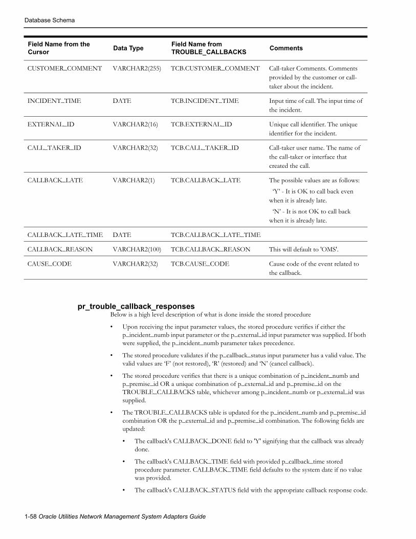
Database Schema
pr_trouble_callback_responsesBelow is a high level description of what is done inside the stored procedure
• Upon receiving the input parameter values, the stored procedure verifies if either the p_incident_numb input parameter or the p_external_id input parameter was supplied. If both were supplied, the p_incident_numb parameter takes precedence.
• The stored procedure validates if the p_callback_status input parameter has a valid value. The valid values are ‘F’ (not restored), ‘R’ (restored) and ‘N’ (cancel callback).
• The stored procedure verifies that there is a unique combination of p_incident_numb and p_premise_id OR a unique combination of p_external_id and p_premise_id on the TROUBLE_CALLBACKS table, whichever among p_incident_numb or p_external_id was supplied.
• The TROUBLE_CALLBACKS table is updated for the p_incident_numb and p_premise_id combination OR the p_external_id and p_premise_id combination. The following fields are updated:
• The callback's CALLBACK_DONE field to 'Y' signifying that the callback was already done.
• The callback's CALLBACK_TIME field with provided p_callback_time stored procedure parameter. CALLBACK_TIME field defaults to the system date if no value was provided.
• The callback's CALLBACK_STATUS field with the appropriate callback response code.
CUSTOMER_COMMENT VARCHAR2(255) TCB.CUSTOMER_COMMENT Call-taker Comments. Comments provided by the customer or call-taker about the incident.
INCIDENT_TIME DATE TCB.INCIDENT_TIME Input time of call. The input time of the incident.
EXTERNAL_ID VARCHAR2(16) TCB.EXTERNAL_ID Unique call identifier. The unique identifier for the incident.
CALL_TAKER_ID VARCHAR2(32) TCB.CALL_TAKER_ID Call-taker user name. The name of the call-taker or interface that created the call.
CALLBACK_LATE VARCHAR2(1) TCB.CALLBACK_LATE The possible values are as follows:
‘Y’ - It is OK to call back even when it is already late.
‘N’ - It is not OK to call back when it is already late.
CALLBACK_LATE_TIME DATE TCB.CALLBACK_LATE_TIME
CALLBACK_REASON VARCHAR2(100) TCB.CALLBACK_REASON This will default to 'OMS'.
CAUSE_CODE VARCHAR2(32) TCB.CAUSE_CODE Cause code of the event related to the callback.
Field Name from the Cursor
Data TypeField Name from TROUBLE_CALLBACKS
Comments
1-58 Oracle Utilities Network Management System Adapters Guide

Database Schema
• Should any of these steps fail, the stored procedure exits and returns the appropriate error.
Note: Refer to the Data Flow Steps of the Callback Response Data Flow on how the TROUBLE_CALLBACKS table is populated.
Parameters
pr_customer_event_detailsThe Generic IVR Gateway provides the pr_customer_event_details stored procedure that gives the event details of an outage given the customer premise. Refer to the data flow detail for Callback Requests on page 1-5.
Below is a high level description of what is done inside the stored procedure.
• The stored procedure tries to get the latest event for the given premise ID (p_in_premise_id input parameter).
ParametersBelow are details about each parameter of the pr_customer_event_details stored procedure.
Parameter Direction Data Type Field Name Comments
p_incident_numb In NUMBER INCIDENT_NUMB Incident Number. Either this or the p_external_id parameter has to be supplied
p_external_id In VARCHAR2 EXTERNAL_ID External Id. Either this or the p_incident_numb parameter has to be supplied
p_premise_id In VARCHAR2 PREMISE_ID Premise Id.
p_callback_status In VARCHAR2 CALLBACK_STATUS The valid values are as follows:
'F' - Not Restored Callback
'R' - Restored Callback
'N' - Cancel Callback, unable to get a response
p_callback_time In DATE CALLBACK_TIME Defaulted to the system date if no value was supplied
p_err_incident_numb Out NUMBER The erroneous incident number input parameter
p_err_external_id Out VARCHAR2 The erroneous external ID input parameter
p_err_premise_id Out VARCHAR2 The erroneous premise ID input parameter
p_err_oracle_error Out VARCHAR2 Oracle’s error message
Generic IVR Adapter 1-59

Database Schema
Parameter Direction Data Type Comments
p_in_premise_id In VARCHAR2 Premise ID input parameter with a corresponding entry in CES_CUSTOMERS.SERV_LOC_ID
p_out_event_class Out NUMBER Event class output parameter
p_out_event_index Out NUMBER Event index output parameter
p_out_outage_status Out VARCHAR2 This is an abbreviation of the current state of the event, for instance, 'NEW', 'ASN', 'CMP', etc.
p_ out_outage_start_time Out DATE The time of the lead call of the job.
p_ out_first_dispatch_time Out DATE The time the first crew was dispatched
p_ out_est_restore_time Out DATE The last estimate of restoration time.
p_ out_est_restore_time_src Out VARCHAR2 The source of the ERT of the event.
Possible values are as follows:
'N' - none (no ERT)
'S' - Storm Management
'P' - Storm Management "non-published global ERT"
'O' - Storm Management "onsite ERT"
'G' - Storm Management "published global ERT"
D' - Storm Management "published global ERT delay"
'C' - User-entered (assumed to have been provided by the crew)
'I' - Initial default ERT
'M' - Storm Management ERT is further in the future then allowed
p_ out_crew_arrival_time Out DATE The time when the crew arrived on location
p_ out_completion_time Out DATE The time the event has been completed. This implies power restoration, the crew(s) are gone, and the event is completed in the Event Details window.
p_ out_restoration_time Out DATE The time that power has been restored.
p_ out_case_note Out VARCHAR2 Comment
p_ out_status Out NUMBER Condition status
p_ out_active Out VARCHAR2 Possible values are as follows:
'Y' - Outage Is Active
'N' - Outage Is Not Active
1-60 Oracle Utilities Network Management System Adapters Guide
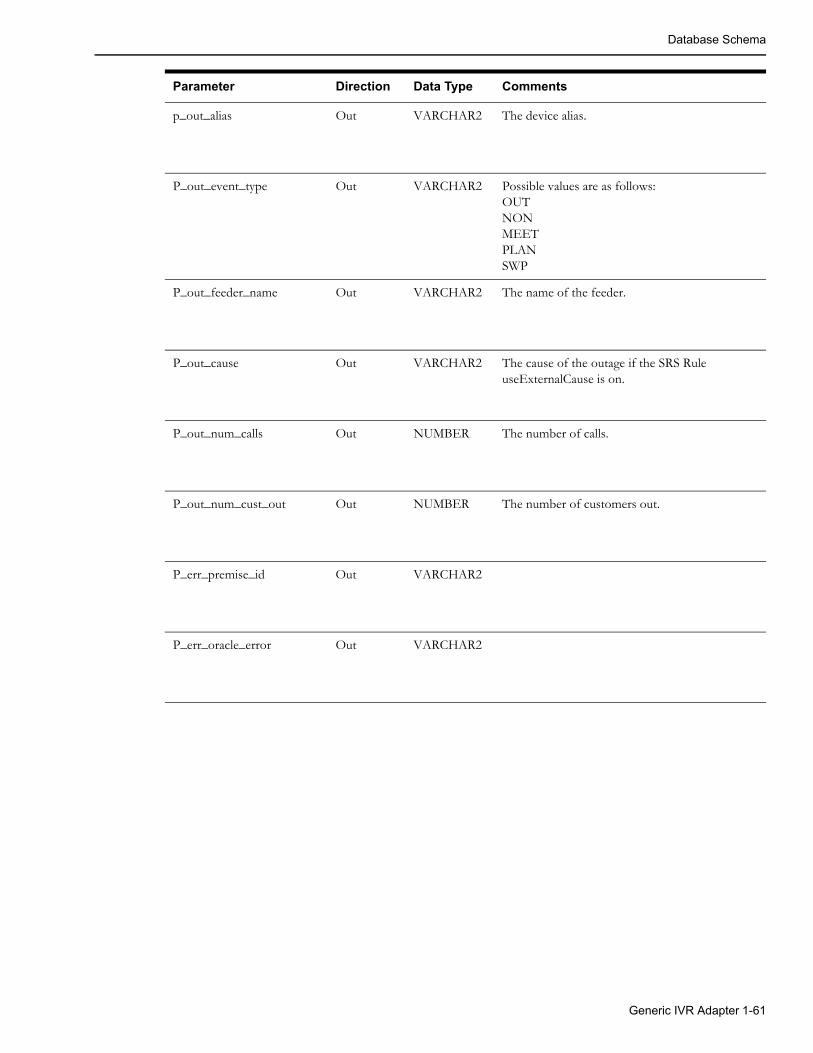
Database Schema
p_out_alias Out VARCHAR2 The device alias.
P_out_event_type Out VARCHAR2 Possible values are as follows:OUTNONMEETPLANSWP
P_out_feeder_name Out VARCHAR2 The name of the feeder.
P_out_cause Out VARCHAR2 The cause of the outage if the SRS Rule useExternalCause is on.
P_out_num_calls Out NUMBER The number of calls.
P_out_num_cust_out Out NUMBER The number of customers out.
P_err_premise_id Out VARCHAR2
P_err_oracle_error Out VARCHAR2
Parameter Direction Data Type Comments
Generic IVR Adapter 1-61

Database Schema
SRSInput Testing Utility Command Line OptionsSRSInput adds raw file incidents into JMService.
Usage SRSinput [-ami][-ami_up] [-max number] [-ivr] [-time] [-blanksok] [-package number]
[-interval seconds] [-divide number] [-tilde] [-debug]
-input filename
Options/Arguments:
Note: If the -ivr option is not used, SRSinput sends calls to JMService via the C++ API.
Option Description
-ami Submit AMI Last Gasp (Power Down) inputs for the meters specified by the -input parameter.
-ami_up Submit AMI Power Up (Restore) inputs for the meters specified by the -input parameter.
-max number Maximum number of calls to enter.
-ivr Write calls to trouble_calls table for IVR adapter.
-time Add input_time with current time.
-blanksok Blank lines in call record are acceptable.
-package number Number of calls to send to JMS at a time. Default: 10.
-interval seconds Seconds to delay between calls.Defaults to 5. Also, it can take floating point values such as 2.5 to sleep 2 and a half seconds between call batches.
-divide number Number to divide <WAIT> times by.
-tilde Use the tilde in column 0 as a call separator.
-debug Enable runtime debugging.
-input filename Filename containing trouble call data. Required.
1-62 Oracle Utilities Network Management System Adapters Guide

Terminology
TerminologyThe following terms and acronyms are relevant to this specification
OMS Outage Management System
NMS Network Management System
CIS Customer Information System
IVR Interactive Voice Response
Generic IVR Adapter A Unix application that generally executes on the OMS server machine. It supports the Trouble Call, Callback Request, and Callback Response Data Flows.
SMService System Monitor Service. SMService monitors the core processes in the system, essentially the services and interfaces.
JMService Job Management Service. The Oracle Utilities Network Management System call processing and outage prediction engine.
ODService Object Directory Service. ODService improves performance of the Oracle Utilities Network Management System by caching large amounts of device information that is likely to be requested by applications. This caching allows the requests to be handled very quickly without directly accessing the database.
Isis Clients access services and tools through a central concurrency management and messaging system called Isis. Isis is a real-time implementation of message oriented middleware and comprises the backbone of the system, providing access to the server for each client and the communication required between tools and services. Isis delivers the organized information to the client applications.
Generic IVR Adapter 1-63

Terminology
1-64 Oracle Utilities Network Management System Adapters Guide

Chapter 2SmallWorld GIS Adapter Template
The Oracle Smallworld data adapter template is a Smallworld Magik code template for an extraction tool to produce .mp files from the Smallworld GIS. This unsupported template is provided as an example for projects to use to facilitate the extraction from the Smallworld GIS to the Oracle Utilities Network Management System (NMS). It is located on the installed Oracle Utilities Network Management System in the $CES_HOME/sdk/gis directory as file SW_EXTRACTOR_TEMPLATE.zip.
SmallWorld GIS Adapter Template 2-1

2-2 Oracle Utilities Network Management System Adapters Guide

Chapter 3ESRI ArcGIS Adapter
Adapter OverviewOracle Network Management System has adapters for various ESRI ArcGIS systems. Please refer to http://support.oracle.com and search the Oracle Support Knowledge Base for “NMS ESRI Extractor” for information on supported versions of the adapter and download links.
Adapter DocumentationOracle Utilities Network Management System ArcGIS adapter documentation is included in the ArcGIS adapter release package.
ESRI ArcGIS Adapter 3-1

Adapter Documentation
3-2 Oracle Utilities Network Management System Adapters Guide
Chapter 4Intergraph G/Electric Adapter
Adapter OverviewOracle Utilities Network Management System has adapters for various Intergraph G/Electric systems. Please refer to http://support.oracle.com and search the Oracle Support Knowledge Base for “NMS Intergraph Extractor” for information on supported versions of the adapter and download links.
Adapter DocumentationOracle Utilities Network Management System Intergraph G/Electric adapter documentation is included in the Intergraph G/Electric adapter release package.
Intergraph G/Electric Adapter 4-1

Adapter Documentation
4-2 Oracle Utilities Network Management System Adapters Guide

Chapter 5Generic IBM MQ Mobile Adapter
This chapter includes the following topics:
• Introduction
• Functional Description
• Adapter Installation
• Design Overview
• Configuration
• DML Reference
• Event Object Fields
IntroductionThis document describes the Generic IBM MQ Mobile Adapter that can be used by Oracle Utilities Network Management System customers to exchange data with external mobile data systems using IBM MQ messages formatted using XML. The reader is assumed to have a working-level knowledge of Oracle Utilities Network Management System mobile data systems, XML, and IBM MQ technologies.
Overview DescriptionIntegration of Oracle Utilities Network Management System to a mobile data system involves the implementation of an adapter process, which exchanges messages with a mobile data system (MDS). The contents of messages sent to the MDS are generated from data obtained from the Oracle Utilities Network Management System services, transformed so that they are suitable for the MDS, and formatted into XML. The contents of messages received from the MDS are extracted from XML, transformed so that they are suitable for Oracle Utilities Network Management System, and sent to the Oracle Utilities Network Management System services.
The current implementation of the adapter supports the exchange of the following types of messages:
• Messages sent to the MDS
• MDS order creation, update and cancellation messages, triggered by Event updates from Oracle Utilities Network Management System.
• Interface communication status verification messages, triggered on a periodic basis.
Generic IBM MQ Mobile Adapter 5-1

Introduction
• Messages received from the MDS
• MDS order update and completion messages, which trigger updates to the corresponding Oracle Utilities Network Management System events.
• Crew log on, update, and log off messages, which trigger Oracle Utilities Network Management System crew creation, update, and de-activation.
• Crew assignment creation, update, and deletion messages, which trigger status changes to the corresponding Oracle Utilities Network Management System crews and events.
• Interface communication status verification messages, which trigger changes to the interface status.
TerminologyThe following terms and acronyms are relevant to this specification
InterSys The middleware infrastructure that supports Oracle Utilities Network Management System
MDS A Mobile Data System that exchanges data with field crews' mobile data terminals.
MDS Order A document or unit of work on the MDS. Also known under different names (for example, "Job").
Event Oracle Utilities Network Management System outage and non-outage events are generated by SRS based on customer calls and changes to the Oracle Utilities Network Management System topology model.
SRS Service Reliability System, the service within InterSys that analyzes and manages outages.
IBM MQ A queue-based messaging system developed by IBM.
XML Extensible Markup Language
DML Dynamic Message Language. This language is used to configure the adapter.
5-2 Oracle Utilities Network Management System Adapters Guide

Functional Description
Functional DescriptionThe purpose of this section is to describe the basic functional capabilities of the Generic IBM MQ Mobile Adapter, as applied to the integration of Oracle Utilities Network Management System with mobile data systems (MDS). While a high-level graphical description is provided here, detailed descriptions are provided in subsequent sections.
Functional RequirementsThe key requirements for the current implementation of the Generic IBM MQ Mobile Adapter are:
• Generation of MDS orders based on Oracle Utilities Network Management System events.
• Updates of MDS orders based on changes to Oracle Utilities Network Management System events.
• Updates to Oracle Utilities Network Management System events based on updates to MDS orders.
• Creation and update of crew information based on changes to crews on the MDS.
• The ability to map multiple events to a single MDS order, based on event relationships in Oracle Utilities Network Management System. This allows groups of events to be viewed as single units of work on the MDS. An example of this is multiple events involved in a set of partial restoration steps.
• The capability to send individual field changes to an order when events change so that there is a minimum usage of the limited bandwidth available to transmit data to and from field crews. This requires storing the data last sent to the MDS so that change detection can be used. This data is saved to the database, so that change detection can be used over an adapter shutdown and restart.
• The ability of data from various Oracle Utilities Network Management System sources to be transformed and combined for transmission to the MDS. The data sources include the Oracle Utilities Network Management System services and the database. Data from the Oracle
Generic IBM MQ Mobile Adapter 5-3
Functional Description
Utilities Network Management System services will be obtained from both asynchronous notification messages and the use of API calls.
• The ability of data from the MDS to be transformed and sent to various Oracle Utilities Network Management System destinations, using database updates and API calls.
Hardware and Software RequirementsThe purpose of this section is to describe the environment relevant to this interface.
Oracle Utilities Network Management System EnvironmentThe Oracle Utilities Network Management System environment consists of a number of servers that are interconnected using the InterSys messaging system.
Adapter ServerThe Generic IBM MQ Mobile Adapter environment may be resident on the same servers as the Oracle Utilities Network Management System services, or it may be implemented on a separate server. Specifications for a stand-alone adapter server:
• All Oracle Utilities Network Management System Unix and Linux operating systems are supported
• IBM MQ messaging product
Notes:
• Queues may reside on a remote machine.
• See the Oracle Utilities Network Management System Licensing Information User Manual for the IBM MQ version requirements.
• A LAN connection to the Oracle Utilities Network Management System server must be available
• Isis must be installed and configured
Oracle Utilities Network Management System ServerThe Oracle Utilities Network Management System server environment is typically deployed on one or more Unix or Linux servers configured with the following:
• Unix/Linux operating system
• Oracle RDBMS with Oracle Utilities Network Management System model
• Oracle Utilities Network Management System service processes
• LAN connection to adapter server
• Message queues to be used by the MQ/XML Adapter appropriately declared in the defined database configuration table.
• Isis
5-4 Oracle Utilities Network Management System Adapters Guide

Functional Description
External System EnvironmentThe external system is any system that can exchange information with Oracle Utilities Network Management System through an adapter. The environment of the external system has the following capabilities:
• Any operating system which supports IBM MQ messaging
• IBM MQ messaging product
• Applications that can request or publish information in a manner which is either directly or indirectly (through a translator) compliant with the XML specifications contained within this document via queues
• Queues must be pre-configured
• IBM MQ Integrator can be used as needed for routing and translation.
Required Installed SoftwareThe following lists the required software that needs to be installed prior to any configuration of the Oracle Utilities Network Management System Generic IBM MQ Mobile Adapter.
• IBM MQ
• Isis (included in the base Oracle Utilities Network Management System installation)
Note: Isis is the messaging backbone for Oracle Utilities Network Management System and will already be present on any Network Management System servers. If the Generic IBM MQ Mobile Adapter is to be executed on a separate server than the Network Management System, then that server must also have Isis installed and running. Every server installation must be running the same version of Isis. The CMM_CELL environment variable must be set the same on any servers which are to communicate through Isis.
Generic IBM MQ Mobile Adapter 5-5
Adapter Installation
Adapter Installation
OverviewThis section is used to guide the user in the installation of the Oracle Utilities Network Management System Generic IBM MQ Mobile Adapter. The following are assumed to be true before the adapter is installed:
1. Oracle Utilities Network Management System is installed and functional. This means that database access has been confirmed, as well as Isis message bus communication.
2. IBM MQ is installed on a machine that is accessible to the Oracle Utilities Network
Management System.
Check if the Generic IBM MQ Mobile Adapter is installedVerify that the following files are found in their respective folders
• $CES_HOME/bin/mdsgateway
• $CES_HOME/bin/ces_mds_gateway.ces
Configure Adapter to run as NMS System ServiceConfigure the Generic IBM MQ Mobile Adapter to run as an Oracle Utilities Network Management System service by updating the $NMS_HOME/etc/system.dat file to include the Generic IBM MQ Mobile Adapter as a system service. There are 3 main sections where this service needs to be defined: the service, program and instance sections.
See the $CES_HOME/templates/system.dat.template file for examples of how to configure the Generic IBM MQ Mobile Adapter. Search for “mdsgateway” in the file and copy those lines to $NMS_HOME/etc/system.dat file. Make sure all lines are uncommented so that they are active.
See the command line options section below for more details on available options. You must restart the system services in order to the Generic IBM MQ Mobile Adapter to properly be monitored by SMService.
Note: In setting up $NMS_HOME/etc/system.dat, it is important to note that the examples above were presented only for illustration purposes. Parameters may differ on an actual project setting. Coordinate with your Project Engineer in setting up your system configuration file. Also, take note that in the example above, it is assumed that the Generic IBM MQ Mobile Adapter will reside on the same machine where the Oracle Utilities Network Management System environment resides.
5-6 Oracle Utilities Network Management System Adapters Guide

Adapter Installation
Generic IBM MQ Mobile Adapter Command Line OptionsThe command line for the Generic IBM MQ Mobile Adapter provides the following options:
• -debug <level>: Output debug messages to the log from the adapter and all API toolkits.
• -dl: Output level zero (fewest) debug messages from the adapter, only, to the log. (Note that this is the letter ‘l’).
• -d1: Output level one and lower debug messages from the adapter, only, to the log. (Note that this is the number ‘1’).
• -d2: Output level two and lower debug messages from the adapter, only, to the log.
• -d3: Output level three and lower debug messages from the adapter, only, to the log.
• -relog <relog time in hours>: The relog period in hours. The log file continues to grow as the adapter runs. This can potentially fill up a disk. To avoid this, the adapter has the facility to close the log file, save it in the logs directory and open a new log file. This can be achieved using the “relog” high level message, and/or by specifying a relog time in this command line option. The default is 24 hours. Specifying a relog period of zero disables periodic relogging.
• -dbserver <database server name>: Specify the database server to use. The adapter can be a heavy user the database. To prevent it from having an impact on other users and to prevent other users from having an impact on it, it can be configured to use its own database server. The default is to use the normal DBService. To configure the use of its own database server, use this command line option, and make sure that an instance of DBService is running with the database server name as its –service command line option.
• -waitfor <service name>: The name of a service to wait for before beginning initialization. It is highly recommended that the adapter waits for the database server it uses. The default is DBService. If the –dbserver option is used, this option should be set to the name that the instance of DBService has been given in its process_name option. Specifying the empty string as the name disables this feature
• -maxwaitfor <time in seconds>: The maximum time to wait for the service the adapter waits for before beginning initialization. If the service does not respond within this time, the adapter exits with a fatal error message. The default is 120 (two minutes).
• -dmldir <directory path>: The path of the directory that contains the configuration files (.dml files). The full path of the directory should be specified.
Any other command line arguments are assumed to be file names of configuration files to use. They are processed in the order that they appear in the command line. If the adapter is being run as a Service, the full path name of the files should be specified.
Optionally Configure the Adapter to Run with another Instance of DBServiceIn $NMS_HOME/etc/system.dat, include the MQDBService as one of the services. Use the TCDBService entries as examples of how to set this up.
Note: If using a separate DBService, you must start the Generic IBM MQ Mobile Adapter with the “-custdbsname” command line parameter and use the MQDBService name as the argument.
Generic IBM MQ Mobile Adapter 5-7

Adapter Installation
Configure the IBM MQ Server1. Create a new Queue Manager named NMS_MGR.A.
2. Make NMS_MRG.A the default queue.
3. From NMS_MRG.A, create two new local queues:
• NMS.A.FROMNMS
• NMS.A.TONMS
4. Create a server connection channel (SCH1) in NMS_MGR.A. The MCA User ID is the local login userid.
5. Start the server connection channel.
6. Create a new queue manager listener service.
7. Stop the original default queue manager listener and set it to not start automatically.
8. Create a new queue manager listener for NMS_MGR.A. It should be configured to start automatically. Start the queue manager listener.
Configure the MQ Client
Set Environment VariablesThe environment configuration file (nms.rc), which is a data file listing Oracle Utilities Network Management System environment settings, should have the following:
export MQSERVER=[ServerConnectionChannelName]/TCP/[MQ_Server_IP_Address or hostname]\(port number\)
For example:
export MQSERVER=SCH1/TCP/10.115.3.85
• If required for your environment, the configuration file must also have two variables set to locate the .TAB file for IBM MQ. The .TAB must be copied to the MQ client from the MQ server host as specified by these variables.
Examples:
export MQCHLLIB=/users/proj/MQexport MQCHLTAB=AMQCLCHL.TAB
Testing the ConnectionsOnce the server and client are configured, you can test the connections.
1. Test the server connection channel (amqscnxc).
2. Test putting a message (amqsputc) using the NMS.A.FROMMNS local queue.
3. Test getting a message from the server (amqsgetc) using the NMS.A.TONMS local queue.
Configure Queues for Required Data FlowsAll incoming (with respect to NMS) data flows would go through the NMS.A.TONMS queue. All outgoing messages would go through the NMS.A.FROMNMS queue. Additionally, an error queue is intended for all adapter generated error messages.
These queues must be added to the DML configuration with the following parameters:
config_QueueManager_nameconfig_OutQueue_<id>_nameconfig_InQueue_<id>_name
where <id> is a unique identifier to differentiate between multiple output or input queues.
5-8 Oracle Utilities Network Management System Adapters Guide

Design Overview
Design OverviewThe adapter passes data between Oracle Utilities Network Management System and the MDS, transforming the data based on the configuration files and tables. Messages sent and received using MQSeries are formatted in XML. The types of messaging that are supported include the following:
• Asynchronous publish from Oracle Utilities Network Management System to MDS (using ‘fire and forget’ pattern)
• Asynchronous publish from MDS to Oracle Utilities Network Management System (using ‘fire and forget’ pattern)
• Request/reply from Oracle Utilities Network Management System to MDS (the requestor can process this either synchronously or asynchronously)
• Request/reply from MDS to Oracle Utilities Network Management System (the requestor can process this either synchronously or asynchronously)
There are a number of mobile data systems produced by various vendors. These systems allow the end customer to specify the contents of orders that are sent to the crews and the various ways that the crews can report on their progress of their work in the field. In addition, crews can request information from the dispatcher and from other systems in the customer’s organization. The number of options and capabilities vary between the mobile data system vendors.
Oracle Utilities Network Management System allows the end customer a large number of options in the kinds of data that are associated with different kinds of objects, including customers, customer calls, outage and non-outage events, field crews, and devices in the network model.
This implies that an adapter that interfaces between Oracle Utilities Network Management System and multiple mobile data systems and multiple implementations of Oracle Utilities Network Management System and the various individual mobile data systems has to be highly configurable.
To meet this challenge, the Oracle Utilities Network Management System IBM MQ Mobile Adapter can be configured to perform data manipulations and business logic, for flexibility, and has functions commonly used interfacing between Oracle Utilities Network Management System and mobile data systems hard coded for performance.
Configuration ConceptsThe core of the configuration is one or more file(s) written in Dynamic Message Language (dml). This language allows the adapter to dynamically generate XML messages from various data sources, and to process XML messages to distribute the data contained in the message to various data sinks.
DML allows data to be textually transformed and combined, has logic to allow XML elements to be included or ignored, and different InterSys API calls to be made, all depending on the data being processed.
The basic units in dml are known as documents. There are two main types of document:
• Output Documents: These instruct the adapter how to generate XML documents to be sent to the MDS. For example, an Output Document is used to generate order create and update messages.
• Input Documents: These instruct the adapter how to process the data received in XML documents from the MDS. For example, an Input Document instructs the interface how to process a crew creation message.
One or more dml files are read by the adapter during initialization. The contents of these files are compiled into a hierarchical set of internal data structures. As the various documents are triggered, the internal data structures are used to generate outgoing XML messages and process incoming XML documents.
Generic IBM MQ Mobile Adapter 5-9

Design Overview
The details of the syntax and capabilities of dml are described below in paragraph DML Files on page 5-14 and in the Appendices.
Output DocumentsAn Output Document gathers data from various sources, performs all necessary data transformations and logic, and formats the resulting data into XML elements whose tags are specified in the Output Document. The main sources of data are asynchronous InterSys messages, database selections, data cached in the adapter from previous XML documents, both input and output, and InterSys API calls.
In order to have the resulting XML document generated, the Output Document has to be activated. This activation is known as “triggering” Output Documents. These triggers occur under the following circumstances:
• The reception of an InterSys message. For example, an update to an event from SRS could trigger an order update message.
• Periodically. For example, an interface status message that produces a reply from the MDS to monitor the state of the connection between the two systems.
• By request in another document. For example, an assignment message is received from the MDS, but Oracle Utilities Network Management System has no record of the specified crew. In this case the Input Document processing the assignment message could trigger a query to the MDS, asking it to return the data describing the crew.
• When event relationships change. For example when a number of events are grouped manually on the Work Agenda.
Input DocumentsInput Documents process data from elements whose tags are specified in the Input Document. Other elements are ignored. Once the data from all tags in the message that the Input Document recognizes are gathered, all necessary data transformations are performed, possibly in conjunction with data from other sources, and the results are passed to various data sinks. The main data sinks are the database, InterSys API calls, and the adapter cache for use in later document processing.
In order for Input Documents to process the appropriate incoming XML documents, Input Documents have selection criteria. These criteria specify one or more of the following conditions that have to be met before the Input Document is used to process the data in the XML document:
• The tag and attributes of the XML document’s root element.
• One or more element tags that are required to be in the XML document to identify its usage. Optional elements can be processed with the required elements. Facilities are available to set optional elements to default values, or to alter the processing logic depending whether they are present or not.
• The queue that the XML document was received on.
Integration with System ServicesIn order for the various dml documents to access Oracle Utilities Network Management System service objects, a number of facilities are available. They include:
• Asynchronous notification messages. For example, SRSoutput messages that describe new or modified events. DML documents can access the data supplied by these messages.
• Access to the database. DML documents can read data from the database using select statements, and can write data using insert and update statements.
• Access to the service APIs. Service APIs relevant to objects used in interfacing to mobile data systems are available to dml documents using function calls.
5-10 Oracle Utilities Network Management System Adapters Guide

Design Overview
Aggregation of ObjectsOracle Utilities Network Management System and mobile data systems perform very distinct functions and, therefore have distinct views of a utility. This leads to different object models. The difference that has the major impact on the integration of the two is what appears to be the same object on each side of the interface: events and orders.
Events are associated with particular devices in the electrical network, while orders describe work to be done in the field. Normally, one event is associated with one order, for example when a customer transformer needs to be replaced because of a fault. However, in more complex situations, this one-to-one relationship no longer applies.
An example of this is the series of steps involved in a partial restoration. A typical scenario is presented below:
1. A fault occurs in an underground loop, causing the fuse protecting the loop to blow.
2. This results in an outage event on the fuse.
3. This generates an order, which is sent to a crew in the field.
4. The crew arrives on site and discovers that an underground cable has been cut at the end of the loop opposite from the fuse.
5. In order to restore power to as many customers as possible, the crew opens the switch closest to the cut cable, and then replaces the fuse.
6. This creates a new outage event associated with the downstream switch.
7. The event associated with the fuse remains, but is now in a restored state.
If a one-to-one relationship were maintained between orders and events, there would now be a new order associated with the downstream switch. However, this does not match the view of the crew in the field. The new event is merely part of the work involved in servicing the original order.
To accommodate this, the adapter will aggregate partial restoration events, if the appropriate configuration options are chosen, into what appears as a single event to the dml. The dml can then process the aggregate event into a single order. Similarly, when the dml processes updates to an order sent by the MDS, causing updates to the aggregate event, the adapter applies the updates to all of the aggregated events in Oracle Utilities Network Management System.
Another example is when the Oracle Utilities Network Management System operator wants to group related events, for example when multiple outages occur in an ice storm in a small area, and assign them to a single crew. The adapter can be configured to treat this in the same way as a partial restoration, but this is not necessarily the preference of the customer. Some mobile data systems can group orders into a folder like object. The adapter can provide a trigger to the dml to process the group of associated events appropriately.
Information FlowsThe contents of the configuration files are driven by the information flows required for a particular customer.
Generic IBM MQ Mobile Adapter 5-11

Design Overview
PerformanceThis interface is intended to provide for high performance needed to process frequent message exchange such as in the case of a high volume of events during a storm. In order to provide optimum performance, there are aspects of both implementation and usage. Aspects of usage include:
• Reducing the number of database accesses and API calls required to generate outgoing XML documents and to process incoming XML documents.
• Reducing the number of elements that need to be sent and received.
• Keeping the number of critical elements that cause XML documents to be sent when they change to as low a number as possible.
• Allowing events time to group for as long as possible, before they cause the creation of orders and cancellation of orders for grouped calls. An example of this is to wait until an event is acknowledged before creating the order, and implementing business practices that delays the acknowledgement until the event is ready to be processed by the MDS.
• Sending multiple requests and updates from the MDS together in a single message.
Aspects of implementation which optimize performance include:
The assumption that incoming XML messages are well formed, bypassing the validation step. It is assumed that the sender provided well-formed XML, which was transmitted using reliable communication mechanisms. The actual validation test is whether or not the code that internally parses a message can extract a sufficient set of parameters to process an Input Document. XML that is not well formed will typically generate an error. It should also be noted that XML validation does not necessarily guarantee valid information provided by an external system. If this generates an error in the adapter, the error will be logged.
5-12 Oracle Utilities Network Management System Adapters Guide

Design Overview
High Level MessagesHigh-level messages are typically used within Oracle Utilities Network Management System to permit one process to control another process. There are no special high-level messages that would be required for the Generic IBM MQ Mobile Adapter.
Note that doing an Action any.any stop will stop the adapter, which needs to be taken into consideration for administering the adapter when starting and stopping it.
Supported high level messages include the following:
• debug <debug level>: set the global debug level to <debug level>. If no level is supplied, toggle between 0 and 1.
• dl <arg>: modify the local mdsadapter debug level depending on arg
• (none): toggle between 0 and 1
• off: turn off debug (no messages)
• on: set to 0 (lowest level above off, least messages)
• (a number): set to number (the higher the more debug messages)
• dump: dump adapter data to the log
• isisdump: request an isis dump
• report
• stop
• relog: close the current log file, save it in the logs directory, and open a new log file
• trigger <document name> <trigger name> [<arg> …]: Trigger the specified OnRequest trigger in the specified Output Document passing all the additional arguments to the document. If the document name, trigger name, or the number of arguments is invalid, the adapter exits due to a configuration error.
Information ModelsThe key objects supported by the adapter include:
• Incidents are typically related to a customer and are generated by trouble calls. The customer in turn is related to a device. In the absence of a correlation to a device, a trouble call is classified as a ‘fuzzy’ call, which differentiates it from a call that can be directly correlated to the electrical distribution network.
• Events are a consequence of the correlation of incidents. Outages are one form of an event that is managed by JMService. Some events are non-outage events, such as power quality. The type of call that is provided can identify such non-outage and outage events. Each call needs to be identified with a trouble code, which will determine the type of call that JMService will generate within Oracle Utilities Network Management System.
• Devices, which are part of the electrical distribution network. Customers, outages and conditions may have relationships to devices. Typically customers are related to transformer devices. Outages are typically related to switch, fuse or transformer devices.
• Crews, who work in the field that can be made up of one or more crew members, and one or more vehicle.
• MDS orders, which contain data relevant to the work that the crews perform in the field.
Generic IBM MQ Mobile Adapter 5-13

Configuration
ConfigurationThere are several mechanisms used to configure this interface:
• DML files
• Database tables
• Command line options
Once the dml files and configuration tables for a customer’s initial configuration have gone into production, a knowledgeable user can make changes to the configuration, as business needs change. For example:
• Change element tags and attribute names in input and output messages.
• Remove obsolete elements and attributes.
• Add new elements and attributes.
• Change the format and contents of elements and attributes in output messages.
• Change the transformation of data in input messages.
• Alter business logic.
• Change the contents of the tables that translate Oracle Utilities Network Management System values to and from equivalent values in the messages to and from the MDS.
• Change the conditions that trigger the various messages sent to the MDS.
• Alter the names of the MQSeries queue manager and queues.
The adapter needs to be restarted for configuration changes to take effect.
DML FilesDML files contain dml code that is compiled into internal data structures during initialization. Any errors in the dml files are logged, with the file names and line numbers that the errors were detected on. Any such errors cause initialization to fail. There is an off-line program that allows dml files to be checked before use.
A narrative about the various facilities is provided here. The details of the syntax and capabilities of dml are described below in the Appendices.
The main purpose of dml is to generate and process XML elements. The first few sections describe the generation of XML from Output Documents, but most of the facilities described can be used in Input Documents, which process XML. The discussion of Input Documents starts at section Input Elements and Attributes on page 5-19.
5-14 Oracle Utilities Network Management System Adapters Guide

Configuration
Output Elements and AttributesIn the following dml statement:
&Hello = world;
• & identifies that the following string (Hello) is an element tag.
• = assigns the element data.
• world is a constant value.
• ; terminates the statement.
Resulting in the following element:
<Hello>world</Hello>
Optionally, to include a namespace prefix, add the namespace and a separator (^) before the local element tag. For example, adding the namespace prefix mds to the previous statement:
&mds^Hello = world;
generates the element
<mds:Hello>world</mds:Hello>
Similarly, the statement:
&Tag < attr1=1; attr2=two; > = "";
• < > enclose a list of attributes and their values.
• "" is an empty string.
generates the following empty element with two attributes:
<Tag attr1="1" attr2="two"/>
The statements:
&Tag < attr1=1; attr2=two; >{
&SubTag1=SubData1;&SubTag2=SubData2;
}
• {} enclose a list of sub-elements.
generates the following element having two attributes and two sub-elements:
<Tag attr1="1" attr2="two"><SubTab1>SubData1</SubTab1><SubTab2>SubData2</SubTab2>
</Tag>
Generic IBM MQ Mobile Adapter 5-15

Configuration
External DataSo far, the elements and attributes discussed have contained only constant data. An example reading data from an event in an SRSoutput message is:
&EventDevice=$E.devAlias;
This assigns the alias (name) of the event’s interrupting device to the element tagged ‘EventDevice’. The ‘$’ indicates that the following string is the name of an external data object. The ‘E’ indicates that the data is associated with an event object, the ‘.’ separates the components of the name, and the ‘devAlias’ identifies the data field within the object. The names used for the fields of an event object are similar to the names of the corresponding fields in the Oracle Utilities Network Management System SRSoutput class.
Data obtained this way can be combined with other data using dml operators. For example:
&ExternalId = "NMS:" + $E.outageHdl.idx;
concatenates the constant string ‘NMS:’ (contained within quotes because of the non-alphanumeric character ‘:’), with the event’s index (sometimes known as the Ticket Number). Assuming that the event’s index was 1234, the following element would be generated:
<ExternalId>NMS:1234</ExternalId>
VariablesSometimes the same data is to be assigned to more than one element, or intermediate result is to be used in more than one element. Variables are used to hold such intermediate results. For example:
@eid = "NMS:" + $E.outageHdl.idx;&ExternalId = @eid;&code = @eid + "%" + $E.devAlias;
would generate, assuming the device name was XFM1234567,
<ExternalId>NMS:1234</ExternalId><code>NMS:1234%XFM1234567</code>
The ‘@’ indicates that the following string is the name of a variable. The ‘+’ operator concatenates the string to the right with the string to the left.
SQL Select StatementsA SQL Select statement is used to read data from the database. For example, the statement:
sqlselect @type, @intDev | type_om, interrupt_dev_om | picklist_info_upd_tr | "where ref_id=" | $E.outageHdl.idx;
sets variables ‘type’ and ‘intDev’ to the values in the ‘type_om’ and ‘interrupt_dev_om’ columns of the row in the ‘picklist_info_upd_tr’ table where the ‘ref_id’ column matches the current event’s index.
The ‘sqlselect’ introduces the SQL select statement, and is followed by a list of variables that will be set to the contents of the columns in the database, separated by commas, and terminated by a vertical bar (|) as a separator. After the variables is a list of the columns to assign to the respective variables, separated by commas, and terminated by a vertical bar. The number of column names must match the number of variables. The column names are followed by the table or view name. The rest of the statement builds the ‘where clause’, by concatenating the values of all the remaining components. This syntax only supports a simple select syntax. More complicated select statements are built as a view on database tables, which the dml then accesses using this simpler syntax.
5-16 Oracle Utilities Network Management System Adapters Guide

Configuration
The table name can be a constant or the value of a variable, an external data field, a function call, or the result of the data manipulations, as described below.
If the table name is a constant, the columns are checked for validity at initialization time. If any of the columns specified are not in the table, an error message is output to the log, and initialization fails.
If the table name is not a constant, the columns are checked for validity at run time. If the table does not exist, all variables are set to their default values (described below), and, optionally, a debug message is output to the log. If a column is missing, the variable for the column is set to its default value, and, optionally, a debug message output to the log.
An important source of data relating to devices in the model is the facilities (or attribute) tables associated with various device classes (types). The name of the table for a device class is supplied by the ‘classTable’ function, which queries the Oracle Utilities Network Management System services for the table’s name. Not all facilities tables have the same columns (for example fuses and transformers may have fuse sizes, while reclosers may not). This is the reason that the adapter does not regard a missing column at run time as a fatal error.
Some tables, for example the facilities tables described above, contain data that does not change very often, and can be regarded as remaining static. In this case, values only need to be read from these tables when the table name, or ‘where clause’ changes. Such tables are declared static by use of the ‘static’ keyword. For example:
sqlselect @devPhases, @fuseSize | phase_designation, fuse_size |static classTable($E.devHdl.cls) | "where h_idx = " | $E.devHdl.idx;
reads the ‘phase_designation’ and ‘fuse_size’ columns for the interrupting device for an outage.
If the select returns no rows, the variables are set to their default values. If the select statement returns one or more rows of the table, the values are taken from the first row returned. Subsequent rows are ignored in the initial implementation of the adapter.
Function CallsFunction calls have a number of uses, including:
• Making Oracle Utilities Network Management System API calls.
• Performing data manipulations not supported by the dml syntax.
• Accessing the adapter’s data.
• Accessing other configuration data.
A simple example of truncating external data to 100 characters to match the length of strings expected by the MDS is:
&Address = substring($E.dispAddress, 0, 100);
the Address element is assigned 100 characters of the ‘dispAddress’ field from SRSoutput, starting at the beginning of the string (an offset of zero).
The various functions available are described in DML Function Calls on page 5-69.
Generic IBM MQ Mobile Adapter 5-17
Configuration
ExpressionsThe values of the various data sources can be combined in expressions. Examples of the string concatenation operator ‘+’ have been shown above. The other operators in the initial implementation involve boolean or logical values.
Boolean values are either true or false. Any non-empty string is considered true, while the empty string is false. Boolean operators return ‘Y’ when they evaluate to true and the empty string when false. The boolean operators are:
• The equality operator ‘==’: This compares two values for textual equality. For example abc == ab has a value of "" (false).
• The inequality operator ‘!=‘: This compares two values for textual inequality. For example abc != abc has a value of "" (false).
• The logical AND operator ‘&&’: This is the union of two values, and has a value of true if and only if both values are true. For example, Y && Y has a value of Y (true).
• The logical inclusive OR operator ‘||’: This is the intersection of two values, and has a value of true if either of the values is true. For example, @v1 || Y has a value of Y (true) whatever the value of the variable v1.
• The logical NOT operator ‘!’: This inverts a single value, being true if the value is false, and vice versa. For example !@v1 is exactly equivalent to @v1 == "".
Boolean values can be used directly, when the Y or "" is appropriate, or in the alternation operator, described here, or by if statements, described below.
The alternation operator returns the value of one of two expressions, depending on the value of a boolean expression and takes the form:
@bool ? @vtrue : @vfalse
If ‘@bool’ is true, the expression’s value is that of ‘@vtrue’, and if ‘@bool’ is false, the value is that of ‘@vfalse’.
Operator SummaryIn the table below, each operator is followed by its name and an example of its use.
The not operator is right associative, all the others are left associative. For example, !!@v means !(!@v), and @v1 + @v2 + @v3 means (@v1 + @v2) + @v3, and @v1 == @v2 == @v3 means (@v1 == @v2) == @v3.
Operator Description Example
! Not !@bool
+ Concatenate "NMS:" + $E.outageHdl.idx
== Equal @v1 == @v2
!= Not equal @v4 != on
&& Logical AND @b1 && @b2
|| Logical inclusive OR
@b3 || @b4
? : Alternation @bool ? @vtrue : @vfalse
5-18 Oracle Utilities Network Management System Adapters Guide
Configuration
Each box holds operators with the same precedence. An operator has a higher precedence than those in lower boxes. For example, @v1 == @v2 + @v3 means @v1 == (@v2 + @v3).
Parentheses can be used to change the precedence. For example, (@v1 == @v2) + abc would result in "Yabc" if @v1 was the same as @v2, otherwise "abc", while @v1 == @v2 + abc would result in "Y" or "" depending on whether the value of v1 is the same as the value of v2 concatenated with "abc".
Parentheses should be used whenever the precedence is in doubt, especially when a boolean expression becomes more complex.
Input Elements and Attributes The element statements described above in section 7.1 are used in Output Documents. Elements in Input Documents do not have values assigned to them, as the element values are supplied by the incoming XML. An example of an input element follows:
&JobNumber;
This defines an element whose tag is JobNumber. This element is optional (i.e., it does not have to be present in the input XML for the enclosing Input Document to be processed). In addition, no attributes were declared for the element; therefore, any attributes for the element in the input XML will be ignored.
When parsing the input, XML namespace prefixes are ignored; only the local name of a tag in the input XML is used to match the tag to an element in the enclosing Input Document. Consequently, in order to match, elements in Input Documents should not specify namespace prefixes.
If the element is not present in the input XML, its value is the element’s default. The specification of default values is described below. In this example, the default is "", the empty string. If special processing should take place when an element is present or not, the boolean function ‘isSet’ can be used to alter the processing logic using, for example, an ‘if’ statement, described below.
The value of the element can be used in assignments, expressions, and in the various SQL statements. For example:
@jobNo = &JobNumber;
assigns the element’s value to the variable ‘jobNo’.
To declare that an element is required for the Input Document to be processed, the required flag ‘R’ would be added to the declaration, as described below in section Flags on page 5-22.
An example of an element with four sub-elements is:
&CrewKey{&CrewName;&AgencyCode;&ShiftCode;&ShiftDate;}
The default way to obtain the value of a sub-element is to specify parent’s tag, followed by a forward slash (‘/’), followed by the sub-elements tag. Deeper nesting of elements is similar. For example:
@crewId = &CrewKey/CrewName + &CrewKey/AgencyCode + &CrewKey/ShiftCode + &CrewKey/ShiftDate;
If the nesting is very deep, it can become very tedious and error prone to have to type all the tags leading to a particular element. This can be avoided by giving the element a name, as described in section Alternate Names on page 5-23.
Input attributes are declared similarly to Output Document element attributes. For example:
Generic IBM MQ Mobile Adapter 5-19

Configuration
&Elem < attr1; attr2; >;
declares an element with a tag of ‘Elem’, with two attributes ‘attr1’, and ‘attr2’.
The value of an attribute can be obtained as follows:
@val = &Elem<attr2>;
The attribute’s name is enclosed in angle brackets ‘<’ and ‘>’.
SQL Insert and Update StatementsSQL Insert and Update statements are used to save data to the database. For example, the statement:
sqlinsert picklist_completion_log |ref_id, who, reason_for_update, when |$O.event.idx, @crewId, @reason_for_update, time();
inserts a row into the ‘picklist_completion_log’ table. The value of the ‘ref_id’ column is supplied by the index of the Handle held in the ‘event’ field of the external object ‘O’ (Order), that is associated with a particular MDS Order. The value of the ‘who’ and ‘reason_for_update’ columns are supplied by the variables ‘crewId’ and ‘reason_for_update’. The ‘when’ column is supplied by the ‘time’ function, which returns the current time in internal format.
The ‘sqlinsert’ introduces the SQL insert statement, and is followed by the table or view name, followed by a vertical bar (|) as a separator. The list of column names follows, separated by commas, and terminated by a vertical bar. The list of data sources follow, separated by commas, and terminated by the statement terminator, ‘;’. The number of sources must match the number of columns.
The table name or a data source can be a constant or the value of a variable, an element, an external data field, a function call, or the result of an expression.
If the table name is constant, the columns are checked for validity at initialization time. If any of the columns specified are not in the table, an error message is output to the log, and initialization fails.
If the table name is not constant, the columns are checked for validity at run time. If the table does not exist, nothing is sent to the database, and, optionally, a debug message is output to the log. If a column is missing, the data for the column is not sent to the database, and, optionally, a debug message output to the log.
The type and length of the columns are read from the database, the first time a table is accessed (commonly at initialization time). Values for character columns (CHAR or VARCHAR2) are truncated to the column length. Values for NUMBER and FLOAT columns are checked for validity, and invalid numbers are set to NULL. Values for DATE columns are assumed to be in the internal time format and are checked for validity and set to NULL if invalid. Invalid column values are output to the log file.
The SQL Update statement is for use in tables with a set of key columns. If there is a row with the keys set to the values used in the statement, that row is updated. If there is no row with the same keys, the row is inserted. For example:
sqlupdate picklist_info_upd_tr |system_om, type_om, crew_restore |&System, &Type, @restoredTime |ref_id | $O.event.idx;
ensures that there is a row in the ‘picklist_info_upd_tr’ table with a ‘ref_id’ column equal to the outage’s event index, and sets the ‘system_om’, ‘type_om’, and ‘crew_restore’ columns to the values in the ‘System’ element, ‘Type’ element, and ‘restoredTime’ variable, respectively.
The ‘sqlupdate’ introduces the SQL update statement, and is followed by the table or view name, followed by a vertical bar (|) as a separator. The list of non-key column names follows, separated
5-20 Oracle Utilities Network Management System Adapters Guide

Configuration
by commas, and terminated by a vertical bar. The list of non-key data sources follow, separated by commas, and terminated by a vertical bar. The number of non-key sources must match the number of non-key columns. The list of key column names follows, separated by commas, and terminated by a vertical bar. The list of key data sources follow, separated by commas, and terminated by the statement terminator, ‘;’. The number of key sources must match the number of key columns.
The set of rules for Update statements is the same as described above for Insert statements above, except that nothing is written to the database if a key column is missing.
If StatementIf statements are used to alter the flow of document processing, allowing elements to be generated optionally in output XML, different tables to be updated depending on data in incoming XML, etc. For example:
if (@doctype != create){
# there is no job number until the reply to the create document is received
&JobNumber = $O.externalId;}
The statements between the brackets ‘{‘ and ‘}’ are only processed when the variable ‘doctype’ does not contain the string "create".
An if statement can also have an ‘else’ clause. For example:
if (@v1 == @v2){
logDebug(0, "v1 is " , @v1, " as is v2");}else{
logDebug(0, "v1 is ", @v1, " and v2 is ", @v2);}
Note: An if statement can have any number of ‘elseif’ clauses, optionally followed by an ‘else’ clause. For example:
if (@a == 1){
logDebug(0, "a is 1");}elseif (@a == 2){
logDebug(0, "a is 2");}else{
logDebug(0, "a is ", @a, " neither 1 nor 2");}
‘else if’ (two words) can be substituted for ‘elseif’.
‘if’ statements can contain nested ‘if’ statements, for example:
if (@a == 1){
if (@b == 1){logDebug(0, "a is 1, b is 1");}
Generic IBM MQ Mobile Adapter 5-21
Configuration
else{logDebug(0, "a is 1, b is ", @b);}
}elseif (@a == 2){
if (@b == 1){logDebug(0, "a is 2, b is 1");}else{logDebug(0, "a is 2, b is ", @b);}
}else{logDebug(0, "a is ", @a, ", b is ", @b);}
FlagsFlags are used to modify the behavior of elements, attributes and variables. Flags are set by adding a flag specification to the entity’s definition. Individual flags have a flag character, used in flag specifications.
The flags are:
• The ‘send on change’ flag ‘S’. This flag only applies to elements, attributes and triggers in Output Documents. It is described below in sections Change Detection on page 5-25 and Triggers on page 5-30.
• The ‘always include’ flag ‘I’. This flag only applies to elements and attributes in Output Documents. It is described below in section Change Detection on page 5-25.
• The ‘don’t save’ flag ‘D’. This flag only applies to elements and attributes in Output Documents. It is described below in section Change Detection on page 5-25.
• The ‘ignore attribute changes’ flag ‘A’. This flag only applies to elements in Output Documents. It is described below in sections Change Detection on page 5-25.
• The ‘default to current’ flag ‘C’. This applies to elements, attributes and variables in Output Documents. Normally when the source of an assignment fails (due to the unavailability of an incident, for example) the element, attribute or variable is set to its default (described below). If this flag is on, the previous value is used instead. This only has effect when change detection (see below) is in effect.
• The ‘required’ flag ‘R’. This flag applies only to elements and attributes in Input Documents. If this flag is set, the element or attribute must be present in the input XML for the Input Document to process the XML. If an attribute is required, the element itself is implicitly required.
Flags are set by adding a flag specification after the name in an element, attribute or variable declaration. For example:
&Elem:CSI = $E.devAlias;
The flag specification is the ‘:’ followed by one or more flag characters.
All elements and attributes have definitions. However, variables do not have to be. They are implicitly defined when they are assigned in an assignment statement and in a SQL select
5-22 Oracle Utilities Network Management System Adapters Guide

Configuration
statement. Such implicit definitions cannot have flag specifications. An example of a variable definition with a flag specification is:
@var:C;
DefaultsThere are cases when the values for an element, attribute or variable are not available. In this case the values are set to the entity’s default.
Values are not available in the following cases:
• When an optional element is not present in input XML.
• When insufficient incidents are associated with an event.
• When a table name is dynamically set, for example a device’s facility table, and a column is referenced that the table does not contain.
• When a sqlselect statement selects no rows.
• A function call cannot generate a value, perhaps because it needs to use an external object that is not available. The specific situations are discussed in the function reference section of DML Function Calls on page 5-69.
If no default is specified, and the ‘default to current’ flag is not set, the default value for an entity is "", the empty string. The ‘default to current’ flag is discussed above in Flags on page 5-22.
A default is specified by adding a default specification to the entity’s definition, after its (possibly empty) flag specification. For example:
&CallerName::None = $I.0.getCustomerName;
This normally sets the ‘CallerName’ element to the name of the first customer that called. If the event has no incidents, the element’s value is set to ‘None’. In this case the flag specification ‘:’ is empty, and is followed by the default specification ‘:None’. If a change to the element ‘CallerName’ causes an update, the ‘S’ flag is included in the flag specification:
&CallerName:S:None = $I.0.getCustomerName;
This time the flag specification is ‘:S’ and the default specification remains ‘:None’.
Alternate NamesAlternate names can be given to elements, attributes, and variables. Their usage depends on the type of Document the entities are in.
Input DocumentsIn Input Documents, only elements can have alternate names. They are used to give the elements names, which are easier to use when the element is a deeply nested sub-element. For example:
&Grandparent{
&Parent{
&son:::Jim<jattr1;>;&daughter;
}}
Generic IBM MQ Mobile Adapter 5-23

Configuration
Declares an element ‘Grandparent’ with one sub-element ‘Parent’, which has, in turn, two sub-elements ‘son’ and ‘daughter’. ‘son’ has a name of ‘Jim’. The following example accesses the value of ‘daughter’:
@dval = &Grandparent/Parent/daughter;
while accessing the value of ‘son’ uses the shorter and less error prone:
@sval = &Jim;
To obtain the value of the attribute of ‘son’:
@sattr = &Jim:<jattr1>;
When an element has a name, the long form cannot be used.
Output DocumentsIn Output Documents elements, attributes, and variables can have alternate names. They have two usages:
• To allow other documents to set their values, for example using the function ‘setDocValue’, which needs the alternate name.
An example of this is when an order contains the estimated time of restoration (ETR), which is initially supplied by the Oracle Utilities Network Management System services. Subsequently, the field crew, after assessing the situation in the field, decides that this time is inappropriate and sends a message back. This message causes input XML to be sent to the adapter, which will then be processed in an Input Document. The document contains an API call to set the ETR in Oracle Utilities Network Management System to this value.
The ETR value in Oracle Utilities Network Management System now matches the ETR value in the MDS. However, the Output Document holds the value of all elements of the order sent to the MDS, to prevent unnecessary updates, and, in this example, will hold the ETR previously sent to the MDS.
The consequence of this situation is that the next time the event associated with the order changes, the Output Document will be triggered and a change to the ETR will be detected, even if no other elements have changed. This will cause an unnecessary transmission of an order update to the MDS.
The solution to this defeating of the change detection mechanism is to call ‘setDocValue’ with the new value, and the name of the element that contains the estimated time of restoration. Similar situations can arise for attributes and variables.
• To uniquely name elements so that their values can be saved to the database so that change detection can continue to be effective over a adapter shutdown/restart cycle. This is further discussed in section MDS_ORDER_VALUE on page 5-41.
The name is specified in an alternate name specification following the (possibly empty) flag specification, and (possibly empty) default specification. For example:
&ETR:S:"No ETR":etr = formatDateTime($E.estRestTime);
This defines an element with the ‘S’ flag set, with a default of ‘No ETR’, and an alternate name of ‘etr’ which is set to the formatted value of the current event’s estimated time of restoration.
5-24 Oracle Utilities Network Management System Adapters Guide
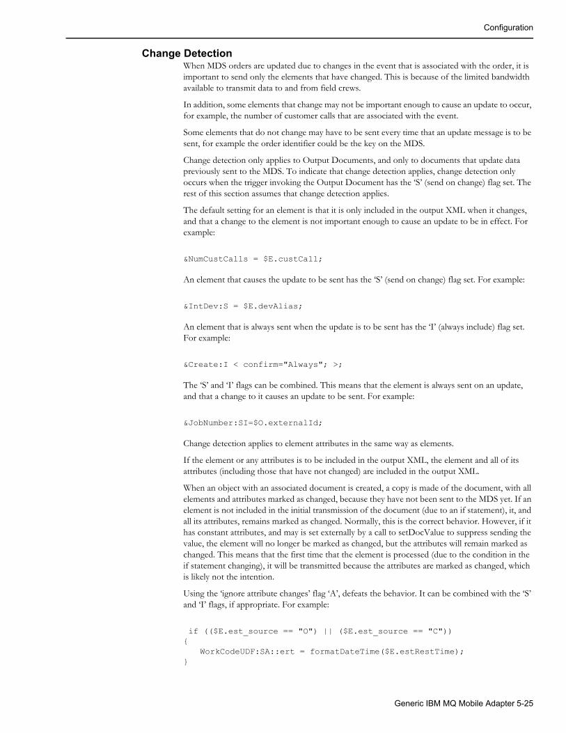
Configuration
Change DetectionWhen MDS orders are updated due to changes in the event that is associated with the order, it is important to send only the elements that have changed. This is because of the limited bandwidth available to transmit data to and from field crews.
In addition, some elements that change may not be important enough to cause an update to occur, for example, the number of customer calls that are associated with the event.
Some elements that do not change may have to be sent every time that an update message is to be sent, for example the order identifier could be the key on the MDS.
Change detection only applies to Output Documents, and only to documents that update data previously sent to the MDS. To indicate that change detection applies, change detection only occurs when the trigger invoking the Output Document has the ‘S’ (send on change) flag set. The rest of this section assumes that change detection applies.
The default setting for an element is that it is only included in the output XML when it changes, and that a change to the element is not important enough to cause an update to be in effect. For example:
&NumCustCalls = $E.custCall;
An element that causes the update to be sent has the ‘S’ (send on change) flag set. For example:
&IntDev:S = $E.devAlias;
An element that is always sent when the update is to be sent has the ‘I’ (always include) flag set. For example:
&Create:I < confirm="Always"; >;
The ‘S’ and ‘I’ flags can be combined. This means that the element is always sent on an update, and that a change to it causes an update to be sent. For example:
&JobNumber:SI=$O.externalId;
Change detection applies to element attributes in the same way as elements.
If the element or any attributes is to be included in the output XML, the element and all of its attributes (including those that have not changed) are included in the output XML.
When an object with an associated document is created, a copy is made of the document, with all elements and attributes marked as changed, because they have not been sent to the MDS yet. If an element is not included in the initial transmission of the document (due to an if statement), it, and all its attributes, remains marked as changed. Normally, this is the correct behavior. However, if it has constant attributes, and may is set externally by a call to setDocValue to suppress sending the value, the element will no longer be marked as changed, but the attributes will remain marked as changed. This means that the first time that the element is processed (due to the condition in the if statement changing), it will be transmitted because the attributes are marked as changed, which is likely not the intention.
Using the ‘ignore attribute changes’ flag ‘A’, defeats the behavior. It can be combined with the ‘S’ and ‘I’ flags, if appropriate. For example:
if (($E.est_source == "O") || ($E.est_source == "C")){
WorkCodeUDF:SA::ert = formatDateTime($E.estRestTime);}
Generic IBM MQ Mobile Adapter 5-25
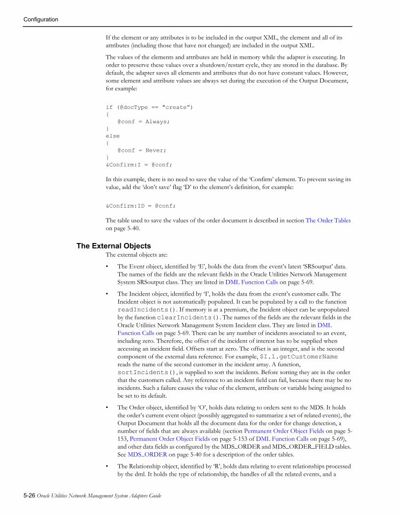
Configuration
If the element or any attributes is to be included in the output XML, the element and all of its attributes (including those that have not changed) are included in the output XML.
The values of the elements and attributes are held in memory while the adapter is executing. In order to preserve these values over a shutdown/restart cycle, they are stored in the database. By default, the adapter saves all elements and attributes that do not have constant values. However, some element and attribute values are always set during the execution of the Output Document, for example:
if (@docType == "create”){
@conf = Always;}else{
@conf = Never;}&Confirm:I = @conf;
In this example, there is no need to save the value of the ‘Confirm’ element. To prevent saving its value, add the ‘don’t save’ flag ‘D’ to the element’s definition, for example:
&Confirm:ID = @conf;
The table used to save the values of the order document is described in section The Order Tables on page 5-40.
The External ObjectsThe external objects are:
• The Event object, identified by ‘E’, holds the data from the event’s latest ‘SRSoutput’ data. The names of the fields are the relevant fields in the Oracle Utilities Network Management System SRSoutput class. They are listed in DML Function Calls on page 5-69.
• The Incident object, identified by ‘I’, holds the data from the event’s customer calls. The Incident object is not automatically populated. It can be populated by a call to the function readIncidents(). If memory is at a premium, the Incident object can be unpopulated by the function clearIncidents(). The names of the fields are the relevant fields in the Oracle Utilities Network Management System Incident class. They are listed in DML Function Calls on page 5-69. There can be any number of incidents associated to an event, including zero. Therefore, the offset of the incident of interest has to be supplied when accessing an incident field. Offsets start at zero. The offset is an integer, and is the second component of the external data reference. For example, $I.1.getCustomerName reads the name of the second customer in the incident array. A function, sortIncidents(), is supplied to sort the incidents. Before sorting they are in the order that the customers called. Any reference to an incident field can fail, because there may be no incidents. Such a failure causes the value of the element, attribute or variable being assigned to be set to its default.
• The Order object, identified by ‘O’, holds data relating to orders sent to the MDS. It holds the order’s current event object (possibly aggregated to summarize a set of related events), the Output Document that holds all the document data for the order for change detection, a number of fields that are always available (section Permanent Order Object Fields on page 5-153, Permanent Order Object Fields on page 5-153 of DML Function Calls on page 5-69), and other data fields as configured by the MDS_ORDER and MDS_ORDER_FIELD tables. See MDS_ORDER on page 5-40 for a description of the order tables.
• The Relationship object, identified by ‘R’, holds data relating to event relationships processed by the dml. It holds the type of relationship, the handles of all the related events, and a
5-26 Oracle Utilities Network Management System Adapters Guide

Configuration
number of fields that are always available (see section Permanent Relationship Object Fields on page 5-153, Permanent Relationship Object Fields on page 5-153 of DML Function Calls on page 5-69).
• The Global Data object, identified by ‘G’, which holds named values for use by any of the documents. A field is created by assigning values to the field, e.g., $G.QueueManager = OPS;. If a field that has not been created is read, the field is created with a value of "", the empty string, and an warning is output to the log. The global data object usually holds configuration data, and the fields are set in a Configuration Document.
• The Trigger Parameter object, identified by ‘T’, which holds the parameters sent to Output Documents when they are triggered from another document using the function ‘triggerOutputDoc’. The first parameter to ‘triggerOutputDoc’ specifies the Output Document to trigger, the second parameter specifies the trigger to pull, and the rest of the parameters values are available to the Output Document as fields ‘1’, ‘2’ … up to the number of parameters supplied, less two (the document and trigger names). For example, @param1 = $T.1; sets the variable ‘param1’ to the value of the first parameter.
Input Element ArraysThe declaration of input elements discussed in section Input Elements and Attributes on page 5-19. can only handle elements whose tags are unique within the bounding parent element (which may be the root element). If such an element appears in the input XML, its value (or those of its own sub-elements) will override the values previously read. Input element arrays solve this problem.
Generally there are two situations that repeated elements are required:
• When the elements contain the same type of data and each should be processed in a similar fashion. For example, a crew logs on when the MDS had previously assigned multiple orders to the crew. Each of these assignments should be made to the crew on Oracle Utilities Network Management System.
• When the elements contain different types of data, and the individual elements are identified by the value of a particular attribute, in effect giving the element a compound tag.
Using an element array with an unspecified index solves the first situation. For example:
&CrewAssignments{&CrewAssignment[]{&OrderId;&AssignmentStatus;}}
This allows any number of elements with the tag ‘CrewAssignment’ to be processed. This can be achieved using the ‘for’ statement described below.
Using an element array with a specified index attribute solves the second situation. For example:
&UDFS{&UDF[idx];}
@etr = &UDFS/UDF[et];@troubleType = &UDFS/UDF[tt];
which assigns the ‘UDF’ element whose ‘idx’ attribute is ‘et’ to the variable ‘etr’ and the ‘UDF’ element whose ‘idx’ attribute is ‘tt’ to the variable ‘troubleType’.
Generic IBM MQ Mobile Adapter 5-27

Configuration
Array elements can be given alternate names in the same way as normal input elements, but they cannot be given flags and defaults, as they have no meaning. Individual array indices can be required to be present, using a required index specification. For example:
&UDFS{&UDF[idx] R(et, tt);}
@etr = &UDFS/UDF[et];@troubleType = &UDFS/UDF[tt];
Prevents the processing of the input XML when the input XML does not contain a ‘UDF’ element with an ‘idx’ attribute of ‘et’ and contain a ‘UDF’ element with an ‘idx’ attribute of ‘tt’. The required index specification consists of an ‘R’ followed by a comma separated list of attribute values in parentheses ‘(‘ ‘)’.
While sub-elements to array elements can be given names, their usage differs from normal sub-elements because the appropriate index must be specified. This is done using a format similar to the long form of referencing tags, using forward slashes ‘/’. For example:
&ancestor{
&grandparent[idx]{
&parent{&child;}
}}@son = &ancestor/grandparent[smith]/parent/child;
uses the full long form.
&ancestor{
&grandparent[idx]:::granny{
&parent{&child;}
}}@son = &granny[smith]/parent/child;
uses a name for the array element.
&ancestor{
&grandparent[idx]:::granny{
&parent{&child:::son;}
}}@son = granny[smith]/son;uses a name for both the array element and its sub-element.
5-28 Oracle Utilities Network Management System Adapters Guide

Configuration
For StatementThe for statement, or for loop, is used to iterate through the contents of an array element.
The array element can either have a specified index attribute or an unspecified index. The usage is similar.
For example:
&CrewId:R;
&CrewAssignments{&CrewAssignment[]:::asn{&OrderId;&AssignmentStatus;}}if (!findCrewById(&CrewId)){
stop;}
for (&asn[], @i){
if (isSet(&asn[@i]/OrderId) && isSet(&asn[@i]/AssignmentStatus) && findOrder(externalId, (&asn[@i]/OrderId))
{if (&asn[@i]/AssignmentStatus == ASN)
{assignCrew();
}elseif (&asn[@i]/AssignmentStatus == DSP){dispatchCrew();
}}
}
The for statement executes all the statements between the matching brackets ‘{‘ and ‘}’, for each of the elements in the tag array (‘&asn[]’ in this case), in the order that they appeared in the input XML. During execution of the statements the ‘for’ variable (‘@i’ in this case) is set to the elements index in the tag array. As this array did not have an index attribute specified, the variable has a numeric value, starting at zero, and is incremented by one between loop executions. If the XML does not contain the element, the loop is never executed.
If, instead, the array element had an index attribute, for example:
&CrewAssignments{&CrewAssignment[idx]:::asn{&OrderId;&AssignmentStatus;}}
the loop variable would contain the values for the ‘idx’ attribute included in the input XML. Note, however, that if the XML contained any ‘CrewAssignment’ elements, without an ‘idx’ attribute, these elements would be ignored, and therefore not available for processing.
Generic IBM MQ Mobile Adapter 5-29

Configuration
Queue SpecificationThe queue specification is used to specify the queue that XML from Output Documents are sent to, and the queue that input XML is received on to be processed by Input Documents. The queue specification appears in the header portion of the document. For example:
queue = NMS.TO.MDS.REQUEST;
Which sets the queue name to a constant. Commonly, the queue is set to the value of a field in the global object to facilitate the configuration of the queue names.
Output Documents can change the queue name by accessing the queue variable in the body of the document. For example:
If (@use_alternate_queue){
@queue = $G.alternateQueue;}
Association of an Output Document to the Order ObjectThe order document must have an associated Output Document that generates the Order creation (usually) and update (always) XML. It is used to cache all the element data that is used for change detection. This association is achieved using the associate specification in the document header which takes the form:
associate = O;
where the ‘associate’ is the associate keyword and the ‘O’ identifies the Order Object.
TriggersTriggers specify when Output Documents are activated to generate XML to be sent to the MDS. For example:
trigCreateOrder < SRSoutput; > = ($E.status == "ACK") && !findOrder(event, $E.outageHdl);
might be used to trigger the creation of an order.
The ‘trigCreateOrder’ is the trigger’s name. The value of a trigger is available to the body of the document in a variable with this name.
The angle brackets, ‘<’ and ‘>’, contain the trigger specification(s), which define the circumstances under which the trigger is to be tested. In this case the arrival of an asynchronous ‘SRSoutput’ message.
After the assignment is the expression which determines when the trigger is to be fired. The expression is evaluated and if it is true, i.e. not the empty string, the trigger is fired. The result of this evaluation is then assigned to the trigger variable. In the example, the trigger will fire if the event is in the acknowledged state and no order has been created for the event.
If an expression is not supplied, the trigger always fires when the trigger specification is satisfied. In this case, its value is set to ‘Y’.
5-30 Oracle Utilities Network Management System Adapters Guide

Configuration
Triggers can also have the ‘send on change’ ‘S’ flag set. If not set, all elements in the document are sent in the resulting XML. If set, only those elements that have changed are set. For example:
trigUpdateOrder:S < SRSoutput; > = (!isIn($E.status, "UNA", "CNL") && findOrder(event, $E.outageHdl);
There can be multiple triggers, only one of which is fired. The triggers are evaluated in order of their definitions and the first to fire takes effect. The unfired triggers all have a value of false.
There are a number of types of trigger specifications. In some cases they need values. They are:
• The reception of a SRSoutput message. The trigger specification is ‘SRSoutput’, which has no value. Examples of the SRSoutput trigger are shown above.
• When an event is deleted. This occurs when outages are merged, and when a previously processed event is not returned by JMService at start up. The trigger specification is ‘EventNonexistent’, which has no value. Commonly, this triggers the same Output Document that handles event cancellation. The event is supplied in trigger parameter 1. An example of an event non-existent trigger is:
triggerEventNonexistent<EventNonexistent;> = findOrder(order, $T.1) && $O.externalId;
• Periodically. The trigger specification is ‘Periodic’, which needs a value that is the period at which to fire the trigger, in seconds. An example of a periodic trigger that fires once a minute is:
trig1min< Periodic=60; >;
• By request in another document, using the ‘triggerOutputDoc’ function. The trigger specification is ‘OnRequest’, which needs a value that is the number of trigger parameters that need to be passed by the requesting document. An example of a request trigger with two parameters is:
trigOnRequest<OnRequest=2;> = findOrder(event, $T.1) && isIn($E.status, "UNA", "CNL") && $O.externalId;
• Creation of, changes to the number of events in, and deletion of an event relationship processed by dml. The trigger specification is ‘RelationChanged’, which as no value. The Output Document is activated once for each event in the relationship. The event is supplied in trigger parameter 1. An example of an relationship change trigger is:
trigRelationChanged< RelationChanged; >= findOrder(event, $T.1) && isIn($E.status, "UNA", "CNL");
• Deletion of an event relation processed by dml. The trigger specification is ‘RelationDeleted’, which as no value. The Output Document is activated once for the relationship. The relation is supplied in trigger parameter 1. An example of an relationship deletion trigger is:
trigRelationDeleted< RelationDeleted; >= findOrder(RELATED_OUTAGE, relation, $T.1) && $R.externalId;
Generic IBM MQ Mobile Adapter 5-31

Configuration
• A change to the number of events in an event relation that is aggregated by the adapter. The trigger specification is ‘AggregateChanged’, which has no value. The Output Document is activated once for the order in which the events are aggregated. The order is supplied in trigger parameter 1. An example of an aggregate change trigger is:
trigAggregateChanged< AggregateChanged; >= findOrder(order, $T.1) && $O.externalId;
This trigger is often used to ensure that all events in the relation have data updates sent by the MDS before new events are added to the relationship, for example the estimated time to restore.
• An SRSoutput message arrives indicating number of events are merged. The trigger specification is ‘EventMerged’. Its value specifies the name of an Output Document, known as the Merge Priority Document, which is used to generate the priority of all of the orders associated with the events involved in the merge, if any. The Merge Priority Document must have a request trigger named ‘call’. The Output Document that contains the event merged trigger is known as the Merge Document. There can be zero or one Merge Document in all the dml files processed by the adapter. If no Merge Document is supplied, the SRSoutput message is processed via SRSoutput triggers, and the merged events are processed via event non-existent triggers. If a Merge Document is supplied, the adapter processes the SRSoutput message as follows:
1. For each of the events involved in the merge, including the surviving event, the adapter determines whether the event is associated with an order. If so it’s order becomes eligible to be the surviving order, except for a non-surviving event’s order is in an aggregate relationship. If there are no eligible orders, the SRSoutput message is processed via SRSoutput triggers, and the merged events are processed via event non-existent triggers. Neither the Merge Document nor the Merge Priority Document is processed.
2. When there are multiple eligible orders, the adapter must choose which one will become the survivor. The Merge Priority Document provides a priority value to allow this choice to be made. The adapter processes the Merge Priority Document via the ‘call’ trigger. The Merge Priority Document has its order and event objects set. Note that if the event is the surviving event, the previous version of the event object is set. This allows the event object’s fields before the merge to be used to determine the priority.
3. The Merge Priority Document returns the priority in the trigger argument object. The priority consists of a priority sort definition and one or more priority values. The priority sort definition is returned in the ‘0’ (the character zero) field of the trigger argument object ($T.0). If this value is the empty string, the order is no longer eligible to survive. If not empty, it defines the number and sort order of the priority values. The priority values are returned the ‘1’, ‘2’, … fields ($T.1, $T.2, …), up to the number of values. The number of characters in the priority sort definition determines the number of values expected by the adapter. Each character determines the sort order for the corresponding value, ‘A’ or ‘a’ for ascending and ‘B’ or ‘b’ for descending, the first character applies to $T.1, the second to $T.2, etc.
4. If there are multiple orders eligible, the one with the highest priority becomes the survivor. Each priority value is sorted alphabetically in the order specified by its character in the priority sort definition. The first value ($T.1) is examined first. If one order ranks higher that all the other, it is chosen. Otherwise, any order with a lower priority is discarded. Then the other values are examined in turn, until an order is chosen. If all the priorities are the same, the order associated with the surviving event, if any, survives. If the surviving event has no order, the order associated with the oldest event survives. For example, the following dml fragment illustrates how to choose the order with the most advanced crew assignment/dispatch status, and if they are equal the order with the oldest event.
5-32 Oracle Utilities Network Management System Adapters Guide

Configuration
# two priority values, the first descending, the second ascending $T.0 = DA;
# orderCrewStatus() returns ’A’ for Assigned, ‘D’ for dispatched, ‘O’ for on site, nothing for none
@ocr = orderCrewStatus();if (@ocr){$T.1 = @ocr;}else{# ‘a’ precedes all of the valid values$T.1 = a;}
# formatDateTime() returns the date and time in the format# YYYY-MM-DDTHH:MM:SS$T.2 = formatDateTime($E.outageTime);
5. The Merge Priority Document can populate other fields in the trigger argument object, to be used by the Merge Document when the order being processed becomes the surviving order. Note that the Merge Priority Document is processed even if there is only one eligible order so that these fields, if any, can be passed to the Merge Document.
6. If the surviving order is not associated with the surviving event, the surviving order is re-associated to the surviving event. The order that was associated with the surviving event is re-associated to the surviving order’s old event, so that it can be processed via an event non-existent trigger, to allow normal order clean up.
7. The adapter processes the Merge Document with the surviving order object and surviving event object set to the new version of the event, and the trigger argument object fields set by the Merge Priority Document when processing the surviving order.
8. Finally, the SRSoutput message is processed via SRSoutput triggers, and the merged events are processed via event non-existent triggers.
An example of an event merged trigger is:
TrigEventMerged <EventMerged="OrderMergePriority";>;
For this to be valid, there must be an Output Document named ‘OrderMergePriority’, with a request trigger named ‘call’.
The Root ElementThe root element is the element that contains all of the other elements in an XML document. The root element in dml serves a different purpose depending on whether it is part of an Output or Input Document.
In an Output Document, it is used to generate the root element in the XML to be sent. In an Input Document it is used to select the Input Document or Documents that the input XML can be processed by, similar to a trigger for an Output Document. An example of a root element follows:
Generic IBM MQ Mobile Adapter 5-33

Configuration
&RootElement <environment = $G.environment; revision = "1.0.0";> = CreateJob;
The root element has the same format for both Input and Output Documents.
The root element differs from other elements in that the element’s tag is defined by the value of the element, ‘CreateJob’ in this example. The pseudo-tag ‘RootElement’ keyword identifies it to be the root element.
In an Output Document, the example would generate the following start element tag:
<CreateJob environment="Test" revision="1.0.0">
assuming that the global field ‘environment’ held the value ‘Test’.
To select an Input Document, the input XML’s root element must have the same tag, and all the attributes in the root element specification must be present and have exactly the same contents. Extra attributes in the XML’s root element are ignored.
An Input Document with the same root element definition example above would be selected by the root element in the example above.
The root element is defined in different areas, depending on the type of document.
In an Output Document the root element is in the body of the document, because it’s tag may have to be determined during document processing. It is the only element in an Output Document that is an exception to the rule that states that elements are generated in the order that they appear in the Output Document.
In an Input Document the root element is the header of the document because it is used before any processing is done in the document.
The Base PathThe base path only applies to Input Documents, and is not necessary, but can make Input Documents more compact. Consider the following XML:
<ConfirmJob> <ApplicationArea> </ApplicationArea> <DataArea> <Job> <OriginalApplicationArea> <BODId>OrigBODId</BODId> </OriginalApplicationArea> <CreateSuccess> <JobNumber>1234567890</JobNumber> </CreateSuccess> </Job> </DataArea></ConfirmJob>
The XML could contain many other elements, but the ‘BODId’ and ‘JobNumber’ are the only elements to be processed. The elements in the Input Document would be:
&DataArea{
&Job{
&OriginalApplicationArea{&BODId;
5-34 Oracle Utilities Network Management System Adapters Guide

Configuration
}&CreateSuccess{&JobNumber;}
}}
Note that ‘BODId’ and ‘JobNumber’ have a common grandparent ‘Job’. By setting the base element to the grandparent by adding:
BasePath = DataArea/Job;
to the document’s header, the elements would become:
&OriginalApplicationArea{
&BODId;}&CreateSuccess{
&JobNumber;}
Stop Statement The Stop statement causes the processing of the current document to stop. It takes the form:
stop;
It is usually contained in an ‘if’ statement. Any statements with side effects, for example a SQL Insert, processed before the ‘stop’ do take effect.
A stop statement prevents an Output Document’s XML from being sent.
A stop statement in a Configuration Document, described below, causes initialization to fail.
Include StatementSometimes it’s useful to have the same set of statements in two different places in a dml file. For example all Output Documents may need the same header, or application area. This can be achieved by placing the repeated statements in another file and then including the file more than once in another file. The following is an ‘include’ statement:
include ohdr.dml
This ‘include’ statement in effect replaces the text ‘include ohdr.dml’ with the contents of the file ‘ohdr.dml’. Files being included can also include other files, but the nesting level is limited to 10 deep so that infinite recursion can be prevented.
Configuration DocumentsConfiguration Documents are used to set configuration data and load configuration tables from the database at initialization time. They are similar to Input Documents, but have no elements.
They are processed at initialization time, and are then discarded. Any errors encountered when processing a Configuration Document should be made fatal by executing a stop statement, causing initialization to fail.
Common uses are to set fields in the global data object, including configuration fields, and to load mapping tables, used by the ‘mapTableStr’ and ‘mapTableCode’ functions described in DML Function Calls on page 5-69. For example:
Generic IBM MQ Mobile Adapter 5-35
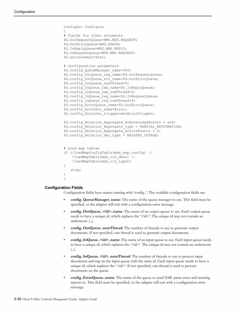
Configuration
ConfigDoc Configure{# fields for other documents$G.OutRequestQueue=NMS.MDS.REQUEST;$G.OutErrorQueue=NMS.ERROR;$G.InReplyQueue=MDS.NMS.REPLY;$G.InRequestQueue=MDS.NMS.REQUEST;$G.environment=Test;
# configuration parameters$G.config_QueueManager_name=OPS;$G.config_OutQueue_req_name=$G.OutRequestQueue;$G.config_OutQueue_err_name=$G.OutErrorQueue;$G.config_OutQueue_numThread=5;$G.config_InQueue_rep_name=$G_InReplyQueue;$G.config_InQueue_rep_numThread=2;$G.config_InQueue_req_name=$G.InRequestQueue;$G.config_InQueue_req_numThread=4;$G.config_ErrorQueue_name=$G.OutErrorQueue;$G.config_ErrorDoc_name=Error;$G.config_ErrorDoc_trigger=xmlErrorTrigger;
$G.config_Relation_Aggregate_AcknowledgeEvents = ack;$G.config_Relation_Aggregate_type = PARTIAL_RESTORATION;$G.config_Relation_Aggregate_ActiveEvents = Y;$G.config_Relation_dml_type = RELATED_OUTAGE;
# Load map tablesif (!loadMapConfigTable(mds_map_config) || !loadMapTable(mds_cls_desc) || !loadMapTable(mds_cls_type)){
stop;}}
Configuration FieldsConfiguration fields have names starting with ‘config_’. The available configuration fields are:
• config_QueueManager_name: The name of the queue manager to use. This field must be specified, or the adapter will exit with a configuration error message.
• config_OutQueue_<id>_name: The name of an output queue to use. Each output queue needs to have a unique id, which replaces the ‘<id>’. The unique id may not contain an underscore (_).
• config_OutQueue_numThread: The number of threads to use to generate output documents. If not specified, one thread is used to generate output documents.
• config_InQueue_<id>_name: The name of an input queue to use. Each input queue needs to have a unique id, which replaces the ‘<id>’. The unique id may not contain an underscore (_).
• config_InQueue_<id>_numThread: The number of threads to use to process input documents arriving on the input queue with the same id. Each input queue needs to have a unique id, which replaces the ‘<id>’. If not specified, one thread is used to process documents on the queue.
• config_ErrorQueue_name: The name of the queue to send XML parse error and warning reports to. This field must be specified, or the adapter will exit with a configuration error message.
5-36 Oracle Utilities Network Management System Adapters Guide

Configuration
• config_ErrorDoc_name: Specify an output document to process error reports. If specified, the config_ErrorDoc_trigger field must be specified. If not specified, the standard XML error document, as specified in the MQ/XML adapter documentation, is used.
• config_ErrorDoc_trigger: The trigger to pull in the error document when there is an error or warning to report. Ignored is no error document is specified. If the specified trigger does not exist in the error document, the adapter exits with a configuration error message. The adapter supplies three trigger arguments to the error document. Argument one is the error or warning message description, argument two is the priority level, one of ‘Warning’, ‘Error’, and ‘Fatal Error’, and argument three is the offending XML document.
• config_Relation_Aggregate_type: A comma separated list of relationship types to aggregate. The relationship types are: NESTED_OUTAGE, MOMENTARY_OUTAGE, PARTIAL_RESTORATION, and RELATED_OUTAGE. If a pseudo relationship of a type that is aggregated by the adapter is created using createPseudoRelation(), the pseudo relation is aggregated. If a relationship type is configured for both aggregation and dml processing, the adapter exits with a configuration error.
• config_Relation_Aggregate_AcknowledgeEvents: Acknowledge all unacknowledged events in aggregate relations. The value of this field is used in a call to JMS::requestRowAction() as the button name. This field should be set if pseudo aggregate relations are created on events that may not be acknowledged.
• config_Relation_Aggregate_ActiveEvents: If the field is not the empty string "", sum count data for all active events in an aggregated relation. The count data event fields are: customersOut, crit_k, crit_c, and crit_d.
• config_Relation_dml_type: A comma separated list of relationship types to be processed by the dml, using the relationship object. The relationship types are: NESTED_OUTAGE, MOMENTARY_OUTAGE, PARTIAL_RESTORATION, and RELATED_OUTAGE. If a pseudo relationship of a type that is processed by the dml is created using createPseudoRelation(), the pseudo relation is processed by the dml. If a relationship type is configured for both aggregation and dml processing, the adapter exits with a configuration error.
• config_Relation_dml_AcknowledgeEvents: Acknowledge all unacknowledged events in dml processed relations. The value of this field is used in a call to JMS::requestRowAction() as the button name.
• config_MaxBackoutCount: The adapter uses the MQSeries syncpoint facilities to preserve input messages when there is a failure. Using the MQSeries syncpoint facilities introduces the possibility that a 'poison' message will be sent by the MDS. A 'poison' message is one that can never be successfully processed, for example because an Oracle Utilities Network Management System table has a constraint that the contents of the message violate. If the 'poison' message is never discarded, MDS will continually try to process the message, fail, and then restart. This parameter sets a limit on the number of restarts that MDS will perform before discarding a message. The default value is five. A value of zero disables this feature. If a message is discarded, the error is logged to the log file, including the offending XML, and if the error document is configured, and an error report is sent to the error queue.
• config_Event_QueueDelay: When event data is received in an SRSoutput message, from JMService, they are held for this period before they are queued for processing. If another message for the same event is received before the delay has expired, the older message is discarded, and the new message is held for the delay period. This avoids unnecessary processing and message transmission when event data is changing rapidly. Setting this delay too short can cause extra messages, while setting it too long can cause poor response. The value is in seconds. The default value is four seconds. A value of zero disables this feature.
• config_Event_ReprocessPeriod: In certain circumstances, for example when more that one event is grouped, the adapter needs to request an event’s status from JMService. The adapter periodically requests these events’ statuses in a single request, reducing the burden on
Generic IBM MQ Mobile Adapter 5-37

Configuration
JMService. In addition, if an SRSoutput message for one of these events arrives before it is time to do the request, the request does not have to be made. Setting this period too short can cause extra messages, while setting it too long can cause poor response. The value is in seconds. The default value is six seconds. The minimum value is two seconds. It must be at least 2 seconds longer than config_Event_QueueDelay.
• config_Crew_AssignmentCheckPeriod: When the assignment of crews to events is the responsibility of the adapter, as a proxy for the MDS, Oracle Utilities Network Management System can be configured to reduce the possibility of an operator inadvertently assigning a crew to an event. However, it must be possible to assign crews if Oracle Utilities Network Management System cannot communicate with the MDS, hence mistakes can happen. The adapter periodically checks all crew assignments. A sub-set of crew assignments is checked at the end of each period, the events in ten orders, and ten crews for events not in an order being checked each time. Setting the period too short causes unneeded processing, setting it too long delays such mistakes being repaired. The value is in seconds. The default value is six seconds. A value of zero disables this feature.
• config_Crew_MoveAssignmentCheckDelay: When crew assignments are being checked, allowing the checking to occur during event grouping can, in some configurations, cause unnecessary message traffic between the adapter and JMService. To prevent this, when a grouping happens, crew assignment checking is delayed. The value is in seconds. The default value is two seconds. A value of zero disables this feature.
• config_Relation_CheckPeriod: When event relationships are processed by the adapter, the adapter loads the relationship database table each time a relationship is created, changed or deleted. In addition, the adapter checks for changes to the table at this period. The value is in seconds. The default value is 30 seconds. A value of zero disables this feature.
• config_IgnoreCondStatus: In most implementations of the adapter, additional alarms in the Oracle Utilities Network Management System Work Agenda should not be processed. The value of this configuration parameter is a list of condition statuses, separated by commas (,), that are to be ignored by the adapter. To ignore additional alarms (often NFY events) set this value to 12.
• config_CompleteStatus: In certain situations the adapter need to be able to determine if an event is complete, for example to prevent the assignment of a crew to a completed event, which is illegal. This can only be determined by examining the status string for the event, which is configurable in Oracle Utilities Network Management System. The value of this configuration parameter is a list of statuses, separated by commas (,), that indicate that an event is complete. The default value of this parameter is CMP, CNL.
• config_EventUpdateTimeout: When device outages are confirmed and restored (using confirmDeviceOutage() and restoreOutage()), the new state of the event(s) needs to be read from JMService. Because device operations are initiated by a message to DDService, which sends a notification to MTService to update the model, which subsequently notifies JMService of the model change, the new state cannot be read immediately, because JMService may not have received the notification. To avoid this, the adapter waits for an SRSoutput message updating the event before reading the new state. To prevent the adapter from hanging if an event update does not occur, a timeout is used to interrupt the wait. This value is the timeout in seconds. The default value is 20 seconds. The minimum is two seconds.
• config_MaxThreadBusyUntilFatalError: The adapter monitors the input and output threads to detect Mutex deadlocks, which would cause the adapter to hang. This value is the maximum number of seconds that a thread can be responding to a single trigger or input XML document. The default value is 300 seconds (5 minutes). The minimum is 60 seconds.
• config_StopServiceOnHighLevelStop: The adapter runs as a Windows Service, and it usually set to restart after a period after it fails. (This period is often the minimum one minute). If the adapter tells Windows that it has stopped normally, using a Service Stop message, just before exiting Windows does not try to restart the adapter. If the adapter does not send a Service Stop message, Windows will restart the adapter. When the adapter exits
5-38 Oracle Utilities Network Management System Adapters Guide

Configuration
due to Stop request from the Service Property dialog, it sends Windows a Service Stop message, because the user is intending that the adapter stops and does not restart. When the adapter exits abnormally, it does not send a Service Stop message so that Windows will restart the adapter. However, when the adapter is sent a high-level stop message from Oracle Utilities Network Management System using the Action command, the user may or may not want the adapter to restart. This value determines whether the adapter sends a Service Stop message under these circumstances. A value of ‘Y’ causes the adapter to send a Service Stop message, while a value of ‘N’ prevents the adapter from sending a Service Stop message. The default value is ‘N’.
• config_AllowCloseOutEventCancel: When this parameter is set to 'Y,' the DML function closeOutEvent will cancel the event instead of completing it, if the appliedRule value OUTAGE_PND_COMPLETE (26) is passed to the function. When this parameter is set to 'N,' the DML function closeOutEvent will not cancel events. The default value is 'Y'.
• config_IgnoreStormmanUpdates: When this parameter is to set to 'Y' (default), the adapter will not process TRBL_ERT_UPDATE messages generated when Storm Management recalculates ERTs. When this parameter is to set to 'N' the adapter will process such messages.
• config_AllowManualEntryForSCADA: When this parameter is to set to 'Y,' the adapter will perform manual entry in order to operate SCADA device in the NMS model. When this parameter is to set to 'N' (default), the adapter will not be able to operate SCADA devices.
• config_Username: Username under which the adapter will perform crew-related API calls into NMS. Default value is 'MDS'.
• config_UseGlobalUsernameForCrewOps: If set to 'Y,' then the value specified by the '$G.config_Username' will be used as the username under which the adapter will perform crew-related API calls to NMS. This is the default setting.
If set to 'N,' then the adapter will use the username provided in the DML function call. If a particular crew-related DML function does not accept username parameter or if the supplied parameter is empty the '$G.config_Username' value will be used.
• config_BlockingMqGetEnable: (boolean) If true, the blocking get() behavior will be enabled. Default is false.
• config_BlockingMqGetWaitInterval: (integer) The number of milliseconds that the adapter will wait for a message to appear on the queue before the MQGET call completes with the MQRC_NO_MSG_AVAILABLE reason code. This option only takes effect if config_BlockingMqGetEnable is “true”. Default is 2000 ms.
Pseudo RelationshipsPseudo relationships can be created by the dml so that all the events on a single device can be processed in the same way as an Oracle Utilities Network Management System created event relationship. The processing of these relationships is configured in a configuration document.
For example, a probable device outage is created from multiple customer calls grouping to the common transformer, but the crew discovers that there are multiple service problems only affecting some of the customers (perhaps a tree limb took down two service wires). The crew will fix all of the problems, so they do not need multiple MDS orders. When the individual service status is set for the affected customers, all the events generated will be treated in the same way as a partial restoration. (This example assumes that partial restorations are aggregated, and the dml creates a pseudo partial relationship when this situation arises.)
When all of the events in a pseudo relation are completed, the relation itself is automatically completed.
Generic IBM MQ Mobile Adapter 5-39

Configuration
Configuration TablesThe following tables are used in conjunction with the dml files to configure the MDS adapter. They are loaded at startup, or, in some cases, when a dml statement needs them.
The Order TablesThe order tables save order data and configure the fields that are available to the dml in the external Order object, identified by ‘O’ in the dml.
MDS_ORDERThe MDS_ORDER table is used to save order data so that the adapter can continue to process orders over a adapter shutdown restart cycle. While not strictly a configuration table, it is described here to clarify the use of other configuration tables. The table has a fixed set of columns that are always in the table, and columns to hold Order object field values, element values and attribute values. The fixed set of columns is:
The ‘h_cls’ and ‘h_idx’ columns make up the order handle, which identifies the order internally and are the key columns of the table. The order handle is available to the dml with a field name of ‘order’. The ‘event_cls’ and ‘event_idx’ columns make up the handle of the key event for the order. If the event is not aggregated, this is the single event associated with the order. If the event is aggregated, this is the key event of the relationship that makes up the aggregate. The event handle is available to the dml with a field name of ‘event’. The ‘active’ flag indicates whether the order is active, i.e. it has been created, but has neither been completed or cancelled. ‘when_created’ holds the time and date the order was created. ‘when_completed’ holds the time and date the order was completed or cancelled. comp_reason hold the text explaining why the order was completed or cancelled. This text is supplied by the dml when it completes the order by calling the ‘orderComplete’ function.
The columns that hold the field, element and attribute values can have any name, but they must match the contents of the MDS_ORDER_FIELD table and MDS_ORDER_VALUE table. Both are described below. It is suggested that the columns be named similarly to the name of the entity, allowing for the requirements of column names (case insensitivity, etc.). The column types should be VARCHAR2. The columns should be wide enough to hold the data that will be stored in them. The off-line program that allows dml files to be checked before use can generate suggested contents for the MDS_ORDER, MDS_ORDER_FIELD, and MDS_ORDER_VALUE tables.
Column Type Description
h_cls NUMBER Order class
h_idx NUMBER Order Index
event_cls NUMBER Key event class
event_idx NUMBER Key event index
active_event_cls NUMBER Event class for last active event
active_event_idx NUMBER Event index for last active event
active CHAR(1) Active flag (Y = active, N = inactive)
when_xml_saved DATE When the xml data last sent to the MDS was saved in the database.
when_created DATE When the order was created
when_completed DATE When the order was completed or cancelled
comp_reason VARCHAR2(64) Text explaining why the order was completed or cancelled
5-40 Oracle Utilities Network Management System Adapters Guide
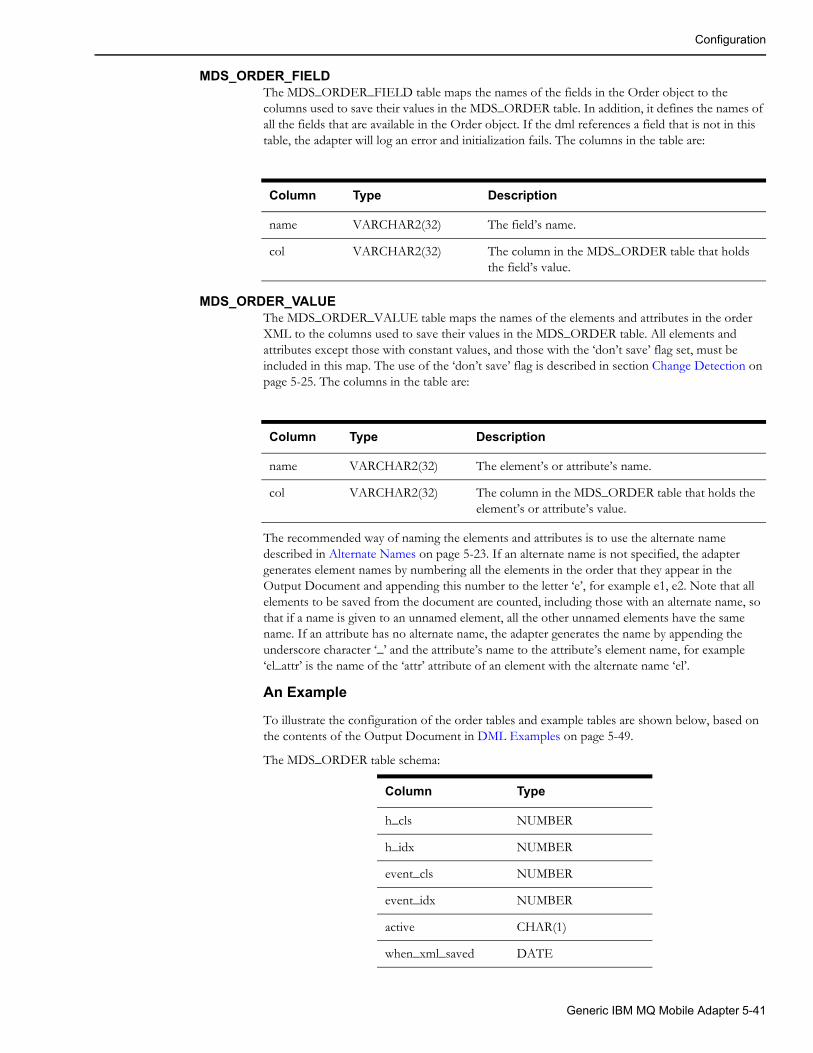
Configuration
MDS_ORDER_FIELDThe MDS_ORDER_FIELD table maps the names of the fields in the Order object to the columns used to save their values in the MDS_ORDER table. In addition, it defines the names of all the fields that are available in the Order object. If the dml references a field that is not in this table, the adapter will log an error and initialization fails. The columns in the table are:
MDS_ORDER_VALUEThe MDS_ORDER_VALUE table maps the names of the elements and attributes in the order XML to the columns used to save their values in the MDS_ORDER table. All elements and attributes except those with constant values, and those with the ‘don’t save’ flag set, must be included in this map. The use of the ‘don’t save’ flag is described in section Change Detection on page 5-25. The columns in the table are:
The recommended way of naming the elements and attributes is to use the alternate name described in Alternate Names on page 5-23. If an alternate name is not specified, the adapter generates element names by numbering all the elements in the order that they appear in the Output Document and appending this number to the letter ‘e’, for example e1, e2. Note that all elements to be saved from the document are counted, including those with an alternate name, so that if a name is given to an unnamed element, all the other unnamed elements have the same name. If an attribute has no alternate name, the adapter generates the name by appending the underscore character ‘_’ and the attribute’s name to the attribute’s element name, for example ‘el_attr’ is the name of the ‘attr’ attribute of an element with the alternate name ‘el’.
An Example
To illustrate the configuration of the order tables and example tables are shown below, based on the contents of the Output Document in DML Examples on page 5-49.
The MDS_ORDER table schema:
Column Type Description
name VARCHAR2(32) The field’s name.
col VARCHAR2(32) The column in the MDS_ORDER table that holds the field’s value.
Column Type Description
name VARCHAR2(32) The element’s or attribute’s name.
col VARCHAR2(32) The column in the MDS_ORDER table that holds the element’s or attribute’s value.
Column Type
h_cls NUMBER
h_idx NUMBER
event_cls NUMBER
event_idx NUMBER
active CHAR(1)
when_xml_saved DATE
Generic IBM MQ Mobile Adapter 5-41
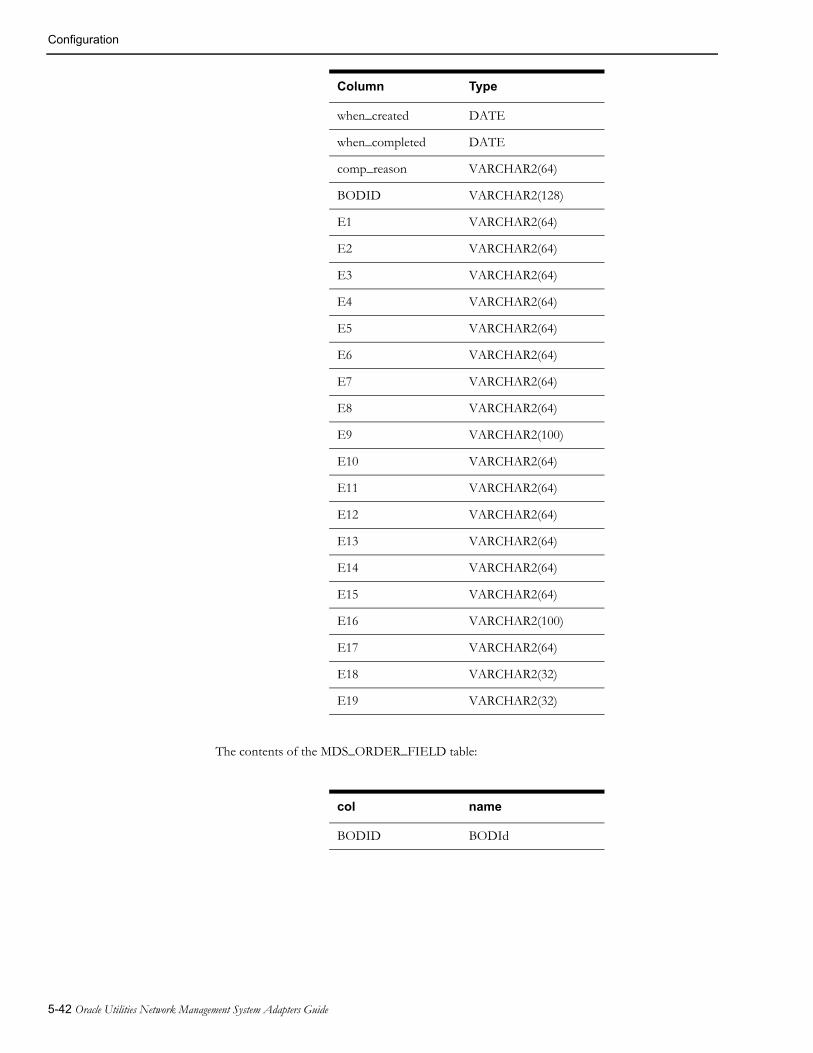
Configuration
The contents of the MDS_ORDER_FIELD table:
when_created DATE
when_completed DATE
comp_reason VARCHAR2(64)
BODID VARCHAR2(128)
E1 VARCHAR2(64)
E2 VARCHAR2(64)
E3 VARCHAR2(64)
E4 VARCHAR2(64)
E5 VARCHAR2(64)
E6 VARCHAR2(64)
E7 VARCHAR2(64)
E8 VARCHAR2(64)
E9 VARCHAR2(100)
E10 VARCHAR2(64)
E11 VARCHAR2(64)
E12 VARCHAR2(64)
E13 VARCHAR2(64)
E14 VARCHAR2(64)
E15 VARCHAR2(64)
E16 VARCHAR2(100)
E17 VARCHAR2(64)
E18 VARCHAR2(32)
E19 VARCHAR2(32)
col name
BODID BODId
Column Type
5-42 Oracle Utilities Network Management System Adapters Guide

Configuration
The contents of the MDS_ORDER_VALUE table (the element tag is not in the table, it is included here to illustrate the numbering of the elements):
col name Element tag
E1 e1 Component
E2 e2 Confirmation
E3 e3 AuthorizationId
E4 e4 CreationDateTime
E5 e5 BODId
E6 e6 ExternalNumber
E7 e7 CreationDateTime
E8 e8 Device
E9 e9 Address
E10 e10 DevPhases
E11 e11 FuseSize
E12 e12 WinterLoad
E13 e13 SummerLoad
E14 e14 NumCustOut
E15 e15 CallerName
E16 e16 CallerAddr
E17 e17 CallerPhone
E18 e18 CallerClues
E19 e19 CallerDevice
Generic IBM MQ Mobile Adapter 5-43

Configuration
The Relationship TablesThe relationship tables save event relationship data and configure the fields that are available to the dml in the external Relationship object, identified by ‘R’ in the dml.
MDS_RELATIONThe MDS_RELATION table is used to save relationship data so that the adapter can continue to process event relationships, and to detect changes in these relationships over a adapter shutdown restart cycle. While not strictly a configuration table, it is described here to clarify the use of other configuration tables. The table has a fixed set of columns that are always in the table, and columns to hold Relationship object field values. The fixed set of columns is:
The columns that hold the field values can have any name, but they must match the contents of the MDS_RELATION_FIELD table, which is described below. It is suggested that the columns be named similarly to the name of the entity, allowing for the requirements of column names (case insensitivity, etc.). The column types should be VARCHAR2. The columns should be wide enough to hold the data that will be stored in them.
The off-line program that allows dml files to be checked before use can generate suggested contents for the MDS_RELATION and MDS_RELATION_FIELD tables.
Column Type Description
h_cls NUMBER Relation class
h_idx NUMBER Relation Index
key_event_cls NUMBER Class of key event
key_event_idx NUMBER Index of key event
pseudo_dev_cls NUMBER Class of pseudo device
pseudo_dev_idx NUMBER Index of pseudo device
type NUMBER The type of relationship one of:NESTED_OUTAGE(1) MOMENTARY_OUTAGE(2) PARTIAL_RESTORATION(4) RELATED_OUTAGE(8) Pseudo relationships have the same number as their type, with the sign bit (bit 31) set.
active CHAR(1) Active flag (Y = active, N = inactive)
when_created DATE When the relationship was created
when_completed DATE When the relationship was completed or cancelled
5-44 Oracle Utilities Network Management System Adapters Guide

Configuration
MDS_RELATION_EVENTThe MDS_RELATION_EVENT table holds the events that are related to the key events in the MDS_RELATION table. It is not a configuration table. Its columns are:
MDS_ RELATION_FIELDThe MDS_RELATION_FIELD table maps the names of the fields in the Relationship object to the columns used to save their values in the MDS_RELATION table. In addition, it defines the names of all the fields that are available in the Relationship object. If the dml references a field that is not in this table, the adapter will log an error and initialization fails. The columns in the table are:
Column Type Description
key_event_cls NUMBER Class of key event
key_event_idx NUMBER Index of key event
event_cls NUMBER Class of related event
event_idx NUMBER Index of related event
active CHAR(1) Active flag (Y = active, N = inactive)
Column Type Description
name VARCHAR2(32) The field’s name.
col VARCHAR2(32) The column in the MDS_RELATION table that holds the field’s value.
Generic IBM MQ Mobile Adapter 5-45

Configuration
The Code Mapping TablesThe code mapping tables and views are used to translate values in Oracle Utilities Network Management System to and from the equivalent values in the messages to and from the MDS. Typical usages include converting Oracle Utilities Network Management System control zones into dispatch areas on the MDS, and encoding long values in Oracle Utilities Network Management System to shorted encoded values. The dml uses these tables by calling ‘mapTableStr’ to convert from the MDS value to the Oracle Utilities Network Management System value, and ‘mapTableCode’ to convert from the Oracle Utilities Network Management System value to the MDS value. A table can be loaded using the function ‘loadMapTable’. All these functions take the name of the table as a parameter.
The tables and views have the following columns:
The width of the columns can be any appropriate value.
There are three types of mapping table:
• Those that map from string to code. In these cases the strings must be unique in the table.
• Those that map from code to string. In these cases the code must be unique in the table.
• Those that map both ways. In these cases the strings and codes must be unique.
This can be configured in a map configuration table, described below. If these is no configuration for the table, and informational message is output to the log, and the table is assumed to map both ways.
It is sometimes convenient to add a code column to other Oracle Utilities Network Management System tables to avoid redundant data. Data from these tables can be accessed by use of a view that maps the appropriate column names to ‘string’ and ‘code’.
If a value to be translated is not present in the table, a default value is used. If the default is not specified, the empty string is used.
The types of the tables and their defaults are specified in a map configuration table, which has the following columns:
The width of the columns can be any appropriate value. A map configuration table is loaded using a function call similar to ‘loadMapConfigTable(mds_map_config)’. The configuration document is a convenient place to do this. There can be multiple map configuration tables loaded.
Column Type Description
string VARCHAR2 The value in Oracle Utilities Network Management System.
code VARCHAR2 The equivalent value in message.
Column Type Description
tablename VARCHAR2 The name of the table the default applies to.
type CHAR(1) The type of the table. ‘C’ maps from string to code, ‘S’ maps from code to string, and ‘B’ maps both ways.
string VARCHAR2 The default Oracle Utilities Network Management System value.
code VARCHAR2 The default message value.
5-46 Oracle Utilities Network Management System Adapters Guide
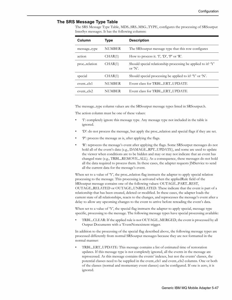
Configuration
The SRS Message Type TableThe SRS Message Type Table, MDS_SRS_MSG_TYPE, configures the processing of SRSoutput InterSys messages. It has the following columns:
The message_type column values are the SRSoutput message types listed in SRSoutput.h.
The action column must be one of these values:
• ‘I’: completely ignore this message type. Any message type not included in the table is ignored.
• ‘D’: do not process the message, but apply the proc_relation and special flags if they are set.
• ‘P’: process the message as is, after applying the flags.
• ‘R’: reprocess the message’s event after applying the flags. Some SRSoutput messages do not hold all of the event’s data (e.g., DAMAGE_RPT_UPDATE), and some are used to update the viewer when conditions are to be hidden and may or may not indicate that an event has changed state (e.g., TRBL_REMOVE_ALL). As a consequence, these messages do not hold all the data required to process them. In these cases, the adapter requests JMService to send all the current data for the message’s event.
When set to a value of ‘Y’, the proc_relation flag instructs the adapter to apply special relation processing to the message. This processing is activated when the appliedRule field of the SRSoutput message contains one of the following values: OUTAGE_PART_REST, OUTAGE_RELATED or OUTAGE_UNRELATED. These indicate that the event is part of a relationship that has been created, deleted or modified. In these cases, the adapter loads the current state of all relationships, reacts to the changes, and reprocesses the message’s event after a delay to allow any upcoming changes to the event to arrive before rereading the event’s data.
When set to a value of ‘Y’, the special flag instructs the adapter to apply special, message type specific, processing to the message. The following message types have special processing available:
• TRBL_CLEAR: If the applied rule is not OUTAGE_MERGED, the event is processed by all Output Documents with a ‘EventNonexistent trigger.
In addition to the processing of the special flag described above, the following message types are processed differently from normal SRSoutput messages because they are not formatted in the normal manner:
• TRBL_ERT_UPDATE: This message contains a list of estimated time of restoration updates. If this message type is not completely ignored, all the events in the message are reprocessed. As this message contains the events’ indexes, but not the events’ classes, the potential classes need to be supplied in the event_cls1 and event_cls2 columns. One or both of the classes (normal and momentary event classes) can be configured. If one is zero, it is ignored.
Column Type Description
message_type NUMBER The SRSoutput message type that this row configures
action CHAR(1) How to process it. ‘I’, ‘D’, ‘P’ or ‘R’.
proc_relation CHAR(1) Should special relationship processing be applied to it? ‘Y’ or ‘N’.
special CHAR(1) Should special processing be applied to it? ‘Y’ or ‘N’.
event_cls1 NUMBER Event class for TRBL_ERT_UPDATE
event_cls2 NUMBER Event class for TRBL_ERT_UPDATE
Generic IBM MQ Mobile Adapter 5-47
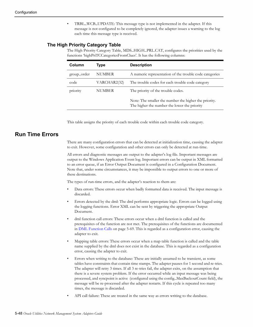
Configuration
• TRBL_WCB_UPDATE: This message type is not implemented in the adapter. If this message is not configured to be completely ignored, the adapter issues a warning to the log each time this message type is received.
The High Priority Category TableThe High Priority Category Table, MDS_HIGH_PRI_CAT, configures the priorities used by the functions ‘highPriTCCategoriesFromClues’. It has the following columns:
This table assigns the priority of each trouble code within each trouble code category.
Run Time ErrorsThere are many configuration errors that can be detected at initialization time, causing the adapter to exit. However, some configuration and other errors can only be detected at run-time.
All errors and diagnostic messages are output to the adapter’s log file. Important messages are output to the Windows Application Event log. Important errors can be output in XML formatted to an error queue, if an Error Output Document is configured in a Configuration Document. Note that, under some circumstances, it may be impossible to output errors to one or more of these destinations.
The types of run-time errors, and the adapter’s reaction to them are:
• Data errors: These errors occur when badly formatted data is received. The input message is discarded.
• Errors detected by the dml: The dml performs appropriate logic. Errors can be logged using the logging functions. Error XML can be sent by triggering the appropriate Output Document.
• dml function call errors: These errors occur when a dml function is called and the prerequisites of the function are not met. The prerequisites of the functions are documented in DML Function Calls on page 5-69. This is regarded as a configuration error, causing the adapter to exit.
• Mapping table errors: These errors occur when a map table function is called and the table name supplied by the dml does not exist in the database. This is regarded as a configuration error, causing the adapter to exit.
• Errors when writing to the database: These are initially assumed to be transient, as some tables have constraints that contain time stamps. The adapter pauses for 1 second and re-tries. The adapter will retry 3 times. If all 3 re-tries fail, the adapter exits, on the assumption that there is a severe system problem. If the error occurred while an input message was being processed, and syncpoint is active (configured using the config_MaxBackoutCount field), the message will be re-processed after the adapter restarts. If this cycle is repeated too many times, the message is discarded.
• API call failure: These are treated in the same way as errors writing to the database.
Column Type Description
group_order NUMBER A numeric representation of the trouble code categories
code VARCHAR2(32) The trouble codes for each trouble code category
priority NUMBER The priority of the trouble codes.
Note: The smaller the number the higher the priority. The higher the number the lower the priority
5-48 Oracle Utilities Network Management System Adapters Guide

Configuration
DML Examples
An Output DocumentThe following is an example of an Output Document that generates a create request document for a small MDS order. Various lines are numbered to allow reference to them in the explanation below. The numbers are not part of the syntax.
1OutputDoc Job2queue=$G.OutRequestQueue; associate=O; persist="Y";3triggerCreate< SRSoutput; > = isIn($E.status, "ACK", "ASN", "ENR", "RST") &&
($E.outageHdl.cls != $G.momentary) &&!findOrder(event, $E.outageHdl);
4triggerUpdate:S < SRSoutput; > = findOrder(event, $E.outageHdl) && (!isIn($E.status, "UNA", "CNL"));
5{6@docType = ChangeJob;7if (triggerCreate)8{9@docType = CreateJob;10createOrder();11}12&RootElement<environment = $G.environment; revision = "1.0.0";> = @docType;13&ApplicationArea14{15&Sender16{17 &Component = NMS;18 &Confirmation = "Always";19 &AuthorizationId = "NMS Interface";20}21&CreationDateTime = formatDTNow();22@BODId = getGuid();23&BODId = @BODId;24}25&DataArea26{27&ExternalNumber = "NMS:"+ $E.outageHdl.idx;28# CreationDateTime is outageTime which is 29# either when the first customer called30# or when the device was opened in the model31&CreationDateTime=formatDateTime($E.outageTime);32&Device:S = $E.devAlias;33&Address:S = substring($E.dispAddress, 0, 100);34sqlselect @devPhases, @fuseSize, @winter_load, @summer_load |
phase_designation, fuse_size, kva_lod_win, kva_lod_sumr |classTable($E.devHdl.cls) | "where h_idx = " | $E.devHdl.idx;
35&DevPhases = @devPhases;36&FuseSize = @fuseSize;37&WinterLoad = @winter_load;38&SummerLoad = @summer_load;39&NumCustOut:S = $E.customersOut;40&CallerName = $I.0.getCustomerName;41&CallerAddr = $I.0.getAddrStreet + “ “ + $I.0.getAddrCity;42&CallerPhone = $I.0.getCustomerPhone;43&CallerClues = $I.0.getShortDesc;44&CallerDevice = $I.0.getDeviceAlias;45}46$O.BODId = @BODId;47}
Generic IBM MQ Mobile Adapter 5-49

Configuration
Line 1 declares the document to be an output document named ‘Job’. The name is used in diagnostics, and when a document is invoked in a ‘triggerOutputDoc’ function call (see below).
Line 2 contains three specifications, and illustrates that more than one specification can be placed on one line.
• The first specifies the message queue that the document will be sent out on. The specification assigns the queue to be the value of the external data field named ‘OutRequestQueue’ in the global configuration object. The queue name is available to the rest of the document in the variable ‘@queue’, and could be changed, if required.
• The second associates the document with the order object. Therefore this document will be used to hold the values of all the elements to be used for change detection when the event is updated with an SRSoutput message.
• The third specifies that the message should be marked as persistent when placed on the queue. Not yet delivered messages are lost when the MQ server stops, if they are not marked as persistent.
Line 3 specifies a trigger, named ‘triggerCreate’ for the document, which causes an order to be created. It does not have the ‘send on change’ flag, so change detection is not in effect when this trigger is fired. The trigger specification, between ‘<’ and ‘>’ indicates when the trigger should be evaluated to determine whether it should be fired. In this case the arrival of an asynchronous SRSoutput message causes the trigger to be evaluated. The expression following the ‘=’ is a boolean expression that fires the trigger when it evaluates to true. There may be more than one trigger for an output document. The values of the triggers are available to the rest of the document in variables with the same names as the triggers.
Line 3 also illustrates that a specification can span multiple lines.
Line 4 specifies a trigger, named ‘triggerUpdate’ for the document, which causes an order to be updated after it has been created. It has the ‘send on change’ flag, so change detection is in effect when this trigger is fired. The trigger specification, between ‘<’ and ‘>’ indicates when the trigger should be evaluated to determine whether it should be fired. In this case the arrival of an asynchronous SRSoutput message causes the trigger to be evaluated. The expression following the ‘=’ is a boolean expression that fires the trigger when it evaluates to true. There may be more than one trigger for an output document. The values of the triggers are available to the rest of the document in variables with the same names as the triggers.
The ‘{‘ on line 5 and the ‘}’ on line 47 enclose the body of the document.
Line 6 sets a default value for the variable @docType, which will be used later to set the root element tag.
Line 7 controls whether lines 9 and 10 are evaluated, depending on which trigger fired. If the triggerCreate trigger fired, 9 and 10 will be evaluated.
Line 9 changes the value of the @docType variable to reflect that the order is new.
Line 10 creates a new order object to save the values of the element’s data for change detection.
Line 12 contains the root element tag and attributes. The root element differs from other elements in that the element’s tag is specified by the value of the expression to the right hand side of the ‘=’, in this case the value of the variable @docType. The reason for this is so that the same output document can be used for multiple message types, for example to create an order and to update the order. In this example, the ‘environment’ attribute is set to the value of the external data field named ‘environment’ in the global configuration object. The root element statement can be anywhere in the output document. All other elements appear in the generated XML in the order that they are within the output document.
Lines 13 to 24 define the ‘ApplicationArea’ element, with 3 sub-elements, one of which has 3 sub-elements.
5-50 Oracle Utilities Network Management System Adapters Guide

Configuration
The elements on lines 17 to 19 show how constants can be declared. On line 17 the ‘NMS’ is not surrounded by double quotes ("), because it only contains alphanumeric characters. On line 18 the ‘Always’ is surrounded by quotes, this acceptable, but not necessary because it only contains alphanumeric characters. On line 19 the ‘NMS Interface’ must be surrounded by quotes, because it contains a space.
The value of the element on line 21 is supplied by the ‘formatDTNow’ function that formats the current data and time BOD format CCYY-MM-DDThh:mm:ss.
Line 22 assigns a globally unique id to the variable ‘BODId’ for use on lines 23 and 46.
Lines 25 to 45 define the ‘DataArea’ element, with 15 sub-elements.
Line 27 assigns the concatenation of a constant (in quotes) with the event’s index.
Lines 28 to 30 are comments and are ignored. Everything between a ‘#’ and the end of a line, inclusive, is a comment and is ignored.
Line 31’s element is assigned the time the outage began in the format CCYY-MM-DDThh:mm:ss.
Line 32’s element is assigned the alias (name) of the event’s interrupting device. Because the ‘send on change’ flag (S) is present, a change to this element’s data will cause the XML to be sent to the MDS.
Line 33’s element is assigned the address of the event, truncated to 100 characters. Because the ‘send on change’ flag (S) is present, a change to this element’s data will cause the XML to be sent to the MDS.
Line 34 reads four columns of the interrupting device’s facilities (attribute) table. The function ‘classTable’ supplies the name of the table.
Lines 35 to 38 assigns the values read from the database in line 33 to the appropriate elements.
Line 39’s element is set to the number of customers affected by the outage. Because the ‘send on change’ flag (S) is present, a change to this element’s data will cause the XML to be sent to the MDS.
Lines 40 to 44 use the external object ‘Incidents’ to access customer call data. As there are potentially many incidents associated with an event, the dml has to specify which incident to use. The second component of the name, between the first and second period (.) is the offset into the array of incidents, in this case zero. The last component of the name is the name of the data access method in the Incident class. These examples access the first customer’s name, street address, city, phone number, clues, and transformer name. The incidents are normally ordered by the time that they called to report a problem, with the oldest first. If another ordering is required, by total priority for example, the sortIncidents() function can be used to change the order.
Line 46 saves the document’s globally unique id in the external object for use later in another document.
The XML generated by this output document would look similar to the following:
<CreateJob environment="Test" revision="1.0.0"> <ApplicationArea> <Sender> <Component>NMS</Component> <Confirmation>Always</Confirmation> <AuthorizationId>NMS Interface</AuthorizationId> </Sender> <CreationDateTime>2003-05-01T13:36:13-05:00</CreationDateTime> <BODId>guid</BODId> </ApplicationArea> <DataArea> <ExternalNumber>NMS2010</ExternalNumber> <CreationDateTime>2003-05-01T13:26:13-05:00</CreationDateTime>
Generic IBM MQ Mobile Adapter 5-51

Configuration
<Device>XFM12345678</Device> <Address>5800 Yonge St. North York</Address> <DevPhases>A</DevPhases> <FuseSize>100</FuseSize> <WinterLoad>40</WinterLoad> <SummerLoad>45</SummerLoad> <NumCustOut>4</NumCustOut> <CallerName>M.J. McLaughlin</CallerName> <CallerAddr>5802 Yonge St. North York</CallerAddr> <CallerPhone>416 555-1212</CallerPhone> <CallerClues>NC</CallerClues> <CallerDevice>XFM12345678</CallerDevice> </DataArea></CreateJob>
An Input DocumentThe following is an example of an Input Document that processes a document containing completion data for an order. Various lines are numbered to allow reference to them in the explanation below. The numbers are not part of the syntax.
1 InputDoc CompletionData2 queue=$G.InRequestQueue;3 &RootElement<environment=$G.environment; revision="1.0.0";> =4 FieldReportSave;5 BasePath=DataArea;6 {7 &JobNumber:R;8 &Crew9 {10 &CrewKey11 {12 &CrewName::"MDS";13 }14 }15 &CompletionData16 {17 &System:R;18 &Type:R;19 &Failure:R;20 &Cause:R;21 &InterruptDev:R;22 &Action:R;23 &OtherAction::Other;24 &RestoredTime;25 &CustomerCaseNotes:::CCN;26 }2728 if (!findOrder(externalId, &JobNumber))29 {30 stop;31 }3233 @action=(&CompletionData/Action == "Other")
? &CompletionData/OtherAction: &CompletionData/Action;
34 @restoredTime = decodeDateTime(&CompletionData/RestoredTime);35 sqlupdate picklist_info_upd_tr |
system_om, type_om,failure_om, cause_om,
5-52 Oracle Utilities Network Management System Adapters Guide
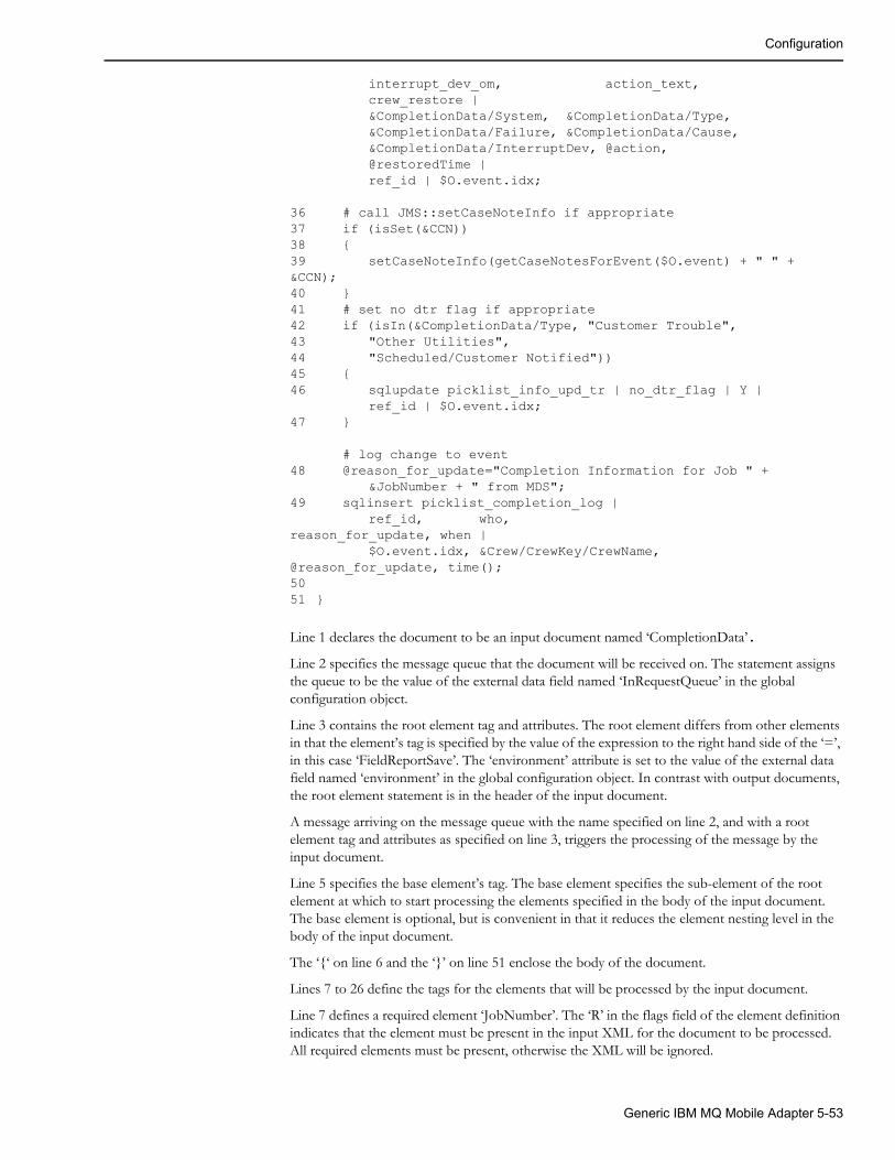
Configuration
interrupt_dev_om, action_text,crew_restore |&CompletionData/System, &CompletionData/Type,&CompletionData/Failure, &CompletionData/Cause,&CompletionData/InterruptDev, @action,@restoredTime |ref_id | $O.event.idx;
36 # call JMS::setCaseNoteInfo if appropriate37 if (isSet(&CCN))38 {39 setCaseNoteInfo(getCaseNotesForEvent($O.event) + " " + &CCN);40 }41 # set no dtr flag if appropriate42 if (isIn(&CompletionData/Type, "Customer Trouble",43 "Other Utilities", 44 "Scheduled/Customer Notified"))45 {46 sqlupdate picklist_info_upd_tr | no_dtr_flag | Y |
ref_id | $O.event.idx;47 }
# log change to event48 @reason_for_update="Completion Information for Job " +
&JobNumber + " from MDS";49 sqlinsert picklist_completion_log |
ref_id, who,reason_for_update, when |
$O.event.idx, &Crew/CrewKey/CrewName, @reason_for_update, time();5051 }
Line 1 declares the document to be an input document named ‘CompletionData’.
Line 2 specifies the message queue that the document will be received on. The statement assigns the queue to be the value of the external data field named ‘InRequestQueue’ in the global configuration object.
Line 3 contains the root element tag and attributes. The root element differs from other elements in that the element’s tag is specified by the value of the expression to the right hand side of the ‘=’, in this case ‘FieldReportSave’. The ‘environment’ attribute is set to the value of the external data field named ‘environment’ in the global configuration object. In contrast with output documents, the root element statement is in the header of the input document.
A message arriving on the message queue with the name specified on line 2, and with a root element tag and attributes as specified on line 3, triggers the processing of the message by the input document.
Line 5 specifies the base element’s tag. The base element specifies the sub-element of the root element at which to start processing the elements specified in the body of the input document. The base element is optional, but is convenient in that it reduces the element nesting level in the body of the input document.
The ‘{‘ on line 6 and the ‘}’ on line 51 enclose the body of the document.
Lines 7 to 26 define the tags for the elements that will be processed by the input document.
Line 7 defines a required element ‘JobNumber’. The ‘R’ in the flags field of the element definition indicates that the element must be present in the input XML for the document to be processed. All required elements must be present, otherwise the XML will be ignored.
Generic IBM MQ Mobile Adapter 5-53

Configuration
Line 12 defines an optional element ‘CrewName’, a sub-element of ‘CrewKey’, which is in turn a sub-element of ‘Crew’. The element has a default value of ‘MDS’, which is the value used by references to the element in the rest of the document, when the element is not present. If a default value is not present, missing elements have a value of the empty string.
Lines 15 to 26 define the ‘CompletionData’ element, which has 9 sub-elements, some of which are required.
If all the required elements are present, the data can be processed.
Line 28 calls the ‘findOrder’ function that finds the order object with an ‘externalId’ field equal to the JobNumber supplied in the XML. This function returns a boolean indicating whether such an order object was found, or not. This result is inverted by the ‘!’ so that line 30 is executed if ‘findOrder’ fails. Line 30 is a stop statement, which causes the processing of the document to terminate.
Line 33 sets the variable ‘action’ to either the contents of the ‘OtherAction’ element or the ‘Action’ element, depending on whether ‘Action’ has a value of ‘Other’ or not. Both these elements are sub-elements of the ‘CompletionData’ element. A reference to a sub-element takes the form ‘&grandparent/parent/subelement’.
Alternatively, an element can be named to make the references more succinct. The element definition of ‘CustomerCareNotes’ with a name of ‘CCN” on line 25, and the references to it on lines 37 and 39 are an example of this.
Line 34 converts the time in the element ‘RestoredTime’ into a format suitable to be passed to the database, and saves it in the variable ‘restoredTime’.
Line 35 saves the values of 5 elements and 2 variables in the ‘picklist_info_upd_tr’ table in the database using a sqlupdate statement. This table has a key column ‘ref_id’ that is set to the order’s event’s index number. If aggregate processing has been configured, and the intention is to save the data in the database for all events in the aggregation, the function ‘picklistInfoUpdTr’ would be more appropriate.
Line 37 tests whether the element named ‘CCN’ (the ‘CustomerCaseNotes’ element in ‘CompletionData’), was present in the input XML, using the function ‘isSet’. If the element was set line 39 is executed . The function call to ‘getCaseNotesForEvent’ in the parameter list of the call to ‘setCaseNoteInfo’, calls an Oracle Utilities Network Management System API to read the current value of the order’s event case notes. The value returned is concatenated with a space and the value of the CCN element. The resulting value is saved to the event’s case notes using the function ‘setCaseNoteInfo’.
Lines 42 to 47 set the ‘no_dtr_flag’ column in the ‘picklist_info_upd_tr’ table to ‘Y’, if the ‘CompletionData/Type’ element indicates that the trouble was not with the utility’s equipment. The function ‘isIn’ returns true if its first parameter matches any one of the rest of its parameters, false otherwise
Lines 48 and 49 logs the change to the event by inserting a row into the picklist_completion_log table. If aggregate processing has been configured, and the intention is to save the data in the database for all events in the aggregation, the function ‘picklistCompLog’ would be more appropriate.
The following XML would be processed by the example input document
<FieldReportSave environment="Test" revision="1.0.0"> <ApplicationArea> <Sender> <Component>MDS</Component> <Confirmation>Never</Confirmation> <AuthorizationId>MDS Interface</AuthorizationId> </Sender> <CreationDateTime>2003-05-01T14:30:17-05:00</CreationDateTime> <BODId>guid</BODId>
5-54 Oracle Utilities Network Management System Adapters Guide

DML Reference
</ApplicationArea> <DataArea> <JobNumber>MDS7704</JobNumber> <CompletionData> <System>4KV</System> <Type>Lateral</Type> <Failure>Fuse</Failure> <Cause>Animal</Cause> <InterruptDev>XFM12345678</InterruptDev> <Action>Fuse replaced</Action> <CustomerCaseNotes>Temporary Repair: Scheduled for Tuesday</CustomerCaseNotes> </CompletionData> </DataArea></FieldReportSave>
DML ReferenceThis section contains a full reference for the dynamic message language used in the Generic IBM MQ Mobile Adapter configuration dml files.
Lexical ConventionsA dml configuration consists of one or more files. Each file is processed in turn to generate a sequence of tokens, which are further processed into internal data structures used at run time to generate XML documents and process XML documents.
Syntax notationIn the syntax notation used in this Appendix, syntactic categories are indicated by italic type, and literal words and characters in bold type. An optional part of the syntax is indicated by enclosing it in square brackets ([]). An ellipsis (…) indicates that the preceding part of the syntax can be optionally repeated an arbitrary number of times.
TokensThere are seven kinds of tokens: names, strings, quoted strings, keywords, operators, and other separators. Blanks, tabs, line feeds, carriage returns, and comments (described below), are ignored except as they serve to separate tokens. Some white space is required to separate otherwise adjacent tokens.
CommentsThe character # starts a comment which terminates at the end of the line on which it occurs.
Include DirectiveThe include directive can appear anywhere in an input file and takes the form:
include file name
The contents of the file name are processed as if they replaced the include directive itself.
Generic IBM MQ Mobile Adapter 5-55
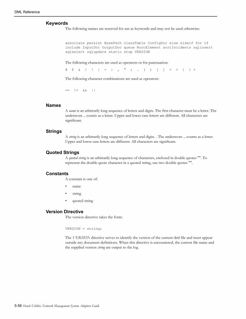
DML Reference
KeywordsThe following names are reserved for use as keywords and may not be used otherwise:
associate persist BasePath classTable ConfigDoc else elseif for if include InputDoc OutputDoc queue RootElement sortIncidents sqlinsert sqlselect sqlupdate static stop VERSION
The following characters are used as operators or for punctuation:
@ $ & / ! | = : , “ ; . ( ) [ ] < > { } +
The following character combinations are used as operators:
== != && ||
NamesA name is an arbitrarily long sequence of letters and digits. The first character must be a letter. The underscore _ counts as a letter. Upper and lower case letters are different. All characters are significant.
StringsA string is an arbitrarily long sequence of letters and digits. . The underscore _ counts as a letter. Upper and lower case letters are different. All characters are significant.
Quoted StringsA quoted string is an arbitrarily long sequence of characters, enclosed in double quotes "". To represent the double quote character in a quoted string, use two double quotes "".
ConstantsA constant is one of:
• name
• string
• quoted string
Version DirectiveThe version directive takes the form:
VERSION = string;
The VERSION directive serves to identify the version of the current dml file and must appear outside any document definitions. When this directive is encountered, the current file name and the supplied version string are output to the log.
5-56 Oracle Utilities Network Management System Adapters Guide

DML Reference
Basic Concepts
Type(s)DML is a typeless language, or perhaps more accurately, a singly typed language. All values consist of character strings. DML has no concept of numbers. To illustrate this, strings can be used to pass positive integers to functions. For example:
@truncatedString = substring(@address, 0, 100);
However, quoted strings must be used to pass negative integers. For example:
@lastCharacter = substring(@characters, "-1", 1);
It should be emphasized that it is the function, not the dml that is interpreting the character string as an integer.
In certain contexts, a value is used as a boolean, or logical, value. Any non-empty string is considered true, and the empty string (written as "") is considered false. A boolean expression or function returns "Y" when true and "" when false.
Definitions and ReferencesThere are a number of value bearing entities in dml. Apart from one exception (variables), they must be defined before they are referenced. The definition introduces the entity, and defines certain modifiers to the entity. An entity is referenced when its value is used in an expression or when it is assigned to in an assignment statement. When a variable uses the default set of modifiers, it can be implicitly defined when first assigned.
EntitiesThe entities in a document carry values and have modifiers that change their behavior.
VariablesA variable is used to save intermediate results in a document. A variable definition takes the form:
@name:modifiers
The name must be unique amongst the variables within the document. Other entities can have the same name. The :modifiers is optional.
If the :modifiers are not required, variables can be implicitly defined when they are assigned to.
A variable reference takes the form:
@name
Variables can be set and referenced in all document types.
ElementsAn element generates an XML element in Output Documents, and supplies an input XML element value or sub-elements in Input Documents. There are to kinds of element definitions: plain elements and array elements.
plain element definitions and an array element definitions are known collectively as element definitions.
Generic IBM MQ Mobile Adapter 5-57

DML Reference
Plain Element DefinitionsPlain elements are referred to as elements in the rest of this section.
An element definition takes the form:
&name:modifiers < attribute definitions >
The name of an element is its XML tag, and must be unique amongst the elements within its immediately enclosing element or document. Other entities can have the same name. The :modifiers and attribute definitions are optional. The format of attribute definitions is described below in section Attributes on page 5-59. Elements must either have values but no sub-elements or must have sub-elements but no value. (This may be changed in a future version of the adapter).
Array Element DefinitionsArray elements can only appear in Input Documents, and are used when more that one element with the same tag can be sub-elements of the same element in the input XML. An array element definition takes one of two forms: with an unspecified index, and with a specified index attribute.
The unspecified index form is:
&name[]:modifiers < attribute definitions >
The specified index form is:
&name[name]:modifiers < attribute definitions > R(constant list)
where the name in square brackets is the name of the index attribute, and R(constant list) is the required index list, which is optional. The required index list defines the values of the index attribute that must be in the input XML before the enclosing Input Document will be used to process the input XML.
Array element modifiers can only contain an alternate name for the array element.
The name of an array element is its XML tag, and must be unique amongst the elements within its immediately enclosing element or document. Other entities can have the same name. The :modifiers and attribute definitions are optional. The format of attribute definitions is described below in section Attributes on page 5-59. Array Elements must either have values but no sub-elements or must have sub-elements but no value.
Element ReferencesThe values of plain elements with values in Input Documents can be obtained using a plain element reference taking the form:
&element identifier
The element identifier has two forms:
The full element path, which is either the name of the element, if it is not a sub-element of another element, or the full element path of the sub-element’s enclosing element, followed by a slash (/) followed by the element’s name.
The element’s alternate name, which is defined in the element’s modifiers.
If the element has an alternate name, the full element path cannot be used.
The values of individual elements in an array element with values can be obtained using an array element reference taking the form:
&element identifier[index value]
5-58 Oracle Utilities Network Management System Adapters Guide
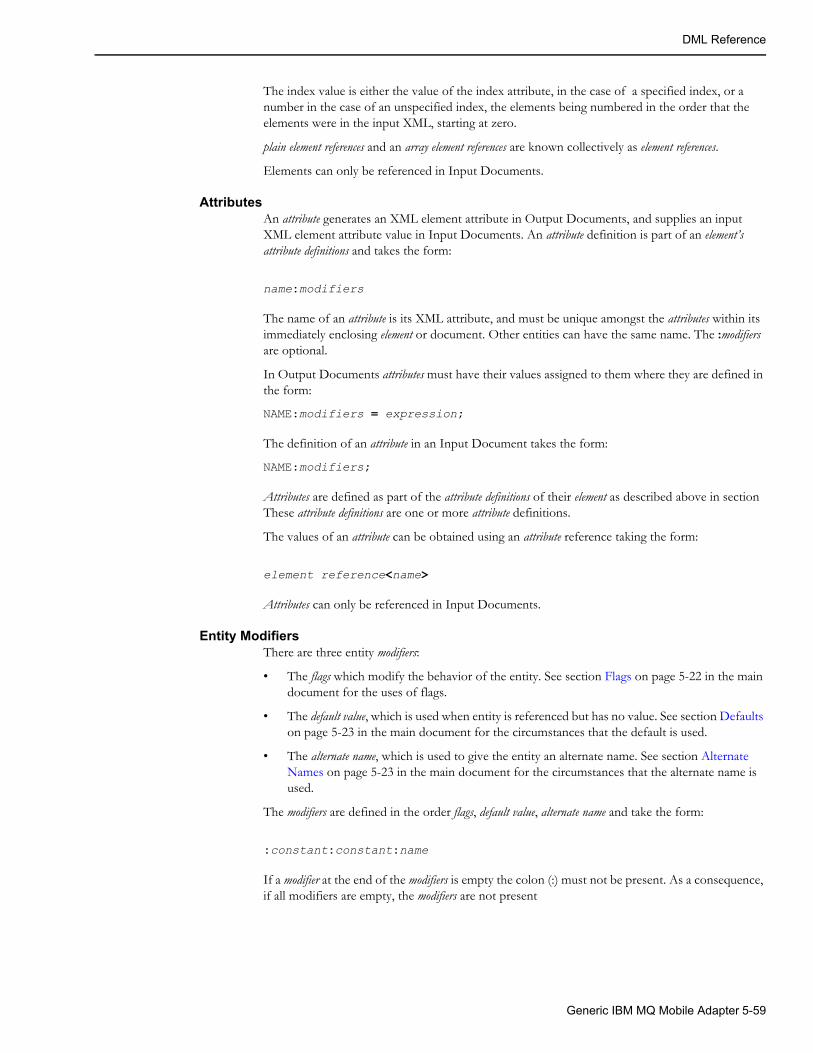
DML Reference
The index value is either the value of the index attribute, in the case of a specified index, or a number in the case of an unspecified index, the elements being numbered in the order that the elements were in the input XML, starting at zero.
plain element references and an array element references are known collectively as element references.
Elements can only be referenced in Input Documents.
AttributesAn attribute generates an XML element attribute in Output Documents, and supplies an input XML element attribute value in Input Documents. An attribute definition is part of an element’s attribute definitions and takes the form:
name:modifiers
The name of an attribute is its XML attribute, and must be unique amongst the attributes within its immediately enclosing element or document. Other entities can have the same name. The :modifiers are optional.
In Output Documents attributes must have their values assigned to them where they are defined in the form:
NAME:modifiers = expression;
The definition of an attribute in an Input Document takes the form:
NAME:modifiers;
Attributes are defined as part of the attribute definitions of their element as described above in section These attribute definitions are one or more attribute definitions.
The values of an attribute can be obtained using an attribute reference taking the form:
element reference<name>
Attributes can only be referenced in Input Documents.
Entity ModifiersThere are three entity modifiers:
• The flags which modify the behavior of the entity. See section Flags on page 5-22 in the main document for the uses of flags.
• The default value, which is used when entity is referenced but has no value. See section Defaults on page 5-23 in the main document for the circumstances that the default is used.
• The alternate name, which is used to give the entity an alternate name. See section Alternate Names on page 5-23 in the main document for the circumstances that the alternate name is used.
The modifiers are defined in the order flags, default value, alternate name and take the form:
:constant:constant:name
If a modifier at the end of the modifiers is empty the colon (:) must not be present. As a consequence, if all modifiers are empty, the modifiers are not present
Generic IBM MQ Mobile Adapter 5-59

DML Reference
External DataExternal data is available from the various external data objects, described above in section The External Objects on page 5-26. All fields in the objects can be read, but some objects or individual fields are read-only, i.e. they cannot be written.
A reference to an external object field takes the form:
$external data object identifier.field name
where the external data object identifier is the letter associated with the object and the field name is the name of the field (note that they are separated by a period (.)). Some fields (for example Handles) have sub-fields. A reference to a sub-field takes the form:
$external data object identifier.field name.sub-field name
Most external objects have one instance at a time, but the Incident Object can have zero, one or more, depending on the number of incidents that have grouped to the current event. To reference an individual incident field, an offset to the incident into the array of incidents is required. This offset starts at zero, and is a constant which must only contain digits, known as an offset. The normal order of incidents is the order that they were received by Oracle Utilities Network Management System. This order can be altered by use of the sortIncidents function. A reference to an incident field takes the form:
$I.offset.field name
Incident references can contain sub-fields.These are known as external field references.
Note that some external object fields are read-only, i.e., they cannot be set by the dml. The read-only status of each external object is listed below:
• The Order Object (‘O’): All the fields listed in section Permanent Order Object Fields on page 5-153, Permanent Order Object Fields on page 5-153 of DML Function Calls on page 5-69 are read-only. All other fields are read/write.
• The Relationship Object (‘R’): All the fields listed in section Permanent Relationship Object Fields on page 5-153, Permanent Relationship Object Fields on page 5-153 of DML Function Calls on page 5-69 are read-only. All other fields are read/write.
• The Event Object (‘E’): All fields are read-only.
• The Incident Object(‘I’): All fields are read-only.
• The Global Data Object (‘G’): All fields are read/write.
• The Trigger Parameter Object (‘T’): All fields are read/write.
FunctionsA function is called using the following form:
name([parameter1] [, parameter2] …)
Where name is the name of the function and parameter2, parameter2, … are expressions. All functions return a value, but in some cases the value is always the empty string, implying that they are only called for their side effects. The functions available and their parameters are described in DML Function Calls on page 5-69.
5-60 Oracle Utilities Network Management System Adapters Guide

DML Reference
ExpressionsAn expression is a combination of dml components that yield a value. Expressions are combined using operators. The following table shows the expressions and the operators:
Note: The logical alternation, AND, and OR expressions are evaluated left to right and expressions that do not need to be evaluated are not evaluated, and any side effects (e.g., due to a function call) do not occur. Specifically:
Alternation: expression1 is evaluated. If it is true only expression2 is evaluated, otherwise only expression3 is evaluated.
AND: expression1 is evaluated. If it is false, expression2 is not evaluated.
OR: expression1 is evaluated. If it is true, expression2 is not evaluated.
Expression Value Notes
constant The constant
variable reference The variable’s current value
element reference The element’s current value
attribute reference The attribute’s current value
external field reference The field’s current value
function The function’s return value
expression1 + expression2 The concatenation of the two expressions
(expression) The expression’s value Used to alter the precedence of operators.
expression1 ? expression2 : expression3
If expression1 is true, expression2.If expression1 is false, expression3.
Logical alternation. See note below.
!expression If expression is true, false.If expression is false, true.
Logical NOT.
expression1 && expression2 true if both expression1 and expression2 are true, false otherwise
Logical AND. See note below.
expression1 || expression2 true if either expression1 or expression2 is true, false otherwise
Logical OR. See note below.
expression1 == expression2 true if expression1 is an exact duplicate of expression2 is true, false otherwise
expression1 != expression2 true if expression1 is not an exact duplicate of expression2 is true, false otherwise
Generic IBM MQ Mobile Adapter 5-61

DML Reference
Lists
Name ListA name list is one or more names separated by commas (,). For example:
h_cls, h_idx
Constant ListA constant list is one or more constants, separated by commas (,). For example:
None, "$%I99", 13, "-3", "This is a ""quoted"" string"
Variable Reference ListsA variable reference list is one or more variable references, separated by commas (,). For example:
@devPhases, @pole_number, @winter_load, @summer_load
Expression ListA expression list is one or more expressions, separated by commas (,). For example:
@a + @b, formatDateTime(@time), $E.outageHdl.idx, none
StatementsStatements are the basic processing units in dml. Many of them are terminated using the statement terminator, ; (semi-colon).
Statement BlocksA number of statements require one or more statements grouped together. This is achieved using a statement block, which takes the form:
{statements
}
Where statements is one or more statements.
Variable Assignment StatementThis statement assigns a value to a variable and takes the form:
variable reference = expression;
Element Definition StatementElement definitions differ between elements with values (simple elements) and those with sub-elements (compound elements). They also differ between those in Output Documents (output elements) and those in Input Documents (input elements). The four flavors are described in the following sections.
Output Element Definition StatementsThese statements are only valid in Output Documents.
Simple Output Element Definition StatementThis statement assigns a value to an element and takes the form:
element definition = expression;
5-62 Oracle Utilities Network Management System Adapters Guide

DML Reference
Compound Output Element Definition StatementThis statement defines an element with one or more sub-elements and takes the form:
element definitionstatement block
The statement block must contain at least one output element definition statement, but can also contain other statements allowed in Output Documents.
Input Element Definition StatementsThese statements are only valid in Input Documents.
Simple Input Element Definition StatementThis statement defines an element that can accept a value from incoming XML documents and takes the form:
element definition;
Compound Input Element Definition StatementThis statement defines an element with sub-elements that can accept values value from incoming XML documents and takes the form:
element definitionstatement block
The statement block can only contain input element definition statements and must contain at least one.
External Data Assignment StatementThis statement assigns a value to an external object field and takes the form:
external field reference = expression;
Function StatementThis statement is used to call a function for its side effects and the return value is either the empty string or can be ignored. It takes the form:
function expression;
SQL Select StatementThis statement is used to read data from the database and takes the form:
sqlselect variable reference list | name list | [static] expression [ | expression …] ;
SQL Insert StatementsThis statement is used to insert a row of data in a database table and takes the form:
sqlinsert expression | name list | expression list ;
Generic IBM MQ Mobile Adapter 5-63

DML Reference
SQL Update StatementsThis statement is used to insert or update a row of data in a database table and takes the form:
sqlupdate expression | name list | expression list | name list | expression list ;
If StatementThis statement is used to alter the flow of expression evaluation, and output element selection, based on the value of an expression. It takes the form:
if (expression)statement block 1
else if (expression)statement block 2
elsestatement block 3
elseif is a synonym for else if.
There can be any number of else if’s, including none. The else is optional.
If the expression of the if is true, it’s statement block (1 in this example) is evaluated.
Otherwise, if the expression of the first else if, if any, is true, it’s statement block (2 in this example) is evaluated.
Otherwise, if the expression of the next else if, if any, is true, it’s statement block is evaluated.
Otherwise, the else’s statement block (3 in this example) is evaluated.
A maximum of one statement block will be evaluated in any if statement.
For Statement This statement is use to iterate through all elements in an array element. It can only appear in an Input Document. It takes the form:
for (&element identifier[], variable reference)statement block
Stop StatementThis statement is used to terminate processing of a document. In addition, it prevents an Output Document from sending its XML. It takes the form:
stop;
Root Element StatementThis statement is used to generate an Output Document’s root element and to select the Input Document or Documents that the input XML can be processed by. In an Output Document it is located in the document’s statement block. In an Input Document it is located in the input document header. It takes the form:
&RootElement [ < attribute definitions > ] = expression ;
5-64 Oracle Utilities Network Management System Adapters Guide

DML Reference
Documents
Output Document HeaderThe output document header consists of the following specifications, in any order.
Queue Specification
This specification specifies the queue to which the Output Document’s XML is directed to, and takes the form:
queue = expression ;
The queue is available to the Output Document’s statement block as a variable named queue, and can be assigned to in the following manner:
@queue = expression ;
The queue specification is optional, and defaults to the empty string. If the queue specification is defaulted, it must be set in the Output Document’s statement block. There may only be a maximum of one queue specification in the header of each Output Document.
Trigger Specification
An Output Document must have at least one trigger specification, and can have an arbitrary number greater than one.
Association Specification
This specification associates the Output Document with an external object, and takes the form:
associate = external data object identifier ;
The only external data object identifier currently supported is O, the Order Object. One and only one Output Document must be associated with the Order Object.
Persistence SpecificationThis specification allows you to set the persistence flag for outgoing messages, and takes the form:
persist = "Y" or "N";
If this specification is omitted, the message will have the default persistence setting configured for the queue it is being placed on.
Output DocumentThis document is used to generate XML and send it to the MDS. It takes the form:
OutputDoc nameoutput document headerstatement block
Input Document HeaderThe input document header consists of one and only one root element statement and the following specifications, in any order.
Generic IBM MQ Mobile Adapter 5-65
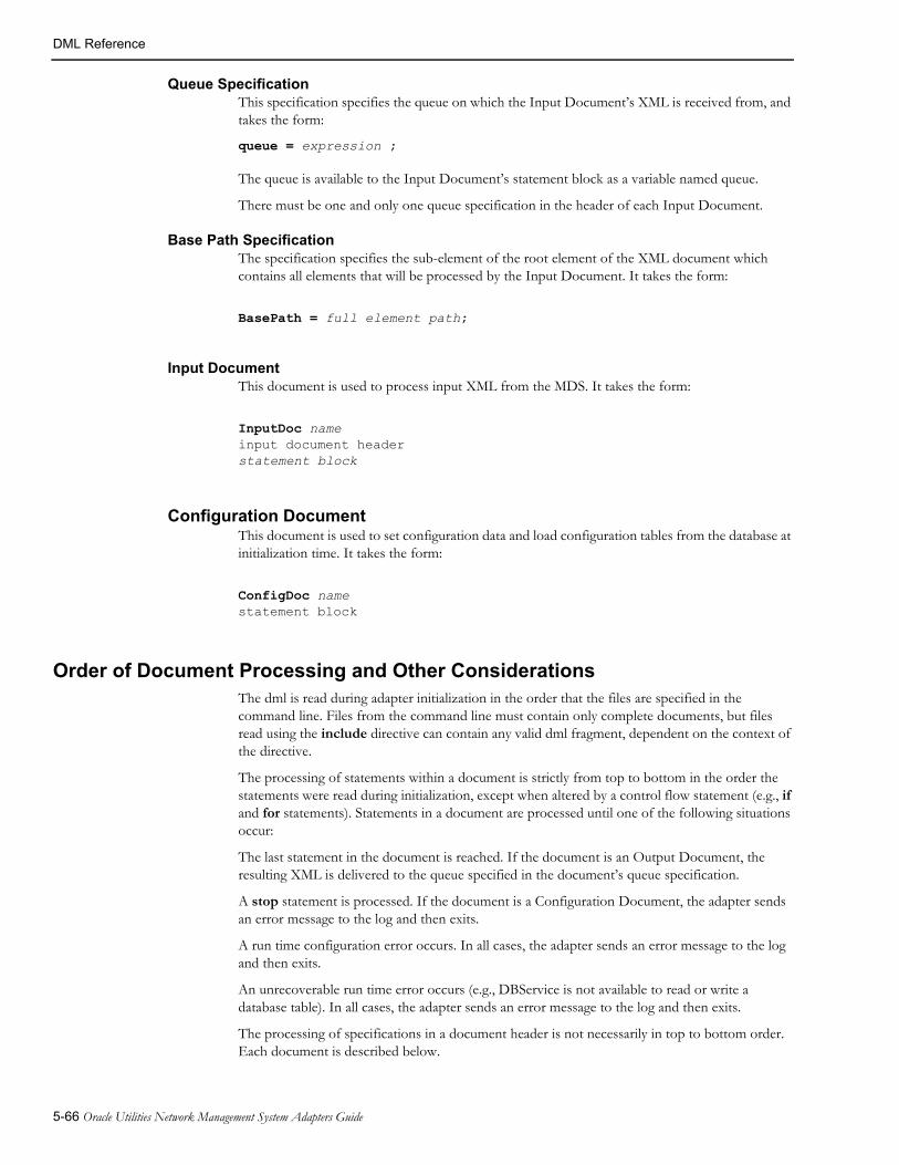
DML Reference
Queue SpecificationThis specification specifies the queue on which the Input Document’s XML is received from, and takes the form:
queue = expression ;
The queue is available to the Input Document’s statement block as a variable named queue.
There must be one and only one queue specification in the header of each Input Document.
Base Path SpecificationThe specification specifies the sub-element of the root element of the XML document which contains all elements that will be processed by the Input Document. It takes the form:
BasePath = full element path;
Input DocumentThis document is used to process input XML from the MDS. It takes the form:
InputDoc nameinput document headerstatement block
Configuration DocumentThis document is used to set configuration data and load configuration tables from the database at initialization time. It takes the form:
ConfigDoc namestatement block
Order of Document Processing and Other ConsiderationsThe dml is read during adapter initialization in the order that the files are specified in the command line. Files from the command line must contain only complete documents, but files read using the include directive can contain any valid dml fragment, dependent on the context of the directive.
The processing of statements within a document is strictly from top to bottom in the order the statements were read during initialization, except when altered by a control flow statement (e.g., if and for statements). Statements in a document are processed until one of the following situations occur:
The last statement in the document is reached. If the document is an Output Document, the resulting XML is delivered to the queue specified in the document’s queue specification.
A stop statement is processed. If the document is a Configuration Document, the adapter sends an error message to the log and then exits.
A run time configuration error occurs. In all cases, the adapter sends an error message to the log and then exits.
An unrecoverable run time error occurs (e.g., DBService is not available to read or write a database table). In all cases, the adapter sends an error message to the log and then exits.
The processing of specifications in a document header is not necessarily in top to bottom order. Each document is described below.
5-66 Oracle Utilities Network Management System Adapters Guide

DML Reference
Output DocumentsOutput Document specifications are processed in the following order:
The association specification is processed once during initialization.
The queue specification is evaluated just before the first statement of the document is processed.
When a trigger event occurs, all Output Documents are examined in top to bottom order to determine whether the event should trigger each document.
If the trigger event’s type matches at least one trigger specification in the document, the triggers of that type are processed in top to bottom order, until one evaluates to true. In this case, all other triggers have their value set to false, even if they have not been processed. If all triggers evaluate to false the document is not processed due to the trigger event.
If the Output Document is triggered, it is fully processed before the next Output Document is examined in order to determine whether the event should trigger the next document.
Input DocumentsAll Input Document header specifications are evaluated at initialization, in the order base path specification, queue specification, and then root element specification.
When an input XML document arrives, each Input Document is examined in top to bottom order to determine whether the XML satisfies the root element specification. If no document matches the incoming XML, the XML is discarded. If at least one Input Document is eligible, the elements in the XML are delivered to the documents in the order they appear in the XML document. Once all elements have been delivered, each document is examined in top to bottom order to determine whether all required elements are present, and are processed in top to bottom order if the elements are present. Once all Input Documents have been processed, the XML is discarded.
Configuration DocumentsConfiguration Documents have no header specifications. All Configuration Documents are processed in top to bottom order. Once they all have been processed successfully, they are discarded.
Ordering of Incidents in the Incident ObjectWhen processing starts for a document, the incidents in the Incident Object are in their normal order, i.e. the order that they were received by Oracle Utilities Network Management System. This order can be changed during the processing of the document by calling the sortIncidents function. The ordering remains the same during the processing, unless sortIncidents is called again. The order is set back to normal when the document processing finishes.
Interactions between ThreadsThe adapter is a multi-threaded process. Therefore more than one document can be processed at the same time, increasing performance. There is at least one thread for Output Document processing, and at least one thread for each Input Document queue. More threads can be configured using a Configuration Document. The adapter uses a number of other threads for internal processing.
This has a number of implications.
While trigger events are queued internally in the order that they occur, and are extracted from this queue in the order that they were queued, there is no guarantee that the Output Documents triggered by these events will complete their processing in the order the events were queued. This means the XML messages may be delivered to the MQSeries queue in an unexpected order. If this behavior is inappropriate, it can be eliminated at the expense of performance by using only one output thread, and by setting the config_Event_QueueDelay configuration parameter to zero.
Generic IBM MQ Mobile Adapter 5-67
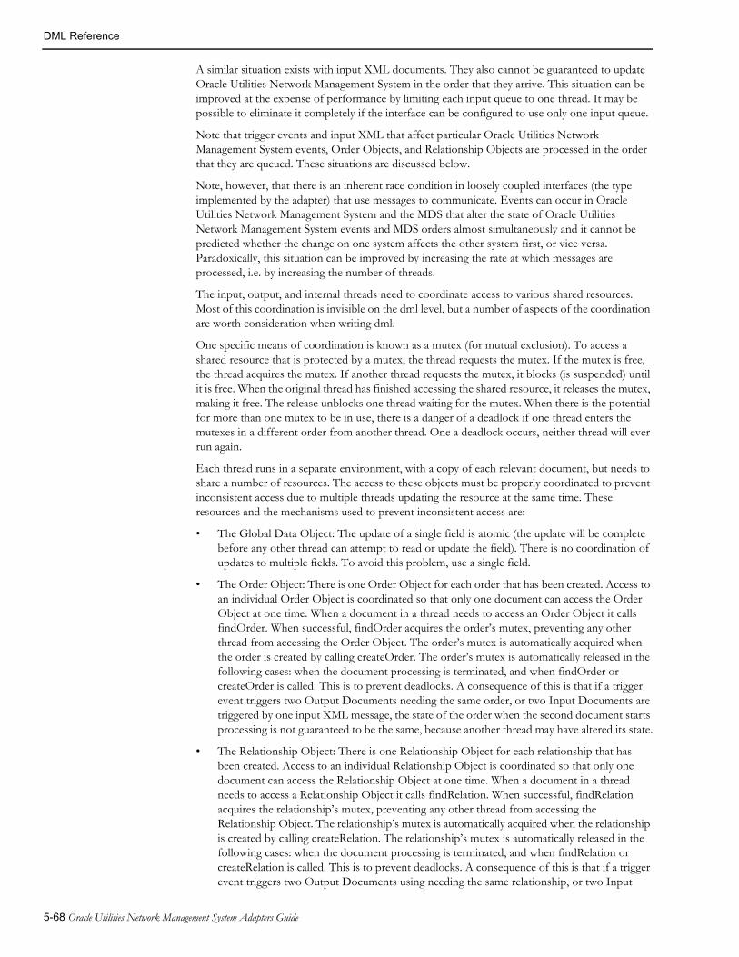
DML Reference
A similar situation exists with input XML documents. They also cannot be guaranteed to update Oracle Utilities Network Management System in the order that they arrive. This situation can be improved at the expense of performance by limiting each input queue to one thread. It may be possible to eliminate it completely if the interface can be configured to use only one input queue.
Note that trigger events and input XML that affect particular Oracle Utilities Network Management System events, Order Objects, and Relationship Objects are processed in the order that they are queued. These situations are discussed below.
Note, however, that there is an inherent race condition in loosely coupled interfaces (the type implemented by the adapter) that use messages to communicate. Events can occur in Oracle Utilities Network Management System and the MDS that alter the state of Oracle Utilities Network Management System events and MDS orders almost simultaneously and it cannot be predicted whether the change on one system affects the other system first, or vice versa. Paradoxically, this situation can be improved by increasing the rate at which messages are processed, i.e. by increasing the number of threads.
The input, output, and internal threads need to coordinate access to various shared resources. Most of this coordination is invisible on the dml level, but a number of aspects of the coordination are worth consideration when writing dml.
One specific means of coordination is known as a mutex (for mutual exclusion). To access a shared resource that is protected by a mutex, the thread requests the mutex. If the mutex is free, the thread acquires the mutex. If another thread requests the mutex, it blocks (is suspended) until it is free. When the original thread has finished accessing the shared resource, it releases the mutex, making it free. The release unblocks one thread waiting for the mutex. When there is the potential for more than one mutex to be in use, there is a danger of a deadlock if one thread enters the mutexes in a different order from another thread. One a deadlock occurs, neither thread will ever run again.
Each thread runs in a separate environment, with a copy of each relevant document, but needs to share a number of resources. The access to these objects must be properly coordinated to prevent inconsistent access due to multiple threads updating the resource at the same time. These resources and the mechanisms used to prevent inconsistent access are:
• The Global Data Object: The update of a single field is atomic (the update will be complete before any other thread can attempt to read or update the field). There is no coordination of updates to multiple fields. To avoid this problem, use a single field.
• The Order Object: There is one Order Object for each order that has been created. Access to an individual Order Object is coordinated so that only one document can access the Order Object at one time. When a document in a thread needs to access an Order Object it calls findOrder. When successful, findOrder acquires the order’s mutex, preventing any other thread from accessing the Order Object. The order’s mutex is automatically acquired when the order is created by calling createOrder. The order’s mutex is automatically released in the following cases: when the document processing is terminated, and when findOrder or createOrder is called. This is to prevent deadlocks. A consequence of this is that if a trigger event triggers two Output Documents needing the same order, or two Input Documents are triggered by one input XML message, the state of the order when the second document starts processing is not guaranteed to be the same, because another thread may have altered its state.
• The Relationship Object: There is one Relationship Object for each relationship that has been created. Access to an individual Relationship Object is coordinated so that only one document can access the Relationship Object at one time. When a document in a thread needs to access a Relationship Object it calls findRelation. When successful, findRelation acquires the relationship’s mutex, preventing any other thread from accessing the Relationship Object. The relationship’s mutex is automatically acquired when the relationship is created by calling createRelation. The relationship’s mutex is automatically released in the following cases: when the document processing is terminated, and when findRelation or createRelation is called. This is to prevent deadlocks. A consequence of this is that if a trigger event triggers two Output Documents using needing the same relationship, or two Input
5-68 Oracle Utilities Network Management System Adapters Guide
DML Reference
Documents are triggered by one input XML message, the state of the relationship when the second document starts processing is not guaranteed to be the same, because another thread may have altered its state. In addition, when findOrder or createOrder is called, the mutex for the order’s relationship is automatically acquired. This has the consequence that calling findOrder or createOrder after calling findRelation causes a configuration error if the order is not in the relationship. Similarly, calling findRelation after calling findOrder or createOrder causes a configuration error if the order is not in the relationship. This behavior is necessary to prevent deadlocks.
• The current event: SRSoutput message for the same event must be processed in the order that they were sent by JMService, otherwise the MDS will not receive up to date data. This prevented by a mutex that is acquired before the SRSoutput message is processed, and released automatically when it has been processed.
DML Function CallsThe importance of meeting the prerequisite specifications for all functions cannot be emphasized too much. If a prerequisite is not met, the adapter will exit with a fatal error message. Some of the prerequisites are written is short form because they are so common. An explanation of how to meet these prerequisites follows:
• The current crew is set: The current crew is set by a successful call to the createCrew function, and by any of the findCrew… functions.
• The current order is set: the current order is set by the createOrder and findOrder functions.
• The current event is set: the current event is set when the current order is set, when an OutputDocument has been triggered by the arrival of an SRSoutput message, and when a call to findEventObject is successful.
• The current damage report is set: the current damage report is set by a call to createDamage, findDamage, findDamageByExternalId, or findOrCreateDamage
In addition, access to the E (event), I (incident), O (order) and R (relation) objects will only work if their prerequisites are met. If these are not met, the adapter does not exit, but all accesses fail, meaning no data can be read or written. Their prerequisites are:
• E: the current event is set.
• I: the current event is set (and it has incidents)
• O: the current order is set.
• R: the current relation is set by a call to findRelation.
Generic IBM MQ Mobile Adapter 5-69
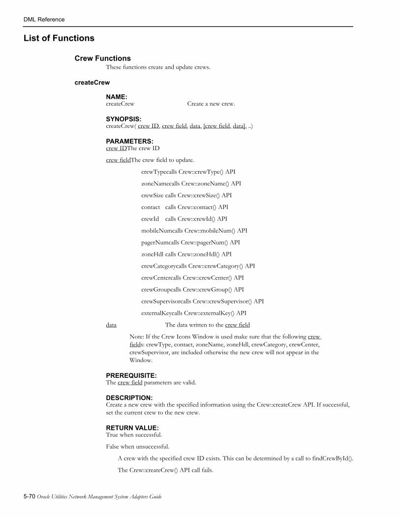
DML Reference
List of Functions
Crew FunctionsThese functions create and update crews.
createCrew
NAME:createCrew Create a new crew.
SYNOPSIS:createCrew( crew ID, crew field, data, [crew field, data], ..)
PARAMETERS:crew IDThe crew ID
crew fieldThe crew field to update.
crewTypecalls Crew::crewType() API
zoneNamecalls Crew::zoneName() API
crewSize calls Crew::crewSize() API
contact calls Crew::contact() API
crewId calls Crew::crewId() API
mobileNumcalls Crew::mobileNum() API
pagerNumcalls Crew::pagerNum() API
zoneHdl calls Crew::zoneHdl() API
crewCategorycalls Crew::crewCategory() API
crewCentercalls Crew::crewCenter() API
crewGroupcalls Crew::crewGroup() API
crewSupervisorcalls Crew::crewSupervisor() API
externalKeycalls Crew::externalKey() API
data The data written to the crew field
Note: If the Crew Icons Window is used make sure that the following crew fields: crewType, contact, zoneName, zoneHdl, crewCategory, crewCenter, crewSupervisor, are included otherwise the new crew will not appear in the Window.
PREREQUISITE:The crew field parameters are valid.
DESCRIPTION:Create a new crew with the specified information using the Crew::createCrew API. If successful, set the current crew to the new crew.
RETURN VALUE:True when successful.
False when unsuccessful.
A crew with the specified crew ID exists. This can be determined by a call to findCrewById().
The Crew::createCrew() API call fails.
5-70 Oracle Utilities Network Management System Adapters Guide

DML Reference
Note that the current crew is not set if the call fails.
DIAGNOSTICS:Error messages are output to the error log.
deleteCrew
NAME:deleteCrew Deletes the crew with the specified crew ID
SYNOPSIS:deleteCrew( crewID )
PARAMETERS:crewID The crew ID.
PREREQUISITE:None.
DESCRIPTION:Deletes the crew with the specified crew ID.
RETURN VALUE:True when successful.
False when unsuccessful.
DIAGNOSTICS:None.
findCrewById
NAME:findCrewById Find an active or inactive crew based on its crew ID
SYNOPSIS:findCrewById( crew ID )
PARAMETERS:crew ID The crew ID.
PREREQUISITE:None.
DESCRIPTION:Find the crew with the specified crew ID.
RETURN VALUE:True when successful. The current crew is set to the crew that was found.
False when unsuccessful.
DIAGNOSTICS:None.
Generic IBM MQ Mobile Adapter 5-71

DML Reference
findCrewByExternalKey
NAME: findCrewByExternalKey Find an active or inactive crew based on its external key
SYNOPSIS: findCrewByExternalKey( externalKey )
PARAMETERS: externalKey The external key.
PREREQUISITE:None.
DESCRIPTION:Find the crew with the specified external key.
RETURN VALUE:True, when successful. The current crew is set to the crew that was found.
False when unsuccessful.
DIAGNOSTICS:Error messages are output to the error log.
findCrewByIdSubStr
NAME:findCrewByIdSubStr Find an active or inactive crew based on a substring of the crew ID
SYNOPSIS:findCrewByIdSubStr( string )
PARAMETERS:string A string.
PREREQUISITE:None.
DESCRIPTION:Find a crew whose crew ID contains the string.
RETURN VALUE:True when successful. The current crew is set to the crew that was found.
False when unsuccessful.
DIAGNOSTICS:None.
5-72 Oracle Utilities Network Management System Adapters Guide
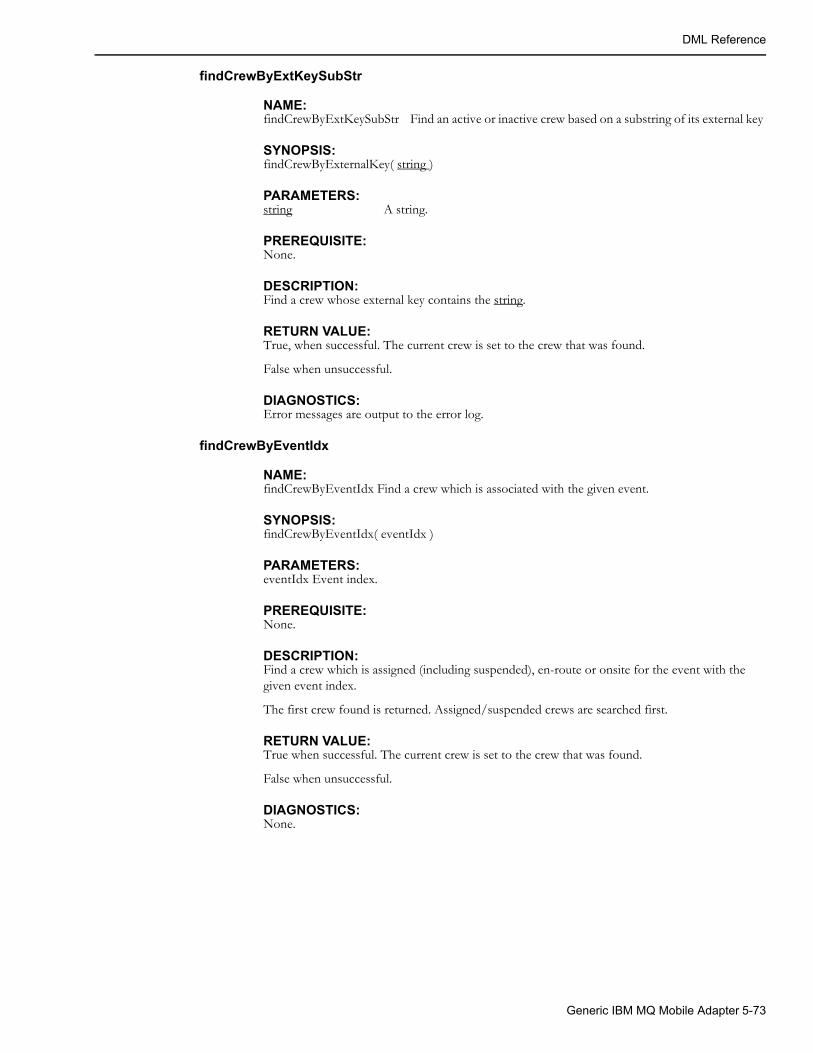
DML Reference
findCrewByExtKeySubStr
NAME:findCrewByExtKeySubStr Find an active or inactive crew based on a substring of its external key
SYNOPSIS:findCrewByExternalKey( string )
PARAMETERS:string A string.
PREREQUISITE:None.
DESCRIPTION:Find a crew whose external key contains the string.
RETURN VALUE:True, when successful. The current crew is set to the crew that was found.
False when unsuccessful.
DIAGNOSTICS:Error messages are output to the error log.
findCrewByEventIdx
NAME:findCrewByEventIdx Find a crew which is associated with the given event.
SYNOPSIS:findCrewByEventIdx( eventIdx )
PARAMETERS:eventIdx Event index.
PREREQUISITE:None.
DESCRIPTION:Find a crew which is assigned (including suspended), en-route or onsite for the event with the given event index.
The first crew found is returned. Assigned/suspended crews are searched first.
RETURN VALUE:True when successful. The current crew is set to the crew that was found.
False when unsuccessful.
DIAGNOSTICS:None.
Generic IBM MQ Mobile Adapter 5-73
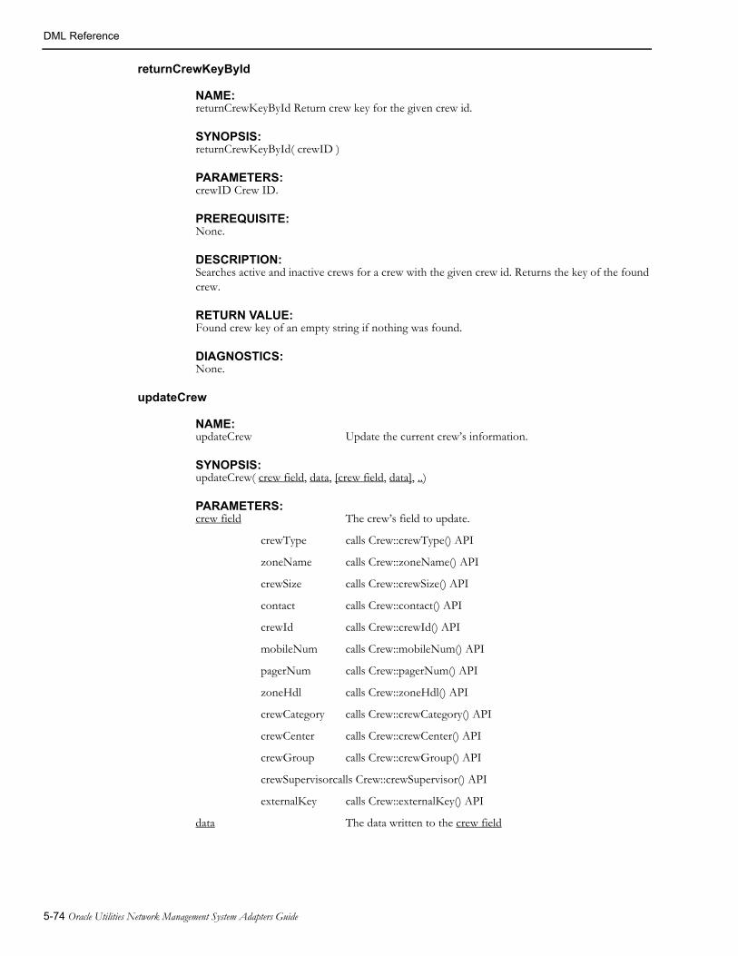
DML Reference
returnCrewKeyById
NAME:returnCrewKeyById Return crew key for the given crew id.
SYNOPSIS:returnCrewKeyById( crewID )
PARAMETERS:crewID Crew ID.
PREREQUISITE:None.
DESCRIPTION:Searches active and inactive crews for a crew with the given crew id. Returns the key of the found crew.
RETURN VALUE:Found crew key of an empty string if nothing was found.
DIAGNOSTICS:None.
updateCrew
NAME:updateCrew Update the current crew’s information.
SYNOPSIS:updateCrew( crew field, data, [crew field, data], ..)
PARAMETERS:crew field The crew’s field to update.
crewType calls Crew::crewType() API
zoneName calls Crew::zoneName() API
crewSize calls Crew::crewSize() API
contact calls Crew::contact() API
crewId calls Crew::crewId() API
mobileNum calls Crew::mobileNum() API
pagerNum calls Crew::pagerNum() API
zoneHdl calls Crew::zoneHdl() API
crewCategory calls Crew::crewCategory() API
crewCenter calls Crew::crewCenter() API
crewGroup calls Crew::crewGroup() API
crewSupervisorcalls Crew::crewSupervisor() API
externalKey calls Crew::externalKey() API
data The data written to the crew field
5-74 Oracle Utilities Network Management System Adapters Guide

DML Reference
PREREQUISITE:The current crew is set.
The crew field parameters are valid.
DESCRIPTION:Update the current crew’s crew field with data and invoke the Crew::commit() API to commit the changes.
RETURN VALUE:True when successful.
False when unsuccessful.
The Crew::commit() API call fails.
DIAGNOSTICS:Error messages are output to the error log.
dispatchCrew
NAME:dispatchCrew Dispatch the current crew to the current order
SYNOPSIS:dispatchCrew()
PARAMETERS:None.
PREREQUISITE:The current crew is set.
The current order is set.
DESCRIPTION:If the crew is already dispatched to another event, the previous dispatch is changed to an assignment.
Invoke the Crew::dispatch() API for the order’s active event. If the order is aggregated, assign the crew to the other events.
RETURN VALUE:The empty string.
DIAGNOSTICS:Error messages are output to the error log.
arriveCrew
NAME:arriveCrew Update the current crew’s information to reflect that the crew has
arrived on site for an order.
SYNOPSIS:arriveCrew()
arriveCrew(time)
PARAMETERS:time The time the crew arrived in internal format. If this parameter is not
supplied, the current time is used.
Generic IBM MQ Mobile Adapter 5-75
DML Reference
PREREQUISITE:The current crew is set.
The current order is set.
DESCRIPTION:If the crew is not dispatched to the order, the crew is dispatched to the order, using the logic described in the description of the ‘dispatchCrew’ function.
If the time is zero or invalid it is set to the current time
Invoke the CrewDispatch::arrived() API for the order’s active event.
RETURN VALUE:The empty string.
DIAGNOSTICS:Error messages are output to the error log.
assignCrew
NAME:assignCrew Assign the current crew to the current order
SYNOPSIS:assignCrew()
PARAMETERS:None.
PREREQUISITE:The current crew is set.
The current order is set.
DESCRIPTION:If the crew is dispatched to the order, undispatch it.
Invoke the Crew::assign() API for all events associated with the order.
RETURN VALUE: The empty string.
DIAGNOSTICS:Error messages are output to the error log.
assignCrewsToAllRelatedEvents
NAME:assignCrewsToAllRelatedEvents
SYNOPSIS:assignCrewsToAllRelatedEvents()
PARAMETERS:None.
PREREQUISITE:The current relation is set.
5-76 Oracle Utilities Network Management System Adapters Guide

DML Reference
DESCRIPTION:This function makes sure that if a crew is assigned to one of the related events then it is also assigned to all of the event which are part of the same relation.
RETURN VALUE: 'Y' on success, the empty string in current relation is not set.
DIAGNOSTICS:Error messages are output to the error log.
unassignCrew
NAME:unassignCrew Unassign the current crew from the current order
SYNOPSIS:unassignCrew()
PARAMETERS:None.
PREREQUISITE:The current crew is set.
The current order is set.
DESCRIPTION:If the crew is assigned or dispatched to any events associated with the order, invoke the Crew::unassign() API or Crew::undispatch API, respectively, for the events.
RETURN VALUE:The empty string.
DIAGNOSTICS:Error messages are output to the error log.
unassignCrewByKey
NAME:unassignCrewByKey Unassign the crew with the given crew key from the current order
SYNOPSIS:unassignCrewByKey(crewKey)
PARAMETERS:crewKey crew key
PREREQUISITE:The current order is set.
DESCRIPTION:Unassign the crew with the given crew key from any events associated with the current order.
RETURN VALUE:The empty string.
DIAGNOSTICS:Error messages are output to the error log.
Generic IBM MQ Mobile Adapter 5-77

DML Reference
suspendCrew
NAME:suspendCrew Suspends the current crew from the current order
SYNOPSIS:suspendCrew()
PARAMETERS:None.
PRE-REQUISITE:The current crew is set.
The current order is set.
DESCRIPTION:Suspends the current crew from the current order.
RETURN VALUE:The empty string.
DIAGNOSTICS:Error messages are output to the error log.
activateCrew
NAME:activateCrew Change the state of the current crew to active or inactive.
SYNOPSIS:activateCrew(state)
PARAMETERS:state The state of the crew.
• Y: Activate the current crew.
• N: Deactivate the current crew, set it off-shift, and remove all crew assignments and jobs.
PREREQUISITE:The current crew is set.
DESCRIPTION:Invoke Crew::setActivation() API.
RETURN VALUE:True when successful.
False when unsuccessful.
The assignments and jobs cannot be removed from the current crew
The Crew::setActivation() API call fails.
DIAGNOSTICS:Error messages are output to the error log.
5-78 Oracle Utilities Network Management System Adapters Guide

DML Reference
availableCrew
NAME:availableCrew Change the availability of the current crew.
SYNOPSIS:availableCrew(state)
PARAMETERS:state The availability of the crew
• Y: Make the current crew available.
• N: Make the current crew unavailable; remove all crew assignments and jobs.
PREREQUISITE:The current crew is set.
DESCRIPTION:Invoke Crew::setAvailability() API.
RETURN VALUE:True when successful.
False when unsuccessful.
The assignments and jobs cannot be removed from the current crew
The Crew::setAvailability() API call fails.
DIAGNOSTICS:Error messages are output to the error log.
setCrewAvailability
NAME:setCrewAvailability Change the availability of the current crew.
SYNOPSIS:setCrewAvailability(state, when, reason)
PARAMETERS:state The availability of the crew
• Y: Make the current crew available.
• N: Make the current crew unavailable.
when The time when crew availability change.
reason The reason why the crew is unavailable. Only used when state is 'N'.
PREREQUISITE:The current crew is set.
DESCRIPTION:Changes availability of the current crew.
RETURN VALUE:True.
DIAGNOSTICS:Error messages are output to the error log.
Generic IBM MQ Mobile Adapter 5-79

DML Reference
releaseCrews
NAME:releaseCrews Release all crews from the current order.
SYNOPSIS:releaseCrews
PARAMETERS:None.
PREREQUISITE:Current order is set.
DESCRIPTION:Undispatch and unassign all crews related to the current order.
RETURN VALUE:The empty string.
DIAGNOSTICS:Error messages are output to the error log.
releaseCrewsLocal
NAME:releaseCrewsLocal Internally release all crews from the current order.
SYNOPSIS:releaseCrewsLocal
PARAMETERS:None.
PREREQUISITE:Current order is set.
DESCRIPTION:Internally release all crews from the current order and does not send any crew messages to NMS. This function only updates the adapter's memory.
RETURN VALUE:The empty string.
DIAGNOSTICS:Error messages are output to the error log.
crewActive
NAME:crewActive Determine if the current crew is active.
SYNOPSIS:crewActive()
PARAMETERS:None
PREREQUISITE:The current crew is set.
5-80 Oracle Utilities Network Management System Adapters Guide

DML Reference
DESCRIPTION:Invoke Crew::isActive() API.
RETURN VALUE:True, when the current crew is active.
False, when current crew is not active.
DIAGNOSTICS:Error messages are output to the error log.
setCrewOnShift
NAME:setCrewOnShift Change the state of the current crew to on shfit or off shift.
SYNOPSIS:setCrewOnShift(onShift, time)
PARAMETERS:onShift The state of the crew
• Y: Set the current crew to on-shift. This will also activate the crew if it is currently inactive.
• N: Set the current crew to off-shift and suspend any jobs.
time The time the crew shift change occurred. If this parameter is not supplied, the current time is used.
PREREQUISITE:The current crew is set.
DESCRIPTION:Invoke Crew::setOnShift() API.
RETURN VALUE:True when successful.
False when unsuccessful.
The Crew::setOnShift() API call fails.
DIAGNOSTICS:Error messages are output to the error log.
crewOnShift
NAME:crewOnShift Determine if the current crew is on shift.
SYNOPSIS:crewOnShift()
PARAMETERS:None
PREREQUISITE:The current crew is set.
DESCRIPTION:Invoke Crew::isOnShift() API.
Generic IBM MQ Mobile Adapter 5-81

DML Reference
RETURN VALUE:True, when the current crew is on shift.
False, when current crew is not on shift.
DIAGNOSTICS:Error messages are output to the error log.
crewOutOfRange
NAME:crewOutOfRange Change the out-of-range status state of the current crew.
SYNOPSIS:crewOutOfRange(outOfRange)
PARAMETERS:outOfRange The out-of-range status of the crew
• Y: Set the current crew to be out of range.
• N: Set the current crew to be in range.
PRE-REQUISITE:The current crew is set.
DESCRIPTION:Sets out-of-range status of the current crew.
RETURN VALUE:True when successful.
False when unsuccessful.
DIAGNOSTICS:Error messages are output to the error log.
crewIsMobile
NAME:crewIsMobile Determine if the current crew is mobile.
SYNOPSIS:crewIsMobile()
PARAMETERS:None
PREREQUISITE:The current crew is set.
DESCRIPTION:Checks that mobile flag of the current crew is not equal to N.
RETURN VALUE:True, when the current crew is mobile.
False, when current crew is not mobile.
DIAGNOSTICS:Error messages are output to the error log.
5-82 Oracle Utilities Network Management System Adapters Guide
DML Reference
crewIsCurrentlyMobile
NAME:crewIsCurrentlyMobile Determine if the current crew is mobile at this time.
SYNOPSIS:crewIsCurrentlyMobile()
PARAMETERS:None
PREREQUISITE:The current crew is set.
DESCRIPTION:Checks that mobile flag of the current crew is set to Y. This excludes crews which are normally mobile but are currently overridden to allow dispatching from NMS.
RETURN VALUE:True, when the current crew is currently mobile.
False, when current crew is currently not mobile.
DIAGNOSTICS:Error messages are output to the error log.
setVehicleId
NAME: setVehicleId Update the current crew's vehicle information.
SYNOPSIS:setVehicleId( unused, vehicleNumber, vehicleType )
PARAMETERS:unusedThis parameter is not used.
vehicleNumber The vehicle number.
vehicleType The vehicle type name.
PREREQUISITE:The current crew is set.
The crew field parameters are valid.
DESCRIPTION:Update the current crew`s vehicle information. If crew with given vehicle number exists then it will be used. If existing vehicle is inactive it will be activated. If crew with given vehicle number does not exist then new vehicle record will be created.
RETURN VALUE:True, when successful.
False, when unsuccessful.
DIAGNOSTICS:Error messages are output to the error log.
Generic IBM MQ Mobile Adapter 5-83
DML Reference
updateCrewCoordinates
NAME:updateCrewCoordinates Update the current crew's coordinates as well as its speed and heading.
SYNOPSIS:updateCrewCoordinates(x, y, speed, heading)
PARAMETERS:x The X coordinate of the current crew.
y The Y coordinate of the current crew.
speed The speed of the current crew.
heading The heading of the current crew (0 to 359, where 0 is North, 90 is East, 180 is South, 270 is West).
PREREQUISITE:The current crew is set.
DESCRIPTION:Updates the current crew's coordinates as well as its speed and heading.
Coordinate values must be in the coordinate system used within NMS. This function does not perform conversion between different coordinate systems.
RETURN VALUE:True when successful.
False when unsuccessful.
DIAGNOSTICS:Error messages are output to the error log.
orderCrewStatus
NAME:orderCrewStatus Returns the highest crew status for the current order.
SYNOPSIS:orderCrewStatus()
PARAMETERS:None.
PREREQUISITE:
The current order is set.DESCRIPTION:
Returns the highest crew status for the current order. Crew status priority (highest to lowest):
* onsite
* en-route
* assigned
RETURN VALUE:'O' if a crew is onsite, 'D' if a crew is en-route, 'A' if a crew is assigned, otherwise empty string.
DIAGNOSTICS:Error messages are output to the error log.
5-84 Oracle Utilities Network Management System Adapters Guide
DML Reference
getOrderCrews
NAME:getOrderCrews Returns comma-separated list of crew ids assigned to the specified order
SYNOPSIS:getOrderCrews(orderNumber)
PARAMETERS:orderNumber The order number.
PREREQUISITE:The current order is set.
DESCRIPTION:Returns comma-separated list of crew ids assigned to the specified order.
RETURN VALUE:Comma-separated list of crew ids.
DIAGNOSTICS:Error messages are output to the error log.
Code Mapping Tables The code mapping tables and views are used to translate values in Oracle Utilities Network Management System to and from the equivalent values in the messages to and from the MDS. These tables are cached to improve performance.
loadMapConfigTable
NAME:loadMapConfigTable Cache the contents of a table supplying information for the mapping tables.
SYNOPSIS:loadMapConfigTable(table)
PARAMETERS:table A table name.
PREREQUISITE:None.
DESCRIPTION:Read and cache table.
RETURN VALUE:True, when successful.
False, otherwise.
DIAGNOSTICS:Error messages are output to the error log.
loadMapTable
NAME:loadMapTable Cache the contents of a mapping table.
SYNOPSIS:loadMapTable(name)
Generic IBM MQ Mobile Adapter 5-85
DML Reference
PARAMETERS:name The name of the mapping table.
PREREQUISITE:The table, name, exists in the database.
DESCRIPTION:Read the contents of name and cache its values.
RETURN VALUE:True, when successful.
False, otherwise.
DIAGNOSTICS:Error messages are output to the error log.
mapTableStr
NAME:mapTableStr Return a string given its reference code
SYNOPSIS:mapTableStr(name, code)
PARAMETERS:name A mapping table name
code A reference code to a string.
PREREQUISITE:The table, name, exists in the database.
DESCRIPTION:Check if the table, name exists in memory, if not, call loadMapTable to load it.
Look up the string that corresponds to code and return the string. If code is not found, but a default string exists, the default value is returned, otherwise return the empty string.
RETURN VALUE:The string when successful.
The empty string when code is not found.
DIAGNOSTICS:Error messages are output to the error log.
mapTableCode
NAME:mapTableCode Return a code given its reference string
SYNOPSIS:mapTableCode(name, string)
PARAMETERS:name A mapping table name
string A string
PREREQUISITE:The table (name) exists in the database.
5-86 Oracle Utilities Network Management System Adapters Guide

DML Reference
DESCRIPTION:Check if the table name exists in memory; if not, call loadMapTable to load it.
Look up the code that corresponds to string and return the code. If string is not found, but a default code exists, the default code is returned, otherwise return the empty string.
RETURN VALUE:The code when successful.
The empty string when string is not found.
DIAGNOSTICS:Error messages are output to the error log.
Damage Assessment FunctionsThese functions creates and updates damage reports.
createDamage
NAME:createDamage Create an empty damage report instance.
SYNOPSIS:createDamage()
PARAMETERS:None.
PREREQUISITE:None.
DESCRIPTION:Creates an empty damage report instance. This function does not create a new damage report in NMS but rather creates damage report object in DML, which can then be populated and saved to actually create new or update existing damage report.
RETURN VALUE:None.
DIAGNOSTICS:None.
findDamage
NAME:findDamage Load an existing damage report by id.
SYNOPSIS:findDamage(reportId)
PARAMETERS:reportId unique damage report identifier (stored in the
DAMAGE_REPORT.REPORT_ID database column)
PREREQUISITE:None.
DESCRIPTION:Loads damage report for the given identifier. If no damage report with such identifier exists then empty damage report instance is created.
Generic IBM MQ Mobile Adapter 5-87

DML Reference
RETURN VALUE:True, if existing damage report was found and loaded.
False, if existing damage report was not found and empty one was created.
DIAGNOSTICS:Error messages are output to the error log.
findDamageByExternalId
NAME:findDamageByExternalId Load an existing damage report by external identifier.
SYNOPSIS:findDamageExternalId(externalId)
PARAMETERS:externalId external damage report identifier
PREREQUISITE:None.
DESCRIPTION:Loads damage report for the given external identifier. If no damage report with such identifier exists then empty damage report instance is created.
RETURN VALUE:True, if existing damage report was found and loaded.
False, if existing damage report was not found and empty one was created.
DIAGNOSTICS:Error messages are output to the error log.
findOrCreateDamage
NAME:findOrCreateDamage Create a damage report for an device outage
SYNOPSIS:findOrCreateDamage(event)
PARAMETERS:event An event handle.
PREREQUISITE:None.
DESCRIPTION:Load the damage report for event. If no damage report exists for the event, create it.
RETURN VALUE:True, if the damage report was created.
False, if the damage report existed before the call.
DIAGNOSTICS:Error messages are output to the error log.
5-88 Oracle Utilities Network Management System Adapters Guide

DML Reference
damageSetCrewId
NAME:damageSetCrewId Update the damage report with a crew ID
SYNOPSIS:damageSetCrewId(crewId)
PARAMETERS:crewId A crew ID.
PREREQUISITE:The current damage report is set.
DESCRIPTION:The crew ID field in the damage report is updated with crewId.
RETURN VALUE:The empty string.
DIAGNOSTICS:Error messages are output to the error log.
damageSetRadioNum
NAME:damageSetRadioNum Update the damage report with a crew mobile ID (radio number)
SYNOPSIS:damageSetRadioNum(mobileId)
PARAMETERS:mobileId A crew mobile ID (radio number).
PREREQUISITE:The current damage report is set.
DESCRIPTION:The Mobile # field in the damage report is updated with mobileId.
RETURN VALUE:The empty string.
DIAGNOSTICS:Error messages are output to the error log.
damageSetReportTime
NAME:damageSetReportTime Update the damage report with a time
SYNOPSIS:damageSetReportTime(time)
PARAMETERS:time A time.
PREREQUISITE:
The current damage report is set
Generic IBM MQ Mobile Adapter 5-89

DML Reference
DESCRIPTION:The reported time field in the damage report is updated with time.
RETURN VALUE:The empty string.
DIAGNOSTICS:Error messages are output to the error log.
damageSetEvent
NAME:damageSetEvent Set event handle in newly created damage report
SYNOPSIS:damageSetEvent(event)
PARAMETERS:event An event handle.
PREREQUISITE:
The current damage report is set.
DESCRIPTION:Sets event handle in newly created damage report. This would cause this damage report to be associated with the specified event. It is an error to call this function for an existing damage report.
RETURN VALUE:None.
DIAGNOSTICS:Error messages are output to the error log.
damageSetExternalId
NAME:damageSetExternalId Set external id in newly created damage report
SYNOPSIS:damageSetEvent(externalId)
PARAMETERS:externalId An external identifier for this damage report.
PREREQUISITE:The current damage report is set.
DESCRIPTION:Sets external identifier in newly created damage report. If provided the external identifier should be unique. It is an error to call this function for an existing damage report.
RETURN VALUE:None.
DIAGNOSTICS:Error messages are output to the error log.
5-90 Oracle Utilities Network Management System Adapters Guide

DML Reference
damageSetDevice
NAME:damageSetDevice Set device alias in damage report
SYNOPSIS:damageSetDevice(deviceAlias)
PARAMETERS:deviceAlias A device alias.
PREREQUISITE:The current damage report is set.
DESCRIPTION:Sets device alias in damage report. For newly created damage report this would cause it to be placed on the specified device unless event handle is also set in which case damage report is placed on the outage device. Setting device alias for an existing damage report would cause it to be moved to the new device.
RETURN VALUE:None.
DIAGNOSTICS:None.
damageSetAddress
NAME:damageSetAddress Update the damage report with an Address
SYNOPSIS:damageSetAddress(Address)
PARAMETERS:Address An Address.
PREREQUISITE:The current damage report is set
DESCRIPTION:The Address field in the damage report is updated with Address.
RETURN VALUE:The empty string.
DIAGNOSTICS:Error messages are output to the error log.
damageSetFeederName
NAME:damageSetFeederName Update the damage report with a feeder name
SYNOPSIS:damageSetFeederName(feeder name)
PARAMETERS:feeder name A feeder name.
Generic IBM MQ Mobile Adapter 5-91

DML Reference
PREREQUISITE:The current damage report is set
DESCRIPTION:The feeder name field in the damage report is updated with feeder name.
RETURN VALUE:The empty string.
DIAGNOSTICS:Error messages are output to the error log.
damageSetNcg
NAME:damageSetNcg Update the damage report with an ncg
SYNOPSIS:damageSetNcg(ncg)
PARAMETERS:ncg An ncg.
PREREQUISITE:The current damage report is set
DESCRIPTION:The ncg field in the damage report is updated with ncg.
RETURN VALUE:The empty string.
DIAGNOSTICS:Error messages are output to the error log.
damageSetRepairMinutes
NAME:damageSetRepairMinutes sets repair minutes for a damage report.
SYNOPSIS:damageSetRepairMinutes(number of minutes)
PARAMETERS:minutes The number of minutes.
PREREQUISITE:The current damage report is set
DESCRIPTION:Sets repair minutes for a damage report. Setting to negative values causes repair minutes to be recalculated from the entered damage type information
RETURN VALUE:The empty string.
DIAGNOSTICS:Error messages are output to the error log.
5-92 Oracle Utilities Network Management System Adapters Guide

DML Reference
damageSetZoneName
NAME:damageSetZoneName Update the damage report with a zone name
SYNOPSIS:damageSetZoneName(zone name)
PARAMETERS:zone name A zone name.
PREREQUISITE:The current damage report is set
DESCRIPTION:The zone name field in the damage report is updated with zone name.
RETURN VALUE:The empty string.
DIAGNOSTICS:Error messages are output to the error log.
damageSetGrid
NAME:damageSetGrid Update the damage report with a grid number
SYNOPSIS:damageSetGrid(grid)
PARAMETERS:grid A grid number.
PREREQUISITE:The current damage report is set
DESCRIPTION:The grid field in the damage report is updated with grid.
RETURN VALUE:The empty string.
DIAGNOSTICS:Error messages are output to the error log.
damageSetCity
NAME:damageSetCity Update the damage report with a city name
SYNOPSIS:damageSetCity(city)
PARAMETERS:city A city name.
PREREQUISITE:The current damage report is set
Generic IBM MQ Mobile Adapter 5-93

DML Reference
DESCRIPTION:The city field in the damage report is updated with city.
RETURN VALUE:The empty string.
DIAGNOSTICS:Error messages are output to the error log.
damageSetSection
NAME:damageSetSection Update the damage report with the section affected.
SYNOPSIS:damageSetSection(section)
PARAMETERS:section The section affected.
PREREQUISITE:The current damage report is set
DESCRIPTION:The section field in the damage report is updated with section.
RETURN VALUE:The empty string.
DIAGNOSTICS:Error messages are output to the error log.
damageSetLocation
NAME:damageSetLocation Update the damage report with the affected location
SYNOPSIS:damageSetLocation(location)
PARAMETERS:location The affected location.
PREREQUISITE:The current damage report is set
DESCRIPTION:The location field in the damage report is updated with location.
RETURN VALUE:The empty string.
DIAGNOSTICS:Error messages are output to the error log.
5-94 Oracle Utilities Network Management System Adapters Guide

DML Reference
damageSetPhase
NAME:damageSetPhase Update the damage report with the phases affected
SYNOPSIS:damageSetPhase(phase)
PARAMETERS:phase The affected phases.
PREREQUISITE:The current damage report is set
DESCRIPTION:The phase field in the damage report is updated with phase.
RETURN VALUE:The empty string.
DIAGNOSTICS:Error messages are output to the error log.
damageSetLoadAffected
NAME:damageSetLoadAffected Update the damage report with the affected load.
SYNOPSIS:damageSetLoadAffected(loadAffected)
PARAMETERS:loadAffected The load affected.
PREREQUISITE:The current damage report is set
DESCRIPTION:The load affected field in the damage report is updated with loadAffected.
RETURN VALUE:The empty string.
DIAGNOSTICS:Error messages are output to the error log.
damageSetText1 - damageSetText5
NAME:damageSetTextN Update misc_textN in the damage report, where N is a number from 1 to 5.
SYNOPSIS:damageSetTextN(text)
PARAMETERS:text A value.
PREREQUISITE:The current damage report is set
Generic IBM MQ Mobile Adapter 5-95

DML Reference
DESCRIPTION:The misc_textN field in the damage report is updated with text.
RETURN VALUE:The empty string.
DIAGNOSTICS:Error messages are output to the error log.
damageSetOption1 - damageSetOption5
NAME:damageSetOptionN Update misc_optionN field in the damage report, where N is number from 1 to 5.
SYNOPSIS:damageSetOptionN(text)
PARAMETERS:text A value.
PREREQUISITE:The current damage report is set
DESCRIPTION:The misc_optionN field in the damage report is updated with text.
RETURN VALUE:The empty string.
DIAGNOSTICS:Error messages are output to the error log.
damageSetComment1
NAME:damageSetComment1 Update the damage report with a comment
SYNOPSIS:damageSetComment1(text)
PARAMETERS:text A text.
PREREQUISITE:The current damage report is set
DESCRIPTION:The comment1 field in the damage report is updated with text.
RETURN VALUE: The empty string.
DIAGNOSTICS:Error messages are output to the error log.
5-96 Oracle Utilities Network Management System Adapters Guide
DML Reference
damageSetComment2
NAME:damageSetComment2 Update the damage report with a comment
SYNOPSIS:damageSetComment2(text)
PARAMETERS:text A text.
PREREQUISITE:The current damage report is set
DESCRIPTION:The comment2 field in the damage report is updated with text.
RETURN VALUE:The empty string.
DIAGNOSTICS:Error messages are output to the error log.
damageSetType
NAME:damageSetType Update the damage report with the number of affected items
SYNOPSIS:damageSetType(item, number, accessible)
PARAMETERS:item The type of item damaged.
number Number of item affected.
accessible Indicate whether the damage is accessible.
PREREQUISITE:The current damage report is set
DESCRIPTION:The field containing the number of affected items in the damage report is updated with number and the corresponding accessibility field is updated with accessible
RETURN VALUE:The empty string.
DIAGNOSTICS:Error messages are output to the error log.
saveDamageDetails
NAME:saveDamageDetails Save the damage report
SYNOPSIS:saveDamageDetails()
PARAMETERS:None.
Generic IBM MQ Mobile Adapter 5-97

DML Reference
PREREQUISITE:The current damage report is set
DESCRIPTION:Save the current damage report.
RETURN VALUE:The empty string.
DIAGNOSTICS:Error messages are output to the error log.
Logging
logLocalError
NAME:logLocalError Log an error message to the local log file
SYNOPSIS:logLocalError(text [, text] … )
PARAMETERS:text Text to include in the error message. Any number of parameters can be
supplied.
PREREQUISITE:None
DESCRIPTION:Concatenate all the parameters (no spaces are inserted between the parameters).
Invoke the logError API.
RETURN VALUE:The empty string.
DIAGNOSTICS:None.
EXAMPLE:logLocalError(“This is an “, @example, “ of an “, &error, “ message”);
logFatalError
NAME:logFatalError Log a fatal error message to the local log file and exit
SYNOPSIS:logFatalError(text [, text] … )
PARAMETERS:text Text to include in the error message. Any number of parameters can be
supplied.
PREREQUISITE:None
DESCRIPTION:
Concatenate all the parameters (no spaces are inserted between the parameters).
5-98 Oracle Utilities Network Management System Adapters Guide

DML Reference
Invoke the logFatal API.
RETURN VALUE:The empty string.
DIAGNOSTICS:None.
EXAMPLE:logFatalError(“This is an “, @example, “ of a fatal “, &error, “ message”);
logDebug
NAME:logDebug Log a debug message
SYNOPSIS:logDebug(level, text)
PARAMETERS:level The minimum debug level at which to log the message. Zero means always.
The debug level of the adapter can be changed by sending it a debug high levelmessage.
text Text to include in the debug message. Any number of parameters can besupplied
PREREQUISITE:None
DESCRIPTION:Invoke the debug API.
RETURN VALUE:The empty string.
DIAGNOSTICS:None.
EXAMPLE:logDebug(0, “This is an “, @example, “ of a “, &debug, “ message”);
Generic IBM MQ Mobile Adapter 5-99

DML Reference
Event ManipulationThese functions read and modify events.
readIncidents
NAME:readIncidents Populate the Incident Object for the current event
SYNOPSIS:readIncidents()
PARAMETERS:None.
PREREQUISITE:The current event is set.
DESCRIPTION:If the Incident Object for the current event has not been populated previously, and the current event has at least one incident associated with it, invoke the JMS::getCalls API for the current event.
RETURN VALUE:The number of incidents in the Incident Object, when successful.
The empty string, when unsuccessful.
API call fails.
DIAGNOSTICS:Error messages are output to the error log.
clearIncidents
NAME:clearIncidents Clear the Incident Object, freeing the memory it uses
SYNOPSIS:clearIncidents()
PARAMETERS:None.
PREREQUISITE:The current event is set.
DESCRIPTION:If the Incident Object for the current event has been populated previously, clear it.
RETURN VALUE:The empty string.
DIAGNOSTICS:None.
5-100 Oracle Utilities Network Management System Adapters Guide

DML Reference
setCaseNoteInfo
NAME:setCaseNoteInfo Set the case notes for the current order
SYNOPSIS:setCaseNoteInfo(note)
PARAMETERS:note Text to be entered in the Case Notes.
PREREQUISITE:The current order is set.
DESCRIPTION:Invoke the JMS::setCaseNoteInfo API for all the events associated with the order.
RETURN VALUE:True, when successful.
False, when unsuccessful.
API call fails.
DIAGNOSTICS:Error messages are output to the error log.
setOperatorComment
NAME:setOperatorComment Set the operator comment for the current order
SYNOPSIS:setOperatorComment(comment, append)
PARAMETERS:comment Comment text.
append
• 0 - replace current comment
• 1 - append to the current comment
PREREQUISITE:The current order is set.
DESCRIPTION:Invokes the JMS::setOperatorComment API for all the events associated with the order.
RETURN VALUE:True, when successful.
False, when unsuccessful.
API call fails.
DIAGNOSTICS:Error messages are output to the error log.
getCaseNotesForEventgetCaseNotesForEvent Get the case notes for an event
Generic IBM MQ Mobile Adapter 5-101
DML Reference
SYNOPSIS:getCaseNotesForEvent(event)
PARAMETERS:event An event handle.
PREREQUISITE:None.
DESCRIPTION:Invoke the JMS::getCaseNotesForEvent API.
RETURN VALUE:The case notes for the event when successful.
The empty string when unsuccessful.
DIAGNOSTICS:Error messages are output to the error log.
setEventInfosetEventInfo Set event information for an order.
SYNOPSIS:setEventInfo(outagefield1, value1, [outagefield2, value2], ...)
PARAMETERS:outagefield1 The outage field to update/set.
value1 The value to set.
outagefield2 The outage field to update/set.
value2 The value to set.
PREREQUISITE:The database table ‘OUTAGE_FIELD’ must be defined and populated. It contains the valid outage fields that can be used in outagefield.
DESCRIPTION:Update outagefield[1,2…] with value[1,2…] for event. Multiple outagefields and values updates are supported. The JMS::setEventInfo(..) API is invoked for all events associated with the order.
RETURN VALUE:True, when successful.
False when unsuccessful.
DIAGNOSTICS:Error messages are output to the error log.
5-102 Oracle Utilities Network Management System Adapters Guide

DML Reference
setEventInfoAPIsetEventInfoAPI Set event information for arbitrary event.
SYNOPSIS:setEventInfoAPI(event, outagefield, value, user)
PARAMETERS:event An event handle.
outagefield The outage field to update/set.
value The value to set.
user The username.
PREREQUISITE:The database table ‘OUTAGE_FIELD’ must be defined and populated. It contains the valid
outage fields that can be used in outagefield.
DESCRIPTION:Update outagefield with value for the event. The JMS::setEventInfo(..) API is invoked for the event with the specified event handle.
RETURN VALUE:True, when successful.
False when unsuccessful.
DIAGNOSTICS:Error messages are output to the error log.
completeEvent
NAME:completeEvent Complete all events associated with the current order
SYNOPSIS:completeEvent()
PARAMETERS:None.
PREREQUISITE:The current order is set.
DESCRIPTION:Restore and complete the event(s) associated with the current order.
Because the state of the event changes when the API’s used by this function are called, the Event Object is automatically reloaded after the call. This means that the Incident Object will not be populated. If the Incident Object is required, it must be populated using readIncident().
RETURN VALUE:True, when successful.
False, when unsuccessful.
Could not restore event.
DIAGNOSTICS:Error messages are output to the error log.
Generic IBM MQ Mobile Adapter 5-103
DML Reference
closeOutEvent
NAME:closeOutEvent Close out all events associated with the current order using specified applied rule
SYNOPSIS:closeOutEvent(user, reason, appliedRule, restoreTime)
PARAMETERS:user username
reason reason for closing the event
appliedRule applied rule value to use
restoreTime event restoration time
PREREQUISITE:The current order is set.
DESCRIPTION:Close out the event(s) associated with the current order using specified applied rule value.
If applied rule value is 26 (OUTAGE_PND_COMPLETE) and configuration parameter $G.config_AllowCloseOutEventCancel is set 'Y' then the event(s) will be canceled.
Because the state of the event changes when the API’s used by this function are called, the Event Object is automatically reloaded after the call. This means that the Incident Object will not be populated. If the Incident Object is required, it must be populated using readIncident().
RETURN VALUE:True, when successful.
False, when unsuccessful. Could not close event.
DIAGNOSTICS:Error messages are output to the error log.
setGenericField
NAME:setGenericField Update event information for the current order
SYNOPSIS:setGenericField(field, value, user)
PARAMETERS:field A field to update.
value A value.
user Who initiated the update.
PREREQUISITE:The current order is set.
DESCRIPTION:For all events associated with the current order, update field with value, indicating that user initiated the update.
The JMS API ‘setGenericField()’ is invoked.
RETURN VALUE:True, when successful.
5-104 Oracle Utilities Network Management System Adapters Guide

DML Reference
False, when the API call fails.
DIAGNOSTICS:Error messages are output to the error log.
readGenericField
NAME:readGenericField Read information for the current event
SYNOPSIS:readGenericField(field)
PARAMETERS:field A field to read.
PREREQUISITE:The current event is set. The value of field is a valid generic field name.
DESCRIPTION:Read the value of field for the current event.
The JMS API ‘getGenericField()’ is invoked.
RETURN VALUE:The value of field.
DIAGNOSTICS:Error messages are output to the error log.
ert
NAME:ert Set the estimated restoration time for the current order
SYNOPSIS:ert(time, ert_source, crew_name)
PARAMETERS:time The estimated restoration time in internal format.
est_source The source code for the estimated restoration time. Allowed values: C, U, ‘a’ through ‘z’ with the exception of ‘m.’ This parameter is optional. If not provided value 'C' is used.
crew_name The name of the crew which is updating the estimated restoration time. This parameter is optional. If not provided the value specified in the “$G.config_Username” configuration parameter is used.
PREREQUISITE:The current order is set.
DESCRIPTION:Call the JMS:: setEstRestTime() API for all events associated with the current order.
RETURN VALUE:True, when successful.
False, when the API call fails.
DIAGNOSTICS:Error messages are output to the error log.
Generic IBM MQ Mobile Adapter 5-105
DML Reference
requestRowAction
NAME:requestRowAction Press a button for the current event
SYNOPSIS:requestRowAction(table, button)
PARAMETERS:table The name of the table (work_agenda is most common).
button The name of the button to press.
PREREQUISITE:The current event is set.
DESCRIPTION:Call the JMS::requestRowAction API for the current event.
RETURN VALUE:True, when the API call succeeds.
False, when the API call fails.
DIAGNOSTICS:Error messages are output to the error log.
requestRowActionAll
NAME:requestRowActionAll Press a button for the current order
SYNOPSIS:requestRowActionAll(table, button)
PARAMETERS:table The name of the table (work_agenda is most common).
button The name of the button to press.
PREREQUISITE:The current order is set.
DESCRIPTION:Call the JMS::requestRowAction API for all events associated with the current order.
RETURN VALUE:True, when the API call succeeds.
False, when the API call fails.
DIAGNOSTICS:Error messages are output to the error log.
5-106 Oracle Utilities Network Management System Adapters Guide
DML Reference
eventIsActive
NAME:eventIsActive Check that the current order has at least one active event
SYNOPSIS:eventIsActive()
PARAMETERS:None.
PREREQUISITE:The current order is set.
DESCRIPTION:Determine if the order has at least one active event.
RETURN VALUE:True, when active.
False, otherwise.
DIAGNOSTICS:Error messages are output to the error log.
confirmDeviceOutage
NAME:confirmDeviceOutage Confirm a device outage for all events associated with the current order.
SYNOPSIS:confirmDeviceOutage(phases)
PARAMETERS:phases The phases that are out
PREREQUISITE:The current order is set.
DESCRIPTION:For all events associated with the current order, confirm that it is a real device outage by opening the phases on the device, using the DDS::operateState() API.
Because the state of the event changes when these API’s are called, the Event Object is automatically reloaded after the call. This means that the Incident Object will not be populated. If the Incident Object is required, it must be populated using readIncident().
RETURN VALUE:True, when confirmation is successful.
False, if an API call fails. This will occur if the device has tags which prevent opening the device.
DIAGNOSTICS:Error messages are output to the error log.
confirmServiceOutage
NAME:confirmServiceOutage Confirm a service outage for all events associated with the current order.
Generic IBM MQ Mobile Adapter 5-107

DML Reference
SYNOPSIS:confirmServiceOutage()
PARAMETERS:None.
PREREQUISITE:The current order is set.
DESCRIPTION:For all events associated with the current order, confirm that the customers described in the incidents read for the event, are individually out using the JMS::processIndivServUpdate() API. Note that no outages are created for customers who are not attached to the device (for example a fuzzy call).
Because the state of the event changes when this API is called, the Event Object is automatically reloaded after the call. This means that the Incident Object will not be populated. If the Incident Object is required, it must be populated using readIncident().
Because this function can create events, lockForEventCreation() should be called if the new events should not have orders created for them. If a pseudo relationship is to be created from the resulting events, it is recommended that createPseudoRelationFromConfirmServiceOutage() as it does not require the use of lockForEventCreation().
SEE ALSO:createPseudoRelationFromConfirmServiceOutage(), section createPseudoRelationFromConfirmServiceOutage on page 5-113, and lockForEventCreation() section lockForEventCreation on page 5-108.
RETURN VALUE:The number of customers confirmed, when confirmation is successful.
False, otherwise.
DIAGNOSTICS:Error messages are output to the error log.
lockForEventCreation
NAME:lockForEventCreation Prevent the processing of new events until the current document is fully processed.
SYNOPSIS:lockForEventCreation()
PARAMETERS:None.
PREREQUISITE:None.
DESCRIPTION:Prevent new events from being processed until the current document finishes processing. This is required if a call can cause events, e.g., confirmServiceOutage(), and the new events need to be processed, e.g., by createPseudoRelation(). If possible avoid using this function, because it prevents other threads from processing any changes to events.
SEE ALSO:confirmServiceOutage(), section confirmServiceOutage on page 5-107, and createPseudoRelation(), section createPseudoRelation on page 5-113.
5-108 Oracle Utilities Network Management System Adapters Guide

DML Reference
RETURN VALUE:The empty string.
False, otherwise.
DIAGNOSTICS:None.
restoreOutage
NAME:restoreOutage Restore all events for the current order
SYNOPSIS:restoreOutage()
PARAMETERS:None.
PREREQUISITE:The current order is set.
DESCRIPTION:For all events associated with the current order restore the event. If the event is a device outage restore it by closing all of the device’s phases using the DDS::operateState() API. If the event is a service outage, restore it using the JMS::processIndivServUpdate() API.
Because the state of the event changes when these API’s are called, the Event Object is automatically reloaded after the call. This means that the Incident Object will not be populated. If the Incident Object is required, it must be populated using readIncident().
RETURN VALUE:True, when restoration is successful.
False, if an API fails. This will occur in a device outage if the device has tags which prevent closing the device. This may occur in a service outage if the event has not been acknowledged.
DIAGNOSTICS:Error messages are output to the error log.
setRestoredTime
NAME:setRestoredTime Updates restoration time for the current order
SYNOPSIS:setRestoredTime(restoreTime)
PARAMETERS:restoreTime Event restoration time.
PREREQUISITE:The current order is set.
DESCRIPTION:Updates restoration time for all event associated with the current order. The events must already be restored.
RETURN VALUE:The empty string.
Generic IBM MQ Mobile Adapter 5-109
DML Reference
DIAGNOSTICS:Error messages are output to the error log.
picklistCompLog
NAME:picklistCompLog Update the database table picklist_completion_log for all the events associated with the current order.
SYNOPSIS:picklistCompLog(who, reason)
PARAMETERS:who Who performed the action.
reason What occurred
PREREQUISITE:Current order is set.
DESCRIPTION:For all events associated with the current order, create an entry in the database table ‘picklist_completion_log’ containing who and reason.
RETURN VALUE:True, when successful.
False, otherwise.
DIAGNOSTICS:Error messages are output to the error log.
5-110 Oracle Utilities Network Management System Adapters Guide

DML Reference
picklistInfoUpdTr
NAME:picklistInfoUpdTr Update the database table picklist_info_upd_tr for the current order.
SYNOPSIS:picklistInfoUpdTr(field1, value1, [field2, value2], ..)
PARAMETERS:field[1,2,..] Fields to update
value[1,2,..] Assignment Values
PREREQUISITE:Current order is set.
DESCRIPTION:For all events associated with the current order, update the fields with values in the database table ‘picklist_info_upd_tr’.
RETURN VALUE:Empty string.
DIAGNOSTICS:Error messages are output to the error log.
picklistInfoEqFail
NAME:picklistInfoEqFail Update the database table picklist_info_eq_fail for the current order.
SYNOPSIS:picklistInfoEqFail(field1, value1, [field2, value2], ..)
PARAMETERS:field[1,2,..] Fields to update.
value[1,2,..] Assignment values.
PREREQUISITE:Current order is set.
DESCRIPTION:For all events associated with the current order, update the fields with values in the database table
‘picklist_info_eq_fail’.
RETURN VALUE:Empty string.
DIAGNOSTICS:Error messages are output to the error log.
updateOutageTimes
NAME:updateOutageTimes Update restoration time for the events associated with the current order.
SYNOPSIS:updateOutageTimes(restoreTime)
Generic IBM MQ Mobile Adapter 5-111
DML Reference
PARAMETERS:restoreTime Restoration time.
PREREQUISITE:Current order is set.
DESCRIPTION:For all events associated with the current order, update the outage restoration time. The events must already be restored.
RETURN VALUE:The return value of the JMS::updateOutageTimes API.
DIAGNOSTICS:Error messages are output to the error log.
Relation FunctionsThese functions manipulate dml and aggregate relationships.
Where these functions take a type parameter, it must be one of: NESTED_OUTAGE, MOMENTARY_OUTAGE, PARTIAL_RESTORATION, and RELATED_OUTAGE. (PSEUDO_ NESTED_OUTAGE, MOMENTARY_OUTAGE, PARTIAL_RESTORATION, and RELATED_OUTAGE are valid, but have the same effect as their non-pseudo counterparts).
findRelation
NAME:findRelation Find a dml relation by matching the contents of an relation object field. If found, set the current relation object to the relation found.
SYNOPSIS:findRelation(type, fieldname, value)
PARAMETERS:type A relationship type.
fieldname A field name
value A value
PREREQUISITE:The type parameter is valid.
If the current order is set, the current order must be in the relation. (This can be guaranteed by not calling findOrder, or by finding the relation by order’s key event using findRelation(event, $O.event).)
DESCRIPTION:Find the relation with a type of type whose fieldname has a value of value.
RETURN VALUE:True, when successful.
False, otherwise.
DIAGNOSTICS:Error messages are output to the error log.
5-112 Oracle Utilities Network Management System Adapters Guide

DML Reference
createPseudoRelation
NAME:createPseudoRelation Create a pseudo (non-Oracle Utilities Network Management System) relationship.
SYNOPSIS:createPseudoRelation(type)
PARAMETERS:type A relationship type.
PREREQUISITE:The current order is set
The type parameter is valid.
The relationship type must have been configured for aggregate processing (this may be changed in a future release).
DESCRIPTION:Create a pseudo relationship of type among all outage events whose device is that of the current order’s active event.
RETURN VALUE:True, when successful.
False, when unsuccessful.
No events exist on device.
The order’s event is already in another relation.
All the other events on the device are in another relation.
DIAGNOSTICS:Error messages are output to the error log.
createPseudoRelationFromConfirmServiceOutage
NAME:createPseudoRelationFromConfirmServiceOutage Create a pseudo (non-Oracle Utilities Network Management System) relationship from the results of the confirmation of a service outage.
SYNOPSIS:createPseudoRelationFromConfirmServiceOutage(type)
PARAMETERS:type A relationship type.
PREREQUISITE:See confirmServiceOutage, section confirmServiceOutage on page 5-107 and createPseudoRelation, section createPseudoRelation on page 5-113.
DESCRIPTION:Confirm a service outage as described in confirmServiceOutage, section confirmServiceOutage on page 5-107.
Create a pseudo relationship of type as described in createPseudoRelation, section createPseudoRelation on page 5-113.
Generic IBM MQ Mobile Adapter 5-113

DML Reference
This combined function is recommended rather than calling confirmServiceOutage and then calling createPseudoRelation because:
There is no need to call lockForEventCreation()
If this call is in progress when the adapter exits, it will be completed fully when the adapter restarts.
RETURN VALUE:The number of customers confirmed, when successful.
False, when unsuccessful.
No events exist on device.
The order’s event is already in another relation.
All the other events on the device are in another relation.
DIAGNOSTICS:Error messages are output to the error log.
triggerRelationChanged
NAME:triggerRelationChanged Trigger all output documents with a RelationChanged trigger.
SYNOPSIS:triggerRelationChanged(relation)
PARAMETERS:relation The relation’s handle. (If the relation has been found, $R.relation gives this
value).
PREREQUISITE:There is at least one output document with a RelationChanged trigger.
DESCRIPTION:For all events in the relation, trigger all output documents with a RelationChanged trigger, with the event’s handle as the trigger argument.
RETURN VALUE:The empty string.
DIAGNOSTICS:Error messages are output to the error log.
5-114 Oracle Utilities Network Management System Adapters Guide

DML Reference
deleteRelation
NAME:deleteRelation Delete the current relation.
SYNOPSIS:deleteRelation()
PARAMETERS:None.
PREREQUISITE:The current relation is set.
DESCRIPTION:Delete the current relation. After the deletion, there is no current relation.
RETURN VALUE:The empty string.
DIAGNOSTICS:Error messages are output to the error log.
Miscellaneous API Functions
classTable
NAME:classTable Return the class table for a class.
SYNOPSIS:classTable(class)
PARAMETERS:class The class number
PREREQUISITE:The class parameter must be an integer.
DESCRIPTION:Call the ODS::getTable() API. If the table does not exist an empty string is returned.
RETURN VALUE:The table name, when successful.
The empty string when unsuccessful.
DIAGNOSTICS:Error messages are output to the error log.
getClassDesc
NAME:getClassDesc Returns a textual description of the Class.
SYNOPSIS:getClasDesc(class)
PARAMETERS:classThe class number
Generic IBM MQ Mobile Adapter 5-115

DML Reference
PREREQUISITEThe class parameter must be an integer.
DESCRIPTION:Call the ODS::getClassDesc() API. If the class does not exist an empty string is returned.
RETURN VALUE:The textual description, when successful.
The empty string when unsuccessful.
DIAGNOSTICS:Error messages are output to the error log.
getCustomersForTransformer
NAME:getCustomersForTransformer Returns list of customer information records for a transformer.
SYNOPSIS:getCustomersForTransformer(xfm)
PARAMETERS:xfm Transformer device alias.
PREREQUISITE:None
DESCRIPTION:Reads ADDRESS, METER_ID, and DEVICE_ID columns from the CES_CUSTOMERS table for the specified transformer.
RETURN VALUE:A string that contains newline-separated list of customer information records for the specified transformer. Each record contains space-separated address, meter id, and device alias values.
DIAGNOSTICS:Error messages are output to the error log.
getTransformerForCustomer
NAME:getTransformerForCustomer Returns list of customer information records for a customer address.
SYNOPSIS:getTransformerForCustomer(addr)
PARAMETERS:addr Customer address.
PREREQUISITE:None
DESCRIPTION:Reads ADDRESS, METER_ID, and DEVICE_ID columns from the CES_CUSTOMERS table for the specified customer address.
5-116 Oracle Utilities Network Management System Adapters Guide
DML Reference
RETURN VALUE:A string that contains newline-separated list of customer information records for the specified customer address. Each record contains space-separated address, meter id, and device alias values.
DIAGNOSTICS:Error messages are output to the error log.
isCls
NAME:isCls Check if a class is one of classes in a list.
SYNOPSIS:isCls(class, className1, className2, …)
PARAMETERS:class A class number.
className1, className2, …A list of class names.
PREREQUISITE:None
DESCRIPTION:Read and cache the class numbers for all the className parameters, using the ODS::getClassIndex API.
If class is one of the class numbers, return true, false otherwise.
RETURN VALUE:True, when class is in the list.
False, when class is not in the list.
DIAGNOSTICS:Error messages are output to the error log.
setAlarm
NAME:setAlarm Send an alarm to the WorkAgenda
SYNOPSIS:setAlarm(deviceHandle, alarmMsg)
PARAMETERS:deviceHandle A device handle.
alarmMsg A alarm message.
PREREQUISITE:None
DESCRIPTION:Send an alarmMsg regarding deviceHandle, using the DDS::sendAlarm API.
RETURN VALUE:None.
DIAGNOSTICS:Error messages are output to the error log.
Generic IBM MQ Mobile Adapter 5-117

DML Reference
getGuid
NAME:getGuid Return a globally unique id.
SYNOPSIS:getGuid()
PARAMETERS:None
PREREQUISITE:None
DESCRIPTION:Invokes GatewayUtil::CreateGuid() API.
RETURN VALUE:The GUID, when successful.
The empty string when unsuccessful.
DIAGNOSTICS:Error messages are output to the error log.
interfaceUp
NAME:interfaceUp Register the state of the interface
SYNOPSIS:interfaceUp()
PARAMETERS:None.
PREREQUISITE:None
DESCRIPTION:Register that the interface is currently up. Invoke SMS::registerCallback(), and SMS::registerInterfaceFailed() API.
RETURN VALUE:The empty string.
DIAGNOSTICS:None.
5-118 Oracle Utilities Network Management System Adapters Guide

DML Reference
interfaceDown
NAME:interfaceDown Register the state of the interface
SYNOPSIS:interfaceDown()
PARAMETERS:None.
PREREQUISITE:None
DESCRIPTION:Register that the interface is currently down. Invoke SMS::registerCallback(), and SMS::registerInterfaceFailed() API.
RETURN VALUE:The empty string.
DIAGNOSTICS:None.
interfaceUpMessage
NAME:interfaceUpMessage Register the state of the interface
SYNOPSIS:interfaceUpMessage(message)
PARAMETERS:message message to appear in the System Alarms list
PREREQUISITE:None
DESCRIPTION:Register that the interface is currently up. Provided message with appear in the System Alarms list.
RETURN VALUE:The empty string.
DIAGNOSTICS:None.
interfaceDownMessage
NAME:interfaceDownMessage Register the state of the interface
SYNOPSIS:interfaceDownMessage(message)
PARAMETERS:message message to appear in the System Alarms list
PREREQUISITE:None
Generic IBM MQ Mobile Adapter 5-119

DML Reference
DESCRIPTION:Register that the interface is currently down. Provided message with appear in the System Alarms list.
RETURN VALUE:The empty string.
DIAGNOSTICS:None.
sql
NAME:sql Execute a non-select SQL statement
SYNOPSIS:sql(sqlStatement)
PARAMETERS:sqlStatement A non-select SQL statement.
PREREQUISITE:None
DESCRIPTION:Execute sqlStatement using the DBS::sql() API.
RETURN VALUE:True, when successful.
False, when unsuccessful.
DIAGNOSTICS:Error messages are output to the error log.
EXAMPLE:sql("delete from damage_report where event_cls=" + $E.outageHdl.cls + " and event_idx=" + $E.outageHdl.idx);
query
NAME:query Execute SQL query
SYNOPSIS:query(sqlStatement)
PARAMETERS:sqlStatement A select SQL statement.
PREREQUISITE:None
DESCRIPTION:Execute sqlStatement using the DBS::query() API and return first column of the first returned row.
RETURN VALUE:Value of the first column of the first returned row.
5-120 Oracle Utilities Network Management System Adapters Guide

DML Reference
DIAGNOSTICS:Error messages are output to the error log.
EXAMPLE:query("SELECT SYSDATE FROM dual");
Non API FunctionsThis set of functions does not use the Oracle Utilities Network Management System API.
isSet
NAME:isSet Check if a parameter has been set.
SYNOPSIS:isSet(param)
PARAMETERS:param The parameter to check.
PREREQUISITE:None
DESCRIPTION:Check if the param has been set.
RETURN VALUE:True, if param has been set.
False, if not.
DIAGNOSTICS:None.
length
NAME:length Return the number of characters in a string.
SYNOPSIS:length(string)
PARAMETERS:string A string value
PREREQUISITE:None
DESCRIPTION:Determine the length of string.
RETURN VALUE:The length of string.
DIAGNOSTICS:None.
Generic IBM MQ Mobile Adapter 5-121

DML Reference
substring
NAME:substring Return a sub-string of a value
SYNOPSIS:substring(string, start, length)
PARAMETERS:string A string value
start The starting position of the subset in string
length The length of the sub-string to return
PREREQUISITE:None
DESCRIPTION:Return a subset of string whose size equals length, and starts at position start in string.
If length is less than 1, return the empty string.
If start is zero or positive, it is an offset from the start of string.
If start is negative, it is an offset from the end of string.
If there are less than length characters in string starting at start, return all the characters in string starting at start.
Otherwise return length characters from string starting at start.
RETURN VALUE:The sub-string
DIAGNOSTICS:None.
stringbefore
NAME:stringbefore Return a sub-string of a string value
SYNOPSIS:stringbefore(string, stop)
PARAMETERS:string A string value
stop A string to stop at.
PREREQUISITE:None
DESCRIPTION:Search string for stop and return all characters before stop. If stop does not exist within string return string
RETURN VALUE:The sub-string.
DIAGNOSTICS:None.
5-122 Oracle Utilities Network Management System Adapters Guide
DML Reference
stringafter
NAME:stringafter Return a sub-string of a string value
SYNOPSIS:stringafter(string, start)
PARAMETERS:string A string value
start Characters to start after.
PRE-REQUISITE:None
DESCRIPTION:Search string for any character in start and return all characters after that point. If start does not exist within string return string.
RETURN VALUE:The sub-string.
DIAGNOSTICS:None.
isDigits
NAME:isDigits Check if the string is made up of digits only
SYNOPSIS:isDigits(string)
PARAMETERS:string A string value
PREREQUISITE:None
DESCRIPTION:Check if string is made up of purely numeric values (e.g., 0 to 9)
RETURN VALUE:True, if string is all digits.
False, otherwise.
DIAGNOSTICS:Error messages are output to the error log.
readDigits
NAME:readDigits Read the first continuous block of digits found in the input string.
SYNOPSIS:readDigits(string)
PARAMETERS:string A string value
Generic IBM MQ Mobile Adapter 5-123
DML Reference
PREREQUISITE:None
DESCRIPTION:Read the first continuous block of digits found in the input string.
RETURN VALUE:First continuous block of digits found in the input string. Empty string if none are found.
DIAGNOSTICS:None.
stringInString
NAME:stringInString Check to see whether a sub-string exists in another string
SYNOPSIS:stringInString(string1, string2)
PARAMETERS:string1 A string value
string2 A string value
PREREQUISITE:None
DESCRIPTION:Search string2 for string1.
RETURN VALUE:True, if string1 is found
False, otherwise.
DIAGNOSTICS:None.
trim
NAME:trim Removes leading and trailing whitespace characters
SYNOPSIS:trim(string)
PARAMETERS:string A string value
PREREQUISITE:None
DESCRIPTION:Removes leading and trailing whitespace characters from string.
RETURN VALUE:String with leading and trailing whitespace characters removed.
DIAGNOSTICS:None.
5-124 Oracle Utilities Network Management System Adapters Guide
DML Reference
trimLeft
NAME:trimLeft Removes leading whitespace characters
SYNOPSIS:trimLeft(string)
PARAMETERS:string A string value
PREREQUISITE:None
DESCRIPTION:Removes leading whitespace characters from string.
RETURN VALUE:String with leading whitespace characters removed.
DIAGNOSTICS:None.
trimRight
NAME:trimRight Removes trailing whitespace characters
SYNOPSIS:trimRight(string)
PARAMETERS:string A string value
PREREQUISITE:None
DESCRIPTION:Removes trailing whitespace characters from string.
RETURN VALUE:String with trailing whitespace characters removed.
DIAGNOSTICS:None.
removeDelim
NAME:removeDelim Return a substring without the contents contained within thedelimiters, including the delimiters.
SYNOPSIS:removeDelim(string, start, end)
PARAMETERS:string A string value
start A starting delimiter
end A end delimiter
Generic IBM MQ Mobile Adapter 5-125

DML Reference
PREREQUISITE:None
DESCRIPTION:Search string for start, remove all characters found between and including start and end. If start is not found return string. If end is not found, return all characters after and including start.
RETURN VALUE:The sub-string value.
DIAGNOSTICS:Error messages are output to the error log.
diffs
NAME:diffs Returns string containing tokens present in string1 but not in string2.
SYNOPSIS:diffs(string1, string2, delim)
PARAMETERS:string1 A string of tokens
string2 A string of tokens
delim A delimiter
PREREQUISITE:None
DESCRIPTION:Splits both strings into lists of token using the delimiter. Build a new string containing only the token from string1 which are not present in string2.
RETURN VALUE:String containing tokens present in string1 but not in string2. Tokens are separated by the delimiter.
DIAGNOSTICS:None.
decodeDateTime
NAME:decodeDateTime Translate a formatted time string into internal format.
SYNOPSIS:decodeDateTime(time)
PARAMETERS:time A time in the format yyyy-mm-ddThh:mm:ss
PREREQUISITE:None
DESCRIPTION:Return time in internal time format. If time is not in the correct format, return the empty string.
RETURN VALUE:The time in internal format, when successful.
5-126 Oracle Utilities Network Management System Adapters Guide

DML Reference
False, when unsuccessful.
Format of time is invalid
DIAGNOSTICS:Error messages are output to the error log.
decodeDateShift
NAME:decodeDateShift Translate a formatted time string into internal format and shift it back by the specified number of hours.
SYNOPSIS:decodeDateShift(time, shift)
PARAMETERS:time A time in the format yyyy-mm-ddThh:mm:ss
shift A number of hours by which to shift the input time backward.
PREREQUISITE:None
DESCRIPTION:Returns the input time shifted backward by the specified number of hours in internal time format. If time is not in the correct format, return the empty string.
RETURN VALUE:The time in internal format, when successful.
False, when unsuccessful.
DIAGNOSTICS:Error messages are output to the error log.
formatDateTime
NAME:formatDateTime Translate a time in internal format into a formatted time string.
SYNOPSIS:formatDateTime(time)
PARAMETERS:time A time in internal format.
PREREQUISITE:None
DESCRIPTION:Format time to yyyy-mm-ddThh:mm:ss. If time is not in internal format, return the empty string.
RETURN VALUE:The formatted time, when successful.
False., when unsuccessful
Invalid time supplied.
DIAGNOSTICS:Error messages are output to the error log.
Generic IBM MQ Mobile Adapter 5-127

DML Reference
formatDateShift
NAME:formatDateShift Translate a time in internal format into a formatted time string and shift it forward by specified number of hours.
SYNOPSIS:formatDateShift(time, shift)
PARAMETERS:
time A time in internal format.
shift A number of hours by which to shift the input time forward.
PREREQUISITE:None
DESCRIPTION:Shift time forward by the specified number of hours and format it as yyyy-mm-ddThh:mm:ss. If time is not in internal format, return the empty string.
RETURN VALUE:The formatted time, when successful.
False., when unsuccessful
DIAGNOSTICS:Error messages are output to the error log.
reformatDateTime
NAME:reformatDateTime Translate year, month, day, and time into a formatted time string.
SYNOPSIS:reformatDateTime(year, month, day, time)
PARAMETERS:year Year in yyyy format.
month Month in mm format.
day Day in dd format.
time Time in hh:mm format
PREREQUISITE:None
DESCRIPTION:Format time to yyyy-mm-ddThh:mm:00.
RETURN VALUE:The formatted time.
DIAGNOSTICS:None.
5-128 Oracle Utilities Network Management System Adapters Guide

DML Reference
formatDTNow
NAME:formatDTNow Format the current system time
SYNOPSIS:formatDTNow()
PARAMETERS:None.
PREREQUISITE:None
DESCRIPTION:Return the results of formatDateTime(time()).
RETURN VALUE:The formatted time.
DIAGNOSTICS:None.
time
NAME:time Return the current system time
SYNOPSIS:time()
PARAMETERS:None
PREREQUISITE:None
DESCRIPTION:Return the current system time
RETURN VALUE:The current time, in internal format.
DIAGNOSTICS:None.
addMinutesToTime
NAME:addMinutesToTime Return the current system time with specified number of minutes
added to it
SYNOPSIS:addMinutesToTime(minutes)
PARAMETERS:minutes The number of minutes to add to the current time. This parameter
can be negative.
Generic IBM MQ Mobile Adapter 5-129

DML Reference
PREREQUISITE:None
DESCRIPTION:Returns the current system time with specified number of minutes added to it.
RETURN VALUE:The resulted time, in internal format.
DIAGNOSTICS:None.
pause
NAME:pause Pause evaluation for a period of time
SYNOPSIS:pause(seconds)
PARAMETERS:seconds The number of seconds to pause
PREREQUISITE:None
DESCRIPTION:Pause for seconds.
RETURN VALUE:The empty string.
DIAGNOSTICS:None.
dmlWait
NAME:dmlWait Pause evaluation for a period of time
SYNOPSIS:dmlWait(seconds)
PARAMETERS:seconds The number of seconds to pause
PREREQUISITE:None
DESCRIPTION:Execute Isis-aware pause for the specified number of seconds.
RETURN VALUE:The empty string.
DIAGNOSTICS:None.
5-130 Oracle Utilities Network Management System Adapters Guide

DML Reference
isIn
NAME:isIn Check if a value exists in a list
SYNOPSIS:isIn(value, item1, item2, item3, …)
PARAMETERS:value A value
item1, item2, item3, …A list of values.
PREREQUISITE:None
DESCRIPTION:Check item1, item2, item3, … for value.
RETURN VALUE:True, when value is found.
False, when not found.
DIAGNOSTICS:None.
selectValue
NAME:selectValue Select a value based on a input string.
SYNOPSIS:selectValue(string, default, match1, value1, [match2, value2], [match3, value3], …)
PARAMETERS:string A value to match
default A default value
match[123] A list of values to compare to
value[123] The values to return if a match is found
PREREQUISITES:None
DESCRIPTION:Search match for string and return the corresponding value. If string is not found return default.
RETURN VALUE:The empty string.
DIAGNOSTICS:Error messages are output to the error log.
NOTES:For large lists, the use of a code mapping table would be more appropriate.
EXAMPLE:@exp = selectValue(3, None, 1, “hello”, 2, “goodbye”, 3, “later”)
Generic IBM MQ Mobile Adapter 5-131

DML Reference
Therefore, string = 3,default = None,match = 1, 2, 3 value = hello, goodbye, later
In this example, @exp = later.
triggerOutputDoc
NAME:triggerOutputDoc Trigger an output document
SYNOPSIS:triggerOutputDoc(doc, trig, [argument1, argument2, …])
PARAMETERS:doc An output document
trig The name of the trigger to fire.
argument Argument required to triggered the output document.
PREREQUISITE:A document named doc must exist.
There must be an OnRequest trigger named trig in doc.
The number of arguments must match the number of arguments expected by trig.DESCRIPTION:
Validate doc and argument. Queue doc for processing.
RETURN VALUE:The empty string.
DIAGNOSTICS:Error messages are output to the error log.
sortIncidents
NAME:sortIncidents Sort the incidents in the current event
SYNOPSIS:sortIncidents(field1, sort order1, [field2, sort order2, …])
PARAMETERS:field An incident object field
sort order The order to sort in, ‘asc’ meaning ascending or ‘desc’ meaning descending(this parameter is not case sensitive).
PREREQUISITE:The current event is set.
The fields parameters must be valid incident fields See Incident Object Fields on page 5-151, below for the available incident fields.
The order parameters must be valid. If the last order parameter is omitted it defaults to ‘asc’
DESCRIPTION:Sort the incidents in the current event. When two incidents are compared, the specified fields are compared in the order they appear in the parameter list. If they differ, the incident with the lower value comes first in the list if it has an ascending order, otherwise the incident with the higher value comes first. If the two fields are equal, the sort order depends on the next field in the parameter list. If all fields are equal, the order of the two incidents is undetermined. To force a
5-132 Oracle Utilities Network Management System Adapters Guide

DML Reference
consistent order, it is recommended that the last field be the ‘getCondHdl’ field which always differ (the newer incident having the larger value).
All comparisons are based on the internal types of the fields, in order to give the expected results. Character data is sorted in lexical order, the case being significant.
RETURN VALUE:The empty string.
DIAGNOSTICS:Error messages are output to the error log.
highPriTCCategoriesFromClues
NAME:highPriTCCategoriesFromClues Return the highest priority trouble code categories from all of the supplied clues.
SYNOPSIS:highPriTCCategoriesFromClues(clues)
PARAMETERS:clues The clues to decode
PREREQUISITE:The MDS_HIGH_PRI_CAT table must exist in the database.
DESCRIPTION:If the MDS_HIGH_PRI_CAT table has not been read, read and cache its contents. This table supplies the priority order for each group in the trouble code.
Decode each clue into it’s group and numeric value
Find the highest priority for each group in all the clues, and assemble these into a composite trouble code.
RETURN VALUE:The composite trouble code.
DIAGNOSTICS:Error messages are output to the error log.
highPriTCCategoriesFromIncidents
NAME:highPriTCCategoriesFromIncidents Return the highest priority trouble code categories from all of the incidents for the current event.
SYNOPSIS:highPriTCCategoriesFromIncidents()
PARAMETERS:None.
PREREQUISITE:Current event is set.
The MDS_HIGH_PRI_CAT table must exist in the database.
DESCRIPTION:If the MDS_HIGH_PRI_CAT table has not been read, read and cache its contents. This table supplies the priority order for each group in the trouble code.
Generic IBM MQ Mobile Adapter 5-133

DML Reference
Find the highest priority for each group in all the incidents for the current event, and assemble these into a composite trouble code.
RETURN VALUE:The composite trouble code.
DIAGNOSTICS:Error messages are output to the error log.
loadTroubleCodes
NAME:loadTroubleCodes Cache the trouble codes and their equivalent textual descriptions.
SYNOPSIS:loadTroubleCodes()
PARAMETERS:None.
PREREQUISITE:The table SRS_TROUBLE_CODES exists in the database.
DESCRIPTION:The trouble codes are cached in-groups using the ‘group_order’ column. For each group the ‘code_num’ column and the ‘short_desc’ column are cached. The ‘code_num’ is used as the trouble codes’ reference code and the ‘short_desc’ is used as the trouble codes’ textual description.
RETURN VALUE:The empty string.
DIAGNOSTICS:Error messages are output to the error log.
5-134 Oracle Utilities Network Management System Adapters Guide

DML Reference
formatClues
NAME:formatClues Convert a trouble code into a textual description
SYNOPSIS:formatClues(trCode)
PARAMETERS:trCode A trouble code
PREREQUISITE:The table SRS_TROUBLE_CODES exists in the database.
DESCRIPTION:If the SRS_TROUBLE_CODES table has not been read, read and cache its contents by calling loadTroubleCodes().
Convert each digit in trCode to its equivalent textual description. Concatenate the descriptions.
RETURN VALUE:The textual description.
DIAGNOSTICS:None.
phaseStr
NAME:phaseStr Convert a set of phases in internal bitmap format to a textual representation.
SYNOPSIS:phaseStr(phases)
PARAMETERS:phases The phases in internal bitmap format.
PREREQUISITE:None
DESCRIPTION:Convert the phase bits into ‘ABC’ format. If the bit for a phase is not set, do not include its letter.
RETURN VALUE:The textual representation.
DIAGNOSTICS:None.
phaseInt
NAME:phaseIntConvert a set of phases in a textual representation to an internal bitmap format.
SYNOPSIS:phaseInt(phases)
PARAMETERS:phases A textual representation of the phases.
Generic IBM MQ Mobile Adapter 5-135

DML Reference
PREREQUISITE:None
DESCRIPTION:Convert the textual phase in ‘ABC’ format to its internal bitmap format.
RETURN VALUE:The internal bitmap format.
DIAGNOSTICS:None.
setTimeout
NAME:setTimeout Set a time out to call a function
SYNOPSIS:setTimeout(name, wait, function)
PARAMETERS:name The name of the time out.
wait The time to wait, in seconds.
function The function to call at when the time expires.
PREREQUISITE:The wait parameter must be an integer greater than zero.
The function parameter must be a function call.
DESCRIPTION:If there is an un-expired timeout with the same name, do nothing.
Evaluate all the parameters of the function, if any.
Start a timeout with the specified name.
Call the function when the timeout expires (unless cancelled by cancelTimeout()).
RETURN VALUE:The empty string.
DIAGNOSTICS:None.
cancelTimeout
NAME:cancelTimeout Cancel a timeout.
SYNOPSIS:cancelTimeout(name)
PARAMETERS:name The name of the timeout to cancel.
PREREQUISITE:None
5-136 Oracle Utilities Network Management System Adapters Guide

DML Reference
DESCRIPTION:If there is a timeout with the specified name, cancel it, preventing the timeout’s function from being called, otherwise, do nothing.
RETURN VALUE:The empty string.
DIAGNOSTICS:None.
createOrder
NAME:createOrder Create an order.
SYNOPSIS:createOrder()
PARAMETERS:None.
PREREQUISITE:The current event is set(usually due to the arrival of an SRSoutput message).
The current event must not be associated with another order. This can be determined by a call to findOrder(event, $E.outageHdl).
If the current relation is set, the current event must be in the relation. (This can be guaranteed by not calling findRelation, or by finding the relation by relation’s key event using findRelation(event, $E.outageHdl.)
DESCRIPTION:Create the order’s row in the MDS_ORDER table, and associate the event with the order.
Populate internal data structures for the order.
Set the current order to the order created.
RETURN VALUE:True if successful.
False if unsuccessful (current event already associated with another order).
DIAGNOSTICS:Error messages are output to the error log.
findOrder
NAME:findOrder Find an order by matching the contents of an order object field. If found, set the current order object to the order found.
SYNOPSIS:findOrder(field, value)
PARAMETERS:field An order object field name.
value The value to match
PREREQUISITE:The field parameter must be a valid order field name.
Generic IBM MQ Mobile Adapter 5-137

DML Reference
If the current relation is set, the order must be in the relation. (This can be guaranteed by not calling findRelation, or by finding the order from the relation’s key event, using findOrder(event, $R.event).)
DESCRIPTION:Search for an order with a field whose value is value.
If found, set the current order object to the order that was found and return true.
If none is found, return false.
haveOrder
NAME:haveOrder Determine if there is an order matching the contents of an order object field, without entering any mutexes.
SYNOPSIS:haveOrder(field, value)
PARAMETERS:field An order object field name.
value The value to match
PREREQUISITE:The field parameter must be a valid order field name.
DESCRIPTION:Search for an order with a field whose value is value.
RETURN VALUE:True, when successful.
False, when unsuccessful.
DIAGNOSTICS:Error messages are output to the error log.
completeOrder
NAME:completeOrder Complete the current order, making it no longer active.
SYNOPSIS:completeOrder(text)
PARAMETERS:
text A description of the why the order is complete. For example, the order could
have been cancelled or completed by the crew.
PREREQUISITE:
The current order is set.
DESCRIPTION:Complete the order by setting its ‘active’ column to ‘N’, its ‘when_completed’ column to the current time, and setting its ‘comp_reason’ column to text in MDS_ORDER table. Clear all data structures relating to the order.
5-138 Oracle Utilities Network Management System Adapters Guide

DML Reference
RETURN VALUE:The empty string.
DIAGNOSTICS:Error messages are output to the error log.
haveEventOrder
NAME:haveEventOrder Determine whether these is an order for an event.
SYNOPSIS:haveEventOrder(event)
PARAMETERS:event The event’s handle.
PREREQUISITE:None.
DESCRIPTION:Determine whether there is an order for the event handle is event.
RETURN VALUE:True, if the event has an order.
False, if the event does not have an order.
DIAGNOSTICS:None.
findEventObject
NAME:findEventObject Find the External Event Object for an event.
SYNOPSIS:findEventObject(event)
PARAMETERS:event The event’s handle.
PREREQUISITE:None.
DESCRIPTION:Find the event object whose handle is event. If successful, make it the current event.
RETURN VALUE:True, when successful.
False, when unsuccessful.
DIAGNOSTICS:Error messages are output to the error log.
Generic IBM MQ Mobile Adapter 5-139

DML Reference
setDocValue
NAME:setDocValue Change the value of an element, attribute or variable in an active document
SYNOPSIS:setDocValue(object, doc, name, value)
PARAMETERS:object The object identifier character for the object that holds the active document.
Currently only ‘O’, the order object, is available.
doc The name of the document
name The alternate name of the entity whose value is to be set.
value The value to set the entity to.
PREREQUISITE:object must be a valid object identifier, and it must be a current object (for example, use findOrder()).
doc must be a associated with the object.
name must be the alternate name of an entity in doc.
DESCRIPTION:Find the active document doc in the current object.
In the document set the entity named name to value.
RETURN VALUE:The empty string.
DIAGNOSTICS:Error messages are output to the error log.
printEvntCrew
NAME:printEvntCrew Print the current assignments/dispatches of crews to orders to the log.
SYNOPSIS:printEvntCrew()
PARAMETERS:None.
PREREQUISITE:None.
DESCRIPTION:Print the crews assigned and dispatched to all orders to the log.
RETURN VALUE:The empty string.
DIAGNOSTICS:None.
5-140 Oracle Utilities Network Management System Adapters Guide
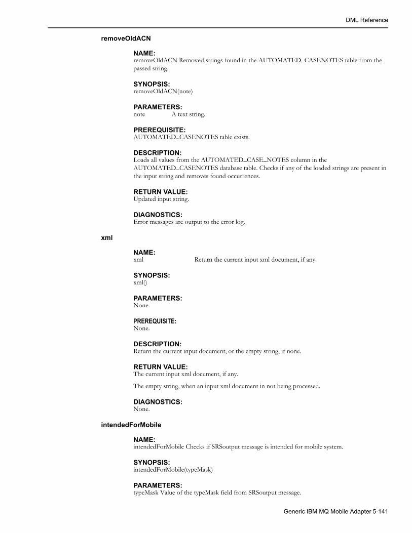
DML Reference
removeOldACN
NAME:removeOldACN Removed strings found in the AUTOMATED_CASENOTES table from the passed string.
SYNOPSIS:removeOldACN(note)
PARAMETERS:note A text string.
PREREQUISITE:AUTOMATED_CASENOTES table exists.
DESCRIPTION:Loads all values from the AUTOMATED_CASE_NOTES column in the AUTOMATED_CASENOTES database table. Checks if any of the loaded strings are present in the input string and removes found occurrences.
RETURN VALUE:Updated input string.
DIAGNOSTICS:Error messages are output to the error log.
xml
NAME:xml Return the current input xml document, if any.
SYNOPSIS:xml()
PARAMETERS:None.
PREREQUISITE:None.
DESCRIPTION:Return the current input document, or the empty string, if none.
RETURN VALUE:The current input xml document, if any.
The empty string, when an input xml document in not being processed.
DIAGNOSTICS:None.
intendedForMobile
NAME:intendedForMobile Checks if SRSoutput message is intended for mobile system.
SYNOPSIS:intendedForMobile(typeMask)
PARAMETERS:typeMask Value of the typeMask field from SRSoutput message.
Generic IBM MQ Mobile Adapter 5-141

DML Reference
PREREQUISITES:None
DESCRIPTION:Checks if SRSO_SEND_TO_MOBILE bit is set in typeMask.
RETURN VALUE:"true" is the message is intended for mobile system, otherwise empty string.
DIAGNOSTICS:Error messages are output to the error log.
EXAMPLE:intendedForMobile($E.typeMask);
getPhasesDesc
NAME:getPhasesDesc Convert bitmask representing phases into string.
SYNOPSIS:getPhasesDesc(phases)
PARAMETERS:phases Phases bitmask.
PREREQUISITES:None
DESCRIPTION:Converts phases bitmask into a string using letters A, B, C, and N to designate different phases and the neutral.
RETURN VALUE:String containing names of the phases present in the bitmask.
DIAGNOSTICS:None.
sqlQuoted
NAME:sqlQuoted Converts string into SQL text literal.
SYNOPSIS:sqlQuoted(str)
PARAMETERS:str text string.
PREREQUISITES:None
DESCRIPTION:Wraps string in single quotes and escapes single quotes in the string by replacing them with double single quotes.
RETURN VALUE:SQL text literal representation of the passed string.
5-142 Oracle Utilities Network Management System Adapters Guide
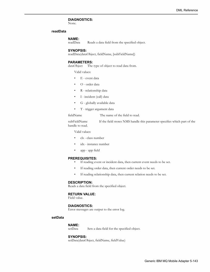
DML Reference
DIAGNOSTICS:None.
readData
NAME:readData Reads a data field from the specified object.
SYNOPSIS:readData(dataObject, fieldName, [subFieldName])
PARAMETERS:dataObject The type of object to read data from.
Valid values:
• E - event data
• O - order data
• R - relationship data
• I - incident (call) data
• G - globally available data
• T - trigger argument data
fieldName The name of the field to read.
subFieldName If the field stores NMS handle this parameter specifies which part of the handle to read.
Valid values:
• cls - class number
• idx - instance number
• app - app field
PREREQUISITES:• If reading event or incident data, then current event needs to be set.
• If reading order data, then current order needs to be set.
• If reading relationship data, then current relation needs to be set.
DESCRIPTION:Reads a data field from the specified object.
RETURN VALUE:Field value.
DIAGNOSTICS:Error messages are output to the error log.
setData
NAME:setData Sets a data field for the specified object.
SYNOPSIS:setData(dataObject, fieldName, fieldValue)
Generic IBM MQ Mobile Adapter 5-143

DML Reference
PARAMETERS:dataObject The type of object to read data from.
Valid values:
• O - order data
• R - relationship data
• G - globally available data
• T - trigger argument data
fieldName The name of the field to set.
fieldValue The value set the field to.
PREREQUISITES:• If reading order data, then current order needs to be set.
• If reading relationship data, then current relation needs to be set.
DESCRIPTION:Sets a data field for the specified object.
RETURN VALUE:Empty string.
DIAGNOSTICS:Error messages are output to the error log.
readGlobalData
NAME:readGlobalData Reads the specified globally available data field.
SYNOPSIS:readGlobalData(fieldName)
PARAMETERS:fieldName The name of the field to read.
PREREQUISITES:None.
DESCRIPTION:Reads the specified globally available data field.
RETURN VALUE:Field value.
DIAGNOSTICS:None.
setGlobalData
NAME:setGlobalData Sets the specified globally available data field.
SYNOPSIS:setGlobalData(fieldName, fieldValue)
PARAMETERS:fieldName The name of the field to set.
5-144 Oracle Utilities Network Management System Adapters Guide

DML Reference
fieldValue The value set the field to.
PREREQUISITES:None.
DESCRIPTION:Sets the specified globally available data field.
RETURN VALUE:Empty string.
DIAGNOSTICS:None.
eraseGlobalData
NAME:eraseGlobalData Erases the specified globally available data field.
SYNOPSIS:eraseGlobalData(fieldName)
PARAMETERS:fieldName The name of the field to erase.
PREREQUISITES:None.
DESCRIPTION:Erases the specified globally available data field.
RETURN VALUE:Empty string.
DIAGNOSTICS:None.
readOrderField
NAME:readOrderField Finds an order and reads a field from it.
SYNOPSIS:readOrderField(lookupFieldName, lookupFieldValue, orderFieldName)
PARAMETERS:lookupFieldName The name of the lookup field.
lookupFieldValue The value of the lookup field to search for.
orderFieldName The name of the field to read.
PREREQUISITES:None.
DESCRIPTION:Finds an order with the specified lookup field set to the desired value and reads the specified order field.
RETURN VALUE:Field value. Empty string if order was not found.
Generic IBM MQ Mobile Adapter 5-145
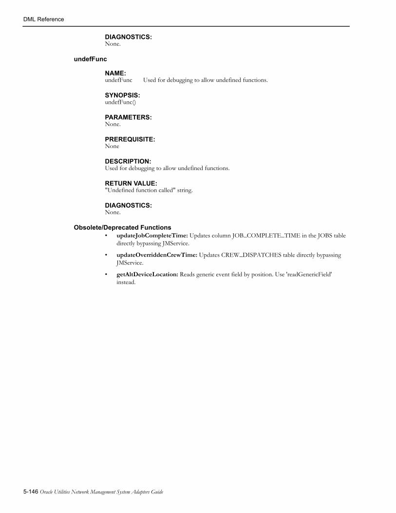
DML Reference
DIAGNOSTICS:None.
undefFunc
NAME:undefFunc Used for debugging to allow undefined functions.
SYNOPSIS:undefFunc()
PARAMETERS:None.
PREREQUISITE:None
DESCRIPTION:Used for debugging to allow undefined functions.
RETURN VALUE:"Undefined function called" string.
DIAGNOSTICS:None.
Obsolete/Deprecated Functions• updateJobCompleteTime: Updates column JOB_COMPLETE_TIME in the JOBS table
directly bypassing JMService.
• updateOverriddenCrewTime: Updates CREW_DISPATCHES table directly bypassing JMService.
• getAltDeviceLocation: Reads generic event field by position. Use 'readGenericField' instead.
5-146 Oracle Utilities Network Management System Adapters Guide

Event Object Fields
Event Object FieldsThese are the fields available in the external event object ‘E’. For each field the equivalent SRSoutput data field is listed.
Field Name SRSoutput Data Fields
alarmHdl SRSoutput::alarmHdl
devHdl SRSoutput::devHdl
feederHdl SRSoutput::feederHdl
outageHdl SRSoutput::outageHdl
oldEvent SRSoutput::oldEvent
condHdl SRSoutput::condHdl
extraDevHdl SRSoutput::extraDevHdl
devClsName SRSoutput::devClsName
incidentType SRSoutput::incidentType
description SRSoutput::description
cause SRSoutput::cause
preferredAlias SRSoutput::perferredAlias
troubleCode SRSoutput::troubleCode
troubleQueue SRSoutput::troubleQueue
office SRSoutput::office
circuit SRSoutput::circuit
district SRSoutput::district
dispAddress SRSoutput::dispAddress
addrBuilding SRSoutput::addrBuilding
addrStreet SRSoutput::addrStreet
addrCity SRSoutput::addrCity
city SRSoutput::city
status SRSoutput::status
feeder SRSoutput::feeder
tags SRSoutput::tags
est_source SRSoutput::est_source
comment SRSoutput::comment
devCode SRSoutput::devCode
externId SRSoutput::externId
Generic IBM MQ Mobile Adapter 5-147

Event Object Fields
crewId SRSoutput::crewId
supplyNodeDevice SRSoutput::supplyNodeDevice
supplyNodeIndexes SRSoutput::supplyNodeIndexes
leafNcgs SRSoutput::leafNcgs
numLeafNcgs SRSoutput::numLeafNcgs
actionIDs SRSoutput::actionIDs
numActionsIDs SRSoutput::numActionsIDs
outageTime SRSoutput::outageTime
firstIncTime SRSoutput::firstIncTime
firstIncTimeStr SRSoutput::firstIncTimeStr
estRestTime SRSoutput::estRestTime
estRestTimeStr SRSoutput::estRestTimeStr
estAssessTime SRSoutput::estAssessTime
complete_time SRSoutput::complete_time
job_complete_time SRSoutput::job_complete_time
msgType SRSoutput::msgType
validStateKey SRSoutput::validStateKey
prevStateKey SRSoutput::prevStateKey
stateValue SRSoutput::stateValue
condStatus SRSoutput::condStatus
condPhases SRSoutput::condPhases
customersOut SRSoutput::customersOut
typeMask SRSoutput::typeMask
partition SRSoutput::partition
ncg SRSoutput::ncg
appliedRule SRSoutput::appliedRule
priority SRSoutput::priority
custCall SRSoutput::custCall
pri_w SRSoutput::pri_w
pri_sw SRSoutput::pri_sw
pri_p SRSoutput::pri_p
pri_e SRSoutput::pri_e
custCrit SRSoutput::custCrit
Field Name SRSoutput Data Fields
5-148 Oracle Utilities Network Management System Adapters Guide

Event Object Fields
crit_1 SRSoutput::crit_1
crit_2 SRSoutput::crit_2
crit_3 SRSoutput::crit_3
crit_tot SRSoutput::crit_tot
revenue SRSoutput::revenue
numSndDev SRSoutput:: numSndDev
numSupplied SRSoutput::numSupplied
outageRef SRSoutput::outageRef
oldCondID SRSoutput::oldCondID
sort_col_1 SRSoutput::sort_col_1
sort_col_2 SRSoutput::sort_col_2
sort_col_3 SRSoutput::sort_col_3
sort_col_4 SRSoutput::sort_col_4
sort_col_5 SRSoutput::sort_col_5
sort_col_6 SRSoutput::sort_col_6
sort_col_7 SRSoutput::sort_col_7
sort_col_8 SRSoutput::sort_col_8
sort_col_9 SRSoutput::sort_col_9
life_support SRSoutput::life_support
outage_type SRSoutput::outage_type
old_outage_type SRSoutput::old_outage_type
group_type SRSoutput::group_type
messages SRSoutput::messages
customer_phone SRSoutput::customer_phone
numb SRSoutput::numb
inc_outage SRSoutput::inc_outage
devAlias SRSoutput::devAlias
customerName SRSoutput::customerName
rule_set SRSoutput::rule_set
crit_k SRSoutput::crit_k
crit_c SRSoutput::crit_c
crit_d SRSoutput::crit_d
from_str SRSoutput::from_str
Field Name SRSoutput Data Fields
Generic IBM MQ Mobile Adapter 5-149

Event Object Fields
mergedEvents SRSoutput::mergedEvent
numMerged SRSoutput::numMerged
hasClue SRSoutput::hasClue
ctrlZoneHdl1 SRSoutput::ctrlZoneHdl1
ctrlZoneHdl2 SRSoutput::ctrlZoneHdl2
ctrlZoneHdl3 SRSoutput::ctrlZoneHdl3
ctrlZoneHdl4 SRSoutput::ctrlZoneHdl4
ctrlZoneHdl5 SRSoutput::ctrlZoneHdl5
ctrlZoneHdl6 SRSoutput::ctrlZoneHdl6
ctrlZoneName1 SRSoutput::ctrlZoneName1
ctrlZoneName2 SRSoutput::ctrlZoneName2
ctrlZoneName3 SRSoutput::ctrlZoneName3
ctrlZoneName4 SRSoutput::ctrlZoneName4
ctrlZoneName5 SRSoutput::ctrlZoneName5
ctrlZoneName6 SRSoutput::ctrlZoneName6
who_responsible SRSoutput::who_responsible
who_completed SRSoutput::who_completed
resp_modify_time SRSoutput:: resp_modify_time
xRef SRSoutput::xRef
yRef SRSoutput::yRef
highestIncPri SRSoutput::highestIncPri
referralGroup SRSoutput::referralGroup
who SRSoutput::who
firstCrewTime SRSoutput::firstCrewTime
additionalDevHdls SRSoutput::additionalDevHdls
additionalCondHdls SRSoutput::additionalCondHdls
relatedEvents SRSoutput::relatedEvents
additionalCondStatuses SRSoutput::additionalCondStatuses
numAdditional SRSoutput::numAdditional
numRelated SRSoutput::numRelated
maxNum SRSoutput::maxNum
maxNumRelated SRSoutput::maxNumRelated
routeId SRSoutput::routeId
Field Name SRSoutput Data Fields
5-150 Oracle Utilities Network Management System Adapters Guide

Event Object Fields
Incident Object FieldsThese are the fields available in the external incident object ‘I’ and for sorting incidents. For each field the equivalent Incident data access function is listed.
repair_minutes SRSoutput::repair_minutes
crew_eta SRSoutput::crew_eta
sheetNums SRSoutput::sheetNums
generic_col_1 SRSoutput::generic_col_1
related_event SRSoutput::related_event
related_type SRSoutput::related_type
Field Name SRSoutput Data Fields
Incident Field Name Function Call
getGroupingFlag Incident::getGroupingFlag()
getMessages Incident::getMessages()
getClosestMeshNode Incident::getClosestMeshNode()
getHdl Incident::getHdl()
getSnd Incident::getSnd()
getCondHdl Incident::getCondHdl()
getPartition Incident::getPartition()
getPhases Incident::getPhases()
getCondStatus Incident::getCondStatus()
getEvent Incident::getEvent()
getPriority Incident::getPriority()
getType Incident::getType()
getClue Incident::getClue()
getBitmask Incident::getBitmask()
getTotalPriority Incident::TotalPriority()
getLifeSupportCode Incident::getLifeSupportCode()
getCriticalCustomer Incident::getCriticalCustomer()
getCallCancelInd Incident::getCallCancelInd()
getCallbackLateInd Incident::getCallbackLateInd()
getTcode Incident::getTcode() (This maps to INCIDENTS.COMPLAINT.)
Generic IBM MQ Mobile Adapter 5-151

Event Object Fields
getTroubleQueue Incident::getTroubleQueue()
getShortDesc Incident::getShortDesc()
getDrvInst Incident::getDrvInst()
getCID Incident::getCID()
getCustomerName Incident::getCustomerName()
getCtype Incident::getCtype()(This maps to INCIDENTS.CUSTOMER_TYPE.)
getAddrBuilding Incident::getAddrBuilding()
getAddrStreet Incident::getAddrStreet()
getAddrCity Incident::getAddrCity()
getOrderNumber Incident::getOrderNumber()
getGenernalArea Incident::getGeneralArea()
getMeterId Incident::getMeterId()
getDeviceAlias Incident::getDeviceAlias()
getNcg Incident::getNcg()
getExternalId Incident::getExternalId()
getInputTime Incident::getInputTime()
getCallbackRequest Incident::getCallbackRequest()
getCallbackDataTime Incident::getCallbackDataTime()
getOpComment Incident::getOpComment()
getCustomerPhone Incident::getCustomerPhone()
alternatePhone Incident::alternatePhone()
userName Incident::userName()
getXRef Incident::getXRef()
getYRef Incident::getYRef()
getExternallySent Incident::getExternallySent()
getAONFlag Incident::getAONFlag()
getROCFlag Incident::getROCFlag()
active Incident::active()
Incident Field Name Function Call
5-152 Oracle Utilities Network Management System Adapters Guide
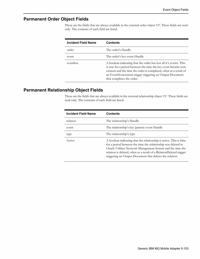
Event Object Fields
Permanent Order Object FieldsThese are the fields that are always available in the external order object ‘O’. These fields are read-only. The contents of each field are listed.
Permanent Relationship Object FieldsThese are the fields that are always available in the external relationship object ‘O’. These fields are read-only. The contents of each field are listed.
Incident Field Name Contents
order The order’s Handle
event The order’s key event Handle
eventless A boolean indicating that the order has lost all it’s events. This is true for a period between the time the key event became non-existent and the time the order is completed, often as a result of an EventNonexistent trigger triggering an Output Document that completes the order.
Incident Field Name Contents
relation The relationship’s Handle
event The relationship’s key (parent) event Handle
type The relationship’s type
Active A boolean indicating that the relationship is active. This is false for a period between the time the relationship was deleted in Oracle Utilities Network Management System and the time the relation is deleted, often as a result of a RelationDeleted trigger triggering an Output Document that deletes the relation.
Generic IBM MQ Mobile Adapter 5-153

Event Object Fields
5-154 Oracle Utilities Network Management System Adapters Guide

Chapter 6SCADA Measurements
This chapter includes the following topics:
• Introduction to scadapop
• Configuration
• Recaching Measurements
• Information Model
Introduction to scadapopThe Oracle Utilities Network Management System (NMS) can accept updates from a variety of external (outside) Supervisory Control And Data Acquisition (SCADA) systems. Multiple external SCADA systems can be connected to a single NMS instance. If necessary a different adapter can be used for each external SCADA a utility wishes to connect to. For example one SCADA system might use the ICCPAdapter, one the generic NMS SCADA adapter (RTAdapter) another might use a project specific or custom SCADA adapter. In all cases the NMS objects and attributes that can be updated from each external SCADA adapter must be defined before NMS can accept input from these SCADA systems. This section describes one mechanism for populating the necessary configuration tables with objects and attribute information so the SCADA adapter can pass information into NMS.
Configuration
RDBMS Configuration
Tables involved:
• scada_measurements_st: standard SCADA measurements configuration table. This is a staging table used by DDService for populating the production SCADA measurement tables.
• digital_measurements: production SCADA measurements table for digital measurements. Only DDService should write to this table.
• analog_measurements: production SCADA measurements table for analog measurements. Only DDService should write to this table.
• scada_ids: SCADA definition table.
• scada_points: optional model build attribute table that is used by the scadapop executable - to help populate the scada_measurements_st staging table. If you want to use scadapop – you need to populate the scada_points table.
SCADA Measurements 6-1
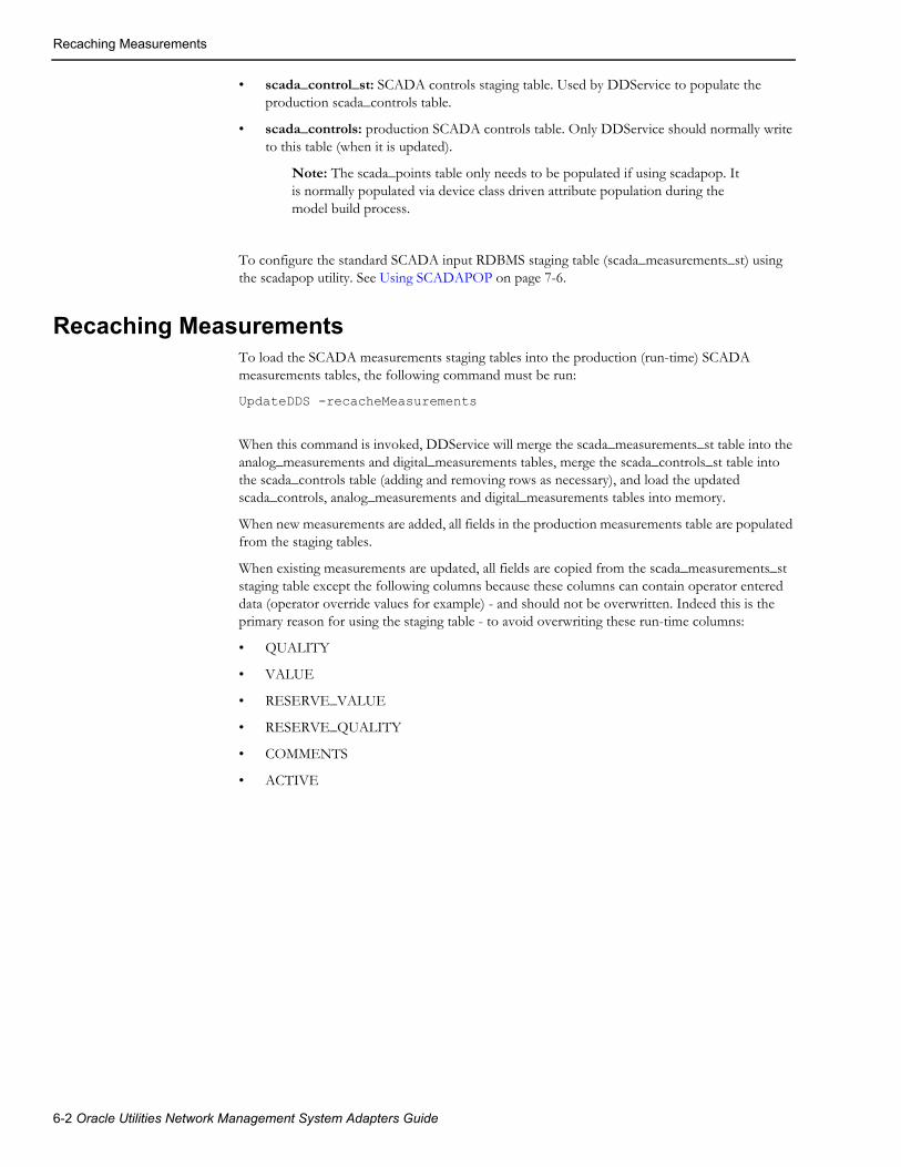
Recaching Measurements
• scada_control_st: SCADA controls staging table. Used by DDService to populate the production scada_controls table.
• scada_controls: production SCADA controls table. Only DDService should normally write to this table (when it is updated).
Note: The scada_points table only needs to be populated if using scadapop. It is normally populated via device class driven attribute population during the model build process.
To configure the standard SCADA input RDBMS staging table (scada_measurements_st) using the scadapop utility. See Using SCADAPOP on page 7-6.
Recaching MeasurementsTo load the SCADA measurements staging tables into the production (run-time) SCADA measurements tables, the following command must be run:
UpdateDDS -recacheMeasurements
When this command is invoked, DDService will merge the scada_measurements_st table into the analog_measurements and digital_measurements tables, merge the scada_controls_st table into the scada_controls table (adding and removing rows as necessary), and load the updated scada_controls, analog_measurements and digital_measurements tables into memory.
When new measurements are added, all fields in the production measurements table are populated from the staging tables.
When existing measurements are updated, all fields are copied from the scada_measurements_st staging table except the following columns because these columns can contain operator entered data (operator override values for example) - and should not be overwritten. Indeed this is the primary reason for using the staging table - to avoid overwriting these run-time columns:
• QUALITY
• VALUE
• RESERVE_VALUE
• RESERVE_QUALITY
• COMMENTS
• ACTIVE
6-2 Oracle Utilities Network Management System Adapters Guide

Information Model
Information Model
Database Schema
SCADA_IDS Database TableThe schema for this table is defined in ces_schema_scada.sql file.
The script, OPAL_scada_ids.sql, populates generic SCADA sources for the OPAL model. A source is any SCADA system that can provide information to the adapter. There could be one SCADA source defined for each of multiple SCADA vendors, or a utility may choose to divide their territory into multiple regions, with each region acting as a separate SCADA source. Each SCADA source must have a unique name as well as a unique integer ID.
SCADA_IDS
SCADA_POINTS Database TableThe SCADA_POINTS table contains a row for each device in the Oracle Utilities Network Management System operations database that has SCADA information associated with it. Each record has a “scada_name” column which, in order to populate one of the measurements tables, must match a valid "scadapop -scada <scada>" parameter - where <scada> is a valid and active scada_ids.scada_name value. Where there is a match, a row is populated in the scada_measurements_st table for each defined attribute.
The SCADA_POINTS table is normally populated via device driven attribute population during the model build process. It is a staging table for the scadapop-driven measurement point population process. It is not accessed during adapter execution.
The schema for this table can be found in the file ces_retain_scada.sql
Column Data Type Description
ID NUMBER Numeric identifier for each “SCADA source” that we want RTI to process.
SCADA_NAME VARCHAR2(32) Name for the SCADA source
ADAPTER_TYPE VARCHAR2(32) Adapter type for this SCADA source.
ACTIVE VARCHAR2(1) Is the adapter active (Y/N)
SCADA Measurements 6-3
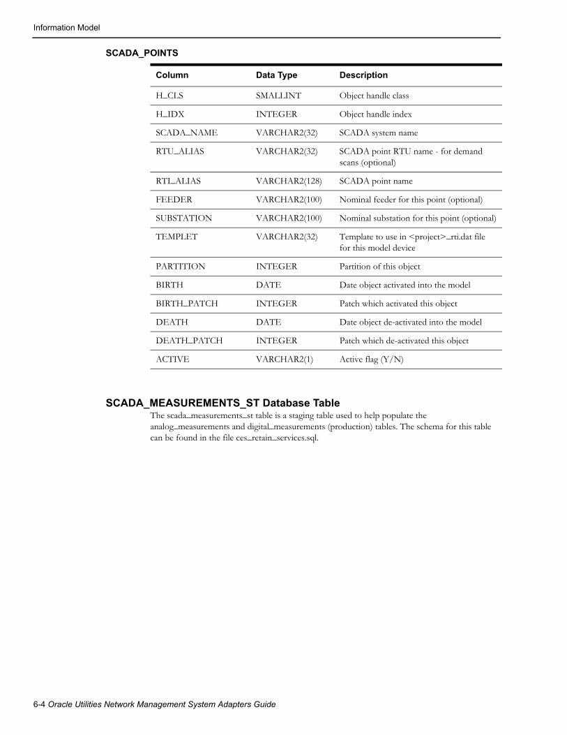
Information Model
SCADA_POINTS
SCADA_MEASUREMENTS_ST Database TableThe scada_measurements_st table is a staging table used to help populate the analog_measurements and digital_measurements (production) tables. The schema for this table can be found in the file ces_retain_services.sql.
Column Data Type Description
H_CLS SMALLINT Object handle class
H_IDX INTEGER Object handle index
SCADA_NAME VARCHAR2(32) SCADA system name
RTU_ALIAS VARCHAR2(32) SCADA point RTU name - for demand scans (optional)
RTI_ALIAS VARCHAR2(128) SCADA point name
FEEDER VARCHAR2(100) Nominal feeder for this point (optional)
SUBSTATION VARCHAR2(100) Nominal substation for this point (optional)
TEMPLET VARCHAR2(32) Template to use in <project>_rti.dat file for this model device
PARTITION INTEGER Partition of this object
BIRTH DATE Date object activated into the model
BIRTH_PATCH INTEGER Patch which activated this object
DEATH DATE Date object de-activated into the model
DEATH_PATCH INTEGER Patch which de-activated this object
ACTIVE VARCHAR2(1) Active flag (Y/N)
6-4 Oracle Utilities Network Management System Adapters Guide

Information Model
SCADA_MEASUREMENTS_ST
Column Data Type Description
H_CLS SMALLINT Object handle class
H_IDX INTEGER Object handle index
PARTITION INTEGER Object partition
ATTRIBUTE SMALLINT Data attribute index (from ATTRIBUTES table)
TTL SMALLINT Time-To-Live Value
LIMIT_GROUP_ID INTEGER Object limit group
RTI_ALIAS VARCHAR2(128) RTI device measurement name
RTI_ALIAS_A VARCHAR2(128) RTI device measurement name for phase A. Only applies for digital measurements and only used by the MultiSpeak SCADA adapter.
RTI_ALIAS_B VARCHAR2(128) RTI device measurement name for phase B. Only applies for digital measurements and only used by the MultiSpeak SCADA adapter.
RTI_ALIAS_C VARCHAR2(128) RTI device measurement name for phase C. Only applies for digital measurements and only used by the MultiSpeak SCADA adapter.
SCADA_ID INTEGER SCADA source identifier - matches scada_ids.id
RTU_ID VARCHAR2(32) RTU ID - unique name within SCADA system.
QUALITY INTEGER Quality code
VALUE FLOAT Manual Replace Value
UPDATE_FLAG INTEGER Manual Replace Flag
ICCP_OBJECT VARCHAR2(32) ICCP mms object name
DISPLAY_ID VARCHAR2(64) ID for display call up
CONTROLLABLE VARCHAR2(1) Is this row controllable
ACTIVE VARCHAR2(1) Is this row active
SOURCE VARCHAR2(33) Source of measurements
COMMENTS VARCHAR2(512) Comment associated with
OFF_NOMINAL_TIME
DATE Time quality went off-nominal
NORMAL_STATE INTEGER Normal state for measure. Only used for digital measurements.
SCADA Measurements 6-5
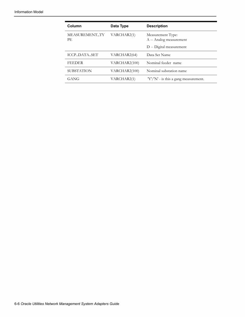
Information Model
MEASUREMENT_TYPE
VARCHAR2(1) Measurement Type:A -- Analog measurement
D -- Digital measurement
ICCP_DATA_SET VARCHAR2(64) Data Set Name
FEEDER VARCHAR2(100) Nominal feeder name
SUBSTATION VARCHAR2(100) Nominal substation name
GANG VARCHAR2(1) 'Y'/'N' - is this a gang measurement.
Column Data Type Description
6-6 Oracle Utilities Network Management System Adapters Guide

Chapter 7Generic SCADA Adapter
This chapter includes the following topics:
• Introduction
• Generic SCADA Adapter Configuration
• Measurement Configuration
• RDBMS Configuration
• Configuration/Execution Sequence
• Information Model
• MultiSpeak Integration
• DataRaker Integration
IntroductionThe Generic SCADA Adapter (executable name: RTAdapter) is an Oracle Utilities Network Man-agement System adapter that can process incoming analogs, digitals and conditions from an exter-nal SCADA system. The RTAdapter can also send field device control requests and condition updates from the Network Management System to an external SCADA system.
This section is used to guide the user in the configuration of the Oracle Utilities Network Manage-ment System Generic SCADA Adapter. It is assumed that the Oracle Utilities Network Manage-ment System is installed and functional.
Generic SCADA Adapter 7-1
Generic SCADA Adapter Configuration
Generic SCADA Adapter Configuration
RDBMS vs. File Mode
Each Generic SCADA Adapter instance can process input from either Network Management Sys-tem RDBMS queuing tables (preferred) or from flat files, but not both. A Network Management System can support multiple file-based RTAdapter instances, but only one RTDBAdapter (config-ured for RDBMS input).
RDBMS mode: The external SCADA system writes SCADA updates to a set of RDBMS queu-ing tables. Updates are processed by RTAdapter on a first-in-first-out basis.
File mode: Each external SCADA system writes SCADA “scan files” to a dedicated directory that an appropriately configured RTAdapter can access in read/write mode. Incoming “scan files” are processed on a first-in-first-out basis.
Configure Adapter to Run as an NMS System Service
Configure the Generic SCADA Adapter to run as an Oracle Utilities Network Management Sys-tem service by updating the $NMS_HOME/etc/system.dat file to include the Generic SCADA Adapter as a system service. There are three main sections of the system.dat file where a service needs to be defined: the service, program, and instance sections.
See the $CES_HOME/templates/system.dat.template file for examples of how to configure the Generic SCADA Adapter. Search for RTAdapter in the file and copy those lines to $NMS_HOME/etc/system.dat file. Make sure all lines are uncommented so SMService will find them as active. You must either restart SMService or start SMService with a “-f ~/etc/system.dat” command line option to pick up changes to the $NMS_HOME/etc/system.dat configuration file.
Notes: The adapter process is often given a configuration name adapted from the SCADA system from which it is receiving data. Reference the RTDBAdapter configuration option in the $CES_HOME/templates/system.dat.template for an example of this type of configuration. The first parameter after the keyword program must match the -process_name parameter. The -scada option specifies the name of the SCADA for this instance of the RTAdapter (from the SCADA_IDS table) and often matches the -process_name option (though this is not required).
7-2 Oracle Utilities Network Management System Adapters Guide

Generic SCADA Adapter Configuration
SRS_RULES Configuration for Generic SCADA AdapterThe Generic SCADA Adapter currently supports a few options that can only be configured via the Network Management System SRS_RULES mechanism. The Configuration Assistant tool provides rule specific details on what impact these SRS_RULES have on how the Generic SCADA Adapter responds to various forms of input. The adapter reloads SRS_RULES configuration when Service Recache button is clicked in Configuration Assistant.
Note: Only the rule names are listed here; use the Oracle Utilities Network Management System Configuration Assistant’s Event Management Rules tab for details and to update the rules, if necessary.
• RT_PLANNED_OUTAGE_QUALITY
• RT_STALE_PROCESSING_CYCLE
• RT_CALCULATED_POINTS
• RT_CALCULATED_POINT
• RT_CONDITIONS_IN
• RT_CONDITIONS_OUT
Command Line Options for Generic SCADA Adapter
The command line for the Generic SCADA Adapter provides the following options:
Command Line Option What it does
-cert_file <full path to certificate>
The private certificate used for incoming device/screen navigation messages from the SCADA system. This is the server's private key concatenated with its certificate, as used by GSOAP.
-client_cert Whether to require public certificates for incoming screen navigation messages from the SCADA system. This is the client key concatenated with the certificate.
-controls <script name> Tells RTAdapter to call this project/SCADA specific script when an NMS outbound control requests (digital open/close or analog set point control) are made. This script is typically customized to trigger a SCADA specific action on the external system. Note: this option MUST be set for RTAdapter to do any processing of outbound control requests.
-debug Enable debugging. Other common facility specific debug options are also possible. Common options include:-debug RT_NFY 1 # debug for notify messages-debug RT_CALC 1 # debug for calculated points-debug RT_CTRL 1 # debug for control msg processing-debug RT_PROC 1 # debug for outage processing-debug RT_WATCH 1 # debug to track high-level activity-debug RT_COND # debug for condition processing-debug RT_STALE 1 # debug for stale processing
Generic SCADA Adapter 7-3

Generic SCADA Adapter Configuration
-delimiter <char> Allows a project to override the default input delimiter character (|) with the specified character.Used for file based input and, potentially, for setting multiple external quality code strings, which must be mapped back to integers internally, via RDBMS-based input.
-dir <directory> For file based input this is the directory containing scada data export scan files.For RDBMS based input this must be set to ‘RDBMS’. (Required)
-idle <cycles> Number of processing cycles to wait without processing any data before sending an alarm.
-interval <interval> Seconds between processing (polling) cycles.(Required)
-lock Use file locking to prevent file overwrite during file read (if scan file names are not unique). File based input only.
-no_analogs Do not scan the scada_analog_in table or process analogs.
-noStaleProcessing Do not generate stale quality codes. This is useful primarily in testing and training environments when you have two instances of the adapter configured to use the same SCADA points, and you do not want them to both generate conflicting stale quality flags.
-offline For testing purposes - when a control request is received - simulate the external SCADA system and operate the device.
-offlineDelay <seconds> Seconds between receiving a CONTROL request (in offline mode) and responding. Used to help simulate an actual SCADA system.
-operate Operate (change status of) model devices, otherwise generates pseudo alarms only.
-process_name <name> Network Management System message bus process name for this process. If the first parameter after the keyword program in the first column of the system.dat file is something other than the second parameter - then you must set the -process_name option to the same string as the first parameter. This is only necessary if you need to run more than one instance of RTAdapter or you want RTAdapter to be known as some other name within the Network Management System messaging bus. Network Management Process message bus process names must be unique.
-retain For RDBMS input only. Retain data in the scada_digital_in and scada_condition_in tables after data is processed. Generally for validation/debug - not general purpose production use or long term logging.
-scada <scada> External SCADA name. (Required). Must match an active SCADA entry in the scada_ids table (scada_ids.scada_name).
Command Line Option What it does
7-4 Oracle Utilities Network Management System Adapters Guide

Generic SCADA Adapter Configuration
Scripts Used by the Generic SCADA Adapter
The Generic SCADA Adapter calls various scripts to communicate and coordinate with an exter-nal SCADA system. Example scripts are provided. The example scripts use curl and expect the external SCADA systems will support some form of RESTful Web Service integration. You can create project-specific versions/variations of these scripts that are appropriate for a specific SCADA system.
CES_PARAMETERS ConfigurationThe adapter needs to be restarted for CES_PARAMETERS configuration changes to take effect.
-watch <level> Show data being processed, minimal info. <level> is an integer that maps to the RT_WATCH debug facility.
Command Line Option What it does
Script Description
rti_notify_start.ces Notifies the SCADA system that the Generic SCADA Adapter has restarted. Call from RTAdapter on restart.
rti_operate.ces Example script for use with the RTAdapter controls option (e.g., -controls rti_operate.ces). This script can either forward to SCADA or simulate a SCADA positive response when device control requests are sent from NMS.
scada_reload.ces Notifies the SCADA system that the set of measurements has changed due to an NMS model build.
rti_operate_curl.ces Another example script for use with the RTAdapter controls option. Sends the control request to the SCADA system as a RESTful web-service request via curl.
Parameter Description
SCADA_URL Used to identify the external SCADA. RTAdapter will send navigation and SCADA controls to the SCADA system via this URL. The SCADA_URL should be the root URL. The scripts will add instruct, reload, navigate, etc. to the URL as needed.
SCADA_CERT The certificate to connect to the SCADA system. This is the client piece of a certificate generated by the SCADA system.
Generic SCADA Adapter 7-5

Measurement Configuration
Measurement ConfigurationThe Generic SCADA Adapter comes with a configuration support tool (scadapop) that can be used to help populate the standard SCADA configuration (scada_measurements_st) table used for incoming SCADA data and the outbound SCADA controls (scada_controls_st) table.
Using SCADAPOPThe scadapop executable uses the <project>_rti.dat parameter file to help define what SCADA measurements and controls are desired for each class of object in the NMS model. The scadapop process reads the scada_points table to determine which instance of each class of data SCADA configuration is desired for. The scadapop process merges the instance information in the scada_points table with the class definition information in the <project>_rti.dat configuration file to perform the desired SCADA configuration.
The scadapop mechanism makes the assumption that each instance of a given device class in the NMS generally contains the same set of NMS SCADA measurement types.
For cases where more or less actual SCADA measurements are available for a given class of device than "normal" there are two approaches that can be used. The first (and likely preferred) approach is an exception based mechanism that is trigged by populating the SCADA_POINTS.TEMPLET field. If the SCADA_POINTS.TEMPLET field is populated scadapop will treat the TEMPLET field like any other CLASS definition in the <project>_rti.dat file and use it instead of any associated CLASS definition. The second approach is simply the understanding that NMS measurements do not have to have a match in SCADA - though that is obviously preferred. If no corresponding SCADA measurement exists the field will just never be populated.
Note that the CLASS: and TEMPLET: definitions within the <project>_rti.dat file share the same name space so care must be taken to make sure the definitions do NOT overlap. For example, TEMPLET: definitions could always start with "t_" to signify it was a TEMPLET and minimize the possibility of overlapping with CLASS: definitions.
An example <project>_rti.dat template can normally be found on an active NMS environment under $CES_HOME/templates/rti.dat.template.
The syntax for the <project>_rti.dat file content is as follows.
• Primary (initial) keyword tokens:
• CONTROL:
• CLASS:
• TEMPLET:
• Secondary keyword tokens (dependent on a primary keyword):
• NMS_ACTION: dependent on previous CONTROL:
• Analog: dependent on previous CLASS: or TEMPLET:
• Digital: dependent on previous CLASS: or TEMPLET:
• Keyword parameters:
• CONTROL: <unique string>
• unique name for a set of SCADA controls – starts with alpha character.
• CLASS: <NMS class name>
• can be an abstract class – for use with inheritance
• TEMPLET: <template name>
• must be unique among all CLASS: and TEMPLET: definitions.
7-6 Oracle Utilities Network Management System Adapters Guide

Measurement Configuration
• Analog: <NMS analog attribute name> [CTRL_tag]
• NMS analog attribute name must be a valid NMS analog attribute name
• CTRL_tag must match a previous CONTROL: definition
• Only valid below a CLASS: or TEMPLET: definition
• Digital: <NMS digital attribute name> [CTRL_tag] [Nominal]
• NMS digital attribute name must be a valid NMS digital attribute name
• CTRL_tag must match a previous CONTROL: definition
• Nominal, if specified, should be 1 as default is 0 and only 0/1 allowed.
• Only valid below a CLASS: or TEMPLET: definition
The following three keywords are in reference to a single valid scada_controls_st entry and are comma (,) separated on the same line. They are cumulatively associated with the previous “CONTROL:” block.
NMS_ACTION: <integer> - NMS integer for this actionEXT_ACTION: <integer> - external (SCADA) integer for this actionTIMEOUT: <integer> - number of seconds to wait for feedback.
Notes on keywords/values:
• The nominal value for the special NMS digital “Status(0)” attribute is maintained via the NMS model build process in network_components.nominal_status field and cannot be specified via this mechanism – as Status is a 3-phase digital representation with values from 0->7.
• If the scada_points.templet field matches a specified TEMPLET: definition than this TEMPLET will take priority over any other (CLASS: based) processing.
• If the scada_points.h_cls field matches or inherits from the specified CLASS: then the associated, Analog:, Digital: and (optionally) CONTROL: configuration will be applied. This is inheritance based processing.
• The colon (:) character is a keyword delimiter. The colon must appear as the first character after the keyword in order for the keyword to be recognized.
• Keywords must match exactly.
• Lines with a leading # are treated as comments (ignored).
• Leading blank space is ignored.
• Blank lines are ignored.
• Attributes are associated to last defined CLASS: or TEMPLET: statement.
Generic SCADA Adapter 7-7

Measurement Configuration
Example <project>_rti.dat Configuration
CONTROL: CTRL_setpoint NMS_ACTION:100,EXT_ACTION:10,TIMEOUT:40
CONTROL: CTRL_switch NMS_ACTION:1,EXT_ACTION:0,TIMEOUT:40 NMS_ACTION:2,EXT_ACTION:1,TIMEOUT:40
CLASS: _scada_switch Digital: Status CTRL_switch Digital: AutoReclose CTRL_switch 1 Digital: door 1 Analog: Amps_A Analog: Amps_B Analog: Amps_C
CLASS: _voltage_reg Analog: reg_setpoint CTRL_setpoint
TEMPLET: t_bellwetherAnalog: Volts
To configure the standard SCADA measurement staging tables (scada_measurements_st and optional scada_controls_st) using scadapop, follow steps similar to the following:
Specify which devices have SCADA (via scada_points table):
1. The scada_points table can be populated via standard attribute population during model build construction/update or it can be populated after the model is built/updated by a custom (project specific) process.
2. Populate scada_points RDBMS table via model build device attribute configuration.
To set up the scada_points table as a standard Network Management System attribute table generally involves the following RDBMS tables:
• device_attributes: standard model build attribute configuration.
• scada_points: SCADA specific attribute table.
This option involves populating at least four attributes in the scada_points attribute table:
1. scada_name: Name of SCADA, as defined in scada_ids.scada_name (for example, RTAdapter)
2. rtu_alias: Unique identifier for reporting field device (not attribute) for this SCADA.
3. substation: Nominal substation for the device (optional).
4. feeder: Nominal feeder for the device (optional).
5. rti_alias
Once the scada_points table is populated, the scadapop program can be used to expand the information in the scada_points attribute table to fully populate the more generic scada_measurements_st and scada_controls_st staging tables.
Note: A given field device corresponds to a given scada_points.rti_alias and would typically be a switch of some kind often reporting both digital status and multiple analog values, for example. It could also be a transformer reporting analog values with or without status.
7-8 Oracle Utilities Network Management System Adapters Guide

Measurement Configuration
Review the example Network Management System OPAL device_attributes configuration file as an example of how to configure the NMS model build process to populate the scada_points table for use with scadapop. For more information on the model build process, see the Network Management System Model Build process documentation.
Once the scada_points table is populated, the scadapop program can be used to expand this information to fully populate the scada_measurements_st staging tables and (optionally) the scada_controls_st table.
Run scadapop -h to get command line options. In general:
scadapop [-debug [n]] -partition <n> -initFile <file> [-nonUniq||-attrName] –scada <scada> [-controls]
[-separator <c>] [-warnings]
-debug <n> Turns debug on <to level n>
-partition <n> Populate partition n (0 = all partitions)
-initFile <file> Initialization file (<project>_rti.dat)
-scada <scada> Specific SCADA to process (scada_ids.scada_name)
-nonUniq Do not append attribute to rti_alias (legacy support)
-attrName Append attribute name (rather than attribute number) for unique measurements.
-controls Populate scada_controls_st table
-separator <c> Use <c> as the character between the device name and attribute
-warnings Turn on data warnings. By default only errors are displayed.
The <project>_rti.dat file is the configuration file used by the scadapop program. Based on data in this file, model information (gang operable or not) and entries in the scada_points table, scadapop populates the scada_measurements_st staging table and (optionally) the scada_controls_st table.
The scada_points table should contain a single record (row) for each device in the Network Management System model that has SCADA measurements (attributes) associated with it. Each active scada_points.rti_alias value must be unique since this is the basis for scada measurement names that scadapop will generate. Each record has a “scada_name” column which, in order to populate the scada_measurements_st staging table, must match the scadapop -scada <scada> value.
By default scadapop will append a dash “-” followed by the NMS attribute number to each rti_alias - other than for attribute=0 (status) where nothing will be appended. The -attrName option will similarly append the dash and the NMS attribute name to each rti_alias - except where attribute=0. If the “-separator <c>” option is used, the specified <c> character will be used instead of the default dash separator for the same purpose.
Generic SCADA Adapter 7-9

Measurement Configuration
Examples of scadapop command line execution:
1. scadapop -partition 0 -initFile ${CES_DATA_FILES}/OPAL_rti.dat -scada <mySCADA> -separator ^ -attrName
This example will populate the scada_measurements_st for all partitions for the SCADA named mySCADA in scada_ids.scada_name. It will use the caret symbol (^) separator and will append attribute names (not numbers) to each device to construct unique measurement names.
2. scadapop -partition 3111 -initFile rti.dat -scada <mySCADA> -attrName
This example will populate the scada_measurements_st for partition 3111 for the SCADA named mySCADA. It will also append a dash (-) and the name of each NMS attribute to the base scada_points.rtu_name.
7-10 Oracle Utilities Network Management System Adapters Guide

RDBMS Configuration
RDBMS ConfigurationThe Network Management System Generic SCADA Adapter (RTAdapter) utilizes several RDBMS tables for both configuration and run-time operation.
Configuration tables include:
The tables below are configuration tables that generally need to be populated via project specific sql scripts. Example configuration for these tables is provided for the Oracle (OPAL) model in $NMS_HOME/sql/OPAL_scada.sql.
• SCADA_MEASUREMENTS_ST: SCADA point configuration staging table used to populate the ANALOG_MEASUREMENTS and DIGITAL_MEASURMENTS run-time SCADA measurement tables - required.
• The SCADA_MEASUREMENTS_ST staging table can be populated via the scadapop process or by a project specific mechanism.
• The SCADA_MEASUREMENTS_ST table can be truncated and repopulated at will while DDService is active (running). Once SCADA_MEASUREMENTS_ST is populated as desired the UpdateDDS -recacheMeasures command will send a message to DDService to merge updates from the SCADA_MEASUREMENTS_ST staging table into the ANALOG_MEASUREMENTS and/or DIGITAL_MEASURMENTS runtime SCADA tables - preserving any existing run-time quality codes and/or stored SCADA data values. Note the same process (UpdateDDS -recacheMeasures) also merges information from the SCADA_CONTROLS_ST staging table (if populated) into the SCADA_CONTROLS runtime table.
• SCADA_IDS: SCADA Adapter configuration table - required for both RTAdapter and optional scadapop processes.
• Maps name of each SCADA adapter to a unique integer used to specify SCADA specific configuration in related SCADA configuration tables.
• SCADA_STATES: SCADA Adapter configuration table – maps strings to integers - optional.
• SCADA_SYNONYMS: SCADA Adapter configuration table – maps SCADA input to NMS attributes and/or conditions - required.
• SCADA_POINTS: staging table used by the scadapop process to help populate SCADA_MEASUREMENTS_ST and SCADA_CONTROLS_ST –optional.
Note: The RTAdapter process does not require population of the SCADA_POINTS table. The use of SCADA_POINTS as a staging table is merely one optional solution for the ultimate goal of configuring the required SCADA measurements staging table (SCADA_MEASUREMENTS_ST) and optionally the SCADA_CONTROLS_ST table. If the SCADA_POINTS table is used it can be populated via the standard Network Management System Model Build process or via a project specific mechanism.
• SRS_RULES: see SRS_RULES Configuration for Generic SCADA Adapter on page 7-3 for information about RTAdapter-specific SRS_RULES.
Generic SCADA Adapter 7-11
RDBMS Configuration
Runtime Tables Used by RTAdapter Regardless of Polling Mode• ANALOG_MEASUREMENTS: Standard NMS table defining analog measurements from
an external SCADA.
• DIGITAL_MEASUREMENTS: Standard NMS table defining digital measurements from an external SCADA.
• SCADA_CONTROLS: SCADA run-time control table - defines which NMS outbound control actions are valid for each NMS device and attribute – required to support NMS outbound SCADA controls.
• The SCADA_CONTROLS_ST table can be populated via the scadapop process or by a project specific mechanism.
• The SCADA_CONTROLS table is loaded by the DDService process on startup and can be reloaded by a running DDService by issuing the UpdateDDS -recachMeasures request.
Runtime Queuing Tables Used by RTAdapter in RDBMS Polling (Preferred) Mode
• SCADA_ANALOG_IN: RTAdapter polling table used to queue incoming analog SCADA updates.
• SCADA_DIGITAL_IN: RTAdapter polling table used to queue incoming digital SCADA updates.
• SCADA_CONDITION_IN: RTAdapter polling table used to queue incoming condition (note, tag, etc) SCADA updates.
7-12 Oracle Utilities Network Management System Adapters Guide

Configuration/Execution Sequence
Configuration/Execution Sequence
File-Based (RTAdapter)
To get RTAdapter up and running.
1. Login to Network Management System admin account with standard OPAL model configured and running.
2. Create RTAdapter specific RDBMS tables:
ISQL.ces ces_schema_scada.sql
• creates scada_ids table
• creates scada_states table
• creates scada_synonyms table
ISQL.ces ces_retain_scada.sql
• creates scada_points table
• creates scada_analog_in table (only used with “-dir RDBMS” option)
• creates scada_digital_in table (only used with “-dir RDBMS” option)
• creates scada_condition_in table (only used with “-dir RDBMS option)
• creates scada_controls table
3. The OPAL_scada.sql file contains sample population data for the scada_ids, scada_synonyms, and scada_controls table for the OPAL model. You must modify and rename this file for your project. The example below is for the OPAL model using file based updates (not RDBMS polling).
ISQL.ces OPAL_scada.sql
6. Run “scadapop -partition 0 -initFile $CES_DATA_FILES/OPAL_rti.dat -scada RTAdapter”
7. This should populate scada_measurements_st staging table - confirm that you have entries in this table before moving to the next step.
8. Validate the RTAdapter is in the $NMS_HOME/etc/system.dat file (see directions above).
9. Recommend using -watch and possibly the -debug options for RTAAdapter to start; helps to identify configuration issues.
10. If the system.dat file is using the $NMS_SCADA_SCAN_FILE_DIR environment variable to specify the SCADA scan file directory, make sure this environment variable points to a directory that the RTAdapter process can both read and write. Generally, this means a directory owned by the id that is executing RTAdapter. For example, mkdir ~/scada. At the same time, suggest creating a test data holding directory (for example, mkdir ~/scada/tst).
11. Stop and restart Oracle Utilities Network Management System services (sms_start.ces).
12. Make sure RTAdapter is running.
13. The $NMS_HOME/templates/rtiadapter.dat.template file contains sample RTAdapter incoming data blocks. You can use the example data blocks in this file to validate basic RTAdapter functionality.
Generic SCADA Adapter 7-13

Configuration/Execution Sequence
ExampleCopy example data blocks from the rtiadapter.dat.template to individual test files under the RTAdapter scan file directory (normally ${NMS_SCADA_SCAN_FILE_DIR} – often ${NMS_ROOT}/scada. Copy files to ~/scada/tst (using the example configuration above). Cut example text out of rtiadapter.dat.template SCADA data file to “live” RTAdapter scan file directory to test.
1. Copy the following lines into a file - say BR2413_open
DATA
OBJECT|BR2414
BREAKER_POS|OPEN
END_DATA
Copy the following lines into a file - say BR2413_close
DATA
OBJECT|BR2414
BREAKER_POS|CLOSED
END_DATA
2. Copy BR2413_open and BR2413_close to ~/scada/tst (following example above).
3. cd ~/scada/tst
4. cp BR2413_open ..
This should cause the BR2413 file to be read and processed by RTAdapter - you should see the BR2413 device open in the standard OPAL model.
5. cp BR2413_close ..
6. This should cause the BR2413 file to be read and processed by RTAdapter - you should see the BR2413 device close in the standard OPAL model.
7. Follow other examples for conditions and quality codes.
8. Turn debug on RTAdapter to see what is going on. You should be able to send RTAdapter debug messages on the fly:
Action any.RTAdapter debug on
9. Validate that devices are changing state in the Network Management System viewer as you execute steps 5 and 6 above (“cp BR2413_open ..” followed by “cp BR2413_close ..”) sequence over and over.
7-14 Oracle Utilities Network Management System Adapters Guide
Configuration/Execution Sequence
SCADA Data - File InputWhen RTAdapter is configured to poll and process files, the SCADA system sends fixed format files. The following format rules generally apply:
1. Actual SCADA data appears between ^DATA (the string DATA at the start of a line) and ^END_DATA.
2. Records between DATA and END_DATA are identified by OBJECT which must match a unique analog_measurements.rti_alias or digital_measurements.rti_alias entry.
3. SYNCHRONIZE|TRUE is a special case used to synchronize conditions and is outside the standard DATA/END_DATA block. If set the line following SYNCHRONIZE|TRUE should be something like TYPE|note - to indicate the data that follows is to be used to synchronize “note” class conditions. For SYNCHRONIZE scan files the condition action code should be “syn” - not “add” or “rem”.
4. All other fields are generally ignored.
5. For digital_measurements: device status: open or closed, battery low, etc. Example:
DATA
OBJECT|BR2414
BREAKER_POS|OPEN
END_DATA
6. For analog measurements: In this example, Amps_A=attribute 1501, Amps_B=attribute 1502, Amps_C=attribute 1503:
DATA
OBJECT|BR2414-1501
AMPS_A|2.1|4096
OBJECT|BR2414-1502
AMPS_B|2.2
OBJECT|BR2414-1503
AMPS_C|2.3|SUSPECT
END_DATA
Both digital and analog measurements can include quality codes for each attribute. Quality codes are part of the standard Oracle Utilities Network Management System attribute defini-tion and are contained within a 32-bit integer field. Bits 0->15 are reserved for Oracle Utilities Network Management System purposes. Bits 16->31 are available for project specific config-uration. Quality codes are generally defined in the quality_codes configuration table. In the analog example above (AMPS_C|2.3|SUSPECT) the SUSPECT string must be defined in the scada_states table and map to a valid quality code integer. Integers can also be used directly to provide quality codes (AMPS_A|2.1|4096).
7. Generic SCADA conditions (generally notes or tags - could be any condition) are also supported. To send a condition something like the following would be required:
DATA
OBJECT|BR2414
NOTE_0|add|WHO=system|TIM=2009-02-27T16:22:17|TXT=NOTE_0 txt|EXT=BR2414-note_0
END_DATA
Generic SCADA Adapter 7-15

Configuration/Execution Sequence
The above text would “add” a note condition to the model on the device mapped to BR2414. The following keyword phrases can be used to specify common condition fields:
8. WHO= who should be recorded as the creator of the condition - must be a valid NMS user name, the “system” (NMS Admin user name), or the name of the SCADA system that sent the update.
9. PHS= What phase to declare a condition for. This is a bitmask field representing affected phases. 1=A phase, 2=B phase, 4=C phase. 7=ABC phase, etc. If specified, it must be >= 1 and <= 7.
10. TIM= ISO timestamp for when the condition was added. Timestamp format must be defined in your $DATEMSK file.
11. TXT= Text string for the condition.text field (notes.text. tags.text, etc). Condition text string cannot contain newlines or the separator character - whatever it is configured to be. Text will truncate at the first newline or separator character.
12. EXT= SCADA unique identifier for the created condition. This field is necessary to allow the external system to later remove the condition.
13. To remove the SCADA condition above:
DATA
OBJECT|BR2414
NOTE_0|rem|WHO=system|TIM=2009-10-27T16:22:17|EXT=BR2414-note_0
END_DATA
7-16 Oracle Utilities Network Management System Adapters Guide

Configuration/Execution Sequence
RDBMS Table Polling (RTDBAdapter)
To get RTAdapter to use the RDBMS queue table mechanism (rather than file-based polling), follow steps similar to the following:
1. Follow steps (1-5) as noted above for the file based polling example above.
2. In the ~/etc/system.dat configuration file verify the RTAdapter option -dir RDBMS.
3. If the -dir option is set to anything other than keyword RDBMS, RDBMS polling will NOT be enabled.
4. Recommend using -watch and, possibly, the -debug options to help identify configuration issues.
5. Stop and restart Oracle Utilities Network Management System services (sms_start.ces).
6. Make sure RTDBAdapter is running.
7. Insert row into SCADA_DIGITAL_IN table either using alias or h_cls and h_idx with status = ‘N’. Either the unique alias or the h_cls/h_idx must be specified, but not both.
8. The primary key on the scada_digital_in table is the id column – which is generally populated by a trigger on the scada_digital_in table that fires on insert and populates the id column with the next value in a sequence. Other example RDBMS input examples can be found in the $NMS_ROOT/templates/rtadapter.dat.template file.
Example sql statement:
INSERT into scada_digital_in (alias,phasesoperation,operation_date,qualitysource,status) VALUES ( ‘BR2414', /* Unique measurement name */ '7', /* Phase bitmask - 7=ABC, 1=A, 2=B, 4=C, etc */ '0', /* Defined in scada_synonyms - 0=open, 1=close */ SYSDATE, '0', /* Quality bitmask - value >65535 and <2^32 */ 'SCADA', 'N');COMMIT WORK;
Generic SCADA Adapter 7-17

Information Model
Information Model
Database Schema
SCADA_POINTS Database TableThe SCADA_POINTS table is an optional table that can either be populated via the model build process or via a project specific mechanism. It can be used to populate the scada_measurements_st staging table via the scadapop executable.
The schema for this table is defined in the file ces_retain_scada.sql.
Column Data Type Description
H_CLS NUMBER Handle instance class.
H_IDX INTEGER Handle instance index.
SCADA_NAME VARCHAR(32) SCADA system name.
RTU_ALIAS VARCHAR(64)SCADA Remote Terminal Unit for measurements.
RTI_ALIAS VARCHAR2(128) SCADA point (base) name - unique
TEMPLET VARCHAR2(32) Template name used for scadapop exception processing
PARTITION INTEGER Model partition for this object.
BIRTH DATE Date object activated into the model.
BIRTH_PATCH INTEGERModel patch which activated with this object.
DEATH DATE Date object de-activated from the model.
DEATH_PATCH INTEGER Model patch which de-activated this object.
ACTIVE VARCHAR2(1) Active flag (Y/N).
SUBSTATION VARCHAR2(100) Nominal substation for this device.
FEEDER VARCHAR2(100) Nominal feeder for this device.
7-18 Oracle Utilities Network Management System Adapters Guide

Information Model
SCADA_IDS Database TableThe SCADA_IDS table identifies a specific SCADA name with a numeric ID that is used for RTAdapter (and other) SCADA adapter configuration.
The script, OPAL_scada.sql, populates generic SCADA sources for the OPAL model. A source is any SCADA system that can provide information to the adapter. There could be one SCADA source defined for each of multiple SCADA vendors, or a utility may choose to divide their territory into multiple regions, with each region acting as a separate SCADA source. Each SCADA source must have a name as well as a unique integer ID. There can only be one instance of the database polling RTAdapter (RTDBAdapter) running for a given instance of NMS.
SCADA_SYNONYMS Database TableThe SCADA_SYNONYMS table contains all the synonyms for attribute name or values (e.g., KV_3, AMP_A, and CLOSE) used by RTAdapter in processing SCADA data input.
Column Data Type Description
ID NUMBERNumeric identifier for each “scada source” that we want RTI to process.
SCADA_NAME VARCHAR(32) Name for the scada source
ADAPTER_TYPE VARCHAR(32)
Adapter type associated with this SCADA.
Valid values are ICCP, MULTISPEAK,
and RTADAPTER.
ACTIVE VARCHAR(1) ‘Y’/‘N’ - adapter is active or not.
Column Data Type Description
Id INTEGER Unique integer - primary key.
scada_idINTEGER
NOT NULLMatches scada_ids.id
keywordVARCHAR2(32)
NOT NULL
SCADA unique attribute keyword string from SCADA system. Generally maps to an NMS attribute name but this is not required unless the scada_syn-onyms.attribute_alias field is left blank.
If the scada_synonyms.attribute_alias field is left blank than the scada_synonyms.keyword field must map to a valid NMS attribute name - from attributes.name (table.column).
For conditions this is unique name used by external SCADA to identify the condition class and condition status (NOTE, TAG_RED, TAG_BLUE, etc). NMS condition class must be defined in scada_syn-onyms.attribute_alias.
Generic SCADA Adapter 7-19

Information Model
value VARCHAR2(32)
For digitals: Customer value associated with keyword that indicates digital state (OPEN, CLOSED, 0, 1).
For analogs: This field can be null.
For conditions: Must be “add”, “rem”, “syn” or “end”. The “syn” and “end” values are used for synchroniza-tion requests.
process_type VARCHAR2(5)
For digitals: 'D'
For analogs: 'A' - If the corresponding scada_syn-onyms.int_value is >0, then that value will be used as an absolute value to filter incoming analogs.
For analogs: 'A_PCT' indicates the corresponding scada_synoynms.int_value should be interpreted as a “percentage change” filter for incoming analogs. For a 1% filter int_value=0.01, for a 0.5% filter int_value=0.005, etc.
For conditions: ‘C’
attribute_alias VARCHAR2(20)
Attribute name from NMS attributes table.
For digitals: The only way to get a model object to change status is to set this value to 'Status'. All other val-ues are for digital attributes.
For analogs: This field is optional and can be set to ‘’ (empty string). If this value is ‘’ (blank), the scada_syn-onyms.keyword is used as the NMS attribute name.
For conditions: This field is the condition class name (tag, note, etc).
status_value VARCHAR2(20)
Numeric or string from scada_states.alias table.
For digital status: This field is generally set to DEVICE_CLOSE, DEVICE_OPEN (defined in scada_states table), 0 (open), 1 (close).
For analogs: This field is NULL.
For conditions: This field is either a numeric condition status or a string that maps to a numeric condition status via the scada_states table. If it is a string it MUST start with an alpha (non-numeric) character.
Column Data Type Description
7-20 Oracle Utilities Network Management System Adapters Guide

Information Model
For each implementation, define the customer specific <project>_scada.sql file to specify the required synonyms.
SCADA_STATES Database TableThis table exists to allow for entering a character string in place of a more obscure integer. For example 'DEVICE_CLOSE' instead of 2, ABC instead of 7 for phases, etc.
product_scada.sql includes examples of commonly-used entries.
int_value NUMBER
For digitals: not used.
For analogs: If process_type is 'A', then int_value is used as an absolute value to filter incoming analogs. If pro-cess_type is 'A_PCT', then int_value is used as a “per-centage” filter value. An int_value=0.01 would filter incoming A_PCT analog measurements by 1%.
For conditions: not used.
stale CLOB For Digitals: not used.For Analogs: stale is a JSON value that specifies optional stale processing values on a per attribute and, optionally, per device class basis. Example JSON stale configuration:
'{"default" : "30", "breaker" : "45"}'
The example configuration (for a given attribute) sets default stale processing at 30 seconds. If a corresponding analog measurement comes in on a “breaker” class device, it will use 45 seconds for a stale processing threshold; otherwise (for any other class of device), it will default to 30 seconds. As many classes as desired can be added in this manner.Example stale configuration can be found in the $CES_SQL_FILES/OPAL_scada.sql file and/or the $CES_HOME/templates/rtadapter.dat.template file.
Column Data Type Description
Column Data Type Description
SCADA_NAMEVARCHAR2(32)
Name of scada from scada_ids.scada_name
ALIASVARCHAR2(32)
Alias to map to integer
VALUE INTEGER Integer value to map to
Generic SCADA Adapter 7-21
Information Model
SCADA_DIGITAL_IN Database TableThe SCADA_DIGITAL_IN table can be used by RTAdapter to queue incoming digital SCADA updates. RTAdapter, if configured to do so, will periodically poll this table and check for unpro-cessed rows (status='N'). If unprocessed rows are found, RTAdapter will attempt to update the model according to data provided. Note that the database sequence scada_digital_in_sequence must be set up properly to create the primary key (SCADA_DIGITAL_IN.ID) value on insert.
If the -retain option is not used, records are always deleted after they are processed and the only record of any failure is in the RTAdapter log itself. It is generally recommended that produc-tion systems run this way (i.e., without the -retain option).
If the -retain option is used all rows are retained in the SCADA_DIGITAL_IN table. Pro-cessed records have SCADA_DIGITAL_IN.STATUS column set to “S” after they are processed. If an error occurs the SCADA_DIGITAL_IN.STATUS column will be set to “E,” and the SCADA_DIGITAL_IN.ERROR_CODE and SCADA_DIGITAL_IN.ERROR_DESCRIP-TION columns should be populated with some indication of the problem.
Note that use of the -retain option is not generally intended as a production option; rather it is a temporary mechanism to help validate and test the interface. With the -retain option, a busy (noisy) SCADA system can cause the SCADA_DIGITAL_IN table to grow without bound. In this case, the size of the SCADA_DIGITAL_IN table must in turn be managed by the customer, which creates a maintenance issue.
If SCADA_DIGITAL_IN.ATTRIBUTE is a numeric, it must match a valid NMS attribute num-ber (for example, 0 is topology status). If non-numeric, both the SCADA_DIGITAL_IN.ATTRI-BUTE and SCADA_DIGITAL_IN.OPERATION values must be properly defined in the SCADA_SYNONYMS and SCADA_STATES tables.
One of two methods can be used to identify a specific NMS attribute measurement.
1. The rti_alias values in the DIGITAL_MEASUREMENTS table must uniquely identify each measurement, you do not need to specify an attribute on input. This is the preferred way to operate.
2. A valid NMS handle AND attribute number - in this case the alias can be left blank. This is not often used as it requires the external system to know NMS handles and attribute numbers. This mechanism is for backward compatibility only and is not recommended for new projects.
Column Data Type Description
ID VARCHAR2(32) scada_digital_in sequence generated pk
H_CLS NUMBER(38,0)NMS class of device – can be null if alias is not null.
H_IDX NUMBER(38,0)NMS index of device – can be null if alias is not null.
ALIAS VARCHAR2(128)
SCADA point alias - can be null if h_cls and h_idx are NOT null. If not null it is suggested this value (alone) uniquely iden-tify a measurement.
7-22 Oracle Utilities Network Management System Adapters Guide
Information Model
ATTRIBUTE VARCHAR(32)
SCADA attribute. If numeric, it must match a valid NMS attribute number. If it is a string, it must map to a valid NMS attri-bute number via the scada_synonyms table.
If the ALIAS above is unique it is NOT necessary to include an attribute value on input.
PHASES VARCHAR(4)
Intended phases for operation. If numeric must be between 1 and 7 – where 1 is A and 7 is ABC. If a string must map to a valid numeric via the scada_states table.
OPERATION VARCHAR(32)
Operation. If numeric and used for attri-bute 0 (topology status) it must be 0(open) or 1(close) and the phase attribute must be set to indicate which phases are intended to operate. If a string it must map to a valid code for the attribute involved via a combi-nation of the scada_synonyms table and/or the scada_states table.
OPERATION_DATE DATETime the operation occurred in the field. If left blank will default to SYSDATE.
OPERATION_COUNT NUMBER(10)How many operations have occurred since the last scan – for momentaries.
CAPTURE_DATE DATEWhen operation captured by NMS - gener-ally set to SYSDATE.
QUALITY VARCHAR2(32)
Quality code for attribute – can be numeric or a string. Either way it must be properly configured in NMS and must ultimately translate to be greater than 0xFFFF (65535) and less than or equal to 0xFFFF. All qual-ity codes below 0xFFFF are reserved for NMS.
SOURCE VARCHAR(32) Data source/user name
STATUS VARCHAR2(1)
Status of request:
N = New
E = Error
S = Success
Column Data Type Description
Generic SCADA Adapter 7-23

Information Model
SCADA_ANALOG_IN Database TableThe SCADA_ANALOG_IN table can be used by RTAdapter to queue incoming SCADA updates. RTAdapter, if configured to do so, should periodically poll this table and check for data that has changed since the last update of the SCADA_ANALOG_IN.CAPTURE_DATE column. If potential updates are found RTAdapter will attempt to update the model according to the data provided. If an error occurs an error is written to the RTAdapter log file. If the update is successful no changes are made to the SCADA_ANALOG_IN table. This is to support the idea of continuous update of the SCADA_ANALOG_IN table from an external entity. The SCADA_ANALOG_IN table can be updated many times between RTAdapter scans. RTAdapter will “harvest” whatever appears to have changed since the last scan. It is expected that some form of merge statement would be used to update the SCADA_ANALOG_IN table – inserting if a record does not exist and updating otherwise – which triggers an update on the capture_date column.
One of two methods can be used to identify a specific NMS attribute measurement.
1. The rti_alias values in the ANALOG_MEASUREMENTS table must uniquely identify each measurement, you do not need to specify an attribute on input. This is the preferred way to operate.
2. A valid NMS handle AND attribute number - in this case the alias can be left blank. This is not often used as it requires the external system to know NMS handles and attributes. This is for backward compatibility only and is not recommended for new projects.
ERROR_CODE NUMBER(38,0) Error code
ERROR_DESCRIPTION VARCHAR(256) Error code description.
Column Data Type Description
Column Data Type Description
H_CLS NUMBER(38,0) NMS class of device
H_IDX NUMBER(38,0) NMS index of device
ALIAS VARCHAR2(128)SCADA point alias - can be null if h_cls and h_idx are NOT 0.
ATTRIBUTE VARCHAR(16)
SCADA attribute. If it is numeric it must match a valid NMS attribute. If it is a string it must be defined in scada_syn-onyms and map to a valid NMS attribute. If it is NOT provided the provided ALIAS must be provided and MUST uniquely identify a measurement.
7-24 Oracle Utilities Network Management System Adapters Guide
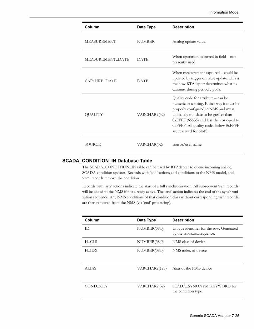
Information Model
SCADA_CONDITION_IN Database TableThe SCADA_CONDITION_IN table can be used by RTAdapter to queue incoming analog SCADA condition updates. Records with ‘add’ actions add conditions to the NMS model, and ‘rem’ records remove the condition.
Records with ‘syn’ actions indicate the start of a full synchronization. All subsequent ‘syn’ records will be added to the NMS if not already active. The ‘end’ action indicates the end of the synchroni-zation sequence. Any NMS conditions of that condition class without corresponding ‘syn’ records are then removed from the NMS (via ‘end’ processing).
MEASUREMENT NUMBER Analog update value.
MEASUREMENT_DATE DATEWhen operation occurred in field – not presently used.
CAPTURE_DATE DATE
When measurement captured – could be updated by trigger on table update. This is the how RTAdapter determines what to examine during periodic polls.
QUALITY VARCHAR2(32)
Quality code for attribute – can be numeric or a string. Either way it must be properly configured in NMS and must ultimately translate to be greater than 0xFFFF (65535) and less than or equal to 0xFFFF. All quality codes below 0xFFFF are reserved for NMS.
SOURCE VARCHAR(32) source/user name
Column Data Type Description
Column Data Type Description
ID NUMBER(38,0) Unique identifier for the row. Generated by the scada_in_sequence.
H_CLS NUMBER(38,0) NMS class of device
H_IDX NUMBER(38,0) NMS index of device
ALIAS VARCHAR2(128) Alias of the NMS device
COND_KEY VARCHAR2(32) SCADA_SYNONYM.KEYWORD for the condition type.
Generic SCADA Adapter 7-25
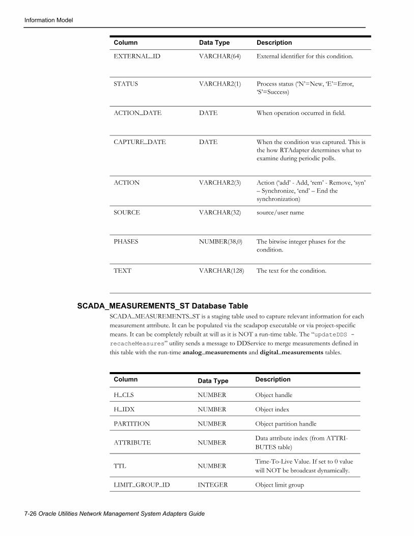
Information Model
SCADA_MEASUREMENTS_ST Database TableSCADA_MEASUREMENTS_ST is a staging table used to capture relevant information for each measurement attribute. It can be populated via the scadapop executable or via project-specific means. It can be completely rebuilt at will as it is NOT a run-time table. The “updateDDS -recacheMeasures” utility sends a message to DDService to merge measurements defined in this table with the run-time analog_measurements and digital_measurements tables.
EXTERNAL_ID VARCHAR(64) External identifier for this condition.
STATUS VARCHAR2(1) Process status (‘N’=New, ‘E’=Error, ‘S’=Success)
ACTION_DATE DATE When operation occurred in field.
CAPTURE_DATE DATE When the condition was captured. This is the how RTAdapter determines what to examine during periodic polls.
ACTION VARCHAR2(3) Action (‘add’ - Add, ‘rem’ - Remove, ‘syn’ – Synchronize, ‘end’ – End the synchronization)
SOURCE VARCHAR(32) source/user name
PHASES NUMBER(38,0) The bitwise integer phases for the condition.
TEXT VARCHAR(128) The text for the condition.
Column Data Type Description
Column Data Type Description
H_CLS NUMBER Object handle
H_IDX NUMBER Object index
PARTITION NUMBER Object partition handle
ATTRIBUTE NUMBERData attribute index (from ATTRI-BUTES table)
TTL NUMBERTime-To-Live Value. If set to 0 value will NOT be broadcast dynamically.
LIMIT_GROUP_ID INTEGER Object limit group
7-26 Oracle Utilities Network Management System Adapters Guide

Information Model
RTI_ALIAS VARCHAR2(128) RTI device measurement name
RTI_ALIAS_A VARCHAR2(128)RTI device measurement name for phase A - MultiSpeak status updates.
RTI_ALIAS_B VARCHAR2(128)RTI device measurement name for phase B - MultiSpeak status updates.
RTI_ALIAS_C VARCHAR2(128)RTI device measurement name for phase C - MultiSpeak status updates.
SCADA_ID INTEGERSCADA source identifier - matches scada_ids.id
RTU_ID VARCHAR2(32)RTU ID - unique name within SCADA system. Not generally used.
QUALITY INTEGER Quality code
VALUE FLOATCurrent value – from Manual Replace or from SCADA if configured for per-sistence.
UPDATE_FLAG INTEGER Update flag
ICCP_OBJECT VARCHAR2(32) ICCP mms object name
DISPLAY_ID VARCHAR2(64)ID for display call up – if different than rti_alias.
CONTROLLABLE VARCHAR2(1) Is this row controllable
ACTIVE VARCHAR2(1) Is this row active
SOURCE VARCHAR2(33) Source of measurements
COMMENTS VARCHAR2(512) Comment
NORMAL_STATE INTEGERNominal state – only used for Digital measurements.
OFF_NOMINAL_TIME DATE Time quality went off-nominal
MEASUREMENT_TYPE VARCHAR2(1) ‘A’ for Analog or ‘D’ for Digital.
FEEDER VARCHAR2(100) Nominal feeder
SUBSTATION VARCHAR2(100) Nominal substation
GANG VARCHAR2(1)Y/N is this a gang measurement or not - for topology status.
ICCP_DATA_SET VARCHAR2(64) ICCP Data Set
Column Data Type Description
Generic SCADA Adapter 7-27

Information Model
ANALOG_MEASUREMENTS Database TableThe ANALOG_MEASUREMENTS table is a run-time table generally maintained by DDService.
Column Data Type Description
H_CLS SMALLINT Object handle
H_IDX INTEGER Object index
PARTITION INTEGER Object partition handle
ATTRIBUTE SMALLINT Data attribute index (from ATTRIBUTES table)
TTL SMALLINT Time-To-Live Value
LIMIT_GROUP_ID INTEGER Object limit group
RTI_ALIAS VARCHAR2(128) RTI device measurement name
SCADA_ID INTEGER SCADA source identifier - matches scada_ids.id
RTU_ID VARCHAR2(32) RTU IDID - unique name within SCADA system.
QUALITY INTEGER Quality code
VALUE FLOAT Manual Replace Value
UPDATE_FLAG INTEGER Manual Replace Flag
ICCP_OBJECT VARCHAR2(32) ICCP mms object name
DISPLAY_ID VARCHAR2(64) ID for display call up
CONTROLLABLE VARCHAR2(1) Is this row controllable
ACTIVE VARCHAR2(1) Is this row active
SOURCE VARCHAR2(33) Source of measurements
COMMENTS VARCHAR2(512) Comment associated with
OFF_NOMINAL_TIME DATE Time quality went off-nominal
7-28 Oracle Utilities Network Management System Adapters Guide
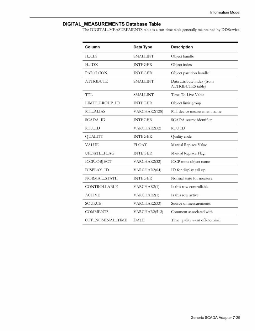
Information Model
DIGITAL_MEASUREMENTS Database TableThe DIGITAL_MEASUREMENTS table is a run-time table generally maintained by DDService.
Column Data Type Description
H_CLS SMALLINT Object handle
H_IDX INTEGER Object index
PARTITION INTEGER Object partition handle
ATTRIBUTE SMALLINT Data attribute index (from ATTRIBUTES table)
TTL SMALLINT Time-To-Live Value
LIMIT_GROUP_ID INTEGER Object limit group
RTI_ALIAS VARCHAR2(128) RTI device measurement name
SCADA_ID INTEGER SCADA source identifier
RTU_ID VARCHAR2(32) RTU ID
QUALITY INTEGER Quality code
VALUE FLOAT Manual Replace Value
UPDATE_FLAG INTEGER Manual Replace Flag
ICCP_OBJECT VARCHAR2(32) ICCP mms object name
DISPLAY_ID VARCHAR2(64) ID for display call up
NORMAL_STATE INTEGER Normal state for measure
CONTROLLABLE VARCHAR2(1) Is this row controllable
ACTIVE VARCHAR2(1) Is this row active
SOURCE VARCHAR2(33) Source of measurements
COMMENTS VARCHAR2(512) Comment associated with
OFF_NOMINAL_TIME DATE Time quality went off-nominal
Generic SCADA Adapter 7-29
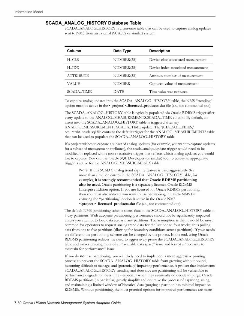
Information Model
SCADA_ANALOG_HISTORY Database TableSCADA_ANALOG_HISTORY is a run-time table that can be used to capture analog updates sent to NMS from an external (SCADA or similar) system.
To capture analog updates into the SCADA_ANALOG_HISTORY table, the NMS “trending” option must be active in the <project>_licensed_products.dat file (i.e., not commented out).
The SCADA_ANALOG_HISTORY table is typically populated via Oracle RDBMS trigger after every update to the ANALOG_MEASUREMENTS.SCADA_TIME column. By default, an insert into the SCADA_ANALOG_HISTORY table is triggered after any ANALOG_MEASUREMENTS.SCADA_TIME update. The $CES_SQL_FILES/ces_retain_scada.sql file contains the default trigger for the ANALOG_MEASUREMENTS table that can be used to populate the SCADA_ANALOG_HISTORY table.
If a project wishes to capture a subset of analog updates (for example, you want to capture updates for a subset of measurement attributes), the scada_analog_update trigger would need to be modified or replaced with a more restrictive trigger that reflects which analog updates you would like to capture. You can use Oracle SQL Developer (or similar) tool to ensure an appropriate trigger is active for the ANALOG_MEASUREMENTS table.
Note: If this SCADA analog trend capture feature is used aggressively (for more than a million entries in the SCADA_ANALOG_HISTORY table, for example), it is strongly recommended that Oracle RDBMS partitioning also be used. Oracle partitioning is a separately licensed Oracle RDBMS Enterprise Edition option. If you are licensed for Oracle RDBMS partitioning, then you must also indicate you want to use partitioning in Oracle NMS by ensuring the “partitioning” option is active in the Oracle NMS <project>_licensed_products.dat file (i.e., not commented out).
The default NMS partitioning scheme stores data in the SCADA_ANALOG_HISTORY table in 7 day partitions. With adequate partitioning, performance should not be significantly impacted unless you attempt to load data across many partitions. The assumption is that it would be most common for operators to request analog trend data for the last one to four weeks; thus pulling data from one to five partitions (allowing for boundary conditions across partitions). If your needs are different, the partitioning scheme can be changed by the project. In the end, using Oracle RDBMS partitioning reduces the need to aggressively prune the SCADA_ANALOG_HISTORY table and makes pruning more of an “available data space” issue and less of a “necessity to maintain for performance” issue.
If you do not use partitioning, you will likely need to implement a more aggressive pruning process to prevent the SCADA_ANALOG_HISTORY table from growing without bound, becoming difficult to manage, and (potentially) impacting performance. A project that implements SCADA_ANALOG_HISTORY trending and does not use partitioning will be vulnerable to performance degradation over time - especially when they eventually do decide to purge. Oracle RDBMS partitions (in particular) greatly simplify and optimize the process of capturing, using, and maintaining a limited window of historical data (purging a partition has minimal impact on RDBMS). Without partitioning, the most practical options for improved performance are more
Column Data Type Description
H_CLS NUMBER(38) Device class associated measurement
H_IDX NUMBER(38) Device index associated measurement
ATTRIBUTE NUMBER(38) Attribute number of measurement
VALUE NUMBER Captured value of measurement
SCADA_TIME DATE Time value was captured
7-30 Oracle Utilities Network Management System Adapters Guide

Information Model
aggressive pruning of the SCADA_ANALOG_HISTORY table and/or Oracle RDBMS hardware upgrades.
Any time a change is made to <project>_licensed_products.dat, the ces_setup.ces script must be executed to capture the desired licensed product changes and build the desired configuration. For NMS tables to be built as partitioned tables by the ces_setup.ces script, the NMS partitioning option must be active on a clean (initial) NMS model setup (ces_setup.ces -clean). The ces_setup.ces script will not convert existing non-partitioned tables to partitioned tables.
Note: If you have an existing (non-partitioned) NMS data model, are licensed to use partitioning, and you want to partition the SCADA_ANALOG_HISTORY table (without destroying your current data model), it is possible, but requires project specific effort beyond the scope of this document.
To help manage the pruning process for RDBMS history tables, NMS includes a pruning procedure called PURGE_HISTORY_TABLES, which is defined in the $CES_SQL_FILES/ product_flm.sql file. The procedure can be configured to retain a defined number of weeks of history via the CES_PARAMETERS table (as specified in the attrib='RETAIN_HISTORY_RECORDS' record).
Note: See $CES_SQL_FILES/ /product_parameters.sql for example configuration of the RETAIN_HISTORY_RECORDS parameter.
Once captured, the NMS client has configuration options to visualize trends for selected time slices of analog values in the SCADA_ANALOG_HISTORY table.
Generic SCADA Adapter 7-31

Information Model
External Access SchemaTo support external SCADA or ‘SCADA-like’ integration, NMS includes an optional limited NMS access RDBMS schema. This alternate schema is a set of RDBMS views, synonyms, and grants to access specific primary NMS RDBMS user tables (for the purpose of restricting access to only tables/views that an external SCADA type system needs to interact with NMS). This optional schema uses the NMS primary NMS RDBMS access username to help create the external SCADA access schema name. For example, if the primary NMS RDBMS user name is “nms,” then the external SCADA access schema would be “nms_scada.” The “nms_scada” schema name allows access to a subset of NMS RDBMS tables/views. The default tables/views/synonyms are defined by the SCADA_GRANTS_AND_SYNONYMS procedure in the $CES_SQL_FILES/ ces_schema_readonly.sql file.
The following tables are granted access by the SCADA_GRANTS_AND_SYNONYMS procedure:
• SCADA_VIEW: View of NMS measurements and current status
• SCADA_TAG_VIEW: View of active project specific tags to export to SCADA
• SCADA_IDS: Valid SCADA systems NMS can interact with
• SCADA_EMULATOR_ANALOG_OUT: Output from PFEmulator (for use with the Oracle Utilities Network Management System Training Simulator)
• SCADA_EMULATOR_DIGITAL_OUT: Output from PFEmulator (for use with the Oracle Utilities Network Management System Training Simulator)
• SCADA_ANALOG_IN: Access to SCADA_ANALOG_IN – for incoming analogs
• SCADA_DIGITAL_IN: Access to SCADA_DIGITAL_IN – for incoming digitals
• SCADA_CONDITION_IN: Access to SCADA_CONDITION_IN – for incoming tags
In particular, SCADA_VIEW is an RDBMS view that can be used by an external SCADA system to see what measurements NMS is currently configured for as well as the last known qualities and values NMS has recorded for those measurements. The intent of this view is that it can be used by the external SCADA system to not only know what measurements NMS is configured for, but also to use the corresponding last reported qualities and values to optimize re-sync (integrity check) processing. Presumably, an external SCADA could access this view and only send NMS updates for measures and qualities that do not sufficiently match what NMS has already recorded.
7-32 Oracle Utilities Network Management System Adapters Guide
DataRaker Integration
MultiSpeak Integration If desired, the generic SCADA adapter can be used in conjunction with the NMS MultiSpeak (Java-based) SCADA adapter. The intent is to use the RTAdapter to provide a buffering mechanism for “noisy” SCADA systems that could potentially generate many periodic analog (or digital) updates. Using RTAdapter to capture and bundle incoming changes reduces the impact on the NMS CORBA Gateway and NMS CORBA publisher. Using RTAdapter with the “-dir RDBMS” option allows changes to be captured and sent in bulk to internal NMS Services.
If configured to do so, the NMS Web Gateway APIs used by the MultiSpeak SCADA interface will write to the SCADA_DIGITAL_IN and SCADA_ANALOG_IN tables when processing updates from an external SCADA, rather than submitting them directly to DDService. This behavior is controlled by three configuration properties, which can be added to the CentricityServer.properties file.
1. intersys.use_db_for_scada_statuses
If set to 'true' than device status updates received from SCADA system will be written to the SCADA_DIGITAL_IN database table.
2. intersys.use_db_for_scada_digitals
If set to 'true' than updates to digital values received from SCADA system will be written to the SCADA_DIGITAL_IN database table.
3. intersys.use_db_for_scada_analogs
If set to 'true' than updates to analog values received from SCADA system will be written to the SCADA_ANALOG_IN database table
By default all the above properties are set to 'false', which means that SCADA measurements will be sent directly to the internal DDService process.
DataRaker IntegrationThe NMS RTAdapter can be configured to support integration with the Oracle DataRaker application. DataRaker captures large quantities of periodic Advanced Metering Infrastructure (AMI) data – typically once a day. AMI data typically includes usage information like meter load (kWH) and voltage for each interval – where intervals are typically hourly or every 15 minutes. By analyzing months (or more) of AMI usage data, DataRaker can detect a broad range of usage anomalies. A few examples include transformer overloads (by aggregating loads from all meters below the load transformer), voltage sags, voltage swells, and abnormal usage patterns.
If DataRaker analysis is routinely executed (for example, daily to pick up yesterday’s AMI data), it can be beneficial to make at least a subset of the DataRaker discovered anomalies clearly visible to NMS operators. RTAdapter can be configured to “import” a set of DataRaker discovered anomalies as NMS conditions (symbols that show in the NMS Viewer or simply records in the NMS Condition Summary tool). These DataRaker anomalies are captured as NMS conditions in the data_raker RDBMS table via the RTAdapter. Once captured, these NMS conditions allow navigation back into DataRaker from NMS.
DataRaker provides raw data files (in DataRaker export file format) that must be mapped/translated to the RTAdapter formats noted below. Typically DataRaker would generate raw DataRaker export files containing the desired data on a relatively routine (daily or weekly) basis. The raw DataRaker files must be transformed (via project specific adapters) into the specified RTAdapter format files for subsequent consumption. A project specific adapter (likely a perl or python script) must be used to translate the DataRaker export format file into the RTAdapter import format data file. This allows a project to determine what DataRaker data they want to include/exclude and how they want to categorize the input data for their NMS operators.
Generic SCADA Adapter 7-33

DataRaker Integration
The following three use cases describe how the DataRaker to NMS data integration can be managed by a project using the RTAdapter. The first use case is expected to be the most common – the others are options for NMS administrators to consider as necessary.
Use Cases
Use Case 1 – DataRaker Master (Minimal NMS Involvement)For this use case, DataRaker is the master of all DataRaker discovered anomalies. This means the anomalies generated by a new DataRaker analysis execution completely replace whatever DataR-aker anomalies (NMS conditions) that were previously reported to (or captured by) NMS. This has the advantage of not requiring any periodic updates from NMS operators. NMS operators can view the DataRaker conditions if they choose, act on them if they have time, etc., but they can also ignore the DataRaker conditions and be confident they will not accumulate in NMS over time.
To accomplish this, RTAdapter must be configured to scan files (not the RDBMS) for this instance of the adapter. Below is an example RTAdapter record from the system.dat file that could be applicable for this case:
program DataRaker RTAdapter -scada dataraker -interval 60 -dir ~/dataraker
This means this RTAdapter instance will be known as DataRaker internal to NMS (on the mes-sage bus) and will look for configuration records that match scada_ids.id where scada_ids.scada_name=‘dataraker’ in the SCADA_IDS RDBMS table. This id will then need to be matched by appropriate configuration in the SCADA_SYNONYMS and SCADA_STATES tables for this DataRaker instance of the RTAdapter. Note there is no required SCADA_STATES table configuration so it will not be further discussed in this section.
Example configuration:
• Records in the RTAdapter SCADA_SYNONYMS configuration table for DataRaker configuration use SCADA_IDS.ID=100 where SCADA_IDS.SCADA_NAME=’dataraker’ (to match example system.dat configuration noted above).
• The SCADA_SYNONYMS table configuration records noted below will allow the RTAdapter to process add, rem(ove) and syn(chronize) directive records from an RTAdapter input file for a single type of DataRaker condition (where NMS data_raker condition status=10). See the example OPAL_scada.sql file for more examples of DataRaker conditions. By default the NMS OPAL model is configured to handle 3 different DataRaker condition class statuses (Info=10, Warn=20, Alarm=30). To utilize OPAL type configuration the DataRaker Info, Warn and Alarm conditions must have the specified condition status values of 10, 20 and 30 respectively. These values are somewhat arbitrary and can be changed if necessary – but will require more project specific configuration. Entries for “DR_E2” are similar – just change status_value=‘20’. Entries for “DR_E3” are also similar – just change status_value=‘30’.
INSERT into scada_synonyms (id, scada_id, keyword, value, process_type, attribute_alias, status_value) VALUES (tmp_seq.nextval, 100, 'DR_E1', 'add', 'C', 'data_raker', '10');
INSERT into scada_synonyms (id, scada_id, keyword, value, process_type, attribute_alias, status_value) VALUES (tmp_seq.nextval, 100, 'DR_E1', 'rem', 'C', 'data_raker', '10');
INSERT into scada_synonyms (id, scada_id, keyword, value,
7-34 Oracle Utilities Network Management System Adapters Guide
DataRaker Integration
process_type, attribute_alias, status_value) VALUES (tmp_seq.nextval, 100, 'DR_E1', 'syn', 'C', 'data_raker', '10');
Technically only the “syn” entry above is required for the first use case option (use RTAdapter to periodically synchronize DataRaker conditions). The “add” and “rem” options are configured just in case a project wants RTAdapter to also process individual add/rem directives in the RTAdapter input file. They are not required, but are used for Use Case 2 and Use Case 3.
Below is an example (translated) DataRaker export file suitable for RTAdapter consumption. You can give the file any valid file name, but it must ultimately be placed in the directory specified via “RTAdapter –dir <directory>” before it will be processed. The RTAdapter data files in the specified directory are processed in a first in, first out basis. The “OBJECT” keyword specifies an NMS object that must match an RTAdapter configured rti_alias (from scada_measurements_st.rti_alias) or an alias entry in the alias_mapping table where db_type='OPS' (default alias).
Any data_raker records in NMS that are NOT found in a RTAdapter synchronization input file will be deleted (based on the value of the external id provided by the EXT= keyword). NMS should only be left with conditions that are specified in the RTAdapter synchronization file when processing is completed. The pipe symbol “|” is a delimiter and can be changed via the RTAdapter –delimter <n> command line option. Replace “|” with your project specified delimiter in the examples below, if necessary:
SYNCHRONIZE|TRUETYPE|data_rakerDATA OBJECT|xfmr_1 DR_E1|syn|WHO=dataraker|TIM=2009-02-27T16:22:17|TXT=Over voltage detected|EXT=DR_E1-1 DR_E1|syn|WHO=dataraker|TIM=2009-02-27T17:22:17|TXT=Xfmr within 50% of capacity|EXT=DR_E1-2 DR_E2|syn|WHO=dataraker|TIM=2009-02-27T18:22:17|TXT=Xfmr within 75% of capacity |EXT=DR_E2-1OBJECT|xmfr_2 DR_E3|syn|WHO=dataraker|TIM=2009-02-27T16:22:17|TXT=Xfmr within 100% of capacity|EXT=DR_E3-1 DR_E3|syn|WHO=dataraker|TIM=2009-02-27T19:22:17|TXT=Xfmr 120% of capacity|EXT=DR_E3-2END_DATA
Detailed field descriptions of RTAdapter keywords:
• SYNCHRONIZE|TRUE is a keyword sequence that says this entire file is a synchronization file. Always specify exactly as noted for a synchronization file request. Must start in column 1.
• TYPE is a keyword that specifies what condition class the synchronization will focus on for all subsequent entries (data_raker in the above example). All entries in a given RTAdapter synchronization file must be of the same class. Must start in column 1.
• OBJECT is a keyword that precedes the common object id between NMS and DataRaker – as this is the link between the two systems. Normally this is a transformer alias.
• Project configured keywords – defined in scada_synonyms table
• DR_E1 indicates we are dealing with a DataRaker “Info condition”.
• DR_E2 indicates we are dealing with a DataRaker “Warn condition”.
• DR_E3 indicates we are dealing with a DataRaker “Alarm condition”.
Generic SCADA Adapter 7-35

DataRaker Integration
• syn is a directive keyword that indicates we want to make sure this condition exists in NMS. It will update an existing condition or (if there is no current matching condition based on the EXT id) it will insert a new one.
• WHO= is a keyword that indicates what external system to indicate as the source of the condition directive. Normally this would be “dataraker” (or similar) for DataRaker integration.
• TIM= is a keyword that specifies a timestamp to go with the directive. Generally from the external system and must be specified in ISO format (the format you see above YYYY-MM-DDTHH:MM:SS – where hours are 00->24 and local time zone is assumed).
• TXT= is a keyword that specifies a brief summation of the condition detected. Can be up to 512 characters, but less is generally more. Suggest this be just enough to convey the type of issue detected – at least on first 30 characters of the text or so.
• EXT= is a keyword that specifies the unique external id for this condition. This should be the primary key for this condition. It could be generated by DataRaker or it could be generated by the NMS translation process. Ultimately it should be unique for at least every transformer and data_raker condition status combination in play (project specific).
Notes on the NMS unique key (EXT=) field. If DataRaker reports an anomaly for NMS trans-former “xfmr_1” that maps to an NMS data_raker alarm (status=10) today – we could set the EXT= value to “xfmr_1-10” – indicating there is a data_raker alarm (status=10) on xfmr_1. This way if tomorrow DataRaker reports the same (or essentially the same) condition we would again translate to “xfmr_1-10” – and nothing would change on the NMS side for this condition. This scheme minimizes processing in NMS and allows “old” NMS data_raker conditions to “age” within NMS. This should provide some indication of how long DataRaker has been reporting sim-ilar issues for this transformer, which may be useful to NMS operators. Otherwise the conditions will be reported as new every day.
Use Case 2 – DataRaker Only Inputs New Conditions – NMS DeletesUse Case 2 can use the same configuration as Use Case 1 other than the format of the input file to RTAdapter. Here DataRaker only inputs new conditions into NMS and NMS operators have the option to view/add/delete DataRaker conditions as necessary. If/when subsequent DataRaker input is processed, it will be captured “in addition to” whatever DataRaker conditions were already present within NMS. Ideally, for this use case, NMS operators would delete all (old) DataRaker conditions before processing a new batch of DataRaker conditions. If the operators do not delete the old DataRaker conditions they will tend to accumulate.
This option may be useful if it becomes necessary to leave some DataRaker conditions on the system for a substantial period of time before they are acted on and you do not want to automatically remove previously imported DataRaker conditions during every import (like the “SYNCHRONIZE” option does in Use Case 1). Maybe one execution of DataRaker finds conditions of one type and the next iteration finds conditions of another and you do not want to delete the records from the first pass before applying the second (or similar). The format for the input file would be similar to what follows. The primary differences are that there is no SYNCHRONIZE or TYPE keywords and (instead of the directive “syn”) we use the “add” action directive.
DATA OBJECT|xfmr_1 DR_E1|add|WHO=dataraker|TIM=2009-02-27T16:22:17|TXT=Over voltage detected|EXT=DR_E1-1 DR_E1|add|WHO=dataraker|TIM=2009-02-27T17:22:17|TXT=Xfmr within 50% of capacity|EXT=DR_E1-2 DR_E2|add|WHO=dataraker|TIM=2009-02-27T18:22:17|TXT=Xfmr within 75% of capacity |EXT=DR_E2-1OBJECT|xmfr_2
7-36 Oracle Utilities Network Management System Adapters Guide

DataRaker Integration
DR_E3|add|WHO=dataraker|TIM=2009-02-27T16:22:17|TXT=Xfmr within 100% of capacity|EXT=DR_E3-1 DR_E3|add|WHO=dataraker|TIM=2009-02-27T19:22:17|TXT=Xfmr 120% of capacity|EXT=DR_E3-2END_DATA
Use Case 3 – Bulk Delete for NMS ConditionsUse Case 3 can use the same configuration as Use Case 1 other than the format of the input file processed by RTAdapter. In this use case, the RTAdapter input file specifies what conditions to delete from NMS. The creation of this form of input file would need to be done by the NMS project implementers. This option may be useful if an NMS administrator wants to automatically delete some subset of previously applied DataRaker conditions (for whatever reason). The format of the input file is similar to Use Case 2 except that no “TXT=” data is processed. All other fields are processed and can be captured in the NMS data_raker condition table. Note that “add” and “rem” records can also be combined in the same file, but must be specified in proper order (“del” must follow an “add” for same condition, for example).
DATA OBJECT|xfmr_1 DR_E1|rem|WHO=dataraker|TIM=2009-02-27T16:22:17|EXT=DR_E1-1 DR_E1|rem|WHO=dataraker|TIM=2009-02-27T17:22:17|EXT=DR_E1-2 DR_E2|rem|WHO=dataraker|TIM=2009-02-27T18:22:17|EXT=DR_E2-1OBJECT|xmfr_2 DR_E3|rem|WHO=dataraker|TIM=2009-02-27T16:22:17|EXT=DR_E3-1 DR_E3|rem|WHO=dataraker|TIM=2009-02-27T19:22:17|EXT=DR_E3-2END_DATA
Generic SCADA Adapter 7-37

DataRaker Integration
7-38 Oracle Utilities Network Management System Adapters Guide

Chapter 8ICCP Adapter
This chapter includes the following topics:
• ICCP Adapter Overview
• LiveData ICCP Adapter Configuration
• TMW ICCP Adapter Configuration
ICCP Adapter Overview The Oracle Utilities Network Management System ICCP Adapter integrates the Oracle Utilities Network Management System with a remote SCADA system through the Inter-control Center Communications Protocol (ICCP). Oracle offers two versions of an ICCP adapter. One Oracle ICCP adapter (TMW ICCP Adapter) uses ICCP libraries from Triangle MicroWorks (TMW) and can interface directly to a 3rd-party SCADA system that supports the ICCP protocol. The other Oracle ICCP adapter (LiveData ICCP Adapter) does not directly speak ICCP, but instead interfaces to a LiveData 3rd-party ICCP server using LiveData proprietary APIs, which then interfaces to the SCADA system that supports the ICCP protocol.
Note: TMW ICCP Adapter includes the TWM libraries bundled in. The LiveData ICCP Adapter requires the use of a LiveData Server that must be separately licensed from LiveData, Inc. For additional details on the LiveData Server, please refer to LiveData documentation.
ICCP is a standard interface protocol that can be used with Oracle Utilities Network Management System to provide data exchange with remote and local SCADA systems. ICCP is also an international standard: International Electrotechnical Commission (IEC) Telecontrol Application Service Element 2 (TASE.2).
ICCP allows the exchange of real-time and historical power system monitoring and control data, including measured values, scheduling data, energy accounting data, and operator messages. Data exchange can occur between:
• Multiple control center Energy Management System (EMS) systems
• EMS and power plant DCS systems
• EMS and distribution SCADA systems
• EMS and other utility systems
• EMS/SCADA and substations
ICCP Adapter 8-1

LiveData ICCP Adapter Configuration
The ICCP standard consists of the following blocks:
LiveData ICCP Adapter ConfigurationThis section guides the user through configuration of the Oracle Utilities Network Management System LiveData ICCP Adapter. The following are assumed to be true before the adapter is installed:
• Oracle database access has been confirmed.
• Isis messaging bus has been installed and verified.
• Oracle Utilities Network Management System is installed and functional.
• LiveData Server is installed, functional, and licensed.
The adapter reloads its configuration file and measurements configuration each time connection to LiveData server is lost.
Configuring the ICCP Adapter requires:
• Configuring the Adapter to Run as a System Service
• Populating the NMS Measurements Tables
Block Description Notes
Block 1 Basic Services Available via both the Oracle TMW ICCP Adapter and the Oracle LiveData ICCP Adapter.
Block 2 Extended Data Set Condition Monitoring Available via both the Oracle TMW ICCP Adapter and the Oracle LiveData ICCP Adapter.
Block 3 Blocked Transfers
Block 4 Operator Stations
Block 5 Device Control Currently only available via the Oracle LiveData ICCP Adapter.
Block 6 Programs
Block 7 Events
Block 8 Accounts
Block 9 Time Series
8-2 Oracle Utilities Network Management System Adapters Guide

LiveData ICCP Adapter Configuration
Configuring the Adapter to Run as a System ServiceConfigure the ICCP Adapter by updating the $NMS_HOME/etc/system.dat file to include the ICCP Adapter as a system service. There are three main sections where this service needs to be defined: the service, program and instance sections. See the $CES_HOME/templates/system.dat.template file for examples of how to configure the ICCP Adapter. Search for IccpAdapter and make sure those lines are uncommented. You must restart the system services in order for the ICCP Adapter to be properly monitored by SMService.
Below is an example of the program section in the system.dat file:
program IccpAdapter IccpAdapter -prm_path /users/nms1/etc/
Note: It is assumed that the ICCP Adapter will reside on the same Unix or Linux server where the Oracle Utilities Network Management System services environment resides.
Command Line Options for ICCP AdapterThe command line for the ICCP Adapter provides the following options:
Command Line Option What it does
-debug <level> Sets the level of debug messages generated by the adapter. <level> is a positive number, or zero. The higher the number, the more information is displayed. If <level> is omitted, it defaults to a value of 0. Debug facilities can also be specified on the command line; for example:
-debug IA_RTP 3
could be used to specifiy level 3 debug for the IA_RTP debug facility.
-prm_path <IccpAdapter.prm path>
Sets the path of the IccpAdapter.prm parameter file location. This file is used to configure the operation of the ICCP adapter.
-help Returns the available IccpAdapter startup parameters and definitions, then terminates.
-nodaemon Runs in the foreground, used when running by hand.
ICCP Adapter 8-3

LiveData ICCP Adapter Configuration
IccpAdapter.prmThe IccpAdapter.prm file is used to configure the operation of the Oracle Utilities Network Management System ICCP Adapter. The default location for this file is the same as where the IccpAdapter binary is located (i.e., $CES_HOME/bin) but it is generally configured to be in a different location by using the –prm_path <IccpAdapter.prm path> command line option. Lines in this file beginning with a “;” (semi-colon) are comments. Lines beginning with a “[” (left bracket) are block identifiers (markers). Fields marked as <Required> must be configured for proper operation and are generally site specific. See the IccpAdapter.prm.template file in the standard $CES_HOME/templates directory for an example IccpAdapter configuration file.
Fields in the IccpAdapter.prm File
Field name Type Default Valid Values Description
[IccpAdapter] Marker Used for generic configuration of program.
ServerHostname IP addressList – blankseparated
<Required> 128.168.148.43 etc
The IP address(es) of the LiveData Server hostname(s) to connect to. It could be a blank separated list of IP address of several LiveData Servers. In case a failure of connection was detected by the ICCP Adapter with the current LiveData Server, it will traverse the ServerHostname list for the next LiveData Server to connect to.
Port Integer <Required> [1..MAX_INT] Blank separated list of TCP/IP port numbers that the ICCP Adapter will use for a connection attempt to a LiveData Server. Parallel to the ServerHostname, it could be a list of port numbers to use to connect to the corresponding LiveData server in ServerHostname. In case there was a failure of connection with the current LiveData Server, it would proceed to the next entry - in parallel with the next ServerHostname entry. 5002 is typical.
Period Integer 10 [1..MAX_INT] Time in seconds between periodic transfers of non-time critical data.
StatusUpdates Integer 25 [1..MAX_INT] The maximum number of status updates to be sent to DDService at one time.
ScadaId Integer 1 [1..MAX_INT] Identification number assigned to the SCADA in Oracle Utilities Network Management System with which the ICCP Adapter is communicating.
AnalogTolerance Double 0.0F [0.01..0.99] Dead band for analog value updates. It is the required percent change from the last reported value to trigger an update.
Analogs Boolean F [T, F] Boolean value indicating use of the ANALOG_MEASUREMENTS table.
8-4 Oracle Utilities Network Management System Adapters Guide

LiveData ICCP Adapter Configuration
Digitals Boolean T [T, F] Boolean value indicating use of the DIGITAL_MEASUREMENTS table.
ReconnectPeriod Integer 60 [0..MAX_INT] Configurable duration of delay to wait after the LiveData Server instances failed in succession.
Controls Boolean F [T, F] Boolean value indicating use of the controls table for Block 5 functionality.
QualityCodeUseOnAssociationTimeOut
Integer 0 [0..MAX_INT] Quality code that will be sent to DDService when the communication with LD server is lost. A valid QualityCode must be specified if this option is used.
DisableStop Boolean F [T, F] Normally the adapter will accept and process a stop high level message. This option disables this feature. When this feature is enabled, the adapter will disregard a stop high level message.
DisableCOV Boolean F [T, F] Normally the adapter will process a COV update (one or more open and close sequences within a scan cycle – normally indicating one or more momentaries) and send it to DDService. This option disables this feature.
Vccs Integer <Required> [1..MAX_INT] The number of VCCs (Virtual Control Centers) that are configured in the LiveData Server.
IgnoreCritInterSysServFail Boolean F [T, F] Normally the adapter will stop if SMSserivce reports a critical service failure and not restart until services are recovered. This option disables this feature.
NoSwitchOpQualityMask Integer No Mask [0..MAX_INT] This parameter sets the quality codes that prevent switches from being operated. There is no effect on non-switch statuses.
PhaseEncodeSwitch Boolean F [T, F] If set to true, this will enable Iccp Adapter to interpret data discrete values as three-bit phase encoded statuses. [e.g., A = ‘001’, B = ‘010’, C = ‘100’, etc.]
PseudoAlarms Boolean F [T, F] If set to 1, then this will set the pseudo flag for the switch entry to be sent to DDService. Generates pseudo (advisory) alarms for ICCP reported device ops rather than actually operating the switches in the Oracle Utilities Network Management System model.
Field name Type Default Valid Values Description
ICCP Adapter 8-5
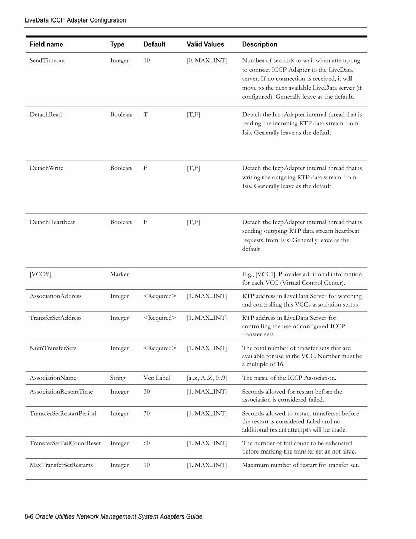
LiveData ICCP Adapter Configuration
SendTimeout Integer 10 [0..MAX_INT] Number of seconds to wait when attempting to connect ICCP Adapter to the LiveData server. If no connection is received, it will move to the next available LiveData server (if configured). Generally leave as the default.
DetachRead Boolean T [T,F] Detach the IccpAdapter internal thread that is reading the incoming RTP data stream from Isis. Generally leave as the default.
DetachWrite Boolean F [T,F] Detach the IccpAdapter internal thread that is writing the outgoing RTP data stream from Isis. Generally leave as the default
DetachHeartbeat Boolean F [T,F] Detach the IccpAdapter internal thread that is sending outgoing RTP data stream heartbeat requests from Isis. Generally leave as the default
[VCC#] Marker E.g., [VCC1]. Provides additional information for each VCC (Virtual Control Center).
AssociationAddress Integer <Required> [1..MAX_INT] RTP address in LiveData Server for watching and controlling this VCCs association status
TransferSetAddress Integer <Required> [1..MAX_INT] RTP address in LiveData Server for controlling the use of configured ICCP transfer sets
NumTransferSets Integer <Required> [1..MAX_INT] The total number of transfer sets that are available for use in the VCC. Number must be a multiple of 16.
AssociationName String Vcc Label [a..z, A..Z, 0..9] The name of the ICCP Association.
AssociationRestartTime Integer 30 [1..MAX_INT] Seconds allowed for restart before the association is considered failed.
TransferSetRestartPeriod Integer 30 [1..MAX_INT] Seconds allowed to restart transferset before the restart is considered failed and no additional restart attempts will be made.
TransferSetFailCountReset Integer 60 [1..MAX_INT] The number of fail count to be exhausted before marking the transfer set as not alive.
MaxTransferSetRestarts Integer 10 [1..MAX_INT] Maximum number of restart for transfer set.
Field name Type Default Valid Values Description
8-6 Oracle Utilities Network Management System Adapters Guide

LiveData ICCP Adapter Configuration
TransferSetControlMask String <Required> [T, F] Transfer set control mask for the transfer set to be sent to LiveData Server. One T/F flag for each TransferSet. String length must be a multiple of 16.Example with one TransferSet enabled: "FTTTTTTTTTTTTTTT"
[ValidityQuality] Marker Assign an Oracle Utilities Network Management System quality to ICCP Validity Quality values
Valid Integer 0 2**n (n=11->31) The value is valid. This is the default (normal) value should virtually always be 0.
Held Integer 0 2**n (n=11->31) Previous data value has been held over. Interpretation is local.
Suspect Integer 0 2**n (n=11->31) Data value is questionable. Interpretation is local.
Notvalid Integer 0 2**n (n=11->31) The value is not valid.
[CurrentSourceQuality] Marker Assign an Oracle Utilities Network Management System quality to ICCP Current Source Quality values.
Telemetered Integer 0 2**n (n=11->31) Value was received from a telemetered site. This is the default (normal) value should virtually always be 0.
Calculated Integer 0 2**n (n=11->31) Value was calculated based on other data.
Entered Integer 0 2**n (n=11->31) Value was entered manually.
Estimated Integer 0 2**n (n=11->31) Value was estimated (State Estimator, etc.).
[NormalValueQuality] Marker Assign an Oracle Utilities Network Management System quality to ICCP Normal Value Quality values.
Normal Integer 0 2**n (n=11->31) The point value is that which has been configured as normal for the point. This is the default (normal) value should virtually always be 0.
Abnormal Integer 0 2**n (n=11->31) The point value is not that which has been configured as normal for the point.
[TimeStampQuality] Marker Assign an Oracle Utilities Network Management System quality to ICCP Timestamp Quality values
Valid Integer 0 2**n (n=11->31) Current value of the TimeStamp attribute contains the time stamp of when the value was last changed. This is the default (normal) value should virtually always be 0.
Field name Type Default Valid Values Description
ICCP Adapter 8-7

LiveData ICCP Adapter Configuration
Quality CodesThe IccpAdapter.prm file enables ICCP quality codes to be translated into Oracle Utilities Network Management System quality codes. In the simplest (and default) configuration, all of the ICCP quality codes (except the Between and Invalid SwitchStatusQuality codes, which need to be defined to ensure proper operation) are assigned to the 'normal' Oracle Utilities Network Management System quality code (0).
Note: Oracle Utilities Network Management System quality codes are always single bit values. Therefore, the only valid value for configuration is 0 or a proper value of 2^nth power where n=0->31. The Quality Rules Table on page 8-26 table lists all the valid user-defined quality codes in Oracle Utilities Network Management System.
If none of the predefined quality codes are applicable, then a new code must be created. The following steps accomplish this:
• Choose an ICCP quality listed in the IccpAdapter.prm.
• Check the Quality Rules Table to see which values have already been assigned to qualities.
• Assign one of the values listed below to the ICCP quality and enter it in the Quality Rules Table.
• Locate the quality in the IccpAdapter.prm file and enter the assigned value for it.
The assigned value must be the decimal representation of 32 bits, where no more than one bit has a value of 1. For example, if the bit position is 11, use the number 2048. The following list contains the decimal values that may be assigned to new qualities: 2048, 4096, 8192, 16384, 32768, 65536, 131072, 262144, 524288, 1048576, 2097152, 4194304, 8388608, 16777216, 33554432, 67108864, 134217728, 268435456, 536870912, 1073741824, 2147483648.
Values of 0, 1, 2, 4, 8, 16, 32, 64, 128, 256, 512, 1024 may not be assigned as codes for new qualities because they are already defined and used within Oracle Utilities Network Management System. The ‘normal’ Oracle Utilities Network Management System quality code is 0.
The adapter reads the IccpAdapter.prm file only during startup. If the quality code is added when the adapter is running, you must restart the adapter in order for it to recognize the new quality code.
Invalid Integer 0 2**n (n=1->31) Current value of the TimeStamp attribute contains the time stamp other than when the value was last changed.
[SwitchStatusQuality] Marker Assign an Oracle Utilties Network Management System quality to the non-open/close statuses that can be returned in the two-bit ICCP status field. ICCP “open” is generally (1) and “closed” is (2).
Between Integer 262144 2**n (n=11->31) Quality code to set if the two bit ICCP switch status is reported as “between” (0).
Invalid Integer 524288 2**n (n=11->31) Quality code to set if the two bit ICCP switch status is reported as “invalid” (3).
Field name Type Default Valid Values Description
8-8 Oracle Utilities Network Management System Adapters Guide

LiveData ICCP Adapter Configuration
High Level MessagesThe ICCP Adapter can be dynamically controlled from Oracle Utilities Network Management System by using high-level messages. They can be used any time while running the Oracle Utilities Network Management System ICCP Adapter. The following high-level messages can be used:
• stop
Disconnect from the LiveData Server and stop the Oracle Utilities Network Management System ICCP Adapter.
• report
Empty message to determine how many Oracle Utilities Network Management System ICCP Adapters are running.
• debug [on | off | #]
Turn on/off debug, or set it to a specific level. On is equivalent to 1, off is 0. Level can be any integer value no less than 0.
• debug <facility> #
Turn facility specific debug on/off. For example, to turn IA_RTP debug on to level 3:
Action any.IccpAdapter debug IA_RTP 3
To turn off:
Action any.IccpAdapter debug IA_RTP 0
Check ICCP Adapter specific log file for other facilities specific to this adapter process.
• demote
Causes the Oracle Utilities Network Management System ICCP Adapter currently in control to relinquish control.
Use IccpAdapterService with high-level messages for the Oracle Utilities Network Management System ICCP Adapter. For example:
Action any.IccpAdapter report
ICCP Adapter 8-9

LiveData ICCP Adapter Configuration
Populating the NMS Measurements TablesICCP points must first be mapped to devices in the Oracle Utilities Network Management System model before sending SCADA updates to Oracle Utilities Network Management System. These ICCP points are placed in SCADA Measurements table of the Oracle Utilities Network Management System database. A process needs to be formalized to create and maintain this data. This process often depends on customer specific mechanisms used to maintain the SCADA side of the ICCP interface. As a result this process generally needs to be formalized by LiveData and the customer - potentially with help from NMS consulting.
Required NMS Data from LiveDataThe following data items are required to be populated in the NMS measurements tables:
• ICCP Name
• ICCP Type
• Attribute
• NMSDeviceID
ICCP Name• ICCP Name has to be unique.
• It is recommended for the name to be composed of alpha-numeric characters and underscore
• It is recommended for the first character of the ICCP Name to be a letter
• There should be no space, no periods and no dashes in the ICCP name.
ICCP TypeBelow is a list of supported ICCP Types. Please take note of the underscore.
• Data_State
• Data_StateQ
• Data_StateQTimeTag
• Data_StateExtended
• Data_Real
• Data_RealQ
• Data_RealQTimeTag
• Data_RealExtended
• Data_Discrete
• Data_DiscreteQTimeTag
• Data_DiscreteExtended
Attribute• The attribute should have a corresponding entry in the ATTRIBUTES table, specifically, in
the NAME field in the Oracle Utilities Network Management System database. Take note that entries under the attributes column of the flat file needs to exactly match the entries in the NAME field of the ATTRIBUTES table, taking into consideration case sensitivity, underscores, etc.
8-10 Oracle Utilities Network Management System Adapters Guide

LiveData ICCP Adapter Configuration
NMSDeviceID• This is the ID of the SCADA device. This ID should match a unique attribute or device name
in NMS that will allow the measurement table population process to grab the appropriate NMS device handle (h_cls and h_idx) of the SCADA device. Tables that could be used in NMS to reference SCADA devices handles could be SCADA_POINTS, ALIAS_MAPPING, or a model managed device attribute table such as ATT_SWITCH.
Information Model - Database Schema
Quality Rules TableThis database table will define the quality codes that may be used for analog and digital values. This table defines the meaning of each bit in the quality codes for SCADA measurements.
Note: If multiple bits in the quality code are set, then the color of the measurement text in the Viewer is determined by the color of the lowest order bit that is set in the quality code.
Column Name Data Type Size Description Values
PRIORITY NUMBER Ranking priority of the quality code Priority code, specifies relative importance of this quality bit over other quality bits
VALUE NUMBER Bit value used for the quality code change.
For Phase 1:2048=No Data4096=Old Data
STRING VARCHAR2 3 Description of the quality code, which is displayed next to the value of the measurement when a quality exists for a measurement change.
The actual character string displayed next to the device when viewed via the Viewer
DESCRIPTION VARCHAR2 128 Descriptive string Any text string-usually the action taken from the SCADA Summary
COLOR NUMBER Designates which color is used in the Viewer to display the measurement when a particular quality bit is set. Integer value for the color associated to the quality code change to be displayed
The integers are mapped to the pre-allocated colors documented in separate application file.
LOCATION NUMBER Location of symbol in relation to the device associated with the value.only used if a symbol is defined for the quality code as opposed to just a color for a quality change
1-9; 5 overrides the device symbol
SYMBOL NUMBER The symbol used to display the value. only used if a symbol is defined for the quality code as opposed to just a color for a quality change
Valid Symbol Identification Number defined in <project>_SYMBOLS.sym. 0 if defining a text symbol.
OFF_NOMINAL VARCHAR2 1 Whether or not the value is off-nominal
Y or N
ICCP Adapter 8-11

LiveData ICCP Adapter Configuration
SCADA Measurements TableThe SCADA_MEASUREMENTS_ST table defines digital and analog measurements as used by Oracle Utilities Network Management System. It is a staging table used by DDService for populating the production SCADA measurements tables (ANALOG_MEASUREMENTS and DIGITAL_MEASUREMENTS).
The Oracle Utilities Network Management System ICCP Adapter communicates dynamic information to the Oracle Utilities Network Management System services. The services will cache measurements defined by this table. Population is dependent upon customer-supplied information.
Column Name Data Type Size Description Values
MEASUREMENT_TYPE
VARCHAR2 1 Measurement type code. A (analog)D (digital)
H_CLS NUMBER Class component of handle Valid object class
H_IDX NUMBER Index component of handle >0
PARTITION NUMBER Partition number, index component of partition handle
Valid partition or 0 for multi-partition objects
ATTRIBUTE NUMBER Attribute number which identifies measurement type
Valid attribute number
TTL NUMBER Setting for displaying measurement value in the Viewer or not.
1 or 0. 1=yes
LIMIT_GROUP_ID NUMBER Limit group ID Customer defined
RTI_ALIAS VARCHAR2 128 Alias to be used in communications between the Oracle Utilities Network Management System ICCP Adapter and LiveData Server
Alphanumeric
SCADA_ID NUMBER SCADA host ID 0 (not a SCADA device), 1 (SCADA 1), 2 (SCADA 2)...
RTU_ID VARCHAR2 32 SCADA RTU ID String (optional)
QUALITY NUMBER Measurement quality code Bit mask of quality codes
VALUE NUMBER Measurement/entered value Entered value
UPDATE_FLAG NUMBER Manual replace flag 1=true, 0=false
ICCP_OBJECT VARCHAR2 32 ICCP Object type of the telemetered value
Alphanumeric
DISPLAY_ID VARCHAR2 64
NORMAL_STATE NUMBER
CONTROLLABLE VARCHAR2 1
8-12 Oracle Utilities Network Management System Adapters Guide

LiveData ICCP Adapter Configuration
SCADA Controls TableThe SCADA_CONTROLS table defines control actions as used by Oracle Utilities Network Management System. Population is dependent upon customer-supplied information. The information to be contained in this table is generated by the Auto Configuration Program.
ACTIVE VARCHAR2 1 Active flag for patch management, indicates whether the row is active within the model
Y(yes=active), N(no=inactive), A(local add=active), D(local delete=inactive), R(locally removed, dependent=inactive)
SOURCE VARCHAR2 33 Source of the measurement. any character string.
OFF_NOMINAL_TIME
DATE
Column Name Data Type Size Description Values
Column Name Data Type Size Description Values
H_CLS NUMBER Class component of device handle. Valid object class
H_IDX NUMBER Index component of device handle.
>0
NMS_ACTION NUMBER The Control Action ID number associated to the action.
Valid control action ID.1 (OPEN),2 (CLOSE)…
EXT_ACTION NUMBER Part of unique key to identify each external control action for a single device.
0..N, based on the number of control actions defined for the device.
ATTRIBUTE NUMBER If non-zero, attribute number which identifies measurement type.
0 (Ignore) orValid attribute number
RTI_ALIAS VARCHAR2 128 Alias to be used in communications between the Oracle Utilities Network Management System ICCP Adapter and LiveData Server.
Alphanumeric
TIMEOUT NUMBER SCADA timeout for this device. 0 = No Timeout, >0 = timeout is seconds.
SCADA_ID NUMBER SCADA server ID. 0 (not a SCADA device), 1 (SCADA 1), 2 (SCADA 2)...
RTU_ID VARCHAR2 64 SCADA RTU ID. String (optional)
ICCP Adapter 8-13

TMW ICCP Adapter Configuration
TMW ICCP Adapter ConfigurationThis section guides the user through configuration of the Oracle Utilities Network Management System TMW ICCP Adapter. The following are assumed to be true before the adapter is installed:
• Oracle database access has been confirmed.
• Isis messaging bus has been installed and verified.
• Oracle Utilities Network Management System is installed and functional.
The adapter reloads its configuration file and measurements configuration each time connection to ICCP server is lost.
Configuring the TMW ICCP Adapter requires:
• Configuring the Adapter to Run as a System Service
• Populating the NMS Measurements Tables
Configuring the Adapter to Run as a System ServiceConfigure the TMW ICCP Adapter by updating the $NMS_HOME/etc/system.dat file to include the TMW ICCP Adapter as a system service. There are three main sections where this service needs to be defined: the service, program and instance sections. See the $CES_HOME/templates/system.dat.template file for examples of how to configure the TMW ICCP Adapter. Search for Tase2Adapter and make sure those lines are uncommented. You must restart the system services in order for the TMW ICCP Adapter to be properly monitored by SMService.
Below is an example of the program section in the system.dat file:
program Tase2Adapter Tase2Adapter -prm_file /users/nms1/etc/Tase2Adapter.prm
Note: It is assumed that the ICCP Adapter will reside on the same Unix or Linux server where the Oracle Utilities Network Management System services environment resides.
ACTIVE VARCHAR2 1 Active flag for patch management; indicates whether the row is active within the model.
Y (yes=active), N (no=inactive), A (local add=active), D (local delete=inactive),R (locally removed, dependent=inactive)
Column Name Data Type Size Description Values
8-14 Oracle Utilities Network Management System Adapters Guide

TMW ICCP Adapter Configuration
Command Line Options for TMW ICCP AdapterThe command line for the TMW ICCP Adapter provides the following options:
Tase2Adapter.prmThe Tase2Adapter.prm file is used to configure the operation of the Oracle Utilities Network Management System TMW ICCP Adapter. The default location for this file is the same as where the Tase2Adapter binary is located (i.e., $CES_HOME/bin) but it is generally configured to be in a different location by using the –prm_file <Tase2Adapter.prm path> command line option.
Lines in this file beginning with a “;” (semi-colon) are comments. Lines beginning with a “[” (left bracket) are block identifiers (markers). Fields marked as <Required> must be configured for proper operation and are generally site specific. See the Tase2Adapter.prm.template file in the standard $CES_HOME/templates directory for an example Tase2Adapter configuration file.
Command Line Option What it does
-debug <level> Sets the level of debug messages generated by the adapter. <level> is a positive number, or zero. The higher the number, the more information is displayed. If <level> is omitted, it defaults to a value of 0. Debug facilities can also be specified on the command line; for example:
-debug IA_ICCP 3
could be used to specify level 3 debug for the IA_ICCP debug facility.
-prm_file <full path to configuration file>
Sets the path to the file used to configure the operation of the TMW ICCP Adapter.
ICCP Adapter 8-15
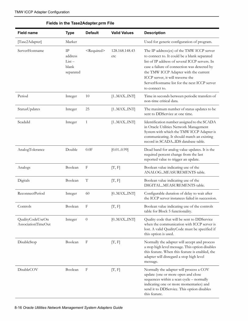
TMW ICCP Adapter Configuration
Fields in the Tase2Adapter.prm File
Field name Type Default Valid Values Description
[Tase2Adapter] Marker Used for generic configuration of program.
ServerHostname IP addressList – blankseparated
<Required> 128.168.148.43 etc
The IP address(es) of the TMW ICCP server to connect to. It could be a blank separated list of IP address of several ICCP servers. In case a failure of connection was detected by the TMW ICCP Adapter with the current ICCP server, it will traverse the ServerHostname list for the next ICCP server to connect to.
Period Integer 10 [1..MAX_INT] Time in seconds between periodic transfers of non-time critical data.
StatusUpdates Integer 25 [1..MAX_INT] The maximum number of status updates to be sent to DDService at one time.
ScadaId Integer 1 [1..MAX_INT] Identification number assigned to the SCADA in Oracle Utilities Network Management System with which the TMW ICCP Adapter is communicating. It should match an existing record in SCADA_IDS database table.
AnalogTolerance Double 0.0F [0.01..0.99] Dead band for analog value updates. It is the required percent change from the last reported value to trigger an update.
Analogs Boolean F [T, F] Boolean value indicating use of the ANALOG_MEASUREMENTS table.
Digitals Boolean T [T, F] Boolean value indicating use of the DIGITAL_MEASUREMENTS table.
ReconnectPeriod Integer 60 [0..MAX_INT] Configurable duration of delay to wait after the ICCP server instances failed in succession.
Controls Boolean F [T, F] Boolean value indicating use of the controls table for Block 5 functionality.
QualityCodeUseOnAssociationTimeOut
Integer 0 [0..MAX_INT] Quality code that will be sent to DDService when the communication with ICCP server is lost. A valid QualityCode must be specified if this option is used.
DisableStop Boolean F [T, F] Normally the adapter will accept and process a stop high level message. This option disables this feature. When this feature is enabled, the adapter will disregard a stop high level message.
DisableCOV Boolean F [T, F] Normally the adapter will process a COV update (one or more open and close sequences within a scan cycle – normally indicating one or more momentaries) and send it to DDService. This option disables this feature.
8-16 Oracle Utilities Network Management System Adapters Guide

TMW ICCP Adapter Configuration
IgnoreCritInterSysServFail Boolean F [T, F] Normally the adapter will stop if SMSserivce reports a critical service failure and not restart until services are recovered. This option disables this feature.
NoSwitchOpQualityMask Integer No Mask [0..MAX_INT] This parameter sets the quality codes that prevent switches from being operated. There is no effect on non-switch statuses.
PhaseEncodeSwitch Boolean F [T, F] If set to true, this will enable Iccp Adapter to interpret data discrete values as three-bit phase encoded statuses. [e.g., A = ‘001’, B = ‘010’, C = ‘100’, etc.]
PseudoAlarms Boolean F [T, F] If set to 1, then this will set the pseudo flag for the switch entry to be sent to DDService. Generates pseudo (advisory) alarms for ICCP reported device ops rather than actually operating the switches in the Oracle Utilities Network Management System model.
SendTimeout Integer 10 [0..MAX_INT] Timeout setting for the connection to the ICCP server.
[VCC] Marker ICCP Domain (VCC) Configuration.
Server TSEL String <Required> OSI Transport Service Access Point (TSAP) Selector of the ICCP server.
ServerSSEL String <Required> OSI Session Service Access Point (SSAP) Selector of the ICCP server.
ServerPSEL String <Required> OSI Presentation Service Access Point (PSAP) Selector of the ICCP server.
ServerAP Title String <Required> Application Process Title of the ICCP server.
ServerAEQual Integer 12 Server-side Application Entity Qualifier.
DomainName String <Required> ICCP Domain Name
TransferSets String Comma-separated list of ICCP Data Transfer Sets. Only required when using server-configured data sets.
ClientTSEL String <Required> OSI Transport Service Access Point (TSAP) Selector of the TMW ICCP Adapter.
ClientSSEL String <Required> OSI Session Service Access Point (SSAP) Selector of the TMW ICCP Adapter.
ClientPSEL String <Required> OSI Presentation Service Access Point (PSAP) Selector of the TMW ICCP Adapter.
Field name Type Default Valid Values Description
ICCP Adapter 8-17

TMW ICCP Adapter Configuration
ClientAPTitle String <Required> Application Process Title of the TMW ICCP Adapter.
ClientAEQual Integer 12 Client-side Application Entity Qualifier.
BilateralTableId String <Required> Bilateral Table Id.
Tase2Version String '2000.8' '1996.8' and '2000.8'
TASE.2 protocol version.
[ValidityQuality] Marker Assign an Oracle Utilities Network Management System quality to ICCP Validity Quality values
Valid Integer 0 2**n (n=11->31) The value is valid. This is the default (normal) value should virtually always be 0.
Held Integer 0 2**n (n=11->31) Previous data value has been held over. Interpretation is local.
Suspect Integer 0 2**n (n=11->31) Data value is questionable. Interpretation is local.
Notvalid Integer 0 2**n (n=11->31) The value is not valid.
[CurrentSourceQuality] Marker Assign an Oracle Utilities Network Management System quality to ICCP Current Source Quality values.
Telemetered Integer 0 2**n (n=11->31) Value was received from a telemetered site. This is the default (normal) value should virtually always be 0.
Calculated Integer 0 2**n (n=11->31) Value was calculated based on other data.
Entered Integer 0 2**n (n=11->31) Value was entered manually.
Estimated Integer 0 2**n (n=11->31) Value was estimated (State Estimator, etc.).
[NormalValueQuality] Marker Assign an Oracle Utilities Network Management System quality to ICCP Normal Value Quality values.
Normal Integer 0 2**n (n=11->31) The point value is that which has been configured as normal for the point. This is the default (normal) value should virtually always be 0.
Abnormal Integer 0 2**n (n=11->31) The point value is not that which has been configured as normal for the point.
[TimeStampQuality] Marker Assign an Oracle Utilities Network Management System quality to ICCP Timestamp Quality values
Valid Integer 0 2**n (n=11->31) Current value of the TimeStamp attribute contains the time stamp of when the value was last changed. This is the default (normal) value should virtually always be 0.
Field name Type Default Valid Values Description
8-18 Oracle Utilities Network Management System Adapters Guide

TMW ICCP Adapter Configuration
Configuring Data Sets in Tase2Adapter.In order for the ICCP server to be able to transfer data to NMS through the Tase2Adapter, ICCP points need to be organized into data sets. There are a few steps to achieve that:
1. Assign SCADA points to a data sets by populating the ICCP_DATA_SET column in the SCADA_MEASUREMENTS_ST table with the name of the data set.
2. Run command 'UpdateDDS -recacheMeasures' to propagate changes to the ANALOG_MEASUREMENTS and DIGITAL_MEASUREMENTS tables.
3. For each data set, add section to the Tase2Adapter configuration file. The name of the section should match the name of the data set. This section contains configuration parameters for the data set.
Data Set Configuration Parameters• Enabled
A boolean flag that enables/disables the data set.
Default: F (disabled)
• ServerConfigured
A boolean flag which indicates that this data set is configured
by the server. All configuration parameters other than Enabled are ignored for server-configured data sets.
Default: F (client-configured data set)
Tase2Adapter supports two methods of configuring transfer set parameters for data sets: client-side and server-side.
Invalid Integer 0 2**n (n=1->31) Current value of the TimeStamp attribute contains the time stamp other than when the value was last changed.
[SwitchStatusQuality] Marker Assign an Oracle Utilities Network Management System quality to the non-open/close statuses that can be returned in the two-bit ICCP status field. ICCP “open” is generally (1) and “closed” is (2).
Between Integer 262144 2**n (n=11->31) Quality code to set if the two bit ICCP switch status is reported as “between” (0).
Invalid Integer 524288 2**n (n=11->31) Quality code to set if the two bit ICCP switch status is reported as “invalid” (3).
Field name Type Default Valid Values Description
ICCP Adapter 8-19
TMW ICCP Adapter Configuration
With the client-side approach, the Tase2Adapter will create data sets and configure associated data set transfer sets during the process of connecting to the ICCP server according to the configuration parameters specified in the data set section of the configuration file.
Transfer Set Configuration Parameters• Interval
Time interval (in seconds) between TASE.2 server reports.
• TLE
Time Limit for Execution (in seconds). It is the time interval during which the TASE.2 server has to send the Data Set Transfer Report to the TASE.2 client.
• BufferTime
Time interval (in seconds) for buffering the ObjectChange condition before reporting to the TASE.2 client. The Buffer Time starts when the first ObjectChange condition occurs.
• IntegrityCheck
Time value (in seconds) for integrity check when IntegrityTimeOut condition is used.
• Critical
A boolean flag controlling type of Transfer Report acknowledgment. True means that the Transfer Report is critical and an acknowledgment from the TASE.2 client back to the TASE.2 server is expected.
• RBE
A boolean flag controlling Report By Exception mechanism. True implies that the changed objects are reported.
• AllChangesReported
A boolean flag indicating the number of changes of a given Data Value that may be reported in a single Transfer Report when RBE is true and Buffer Time is non-zero. True means all value changes within the stated buffer period are reported. False means only the last change (assuming there is more than one change of value in the buffer period) is reported in the Transfer Set.
• DSConditionsRequested
Comma-separated list of conditions to be reported by TASE.2 server.
Conditions:
IntervalTimeOut - Send a report when the Interval time arrives.
IntegrityTimeOut - Send a report of the entire data set when the Integrity Check time interval expires. This only applies when RBE is true; when RBE is false, the IntervalTimeOut can be used to send periodic reports.
ObjectChange - Send a report when any object in the data set changes.
OperatorRequest - Send a report when an operator at the TASE.2 server control center requests it.
By default all boolean flags are set to false and all integer values are set to 0.
For detailed information about TASE.2 DS Transfer Set configuration parameters, see international standard IEC 60870-6-503.
Example, data set 'ds1' is configured to report changes by exception.
[ds1]
8-20 Oracle Utilities Network Management System Adapters Guide

TMW ICCP Adapter Configuration
TLE=10RBE=TDSConditionsRequested=ObjectChangeEnabled=T
With the server-side approach, the Tase2Adapter will assume that data sets and associated transfer sets are created and configured by the ICCP server. To indicate that a data set is configured by the server, the line 'ServerConfigured=T' needs to be added to the corresponding section of the Tase2Adapter configuration file. The 'TransferSets' parameter in the [VCC] section of the configuration file needs to contain comma-separated list of the transfer sets names, which should be enabled by Tase2Adapter.
Example, data set 'ds2' and associated transfer set 'ts_ds2' are configured by the server.
[VCC]...TransferSets=ts_ds2
[ds2]ServerConfigured=TEnabled=T
ICCP Adapter 8-21

TMW ICCP Adapter Configuration
Sample Tase2Adapter.prm Configuration File[Tase2Adapter]ServerHostname=128.168.148.43Period=10ScadaId=300StatusUpdates=25Analogs=TAnalogTolerance=.001Digitals=TReconnectPeriod=60QualityCodeUseOnAssociationTimeOut=16384DisableCOV=FPhaseEncodeSwitch=TSendTimeout=30[VCC]ServerTSEL=00 23ServerSSEL=00 23ServerPSET=00 23ServerAPTitle=1,1,999,1ServerAEQual=34DomainName=NMSServerTSEL=00 24ServerSSEL=00 24ServerPSET=00 24ServerAPTitle=1,1,999,2ServerAEQual=45BilateralTableId=NMSTase2Version=2000.8 [ValidityQuality]Valid=Held=Suspect=Notvalid=1048576[CurrentSourceQuality]Telemetered=Calculated=Entered=Estimated=2097152[NormalValueQuality]Normal=Abnormal=[TimeStampQuality]Valid=Invalid=[a1]Interval=0TLE=0BufferTime=0IntegrityCheck=60Critical=FRBE=TAllChangesReported=FDSConditionsRequested=ObjectChange,IntegrityTimeOutEnabled=T
8-22 Oracle Utilities Network Management System Adapters Guide

TMW ICCP Adapter Configuration
Quality CodesThe Tase2Adapter.prm file enables ICCP quality codes to be translated into Oracle Utilities Network Management System quality codes. In the simplest (and default) configuration, all of the ICCP quality codes (except the Between and Invalid SwitchStatusQuality codes, which need to be defined to ensure proper operation) are assigned to the 'normal' Oracle Utilities Network Management System quality code (0).
Note: Oracle Utilities Network Management System quality codes are always single bit values. Therefore, the only valid value for configuration is 0 or a proper value of 2^nth power where n=0->31. The Quality Rules Table on page 8-26 table lists all the valid user-defined quality codes in Oracle Utilities Network Management System.
If none of the predefined quality codes are applicable, then a new code must be created. The following steps accomplish this:
• Choose an ICCP quality listed in the Tase2Adapter.prm.
• Check the Quality Rules Table to see which values have already been assigned to qualities.
• Assign one of the values listed below to the ICCP quality and enter it in the Quality Rules Table.
• Locate the quality in the Tase2Adapter.prm file and enter the assigned value for it.
The assigned value must be the decimal representation of 32 bits, where no more than one bit has a value of 1. For example, if the bit position is 11, use the number 2048. The following list contains the decimal values that may be assigned to new qualities: 2048, 4096, 8192, 16384, 32768, 65536, 131072, 262144, 524288, 1048576, 2097152, 4194304, 8388608, 16777216, 33554432, 67108864, 134217728, 268435456, 536870912, 1073741824, 2147483648.
Values of 0, 1, 2, 4, 8, 16, 32, 64, 128, 256, 512, 1024 may not be assigned as codes for new qualities because they are already defined and used within Oracle Utilities Network Management System. The ‘normal’ Oracle Utilities Network Management System quality code is 0.
The adapter reads the Tase2Adapter.prm file only during startup. If the quality code is added when the adapter is running, you must restart the adapter in order for it to recognize the new quality code.
ICCP Adapter 8-23

TMW ICCP Adapter Configuration
High Level MessagesThe TMW ICCP Adapter can be dynamically controlled from Oracle Utilities Network Management System by using high-level messages. They can be used any time while running the Oracle Utilities Network Management System TMW ICCP Adapter. The following high-level messages can be used:
• stop
Disconnect from the ICCP server and stop the Oracle Utilities Network Management System TMW ICCP Adapter.
• report
Empty message to determine how many Oracle Utilities Network Management System TMW ICCP Adapters are running.
• debug [on | off | #]
Turn on/off debug, or set it to a specific level. On is equivalent to 1, off is 0. Level can be any integer value no less than 0.
• debug <facility> #
Turn facility specific debug on/off. For example, to turn IA_ICCP debug on to level 3:
Action any.Tase2Adapter debug IA_ICCP 3
To turn off:
Action any.Tase2Adapter debug IA_ICCP 0
Check TMW ICCP Adapter specific log file for other facilities specific to this adapter process.
• sync
Initiates synchronization sequence. The TMW ICCP Adapter will read the latest value of each SCADA measurement from the ICCP server.
8-24 Oracle Utilities Network Management System Adapters Guide

TMW ICCP Adapter Configuration
Populating the NMS Measurements TablesICCP points must first be mapped to devices in the Oracle Utilities Network Management System model before sending SCADA updates to Oracle Utilities Network Management System. These ICCP points are placed in SCADA_MEASUREMENTS_ST table of the Oracle Utilities Network Management System database. A process needs to be formalized to create and maintain this data. This process often depends on customer specific mechanisms used to maintain the SCADA side of the ICCP interface.
Required NMS DataThe following data items are required to be populated in the NMS measurements tables:
• ICCP Point Name
• Attribute
• SCADA ID
• NMS Device Handle
• Measurement Type
• ICCP Data Set
• ICCP Data Type
ICCP Point Name• ICCP Point Name has to be unique.
• It is recommended for the name to be composed of alpha-numeric characters and underscore
• It is recommended for the first character of the ICCP Name to be a letter
• There should be no space, no periods and no dashes in the ICCP name.
Attribute• The attribute value connects a SCADA measurement to a specific device attribute in NMS.
The attribute should have a corresponding entry in the ATTRIBUTES table.
SCADA ID• SCADA system identifier. There should be a corresponding entry in the SCADA_IDS table.
NMS Device Handle• The NMS Device Handle is the handle of the device in the NMS model associated with a
particular ICCP Point. A single NMS device can have multiple ICCP points associated with it for different measurements that the SCADA system provides for the given device.
Measurement Type• Each ICCP point represents either digital (including device status) or analog measurement.
ICCP Data Set• The name of the data set this point is assigned to. Points assigned to the same data set share
the same data transfer configuration (report by exception, integrity check, etc). There can be a limit on how many points can be assigned to a single data set. Consult your ICCP server documentation.
ICCP Data Type• Each ICCP point has an associated data type. If data type is not specified for a point then the
following defaults are used:
Device status - Data_StateExtended
ICCP Adapter 8-25

TMW ICCP Adapter Configuration
Digital value - Data_DiscreteQ
Analog value - Data_RealQ
Information Model - Database Schema
Quality Rules TableThis database table will define the quality codes that may be used for analog and digital values. This table defines the meaning of each bit in the quality codes for SCADA measurements.
Note: If multiple bits in the quality code are set, then the color of the measurement text in the Viewer is determined by the color of the lowest order bit that is set in the quality code.
Column Name Data Type Size Description Values
PRIORITY NUMBER Ranking priority of the quality code Priority code, specifies relative importance of this quality bit over other quality bits
VALUE NUMBER Bit value used for the quality code change.
For Phase 1:2048=No Data4096=Old Data
STRING VARCHAR2 3 Description of the quality code, which is displayed next to the value of the measurement when a quality exists for a measurement change.
The actual character string displayed next to the device when viewed via the Viewer
DESCRIPTION VARCHAR2 128 Descriptive string Any text string-usually the action taken from the SCADA Summary
COLOR NUMBER Designates which color is used in the Viewer to display the measurement when a particular quality bit is set. Integer value for the color associated to the quality code change to be displayed
The integers are mapped to the pre-allocated colors documented in separate application file.
LOCATION NUMBER Location of symbol in relation to the device associated with the value.only used if a symbol is defined for the quality code as opposed to just a color for a quality change
1-9; 5 overrides the device symbol
SYMBOL NUMBER The symbol used to display the value. only used if a symbol is defined for the quality code as opposed to just a color for a quality change
Valid Symbol Identification Number defined in <project>_SYMBOLS.sym. 0 if defining a text symbol.
OFF_NOMINAL VARCHAR2 1 Whether or not the value is off-nominal
Y or N
8-26 Oracle Utilities Network Management System Adapters Guide

TMW ICCP Adapter Configuration
SCADA Measurements TableThe SCADA_MEASUREMENTS_ST table defines digital and analog measurements as used by Oracle Utilities Network Management System. It is a staging table used by DDService for populating the production SCADA measurements tables (ANALOG_MEASUREMENTS and DIGITAL_MEASUREMENTS).
The Oracle Utilities Network Management System ICCP Adapter communicates dynamic information to the Oracle Utilities Network Management System services. The services will cache measurements defined by this table. Population is dependent upon customer-supplied information.
Column Name Data Type Size Description Values
MEASUREMENT_TYPE
VARCHAR2 1 Measurement type code. A (analog)D (digital)
H_CLS NUMBER Class component of handle Valid object class
H_IDX NUMBER Index component of handle >0
PARTITION NUMBER Partition number, index component of partition handle
Valid partition or 0 for multi-partition objects
ATTRIBUTE NUMBER Attribute number which identifies measurement type
Valid attribute number
TTL NUMBER Setting for displaying measurement value in the Viewer or not.
1 or 0. 1=yes
LIMIT_GROUP_ID NUMBER Limit group ID Customer defined
RTI_ALIAS VARCHAR2 128 ICCP Point Name Alphanumeric
SCADA_ID NUMBER SCADA host ID Foreign key into SCADA_IDS database table.
RTU_ID VARCHAR2 32 SCADA RTU ID String (optional)
QUALITY NUMBER Measurement quality code Bit mask of quality codes
VALUE NUMBER Measurement/entered value Entered value
UPDATE_FLAG NUMBER Manual replace flag 1=true, 0=false
ICCP Adapter 8-27

TMW ICCP Adapter Configuration
ICCP_OBJECT VARCHAR2 32 ICCP data type for this measurement
List of the supported ICCP data types:
Data_Discrete
Data_DiscreteQ
Data_DiscreteQTimeTag
Data_DiscreteExtended
Data_Real
Data_RealQ
Data_RealQTimeTag
Data_RealExtended
Data_StateQ
Data_StateQTimeTag
Data_StateExtended
ICCP_DATA_SET VARCHAR2 64 Name of the ICCP data set this measurement is assigned to.
String
DISPLAY_ID VARCHAR2 64
NORMAL_STATE NUMBER
CONTROLLABLE VARCHAR2 1
ACTIVE VARCHAR2 1 Active flag for patch management, indicates whether the row is active within the model
Y(yes=active), N(no=inactive), A(local add=active), D(local delete=inactive), R(locally removed, dependent=inactive)
SOURCE VARCHAR2 33 Source of the measurement. any character string.
OFF_NOMINAL_TIME
DATE
Column Name Data Type Size Description Values
8-28 Oracle Utilities Network Management System Adapters Guide

TMW ICCP Adapter Configuration
SCADA_IDSSCADA_IDS contains information about known SCADA systems that NMS is connected to. The TMW ICCP Adapter needs to have an entry in this table.
Column Name Data Type Size Description Values
ID NUMBER SCADA system id
SCADA_NAME VARCHAR2 32 SCADA system name
ADAPTER_TYPE VARCHAR2 32 Adapter used to communicate with the SCADA system
MULTISPEAK (MultiSpeak SCADA Adapter)RTADAPTER (Generic SCADA Adapter)ICCP (ICCP Adapter)
ACTIVE VARCHAR2 1 Active flag Y - activeN - inactive
ICCP Adapter 8-29

TMW ICCP Adapter Configuration
8-30 Oracle Utilities Network Management System Adapters Guide

Chapter 9Specific SCADA Adapters
This chapter includes the following topics:
• OSI SCADA Adapter
OSI SCADA AdapterThe OSI SCADA Adapter requires the scada_osi license in your <project>_licensed_products.dat file. Example configuration for the OSI SCADA Adapter is found in the multispeak_scada_config.sql template file. It includes the following concepts:
• General Configuration Parameters
• Point List Configuration
• Real-Time States/Values
• Tags
General Configuration ParametersThe SCADA_LINKS table requires that the MultiSpeak SCADA Server URL be configured. For example:
INSERT INTO scada_links (id, scada_id, ws_url, priority, active)VALUES (1, 200, 'http://osi-scada-server:8080/axis2/services/MultiSpeak_v41_SCADA_Server', 1, 'Y');
The CES_PARAMETERS SoapUI.plugin_class should be the OSI MultiSpeak plug-in class. For example:
INSERT INTO ces_parameters (app, attrib, value)VALUES ('SCADAInterface', 'SoapUI.plugin_class','com.splwg.oms.interfaces.scada.plugins.OsiScada');
Specific SCADA Adapters 9-1
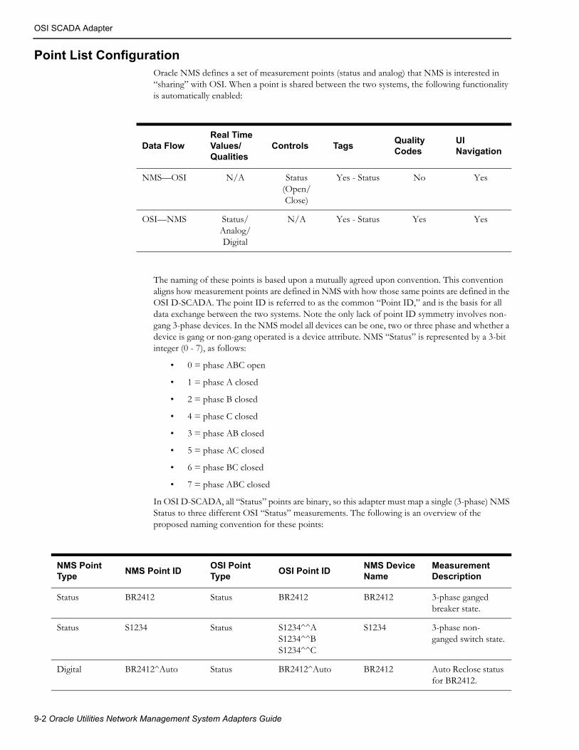
OSI SCADA Adapter
Point List ConfigurationOracle NMS defines a set of measurement points (status and analog) that NMS is interested in “sharing” with OSI. When a point is shared between the two systems, the following functionality is automatically enabled:
The naming of these points is based upon a mutually agreed upon convention. This convention aligns how measurement points are defined in NMS with how those same points are defined in the OSI D-SCADA. The point ID is referred to as the common “Point ID,” and is the basis for all data exchange between the two systems. Note the only lack of point ID symmetry involves non-gang 3-phase devices. In the NMS model all devices can be one, two or three phase and whether a device is gang or non-gang operated is a device attribute. NMS “Status” is represented by a 3-bit integer (0 - 7), as follows:
• 0 = phase ABC open
• 1 = phase A closed
• 2 = phase B closed
• 4 = phase C closed
• 3 = phase AB closed
• 5 = phase AC closed
• 6 = phase BC closed
• 7 = phase ABC closed
In OSI D-SCADA, all “Status” points are binary, so this adapter must map a single (3-phase) NMS Status to three different OSI “Status” measurements. The following is an overview of the proposed naming convention for these points:
Data FlowReal Time Values/ Qualities
Controls TagsQuality Codes
UI Navigation
NMS—OSI N/A Status (Open/Close)
Yes - Status No Yes
OSI—NMS Status/Analog/Digital
N/A Yes - Status Yes Yes
NMS Point Type
NMS Point IDOSI Point Type
OSI Point IDNMS Device Name
Measurement Description
Status BR2412 Status BR2412 BR2412 3-phase ganged breaker state.
Status S1234 Status S1234^^AS1234^^BS1234^^C
S1234 3-phase non-ganged switch state.
Digital BR2412^Auto Status BR2412^Auto BR2412 Auto Reclose status for BR2412.
9-2 Oracle Utilities Network Management System Adapters Guide

OSI SCADA Adapter
There is some flexibility regarding how this common Point ID is defined in the D-SCADA system. For example, the OSI SCADA point “Name” field could be used to store the common ID used by Oracle NMS, or a combination of OSI SCADA fields could also be used. This allows for an “automatic” mapping to telemetry in the OSI system without the user having to maintain a separate mapping table.
The OSI D-SCADA system can be configured to periodically perform this synchronization with Oracle NMS.
Real-Time States/ValuesOSI provides a one-way notification of changes to subscribed status and analog points, as defined by the Oracle NMS shared point list. Attributes included in this payload include state/value, quality, trip count (for status), and time stamp. In the case of quality, a set of quality types has been agreed upon for the lexicon used between the Oracle NMS and OSI systems (see table below), with each system mapping their internal quality types to these intermediate qualities. The lexicon used is limited to the qualities supported in the MultiSpeak v4.1 standard, which includes Measured, Default, Estimated, Calculated, Initial, Last, and Failed.
A change in any of the attributes that make up the point will trigger an immediate notification to the NMS with all of the current attributes for that point within 5 seconds from when the change occurred.
In addition to the change-based notification, NMS will retrieve all of the status and analog point data from OSI when it first initializes or when NMS has detected that the OSI system has recovered from an event that could have caused change-based notifications to be missed (for example, system failover, database build, and so forth).
Analog BR2412^Amps_ABR2412^Amps_BBR2412^Amps_C
Analog BR2412^Amps_ABR2412^Amps_BBR2412^Amps_C
BR2412 3-phase ganged breaker current measurement (in Amps).
Analog S3113^fault_kv_aS3113^fault_kv_bS3113^fault_kv_c
Analog S3113^fault_kv_aS3113^fault_kv_bS3113^fault_kv_c
S3113 3-phase non-ganged switch fault voltage (in kV).
NMS Point Type
NMS Point IDOSI Point Type
OSI Point IDNMS Device Name
Measurement Description
MultiSpeak Quality Description
Measured Default quality for any OSI D-SCADA telemetered points.
Calculated Default quality for any calculated (i.e., OSI “C_*”) D-SCADA points.
Last Indicates presence of a Scan Inhibit tag on the OSI D-SCADA point.
Failed Indicates non-update quality on the OSI D-SCADA point.
Specific SCADA Adapters 9-3
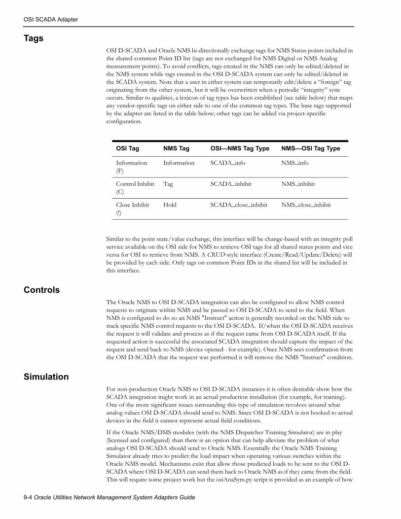
OSI SCADA Adapter
TagsOSI D-SCADA and Oracle NMS bi-directionally exchange tags for NMS Status points included in the shared common Point ID list (tags are not exchanged for NMS Digital or NMS Analog measurement points). To avoid conflicts, tags created in the NMS can only be edited/deleted in the NMS system while tags created in the OSI D-SCADA system can only be edited/deleted in the SCADA system. Note that a user in either system can temporarily edit/delete a “foreign” tag originating from the other system, but it will be overwritten when a periodic “integrity” sync occurs. Similar to qualities, a lexicon of tag types has been established (see table below) that maps any vendor-specific tags on either side to one of the common tag types. The base tags supported by the adapter are listed in the table below; other tags can be added via project-specific configuration.
Similar to the point state/value exchange, this interface will be change-based with an integrity poll service available on the OSI side for NMS to retrieve OSI tags for all shared status points and vice versa for OSI to retrieve from NMS. A CRUD-style interface (Create/Read/Update/Delete) will be provided by each side. Only tags on common Point IDs in the shared list will be included in this interface.
ControlsThe Oracle NMS to OSI D-SCADA integration can also be configured to allow NMS control requests to originate within NMS and be passed to OSI D-SCADA to send to the field. When NMS is configured to do so an NMS "Instruct" action is generally recorded on the NMS side to track specific NMS control requests to the OSI D-SCADA. If/when the OSI D-SCADA receives the request it will validate and process as if the request came from OSI D-SCADA itself. If the requested action is successful the associated SCADA integration should capture the impact of the request and send back to NMS (device opened - for example). Once NMS sees confirmation from the OSI D-SCADA that the request was performed it will remove the NMS "Instruct" condition.
SimulationFor non-production Oracle NMS to OSI D-SCADA instances it is often desirable show how the SCADA integration might work in an actual production installation (for example, for training). One of the more significant issues surrounding this type of simulation revolves around what analog values OSI D-SCADA should send to NMS. Since OSI D-SCADA is not hooked to actual devices in the field it cannot represent actual field conditions.
If the Oracle NMS/DMS modules (with the NMS Dispatcher Training Simulator) are in play (licensed and configured) than there is an option that can help alleviate the problem of what analogs OSI D-SCADA should send to Oracle NMS. Essentially the Oracle NMS Training Simulator already tries to predict the load impact when operating various switches within the Oracle NMS model. Mechanisms exist that allow those predicted loads to be sent to the OSI D-SCADA where OSI D-SCADA can send them back to Oracle NMS as if they came from the field. This will require some project work but the osiAnaSym.py script is provided as an example of how
OSI Tag NMS Tag OSI—NMS Tag Type NMS—OSI Tag Type
Information (F)
Information SCADA_info NMS_info
Control Inhibit (C)
Tag SCADA_inhibit NMS_inhibit
Close Inhibit (!)
Hold SCADA_close_inhibit NMS_close_inhibit
9-4 Oracle Utilities Network Management System Adapters Guide

OSI SCADA Adapter
to propagate Oracle NMS values to OSI D-SCADA. The nms-osi-ana-sim script can be used to help manage an Oracle NMS daemon process via Oracle NMS SMService. Contact your Oracle project deployment team and/or Oracle support for more information.
NavigationIt is possible to support direct Oracle NMS Java client navigation to/from an OSI D-SCADA client. This is handled outside of the MultiSpeak adapter - via a pair of named pipes on the workstation supporting both the Oracle NMS Java Swing client and the OSI D-SCADA client. Setup/configuration for this type of navigation is project specific and beyond the scope of this document. It is merely mentioned here. Contact your Oracle project deployment team and/or Oracle support for more information.
Specific SCADA Adapters 9-5

OSI SCADA Adapter
9-6 Oracle Utilities Network Management System Adapters Guide

Chapter 10SCADA Calculation Engine
This chapter includes the following topics:
• Introduction
• SCADA Calculation Engine Database Configuration
• SCADA Calculation Engine SRS Rules Configuration
Introduction
The Oracle Utilities Network Management System SCADA Calculation Engine generates calculated point values based on measurements received from any supported SCADA Adapter. These measurement values, which are fully configurable using SQL procedures, are fed into the system using the RTDBAdapter (RTAdapter with the -dir RDBMS option).
The executable program (CalcAdapter) can be configured in the system.dat file.
SCADA Calculation Engine Database ConfigurationThe SCADA_CALC_FUNC table holds the calculation engine configuration mapping. Insert into this table the specific rti_alias point names and functions to call for each mapping needed. Alternately, if your rti_alias point names follow the standard <device_alias>-<attribute name> convention, you can use [ALL], which creates this mapping for every device that has these measurements.
Column Description
seq_id The generated primary key from the scada_calc_seq sequence.
rti_alias The point name to update.
unc_name The function to call. NMS provides many examples in the scadacalc package.
func_args The arguments to the function. Put single quotes around strings, like point names.
SCADA Calculation Engine 10-1
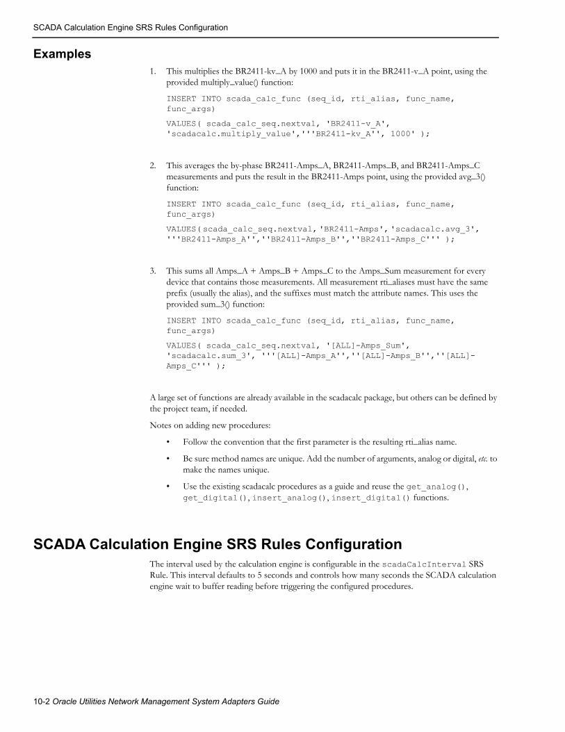
SCADA Calculation Engine SRS Rules Configuration
Examples1. This multiplies the BR2411-kv_A by 1000 and puts it in the BR2411-v_A point, using the
provided multiply_value() function:
INSERT INTO scada_calc_func (seq_id, rti_alias, func_name, func_args)
VALUES( scada_calc_seq.nextval, 'BR2411-v_A', 'scadacalc.multiply_value','''BR2411-kv_A'', 1000' );
2. This averages the by-phase BR2411-Amps_A, BR2411-Amps_B, and BR2411-Amps_C measurements and puts the result in the BR2411-Amps point, using the provided avg_3() function:
INSERT INTO scada_calc_func (seq_id, rti_alias, func_name, func_args)
VALUES( scada_calc_seq.nextval, 'BR2411-Amps', 'scadacalc.avg_3', '''BR2411-Amps_A'',''BR2411-Amps_B'',''BR2411-Amps_C''' );
3. This sums all Amps_A + Amps_B + Amps_C to the Amps_Sum measurement for every device that contains those measurements. All measurement rti_aliases must have the same prefix (usually the alias), and the suffixes must match the attribute names. This uses the provided sum_3() function:
INSERT INTO scada_calc_func (seq_id, rti_alias, func_name, func_args)
VALUES( scada_calc_seq.nextval, '[ALL]-Amps_Sum', 'scadacalc.sum_3', '''[ALL]-Amps_A'',''[ALL]-Amps_B'',''[ALL]-Amps_C''' );
A large set of functions are already available in the scadacalc package, but others can be defined by the project team, if needed.
Notes on adding new procedures:
• Follow the convention that the first parameter is the resulting rti_alias name.
• Be sure method names are unique. Add the number of arguments, analog or digital, etc. to make the names unique.
• Use the existing scadacalc procedures as a guide and reuse the get_analog(), get_digital(), insert_analog(), insert_digital() functions.
SCADA Calculation Engine SRS Rules ConfigurationThe interval used by the calculation engine is configurable in the scadaCalcInterval SRS Rule. This interval defaults to 5 seconds and controls how many seconds the SCADA calculation engine wait to buffer reading before triggering the configured procedures.
10-2 Oracle Utilities Network Management System Adapters Guide

Chapter 11MultiSpeak Adapter
This chapter includes the following topics:
• Introduction
• Installation
• Software Configuration
• Adapter Interface Communication Overview
• Adapter Design
• Database Schema
• SCADA Component
• ]Supported Data Flows
• Software Configuration
• Plugin Support
• High-Level Messages
• Troubleshooting
IntroductionThe Oracle Utilities Network Management System MultiSpeak Adapter provides the ability to request and receive meter status information from an Automated Meter Reading (AMR) system, to receive crew location information from an Automated Vehicle Location (AVL) system, and to communicate with SCADA systems. The interface uses communication protocols as defined in MultiSpeak Version 4.1 Web Services specification. (SOAP protocol version 1.1 is used unless otherwise noted.) HTTP/HTTPS protocol is used as transport mechanism. It allows Oracle Utilities Network Management System to communicate securely with any MultiSpeak-compliant AMR, AVL, or SCADA system. In addition to HTTP/HTTPS, communication can be done over JMS.
The Oracle Utilities Network Management System MultiSpeak Adapter is implemented as a Java application, running on the Oracle WebLogic Server platform. The URL for accessing web services deployed by the Oracle Utilities Network Management System MultiSpeak Adapter differs depending on the SOAP version that is used by the client.
MultiSpeak Adapter 11-1

Installation
Please read through this chapter thoroughly before beginning your product installation.
Installation• Installation Overview
• Adapter Installation Instructions for Oracle WebLogic Server
• JMS Transport Mechanism
Note: The installation instructions that follow assume that the Oracle Utilities Network Management System Web Gateway component has been installed. Refer to the Oracle Utilities Network Management System Installation Guide for complete instructions.
Installation OverviewThe Oracle Utilities Network Management System MultiSpeak Adapter is delivered as five files:
• $CES_HOME/dist/install/nms-multispeak.ear.base: NMS Multispeak adapter application.
• $CES_HOME/sdk/java/lib/multispeak-4.1.0.jar: Java classes generated from MultiSpeak 4.1.0 WSDLs.
• $CES_HOME/sdk/java/lib/nms-multispeak-sdk-1.12.0.1.0.jar: Java classes needed to build custom plugins.
• $CES_HOME/sdk/java/docs/nms-multispeak-docs.zip: Documentation (javadoc) for classes included into multispeak-4.1.0.jar and nms-multispeak-sdk-1.12.0.1.0.jar archives.
• $CES_HOME/sdk/java/samples/nms-multispeak-plugins.zip: Java project, which can be used as a starting point for building custom plugins for SCADA components of the NMS MultiSpeak adapter.
The nms-install-config script is used to apply adapter configuration changes and create the nms-multispeak.ear file, which can be deployed to the Oracle WebLogic Server (see Software Configuration on page 11-8 for configuration instructions).
Deploying the nms-multspeak.ear file on the same server as the cesejb.ear file is not supported; however, both managed servers do need to be in the same Oracle WebLogic Server domain.
SOAP Version URL
1.1 https://<host name>:<port>/nms-ms/oa
1.2 https://<host name>:<port>/nms-ms/oa12
11-2 Oracle Utilities Network Management System Adapters Guide

Installation
Adapter Installation Instructions for Oracle WebLogic ServerTopics
• Create a Managed Server (Optional)
• Configure Data Source for the Adapters Managed Server
• Deploy the Adapter
Create a Managed Server (Optional)To simplify creation of a new managed server, you may clone an existing Oracle Utilities Network Management System managed server.
1. Log in to the WebLogic Server Administration Console.
Note: The URL for WebLogic will be http://hostname:port/console where hostname represents the DNS name or IP address of the Administration Server, and port represents the number of the port on which the Administration Server is listening for requests (port 7001 by default).
2. Click Lock & Edit.
3. In the Domain Structure tree, expand Environment, then select Servers to open the Summary of Servers page.
4. Select an Oracle Utilities Network Management System server in the Servers table and click Clone.
5. Click the link to the cloned server, select the General tab, change the Listen Port and SSL Listen Port to unique values.
Configure Data Source for the Adapters Managed ServerYou may configure a new JDBC data source or add the adapter managed server as a target to an existing Oracle Utilities Network Management System read/write data source.
Note: See “Configure Database Connectivity” in the Oracle Utilities Network Management System Installation Guide for information on creating JDBC data sources.
1. In the Domain Structure tree, expand Services, then select Data Sources.
2. In the Data Sources table, click the data source name (either a new data source or an existing read/write NMS data source) to open the Settings for JDBC_Data_Source_Name page.
3. Select the Targets tab.
4. Add the adapter managed server to the list of targets.
5. Click Save.
Enabling Support for Plain HTTPBy default the adapter is configured to only accept incoming requests over HTTPS. To enable support for plain HTTP, add or uncomment the line in $NMS_CONFIG/jconfig/build.properties file:
option.no_multispeak_force_https
Then build new nms-multispeak.ear by running:
nms-install-config --java
MultiSpeak Adapter 11-3

Installation
Authentication MethodsBy default the adapter is configured to use Basic HTTP Authentication for incoming web service requests. If credentials from the MultiSpeak message header should be used instead, add or uncomment the line in $NMS_CONFIG/jconfig/build.properties file:
option.no_multispeak_http_auth
Then build new nms-multispeak.ear by running:
nms-install-config --java
Notes:
• This parameter has no effect on JMS transport mechanism. It cannot use Basic HTTP Authentication mechanism.
• When Basic HTTP Authentication is not used, the configuration parameter “config.message_credentials_required” allows skipping authentication when credentials are not present in the message.
The adapter authorizes incoming web service requests by checking that caller that has the ‘NmsWrite’ role in WebLogic Server..
Deploy the Adapter1. In the left pane of the Administration Console, select Deployments.
2. In the right pane, click Install.
3. In the Install Application Assistant, locate the nms-multispeak.ear file.
4. Click Next.
5. Select Install this deployment as an application.
6. Click Next.
7. Select the servers and/or clusters to which you want to deploy the application.
Note: If you have not created additional Managed Servers or clusters, you will not see this assistant page.
8. Click Next.
9. Set the deployed name of the application to: nms-multispeak.
10. Click Next.
11. Review the configuration settings you have specified.
12. Click Finish to complete the installation.
11-4 Oracle Utilities Network Management System Adapters Guide

Installation
Clustered DeploymentWhen MultiSpeak Adapter is deployed on a WebLogic cluster, the web service front end is active on all cluster nodes. However, the node that processes a request differs for different components of the Adapter.
For AVL components the node which received the request will process it, which balances the load between the cluster nodes.
For AMR and SCADA components there is a single "active" node that does the processing. All requests received by different nodes are forwarded to the "active" node. If the "active" node fails one of the remaining nodes will become "active" automatically. When this happens the AMR and SCADA adapter components will go through an initialization process on the node that has become "active". For the SCADA component this also means that it will start a new synchronization sequence with the SCADA system(s).
Note: clustered deployment assumes that there is a software or hardware load balancer present to direct incoming web service request to different nodes of the cluster.
JMS Transport Mechanism• The JMS transport mechanism is based on the SOAP over JMS specification.
• Two JMS queues are used per communication channel (one for requests and another for responses) to simulate synchronous communication.
• Each individual request is synchronous. The system places the message on the request queue and waits for a reply to arrive on the response queue.
• TextMessage or BytesMessage JMS message classes can be used. In both cases message must be a valid MultiSpeak message.
• Requests and responses are connected through JMSCorrelationID JMS header.
• In the request message, the JMS header JMSReplyTo must contain the queue where response message should be sent.
• SOAP protocol versions 1.1 and 1.2 are supported.
• There is no support for accessing a WSDL over JMS.
The following table describes how JMS message properties, specific to SOAP over JMS, are being used:
JMS Message Property Value
SOAPJMS_binding Version “1.0”
SOAPJMS_targetService “SCADA_Server”, "OD_Server" or “OA_Server” depending on the target system
SOAPJMS_soapAction SOAP action
SOAPJMS_contentType "text/xml; charset="utf-8""
SOAPJMS_isFault “true” for SOAP fault messages
MultiSpeak Adapter 11-5

Installation
Configuring JMS Support
Incoming Data FlowsSupport for accepting incoming requests over JMS in NMS MultiSpeak adapter is controlled by changing value of the config.multispeak_jms property in $NMS_CONFIG/jconfig/build.properties file.
Possible values:
• none: JMS support is disabled
• single: single JMS queue for all incoming data flows
• scada: separate JMS queue for each incoming SCADA data flow (for backward compatibility value 'multiple' has the same effect as 'scada')
• amr: separate JMS queue for each incoming AMR data flow
• avl: separate JMS queue for each incoming AVL data flow
Note: 'scada', 'amr', and 'avl' can be specified together.
By default JMS support is disabled.
After modifying the $NMS_CONFIG/jconfig/build.properties file, regenerate the nms-multispeak.ear with the new configuration by executing:
nms-install-config -–java
JNDI names of JMS connection factory and queue(s) used for incoming data flows are fixed.
Connection Factorynms-amr/ConnectionFactory
QueuesSingle Queue Mode
In single queue mode, all incoming requests are sent to the same JMS queue: nms-amr/queue/OA.
Multiple Queues Mode
When multiple incoming queues are used each incoming MultiSpeak data flow uses its own JMS queue.
List of JMS queues and associated MultiSpeak operations:
• nms-amr/queue/OAPingURL
PingURL
• nms-amr/queue/OAGetMethods
GetMethods
• nms-amr/queue/OAStatusChangedNotificationByPointID
SCADAStatusChangedNotification
SCADAStatusChangedNotificationByPointID
• nms-amr/queue/OAStatusChangedNotificationByPointIDSync
StatusChangedNotificationByPointID
• nms-amr/queue/OAAnalogChangedNotificationByPointID
SCADAAnalogChangedNotification
SCADAAnalogChangedNotificationByPointID
11-6 Oracle Utilities Network Management System Adapters Guide
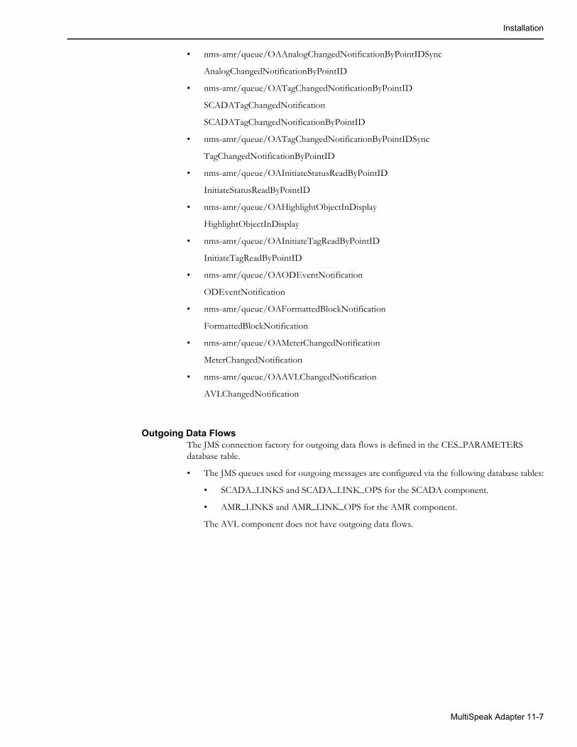
Installation
• nms-amr/queue/OAAnalogChangedNotificationByPointIDSync
AnalogChangedNotificationByPointID
• nms-amr/queue/OATagChangedNotificationByPointID
SCADATagChangedNotification
SCADATagChangedNotificationByPointID
• nms-amr/queue/OATagChangedNotificationByPointIDSync
TagChangedNotificationByPointID
• nms-amr/queue/OAInitiateStatusReadByPointID
InitiateStatusReadByPointID
• nms-amr/queue/OAHighlightObjectInDisplay
HighlightObjectInDisplay
• nms-amr/queue/OAInitiateTagReadByPointID
InitiateTagReadByPointID
• nms-amr/queue/OAODEventNotification
ODEventNotification
• nms-amr/queue/OAFormattedBlockNotification
FormattedBlockNotification
• nms-amr/queue/OAMeterChangedNotification
MeterChangedNotification
• nms-amr/queue/OAAVLChangedNotification
AVLChangedNotification
Outgoing Data FlowsThe JMS connection factory for outgoing data flows is defined in the CES_PARAMETERS database table.
• The JMS queues used for outgoing messages are configured via the following database tables:
• SCADA_LINKS and SCADA_LINK_OPS for the SCADA component.
• AMR_LINKS and AMR_LINK_OPS for the AMR component.
The AVL component does not have outgoing data flows.
MultiSpeak Adapter 11-7

Software Configuration
Software ConfigurationConfiguration for the AMR and AVL components of the Oracle Utilities Network Management System MultiSpeak Adapter comes from the following sources:
• CES_PARAMETERS database table
• Oracle Utilities Network Management System Configuration Rules
Support for Encrypted Configuration ParametersSome configuration parameters that are stored in the CES_PARAMETERS database table contain sensitive information, such as authentication credentials, which should be protected. To protect this data, the VALUES column can be encrypted using Oracle WebLogic Server encrypt utility. This utility encrypts cleartext strings for use with Oracle WebLogic Server. Its output can then be used to populate values in CES_PARAMETERS database table.
For detailed information see “encrypt” in the Oracle WebLogic Server Command Reference.
AMR Configuration ParametersEntries in the CES_PARAMETERS database table for the AMR component of the Oracle Utilities Network Management System MultiSpeak Adapter should have value 'AMRInterface' in the APP column. Column ATTRIB should contain name of the configuration parameter and column VALUE its value.
The following table describes the general configuration parameters.
Parameter Description
config.credentials Absolute path to the file containing user credentials the adapter will use to communicate with Oracle Utilities Network Management System. Either this parameter or both config.username and config.password parameters should be provided. If all are present, then the config.username/config.password pair is used.
config.username Valid NMS username, which has the ‘NmsService’ role in WebLogic Server.
config.password NMS user password. Value of this parameter should be encrypted.
11-8 Oracle Utilities Network Management System Adapters Guide

Software Configuration
config.nms_url URL for accessing Oracle Utilities Network Management System. If this parameter is not provided then it is assumed that MultiSpeak Adapter is deployed on the same Managed Server as cesejb.ear.This parameter is specified for each component of the adapter, but only one value is actually used; all components will connect to the same NMS instance. The value is taken from the first enabled component according to the following order of precedence:1. SCADA
2. AMR
3. AVL
Note: This parameter replaces the Foreign JNDI configuration used in earlier versions of the Adapter.
config.message_credentials_required
If this parameter is set to false then credentials for authenticating with NMS are taken from the MultiSpeak header of the incoming message. If this parameter is set to false and credentials are not present in the MultiSpeak header of the incoming message then username and password configured in the adapter is used to authenticate with NMS.
Valid Values: true|false. Default: true
config.amr_vendor AMR vendor.Supported AMR vendors:• multispeak: MultiSpeak-compliant AMR system.
This parameter is required.
Default: multispeak
config.ping_request_interval Time interval in seconds between subsequent meter ping requests to the AMR system.
Default: 60 seconds
config.enabled Enables AMR processing.
Default: false
config.unsolicited_message_deadband
Deadband value in seconds for unsolicited messages reporting same status for a meter. If several unsolicited messages of the same type are received within the deadband then only one of them will be processed.
Default: 60 seconds
config.max_meter_status_age Period of time in seconds after which meter status information received from AMR system is considered stale and has to be obtained from the AMR system again.
Default: 300 seconds
Parameter Description
MultiSpeak Adapter 11-9

Software Configuration
config.max_ping_request_age If difference between the current time and ping request time is greater than value of this parameter then the request is too old to be sent to the AMR system. Such requests are marked as completed in the AMR_RESPONSES table. The value is defined in seconds.
Default: 3600 seconds
config.max_ping_response_age If the difference between current time and the unsolicited ping response time is greater than value of this property, then the response is too old to be sent to the NMS. Such responses are removed from the AMR_RESPONSES table.
Default: 3600 seconds
config.max_responses_per_msg Maximum number of meter ping responses to be sent to NMS in a single message. The allowed range for this parameter is [100...10000].
Default: 1000
config.ws_request_timeout Timeout (in seconds) for web service requests to the AMR system. Request will fails if AMR system does not respond before the timeout expires.
Default: 30 seconds
config.max_pings_per_cycle Maximum number of meter ping requests to be processed in one cycle (cycle duration is defined by the config.ping_request_interval parameter).
Default: 10000
config.bellwether_read_interval Reading interval for bellwether meters in seconds.
Default: 900 seconds
config.bellwether_query_type Query type for periodic read of bellwether meters.The query type defines the list of values to be read from meters (see the multispeak.query_type parameter on page 11-14 for details).
Supported Query Types:• voltage: query voltage at the meter
config.bellwether_scada_name Name of the entry in the SCADA_IDS table to be used to report measurements read from bellwether meters. The measurements are reported through the SCADA component of this adapter so the entry in the SCADA_IDS table must have the ADAPTER_TYPE "MULTISPEAK".
Default: AMR
Parameter Description
11-10 Oracle Utilities Network Management System Adapters Guide

Software Configuration
config.use_voltage_ping Use meter voltage read instead of meter ping to determine meter status.Received voltage is compared against configured low voltage threshold value. A voltage value lower than the threshold is interpreted as the meter not having power. For multi-phase meters, voltage on any phase being below threshold means that the meter has no power.
Supported Options:• always: always use voltage read
• multiphase: only use voltage read for multiphase meters
• never: never use voltage read
Default: never.
config.voltage_query_type Query type for generic (single phase) meter voltage read.When using voltage read to determine meter status, this query type is used for single phase meters. The query type defines the list of values to be read from meters (see the multispeak.query_type parameter 11-14 for details).
config.phase_voltage_query_type Query type for reading voltage value of the individual meter phases. When using voltage read to determine meter status this query type is used for multiphase meters. The query type defines the list of values to be read from meters (see the multispeak.query_type parameter 11-14 for details).
config.multiphase_meter Comma-separated list of possible values of the AMR_CU_METERS.METER_PHASES column that indicate a multiphase meter.
config.allow_update_non_amr Allows meter updates to be processed for meters that are not marked as AMR-enabled. This is only applicable to the incoming MeterChangedNotification messages.
Default: false
config.ignore_unknown_meter_statuses
If enabled, then received meter status updates that correspond to the UNKNOWN meter status will be ignored. Otherwise such meter status updates will be recorded in the AMR_CU_METERS and AMR_CU_METERS_HISTORY tables.
Note: UNKNOWN meter status will not be used to satisfy pending meter status requests; the system will attempt to ping the meter again until it receives an ON or OFF response or the configured number of attempts is exhausted.
Default: true (enabled)
Parameter Description
MultiSpeak Adapter 11-11

Software Configuration
The following table describes configuration parameters specific to a particular AMR vendor. This could be any MultiSpeak-compliant AMR system.
config.write_power_offs_to_db If set to 'true', the adapter will write unsolicited meter power-off messages received from the AMR/AMI system into the AMR_POWER_OFFS table instead of delivering them to JMService.Default: false
Parameter Description
multispeak.meter_status.<external status>
This parameter configures mapping between external (MultiSpeak) and internal meter status values.
Valid Values:• ON: meter is energized
• OFF: meter is deenergized
• UNKNOWN: external meter status has no configured mapping.
Examples:multispeak.meter_status.Outage=OFF multispeak.meter_status.PowerOff=OFF multispeak.meter_status.PowerOn=ON multispeak.meter_status.Restoration=ONmultispeak.meter_status.Instantaneous=UNKNOWN multispeak.meter_status.NoResponse=UNKNOWN multispeak.meter_status.Inferred=UNKNOWN
multispeak.od_oa.url This parameter configures the URL of the AMR system web service.
Default: https://localhost/multispeak
multispeak.od_oa.username Username to use when connecting to the AMR system web service.
Default: empty string
multispeak.od_oa.password Password to use when connecting to the AMR system web service.
Default: empty string
multispeak.od_oa.header.<attribute>
Used to set the values for MultiSpeak header attributes. For example, the following would set the MultiSpeak header attribute 'Company' to the value 'Oracle':
multispeak.od_oa.header.Company=Oracle
Parameter Description
11-12 Oracle Utilities Network Management System Adapters Guide
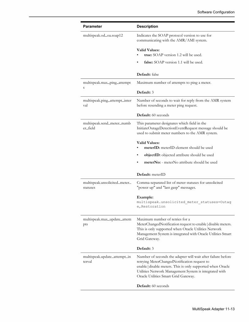
Software Configuration
multispeak.od_oa.soap12 Indicates the SOAP protocol version to use for communicating with the AMR/AMI system.
Valid Values:• true: SOAP version 1.2 will be used.
• false: SOAP version 1.1 will be used.
Default: false
multispeak.max_ping_attempts
Maximum number of attempts to ping a meter.
Default: 3
multispeak.ping_attempt_interval
Number of seconds to wait for reply from the AMR system before resending a meter ping request.
Default: 60 seconds
multispeak.send_meter_number_field
This parameter designates which field in the InitiateOutageDetectionEventRequest message should be used to submit meter numbers to the AMR system.
Valid Values:• meterID: meterID element should be used
• objectID: objected attribute should be used
• meterNo: - meterNo attribute should be used
Default: meterID
multispeak.unsolicited_meter_statuses
Comma-separated list of meter statuses for unsolicited "power up" and "last gasp" messages.
Example:multispeak.unsolicited_meter_statuses=Outage,Restoration
multispeak.max_update_attempts
Maximum number of retries for a MeterChangedNotification request to enable|disable meters. This is only supported when Oracle Utilities Network Management System is integrated with Oracle Utilities Smart Grid Gateway.
Default: 3
multispeak.update_attempt_interval
Number of seconds the adapter will wait after failure before retrying MeterChangedNotification request to enable|disable meters. This is only supported when Oracle Utilities Network Management System is integrated with Oracle Utilities Smart Grid Gateway.
Default: 60 seconds
Parameter Description
MultiSpeak Adapter 11-13
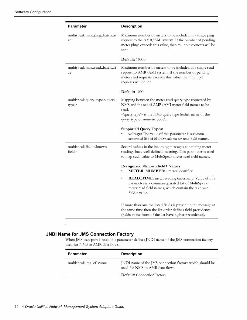
Software Configuration
JNDI Name for JMS Connection FactoryWhen JMS transport is used this parameter defines JNDI name of the JMS connection factory used for NMS to AMR data flows.
multispeak.max_ping_batch_size
Maximum number of meters to be included in a single ping request to the AMR/AMI system. If the number of pending meter pings exceeds this value, then multiple requests will be sent.
Default: 10000
multispeak.max_read_batch_size
Maximum number of meters to be included in a single read request to AMR/AMI system. If the number of pending meter read requests exceeds this value, then multiple requests will be sent.
Default: 1000
multispeak.query_type.<query type>
Mapping between the meter read query type requested by NMS and the set of AMR/AMI meter field names to be read.<query type> is the NMS query type (either name of the query type or numeric code).
Supported Query Types: • voltage: The value of this parameter is a comma-
separated list of MultiSpeak meter read field names.
multispeak.field.<known field>
Several values in the incoming messages containing meter readings have well-defined meaning. This parameter is used to map such value to MultiSpeak meter read field names.
Recognized <known field> Values: • METER_NUMBER: - meter identifier
• READ_TIME: meter reading timestamp. Value of this parameter is a comma-separated list of MultiSpeak meter read field names, which contain the <known field> value.
If more than one the listed fields is present in the message at the same time then the list order defines field precedence (fields at the front of the list have higher precedence).
Parameter Description
Parameter Description
multispeak.jms_cf_name JNDI name of the JMS connection factory which should be used for NMS to AMR data flows.
Default: ConnectionFactory
11-14 Oracle Utilities Network Management System Adapters Guide

Software Configuration
JMS Connection CredentialsThese parameters are used if credentials are required to establish connection to JMS server. They are passed to the createConnection method of JMS connection factory.
AMR_LINKSThe AMR_LINKS database table is used to configure communication links to the AMI/AMR system. It is allowed to configure multiple links. The adapter will use the active link with the lowest value in the PRIORITY column. The adapter will not automatically switch to another link if the current link fails. HTTP/HTTPS and JMS links are supported.
For HTTP links WS_URL column is used to specify URL of the AMI/AMR system web service.
For JMS links, the REQUEST_QUEUE and RESPONSE_QUEUE columns are used to specify JNDI names of JMS queues used to send requests to and receive responses from AMI/AMR system.
The value in the TIMEOUT column controls how long the adapter should wait for response from AMI/AMR system (in seconds). This is only applicable to JMS links. The maximum allowed value is 3600 (1 hour).
The value in the PERSISTENT column defines delivery mode for JMS messages. If set to 'Y' then JMS messages are persistent, otherwise they are not persistent. By default, messages are not persistent. This is only applicable to JMS links.
Configuration in this table, if present, overrides existing configuration parameter 'multispeak.od_oa.url'.
ExampleINSERT INTO amr_links (id, ws_url, priority, active)VALUES (1, 'http://localhost:8088/mockAMR', 1, 'Y');INSERT INTO amr_links (id, ws_url, priority, active)VALUES (2, 'http://localhost:8089/mockAMR', 2, 'N');INSERT INTO amr_links (id, request_queue, response_queue, timeout, persistent, priority, active)VALUES (3, 'queue/AmrRequest', 'queue/AmrResponse', 30, 'N', 3, 'N');
Parameter Description
multispeak.jms_user JMS connection username.
multispeak.jms_password JMS connection password.
MultiSpeak Adapter 11-15
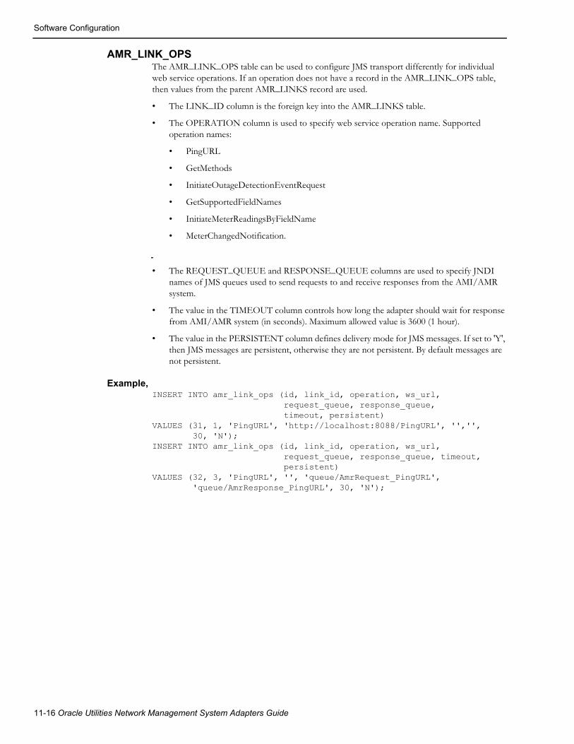
Software Configuration
AMR_LINK_OPSThe AMR_LINK_OPS table can be used to configure JMS transport differently for individual web service operations. If an operation does not have a record in the AMR_LINK_OPS table, then values from the parent AMR_LINKS record are used.
• The LINK_ID column is the foreign key into the AMR_LINKS table.
• The OPERATION column is used to specify web service operation name. Supported operation names:
• PingURL
• GetMethods
• InitiateOutageDetectionEventRequest
• GetSupportedFieldNames
• InitiateMeterReadingsByFieldName
• MeterChangedNotification.
• The REQUEST_QUEUE and RESPONSE_QUEUE columns are used to specify JNDI names of JMS queues used to send requests to and receive responses from the AMI/AMR system.
• The value in the TIMEOUT column controls how long the adapter should wait for response from AMI/AMR system (in seconds). Maximum allowed value is 3600 (1 hour).
• The value in the PERSISTENT column defines delivery mode for JMS messages. If set to 'Y', then JMS messages are persistent, otherwise they are not persistent. By default messages are not persistent.
Example,INSERT INTO amr_link_ops (id, link_id, operation, ws_url, request_queue, response_queue, timeout, persistent)VALUES (31, 1, 'PingURL', 'http://localhost:8088/PingURL', '','', 30, 'N');INSERT INTO amr_link_ops (id, link_id, operation, ws_url, request_queue, response_queue, timeout, persistent)VALUES (32, 3, 'PingURL', '', 'queue/AmrRequest_PingURL', 'queue/AmrResponse_PingURL', 30, 'N');
11-16 Oracle Utilities Network Management System Adapters Guide

Software Configuration
Overriding Configuration ParametersThe MultiSpeak Adapter configuration parameters (in the CES_PARAMETERS database table) can be overridden by setting system properties when starting the WebLogic server where the adapter is deployed.
The format of the Java Virtual Machine command-line argument for setting system property.
-D<component>.<configuration parameter>=<value>
where
• component: MultiSpeak Adapter component the configuration parameter applies to.
Possible values:
• AVLInterface
• AMRInterface
• SCADAInterface
• configuration parameter: configuration parameter name
• value: configuration parameter value
Example
Disable the MultiSpeak adapter's AMR component by setting the AMR component's 'config.enabled' configuration parameter to false.
-DAMRInterface.config.enabled=false
MultiSpeak Adapter 11-17

Software Configuration
Storing Meter Readings in AMR_RESPONSES TableIf the adapter is used to request meter readings from the AMR/AMI system the received values are stored in the AMR_RESPONSES database table. Product configuration provides single column (VOLTAGE) for storing meter readings. If additional values need to be stored then desired number of columns should be added to the AMR_RESPONSES table and project-specific version of the eclipselink-orm.xml configuration file need to be created. The columns should have type VARCHAR2. The below set of directions should be used to define your project version of this file.
1. In your <project>/jconfig directory, create a subdirectory structure as follows:
<project>/jconfig/override/nms-multispeak-ejb.jar/META-INF/
2. Copy the Product version of the eclipselink-orm.xml file used by MultiSpeak adapter.
Note: This file can be found in the product/jconfig/override/nms-multispeak-ejb.jar/META-INF/ directory.
3. Save the file to the META-INF directory that you created in step 1.
4. In the file you should find the following entry (enclosing entity-mapping tag is omitted) for mapping meter read field "Voltage" to the column VOLTAGE in the AMR_RESPONSES table.
<entity class="com.splwg.oms.interfaces.amr.model.MeterStatus"> <attributes> <basic name="Voltage" access="VIRTUAL" attribute-type="String"> <column name="VOLTAGE"/> </basic> </attributes> </entity>
5. Add additional <basic> elements for the columns added to the AMR_RESPONSES table. Attribute 'name' defines the name of the meter read field coming from the AMR/AMI system. Attribute 'access' should have value 'VIRTUAL'. Attribute 'attribute-type' should have value 'String'. Nested element <column> defines the database column name.
6. Execute 'nms-install-config --java' to generate new nms-multispeak.ear binary.
11-18 Oracle Utilities Network Management System Adapters Guide
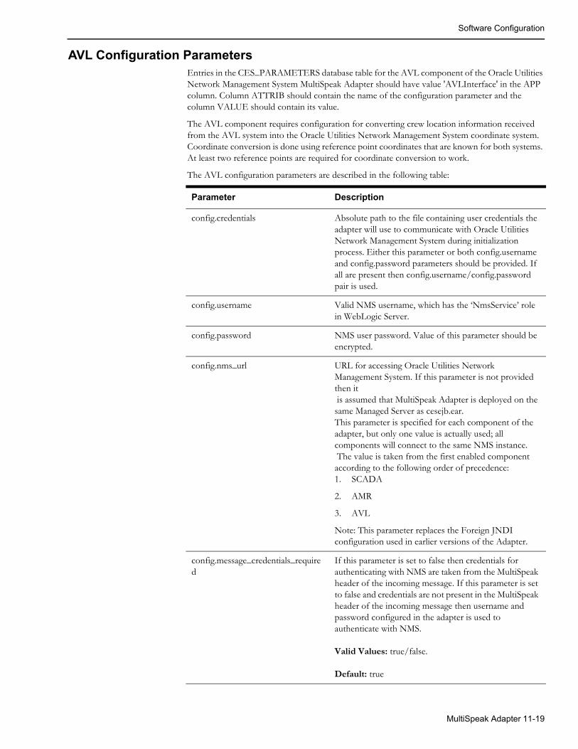
Software Configuration
AVL Configuration ParametersEntries in the CES_PARAMETERS database table for the AVL component of the Oracle Utilities Network Management System MultiSpeak Adapter should have value 'AVLInterface' in the APP column. Column ATTRIB should contain the name of the configuration parameter and the column VALUE should contain its value.
The AVL component requires configuration for converting crew location information received from the AVL system into the Oracle Utilities Network Management System coordinate system. Coordinate conversion is done using reference point coordinates that are known for both systems. At least two reference points are required for coordinate conversion to work.
The AVL configuration parameters are described in the following table:
Parameter Description
config.credentials Absolute path to the file containing user credentials the adapter will use to communicate with Oracle Utilities Network Management System during initialization process. Either this parameter or both config.username and config.password parameters should be provided. If all are present then config.username/config.password pair is used.
config.username Valid NMS username, which has the ‘NmsService’ role in WebLogic Server.
config.password NMS user password. Value of this parameter should be encrypted.
config.nms_url URL for accessing Oracle Utilities Network Management System. If this parameter is not provided then it is assumed that MultiSpeak Adapter is deployed on the same Managed Server as cesejb.ear.This parameter is specified for each component of the adapter, but only one value is actually used; all components will connect to the same NMS instance. The value is taken from the first enabled component according to the following order of precedence:1. SCADA
2. AMR
3. AVL
Note: This parameter replaces the Foreign JNDI configuration used in earlier versions of the Adapter.
config.message_credentials_required
If this parameter is set to false then credentials for authenticating with NMS are taken from the MultiSpeak header of the incoming message. If this parameter is set to false and credentials are not present in the MultiSpeak header of the incoming message then username and password configured in the adapter is used to authenticate with NMS.
Valid Values: true/false.
Default: true
MultiSpeak Adapter 11-19

Software Configuration
Credentials FilesCredentials files may be used to configure usernames and passwords to be used by the parts of the adapter that communicate with the Oracle Utilities Network Management System.
Credentials files should only be readably by the operating system account under which application server is running.
The format of a credentials file is described in the following table:
The following illustration shows a sample credentials file.
#nms.username=amrnms.password=amr-user-password
avl.num_reference_points Number of configured reference points
avl.reference_point<N>.x X coordinate of the reference point N in the Oracle Utilities Network Management System coordinate system
avl.reference_point<N>.y Y coordinate of the reference point N in the Oracle Utilities Network Management System coordinate system
avl.reference_point<N>.longitude Geographic longitude of the reference point N
avl.reference_point<N>.latitude Geographic latitude of the reference point N
avl.xy_scale Number of decimal points to use when rounding X/Y coordinates
avl.lat_long_scale Number of decimal points for rounding longitude/latitude coordinates
config.enabled Enables AVL processingDefault: false
Parameter Description
Property Description
nms.username Valid NMS username, which has the NmsService role in WebLogic Server.
nms.password NMS user password
11-20 Oracle Utilities Network Management System Adapters Guide

Software Configuration
Oracle Utilities Network Management System Configuration RulesBelow is the list of configuration rules in the Oracle Utilities Network Management System, which control AMR-related functionality. These rules are not directly used by the Oracle Utilities Network Management System MultiSpeak Adapter.
amrInterfacesEnabledThis rule enables AMR processing in JMService. Its value indicates the AMR processing types that are available. AMR processing is disabled if this rule is set to 0 (default value).
Available types of AMR processing:
• 1 - Outage detection
• 2 - PSO verification
• 4 - PDO verification
• 8 - Restoration verification
• 16 - Manual AMR processing
• 32 - Unsolicited power-up processing
The rule value is a bitmask, which allows any combination of AMR processing types to be enabled. For example, if you want to enable outage detection (1) and restoration verification (8) processing, you would set the rule to 9.
meterOffThresholdMaximum probability of meter having power when meter is still assumed to be "off". The default value is 0.
meterOffTroubleCodeTrouble code to be used when a call should be created because of information received from AMR system.
meterOnThresholdMinimum probability of meter having power when meter is still assumed to be "on". The default value is 100.
meterQueryThresholdThis parameter is used to determine if a meter can be queried when an active request exists. When a new request is made, existing requests will be evaluated to see if any contain meter(s) from the new request. If a match is found, and the difference between the time the request was received and current time is less than value of this rule in seconds, that meter will be rejected from the new request. If set to -1 (default value), this rule will not be enforced.
meterPingPercentageThis parameter governs the percentage of meters to ping for an AMR action. When set to 100, it will ping all AMR meters downstream from the outage device. When set to -1, it will ping one AMR meter on each SND. When set to any other number between 1 and 99, JMService will attempt to ping the specified percentage of meters for each transformer affected by the outage (the resulting number of meters is rounded up so that at least one meter per transformer is pinged). It is possible to configure this rule differently for different device classes. The default value of this rule is 100.
MultiSpeak Adapter 11-21

Software Configuration
useMeterTimeForDetectionThis configuration rule determines if meter read time reported by AMR system should be used as call time for incidents created by outage detection functionality.
Valid values:
• no - Meter read time will not be used, instead current system time will be used (this is the default behavior)
• yes - Meter read time will be used
If the rule_value_2 is greater than 0, and the difference between the current time and the meter read time is greater than the number of seconds specified by rule_value_2, then the meter read is too old for outage detection. The default value is 3600 seconds (1 hour).
useMeterTimeForRestorationThis configuration rule determines if meter read time reported by AMR system should be used to adjust outage restoration time as part of outage restoration verification functionality. Outage restoration time is only updated if restoration time calculated from AMR data is earlier then the current restoration time.
Valid values:
• no - outage restoration time will not be modified
• latest - outage restoration time will be updated with the latest meter read time amongst the meters which reported power on for the restored outage (this is the default behavior)
• earliest - outage restoration time will be updated with the earliest meter read time amongst the meters which reported power on for the restored outage
• percentile - outage restoration time will be updated with the earliest meter read time which covers the desired percentile of meters which have reported power on. Percentile value is specified using rule_value_2 field. It should be in the range from 1 to 99 (inclusive).
Meter read times preceding outage start time or past current time are ignored.
Example of ‘percentile’ setting.
rule_value_1 = 'percentile' rule_value_2 = 50
This configuration corresponding to using median value from the all meter read times for meters, which reported power on. Given following four meter read times
00:00:1000:00:1100:00:2000:00:30the median value would be 00:00:11 (second value out of four).
meterRequestSendDelayThis configuration rule is used to control how long the outage prediction engine should wait before sending a meter ping request to the MultiSpeak adapter. This rule is only applicable for PSO Verification, PDO Verification, and Restoration Verification requests.
meterRequestTTLThis configuration rule is used to control the “time-to-live” (TTL) for meter ping requests. This is the period of time NMS will wait for a responses from AMR system. Automated meter ping requests (PSO Verification, PDO Verification, and Restoration Verification) are considered completed when TTL expires. Manual meter ping requests, which were not explicitly completed or cancelled by the user, are automatically cancelled when TTL expires.
11-22 Oracle Utilities Network Management System Adapters Guide

Adapter Interface Communication Overview
TTL is configurable per request type. It can either be a fixed value (for example, the PSO Verification request can remain active for 15 minutes) or it can be calculated based on the number of meters in the request combined with minimum and maximum values. If TTL is set to 0, then automated meter ping requests remain active until the first response is received. Manual meter ping requests in this case remain active until explicitly completed or cancelled by the user.
meterPingSuppressThis configuration rule can be used to suppress sending meter ping requests to the AMR system based on the request type.
writePowerOffsToDBThis configuration rule determines if JMService will create a new incident when a power-off message is received from the AMR system.
If this rule is set to "no", then incidents for power-off messages will be created by JMService. This is the default behavior.
If this rule is set to "yes", then, instead of creating an incident, JMService will insert a record into the AMR_POWER_OFFS database table. This record will contain the meter id and power-off timestamp. An external process is expected to read the table and process new entries.
For example, such a process can obtain customer information associated with the meter id and insert a record into the TROUBLE_CALLS table so that the NMS IVR Adapter will process it and create a new incident. This allows more flexibility to the process of creating incidents from AMR-reported power-off messages.
Adapter Interface Communication OverviewThe Oracle Utilities Network Management System MultiSpeak Adapter provides a reliable and configurable way of connecting MultiSpeak-compliant AMR, AVL, and SCADA systems to the Oracle Utilities Network Management System. The interface connects to the AMR systems by use of MultiSpeak-compliant SOAP/XML calls over the HTTPS protocol. JMS queues can also be used as the transport mechanism. The interface connects to the Oracle Utilities Network Management System through direct database access using JDBC and by use of a CORBA connection through the Oracle Utilities Network Management System Web Gateway.
MultiSpeak Adapter 11-23

Adapter Interface Communication Overview
11-24 Oracle Utilities Network Management System Adapters Guide

Adapter Design
Adapter Design
Supported Data FlowsOracle Utilities Network Management System MultiSpeak Adapter supports following data flows described in the MultiSpeak Web Services Version 4.1 specification.
Oracle Utilities Network Management System to an AMR system:
• InitiateOutageDetectionEventRequest
Oracle Utilities Network Management System requests meter status information from the AMR system.
• InitiateMeterReadingsByFieldName
Oracle Utilities Network Management System requests specified meter readings for the listed set of meters from the AMR system.
• MeterChangedNotification
Oracle Utilities Network Management System requests that the AMR/AMI system enables or disables messages from specific meters. For example, this flow can be used to temporarily disable messages from a meter which is giving faulty readings. NMS sends meterStatus value "Inactive" to disable a meter and "Active" value to enable it.
An AMR system to Oracle Utilities Network Management System:
• ODEventNotification
AMR system reports meter status information to the Oracle Utilities Network Management System.
• FormattedBlockNotification
AMR system reports meter readings to Oracle Utilities Network Management system. This message is sent in response to the InitiateMeterReadingsByFieldName request.
• MeterChangedNotification
AMR/AMI system reports to Oracle Utilities Network Management System that one or more meters are enabled or disabled. NMS expects an "Inactive" meterStatus value when the meter is disabled and "Active" value when it is enabled.
An AVL system to Oracle Utilities Network Management System:
• AVLChangedNotification
AVL system reports crew location information to the Oracle Utilities Network Management System.
Incoming requests (ODEventNotification, FormattedBlockNotification, AVLChangedNotification, and MeterChangedNotification) are authenticated against the list of valid Oracle Utilities Network Management System users.
MultiSpeak Adapter 11-25
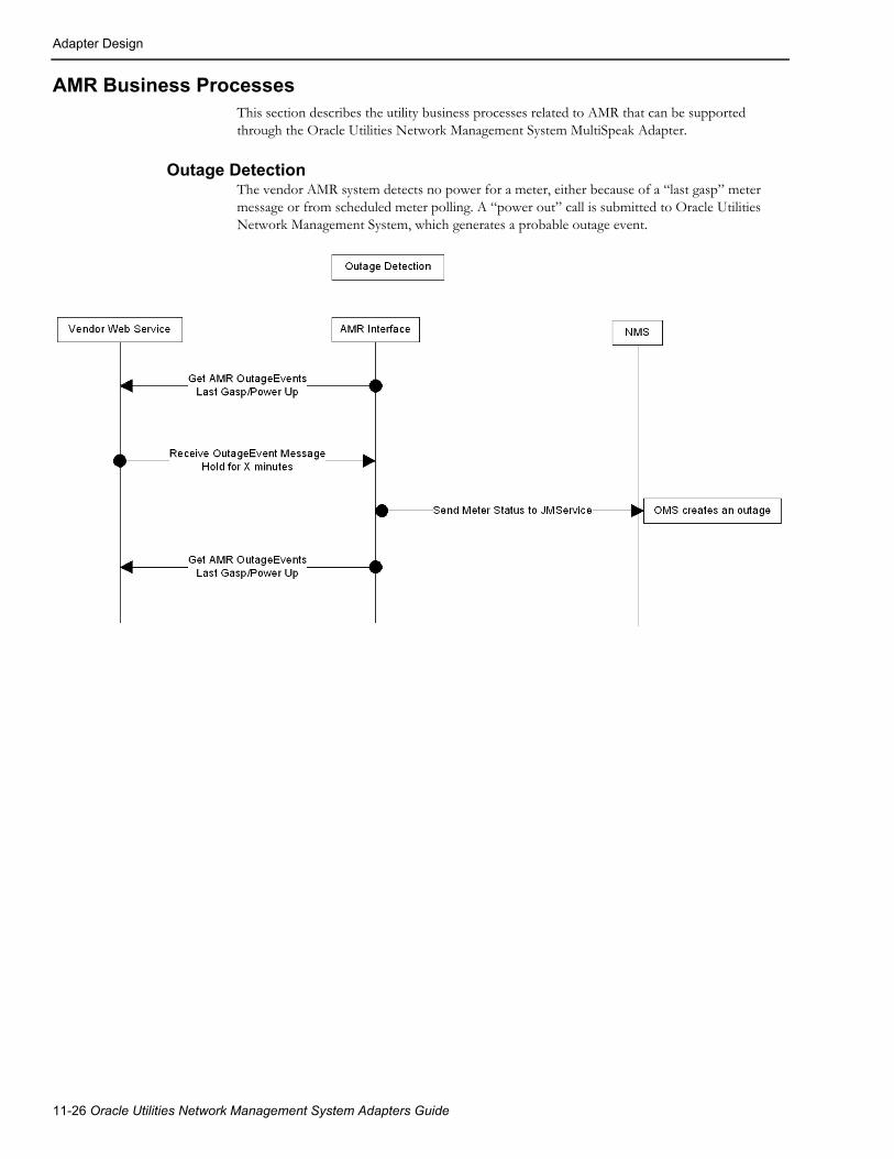
Adapter Design
AMR Business ProcessesThis section describes the utility business processes related to AMR that can be supported through the Oracle Utilities Network Management System MultiSpeak Adapter.
Outage Detection The vendor AMR system detects no power for a meter, either because of a “last gasp” meter message or from scheduled meter polling. A “power out” call is submitted to Oracle Utilities Network Management System, which generates a probable outage event.
11-26 Oracle Utilities Network Management System Adapters Guide
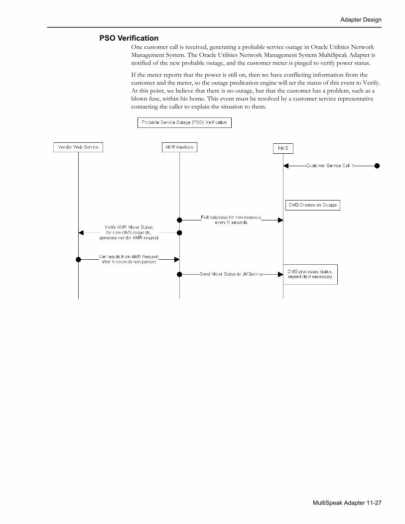
Adapter Design
PSO VerificationOne customer call is received, generating a probable service outage in Oracle Utilities Network Management System. The Oracle Utilities Network Management System MultiSpeak Adapter is notified of the new probable outage, and the customer meter is pinged to verify power status.
If the meter reports that the power is still on, then we have conflicting information from the customer and the meter, so the outage predication engine will set the status of this event to Verify. At this point, we believe that there is no outage, but that the customer has a problem, such as a blown fuse, within his home. This event must be resolved by a customer service representative contacting the caller to explain the situation to them.
MultiSpeak Adapter 11-27
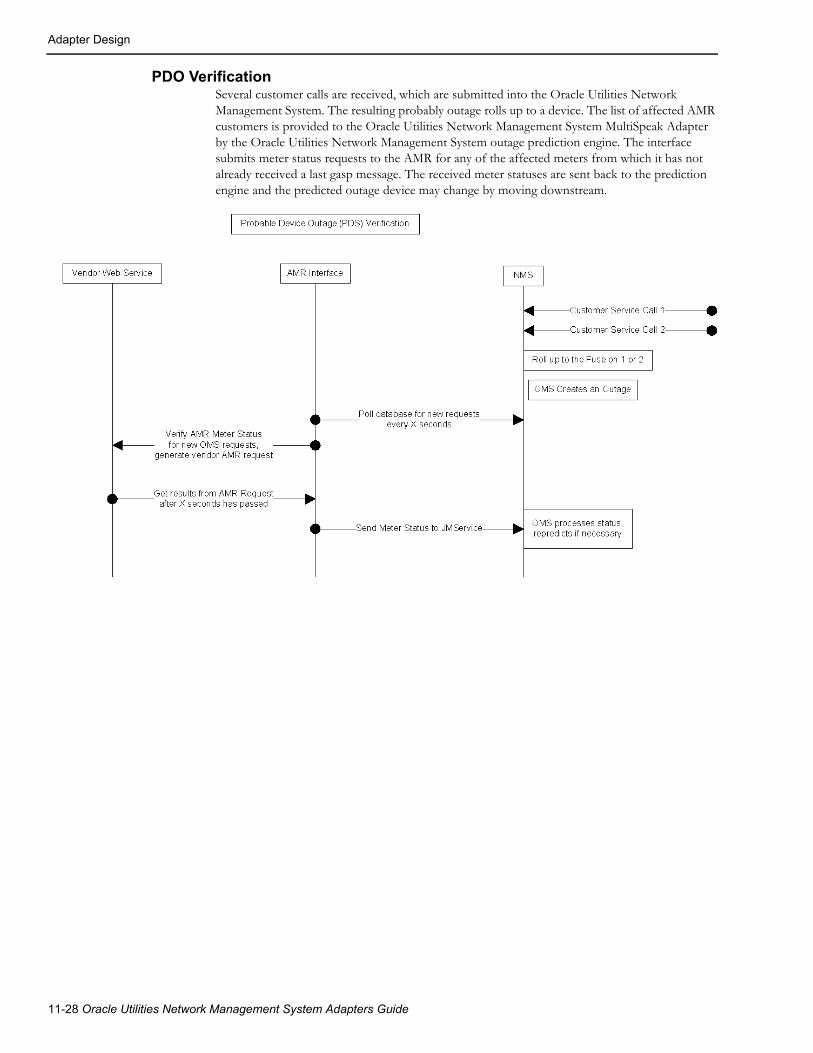
Adapter Design
PDO VerificationSeveral customer calls are received, which are submitted into the Oracle Utilities Network Management System. The resulting probably outage rolls up to a device. The list of affected AMR customers is provided to the Oracle Utilities Network Management System MultiSpeak Adapter by the Oracle Utilities Network Management System outage prediction engine. The interface submits meter status requests to the AMR for any of the affected meters from which it has not already received a last gasp message. The received meter statuses are sent back to the prediction engine and the predicted outage device may change by moving downstream.
11-28 Oracle Utilities Network Management System Adapters Guide
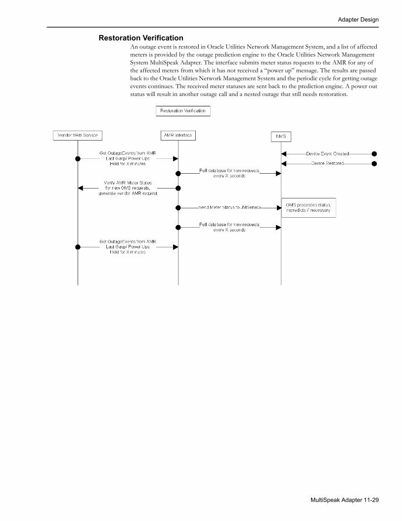
Adapter Design
Restoration VerificationAn outage event is restored in Oracle Utilities Network Management System, and a list of affected meters is provided by the outage prediction engine to the Oracle Utilities Network Management System MultiSpeak Adapter. The interface submits meter status requests to the AMR for any of the affected meters from which it has not received a “power up” message. The results are passed back to the Oracle Utilities Network Management System and the periodic cycle for getting outage events continues. The received meter statuses are sent back to the prediction engine. A power out status will result in another outage call and a nested outage that still needs restoration.
MultiSpeak Adapter 11-29
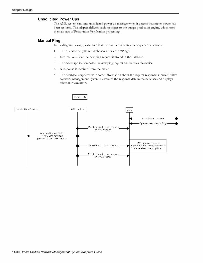
Adapter Design
Unsolicited Power UpsThe AMR system can send unsolicited power up message when it detects that meter power has been restored. The adapter delivers such messages to the outage prediction engine, which uses them as part of Restoration Verification processing.
Manual PingIn the diagram below, please note that the number indicates the sequence of actions:
1. The operator or system has chosen a device to “Ping”.
2. Information about the new ping request is stored in the database.
3. The AMR application notes the new ping request and verifies the device.
4. A response is received from the meter.
5. The database is updated with some information about the request response. Oracle Utilities Network Management System is aware of the response data in the database and displays relevant information.
11-30 Oracle Utilities Network Management System Adapters Guide

Adapter Design
Urgent PingThe adapter supports the ability to immediately ping a single meter. Such ping requests are initiated by sending PING high-level message containing single meter id to the adapter. Requests received via high-level message are processed right away without being subject to batching. They do not persist in database. Cache is not used to satisfy such requests so the AMR system is always contacted.
Business Scenario:1. The operator or system has chosen a device to “Ping.”
2. PING high-level message containing meter id is sent to the adapter.
3. The adapter sends ping request to the AMR system.
4. A response is received from the AMR system.
5. The adapter sends PING_RESPONSE high-level message containing received meter status back to the client.
Reading Meter ValuesIn addition to requesting meter status information (pinging meters) the adapter can request meter readings of such values as voltage, current, etc. (depending of meter capabilities) from the AMR/AMI system.
Bellwether meters are a special case of requesting meter readings. For meters configured as bellwether the adapter would periodically issue meter read request to the AMR/AMI system and then publish received values as SCADA measurements.
Using Meter Voltages to Determine Power StatusSome utilities have multi-phase meters, especially in downtown mesh networks. Conventional meter power status pings only indicate that the meter has power, but not whether some phases do not have power. The adapter can use meter voltage information to form a more accurate picture of meters where one or two phases/legs may not have power. When using voltage to determine meter power status the adapter will consider meter as de-energized if any of the reported meter voltage values are below the low voltage threshold configured for the meter. The meter is considered energized if all the reported meter voltage values are at or above the low voltage threshold.
The following configuration tasks need to be performed to enable this functionality in the adapter:
1. Define low voltage threshold.
The MultiSpeak adapter uses the value from the VOLTAGE_THRESHOLD column in the AMR_CU_METERS table as low voltage threshold for a meter. This column needs to be populated in order for the adapter to use voltage read to determine meter power status.
The voltage threshold value needs to be put into the VOLTAGE_THRESHOLD column in the CU_METERS_CIS table. When the product_update_customers.ces script is executed, this value will be propagated to the CU_METERS and AMR_CU_METERS tables.
2. Configure the adapter to use voltage read to determine meter power status.
The config.use_voltage_ping parameter needs to be set the value 'multiphase' or 'always'.
Example,
INSERT INTO ces_parameters (app, attrib, value)VALUES ('AMRInterface', 'config.use_voltage_ping', 'multiphase');
MultiSpeak Adapter 11-31

Adapter Design
3. Provide phasing information for meters.
If the config.use_voltage_ping configuration parameter is set to ‘multiphase,’ then the adapter needs a way to distinguish multiphase meters. This is done by checking the value in the AMR_CU_METERS.METER_PHASES column against the list of values specified in the configuration parameter. The AMR_CU_METERS.METER_PHASES column is populated from the CU_METERS_CIS.METER_PHASES column when product_update_customers.ces script is executed.
For example:
INSERT INTO ces_parameters (app, attrib, value)VALUES ('AMRInterface', 'config.multiphase_meter', '3,5,6,7');
4. Define query types for requesting meter voltage information from the AMI system.
The config.voltage_query_type and config.phase_voltage_query_type configuration parameters need to specify query type names used to requests voltages from AMI system. config.voltage_query_type is used for single phase meter, and config.phase_voltage_query_type is used for multiphase meters. For each query type, a multispeak.query_type.<query type name> configuration parameter needs to specify the list of fields to be read from the AMI system (this configuration depends on AMI vendor).
For example:
INSERT INTO ces_parameters (app, attrib, value)VALUES ('AMRInterface', 'config.voltage_query_type', 'voltage');
INSERT INTO ces_parameters (app, attrib, value)VALUES ('AMRInterface', 'config.phase_voltage_query_type',
'phase_voltage');
INSERT INTO ces_parameters (app, attrib, value)VALUES ('AMRInterface', 'multispeak.query_type.voltage',
'Voltage');
INSERT INTO ces_parameters (app, attrib, value)VALUES ('AMRInterface', 'multispeak.query_type.phase_voltage', 'VoltageA,VoltageB,VoltageC');
11-32 Oracle Utilities Network Management System Adapters Guide
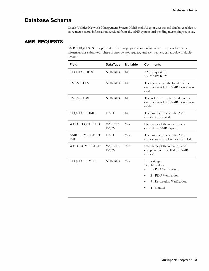
Database Schema
Database SchemaOracle Utilities Network Management System MultiSpeak Adapter uses several databases tables to store meter status information received from the AMR system and pending meter ping requests.
AMR_REQUESTSAMR_REQUESTS is populated by the outage prediction engine when a request for meter information is submitted. There is one row per request, and each request can involve multiple meters.
Field DataType Nullable Comments
REQUEST_IDX NUMBER No AMR request id.PRIMARY KEY
EVENT_CLS NUMBER No The class part of the handle of the event for which the AMR request was made.
EVENT_IDX NUMBER No The index part of the handle of the event for which the AMR request was made.
REQUEST_TIME DATE No The timestamp when the AMR request was created.
WHO_REQUESTED VARCHAR2(32)
Yes User name of the operator who created the AMR request.
AMR_COMPLETE_TIME
DATE Yes The timestamp when the AMR request was completed or cancelled.
WHO_COMPLETED VARCHAR2(32)
Yes User name of the operator who completed or cancelled the AMR request.
REQUEST_TYPE NUMBER Yes Request type.Possible values:• 1 - PSO Verification
• 2 - PDO Verification
• 3 - Restoration Verification
• 4 - Manual
MultiSpeak Adapter 11-33

Database Schema
AMR_RESPONSESThe AMR_RESPONSES table is used to transfer meter status information between the outage prediction engine and the MultiSpeak adapter. The outage prediction engine inserts rows into this table when a request for meter information is submitted. Every request in AMR_RESPONSES is represented by one row for each meter requested. The MultiSpeak adapter updates this table as requested meter status information becomes available.
QUERY_TYPE NUMBER Yes Query type.Possible values:• 0 - simple meter status query
• 1 - complex meter information query
• 100 - voltage query
• 101 - phase voltage query
Note: Query types with values below 100 are meter status (ping) queries. Query types with values 100 and above are meter read queries.
STATUS NUMBER Yes Status of the AMR request.Possible values:1- active2 - explicitly completed3 -cancelled
DEVICE_CLS NUMBER Yes The class part of the handle of the device for which the AMR request was made.
DEVICE_IDX NUMBER Yes The index part of the handle of the device for which the AMR request was made.
NCG NUMBER Yes NCG of the device for which the AMR request was made.
TTL NUMBER(9)
Yes The Time-To-Live of the request in seconds.
Field DataType Nullable Comments
Field DataType Nullable Comments
ID Number No Unique record identifier. PRIMARY KEY
REQUEST_IDX NUMBER Yes AMR request id.
REQUEST_TIME DATE Yes Request timestamp.
METER_NO VARCHAR2(256) Yes Meter number as known to the AMR system
METER_ID NUMBER No NMS meter identifier.
11-34 Oracle Utilities Network Management System Adapters Guide

Database Schema
REQ_STATUS VARCHAR2(1) Yes Request status.Possible values:• N - new request (not yet sent
to AMR)
• P - pending request (waiting for AMR response)
• S - suppressed request
• R - AMR response received
• C - completed request
STATUS VARCHAR2(256) Yes Meter status received from AMR.Possible values:• ON - meter has power
• OFF - meter does not have power
AMR_ERROR VARCHAR2(256) Yes Error message received from the AMR system.
RECEIVED_TIME DATE Yes Timestamp when the response was received from the AMR system.
RESULT_TIME DATE Yes Timestamp returned by the AMR system for the meter status.
PROBABILITY NUMBER Yes The probability of the meter having power (0 - no power; 100 - meter has power.)
ATTEMPT_COUNT NUMBER(3) Yes Count of the attempts made to send a request to the AMR system.
VOLTAGE VARCHAR2(16) Yes Meter voltage reading.
VOLTAGE_A VARCHAR2(16) Yes Meter phase A voltage reading.
VOLTAGE_B VARCHAR2(16) Yes Meter phase B voltage reading.
VOLTAGE_C VARCHAR2(16) Yes Meter phase C voltage reading.
Field DataType Nullable Comments
MultiSpeak Adapter 11-35
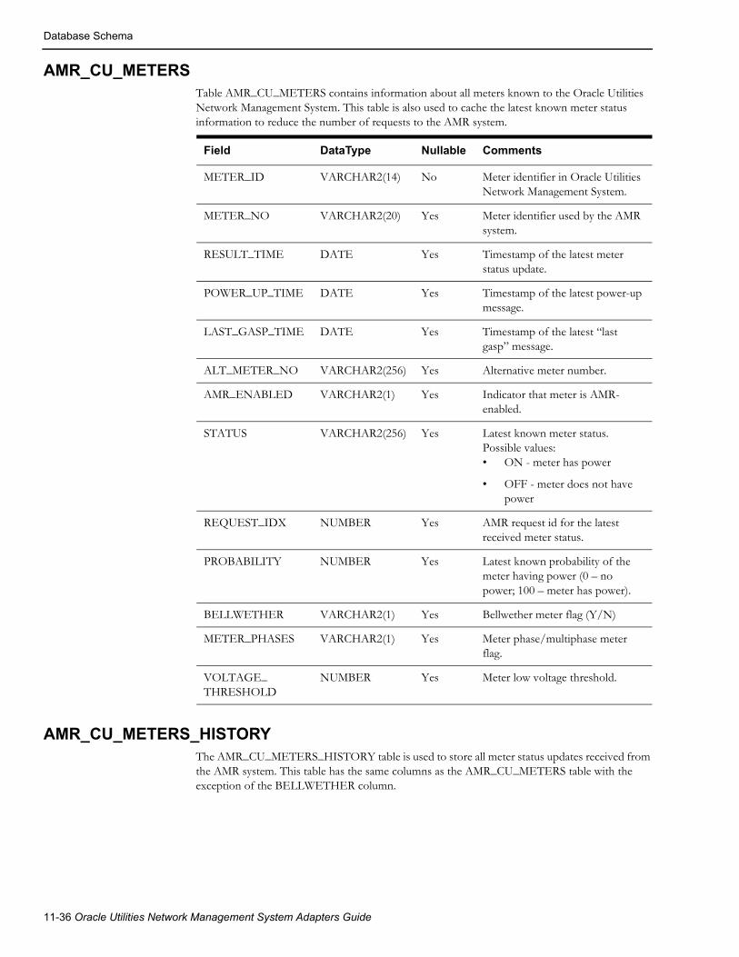
Database Schema
AMR_CU_METERSTable AMR_CU_METERS contains information about all meters known to the Oracle Utilities Network Management System. This table is also used to cache the latest known meter status information to reduce the number of requests to the AMR system.
AMR_CU_METERS_HISTORYThe AMR_CU_METERS_HISTORY table is used to store all meter status updates received from the AMR system. This table has the same columns as the AMR_CU_METERS table with the exception of the BELLWETHER column.
Field DataType Nullable Comments
METER_ID VARCHAR2(14) No Meter identifier in Oracle Utilities Network Management System.
METER_NO VARCHAR2(20) Yes Meter identifier used by the AMR system.
RESULT_TIME DATE Yes Timestamp of the latest meter status update.
POWER_UP_TIME DATE Yes Timestamp of the latest power-up message.
LAST_GASP_TIME DATE Yes Timestamp of the latest “last gasp” message.
ALT_METER_NO VARCHAR2(256) Yes Alternative meter number.
AMR_ENABLED VARCHAR2(1) Yes Indicator that meter is AMR-enabled.
STATUS VARCHAR2(256) Yes Latest known meter status.Possible values:• ON - meter has power
• OFF - meter does not have power
REQUEST_IDX NUMBER Yes AMR request id for the latest received meter status.
PROBABILITY NUMBER Yes Latest known probability of the meter having power (0 – no power; 100 – meter has power).
BELLWETHER VARCHAR2(1) Yes Bellwether meter flag (Y/N)
METER_PHASES VARCHAR2(1) Yes Meter phase/multiphase meter flag.
VOLTAGE_THRESHOLD
NUMBER Yes Meter low voltage threshold.
11-36 Oracle Utilities Network Management System Adapters Guide
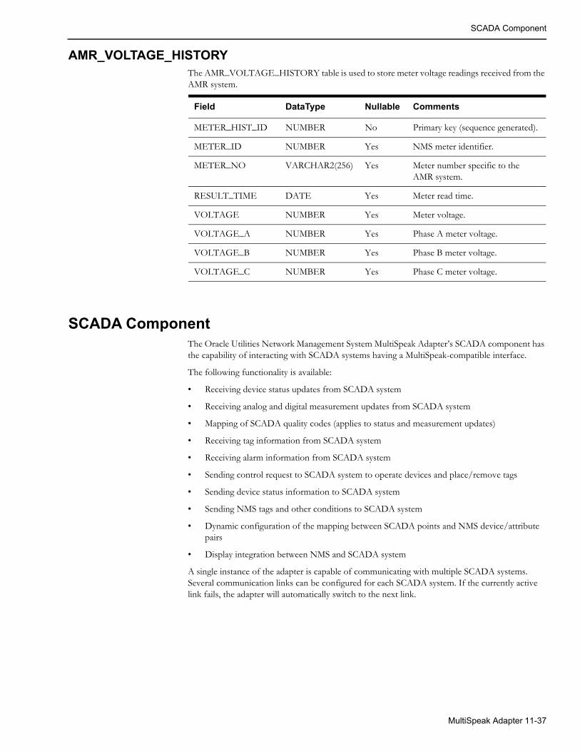
SCADA Component
AMR_VOLTAGE_HISTORYThe AMR_VOLTAGE_HISTORY table is used to store meter voltage readings received from the AMR system.
SCADA ComponentThe Oracle Utilities Network Management System MultiSpeak Adapter’s SCADA component has the capability of interacting with SCADA systems having a MultiSpeak-compatible interface.
The following functionality is available:
• Receiving device status updates from SCADA system
• Receiving analog and digital measurement updates from SCADA system
• Mapping of SCADA quality codes (applies to status and measurement updates)
• Receiving tag information from SCADA system
• Receiving alarm information from SCADA system
• Sending control request to SCADA system to operate devices and place/remove tags
• Sending device status information to SCADA system
• Sending NMS tags and other conditions to SCADA system
• Dynamic configuration of the mapping between SCADA points and NMS device/attribute pairs
• Display integration between NMS and SCADA system
A single instance of the adapter is capable of communicating with multiple SCADA systems. Several communication links can be configured for each SCADA system. If the currently active link fails, the adapter will automatically switch to the next link.
Field DataType Nullable Comments
METER_HIST_ID NUMBER No Primary key (sequence generated).
METER_ID NUMBER Yes NMS meter identifier.
METER_NO VARCHAR2(256) Yes Meter number specific to the AMR system.
RESULT_TIME DATE Yes Meter read time.
VOLTAGE NUMBER Yes Meter voltage.
VOLTAGE_A NUMBER Yes Phase A meter voltage.
VOLTAGE_B NUMBER Yes Phase B meter voltage.
VOLTAGE_C NUMBER Yes Phase C meter voltage.
MultiSpeak Adapter 11-37
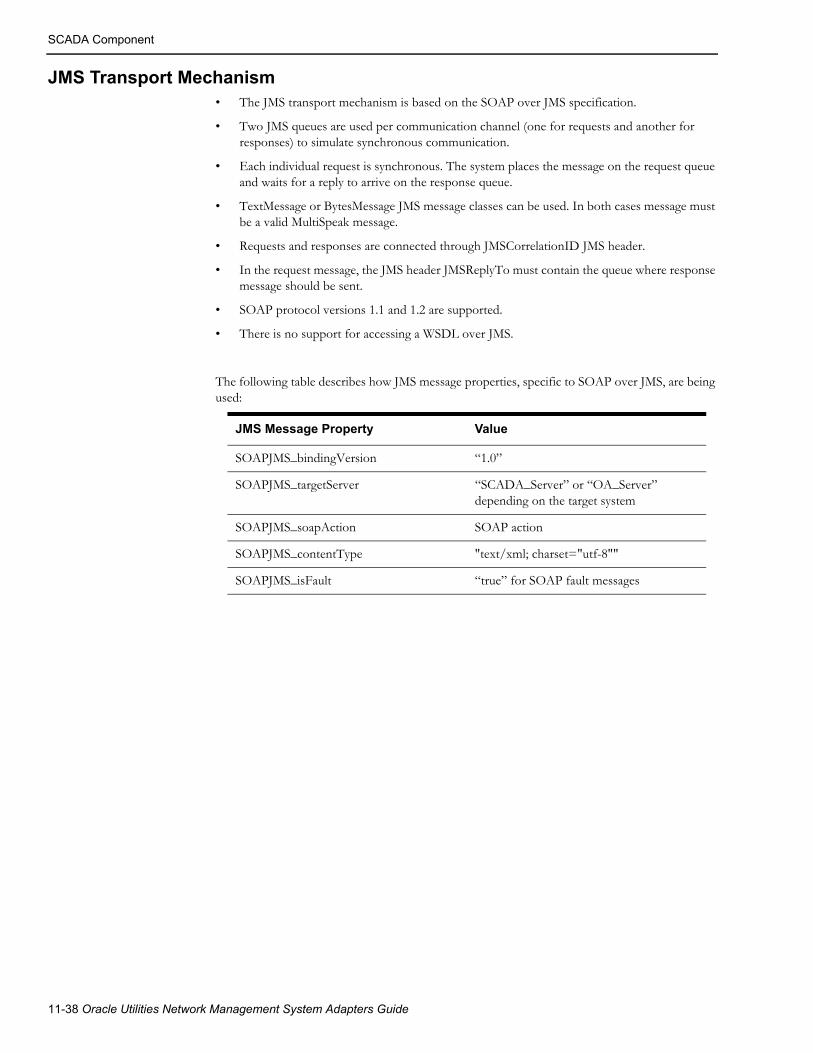
SCADA Component
JMS Transport Mechanism• The JMS transport mechanism is based on the SOAP over JMS specification.
• Two JMS queues are used per communication channel (one for requests and another for responses) to simulate synchronous communication.
• Each individual request is synchronous. The system places the message on the request queue and waits for a reply to arrive on the response queue.
• TextMessage or BytesMessage JMS message classes can be used. In both cases message must be a valid MultiSpeak message.
• Requests and responses are connected through JMSCorrelationID JMS header.
• In the request message, the JMS header JMSReplyTo must contain the queue where response message should be sent.
• SOAP protocol versions 1.1 and 1.2 are supported.
• There is no support for accessing a WSDL over JMS.
The following table describes how JMS message properties, specific to SOAP over JMS, are being used:
JMS Message Property Value
SOAPJMS_bindingVersion “1.0”
SOAPJMS_targetServer “SCADA_Server” or “OA_Server” depending on the target system
SOAPJMS_soapAction SOAP action
SOAPJMS_contentType "text/xml; charset="utf-8""
SOAPJMS_isFault “true” for SOAP fault messages
11-38 Oracle Utilities Network Management System Adapters Guide

SCADA Component
Configuring JMS Support
Incoming Data FlowsSupport for accepting incoming requests over JMS in NMS MultiSpeak adapter is controlled by changing value of the config.multispeak_jms property in $NMS_CONFIG/jconfig/build.properties file.
Possible values:
• none: JMS support is disabled
• single: single JMS queue for all incoming data flows
• multiple: separate JMS queue for each incoming data flow
By default JMS support is disabled.
After modifying the $NMS_CONFIG/jconfig/build.properties file, regenerate the nms-multispeak.ear with the new configuration by executing:
nms-install-config -–java
JNDI names of JMS connection factory and queue(s) used for incoming data flows are fixed.
Connection Factorynms-amr/ConnectionFactory
QueuesSingle Queue Mode -
In single queue mode, all incoming requests are sent to the same JMS queue: nms-amr/queue/OA.
MultiSpeak Adapter 11-39

]Supported Data Flows
]Supported Data Flows
NMS to SCADA
Heartbeat
PingURLThe adapter periodically sends PingURL message to the each configured SCADA system. Failure to send the message or error response from SCADA system (reply contains errorObject element) triggers switch to alternate link (if available). Upon restoration of communication with the SCADA system (PingURL has been sent successfully) synchronization sequence is executed.
PingURL request example
<S:Envelope xmlns:S="http://schemas.xmlsoap.org/soap/envelope/"> <S:Header> <ns4:MultiSpeakMsgHeader xmlns:ns4="http://www.multispeak.org/ Version_4.1_Release" xmlns:ns3="http://www.w3.org/1999/xlink" xmlns:ns2="gml" xmlns="cpsm" /> </S:Header> <S:Body> <ns4:PingURL xmlns:ns4="http://www.multispeak.org/Version_4.1_Release" xmlns:ns3="http://www.w3.org/1999/xlink" xmlns:ns2="gml" xmlns="cpsm" /> </S:Body></S:Envelope>
Synchronization/Integrity CheckThe purpose of the synchronization sequence is to bring the state of devices in the NMS model up-to-date with the SCADA system. NMS supports two synchronization methods for device statuses, digital and analog measurements. At the beginning of the synchronization sequence, NMS will make GetMethods call to determine the list of operations supported by the SCADA system. Synchronization method selection is based on configured preferred method and available SCADA operations.
The synchronization sequence is executed automatically after the connection to a SCADA system is established. It also can be triggered manually using following command
Action -java multispeak.SCADA resync
11-40 Oracle Utilities Network Management System Adapters Guide

]Supported Data Flows
GetMethodsGetMethods retrieves lists of operations the SCADA system implements. It is used to determine available modes of syn-chronization. It is also used to determine if control requests can be send to SCADA.
GetMethods Request and Response Example
<S:Envelope xmlns:S="http://schemas.xmlsoap.org/soap/envelope/"> <S:Header> <ns4:MultiSpeakMsgHeader xmlns:ns4="http://www.multispeak.org/ Version_4.1_Release" xmlns:ns3="http://www.w3.org/1999/xlink" xmlns:ns2="gml" xmlns="cpsm" /> </S:Header> <S:Body> <ns4:GetMethods xmlns:ns4="http://www.multispeak.org/Version_4.1_Release" xmlns:ns3="http://www.w3.org/1999/xlink" xmlns:ns2="gml" xmlns="cpsm" /> </S:Body></S:Envelope>
<soapenv:Envelope xmlns:soapenv="http://schemas.xmlsoap.org/soap/envelope/" xmlns:ver="http://www.multispeak.org/Version_4.1_Release"> <soapenv:Header> <ver:MultiSpeakMsgHeader/> </soapenv:Header> <soapenv:Body> <ver:GetMethodsResponse> <ver:GetMethodsResult> <ver:string>PingURL</ver:string> <ver:string>GetMethods</ver:string> <ver:string>InitiateStatusReadByPointID</ver:string> <ver:string>InitiateAnalogReadByPointID</ver:string> <ver:string>InitiateControl</ver:string> <ver:string>GetAllSCADAStatus</ver:string> <ver:string>GetAllSCADAAnalogs</ver:string> <ver:string>GetAllSCADATags</ver:string> </ver:GetMethodsResult> </ver:GetMethodsResponse> </soapenv:Body></soapenv:Envelope>
GetAllSCADAStatus, GetAllSCADAAnalogsThe first synchronization method involves NMS invoking GetAllSCADAStatus and GetAllSCADAAnalogs operations to request the latest device statuses, digital and analog measurements from the SCADA. SCADA provides the requested information synchronously in the response message.
The MultiSpeak specification allows data to be returned in chunks by the SCADA system. In this case, NMS would have to make multiple GetAllSCADAXXX calls. The element lastReceived is included so that large sets of data can be returned in manageable blocks. lastReceived will carry an empty string the first time in a session that this method is invoked. When multiple calls to this method are required to obtain all of the data, the lastReceived should carry the objectID of the last data instance received in subsequent calls. If the ObjectsRemaining field is present in the MultiSpeak reply message’s message header, it will be used to determine when all of the data has been received. If the ObjectsRemaining field is not present, the empty result set will signal the end of the data.
MultiSpeak Adapter 11-41

]Supported Data Flows
GetAllSCADAStatus Request and Response Example
<S:Envelope xmlns:S="http://schemas.xmlsoap.org/soap/envelope/"> <S:Header> <ns4:MultiSpeakMsgHeader xmlns:ns4="http://www.multispeak.org/ Version_4.1_Release" xmlns:ns3="cpsm" xmlns:ns2="http://www.w3.org/1999/xlink" xmlns:ns1="gml" Pwd="test" UserID="nms" /> </S:Header> <S:Body> <ns4:GetAllSCADAStatus xmlns:ns4="http://www.multispeak.org/ Version_4.1_Release" xmlns:ns3="cpsm" xmlns:ns2="http://www.w3.org/1999/xlink" xmlns:ns1="gml"> <ns4:lastReceived></ns4:lastReceived> </ns4:GetAllSCADAStatus> </S:Body></S:Envelope>
<soapenv:Envelope xmlns:soapenv="http://schemas.xmlsoap.org/soap/envelope/" xmlns:ver="http://www.multispeak.org/Version_4.1_Release" xmlns:cpsm="cpsm"> <soapenv:Header> <ver:MultiSpeakMsgHeader UserID="scada" Pwd="test" ObjectsRemaining="0"/> </soapenv:Header> <soapenv:Body> <ver:GetAllSCADAStatusResponse> <ver:GetAllSCADAStatusResult> <ver:scadaStatus> <ver:objectName>BR_R-2241</ver:objectName> <ver:quality>Initial</ver:quality> <ver:status>Open</ver:status> <ver:changeCounter>0</ver:changeCounter> <ver:timeStamp>2011-03-01T11:11:11</ver:timeStamp> </ver:scadaStatus> </ver:GetAllSCADAStatusResult> </ver:GetAllSCADAStatusResponse> </soapenv:Body></soapenv:Envelope>
GetAllSCADAAnalogs Request and Response Example
<S:Envelope xmlns:S="http://schemas.xmlsoap.org/soap/envelope/"> <S:Header> <ns4:MultiSpeakMsgHeader xmlns:ns4="http://www.multispeak.org/ Version_4.1_Release" xmlns:ns3="cpsm" xmlns:ns2="http://www.w3.org/1999/xlink" xmlns:ns1="gml" Pwd="test" UserID="nms" /> </S:Header> <S:Body> <ns4:GetAllSCADAAnalogs xmlns:ns4="http://www.multispeak.org/ Version_4.1_Release" xmlns:ns3="cpsm" xmlns:ns2="http://www.w3.org/1999/xlink" xmlns:ns1="gml"> <ns4:lastReceived></ns4:lastReceived>
11-42 Oracle Utilities Network Management System Adapters Guide

]Supported Data Flows
</ns4:GetAllSCADAAnalogs> </S:Body></S:Envelope>
<soapenv:Envelope xmlns:soapenv="http://schemas.xmlsoap.org/soap/envelope/" xmlns:ver="http://www.multispeak.org/Version_4.1_Release" xmlns:cpsm="cpsm"> <soapenv:Header> <ver:MultiSpeakMsgHeader UserID="scada" Pwd="test" ObjectsRemaining="0" /> </soapenv:Header> <soapenv:Body> <ver:GetAllSCADAAnalogsResponse> <ver:GetAllSCADAAnalogsResult> <ver:scadaAnalog> <ver:objectName>BR_R-2241</ver:objectName> <ver:value units="Amps">260.78</ver:value> <ver:quality>Measured</ver:quality> <ver:timeStamp>2010-06-27T14:41:15-05:00</ver:timeStamp> <ver:measurementTypeID>Amps</ver:measurementTypeID> </ver:scadaAnalog> <ver:scadaAnalog> <ver:objectName>BR_R-2241</ver:objectName> <ver:value>0</ver:value> <ver:quality>Default</ver:quality> <ver:timeStamp>2010-06-27T14:41:15-05:00</ver:timeStamp> <ver:measurementTypeID>faultIndicator</ver:measurementTypeID> </ver:scadaAnalog> </ver:GetAllSCADAAnalogsResult> </ver:GetAllSCADAAnalogsResponse> </soapenv:Body></soapenv:Envelope>
GetAllSCADAAnalogs is used for both digital and analog measurements.
InitiateStatusReadByPointID, InitiateAnalogReadByPointID, InitiateTagReadyByPointIDThe second synchronization method uses InitiateXXXReadByPointID operations to request latest device statuses, tags, digital and analog measurements from the SCADA. SCADA provides requested information asynchronously by sending XXXChangedNotificationByPointID messages to NMS. To avoid having to send all SCADA points known to NMS an empty list of SCADA points can be used to indicate desire to initiate read for all SCADA points. Operation InitiateTagReadByPointID is not part of MultiSpeak 4.1 specification.
InitiateStatusReadByPointID and InitiateAnalogReadByPointID request exam-ples
<S:Envelope xmlns:S="http://schemas.xmlsoap.org/soap/envelope/"> <S:Header> <ns4:MultiSpeakMsgHeader xmlns:ns4="http://www.multispeak.org/Version_4.1_Release" xmlns:ns3="cpsm" xmlns:ns2="http://www.w3.org/1999/xlink" xmlns:ns1="gml" Pwd="test" UserID="nms" /> </S:Header> <S:Body> <ns4:InitiateStatusReadByPointID xmlns:ns4="http://www.multispeak.org/Version_4.1_Release" xmlns:ns3="cpsm" xmlns:ns2="http://www.w3.org/1999/xlink" xmlns:ns1="gml"> <ns4:pointIDs /> <ns4:responseURL>https://nms-server:7002/nms-ms/oa</ns4:responseURL>
MultiSpeak Adapter 11-43

]Supported Data Flows
<ns4:transactionID>1300163600187</ns4:transactionID> <ns4:expTime units="Hours">1.0</ns4:expTime> </ns4:InitiateStatusReadByPointID> </S:Body></S:Envelope>
<S:Envelope xmlns:S="http://schemas.xmlsoap.org/soap/envelope/"> <S:Header> <ns4:MultiSpeakMsgHeader xmlns:ns4="http://www.multispeak.org/Version_4.1_Release" xmlns:ns3="cpsm" xmlns:ns2="http://www.w3.org/1999/xlink" xmlns:ns1="gml" Pwd="test" UserID="nms" /> </S:Header> <S:Body> <ns4:InitiateAnalogReadByPointID xmlns:ns4="http://www.multispeak.org/Version_4.1_Release" xmlns:ns3="cpsm" xmlns:ns2="http://www.w3.org/1999/xlink" xmlns:ns1="gml"> <ns4:pointIDs /> <ns4:responseURL>https://nms-server:7002/nms-ms/oa</ns4:responseURL> <ns4:transactionID>1300163600203</ns4:transactionID> <ns4:expTime units="Hours">1.0</ns4:expTime> </ns4:InitiateAnalogReadByPointID> </S:Body></S:Envelope>
GetAllSCADATagsSynchronization of tag information is done using GetAllSCADATags operation (not part of MultiSpeak 4.1). The expectation is that SCADA systems would return information about all currently applied tags. NMS compares information received from SCADA against tags currently present in the model and make necessary adjustments (adding or removing tags).
GetAllSCADATags request and response example
<S:Envelope xmlns:S="http://schemas.xmlsoap.org/soap/envelope/"> <S:Header> <ns4:MultiSpeakMsgHeader xmlns:ns4="http://www.multispeak.org/Version_4.1_Release" xmlns:ns3="cpsm" xmlns:ns2="http://www.w3.org/1999/xlink" xmlns:ns1="gml" Pwd="test" UserID="nms" /> </S:Header> <S:Body> <ns4:GetAllSCADATags xmlns:ns4="http://www.multispeak.org/Version_4.1_Release" xmlns:ns3="cpsm" xmlns:ns2="http://www.w3.org/1999/xlink" xmlns:ns1="gml"> <ns4:lastReceived></ns4:lastReceived> </ns4:GetAllSCADATags> </S:Body></S:Envelope>
<soapenv:Envelope xmlns:soapenv="http://schemas.xmlsoap.org/soap/envelope/" xmlns:ver="http://www.multispeak.org/Version_4.1_Release" xmlns:cpsm="cpsm"> <soapenv:Header> <ver:MultiSpeakMsgHeader UserID="scada" Pwd="test" ObjectsRemaining="0"/> </soapenv:Header>
11-44 Oracle Utilities Network Management System Adapters Guide

]Supported Data Flows
<soapenv:Body> <ver:GetAllSCADATagsResponse> <ver:GetAllSCADATagsResult> <ver:scadaTag objectID="scada-tag-1" verb="Change"> <ver:tagType>Hold</ver:tagType> <ver:scadaPointID>BR2422</ver:scadaPointID> <ver:username>scada</ver:username> <ver:comment>test tag</ver:comment> <ver:timeStamp>2011-07-19T14:12:31.859-05:00</ver:timeStamp> </ver:scadaTag> </ver:GetAllSCADATagsResult> </ver:GetAllSCADATagsResponse> </soapenv:Body></soapenv:Envelope>
ControlsNMS can use the same operation (InitiateControl) to request device operation and to request placement or removal of a tag. The InitiateControl message consists of a single controlAction object.
The following InitiateControl fields are used:
• controlAction/scadaPointID – SCADA point ID;
• controlAction/controlKey – SCADA-specific value indicating requested operation (open/close device, place/remove tag);
• controlAction/desiredValue – the desired value of the SCADA point being controlled (for example, transformer tap setting);
• controlAction/userName - username of the NMS user who initiated the control request
• transactionID – unique value associated with the control request;
• responseURL – URL of NMS web service, which should be used to report outcome of the requested control action.
Notes:
• Field function is required, but NMS does not use it. It is always populated with the value Direct operate.
• Field relayType is required, but NMS does not use it. It is always populated with the value Normal.
• NMS will not issue separate select and operate commands.
• The desiredValue and userName fields are not part of the MultiSpeak 4.1 specification. The SCADA system needs to be aware of this Oracle-specific extension.
• The userName field is only populated by the OsiScada plugin.
MultiSpeak Adapter 11-45

]Supported Data Flows
InitiateControl Request Example
<soapenv:Envelope xmlns:soapenv=http://schemas.xmlsoap.org/soap/envelope/ xmlns:ver="http://www.multispeak.org/Version_4.1_Release"> <soapenv:Header> <ver:MultiSpeakMsgHeader UserID="nms" Pwd="test" TimeStamp="2011-03-19T20:04:37"/> </soapenv:Header> <soapenv:Body> <ver:InitiateControl> <ver:controlAction> <ver:scadaPointID>BR_R-2241</ver:scadaPointID> <ver:controlKey>open</ver:controlKey> <ver:function>Direct operate</ver:function> <ver:relayType>Normal</ver:relayType> </ver:controlAction> <ver:responseURL>https://nms-server:7002/nms-ms/oa</ver:responseURL> <ver:transactionID>12345</ver:transactionID> </ver:InitiateControl> </soapenv:Body></soapenv:Envelope>
Operating a SCADA-controlled device1. NMS user instructs open of a SCADA-controlled device.
2. Instructed flag is placed on the device in NMS. The device remains closed in NMS model.
3. NMS sends InitiateControl message to the SCADA system.
4. If requested control action has been successfully executed then:
a. SCADA sends SCADAStatusChangedNotification with the new status of the operated device
b. NMS updates device status in the model and removes Instructed flag
3. Regardless of the outcome of the requested control action
a. SCADA sends ControlActionCompleted message to indicate whether requested control action was successful or not
b. In case of negative outcome NMS removes Instructed flag. Device status remains unchanged.
Note: When SCADA sends ControlActionCompleted message to NMS in case of success NMS will not update device status in its model until SCADAStatusChangedNotification message has been received.
11-46 Oracle Utilities Network Management System Adapters Guide

]Supported Data Flows
Placing or Removing a Tag on a SCADA-Controlled Device1. NMS user instructs placement of a HOLD tag on a SCADA-controlled device.
2. Instructed flag is placed on the device in NMS. The device remains closed in the NMS model.
3. NMS sends InitiateControl message to the SCADA system.
4. If requested control action has been successfully executed then:
a. SCADA sends SCADATagChangedNotification with the new status of the operated device.
b. NMS updates device status in the model and removes Instructed flag.
3. If requested control action has NOT been successfully executed then:
a. SCADA sends ControlActionCompleted message to indicate that requested control action has not been executed.
b. NMS removes Instructed flag, device status remains unchanged.
Note: SCADA can send ControlActionCompleted message to NMS in case of success, but NMS will not update tag information in its model until SCADATagChangedNotification message has been received.
Outgoing Device StatusesIf SCADA system has knowledge of the NMS electrical model, then the adapter can be configured to send device status information for devices in the NMS model to the SCADA system.
The SCADA system plugin method buildScadaPointId is used to construct SCADA point id for NMS devices. The version of the buildScadaPointId method accepting the scadaPointId parameter is used here.
SCADAStatusChangedNotificationSends NMS device status changes to SCADA system.
If support for pending construction devices is enabled then boolean extension item named 'PENDING_CONSTRUCTION' is used to indicate pending construction status of the NMS device.
Example of a message to SCADA system when a device in NMS has been commissioned (this means that the device is no longer pending construction therefore the value of the extension item is false).
<ns4:SCADAStatusChangedNotification xmlns:ns4="http://www.multispeak.org/Version_4.1_Release"> <ns4:scadaStatuses> <ns4:scadaStatus objectID="148.1345#C"> <ns4:extensionsList> <ns4:extensionsItem> <ns4:extName>PENDING_CONSTRUCTION</ns4:extName> <ns4:extValue>false</ns4:extValue> <ns4:extType>boolean</ns4:extType> </ns4:extensionsItem> </ns4:extensionsList> <ns4:status>Open</ns4:status> <ns4:changeCounter>0</ns4:changeCounter> </ns4:scadaStatus> </ns4:scadaStatuses></ns4:SCADAStatusChangedNotification>
MultiSpeak Adapter 11-47

]Supported Data Flows
StatusChangedNotificationByPointIDSends NMS device status information to SCADA system in response to InitiateStatusReadByPointID request. NMS only returns information for devices which are not in the nominal state to reduce volume of data.
Outgoing Tags and Other ConditionsIf SCADA system has knowledge of the NMS electrical model, then the adapter can be configured to send information about tags and other conditions (for example, notes) in the NMS model to the SCADA system.
The SCADA system plugin method buildScadaPointId is used to construct SCADA point id associated with NMS tag/condition. The version of the buildScadaPointId method accepting the scadaPointId parameter is used here.
The SCADA system plugin methods setTagHandle, setTagId, setTagType, setUserName, setScadaPointId, setAction, and setTagData are used to populate the outgoing tag update messages.
SCADATagChangedNotificationSends changes to NMS tags and other conditions to SCADA system.
This operation is vendor extension to the MultiSpeak 4.1 specification.
TagChangedNotificationByPointIDSends information about NMS tags and other conditions to SCADA system in response to InitiateTagReadByPointID request.
This operation is vendor extension to the MultiSpeak 4.1 specification.
Both SCADATagChangedNotification and TagChangedNotificationByPointID messages contain sequence of ScadaTag objects. The following ScadaTag fields are used by the default SCADA system plugin implementation:
• @objectID - NMS condition handle
• tagID - NMS condition external id
• scadaPointID - SCADA point id
• @verb = action (New - condition placed; Change - condition update; Delete - condition removed)
• tagType - SCADA tag type
• username - NMS operator username
• tagReason - condition text
• tagInsertionTime - condition creation timestamp
The "safety" extension item in the ScadaTag object can be populated with the safety information associated with the given tag or condition. Safety information is taken from the "safety_info" attribute of the NMS condition. The data type of this extension item is "string". Only the OsiScada plugin populates the "safety" extension item.
Display Integration
HighlightObjectInDisplayThis message causes SCADA system to focus display on a particular SCADA point.
11-48 Oracle Utilities Network Management System Adapters Guide
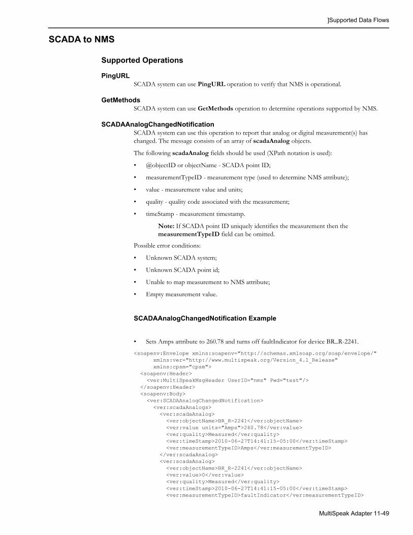
]Supported Data Flows
SCADA to NMS
Supported Operations
PingURLSCADA system can use PingURL operation to verify that NMS is operational.
GetMethodsSCADA system can use GetMethods operation to determine operations supported by NMS.
SCADAAnalogChangedNotificationSCADA system can use this operation to report that analog or digital measurement(s) has changed. The message consists of an array of scadaAnalog objects.
The following scadaAnalog fields should be used (XPath notation is used):
• @objectID or objectName - SCADA point ID;
• measurementTypeID - measurement type (used to determine NMS attribute);
• value - measurement value and units;
• quality - quality code associated with the measurement;
• timeStamp - measurement timestamp.
Note: If SCADA point ID uniquely identifies the measurement then the measurementTypeID field can be omitted.
Possible error conditions:
• Unknown SCADA system;
• Unknown SCADA point id;
• Unable to map measurement to NMS attribute;
• Empty measurement value.
SCADAAnalogChangedNotification Example
• Sets Amps attribute to 260.78 and turns off faultIndicator for device BR_R-2241.
<soapenv:Envelope xmlns:soapenv="http://schemas.xmlsoap.org/soap/envelope/" xmlns:ver="http://www.multispeak.org/Version_4.1_Release" xmlns:cpsm="cpsm"> <soapenv:Header> <ver:MultiSpeakMsgHeader UserID="nms" Pwd="test"/> </soapenv:Header> <soapenv:Body> <ver:SCADAAnalogChangedNotification> <ver:scadaAnalogs> <ver:scadaAnalog> <ver:objectName>BR_R-2241</ver:objectName> <ver:value units="Amps">260.78</ver:value> <ver:quality>Measured</ver:quality> <ver:timeStamp>2010-06-27T14:41:15-05:00</ver:timeStamp> <ver:measurementTypeID>Amps</ver:measurementTypeID> </ver:scadaAnalog> <ver:scadaAnalog> <ver:objectName>BR_R-2241</ver:objectName> <ver:value>0</ver:value> <ver:quality>Measured</ver:quality> <ver:timeStamp>2010-06-27T14:41:15-05:00</ver:timeStamp> <ver:measurementTypeID>faultIndicator</ver:measurementTypeID>
MultiSpeak Adapter 11-49
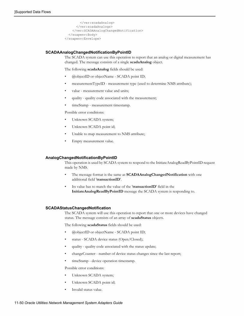
]Supported Data Flows
</ver:scadaAnalog> </ver:scadaAnalogs> </ver:SCADAAnalogChangedNotification> </soapenv:Body></soapenv:Envelope>
SCADAAnalogChangedNotificationByPointIDThe SCADA system can use this operation to report that an analog or digital measurement has changed. The message consists of a single scadaAnalog object.
The following scadaAnalog fields should be used:
• @objectID or objectName - SCADA point ID;
• measurementTypeID - measurement type (used to determine NMS attribute);
• value - measurement value and units;
• quality - quality code associated with the measurement;
• timeStamp - measurement timestamp.
Possible error conditions:
• Unknown SCADA system;
• Unknown SCADA point id;
• Unable to map measurement to NMS attribute;
• Empty measurement value.
AnalogChangedNotificationByPointIDThis operation is used by SCADA system to respond to the InitiateAnalogReadByPointID request made by NMS.
• The message format is the same as SCADAAnalogChangedNotification with one additional field 'transactionID'.
• Its value has to match the value of the 'transactionID' field in the InitiateAnalogReadByPointID message the SCADA system is responding to.
SCADAStatusChangedNotificationThe SCADA system will use this operation to report that one or more devices have changed status. The message consists of an array of scadaStatus objects.
The following scadaStatus fields should be used:
• @objectID or objectName - SCADA point ID;
• status - SCADA device status (Open/Closed);
• quality - quality code associated with the status update;
• changeCounter - number of device status changes since the last report;
• timeStamp - device operation timestamp.
Possible error conditions:
• Unknown SCADA system;
• Unknown SCADA point id;
• Invalid status value.
11-50 Oracle Utilities Network Management System Adapters Guide
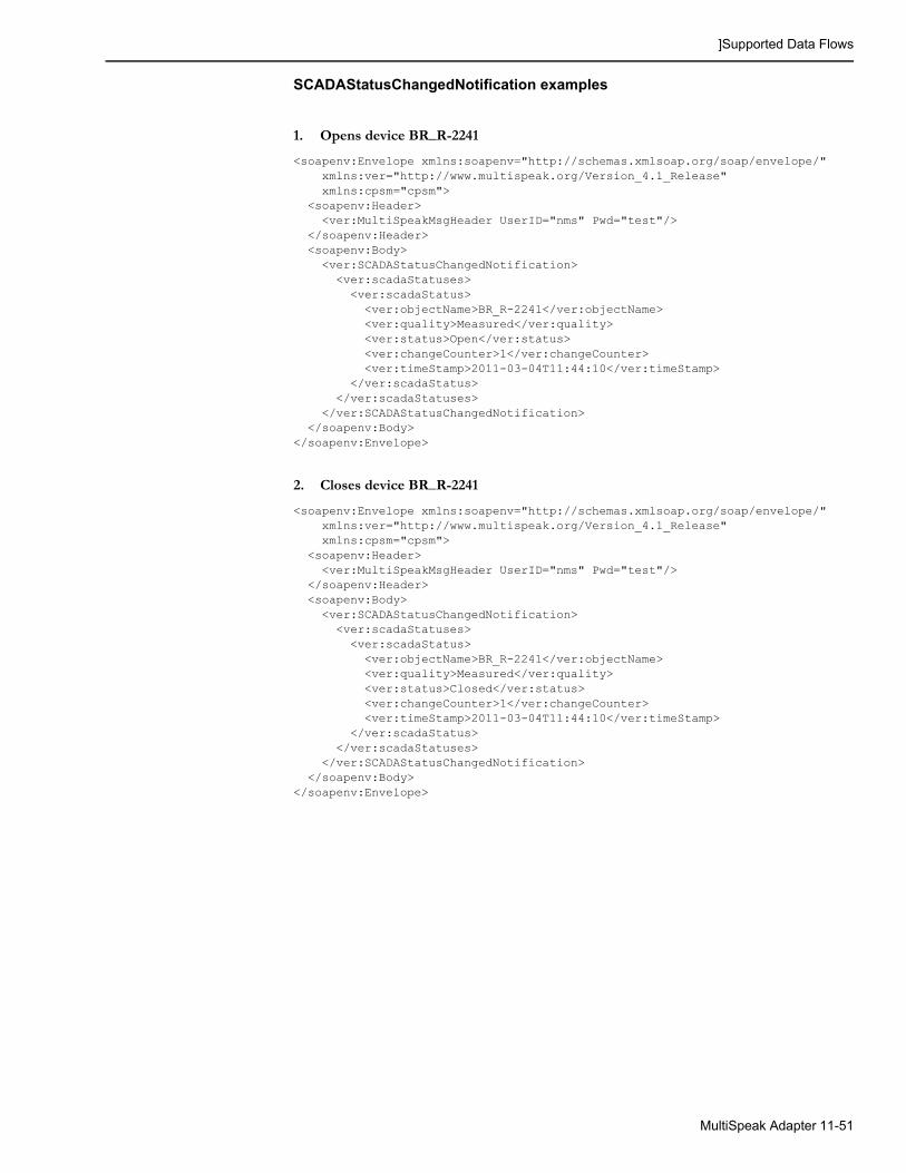
]Supported Data Flows
SCADAStatusChangedNotification examples
1. Opens device BR_R-2241
<soapenv:Envelope xmlns:soapenv="http://schemas.xmlsoap.org/soap/envelope/" xmlns:ver="http://www.multispeak.org/Version_4.1_Release" xmlns:cpsm="cpsm"> <soapenv:Header> <ver:MultiSpeakMsgHeader UserID="nms" Pwd="test"/> </soapenv:Header> <soapenv:Body> <ver:SCADAStatusChangedNotification> <ver:scadaStatuses> <ver:scadaStatus> <ver:objectName>BR_R-2241</ver:objectName> <ver:quality>Measured</ver:quality> <ver:status>Open</ver:status> <ver:changeCounter>1</ver:changeCounter> <ver:timeStamp>2011-03-04T11:44:10</ver:timeStamp> </ver:scadaStatus> </ver:scadaStatuses> </ver:SCADAStatusChangedNotification> </soapenv:Body></soapenv:Envelope>
2. Closes device BR_R-2241
<soapenv:Envelope xmlns:soapenv="http://schemas.xmlsoap.org/soap/envelope/" xmlns:ver="http://www.multispeak.org/Version_4.1_Release" xmlns:cpsm="cpsm"> <soapenv:Header> <ver:MultiSpeakMsgHeader UserID="nms" Pwd="test"/> </soapenv:Header> <soapenv:Body> <ver:SCADAStatusChangedNotification> <ver:scadaStatuses> <ver:scadaStatus> <ver:objectName>BR_R-2241</ver:objectName> <ver:quality>Measured</ver:quality> <ver:status>Closed</ver:status> <ver:changeCounter>1</ver:changeCounter> <ver:timeStamp>2011-03-04T11:44:10</ver:timeStamp> </ver:scadaStatus> </ver:scadaStatuses> </ver:SCADAStatusChangedNotification> </soapenv:Body></soapenv:Envelope>
MultiSpeak Adapter 11-51

]Supported Data Flows
SCADAStatusChangedNotificationByPointIDThe SCADA system can use this operation to report that the status of a device has changed. The message consists of a single scadaStatus object.
The following scadaStatus fields should be used:
• @objectID or objectName - SCADA point ID;
• status - SCADA device status (Open/Closed);
• quality - quality code associated with the status update;
• changeCounter - number of device status changes since the last report;
• timeStamp - device operation timestamp.
Possible error conditions:
• Unknown SCADA system;
• Unknown SCADA point id;
• Invalid status value.
StatusChangedNotificationByPointIDThis operation is used by the SCADA system to respond to the InitiateStatusReadByPointID request made by NMS.
• Message format is the same as SCADAStatusChangedNotification with one additional field 'transactionID'.
• Its value has to match value of the 'transactionID' field in the InitiateStatusReadByPointID message the SCADA system is responding to.
SCADATagChangedNotificationThe SCADA system can use this operation to report that there has been a change in tag(s) placed on devices in the SCADA system. The message consists of an array of scadaTag objects.
The following scadaTag fields should be used:
• @objectID - SCADA tag identifier;
• scadaPointID - SCADA point id;
• @verb - action (New/Change/Delete);
• tagType - SCADA tag type;
• username - SCADA operator's user name;
• comment - tag comments, notes;
• timeStamp - tag operation timestamp.
Possible error conditions:
• Unknown SCADA system;
• Unknown SCADA point id;
• Invalid tag type;
• Unsupported action.
This operation is vendor extension to the MultiSpeak 4.1 specification.
11-52 Oracle Utilities Network Management System Adapters Guide
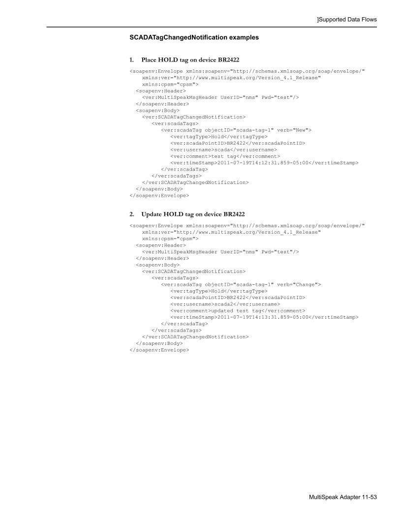
]Supported Data Flows
SCADATagChangedNotification examples
1. Place HOLD tag on device BR2422
<soapenv:Envelope xmlns:soapenv="http://schemas.xmlsoap.org/soap/envelope/" xmlns:ver="http://www.multispeak.org/Version_4.1_Release" xmlns:cpsm="cpsm"> <soapenv:Header> <ver:MultiSpeakMsgHeader UserID="nms" Pwd="test"/> </soapenv:Header> <soapenv:Body> <ver:SCADATagChangedNotification> <ver:scadaTags> <ver:scadaTag objectID="scada-tag-1" verb="New"> <ver:tagType>Hold</ver:tagType> <ver:scadaPointID>BR2422</ver:scadaPointID> <ver:username>scada</ver:username> <ver:comment>test tag</ver:comment> <ver:timeStamp>2011-07-19T14:12:31.859-05:00</ver:timeStamp> </ver:scadaTag> </ver:scadaTags> </ver:SCADATagChangedNotification> </soapenv:Body></soapenv:Envelope>
2. Update HOLD tag on device BR2422
<soapenv:Envelope xmlns:soapenv="http://schemas.xmlsoap.org/soap/envelope/" xmlns:ver="http://www.multispeak.org/Version_4.1_Release" xmlns:cpsm="cpsm"> <soapenv:Header> <ver:MultiSpeakMsgHeader UserID="nms" Pwd="test"/> </soapenv:Header> <soapenv:Body> <ver:SCADATagChangedNotification> <ver:scadaTags> <ver:scadaTag objectID="scada-tag-1" verb="Change"> <ver:tagType>Hold</ver:tagType> <ver:scadaPointID>BR2422</ver:scadaPointID> <ver:username>scada2</ver:username> <ver:comment>updated test tag</ver:comment> <ver:timeStamp>2011-07-19T14:13:31.859-05:00</ver:timeStamp> </ver:scadaTag> </ver:scadaTags> </ver:SCADATagChangedNotification> </soapenv:Body></soapenv:Envelope>
MultiSpeak Adapter 11-53
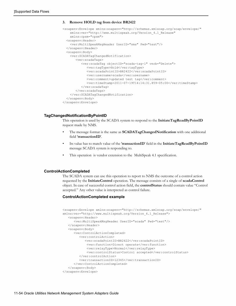
]Supported Data Flows
3. Remove HOLD tag from device BR2422
<soapenv:Envelope xmlns:soapenv="http://schemas.xmlsoap.org/soap/envelope/" xmlns:ver="http://www.multispeak.org/Version_4.1_Release" xmlns:cpsm="cpsm"> <soapenv:Header> <ver:MultiSpeakMsgHeader UserID="nms" Pwd="test"/> </soapenv:Header> <soapenv:Body> <ver:SCADATagChangedNotification> <ver:scadaTags> <ver:scadaTag objectID="scada-tag-1" verb="Delete"> <ver:tagType>Hold</ver:tagType> <ver:scadaPointID>BR2422</ver:scadaPointID> <ver:username>scada</ver:username> <ver:comment>updated test tag</ver:comment> <ver:timeStamp>2011-07-19T14:14:31.859-05:00</ver:timeStamp> </ver:scadaTag> </ver:scadaTags> </ver:SCADATagChangedNotification> </soapenv:Body></soapenv:Envelope>
TagChangedNotificationByPointIDThis operation is used by the SCADA system to respond to the InitiateTagReadByPointID request made by NMS.
• The message format is the same as SCADATagChangedNotification with one additional field 'transactionID'.
• Its value has to match value of the 'transactionID' field in the InitiateTagReadByPointID message SCADA system is responding to.
• This operation is vendor extension to the MultiSpeak 4.1 specification.
ControlActionCompletedThe SCADA system can use this operation to report to NMS the outcome of a control action requested by the InitiateControl operation. The message consists of a single of scadaControl object. In case of successful control action field, the controlStatus should contain value “Control accepted.” Any other value is interpreted as control failure.
ControlActionCompleted example
<soapenv:Envelope xmlns:soapenv="http://schemas.xmlsoap.org/soap/envelope/" xmlns:ver="http://www.multispeak.org/Version_4.1_Release"> <soapenv:Header> <ver:MultiSpeakMsgHeader UserID="scada" Pwd="test"/> </soapenv:Header> <soapenv:Body> <ver:ControlActionCompleted> <ver:controlAction> <ver:scadaPointID>BR2422</ver:scadaPointID> <ver:function>Direct operate</ver:function> <ver:relayType>Normal</ver:relayType> <ver:controlStatus>Control accepted</ver:controlStatus> </ver:controlAction> <ver:transactionID>12345</ver:transactionID> </ver:ControlActionCompleted> </soapenv:Body></soapenv:Envelope>
11-54 Oracle Utilities Network Management System Adapters Guide

]Supported Data Flows
VoltageAlarmNotificationThe SCADA system can use this operation to report alarms to NMS. The message consists of an array of voltageAlarm objects.
The following voltageAlarm fields should be used:
• @objectID - SCADA alarm identifier;
• sourceIdentifier - SCADA point id;
• sourceIdentifier/@name - attribute name;
• @verb - action (only New is allowed);
• @errorString - alarm description;
• comments - alarm description;
• eventTime - SCADA alarm timestamp;
• voltageAlarmList/voltageAlarmItem[1]/voltageValue - SCADA measurement value, which caused the alarm;
• voltageAlarmList/voltageAlarmItem[1]/quality - SCADA quality code;
• voltageAlarmList/voltageAlarmItem[1]/analogCondition - SCADA limit violation;
• voltageAlarmList/voltageAlarmItem[1]/phaseCode - SCADA alarm phases.
For alarms SCADA quality code is passed “as-is.” Configured quality code mapping rules are not applied in this case.
Possible error conditions:
• Unknown SCADA system;
• Unknown SCADA point id;
• Unsupported action.
VoltageAlarmNotification Example
<soapenv:Envelope xmlns:soapenv="http://schemas.xmlsoap.org/soap/envelope/" xmlns:ver="http://www.multispeak.org/Version_4.1_Release" xmlns:cpsm="cpsm"> <soapenv:Header> <ver:MultiSpeakMsgHeader UserID="nms1" Pwd="systems"/> </soapenv:Header> <soapenv:Body> <ver:VoltageAlarmNotification> <ver:alarms> <ver:voltageAlarm objectID="alarm-1" verb="New" errorString="alarm test"> <ver:comments>comment</ver:comments> <ver:sourceIdentifier name="Volts">BR2422</ver:sourceIdentifier> <ver:eventTime>2011-05-11T10:05:25.484-05:00</ver:eventTime> <ver:voltageAlarmList> <ver:voltageAlarmItem> <ver:voltageValue units="V">100</ver:voltageValue> <ver:quality>Measured</ver:quality> <ver:analogCondition>H1</ver:analogCondition> <ver:phaseCode>BC</ver:phaseCode> </ver:voltageAlarmItem> </ver:voltageAlarmList> </ver:voltageAlarm> </ver:alarms> </ver:VoltageAlarmNotification> </soapenv:Body></soapenv:Envelope>
MultiSpeak Adapter 11-55
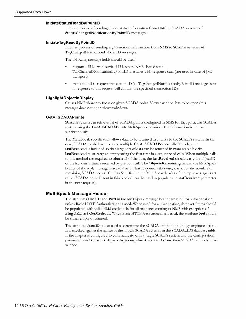
]Supported Data Flows
InitiateStatusReadByPointIDInitiates process of sending device status information from NMS to SCADA as series of StatusChangedNotificationByPointID messages.
InitiateTagReadByPointIDInitiates process of sending tag/condition information from NMS to SCADA as series of TagChangedNotificationByPointID messages.
The following message fields should be used:
• responseURL - web service URL where NMS should send TagChangedNotificationByPointID messages with response data (not used in case of JMS transport)
• transactionID - request transaction ID (all TagChangedNotificationByPointID messages sent in response to this request will contain the specified transaction ID)
HighlightObjectInDisplayCauses NMS viewer to focus on given SCADA point. Viewer window has to be open (this message does not open viewer window).
GetAllSCADAPointsSCADA system can retrieve list of SCADA points configured in NMS for that particular SCADA system using the GetAllSCADAPoints MultiSpeak operation. The information is returned synchronously.
The MultiSpeak specification allows data to be returned in chunks to the SCADA system. In this case, SCADA would have to make multiple GetAllSCADAPoints calls. The element lastReceived is included so that large sets of data can be returned in manageable blocks. lastReceived must carry an empty string the first time in a sequence of calls. When multiple calls to this method are required to obtain all of the data, the lastReceived should carry the objectID of the last data instance received by previous call. The ObjectsRemaining field in the MultiSpeak header of the reply message is set to 0 in the last response; otherwise, it is set to the number of remaining SCADA points. The LastSent field in the MultiSpeak header of the reply message is set to last SCADA point id sent in this block (it can be used to populate the lastReceived parameter in the next request).
MultiSpeak Message HeaderThe attributes UserID and Pwd in the MultiSpeak message header are used for authentication unless Basic HTTP Authentication is used. When used for authentication, these attributes should be populated with valid NMS credentials for all messages coming to NMS with exception of PingURL and GetMethods. When Basic HTTP Authentication is used, the attribute Pwd should be either empty or omitted.
The attribute UserID is also used to determine the SCADA system the message originated from. It is checked against the names of the known SCADA systems in the SCADA_IDS database table. If the adapter is configured to communicate with a single SCADA system and the configuration parameter config.strict_scada_name_check is set to false, then SCADA name check is skipped.
11-56 Oracle Utilities Network Management System Adapters Guide

Software Configuration
Software ConfigurationConfiguration for the Oracle Utilities Network Management System MultiSpeak Adapter comes from the following sources:
• CES_PARAMETERS database table;
• SCADA_IDS database table;
• SCADA_LINKS database table;
• SCADA_LINK_OPS database table;
• SCADA_SYNONYMS database table.
CES_PARAMETERSEntries in the CES_PARAMETERS database table for the SCADA component of the Oracle Utilities Network Management System MultiSpeak Adapter should have the value SCADAInterface in the APP column. Column ATTRIB should contain the name of the configuration parameter and column VALUE its value. See Overriding Configuration Parameters on page 11-17 for more information.
Common Configuration ParametersThe following table describes the common configuration parameters.
Parameter Description
config.credentials Absolute path to the file containing user credentials the adapter will use to communicate with Oracle Utilities Network Management System.Either this parameter or both config.username and config.password parameters should be provided. If all are present then config.username/config.password pair is used.
config.enabled Enables SCADA processing.
Default: false
config.message_credentials_required
If this parameter is set to false then credentials for authenticating with NMS are taken from the MultiSpeak header of the incoming message.If this parameter is set to false and credentials are not present in the MultiSpeak header of the incoming message then username and password configured in the adapter is used to authenticate with NMS.
Valid Values: true|false.
Default: true
config.password NMS user password. Value of this parameter should be encrypted.
MultiSpeak Adapter 11-57

Software Configuration
Per SCADA System Configuration ParametersThe following configuration parameters are configured individually for each SCADA system the adapter is communicating with. Names of such parameters are prefixed with the name of the SCADA system they apply to (value from the SCADA_NAME column in the SCADA_IDS table).
Authentication with the SCADA System The SCADA component of the Oracle Utilities Network Management System MultiSpeak Adapter passes credentials to the SCADA system in the UserID and Pwd fields of the MultiSpeak message header.
Note: Other MultiSpeak message header fields can be set by using desired field name in the parameter name.
config.nms_url URL for accessing Oracle Utilities Network Management System. If this parameter is not provided then it is assumed that MultiSpeak Adapter is deployed on the same Managed Server as cesejb.ear.This parameter is specified for each component of the adapter, but only one value is actually used; all components will connect to the same NMS instance. The value is taken from the first enabled component according to the following order of precedence:1. SCADA
2. AMR
3. AVL
Note: This parameter replaces the Foreign JNDI configuration used in earlier versions of the Adapter.
config.strict_scada_name_check SCADA name validation. If set to 'false' and only one SCADA system is configured for the MultiSpeak Adapter in the SCADA_IDS database table then SCADA name check is skipped. Otherwise field UserID in the MultiSpeak message header or username of the web services caller (if UserID is empty) is matched against the values in the SCADA_NAME field in the SCADA_IDS database table. Request is rejected if matched value is not found.
Default: true
config.username Valid NMS username, which has the 'NmsService' role in WebLogic Server.
Parameter Description
Parameter Description
<scada name>.headers.UserID Username to be passed to the SCADA system.
<scada name>.headers.Pwd Password to be passed to the SCADA system.
11-58 Oracle Utilities Network Management System Adapters Guide

Software Configuration
JNDI Name for JMS Connection FactoryWhen JMS transport is used this parameter defines JNDI name of the JMS connection factory used for NMS to SCADA data flows.
JMS Connection CredentialsThese parameters are used if credentials are required to establish connection to JMS server. They are passed to the createConnection method of JMS connection factory.
SCADA System Plugin ClassPlugin class is a Java class, which encapsulates functionality of the adapter, which is specific to a particular SCADA system.
Support for TagsThese parameters control tag-related data flows.
Parameter Description
<scada name>.jms_cf_name JNDI name of the JMS connection factory which should be used for NMS to SCADA data flows.
Default: ConnectionFactory
Parameter Description
<scada name>.jms_user JMS connection username.
<scada name>.jms_password JMS connection password.
Parameter Description
<scada name>.plugin_class Full name of the Java class implementing ScadaSystemPlugin interface for the SCADA system the adapter is connected to.
Default: com.splwg.oms.interfaces.scada.plugins.GenericScada
Parameter Description
<scada name>.support_tags Enable/disable support for incoming tags.
Default: false (incoming tags are not supported)
<scada name>.outgoing_tag.class.<idx>
Names of the NMS condition classes for which updates should be sent to the SCADA system. This applies to the children of the configured classes as well.
<scada name>.outgoing_tag.block_size
Block size for the outgoing condition messages.
Default: 10
<scada name>.outgoing_tag.only_scada
Only send outgoing tag messages for SCADA devices. If set to 'true' only tags on SCADA devices will be reported to SCADA; otherwise, tags on all devices are reported.
Default: false
MultiSpeak Adapter 11-59

Software Configuration
<idx> - suffix used to make parameter name unique; any value can be used as long as resulting configuration parameter name is unique.
Synchronization Sequence TimeoutThis parameter limits how long synchronization sequence can last. If this value is exceeded then link failure is declared.
Automatic Synchronization of Measurements ValuesSCADA systems can have large number of analog measurements and synchronizing those can be a lengthy task. This configuration parameter allows analog measurements to be excluded from automated synchronization sequence, which is executed when connection to SCADA system is established.
It is always possible to manually trigger synchronization of analog measurements regardless of the value of this parameter.
Adapter Status Alarm MessagesNMS MultiSpeak adapter can generate system alarms to alert NMS operator about following conditions:
• Adapter has been started
• Adapter has been stopped
• Connection to SCADA system has been established
• Connection to SCADA system has failed
• Synchronization sequence has finished
<scada name>.outgoing_tag.add_gang_point
When tag is placed on a phase-operable device send outgoing tag message for the point representing all device phases. This message is sent in addition to the messages for points representing individual tagged phases which are always sent.
Default: false
Parameter Description
Parameter Description
<scada name>.sync_timeout Maximum allowed duration (in seconds) of synchronization sequence.
Default: 3600
Parameter Description
<scada name>.sync_analogs Include measurement values into automated synchronization sequence.
Default: true
Parameter Description
<scada name>.msg.started Text of the alarm generated when adapter has been started.
<scada name>.msg.stopped Text of the alarm generated when adapter has been stopped.
11-60 Oracle Utilities Network Management System Adapters Guide

Software Configuration
If alarm text is not configured then corresponding alarm will not be generated.
Dynamic SCADA Point ConfigurationWhen SCADA system has knowledge of NMS device aliases or device handles it is possible to have process of SCADA point configuration to be performed by the adapter as part of integrity check. New SCADA points are added to the database tables ANALOG_MEASUREMENTS, DIGITAL_MEASUREMENTS and SCADA_MEASUREMENTS_ST. Orphaned SCADA points can be removed from the SCADA_MEASUREMENTS_ST database table.
No additional actions are required for new SCADA points to take effect (users may have to refresh SCADA Summary to see new points). Command 'UpdateDDS -recacheMeasures' need to be executed to propagate record deletions to runtime tables (ANALOG_MEASUREMENTS and DIGITAL_MEASUREMENTS).
In order for dynamic SCADA point configuration to be possible SCADA system plugin must implement buildScadaPointId and parseScadaPointId methods.
Sending Device Status Information from NMS to SCADAThe adapter can be configured to send NMS device status information to SCADA system. List of NMS devices classes has to be configured to enable this functionality (<scada name>.outgoing_status.class.<idx> parameter).
Class inheritance is taken into account so if a device class is configured to have status changes to be sent to SCADA system then status changes for all the child classes would also be sent out.
For conductors quality value in the outgoing message is set to Other. In all other cases quality value is not set.
Status information for inline jumpers is reported as status on the underlying conductor.
<scada name>.msg.established Text of the alarm generated when connection to SCADA system has been established.
<scada name>.msg.failed Text of the alarm generated when connection to SCADA system has failed.
<scada name>.msg.synchronized
Text of the alarm generated when synchronization sequence has finished.
Parameter Description
Parameter Description
<scada name>.dynamic_point_config
Dynamic SCADA point configuration support.Valid values:
• full – dynamic addition and removal of SCADA points is supported
• add – only dynamic addition of SCADA points is supported
• none – not supported
Default: none.
MultiSpeak Adapter 11-61

Software Configuration
Point-to-point jumpers are not supported.
<idx> - suffix used to make parameter name unique; any value can be used as long as resulting configuration parameter name is unique.
Synchronization MethodThe SCADA component of the Oracle Utilities Network Management System MultiSpeak Adapter supports two methods of synchronizing device statuses and measurements with the SCADA system: synchronous and asynchronous.
Parameter Description
<scada name>.outgoing_status.class.<idx>
Device classes for which status information should be sent to SCADA system.
<scada name>.outgoing_status.block_size
Block size for outgoing device status messages.Default: 10
<scada name>.outgoing_status.allow_scada
Allow device status updates for SCADA devices to be sent to the SCADA system. This is disabled by default because SCADA system is the master for the information about SCADA devices.Default: false
<scada name>.outgoing_status.allow_pending_construction
Allow device status updates for pending construction devices as well as changes in pending construction status of devices to be sent to the SCADA system.Default: false
<scada name>.conductor.class.<idx>
NMS conductor device classes.
<scada name>.jumper.class.<idx>
NMS jumper device classes.
Parameter Description
<scada name>.preferred_sync_method
Preferred method of synchronization with the SCADA system.Valid values:
• sync – synchronous
• async - asynchronous
Default: async.
<scada name>.need_sync_points
Whether full list of SCADA points known to NMS should be sent to SCADA during synchronization process. Only applicable when preferred_sync_method is async.
Valid Values: true|false
Default: false
11-62 Oracle Utilities Network Management System Adapters Guide

Software Configuration
SOAP Protocol VersionOracle Utilities Network Management System MultiSpeak Adapter can use SOAP protocol versions 1.1 or 1.2.
Outbound ControlsThe SCADA component of the Oracle Utilities Network Management System MultiSpeak Adapter supports sending control requests to the SCADA system.
Heartbeat IntervalThe SCADA component of the Oracle Utilities Network Management System MultiSpeak Adapter periodically sends PingURL message to the SCADA system to check status of the link. Heartbeat failure causes adapter to switch to alternate link (if available).
Support for Operating Non-SCADA Devices in the NMS ModelIf set to 'true' this configuration parameter allows SCADA system to operate devices, which are not SCADA-telemetered, in NMS model. For this to be possible the adapter must be able to derive NMS device handle from SCADA point id. In addition if dynamic point configuration is
Parameter Description
<scada name>.soap12 Whether SOAP 1.2 should be used.
Valid Values: • true: use SOAP 1.2.
• false: use SOAP 1.1
Default: false
Parameter Description
<scada name>.allow_controls Whether control requests should be sent to SCADA.Valid values: true/false
Default: false (controls are not allowed)
<scada name>.allow_multiphase_controls
Allows sending of a single control request when all phases of a phase-operable device are operated.
Default: false (for phase-operable devices, a separate control request is sent for each phase).
Parameter Description
<scada name>.heartbeat_interval
Interval in seconds between heartbeat messages.
Default: 60 seconds
MultiSpeak Adapter 11-63
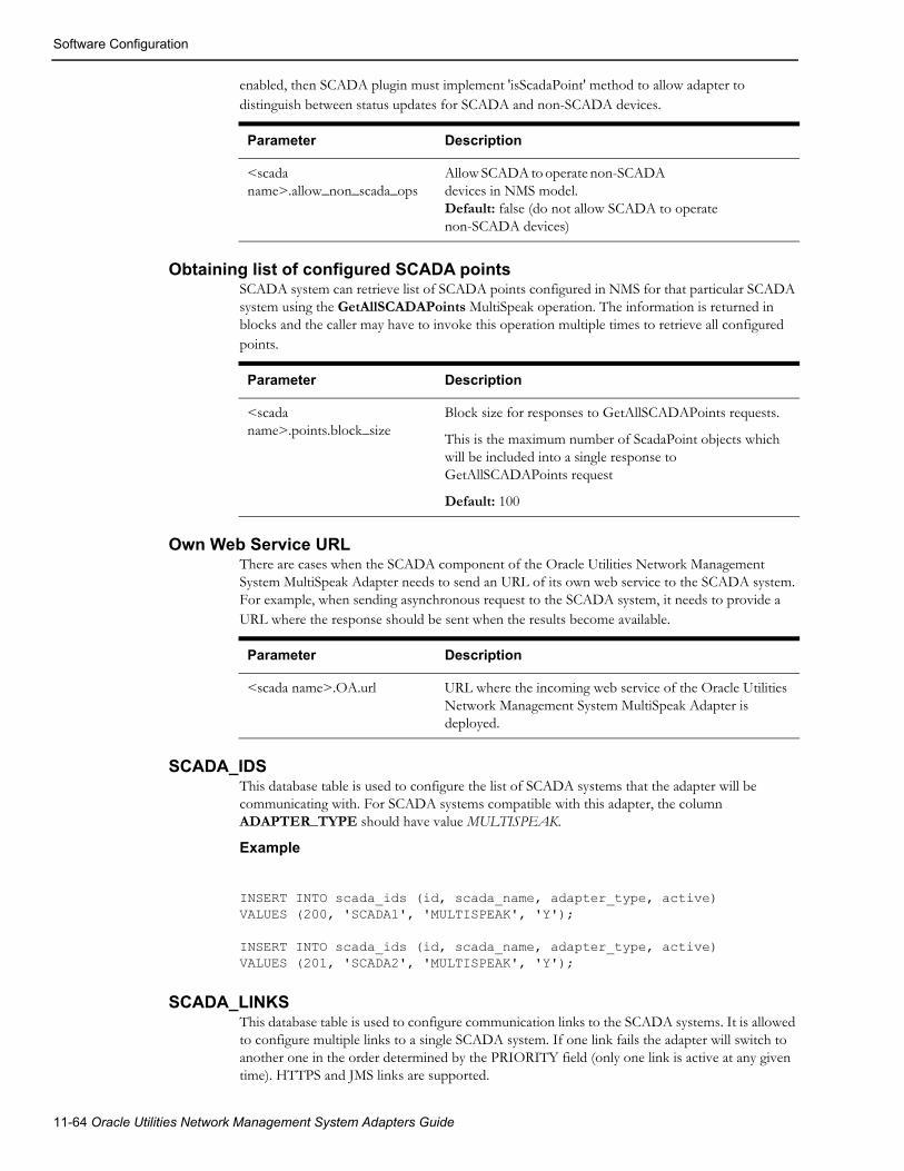
Software Configuration
enabled, then SCADA plugin must implement 'isScadaPoint' method to allow adapter to distinguish between status updates for SCADA and non-SCADA devices.
Obtaining list of configured SCADA pointsSCADA system can retrieve list of SCADA points configured in NMS for that particular SCADA system using the GetAllSCADAPoints MultiSpeak operation. The information is returned in blocks and the caller may have to invoke this operation multiple times to retrieve all configured points.
Own Web Service URLThere are cases when the SCADA component of the Oracle Utilities Network Management System MultiSpeak Adapter needs to send an URL of its own web service to the SCADA system. For example, when sending asynchronous request to the SCADA system, it needs to provide a URL where the response should be sent when the results become available.
SCADA_IDSThis database table is used to configure the list of SCADA systems that the adapter will be communicating with. For SCADA systems compatible with this adapter, the column ADAPTER_TYPE should have value MULTISPEAK.
Example
INSERT INTO scada_ids (id, scada_name, adapter_type, active)VALUES (200, 'SCADA1', 'MULTISPEAK', 'Y');
INSERT INTO scada_ids (id, scada_name, adapter_type, active)VALUES (201, 'SCADA2', 'MULTISPEAK', 'Y');
SCADA_LINKSThis database table is used to configure communication links to the SCADA systems. It is allowed to configure multiple links to a single SCADA system. If one link fails the adapter will switch to another one in the order determined by the PRIORITY field (only one link is active at any given time). HTTPS and JMS links are supported.
Parameter Description
<scada name>.allow_non_scada_ops
Allow SCADA to operate non-SCADA devices in NMS model. Default: false (do not allow SCADA to operate non-SCADA devices)
Parameter Description
<scada name>.points.block_size
Block size for responses to GetAllSCADAPoints requests.
This is the maximum number of ScadaPoint objects which will be included into a single response to GetAllSCADAPoints request
Default: 100
Parameter Description
<scada name>.OA.url URL where the incoming web service of the Oracle Utilities Network Management System MultiSpeak Adapter is deployed.
11-64 Oracle Utilities Network Management System Adapters Guide

Software Configuration
• For HTTP links, the WS_URL column is used to specify the URL of the SCADA system web service.
• For JMS links, the columns REQUEST_QUEUE and RESPONSE_QUEUE are used to specify the JNDI names of the JMS queues used to send requests to and receive responses from the SCADA system.
• The value in the TIMEOUT column controls how long the adapter should wait for a response from the SCADA system (in seconds). This is only applicable to JMS links. The maximum allowed value is 3600 (1 hour).
• The value in the PERSISTENT column defines the delivery mode for JMS messages. If set to 'Y' then JMS messages are persistent, otherwise they are not persistent. By default messages are not persistent. This is only applicable to JMS links.
Example
INSERT INTO scada_links (id, scada_id, ws_url, timeout, priority, active)VALUES (1, 200, 'http://scada-server1:8088/SCADA', 30, 1, 'Y');INSERT INTO scada_links (id, scada_id, ws_url, timeout, priority, active)VALUES (2, 200, 'http://scada-server2:8088/SCADA', 30, 2, 'Y');INSERT INTO scada_links (id, scada_id, request_queue, response_queue, timeout, persistent, priority, active)VALUES (3, 200, 'queue/ScadaRequest', 'queue/ScadaResponse', 30, 'N', 3, 'Y');
SCADA_LINK_OPSThis table can be used to configure communication parameters differently for individual outgoing web service operations. If an operation does not have a record in the SCADA_LINK_OPS table then values from the parent SCADA_LINKS record are used.
Column LINK_ID is the foreign key into the SCADA_LINKS table.
Column OPERATION is used to specify web service operation name. Supported operation names:
• PingURL
• GetMethods
• InitiateAnalogReadByPointID
• InitiateStatusReadByPointID
• InitiateTagReadByPointID
• InitiateControl
• GetAllSCADAAnalogs
• GetAllSCADAStatus
• GetAllSCADATags
• SCADAStatusChangedNotification
• SCADAStatusChangedNotificationByPointID
• StatusChangedNotificationByPointID
• HighlightObjectInDisplay
• SCADATagChangedNotification
• TagChangedNotificationByPointID
MultiSpeak Adapter 11-65

Software Configuration
For HTTP links, the WS_URL column is used to specify the URL of the SCADA system web service. For JMS links, the columns REQUEST_QUEUE and RESPONSE_QUEUE are used to specify the JNDI names of the JMS queues used to send requests to and receive responses from the SCADA system.
Value in the TIMEOUT column controls how long the adapter should wait for response from SCADA system (in seconds). Maximum allowed value is 3600 (1 hour).
Value in the PERSISTENT column defines delivery mode for JMS messages. If set to 'Y' then JMS messages are persistent, otherwise they are not persistent. By default messages are not persistent.
Example
INSERT INTO scada_link_ops (id, link_id, operation, request_queue, response_queue, timeout, persistent)VALUES (31, 3, 'PingURL', 'queue/ScadaRequest_PingURL', 'queue/ScadaResponse_PingURL', 30, 'N');INSERT INTO scada_link_ops (id, link_id, operation, ws_url, timeout, persistent)VALUES (32, 4, 'GetMethods', 'http://scada-server:8080/GetMethods', 30, 'N');
SCADA_SYNONYMSThis database table is used configure mapping of different data elements between SCADA and NMS systems. The SCADA_ID column should always be populated with the id of the SCADA system (value of the ID column in the SCADA_IDS table) the mapping applies to.
Device Status MappingBy default the adapter maps MultiSpeak device status values 'Open' and 'Closed' to the corresponding device statuses in NMS and ignores all other device status values defined by MultiSpeak 4.1 specification. SCADA_SYNONYMS table allows customization of device status mapping by associating MultiSpeak device status value to a combination of NMS device status and quality code.
The MultiSpeak device status value should be entered into the KEYWORD column. The NMS device status value should be entered into the STATUS_VALUE column. Valid values are 'Open', 'Closed' or NULL.
If this column is NULL, the device status in NMS will not be affected.
The NMS quality code should be entered in the INT_VALUE column. It will be combined with the quality code received in the MultiSpeak message. The PROCESS_TYPE should be 'S'.
The following example maps the 'Travel' device status received from SCADA to quality code 8192 and keeps device status in NMS unchanged.
INSERT INTO scada_synonyms (id, scada_id, keyword, status_value, int_value, process_type)VALUES (tmp_seq.nextval, 200, 'Travel', null, 262144, 'S');
11-66 Oracle Utilities Network Management System Adapters Guide

Software Configuration
Attribute MappingAttribute mapping is used when SCADA point ID does not uniquely identify both NMS device and attribute. SCADA attribute name/key should be entered into the KEYWORD column. NMS attribute key should be entered into the INT_VALUE column. PROCESS_TYPE should be 'D' for digital measurements and 'A' for analogs.
Example
INSERT INTO scada_synonyms (id, scada_id, keyword, int_value, process_type)VALUES (1, 200, 'faultIndicator', 23, 'D');INSERT INTO scada_synonyms (id, scada_id, keyword, int_value, process_type)VALUES (2, 200, 'Amps', 1012, 'A');
An additional method for configuring mapping for digital measurements is available. It applies specifically to the case when digital measurement is submitted to NMS via SCADAStatusChangedNotification, SCADAStatusChangedNotificationByPointID or StatusChangedNotificationByPointID operation. This is only possible when SCADA point id uniquely identifies digital measurement in NMS.
SCADA attribute name/key should be entered into the KEYWORD column.
NMS attribute name should be entered into ATTRIBUTE_ALIAS column.
Status value received from SCADA should be entered into STATUS_VALUE column.
Corresponding NMS attribute value should be entered into INT_VALUE column.
PROCESS_TYPE should be 'D'.
Column VALUE is not used.
Example configuration for AutoReclose digital attribute. Receiving status 'Open' from SCADA would set AutoReclose attribute for a device to 1. Receiving status 'Closed' from SCADA would set AutoReclose attribute for a device to 0.
INSERT INTO scada_synonyms (id, scada_id, keyword, int_value, process_type, attribute_alias, status_value, value)VALUES (247, 200, 'AutoReclose', 1, 'D', 'AutoReclose', 'Open', 'On');INSERT INTO scada_synonyms (id, scada_id, keyword, int_value, process_type, attribute_alias, status_value, value)VALUES (248, 200, 'AutoReclose', 0, 'D', 'AutoReclose', 'Closed', 'Off');
MultiSpeak Adapter 11-67
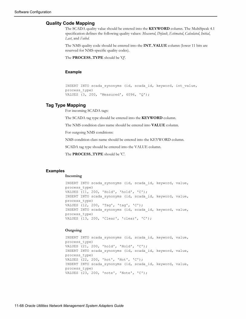
Software Configuration
Quality Code MappingThe SCADA quality value should be entered into the KEYWORD column. The MultiSpeak 4.1 specification defines the following quality values: Measured, Default, Estimated, Calculated, Initial, Last, and Failed.
The NMS quality code should be entered into the INT_VALUE column (lower 11 bits are reserved for NMS-specific quality codes).
The PROCESS_TYPE should be 'Q'.
Example
INSERT INTO scada_synonyms (id, scada_id, keyword, int_value, process_type)VALUES (3, 200, 'Measured', 4096, 'Q');
Tag Type MappingFor incoming SCADA tags:
The SCADA tag type should be entered into the KEYWORD column.
The NMS condition class name should be entered into VALUE column.
For outgoing NMS conditions:
NMS condition class name should be entered into the KEYWORD column.
SCADA tag type should be entered into the VALUE column.
The PROCESS_TYPE should be 'C'.
ExamplesIncoming
INSERT INTO scada_synonyms (id, scada_id, keyword, value, process_type)VALUES (11, 200, 'Hold', 'hold', 'C');INSERT INTO scada_synonyms (id, scada_id, keyword, value, process_type)VALUES (12, 200, 'Tag', 'tag', 'C');INSERT INTO scada_synonyms (id, scada_id, keyword, value, process_type)VALUES (13, 200, 'Clear', 'clear', 'C');
Outgoing
INSERT INTO scada_synonyms (id, scada_id, keyword, value, process_type)VALUES (21, 200, 'hold', 'Hold', 'C');INSERT INTO scada_synonyms (id, scada_id, keyword, value, process_type)VALUES (22, 200, 'hot', 'Hot', 'C');INSERT INTO scada_synonyms (id, scada_id, keyword, value, process_type)VALUES (23, 200, 'note', 'Note', 'C');
11-68 Oracle Utilities Network Management System Adapters Guide

Software Configuration
DDService Configuration for Outbound ControlsThe SCADA component of the Oracle Utilities Network Management System MultiSpeak Adapter periodically polls the database table EXPECTED_ACTIONS for pending SCADA controls.
DDService only write records into this table when it is running with the '-sendAsyncSCADA' command-line option.
SCADA Point ConfigurationThe SCADA component of the Oracle Utilities Network Management System MultiSpeak Adapter loads SCADA point configuration from the ANALOG_MEASUREMENTS and DIGITAL_MEASUREMENTS database tables. It normally happens during initialization. The adapter can be forced to reload the SCADA point configuration during runtime using the following command:
Action -java multispeak.SCADA reloadThe synchronization sequence will be automatically started after the SCADA point configuration is reloaded.
SCADA Configuration for Bellwether MetersIn order for the reading from bellwether meters to be reflected in NMS they need to be configured as SCADA measurements in the SCADA component of the NMS MultiSpeak adapter. The following set of steps should be used to perform such configuration.
1. Add entry to the SCADA_IDS table. The entry should match the 'config.bellwether_scada_name' configuration parameter of the AMR component of the NMS MultiSpeak adapter.
2. Add entries to the SCADA_MEASUREMENT_ST table for the measurement values coming from bellwether meters. The RTI_ALIAS field must be populated using format "<meter id>-<field name>", where <meter id> is the NMS meter identifier (AMR_CU_METERS.METER_ID) and <field name> is the meter reading field name coming from the AMR system (e.g., “Voltage”).
3. Populate SCADA_SYNONYMS table with attribute mappings.
4. Populate SCADA_SYNONYMS table with quality code mappings. The quality code for meter readings is always “Measured.”
Note: Do not populate SCADA_LINKS table to indicate that this is "input-only" SCADA system. It will prevent MultiSpeak adapter from attempting to send heartbeat requests to the AMR system.
MultiSpeak Adapter 11-69

Plugin Support
Plugin SupportSCADA vendors may interpret MultiSpeak specification differently or use extensions, which are unique to each vendor. To address the issue of possible differences between various SCADA components, the NMS MultiSpeak adapter has a plugin interface.
Plugin is a Java class, which encapsulates functionality specific to a particular SCADA system. Plugin class must implement the interface com.splwg.oms.interfaces.scada.ScadaSystemPlugin.
Default implementation of the SCADA system plugin is provided by the com.splwg.oms.interfaces.scada.plugins.GenericScada class.
MethodsThe available plugin methods, including description of how the default plugin class implements each method, are:
getScadaPointIdjava.lang.String getScadaPointId(MspObject obj)
This method is used to extract SCADA Point ID from the incoming MultiSpeak message.
Parameters:
obj - MultiSpeak object
Returns:
SCADA Point ID
Default implementation:
Returns value of the objectID attribute if not empty, otherwise value of the objectName element
getScadaPointIdjava.lang.String getScadaPointId(ScadaTag tag)
This method is used to extract SCADA Point ID from the incoming tag-related MultiSpeak message.
Parameters:
tag - ScadaTag object
Returns:
SCADA Point ID
Default implementation:
Returns value of the scadaPointID element
11-70 Oracle Utilities Network Management System Adapters Guide

Plugin Support
setScadaPointIdvoid setScadaPointId(ScadaTag tag, java.lang.String pointId)This method is used to set SCADA Point ID in the outgoing tag update message.
Parameters:
tag - ScadaTag object to be updated
pointId - SCADA Point ID
Default implementation:
Sets value of the scadaPointID element.
getStatusStatusIdentifiers getStatus(final ScadaStatus status);
This method is used to extract device status value from the MultiSpeak device status update message.
Parameters:
status - ScadaStatus object
Returns:
MultiSpeak device status value
Default implementation:
Returns value of the status element.
getQualityCodesjava.util.List<java.lang.String> getQualityCodes(ScadaStatus status)
This method is used to extract quality values from MultiSpeak status update message.
Parameters:
status - ScadaStatus object
Returns:
list of MultiSpeak quality values
Default implementation:
Returns value of the quality element
getQualityCodesjava.util.List<java.lang.String> getQualityCodes(ScadaAnalog analog)
This method is used to extract quality values from MultiSpeak analog update message.
Parameters:
analog - ScadaAnalog object
Returns:
list of MultiSpeak quality values
Default implementation:
Returns value of the quality element
MultiSpeak Adapter 11-71

Plugin Support
processChangeCounterint processChangeCounter(StatusPoint point, int changeCounter)
This method is used to process SCADA change counter value.
Parameters:
point - SCADA status point
changeCounter - new change counter value for the SCADA status point
Returns:
Number of device operations, which occurred since the last processed update
Default implementation:
Assumes that change counter value received from SCADA is cumulative (total number of times device has changed state since some point in the past). Number of device operations is calculated as the difference between previous and current SCADA change counter values
getTagIdjava.lang.String getTagId(ScadaTag tag)
This method is used to extract value from the tag update message, which is then used to populate external id of the corresponding condition in NMS. This value has to uniquely identify the tag in NMS.
Parameters:
tag - ScadaTag object
Returns:
SCADA tag id
Default implementation:
Returns value of the tagID element
setTagIdvoid setTagId(ScadaTag tag, java.lang.String tagId)
This method is used during synchronization process to set tag id value in the tag update message, which is later extracted by the getTagId method.
Parameters:
tag - ScadaTag object to be updated
tagId - SCADA tag id
Default implementation:
Sets value of the tagID element
11-72 Oracle Utilities Network Management System Adapters Guide

Plugin Support
getTagHandleHandle getTagHandle(ScadaTag tag)
This method is used to extract NMS condition handle from tag update message.
Parameters:
tag - ScadaTag object
Returns:
NMS condition handle
Default implementation:
Attempts to parse the objectID attribute as NMS handle and returns parsed value or null if the objectID attribute cannot be parsed as NMS handle.
setTagHandlevoid setTagHandle(ScadaTag tag, Handle condHdl)
This method is used to set NMS condition handle in the outgoing tag update message.
Parameters:
tag - ScadaTag object to be updated
condHdl - NMS condition handle
Default implementation:
Sets value of the objectID attribute.
getTagTypejava.lang.String getTagType(ScadaTag tag)
This method is used to extract SCADA tag type from tag update message. This value is then used to determine corresponding NMS condition class.
Parameters:
tag - ScadaTag object
Returns:
SCADA tag type
Default implementation:
Returns value of the tagType element
setTagTypevoid setTagType(ScadaTag tag, java.lang.String tagType)
This method is used to set SCADA tag type in the outgoing tag update message.
Parameters:
tag - ScadaTag object to be updated
tagType - SCADA tag type
Default implementation:
Sets value of the tagType element.
MultiSpeak Adapter 11-73
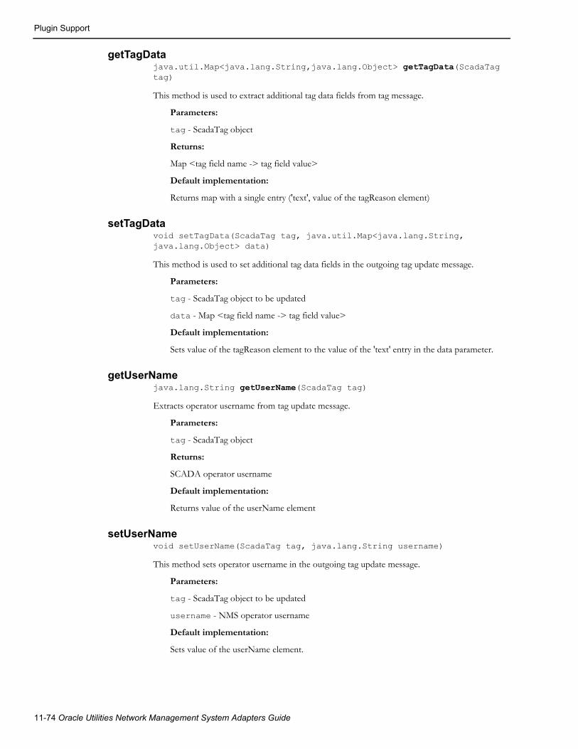
Plugin Support
getTagDatajava.util.Map<java.lang.String,java.lang.Object> getTagData(ScadaTag tag)
This method is used to extract additional tag data fields from tag message.
Parameters:
tag - ScadaTag object
Returns:
Map <tag field name -> tag field value>
Default implementation:
Returns map with a single entry ('text', value of the tagReason element)
setTagDatavoid setTagData(ScadaTag tag, java.util.Map<java.lang.String, java.lang.Object> data)
This method is used to set additional tag data fields in the outgoing tag update message.
Parameters:
tag - ScadaTag object to be updated
data - Map <tag field name -> tag field value>
Default implementation:
Sets value of the tagReason element to the value of the 'text' entry in the data parameter.
getUserNamejava.lang.String getUserName(ScadaTag tag)
Extracts operator username from tag update message.
Parameters:
tag - ScadaTag object
Returns:
SCADA operator username
Default implementation:
Returns value of the userName element
setUserNamevoid setUserName(ScadaTag tag, java.lang.String username)
This method sets operator username in the outgoing tag update message.
Parameters:
tag - ScadaTag object to be updated
username - NMS operator username
Default implementation:
Sets value of the userName element.
11-74 Oracle Utilities Network Management System Adapters Guide

Plugin Support
getActionAction getAction(ScadaTag tag)
This method is used to extract action from tag update message. Action determines if the request is to place a new tag, update an existing tag or remove an existing tag.
Parameters:
tag - ScadaTag object
Returns:
action
• NEW - add new tag
• CHANGE - update an existing tag
• DELETE - delete an existing tag
Default implementation:
Returns value of the verb attribute
setActionvoid setAction(ScadaTag tag, Action action)
This method is used during synchronization process to set action value in the tag update message, which is later extracted by the getAction method.
Parameters:
tag - ScadaTag object to be updated
action - action
• NEW - add new tag
• CHANGE - update an existing tag
• DELETE - delete an existing tag
Default implementation:
Sets value of the verb attribute
MultiSpeak Adapter 11-75

Plugin Support
buildScadaPointIdjava.lang.String buildScadaPointId(com.splwg.oms.common.intersys.Handle nmsDeviceHandle, java.lang.String nmsDeviceAlias, int phase) throws java.lang.IllegalArgumentException
This method is used to construct SCADA point id for status of an NMS device.
Note: This is the first of two overloaded versions of the buildScadaPointId method.
Parameters:
nmsDeviceHandle - NMS device handle
nmsDeviceAlias - NMS device alias
phase - phase
Returns:
SCADA point id or null if not supported
Throws:
java.lang.IllegalArgumentException - SCADA point id cannot be constructed for the given arguments
Default implementation:
Constructs SCADA point id of the following format:
• <base name>[#<phase text>]
• <base name> - nmsDeviceHandle if provided otherwise nmsDeviceAlias
• <phase code> - determined from the phase parameter according to the following rules: 1 - 'A', 2 - 'B', 4 - 'C', otherwise empty string
buildScadaPointIdjava.lang.String
buildScadaPointId(com.splwg.oms.common.intersys.HandlenmsDeviceHandlejava.lang.String nmsDeviceAlias, int phase, java.lang.String scadaPointId)throws java.lang.IllegalArgumentException
This method is used to construct SCADA point id for status of an NMS device.
Note: This is the second of two overloaded versions of the buildScadaPointId method.
Parameters:
nmsDeviceHandle - NMS device handle
nmsDeviceAlias - NMS device alias
phase - phase
scadaPointId - SCADA point ID for the device status (only available for SCADA devices).
Returns:
SCADA point id or null if not supported
Throws:
java.lang.IllegalArgumentException - SCADA point id cannot be constructed for
the given arguments
11-76 Oracle Utilities Network Management System Adapters Guide

Plugin Support
Default implementation:
Invokes the buildScadaPointId method. which does not accept the scadaPointId parameter. Thus the scadaPointId parameter passed to this method is not used in default implementation.
parseScadaPointIdParsedSCADAPointId parseScadaPointId(java.lang.String scadaPointId)throws java.lang.IllegalArgumentException
Parse SCADA point id.
Parameters:
scadaPointId - SCADA point id
Returns:
ParsedSCADAPountId object
Throws:
java.lang.IllegalArgumentException - if scadaPointId cannot be parsed
Default implementation:
Populates NMS device id in ParsedSCADAPointId with scadaPointId argument.
generateControlScadaControl generateControl(ExpectedAction action)
This method is used to create ScadaControl object based on information from the EXPECTED_ACTIONS table.
Parameters:
action - row from EXPECTED_ACTIONS table
Returns:
ScadaControl object or null is controls are not supported
Default implementation:
Returns null
isScadaPointboolean isScadaPoint(final MspObject obj)
This method is used to determine if obj is a SCADA-telemetered point. Currently this method gets invoked only for status points.
Parameters:
obj - MultiSpeak object
Returns:
true if obj is a SCADA-telemetered point, otherwise false
Default implementation:
Returns true
MultiSpeak Adapter 11-77
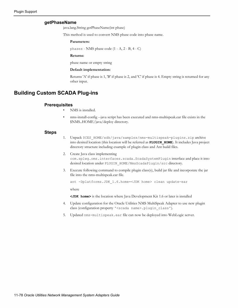
Plugin Support
getPhaseNamejava.lang.String getPhaseName(int phase)
This method is used to convert NMS phase code into phase name.
Parameters:
phases - NMS phase code (1 - A, 2 - B, 4 - C)
Returns:
phase name or empty string
Default implementation:
Returns 'A' if phase is 1, 'B' if phase is 2, and 'C' if phase is 4. Empty string is returned for any other input.
Building Custom SCADA Plug-ins
Prerequisites• NMS is installed.
• nms-install-config --java script has been executed and nms-multispeak.ear file exists in the $NMS_HOME/java/deploy directory.
Steps1. Unpack $CES_HOME/sdk/java/samples/nms-multispeak-plugins.zip archive
into desired location (this location will be referred as PLUGIN_HOME). It includes Java project directory structure including example of plugin class and Ant build files.
2. Create Java class implementing com.splwg.oms.interfaces.scada.ScadaSystemPlugin interface and place it into desired location under PLUGIN_HOME/NmsScadaPlugin/src directory.
3. Execute following command to compile plugin class(s), build jar file and incorporate the jar file into the nms-multispeak.ear file.
ant -Dplatforms.JDK_1.6.home=<JDK home> clean update-ear
where
<JDK home> is the location where Java Development Kit 1.6 or later is installed
4. Update configuration for the Oracle Utilities NMS MultiSpeak Adapter to use new plugin class (configuration property '<scada name>.plugin_class').
5. Updated nms-multispeak.ear file can now be deployed into WebLogic server.
11-78 Oracle Utilities Network Management System Adapters Guide

High-Level Messages
High-Level Messages
SCADASCADA component of the NMS MultiSpeak adapter responds to several high-level messages. High-level message can be sent using Action command-line utility.
Action -java multispeak.SCADA <message>
Following messages are supported:
RELOAD
Forces adapter to reload configuration for the SCADA component.
RESYNC [statuses|analogs|tags] [<scada id>|<scada name>]
Initiates synchronization sequence.
If 'statuses', 'analogs' or 'tags' qualifier is present in the message then synchronization sequence is executed only for that particular data flow. Otherwise full synchronization sequence is executed.
If <scada id> or <scada name> is specified then synchronization sequence is executed only for the designated SCADA system. Otherwise synchronization sequence is executed for all SCADA systems the adapter is connected to.
FOCUS <user> <device> [<display>] [<action>]
Causes HighlightObjectInDisplay message to be sent to the SCADA system(s). This message is used for display integration between NMS and SCADA system. For example, NMS operator can select a SCADA device in NMS viewer and trigger action, which would cause the same device to be selected/highlighted on SCADA system's display.
Parameters:
• <user> - username of SCADA operator
• <device> - NMS device handle
• <display> - SCADA display
• <action> - action to perform
MultiSpeak Adapter 11-79

High-Level Messages
AMRThe AMR component of the NMS MultiSpeak adapter responds to several high-level messages. High-level message can be sent using Action command-line utility.
Action -java multispeak.AMR <message>
The following messages are supported:
PING <meter id>Initiates “urgent” meter ping request for a single meter. <meter id> is the internal NMS meter identifier. When response to this ping request is received, the high-level message PING_RESPONSE is sent to the client, which initiated the ping.
PING_RESPONSE <meter id> <meter status> <raw meter status>
Response to the PING message. This is an outgoing message. It should not be sent to the adapter. The client, which sent the PING message, is expected to handle this message.
Parameters:
• <meter id> - the same meter identifier, which was sent in the PING message being responded to.
• <meter status> - meter status.
Possible values:
ON - meter has power
OFF - meter does not have power
UNKNOWN - undetermined meter status
ERROR - error occurred while trying to ping the meter
• <raw meter status> - raw meter status value as received from the AMR/AMI system.
11-80 Oracle Utilities Network Management System Adapters Guide

Troubleshooting
TroubleshootingNMS MultiSpeak Adapter uses Apache log4j library to log error, warning and debug messages. To enable debug output following lines should be added to the log4j configuration file used by the WebLogic Server where the Adapter is deployed.
<Logger name="com.splwg.oms.interfaces" level="debug" additivity="false"> <AppenderRef ref="Console"/></Logger><Logger name="com.splwg.oms.ws.multispeak" level="debug" additivity="false"> <AppenderRef ref="Console"/></Logger><Logger name="MultiSpeak" level="debug" additivity="false"> <AppenderRef ref="Console"/></Logger>
For additional details about configuring log4j logging in WebLogic Server see Configure Log4j Logging Services section in the Oracle Utilities Network Management System Installation Guide.
At runtime debug output can be toggled by sending high-level message to the appropriate component of the Adapter.
Action -java multispeak.<component> DEBUG
where <component> is one of
• AMR - AMR/AMI component
• AVL - AVL component
• SCADA - SCADA component
MultiSpeak Adapter 11-81

Troubleshooting
11-82 Oracle Utilities Network Management System Adapters Guide

Chapter 12Mobile Workforce Management Adapter
This chapter includes the following topics:
• Introduction
• Installation
• Database Schema
• Supported Data Flows
• Software Configuration
• High-Level Messages
• Troubleshooting
IntroductionThe Oracle Utilities Network Management System Mobile Workforce Management Adapter provides services required by the Oracle Utilities Network Management System Integration to Oracle Utilities Mobile Workforce Management.
One of the main functions of the adapter is translating Oracle Utilities Network Management System trouble events into Oracle Utilities Mobile Workforce Management activities. A trouble event is some situation in the electrical network, which requires attention (e.g., an outage causing some number of customers to be without electric power). An activity is a unit of work which a mobile crew needs to perform. Single event can be associated with multiple activities during its lifetime (for example, one crew may need to perform initial assessment before another crew or crews can start repair work). The responsibility of the adapter is to maintain relationships between the trouble events and activities and subsequently between trouble events and mobile crews.
Note: For more information see Oracle Utilities Network Management System Integration to Oracle Utilities Mobile Workforce Management Implementation Guide.
Mobile Workforce Management Adapter 12-1

Installation
InstallationThe Oracle Utilities Network Management System Mobile Workforce Management Adapter is delivered as a single file:
• $CES_HOME/dist/install/nms-mwm.ear.base – NMS-MWM adapter application.
The nms-install-config script is used to apply adapter configuration changes and create the nms-mwm.ear file, which can be deployed to the Oracle WebLogic Server (see Software Configuration on page 12-10 for configuration instructions).
To avoid performance impact on the main NMS application (cesejb.ear), it is recommended that the nms-mwm.ear not be deployed on the same managed server where the cesejb.ear is deployed; however, both managed servers need to be in the same Oracle WebLogic Server domain.
Adapter Installation Instructions for Oracle WebLogic ServerTopics
• Create a Managed Server (Optional)
• Create a Foreign JNDI Provider
Note: Creating a foreign JNDI provider is required when the nms-mwm.ear is on a different managed server than the cesejb.ear; if they are deployed on the same server, skip this step.
• Configure Foreign JNDI Provider
• Configure Data Source for the Adapters Managed Server
• Deploy the Adapter
Create a Managed Server (Optional)To simplify creation of a new managed server, you may clone an existing Oracle Utilities Network Management System managed server.
6. Log in to the WebLogic Server Administration Console.Note: The URL for WebLogic will be http://hostname:port/console where hostname represents the DNS name or IP address of the Administration Server, and port represents the number of the port on which the Administration Server is listening for requests (port 7001 by default).
7. Click Lock & Edit.
8. In the Domain Structure tree, expand Environment, then select Servers to open the Summary of Servers page.
9. Select an Oracle Utilities Network Management System server in the Servers table and click Clone.
10. Click the link to the cloned server and edit the settings:
• On the General tab, change the Listen Port and SSL Listen Port to unique values.
• On the Server Start tab, edit the Arguments field to remove the DRMI_URL parameter:-DRMI_URL=t3://<hostname:port>
12-2 Oracle Utilities Network Management System Adapters Guide

Installation
Create a Foreign JNDI ProviderIn order for the Oracle Utilities Network Management System Mobile Workforce Management Adapter, deployed on its own managed server, to communicate with the Oracle Utilities Network Management System (cesejb.ear), a foreign JNDI provider must be configured.
Note: Creating the foreign JNDI provider makes the cesejb.ear Enterprise JavaBeans (EJBs) appear local to the Oracle Utilities Network Management System Mobile Workforce Management Adapter.
1. Log in to the WebLogic Server Administration Console.
2. Click Lock & Edit.
3. In the Domain Structure tree, expand Services, then select Foreign JNDI Providers to open the Summary of Foreign JNDI Providers page.
4. On the Summary of Foreign JNDI Providers page, click New.
5. Enter a name for the new Foreign JNDI Provider.
6. Click Finish.
Configure Foreign JNDI Provider1. In the Foreign JNDI Provider table, click the new foreign JNDI provider name link.
2. In the Settings for Foreign_JNDI_Provider_Name General tab, enter the following information:Initial Context Factory: weblogic.jndi.WLInitialContextFactoryProvider URL: JNDI provider URL for the NMS (cesejb.ear)User: valid NMS user who has the ‘NmsService’ role in WebLogic ServerPassword: NMS user passwordConfirm Password: enter the same NMS user password to confirm
3. Click Save.
4. Select the Links tab.
5. Create the following foreign JNDI links:
6. Select the Targets tab.
7. Select the managed server where the Oracle Utilities Network Management System Mobile Workforce Management Adapter will be deployed and click Save.
If the Foreign JNDI Provider is configured to use SSL, and NMS is using a self-signed SSL certificate, then the following steps are needed to establish trust between the managed servers:
1. Log in to the WebLogic Server Administration Console.
2. Click Lock & Edit.
3. In the Domain Structure tree, expand Environment, and then select Servers to open the Summary of Servers page.
4. On the Summary of Servers page, click the server where the nms-mwm.ear will be deployed.
Link Name Local JNDI Name Remote JNDI Name
Session cesejb/Session/remote cesejb/Session/remote
PublisherBean cesejb/PublisherBean/remote cesejb/PublisherBean/remote
CrewOperations cesejb/CrewOperations/remote cesejb/CrewOperations/remote
Mobile Workforce Management Adapter 12-3
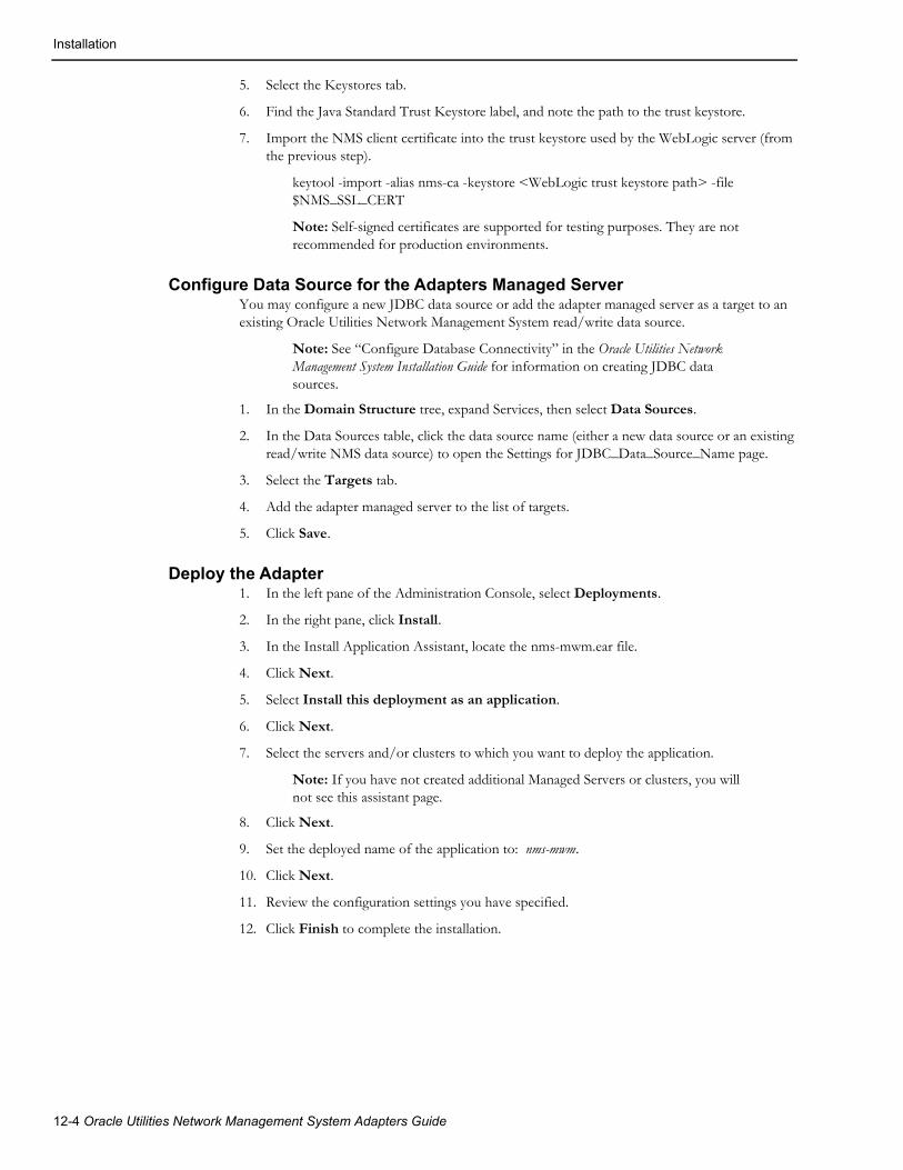
Installation
5. Select the Keystores tab.
6. Find the Java Standard Trust Keystore label, and note the path to the trust keystore.
7. Import the NMS client certificate into the trust keystore used by the WebLogic server (from the previous step).
keytool -import -alias nms-ca -keystore <WebLogic trust keystore path> -file $NMS_SSL_CERT
Note: Self-signed certificates are supported for testing purposes. They are not recommended for production environments.
Configure Data Source for the Adapters Managed ServerYou may configure a new JDBC data source or add the adapter managed server as a target to an existing Oracle Utilities Network Management System read/write data source.
Note: See “Configure Database Connectivity” in the Oracle Utilities Network Management System Installation Guide for information on creating JDBC data sources.
1. In the Domain Structure tree, expand Services, then select Data Sources.
2. In the Data Sources table, click the data source name (either a new data source or an existing read/write NMS data source) to open the Settings for JDBC_Data_Source_Name page.
3. Select the Targets tab.
4. Add the adapter managed server to the list of targets.
5. Click Save.
Deploy the Adapter1. In the left pane of the Administration Console, select Deployments.
2. In the right pane, click Install.
3. In the Install Application Assistant, locate the nms-mwm.ear file.
4. Click Next.
5. Select Install this deployment as an application.
6. Click Next.
7. Select the servers and/or clusters to which you want to deploy the application.
Note: If you have not created additional Managed Servers or clusters, you will not see this assistant page.
8. Click Next.
9. Set the deployed name of the application to: nms-mwm.
10. Click Next.
11. Review the configuration settings you have specified.
12. Click Finish to complete the installation.
12-4 Oracle Utilities Network Management System Adapters Guide

Database Schema
Database SchemaThe adapter uses several database tables where the information about trouble events, activities, and notifications is persisted.
OMS_MWM_EVENTSThis table stores the most recent information about the trouble events which have been sent to the Oracle Utilities Mobile Workforce Management system. This table is used to determine if trouble event update contains changes which should be sent out. This table is also used during synchronization sequence.
Field Description
EVENT_IDX Event index.Primary key.
EXTERNAL_ID Event’s external id.
DEVICE_CLS Class part of the event’s device handle.
DEVICE_IDX Index part of the event’s device handle.
PHASES Affected device phases.
STATUS Event’s condition status (PSO, PDO, etc.)
STATE_KEY Event’s state key.
NUM_CUST_OUT Number of affected customers.
NUM_CALLS Number of customer calls.
TROUBLE_CODE Event’s trouble code (combination of the unique trouble codes of the customer calls).
ERT Estimated restoration time.
COMMENTS Event comments.
LAST_UPDATE_TIME Last update time.
Mobile Workforce Management Adapter 12-5
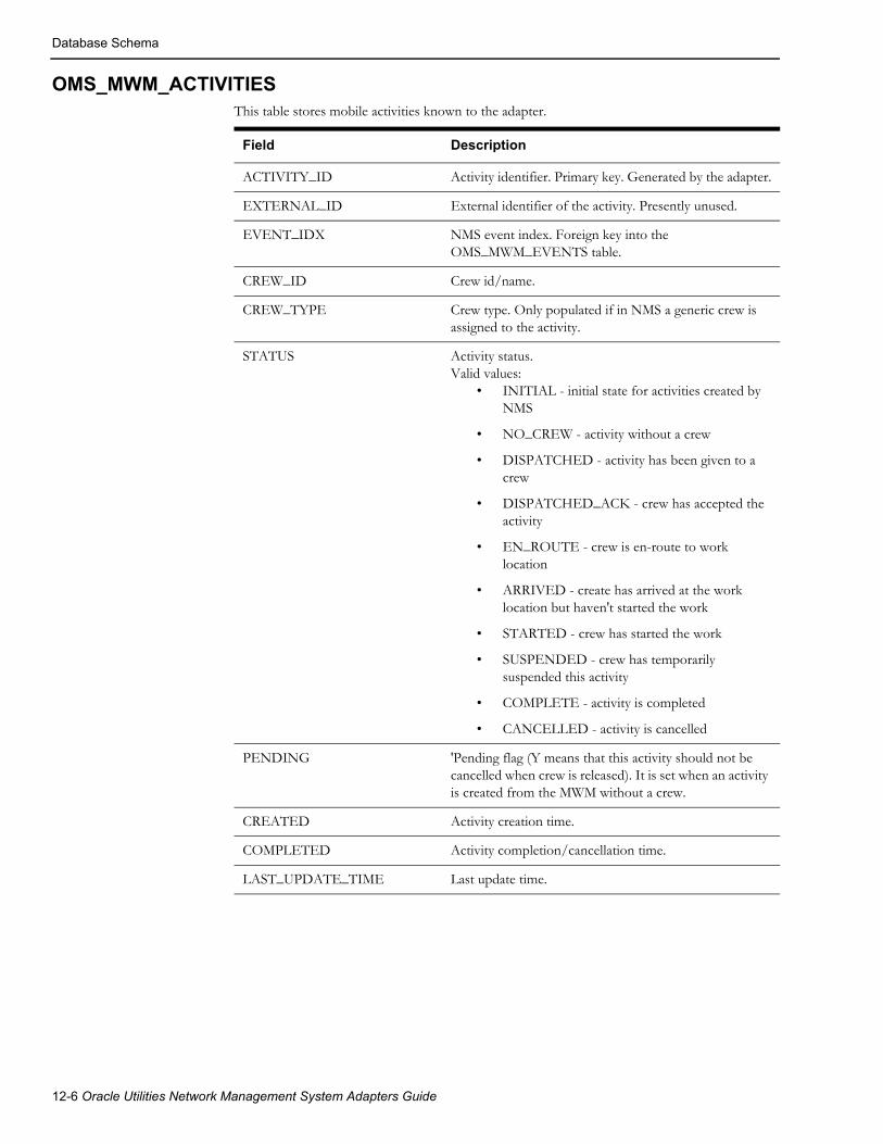
Database Schema
OMS_MWM_ACTIVITIESThis table stores mobile activities known to the adapter.
Field Description
ACTIVITY_ID Activity identifier. Primary key. Generated by the adapter.
EXTERNAL_ID External identifier of the activity. Presently unused.
EVENT_IDX NMS event index. Foreign key into the OMS_MWM_EVENTS table.
CREW_ID Crew id/name.
CREW_TYPE Crew type. Only populated if in NMS a generic crew is assigned to the activity.
STATUS Activity status.Valid values:
• INITIAL - initial state for activities created by NMS
• NO_CREW - activity without a crew
• DISPATCHED - activity has been given to a crew
• DISPATCHED_ACK - crew has accepted the activity
• EN_ROUTE - crew is en-route to work location
• ARRIVED - create has arrived at the work location but haven't started the work
• STARTED - crew has started the work
• SUSPENDED - crew has temporarily suspended this activity
• COMPLETE - activity is completed
• CANCELLED - activity is cancelled
PENDING 'Pending flag (Y means that this activity should not be cancelled when crew is released). It is set when an activity is created from the MWM without a crew.
CREATED Activity creation time.
COMPLETED Activity completion/cancellation time.
LAST_UPDATE_TIME Last update time.
12-6 Oracle Utilities Network Management System Adapters Guide
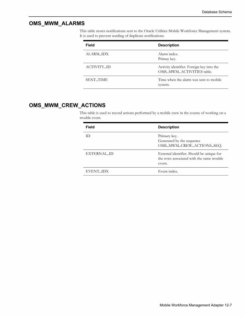
Database Schema
OMS_MWM_ALARMSThis table stores notifications sent to the Oracle Utilities Mobile Workforce Management system. It is used to prevent sending of duplicate notifications.
OMS_MWM_CREW_ACTIONSThis table is used to record actions performed by a mobile crew in the course of working on a trouble event.
Field Description
ALARM_IDX Alarm index. Primay key.
ACTIVITY_ID Activity identifier. Foreign key into the OMS_MWM_ACTIVITIES table.
SENT_TIME Time when the alarm was sent to mobile system.
Field Description
ID Primary key. Generated by the sequence OMS_MWM_CREW_ACTIONS_SEQ.
EXTERNAL_ID External identifier. Should be unique for the rows associated with the same trouble event.
EVENT_IDX Event index.
Mobile Workforce Management Adapter 12-7
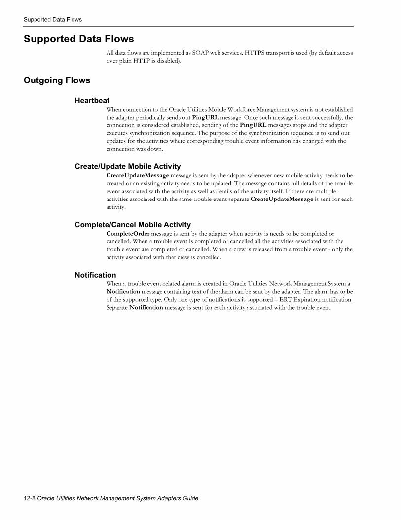
Supported Data Flows
Supported Data FlowsAll data flows are implemented as SOAP web services. HTTPS transport is used (by default access over plain HTTP is disabled).
Outgoing Flows
HeartbeatWhen connection to the Oracle Utilities Mobile Workforce Management system is not established the adapter periodically sends out PingURL message. Once such message is sent successfully, the connection is considered established, sending of the PingURL messages stops and the adapter executes synchronization sequence. The purpose of the synchronization sequence is to send out updates for the activities where corresponding trouble event information has changed with the connection was down.
Create/Update Mobile ActivityCreateUpdateMessage message is sent by the adapter whenever new mobile activity needs to be created or an existing activity needs to be updated. The message contains full details of the trouble event associated with the activity as well as details of the activity itself. If there are multiple activities associated with the same trouble event separate CreateUpdateMessage is sent for each activity.
Complete/Cancel Mobile ActivityCompleteOrder message is sent by the adapter when activity is needs to be completed or cancelled. When a trouble event is completed or cancelled all the activities associated with the trouble event are completed or cancelled. When a crew is released from a trouble event - only the activity associated with that crew is cancelled.
NotificationWhen a trouble event-related alarm is created in Oracle Utilities Network Management System a Notification message containing text of the alarm can be sent by the adapter. The alarm has to be of the supported type. Only one type of notifications is supported – ERT Expiration notification. Separate Notification message is sent for each activity associated with the trouble event.
12-8 Oracle Utilities Network Management System Adapters Guide

Supported Data Flows
Incoming Flows
Create Mobile ActivitySending CreateActivity message to the adapter creates a new mobile activity for an existing trouble event. Either an index of an existing trouble event or activity id of an existing activity needs to be passed in the request. Activity id of the newly created mobile activity is returned.
Update Mobile ActivitySending UpdateActivity message to the adapter allows to perform different crew-related actions depending on the state value passed in the request.
• Dispatched – assigns the mobile crew associated with the activity to the trouble event.
• EnRoute – places the mobile crew associated with the activity en-route to the trouble event.
• Started - places the mobile crew associated with the activity onsite for the trouble event.
• Suspended – suspends the mobile crew associated with the activity from working on the trouble event.
• NoCrew – releases the mobile crew associated with the activity from working on the trouble event. The same effect can be achieved by sending crewId in the message. Releasing the crew will cause the activity to be cancelled.
• Complete – completes the activity and releases the crew from the trouble event.
• Cancelled – cancels the activity and releases the crew from the trouble event.
Update Trouble EventSending UpdateEvent message to the adapter allows trouble event in the Oracle Utilities Network Management System to be updated. In particular it allows to
• Update Estimated Restoration Time
• Update Event Case Note
• Update Event Details information
• Update Failed Equipment information
• Update crew action steps
• Confirm Outage Device
• Move outage upstream or downstream
• Restore outage
• Cancel trouble event
QueryQuery request allows retrieving information from Oracle Utilities Network Management System. The following query types are supported:
• call – returns customer calls for specific trouble event
• customer – returns customer information for specific account number
• device_info – returns device information for specific device name (alias)
Mobile Workforce Management Adapter 12-9

Software Configuration
Asynchronous Message AcknowledgmentThe outgoing requests other than PingURL can be processed asynchronously. In such case the receiving side would send back response message containing error code ‘DEFERRED’. This is an indication the request is being processed asynchronously. The adapter would wait up to the configured amount of time (mwm.ack_wait_timeout) for the incoming MessageAck message containing result of the earlier request. There are 3 possible outcomes: Success – request was processed successfully; Error – an error occurred while processing the request; Failure – request cannot be delivered to the Oracle Utilities Mobile Workforce Management system. Failure response is treated as loss of connection between the system and initiates heartbeat flow followed by synchronization sequence. If MessageAck message is not received during the configured period of time then the Failure outcome is assumed.
Correspondence between the original request message and the MessageAck message is established through the messageId attribute in the message header of the original request. The MessageAck message must contain the same message id.
Software ConfigurationConfiguration for the Oracle Utilities Network Management System Mobile Workforce Management Adapter comes from the following sources:
• CES_PARAMETERS database table
• Oracle Utilities Network Management System configuration rules
• Data mapping configuration
Support for Encrypted Configuration ParametersSome configuration parameters that are stored in the CES_PARAMETERS database table contain sensitive information, such as authentication credentials, which should be protected. To protect this data, the VALUES column can be encrypted using Oracle WebLogic Server encrypt utility. This utility encrypts cleartext strings for use with Oracle WebLogic Server. Its output can then be used to populate values in CES_PARAMETERS database table.
Note: For detailed information see “encrypt” in the Oracle WebLogic Server Command Reference.
12-10 Oracle Utilities Network Management System Adapters Guide
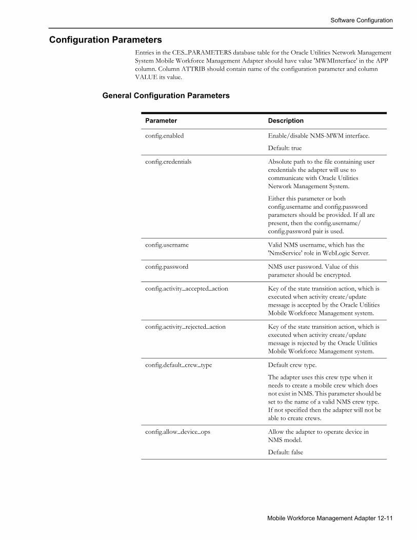
Software Configuration
Configuration ParametersEntries in the CES_PARAMETERS database table for the Oracle Utilities Network Management System Mobile Workforce Management Adapter should have value 'MWMInterface' in the APP column. Column ATTRIB should contain name of the configuration parameter and column VALUE its value.
General Configuration Parameters
Parameter Description
config.enabled Enable/disable NMS-MWM interface.
Default: true
config.credentials Absolute path to the file containing user credentials the adapter will use to communicate with Oracle Utilities Network Management System.
Either this parameter or both config.username and config.password parameters should be provided. If all are present, then the config.username/config.password pair is used.
config.username Valid NMS username, which has the 'NmsService' role in WebLogic Server.
config.password NMS user password. Value of this parameter should be encrypted.
config.activity_accepted_action Key of the state transition action, which is executed when activity create/update message is accepted by the Oracle Utilities Mobile Workforce Management system.
config.activity_rejected_action Key of the state transition action, which is executed when activity create/update message is rejected by the Oracle Utilities Mobile Workforce Management system.
config.default_crew_type Default crew type.
The adapter uses this crew type when it needs to create a mobile crew which does not exist in NMS. This parameter should be set to the name of a valid NMS crew type. If not specified then the adapter will not be able to create crews.
config.allow_device_ops Allow the adapter to operate device in NMS model.
Default: false
Mobile Workforce Management Adapter 12-11

Software Configuration
config.call_send_limit Maximum number of customer calls (incidents) to be included into an activity create/update message sent by the adapter. Customer calls with higher priority are included ahead of the calls with lower priority. Note: including large number of calls greatly increases message size.
Default: 0
config.suppress_ws_errors When enabled, it prevents errors from being included into web service response messages. Instead, the errors are just logged locally.
Default: false
mwm.activity_id_prefix Activity id prefix.
Default: NMS-
mwm.ws_request_timeout Timeout (in seconds) for the outgoing web service requests. Requests would fail if response is not received before the timeout expires.
Default: 30
mwm.ack_wait_timeout Timeout (in seconds) when waiting for acknowledgment of outgoing messages sent asynchronously. Link failure is declared if acknowledgment is not received before the timeout expires.
Default 60
mwm.url Default URL of the web service where the adapter should send outgoing messages.
mwm.url.<operation name> Operation-specific web service URLs. Allows for the outgoing messages to be send to the different URLs based on the message type (operation).
Valid operation names:
• PingURL - hearbeat message
• CreateUpdateOrder - creating or updating mobile activity
• CompleteOrder - completing or canceling mobile activity
• Notification - notification message
mwm.username Username included in the outgoing messages as part of HTTP Basic authentication.
Parameter Description
12-12 Oracle Utilities Network Management System Adapters Guide
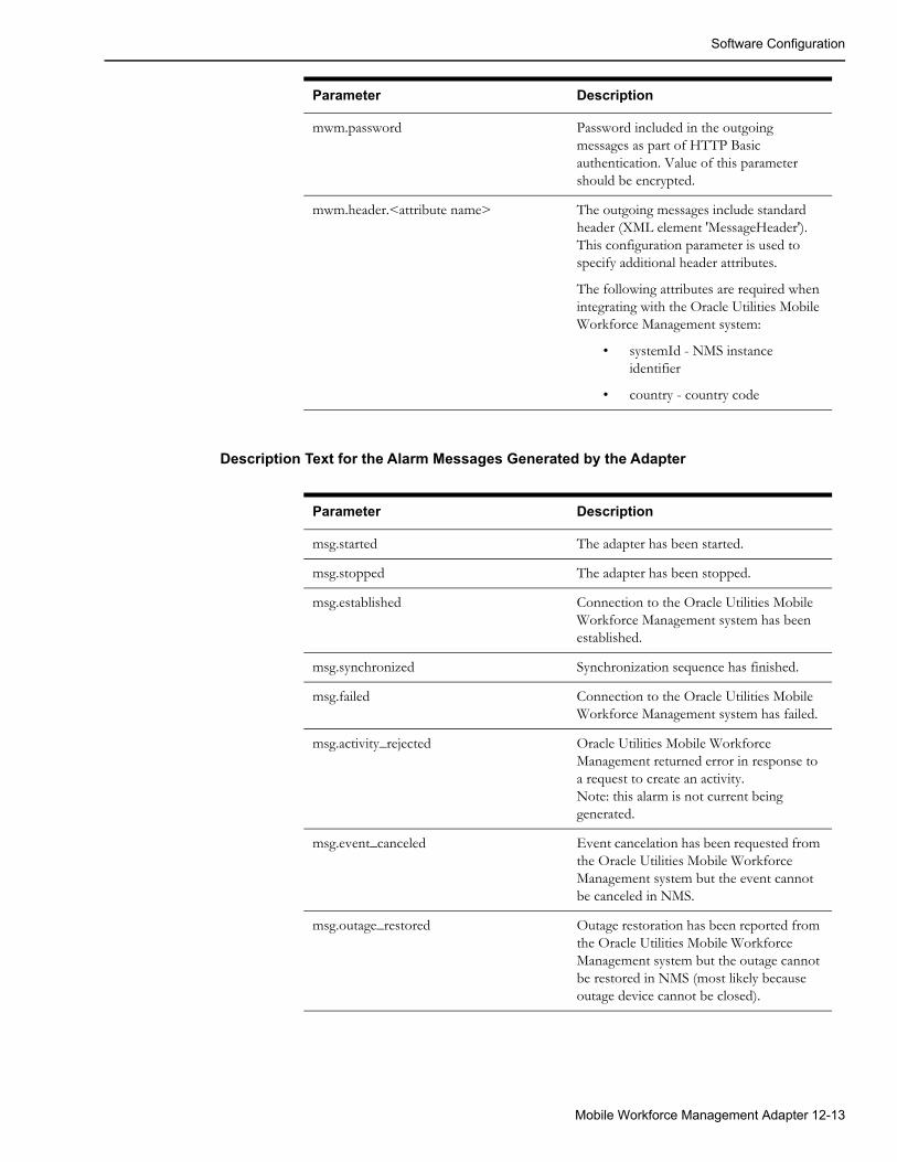
Software Configuration
Description Text for the Alarm Messages Generated by the Adapter
mwm.password Password included in the outgoing messages as part of HTTP Basic authentication. Value of this parameter should be encrypted.
mwm.header.<attribute name> The outgoing messages include standard header (XML element 'MessageHeader'). This configuration parameter is used to specify additional header attributes.
The following attributes are required when integrating with the Oracle Utilities Mobile Workforce Management system:
• systemId - NMS instance identifier
• country - country code
Parameter Description
Parameter Description
msg.started The adapter has been started.
msg.stopped The adapter has been stopped.
msg.established Connection to the Oracle Utilities Mobile Workforce Management system has been established.
msg.synchronized Synchronization sequence has finished.
msg.failed Connection to the Oracle Utilities Mobile Workforce Management system has failed.
msg.activity_rejected Oracle Utilities Mobile Workforce Management returned error in response to a request to create an activity.Note: this alarm is not current being generated.
msg.event_canceled Event cancelation has been requested from the Oracle Utilities Mobile Workforce Management system but the event cannot be canceled in NMS.
msg.outage_restored Outage restoration has been reported from the Oracle Utilities Mobile Workforce Management system but the outage cannot be restored in NMS (most likely because outage device cannot be closed).
Mobile Workforce Management Adapter 12-13

Software Configuration
Query Configuration
msg.outage_confirmed Outage has been confirmed by the Oracle Utilities Mobile Workforce Management system but the outage cannot be confirmed in NMS (outage device cannot be opened).
Parameter Description
Parameter Description
query.type.<query type> Query type.
Valid query types:
• device_info - device information
• customer - customer information
• call - customer call information for an event
query.<query type>.table Database table or view to query.
Not applicable to the "device_info" query type.
query.<query type>.where Additional conditions to be included in the query's WHERE clause.
query.<query type>.order_by Query's ORDER BY clause (sorting condition).
query.<query type>.max_results Maximum number of rows allowed to be returned for this query type.
Default: 100
query.<query type>.param.<param_name>
Maps query parameter name to a database column name.
The following parameters are defined for different query types:
• device_info
• deviceAlias - device alias
• customer
• accountNumber -customer account number
• call
• eventIdx - NMS event index
query.<query type>.column.<column_name>
Label for the data retrieved for the specified database column
12-14 Oracle Utilities Network Management System Adapters Guide

Software Configuration
Oracle Utilities Network Management System Configuration RulesOracle Utilities Network Management System configuration rules control various aspects of the system. You can configure these rules using the Oracle Utilities Network Management System Configuration Assistant tool. This section only covers the rules which directly affect the integration between Oracle Utilities Network Management System and Oracle Utilities Workforce Management system.
Rule Description
crewFollowOutageDevice This rule indicates whether or not crews dispatched to an event are automatically relocated if the device location changes. If this rule is enabled, dispatched crews are automatically relocated to the new device when an event moves to a different device in Oracle Utilities Network Management System. Typically, this rule should be enabled when Oracle Utilities Network Management System is integrated with Mobile Workforce Management system.
Default: no (disabled)
mobilePreassignCrew Allows Oracle Utilities Network Management System user to assign and release mobile crews.
Default: no (disabled)
Mobile Workforce Management Adapter 12-15

Software Configuration
repredictionCrewReassignment This rule enables or disables automatic crew reassignment/redispatch when event reprediction occurs in Oracle Utilities Network Management System.
For example:
Events A, B, and C exist on laterals off of a feeder backbone. Crew 1 is dispatched to event A, crew 2 is dispatched to event B, and crew 3 is assigned to event C. More calls come in on the feeder, eventually causing the system to repredict and group events A, B, and C to an upstream device. The resulting grouped event is called event A.
• If this rule is enabled, crew 1 remains dispatched to event A, crew 2 is undispatched from event B and redispatched to event A, and crew 3 is unassigned from event C and reassigned to event A.
• If this rule is disabled, crew 1 remains dispatched to event A, crew 2 is only undispatched from event B, and crew 3 is only unassigned from event C.
Default: yes (enabled)
sendToMobileState This rule specifies the state(s) at which an event is sent to Oracle Utilities Mobile Workforce Management. When an event transitions to one of the states defined in this rule, a "send to mobile" flag is set in the event. The Oracle Utilities Network Management System-Mobile Workforce Management Interface uses this flag to determine whether an event should be processed by the interface, triggering field order creation in Oracle Utilities Mobile Workforce Management.
Default: none
singleCrewPerEvent This rule indicates whether or not multiple crews can be assigned or dispatched to an event in Oracle Utilities Network Management System. If this rule is enabled, only one crew can be assigned or dispatched to an event at any given time. The repreditionCrewReassignment rule is implicitly disabled if this rule is enabled.
Default: no (disabled)
Rule Description
12-16 Oracle Utilities Network Management System Adapters Guide

Software Configuration
Data MappingData mapping converts data elements between a data source and a destination. Oracle Utilities Network Management System Mobile Workforce Management Adapter uses data mapping configuration to determine activity type and notification type for the outgoing messages.
Data Mapping OverviewThe Oracle Utilities Network Management System Mobile Workforce Management Adapter provides a configurable data-mapping facility. This facility can be used to populate certain data elements in the outgoing messages.
Many-to-many data mapping: Most data flows from Oracle Utilities Network Management System to Oracle Utilities Mobile Workforce Management use many-to-many data mapping. This means that a source value can be mapped to many different target values, based on one or more conditions.
Data mapping is rules-based. Rule configuration is defined in the following database tables:
useGenericAssign Allows treating of crews with crew key less 1000 as "generic crews".
Default: no (disabled)
useMdt This rule enables or disables MDT (Mobile Dispatch Terminal) crew flag functionality. This rule should be enabled when the Oracle Utilities Network Management System-Mobile Workforce Management Interface is being used.
Default: no (disabled)
Rule Description
Mapping Table Description
OMS_MWM_MAPPING_RULES This table defines the field to be mapped and, for many-to-many mapping, the value to be written to the mapped field if all conditions are met.
OMS_MWM_MAPPING_CHECKS This table defines conditions that may be applied to mapping rules.
OMS_MWM_MAPPING_RULE_CHECKS
This table associates a rule with a condition. Together, this table and the two previous tables are used to define many-to-many data mapping.
Mobile Workforce Management Adapter 12-17

Software Configuration
OMS_MWM_MAPPING_RULES TableThe OMS_MWM_MAPPING_RULES table contains rules for mapping data values between Oracle Utilities Network Management System and Oracle Utilities Mobile Workforce Management. The fields comprising each rule are described below:
Note: To define the default value for a field, configure a rule with no conditions and set that rule to be the last rule applied.
OMS_MWM_MAPPING_CHECKS TableThe OMS_MWM_MAPPING_CHECKS table contains conditions that can be used by the mapping rules defined in the OMS_MWM_MAPPING_RULES table.
Field Description
rule_id A unique identifier for this rule.
mapping The name of the mapping rule set used to group related mapping rules. For example, the mapping rule set 'mwmOrder' defines rules for mapping Oracle Utilities Network Management System event data to the corresponding field order data in Oracle Utilities Mobile Workforce Management for outgoing orders.
mapped_field The name of the field where the target value (the result of the mapping) should be written. For example, orderType, priority and alarmType are mapped fields.
mapped_value This is the value to be written to the mapped field if all conditions defined for this rule are met. This is also referred to as the target value.
table_id This field is not used.
rule_order The order in which this rule should be applied when a series of rules is being used. The lowest value is used first.
Field Description
check_id A unique identifier for this condition.
field_name The name of the field to which the condition applies.
cond_str The condition to be applied. For a description of the condition format, see the next section.
negate Indicates whether or not to negate the condition result. If this is set to Y, the result is negated. This field is optional.
12-18 Oracle Utilities Network Management System Adapters Guide

Software Configuration
Condition FormatThree different types of conditions are allowed in mapping rule checks. The format for each type of condition is shown in the table below.
Note: The angle brackets (<>) shown in the following table are not part of the format. The text inside the brackets should be replaced with the actual value as indicated.
OMS_MWM_MAPPING_RULE_CHECKS TableThis table is used to create many-to-many relationship between OMS_MWM_MAPPING_RULES and OMS_MWM_MAPPING_CHECKS tables. Each rule check associates a mapping rule with a condition (mapping check).
Mapping from Oracle Utilities Network Management System to Oracle Utilities Mobile Workforce Management
All data mapping rules for Oracle Utilities Network Management System to Oracle Utilities Mobile Workforce Management data flows belong to the “mwmOrder” rule set. This rule set supports mapping for the following data elements:
• Activity Type ( “orderType”)
• Activity Priority (“externalPriority”)
• Notification Type (“alarmType”)
These data elements are mapped using many-to-many data mapping, as described in the following example.
Condition Type Condition Format Description
Exact string compare <string to compare against> The condition is true if the field value (converted to a string) exactly matches the comparison string.
Regular expression @regex <regular expression> The condition is the true if the field value (converted to a string) matches the given regular expression.
Class inheritance @inheritFrom <class name> The condition is true if the field contains the class name specified in the condition or the name of any child class.
Field Description
rule_id The key to the mapping rule in the OMS_MWM_MAPPING_RULES table.
check_id The key to the condition in the table OMS_MWM_MAPPING_CHECK table.
Mobile Workforce Management Adapter 12-19
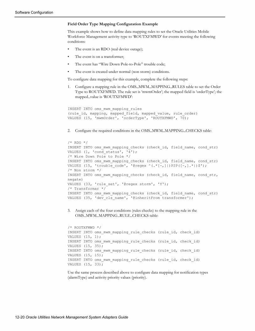
Software Configuration
Field Order Type Mapping Configuration Example
This example shows how to define data mapping rules to set the Oracle Utilities Mobile Workforce Management activity type to ‘ROUTXFMWD’ for events meeting the following conditions:
• The event is an RDO (real device outage);
• The event is on a transformer;
• The event has “Wire Down Pole-to-Pole” trouble code;
• The event is created under normal (non storm) conditions.
To configure data mapping for this example, complete the following steps:
1. Configure a mapping rule in the OMS_MWM_MAPPING_RULES table to set the Order Type to ROUTXFMWD. The rule set is ‘mwmOrder’; the mapped field is ‘orderType’; the mapped_value is ‘ROUTXFMWD':
INSERT INTO oms_mwm_mapping_rules(rule_id, mapping, mapped_field, mapped_value, rule_order)VALUES (15, 'mwmOrder', 'orderType', 'ROUTXFMWD', 70);
2. Configure the required conditions in the OMS_MWM_MAPPING_CHECKS table:
/* RDO */INSERT INTO oms_mwm_mapping_checks (check_id, field_name, cond_str)VALUES (1, 'cond_status', '4');/* Wire Down Pole to Pole */INSERT INTO oms_mwm_mapping_checks (check_id, field_name, cond_str)VALUES (15, 'trouble_code', '@regex ^(.*[-,]|)P2P([-,].*|)$');/* Non storm */INSERT INTO oms_mwm_mapping_checks (check_id, field_name, cond_str, negate)VALUES (33, 'rule_set', '@regex storm', 'Y');/* Transformar */INSERT INTO oms_mwm_mapping_checks (check_id, field_name, cond_str)VALUES (35, 'dev_cls_name', '@inheritFrom transformer');
3. Assign each of the four conditions (rules checks) to the mapping rule in the OMS_MWM_MAPPING_RULE_CHECKS table:
/* ROUTXFMWD */INSERT INTO oms_mwm_mapping_rule_checks (rule_id, check_id)VALUES (15, 1);INSERT INTO oms_mwm_mapping_rule_checks (rule_id, check_id)VALUES (15, 35);INSERT INTO oms_mwm_mapping_rule_checks (rule_id, check_id)VALUES (15, 15);INSERT INTO oms_mwm_mapping_rule_checks (rule_id, check_id)VALUES (15, 33);
Use the same process described above to configure data mapping for notification types (alarmType) and activity priority values (priority).
12-20 Oracle Utilities Network Management System Adapters Guide

Troubleshooting
High-Level MessagesThe Oracle Utilities Network Management System Mobile Workforce Management Adapter responds several commands sent as high-level messages.
High-level message can be sent using Action command-line utility.
Action any.publisher* ejb client NMS-MWM command <message>
Following messages are supported:
• RELOAD - Forces adapter to reload configuration and then initiates synchronization sequence.
• RESYNC - Initiates synchronization sequence.
• STOP - Temporarily stops the adapter.
• START - Re-starts previously stopped adapter.
TroubleshootingThe Oracle Utilities Network Management System Mobile Workforce Management Adapter uses Apache log4j library to log error, warning and debug messages. To enable debug output following lines should be added to the log4j configuration file used by the WebLogic Server where the adapter is deployed.
<Logger name="com.splwg.oms.interfaces.mwm" level="debug" additivity="false"> <AppenderRef ref="Console"/></Logger><Logger name="MOBILE" level="debug" additivity="false"> <AppenderRef ref="Console"/></Logger><Logger name="MOBLE_WS" level="debug" additivity="false"> <AppenderRef ref="Console"/></Logger><Logger name="MOBILE_WS" level="debug" additivity="false"> <AppenderRef ref="Console"/></Logger><Logger name="SOAP" level="debug" additivity="false"> <AppenderRef ref="Console"/></Logger>
For additional details about configuring log4j logging in WebLogic Server, see the Configure Log4j Logging Services section in the Oracle Utilities Network Management System Installation Guide.
Mobile Workforce Management Adapter 12-21

Troubleshooting
12-22 Oracle Utilities Network Management System Adapters Guide

Chapter 13SOAP Web Services
This chapter includes the following topics:
• Authentication
• Trouble Management Web Service
• Switching and Safety Web Service
• Damage Assessment Web Service
AuthenticationIn order to invoke Oracle Utilities Network Management System web services, the caller needs to be authenticated using valid Oracle Utilities Network Management System credentials. HTTP Basic Authentication protocol is used for authentication. Since HTTP Basic Authentication does not encrypt credentials, the HTTPS transport should be used.
SOAP Web Services 13-1

Trouble Management Web Service
Trouble Management Web ServiceTrouble Management web service provide access to the subset of the trouble management functionality available in the Oracle Utilities Network Management System.
Port TroubleServiceSOAPLocation: https://<nms host>:<nms port>/nms/trouble
Protocol: SOAP
Default Style: document
Transport Protocol: SOAP over HTTP
Target Namespace: http://oms.splwg.com/ws/trouble/
Operations
CreateEventCreates new event in NMS.
Operation Type: Request-response. The endpoint receives a message and sends a correlated message.
SOAP Action: http://oms.splwg.com/ws/trouble/CreateEvent
Input: CreateEventRequest (soap:body, use = literal)
parameters type CreateEvent
status type jobConditionStatus - type string with restriction - enum { 'NO_OUTAGE', 'PROBABLE_SERVICE_OUTAGE', 'PROBABLE_DEVICE_OUTAGE', 'REAL_SERVICE_OUTAGE', 'REAL_DEVICE_OUTAGE', 'RESERVED_5', 'RESERVED_6', 'NON_OUTAGE', 'CRITICAL_MEET', 'FUTURE_MEET', 'CONFIRMED_SERVICE_OUTAGE', 'CONFIRMED_SECONDARY_OUTAGE', 'ADDITIONAL_ALARM', 'PROBABLE_MOMENTARY_OUTAGE', 'REAL_MOMENTARY_OUTAGE', 'PLANNED_OUTAGE', 'NON_ELECTRIC_EVENT', 'SWITCHING_JOB', 'FAULT_CURRENT_EVENT', 'CVR_JOB' }
Condition status
device - optional; type handle
Device handle
deviceAlias - optional; type string
Device alias. If device handle is not provided device alias is used to determine it
phases - optional; type phaseCode
Affected device phases (default: all phases)
groupable - optional; type boolean
Groupable flag (default: non-groupable)
beginTime - optional; type dateTime
Event begin time (default: current time)
restoreTime - optional; type dateTime
Event restoration time (only applicable to momentary outages)
13-2 Oracle Utilities Network Management System Adapters Guide

Trouble Management Web Service
priority - optional; type int
Event priority
appliedRule - optional; type int
Initial applied rule value. When creating real momentary outage value 3 (SRS_SCADA) indicates that this is SCADA-reported event
accidental - optional; type int
0 - normal, 1 - accidental, 2 - planned
numMomentaries - optional; type int
Number of momentaries (only applicable to momentary outages)
description - optional; type string
Description text
dispatchGroup - optional; type string
Dispatch group
userCustOut - optional; type int
Number of customers affected by the created event. Populates USER_CUST_OUT field in the created event
ddsAlarm - optional; type handle
Handle of the DDS alarm (device operation) related to the event being created.
switchingPlan - optional; type handle
When creating SWITCHING_JOB event this element must be populated with the switching plan handle.
Output: CreateEventResponse (soap:body, use = literal)
parameters type CreateEventResponse
event type handle
Handle of the created event
Fault: TroubleServiceException (soap:fault, use = literal)
parameters type TroubleServiceFault
SOAP Web Services 13-3

Trouble Management Web Service
SetGenericFieldsUpdates generic fields of an existing event in NMS.
Operation Type: Request-response. The endpoint receives a message, and sends a correlated message.
SOAP Action: http://oms.splwg.com/ws/trouble/SetGenericFields
Input: SetGenericFieldsRequest (soap:body, use = literal)
parameters type SetGenericFields
• event - optional; type handle
Event handle
• externalId - optional; type string
Event's external id.
• fields type ArrayOfStringPair
Generic field values (list of name-value pairs).
Output: None.
Fault: TroubleServiceException (soap:fault, use = literal)
parameters type TroubleServiceFault
Faults
TroubleServiceFault• errors - unbounded; type Error
List of errors
• error type errorCode
Error code.
Valid values: 'ERROR', 'UNKNOWN_EVENT', 'UNKNOWN_GENERIC_FIELD', 'COMPLETED_EVENT'.
[a] errorMessage type string1
Error message
[a] eventIdx type int
Event index associated with the error
1. [a] bullets designate attributes.
13-4 Oracle Utilities Network Management System Adapters Guide
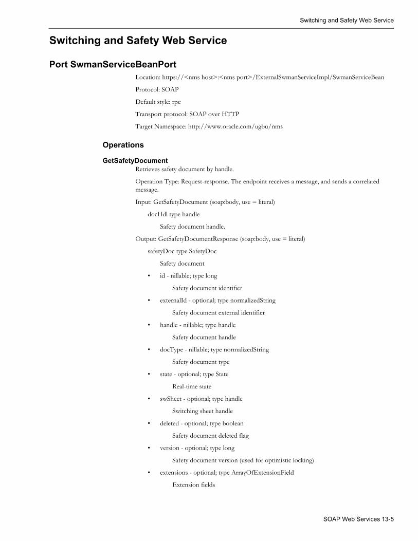
Switching and Safety Web Service
Switching and Safety Web Service
Port SwmanServiceBeanPort Location: https://<nms host>:<nms port>/ExternalSwmanServiceImpl/SwmanServiceBean
Protocol: SOAP
Default style: rpc
Transport protocol: SOAP over HTTP
Target Namespace: http://www.oracle.com/ugbu/nms
Operations
GetSafetyDocumentRetrieves safety document by handle.
Operation Type: Request-response. The endpoint receives a message, and sends a correlated message.
Input: GetSafetyDocument (soap:body, use = literal)
docHdl type handle
Safety document handle.
Output: GetSafetyDocumentResponse (soap:body, use = literal)
safetyDoc type SafetyDoc
Safety document
• id - nillable; type long
Safety document identifier
• externalId - optional; type normalizedString
Safety document external identifier
• handle - nillable; type handle
Safety document handle
• docType - nillable; type normalizedString
Safety document type
• state - optional; type State
Real-time state
• swSheet - optional; type handle
Switching sheet handle
• deleted - optional; type boolean
Safety document deleted flag
• version - optional; type long
Safety document version (used for optimistic locking)
• extensions - optional; type ArrayOfExtensionField
Extension fields
SOAP Web Services 13-5

Switching and Safety Web Service
• steps - optional; type ArrayOfSwStep
Switching steps associated with this safety document
• step - optional, unbounded; type SwStep
Switching step
• cls - nillable; type long
Switching step class
• id - nillable; type long
Switching step identifier
• parentId - optional; type long
Parent step
• groupNumber - optional; type long
Group number
• device - optional; type handle
Handle of the main device associated with this switching step
• deviceAlias - optional; type normalizedString
Alias of the main device associated with this switching step
• controlZone - optional; type ControlZone
Switching step control zone
• phases - optional; type phaseCode
Phases of the main device affected by this switching step
• availablePhases - optional; type phaseCode
All phases of the main device associated with this switching step
• secondaryDevice - optional; type handle
Handle of the secondary device associated with this switching step
• groundNode - optional; type handle
Grounding node associated with this switching step
• condition - optional; type handle
Condition associated with this switching step
• state - optional; type State
Switching step real-time state
13-6 Oracle Utilities Network Management System Adapters Guide
Switching and Safety Web Service
• controlAction - optional; type ControlAction
Control Tool action
• action - nillable; type normalizedString
• switchingCode - optional; type normalizedString
• attribute - optional; type long
[a] cls - required; type normalizedString
[a] idx - required; type normalizedString
[a] key - required; type long
Switching step control action
• revision - optional; type long
Switching step revision number
• description - optional; type string
Description
• comments - optional; type string
Comments
• plannedOffset - optional; type duration
Planned offset
• createTime - optional; type dateTime
Date/time when this step was created
• createUser - optional; type normalizedString
User who created this step
• updateTime - optional; type dateTime
Date/time when step was last updated
• updateUser - optional; type normalizedString
User who made the latest update this step
• instructTime - optional; type dateTime
Date/time when step was instructed
• instructUser - optional; type normalizedString
User who instructed this step
• executeTime - optional; type dateTime
Date/time when step was executed
• executeUser - optional; type normalizedString
User who executed this step
• executeOrder - optional; type long
Step execution order
• operationOutcome - optional; type normalizedString
Operation outcome
SOAP Web Services 13-7

Switching and Safety Web Service
• undoOperationOutcome - optional; type normalizedString
Undo operation outcome
• resultOfOperation - optional; type normalizedString
Result of operation
• resultFeeders - optional; type normalizedString
Result feeders
• lastResultOfOperation - optional; type normalizedString
Last result of operation
• editedOperation - optional; type normalizedString
Edited operation
• modelBuild - optional; type normalizedString
Step affected by model build
• safetyDocId - optional; type long
Safety document id (for safety-related steps)
• safetyDevStatus - optional; type normalizedString
Status of the device as it pertains to the associated safety document. This is used to keep track of a user's modifications to a safety document's device list. ADD - The device has been added as part of a viewer device selection. ADD_STEP - The device has been added as part of a switching sheet step association. COND_APPLIED - The condition has been applied and updated to the device in the device list. INCOMPLETE - The device is associated to a switching step where the condition has already been applied to the device. REMOVE - The device has been marked for removal and will be removed the next time the document transitions from the Unissued to Issued state. REMOVED - The device has been removed from the device list. These devices are filtered out of the device list.
• safetyCondAdded - optional; type long
Safety document version number where this safety condition step was added
• safetyCondRemoved - optional; type long
Safety document version number where this safety condition step was added
• crews - optional; type ArrayOfCrewId
Crew ids
• extensions - optional; type ArrayOfExtensionField
Extension fields
• crews - optional; type ArrayOfSafetyCrew
Crew information associated with this safety document
• crew - optional, unbounded; type SafetyCrew
Crew information associated with a safety document
• crewId - optional; type normalizedString
Crew id
13-8 Oracle Utilities Network Management System Adapters Guide

Switching and Safety Web Service
• position - optional; type normalizedString
Position the crew is in with regards to the zone of protection
• auditLog - optional; type ArrayOfAuditLogEntry
Audit log entries
• log - optional, unbounded; type AuditLogEntry
Audit log entry
• id - nillable; type long
Audit log entry identifier
• entryType - optional; type normalizedString
Audit log entry type
• userLog - optional; type string
User log
• device - optional; type handle
Device handle
• deviceAlias - optional; type normalizedString
Device alias
• state - optional; type State
State
• revision - optional; type long
Revision number
• comment - optional; type string
Log comment
• phases - optional; type phaseCode
Phases
• crews - optional; type ArrayOfCrewId
Crew ids
Fault: OmsServiceException (soap:fault, use = literal)
fault type OmsServiceException
GetSafetyDocumentsForSheetRetrieves all safety documents for a switching sheet.
Operation Type: Request-response. The endpoint receives a message, and sends a correlated message.
Input: GetSafetyDocumentsForSheet (soap:body, use = literal)
sheetHdl type handle
Switching sheet handle.
Output: GetSafetyDocumentsForSheetResponse (soap:body, use = literal)
safetyDocs type ArrayOfSafetyDoc
List of safety documents
SOAP Web Services 13-9

Switching and Safety Web Service
• safetyDoc - optional, unbounded; type SafetyDoc
Safety document (see GetSafetyDocument)
Fault: OmsServiceException (soap:fault, use = literal)
fault type OmsServiceException
GetSwitchingSheetRetrieves switching sheet by handle.
Operation Type: Request-response. The endpoint receives a message, and sends a correlated message.
Input: GetSwitchingSheet (soap:body, use = literal)
sheetHdl type handle
Switching sheet handle
Output: GetSwitchingSheetResponse (soap:body, use = literal)
swSheet type SwSheet
Switching sheet
• id - nillable; type long
Switching sheet identifier
• handle - nillable; type handle
Switching sheet handle
• externalId - optional; type normalizedString
Switching sheet external identifier
• device - optional; type handle
Handle of the main device associated with this switching sheet
• deviceAlias - optional; type normalizedString
Alias of the main device associated with this switching sheet
• controlZone - optional; type ControlZone
Switching sheet control zone
• owner - optional; type normalizedString
Switching sheet owner
• revision - optional; type long
Switching sheet revision number
• version - nillable; type long
Switching sheet version (used for optimistic locking)
• checkedIn - optional; type normalizedString
Switching sheet is checked in
• state - optional; type State
Real-time state
• createTime - optional; type dateTime
Date/time when this sheet was created
13-10 Oracle Utilities Network Management System Adapters Guide

Switching and Safety Web Service
• createUser - optional; type normalizedString
User who created this sheet
• updateTime - optional; type dateTime
Date/time when this sheet was last updated
• updateUser - optional; type normalizedString
User who updated this sheet last
• lockedTime - optional; type dateTime
Date/time when sheet was locked
• lockedUser - optional; type normalizedString
User who locked this sheet
• startTime - optional; type dateTime
Date/time when execution of this switching sheet is expected to start
• finishTime - optional; type dateTime
Date/time when execution of this switching sheet is expected to finish
• completedTime - optional; type dateTime
Completion date/time
• reworkDescription - optional; type string
Rework description
• reworkTime - optional; type dateTime
Rework date/time
• defaultOffset - optional; type duration
Default offset
• modelBuild - optional; type normalizedString
Switching sheet is affected by model build
• extensions - optional; type ArrayOfExtensionField
Extension fields
• steps - optional; type ArrayOfSwStep
Switching steps
• step - optional, unbounded; type SwStep
Switching step
• cls - nillable; type long
Switching step class
• id - nillable; type long
Switching step identifier
• parentId - optional; type long
Parent step
• groupNumber - optional; type long
Group number
SOAP Web Services 13-11

Switching and Safety Web Service
• device - optional; type handle
Handle of the main device associated with this switching step
• deviceAlias - optional; type normalizedString
Alias of the main device associated with this switching step
• controlZone - optional; type ControlZone
Switching step control zone
• phases - optional; type phaseCode
Phases of the main device affected by this switching step
• availablePhases - optional; type phaseCode
All phases of the main device associated with this switching step
• secondaryDevice - optional; type handle
Handle of the secondary device associated with this switching step
• groundNode - optional; type handle
Grounding node associated with this switching step
• condition - optional; type handle
Condition associated with this switching step
• state - optional; type State
Switching step real-time state
• controlAction - optional; type ControlAction
Control tool action
• action - nillable; type normalizedString
• switchingCode - optional; type normalizedString
• attribute - optional; type long
[a] cls - required; type normalizedString
[a] idx - required; type normalizedString
[a] key - required; type long
Switching step control action
• revision - optional; type long
Switching step revision number
• description - optional; type string
Description
• comments - optional; type string
Comments
• plannedOffset - optional; type duration
Planned offset
• createTime - optional; type dateTime
Date/time when this step was created
• createUser - optional; type normalizedString
13-12 Oracle Utilities Network Management System Adapters Guide

Switching and Safety Web Service
User who created this step
• updateTime - optional; type dateTime
Date/time when step was last updated
• updateUser - optional; type normalizedString
User who made the latest update this step
• instructTime - optional; type dateTime
Date/time when step was instructed
• instructUser - optional; type normalizedString
User who instructed this step
• executeTime - optional; type dateTime
Date/time when step was executed
• executeUser - optional; type normalizedString
User who executed this step
• executeOrder - optional; type long
Step execution order
• operationOutcome - optional; type normalizedString
Operation outcome
• undoOperationOutcome - optional; type normalizedString
Undo operation outcome
• resultOfOperation - optional; type normalizedString
Result of operation
• resultFeeders - optional; type normalizedString
Result feeders
• lastResultOfOperation - optional; type normalizedString
Last result of operation
• editedOperation - optional; type normalizedString
Edited operation
• modelBuild - optional; type normalizedString
Step affected by model build
• safetyDocId - optional; type long
Safety document id (for safety-related steps)
• safetyDevStatus - optional; type normalizedString
Status of the device as it pertains to the associated safety document. This is used to keep track of a user's modifications to a safety document's device list. ADD - The device has been added as part of a viewer device selection. ADD_STEP - The device has been added as part of a switching sheet step association. COND_APPLIED - The condition has been applied and updated to the device in the device list. INCOMPLETE - The device is associated to a switching step where the condition has already been applied to the device. REMOVE - The device has been marked for removal and will be removed the next time the document
SOAP Web Services 13-13

Switching and Safety Web Service
transitions from the Unissued to Issued state. REMOVED - The device has been removed from the device list. These devices are filtered out of the device list.
• safetyCondAdded - optional; type long
Safety document version number where this safety condition step was added
• safetyCondRemoved - optional; type long
Safety document version number where this safety condition step was added
• crews - optional; type ArrayOfCrewId
Crew ids
• extensions - optional; type ArrayOfExtensionField
Extension fields
• auditLog - optional; type ArrayOfAuditLogEntry
Audit log entries
• log - optional, unbounded; type AuditLogEntry
Audit log entry
• id - nillable; type long
Audit log entry identifier
• entryType - optional; type normalizedString
Audit log entry type
• userLog - optional; type string
User log
• device - optional; type handle
Device handle
• deviceAlias - optional; type normalizedString
Device alias
• state - optional; type State
State
• revision - optional; type long
Revision number
• comment - optional; type string
Log comment
• phases - optional; type phaseCode
Phases
• crews - optional; type ArrayOfCrewId
Crew ids
• standaloneSafetyDoc - optional; type SafetyDoc
Safety document (see GetSafetyDocument)
Fault: OmsServiceException (soap:fault, use = literal)
fault type OmsServiceException
13-14 Oracle Utilities Network Management System Adapters Guide
Switching and Safety Web Service
createSwmanSheetFromExternalSystemCreates new or updates an existing switching sheet.
Operation Type: Request-response. The endpoint receives a message, and sends a correlated message.
Input: createSwmanSheetFromExternalSystem (soap:body, use = literal)
dataString type string
XML representation of the switching sheet.
sheetHdl type handle
Switching sheet handle.
Output: createSwmanSheetFromExternalSystemResponse (soap:body, use = literal)
return type int
Return code.
sheetHdl type handle
Switching sheet handle.
Fault: OmsServiceException (soap:fault, use = literal)
fault type OmsServiceException
sheetStateTransitionExecutes state transition on a switching sheet.
Operation Type: Request-response. The endpoint receives a message, and sends a correlated message.
Input: sheetStateTransition (soap:body, use = literal)
sheetHdl type handle
Switching sheet handle.
actionType type string
State transition action type.
actionName type string
State transition action name.
username type string
Username.
Output: sheetStateTransitionResponse (soap:body, use = literal)
Fault: OmsServiceException (soap:fault, use = literal)
fault type OmsServiceException
SOAP Web Services 13-15

Damage Assessment Web Service
Damage Assessment Web ServiceOracle Utilities Network Management System Damage Assessment web service
Port DamageServiceSOAP Location: https://<nms host>:<nms port>/nms/damage
Protocol: SOAP
Default style: document
Transport protocol: SOAP over HTTP
Target Namespace: http://oms.splwg.com/ws/damage/
Operations
CompleteDamageReportCompletes an existing damage report.
Operation Type: Request-response. The endpoint receives a message, and sends a correlated message.
SOAP Action: http://oms.splwg.com/ws/damage/CompleteDamageReport
Input: CompleteDamageReportRequest (soap:body, use = literal)
parameters type CompleteDamageReport
reportId type long
Damage report id
Output: CompleteDamageReportResponse (soap:body, use = literal)
parameters type CompleteDamageReportResponse
report type damageReport
Damage assessment report
• id - optional; type long
Damage report unique identifier assigned by the server
• groupable - optional; type boolean
Allow this damage report to be grouped upstream
• externalId - optional; type string
External id of the damage assessment incident in NMS
• eventIdx - optional; type int
Index of the event associated with this damage report
• eventExternalId - optional; type string
External id of the event associated with this damage report
• patrolEventIdx - optional; type int
Index of the patrol event associated with this damage report
• device - optional; type handle
[a] cls - required; type short
[a] index - required; type int
13-16 Oracle Utilities Network Management System Adapters Guide

Damage Assessment Web Service
[a] app - optional; type short
Handle of the affected device
• deviceAlias - optional; type string
Alias of the affected device
• feeder - optional; type string
Feeder name
• gpsLocation - optional; type gpsLocation
GPS location
• latitude type double
Latitude
• longitude type double
Longitude
GPS location of the damage
• zone - optional; type string
• grid - optional; type string
• location - optional; type string
• section - optional; type string
• city - optional; type string
• address - optional; type string
Street address of the damage
• phases - optional; type phaseCode - type string with restriction - enum { 'NONE', 'A', 'B', 'AB', 'C', 'AC', 'BC', 'ABC', 'N', 'AN', 'BN', 'ABN', 'CN', 'ACN', 'BCN', 'ABCN', 'Unknown' }
Affected phases
• loadAffected - optional; type boolean
Is damage causing an outage
• roadBlocked - optional; type boolean
Is road blocked
• streetLightDamage - optional; type boolean
Is street light damage reported
• hazardous - optional; type boolean
Is damage hazardous
• crew - optional; type crew
[a] id - required; type string
NMS crew identifier (crew name)
[a] mobileNumber - optional; type string
Crew's mobile (radio) number
Crew, who submitted this damage report
• stateName - optional; type string
SOAP Web Services 13-17

Damage Assessment Web Service
Damage report state (New, Assessed, etc.)
• stateBitmask - optional; type int
Damage report state bitmask (New=0x1, Assessed=0x2, Complete=0x4, Obsolete=0x8)
• active - optional; type boolean
• reportTime - optional; type dateTime
• lastModified - optional; type dateTime
• version - optional; type long
Damage report version used for optimistic concurrency control
• damageType - optional, unbounded; type reportDamageType
• typeId type int
• typeName - optional; type normalizedString
• accessible - optional; type int
• inaccessible - optional; type int
List of specific damage instances
• damageComment - optional; type string
• requiredPart - optional, unbounded; type reportDamagePart
• quantity - optional; type int
• partId type string
List of required parts/materials needed to address reported damage
• requirePartsComment type string
• crewType - optional, unbounded; type crewType
• id type int
Crew type id
• name type string
Crew type name
List of crew types needed to address reported damage
• miscField1 - optional; type string
Mapped to database column DAMAGE_REPORT.MISC_TEXT1
• miscField2 - optional; type string
Mapped to database column DAMAGE_REPORT.MISC_TEXT2
• miscField3 - optional; type string
Mapped to database column DAMAGE_REPORT.MISC_TEXT3
• miscField4 - optional; type string
Mapped to database column DAMAGE_REPORT.MISC_TEXT4
• miscField5 - optional; type string
Mapped to database column DAMAGE_REPORT.MISC_TEXT5
13-18 Oracle Utilities Network Management System Adapters Guide
Damage Assessment Web Service
• miscField6 - optional; type string
Mapped to database column DAMAGE_REPORT.MISC_OPTION1
• miscField7 - optional; type string
Mapped to database column DAMAGE_REPORT.MISC_OPTION2
• miscField8 - optional; type string
Mapped to database column DAMAGE_REPORT.MISC_OPTION3
• miscField9 - optional; type string
Mapped to database column DAMAGE_REPORT.MISC_OPTION4
• miscField10 - optional; type string
Mapped to database column DAMAGE_REPORT.MISC_OPTION5
• udf1 - optional; type string
User-defined field 1
• udf2 - optional; type string
User-defined field 2
• udf3 - optional; type string
User-defined field 3
• udf4 - optional; type string
User-defined field 4
• udf5 - optional; type string
User-defined field 5
• udf6 - optional; type string
User-defined field 6
• udf7 - optional; type string
User-defined field 7
• udf8 - optional; type string
User-defined field 8
• udf9 - optional; type string
User-defined field 9
• udf10 - optional; type string
User-defined field 10
• udf11 - optional; type string
User-defined field 11
• udf12 - optional; type string
User-defined field 12
• udf13 - optional; type string
User-defined field 13
• udf14 - optional; type string
User-defined field 14
SOAP Web Services 13-19

Damage Assessment Web Service
• udf15 - optional; type string
User-defined field 15
• udf16 - optional; type string
User-defined field 16
• udf17 - optional; type string
User-defined field 17
• udf18 - optional; type string
User-defined field 18
• udf19 - optional; type string
User-defined field 19
• udf20 - optional; type string
User-defined field 20
• attachment - optional, unbounded; type attachment
List of damage report attachments. Actual attachment data is not included.
• data - optional; type base64Binary
Attachment data
• description - optional; type string
Description of the attachment
[a] id - required; type string
Attachment id (file name)
[a] reportId - required; type long
Damage report id
[a] uri - optional; type anyURI
Link to the attachment. Can be used instead of passing attachment data in the message
[a] contentType - optional; type string
MIME content type
[a] lastModified - optional; type dateTime
Last modification timestamp
Fault: DamageServiceException (soap:fault, use = literal)
parameters type DamageServiceFault
errors - unbounded; type Error
Damage Service error
• error type errorCode - type string with restriction - enum { 'CreateFailed', 'CompletedEvent', 'UnknownEvent', 'BadEventType', 'LoadAffectedSetForNonOutage', 'DatabaseError', 'UnknownReportId', 'AlreadyCompleted', 'StaleData', 'IncidentCreateFailed', 'InvalidCrewType', 'InvalidDamageType', 'InvalidRequiredPart', 'NeedEventOrDevice', 'NeedAddress', 'NeedCrewId', 'MoveFailed', 'AttachmentTooBig', 'AttachmentSaveError', 'AttachmentNotFound', 'Other' }
13-20 Oracle Utilities Network Management System Adapters Guide
Damage Assessment Web Service
String representation of the error code
[a] code type int
Error code
[a] reportId type long
Damage report id associated with the error
DeleteAttachmentsDeletes one or more damage report attachments.
Operation Type: Request-response. The endpoint receives a message, and sends a correlated message.
SOAP Action: http://oms.splwg.com/ws/damage/DeleteAttachments
Input: DeleteAttachmentsRequest (soap:body, use = literal)
parameters type DeleteAttachments
attachmentId - unbounded; type attachmentId
Identifier for damage report attachment
• id type string
Attachment id (file name). If empty then all attachments for this damage report are included.
• reportId type long
Damage report id
Output: DeleteAttachmentsResponse (soap:body, use = literal)
Fault: DamageServiceException (soap:fault, use = literal)
parameters type DamageServiceFault
errors - unbounded; type Error
Damage Service error
• error type errorCode - type string with restriction - enum { 'CreateFailed', 'CompletedEvent', 'UnknownEvent', 'BadEventType', 'LoadAffectedSetForNonOutage', 'DatabaseError', 'UnknownReportId', 'AlreadyCompleted', 'StaleData', 'IncidentCreateFailed', 'InvalidCrewType', 'InvalidDamageType', 'InvalidRequiredPart', 'NeedEventOrDevice', 'NeedAddress', 'NeedCrewId', 'MoveFailed', 'AttachmentTooBig', 'AttachmentSaveError', 'AttachmentNotFound', 'Other' }
String representation of the error code
[a] code type int
Error code
[a] reportId type long
Damage report id associated with the error
SOAP Web Services 13-21

Damage Assessment Web Service
GetAttachmentsRetrieves damage report attachments.
Operation Type: Request-response. The endpoint receives a message, and sends a correlated message.
SOAP Action: http://oms.splwg.com/ws/damage/GetAttachments
Input: GetAttachmentsRequest (soap:body, use = literal)
parameters type GetAttachments
attachmentId - unbounded; type attachmentId
Identifier for damage report attachment
• id type string
Attachment id (file name). If empty then all attachments for this damage report are included.
• reportId type long
Damage report id
Output: GetAttachmentsResponse (soap:body, use = literal)
parameters type GetAttachmentsResponse
result - optional, unbounded; type attachment
[a] data - optional; type base64Binary
Attachment data
[a] description - optional; type string
Description of the attachment
• id - required; type string
Attachment id (file name)
• reportId - required; type long
Damage report id
• uri - optional; type anyURI
Link to the attachment. Can be used instead of passing attachment data in the message
• contentType - optional; type string
MIME content type
• lastModified - optional; type dateTime
Last modification timestamp
Fault: DamageServiceException (soap:fault, use = literal)
parameters type DamageServiceFault
errors - unbounded; type Error
Damage Service error
• error type errorCode - type string with restriction - enum { 'CreateFailed', 'CompletedEvent', 'UnknownEvent', 'BadEventType', 'LoadAffectedSetForNonOutage', 'DatabaseError', 'UnknownReportId', 'AlreadyCompleted', 'StaleData', 'IncidentCreateFailed', 'InvalidCrewType', 'InvalidDamageType', 'InvalidRequiredPart', 'NeedEventOrDevice', 'NeedAddress',
13-22 Oracle Utilities Network Management System Adapters Guide

Damage Assessment Web Service
'NeedCrewId', 'MoveFailed', 'AttachmentTooBig', 'AttachmentSaveError', 'AttachmentNotFound', 'Other' }
String representation of the error code
• code type int
Error code
• reportId type long
Damage report id associated with the error
GetCrewTypesReturns all crew types configured in NMS.
Operation Type: Request-response. The endpoint receives a message, and sends a correlated message.
SOAP Action: http://oms.splwg.com/ws/damage/GetCrewTypes
Input: GetCrewTypesRequest (soap:body, use = literal)
parameters type GetCrewTypes
Output: GetCrewTypesResponse (soap:body, use = literal)
parameters type GetCrewTypesResponse
result - optional, unbounded; type crewType
• id type int
Crew type id
• name type string
Crew type name
Fault: DamageServiceException (soap:fault, use = literal)
parameters type DamageServiceFault
errors - unbounded; type Error
Damage Service error
[a] error type errorCode - type string with restriction - enum { 'CreateFailed', 'CompletedEvent', 'UnknownEvent', 'BadEventType', 'LoadAffectedSetForNonOutage', 'DatabaseError', 'UnknownReportId', 'AlreadyCompleted', 'StaleData', 'IncidentCreateFailed', 'InvalidCrewType', 'InvalidDamageType', 'InvalidRequiredPart', 'NeedEventOrDevice', 'NeedAddress', 'NeedCrewId', 'MoveFailed', 'AttachmentTooBig', 'AttachmentSaveError', 'AttachmentNotFound', 'Other' }
String representation of the error code
• code type int
Error code
• reportId type long
Damage report id associated with the error
SOAP Web Services 13-23
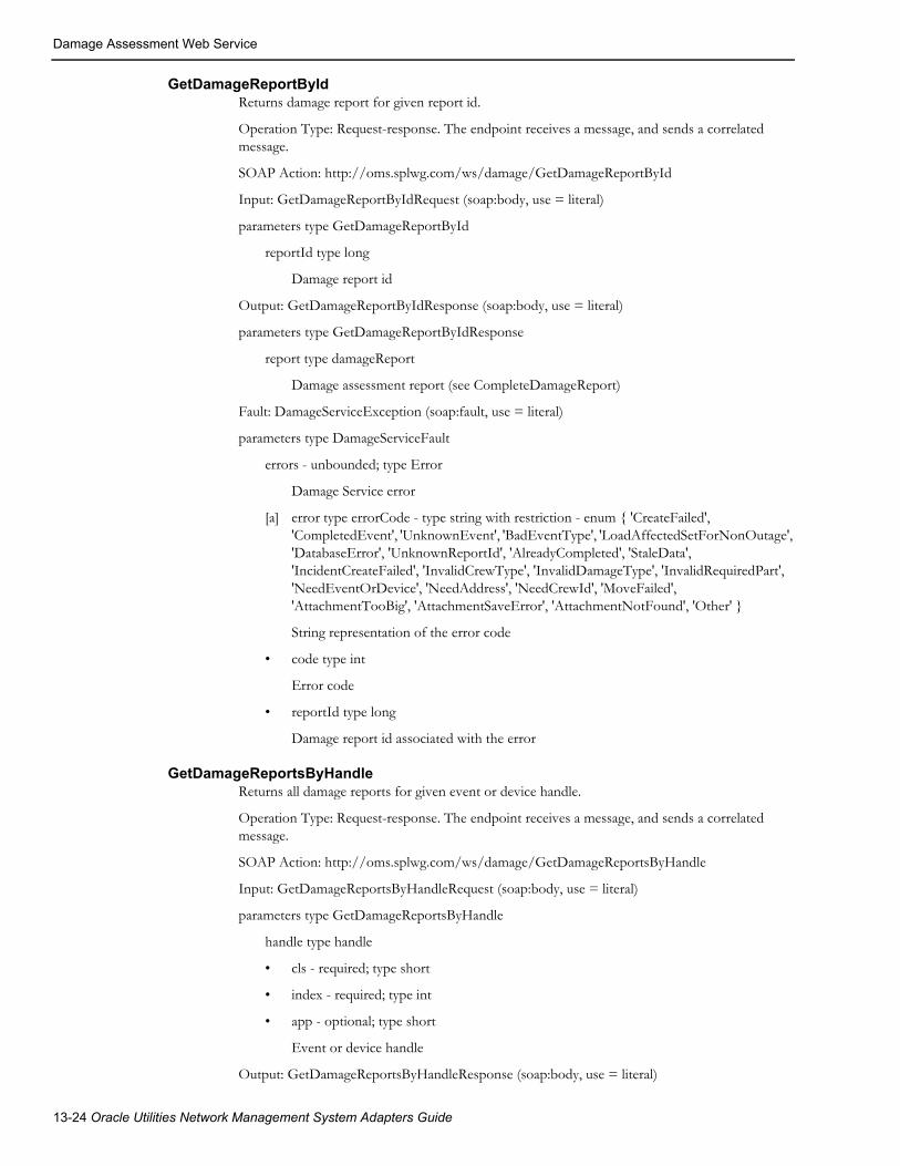
Damage Assessment Web Service
GetDamageReportByIdReturns damage report for given report id.
Operation Type: Request-response. The endpoint receives a message, and sends a correlated message.
SOAP Action: http://oms.splwg.com/ws/damage/GetDamageReportById
Input: GetDamageReportByIdRequest (soap:body, use = literal)
parameters type GetDamageReportById
reportId type long
Damage report id
Output: GetDamageReportByIdResponse (soap:body, use = literal)
parameters type GetDamageReportByIdResponse
report type damageReport
Damage assessment report (see CompleteDamageReport)
Fault: DamageServiceException (soap:fault, use = literal)
parameters type DamageServiceFault
errors - unbounded; type Error
Damage Service error
[a] error type errorCode - type string with restriction - enum { 'CreateFailed', 'CompletedEvent', 'UnknownEvent', 'BadEventType', 'LoadAffectedSetForNonOutage', 'DatabaseError', 'UnknownReportId', 'AlreadyCompleted', 'StaleData', 'IncidentCreateFailed', 'InvalidCrewType', 'InvalidDamageType', 'InvalidRequiredPart', 'NeedEventOrDevice', 'NeedAddress', 'NeedCrewId', 'MoveFailed', 'AttachmentTooBig', 'AttachmentSaveError', 'AttachmentNotFound', 'Other' }
String representation of the error code
• code type int
Error code
• reportId type long
Damage report id associated with the error
GetDamageReportsByHandleReturns all damage reports for given event or device handle.
Operation Type: Request-response. The endpoint receives a message, and sends a correlated message.
SOAP Action: http://oms.splwg.com/ws/damage/GetDamageReportsByHandle
Input: GetDamageReportsByHandleRequest (soap:body, use = literal)
parameters type GetDamageReportsByHandle
handle type handle
• cls - required; type short
• index - required; type int
• app - optional; type short
Event or device handle
Output: GetDamageReportsByHandleResponse (soap:body, use = literal)
13-24 Oracle Utilities Network Management System Adapters Guide

Damage Assessment Web Service
parameters type GetDamageReportsByHandleResponse
report - optional, unbounded; type damageReport
Damage assessment report (see CompleteDamageReport)
Fault: DamageServiceException (soap:fault, use = literal)
parameters type DamageServiceFault
errors - unbounded; type Error
Damage Service error
[a] error type errorCode - type string with restriction - enum { 'CreateFailed', 'CompletedEvent', 'UnknownEvent', 'BadEventType', 'LoadAffectedSetForNonOutage', 'DatabaseError', 'UnknownReportId', 'AlreadyCompleted', 'StaleData', 'IncidentCreateFailed', 'InvalidCrewType', 'InvalidDamageType', 'InvalidRequiredPart', 'NeedEventOrDevice', 'NeedAddress', 'NeedCrewId', 'MoveFailed', 'AttachmentTooBig', 'AttachmentSaveError', 'AttachmentNotFound', 'Other' }
String representation of the error code
• code type int
Error code
• reportId type long
Damage report id associated with the error
GetDamageReportsByPatrolReturns all damage reports for given patrol event index.
Operation Type: Request-response. The endpoint receives a message, and sends a correlated message.
SOAP Action: http://oms.splwg.com/ws/damage/GetDamageReportsByPatrol
Input: GetDamageReportsByPatrolRequest (soap:body, use = literal)
parameters type GetDamageReportsByPatrol
patrolEventIdx type int
Patrol event index
Output: GetDamageReportsByPatrolResponse (soap:body, use = literal)
parameters type GetDamageReportsByPatrolResponse
report - optional, unbounded; type damageReport
Damage assessment report (see CompleteDamageReport)
Fault: DamageServiceException (soap:fault, use = literal)
parameters type DamageServiceFault
errors - unbounded; type Error
Damage Service error
[a] error type errorCode - type string with restriction - enum { 'CreateFailed', 'CompletedEvent', 'UnknownEvent', 'BadEventType', 'LoadAffectedSetForNonOutage', 'DatabaseError', 'UnknownReportId', 'AlreadyCompleted', 'StaleData', 'IncidentCreateFailed', 'InvalidCrewType', 'InvalidDamageType', 'InvalidRequiredPart', 'NeedEventOrDevice', 'NeedAddress', 'NeedCrewId', 'MoveFailed', 'AttachmentTooBig', 'AttachmentSaveError', 'AttachmentNotFound', 'Other' }
String representation of the error code
SOAP Web Services 13-25
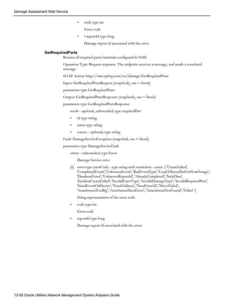
Damage Assessment Web Service
• code type int
Error code
• • reportId type long
Damage report id associated with the error
GetRequiredPartsReturns all required parts/materials configured in NMS.
Operation Type: Request-response. The endpoint receives a message, and sends a correlated message.
SOAP Action: http://oms.splwg.com/ws/damage/GetRequiredParts
Input: GetRequiredPartsRequest (soap:body, use = literal)
parameters type GetRequiredParts
Output: GetRequiredPartsResponse (soap:body, use = literal)
parameters type GetRequiredPartsResponse
result - optional, unbounded; type requiredPart
• id type string
• name type string
• source - optional; type string
Fault: DamageServiceException (soap:fault, use = literal)
parameters type DamageServiceFault
errors - unbounded; type Error
Damage Service error
[a] error type errorCode - type string with restriction - enum { 'CreateFailed', 'CompletedEvent', 'UnknownEvent', 'BadEventType', 'LoadAffectedSetForNonOutage', 'DatabaseError', 'UnknownReportId', 'AlreadyCompleted', 'StaleData', 'IncidentCreateFailed', 'InvalidCrewType', 'InvalidDamageType', 'InvalidRequiredPart', 'NeedEventOrDevice', 'NeedAddress', 'NeedCrewId', 'MoveFailed', 'AttachmentTooBig', 'AttachmentSaveError', 'AttachmentNotFound', 'Other' }
String representation of the error code
• code type int
Error code
• reportId type long
Damage report id associated with the error
13-26 Oracle Utilities Network Management System Adapters Guide

Damage Assessment Web Service
NewDamageReportReturns populated damage report for given event or device. This operation does not create new damage report in NMS.
Operation Type: Request-response. The endpoint receives a message, and sends a correlated message.
SOAP Action: http://oms.splwg.com/ws/damage/NewDamageReport
Input: NewDamageReportRequest (soap:body, use = literal)
parameters type NewDamageReport
handle - optional; type handle
• cls - required; type short
• index - required; type int
• app - optional; type short
Event or device handle
• deviceAlias - optional; type string
Device alias (only used if handle is not provided)
• externalId - optional; type string
Event's external id (only used if handle is not provided)
Output: NewDamageReportResponse (soap:body, use = literal)
parameters type NewDamageReportResponse
report type damageReport
Damage assessment report (see CompleteDamageReport)
Fault: DamageServiceException (soap:fault, use = literal)
parameters type DamageServiceFault
errors - unbounded; type Error
Damage Service error
[a] error type errorCode - type string with restriction - enum { 'CreateFailed', 'CompletedEvent', 'UnknownEvent', 'BadEventType', 'LoadAffectedSetForNonOutage', 'DatabaseError', 'UnknownReportId', 'AlreadyCompleted', 'StaleData', 'IncidentCreateFailed', 'InvalidCrewType', 'InvalidDamageType', 'InvalidRequiredPart', 'NeedEventOrDevice', 'NeedAddress', 'NeedCrewId', 'MoveFailed', 'AttachmentTooBig', 'AttachmentSaveError', 'AttachmentNotFound', 'Other' }
String representation of the error code
• code type int
Error code
• reportId type long
Damage report id associated with the error
SOAP Web Services 13-27

Damage Assessment Web Service
SaveAttachmentsCreates new or updates existing damage report attachments.
Operation Type: Request-response. The endpoint receives a message, and sends a correlated message.
SOAP Action: http://oms.splwg.com/ws/damage/SaveAttachments
Input: SaveAttachmentsRequest (soap:body, use = literal)
parameters type SaveAttachments
attachment - unbounded; type attachment
• data - optional; type base64Binary
Attachment data
• description - optional; type string
Description of the attachment
id - required; type string
Attachment id (file name)
reportId - required; type long
Damage report id
uri - optional; type anyURI
Link to the attachment. Can be used instead of passing attachment data in the message
contentType - optional; type string
MIME content type
lastModified - optional; type dateTime
Last modification timestamp
Output: SaveAttachmentsResponse (soap:body, use = literal)
Fault: DamageServiceException (soap:fault, use = literal)
parameters type DamageServiceFault
errors - unbounded; type Error
Damage Service error
[a] error type errorCode - type string with restriction - enum { 'CreateFailed', 'CompletedEvent', 'UnknownEvent', 'BadEventType', 'LoadAffectedSetForNonOutage', 'DatabaseError', 'UnknownReportId', 'AlreadyCompleted', 'StaleData', 'IncidentCreateFailed', 'InvalidCrewType', 'InvalidDamageType', 'InvalidRequiredPart', 'NeedEventOrDevice', 'NeedAddress', 'NeedCrewId', 'MoveFailed', 'AttachmentTooBig', 'AttachmentSaveError', 'AttachmentNotFound', 'Other' }
String representation of the error code
• code type int
Error code
• reportId type long
Damage report id associated with the error
13-28 Oracle Utilities Network Management System Adapters Guide

Damage Assessment Web Service
SaveDamageReportCreates new or updates existing damage report. This operation cannot be used to complete an existing damage report.
Operation Type: Request-response. The endpoint receives a message, and sends a correlated message.
SOAP Action: http://oms.splwg.com/ws/damage/SaveDamageReport
Input: SaveDamageReportRequest (soap:body, use = literal)
parameters type SaveDamageReport
report type damageReport
Damage assessment report (see CompleteDamageReport)
action - optional; type string
Action to trigger state transition
Output: SaveDamageReportResponse (soap:body, use = literal)
parameters type SaveDamageReportResponse
report type damageReport
Damage assessment report (see CompleteDamageReport)
Fault: DamageServiceException (soap:fault, use = literal)
parameters type DamageServiceFault
errors - unbounded; type Error
Damage Service error
[a] error type errorCode - type string with restriction - enum { 'CreateFailed', 'CompletedEvent', 'UnknownEvent', 'BadEventType', 'LoadAffectedSetForNonOutage', 'DatabaseError', 'UnknownReportId', 'AlreadyCompleted', 'StaleData', 'IncidentCreateFailed', 'InvalidCrewType', 'InvalidDamageType', 'InvalidRequiredPart', 'NeedEventOrDevice', 'NeedAddress', 'NeedCrewId', 'MoveFailed', 'AttachmentTooBig', 'AttachmentSaveError', 'AttachmentNotFound', 'Other' }
String representation of the error code
• code type int
Error code
• reportId type long
Damage report id associated with the error
SOAP Web Services 13-29

Damage Assessment Web Service
GetRepairTimeConfigReturns damage assessment repair time configuration.
Operation Type: Request-response. The endpoint receives a message, and sends a correlated message.
SOAP Action: http://oms.splwg.com/ws/damage/GetRepairTimeConfig
Input: GetRepairTimeConfigRequest (soap:body, use = literal)
parameters type GetRepairTimeConfig
Output: GetRepairTimeConfigResponse (soap:body, use = literal)
parameters type GetRepairTimeConfigResponse
result - optional, unbounded; type damageRepairTime
• assetType type string
• accessibleRepairTime type int
• inaccessibleRepairTime type int
• deviceClass type int
Fault: DamageServiceException (soap:fault, use = literal)
parameters type DamageServiceFault
errors - unbounded; type Error
Damage Service error
[a] error type errorCode - type string with restriction - enum { 'CreateFailed',
'CompletedEvent', 'UnknownEvent', 'BadEventType', 'LoadAffectedSetForNonOutage',
'DatabaseError', 'UnknownReportId', 'AlreadyCompleted', 'StaleData',
'IncidentCreateFailed', 'InvalidCrewType', 'InvalidDamageType', 'InvalidRequiredPart',
'NeedEventOrDevice', 'NeedAddress', 'NeedCrewId', 'MoveFailed',
'AttachmentTooBig', 'AttachmentSaveError', 'AttachmentNotFound', 'Other' }
String representation of the error code
• code type int
Error code
• reportId type long
Damage report id associated with the error
13-30 Oracle Utilities Network Management System Adapters Guide

Chapter 14REST API
Oracle Utilities Network Management System REST API exposes a subset of NMS functionality in form of RESTful web services. NMS resources, with some exceptions (e.g., images represented in binary form), are represented in JSON format.
The base URL for accessing the REST API is
https://<server>:<port>/nms-ws
• <server> - DNS name or IP address of the WebLogic server where nms-ws.ear is running.
• <port> - SSL port of the WebLogic server
This chapter includes the following topics:
• Authentication
• Resources
AuthenticationIn order to invoke Oracle Utilities Network Management System REST API, the caller needs to be authenticated using valid Oracle Utilities Network Management System mobile user credentials. HTTP Basic Authentication protocol is used for authentication. Since HTTP Basic Authentication does not encrypt credentials, the HTTPS transport should be used.
If using BASIC Authentication, the Header would look like this:
Authorization: Basic <credentials> <app-key>
If using IDCS or another OAuth2 Authentication provider, you can pass the token Authentication like this:
Authorization: <TokenType> <Token> <app-key> <LoginName>
REST API 14-1
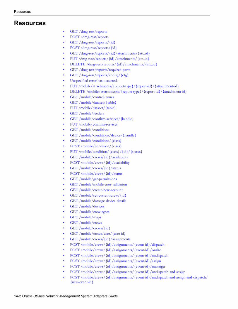
Resources
Resources• GET /dmg-rest/reports
• POST /dmg-rest/reports• GET /dmg-rest/reports/{id}• POST /dmg-rest/reports/{id}
• GET /dmg-rest/reports/{id}/attachments/{att_id}• PUT /dmg-rest/reports/{id}/attachments/{att_id}• DELETE /dmg-rest/reports/{id}/attachments/{att_id}
• GET /dmg-rest/reports/required-parts• GET /dmg-rest/reports/config/{cfg}• Unspecified error has occurred.
• PUT /mobile/attachments/{report-type}/{report-id}/{attachment-id}• DELETE /mobile/attachments/{report-type}/{report-id}/{attachment-id}• GET /mobile/control-zones
• GET /mobile/dataset/{table}• PUT /mobile/dataset/{table}• GET /mobile/feeders
• GET /mobile/confirm-services/{handle}• PUT /mobile/confirm-services• GET /mobile/conditions
• GET /mobile/conditions/device/{handle}• GET /mobile/conditions/{class}• POST /mobile/condition/{class}
• PUT /mobile/condition/{class}/{id}/{status}• GET /mobile/crews/{id}/availability• POST /mobile/crews/{id}/availability
• GET /mobile/crews/{id}/status• POST /mobile/crews/{id}/status• GET /mobile/get-permissions
• GET /mobile/mobile-user-validation• GET /mobile/create-new-account
• GET /mobile/set-current-crew/{id}• GET /mobile/damage-device-details• GET /mobile/devices
• GET /mobile/crew-types• GET /mobile/maps• GET /mobile/crews
• GET /mobile/crews/{id}• GET /mobile/crews/user/{user id}• GET /mobile/crews/{id}/assignments
• POST /mobile/crews/{id}/assignments/{event-id}/dispatch• POST /mobile/crews/{id}/assignments/{event-id}/onsite• POST /mobile/crews/{id}/assignments/{event-id}/undispatch
• POST /mobile/crews/{id}/assignments/{event-id}/assign• POST /mobile/crews/{id}/assignments/{event-id}/unassign• POST /mobile/crews/{id}/assignments/{event-id}/undispatch-and-assign
• POST /mobile/crews/{id}/assignments/{event-id}/undispatch-and-assign-and-dispatch/{new-event-id}
14-2 Oracle Utilities Network Management System Adapters Guide

Resources
• GET /trbl-rest/events/{id}• POST /trbl-rest/events/{id}
• PUT /trbl-rest/events/{id}/trouble-queue• GET /trbl-rest/config/{cfg}• GET /mobile/version
• GET /mobile/application-version/{name}/{arch}• GET /mobile/application-versions/{name}/{arch}• GET /mobile/application/{name}/{arch}
• GET /mobile/application/{name}/{arch}/{version}• POST /mobile/mobile-user-logout• PUT /mobile/user-profile/{field-name}/{value}
• GET /mobile/device/{id}/info• GET /mobile/device/{id}/operate/{operation}/phases/{phases}/time/{time}• GET /mobile/device/{id}/lookahead/{operation}/{phases}
• POST /mobile/device/statuses• GET /mobile/{id}/customers• GET /mobile/maps/{mapname}
• GET /mobile/file/:dir_name /:file_name• POST /mobile/crew• GET /mobile/condition/{class}/{id}
• PUT /mobile/condition/{class}/{id}/text/{text}• DELETE /mobile/condition/{class}/{id}• GET /mobile/switch-sheets/assignments/{crew-key}
• POST /mobile/switch-sheets/{sheet-class}/{sheet-index}/steps/{step-class}/{step-index}• POST /mobile/switch-sheets/{sheet-class}/{sheet-index}/steps/{step-class}/{step-
index}/details• POST /mobile/switch-sheets/{sheet-class}/{sheet-index}/transition
• GET /mobile/switch-sheets/{sheet-class}/{sheet-index}/report• GET /mobile/switch-sheets/{sheet-class}/{sheet-index}/document/{document-id}• PUT /mobile/switch-sheets/{sheet-class}/{sheet-index}/document
• POST /mobile/hlm• GET /mobile/nms-status
• GET /mobile/lookup-types/{table}/{keyField}/{valueField}• GET /mobile/nms-status• POST /trbl-rest/event/{id}/log
• POST /trbl-rest/event/{id}/log-once• POST /trbl-rest/event/{id}/state-transition• GET /trbl-rest/events/{id}/customers
• POST /trbl-rest/user-log• POST /trbl-rest/user-log-once
REST API 14-3

Resources
GET /dmg-rest/reportsRetrieves damage reports or given query parameters.
Supported query types:
• Location - returns damage reports within the given radius from the specified location. Parameters lat, long, and rad are required for this query type.
• Patrol - returns damage reports associated with the given patrol event. Parameter patrol is request for this query type.
• Event - returns damage reports associated with the given event. Parameter event is request for this query type.
Note: parameters from different query types cannot be mixed (for example, it is not possible to request damage reports for a patrol event which are location near specific point).
Parameters
Success Response• Code: 200
Content: Array of JSON objects representing damage reports
Error Response• Code: 401 Unauthorized
User is not authorized to perform the request.
• Code: 500 Internal Server Error
Unspecified error has occurred.
Name Type Description
lat query[floating-point] Latitude of the location.
long query[floating-point] Longitude of the location.
rad query[floating-point] Radius in meters.
event query[integer] Event index.
patrol query[integer] Patrol event index.
device query[string] Device handle.
14-4 Oracle Utilities Network Management System Adapters Guide

Resources
POST /dmg-rest/reportsCreates new damage report.
Parameters
Success Response• Code: 201 Created
Content: JSON representation of the created damage report
Error Response• Code: 401 Unauthorized
User is not authorized to perform the request.
• Code: 500 Internal Server Error
Unspecified error has occurred.
GET /dmg-rest/reports/{id}Retrieves existing damage report by id.
Parameters
Success Response• Code: 200
Content: JSON or XML representation of a damage report
Error Response• Code: 204 No Content
Damage report with the given identifier were not found.
• Code: 401 Unauthorized
User is not authorized to perform the request.
• Code: 500 Internal Server Error
Unspecified error has occurred.
Name Type Description
unnamedrequired
dataa
a. ‘data’ parameters represent the body of a POST or PUT request. Such parameters do not have a name thus ‘unnamed’ in the list of parameters.
JSON representation of a damage report.
action query[string] State transition action when saving damage report (for example, assess).
Name Type Description
idrequired
path[integer] Damage report identifier.
REST API 14-5

Resources
POST /dmg-rest/reports/{id}Updates existing damage report.
Parameters
Success Response• Code: 200
Content: JSON representation of a damage report
Error Response• Code: 204 No Content
Damage report with the given identifier were not found.
• Code: 401 Unauthorized
User is not authorized to perform the request.
• Code: 500 Internal Server Error
Unspecified error has occurred.
GET /dmg-rest/reports/{id}/attachments/{att_id}Retrieves content of an existing damage report attachment.
Parameters
Success Response• Code: 200
Content: Binary attachment data (e.g., image)
Name Type Description
idrequired
path[integer] Damage report identifier.
action query[string] State transition action when saving damage report (for example, assess).
unnamedrequired
data JSON representation of a damage report
Name Type Description
idrequired
path[integer] Damage report identifier.
att_idrequired
path[string] Attachment name/identifier.
w query[string] If image, reduce width to w pixels.
h query[string] If image, reduce height to h pixels.
14-6 Oracle Utilities Network Management System Adapters Guide

Resources
Error Response• Code: 204 No Content.
Requested attachment does not exist.
• Code: 401 Unauthorized
User is not authorized to perform the request.
• Code: 500 Internal Server Error
Unspecified error has occurred.
PUT /dmg-rest/reports/{id}/attachments/{att_id}Uploads contents of a damage report attachment.
Note: This API only uploads the binary attachment data to the server. The list of attachments is part of the damage report itself.
Parameters
Success Response• Code: 201 Created
Error Response• Code: 204 No Content.
Requested attachment does not exist.
• Code: 401 Unauthorized
User is not authorized to perform the request.
• Code: 500 Internal Server Error
Unspecified error has occurred.
Name Type Description
idrequired
path[integer] Damage report identifier.
att_idrequired
path[string] Attachment name/identifier.
unnamedrequired
data Attachment data.
REST API 14-7

Resources
DELETE /dmg-rest/reports/{id}/attachments/{att_id}Deletes a damage report attachment.
Parameters
Success Response• Code: 204 No Content
Error Response• Code: 401 Unauthorized
User is not authorized to perform the request.
• Code: 500 Internal Server Error
Unspecified error has occurred.
GET /dmg-rest/reports/required-partsRetrieves list of required parts and materials which are configured in NMS.
ParametersNone.
Success Response• Code: 200
Content: Array of JSON objects representing all known required parts
Error Response• Code: 401 Unauthorized
User is not authorized to perform the request.
• Code: 500 Internal Server Error
Unspecified error has occurred.
Name Type Description
idrequired
path[integer] Damage report identifier.
att_idrequired
path[string] Attachment name/identifier.
14-8 Oracle Utilities Network Management System Adapters Guide
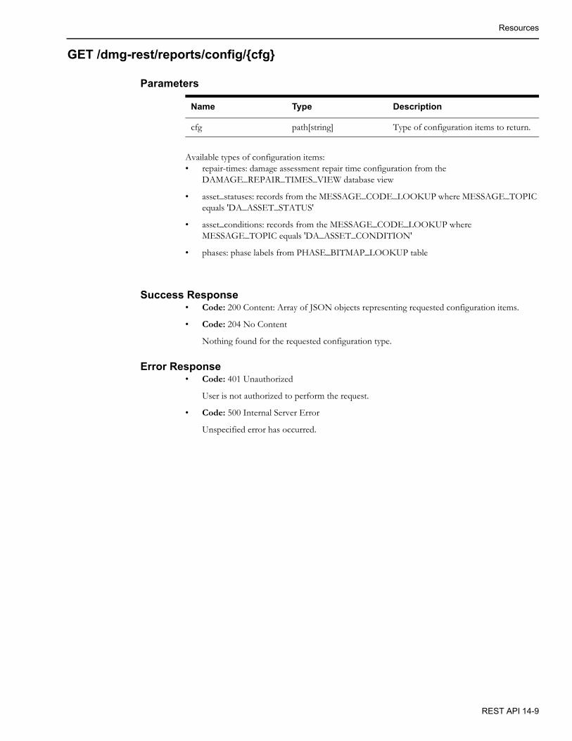
Resources
GET /dmg-rest/reports/config/{cfg}
Parameters
Available types of configuration items:• repair-times: damage assessment repair time configuration from the
DAMAGE_REPAIR_TIMES_VIEW database view
• asset_statuses: records from the MESSAGE_CODE_LOOKUP where MESSAGE_TOPIC equals 'DA_ASSET_STATUS'
• asset_conditions: records from the MESSAGE_CODE_LOOKUP where MESSAGE_TOPIC equals 'DA_ASSET_CONDITION'
• phases: phase labels from PHASE_BITMAP_LOOKUP table
Success Response• Code: 200 Content: Array of JSON objects representing requested configuration items.
• Code: 204 No Content
Nothing found for the requested configuration type.
Error Response• Code: 401 Unauthorized
User is not authorized to perform the request.
• Code: 500 Internal Server Error
Unspecified error has occurred.
Name Type Description
cfg path[string] Type of configuration items to return.
REST API 14-9

Resources
GET /mobile/attachments/{report-type}/{report-id}/{attachment-id}Get attachment from the nms_attachments table for the given report.
Parameters
ResponseContent: byte[] of the attachment data
• Code: 200 The return value will be the attachment.
• Code: 500 Unspecified service error has occurred.
Content may describe the issue encountered.
Name Type Description
report-type path[string] Report type to get attachment for; for example, DA or TE.
report-idrequired
path[integer] Report index to get attachment for
attachment-idrequired
path[string] Attachment ID of requested attachment.
woptional
query[Integer] If image, reduce the width to this value, if not provided, no reduction.
hoptional
query[Integer] If image, reduce the height to this value, if not provided, no reduction.
14-10 Oracle Utilities Network Management System Adapters Guide
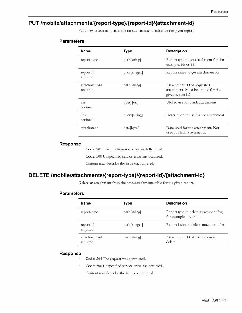
Resources
PUT /mobile/attachments/{report-type}/{report-id}/{attachment-id}Put a new attachment from the nms_attachments table for the given report.
Parameters
Response• Code: 201 The attachment was successfully saved
• Code: 500 Unspecified service error has occurred.
Content may describe the issue encountered.
DELETE /mobile/attachments/{report-type}/{report-id}/{attachment-id}Delete an attachment from the nms_attachments table for the given report.
Parameters
Response• Code: 204 The request was completed.
• Code: 500 Unspecified service error has occurred.
Content may describe the issue encountered.
Name Type Description
report-type path[string] Report type to get attachment for; for example, DA or TE.
report-idrequired
path[integer] Report index to get attachment for
attachment-idrequired
path[string] Attachment ID of requested attachment. Must be unique for the given report ID.
urioptional
query[uri] URI to use for a link attachment
descoptional
query[string] Description to use for the attachment.
attachment data[byte[]] Data used for the attachment. Not used for link attachments.
Name Type Description
report-type path[string] Report type to delete attachment for; for example, DA or TE.
report-idrequired
path[integer] Report index to delete attachment for
attachment-idrequired
path[string] Attachment ID of attachment to delete.
REST API 14-11
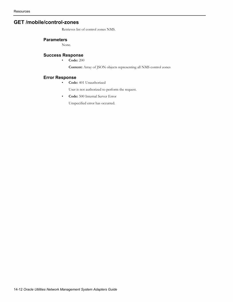
Resources
GET /mobile/control-zonesRetrieves list of control zones NMS.
ParametersNone.
Success Response• Code: 200
Content: Array of JSON objects representing all NMS control zones
Error Response• Code: 401 Unauthorized
User is not authorized to perform the request.
• Code: 500 Internal Server Error
Unspecified error has occurred.
14-12 Oracle Utilities Network Management System Adapters Guide

Resources
GET /mobile/dataset/{table}Get records from the given table where the key-field matches the key-value based on the match type. The table must appear in the mobile_datasets whilelist table.
Parameters
Name Type Description
tablerequired
path[string] Table name to return record for.
key-fieldrequired
query[string] Field name to use as the selection criteria for the returned records.
key-valuerequired
query[string] Value matched to the key-field as the selection criteria for the returned records. The match is case insensitive.
match-typeoptional
query[string] The match type to use. Options:equals, not-equals, like, not-like, or all.Default value is equals.
max-rowsoptional
query[integer] Limit the number of rows returned to this value. Default value is 100.
lat-longoptional
query[boolean] Adds additional _latitude,_longitude, and _location attributes to the records returned.
The dataset must contain dev_cls and dev_idx (handle class and index of targeted object) attributes to support this option. The _location attribute will be derived from the location attribute from the base attribute table as identified in the classes table.
The _latitude and _longitude attributes will be derived based on these processes in order:
1. Use a LATITUDE and LONGITUDE value from the dataset table or view.
2. Use the X_COORD and Y_COORD from the dataset table or view and then convert it to latitude and longitude values.
3. Get the first coordinate system zero coordinate for the given DEV_CLS/DEV_IDX object from the point coordinates table and convert it to latitude and longitude values.
4. Get the location object that the DEV_CLS/DEV_IDX object belongs to from the network components, object instances, or network nodes table, then get the reference coordinates from the locations table and convert them to latitude and longitude.
5. Go to the attribute table associated with the DEV_CLSand find a record matching the DEV_CLS/DEV_IDX, and if it has latitude and longitude fields, use them.
REST API 14-13

Resources
Response• Code: 200 The return value will a list of record sets.
• Code: 500 Unspecified service error has occurred.
Content may describe the issue encountered.
PUT /mobile/dataset/{table}Replace records for the given table where the key-field equals the key-value. The table must appear in the mobile_datasets whilelist table.
Parameters
Success Response• Code: 200: OK
Error Response• Code: 500: Internal Server Error
Content may describe the issue encountered.
Name Type Description
tablerequired
path[string] Table name to update record for.
key-fieldrequired
query[string] Field name to use as the selection criteria for the returned records.
key-valuerequired
query[string] Value matched to the key-field as the selection criteria for the returned records.
datarequired
data List of records (EBJResultSet) to replace in the database dataset with selection_set, column_names and serialVersionUID set. Column widths and type not required.
14-14 Oracle Utilities Network Management System Adapters Guide

Resources
GET /mobile/feedersRetrieves list of feeders with attributes (h_cls, h_idx, feeder_name, substation_name, color, group_num, and abnormal_color).
ParametersNone.
Success Response• Code: 200
• Content: Array of JSON objects representing all NMS feeders
Error Response• Code: 401 Unauthorized
User is not authorized to perform the request.
• Code: 500 Internal Server Error
Unspecified error has occurred.
GET /mobile/confirm-services/{handle}Get a list of customers with secondary and service outage details for the given device or event handle.
Parameters
Response• Code: 200 The return value will be a object of customer IDs with a list of customer details.
The details will include one for the customerId and additional customer details is the customer is involved with an existing service or secondary event.
• Code: 204 No customers for the given device or event handle
• Code: 500 Unspecified service error has occurred
Name Type Description
handlerequired
path[Handle string] Handle of a device or event to get the customers for.
max-supply-nodesoptional
query[integer] Maximum number of supply nodes to return the customer list from. Defaults to 100.
REST API 14-15

Resources
PUT /mobile/confirm-servicesUpdate service and secondary events for the given list of services.
Parameters
Example[{"cust_id":"2001637-2001637-2001637","address":"10586 MOGADORE AVE NW, Lake Twp., OH, 44685","ctype":"","device":{"class_number":207,"app":0,"instance_number":2217},"event":{"class_number":800,"app":0,"instance_number":2750},"bitmask":0}]
Success Response• Code: 200: OK
• Content: OK
Error Response• Code: 401 Unauthorized
User is not authorized to perform the request
• Code: 500 Internal Server Error
Unspecified service error has occurred
Name Type Description
actionrequired
query[service, secondary, restore, groupable]
Action to perform on the list of customer updates.
as-useroptional
query[string] User to do the API call as. The calling user must have "Allow as-user Parameter" mobile permission.
updatesrequired
data[updates] A list of customer service updates.
14-16 Oracle Utilities Network Management System Adapters Guide
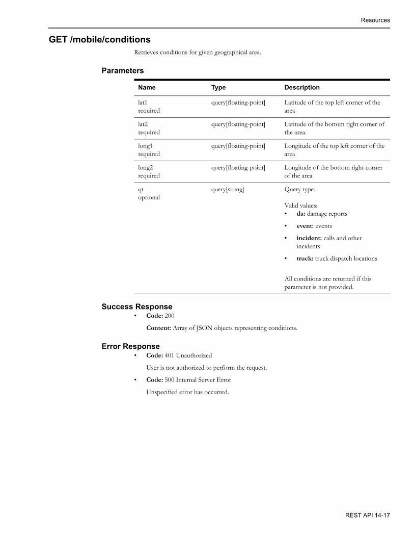
Resources
GET /mobile/conditionsRetrieves conditions for given geographical area.
Parameters
Success Response• Code: 200
Content: Array of JSON objects representing conditions.
Error Response• Code: 401 Unauthorized
User is not authorized to perform the request.
• Code: 500 Internal Server Error
Unspecified error has occurred.
Name Type Description
lat1required
query[floating-point] Latitude of the top left corner of the area
lat2required
query[floating-point] Latitude of the bottom right corner of the area.
long1required
query[floating-point] Longitude of the top left corner of the area
long2required
query[floating-point] Longitude of the bottom right corner of the area
qtoptional
query[string] Query type.
Valid values:• da: damage reports
• event: events
• incident: calls and other incidents
• truck: truck dispatch locations
All conditions are returned if this parameter is not provided.
REST API 14-17

Resources
GET /mobile/conditions/device/{handle}Returns a list of conditions on the specified device handle
Parameters
Response• Code: 200 The return data will be a list of conditions.
GET /mobile/conditions/{class}Returns a list of conditions for the requesting authentication user name of the given condition class.
Parameters
Response• 200: The return data will be a list of conditions
POST /mobile/condition/{class}Create a condition with the given class, status, and text for the given device.
Parameters
Response• 200: Returns the condition index of the new condition created.
Name Type Description
handlerequired
path[hande] Handle of the device to get conditions for; for example, 148.1001.
Name Type Description
class path[string] Name of the class of conditions.
Name Type Description
:class path[string] Name of the class of conditions
status query[integer] Status of the class
dev-class query[integer] Handle Class number of the device
dev-index query[integer] Handle Index number of the device
text path[string] Text to be saved with the condition
as-useroptional
query[string] User to do the API call as. The calling user must have “Allow as-user Parameter” mobile permission.
14-18 Oracle Utilities Network Management System Adapters Guide

Resources
PUT /mobile/condition/{class}/{id}/{status}Updates the given condition's status to the given status.
Parameters
Response• 200: No content returned
GET /mobile/crews/{id}/availabilityRetrieves the current availability information for a crew.
Parameters
Success Response• Code: 200
Content: Crew availability information in JSON format.
Error Response• Code: 401 Unauthorized
User is not authorized to perform the request.
• Code: 500 Internal Server Error
Unspecified error has occurred.
Name Type Description
class path[string] Class Name of the condition
id path[integer] Id of the condition
status path[integer] The new status of the condition
as-useroptional
query[string] User to do the API call as. The calling user must have “Allow as-user Parameter” mobile permission.
Name Type Description
idrequired
path[integer] Crew key.
REST API 14-19
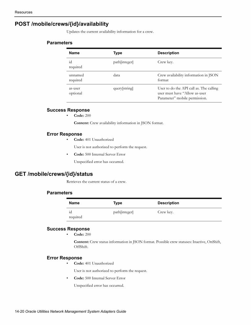
Resources
POST /mobile/crews/{id}/availabilityUpdates the current availability information for a crew.
Parameters
Success Response• Code: 200
Content: Crew availability information in JSON format.
Error Response• Code: 401 Unauthorized
User is not authorized to perform the request.
• Code: 500 Internal Server Error
Unspecified error has occurred.
GET /mobile/crews/{id}/statusRetrieves the current status of a crew.
Parameters
Success Response• Code: 200
Content: Crew status information in JSON format. Possible crew statuses: Inactive, OnShift, OffShift.
Error Response• Code: 401 Unauthorized
User is not authorized to perform the request.
• Code: 500 Internal Server Error
Unspecified error has occurred.
Name Type Description
idrequired
path[integer] Crew key.
unnamedrequired
data Crew availability information in JSON format
as-useroptional
query[string] User to do the API call as. The calling user must have “Allow as-user Parameter” mobile permission.
Name Type Description
idrequired
path[integer] Crew key.
14-20 Oracle Utilities Network Management System Adapters Guide

Resources
POST /mobile/crews/{id}/statusUpdates current status of a crew.
Parameters
Success Response• Code: 200
Content: Crew status information in JSON format.
Error Response• Code: 401 Unauthorized
User is not authorized to perform the request.
• Code: 500 Internal Server Error
Unspecified error has occurred.
Name Type Description
idrequired
path[integer] Crew key.
unnamedrequired
data Crew status information in JSON format.Valid crew statuses:• OnShift
• OffShift
• Inactive
as-useroptional
query[string] User to do the API call as. The calling user must have “Allow as-user Parameter” mobile permission.
REST API 14-21
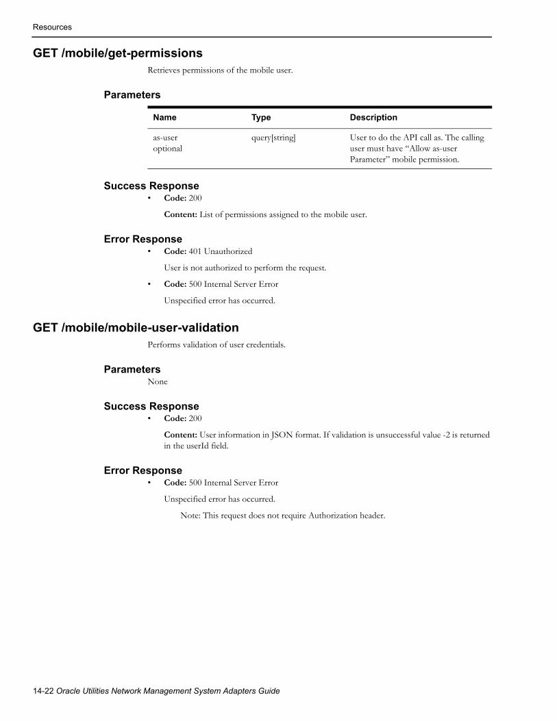
Resources
GET /mobile/get-permissionsRetrieves permissions of the mobile user.
Parameters
Success Response• Code: 200
Content: List of permissions assigned to the mobile user.
Error Response• Code: 401 Unauthorized
User is not authorized to perform the request.
• Code: 500 Internal Server Error
Unspecified error has occurred.
GET /mobile/mobile-user-validationPerforms validation of user credentials.
ParametersNone
Success Response• Code: 200
Content: User information in JSON format. If validation is unsuccessful value -2 is returned in the userId field.
Error Response• Code: 500 Internal Server Error
Unspecified error has occurred.
Note: This request does not require Authorization header.
Name Type Description
as-useroptional
query[string] User to do the API call as. The calling user must have “Allow as-user Parameter” mobile permission.
14-22 Oracle Utilities Network Management System Adapters Guide
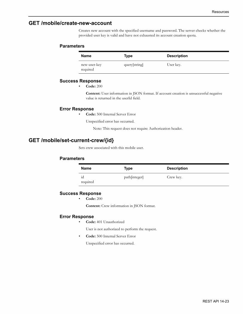
Resources
GET /mobile/create-new-accountCreates new account with the specified username and password. The server checks whether the provided user key is valid and have not exhausted its account creation quota.
Parameters
Success Response• Code: 200
Content: User information in JSON format. If account creation is unsuccessful negative value is returned in the userId field.
Error Response• Code: 500 Internal Server Error
Unspecified error has occurred.
Note: This request does not require Authorization header.
GET /mobile/set-current-crew/{id}Sets crew associated with this mobile user.
Parameters
Success Response• Code: 200
Content: Crew information in JSON format.
Error Response• Code: 401 Unauthorized
User is not authorized to perform the request.
• Code: 500 Internal Server Error
Unspecified error has occurred.
Name Type Description
new-user-keyrequired
query[string] User key.
Name Type Description
idrequired
path[integer] Crew key.
REST API 14-23

Resources
GET /mobile/damage-device-detailsRetrieves device information for given alias.
Parameters
Success Response• Code: 200
Content: Device information in JSON format.
Error Response• Code: 401 Unauthorized
User is not authorized to perform the request.
• Code: 500 Internal Server Error
Unspecified error has occurred.
PUT /mobile/device/assessUpdates the passed conductors to the assessed state.
Parameters
Response• 200: No content returned
PUT /mobile/device/unassessUpdates the passed conductors to clear the assessed state.
Parameters
Response• 200: No content returned
Name Type Description
device-idrequired
query[string] Device alias.
Name Type Description
handlesrequired
data The conductor handles to update.
Name Type Description
handlesrequired
data The conductor handles to update.
14-24 Oracle Utilities Network Management System Adapters Guide

Resources
GET /mobile/devicesRetrieves information for devices matching given device alias search string.
Parameters
Success Response• Code: 200
Content: Array of JSON objects representing device information.
Error Response• Code: 401 Unauthorized
User is not authorized to perform the request.
• Code: 500 Internal Server Error
Unspecified error has occurred.
GET /mobile/crew-typesRetrieves list of crew types configured in NMS.
ParametersNone.
Success Response• Code: 200
Content: Array of JSON objects representing crew types.
Error Response• Code: 401 Unauthorized
User is not authorized to perform the request.
• Code: 500 Internal Server Error
Unspecified error has occurred.
Name Type Description
device-idrequired
query[string] Device alias search string (can contain SQL wildcard characters).
REST API 14-25
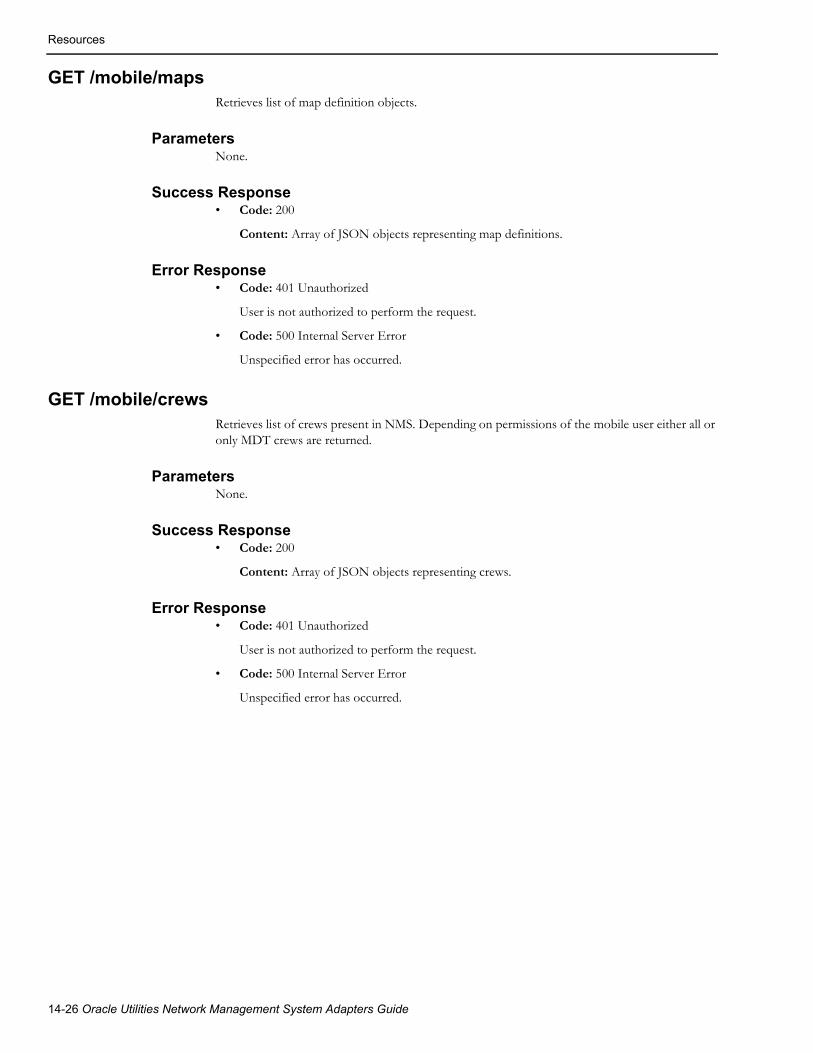
Resources
GET /mobile/mapsRetrieves list of map definition objects.
ParametersNone.
Success Response• Code: 200
Content: Array of JSON objects representing map definitions.
Error Response• Code: 401 Unauthorized
User is not authorized to perform the request.
• Code: 500 Internal Server Error
Unspecified error has occurred.
GET /mobile/crewsRetrieves list of crews present in NMS. Depending on permissions of the mobile user either all or only MDT crews are returned.
ParametersNone.
Success Response• Code: 200
Content: Array of JSON objects representing crews.
Error Response• Code: 401 Unauthorized
User is not authorized to perform the request.
• Code: 500 Internal Server Error
Unspecified error has occurred.
14-26 Oracle Utilities Network Management System Adapters Guide
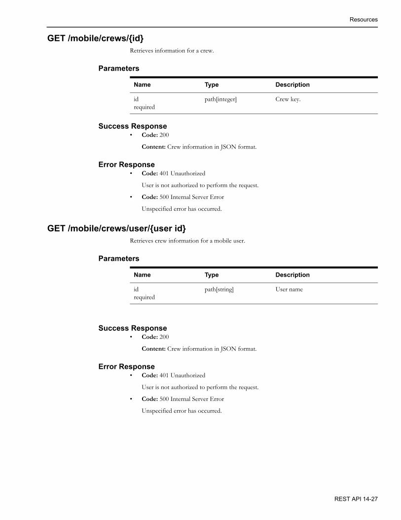
Resources
GET /mobile/crews/{id}Retrieves information for a crew.
Parameters
Success Response• Code: 200
Content: Crew information in JSON format.
Error Response• Code: 401 Unauthorized
User is not authorized to perform the request.
• Code: 500 Internal Server Error
Unspecified error has occurred.
GET /mobile/crews/user/{user id}Retrieves crew information for a mobile user.
Parameters
Success Response• Code: 200
Content: Crew information in JSON format.
Error Response• Code: 401 Unauthorized
User is not authorized to perform the request.
• Code: 500 Internal Server Error
Unspecified error has occurred.
Name Type Description
idrequired
path[integer] Crew key.
Name Type Description
idrequired
path[string] User name
REST API 14-27

Resources
GET /mobile/crews/{id}/assignmentsRetrieves list of current assignments for a crew.
Parameters
Success Response• Code: 200
Content: Array of JSON objects representing crew assignments.
Error Response• Code: 401 Unauthorized
User is not authorized to perform the request.
• Code: 500 Internal Server Error
Unspecified error has occurred.
POST /mobile/crews/{id}/assignments/{event-id}/dispatchPlaces a crew en-route to an event.
Parameters
Success Response• Code: 200
Content: Array of JSON objects representing crew assignments.
Name Type Description
idrequired
path[integer] Crew key.
Name Type Description
idrequired
path[integer] Crew key.
event-idrequired
path[integer] Event index.
as-useroptional
query[string] User to do the API call as. The calling user must have “Allow as-user Parameter” mobile permission.
timeoptional
query[long] Time the assignment change occurred. Zero means current time. The value is the number of milliseconds since 1 January 1970 00:00:00.000
14-28 Oracle Utilities Network Management System Adapters Guide

Resources
Error Response• Code: 401 Unauthorized
User is not authorized to perform the request.
• Code: 500 Internal Server Error
Unspecified error has occurred.
POST /mobile/crews/{id}/assignments/{event-id}/onsitePlaces a crew onsite for an event.
Parameters
Success Response• Code: 200
Content: Array of JSON objects representing crew assignments.
Error Response• Code: 401 Unauthorized
User is not authorized to perform the request.
• Code: 500 Internal Server Error
Unspecified error has occurred.
Name Type Description
idrequired
path[integer] Crew key.
event-idrequired
path[integer] Event index.
as-useroptional
query[string] User to do the API call as. The calling user must have “Allow as-user Parameter” mobile permission.
timeoptional
query[long] Time the assignment change occurred. Zero means current time. The value is the number of milliseconds since 1 January 1970 00:00:00.000
REST API 14-29

Resources
POST /mobile/crews/{id}/assignments/{event-id}/undispatchMakes a crew no longer en-route or onsite for an event.
Parameters
Success Response• Code: 200
Content: Array of JSON objects representing crew assignments.
Error Response• Code: 401 Unauthorized
User is not authorized to perform the request.
• Code: 500 Internal Server Error
Unspecified error has occurred.
Name Type Description
idrequired
path[integer] Crew key.
event-idrequired
path[integer] Event index.
as-useroptional
query[string] User to do the API call as. The calling user must have “Allow as-user Parameter” mobile permission.
timeoptional
query[long] Time the assignment change occurred. Zero means current time. The value is the number of milliseconds since 1 January 1970 00:00:00.000
14-30 Oracle Utilities Network Management System Adapters Guide

Resources
POST /mobile/crews/{id}/assignments/{event-id}/assignAdds assignment of a crew to an event.
Parameters
Success Response• Code: 200
Content: Array of JSON objects representing crew assignments.
Error Response• Code: 401 Unauthorized
User is not authorized to perform the request.
• Code: 500 Internal Server Error
Unspecified error has occurred.
Name Type Description
idrequired
path[integer] Crew key.
event-idrequired
path[integer] Event index.
as-useroptional
query[string] User to do the API call as. Calling user must have “Allow as-user Parameter” mobile permission.
timeoptional
query[long] Time the assignment change occurred. Zero means current time. The value is the number of milliseconds since 1 January 1970 00:00:00.000
REST API 14-31

Resources
POST /mobile/crews/{id}/assignments/{event-id}/unassignRemoves assignment of a crew to an event.
Parameters
Success Response• Code: 200
Content: Array of JSON objects representing remaining crew assignments.
Error Response• Code: 401 Unauthorized
User is not authorized to perform the request.
• Code: 500 Internal Server Error
Unspecified error has occurred.
Name Type Description
idrequired
path[integer] Crew key.
event-idrequired
path[integer] Event index.
as-useroptional
query[string] User to do the API call as. The calling user must have “Allow as-user Parameter” mobile permission.
timeoptional
query[long] Time the assignment change occurred. Zero means current time. The value is the number of milliseconds since 1 January 1970 00:00:00.000
suspendoptional
query[string] Whether to suspend the event and crew, when applicable. If no other crews are assigned to the event, it will transition to the SUS state. If the crew is not assigned to other events, the crew will become Suspended.
14-32 Oracle Utilities Network Management System Adapters Guide

Resources
POST /mobile/crews/{id}/assignments/{event-id}/undispatch-and-assignMakes a crew no longer en-route or onsite for an event but keeps the assignment of the crew to the event.
Parameters
Success Response• Code: 200
Content: Array of JSON objects representing crew assignments.
Error Response• Code: 401 Unauthorized
User is not authorized to perform the request.
• Code: 500 Internal Server Error
Unspecified error has occurred.
Name Type Description
idrequired
path[integer] Crew key.
event-idrequired
path[integer] Event index.
as-useroptional
query[string] User to do the API call as. The calling user must have “Allow as-user Parameter” mobile permission.
timeoptional
query[long] Time the assignment change occurred. Zero means current time. The value is the number of milliseconds since 1 January 1970 00:00:00.000
REST API 14-33

Resources
POST /mobile/crews/{id}/assignments/{event-id}/undispatch-and-assign-and-dispatch/{new-event-id}
Places crew en-route to a different event.
Parameters
Success Response• Code: 200
Content: Array of JSON objects representing crew assignments.
Error Response• Code: 401 Unauthorized
User is not authorized to perform the request.
• Code: 500 Internal Server Error
Unspecified error has occurred.
Name Type Description
idrequired
path[integer] Crew key.
event-idrequired
path[integer] Original event index.
new-event-idrequired
path[integer] New event index.
as-useroptional
query[string] User to do the API call as. The calling user must have “Allow as-user Parameter” mobile permission.
timeoptional
query[long] Time the assignment change occurred. Zero means current time. The value is the number of milliseconds since 1 January 1970 00:00:00.000
14-34 Oracle Utilities Network Management System Adapters Guide

Resources
GET /trbl-rest/events/{id}Retrieves an event with the given index.
Parameters
Success Response• Code: 200
Content: JSON representation of an NMS event or the NMS Event and TroubleEvent.
Error Response• Code: 204 No Content
Event with the given index was not found.
• Code: 401 Unauthorized
User is not authorized to perform the request.
• Code: 500 Internal Server Error
Unspecified error has occurred.
Name Type Description
idrequired
path[integer] Event index.
max_calls query[integer] Maximum number of calls to return about the event. Default: 10.
extended query[char] If value is ‘Y’, will return the NMS TroubleEvent structure in addition to the Event structure.
REST API 14-35
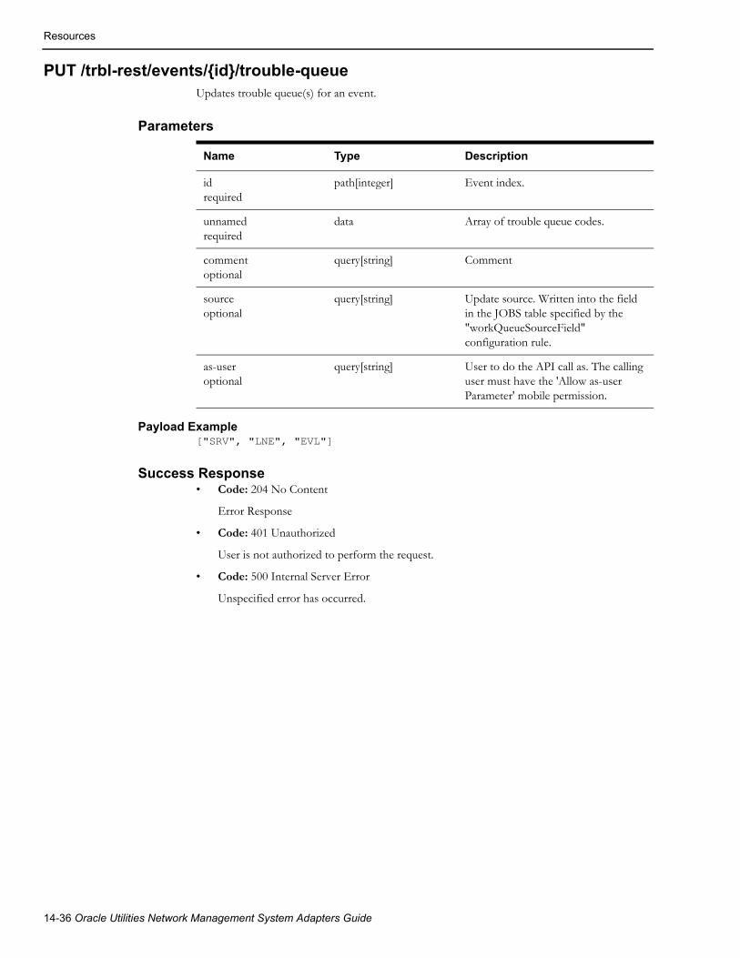
Resources
PUT /trbl-rest/events/{id}/trouble-queueUpdates trouble queue(s) for an event.
Parameters
Payload Example["SRV", "LNE", "EVL"]
Success Response• Code: 204 No Content
Error Response
• Code: 401 Unauthorized
User is not authorized to perform the request.
• Code: 500 Internal Server Error
Unspecified error has occurred.
Name Type Description
idrequired
path[integer] Event index.
unnamedrequired
data Array of trouble queue codes.
commentoptional
query[string] Comment
sourceoptional
query[string] Update source. Written into the field in the JOBS table specified by the "workQueueSourceField" configuration rule.
as-useroptional
query[string] User to do the API call as. The calling user must have the 'Allow as-user Parameter' mobile permission.
14-36 Oracle Utilities Network Management System Adapters Guide
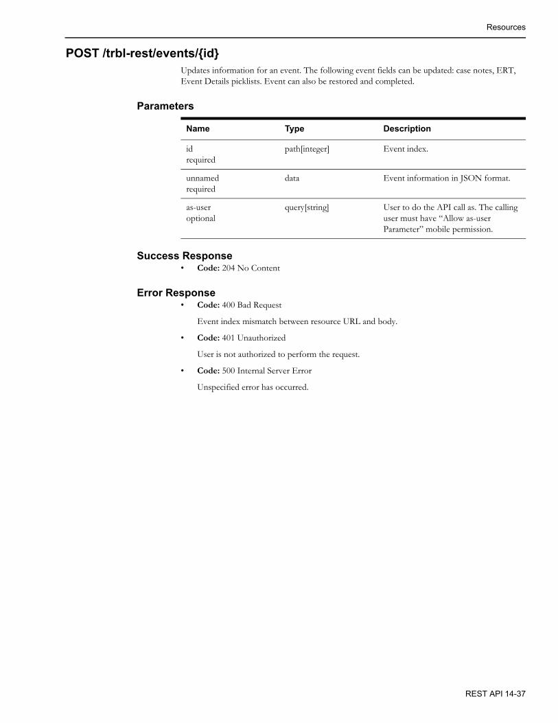
Resources
POST /trbl-rest/events/{id}Updates information for an event. The following event fields can be updated: case notes, ERT, Event Details picklists. Event can also be restored and completed.
Parameters
Success Response• Code: 204 No Content
Error Response• Code: 400 Bad Request
Event index mismatch between resource URL and body.
• Code: 401 Unauthorized
User is not authorized to perform the request.
• Code: 500 Internal Server Error
Unspecified error has occurred.
Name Type Description
idrequired
path[integer] Event index.
unnamedrequired
data Event information in JSON format.
as-useroptional
query[string] User to do the API call as. The calling user must have “Allow as-user Parameter” mobile permission.
REST API 14-37

Resources
GET /trbl-rest/config/{cfg}Retrieves NMS Trouble Management configuration items.
Parameters
Success Response• Code: 200
Content: JSON representation of the requested configuration item.
Error Response• Code: 204 No Content
• Code: 401 Unauthorized
User is not authorized to perform the request.
• Code: 500 Internal Server Error
Unspecified error has occurred.
GET /mobile/versionReturns version information for the NMS Application Server and the NMS Mobile Server.
ParametersNone.
Success Response• Code: 200
Content: Version information for the NMS Application Server and the NMS Mobile Server including items like build date, build tag, project name, NMS version, and server host name.
Name Type Description
cfgoptional
path[string] Configuration type. One of the following:• picklist: event completion
choices, from the PICKLIST_GUI table.
• trouble-queue: trouble queue options, from the RAPID_REFERRAL table.
• crew-members: crew member type options, from the CREW_MEMBER_CLASSES table.
• te-state-actions: All act_key, act_name from the TE_STATE_ACTIONS configuration table. This can be used to determine which state transitions are valid for a given event.
14-38 Oracle Utilities Network Management System Adapters Guide

Resources
Error Response• Code: 401 Unauthorized
User is not authorized to perform the request
• Code: 500 Internal Server ErrorUnspecified error has occurred
GET /mobile/application-version/{name}/{arch}Returns the latest version number of the application for the given Application Name and Architecture.
Parameters
Response• Code: 200 The return data will be the latest application version number. If there is no version
available matching the app Name and App Architecture, a -1 is returned.
GET /mobile/application-versions/{name}/{arch}Returns a list of available version numbers of the application for the given Application Name and Architecture.
Parameters
Response• Code: 200 The return data will be a list of integers for the version numbers of the application
that are available. If there is no version available matching the app Name and App Architecture, an empty list is returned.
Name Type Description
name path[string] Name of the application (OMA).
arch path[string] Architecture of the application. Can be one of these values: ANDROID, IOS, WIN10, BROWSER
Name Type Description
name path[string] Name of the application (OMA).
arch path[string] Architecture of the application. Can be one of these values: ANDROID, IOS, WIN10, BROWSER
REST API 14-39

Resources
GET /mobile/application/{name}/{arch}Returns the latest version of the application for the given Application Name and Architecture in .zip format.
Parameters
Response• Code: 200 The return data will be the application in .zip format. If there is no version
available matching the app Name and App Architecture, an exception is returned.
GET /mobile/application/{name}/{arch}/{version}Returns the application for the given Application Name, Application version and Architecture in .zip format.
Parameters
Response• Code: 200 The return data will be the application in .zip format. If there is no application
matching the app Name, app Version and App Architecture, an exception is returned.
Name Type Description
name path[string] Name of the application (OMA).
arch path[string] Architecture of the application. Can be one of these values: ANDROID, IOS, WIN10, BROWSER.
Name Type Description
name path[string] Name of the application (OMA).
arch path[string] Architecture of the application. Can be one of these values: ANDROID, IOS, WIN10, BROWSER.
version path[integer] Version of the application.
14-40 Oracle Utilities Network Management System Adapters Guide

Resources
POST /mobile/mobile-user-logoutNotifies NMS that mobile user has logged out.
ParametersNone.
Success Response• Code: 204 No Content
Content: None
Error Response• Code: 401 Unauthorized
User is not authorized to perform the request.
• Code: 500 Internal Server Error
Unspecified error has occurred.
PUT /mobile/user-profile/{field-name}/{value}Updates the requesting users profile for the given field-name with the given value.
Parameters
Success Response• Code: 200
Content: User information including all profile value
Error Response• Code: 401 Unauthorized
User is not authorized to perform the request
• Code: 500 Internal Server ErrorUnspecified error has occurred
Name Type Description
field-namerequired
path[string] Profile field to update.Names include:
• First name
• Last name
• Phone
• Company
valuerequired
path[string] Value to set field to.
as-useroptional
query[string] User to do the API call as. The calling user must have “Allow as-user Parameter” mobile permission.
REST API 14-41

Resources
GET /mobile/device/{id}/infoReturns information about a given device given a device handle.
Parameters
Success Response• Code: 200
Content: Returns information about the device including alias, phases, closed phases, fully open flag, fully closed flag.
Error Response• Code: 401 Unauthorized
User is not authorized to perform the request
• Code: 500 Internal Server ErrorUnspecified error has occurred
Name Type Description
idrequired
path[string] The device handle in the format: class.index
14-42 Oracle Utilities Network Management System Adapters Guide
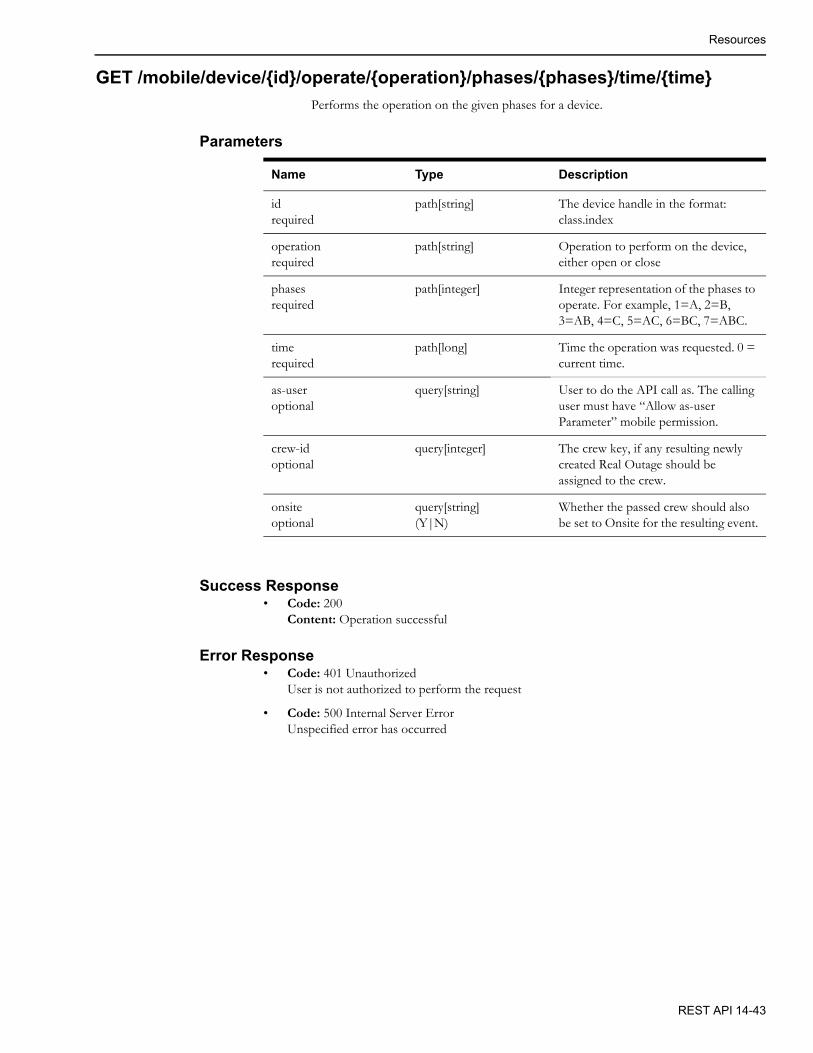
Resources
GET /mobile/device/{id}/operate/{operation}/phases/{phases}/time/{time}
Performs the operation on the given phases for a device.
Parameters
Success Response• Code: 200
Content: Operation successful
Error Response• Code: 401 Unauthorized
User is not authorized to perform the request
• Code: 500 Internal Server ErrorUnspecified error has occurred
Name Type Description
idrequired
path[string] The device handle in the format: class.index
operationrequired
path[string] Operation to perform on the device, either open or close
phasesrequired
path[integer] Integer representation of the phases to operate. For example, 1=A, 2=B, 3=AB, 4=C, 5=AC, 6=BC, 7=ABC.
timerequired
path[long] Time the operation was requested. 0 = current time.
as-useroptional
query[string] User to do the API call as. The calling user must have “Allow as-user Parameter” mobile permission.
crew-idoptional
query[integer] The crew key, if any resulting newly created Real Outage should be assigned to the crew.
onsiteoptional
query[string](Y|N)
Whether the passed crew should also be set to Onsite for the resulting event.
REST API 14-43

Resources
GET /mobile/device/{id}/lookahead/{operation}/{phases}Returns look ahead data about the requested operation on the given device.
Parameters
Success Response• Code: 200
Content: Returns Look Ahead Information including device information, alias, phases, customers affected by phase, ato customers affected by phase, condition, abnormal devices, critical customers, and DERs.
Error Response• Code: 401 Unauthorized
User is not authorized to perform the request
• Code: 500 Internal Server ErrorUnspecified error has occurred
Name Type Description
idrequired
path[string] The device handle in the format: class.index
operationrequired
path[string] Operation to perform on the device, either open or close
phasesrequired
path[integer] Integer representation of the phases to operate. For example, 1=A, 2=B, 3=AB, 4=C, 5=AC, 6=BC, 7=ABC.
14-44 Oracle Utilities Network Management System Adapters Guide

Resources
POST /mobile/device/statusesTake a list of object handles and return status of the objects.
Parameters
Response• 200: with JSON formatted return.
For example:
[{"deviceClass":126,"deviceIndex":1601,"nominalStatus":4,"currentStatus":4,"phases":0},{"deviceClass":126,"deviceIndex":1600,"nominalStatus":2,"currentStatus":0,"phases":0}]
The phase value is not supported yet will be returned as zero.
GET /mobile/{id}/customersGet a list of customers associated with a device id, including downstream devices. The call will take a device handle and a maximum number of SND's to get customers for.
Parameters
Response• Code: 200 The return value will be the list of customers in JSON double array format, where
the first record of the array will be the field names, and the rest of the array will be records of just values. It is up to the client to reformat the return value into true JSON objects.
Name Type Description
return-unknown-devices query[Y or N] Flag to indicate if devices that statuses were requested for that do not exist in the DDService, if set to Y, will be returned as objects with statuses set to -1, otherwise the unknown objects will not have any returned statuses.
handles data List of object handles to return statuses for.For example:
[{"deviceClass":126,"deviceIndex":1600},{"deviceClass":126,"deviceIndex":1601}]
Name Type Description
id path[handle string] Handle of the device to get customers for (e.g., 123.1001).
max-supply-nodes query[integer] Maximum number of SND's to get customers for.
REST API 14-45

Resources
GET /mobile/maps/{mapname}Returns the requested map in GeoJSON format.
Parameters
Success Response• Code: 200
Content: GeoJSON map.
Error Response• Code: 401 Unauthorized
User is not authorized to perform the request
• Code: 500 Internal Server ErrorUnspecified error has occurred
GET /mobile/file/:dir_name /:file_nameReturns the requested file from the given OPERATION_MODEL subdirectory in JSON format.
Parameters
Success Response• Code: 200
• Content: JSON file format
Error Response• Code: 401 Unauthorized
User is not authorized to perform the request
• Code: 500 Internal Server ErrorUnspecified error has occurred
Name Type Description
mapnamerequired
path[string] Name of the map to retrieve.
compressionoptional, defaults to ‘Y’
query[string] Indicates if the returned map is to be compressed or not by given value, Y or N.
Name Type Description
dir-name path[string] Name of the OPERATIONS_MODEL subdirector
file-name path[string] Name of the file to retrieve
14-46 Oracle Utilities Network Management System Adapters Guide

Resources
POST /mobile/crew
Update crew information. This is a stub API and not yet implemented.
Parameters
Success Response• Code: 200
Content: updated Mobile Crew information
Error Response• Code: 401 Unauthorized
User is not authorized to perform the request
• Code: 500 Internal Server ErrorsUnspecified error has occurred
GET /mobile/condition/{class}/{id}Return condition details given the condition class and id.
Parameters
Success Response• Code: 200
Content: Condition details including handle, affected device handle, node, who created, class name, partition, when created, condition status, phases, ncg, x/y coordinates, application string, text, condition specific data, and external id.
Error Response• Code: 401 Unauthorized
User is not authorized to perform the request
• Code: 500 Internal Server ErrorUnspecified error has occurred
Name Type Description
crew data Mobile Crew Information
as-useroptional
query[string] User to do the API call as. The calling user must have “Allow as-user Parameter” mobile permission.
Name Type Description
classrequired
path[string] Condition class name
idrequired
path[integer] Condition index
as-useroptional
query[string] User to do the API call as. The calling user must have “Allow as-user Parameter” mobile permission.
REST API 14-47
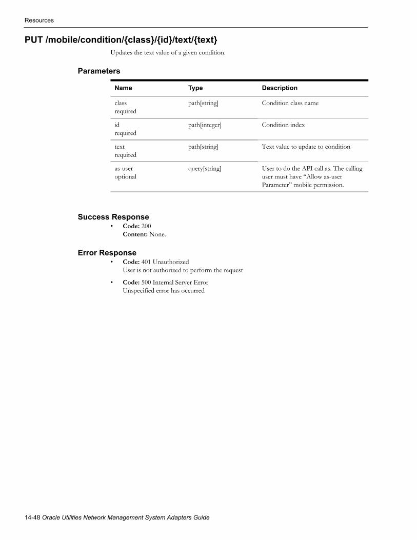
Resources
PUT /mobile/condition/{class}/{id}/text/{text}Updates the text value of a given condition.
Parameters
Success Response• Code: 200
Content: None.
Error Response• Code: 401 Unauthorized
User is not authorized to perform the request
• Code: 500 Internal Server ErrorUnspecified error has occurred
Name Type Description
classrequired
path[string] Condition class name
idrequired
path[integer] Condition index
textrequired
path[string] Text value to update to condition
as-useroptional
query[string] User to do the API call as. The calling user must have “Allow as-user Parameter” mobile permission.
14-48 Oracle Utilities Network Management System Adapters Guide

Resources
DELETE /mobile/condition/{class}/{id}Deletes the given condition.
Parameters
Success Response• Code: 200
Content: None.
Error Response• Code: 401 Unauthorized
User is not authorized to perform the request
• Code: 500 Internal Server ErrorUnspecified error has occurred
GET /mobile/switch-sheets/assignments/{crew-key}Returns a list of Mobile Switch Sheets associated to the given crew key
Parameters
Success Response• Code: 200
Content: A list of Mobile Switch Sheets, each sheet contains a sheet id, list of attribute/values, a list of steps, and a list of switch sheet associated document names and descriptions.
Error Response• Code: 401 Unauthorized
User is not authorized to perform the request
• Code: 500 Internal Server ErrorUnspecified error has occurred
Name Type Description
classrequired
path[string] Condition class name
idrequired
path[integer] Condition index
as-useroptional
query[string] User to do the API call as. The calling user must have “Allow as-user Parameter” mobile permission.
Name Type Description
crew-keyrequired
path[integer] Crew Key
REST API 14-49

Resources
POST /mobile/switch-sheets/{sheet-class}/{sheet-index}/steps/{step-class}/{step-index}
Updates status and fields of a switch sheet step.
Parameters
Success Response• Code: 200
Content: None.
Error Response• Code: 401 Unauthorized
User is not authorized to perform the request
• Code: 500 Internal Server ErrorUnspecified error has occurred
Name Type Description
sheet-classrequired
path[integer] Sheet class number
sheet-indexrequired
path[integer] Sheet index number
step-classrequired
path[integer] Step class number
step-indexrequired
path[integer] Step index number
actionoptional
query[string] Step transition action: complete_step, abort_step, fail_step
update-fieldsoptional
query[string] Step fields that have changes: comments, switching_desc, step_details, executed_time.
time query[long] Time when the switch step update occurred.
as-useroptional
query[string] User to do the API call as. The calling user must have “Allow as-user Parameter” mobile permission.
14-50 Oracle Utilities Network Management System Adapters Guide

Resources
POST /mobile/switch-sheets/{sheet-class}/{sheet-index}/steps/{step-class}/{step-index}/details
Updates comments, switching description, step details, mobile status, or mobile status date of a switch sheet step.
Parameters
Success Response• Code: 200
Content: None.
Error Response• Code: 401 Unauthorized
User is not authorized to perform the request
• Code: 500 Internal Server Error
Unspecified error has occurred
Name Type Description
sheet-classrequired
path[integer] Sheet class number
sheet-indexrequired
path[integer] Sheet index number
step-classrequired
path[integer] Step class number
step-indexrequired
path[integer] Step index number
update-fieldsoptional
query[string] Step fields that have changes, space separated:COMMENTS, SWITCHING_DESC, STEP_DETAILS, MOBILE_STATUS, MOBILE_STATUS_TIME.
as-useroptional
query[string] User to do the API call as. The calling user must have “Allow as-user Parameter” mobile permission.
switch-steprequired
data Switch step object that changes are applied to.
REST API 14-51
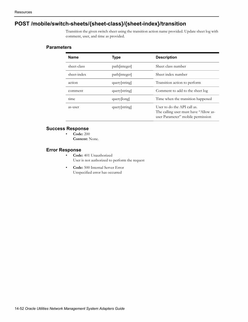
Resources
POST /mobile/switch-sheets/{sheet-class}/{sheet-index}/transitionTransition the given switch sheet using the transition action name provided. Update sheet log with comment, user, and time as provided.
Parameters
Success Response• Code: 200
Content: None.
Error Response• Code: 401 Unauthorized
User is not authorized to perform the request
• Code: 500 Internal Server ErrorUnspecified error has occurred
Name Type Description
sheet-class path[integer] Sheet class number
sheet-index path[integer] Sheet index number
action query[string] Transition action to perform
comment query[string] Comment to add to the sheet log
time query[long] Time when the transition happened
as-user query[string] User to do the API call as.The calling user must have “Allow as-user Parameter” mobile permission
14-52 Oracle Utilities Network Management System Adapters Guide

Resources
POST /mobile/switch-sheets/{sheet-class}/{sheet-index}/steps/{step-class}/{step-index}/location
Update location (address) of a step of a switching plan.
Parameters
Success Response• Code: 200
Content: number indicating a count of the number of step that had this device location updated.
Error Response• Code: 401 Unauthorized
User is not authorized to perform the request
• Code: 500 Internal Server ErrorUnspecified error has occurred
Name Type Description
sheet-classrequired
path[integer] Sheet class number
sheet-indexrequired
path[integer] Sheet index number
step-classrequired
path[integer] Step class number
step-indexrequired
path[integer] Step index number
unnamedrequired
data New location (Address) of the step.
as-useroptional
query[string] User to do the API call as. The calling user must have “Allow as-user Parameter” mobile permission.
REST API 14-53

Resources
GET /mobile/switch-sheets/{sheet-class}/{sheet-index}/reportGet a formatted report for the given switching sheet.
Parameters
Success Response• Code: 200
Content: content of report
Error Response• Code: 401 Unauthorized
User is not authorized to perform the request
• Code: 500 Internal Server ErrorUnspecified error has occurred
Name Type Description
sheet-classrequired
path[integer] Sheet class number
sheet-indexrequired
path[integer] Sheet index number
format query[string] Format of the report: pdf (default)html
options query[string] Content of the report, use the following content values fallowed by true or false for inclusion in the report, default value is true for all: SHOW_EC:true;SHOW_AL:true;EXTERNAL_DOCUMENTS:true;SHOW_SAFETY:true;SHOW_REQUEST:true;SHOW_IC:true;SHOW_STEPS:true
14-54 Oracle Utilities Network Management System Adapters Guide

Resources
GET /mobile/switch-sheets/{sheet-class}/{sheet-index}/document/{document-id}
Get an attached document from a switching sheet given the document ID.
Parameters
Success Response• Code: 200
Content: document requested
Error Response• Code: 401 Unauthorized
User is not authorized to perform the request
• Code: 500 Internal Server ErrorUnspecified error has occurred
Name Type Description
sheet-classrequired
path[integer] Sheet class number
sheet-indexrequired
path[integer] Sheet index number
document-idrequired
path[integer] Document ID
REST API 14-55

Resources
PUT /mobile/switch-sheets/{sheet-class}/{sheet-index}/documentAdd a document to a switching sheet
Parameters
Success Response• Code: 200
Content: Attachment Document details
Error Response• Code: 401 Unauthorized
User is not authorized to perform the request
• Code: 500 Internal Server ErrorUnspecified error has occurred
Name Type Description
sheet-classrequired
path[integer] Sheet index number
sheet-indexrequired
path[integer] Sheet index number
unnamedrequired
data Document to add
as-useroptional
query[string] User to do the API call as. The calling user must have “Allow as-user Parameter” mobile permission.
14-56 Oracle Utilities Network Management System Adapters Guide

Resources
POST /mobile/hlmSends high-level message (HLM) to NMS.
Parameters
HLM JSON Format
Example,POST https://nms.example.com:7102/nms-ws/mobile/hlm?target=nms2
{
"from": "nms1",
"message": "test",
"to": "CallEntry"
}
Required PermissionsSend HLM
Success Response• Code: 204 No Content
• Content: None
Error Response• Code: 400 Bad Request
Either 'target' or 'msg' parameter is empty.
• Code: 401 Unauthorized
User is not authorized to perform the request.
• Code: 500 Internal Server Error
Unspecified error has occurred.
Name Type Description
targetrequired
query[string] NMS user this HLM should be delivered to
msgrequired
data JSON representation of the HLM
Attribute Type Description
from string Message sender
to string NMS tool this HLM should be delivered to
message string The message text
REST API 14-57

Resources
GET /mobile/lookup-types/{table}/{keyField}/{valueField}Get a set of look up values from a table with specified integer key field and string value field.
The table must be in the read_only_tables, inserted from the [project]_readonly.sql file. The table must also be in the mobile_lookup_types_tables table, inserted generally from the [project]_mobile_crew.sql file.
ParametersHLM JSON Format
Example,
GET https://nms.example.com:7102/nms-ws/mobile/lookup-types/crew_mobile_carriers/type_num/carrier
Returns, in JSON format:
[ {"id":0,"value":" "}, {"id":1,"value":"ATT"}, {"id":2,"value":"Verizon"}, {"id":3,"value":"T-Mobile"}, {"id":4,"value":"Sprint"}, {"id":5,"value":"US Cellular"}, {"id":10,"value":"Other"}]
Required PermissionsNone
Success Response• Code: 200 Ok
• Content: JSON lookup types with "id" and "value" pairs.
Error Response• Code: 401 Unauthorized
User is not authorized to perform the request.
• Code: 500 Internal Server Error
Unspecified error has occurred.
14-58 Oracle Utilities Network Management System Adapters Guide
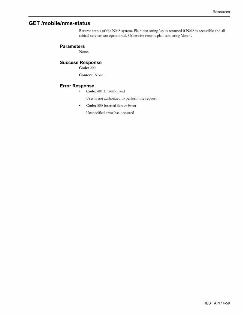
Resources
GET /mobile/nms-statusReturns status of the NMS system. Plain text string 'up' is returned if NMS is accessible and all critical services are operational. Otherwise returns plan text string 'down'.
ParametersNone.
Success ResponseCode: 200
Content: None.
Error Response• Code: 401 Unauthorized
User is not authorized to perform the request
• Code: 500 Internal Server Error
Unspecified error has occurred
REST API 14-59

Resources
PUT /trbl-rest/event/{id}/confirm-outageWill confirm open the device associated with a probable outage Event.
Parameters
Success Response• Code: 200
Content: None.
Error Response• Code: 401 Unauthorized
User is not authorized to perform the request
• Code: 500 Internal Server ErrorUnspecified error has occurred
Name Type Description
idrequired
path[integer] Event Idx
as-useroptional
query[string] User to do the API call as. The calling user must have “Allow as-user Parameter” mobile permission.
14-60 Oracle Utilities Network Management System Adapters Guide
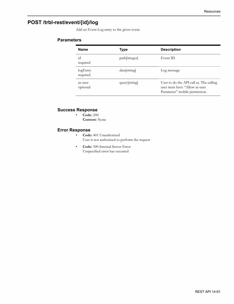
Resources
POST /trbl-rest/event/{id}/logAdd an Event Log entry to the given event.
Parameters
Success Response• Code: 200
Content: None
Error Response• Code: 401 Unauthorized
User is not authorized to perform the request
• Code: 500 Internal Server ErrorUnspecified error has occurred
Name Type Description
idrequired
path[integer] Event ID
logEntryrequired
data[string] Log message
as-useroptional
query[string] User to do the API call as. The calling user must have “Allow as-user Parameter” mobile permission.
REST API 14-61

Resources
POST /trbl-rest/event/{id}/log-onceAdd an Event Log entry to the given event; verify it has not already been added before.
Parameters
Success Response• Code: 200
Content: None.
Error Response• Code: 401 Unauthorized
User is not authorized to perform the request
• Code: 500 Internal Server ErrorUnspecified error has occurred
POST /trbl-rest/event/{id}/state-transitionRequest a state transition for the passed event.
Parameters
Success Response• Code: 200
Content: None.
Error Response• Code: 401 Unauthorized
User is not authorized to perform the request
Name Type Description
idrequired
path[integer] Event ID
logEntryrequired
data[string] Log message
as-useroptional
query[string] User to do the API call as. The calling user must have “Allow as-user Parameter” mobile permission.
Name Type Description
idrequired
path[integer] Event ID
actionrequired
data[string] The TE state action to be used to transition the event.
as-useroptional
query[string] User to do the API call as. The calling user must have “Allow as-user Parameter” mobile permission.
14-62 Oracle Utilities Network Management System Adapters Guide

Resources
• Code: 500 Internal Server ErrorUnspecified error has occurred
GET /trbl-rest/events/{id}/customersGet the customer information for the passed event index. This includes all custom fields from the CES_CUSTOMERS table.
Parameters
Success Response• Code: 200
Content: double array of customer information.
Error Response• Code: 401 Unauthorized
User is not authorized to perform the request
• Code: 500 Internal Server ErrorUnspecified error has occurred
Name Type Description
idrequired
path[integer] Event ID
REST API 14-63

Resources
POST /trbl-rest/user-log
Add an User Log entry to the given event.
Parameters
Success Response• Code: 200
Content: None.
Error Response• Code: 401 Unauthorized
User is not authorized to perform the request
• Code: 500 Internal Server ErrorUnspecified error has occurred
POST /trbl-rest/user-log-onceAdd an User Log entry to the given event; verify it has not already been added before.
Parameters
Success Response• Code: 200
Content: None.
Error Response• Code: 401 Unauthorized
User is not authorized to perform the request
• Code: 500 Internal Server ErrorUnspecified error has occurred
Name Type Description
logEntryrequired
data[string] Log message
Name Type Description
logEntryrequired
data[string] Log message
14-64 Oracle Utilities Network Management System Adapters Guide
Chapter 15Weather Data Adapter
This chapter includes the following topics:
• Adapter Overview
• Data Import Formats
• Running the Adapter
• Related Runtime and Configuration Tables
Adapter OverviewThe Weather Data adapter is responsible for pulling real-time and future forecast weather data for use by the DMS power flow analysis. The weather data is used within the DMS applications for two purposes.
1. To drive the load forecast used by the power flow analysis. The weather data will be used to set which load profile is used by the real-time and forecast power flow solutions.
2. The weather data will be archived in the NMS PF_DERMS_FORECAST_HISTORY database table such that it can be used by the Profile Adapter to determine a historical weather conditions for a particular weather zone. The Profile Adapter needs the historical data such that provided load profiles can be adjusted properly by the adapter depending on the recorded temperature.
Weather Data Adapter 15-1

Data Import Formats
Data Import FormatsThe Weather Data Adapter can import the weather data to either an NMS database or to a non-NMS database from any of the following sources:
1. Flat CSV Files
2. External Database Table
3. NOAA Weather Service
Flat CSV FilesThe adapter can import the data either from a single large CSV file or multiple smaller CSV files. However, they need to have a consistent format. Which means that they all should either have a header row or no header row and they all should have the columns in the same sequence. Projects should make sure that data is given in the same units as in the load profiles. The Adapter does not perform any unit conversions. However, while importing data to a NMS database, adapter can convert the data into profile keys if configured. For example, cloud coverage can be given as a string, 'Cloudy', 'Clear', 'Partially Cloudy' etc. or it can also be given as a solar potential index which varies between 0 and 1, or it can also be given in percentile. Power Flow can only process the indexes. If the data is given as a string or percentile, then adapter converts them to a profile key. In this case, project will have to set the rule_value_integer_4 to 1 in the corresponding 'distGenDefault' SRS-rule, and also have to provide the mapping between the values and the profile keys in the 'pf_weather_data_profile_map' table. If the data value is numerical then it will be mapped to the upper limit of that band. This kind of data conversion is not possible if importing data to a non-NMS database.
Input File FormatCSV files should have following four columns in any order:
• Zone: Name of the zone.
• Time: Date and time, in mm/dd/yyyy HH24:MI:SS format.
• Power Source: An integer representing temperature (-1), solar, and wind power source. This value should be consistent with the rule_value_integer_1 value of 'distGenDefault' SRS-rules.
• Value: Forecasted value.
ConfigurationThe adapter parameters are configured in the pf_weather_data_config database table, which should be present in the host database. The configuration table should have a row with parameter_name as 'source' and parameter_value_1 as 'CSV'. This configuration parameter tells the adapter the source of the weather data. The rest of the parameters are as follows:
• input_address: Environmental variable OPERATIONS_MODELS should be configured. This variable is set to the path to the directory that hosts the 'weather_data' directory. All input CSV files should be stored in 'weather_data' directory. The adapter creates two more directories in the weather_data directory. The first is 'log' which host the log files, and the second is 'parsed_csvs' which host all the csv files which have been processed by the adapter.
• headerPresent: This parameter should be set to 'yes' if CSV files have a header row present; otherwise, it should be set to 'no'.
• zone_column: It should be an integer specifying the column number of CSV file which contains the zone names. Column numbers start from 0 in CSVs
15-2 Oracle Utilities Network Management System Adapters Guide

Data Import Formats
• datetime_column: It should be an integer specifying the column number of CSV file which contains the date and time.
• power_source_column: It should be an integer specifying the column number of CSV file which contains power_source number
• value_column: It should be an integer specifying the column number of CSV file which contains the value for the corresponding power_source.
External Database TableThe adapter can import the data from an external database table. The connection with the external database should only be made through an Oracle Wallet. If the data is imported in an NMS database, the data conversion for solar and wind should be performed. The adapter does not perform data unit conversions while importing from a database table.
Input Table SchemaSimilar to CSV format, the source database table should have the following fields:
• Zone: Name of the zone
• Time: Date and time
• Power Source: an integer representing temperature (-1), solar, and wind power source. This value should be consistent with the rule_value_integer_1 value of 'distGenDefault' SRS-rules.
• Value: forecast-ed value
ConfigurationThe adapter parameters are configured in the pf_weather_data_config database table, which should be present in the host database. The configuration table should have a row with parameter_name as 'source' and parameter_value_1 as 'DB'. This configuration parameter tells the adapter the source of the weather data. The rest of the parameters are as follows:
• sourceDBServer: This parameter needs three values:
• parameter_value_1: Name of the server machine.
• parameter_value_2: Port number on which database service is running.
• parameter_value_3: Database service name.
• sourceDBTableName: The name of the source database table.
• zone_column: The name of the database table field that contains the zone names.
• datetime_column: The name of the database table field that contains the date and time.
• power_source_column: name of the database table field which contains power_source number.
• value_column: name of the database table field which contains the value for the corresponding power_source.
Weather Data Adapter 15-3

Data Import Formats
NOAA Weather ServiceThe adapter is capable of capturing 1 hour, 24 hour, and 7 days of hourly data from NOAA. The adapter pulls the temperature, wind speed and cloud coverage data from the Internet. NOAA provides the data in 3 hour intervals. This adapter automatically interpolates the data according to the FLM granularity provided by SRS rule 'FLM Custom Forecasting' in rule_value_integer_1.
Since the adapter is pulling data from the NOAA weather feeder, this adapter is only applicable to US customers. The adapter works by reading the configured weather zones in the local PF_WEATHER_ZONE database table. The associated latitude and longitude is then used to gather the associated weather data. Therefore, the host database must have this table for the adapter to work. The adapter parses the data and places it in the PF_WEATHER_ZONE_FORECAST database table.
ConfigurationThe adapter parameters are configured in the pf_weather_data_config database table, which should be present in the host database. The configuration table should have a row with parameter_name as ‘source’ and parameter_value_1 as ‘NOAA’.
To utilize the adapter the following configuration items will need to be completed.
1. proxy: If a proxy is needed to get out of the internal network, the following rule will need to be configured with proxy details in local database table PF_WEATHER_DATA_CONFIG. If no proxy exists this rule does not need to be configured.
Example
INSERT INTO pf_weather_data_config (parameter_name,parameter_value_1, parameter_value_2, parameter_value_3) VALUES ('proxy', 'http', 'www-proxy.us.oracle.com', '80');
2. solar_power_id: It should be consistent with the corresponding 'distGenDefault' SRS-rule'.
3. wind_power_id: It should also be consistent with the corresponding 'distGenDefault' SRS-rule'.
4. temperature_unit: F or C. By default, NOAA gives temperature data in Fahrenheit. However, the adapter can convert the temperatures to Celsius if configured. This unit should be consistent with the unit used in the load profiles.
5. wind_speed_unit: By default, NOAA gives the wind speed in knots. However, adapter converts it to miles per hour (mph) or kilometer per hour (kph) as configured. This unit should be consistent with the unit used in the load profiles.
6. noaa_conn_reattempts: Sometimes the adapter fails to connect with NOAA or NOAA returns inconsistent data. In these cases, this option can be configured to automatically make multiple attempts to connect with the NOAA service. The maximum number of reattempts and the delay between connection attempts are configured using parameter value 1 and parameter value 2, respectively.
15-4 Oracle Utilities Network Management System Adapters Guide

Running the Adapter
Load FrequencyCustomers wishing to use the NMS weather adapter to pull NOAA weather service data need to configure the adapter to be invoked on a cron job. Setting up a cron job allows customers to decide the frequency and amount of data to pull at any given time. The adapter can be called for the following forecast modes.
1. Weekly - The adapter will obtain 7 days worth of weather forecast data
2. Hourly - The adapter will obtain weather data for the next 24 hours
3. Current - The adapter will obtain the current weather data if it is run without either the -hourly or -weekly options.
For example, a customer may want to update the weekly forecast daily, the hourly forecast twice a day, and gather the current weather data each hour. Another example would be to run the weekly forecast daily and just run the hourly forecast once in the morning.
Running the AdapterThe weather data adapter can be run with the following command line options:
python product_weatherDataAdapter.py [-v] [-debug] [-hourly] [-weekly] [-exdb]
Sometimes the adapter fails to connect with NOAA or NOAA returns inconsistent data. In these cases, the noaa_conn_reattempts option can be configured to automatically make multiple attempts to connect with the NOAA service. For details, see the preceding configuration section.
Option Description
-v Turn on verbose output.
-debug Turn on debug to assist with adapter issues. If debug is turned on, it will turn on verbose output.
-hourly to pull hourly data from NOAA
-weekly to pull weekly data from NOAA
-exdb must run with this option if importing data to a non-NMS database
Weather Data Adapter 15-5
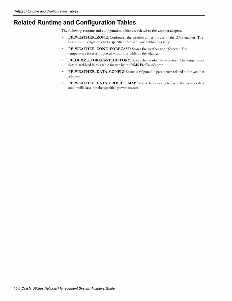
Related Runtime and Configuration Tables
Related Runtime and Configuration TablesThe following runtime and configuration tables are related to the weather adapter.
• PF_WEATHER_ZONE: Configures the weather zones for use by the DMS analysis. The latitude and longitude can be specified for each zone within this table.
• PF_WEATHER_ZONE_FORECAST: Stores the weather zone forecast. The temperature forecast is placed within this table by the adapter.
• PF_DERMS_FORECAST_HISTORY: Stores the weather zone history. The temperature data is archived in this table for use by the NMS Profile Adapter.
• PF_WEATHER_DATA_CONFIG: Stores configuration parameters related to the weather adapter.
• PF_WEATHER_DATA_PROFILE_MAP: Stores the mapping between the weather data and profile keys for the specified power sources.
15-6 Oracle Utilities Network Management System Adapters Guide
Chapter 16DERMS Adapter
This chapter includes the following topics:
• Overview
• Configuration
• Running the Adapter
• Database Tables
• Log Files
OverviewThe Oracle Utilities NMS Distribution Management System uses DERMS forecast updates of various fuel source types (such as wind, solar/photovoltaic, diesel, etc.) for power flow analysis. The forecast updates are loaded into the NMS PF_DER_FORECAST, PF_DER_DEMAND_RESPONSE_FORECAST, and PF_WEATHER_ZONE_FORECAST database tables. These tables may be populated by any mechanism suitable for the project’s business processes and data sources. An NMS script, product_DERMSAdapter.py, can be used to load the tables with data from a CSV file or an RDBMS table.
ConfigurationThe script expects the CSV file at the path $OPERATIONS_MODELS/derms_forecasts. The processed CSV files are moved to $OPERATIONS_MODELS/derms_forecasts/parsed_CSVs sub directory and the errors are logged at $OPERATIONS_MODELS/derms_forecasts/log directory. The CSV file format is specified in the PF_DERMS_ADAPTER_CONFIG database table. This includes configuring information like number of columns, column positions and whether header present or not.
If the input is an RDBMS table, then the forecast updates are expected in a database table. If the adapter is running on enterprise service network, then the forecast updates are expected in the DERMS_FORECAST_UPDATES table. If the adapter is running on operational service network, then the forecast updates are expected in the PF_DERMS_FORECAST_UPDATES table.
DERMS Adapter 16-1

Configuration
PF_DERMS_ADAPTER_CONFIG
The following parameters are configured in the in the table PF_DERMS_ADAPTER_CONFIG:
Name Data Type Description
parameter_name VARCHAR2(32) The name of the parameter. Required.
parameter_value_1 VARCHAR2(64) Required parameter value.
parameter_value_2 VARCHAR2(64) Optional parameter value.
parameter_value_3 VARCHAR2(64) Optional parameter value.
Parameter Description
sourceDBServiceName Sets the database service name, server name, and port details for the forecast updates table.
• parameter_value_1: server name. The default value is DB.
• parameter_value_2: port number.
• parameter_value_3: database service name.
operationalService Sets whether the adapter is running on the operational service network or the enterprise service network.
• parameter_value_1: Yes | No
• Yes: operational service network
• No: the enterprise service network
useSqlLoader Sets whether to use SQL Loader or NMS Import to load the data into NMS tables.
• parameter_value_1: Yes | No
• Yes: SQL Loader
• No: NMS Import or other process
forecastDir The directory containing the forecast CSV file.
numDataCol Define rule to specify the number of columns in raw CSV
16-2 Oracle Utilities Network Management System Adapters Guide
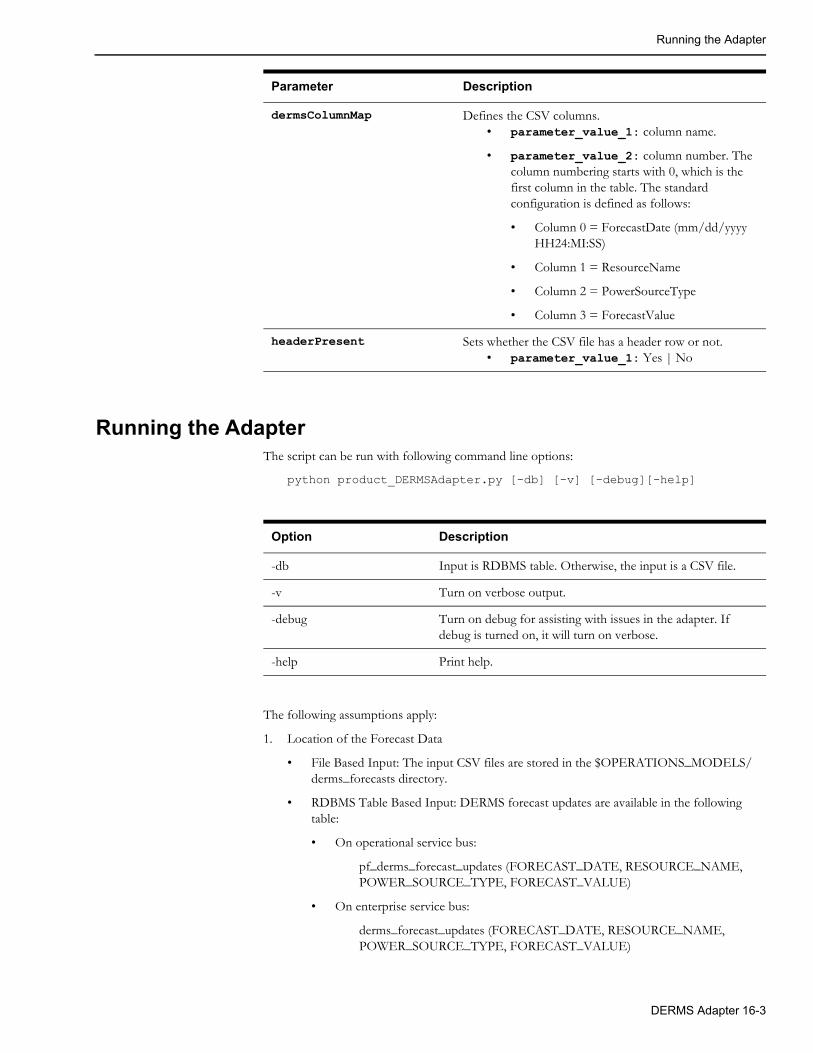
Running the Adapter
Running the AdapterThe script can be run with following command line options:
python product_DERMSAdapter.py [-db] [-v] [-debug][-help]
The following assumptions apply:
1. Location of the Forecast Data
• File Based Input: The input CSV files are stored in the $OPERATIONS_MODELS/derms_forecasts directory.
• RDBMS Table Based Input: DERMS forecast updates are available in the following table:
• On operational service bus:
pf_derms_forecast_updates (FORECAST_DATE, RESOURCE_NAME, POWER_SOURCE_TYPE, FORECAST_VALUE)
• On enterprise service bus:
derms_forecast_updates (FORECAST_DATE, RESOURCE_NAME, POWER_SOURCE_TYPE, FORECAST_VALUE)
dermsColumnMap Defines the CSV columns.• parameter_value_1: column name.
• parameter_value_2: column number. The column numbering starts with 0, which is the first column in the table. The standard configuration is defined as follows:
• Column 0 = ForecastDate (mm/dd/yyyy HH24:MI:SS)
• Column 1 = ResourceName
• Column 2 = PowerSourceType
• Column 3 = ForecastValue
headerPresent Sets whether the CSV file has a header row or not. • parameter_value_1: Yes | No
Parameter Description
Option Description
-db Input is RDBMS table. Otherwise, the input is a CSV file.
-v Turn on verbose output.
-debug Turn on debug for assisting with issues in the adapter. If debug is turned on, it will turn on verbose.
-help Print help.
DERMS Adapter 16-3
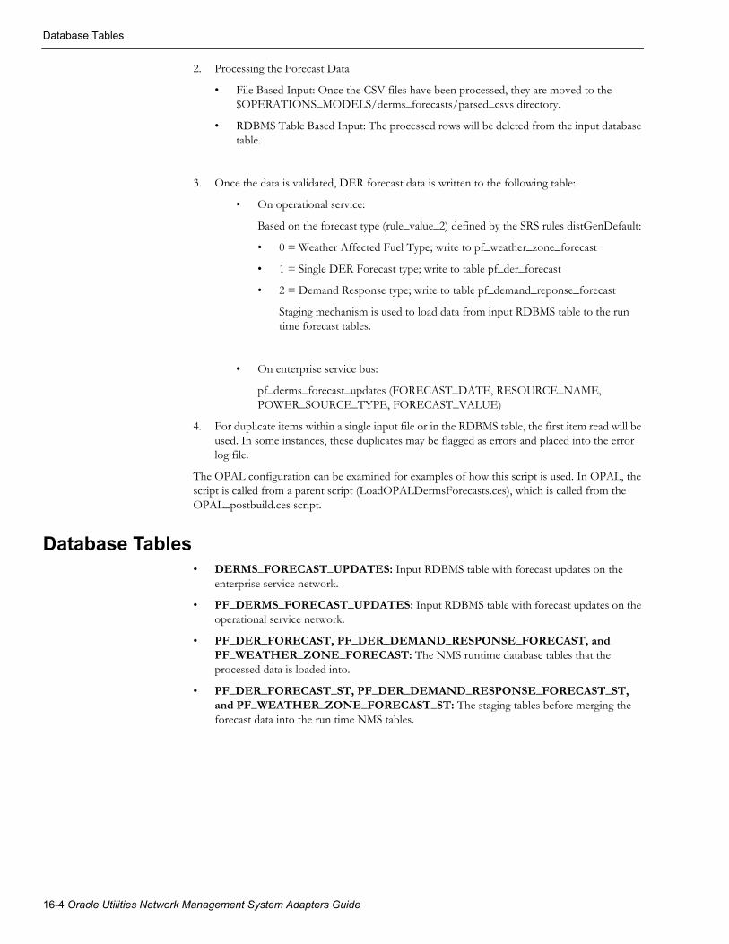
Database Tables
2. Processing the Forecast Data
• File Based Input: Once the CSV files have been processed, they are moved to the $OPERATIONS_MODELS/derms_forecasts/parsed_csvs directory.
• RDBMS Table Based Input: The processed rows will be deleted from the input database table.
3. Once the data is validated, DER forecast data is written to the following table:
• On operational service:
Based on the forecast type (rule_value_2) defined by the SRS rules distGenDefault:
• 0 = Weather Affected Fuel Type; write to pf_weather_zone_forecast
• 1 = Single DER Forecast type; write to table pf_der_forecast
• 2 = Demand Response type; write to table pf_demand_reponse_forecast
Staging mechanism is used to load data from input RDBMS table to the run time forecast tables.
• On enterprise service bus:
pf_derms_forecast_updates (FORECAST_DATE, RESOURCE_NAME, POWER_SOURCE_TYPE, FORECAST_VALUE)
4. For duplicate items within a single input file or in the RDBMS table, the first item read will be used. In some instances, these duplicates may be flagged as errors and placed into the error log file.
The OPAL configuration can be examined for examples of how this script is used. In OPAL, the script is called from a parent script (LoadOPALDermsForecasts.ces), which is called from the OPAL_postbuild.ces script.
Database Tables• DERMS_FORECAST_UPDATES: Input RDBMS table with forecast updates on the
enterprise service network.
• PF_DERMS_FORECAST_UPDATES: Input RDBMS table with forecast updates on the operational service network.
• PF_DER_FORECAST, PF_DER_DEMAND_RESPONSE_FORECAST, and PF_WEATHER_ZONE_FORECAST: The NMS runtime database tables that the processed data is loaded into.
• PF_DER_FORECAST_ST, PF_DER_DEMAND_RESPONSE_FORECAST_ST, and PF_WEATHER_ZONE_FORECAST_ST: The staging tables before merging the forecast data into the run time NMS tables.
16-4 Oracle Utilities Network Management System Adapters Guide

Log Files
Log FilesLog files are placed in the $OPERATIONS_MODELS/derms_forecasts/log directory. When the adapter is executed, old log files will be moved to the $OPERATIONS_MODELS/derms_forecasts/logs/old_log directory.
Log files are generated with following name format:
• DERMS_Data_Errors_YYYYMMDD_HHMMSS.log: Contains any invalid data rows along with an error code from the below list.
• DERMS-001: Too many fields.
• DERMS-002: Too few fields.
• DERMS-003: Invalid forecast date.
• DERMS-004: Invalid hour value should be integer.
• DERMS-005: Invalid hour value should be 0-23.
• DERMS-006: Duplicate hourly record found for day type/hour value.
• DERMS-007: Invalid Resource Name. The weather zone, DER, or Demand Response Group associated to the forecast could not be located in the configuration.
• DERMS-008: Invalid forecast value. It should be a float value.
• DERMS-009: Invalid number of hourly records.
DERMS Adapter 16-5

Log Files
16-6 Oracle Utilities Network Management System Adapters Guide

Chapter 17Profile Adapter
This chapter includes the following topics:
• Adapter Overview
• PV Profile Creation
• Load Profile Creation
• SRS Rule Configuration
• Load Profile File Format
• Error Handling
Adapter OverviewThe NMS Profile adapter is responsible for two main tasks:
1. Create Photovoltaic (PV) profile curves based on a utilities location and the time of year.
2. Create and adjust temperature based load profiles for use in the real-time power flow analysis and forecasting.
PV Profile CreationIf required the NMS Profile adapter can be configured to create PV profiles based on the time of year and the utilities location. These profiles are used within the NMS power flow analysis to simulate time of day PV output based on varying ranges of cloud cover and help provide more accurate power flow solutions. The power flow analysis holds weather forecast data for customer configured weather zones, this forecast data drives which PV profiles are used for each weather zone. For example if a customer had two weather zones “Coastal” and “Mountain”, If it was predicted to be “Sunny” from 9am-1pm then “Cloudy” from 1pm-6pm in the “Coastal” zone the analysis would use the proper output for each hour using snippets from both profiles. For solutions from 9am-1pm the analysis would use the “Sunny” profile then switch to using the “Cloudy” profile for solutions from 1pm-6pm. This same methodology would be applied to the “Mountain” zone power flow solutions using its own unique weather forecast. It is up to the utility to determine the granularity at which they require weather zones some may take a broad approach based on geographic region others may chose something more granular such as zip code.
The curves generated by the adapter reflect a normalized output and within the power flow analysis will be applied against the device specific kW output. The number of PV generation curves that represent varying levels of cloud cover is configurable; some customers may require more granularity for accurate results. For example one customer may deem that only three profiles are needed to represent Sunny, Partly, and Cloudy. Another customer may configure this with 10 different levels of cloud cover for more granularity. During PV profile generation the adapter first
Profile Adapter 17-1

SRS Rule Configuration
creates a max output curve based on the location and time of year. The adapter then creates the various profiles based on customer provided scale factors to represent output based on different levels of cloud cover. For example a customer may say Sunny = 100%, Partly Cloudy=70%, Cloudy = 40%, etc.
Load Profile CreationThe main purpose of the NMS Profile adapter is to create and adjust temperature based load profiles. These profiles are used within the NMS power flow analysis to simulate time of day load behavior for a particular temperature band. Similar to PV profiles the load profile curve used at a particular time of the day will be dependent upon the weather zone forecast. As the temperature increases or decreases in each zone the power flow analysis will continually switch between different temperature based profiles to simulate load as accurately as possible.
The source of data for the load profiles is expected to be an AMI/MDM system that has aggregated the meter data up to the service transformer level. The data should be provided with an associated date/time. During the load the adapter will determine if a profile already exists for the transformer in which case the data will be used to adjust the existing profile or create an entirely new record if no data yet exists. The adapter will use the date/time provide to cross reference what the temperature was for that hour such that each hour worth of data can be utilized in the appropriate profile. If a new sample is received for Monday at 9am for profile Sample_xfmr_1 at 65F the adapter will need to determine if this sample already exists. If a sample already exists the adapter must look at the number of samples that have been taken into account and calculate a rolling average based on that. Each row in the pf_load_interval_data will consist of a profile id, day type, profile values, and temperature or temp band for which the profile is a part of. When PFService is finding a profile to use for each day it will essentially be grabbing snippets from each row within this table, since the temp generally doesn’t stay constant all day. For example it may use hours 0-5 from the 60-69F profile then use hours 6-12 from the 70-79F profile, etc. For profiles that are used in study mode only (e.g. peak) the profile will be loaded into the database as a direct replacement, no averaging will be conducted. For study only profiles a blank date can be provided.
During an initial implementation no data will yet exist for load profiles so it may take some time to start building up accurate profiles. After each load however the profiles will adapt and change as needed based on new data.
Note: If a customer does not wish to use temperature based profiles, but still wishes to use the adapter to generate load profiles, the SRS rule "USE_TEMP_PROFILES" can be set to a value of "no". In this situation, it will be expected that the customer sets up the PF_TEMPERATURE_BANDS table with a single temperature band that encompass the entire range of the temperatures the service territory may encounter (for example, -20F to 110F). This all encompassing band should be keyed with an index of zero. When the adapter loads the profiles, all values will be placed in the temperature band indexed with a value of zero. When the power flow attempts to find the profile to use in the analysis, it will always use the temperature band keyed with zero when the "USE_TEMP_PROFILES" SRS rule is set to "no".
SRS Rule ConfigurationA number of SRS rules exist that configure the behavior of the Profile adapter to meet different customer business requirements. To view the Load Profiles SRS Rules, open the Configuration Assistant’s Event Management Rules tab, expand the DMS Application Rules navigation tree, and then either select or expand the Load Profile Rules tree.
17-2 Oracle Utilities Network Management System Adapters Guide

Running the Adapter
Running the AdapterThe adapter can be run with following command line options:
ProfileAdapter [-adjDefaults] [-dbname <dbname>] [-clean] [-partial] [-createPvOnly] [-debug number] [-verbose]
Option Description
-adjDefaults This option will force the adapter to adjust any default data associated to a load profile. When beginning to use temperature based profiles, it may take a significant amount of time to obtain all of the sampled data for different day type, temperature, and hour combinations. By running with this option, the adapter will adjust the defaulted data associated with each transformer profile to be more in line with actual data received. The processing will find the average scale factor for the different temperature bands that have received actual data for each hour. That average will then be applied to any temperature band for the same corresponding hour that has not yet received actual data and is still using a default. This helps to fill in any discrepancies where actual data is smaller or larger than the defaults. It is recommended this procedure be run once or twice per month to manage the defaulted data. This processing can be run standalone, and CSV files do not need to be present in the staging directory.
-clean This option will clean all non default load profiles and load profile history before loading a new CSV file. The adapter will first truncate tables pf_loads_profile_samples and pf_loads_profile_override. It will then prune all non distributed generation and default load profiles from table pf_load_interval_data. After the tables are cleaned up it will then process the new CSV file which essentially does a fresh load.
-dbname <dbname> This option allows projects to use a separate DBService instance to handle all database requests from the adapter. To use this parameter, the LPDBService will need to be setup in the system.dat file. The value provided for <dbname> will be the name provided in the system.dat for the -service parameter for LPDBService. It is recommend that customers run with this parameter.
-partial Used when doing a partial load of profiles. (for example, the entire data set is not being loaded).
-createPvOnly Force the adapter to create PV profiles only, non processing of load profiles will be conducted.
-debug number Required debug level (0-3).
-verbose Turn on verbose output for adapter.
Profile Adapter 17-3

Running the Adapter
The following assumptions apply:
1. Location of the Load Profile Data
• The load profile CSV files should be placed in the directory configured by the PA_ProfileDir SRS rule.
2. Processing the Load Profile Data
• Once the CSV files have been processed by the adapter, they will be moved to the parsed_csvs subdirectory in the directory pointed to by SRS rule PA_ProfileDir
3. Once the data is validated, the load profile data will be written to the following tables:
• PF_LOAD_INTERVAL_DATA: Stores the load profile curves.
• PF_LOADS_PROFILE_SAMPLES: Stores the number of time each data points has been sampled.
• PF_LOADS_PROFILE_OVERRIDE: Manages a record of which loads have device specific load profiles.
4. All Load Profile Adapter specific logs will be placed in a subdirectory labeled logs of the directory pointed to by the PA_ProfileDir SRS rule.
17-4 Oracle Utilities Network Management System Adapters Guide

Load Profile File Format
Load Profile File FormatProfiles are to be loaded on customer specified maintenance interval (Product recommends doing this weekly or bi-weekly to reduce the CSV file size). Profiles will need to be aggregated by the customer from meter data to service transformers that are represented as load points within the NMS. The data provided for each service transformer will represent a profile for a specific date, for study mode only profiles (for example, Peak, Seasonal Peak) a blank date can be provided.
The transformer load profile data is provided as a comma-separated file with a comma separated header.
The expected (but not required) header is:
Date,TransformerName,TransformerAlternateName,FeederName,DayType,Hour,KW,KVAR,Temperature
File Characteristics Values
Fixed length fields? N
Delimiter Comma
Header style Comma separated, optional
Footer Style No
No of files Can be feeder based or 1 file for entire service territory
S. No Field Name Length Mandatory Data type
<Order of the element in the record>
<Name of the field>
<Field Length>
<Optional (N) or Mandatory (Y)>[Note #]
<Data type as per XSD standards>
1 Date (MM/DD/YY)
8 Y [1] Date
2 TransformerName
32 Y String
3 TransformerAlternateName
32 N [2] String
4 FeederName 32 Y String
5 DayType 12 Y Enumerated string (weekday, weekend, peak) or associated Integer key that corresponds to the DayType
6 Hour 2 Y Integer (max 23)
7 KW N/A Y Floating point
8 KVAR N/A Y [3] Floating point
9 Temperature N/A N [4] Floating point, can be provided in either Fahrenheit or Celsius
Profile Adapter 17-5

Error Handling
Note 1: Date can be left blank is profile is for study mode only (e.g., Peak, Seasonal Peak, etc).
Note 2: Optional fields may be omitted from the file, resulting in two consecutive commas.
Note 3: If KVAR is not measured, it can be calculated from KW with a default power factor.
Note 4: The temperature field is optional. A utility may provided temperature data for location, date, and time. If no temperature data is provided the adapter will use historical data stored in the NMS database. If this data is going to be omitted please leave the temperature field null.
Error HandlingThe ingestion process for load profiles will perform error validation on the incoming data. It will create two error validation files and one timing file, which will be located in a subdirectory of the project configurable data location directory:
1. Invalid transformers (LP_Invalid_Transformers_YYYYMMDD_HHMMSS.log)
This file will contain a list of the transformer/feeder combinations that cannot be located within the NMS model.
2. Invalid data (LP_Data_Errors_YYYYMMDD_HHMMSS.log)
This file will contain any invalid data rows along with an error code from the table below.
3. Timing (LP_Timing_YYYYMMDD_HHMMSS.log)
This file will provide timing information related to different processes occurring during the load of profile data. For example, how long it takes to read the CSV files, how long it takes to write profiles to the database, and so on.
Error Code Error Description Notes
LP-001 Too many fields Expect 8 fields, 7 commas
LP-002 Too few fields Expect 8 fields, 7 commas
LP-003 Invalid day type The day type specified is not valid
LP-004 Invalid hour value Should be integer type
LP-005 Invalid hour value Should be 0 through 23
LP-006 Invalid KW value Should be floating type
LP-007 Invalid KVAR value Should be floating type
LP-008 Duplicate Record Duplicated hourly record found
LP-009 Invalid KVA rating or utilization factor
These values should be present in table pf_loads
LP-010 Transformer loading exceeds the rating based on specified threshold.
The threshold can be configured in the SRS rules, currently set to 200%
LP-011 Invalid Weather Zone The weather zone associated to the load could not be located in the configuration.
17-6 Oracle Utilities Network Management System Adapters Guide

Error Handling
LP-012 Invalid temperature value should be floating type.
Should be floating type.
LP-013 Load is mapped to a zone but the zone does not appear to be a valid weather zone.
Validate this zone associated to the load is present in table PF_WEATHER_ZONE and forecast data is present in table PF_WEATHER_ZONE_FORECAST.
NM-001 Dist Gen data could not be located
Dist Gen information could not be located for a dist gen associated with a net metered profile.
NM-002 Dist Gen has an invalid power source
Power source is invalid for a dist gen associated with a net metered profile.
NM-003 Dist Gen Invalid Weather Zone Weather zone is invalid for a dist gen associated with a net metered profile.
NM-004 Dist Gen Profile is invalid The profile associated to the dist gen could not be located. This is needed to perform net metered profile processing.
NM-005 Dist Gen output exceeds the connected transformers rating based on a specified threshold.
This rule uses the same SRS rule as used for LP-010 and can be configured in the SRS rules. The NM-005 error is looking purely at Dist Gen output in comparison to the rating of the transformer excluding any loading information.
Error Code Error Description Notes
Profile Adapter 17-7

Error Handling
17-8 Oracle Utilities Network Management System Adapters Guide