Embed Size (px)
Citation preview

Real Wireless Ltd PO Box 2218 Pulborough t +44 207 117 8514 West Sussex f +44 808 280 0142 RH20 4XB e [email protected] United Kingdom www.realwireless.biz
Options for Improving In-Building Mobile Coverage
Appendices to final report
Issued to: Ofcom Issue date: 18 April 2013 Version: 1.2
Self-provided Wi-Fi
Carrier Wi-Fi UMA
Intelligent Repeaters
Femtocells Picocells
DAS
Consumer Repeaters

Options for Improving In-Building Mobile Coverage Issue date: 18 April 2013 Version: 1.2
Version Control
Item Description
Source Real Wireless
Client Ofcom
Report title Options for Improving In-Building Mobile Coverage
Sub title Appendices to final report
Issue date 18 April 2013
Version Date Comment
1.0 14/03/2013 1st
issue to Ofcom
1.1 17/04/2013 Revised in line with feedback on v1.0 from Ofcom for internal review
1.2 18/04/2013 2nd
issue to Ofcom

Copyright ©2013 Real Wireless Limited. All rights reserved. Registered in England & Wales No. 6016945
About Real Wireless
Real Wireless is a leading independent wireless consultancy, based in the U.K. and
working internationally for enterprises, vendors, operators and regulators –
indeed any organization which is serious about getting the best from wireless to
the benefit of their business.
We seek to demystify wireless and help our customers get the best from it, by
understanding their business needs and using our deep knowledge of wireless to
create an effective wireless strategy, implementation plan and management
process.
We are experts in radio propagation, international spectrum regulation, wireless
infrastructures, and much more besides. We have experience working at senior
levels in vendors, operators, regulators and academia.
We have specific experience in LTE, UMTS, HSPA, Wi-Fi, WiMAX, DAB, DTT, GSM,
TETRA – and many more.
For details contact us at: [email protected]
Tap into our news and views at: realwireless.biz/blog
Stay in touch via our tweets at twitter.com/real_wireless

Options for Improving In-Building Mobile Coverage Issue date: 18 April 2013 Version: 1.2

Options for Improving In-Building Mobile Coverage Issue date: 18 April 2013 Version: 1.2
Contents
1. Introduction........................................................................................... 5
1.1 Scope of these appendices ............................................................................ 5
1.2 Structure of these appendices ...................................................................... 5
2. Appendix A – Requirements across consumer groups in more detail ....... 7
2.1 The home user ............................................................................................... 7
2.2 Business users .............................................................................................. 10
2.2.1 Small office / SME users .............................................................................. 10
2.2.2 Large multi-storey office users .................................................................... 11
2.3 Users in public buildings and complexes ..................................................... 13
2.4 Summary of requirements and priorities across user groups and deployment types ....................................................................................................... 14
3. Appendix B – Detailed description of our quantitative analysis of the size of the in-building problem and factors impacting this in the future ..................... 16
3.1 Limitations on our analysis .......................................................................... 16
3.2 Assumptions, inputs and methodology ....................................................... 16
3.3 Current and future indoor coverage trends based on network roll out and spectrum availability ................................................................................................... 19
3.4 Sensitivity of indoor coverage to changes in building regulations and reductions in mobile device sensitivity ...................................................................... 20
3.5 Sensitivity of indoor coverage to changes in user expectations of mobile services 23
3.6 Our quantitative analysis of the potential size of the in-building problem 25
3.7 Summary of key findings ............................................................................. 28
3.7.1 Estimates of current and future indoor coverage based on network roll out and spectrum availability ............................................................................................ 29
3.7.2 Factors impacting indoor coverage levels ................................................... 29
3.7.3 The potential size of the in-building problem ............................................. 30
4. Appendix C – Detailed discussion of outside-in solutions for in-building service issues ..................................................................................................... 32
4.1 Macrocell enhancements ............................................................................ 32
4.1.1 Consumer proposition ................................................................................. 33
4.1.2 Concept in more detail ................................................................................ 34
4.1.3 Standards ..................................................................................................... 39
4.1.4 Industry ecosystem ...................................................................................... 40
4.1.5 Current availability and future evolution .................................................... 40
4.1.6 Environmental impact ................................................................................. 41
4.1.7 Operator deployment views ........................................................................ 41

Options for Improving In-Building Mobile Coverage Issue date: 18 April 2013 Version: 1.2
4.1.8 Assessment against Ofcom’s criteria ........................................................... 44
4.2 Outdoor small cells ...................................................................................... 45
4.2.1 Consumer proposition ................................................................................. 46
4.2.2 Concept in more detail ................................................................................ 47
4.2.3 Standards ..................................................................................................... 48
4.2.4 Industry ecosystem ...................................................................................... 49
4.2.5 Current availability and future evolution .................................................... 50
4.2.6 Environmental impact ................................................................................. 51
4.2.7 Operator deployment views ........................................................................ 51
4.2.8 Assessment against Ofcom’s criteria ........................................................... 53
5. Appendix D – Detailed discussion of dedicated in-building solutions currently available – Wi-Fi .................................................................................. 55
5.1 Self-provided Wi-Fi ...................................................................................... 55
5.1.1 Consumer proposition ................................................................................. 55
5.1.2 Concept in more detail ................................................................................ 57
5.1.3 Standards ..................................................................................................... 58
5.1.4 Industry ecosystem ...................................................................................... 60
5.1.5 Current availability and future evolution .................................................... 62
5.1.6 Environmental impact ................................................................................. 64
5.1.7 Operator deployment views ........................................................................ 65
5.1.8 Assessment against Ofcom’s criteria ........................................................... 65
5.2 Carrier Wi-Fi ................................................................................................. 66
5.2.1 Consumer proposition ................................................................................. 67
5.2.2 Concept in more detail ................................................................................ 69
5.2.3 Standards ..................................................................................................... 70
5.2.4 Industry ecosystem ...................................................................................... 75
5.2.5 Current availability and future evolution .................................................... 77
5.2.6 Environmental impact ................................................................................. 81
5.2.7 Operator deployment views ........................................................................ 81
5.2.8 Assessment against Ofcom’s criteria ........................................................... 83
5.3 UMA/GAN .................................................................................................... 84
5.3.1 Consumer proposition ................................................................................. 84
5.3.2 Concept in more detail ................................................................................ 85
5.3.3 Standards ..................................................................................................... 86
5.3.4 Industry ecosystem ...................................................................................... 87
5.3.5 Current availability and future evolution .................................................... 88
5.3.6 Environmental impact ................................................................................. 89
5.3.7 Operator deployment views ........................................................................ 89

Options for Improving In-Building Mobile Coverage Issue date: 18 April 2013 Version: 1.2
5.3.8 Assessment against Ofcom’s criteria ........................................................... 90
6. Appendix E – Detailed discussion of dedicated in-building solutions currently available – Cellular small cell related solutions .................................... 91
6.1 Femtocells .................................................................................................... 91
6.1.1 Consumer proposition ................................................................................. 92
6.1.2 Concept in more detail ................................................................................ 93
6.1.3 Standards ..................................................................................................... 94
6.1.4 Industry ecosystem ...................................................................................... 97
6.1.5 Current availability and future evolution .................................................... 98
6.1.6 Environmental impact ............................................................................... 100
6.1.7 Operator deployment views ...................................................................... 100
6.1.8 Assessment against Ofcom’s criteria ......................................................... 102
6.2 Picocells ..................................................................................................... 104
6.2.1 Consumer proposition ............................................................................... 104
6.2.2 Concept in more detail .............................................................................. 106
6.2.3 Standards ................................................................................................... 107
6.2.4 Industry ecosystem .................................................................................... 107
6.2.5 Current availability and future evolution .................................................. 109
6.2.6 Environmental impact ............................................................................... 110
6.2.7 Operator deployment views ...................................................................... 110
6.2.8 Assessment against Ofcom’s criteria ......................................................... 111
7. Appendix F - Detailed discussion of dedicated in-building solutions currently available – Traditional in-building solutions and their evolution .........114
7.1 Repeaters (Operator deployed, consumer repeater and intelligent repeaters) ................................................................................................................. 114
7.1.1 Consumer proposition ............................................................................... 115
7.1.2 Concept in more detail .............................................................................. 117
7.1.3 Standards ................................................................................................... 121
7.1.4 Industry ecosystem .................................................................................... 122
7.1.5 Current availability and future evolution .................................................. 123
7.1.6 Environmental impact ............................................................................... 124
7.1.7 Operator deployment views ...................................................................... 124
7.1.8 Assessment against Ofcom’s criteria ......................................................... 126
7.2 Distributed Antenna Systems (DASs) ........................................................ 127
7.2.1 Consumer proposition ............................................................................... 127
7.2.2 Concept in more detail .............................................................................. 128
7.2.3 Standards ................................................................................................... 131
7.2.4 Industry ecosystem .................................................................................... 133
7.2.5 Current availability and future evolution .................................................. 134

Options for Improving In-Building Mobile Coverage Issue date: 18 April 2013 Version: 1.2
7.2.6 Environmental impact ............................................................................... 136
7.2.7 Operator deployment views ...................................................................... 136
7.2.8 Assessment against Ofcom’s criteria ......................................................... 138
8. Appendix G – Detail of stakeholder engagement undertaken for this study and summary of key points raised ...........................................................140
8.1 Overview of the stakeholder engagement process .................................. 140
8.2 Summary of Wi-Fi stakeholders ................................................................ 141
8.3 Summary of small cells, femtocells and picocells stakeholders ................ 144
8.4 Summary of mobile operators stakeholders ............................................. 151
8.5 Summary of DAS stakeholders .................................................................. 156
8.6 Summary of repeater vendors .................................................................. 161
References ........................................................................................................166

5
Options for Improving In-Building Mobile Coverage Issue date: 18 April 2013 Version: 1.2
1. Introduction
1.1 Scope of these appendices
This document forms the supporting Appendices for the final report on a study for Ofcom by Real Wireless into “Options for Improving In-building Mobile Coverage”.
1.2 Structure of these appendices
These appendices are structured as follows:
Appendix A describes the different type of indoor user groups and building types considered in the study, the requirements of each of these and their priorities across these requirements.
Appendix B describes the quantitative analysis undertaken in this study to understand the size of the in-building coverage problem in the UK today and the impact of various factors on this in the future.
Appendix C gives a detailed description of outside-in solutions to addressing poor in-building service levels such as macrocell enhancements, new site builds and the deployment of outdoor small cells.
Appendices D, E and F give a detailed description of the dedicated in-building solutions available to improve in-building service levels today which we have categorised into: o Wi-Fi related solutions covering self-provided Wi-Fi, carrier Wi-Fi and
UMA o Cellular small cell solutions covering femtocells and picocells o Traditional dedicated in-building solutions and their evolutions covering
consumer repeaters (both traditional and new intelligent repeaters), operator deployed repeaters, distributed antenna systems and distributed basestation solutions.
Appendix G details the stakeholder engagement process undertaken in this study and the key views captured from this
In the cases of Appendices C, D, E and F for each technology discussed we:
Provide a consumer view of the technology and assess it against the user groups discussed in appendix A.
Provide a detailed description of the technology against each of Ofcom’s study requirements of: o Current status, take up and availability o Openness o Authentication and handover o Security o Impact on macro o Uplink and downlink constraints o Current and future spectrum o Environmental impact o Scalability o Upgradeability

6
Options for Improving In-Building Mobile Coverage Issue date: 18 April 2013 Version: 1.2
Provide a summary evaluation of the technology against Ofcom’s study drivers to highlight areas of concern.

7
Options for Improving In-Building Mobile Coverage Issue date: 18 April 2013 Version: 1.2
2. Appendix A – Requirements across consumer groups in more detail
As discussed in section 4.1 of the main body of the final report that these appendices support, this study has considered how a range of in-building solutions best fit across different combinations of users and buildings. This appendix provides further detail on the requirements across the user/building groups considered in this study including:
The home user (any domestic dwelling from detached houses to high rise apartments)
Small office / Small-Medium Enterprise (SME) users
Large multi-storey office users
Users in public buildings and campus areas (including business parks)
2.1 The home user
According to the Office for National Statistics there were around 26.4 million homes in the UK in 2012 [1] but according to Ofcom’s recent survey of mobile phone usage only consumers in 76% of these were “satisfied” with their ability to make and receive calls at home [2]. This could mean that as many as 6.3 million homes in the UK could benefit from some form of in-building solution. This is somewhat higher than the 2m to 5.5m users (or 0.8m to 2.2m households assuming an average of 2.4 people per home1) that we estimated would need be needed to provide coverage for voice services to at least parts a user’s building in our quantitative analysis described in appendix B and also in section 3.4 of the report main body. However, our quantitative analysis assumes that having a sufficient signal level most of the time to make calls in parts of their building is enough to satisfy indoor users. The Ofcom survey result appears to suggest that home users want and expect more than this from their network operator.
To understand home user requirements we looked at a survey conducted by Parks Associates for the Small Cell Forum [3] which examined the opportunity for femtocells. This found that despite only 24% of UK respondents saying that they experienced poor voice quality at home monthly, 55% of UK consumers said femtocells were appealing with 33% saying very appealing. The three key UK drivers behind this interest in femtocells were:
Better in-home coverage
Enhanced streaming speeds
Potential for cheaper in home voice calling / mobile data costs
Therefore, in-building solutions potentially have a much wider range of requirements to satisfy for this group of users than purely improving coverage levels.
We asked a selection of home users with existing poor indoor cellular service from macrocells what questions they would have about potential solutions being offered by cellular operators to improve their wireless service levels at home. We also asked
1 Office of National Statistics gives UK population mid 2010 at 62.3 million with an average annual growth rate
of 0.8% leading to a population in 2012 of 63.3m which based on 26.4m homes gives on average 2.4 people per home.

8
Options for Improving In-Building Mobile Coverage Issue date: 18 April 2013 Version: 1.2
industry sources for their views on frequently-asked questions from consumers. They came up with the following questions:
How does the proposed solution make mobile service better?
How do you install it (loft access, drilling) and will it need professional installation or can I do it myself? Are there any issues with installation in rental properties?
What is the setup process involved? Do I need to register, install software etc.?
How much will it cost? One off payment or any on-going or hidden costs?
How much better will it make my mobile service? Will just phone calls be better or data too? Main problems at the moment are: o Currently people can't contact me for important messages. o Service is unpredictable and it is very stressful when I sometimes get it
and it then drops out during a call. Therefore, I want full coverage 100% of the time in my home.
Will it harm my health? Does it emit rays? Will it hurt my animals, my children?
If I get this, will my neighbour get access (why should I be paying for them?)
Will it work in my garden, garage, shed/ study or only inside the house? Will I need separate ones to reach those places?
If I have a power cut will it stop working?
Does it work on all networks? Will it work for visitors to my home? Can I choose whether they get access?
Will it work for all family members at the same time?
I have a work phone and a private phone on different networks - will it work for both of them?
What else do I need to make it work? (e.g. broadband access, some existing outdoor coverage)
Will it work with all phone types?
Will it limit my choices of operators when I am renewing my contract? Will I have to change solution if I change operator?
Will it work for all the family on different networks?
Will it interfere with existing equipment?
How secure is my connection? Can others see my data and / or listen to calls?
Can I take it with me when I move house or go on holiday?
We then summarised these questions into requirement areas and listed what we thought the ideal answers across these questions and the priorities across these would be for a home user. These are shown in Table 1.

9
Options for Improving In-Building Mobile Coverage Issue date: 18 April 2013 Version: 1.2
Requirement category/ question area
Requirement / Ideal answer Priority
Service improvement
Ideally want coverage in all parts of the home so we can receive a call reliably – although some service is better than none given no better alternatives.
Voice coverage likely to be a priority (both when user has a fixed line or is substituting for a fixed line).
Data experience should ideally be in line with fixed broadband connection if using as a fixed broadband replacement.
Better battery life on mobile devices as a result of using the in-building solution would be a bonus but not essential
High
High
High
/Medium
Low
Cost Very sensitive to cost – ideally there should be no extra cost over existing contracts particularly as users are used to Wi-Fi with free data access.
A modest installation cost around £150 likely to be the maximum limit tolerable, but likely to be strongly dependent on the individual consumer and the options offered by different operators.
Might accept an increase in monthly cellular contract rate if this is offset by the saving gained by no longer needing a fixed line connection and the service improvement is good enough to substitute for a fixed line.
High
Multi-operator support
Want to easily be able to change operators, ideally without new equipment or installation.
Want to accommodate family members and visitors on different operators’ networks.
Medium
Installation Want a minimum disruption plug and play solution like consumers are used to with Wi-Fi access points.
Don’t want extra cables routed around the house or to spend time installing new software, extra passwords etc.
High
Likelihood solution works for you
Want a solution that is guaranteed to work throughout my home
High
Number of users
Four people simultaneously on voice calls should be supported but more should be able to make use of data services potentially to accommodate all of the family and visitors.
Medium
Health concerns
Want a unit that is safe around the family and pets.
High
Extends service outdoors
Ideally would like service in the garden, shed and garage etc.
Low
Security Want my calls and data to be secure from eavesdropping.
Don’t want everyone in the street to have access to my network.
Must work for emergency calls if replacing fixed line.
High
Existing infrastructure needed
Want a simple solution that ideally just needs power (if substituting for a fixed broadband connection).
Broadband connection also available (if not substituting for fixed broadband connection).
High

10
Options for Improving In-Building Mobile Coverage Issue date: 18 April 2013 Version: 1.2
Requirement category/ question area
Requirement / Ideal answer Priority
Ability to work in other locations
Ideally would like to be able to take unit on holidays or when away on work. Also would like the solution to be transferrable for when moving home.
Low
Table 1: Summary of indoor wireless service “wish list” for a home user
It should be noted that there are different types of home user. The traditional home user may just want improved cellular voice coverage in their home but may be happy to rely on a fixed line connection for data services. However, other home users, particularly those in rented or low cost accommodation, may be looking to substitute for their fixed line connection entirely.
Also, a home user premise can include a range of building types from those in multiple dwelling units (such as high rise apartments) to those in large detached houses.
Finally we note that surveys [3] of indoor users have shown some interest in the ability of in-building solutions to offer special indoor services such as providing updates on who is at home and whether that includes any unrecognised phones at any time. However, as it is not clear exactly what form these additional services might take we have not considered this a category within our requirements for each user group.
2.2 Business users
The Ofcom survey of phone usage referred to earlier also shows that consumer dissatisfaction with their mobile network was higher in business locations than at home with only 66% of consumers satisfied with their ability to make and receive calls in places of work compared with 76% in home locations [2]. This suggests there will be a significant number of business users that could benefit from an in-building solution.
Due to the range of sizes of businesses we have split business users into two categories in this study:
Small office / SME users
Large multi-storey office users
2.2.1 Small office / SME users
A small office/home office (SoHo) or Small-Medium Enterprise (SME) user will have quite similar requirements to a home user but perhaps not be as sensitive to cost as a business will likely have a bigger budget than an individual household. In addition to this the benefit of improved mobile services is more crucial to a business than in the home user case where unreliably coverage is just annoying. This user group are also unlikely to use cellular services as a complete substitute to a fixed line connection. Table 2 lists our view of the requirements of a small office / SME user against the categories introduced in section 2.1.

11
Options for Improving In-Building Mobile Coverage Issue date: 18 April 2013 Version: 1.2
Requirement category/ question area
Requirement / Ideal answer Priority
Service improvement
Essential to have coverage in all parts of the office so can receive calls reliably.
Voice coverage higher priority than data as likely to be using a fixed line connection for data already.
Better battery life a bonus but not essential.
High
High
Low
Cost Sensitive to cost but likely to accept a modest installation charge if reliable voice coverage can be delivered (as essential for business).
High
Multi-operator support
Want to easily be able to change operators, ideally without new equipment or installation.
Likely to have a business contract with one operator so multi operator support not so much of an issue for workers but good for visitors and employees with personnel mobile phones on other networks.
Medium
Installation Ideally want a minimum disruption plug and play solution but will accept some level of installation work may be necessary.
High
Likelihood solution works for you
Want a solution that is guaranteed to work throughout the office.
High
Number of users
Depends on organisation size – perhaps 20 simultaneously on voice calls.
High
Health concerns
Want a unit that is safe around the workers.
High
Extends service outdoors
Not needed.
Low
Security Want my calls and data to be secure from eavesdropping
Don’t want everyone in the street or adjacent offices to have access to my network
High
Existing infrastructure needed
Want a simple solution that ideally just needs power and an existing fixed line connection.
High
Ability to work in other locations
Might like to take unit away when working off site.
Low
Table 2: Summary of indoor wireless service “wish list” for a small office / SME user
2.2.2 Large multi-storey office users
A survey by SpiderCloud of IT managers in businesses with over 250 employees has found that 39% of Britain’s businesses suffer from poor mobile coverage [4]. Of these 35% said they would change operator if another one was available that could improve in-building coverage. 28% of respondents with mobile phone problems had already gone ahead and deployed their own solutions due to lack of solutions from their own MNO with a further 19% considering taking the same route. This indicates that indoor mobile service is
12
Options for Improving In-Building Mobile Coverage Issue date: 18 April 2013 Version: 1.2
considered a big problem for large UK businesses and one that they are prepared to spend some effort and budget addressing.
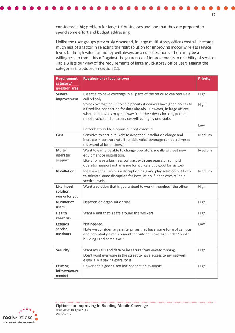
Unlike the user groups previously discussed, in large multi storey offices cost will become much less of a factor in selecting the right solution for improving indoor wireless service levels (although value for money will always be a consideration). There may be a willingness to trade this off against the guarantee of improvements in reliability of service. Table 3 lists our view of the requirements of large multi-storey office users against the categories introduced in section 2.1.
Requirement category/ question area
Requirement / Ideal answer Priority
Service improvement
Essential to have coverage in all parts of the office so can receive a call reliably.
Voice coverage could to be a priority if workers have good access to a fixed line connection for data already. However, in large offices where employees may be away from their desks for long periods mobile voice and data services will be highly desirable.
Better battery life a bonus but not essential
High
High
Low
Cost Sensitive to cost but likely to accept an installation charge and increase in contract rate if reliable voice coverage can be delivered (as essential for business)
Medium
Multi-operator support
Want to easily be able to change operators, ideally without new equipment or installation.
Likely to have a business contract with one operator so multi operator support not an issue for workers but good for visitors.
Medium
Installation Ideally want a minimum disruption plug and play solution but likely to tolerate some disruption for installation if it achieves reliable service levels.
Medium
Likelihood solution works for you
Want a solution that is guaranteed to work throughout the office
High
Number of users
Depends on organisation size
High
Health concerns
Want a unit that is safe around the workers
High
Extends service outdoors
Not needed.
Note we consider large enterprises that have some form of campus and potentially a requirement for outdoor coverage under “public buildings and complexes”.
Low
Security Want my calls and data to be secure from eavesdropping
Don’t want everyone in the street to have access to my network especially if paying extra for it.
High
Existing infrastructure needed
Power and a good fixed line connection available. High

13
Options for Improving In-Building Mobile Coverage Issue date: 18 April 2013 Version: 1.2
Requirement category/ question area
Requirement / Ideal answer Priority
Ability to work in other locations
Would be useful for workers to be able to access a similar service level in other locations under the same contract.
Low
Table 3: Summary of indoor wireless service “wish list” for large multi-storey office users
2.3 Users in public buildings and complexes
Our final category of indoor users is those in public buildings and campuses such as hotels, transport hubs, stadiums, airports, shopping centres and business parks. These differ from the consumer types in the previous sections as they are likely to:
Be on the move and so require both voice and data services
Be sensitive to service price but not to installation costs (as these are borne by the building owners)
Be sensitive to support across multiple operators as users will come from a cross section of service providers
Table 4 lists our view of the requirements of these users against the categories introduced in section 2.1.
Requirement category/ question area
Requirement / Ideal answer Priority
Service improvement
Require both voice and data coverage throughout the building High
Cost Used to free Wi-Fi in public places so would not expect any increase in service charge. Business users may be less sensitive to cost.
High
Multi-operator support
Want service available no matter which operator the user is with. High
Installation Installation borne usually by the operator and in some more limited cases by the building owner so not a concern for the end user.
Low
Likelihood solution works for you
Want a solution that is guaranteed to work throughout the building.
High
Number of users
Depends on building size but potentially very high.
High
Health concerns
Want a unit that is safe around the general public.
High
Extends service outdoors
May be useful in campus environments or business parks.
Low
Security Want my calls and data to be secure from eavesdropping.
High

14
Options for Improving In-Building Mobile Coverage Issue date: 18 April 2013 Version: 1.2
Requirement category/ question area
Requirement / Ideal answer Priority
Existing infrastructure needed
Power and a good fixed line connection likely available in these large public buildings.
High
Ability to work in other locations
Not relevant.
Table 4: Summary of indoor wireless service “wish list” for users in public buildings or areas
2.4 Summary of requirements and priorities across user groups and deployment types
Based on the discussion in the previous sections of this appendix, this section compares the priorities of various in-building service requirements across the user groups and building types examined in this study. Figure 1 compares the priority levels given across the range of in-building service requirements discussed for each of the four categories of user groups and building types.
Figure 1: Summary of priority of requirements across user groups and building types
Table 5 summarises the key differences in priorities and requirements across the four user groups and building types examined in this study. These requirements have then been kept in mind when assessing each in-building solution for suitability against each of these user groups throughout the study.

15
Options for Improving In-Building Mobile Coverage Issue date: 18 April 2013 Version: 1.2
Home users
Small office / SMEs
Large multi storey office
Public buildings and campuses
Better in-home coverage
Improved data rates
Low cost solution that may provide a low cost replacement for my fixed line
Quick and easy to install and ideally just need power
Safe around the family
Ideally support multiple operators but not essential
Largely same drivers as home users
Likely higher capacity requirements than a home user
Less likely to be replacing fixed line connection completely than home user
May be more used to being locked into a single operator through company mobile contract than home user
Highly reliable coverage across all of building essential
Likely to have high capacity requirements
Will be cost sensitive but not as much as home users and SMEs - likely to have a larger budget and willing to trade off higher price for quality of service delivered.
More likely to tolerate a more complex installation
May be used to being locked into a single operator through company mobile contract
Reliable coverage and high data rates as this may differentiate them from other venues
Multi operator support essential
Likely to have very high capacity requirements
Will be cost sensitive but may be willing to make the investment to stimulate business and keep up with competitors
Most likely of the four groups to tolerate large installations
Including some outdoor areas in the solution might be of interest in business parks or campuses
Table 5: Summary of requirements and priorities across user groups and building types
16
Options for Improving In-Building Mobile Coverage Issue date: 18 April 2013 Version: 1.2
3. Appendix B – Detailed description of our quantitative analysis of the size of the in-building problem and factors impacting this in the future
To understand the likely indoor coverage levels delivered by existing macrocellular networks and how these might evolve over time we have carried out a simple quantitative analysis of UK network coverage levels which is described in detail in this appendix.
3.1 Limitations on our analysis
Note that this analysis is intended to indicate the sensitivity of the results to various factors and the scale of the issues. It is not a definitive assessment of absolute numbers, for which more detailed analysis is required. It should be noted that the analysis presented here assumes that consumers are satisfied with coverage in some parts of their building. This gives an optimistic view of the potential size of the in-building service issue compared to the levels reported by consumer surveys which will also reflect consumer dissatisfaction with “patchy” coverage, dropped calls or poor quality voice levels as well as those not able to get coverage in any part of the building.
In this analysis we have also assumed that the spectral efficiency of the network remains constant across time. Our spectrum efficiency to signal quality mapping in taken from the same model as used for Ofcom modelling of spectrum portfolios in the combined award of 2.6GHz and 800MHz spectrum [5]. However, this has been developed with analysing coverage and capacity in 2012 in mind and so may be slightly pessimistic for our 2016 estimates of coverage as enhancements in LTE networks, in the next few years including more use of MIMO and techniques to reduce the signal quality threshold for control and reference signals, may change this mapping.
Furthermore, in 2016 several macrocell sites may have been equipped with four or even eight antennas, and certain mobile devices, e.g. laptops with SIM-integration, could support four antennas. However, the described analysis assumes LTE with 2x2 MIMO.
Finally, the network's spectrum efficiency should improve with time, due to evolution of radio access technologies (LTE-Advanced devices and spectrum are likely to be available in 2015 and usage of COMP MIMO could further increase the spectrum efficiency levels), technology releases within 3G and 4G and better software implementations at both ends of the communication link (i.e. at the mobile device and operator’s network).
3.2 Assumptions, inputs and methodology
Analysis aims, structure and method Within the quantitative analysis carried out in this study we aimed to investigate:
The anticipated change in indoor cellular service over time, for both voice and data (for a 2Mbps cell edge target) services, based on existing and planned network roll out and spectrum acquisitions. For this analysis we have examined potential UK coverage levels at early 2013 and early 2016.
The sensitivity of indoor coverage to additional link budget losses introduced from tighter building regulations regarding the thermal insulation of properties and reductions in mobile device sensitivity due to a trend to include an

17
Options for Improving In-Building Mobile Coverage Issue date: 18 April 2013 Version: 1.2
increasing number of bands. In this analysis we use our estimates of voice and data (for a 2Mbps target service) coverage levels for 2016 as a baseline and then apply additional link budget losses up to 10dB to these.
The sensitivity of indoor coverage to increasing user expectations. In this analysis assume network roll out and availability as expected by 2016 and then report expected coverage levels for a basic voice service and then for data services between 384kbps and 10Mbps.
The potential number of users across the UK requiring an in-building solution as their existing mobile signal levels indoors from the external cellular network will likely not meet expectations. This is examined for user expectations varying from basic voice service to data services between 384kbps and 10Mbps and again assumes network roll out and availability as expected by 2016.
The model used for this analysis is the same as that used to analyse the potential coverage and capacity impact of different spectrum portfolios in Ofcom’s July 2012 statement related to the award of the 800MHz and 2.6GHz spectrum [5]. While this model originally targeted LTE networks, we adjusted this in this study to report coverage for different target maximum allowable path loss values to cover other radio access technologies, target services and frequency bands investigated.
Assumptions regarding network roll out and spectrum availability Within this analysis we have made assumptions on the number of sites, spectrum bands and radio technologies that will be supported for different operator combinations. This assumes that levels of site sharing will increase between operators and as such have modelled one portfolio thought to be representative of the site and spectrum of the two operators with access to sub 1GHz spectrum for GSM and UMTS and another portfolio to be representative of the two operators without sub 1GHz spectrum for GSM and UMTS. Note that we assume a larger increase in sites for the sub 1GHz portfolio by 2016than for the 2nd portfolio modelled without access to sub 1GHz spectrum as this was felt to be representative of the consolidation of networks that has occurred in the UK to date.
In the case of LTE, we have not modelled LTE at 2013 as only EE have a low number of LTE sites currently and so UMTS coverage will still dominate for data services. In the case of LTE at 2016 we assume that all operators have 12k LTE sites and model their spectrum as acquired in the recent auction for the combined award of 800MHz and 2.6GHz as shown in Table 6.
Network Modelled spectrum portfolio for LTE in 2016
Comments
Vodafone 2x10MHz @ 800MHz + 2x20MHz @ 2600MHz
Vodafone has access to 1x25MHz @ 2600MHz. We assume that the coverage from the unpaired spectrum is equal to that of the paired spectrum at the same frequency.
O2 2x10MHz @ 800MHz
EE 2x5MHz @ 800MHz + 2x20MHz @ 2600MHz
We assume that carrier aggregation does not improve coverage and therefore cap the maximum bandwidth to 20MHz. We also assume that the LTE bandwidth at 1800MHz is less than 20MHz, so that high data rate

18
Options for Improving In-Building Mobile Coverage Issue date: 18 April 2013 Version: 1.2
Table 6: LTE spectrum assumptions
Assumptions regarding areas of differing population density In this analysis we look at areas representing different levels of population density in the UK as summarised in Table 7. These areas are defined, in the same way as in Ofcom’s July 2012 statement on the combined award of 800MHz and 2.6GHz spectrum [6], on the basis of local authority district boundaries but they exclude Northern Ireland due to lack of appropriate data. The zero to 50% area is comprised of the most densely populated local authority districts in England, Scotland and Wales where 50% of the population live (from the 2001 census). The 50 to 80% area is comprised of the next most densely populated local authority districts in England, Scotland and Wales where 30% of the population live and so on until the least densely populated 10% of population is reached in the final entry of Table 7.
The study area below … … is referred to in graphs as the following
Example areas of this population density include
0 to 50%, most densely populated
More densely populated areas Greater Manchester
City of Edinburgh
Caerdydd – Cardiff
50 to 80% Cheshire
Fife
Wrecsam – Wrexham
80 to 90% Less densely populated areas Cornwall
South Lanarkshire
90 to 100%, least densely populated
Northumberland
Highland
Powys
Table 7: Summary of population densities examined in our indicative quantitative analysis of indoor coverage
For our analysis of sensitivity of coverage to different changes in cellular networks and factors such as changes in building regulations we have focused on the 0 to 50% case and 80 to 90% cases to represent the majority of users in densely populated areas and users in harder to reach less densely populated areas respectively. However, when assessing the size of the problem across the UK as a whole we consider all four population density categories given on Table 7.
services are routed to the 2600MHz band.
H3G 2x5MHz @ 800MHz + 2x15MHz @ 1800MHz
We assume that H3G acquires EE’s divestment spectrum
Niche Spectrum Ventures
2x15MHz @ 2600MHz We model Niche’s coverage in an example, however the project concentrates on wider area operators

19
Options for Improving In-Building Mobile Coverage Issue date: 18 April 2013 Version: 1.2
3.3 Current and future indoor coverage trends based on network roll out and spectrum availability
Our quantitative analysis shows that based on our understanding of existing networks and spectrum acquisitions and network roll out to 2016, we would expect the existing macrocellular network to provide a good baseline indoor coverage level. In our analysis we have included a site and spectrum portfolio with and without access to sub 1GHz spectrum to show the potential impact of the availability of lower frequency spectrum on indoor coverage levels. The results in Figure 2 show that a voice indoor service should currently be available in at least parts of the building in above 90% of the most densely populated areas of the UK across all site and spectrum portfolios examined. Note that on these graphs the width of each band is due to variability in building loss.
In cases where the consumer is not concerned about having a choice across all operators but is happy to use the operator with the best coverage in their area (the green band on the graphs), and likely the one with access to low frequency spectrum, anticipated coverage in parts of buildings increases to above 98%. Far greater gaps in 2Mbps data services are apparent, although it is anticipated that this will improve greatly in coming years as lower frequencies become more widely deployed for 3G and LTE services.
Figure 2: Indicative indoor coverage levels in 0 to 50% most densely populated areas of the UK for voice (left) and 2Mbps data (right)
Figure 3 shows the situation when examining less densely populated areas where clearly the situation becomes much worse for these harder to reach users representing 10% of the population. It is also worth noting that the gap between the green and red bands is larger in these less densely populated areas than in the most densely populated area results shown earlier indicating that the benefit of having access to low frequency spectrum becomes even greater in these environments.
30%
40%
50%
60%
70%
80%
90%
100%
2013 2016
Service from at least oneoperator
30%
40%
50%
60%
70%
80%
90%
100%
2013 2016
Service from all operators30%
40%
50%
60%
70%
80%
90%
100%
2013 2016
Service from at least oneoperator
30%
40%
50%
60%
70%
80%
90%
100%
2013 2016
Service from all operators
Ind
oo
r p
op
ula
tio
n c
ove
rage
in
mo
re d
ense
ly p
op
ula
ted
are
as
Voice Data
Limited parts of building covered

20
Options for Improving In-Building Mobile Coverage Issue date: 18 April 2013 Version: 1.2
Figure 3: Indicative indoor coverage levels in 80 to 90% less densely populated areas of the UK for voice (left) and 2Mbps data (right)
3.4 Sensitivity of indoor coverage to changes in building regulations and reductions in mobile device sensitivity
Indoor coverage is increasingly challenged due to factors such as changes in building materials, increases in the number of bands included in smart phones and the use of higher frequencies amongst others.
We have investigated the impact of some of these factors in our quantitative analysis. Figure 4 shows the potential impact of additional losses, which may be due to poor device sensitivity through the trend to add more frequency bands to devices and/or changes in building regulations which increase building penetration losses, on coverage levels taking 2016 estimates as a baseline.
Based on the discussion of these factors in the main report in section 3.2.2, the maximum level investigated of 10dB could easily be realised via a combination of:
Premises with windows to meet the new building regulations which could have losses by as much as 9dB more than planned for by operators. While, these will make up a relatively small amount of the domestic population, in commercial buildings it is likely that frequent building revamp programmes would bring building losses to these levels much more rapidly.
The general requirement from operators to support five bands in mobile devices by 2016 leading to losses in the order of 5 to 8dB.
30%
40%
50%
60%
70%
80%
90%
100%
2013 2016
Service from at least oneoperator
30%
40%
50%
60%
70%
80%
90%
100%
2013 2016
Service from all operators30%
40%
50%
60%
70%
80%
90%
100%
2013 2016
Service from at least oneoperator
30%
40%
50%
60%
70%
80%
90%
100%
2013 2016
Service from all operators
Ind
oo
r p
op
ula
tio
n c
ove
rage
in
less
den
sely
po
pu
late
d a
reas
Voice Data
Limited parts of building covered

21
Options for Improving In-Building Mobile Coverage Issue date: 18 April 2013 Version: 1.2
Figure 4: The impact of additional losses due to increased frequency bands in devices and/or changes to building regulations on GSM voice coverage as anticipated for 2016 for most densely populated areas
Figure 4 shows that while coverage is negatively impacted this is not by a vast amount if consumers are willing to be limited in choice to the operators who serves them best. However, Figure 5 shows the situation in less densely populated areas which, as expected due to lower starting coverage levels, see much more of an impact.
Figure 5: The impact of additional losses due to increased frequency bands in devices and/or changes to building regulations on GSM voice coverage as anticipated for 2016 for less densely populated areas
Figure 6 and Figure 7 show the impact on data services of additional losses in the link budget for LTE data services targeting a 2Mbps service. These show a more dramatic impact on data coverage, even in more densely populated areas, due to the starting coverage levels of being lower than in the case of GSM voice services.
30%
40%
50%
60%
70%
80%
90%
100%
0dB 5dB 10dB
Service from at least oneoperator
30%
40%
50%
60%
70%
80%
90%
100%
0dB 5dB 10dB
Service from all operators
Ind
oo
r p
op
ula
tio
n c
ove
rage
in
mo
re d
ense
ly p
op
ula
ted
are
as
Additional loss in the link budget
Limited parts of building covered
30%
40%
50%
60%
70%
80%
90%
100%
0dB 5dB 10dB
Service from at least oneoperator
30%
40%
50%
60%
70%
80%
90%
100%
0dB 5dB 10dB
Service from all operators
Ind
oo
r p
op
ula
tio
n c
ove
rage
in
less
den
sely
po
pu
late
d a
reas
Additional loss in the link budget
Limited parts of building covered

22
Options for Improving In-Building Mobile Coverage Issue date: 18 April 2013 Version: 1.2
Figure 6: The impact of additional losses due to increased frequency bands in devices and/or changes to building regulations on LTE 2Mbps coverage as anticipated for 2016 for most densely populated areas
Figure 7: The impact of additional losses due to increased frequency bands in devices and/or changes to building regulations on LTE 2Mbps coverage as anticipated for 2016 for less densely populated areas
The impact is even worse if support for legacy data devices with 3G support only as shown in Figure 8 and Figure 9.
30%
40%
50%
60%
70%
80%
90%
100%
0dB 5dB 10dB
Service from at least oneoperator
30%
40%
50%
60%
70%
80%
90%
100%
0dB 5dB 10dB
Service from all operators
Additional loss in the link budget
Limited parts of building covered
Ind
oo
r p
op
ula
tio
n c
ove
rage
in
mo
re d
ense
ly p
op
ula
ted
are
as
30%
40%
50%
60%
70%
80%
90%
100%
0dB 5dB 10dB
Service from at least oneoperator
30%
40%
50%
60%
70%
80%
90%
100%
0dB 5dB 10dB
Service from all operators
Additional loss in the link budget
Limited parts of building covered
Ind
oo
r p
op
ula
tio
n c
ove
rage
in
less
den
sely
po
pu
late
d a
reas

23
Options for Improving In-Building Mobile Coverage Issue date: 18 April 2013 Version: 1.2
Figure 8: The impact of additional losses due to increased frequency bands in devices and/or changes to building regulations on 3G 2Mbps coverage as anticipated for 2016 for most densely populated areas
Figure 9: The impact of additional losses due to increased frequency bands in devices and/or changes to building regulations on 3G 2Mbps coverage as anticipated for 2016 for less densely populated areas
3.5 Sensitivity of indoor coverage to changes in user expectations of mobile services
We also examined the sensitivity of indoor coverage levels in the UK to changes in user expectations. We have done this by estimating coverage levels, assuming network roll out and spectrum availability as per 2016, for a range of target service levels from basic voice to a 10Mbps data service. Figure 10 and Figure 11 show the results of this analysis of the impact of changing user expectations. Of all the factors investigated these illustrate that the impact of user expectations on indoor service levels will likely be the most significant negative factor.
30%
40%
50%
60%
70%
80%
90%
100%
0dB 5dB 10dB
Service from at least oneoperator
30%
40%
50%
60%
70%
80%
90%
100%
0dB 5dB 10dB
Service from all operators
Additional loss in the link budget
Limited parts of building covered
Ind
oo
r p
op
ula
tio
n c
ove
rage
in
mo
re d
ense
ly p
op
ula
ted
are
as
30%
40%
50%
60%
70%
80%
90%
100%
0dB 5dB 10dB
Service from at least oneoperator
30%
40%
50%
60%
70%
80%
90%
100%
0dB 5dB 10dB
Service from all operators
Additional loss in the link budget
Limited parts of building covered
Ind
oo
r p
op
ula
tio
n c
ove
rage
in
less
den
sely
po
pu
late
d a
reas

24
Options for Improving In-Building Mobile Coverage Issue date: 18 April 2013 Version: 1.2
Figure 10: The impact of user data rate expectations on coverage as anticipated for 2016 for most densely populated areas
Figure 11: The impact of user data rate expectations on coverage as anticipated for 2016 for less densely populated areas
The upper bound of this graph of 10Mbps may appear to be an ambitious target but is slightly below the average fixed broadband speed reported by Ofcom for the UK in 2012 [7][8] so is reasonable if consumers are looking to mobile indoor services to completely replace or as a competitive complement or fall-back option for their existing fixed line connection.
For completeness we have also modelled the indoor coverage levels that could be expected when new entrant service providers, such as Niche Spectrum Ventures, with access only to spectrum at 2.6GHz are considered. In this case LTE coverage levels would reach low levels even in the most densely populated areas if consumers required the option of service across all operators, as shown by the red band in Figure 12. However,
30%
40%
50%
60%
70%
80%
90%
100%
2G/3Gvoice
3G/LTE384kbps
3G/LTE2Mbps
3G/LTE5Mbps
3G/LTE10Mbps
Service from at least one operator
30%
40%
50%
60%
70%
80%
90%
100%
2G/3Gvoice
3G/LTE384kbps
3G/LTE2Mbps
3G/LTE5Mbps
3G/LTE10Mbps
Service from all operators
Ind
oo
r p
op
ula
tio
n c
ove
rage
in
mo
re d
ense
ly p
op
ula
ted
are
as
Limited parts of building covered
2G voice
Leading operator with low frequency spectrum provides HSPA or LTE depending on the construction materials. Others rely on HSPA coverage at this point.
Leading operator provides LTE service with better coverage than HSPA
x-axis not to scale
HSPA coverage better than LTE for operator without low frequency spectrum for HSPA as 3G network more dense and LTE bandwidth limited
HSPA and LTE services from other operators competing for better service
30%
40%
50%
60%
70%
80%
90%
100%
2G/3Gvoice
3G/LTE384kbps
3G/LTE2Mbps
3G/LTE5Mbps
3G/LTE10Mbps
Service from at least one operator
30%
40%
50%
60%
70%
80%
90%
100%
2G/3Gvoice
3G/LTE384kbps
3G/LTE2Mbps
3G/LTE5Mbps
3G/LTE10Mbps
Service from all operators
Ind
oo
r p
op
ula
tio
n c
ove
rage
in
less
den
sely
po
pu
late
d a
reas
Limited parts of building covered
GSM 1800Operator with LTE at 800
Leading operator with LTE at 800 and 2600
GSM 900
HSPA 900
Other operators with LTE at 800, 2600 or HSPA
x-axis not to scale

25
Options for Improving In-Building Mobile Coverage Issue date: 18 April 2013 Version: 1.2
this is not thought to be a representative result as it is unlikely that operators with access to 2.6GHz alone would be aiming to provide mobile services on a nationwide basis and instead would be targeting particular towns and local areas. Therefore in the remainder of our analysis we only consider coverage levels estimated based on the likely capabilities of wide area network operators as reported already in Figure 10 and Figure 11.
Figure 12: The impact of user data rate expectations on coverage as anticipated for 2016 for most densely populated areas when an LTE operator with 2.6GHz spectrum alone is also considered (red band)
3.6 Our quantitative analysis of the potential size of the in-building problem
Having shown in the previous section that the growth in user expectations of mobile service levels is likely to have the biggest future impact on indoor mobile service levels, this section looks at the number of in-building solutions that potentially might be needed across the UK for different scenarios of varying user expectation levels.
Figure 13 shows the overall percentage of the population in the UK by 2016 likely to have coverage from at least one operator in parts of their building for voice and mobile data services of varying rates. Here we see that if users are satisfied with voice as a minimum service level that coverage levels are very high, in the order of 97%, but applying a requirement for data services of 2Mbps in line with the government’s Digital Britain targets takes this dramatically down to around 85%. In the extreme case that users look to substitute their fixed line connections with mobile services and require data rates of 10Mbps then less than half of the population would be able to receive this service level from any operator.
30%
40%
50%
60%
70%
80%
90%
100%
2G/3Gvoice
3G/LTE384kbps
3G/LTE2Mbps
3G/LTE5Mbps
3G/LTE10Mbps
Service from at least one operator
30%
40%
50%
60%
70%
80%
90%
100%
2G/3Gvoice
3G/LTE384kbps
3G/LTE2Mbps
3G/LTE5Mbps
3G/LTE10Mbps
Service from all operators (LTE)
30%
40%
50%
60%
70%
80%
90%
100%
2G/3Gvoice
3G/LTE384kbps
3G/LTE2Mbps
3G/LTE5Mbps
3G/LTE10Mbps
Service from all operators (3G)Ind
oo
r p
op
ula
tio
n c
ove
rage
in
mo
re d
ense
ly p
op
ula
ted
are
asLimited parts of building covered
x-axis not to scale

26
Options for Improving In-Building Mobile Coverage Issue date: 18 April 2013 Version: 1.2
Figure 13: Percentage of UK population by 2016 with service in parts of their building from at least one operator for varying indoor service expectations
Figure 14 then translates the coverage percentage from Figure 13 into the number of users potentially requiring an in-building solution of some kind because they are unable to get coverage in any part of their building from any operator for the target service level shown on the x axis. The number of users impacted in the different areas of population density is shown by the different colours on the graph on a cumulative basis. For example the purple area represents the number of users impacted in the most densely populated areas i.e. the first 50% of the population in order of the most densely populated first. The yellow area then represents the number of users impacted in the next most densely populated areas containing a further 30% of the population i.e. from 50% to 80%. This yellow area is stacked on top of the purple area to show the cumulative number of users if the number of users impacted in the 80% most densely populated areas of the UK was of interest. This stacking continues for next 10% of the population from 80 to 90% and then on to the final 10% from 90 to 100% represented by the grey area.
Given variations in building construction when modelling coverage, a range is shown for each population density area using a stacked area plot to show the lower limits and stacked line plot to show the upper limits on this so that:
The stacked area plot shows the cumulative number of indoor solutions assuming a low penetration loss leading to a low estimate of users impacted
The stacked lines indicate how the number of solutions is affected by the construction materials and assumes a high penetration loss leading to a high estimate of users impacted
96.04%
87.03%84.14%
69.35%
44.16%
97.25%
90.24%86.92%
73.30%
46.16%
30%
40%
50%
60%
70%
80%
90%
100%
2G/3Gvoice
3G/LTE384kbps
3G/LTE2Mbps
3G/LTE5Mbps
3G/LTE10MbpsIn
do
or
po
pu
lati
on
co
vera
ge in
th
e U
KLikely range of variation due to building construction
Limited parts of building covered
x-axis not to scale

27
Options for Improving In-Building Mobile Coverage Issue date: 18 April 2013 Version: 1.2
Figure 14: Number of users requiring indoor solutions as unable to get indoor service from at least one operator in parts of their building for varying service expectations
From this we see that if users are satisfied with just receiving voice services in 2016 then it is likely that approximately 2m users across the UK would require an in-building solution due to lack of service from any operator. If a 2Mbps service in line with Digital Britain is required then approximately 2m users would require solutions if targeting the most densely populated areas where half the UK population lives, but this grows rapidly to around 7.5m users if all UK population is considered. In the most extreme case, 15m indoor users require in-building solutions to bring 10Mbps broadband to half of the population, i.e. 0 to 50% and in order to cover the 50% to 90% of the population, another 15m users require solutions giving 30m indoor solutions in total which corresponds to 1 in every 2 households. In order to cover the last 10% of the population in this case, another 5m users require solutions giving 35m in total and meaning that almost every household in the last 10% requires an indoor solution.
If we allow for users wanting choice across operators, Figure 15 and Figure 16 show the number of users requiring an in-building solution as they do not already have service from all operators’ macrocellular networks indoors. In this case if the user is satisfied with voice services alone then 5.5m users will still need in-building solutions to achieve this from a choice of all operators i.e. 2.5 times that if operator choice is not crucial then 5m users require an in-building solution in the most densely populated areas alone, zero to 50%, and 14m users if all areas of the UK are to be covered i.e. double that if operator choice is not an issue. In the extreme case of a 10Mbps service 20, 35 and 40m users require in-building solutions to cover 50, 90 and 100% of the population respectively. This final result is not such a dramatic increase on the case where operator choice is not an issue as for this high data rate case most buildings require an in-building solution in either case.
0
5,000,000
10,000,000
15,000,000
20,000,000
25,000,000
2G/3Gvoice
3G/LTE384kbps
3G/LTE2Mbps
3G/LTE5Mbps
3G/LTE10Mbps
0 to 50%, more densely populated50 to 80%
80 to 90%90 to 100%, less densely populated
Nu
mb
er o
f u
sers
req
uir
ing
an in
do
or
solu
tio
n b
ecau
se t
hei
r se
rvic
e is
lim
ited
to
par
ts o
f th
e b
uild
ing,
cu
mu
lati
ve in
ar
eas
of
dif
fere
nt
po
pu
lati
on
den
sity
Number of indoor required solutions for urban users (high estimate)
Number of indoor required solutions for urban users (low estimate)

28
Options for Improving In-Building Mobile Coverage Issue date: 18 April 2013 Version: 1.2
Figure 15: Percentage of UK population with service in parts of their building from all operators for varying indoor service expectations
Figure 16: Number of users requiring indoor solutions as unable to get indoor service from all operators in parts of their building for varying service expectations
3.7 Summary of key findings
This section reviews and summarises findings from our quantitative analysis during this study.
83.06%
73.08%
66.37%
45.84%
89.68%
82.56%
75.90%
59.75%
31.88%30%
40%
50%
60%
70%
80%
90%
100%
2G/3Gvoice
3G/LTE384kbps
3G/LTE2Mbps
3G/LTE5Mbps
3G/LTE10MbpsIn
do
or
po
pu
lati
on
co
vera
ge in
th
e U
K
Likely range of variation due to building construction
Limited parts of building covered
x-axis not to scale
0
5,000,000
10,000,000
15,000,000
20,000,000
25,000,000
2G/3Gvoice
3G/LTE384kbps
3G/LTE2Mbps
3G/LTE5Mbps
3G/LTE10Mbps
0 to 50%, more densely populated50 to 80%
80 to 90%90 to 100%, less densely populated
Nu
mb
er o
f u
sers
req
uir
ing
an in
do
or
solu
tio
n b
ecau
se t
hei
r se
rvic
e is
lim
ited
to
par
ts o
f th
e b
uild
ing,
cu
mu
lati
ve in
ar
eas
of
dif
fere
nt
po
pu
lati
on
den
sity
Number of indoor required solutions for urban users (high estimate)
Number of indoor required solutions for urban users (low estimate)

29
Options for Improving In-Building Mobile Coverage Issue date: 18 April 2013 Version: 1.2
3.7.1 Estimates of current and future indoor coverage based on network roll out and spectrum availability
Our estimates of indoor coverage between today and 2016 show that:
A voice indoor service should currently be available in at least parts of the building from all operators in above 90% of premises in the most densely populated areas of the UK. This rise to 98% if consumers are willing to use the operator with the best coverage in their area and be restricted in choice.
The level of voice coverage between now and 2016 does not rise much as it is already at a very high level.
In the case of 2Mbps data services, this should be available from at least one operator in approximately 80% of premises in the most densely populated areas today and should improve to beyond 90% by 2016.
In less densely populated areas with harder to reach users voice coverage from at least one operator should be around 90% of premises and rising to 93% by 2016. In the case of a 2Mbps data service coverage is only currently estimated at 55% for service from at least one operator and rising to 75% by 2016.
Across the UK as a whole by 2016 indoor voice coverage should be at around 98% for service from at least one operator with coverage for a modest data service of 2Mbps at around 87%.
3.7.2 Factors impacting indoor coverage levels
Key findings from our sensitivity analysis of in-building coverage levels due to different factors include:
The impact of changes in building regulations and reduced receiver sensitivity in the most densely populated areas is likely to be marginal (in the order of 2%), in terms of coverage percentage, particularly if consumers are willing to use the operator with the best signal in their area rather than insisting on a choice across all operators. However, as 50% of premises fall into this category this could potentially still impact in the order of 600,000 people in these most densely populated areas of the UK. In the case of data the situation is worse with a potential drop in coverage of over 10% in these densely populated areas potentially impacting in the order of 3m people in these areas.
In the case of less densely populated areas representing 10% of the population while the impact of changes in building regulations and reduced receiver sensitivity is worse in percentage terms at approximately 10% and 25% for voice and data services respectively this translates to the same or even a lower volume of people impacted than in the more densely populated areas with 600,000 people affected for voice services and 1.5m people affected for data services (if choice across all operators is not needed).
Of the factors investigated the increase in user expectations of increased data rates is likely to have the most significant impact and this is quantified in terms of the number of in-building solutions potentially required across the UK in the final part of our analysis.

30
Options for Improving In-Building Mobile Coverage Issue date: 18 April 2013 Version: 1.2
3.7.3 The potential size of the in-building problem
Findings with respect to the potential volume of users requiring an in-building solution for varying levels of user expectation are summarised and compared in Table 8. This highlights that even at the lowest levels of service expectations, a significant volume – if not percentage – of users will require in-building solutions, even if prepared to be limited in their choice of mobile operator. Note that as highlighted in earlier sections, this indicative analysis assumes that consumers are happy with receiving service in parts of their building and does not incorporate the users who feel they need an in-building solution because they have patchy coverage, suffer from dropped calls or generally just want to boost their indoor data rates. Therefore the figures here are likely to give a low estimate of the size of the indoor service problem which is reflected when compared to industry sources on the size of the problem.
Service being targeted
Number of users requiring solutions if operator choice not an issue
Number of users requiring solutions if choice across all operators needed
Comments
Voice 2m for all of UK 5.5m for all of UK Even for the most basic service a significant volume of users are impacted.
2.5 times as many in-building solutions needed if operator choice essential.
2Mbps 2m for 50% most densely populated
7.5m for all parts of the UK
5m for 50% most densely populated
14m for all parts of the UK
2 times as many in-building solutions needed if operator choice essential.
Reaching the first half of the population accounts for a third or less of the solutions needed in both cases.
10Mbps 15m for 50% most densely populated
30m for 90% most densely populated
35m for all parts of the UK
20m for 50% most densely populated
35m for 90% most densely populated
40m for all parts of the UK
No change in the number of solutions needed between the two scenarios for the more difficult to reach percentages of population as even in the limited choice of operator case close to a solution per household is needed for these difficult to reach users.
Table 8: Summary of the potential volume of users requiring in-building solutions assuming networks at 2016 deployment levels for different service expectations and requirements on choice across operators
Also note that in our analysis we modelled spectrum portfolios with and without access to lower frequency spectrum and that the coverage results when consumers are satisfied with a limited choice of operators in their area, i.e. accepting being limited to the operator with the best coverage level in their area, that this tends to represent a site and spectrum portfolio with access to lower frequency bands. However, for the case when a choice across all operators is required by consumers the coverage results tend to be limited by the site and spectrum portfolio modelled without access to lower frequency

31
Options for Improving In-Building Mobile Coverage Issue date: 18 April 2013 Version: 1.2
bands. Therefore from Table 8 it can be seen that in the case of voice and a 2Mbps target data service that availability of low frequency spectrum to all operators could roughly halve the number of dedicated in-building solutions needed in the UK by 2016.

32
Options for Improving In-Building Mobile Coverage Issue date: 18 April 2013 Version: 1.2
4. Appendix C – Detailed discussion of outside-in solutions for in-building service issues
This appendix describes and assesses so called “outside-in” solutions for improving in-building coverage levels. These include direct improvements to the existing outdoor macrocellular network, including either site upgrades or new site builds, and the deployment of outdoor small cells to enhance the existing outdoor macrocellular network. For each of these we provide:
An assessment against the requirements of the indoor user groups presented in appendix A
An assessment against the study requirements originally set by Ofcom to highlight any areas of concern.
4.1 Macrocell enhancements
In the same way that outdoor cellular service levels have benefited from advancements in macrocellular networks over time so too will indoor service levels. Despite fierce competition in the mobile terminals sphere, there is still a large variation in the RF performance of handsets which must meet the basic performance characteristics as specified by 3GPP. Apart from type approval before a handset is included in a network operator’s product range, there is not much improvement a network operator can perform on the handsets as they have to serve a large spectrum of customers who may use a wide range of handsets ranging from the basic to high end. Therefore network enhancements are discussed in this section from the perspective of improvements by the operator to their sites and basestation equipment.
Figure 17: Some example macrocell sites
Cellular network improvements are likely to continue for the foreseeable future due to:
Upgrades to existing macrocell sites including: o Network modernisation o Higher effective transmit power levels o Backhaul improvements. o Carrier aggregation o Sector addition o Sector relocation or re-orientation o The introduction of advanced technologies like MIMO and CoMP

33
Options for Improving In-Building Mobile Coverage Issue date: 18 April 2013 Version: 1.2
o General radio access technology evolution from GSM to 3G to LTE and LTE-A
o Use of low frequency spectrum or more spectrum
Building new macrocells
Macrocell site sharing
4.1.1 Consumer proposition
Most macrocell upgrades or new site builds will appear to the user as a transparent improvement in their existing service level. In terms of the service level that the user sees this may mean having coverage where little or no service previously existed. It may also mean an increase in data rates achieved from previously or a combination of both of these.
Other improvements that consumers may see will include lower latency or delays due to network enhancements that improve capacity and hence reduce contention for resources. Handset battery life will also likely improve with the majority of network enhancements mentioned due to improved levels of spectrum efficiency in these techniques requiring a lower transmit power level from handsets generally.
In the case of some macrocell upgrades, such as the inclusion of LTE-A features, the consumer will need to have the latest LTE-A handset to make the most of the service improvements. However, even those with legacy handsets will see some improvement due to the effective “offloading” of some users to more efficient technologies.
Table 9 indicates the level of service improvement that macrocell enhancements are likely to bring to the user groups and building types discussed in appendix A with red indicating the solution is not suited to this building type, amber indicating that some but not all buildings in this category will see a service improvement and green indicating that the majority of buildings in this category will see a service improvement.
Home user Small office / SME Large multi storey office
Public buildings / areas
Likely to improve service levels in the vast majority of small premises in terms of:
- coverage where poor or some previously existed
- improved download speeds
- lower latency or delay on services i.e. video streaming less jittery
Handset battery life will also likely improve
As for home users Will deliver some service improvement in parts of the building but in majority of large, multi-storey buildings will not provide reliable service to all parts of the building.
As for large multi storey offices.
Table 9: Impact of macrocell enhancements across building types

34
Options for Improving In-Building Mobile Coverage Issue date: 18 April 2013 Version: 1.2
Macrocell enhancements are likely to have the biggest impact on smaller buildings where the outdoor signal is likely to penetrate into most areas. However, for larger multi storey buildings it is likely that, although service levels will be improved in some parts, outdoor signals will fail to penetrate into all areas where service is needed and so will not provide a complete solution to user requirements in these buildings.
4.1.2 Concept in more detail
As already highlighted, the outdoor and indoor performance of macrocellular networks is likely to continue to improve for the foreseeable future due to:
Upgrades to existing macrocell sites including: o Network modernisation o Higher effective transmit power levels o Backhaul improvements. o Carrier aggregation o Sector addition o Sector relocation or re-orientation o The introduction of advanced technologies like MIMO and CoMP o General radio access technology evolution from GSM to 3G to LTE and
LTE-A o Use of low frequency spectrum or more spectrum
Building new macrocells
Macrocell site sharing
Each of these are described in more detail in this section.
Network upgrades - Network modernisation This includes replacing older base stations and equipment on macrocell sites with the latest state of the art ones which may improve coverage and user experience levels. Most UK operators have gone through their GSM refresh programme which will have enhanced GSM service levels. These improvements in equipment tend to more accurately define a cell’s coverage area and so can improve coverage in some cases.
Network upgrades - Higher effective transmit power levels In some cellular bands operators have made requests for increases in the maximum allowable EIRP level and have had these approved within their existing licences. For example, at 2100MHz the EIRP increase from 56dBm to 62dBm has been approved. This increase in EIRP will directly increase downlink coverage levels in areas where it was previously limited.
This increase in EIRP could be achieved by operators during their network refresh programme. Within the confines of radiation safety limits, there are several ways to increase the EIRP of a base station including:
Using a higher output power amplifier
Using remote radio head which overcomes the feeder loss between the base station equipment and the antenna. A remote radio head is basically separating the RF unit from the base band equipment which contains all the intelligence of processing the traffic. The connection can be in the form of coaxial cable or, more likely, an optical fibre which reduces the feeder losses significantly on

35
Options for Improving In-Building Mobile Coverage Issue date: 18 April 2013 Version: 1.2
existing sites where the base station is some distance from the antenna. The remote radio head can either be mounted at the base of the antenna mounting structure, or mounted near the antenna up on the tower or pole mount on a rooftop site. A low noise amplifier is normally incorporated in the remote radio head unit to improve the uplink noise performance.
Using a higher gain antenna. Apart from replacing an omni antenna by a sectorised antenna, the upgrade of antennas is rarely undertaken by network operators because it has a potential impact on network planning as well as the appearance of the site. A higher gain antenna generally means a longer or broader antenna structure is needed. This will affect the wind loading of the support structure which may require upgrade, and it also changes the appearance of the radiating structure which may, in certain circumstances, require planning approval. These are costly and time consuming processes. It also changes the coverage footprint which is carefully planned to fit in with the surrounding macrocells.
Network upgrades - Backhaul improvements Often in suburban areas a site’s backhaul capacity may be limited initially because of the expense of or availability of high bandwidth leased line options. All UK operators are in the process of changing over from leased line to IP based backhaul technologies. This usually offers a much bigger bandwidth and better re-configuration flexibility at a lower cost. This should improve the backhaul capacity of sites resulting in an improved user experience across a cell. However, this will not improve the coverage area of the site directly.
Network upgrades - Carrier aggregation, more spectrum This is a technique proposed in both HSPA+ and LTE-Advanced where an end user device is not limited to the capacity of a given bandwidth on a single carrier but can also make use of or “aggregate” service across multiple carriers. If multiple bands are supported at the basestation this technique will improve the quality of experience levels across the cell for both multi-band handsets and legacy handsets (due to the latest handsets being “offloaded” to the extra bands). However, coverage at low cell edge rates is unlikely to be extended as these will still be limited by the quality of control and reference signals.
Figure 18: Scalable bandwidths and carrier aggregation in LTE and LTE-A. Source: Real Wireless [9]
LTE Rel-8Single Scalable Bandwidth Carrier
LTE-AdvancedAggregation of Multiple ‘Component Carriers’
Intra-bandAdjacent
Intra-bandNon-adjacent
Inter-band
1.4 MHz
5 MHz
20 MHz
3, 10, 15MHz bandwidths Also supported
Up to 5 CCs or 100MHz

36
Options for Improving In-Building Mobile Coverage Issue date: 18 April 2013 Version: 1.2
Network upgrades - Sector addition Operators sometimes upgrade sites from 3 to 6 sectors to increase the capacity of a site. However, this is generally costly to do and therefore only done in cases where all other options for adding capacity have been exhausted. Additional sectors will improve quality of experience across the cell but, due to the same EIRP limit applying in the new sectors, will not directly improve the coverage area of the site. The addition of sectors that have not had prior planning or landlord approval as part of the original agreement between the operator and site owner will be time consuming and expensive to obtain the necessary approvals – in some cases approval may not be granted at all.
Network upgrades - Sector relocation or re-orientation The introduction of remote radio heads (RRH) means that sectors can now be relocated or re-orientated more easily than in the past and hence the coverage footprint of a cell altered. At the same time, the effective power from the antenna may be increased because of the removal of the losses in the coaxial feeder cable which is replaced by the RRH. This will not be the case if the operator was already transmitting at the maximum licenced EIRP. Also it should be noted that the practice of sector relocation or re-orientation does not happen very often in UK networks currently. This is in part due to the fact that a new planning application and landlord agreement may be required, both of which are time consuming to prepare/negotiate and with no guarantee of success at the end.
Network upgrades - MIMO Multiple input, multiple output technology makes use of the spatial diversity of paths between multiple antennas to make improvements to the received signal quality or to multiplex additional data streams across sufficiently de-correlated spatial paths. This is included in HPSA+, LTE and LTE-advanced with 2x2 MIMO likely to form the baseline deployment level for LTE. The result will be an improvement in both coverage and quality of experience across the cell although users may have to upgrade their handset to be able to enjoy these benefits.
Network upgrades - CoMP Coordinated multipoint transmissions makes use of a low latency dedicated connection between basestations (the X2 link in LTE) to coordinate and schedule transmissions to mobile devices and can give processing gains in the same way as MIMO or reduce interference between cells. If this is deployed it will improve both the coverage and quality of experience across a cell. However, indications from industry are that CoMP is some way from being realised in commercial networks and may never be a realistically cost effective solution [9]. Coordinated multipoint transmissions largely falls into two groups as follows:
Joint Processing (JP): A mobile device can have multiple serving cells, requiring user data to be transmitted (or received) in multiple locations. This requires sharing of both scheduling information and the users’ data between neighbour cells.
Co-ordinated Scheduling (CS): A mobile device only has one serving cell so no sharing of user data is required. Scheduling information is shared between neighbour cells in order to avoid or reduce interference. Scheduling information could be power levels per resource block, load levels, beamforming weights, etc. CS schemes require less information sharing and processing than JP, but do not in general achieve such high potential capacity gains.

37
Options for Improving In-Building Mobile Coverage Issue date: 18 April 2013 Version: 1.2
Figure 19: Example CoMP scenario. Source: Real Wireless [9]
Network upgrades - GSM, 3G to LTE evolution The evolution of cellular air interfaces brings with it improvements in spectrum efficiency which the user will experience in terms of improved data rates for the same signal quality levels. Coverage improvements may also be apparent depending on the cell edge service being targeted and whether the coverage area of the cell is determined by the reception of control and reference signals (although there will likely be improvements even in the reception of these as radio technologies evolve) or the signal quality required to achieve the target cell edge service level.
Figure 20: Expected evolution of spectrum efficiency in UK cellular networks over time. Source: Real Wireless [9]
Network upgrades - Use low frequency spectrum or more spectrum The availability of low frequency spectrum should bring coverage improvements to consumers due to the enhanced propagation characteristics at lower frequencies (provided the consumer has a handset to support these new frequency bands). More spectrum becoming available at higher frequencies will improve capacity and the quality of experience across a cell but may not directly improve coverage depending on the cell edge service level being targeted. This is again because the coverage area of a cell tends to be limited by the reception of reference and control signals which will not benefit from wider bandwidths and indeed tend to be focused in the smallest bandwidth supported by a network to support backwards compatibility with legacy mobile devices.
38
Options for Improving In-Building Mobile Coverage Issue date: 18 April 2013 Version: 1.2
Building new macrocells In areas where cellular service levels are particularly challenged operators may opt to build new macrocells or site share with another operator. This will improve coverage for users potentially in areas where a poor service level or no service existed before. Initiatives such as the Coverage Obligation included at 800MHz and the Mobile Infrastructure Project will mean that operators are likely to continue to build new sites in the near future to address areas with poor existing service levels. However, it in practice it will not be economically viable to provide indoor coverage with 100% reliability to 100% of premises using costly macrocells alone whose signals will always struggle to penetrate the walls of some buildings with exceptionally challenging construction materials and geometries.
Mobile networks are also dependant on their rooftop sites remaining in fixed locations and in urban areas but where building owners may wish to redevelop their buildings the cellsites may need to be relocated or replaced completely. This may result in changes in the service consumers will experience in the surrounding area depending on the type of replacement sites that can be acquired and installed by the operator.
Macrocell site sharing The sharing of macrocell sites is widely supported across UK operators. In the UK there are two main sharing arrangements in place between the four MNOs: Mobile Broadband Networks Ltd (MBNL) and Cornerstone Telecommunications Infrastructure Ltd (CTIL) [10].
MBNL is jointly owned by Three and Everything Everywhere and is an example of sharing of active equipment between operators with the transmitter sites, base station equipment and backhaul for the 3G network shared but each operator still running a separate logical network and using their own spectrum except where roaming arrangements are in place. This is an example of a Multi-Operator Radio Access Network (MORAN) system. CTIL is essentially a site sharing arrangement between O2 and Vodafone where sharing is limited to the shared use of physical assets at the basestation with active equipment for each network being maintained separately. This is an example of passive sharing. A third sharing arrangement similar to MORAN but where a single or series of shared carriers are used to feed a shared Radio Access Network (RAN) and multiple core networks is known as MOCN. However, this has the disadvantage that spectrum sharing between operators must be allowed [11]. While MORAN is a commonly applied industry practice for site sharing no standards exist for it directly. However, in the case of MOCN 3GPP standards do exist for both UMTS and LTE networks in, for example, TS 23.251 [12]
In the case of our indicative quantitative analysis of voice coverage levels between today and 2016, described in appendix B, the “Service from at least one operator” case shown in Figure 21 assumes a large increase in sites (50%) becoming available through a site sharing arrangement (and no change in frequency band between the two time points). This highlights that in areas where coverage is already very high, site sharing even on a large scale is unlikely to improve coverage levels further. However, in harder to reach areas starting from a lower coverage level the improvement seen will be more significant.
In the “Service from all operators” case we assume that most gains from site sharing have already been realised by these operators by 2013 and so a much more modest site increase of 20% is assumed. As can be seen by the red band in both cases this has largely no impact on the coverage situation primarily because operators tend to cover similar

39
Options for Improving In-Building Mobile Coverage Issue date: 18 April 2013 Version: 1.2
areas and so shared sites, after an initial big increase in site numbers due to site sharing, are unlikely to target not-spot areas.
Figure 21: Improvement in voice coverage over time in densely and less densely populated areas (where for the green band “service from at least one operator” a 50% increase in sites is assumed between 2013 and 2016)
4.1.3 Standards
Generally, the architecture and interfaces for macrocells and the technology enhancements referred to here have been well defined and standardised in 3GPP. However, it should be noted that the existence of standards does not guarantee interoperability and that interoperability testing is required as an additional step to standardisation. This means that for some newer features in the standards such as self-organising networks (SON) and CoMP which are at the early stage of development by vendors and still require interoperability testing to prove interfaces and overcome latency issues. Also the standards only define basic functionality of these newer features and do not specifiy their full implementation meaning that the performance enhancements seen will depend on the proprietary implementation the vendor of the basestation equipment and will differ between vendors.
Security No major security concerns were identified for the macrocell enhancements referred to here as the security requirements for many of these features remain the same as for existing macrocell networks as standardised in 3GPP. An emerging area to monitor is the movement of more network intelligence from the core network into basestations and the use of IP based and potentially shared backhaul connections in LTE. These raise some concerns about the security of eNode Bs, their authentication with the network, securing their backhaul connections and the physical form of X2 connections between eNBs (which is not yet clear). However, many of the security features already specified for small cells in 3GPP (see appendix E re cellular small cells) which will be much more vulnerable than operator deployed eNBs can be applied to address these concerns.
One issue to keep in mind when site sharing is applied is the boundaries of responsibility for Lawful Intercept and ensuring that only the home operator has knowledge of any Lawful Intercept orders served. These issues are currently being considered by both GSMA and 3GPP but should be monitored by Ofcom.
40
Options for Improving In-Building Mobile Coverage Issue date: 18 April 2013 Version: 1.2
Authentication and handover Again no concerns were identified in these areas as authentication and handover are this is already well standardised for macrocells within 3GPP. Macrocells have been designed with mobility in mind and so generally do not suffer from the handover issues of many other in-building solutions.
4.1.4 Industry ecosystem
Interoperability and openness: There are a number of existing cellular basestation and antenna manufacturers to provide the equipment to operators to support the macrocell enhancements that have been suggested. The barrier to new entrant manufacturers is high but not prohibitive. This has been demonstrated by the recent non-European growth of vendors such as Huawei and Samsung.
Generally the 3GPP standards provide clear specifications for the architecture and interfaces for macrocellular basestations and supporting RAN equipment. Therefore there are, technically, no barriers to new entrant vendors. However, the high investment levels needed to get a new entrant vendor in this area is for many prohibitively high.
Multi operator support: Generally there is nothing to prohibit operators from following similar macrocell upgrade roadmaps so that service levels are commensurate across networks from the four main MNOs. This makes it easier for the consumer to switch been operators if they are less likely to be limited to choosing the only operator offering coverage in their area.
As discussed earlier, site sharing is becoming common place in UK cellular networks and there are 3GPP standards for MOCN to support this. However, it is worth noting that in the absence of a universally shared licenced channel across operators, MOCN cannot be fully be applied in the UK today as it implies spectrum sharing in at least one operator’s existing licenced cellular band so that multiple operators on a single site can share the same carrier and have a truly shared RAN. However, in the case of macrocells this does not appear to be affecting the appetite for site sharing and operators are using multi band macrocell solutions to achieve site sharing via MORAN approaches instead. The uptake of site sharing means that existing sites are more likely to support more than one operator and hence increase the level of choice of mobile operators that consumers have.
As highlighted under the security discussion in the previous section, Lawful Interception is complicated in multi-operator deployments and is currently being considered by both GSMA and 3GPP.
4.1.5 Current availability and future evolution
Current and future availability Enhancements such as lower order MIMO, increased sectors, network modernisation and the migration to HSPA+ and LTE are readily being incorporated into operators’ networks today. In the case of MIMO, basestation equipment is available to support up to eight antennas but these have largely been restricted to high end Asian deployments to date. The standard baseline MIMO configuration for LTE is 2x2 MIMO with 4x4 increasingly available for high capacity areas [9].

41
Options for Improving In-Building Mobile Coverage Issue date: 18 April 2013 Version: 1.2
Newer LTE-A techniques such as CoMP and carrier aggregation are some way off being deployed yet and there is some debate whether in some cases these will be deployed at all due to the deployment complexities.
In terms of future scalability of macrocell solutions, macrocells have been deployed in large numbers with no scalability concerns to date. Additionally, SON is a key element of LTE networks and has been designed to dynamically configure and manage large networks.
In terms of future upgradeability, basestation products now tend to be designed to be modular and software defined radio based where possible so that upgrades to future air interfaces are reasonably straightforward.
Current and future spectrum requirements In terms of spectrum requirements there is a move to wider bandwidths such as up to 20MHz in LTE networks but this is already within the roadmap of spectrum being made available in the UK today at 2.6GHz. However, liberalisation of other existing cellular bands for LTE-A use may be an issue to consider if carrier aggregation gains momentum.
4.1.6 Environmental impact
Standard macrocell public safety emission limits apply to new techniques so technically safety should not be a concern with the suggested macrocell upgrades. However, particularly in the cases of MIMO or increased sectorisation which may mean additional antennas on existing sites, public perception of health concerns may be an issue.
In terms of the power consumption of macrocells and their enhancements there is generally a move in the industry towards “Greener” macrocell sites and this may well form part of the network modernisation and upgrades naturally.
4.1.7 Operator deployment views
From the network operators’ perspective the provision of in-building coverage from the outdoor macro network is still the preferred option. Operators consider this to be the most cost effective solution for providing coverage to a large number of users over a wide area. However, in the case of a new site build in particular, there are many challenges to overcome before a cell site becomes live some of which may not be under the control of the network operator. These include:
Site acquisition
Planning approval
Building the site
Upgrading the site
Site acquisition This is probably the most time consuming process relating to the construction or upgrade of a cell site. Site acquisition may be challenging for a variety of reasons and generally, in the case of a new cell site, the operators will pursue a number of different site options in parallel to increase the chances of reaching agreement on a suitable site. Ultimately, the success of acquiring a new site is in the gift of the site owners and if they do not want to deal with the operators then a macrocell option will not be possible. Negotiations can be

42
Options for Improving In-Building Mobile Coverage Issue date: 18 April 2013 Version: 1.2
particularly difficult where there are multiple site owners involved. Typically it takes between 10 to 18 months to acquire a site, though there are many cases of it taking several years in particular where alternatives are not possible. This is currently being addressed in the case of small cells by framework agreements where sites are available from a provider – such as a local council or Small Cells as a Service (SCaaS) provider – who has rights over a large number of sites across a city or district on a standard basis.
There are third party companies, who have a good appreciation of the potential of good telecommunications sites, who sign individual or global lease agreements with the actual site owner in the hope of achieving a good return on their investment. They normally demand very high site rental which is a significant deterrent to operators for an effective deployment. The operators may spend time searching for alternatives which may be poorer from a coverage point of view or they may acquire multiple sites in order to avoid this very high cost alternative. Again, this holds up a speedy delivery of coverage solution.
There are still many occasions where good sites are simply not available. The operators will in some cases deploy “street work” sites which are normally similar to street lamp height with a limited range of coverage. The acquisition of these sites is relatively easy and they are usually low cost though the larger quantities required in lieu of a macrocell may increase the overall OPEX in a given areas when compared to a macrocell site cost, particularly due to the cost of the backhaul transmission at multiple sites.
Planning Approval Under the UK law all outdoor sites above a certain height or with a significant impact on the appearance of the environment must have full planning approval before construction can begin. For sites that are below 15m a special regime of ‘permitted development rights’ applies where a full planning application may be avoided. In extremis, telecoms operators have “Code Powers” to allow sites to be provided in order to deliver a service. Additionally the Secretary of State has indicated recently that planning procedures may be simplified in the case of telecoms equipment, but it is not yet clear whether this might apply for small cell equipment. Additionally there is a de minimis level of equipment which is deemed not to require permission, but the definition of de minimis is often unclear and varies by planning authority/planning officer.
Planning approval can become a very emotive process for some local communities who may be worried, for example, about the perceived “harmful” effects of radio transmission. Each operator has their own community officer explaining how their network complies in every respect with the relevant guidelines and regulations. These community officers will liaise with members of the local community in the local planning authority meetings. Operators may classify some locations as “sensitive” and avoid locating their sites in these locations simply to prevent unnecessary conflict.
Additionally there are many cases of individuals taking the local authority to court for approving a site near their home. The operator will have to support the local planning authority and may spend a significant amount of time and money on lawyers defending the decision. This will clearly slow down or, in some cases prevent, the delivery of mobile coverage to the affected area.

43
Options for Improving In-Building Mobile Coverage Issue date: 18 April 2013 Version: 1.2
Building the site Once the site has been acquired and planning consent has been granted the construction should be mostly under the control of the operator. Each operator will have their own process for site build after full access has been confirmed where the call off of equipment, transmission and construction are dealt with. Normally a site would become live carrying traffic within 4to 6 months of full access. Generally the 2 items that will take the longest time to complete are the transmission and provision of power to the site. Despite the liberalisation of telecommunications in the UK, there are still many areas where only one backhaul provider is available and hence the options available to operators are limited.
The provision of power can be either a landlord’s supply, which is generally the preferred option as it is faster and cheaper to install, or a new mains supply from the regional electricity supply company. If a landlord’s supply is available, the operator will pay for all the costs of connection and will install a check meter to allow their electricity costs to be monitored and paid to the landlord.
For the actual construction works, operators engage structural engineers to produce design drawings and obtain building regulation approval where necessary to ensure that the structures deployed on rooftops and green field sites are fit for purpose. The builders work relating to the deployment of the sites (concrete bases/plinths, steel supports for cabins/cabinets, access stairs and hand railing together with all the ancillary works) are carried out by building companies experienced in telecoms projects and engaged on a term contract by the individual operators.
Joint Ventures The UK mobile operators are probably the most business creative in the world. They are right at the forefront of value and environmental conscientious operations.
The cooperation between operators on deriving the maximum advantages of their infrastructure investment, by the formation of joint ventures such as Mobile Broadband Networks Ltd (MBNL) and Cornerstone Telecommunications Infrastructure Ltd (CTIL), has created the opportunity of increasing the site density across the UK which is beneficial to both in-building coverage as well as traffic capacity.
This is both a challenge as well as opportunity for them. It is a challenge because they will have to learn the value of acceptable compromises, to abandon individual company ego and to accept different company cultures. Once these challenges are overcome, a lot of cost and network benefits are anticipated to follow.
Although coverage was the primary competitive issue in the early days of network rollout the mobile operators are now increasingly competing on their service offerings. In the process of optimising the network cell plan some of their common sites may become redundant due to duplications or close proximity. These redundant sites may be available for the other operators to use for improving coverage or may be decommissioned completely.
Site upgrades for new technologies New technologies such as DC-HSPA and MIMO are gradually being deployed by network operators to increase the transmission bandwidth and enable high speed mobile broadband. MIMO has the added benefit that it improves the network performance under difficult propagation conditions by making use of path diversity.

44
Options for Improving In-Building Mobile Coverage Issue date: 18 April 2013 Version: 1.2
Typical MIMO is 2x2 configuration which means 2 transmit paths and 2 receiver paths. Network operators normally deploy diversity at the base station using separate vertical polarization antennas or cross-polarization on the same antenna body. Therefore from deployment point of view, it should be reasonably easy as the antenna system is already in place and does not require modification. To enjoy the full benefit of MIMO, it is necessary for the handset or dongle to have diversity reception capability.
In the near future it is anticipated that heterogeneous network architectures will coordinate macrocells, small cells and other technologies such as Wi-Fi to form a seamless network providing ubiquitous mobile coverage.
Uplink vs. downlink imbalance issues raised Macrocell enhancements which might give rise to uplink vs. downlink imbalance concerns for operators include the following:
Site upgrades to increase transmit power levels in line with newly approved limits will improve downlink performance but not the uplink so there is the potential to cause imbalance here. This is because the transmit power of the uplink is limited by the handset (whose maximum transmit power remains the same) rather than the basestation.
In the case of MIMO it may be more appropriate to install multiple antennas at the macrocell than at the mobile device and so the downlink may see more improvement in this case than the uplink. This is because the number of antennas practical to deploy will be very limited on handsets meaning that the uplink cannot benefit from receive diversity to the extent of the macrocell and associated downlink. As described earlier, permission to deploy additional antenna on macrocells may not be possible so it would be unwise to assume that a large proportion of operator macrocells can be upgraded to accommodate MIMO.
In both cases the imbalance will be seen by the user as an improvement in downlink data rates only. Coverage tends to be limited by the downlink so coverage improvements should be unaffected by this imbalance in the majority of cases.
4.1.8 Assessment against Ofcom’s criteria
Table 10 provides a summary of how macrocell enhancements score against the original project requirements set out by Ofcom. In the case of each requirement we give a red, amber or green score depending on whether there are any major blocking issues, minor issues or no issues against each requirement respectively.
Study requirement Score Comments
Current status, take up and availability
Good availability of most macro enhancements discussed.
Exceptions include CoMP, higher order MIMO and carrier aggregation which are not being readily deployed today as reasonably immature technologies.
Openness 3GPP standards exist to define macrocell architecture and interfaces. Also large number of vendors for operators to choose from.
Choice of operators will also be open for consumers due to operators following similar upgrade roadmaps and hence

45
Options for Improving In-Building Mobile Coverage Issue date: 18 April 2013 Version: 1.2
having similar service levels to choose from.
Macrocell site sharing is widely supported across UK operators which is increasingly expanding the consumer’s choice of operators in key service areas.
Authentication and handover
Authentication and handover standardised in 3GPP
Security Covered by existing 3GPP security requirements
There are some issues with Lawful Intercept in shared networks that are currently being considered both 3GPP and GSMA.
Impact on the macro Improved service levels across all users, even those with legacy handsets due to the offload of some users to more efficient technologies.
Uplink or downlink constraint
MIMO and increases in basestation transmit power levels may benefit the downlink more than the uplink. In the case of increased basestation transmit power levels this is because the transmit power of the uplink is limited by the handset (whose max tx power stays the same) rather than the basestation. In the case of MIMO the number of antennas practical to deploy will be very limited on handsets meaning that the uplink cannot benefit from receive diversity to the extent of the basestation and downlink. This imbalance will be seen by the user as an improvement in downlink data rates only. Coverage tends to be limited by the downlink so coverage improvements should be unaffected by this imbalance in the majority of cases.
Current and future spectrum
Move towards wider bandwidths but within the roadmap of cellular spectrum being made available in the UK.
Environmental impact General move towards “greener” macrocell sites as part of upgrades. Also the general refresh of network equipment by operators will mean lower power consumption due to newer more efficient equipment.
Future evolution Operators focused on HSPA+ and LTE upgrades currently which will turn to LTE-A in the future.
Scalability No scalability concerns with macrocells to date.
SON part of LTE and designed to manage large networks so there should be no scalability concern.
Upgradeability Products designed to be modular and software defined radio based where possible so that upgrades to future air interfaces are reasonably straightforward.
Table 10: Summary of macrocell upgrades against the study requirements
4.2 Outdoor small cells
Outdoor small cells include metrocells and microcells which are outdoor operator deployed single sector small cellular base stations placed on street furniture or on buildings. They may be deployed in busy urban environments or in remote rural settlements.
The latest generation of outdoor small cell access points are aimed to be low cost and low form factor products that can readily be deployed on street furniture, such as a lamppost, without the need for costly and large street cabinets. They also tend to support a range

46
Options for Improving In-Building Mobile Coverage Issue date: 18 April 2013 Version: 1.2
of wired and wireless backhaul options to help make them an option that operators can rapidly and easily deploy. However, this said, the availability of a backhaul source adjacent to potential outdoor small cells does tend to be a key deployment barrier.
Figure 22: Example of a small cell mounted on a lighting column in Central London and some example access point products (Products shown from Alcatel Lucent and Airspan)
4.2.1 Consumer proposition
Service improvements from outdoor small cells will appear transparently to the consumer without any upgrades of mobile device or installation on their part provided that they are within range of the outdoor small cell (i.e. within about 200m). They may notice a number of small basestations appearing on lampposts nearby to their building which coincides with an improved service level if these have been deployed by their operator.
As was the case with macrocell enhancements, the service improvements seen by the consumer will include:
Coverage where poor or some previously existed
Improved download speeds
Lower latency or delay on services i.e. video streaming less jittery
Better battery life
The main benefit of this solution is that the installation and supporting infrastructure is all provided by the operator and so these service improvements are delivered “hassle” free to the consumer.
Home user Small office / SME Large multi storey office
Public buildings / areas
Likely to improve service levels if reasonably close to the outdoor small cell (i.e. within 200m) in terms of:
- coverage where poor or some previously existed
- improved download
As for home users Will deliver some service improvement in parts of the building but in majority of large, multi-storey buildings will not provide reliable service to all parts of the building.
As for large multi storey offices.

47
Options for Improving In-Building Mobile Coverage Issue date: 18 April 2013 Version: 1.2
speeds
- lower latency or delay on services i.e. video streaming less jittery
Handset battery life will also likely improve
Table 11: Summary of outdoor small cells against indoor consumer requirements
Outdoor small cells are likely to improve the baseline indoor wireless service level provided from existing macrocell networks in all building types. However, it will not provide reliable coverage throughout all buildings and, in the same way as macrocell enhancements, due to being an outside-in solution it is more likely to work well for home users in small buildings than for those in large offices or public spaces.
4.2.2 Concept in more detail
Operators have for some time deployed microcells in both urban and rural cases to relieve capacity bottlenecks and provide coverage in areas that are challenging for macrocells to reach. Rural microcells for example may be used as a more economical way of deploying a new air interface in certain areas i.e. a village may have some existing 2G coverage from a macrocell but for technology enhancement small cells may be more economical to deliver this service.
Traditional microcells, sometimes called “street work” cells, usually consist of a lower power variant of a traditional macrocell basestation and a compact antenna that can be mounted on street furniture. These tend to require a cabinet or location in the building for the basestation while the antenna is mounted on a lamp post or external face of a building. These integrate into the macrocell network in the same way as a normal macrocell site. They tend to be expensive though which limits their deployment.
Metrocells are a newer variant of outdoor small cells. They focus on urban deployments and take the form of small, low cost access points or base stations that can be placed on a lamppost or other street furniture. In the case of UMTS deployments, these tend to integrate into the operator’s network in a similar way to femtocells (see appendix E) and require a gateway to concentrate the connections of multiple metrocells and present these to the core network as a single interface in the format that would be expected from the Radio Network Controller (RNC) in a standard UMTS macrocellular network. This gateway removes the requirement for the operator to deploy an RNC per metrocell. In the case of an LTE network the integration is more flexible and the gateway can in some product ranges be removed altogether and the metrocell integrated into the core network as a standard eNode B.
The four key motivations for deploying outdoor small cells tend to be [13]:
Increasing capacity
Improving depth of coverage, especially inside buildings
Improving user experience, especially the typical available data rates

48
Options for Improving In-Building Mobile Coverage Issue date: 18 April 2013 Version: 1.2
Delivering value added services, especially those enabled by high-precision location information
While capacity enhancement (and associated delivery cost reduction) tends to be the leading motivator for deploying outdoor small cells today the other motivations listed could ultimately drive the deployment of far more numerous small cells.
In terms of improving in-building coverage levels, outdoor small cells, due to their reduced range compared to macrocells, tend to be closer than macrocells to buildings and so have a better angle of incidence and hence, in some cases, better indoor service level than macrocells. This was highlighted in recent trials of LTE outdoor small cells by Virgin Media which showed a potential tripling of indoor throughput levels compared to simulated macrocell throughputs (assuming that the small cell was at the cell edge of the macrocell) [13].
However, due to issues of large variations in building construction material and geometry outdoor small cells will not, by themselves, solve the indoor service problem for all buildings but will certainly deliver an improvement over macrocells alone. This variation was highlighted by the Virgin Media trials with impressive data rates of 60Mbps being measured indoors up to 250m from the outdoor small cell but with one exceptional building much closer in range than this having no indoor signal at all.
From our stakeholder discussions we have seen no evidence of operators directly deploying outdoor small cells to enhance in-building service levels but operators were said to be very interested in the indoor service improvements gained as a consequence of deploying outdoor small cells.
4.2.3 Standards
3GPP standards exist to cover outdoor small cells and are largely the same as for macrocells. The main changes over macrocells are in the RF specifications which differ for medium range and local area basestations. There are also still some mobility issues with outdoor small cells to fully resolve in the standards.
Depending on the architecture selected for the integration of the outdoor small cell into the operator’s network, the 3GPP series of standards related to the architecture and interfaces for Home Node Bs (HNBs) may also be relevant. These standards are discussed in more detail under femtocells in appendix E.
Due to the immaturity of deployments Interoperability (IOP) testing of outdoor small cells is still in early stages.
Security: We have not found any major security concerns with outdoor small cells as they will be deployed and controlled by operators and largely follow the same security mechanisms as already specified for macrocells in 3GPP.
Potentially the backhaul to some small cells may be a shared or consumer grade broadband connection which could raise some security concerns. However, the same security principles used for security broadband connections to home femtocells already specified in 3GPP can be used to address these concerns.

49
Options for Improving In-Building Mobile Coverage Issue date: 18 April 2013 Version: 1.2
Authentication and handover: Authentication in outdoor small cells occurs in the same way as it would for macrocells. However, handover in small cells is an immature area with many studies into SON and setting handover parameters optimally to minimise interference between small cells and the macrocell network.
Generally, small cells certainly imply more handovers, creating greater jeopardy for dropped calls/data sessions and a correspondingly greater need to optimise handover procedures.
4.2.4 Industry ecosystem
Interoperability: Low cost metrocell products as opposed to traditional microcell products are relatively immature but are available for early deployments. There are a range of vendors of metrocell products including, for example, Airspan, Alcatel Lucent and NEC.
As outdoor small cells generally follow the same set of 3GPP standards that already exist for macrocells with some specific changes in RF specifications there would appear to be no barriers to other new entrant vendors offering these products. Indeed Airspan is an example of a reasonably small vendor that has been able to design, develop and trial an LTE outdoor small cell product without encountering any major barriers. Therefore the vendor ecosystem is quite open and arguably more so than is the case for macrocells.
However, it is worth noting that the architecture for incorporating outdoor small cells into the operator’s network can vary between products and air interfaces. For example Alcatel Lucent metrocells supporting UMTS must be deployed with a gateway to interface into the operator’s network, similar to the use of a Home Node B gateway in femtocells (see appendix E). However, in the case of Alcatel Lucent’s LTE metrocell this can be deployed with or without a gateway.
This variation in network architecture is not thought to be prohibitive to vendors offering outdoor small cell products and is seen more as an area of differentiation between products than a direct barrier to interoperability.
Multi-operator support: Outdoor small cell units are designed to be low cost and small form factor products and so are currently limited to single carrier and single operator operation. Our discussions with stakeholders have also highlighted that multi carrier products in this form factor are at least 5 years off if not longer.
In the absence of a full MORAN solution, site sharing might perhaps be achieved by mounting multiple access points on the same street furniture asset or including multiple access points within the same unit mounted on the piece of street furniture. There are initiatives, such as those by CableLabs and Public Wireless to achieve a standard form factor for a small cell to permit the installation of multiple ‘cards’ to serve different operators and technologies. However, there is the issue that there is not a lot of space on a lamppost or other street furniture used and so accommodating multiple operators equipment is challenging.

50
Options for Improving In-Building Mobile Coverage Issue date: 18 April 2013 Version: 1.2
Multi operator outdoor small cells in the short term might therefore imply national roaming or new low power spectrum to be made available for sharing amongst operators for small cells. MOCN site sharing as used in macrocells should be feasible for outdoor small cells too and is another option for multi operator support. However, our stakeholder discussions have raised the point that MOCN may require spectrum sharing amongst operators as the RAN of a single operator including their spectrum is used to serve many core networks and that there may be regulatory issues attached to this.
It is worth noting that commercially operators are likely to be reluctant to share small cell sites as outdoor small cells may differentiate their service from the competition.
Despite the issues highlighted here in supporting multiple operators on one outdoor small cell site, the consumer is likely to have as good a choice of operators as from macrocells as all operators have the same opportunity to deploy small cells and will likely track each other in terms of roll out.
4.2.5 Current availability and future evolution
Current and future availability: Microcells in urban deployments have been used in the past occasionally for high capacity situations or where a macrocell alternative is not available to operators. Microcells tend, however, to be expensive which limits their deployment.
Metrocells, which are lower cost than microcells, are relatively new (spurred on by capacity needs) but there is an increasing interest amongst operators in this area. This has largely been due to the increasing problem of capacity bottlenecks on 3G networks in urban areas and the desire to find economical solutions to addressing these. Recent UK activity in this area includes many local councils considering outdoor small cells as part of their options for improving wireless broadband and trials of LTE outdoor small cells by Virgin Media in Newcastle and Bristol demonstrate their effectiveness. Deployments of outdoor small cells in the UK are likely to increase rapidly as this “lamp-grab” in Superconnected Cities begins.
In the US metrocell deployments are more mature. For example AT&T has committed to roll out some 40,000 small cells. Also the roll out of metrocells is starting to be seen as a differentiator between operators with US operators marketing the number of metrocells they have. This is likely because due to site sharing and consolidation in macrocells it is becoming increasingly difficult for operators to differentiate services to consumers based on their macrocell networks alone.
Future evolution Generally metrocell products are first generation products and so there will likely be some refinement of features, form factor and power consumption in these products in the immediate future. More long term improvements are likely to include product upgrades to support LTE-A and potentially a greater role for software defined networking which tends to be used to optimise communications at higher layers but may become increasingly applicable at lower layers and closer to the edge of the network as SON is incorporated into cellular networks [14].
In terms of the scalability of outdoor small cells, SON is an integral part of LTE and designed to dynamically manage and configure large networks so will assist in the

51
Options for Improving In-Building Mobile Coverage Issue date: 18 April 2013 Version: 1.2
scalability of small cell solutions generally. Also AT&T have committed to deploy 40k small cells and are already engaged in trials for this indicating that they do not believe that small cells in large volumes will be an issue.
In terms of future upgradeability, outdoor small cell products are generally designed to be modular and software defined radio based where possible so that upgrades to future air interfaces are reasonably straightforward.
Current and future spectrum needs: Outdoor small cells can be operated in shared spectrum alongside macrocells but this does give rise to some interference concerns. Generally deployments are simpler and work better if a dedicated carrier is available for the outdoor small cells but dedicating a carrier for this purpose in existing licenced bands is challenging and costly for operators. Availability of a dedicated small cell carrier or low power shared access channel would therefore be useful to mitigate interference and might accelerate the uptake of outdoor small cells.
A low power shared access band could also be used to encourage multi operator support in small cells.
4.2.6 Environmental impact
Technically there are no health issues with outdoor small cells as they need to meet ICNIRP guidelines as with all wireless products. Public perception of these devices may be more of an issue here with recent O2 small cell trials in London and Virgin Media Wi-Fi on the London Underground consumers do seem to be getting a lot more used to having access points visible around cities. That said, the aesthetics of outdoor small cells are important to get right as they are likely to be mounted frequently along the street on lampposts a very visible. Aesthetics was a key area highlighted in our stakeholder discussions related to outdoor small cells as operators need to show councils the units that they will be deploying and gain their approval before entering into any trials of these devices.
The power consumption of outdoor small cells and in particular metrocells will be less than macrocells individually. However, the cumulative power consumption of many metrocells compared with less macrocells is an area of much debate.
4.2.7 Operator deployment views
Currently small cells including microcells are deployed by the operators on a as needed basis. They are deployed at high traffic hotspot in city centres, and also at locations where coverage holes cannot be filled by a macrocell because of lack of suitable sites. There are operators who sign up to a global deal with some store or restaurant chains stores for their microcells deployment.
We found no evidence from stakeholder discussions that operators are directly using outdoor small cells to provide in-building coverage but they do certainly appear to be keen to understand the in-building benefit as a consequence of deployments.
Traditionally outdoor small cells have taken the form of a “street work” cell with antennas mounted on a pole of the same height as a lamp post. More recently metrocell

52
Options for Improving In-Building Mobile Coverage Issue date: 18 April 2013 Version: 1.2
products have become available from small base station manufacturers who miniaturise 3G base stations and provide these in a waterproof case which may simplify the installation. This enables direct mounting on a wall and possibly on poles. Where the size is comparable to a standard sector antenna, the operators may be reluctant to mount it on poles as all the operators have tried hard to disguise panel antennas for aesthetic reason.
Unless the cost (CAPEX and OPEX) of outdoor small cells proves to be attractive, there may be some difficulty raising the interest of the established operators because of the laborious inter-operability testing that will be required to integrate these into their networks.
The street work cells do not attract site rental but transmission becomes the main OPEX element. Usually they are low traffic cells unless it is at a prominent location such as a small hill top in a sub-urban area. Therefore they are not high value sites and are only deployed to meet the site count target and to ensure coverage continuity.
In recent years better mobile services to support the 2012 Olympic Game has changed the situation so that local councils have are now offering their street furniture for the deployment of telecommunications facilities such as Wi-Fi or mobile base stations, in particular in London. This may enable the operators to deploy small cells in a blanket fashion; as an underlay under the umbrella of the macrocells. This may offer a better penetration of signal for indoor services whilst also offloading the traffic on a macrocell.
There are two main deployment challenges:
Backhaul - Finding a local backhaul source for outdoor small cells can be very challenging. Options to address this include providing a fibre connection at various intervals of small cell deployment and then using a wireless connection to share this between cells, as shown in Figure 23, or alternatively using a completely wireless backhaul solution such as point to multipoint shown in Figure 24.
Hierarchical cell management - It is possible that under a macrocell sector umbrella, there may be multiple small cells. If the small cells are operated as an independent cell there may be a situation that the small cells are competing against the macrocell failing traffic offload purpose. Therefore it is desirable that some form of hierarchical cell structure should be employed. This calls for the development of heterogeneous network or COMP feature currently being formalised by 3GPP.

53
Options for Improving In-Building Mobile Coverage Issue date: 18 April 2013 Version: 1.2
Figure 23: Backhaul via a combination of fibre and wireless
Figure 24: Backhaul via a point to multipoint wireless link
Impact on the macrocell network There may be a negative impact on the macrocell in terms of interference issues from outdoor small cells especially when deployed in spectrum shared with the macrocell rather than using dedicated spectrum. Interference is also likely to be more of an issue to the macrocell from these outdoor small cells than it would be from indoor cellular small cells. However, outdoor small cells are generally deployed so that there is an overall improvement in the total network experience across small cell and macrocell users despite these interference concerns.
There should also be a positive impact on the macro network in terms of extending its capabilities due to the offload benefit of small cells. Also when using small cells the user is closer to the cell and so the path loss between the user and basestation is reduced. The user therefore creates less load on the macrocell and small cell as a whole on both the uplink and downlink.
4.2.8 Assessment against Ofcom’s criteria
Table 12 provides a summary of how outdoor small cells score against the original project requirements set out by Ofcom.
Managed fibre digdig
Existing macro fibre
Root node
Root node
macro
Managed fibre
Existing macro fibre
Point to MultipointWireless backhaul
hub
macro

54
Options for Improving In-Building Mobile Coverage Issue date: 18 April 2013 Version: 1.2
Study requirement Score Comments
Current status, take up and availability
Interest in metrocells is building with some trials in the UK. More established in US.
Openness 3GPP standards largely the same as for macrocells
Some mobility issues for small cells to standardise and general IOP testing.
Space on street furniture limits multi operator and frequency bands being supported in same base station unit but MOCN should be as feasible as in macro networks. Stakeholder discussions have raised the point that MOCN may require spectrum sharing amongst operators as the RAN of a single operator is used to serve many core networks and that there may be regulatory issues attached to this.
Authentication and handover
Authentication occurs as in macro network but handover in small cells has some issues and is an area of activity.
Security Uses 3GPP existing security model for macrocell network so no security concerns.
Impact on the macro Overall should have a positive offload impact on the macro
Some concerns over interference in corner cases but operators can control this with network settings. Studies show a net overall improvement in service across both macro and small cell is likely.
Uplink or downlink constraint
No uplink / downlink imbalance issues
Current and future spectrum
Solution works best when a dedicated carrier is available for the outdoor small cell so spectrum does not have to be shared with the macrocell network. Making low power shared access spectrum available is useful.
Environmental impact Power consumption likely less than macros but an area for active debate.
Aesthetics important to get right as likely mounted frequently along the street on lampposts.
Need to manage public health concerns but technically no issue provided ICNIRP guidelines followed. Public perception of health concerns could be an issue although consumers are getting used to seeing more access points around their cities.
Future evolution Deployments likely to increase rapidly as the “lamp-grab” in Superconnected Cities begins.
Product improvements also likely with upgrades to support LTE-A and future cellular air interfaces.
Scalability SON designed to manage large networks so there should be no scalability concern. AT&T have committed to deply 40k small cells and are already engaged in trials.
Upgradeability Products designed to be modular and software defined radio based where possible so that upgrades to future air interfaces are reasonably straightforward.
Table 12: Summary of outdoor small cells against study requirements

55
Options for Improving In-Building Mobile Coverage Issue date: 18 April 2013 Version: 1.2
5. Appendix D – Detailed discussion of dedicated in-building solutions currently available – Wi-Fi
Currently available dedicated in-building solutions include:
Wi-Fi including: o Self-provided Wi-Fi o UMA/GAN o Carrier Wi-Fi
Cellular small cell solutions including: o Femtocells o Picocells (and enterprise femtocells)
Traditional approaches to indoor coverage including: o Repeaters (and more recently intelligent repeaters) o DAS (and its evolution towards distributed basestations)
This appendix describes in detail the Wi-Fi related deployment options identified above to support discussions in chapter 6 of the report main body. These options are assessed against the requirements of the indoor consumer types described in appendix A and also Ofcom’s initial study requirements.
5.1 Self-provided Wi-Fi
Wi-Fi is an exceedingly popular and generally cheap way for consumers to get an indoor wireless data service on their mobile and nomadic devices. Developments in this area mean that using Wi-Fi to provide indoor wireless services is not just about the self-provided consumer access points that we have all become familiar with. In our discussion of Wi-Fi we therefore examine three categories within this:
Self-provided Wi-Fi
Carrier Wi-Fi
UMA (as used for providing voice calls over Wi-Fi)
This section describes the first of these: self-provided Wi-Fi.
5.1.1 Consumer proposition
Self-provided Wi-Fi is a term employed to distinguish between the various types of Wi-Fi offerings currently in the wireless market. It offers wireless access to a user’s fixed line broadband connection (i.e. a data connection) for the user’s mobile and other Wi-Fi enabled devices using a simple box or access point that is plugged into their broadband connection, as shown in Figure 25. In other words, this is the type of Wi-Fi that has been deployed for many years in homes and businesses, for which the consumer buys their own Wi-Fi access point (widely available online or from major home electronics devices retail outlets) and installs it themselves.

56
Options for Improving In-Building Mobile Coverage Issue date: 18 April 2013 Version: 1.2
Figure 25: Self-provided Wi-Fi overview
The installation of self-provided Wi-Fi requires the user to connect the access point to their existing fixed line broadband connection, plug in the access point for power and some set up on their Wi-Fi enabled devices by entering the password to make use of the Wi-Fi access point. Installation is reasonably consumer friendly and simple.
Figure 26: Examples of self-provided Wi-Fi access points (Products shown from Netgear and D-Link)
Indoor service improvements seen by consumers using self-provided Wi-Fi will include:
Better data rates (depending on broadband connection)
Improved data service availability (depending on where they install their access point)
Improved mobile phone battery life
Reduced costs for mobile data services as using Wi-Fi will not come out of their monthly data allowance for their operator
However, potential issues with self- provided Wi-Fi for the consumer to keep in mind are:
They must have a broadband connection available to make it work
They must install and setup the Wi-Fi access point themselves
Wi-Fi will provide data services but they still will not be able to receive calls and SMSs to the mobile phone number. However, they may be willing to
Local Bridge
(Access Point)
Wireline
networkRadio
waves

57
Options for Improving In-Building Mobile Coverage Issue date: 18 April 2013 Version: 1.2
compromise on this by using OTT substitutes such as Skype in return for lower costs. Note that this is likely to improve in the future with operators integrating Wi-Fi more tightly into their networks, such as O2’s recently announced TU Go service, and many forecasting that LTE could be an enabler for better Wi-Fi integration into cellular networks.
The service will be lost once outside or no longer close to the building depending on where the access point is installed. This may be a nuisance if the user does want to take calls when on the move.
Table 13 summarises how self-provided Wi-Fi fits across the various user groups and building types considered in this study.
Home user Small office / SME Large multi storey office
Public buildings / areas
A single Wi-Fi access point should be enough to cover small buildings like a home.
While only data services are provided home users may be willing to substitute with OTT alternatives like Skype in return for reduced calls.
As for home user but the lack of cellular voice and SMS may be more of an issue for business users.
Capacity may be an issue in larger buildings plus large corporations may not be so willing to compromise on cellular voice and SMS with OTT replacements.
Capacity may be an issue in larger buildings
Table 13: Fit of self-provided Wi-Fi across building types
5.1.2 Concept in more detail
Wi-Fi is an increasingly popular technology which allows electronic devices to send and receive data wirelessly as part of a computer network, having the possibility to establish high-speed Internet connections. Thus, short-range wireless local area network service is provided to nomadic users via a low-power access point. Such an access point (also known as a hotspot) has a useful range of approximately 20 metres indoors in a typical office or residential building where the propagation effects of the walls, furniture etc. are influential – the exception to this will be atriums and large open spaces that may be found in airports and stadium bowls. In an outdoor environment the useful range will be much greater although it may be better to reduce the power output of an outdoor AP to minimise the range so as to minimise interference.
The technology is somewhat different to that employed in cellular networks. Wi-Fi has been defined by IEEE 802.11 standards coming from the fixed line community rather than cellular, which included since its conception the concept of ‘mobility’.
Hotspot coverage can comprise an area as small as a single room with walls that block radio waves or as large as many square metres. This is achieved by using multiple overlapping access points in various configurations, for which a careful frequency planning exercise should also be performed, since contiguous channels for Wi-Fi standards overlap. An example of a single floor self-provided Wi-Fi deployment using multiple access points is shown in Figure 27, for which sufficient overlap is considered.

58
Options for Improving In-Building Mobile Coverage Issue date: 18 April 2013 Version: 1.2
To connect to a Wi-Fi LAN, a mobile device has to be equipped with a wireless network interface controller. In the early days of Wi-Fi, separate PCMCIA cards were used for this and these needed to be attached separately to laptops and other equipment. Nowadays, most modern mobile devices are equipped with this, including smartphones, tablets and mobile phones. Novice users often benefit from a zero-configuration device that works out-of-the-box, but this default does not enable any wireless security, providing open wireless access to a LAN. This is seen as a major disadvantage and will be further discussed later in this section.
It is possible for a user to enhance their indoor cellular coverage using self-provided WiFi but it will be necessary to carry out manual authentication to implement this. This type of user intervention is not considered appropriate for the majority of users primarily because of the inconvenience.
Figure 27: Example of single-floor self-provided Wi-Fi deployment
5.1.3 Standards
Overview
The IEEE 802.11 working group has defined a series of standards for self-provided Wi-Fi as follows:
802.11a [15] operating at a frequency of 5 GHz with a maximum net data rate of 54 Mbps, plus error correction code, which yields realistic net achievable throughput around 20 Mbps.
802.11b [16] with devices at 2.4 GHz having a maximum net data rate of about 11 Mbps, suffers from interference of other devices operating in the same band such as baby monitors, Bluetooth devices, microwave ovens, cordless telephones and some radio amateur equipment.
802.11g [17] also operating at 2.4 GHz uses the same modulation scheme as 802.11a, having a maximum physical layer bit rate of 54 Mbps and using forward error correction codes, can achieve a net throughput of around 22 Mbps on average.

59
Options for Improving In-Building Mobile Coverage Issue date: 18 April 2013 Version: 1.2
802.11n [18] has dual-band capabilities for 2.4 GHz and 5 GHz and incorporates the use of Multiple-Input Multiple-Output antennas (MIMO) for maximum data rates that range from 54 Mbps to 600 Mbps.
802.11ac under development but anticipated to provide high throughput in the 5 GHz band. This specification will enable multi-station WLAN throughput of at least 1 Gbps and a maximum single link throughput of at least 500 Mbps by using wider RF bandwidth (80 or 160 MHz), more streams (up to 8) and high-density modulation (up to 256 QAM).
802.11ad [19] also known as “WiGig”, has recently been released (December 2012) and is seeing a major push from hardware manufacturers. It operates at 60 GHz and has a theoretical maximum data rate of 7 Gbps. It is expected to reach the market in early 2014.
Table 14 highlights the main characteristics of these Wi-Fi standards. Some relevant characteristics which have been included in the standards are discussed below.
Standard Modulation Maximum data rate
Spectrum bands
Bandwidth MIMO
802.11a OFDM 54 Mbps 5.25 GHz, 5.6 GHz and 5.8 GHz
20 MHz No
802.11b CCK 11 Mbps 2.4 GHz 20 MHz No
802.11g OFDM 54 Mbps 2.4 GHz 20 MHz No
802.11n BPSK/QPSK/QAM 54 – 600 MBps
2.4 GHz and 5 GHz
20 MHz/40 MHz
Yes, 4 streams
802.11ac* OFDM 87.6 Mbps 5 GHz 20 MHz Yes, 8 streams
200 Mbps 40 MHz
433.3 Mbps 80 MHz
866.7 Mbps 160 MHz
802.11ad 7000 Mbps 2.4 GHz, 5 GHz and 60 GHz
* Expected in February 2014
Table 14: Summary of Wi-Fi standards
The 802.11 standards do not specify the inclusion of multi-operator systems for self-serviced Wi-Fi which restricts the interoperability of equipment between different operators; e.g. an AP cannot be connected to two different operators in a Wi-Fi deployment.

60
Options for Improving In-Building Mobile Coverage Issue date: 18 April 2013 Version: 1.2
The most common types available to the general public operate at 2.4 GHz which has only 11 overlapping frequency channels leading to possible interference problem in a high density area.
Security
In terms of security, in the early days of Wi-Fi, the most common wireless encryption-standard, Wired Equivalent Privacy (WEP), was widely used. However, it has been shown to be easily breakable even when correctly configured. Thus, newer standards have incorporated the Wi-Fi Protected Access encryption (WPA2) which is considered more secure on the basis that a strong passphrase is used.
Handover
Handover aspects make self-provided Wi-Fi hard to use if seamless mobility is expected for a user. Wi-Fi was not traditionally designed for handover; i.e. current 802.11 standards do not support handovers between different types of networks and do not necessarily provide end to end mobility. They also do not provide triggers or other services to accelerate mobile IP-based handovers.
Authentication
Existing 802.11 standards provide mechanisms for detecting and selecting network access points but do not allow for detection and selection of network access points in a way that is independent of the network type. Authentication is focused between the mobile device and the access point. This lack of seamless and automatic authentication makes the use of self-provided Wi-Fi difficult for users wishing to extend their indoor coverage at home or in an enterprise if manual authentication is always required.
5.1.4 Industry ecosystem
Nowadays there is a wide range of available access points and Wi-Fi equipment available from different vendors, at various standards (802.11a/b/g/n) and at low price which makes this technology very attractive for home users. For larger enterprises, once a network is deployed using a specific vendor, single-vendor deployment policy is preferred. Figure 28 shows the range of access points currently available for self-provided Wi-Fi.
In terms of Wi-Fi enabled devices most mobile phones, tablets, laptops and smartphones are now equipped with Wi-Fi so that users can access the Internet on the move using Wi-Fi. The main problem with this is that a user needs to authenticate manually to the Wi-Fi network which is within range, often requiring passwords and client software that needs to be downloaded for this purpose.

61
Options for Improving In-Building Mobile Coverage Issue date: 18 April 2013 Version: 1.2
Figure 28: Range of self-provided Wi-Fi access points currently available
If coverage needs to be enhanced in a certain direction; for example, in a section of the house or building (e.g. garage, garden, shed, etc.); Wi-Fi external antennas are widely available from various manufacturers (Figure 29). Special care should be taken not to exceed the maximum allowed EIRP (Effective Isotropic Radiated Power), which is established and regulated depending on the region the Wi-Fi network is deployed. Many models of access points are equipped with integrated antennas, so there is no need for an external antenna unless coverage needs to be boosted.
Figure 29: Types of Wi-Fi external antennas used to enhance coverage
Routers that incorporate a digital subscriber line (DSL) modem or a cable modem and a Wi-Fi access point, which are often set up in homes and other buildings, provide Internet
Dipole Monopole Sector Yagi
Dish Ceiling-mount
omni
Patch
Omni

62
Options for Improving In-Building Mobile Coverage Issue date: 18 April 2013 Version: 1.2
access and internetworking to all devices connected to them, wirelessly or via cable. These devices are very easy to install and deploy, in a ‘self-service´ fashion, requiring and require minimum configuration.
Self-provided Wi-Fi networks are single operator solutions; this means that, for example, in a house all members should have access to the same operator if they want to use the same network. Multi-operator self-provided Wi-Fi networks are not available.
Finally, for the self-provided Wi-Fi ecosystem, customers want heterogeneous networks which are fast, reliable, available and soon! They are not interested in separate technologies which could in principle provide some voice and data service such as 802.11ac, LTE, etc. This leaves self-provided Wi-Fi at a disadvantage against other types of Wi-Fi technologies (as will be discussed in the following sections) as it has not been designed to incorporate other types of networks such as cellular or handle roaming between them.
5.1.5 Current availability and future evolution
Equipment availability
Self-provided Wi-Fi products are widely available worldwide from different vendors and supporting various 802.11 standards: routers, access points and mobile devices equipped with Wi-Fi (tablets, smartphones, mobile phones, etc.). Also, there are globally-established indoor and outdoor deployments in many building types and scenarios (home, small offices, large enterprises, airports, railway stations, arenas, sports stadiums, conference centres etc.).
Equipment vendors are also starting to upgrade their product offering to customers to accommodate newer Wi-Fi technologies. For example, by the end of 2012, Apple moved to the development of dual-band smartphones with 2.4 GHz and 5 GHz capabilities.
Around 98% of mobile device support is only for 2.4 GHz although this is evolving towards having more support for 5 GHz.
Spectrum requirements
Spectrum assignments and operational limitations are not consistent worldwide. For instance, most of Europe allows for an additional two channels beyond those permitted in the US for the 2.4 GHz band (1-13 vs. 1-11), while Japan has one more channel (1-14). On the other hand, as of 2007, Europe is essentially homogeneous in this respect. The output power is limited to 20 dBm in Europe while it can be higher elsewhere such as North America.
The use of the 60 GHz band is contemplated for the 802.11ac standard in the near future. The path loss at this frequency is clearly much larger than that for 2.4 GHz or 5 GHz so for very fast connections only short-range will be employed – perhaps for use within the same room for high-speed data transfers. To extend coverage it should be noted that 802.11ac contemplates the use of 2.4 GHz and 5 GHz as well.
In terms of the 5 GHz band it is still unclear if this will be used primarily for access or backhaul. If the standards contemplating this band are to be taken up device support for 5 GHz will be crucial.

63
Options for Improving In-Building Mobile Coverage Issue date: 18 April 2013 Version: 1.2
For faster data rates the 802.11n standard uses double the radio spectrum/bandwidth (40 MHz) compared to 802.11a or 802.11g (20 MHz). 802.11n can also be set to use 20 MHz bandwidth to prevent interference in a dense community. Other newer standards, such as 802.11ac, ranges from 20 MHz to 160 MHz channel bandwidth to increase data rates.
Supporting infrastructure and installation
Self-provided Wi-Fi networks need some configuration but generally can be installed by users in a ‘plug and play’ fashion. This strongly encourages customers to buy and deploy their own access points and they only require a broadband connection and power in their premises to use the service. Larger buildings may require more careful planning and installation especially to avoid interference with other networks and to maximise network capacity.
One essential consideration when deploying Wi-Fi networks is overlapping. For data networks too much overlapping is not desirable; this is mainly determined by data rate specifications. In general, data links can accept less stringent latency requirements and can in principle reduce the data rate if coverage is low – this will only have the effect of reducing the throughput but the link will be kept operating. In fact, clients respond to low signal strength by stepping down data rate and taking longer to transmit. On the other hand, for voice networks, more overlap is needed since voice clients should roam to a better AP before dropping packets in a similar way for handovers in cellular. Also, smaller cells are required to reduce latency, processor load in handheld devices and increase link stability. Figure 30 shows an example of 15-20% overlap required for a voice network deployment.
Figure 30: Voice deployment and overlap for Wi-Fi
Progress in standards to address open issues 802.11 working groups are continuously developing amendments to current standards and issuing new standards to overcome problems and failures not detected/solved prior to standard release. For example, security has been greatly improved with WPA2 in response to serious concerns in early Wi-Fi standards. Also, there is a significant evolution needed to support ‘transparent’ features in Wi-Fi networks.

64
Options for Improving In-Building Mobile Coverage Issue date: 18 April 2013 Version: 1.2
We should be careful when considering what self-provided Wi-Fi standards do and what they will not do following the ‘spirit’ in which Wi-Fi was originally developed: to provide wireless connectivity between devices and high-speed Internet access. Mobility was not necessarily contemplated here and due to the increasing necessity for having Wi-Fi data offload and interoperability with other networks alternative Wi-Fi technologies were developed and will be described in the following sections. Future scalability and upgradeability
Self-provided Wi-Fi is widely deployed and this will continue. About six years ago Wi-Fi was considered as a ‘threat’ to 3G cellular networks but nowadays it is generally considered as a complementary service to enhance the user experience.
In 802.11n networks access points can be configured from 20 MHz to 40MHz to accommodate more bandwidth requirements for faster connections. This move from 20 MHz to 40 MHz may cause more conflicts and clashes but the use of the 5 GHz band may mitigate this, as more bandwidth is available in this band which will reduce the potential for interference. Newer standards under development (802.11ac and 802.11ad) which utilise both 5 GHz and 60 GHz promise faster data rates sometimes at the expense of sacrificing coverage.
One key aspect to take into consideration, especially for public Wi-Fi networks, is that if the network needs to be expanded to accommodate more users these cause more congestion, as unlicensed spectrum is used, which leads to service outage in densely-populated areas; e.g. unable to get a Wi-Fi connection in busy London train stations. Careful coverage and frequency planning is required where channels need to be selected accordingly to avoid interference. Some vendors claim that their devices have interference reduction and automatic channel selection features to minimise interference effects.
In terms of upgradeability, as new standards emerge, access points can be easily upgradeable and some are multi-band. Sometimes a change in access points is needed if the frequency band is also changed; e.g. from 802.11g to 802.11n operating at 5 GHz. No changes are required in the mobile devices for upgrades (if same frequency band); otherwise multiple-band devices need to be used.
5.1.6 Environmental impact
Wi-Fi allows easy and low-cost deployment of local area networks (LANs). Also spaces where cables cannot be run such as outdoor areas and historical buildings can host wireless LANs to extend coverage within these premises.
Access points tend to be low DC power devices although short life could give embodied energy concerns. In fact nowadays the typical power consumption of Wi-Fi is comparable to that of modern femtocells.
Authentication and roaming issues not considered in the self-provided Wi-Fi standards obviously impose a restriction on this as users need to manually authenticate and seamless connectivity cannot be guaranteed.

65
Options for Improving In-Building Mobile Coverage Issue date: 18 April 2013 Version: 1.2
There are some concerns about health and safety issues even though Wi-Fi easily meets relevant regulations. These concerns are occasionally raised by consumers, as it is the case for cellular, especially if long exposure to electromagnetic radiation inside homes could potentially be considered more risky.
5.1.7 Operator deployment views
Since Self-Installed Wi-Fi operates in the licence exempt band and there are a wide range of products available in the market network operators have no control over its deployment. Nevertheless home Wi-Fi offers the benefits of data offload and thereby helps to reduce network congestion. All smart phones have Wi-Fi connectivity capability which in most cases is set as the preferred mode of connection over the operator’s network. It does not incur any fee and also the speed is much faster than a normal mobile broadband service.
On the other hand, if an operator offers a carrier Wi-Fi service, the uncontrolled self-installed Wi-Fi may be a potential interferer. This may lead to poor quality of service and the service area becoming very small in high density Wi-Fi “population” areas.
MNOs perception on Wi-Fi has been changing over the years; from a competitor a few years ago to 3G systems to a great offload potential both in terms of user experience improvement and capacity. Initial concerns of mobile revenue erosion are overtaken by the benefit of offload potential both in terms of user experience improvement and capacity.
Perhaps the major negative impact of self-provided Wi-Fi is the lack of seamless authentication and roaming to and from cellular networks; the standard was not created for this and thus more viable alternatives needed to be explored such as carrier Wi-Fi and UMA/GAN which are discussed in forthcoming sections.
5.1.8 Assessment against Ofcom’s criteria
Study requirement Score Comments
Current status, take up and availability
Self-provided Wi-Fi is widely used, but still security concerns, as well as some deployment issues and manual authentication/lack of roaming. Newer and faster standards on their way.
Openness Lots of access point vendors to choose from and no real tie in to a particular operator as using licence exempt spectrum.
Authentication and handover
Technology not designed for this; some improvements but all via carrier Wi-Fi; not for self-provided Wi-Fi.
Potential concern over physical security of access points but industry best practice being established in this area amongst vendors.
General gap of ensuring security mechanisms from standards are implemented robustly which is likely to evolve with time but could benefit from Ofcom input to encourage establishment of best practices.
Not all OTT voice applications are suitable for 999 calls and generally will not be able to support 999 calls in a power cut

66
Options for Improving In-Building Mobile Coverage Issue date: 18 April 2013 Version: 1.2
Study requirement Score Comments
Security Recent enhancements have been made through WPA2 but still open issues to be resolved
Impact on the macro Positive as a significant amount of data traffic can be downloaded
Uplink or downlink constraint
No uplink / downlink imbalance issues
Current and future spectrum
2.4 GHz widely used; 5 GHz is licenced but still more devices to be ready for it; 60 GHz in plans for use for newer standards around 2014/2015, for short-range communications
Environmental impact Low DC power consumption, similar to femtos, and EIRP constrained to maximum levels according to geographical region. Battery life is decreased when Wi-Fi is turned on
Future evolution Move from 20 MHz to 40 MHz to accommodate more bandwidth, and newer standards are emerging.
Scalability Already widely deployed and no sign of stopping
Upgradeability As newer standards emerge, equipment may need to be upgraded at an extra cost – especially if change in frequency
Table 15: Summary of self-provided Wi-Fi assessed against study requirements
5.2 Carrier Wi-Fi
The concept of Carrier Wi-Fi or Service Provided Wi-Fi comes as a result of the need by operators to face various challenges associated with consumer’s demands and perceived technical or quality of service issues:
Increase in signalling traffic due to smartphones
Very large growth in mobile data: 26x over 5 years!
Lack of spectrum and inability to rapidly deploy new cell sites
A shift from outdoor consumption (voice) to indoor consumption (data)
Economics of offload and small cell systems
Figure 31: Examples of carrier Wi-Fi access points (Products shown from Cisco)
This carrier-grade solution uses licence exempt spectrum to offload data traffic and help operators to deliver new services providing a platform for business and service innovation for them. Some of the benefits for consumers using this technology include:
Easy connectivity
Seamless authentication and roaming between cellular and carrier Wi-Fi
Session continuity
Application transparency
Consistent user experience

67
Options for Improving In-Building Mobile Coverage Issue date: 18 April 2013 Version: 1.2
Carrier Wi-Fi uses Hotspot 2.0/Next Generation Hotspot (NGH) and other technical features which allow seamless roaming and authentication procedures between cellular and Wi-Fi with high security standards and a bundle of certified products under Passpoint certification program which will ensure device interoperability.
5.2.1 Consumer proposition
Consumers enjoy an improved data service in particular locations or Wi-Fi hotspots where their operator provides connectivity. Also, roaming agreements between operators might be in place, which may result in a better user experience. In some cases the consumer might not need to be with the right operator to enjoy “hotspot” connectivity as access is open to all. The user may need to register and provide some details to benefit from this free service – this could be the case for some public hotspots.
To be able to use this service the user must have Wi-Fi enabled mobile devices and download client software that support carrier Wi-Fi standards. In addition to this some mobile operators have deployed their own Wi-Fi hotspots to provide access to the Internet in public hotspots. This forms part of their strategy to then migrate to offer carrier Wi-Fi services to their customers and ensure a seamless and reliable experience. Telefónica O2 has launched an application for iOS and Android to automatically find O2 Wi-Fi hotspots and therefore users connect automatically once registered. The application is free and there is no need to be an O2 customer (but necessary to register) and is part of a concept known as O2 Wi-Fi. The recently announced TU Go app from O2 builds on this and claims to provide voice and SMS services via Wi-Fi also [20]. However, it is not clear if seamless in call handover is supported yet in this system and how cellular like the service will be in practice. Vodafone also has their own hotspots managed under the Virgin Media brand but they are only for Vodafone customers to extend Wi-Fi service on London Underground stations.
Figure 32: TU Go applications as advertised by O2 from March 2013 and claims to provide voice and SMS to a user’s cellular mobile number on a range of devices. Source: O2 [21]
In terms of access points an upgrade also needs to be done if the consumer had self-provided Wi-Fi access points, or purchase directly carrier Wi-Fi access points – some vendors such as Cisco have these already available in the market. In terms of tariffs

68
Options for Improving In-Building Mobile Coverage Issue date: 18 April 2013 Version: 1.2
operators may charge for this service but it is more common now to include the whole package as part of a cellular/broadband plan for consumers.
A very interesting aspect from a consumers point of view is that of the offering of an OTT (Over-The-Top) solution. This relates to the delivery of content or services over an infrastructure that is not under the administrative control of the content or service provider. Originally it referred to the delivery of audio and video content but more recently the definition has been extended to include any service or content and in a more general sense means any service available on the Internet.
OTT services continue to challenge mobile operators in many ways since they now have a track record of attracting subscribers away from other operator-centric forms of communication – they are “free” for consumers. Thus, they are challenging mobile operators both on how to handle the increased data traffic and how to monetise that increased burden. One example of this is SMS: applications such as iMessage, WhatsApp and BBM are pushing mobile operators messaging profits in many developed markets into decline as consumers decide to use these “free” ways of communicating. Using their data allowance to send messages to other devices has resulted in more data traffic and fewer SMS messages sent. There is a similar trend with video messaging.
In summary, OTT services are increasingly attractive for consumers and operators need to react to retain consumers on their networks. A very good example of this is Telefónica, the Spanish operator that launched its free mobile app called TU Me in May 2012, available initially for iPhones, for making voice calls and sending text messages using mobile data allowances. Carrier Wi-Fi could therefore have a very relevant role here since indoor coverage can be extended to those areas where cellular is not available and bill consumers accordingly.
Indoor service improvements seen by consumers using carrier Wi-Fi will include:
Better data rates
Improved data service availability
Improved mobile phone battery life
Potentially reduced costs for mobile services as using carrier Wi-Fi may not come out of their monthly mobile data allowance for their operator
The main limitation with carrier Wi-Fi for the consumer to keep in mind is that it will provide data services but currently they still will not be able to receive calls and SMSs to their mobile phone number. However, they may be willing to compromise on this by using OTT substitutes such as Skype in return for lower costs. While carrier Wi-Fi roams between cellular and Wi-Fi networks it does not currently support handover between the two which may be a nuisance if the user does want to take calls when on the move. Note that this is likely to improve in the future with operators integrating Wi-Fi more tightly into their networks, such as O2’s recently announced TU Go service, and many forecasting that LTE could be an enabler for better Wi-Fi integration into cellular networks. Some sources also highlight that voice and SMS over Wi-Fi service levels will drop below does normally acceptable on cellular networks when large groups of users congregate [4]. Also in most small building installations the user will likely have to provide and pay for the broadband connection for the carrier Wi-Fi access point to connect to.

69
Options for Improving In-Building Mobile Coverage Issue date: 18 April 2013 Version: 1.2
Home user Small office / SME Large multi storey office
Public buildings / areas
A single Wi-Fi access point should be enough to cover small buildings like a home.
While only data services are provided home users may be willing to substitute with OTT alternatives like Skype in return for reduced calls.
As for home user but the lack of cellular voice and SMS may be more of an issue for business users.
Capacity less likely to be an issue than in the case of self-provided Wi-Fi when the operator is organising the Wi-Fi installation.
However, large corporations may not be so willing to compromise on cellular voice and SMS with OTT replacements.
Capacity less likely to be an issue than in the case of self-provided Wi-Fi when the operator is organising the Wi-Fi installation.
Table 16: Fit of carrier Wi-Fi to building types
5.2.2 Concept in more detail
Carrier Wi-Fi can be seen as part of the operator’s network (either fixed or mobile) in which operators deploy their own Wi-Fi hotspots to provide coverage to their customers as part of their data delivery strategy. These solutions offer the potential for offloading data traffic from congested 3G/4G networks providing easier access to foreign hotspots for travellers and driving new revenue opportunities from the operators own Wi-Fi footprint.
An example of an offload architecture from Cisco using carrier Wi-Fi is depicted in Figure 33 where both 3G/4G cellular and Wi-Fi networks are being integrated and the various interfaces employed are also illustrated.

70
Options for Improving In-Building Mobile Coverage Issue date: 18 April 2013 Version: 1.2
Figure 33: Cisco offload architecture for carrier Wi-Fi
Some typical deployment models which are possible with carrier Wi-Fi are:
Uncontrolled. There is no operator’s involvement; user-driven offload via an unmanaged device (very similar to self-provided Wi-Fi).
Home/Soho. Operator provides dual SSID home device for private and public (community) SSID.
Hotspot/Hot Zone. Operator installs and manages hotspots in shopping centres, restaurants, hotels etc.
High Density Wireless. Operator installs and manages hotspots in high density user areas (stadiums, airports etc.)
Metro/Mesh. Operator installs and manages outdoor Wi-Fi for large dense urban area coverage.
Enterprise Guest Access. Operator manages enterprise guest access.
From a technical perspective there are specific requirements for carrier Wi-Fi which should be met and these are as follows:
Carrier grade: manageability, network reliability and availability, large number of access points and clients
Radio performance: link budget, MIMO interference management, radio resource management
Mobility: seamless authentication and fast roaming / handover Wi-Fi to Wi-Fi (inter and intra-vendor) and 3G/4G to Wi-Fi
Roaming: seamless roaming, with little or no user intervention, supporting home and visited network scenarios
Standards compliant: essential to support multi-vendor solution; 3GPP compliance important to MNOs
Integration: common billing, policy and subscriber management, parental control, etc.
5.2.3 Standards
Carrier Wi-Fi standards are based on the ‘generic’ 802.11 set of standards from the IEEE with a few additions which are briefly discussed as follows.
802.11u
The 802.11u standard [22] is an amendment to the IEEE 802.11-2007 standard to add features that improve interworking with external networks. It provides additions for the discovery of suitable networks (pre-association) through the advertisement of access network type (private network, free public network), roaming consortium and venue information. It also covers the cases where that device is not pre-authorised. A network will be able to allow access based on the user's relationship with an external network (e.g. hotspot roaming agreements) or indicate that online enrolment is possible or allow access to a strictly limited set of services such as emergency services (client to authority and authority to client).

71
Options for Improving In-Building Mobile Coverage Issue date: 18 April 2013 Version: 1.2
802.11u provides a common abstraction that all networks regardless of protocol can use to provide a common authentication experience which becomes very useful when roaming between Wi-Fi and cellular networks.
Finally, the IEEE 802.11u requirements specification contains requirements in the areas of enrolment, network selection, emergency call support, emergency alert notification, user traffic segmentation and service advertisement.
Hotspot 2.0
Hotspot 2.0 or HS2.0 [23] [24] is a new approach to public access as defined by the Wi-Fi Alliance (WFA) [25]. This is an open standard for making Wi-Fi hotspots available without the need to enter usernames or passwords and to help users roam from cells to hotspots seamlessly using 802.11u. Once a user is logged into the network the user can roam between Wi-Fi hotspots as well as to cellular and back again without needing to login back in. The basic idea for HS2.0 is for mobile devices to automatically join a Wi-Fi subscriber service whenever the user enters a Hotspot 2.0 area.
HS2.0 is based on the 802.11u standard defined earlier – new set of protocols to enable cellular-like roaming; i.e. if a device supports 802.11u and is subscribed to a Hotspot 2.0 service it will automatically connect and roam. For example, if the user is a T-Mobile subscriber and there is a partnership with BT Openzone, the user’s handset will automatically join BT Openzone HS2 locations. The consumer contracts are held by the MNO so the user would assume that the data offload would be cross charged to T-Mobile.
Next Generation Hotspot (NGH)
The Next Generation Hotspot standard [26] is complementary to Hotspot 2.0 but in this case the initiative is run by the Wireless Broadband Alliance (WBA) [27]. It can be seen as an enhanced implementation of Hotspot 2.0 into a real live network with a few technical additions to improve user experience.
This initiative is based on the use of roaming via 802.11u, 802.1x and EAP-SIM standards for seamless roaming and authentication. It promises seamless interoperability via WFA Certified hotspots [28]. In fact, NGH is ultimately being driven towards deeper integration with cellular networks, such as backhauling Wi-Fi traffic through the mobile core – deeper than HS2.0.
HS2.0 and NGH are by no means two independent initiatives. In June 2011 WBA and the WFA aligned the two projects (NGH and HS2.0) more closely; the current WBA initiatives under the NGH program include NGH Trial, NGH Operator Guidelines, NGH Whitepapers (Business Drivers whitepaper and Security whitepaper) and engagement with key industry organisations (e.g, the GSMA and the Wi-Fi Alliance).
Passpoint
Passpoint [29] is the brand for the certification program operated by the Wi-Fi Alliance (Figure 34). Devices that pass this certification testing can be referred to as ‘Passpoint devices’. This certification is based on The Wi-Fi Alliance Hotspot 2.0 Specification. The WFA actually deals with the Wi-Fi hardware and the authentication specification under this name.

72
Options for Improving In-Building Mobile Coverage Issue date: 18 April 2013 Version: 1.2
Figure 34: Passpoint certification
The idea in Passpoint is to certify the hotspot itself, providing authentication using SIMs or certificates and the 802.11i standard, and using the 802.11u standard described above to provide performance and other information about the hotspots visible to a device. Passpoint is used to test mobile devices and infrastructure equipment for 'Wi-Fi Passpoint certification'.
Passpoint mobile devices can automatically discover and connect to Wi-Fi networks powered by Passpoint-certified access points thereby delivering the true mobile broadband experience that users want.
Very recently (February 2013) it was announced that Qualcomm’s Atheros business and Cisco Systems were ramping up efforts to leverage HS2.0 to go beyond Wi-Fi offload and public hotspot access to deliver customised location-based services for vertical market segments and enterprises [30].
Because aspects of Hotspot 2.0 still need to be standardised some operators are using proprietary implementations today. For example, AT&T's international roaming program uses a proprietary platform from Accuris Networks to automatically connect the operators’ customers to Wi-Fi hotspots via SIM authentication when they roam abroad. In fact, different operators will have their own unique uses for Passpoint even after Release 2 is available. The operator use case for Passpoint strongly depends on how far the operator wants to take this Wi-Fi integration. Some operators intend to integrate Wi-Fi offloading with their core network so they can apply policy rules and QoS as they do on cellular handsets, while others want to have two separate networks and just use Wi-Fi for offloading cellular data traffic.
Authentication
For carrier Wi-Fi automatic hotspot login becomes a necessity for users – often hard login and authentication procedures that need to be done manually are a nuisance for users. This is especially true if this needs to be done every time the user is within range.

73
Options for Improving In-Building Mobile Coverage Issue date: 18 April 2013 Version: 1.2
In terms of authentication EAP-SIM and EAP-AKA are used in carrier Wi-Fi. EAP for GSM Subscriber Identity Module (EAP-SIM) is used for authentication and session key distribution using the Subscriber Identity Module (SIM) from GSM and is described in RFC 4186. On the other hand EAP-AKA is similar to EAP-SIM and used for 3G network authentication rather than 2G. EAP-AKA is specified in RFC 4187.
EAP-SIM is a generic framework for network authentication i.e. it provides access to a network. It uses the subscriber identity and credentials contained in any SIM card to automatically access a Wi-Fi network without the need for the user to input a pre-established password. It operates using three connected elements:
A wireless hotspot
A centralised authentication manager (RADIUS server) that supports EAP-SIM
A central database containing the details of each subscriber (known as an HLR or Home Location Register) of the mobile operator
In many cases all three elements will be operated by the same operator but roaming agreements would enable users from third parties to be authenticated seamlessly. A combination of these three elements will enable an authorised user to be seamlessly authenticated on a participating network.
An authentication protocol like EAP-SIM is important on two levels:
The experience of connecting to an operators Wi-Fi network on a mobile device would be greatly simplified. There would be no more searching for an open SSID and having to put in account credentials. Users would be connected as soon as they walk into range of the signal.
From a business standpoint EAP-SIM appears very positive for telecommunications companies as it would greatly improve the data offload potential for a carrier Wi-Fi network as users will be automatically transferred onto Wi-Fi from 3G or 4G networks.
A brief overview of the steps required to make EAP SIM work is:
Typically a network operator's wireless hotspot accepts a Wi-Fi connection from a client (PC or handset)
This WLAN access point provides access to the MNO's RADIUS server
The RADIUS server supports EAP-SIM authentication and is equipped with a GSM/MAP/SS7 gateway linked to the HLR of the operator
The HLR contains the identity of the subscriber and the cryptographic secrets to authenticate the subscriber
The SIM card is provided by the operator and the access point is operated by the same operator (or another operator in the case of roaming agreements)
When the device roams within range of the access point, the access point, radius server and wireless client software set up a communications dialog in order to authenticate the user and confirm if access is allowed to the network
During this process the radius server contacts the user's home MNO through a GSM/MAP/SS7 gateway and retrieves the GSM triplets that are used to authenticate the user
If the user's Wireless client software and SIM card is able to validate the GSM triplets correctly the radius server tells the AP to grant access to the WLAN

74
Options for Improving In-Building Mobile Coverage Issue date: 18 April 2013 Version: 1.2
The AP connects the client computer to the WLAN, and sends some accounting information to the radius server indicating that the user's wireless connection is complete
The radius server can eventually trigger billing information
The user uses the wireless connection to send and receive internet traffic for a period of time. During this time the AP will typically send accounting 'Alive' messages to the radius server, indicating that the wireless session is still connected
During the session fast re-authentication can be triggered to renew cryptographic material
After a while the user may roam out of range of the AP or turn off the client computer. The AP sends then an accounting 'Stop' message to the radius server indicating that the user's session is complete
Security
Wi-Fi Protected Access (WPA) coupled with EAP-SIM enables a great enhancement in security for carrier Wi-Fi networks, in contrast to WEP-based security systems. With EAP-SIM passwords are never transmitted over the air or in RADIUS requests over the internet. EAP-SIM authentication involves secret keys and algorithms that are embedded in the SIM card and at the GSM authentication centre. These secret keys are never accessed by servers and are never transmitted over the air or in RADIUS request.
The EAP-SIM standard also provides support for pseudonym Temporary Mobile Subscriber Identities (TMSI). TMSIs can be generated for each authenticating client after an initial authentication, allowing the user's real IMSI to be hidden from wireless packet sniffers.
For cellular and Wi-Fi network interworking security there is a loosely-coupled solution known as Interworking Wireless LAN (I-WLAN) which is a solution to transfer IP data between a mobile device and operator’s core network through a Wi-Fi access. In the I-WLAN architecture a mobile device opens a VPN/IPsec tunnel from the device to the dedicated I-WLAN server in the operator’s core network to provide the user either an access to the operator’s services or to a gateway to the public Internet. Therefore, with loose coupling between the networks, the only integration and interworking point is the common authentication architecture. I-WLAN is a 3GPP specification (3GPP TS 23.234) allowing carrier-managed services over Wi-Fi, leading to double encryption (IPsec and Wi-Fi link layer security), thus decreasing battery life.
In terms of carrier Wi-Fi usage smartphone Wi-Fi represents a potential threat for mobile operators; i.e. it can act as a conduit for third-party applications and content that bypasses their control and even visibility.
As with self-provided Wi-Fi, Wi-Fi Protected Access encryption (WPA2) protects against security attacks. Private enterprise networks are protected from security attacks (hijacking and eavesdropping) by the use of 802.11i standard and EAP authentication protocols.
In summary, the design and specs of NGH is aimed to be much more secure than current security protocols – the new hotspots feature similar levels of security to the cellular network including end-to-end radio link encryption and SIM authentication. However, even though security efforts have made security over Wi-Fi improve considerably, there

75
Options for Improving In-Building Mobile Coverage Issue date: 18 April 2013 Version: 1.2
are on-going integration efforts with 3GPP to really see the full benefit of cellular/Wi-Fi roaming, and this is still for many years to come. One key consideration with using most of the benefits afforded by the newer security standards is that users/customers must be educated so that they really perform the necessary setup in order to prevent attacks.
Handover
One of the standards that support algorithms enabling seamless handover between networks of the same type is the IEEE 802.21 [31], published in 2008. It also enables handover between different network types also called Media independent handover (MIH) or vertical handover – it provides information to allow handing over to and from 802.3, 802.11, 802.15, 802.16, 3GPP and 3GPP2 networks through different handover mechanisms.
Finally, there is a special feature within carrier Wi-Fi and related to handover procedures: Access Network Discovery and Selection Function (ANDSF). This is a 3GPP specification (TS 24.312 and some related info in TS23.402 and TS 24.302) for Access Network Discovery and Selection. It is an entity within an Evolved Packet Core (EPC) of the System Architecture Evolution (SAE) for 3GPP compliant mobile networks, whose purpose is to assist user equipment (UE) to discover non-3GPP access networks (such as Wi-Fi or WiMAX) that can be used for data communications in addition to 3GPP access networks (such as HSPA or LTE). It also helps to provide the UE with rules policing the connection to these networks, and allows 3GPP equipment to discover non-3GPP equipment and to follow rules to police and prioritise the connection between these networks based on operator-set policies.
5.2.4 Industry ecosystem
Today there is little consistency between the mechanisms used by Wi-Fi operators and those used by cellular operators to control, for example, network discovery, network selection, traffic prioritisation, user authentication, roaming capabilities and quality of service (QoS). Initiatives are being developed: e.g. Alcatel-Lucent and BT “Wi-Fi roaming: building on ANDSF and Hotspot 2.0” research paper [24] to emphasize on the need of heterogeneous network policies in multi-operator networks.
The idea with this is that users will roam between Wi-Fi and cellular networks seamlessly so the standard accounts for this; certification on HS2.0 technology can be achieved through Passpoint, as discussed earlier, and thus various vendors can have access to this technology. Some of the features available in Passpoint (from June 2012) include:
Network discovery and selection. Devices identify and associate with Passpoint networks in the background without any active intervention from the subscriber.
Seamless network access. Authentication no longer requires a browser-based sign-on or the subscriber to enter a password. Devices are authenticated automatically using Extensible Authentication Protocols (EAP) based on a Subscriber Identity Module (SIM), a username and password or certificate credentials.
Secure authentication and connectivity. All connections are secured with WPA2-Enterprise which provides a level of security comparable to that of cellular networks.

76
Options for Improving In-Building Mobile Coverage Issue date: 18 April 2013 Version: 1.2
Passpoint is still going through an ongoing enhancement process, bringing up new features, which are expected in 2013 and can be summarised as follows:
Immediate account provisioning. Streamlined process to establish a new user account at the point of access, driving a common provisioning methodology across vendors.
Operator policy. Mechanisms to support operator-specific subscriber policies, including network selection policy.
The Wi-Fi Alliance recently conducted polling of smartphone and tablet users in the United States, United Kingdom, France, Japan, China and Korea to measure interest in easy-to-use mobile Wi-Fi [32]. The results reflect strong user readiness to embrace Passpoint service offerings from providers among subscribers in each country. A summary of the findings is:
Wi-Fi drives usage: on average 74 % of respondents stated they would use "a little" or "a lot" more data if they had unlimited data usage via easy-to-use Wi-Fi hotspots.
Most would switch: on average 77 % of respondents also stated they would be likely to switch service providers, either immediately or at contract end, in order to access a Passpoint-like Wi-Fi offering. 65 % indicated a willingness to pay more per month for such an offering.
Passpoint drives loyalty: conversely, an average of 87 % of respondents said they would definitely/probably stay with their current provider if a Passpoint-like offering were included in their plan.
One of the biggest challenges in getting all the benefits of carrier Wi-Fi is how to get voice calls over the Internet at reasonable quality and without any trouble for consumers – data offload is clearly not an issue for carrier Wi-Fi networks. Recently, O2 launched a new application for smartphones and tables known as TU Go [33]. TU Go (Figure 35) is a VoIP service that allows customers to make and receive calls from five devices at the same time. This new application is available to all contract customers who can sign up and download the apps for iOS, Android and Windows 7. Calls are routed to those devices over fixed, cellular or Wi-Fi networks as appropriate with incoming calls ringing on up to five devices simultaneously. This can be seen in a way like Skype, although customers are billed based on tariffs from their phone contract rather than spending minutes in Skype – a much more integrated approach.

77
Options for Improving In-Building Mobile Coverage Issue date: 18 April 2013 Version: 1.2
Figure 35: O2 VoIP newest application: TU Go
5.2.5 Current availability and future evolution
Current status
Carrier Wi-Fi is a technology that is being heavily promoted and one which is being much more accepted by operators. In fact, very revealing figures reported in [34] show that:
Nearly nine out of 10 operators among the 30 polled by Analysys Mason and Amdocs have either deployed, or plan to deploy, a Wi-Fi network, with respondents ranking its importance to their future growth as seven out of 10
40 % cited service differentiation as the number one driver for their Wi-Fi strategies, indicating that operators expect Wi-Fi to be more than a solution for simply offloading congested networks and are interested in using it to provide incremental value to their customers
Many carriers have already built or bought extensive networks of Wi-Fi hotspots and all encourage users to move their devices from the cellular network to their own Wi-Fi at home
Operator business cases for Wi-Fi services are underdeveloped according to some analysts
Consumers should note that unlike the access offered now on carrier-owned hotspots Wi-Fi roaming may not always be free for subscribers. On the other hand 70% of the traffic over Wi-Fi is video and this is forecast to grow to 90% in 2015.
This leads to a common belief that carrier Wi-Fi will to “come of age” in 2013 according to analysts [35]. There is a very strong collaboration amongst various organisations (GSMA, WBA, WFA, 3GPP) that aim at accelerating the carrier Wi-Fi ecosystem as depicted in Figure 36.

78
Options for Improving In-Building Mobile Coverage Issue date: 18 April 2013 Version: 1.2
Figure 36: Key forums under the acceleration of carrier Wi-Fi ecosystem
Hotspot 2.0 forecasts
The main question is “when will we see the first Hostpot 2.0 solutions?” Here is a summary of some key points which could help answer this question:
Some access points are already certified for Hotspot 2.0 (Passpoint), as are some models of the Samsung Galaxy SIII, but device availability has delayed trials so far and testing has had to be conducted with prototype handsets
Operators including BT and AT&T are involved in on-going trials. Orange France and Smart in the Philippines have already successfully trialled Wi-Fi roaming and authentication and another Wireless Broadband Alliance trial this year will use pre-production and shipping handsets to test the billing and RADIUS interfaces on a live network
Devicescape's CEO Dave Fraser is concerned that there has been little effort by the GSMA to require handsets to be compatible with Hotspot 2.0 and calls the timeline "aggressive" [36]
Orange's Nigel Bird is more confident and expects that some operators will have the first commercial Hotspot 2.0 networks in 2013 – especially in areas like Hong Kong [36]
Some mobile operators already have proprietary Wi-Fi roaming systems (by October 2012). For example, Orange France's smartphone TV sports service automatically switches to Wi-Fi if users are watching a match at home
Verizon Wireless conducted a trial at the Lucas Oil Stadium during the Super Bowl XLVI in February 2012 with great success offering free-access to spectators regardless of their carrier
Equipment availability
Cisco is one of the leaders in products and equipment that support Hotspot 2.0 and Passpoint-certified products. Some tablets such as Samsung Galaxy S III also support HS2.0 and some smartphones are likely to have this feature by Q1 2013.

79
Options for Improving In-Building Mobile Coverage Issue date: 18 April 2013 Version: 1.2
Some products already Passpoint-certified are [37]:
Aruba Networks: A3600 Multiservice Mobility Controller/AP105 (October 2012)
Bel Air Networks: BelAir20E/EO (June 2012)
Broadcomm Corporation: BCM943224HMS 802.11 a/b/g/n wireless adapter (October 2012)
Cisco Systems: Cisco 2500 Series WLAN Controller and Cisco LAP1262 AP, and other 45 devices, including APs (as from June 2012)
Intel: Intel® Centrino® Advanced-N 6230 (June 2012)
LG Electronics: smart phones, models LG-F200L (September 2012) and LG-MS870 (January 2013)
Marvell Semiconductor Inc: 88W8787 802.11 a/b/g/n Reference Design, smartphone model RD-88W-PLUG-8787 (August 2012)
Qualcomm Atheros: QCAKPB92 access point for home or small office (July 2012)
Ruckus Wireless: Ruckus ZoneFlex 7363/ ZoneDirector ZD1100 controller (June 2012)
Samsung Electronics: smartphones GT-I9300 and GT-I9300Z (September 2012)
Xirrus: Wi-Fi Array access point (November 2012)
During the first quarter in 2012 various announcements suggested carrier Wi-Fi plans were definitely becoming a reality:
A Wi-Fi Alliance whitepaper outlined the "Wi-Fi Certified Passpoint" project which creates a set of specifications to create an "interoperable platform to streamline Wi-Fi access in public hotspots." First Passpoint features are due in mid-2012: devices automatically identify and connect to Passpoint networks with no user intervention, automatic network authentication and WPA2-Enterprise to secure the link
The Wireless Broadband Alliance, a collection of network operators, announced successful tests of what WBA calls the "Next Generation Hotspot" based in part on Passpoint and other WFA specs. The specs and guidelines handle automatic authentication techniques, hand-offs and identity management. The goal, says WBA Chairman Chris Bruce, is "to make it as easy and seamless to connect to Wi-Fi hotspots as it is to make a cellular phone call." Production deployments are likely to start in early 2013
Greenpacket said it completed two related trials: one with a carrier to stream smoothly IP TV video between 3G and Wi-Fi networks; the second with Stoke, using the latter's newly announced Wi-Fi Exchange gateway, to switch smartphone sessions seamlessly between 3G and Wi-Fi networks
WeFi, a Wi-Fi network provider, demonstrated in the Mobile World Congress (MWC) in Barcelona, Spain, its WeANDSF software which crowdsources real-time details of active Wi-Fi access points and lets operators control where and how their subscribers can connect to either Wi-Fi or cellular networks
Basestation vendor Ericsson announced that they were buying BelAir Networks who are a Canadian Wi-Fi vendor that specialised in the outdoor, high-performance Wi-Fi radios. In a statement, Ericsson said the deal "will help accelerate the integration of Wi-Fi and cellular technologies"
Alcatel-Lucent announced they were building a live network at MWC of metro cells and Wi-Fi, based on its lightRadio Wi-Fi architecture, letting smartphone

80
Options for Improving In-Building Mobile Coverage Issue date: 18 April 2013 Version: 1.2
users authenticate on Wi-Fi using their handset's SIM card and then move between both networks
Wi-Fi vendor Ruckus Wireless demonstrated at the MWC its just announced SmartCell product line which are carrier-class, multi-radio, 802.11n Wi-Fi access points that can incorporate 3G or 4G radios for cellular coverage
Spectrum issues
As discussed earlier, carrier Wi-Fi is a big part of carriers' so-called offload strategies because it offers two large bands of unlicensed spectrum and is built into nearly all smartphones and tablets. In fact, when mobile users shift over from a cellular network to Wi-Fi, their traffic stops using the carrier's spectrum altogether.
Today carrier Wi-Fi uses the same spectrum as self-provided Wi-Fi, although ongoing efforts are in place to free more spectrum for data offloading; e.g. the US Federal Communications Commission has announced plans to open up a part of licence exempt spectrum (5 GHz band) to relieve the "Wi-Fi traffic jam" and improve speeds at airports and conference centres under the concept of ‘spectrum sharing’. This initiative will take time but it is envisaged that will bring benefits [38].
Future evolution and scalability/upgradeability
"Our objective for 2014 is that we won't do any small cell or in-building systems that don't include Wi-Fi" said John Donovan, senior executive vice president, AT&T Technology and Network Operation [39]. This statement suggests an expectation of significant growth of carrier Wi-Fi networks for the next years, as depicted in Figure 37, from a study performed by Infonetics Research [40].
Figure 37: Carrier Wi-Fi forecast, from [40]

81
Options for Improving In-Building Mobile Coverage Issue date: 18 April 2013 Version: 1.2
As for the case of self-provided Wi-Fi, there are newer and faster standards on their way; e.g. 802.11ac coming out in 2013 having speeds up to 1 Gbps, 8x8 MIMO, 256-QAM modulation and multi-user MIMO capabilities.
In terms of scalability some vendors have declared publicly that their carrier Wi-Fi solutions are scalable and expandable without any reduction on system performance. For example, Ericsson's Carrier-Grade Wi-Fi network can be easily deployed and expanded and has already been proven in massive networks for Tier One operators [41]. On the other hand, Ubiquiti Networks claim their solution as having "unlimited scalability"; more APs can be added on demand (hotspots) according to needs [42].
5.2.6 Environmental impact
Wi-Fi has been around for many years now and it is widely accepted by the public and increasingly by many operators, so can be easily adopted and managed by carriers, in order to further improve user experience.
In terms of power consumption carrier Wi-Fi is seen as an environmental-friendly technology as it takes low DC power in both access points and mobile devices. However, battery life can become an issue when roaming from cellular to Wi-Fi – some progress has been done on this but work is on-going and more encouraging results are expected from which technology upgrades can be done on products (smartphones, tablets, etc.).
Wi-Fi tends to be a non-intrusive solution as many homes and premises have already deployed hotspots which can in principle be used – a software upgrade is required for this so no need to completely replace legacy access points.
A key issue on environmental impact is health and safety concerns. As for any other wireless technology, although no H&S serious issues have been reported, there are occasional concerns raised by public which need to be addressed.
Interference to and from other devices also plays a role in this section. Hotspot 2.0 requires device radios to be turned on at all times to detect 802.11u AP beacons. This can result in constant channel interference from competing APs beaconing at the same frequency as well as rapid battery drain. One way to overcome this could be based on the client: a client can automatically turn Wi-Fi radios on and off based on policies and real-time conditions thereby significantly reducing channel interference problems and greatly increasing battery life.
5.2.7 Operator deployment views
Carrier Wi-Fi is becoming more popular and much more widely accepted by operators as it provides better bandwidth and services-on-demand to end-users whilst also alleviating mobile carrier infrastructure of traffic overhead. A summary of major developments and case studies in which MNOs have either deployed carrier Wi-Fi or are seriously considering deploying are described below:
During Super Bowl XLVI in the US (Feb. 2012, Figure 38), carrier Wi-Fi was used in the stadium to provide free Wi-Fi access to fans. It was a “carrier neutral” Wi-Fi access, provided by Verizon Wireless, with the aim to provide fans high-speed data access experience for applications as well as improved cellular voice/texting experience

82
Options for Improving In-Building Mobile Coverage Issue date: 18 April 2013 Version: 1.2
(smartphone data offloaded from 3G network). This concept was known as “Connected Stadium”, providing service to 200,000 fans throughout the week of the Super Bowl at Indiana Conference Centre with 410 access points. On the day of the event, at Lucas Oil Stadium, there was an attendance of 68,000+ spectators with 604 access points providing coverage. Users were welcomed by a Splash Page from Verizon and three seconds later redirected to NFL.com. From this point users were free to use Internet and applications. Wi-Fi bandwidth performance was far greater than that provided by 3G. In general, as a large number of fans could access the network, lots of data was offloaded successfully from 3G/4G network so applications worked properly. The net result was that the voice calls/texting service on the 3G/4G networks during the event was greatly improved.
Figure 38: Carrier Wi-Fi provided by Verizon Wireless free for all fans during Super Bowl XLVI
Also in the US one of the major operators, AT&T is “all-in” on Wi-Fi, finishing up 2012 with a commitment for international Wi-Fi roaming standards and an additional “hot zone” expansion in Chicago. The carrier will continue to expand hotspots to claim the nation’s largest Wi-Fi provider. As AT&T continues its LTE build out during 2013 and beyond , small cells with Wi-Fi capability will be deployed to help bolster its hotspot count which currently number in excess of 31,000.
The cable company alliance’s offering, CableWi-Fi (announced in 2012), is a direct rival to AT&T’s Wi-Fi efforts and claims over 50,000 national hotspots. In 2013 CableWi-Fi could agree wholesale deals with mobile carriers. The most logical wholesale partner is Verizon Wireless as they were the purchaser of the cable companies’ AWS spectrum. T-Mobile USA could be another viable partner as it looks to supplement its own Wi-Fi hotspot assets. Sprint Nextel however will stay the course on expanding its LTE capacity and furthering its unlimited data proposition through TD-LTE and the 2.5 GHz spectrum portfolio. Clearwire and TD-LTE will serve as its data offload strategy.

83
Options for Improving In-Building Mobile Coverage Issue date: 18 April 2013 Version: 1.2
In summary, some network operators deploy carrier Wi-Fi as a means of increasing the data network capacity and as a part of the customer retention programme. Although there is no licence fee to pay it does have an impact on CAPEX and OPEX because of the hardware and transmission requirements. It is only effective as a business tool if it is deployed in a wide area and in numerous public venues. Otherwise there is no distinction between carrier Wi-Fi and self-installed Wi-Fi and this makes it very difficult to market the services. The delivery of effective WiFi services demands long term commitment as well as a well-funded business case.
In addition to the mobile network operators there are independent operators deploying carrier Wi-Fi such as The Clouds, BT Openzone, Virgin Media etc. The Cloud and BT Openzone probably have the largest public Wi-Fi network and they are country wide. Currently Virgin Media is the only operator deploying Wi-Fi in the London Underground stations. Where mobile network operators do not have their own Wi-Fi network they are likely to have business agreements with carrier Wi-Fi operators enabling their customers to have Wi-Fi access; for example Vodafone and EE customers can access the Virgin Media London Underground Wi-Fi.
Due to its simplicity wireless access points are a good device for deploying in access confined location such as the London Underground. London Underground is the oldest underground transport network in the world and there are many restrictions on space, power and safety which make the deployment of mobile networks very difficult. The Wi-Fi network allows the mobile users to remain connected and able to have access to data which would not be the case otherwise.
5.2.8 Assessment against Ofcom’s criteria
Study requirement Score Comments
Current status, take up and availability
Carrier Wi-Fi is becoming much more popular with lots of deployments in the US and other countries. Seems a very good option to extend coverage indoors. Still in the early stages of deployment in the UK.
Openness To date some vendors have certified their products. More work needs to be done especially for network management policies. Carrier Wi-Fi access points tend to be single operator although there are examples of sharing arrangements between service providers such as the Virgin Media Wi-Fi system on the London Underground being available to Vodafone users also.
Authentication and handover
Largely addressed in HS2.0. This makes use of EAP-SIM as used in cellular networks. However, support for HS2.0 in cellular networks is lagging behind.
Security Improved in HS2.0 through WPA2 and other schemes. NGH promises enhanced security as well.
Impact on the macro Substantial data offload which can be managed and controlled by carriers in a much better way than for self-provided Wi-Fi
Uplink or downlink constraint
No uplink / downlink imbalance issues
Current and future spectrum
2.4 GHz and 5 GHz on the road, with more dual devices coming to the market; 60 GHz available soon

84
Options for Improving In-Building Mobile Coverage Issue date: 18 April 2013 Version: 1.2
Study requirement Score Comments
Environmental impact Modern algorithms promise to keep battery life longer, which could be an issue when Wi-Fi is turned on. Low power consumption and generally not H&S concerns
Future evolution Newer and faster standards on their way, with enhanced features in NGH. Likely that many more carriers adopt the technology in 2013 and onwards
Scalability More users cause more congestion as unlicensed spectrum which leads to service outage in densely-populated areas; i.e. unable to get a Wi-Fi connection in busy London train stations
Upgradeability As new standards emerge, access points can be easily upgradeable; i.e. 802.11b to 802.11g/n
Sometimes requires changing access points if frequency band is also changed
Table 17: Summary assessment of carrier Wi-Fi against study requirements
5.3 UMA/GAN
Operators can offer to improve cellular voice services for a consumer or location through a different route to the traditional cellular network called UMA (Unlicensed Mobile Access), which sends calls over Wi-Fi and then into the cellular network.
Figure 39: Example UMA access point and mobile phone (Products shown from Linksys and Research in Motion)
5.3.1 Consumer proposition
For UMA to work the user must have a UMA enabled phone and have a UMA enabled Wi-Fi access point installed. This access point requires power and a broadband connection. UMA-enabled access points are not readily available but tend to be provided and set up by the operator to minimise problems for the consumer. A range of mobile devices include UMA support but the consumer will need to check with their operator and potentially agree to get a new device.
When using UMA the consumer will notice an improved cellular voice service in the area where the UMA access point has been set up which may mean having indoor service where none previously existed.
Limitations of UMA for the consumer to keep in mind are:
Support for UMA is very restricted across operators with only Orange (now part of Everything Everywhere) in the UK offering this service at present
Using UMA will limit their choice of handset to a UMA enabled handset

85
Options for Improving In-Building Mobile Coverage Issue date: 18 April 2013 Version: 1.2
A broadband connection is needed to make the solution work
UMA for GSM is only supported at the moment and there are no plans to offer 3G and LTE products currently. Therefore UMA is effectively an “old” solution with a limited future. This view has been supported by our discussions with stakeholders with the main operators still offering this service being T-Mobile in the US and Rogers in Canada.
Table 18 shows how UMA fits across the requirements of the different user groups and building types considered in this study.
Home user Small office / SME Large multi storey office
Public buildings / areas
A single Wi-Fi access point should be enough to cover small buildings like a home.
As for home user. Capacity and reliability may be an issue as using self-provided Wi-Fi as backhaul.
Lack of support from all operators will be an issue in public areas. Capacity also likely to be an issue.
Table 18: Fit of UMA across building types
5.3.2 Concept in more detail
UMA or Unlicensed Mobile Access is a technology that provides roaming between Wi-Fi and cellular networks for mobile applications [43]. UMA is the commercial name used by mobile carriers for external IP access into their core networks. On the other hand GAN (Generic Access Network), a 3GPP implementation of UMA, is a telecommunication system that extends mobile voice, data and IP Multimedia Subsystem/Session Initiation Protocol (IMS/SIP) applications over IP networks.
The UMA/GAN technology works as follows:
UMA-enabled handset comes in range of UMA-enabled Wi-Fi
Handset connects to Wi-Fi and contacts UMA network controller (UNC)
User gets authenticated and approved. Core network updated and voice and data traffic is routed via Wi-Fi instead of cellular
Roaming and handover between 2G/3G and UMA/GAN can in principle be transparent and seamless, but there are risks of interruption and call quality degradation
Figure 40 depicts a simple architecture in which the Core Mobile Network integrates the cellular Radio Area Network (RAN) with an Unlicensed Mobile Access Network (UMAN) and how a UMA-enabled dual-mode handset can access both networks and roam from one to another. This is essential for the integration of Wi-Fi technology in mobile operator networks.
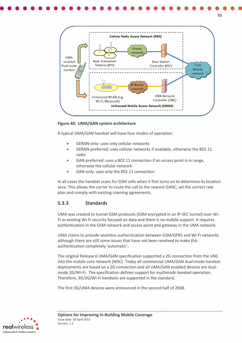
86
Options for Improving In-Building Mobile Coverage Issue date: 18 April 2013 Version: 1.2
Figure 40: UMA/GAN system architecture
A typical UMA/GAN handset will have four modes of operation:
GERAN-only: uses only cellular networks
GERAN-preferred: uses cellular networks if available, otherwise the 802.11 radio
GAN-preferred: uses a 802.11 connection if an access point is in range, otherwise the cellular network
GAN-only: uses only the 802.11 connection
In all cases the handset scans for GSM cells when it first turns on to determine its location area. This allows the carrier to route the call to the nearest GANC, set the correct rate plan and comply with existing roaming agreements.
5.3.3 Standards
UMA was created to tunnel GSM protocols (GSM encrypted in an IP-SEC tunnel) over Wi-Fi as existing Wi-Fi security focused on data and there is no mobile support. It requires authentication in the GSM network and access point and gateway in the UMA network.
UMA claims to provide seamless authentication between GSM/GPRS and Wi-Fi networks although there are still some issues that have not been resolved to make this authentication completely ‘automatic’.
The original Release 6 UMA/GAN specification supported a 2G connection from the UNC into the mobile core network (MSC). Today all commercial UMA/GAN dual-mode handset deployments are based on a 2G connection and all UMA/GAN enabled devices are dual-mode 2G/Wi-Fi. The specification defines support for multimode handset operation. Therefore, 3G/2G/Wi-Fi handsets are supported in the standard.
The first 3G/UMA devices were announced in the second half of 2008.

87
Options for Improving In-Building Mobile Coverage Issue date: 18 April 2013 Version: 1.2
In all cases the handset scans for GSM cells when it first turns on to determine its location area. This allows the carrier to route the call to the nearest GANC, set the correct rate plan and comply with existing roaming agreements.
At the end of 2007 the GAN specification was enhanced to support 3G (Iu) interfaces from the GANC to the mobile core network (MSC/GSN). This native 3G interface can be used for dual-mode handset as well as 3G femtocell service delivery. The GAN release 8 documentation describes these new capabilities.
5.3.4 Industry ecosystem
UMA started as proprietary to Kineto Wireless Technology [44]. Nowadays UMA is a 3GPP technology but it is not clear if any other vendors are promoting this technology.
Orange in the UK offers the feature “signal boost” (Figure 41) on some specific mobile device models to enable UMA; other operators internationally such as T-Mobile US and Rogers (Canada) but there has been little growth in take up over recent years. Although there is the benefit of increasing indoor coverage battery life is reduced considerably in many cases.
Figure 41: Signal boost feature, as offered by Orange UK
The major challenge that UMA/GAN faces is the fact that relatively few phones (e.g. not iPhones) support UMA and making it available for more phones can involve complex changes. However, more open operating systems (e.g. Android) can potentially be updated to support UMA by an end user download.

88
Options for Improving In-Building Mobile Coverage Issue date: 18 April 2013 Version: 1.2
There are ways to get around the fact that some mobile devices do not support the technology but still need further development to allow devices to support this feature without too much complexity, especially from a user's perspective.
5.3.5 Current availability and future evolution
UMA/GAN is offered by Orange in the UK as “Signal Boost”; T-Mobile USA offers it under the name “Wi-Fi Calling”; Rogers Wireless, in Canada calls it “Wi-Fi Calling Zone”. The last two operators make extensive use of this feature to enhance coverage for their customers in “difficult-to-reach” areas. In addition to these initiatives Telia Sonera in Sweden launched “Home Free” service based on UMA in 2006 and the service stopped in 2008. Cincinnati Bell is another operator in the USA that offers UMA through “Wi-Fi Fusion” and is still active in the US.
The first models were only equipped as dual-mode 2G/Wi-Fi. At the end of 2007 the GAN specification was enhanced to support 3G (Iu) interfaces from the GANC to the mobile core network (MSC/GSN). This native 3G interface can be used for dual-mode handset as well as 3G femtocell service delivery. The GAN release 8 documentation describes these new capabilities. Nowadays, 3G/2G/Wi-Fi handsets are supported in the standard and as from the second half of 2008 they are available in the market.
Blackberry devices support UMA/GAN and some Android devices can add UMA support via a user-installed application (self-UMA installations). However, UMA will not currently work on iPhones. Other devices that support UMA/GAN include [45]:
HTC - Touch 3G, T-Mobile Shadow 2009, T-Mobile myTouch 4G (sometimes called the myTouch HD),T-Mobile G2 (as of build 1.22.531.8 OTA update), Desire S, Wildfire S, Sensation 4G, Amaze 4G
LG - KE 520, KF 757 (3G), GT505, Optimus One, LG Optimus Me
Nokia - 6300i, 6301, 6301b, 6086, 6136, 7510, E73 Mode, E5, C7 Astound
Samsung - SGH-T339, SGH-T409, SGH-T709, SGH-T739 (Katalyst), T336, P250, P260, P270 (3G), T-Mobile's Galaxy SII SGH-T989, Orange Galaxy SII with NFC (GT-i9100P)
Sagem - my419X
BlackBerry - Curve 8320, 8520, 8820, Curve 8900, Pearl 8120 and 8220, Bold 9700, Bold 9780, Torch 9800, Blackberry 9105, 9300, Blackberry Bold 9900 with OS 7.1
Sony Ericsson - G705u (3G)
Motorola - DEFY
Linksys WRT54G series#WRT54G-TM Router
Westell - UltraVoice UMA Terminal Adapter with Router
UMA Today [46] is an international consortium of companies joined together to lead the adoption of 3GPP UMA technology around the world. UMA Today publishes the UMA Today Magazine hosts Webinars, sends news alerts to a subscription list and is involved in other industry activity to promote UMA technology.
To date not much research or newer developments are foreseen for UMA technology. UMA is not implemented in Asia, Australia, Africa and some European countries.

89
Options for Improving In-Building Mobile Coverage Issue date: 18 April 2013 Version: 1.2
5.3.6 Environmental impact
Using UMA/GAN on a mobile requires the Wi-Fi module to be enabled. This in turn drains the battery faster for standard mobiles and reduces both the talk time and standby time when compared to disabling UMA/GAN (and in turn Wi-Fi). For recent models of smartphones where Wi-Fi is normally turned ON this is not an issue.
Dual-band devices are required for UMA with a software-enabled activation – no extra hardware is needed.
Finally, as with any other cellular or wireless technology, UMA poses perceived health and safety concerns to users which are well-known and thus have led to further investigations throughout the years.
5.3.7 Operator deployment views
UMA/GAN is a Wi-Fi based network enabling a user to make calls using their handset. This technology uses a UNC (UMA Network Controller) as an interface with the mobile operators’ core network. Network operators may use this technology to augment their network coverage in particular at users home. In order to use this service the user must have a compatible handset and must register with the mobile network through the Wi-Fi service which the user has access so that the mobile network can recognise the Wi-Fi network and authenticate the calls. This may not provide the user with ubiquitous indoor access.
Currently the technology is limited to GSM although it has the support of 3GPP and a specification has been produced. Although it provides a cost effective means of delivering voice call capability to the network operators it is not gaining popularity as the service focus is shifting from voice to data. In the UK only Orange, part of Everything Everywhere, offers this as a service distinction in the early days of pre-UMTS service.
Positive
In general, for those countries that have deployed UMA as part of their service portfolio to customers, positive experiences have been documented and listed. An immediate one has to do with not having to erect expensive macro base stations to cover not spots but rather use low cost Wi-Fi access points to provide coverage thereby ensuring subscribers at home having much better coverage.
On the other hand UMA/GAN relieves congestion on the GSM or UMTS spectrum by removing common types of calls and routing them to the operator via the relatively low cost internet. UMA/GAN appears to make sense for network operators that also offer internet services since these operators can leverage sales of one to promote the other and can bill both to each customer.
Finally, in terms of costs, the carrier does not always have to pay for much of the service; the party who provides the internet and Wi-Fi connection pays for a connection to the internet, effectively paying the expensive part of routing calls from the subscriber.

90
Options for Improving In-Building Mobile Coverage Issue date: 18 April 2013 Version: 1.2
Negative
As with other technologies UMA has its downsides which have greatly affected the adoption of this technology by more operators and countries worldwide. For instance, subscribers must upgrade to Wi-Fi/UMA enabled handsets to take advantage of the service – it is not as simple as using a standard handset and performing a software upgrade. Also, some setup may be required to provide connection settings – such as authentication details – before advantages may be experienced. This may take time for subscribers and require additional support to be provided by the operator. The costs of support may be far more than the wireless phone company: network administrators may be asked to help a user enter appropriate settings into a phone.
From a quality-of-service perspective calls may be more prone to disconnect when the handset goes from Wi-Fi to the standard wireless service and vice versa as the handset moves in or out of the Wi-Fi range. The impact of this may vary depending on which handset is used.
The phones that support multiple signals (both the UMA/Wi-Fi and the type of signal used by the provider's towers) may be more expensive, particularly to manufacture, due to additional circuitry/components required.
Finally some security issues are raised. UMA uses the resources of the network providing the Wi-Fi signal and any indirect network that is then utilised when that network is used. This uses a considerable amount of bandwidth which is inefficient. Some types of network traffic e.g. DNS and IPsec-encrypted, need to be permitted by the network so a decision to support this may impose some requirements regarding the network's security (firewall) rules.
5.3.8 Assessment against Ofcom’s criteria
Study requirement Score Comments
Current status, take up and availability
UMA devices are losing popularity nowadays. Users need to replace their existing handsets.
Openness Only single operator and for GSM.
Authentication and handover
Not resolved and needs manual authentication and ‘signal boost’ feature turned on like this
Security GSM encryption guarantees good security.
Impact on the macro Data can be offloaded significantly.
Uplink or downlink constraint
No uplink / downlink imbalance issues
Current and future spectrum
Same situation as for carrier Wi-Fi and self-provided Wi-Fi, with newer bands being investigated.
Environmental impact Battery life may be an issue when ‘signal boost’ is turned on
Future evolution UMA is not being pushed by industry anymore, so concerns of not having support in the near future
Scalability Same as for carrier and self-provided Wi-Fi
Upgradeability Very limited as UMA newer standards are not in place anymore
Table 19: Assessment of UMA against study requirements

91
Options for Improving In-Building Mobile Coverage Issue date: 18 April 2013 Version: 1.2
6. Appendix E – Detailed discussion of dedicated in-building solutions currently available – Cellular small cell related solutions
Currently available dedicated in-building solutions include:
Wi-Fi including: o Self-provided Wi-Fi o UMA/GAN o Carrier Wi-Fi
Cellular small cell solutions including: o Femtocells o Picocells (and enterprise femtocells)
Traditional approaches to indoor coverage including: o Repeaters (and more recently intelligent repeaters) o DAS (and its evolution towards distributed basestations)
This appendix describes in detail cellular small cell solutions to improving indoor coverage identified above to support discussions in chapter 6 of the report main body. These solutions are assessed against the requirements of the indoor consumer types described in appendix A and also Ofcom’s initial study requirements.
6.1 Femtocells
A femtocell is a small box, similar to a Wi-Fi access point, which when plugged into a consumer’s power and broadband connection provides improved mobile service in the home and small office environments where poor or no mobile signal level previously existed. The conceptual layout of a femtocell deployment is shown in Figure 42. The femtocell accesses the operator’s network via the user’s broadband connection and then transmits mobile signals to and receives mobile signals from the mobile devices of users in the home. It is effectively acting as a mini basestation and setting up a localised mobile phone network in the home.
Figure 42: Overview of how a femtocell works (Source: Small Cell Forum)

92
Options for Improving In-Building Mobile Coverage Issue date: 18 April 2013 Version: 1.2
6.1.1 Consumer proposition
Femtocells are not currently available to buy freely like Wi-Fi access points but must be obtained by the consumer directly from operators. All UK operators offer femtocells although EE only support business customers for femtocells currently and Three only offer these to customers with poor coverage. The femtocell usually comes at a modest one off cost (sub £100) or for an increase in monthly contract rate.
Figure 43: Femtocells as available from all UK operators currently (Products shown from EE, O2, Vodafone and H3G)
Once connected to power and a broadband connection the user usually needs to register the femtocell with their operator online and then wait for the operator to enable their access point (which happens automatically over the broadband connection but can take several hours).
Femtocells offered by UK operators today support 3G only and so to make use of them the user must have a 3G phone. The phone number of all phones permitted to use the femtocell must also be registered with the operator but can be updated online at the request of the user to add new phone numbers. Femtocells will currently only work for phones with the same operator and so users need to make sure that everyone in their home uses the same operator to make best use of it.
Once installed the indoor service improvements seen by consumers from femtocells will include:
Better availability and quality of cellular voice, SMS and data services in the building
Better cellular data rates
Improved mobile phone battery life
Simple to set up, with little or no configuration required
Potentially reduced mobile costs if operators choose to bill consumers for femtocell traffic differently to their usual monthly data allowance. While this

93
Options for Improving In-Building Mobile Coverage Issue date: 18 April 2013 Version: 1.2
has not been seen in the UK yet, Vodafone in Greece have started giving their users free data usage in some public buildings where they use femtocells. There is no reason why this could not be repeated in the UK market for home users.
Potentially specialised indoor services might be offered from the operator via femtocells. These are not yet widely available but ideas being discussed include parents being able to monitor when their children are in the house or identifying when unknown “guests” enter the home (provided they are carrying a mobile phone).
Limitations of femtocells for consumers to note are:
The consumer must provide (and pay for) an adequate broadband connection to allow the femtocell work
The user must have a 3G handset
Only one operator is supported per femtocell which may restrict choice of operators in a household if only one femtocell is used and service from other operators is also poor. However, it would be straightforward to obtain and install multiple femtocells if needed and there should not be any interference issues as these femtocells will likely be deployed on carriers specific to each operator.
The user will need to register mobile phones with the operator to allow them to make use of the femtocell and so cannot automatically add users to the femtocell themselves for infrequent guests for example.
Femtocells are designed to target homes and small offices and this is reflected by the summary of how femtocells fit across different building types shown in Table 20.
Home user Small office / SME Large multi storey office
Public buildings / areas
Femtocells are targeted at home and small office users so will provide service improvements across most house sizes.
As for home user but in the case of larger SMR premises a femtocell may not be able to cover all areas or capacity may be too limited (usually support 4 to 16 concurrent users in current products). At the larger end of this building category picocells would be more appropriate.
Femtocells too low power and hence range for larger buidlings.
As for large multi storey offices.
Table 20: Fit of femtocells across building types
6.1.2 Concept in more detail
A femtocell is a low power access point installed in a home or small office environment that provides localised cellular coverage backhauled via the user’s broadband connection.

94
Options for Improving In-Building Mobile Coverage Issue date: 18 April 2013 Version: 1.2
In a UMTS network a femtocell, termed a Home Node B (HNB), effectively takes the place of a Node B within the network and provides a low powered UMTS air interfaces to mobile devices within a limited range.
The architecture for incorporating femtocells into existing UMTS networks is shown in Figure 44 The femtocell incorporates much of the functionality traditionally found in the radio network controller (RNC) but unlike a RNC does not have a direct connection into the operator’s core network. Instead the connections of multiple femtocells are concentrated by a HNB gateway which appears as a RNC to the core network. The interfaces between this HNB gateway and the femtocells or HNBs is known as the Iuh and is a femtocell specific variant of the Iu interface that is normally found between the RNC and core network in UMTS networks.
Crucially femtocell networks also include a security gateway to authenticate the femtocell and secure the connection between the HNB gateway and femtocell as this is provided over a public broadband connection.
Figure 44: HNB and related network elements and interfaces included within a UTRAN alongside macrocell UTRAN elements with HNB specific interfaces highlighted [47]
6.1.3 Standards
Overview Since release 8 femtocells have been included in 3GPP standards. Figure 45 provides a summary of the areas in the technology independent femtocell reference architecture defined by the Small Cell Forum where 3GPP standards specifically for femtocells now exist. Encouragingly this now covers most of the network and main issues including:
RF aspects

95
Options for Improving In-Building Mobile Coverage Issue date: 18 April 2013 Version: 1.2
The supporting architecture to integrate femtocells into existing networks including elements such as the HNB gateway, security gateway and HNB management system and interfaces between these and the femtocell
Security aspects of femtocells
Operation and maintenance procedures and interfaces for femtocells
Figure 45: Mapping of 3GPP standards to the Small Cell Forum reference architecture for femtocells [47]
The overall progression of femtocells across various 3GPP releases can be summarised as follows [47]:
Release 8 included femtocell specific standards for the first time with major milestones including: o Updates to existing base station RF requirements and testing standards,
TS 24.104 [48] and TS 25.141 [49], in late 2008 to include a Home Base Station category of base station with revised maximum transmit power levels, relaxed oscillator accuracy, reduced test cases for lower speeds and fewer users, an increased receiver dynamic range and revised spectrum emission mask.
o The definition of a HNB reference architecture in TS 25.467 [50] completed in December 2008 which included concepts from Small Cell Forum such as using a HNB-GW to concentrate traffic from multiple femtocells.
o The definition of a standard femtocell specific interface between the HNB and HNB-GW called the Iuh in TS 25.468 [51] and TS 25.469 [52].
o The definition of OAM messaging and data models specific to HNBs which drew upon existing standards within the Broadband Forum and a newly developed femtocell specific model which the Small Cell Forum and Broadband Forum developed together.
Release 9 included updates related to HNB mobility and limited recommendations on interference management for femtocells based largely on
96
Options for Improving In-Building Mobile Coverage Issue date: 18 April 2013 Version: 1.2
power control. The main new femtocell specific content in release 9 includes work on the security requirements of HNBs in TS 33.820 [53].
Release 10 brought support for Local IP Access (LIPA) as a means for diverting some femtocell traffic locally within the home where distribution over the core network is unnecessary and enhancements to HNB mobility management which included the definition of the so called Iurh interface as a logical direct interface between HNBs.
Release 11 has included work to expand TS 33.820 to include the security additions needed when inter HNB and HNB to RNC connectivity is permitted together with a further study item on enhanced mobility for HNBs.
Release 12 only foresees RAN-level work on 3G HNB as being work on cell reselection involving CSG cells whilst the UE is in CELL_FACH state. Further work is anticipated on mobility under cells when LIPA or SIPTO (Selected IP Traffic Offload) is deployed in the Local Network and Broadband Access Interworking where Broadband Provider and Mobile Service Provider may cooperate on policy control and Quality of Service.
Alongside these standards there has been a large amount of interoperability testing to prove these standards in practice and feedback any limitations found.
Security Crucially the 3GPP standards for femtocells now include security specifications in the form of TS 33.320 which includes security countermeasures which broadly cover:
Physical security of the femtocell and the use of trusted environments
Authentication of the femtocell with other femtocell related network elements prior to any communications
Use of IPsec tunnelling to establish secure communications to the femtocell
Physical security of femtocells is a concern raised in 3GPP standards but the exact implementation of tamper resistant mechanisms is left to the vendor. This is an area of growing industry best practice but as yet is not well established. 3GPP does, however, specify the use of trusted environments on femtocells for storing sensitive information such as authentication information. The Trusted Environment (TrE) is described as a logical entity of the HNB which provides a trustworthy environment for sensitive functions and data. Its contents should at all times remain unknown and invisible to external entities.
Authentication of femtocells includes the use of the security gateway to authenticate the femtocell access point before communications are established with any other network elements. This is done via authentications procedures using IKEv2 certificates. The security gateway then uses IPsec tunnelling to establish a secure connection to the femtocell which all related network elements can use.
However, some of our stakeholder discussions have highlighted that currently vendors generate and digitally sign their own certificates in a closed secret key system to authenticate the identity of femtocells. This means that the identity of femtocells from various vendors can only be verified by security gateways also within this closed secret key system i.e. those from either the same vendor as the femtocell or those with an interoperability agreement with the femtocell vendor. This secret key system is not thought to be expandable particularly given the large volume of femtocells forecast and

97
Options for Improving In-Building Mobile Coverage Issue date: 18 April 2013 Version: 1.2
centralised Public Key Infrastructure (PKI) with a central certification authority for digitally signing authentication certificates is thought to be required in the long term. This centralised PKI system would be similar to that used to authenticate web browser sessions currently.
Note that a similar authentication issue arises in LTE networks due to the eNode B containing more network intelligence than a traditional Node B in UMTS networks and being connected to the core network potentially via an IP based connection rather than the dedicated backhaul link assumed in UMTS networks. Therefore this issue of a centralised certificates authority and PKI system for cellular systems is anticipated to be resolved over time in LTE systems.
From an implementation of security standards point of view, operators do need to have all 3GPP home UTRAN elements of the HNB-GW, HMS and security gateway deployed in their network to fully support large scale femtocell deployments. This may be expensive and time consuming to do.
It should be noted that the existence of security standards does not ensure that these standards will be implemented by vendors and operators following best practice security approaches. For example work at Technishe Universität Berlin, has revealed a series of vulnerabilities in a femtocell from Ubiquisys that was provided by the French operator SFR. The group was able to demonstrate downloading their own firmware to the femtocell, capturing other UE traffic on the femtocell and accessing other femtocells in the network [54]. They also highlight that this issue is not unique to the femtocell tested by them and point to publicly available sources on hacking the Vodafone Sure Signal unit and Samsung femtocell.
Our discussions with industry stakeholders have also indicated that recent publicity around the hacking of femtocells [55] has been as a result of weak implementation of security techniques, such as leaving default passwords set up, weak passwords or leaving configuration web interfaces active, rather than a direct weakness in the security mechanisms prescribed by the 3GPP standards. This highlights the importance for certification of access point devices that are located in on consumer premises.
Handover In terms of handover and mobility issues for femtocells these are areas of activity in the standards. Small cells largely follow the same mobility procedures as macrocells but with the addition of small cell specific interfaces including the Iurh to assist in this. Generally handover and radio planning becomes more difficult for operators as there are more cells to consider in neighbour lists, handover rules etc.
Handover is not different from a user perspective (happens automatically) but the operator settings may mean dropped calls due to hand in problems with femtocells.
This is an area far from resolved in the industry and an area to be closely monitored.
6.1.4 Industry ecosystem
There are currently a large number of femtocell vendors with a good balance amongst these between new start-ups and established basestation manufacturers. The addition of femtocell specific standards in 3GPP means that the architecture and interfaces for

98
Options for Improving In-Building Mobile Coverage Issue date: 18 April 2013 Version: 1.2
femtocells are now clearly defined which leaves the way open for new entrant vendors. Figure 46 illustrates the range of femtocells currently available.
Initiatives such as Small Cell Application Platform Interface (SCAPI) within the Small Cell Forum have also defined interfaces between modules within femtocell access points which creates conditions for a more open ecosystem for chipset and software providers.
Figure 46: Range of femtocell access points currently available
A key point to note with the femtocell ecosystem is that femtocells are provided directly by operators and currently only support single operator solutions. This means that all users in a household need to be on the same operator to make use of the femtocell. This is sold as a benefit of femtocells to operators in that it reduces churn but is clearly a disadvantage for the consumer as it limits their choice of operator and makes switching operators more difficult.
Technically, the production of a multi operator femtocell supporting multiple bands in the low cost form factor of a femtocell would be challenging but not impossible. However, it is highly unlikely that we will see multi operator femtocells in the near future due to the commercial drivers to keep femtocells as single operator solutions and cost effective. Operators also argue the point that some have invested heavily in the aesthetics of their femtocell solutions (for example the Vodafone “femtoplug” product) which gives them a competitive advantage which they are not willing to share.
It is worth noting that while single operator femtocells make switching operators more difficult this is not prohibitively so. The penalty for moving operators will likely be the modest cost of a new femtocell access point and some setup time on the consumers part to register the femtocell and authorise phones. It is also worth noting that there are some similarities here with the history of DSL modems which were originally provided by ISPs but now consumers can buy these directly.
6.1.5 Current availability and future evolution
Current and future availability Residential and enterprise femtocell indoor deployments are rapidly increasing in take up. The December 2012 Small Cell Forum Informa market status update [56]indicates that between October and November 2012 small cells reached a crucial milestone when the number of small cells deployed worldwide surpassed that of macrocells at 6 million against 5.9 million. The same report claims 46 commercial small cell services were available worldwide (see Figure 47 for some of these). Interestingly this now includes femtocell offerings from all UK operators but, as highlighted in section 6.1.1, EE only

99
Options for Improving In-Building Mobile Coverage Issue date: 18 April 2013 Version: 1.2
support business customers for femtocells currently and Three only offer these to customers with poor coverage.
In terms of the future for femtocells the Informa report suggests strong growth in shipments of femtocells with the number deployed likely to grow to over 80 million by 2016.
Figure 47: Some of the operators with small cell services deployed
Future evolution In terms of the future of femtocell technologies current generation products are focused on 3G but LTE products are starting to emerge. The SON features of LTE lend themselves to femtocells and to a large extent have been used already in 3G femtocells. This may mean that as networks evolve to LTE that there will be a growing demand for femtocells as their integration into networks will likely become easier.
Another future trend is that while early femtocells have been very much coverage dominated there is an expectation that they will tackle capacity and new services in the future. This may provide the motivation for operators to encourage femtocells more than in the past.
A question for the future of femtocells is the issue of scalability. Femtocells are consumer rather than operator deployed so it is difficult to guarantee minimal interference in dense deployments of femtocells such as may be found in a block of flats. However, this case study of a block of flats has been widely studied with the general consensus that careful use of hybrid or open access femtocells will be able to overcome these interference issues.
It is also worth noting that femtocells naturally incorporate SON features and so lend themselves to being a very scalable solution. While initial deployments have been arguably quite manual on the operator’s part it is expected that there will be improvements in this area as operators increasingly invest in the infrastructure to incorporate femtocells more fully into their networks with and automate management and billing functions.

100
Options for Improving In-Building Mobile Coverage Issue date: 18 April 2013 Version: 1.2
Current and future spectrum requirements On the question of current and future spectrum requirements for femtocells, this should largely track the spectrum requirements of macrocells for shared spectrum deployments. However, the ability for operators to deploy femtocells on a dedicated carrier would overcome many interference concerns and likely strengthen the case for increased deployment of femtocells. Ideally operators would have an existing “spare” carrier for femtocells but the current spectrum situation in the UK for 3G is uneven in this respect across operators with some having three or more 3G carriers available while others only have two. A shared access low power band, such as that which was proposed as part of the recent 2.6GHz auction, would help to level this situation across operators and also remove barriers to new entrant localised operators focusing on perhaps indoor services. Opening such new bands to new entrants would require careful consideration such as the appropriateness of a coverage obligation or specifying roaming across existing operators to ensure that the barriers to entry were not too high.
6.1.6 Environmental impact
Generally femtocells are low power devices and product advances mean that their power consumption is fast reducing towards that of Wi-Fi access points. There is much debate surrounding whether the widespread deployment of many low power femtocells compared with few high power macrocells could have a negative impact on overall power consumption across the cellular network. However, it is worth noting that the power consumption of femtocells comes with the added benefit of improved service levels and so power consumption needs to be viewed in term of energy per capacity added. One such study performed on this basis has found that networks with femtocells included have similar or slightly lower power consumption per unit of capacity to macro only networks [57].
Note that femtocells are also subject to the EC code of conduct on power consumption for broadband devices which stipulates a maximum “on state” level of 9W. Currently available femtocell products easily meet this requirement [58]. Note however, that there is some variation in power consumption amongst vendors with 1st generation products from new entrant vendors being higher in power consumption than more mature solutions from more established vendors. A final point on the power consumption of femtocells is that the incremental power consumption of femtocells may be low if incorporated into products that users have in their homes anyway such as their broadband router.
6.1.7 Operator deployment views
As highlighted in Figure 44, a femtocell requires a series of other network elements to be installed for its management and interface to the operators’ core network. The HNB gateway can manage a large volume of femtocell radio nodes, in the order of tens of thousands. Although the femtocell radio node itself is inexpensive, this gateway is a high cost item which pushes up the start-up cost of a femtocell network for operators. Until this business case was justified and the competition environment demanded its deployment, operators were therefore reluctant to venture into the femtocell business.
Operators deploying femtocells must embark on a very carefully planned deployment process with the required logistics to support this taking into consideration:

101
Options for Improving In-Building Mobile Coverage Issue date: 18 April 2013 Version: 1.2
(a) The femtocell must be a customer self-installed unit. The operators cannot afford a dedicated team for its installation due to the potential high volume.
(b) The femtocell needs to be pre-configured for some of the operational parameters including the operating frequency which in some cases could be difficult due to possible interference from/to the macrocells although network listen functions in femtocells address this to a certain extent.
(c) The femtocell is a portable unit. For licencing reasons, it therefore needs to be registered for the specific user at a specific address. Features also need to be incorporated to deter the movement of the femtocell to other locations.
(d) Set up of logistics support for the dispatch, return and swap of faulty femtocell units.
(e) Provision of customer service support on problems and enquires related to femtocells. All these require proper training.
(f) The set-up of a management system to support femtocell operations.
Impact on the macrocell network The deployment of femtocells should bring the benefit of offloading some of the existing macrocell traffic. Work within the Small Cell Forum indicates that a small proportion of users generate the majority of traffic on cellular networks and that the majority of these are indoor users [59]. This study quotes white papers from both Ericsson and NSN which indicate that 20% of sites carry more than 50% of the network load and that 50% of traffic is carried by 15% of cells respectively. Deploying femtocells for these high traffic indoor users means that this traffic is no longer seen by the macrocellular network or is “offloaded” to the femtocell layer of the network.
Although femtocells provide a traffic offload benefit, it is expected that its main use will still be in sub-urban areas, probably mostly at home or SoHo where existing coverage from the macrocells is poor. Operators will still be relying on their own deployed cells in the Central Business District (CBD) area. These might be in the form of rooftop macrocells, small cells or dedicated indoor picocells.
Also removing these hard to reach indoor users from the macro network will mean that macrocell resources can be given to users in better SNR conditions which will result in an improvement in service levels from the macrocell. An additional benefit of offloading users to femtocells is that femtocells operate over short ranges and so do not require low frequency carriers. The traffic offloaded to femtocells may therefore also save the operator in terms of the volume of low frequency spectrum needed assuming a high frequency carrier is available to support the indoor femtocell network.
There may be a negative impact on the macrocell in terms of interference from femtocells in shared carrier deployments. This has been an area of much activity and appeared constantly in the 3GPP initial studies into the requirements of femtocells [60][61]. Current femtocells incorporate interference mitigation techniques such as power control and network listen which brings interference down to acceptable levels in the vast majority of cases. There are some corner case interference issues such as a macro cell UE coming close to a closed access femtocell and experiencing a “deadzone” in coverage due to uplink interference from the femtocell. Several techniques have been suggested for

102
Options for Improving In-Building Mobile Coverage Issue date: 18 April 2013 Version: 1.2
addressing them but they are not yet trialled and tested [62]. However, it is worth noting that interference is likely to be more of an issue to the macrocell from outdoor small cells than it would be from indoor femtocells.
To quantify the balance between these positive and negative impacts on the macrocell, the Small Cell Forum have conducted a study of 3G small cells in outdoor environments [63] which demonstrates interference management techniques that allow small cells and macrocells to coexist in the same frequencies without causing undue interference. Simulations within this study show that that even with conservative deployments, small cells could offload the majority of subscribers in busy areas, reducing network load and improving user experience – see Figure 48 and Figure 49. While these results are for outdoor small cells the idea that the deployment of small cells will have a net overall positive impact on the total user experience of the network is applicable to femtocells too.
Figure 48: Simulation results of expected capacity offload provided by small cells (Source: Small Cell Forum)
Figure 49: Simulated improvement in median throughputs experienced by all users and macrocell users through the inclusion of small cells (Source: Small Cell Forum)
6.1.8 Assessment against Ofcom’s criteria
Table 21 provides a summary of how femtocells score against the original project requirements set out by Ofcom. In the case of each requirement we give a red, amber or
21%
56%
75%
0%
10%
20%
30%
40%
50%
60%
70%
80%
1 4 10
Small cells per macro
% t
raff
ic o
fflo
ade
d
58%
315%
523%
31%138%
246%
0%
200%
400%
600%
1 4 10
All Users
Macro Users
% increase in median throughput over macrocellsalone
Small cells per macrocell

103
Options for Improving In-Building Mobile Coverage Issue date: 18 April 2013 Version: 1.2
green score depending on whether there are any major blocking issues, minor issues or no issues against each requirement respectively.
Study requirement Score Comments
Current status, take up and availability
Femtocells now offered by all UK operators.
Deployments in the UK are at an early stage but US networks already at significant volumes.
Operators universally acknowledge the importance of small cells in the future of their networks and market forecasts predict extremely large volumes of femtocells shipped.
Openness 3GPP standards for small cells exist with standard interfaces so no barriers to new vendors obvious. Already many femtocell access point vendors for operators to choose from.
Today’s femtocells are single operator and likely to remain so for commercial reasons. However, they are low cost and available from all UK operators so consumer ability to switch operators is not perceived to be an obstacle. In the case where a single household uses femtocells from multiple operators there should not be any interference issues as these femtocells will likely be deployed on carriers specific to each operator.
Authentication and handover
Authentication occurs as defined by 3GPP home node B security procedures but handover in small cells has some issues and is an area of activity.
Authentication currently limited by certificates to verify the identity of the femtocell to the network being digitally signed by vendors which means they may only work with particular security gateways. A central authority for signing authentication certificates and a centralised Public Key Infrastructure (PKI) similar to that used to authenticate web browser sessions is required long term.
Security Uses 3GPP existing security model for small cells. Potential concern over physical security of access points but industry best practice being established in this area amongst vendors. General gap of ensuring security mechanisms from standards are implemented robustly which is likely to evolve with time but could benefit from Ofcom input to encourage establishment of best practices.
Will not be able to support 999 calls in a power cut
Some issues with femtocells being used overseas which Ofcom may be able to work with operators to tighten up on.
Impact on the macro Studies show a net overall improvement in service across both macro and small cell is likely. Some concerns over interference in corner cases but operators can control via network settings.
Uplink or downlink constraint
No uplink / downlink imbalance issues
Current and future spectrum
Same spectrum requirements as macrocell networks. The case for a dedicated carrier is not as strong as in outdoor small cells but would still be beneficial.

104
Options for Improving In-Building Mobile Coverage Issue date: 18 April 2013 Version: 1.2
Study requirement Score Comments
Environmental impact Power consumption likely much less than macros but cumulative power of many femtocells vs. macrocells is an area for active debate. Power consumption largely expected to be similar to Wi-Fi access points.
ICNIRP compliance required so no real technical health concerns but public perception may be an issue.
Future evolution LTE femtocells are emerging.
Likely that femtocells will gather momentum under LTE due to SON features making their incorporation into networks easier.
Scalability SON designed to manage large networks so there should be no scalability concern. AT&T claim to have 40k small cells deployed already with no issues. Vodafone in the UK are estimated to have more than 100k femtocells deployed already too.
Upgradeability Low cost means that products are ASIC based and so major upgrades like an update to include LTE will need a new access point. However, these are low cost and easy to install.
Table 21: Summary of femtocells against the study requirements
6.2 Picocells
A picocell is a small basestation which is part of an operator’s cellular network and is installed in buildings to improve the cellular service levels there. Picocells are designed to be deployed in medium enterprise environments and public buildings. Currently operators in the UK will send an engineer (usually a contractor) to the building to carry out a survey and determine what (or if) a picocell deployment will work for that building. The costs for this survey, which are generally modest, may be borne by the operator if the customer is theirs or by the occupier of the building if they are not a corporate customer. The units themselves are generally deployed by the building occupiers, using guidelines supplied by the operator, although the operators will deploy them in certain circumstances.
Figure 50: Some examples of picocell products available (Products shown from ip.Access and Ubiquisys)
6.2.1 Consumer proposition
The end user in buildings where picocells are deployed will see an improvement in their existing cellular service level without any action on their part. Picocells will work with

105
Options for Improving In-Building Mobile Coverage Issue date: 18 April 2013 Version: 1.2
existing cellular mobile devices and are available to support GSM, UMTS and even LTE so there is no need for the consumer to invest in a new handset to benefit from picocells.
Building and business owners and their IT departments will, however, need to get involved in the installation of the picocell access point or network. Depending on the complexity of the network installed some disruption may be experienced during the installation process but this would be less than for a DAS deployment.
Similarly to femtocells, once installed the indoor service improvements seen by consumers from picocells will include:
Better availability and quality of cellular voice, SMS and data services in the building
Better cellular data rates
Improved mobile phone battery life
Potentially reduced mobile costs if operators choose to bill consumers for picocell traffic differently to their usual monthly data allowance. While this has not been seen in the UK yet, Vodafone in Greece have started giving their users free data usage in some public buildings where they use femtocells. There is no reason why this idea could not be transferred to the enterprise market to give corporate customers with picocells installations improved contract rates.
Potentially specialised indoor services might be offered from the operator via picocells but these are not yet widely available.
Limitations of picocells for consumers and building owners to note are:
The building owner or business will likely have to provide (and pay for) a broadband connection to make the picocells solution work.
Only one operator is supported per picocell which may limit the range of operators supported in a building or require multiple picocells deployments. However, this is less likely to be an issue for a business with a contract for all employees with the same operator than for a home user.
Capacity may be a limitation depending on the backhaul and intelligence of the picocells network in managing users between cells.
The building owner or business will have to pay some or all of the cost of the survey and picocells, together with the installation costs, unless they are a corporate user on the operators network
Home user Small office / SME Large multi storey office
Public buildings / areas
Femtocell is a lower cost better alternative to a picocells for home users.
In larger buildings in this category or higher buildings with a high number of users where femtocells are too limited, picocells offer a good solution and have been designed to target SMEs.
Picocells are designed for enterprise environments and can be deployed as a network to cover large multi storey buildings at a reduced cost compared to bespoke DAS solutions.
May fit some public buildings but likely that capacity will become an issue in venues with very high numbers and densities of users.
Table 22: Fit of picocells across building types

106
Options for Improving In-Building Mobile Coverage Issue date: 18 April 2013 Version: 1.2
6.2.2 Concept in more detail
Picocells (also known as enterprise femtocells) are a medium powered, reduced capacity, low cost basestation which can be integrated into an operators network via gateways so that they appear as a normal macrocell basestation to the core network. They tend to target medium sized enterprises and public spaces.
Picocells have evolved over a number of generations:
1st generation – The concept of picocells has existed for a long time in the form of cut down macrocells for some large buildings. However, these were costly and too expensive for most deployments. Usually these solutions needed to be paired with a DAS as it was too costly to deploy multiple picocells in big buildings.
2nd generation -Picocell products started to emerge from companies such as ipAccess which were the same as femtocells in concept (i.e. low cost basestations) but with higher power and capacity. These have been deployed in various parts of the world. Originally these were largely 2G products but more recently 3G equivalents have become available. These products had modest success as they did not include intelligence in the basestation and required operator management which raised scalability questions.
3rd generation – Picocells now incorporate many of the learnings of femtocells including: o Producing low cost basestations based on consumer electronics similar to
handsets rather than costly macrocell basestations o Incorporating 3GPP standards for gateways and interfaces from large
volumes of small cells to the core network o Incorporating 3GPP standards for handover and interfaces between small
cells o Incorporating 3GPP standards for consumer deployed access point
security
There is still some debate over the best architecture to adopt for picocells and their integration into existing networks. This leads to a range of picocell solutions currently being available which vary in the architecture they support. Some picocells are enhanced femtocell products that support a higher number of users and cover a bigger area. These simply require power and a broadband connection as was the case with femtocells to be installed. These networks tend not to provide soft handover but it is generally agreed that hard handover in call needs to be supported in picocells.
More complex architectures include having a network controller also included at the building to support a network of picocells and importantly manage varying levels of soft and hard handover between these. Other picocells products go beyond offering purely cellular enterprise networks and also can include Wi-Fi support.
IPAccess’s nanoBTS for GSM is probably one of the most well-known picocell products and has been deployed by one UK operator for their SME and VIP customers, and is used in the dealer shops where GSM coverage is inadequate. It is used more extensively in the USA, in the order of thousands.

107
Options for Improving In-Building Mobile Coverage Issue date: 18 April 2013 Version: 1.2
The product is based on the GSM architecture which has its own BSC normally located in the same switch centre where the MSC is located. DSL is used for the connection between the BSC and the remote base stations. The BSC had a small capacity of about 100 base stations initially but newer models are capable of about 200 base station connections.
The nanoBTS has to be configured in a similar way to a normal 2G base station for which frequency planning and other configuration parameters such as neighbour list will have to be generated for a GSM call to be handled properly. Configuration for a new BSC is also required for the core network to recognise its existence.
Another picocells product example is available from SpiderCloud. The 3G variant of this product has an architecture which is similar to that for the UTRA but with an equivalent RNC installed at the customer’s premises. The equivalent RNC is a SCSN (SmartCloud Switch Node) which performs a subset of RNC functions such as managing the mobility within the SpiderCloud network and to the external macrocell. It also has a connection to its own enterprise server providing intranet services. Up to 75 radio nodes (SCRN) can be connected to the SCSN. The connection between SCRN and SCSN is via Cat 5/6 cable up to a range of 90m. DSL is used for the connection between SCSN and the operator’s core network.
6.2.3 Standards
Picocells adopt and follow largely the same set of 3GPP standards as already described for femtocells in section 6.1.3. This 3GPP suite of small cell specific standards includes:
Revised RF standards for Home and Local Basestations
Authentication and security procedures for small cells.
Investigations into handover for small cells and the definition of interfaces between small cells and towards RNCs to support handover.
Definition of operation and maintenance procedures for small cells
Definition of a reference architecture for integrating small cells with an operators network which includes a gateway for concentrating the connections of multiple small cells into the core network and a security gateway to set up secure connections between the small cells and operator’s main network.
The Small Cell Forum has also issued guidelines on enterprise small cell deployments to aid companies aiming to deploy these themselves [66]. These provide simple siting guidelines and some guidance on straightforward measurements of existing macrocells for “self-deploying” building-owners or companies to follow for picocells.
6.2.4 Industry ecosystem
The existence of small cell specific 3GPP standards means that multiple operators can design picocells products against these. While there is still some debate on the best architecture for picocells this is more an area for differentiation between vendors rather than a barrier to new vendors entering this market. The supply chain for picocells is open to new vendors as main interfaces are defined within 3GPP.
108
Options for Improving In-Building Mobile Coverage Issue date: 18 April 2013 Version: 1.2
There are currently two main established vendors for 3G picocells: ipAccess and Ubiquisys. However, new entrants to this market include Spider Cloud, Alcatel Lucent and NSN.
Spider Cloud’s 3G enterprise solution has been available since 2012 and they have recently added LTE products to their range. They claim to offer the only enterprise solution to support soft handovers and connection of large volumes of radio nodes (up to 100) [64]. They also claim to offer a highly agile scalable enterprise solution that can be deployed with the capacity to cover 2,000 to 3,000 people in 2 to 3 days. Notably they have been working with Vodafone over the last four years and NEC since June 2012 to ensure that their solution works with NEC small cell gateways and to test Iuh interoperability.
Alcatel Lucent and NSN “cloud RAN” solutions for indoor environments include the option of a centralised controller connected to multiple picocells access points which is another approach to picocell based enterprise solutions. These systems intelligently distribute capacity across a network dynamically depending on where it is needed and can track traffic movements to different locations at different times of the day. However, as cloud RAN systems tend to put most of the network intelligence at the central basestation or controller rather than at the individual access points there are concerns a local controller may be needed in places to manage security and mobility of large densities of users in localised areas.
Existing picocells products are single operator products and it is likely that including multiple operators in this low cost form factor would be challenging. It is therefore unlikely that multi operator picocells will be available in the short term. Also there are commercial incentives for operators to keep picocells as single operator devices as this means in enterprise deployments that a business customer will be less prone to change operators if it also means changing picocells.
Picocells represent a change in deployment model in that they tend to be deployed by building owners in medium sized enterprises or public areas rather than operators themselves. However, operators may still deploy them directly in in-building locations of particular interest to them. For example, Vodafone Greece has launched the world’s first location-based service driven by indoor picocells which white-lists traffic generated at particular indoor locations and provides their users with a data service in these locations that does not contribute to their data cap.
In terms of target deployments, picocells hit a sweet spot between short range low capacity femtocells and very expensive DAS installations and hence are ideally targeted at medium to large sized enterprises. Table 23 gives an indication of the potential business market for picocells in the UK based on the number of medium to large businesses reported, keeping in mind that a subset of these will suffer from poor in-building service levels.. However, this indicates that the volume of picocell solutions in the UK could be significant.

109
Options for Improving In-Building Mobile Coverage Issue date: 18 April 2013 Version: 1.2
Employees Businesses Percentage of total businesses
Percentage of total private employment
1-9 (Micro) 1,022,695 82.3% 19.2%
10-49 (Small) 177.950 14.3% 17.3%
50-249 (Medium) 29,750 2.4% 14.5%
250+ (Large) 6,455 0.5% 48.6% *Excludes sole proprietorships and partnerships comprising only the self-employed owner-manager(s) and
companies comprising only an employee director.
Table 23: Statistics on the size of UK business giving an indication of the potential size of the picocell business market if only really applicable to medium to large businesses [75]
6.2.5 Current availability and future evolution
Current and future availability 3G picocells products are widely available from vendors such as Ubiquisys, ipAccess, NSN, Alcatel Lucent and recently SpiderCloud. LTE products are also emerging from across these vendors but are not widely deployed yet.
According to the December 2012 Small Cell Forum Informa market update [56], 19 operators worldwide had deployed small cell deployments classed as enterprise or public solutions (which we understand to mean picocells). The same market update forecasts a steady growth for picocells although the volumes will be small compared to femtocells.
Picocell solution vendors such as Spider Cloud report increased levels of interest in trials with operators generally and are reported to have been working with Vodafone for the last four years [64]. This may be indicative that picocells deployments are likely to gain momentum in the near future.
Future evolution The natural evolution of picocells is towards LTE and LTE picocells are already emerging. The SON features of LTE inherently accommodate small cells more easily into existing networks. It is therefore likely that picocells will gain momentum as networks transition to LTE and small cells generally are easier to incorporate into the main macrocell network.
Interest and activity in this space indicates that enterprise indoor solutions, such as picocells, is a growing area and potentially one that will eventually take market share from DAS [74].
Current and future spectrum requirements As with femtocells, picocells should largely track the spectrum requirements of macrocells for shared spectrum deployments. However, the ability for operators to deploy picocells on a dedicated carrier would overcome many interference concerns and likely strengthen the case for the deployment of picocells.
As already discussed for femtocells, UK operators are currently unlikely to have a “spare” 3G carrier in existing licenced spectrum to dedicate to small cells and so a shared access low power band, such as that being proposed at 2.6GHz in the UK, might help to level this situation across operators, remove barriers to new entrant localised operators focusing on indoor enterprise services or indeed deployment by the enterprise directly without the need to engage with the operator on picocells deployments.

110
Options for Improving In-Building Mobile Coverage Issue date: 18 April 2013 Version: 1.2
Potentially more licence-exempt or at least widely shared spectrum comparable to the FCC’s ‘Citizens’ Broadband’ at 3.5 GHz could be made available to allow enterprises and others to deploy systems which meet their in-building solution needs. However, this would need to be in widely harmonised bands to work well. Such a band has been made available for GSM small cells in the Netherlands recently meaning that anyone can now deploy a GSM picocell system with no licence or interaction with an operator in the same way as Wi-Fi is deployed [65]. White space spectrum could be another potential candidate for this type of band.
6.2.6 Environmental impact
The power consumption of picocells individually will be much less than macrocells but, as was the case for femtocells, the cumulative power of many picocells against fewer macrocells for the same coverage area is an area of active debate. However, it is worth noting that the power consumption of picocells does come with the added benefit of improved service levels and so power consumption needs to be viewed in term of energy per capacity added.
In terms of health and safety issues, ICNIRP compliance is required to be met for picocells and so there are no real technical health concerns. However, public perception of these devices may still be an issue.
The aesthetics of picocells are also important and more so if coupled with a DAS. This is not so much of an issue in the simplest picocell deployments consisting of a small indoor unit directly mounted on a wall or ceiling similar to a Wi-Fi access point.
6.2.7 Operator deployment views
Picocells provide network operators with a relatively cost effective means for delivering coverage. In the UK, they can be used by the network operators and the low power DCS1800 operators. The delivery of the cellular service via a picocell solution can still be under the management of the operator since it uses the widely available DSL for the connectivity. Picocells can help enhance the confidence of the MNO sales team to conclude a deal should coverage be the main issue in the business negotiation.
Of course, the sales team still have to justify the business case because, taking into account all the cost contributions including part cost of the BSC, DSL, Data Build, Installation and Commissioning and the Maintenance, an IPAccess picocell still costs several thousand pounds. Some picocell solutions can only be justified for a complex business premises where a reasonable volume of users exist. For this reason, operators will only deploy a picocell if the business case is justified. It is not normally deployed in a residential environment unless it is for the home of a decision maker (Senior Executive) who holds a large business account.
Notably picocells mark a big change from the traditional approach of enterprises with poor coverage needing to go down the costly route of commissioning a bespoke DAS system which was prohibitive for many SMEs. Picocell solutions at the simplest level can be single access point installations and as straightforward to install as a femtocell requiring only power and backhaul. Networks of picocells in a building are more difficult to deploy well but could still be handled by the IT department of most SMEs with some supporting guidelines from operators. For example the Small Cell Forum has issued

111
Options for Improving In-Building Mobile Coverage Issue date: 18 April 2013 Version: 1.2
guidelines on the enterprise small cell deployments which show that only simple siting guidelines and some straightforward measurements of existing macrocells are needed to install these solutions [66]. However, operators have as yet to embrace this approach and for the time being handle the design and installation of picocells deployments with the equipment vendors rather than handing over to the IT departments of enterprises.
From our stakeholder discussions, typical costs for the deployment of a network of picocells will be in the low thousands although the range can be high depending on the size of the office the solution is being deployed in and also the extent of the existing LAN infrastructure that the picocells can connect to. This is in comparison with DAS based solutions costing tens of thousands of pounds in comparative locations.
Typically one picocell can provide coverage to an open SME office. A small passive distributed antenna system can be used for a complicated irregular shape area. Minimising leakage to outside a building is normally part of the site engineering, therefore interference to the outdoor macrocell should not be an issue.
Currently the product range is largely limited to 2G and 3G products but LTE products are emerging. With the advance of LTE and the demand of mobile broadband services, it is expected that there will be more deployments of picocells. The management and configuration of these large and densely packed networks can be a major task both in term of size and frequency of upgrade/update and therefore SON may be an essential feature.
Impact on macrocell network The impact of picocells on the macrocell network will be very similar to the impact of femtocells already described in section 6.1.7.
There may be a negative impact on the macrocell network in terms of interference issues especially when deployed in spectrum shared with the macrocell rather than using dedicated spectrum. However, interference is likely to be more of an issue to the macrocell from outdoor small cells than it would be from indoor picocells.
As was the case with femtocells, generally picocells are deployed so that there is an overall improvement in the total network experience across picocell and macrocell users despite interference concerns. There should also be a positive impact on the macro network in terms of extending its capabilities due to the offload benefit of using small cells generally. This is because when using small cells such as picocells the user is closer to the cell and so the path loss between the user and basestation is reduced. The user therefore creates less load on the macrocell and small cell resources as a whole on both the uplink and downlink resulting in a net overall improvement in quality of service for users in this area.
6.2.8 Assessment against Ofcom’s criteria
Table 24 provides a summary of how picocells score against the original project requirements set out by Ofcom. In the case of each requirement we give a red, amber or green score depending on whether there are major blocking issues, minor issues or no issues against each requirement respectively.

112
Options for Improving In-Building Mobile Coverage Issue date: 18 April 2013 Version: 1.2
Study requirement Score Comments
Current status, take up and availability
GSM and 3G picocell products readily available. Modest but steady deployment to date with forecasts indicating steady growth. LTE products emerging which will likely being incorporated into networks more readily.
Reasonably limited set of vendors and hence product ranges at the moment and generally not suitable for those outside IT departments to deploy in networks to cover large buildings without operator support.
Openness 3GPP standards for small cells exist with standard interfaces so no barriers to new vendors obvious. Two main vendors of 3G picocells currently.
3G picocells are single operator currently and likely to remain so for commercial reasons. This could limit the building owner or SME’s ability to switch operators particularly where networks of picocells are deployed and costly to change.
Authentication and handover
Authentication occurs as defined by 3GPP home node B security procedures. Handover is also largely specified by 3GPP standards there are still some issues to address and is an area of activity. Also worth noting that varying levels of handover will be supported across picocells product ranges and that some handover aspects to the extent of macrocell networks are optional in small cells.
Authentication currently limited by certificates to verify the identity of the picocell to the network being digitally signed by vendors which means they may only work with particular security gateways. A central authority for signing authentication certificates and a centralised Public Key Infrastructure (PKI) similar to that used to authenticate web browser sessions is required long term.
Security Uses 3GPP existing security model for small cells. Potential concern over physical security of access points but industry best practice being established in this area amongst vendors.
General gap of ensuring security mechanisms from standards are implemented robustly which is likely to evolve with time but could benefit from Ofcom input to encourage establishment of best practices.
Will not be able to support 999 calls in a power cut
Impact on the macro Overall should have a positive offload impact on the macro
Some concerns over interference in corner cases but operators can control this with network settings. Studies show a net overall improvement in service across both macro and small cell is likely.
Uplink or downlink constraint
No uplink / downlink imbalance issues
Current and future spectrum
Same spectrum requirements as macrocell networks. The case for a dedicated carrier is not as strong as in outdoor small cells.
This may ease deployment making standard configuration in the factory possible.

113
Options for Improving In-Building Mobile Coverage Issue date: 18 April 2013 Version: 1.2
Study requirement Score Comments
Environmental impact Power consumption likely to be much less than macros but cumulative power of many picocells vs. macrocells is an area for active debate.
Aesthetics and public perception important but generally consists of a small indoor unit for direct mounting on wall or ceiling similar to WiFi access point
ICNIRP compliance required so no real technical health concerns but public perception may be an issue.
Future evolution LTE picocells emerging.
Likely that picocells will gather momentum under LTE due to SON features making their incorporation into networks easier.
Scalability SON designed to manage large networks so there should be no scalability concern. AT&T claim to have 40k small cells deployed already with no issues.
Upgradeability Low cost means that products are ASIC based and so for major upgrades such as an update to include LTE a new access point will be needed. However, these are low cost and easy to install.
Table 24: Assessment of picocells against study requirements

114
Options for Improving In-Building Mobile Coverage Issue date: 18 April 2013 Version: 1.2
7. Appendix F - Detailed discussion of dedicated in-building solutions currently available – Traditional in-building solutions and their evolution
Currently available dedicated in-building solutions are:
Wi-Fi including: o Self-provided Wi-Fi o UMA/GAN o Carrier Wi-Fi
Cellular small cell solutions including: o Femtocells o Picocells (and enterprise femtocells)
Traditional approaches to indoor coverage including: o Repeaters (and more recently intelligent repeaters) o DAS (and its evolution towards distributed basestations)
This appendix describes in detail the traditional approaches to improving indoor coverage identified above to support discussions in chapter 6 of the report main body. These options are assessed against the requirements of the indoor consumer types described in appendix A and also Ofcom’s initial study requirements.
7.1 Repeaters (Operator deployed, consumer repeater and intelligent repeaters)
A repeater is a mobile signal amplification device or “booster” which requires an adequate “donor” signal from the macrocell network to be present outside the building to be received, amplified and retransmitted into the building. Unlike many other dedicated in-building solutions repeaters do not require a broadband connection. As repeaters simply boost the “donor” mobile signal level they do not add capacity to the network and as such tend to be used in relatively small areas of poor coverage rather than in high traffic areas.
Figure 51: Examples of the range of repeaters solutions available (Products shown from Powerwave Technologies, Nextivity and Wilson Electronics)
Repeater solutions tend to be deployed in the following three ways:

115
Options for Improving In-Building Mobile Coverage Issue date: 18 April 2013 Version: 1.2
Operator deployed repeaters – These typically consist of a rooftop or wall mounted antenna located on the outside of the building to pick up the “donor” mobile signal from a macrocell. This is then amplified and retransmitted into the building which can either be done wirelessly or over cables to antennas in the building (which may be a DAS). Operators also deploy repeaters in low traffic areas where coverage is problematic over a small area, such as tunnels and roads in rural areas. However, the general view of operators in stakeholder discussions was that repeaters are only deployed as a last resort and are not a preferred solution.
Traditional consumer repeaters - These tend to be small, low cost, bi-directional amplifier units that the user can place on their window ledge to pick up a “donor” mobile signal which is then “boosted” and retransmitted into the building. In the UK these units can be purchased but are illegal to deploy without permission from the operator which is difficult to obtain due to interference concerns.
Intelligent repeaters – These are a recent update to traditional consumer repeater products and consist of two boxes (i.e. separate donor and mobile units) with integral patch antennas which are linked by a 5GHz radio link (i.e. the same licence exempt band as used by the most recent Wi-Fi devices). The outdoor “donor” signal is picked up by the donor box placed on a window ledge, digitised and transmitted to the mobile unit via the 5GHz link and then retransmitted by the mobile unit located within the building. Interference to the macrocell network is claimed to be much lower with this approach compared to traditional consumer repeaters.
7.1.1 Consumer proposition
In the case of operator deployed repeaters the end user will see the benefits of improved mobile service without any action on their part. The building owner is likely to be involved in the physical installation of the unit and needs to tolerate some disruption while the system is installed. Disruption will be particularly high if the repeater is feeding into an indoor distributed antenna system which requires a series of cables and indoor antennas to be installed throughout the building. The erection of the repeater antenna on the rooftop of the building may also require planning permission and cause additional inconvenience to the building owner in this way.
In the case of consumer repeaters these are straightforward plug and play units that in theory the user just needs to place on a window ledge and provide power to. However, installation can be complicated by the fact that the user needs to have a particular signal level outdoors before the repeater unit will work and as there is no standard definition of a “bar” of signal on a mobile handset it can be challenging to work out if the outdoor signal appears to be good enough and the unit should be working. Additionally the move to better thermal insulation in buildings and in particular the use of windows with a metalised coating will make it more difficult for indoor repeater units to pick up the outdoor “donor” signal without having an external antenna added or the unit located in the roof space if accessible.

116
Options for Improving In-Building Mobile Coverage Issue date: 18 April 2013 Version: 1.2
In the case of the intelligent repeater the user needs to place the donor unit on a window ledge and the mobile unit in the area where the service improvement is needed and provide power to both. Although the 5GHz link between the two units does not require a clear line of sight, it cannot tolerate too much obstruction. The patch antenna in the donor unit also has some degree of directivity which may require orientation to obtain the highest donor signal. This optimisation process is supported by an indicator on the unit but may mean that the user needs to trial the unit at a few locations before finding the best set up. The issue of having a good outdoor signal applies as discussed for the traditional consumer repeater case. The intelligent repeater product is also only available for UMTS currently so the consumer will need a UMTS handset for it to work. Additionally heavy usage of the 5GHz link by the repeater units may mean that Wi-Fi access points nearby may no longer achieve as high data rates as previously.
Distinct from the majority of other in-building solutions, repeater solutions do not require the user to have a broadband connection. This makes them the only solution for some niche areas where there is no broadband connection but a reasonably good outdoor cellular signal which is prevented from entering the building due to the building construction material or geometry (although an external antenna might be needed if thermal shielding in the windows is the main problem). As well as rural customers this may include those who wish to completely substitute their fixed line service with a mobile wireless service in their home or who may not be able to afford both a mobile phone and a fixed line service. As mobile service levels improve this is a category of users that could potentially increase with more consumers viewing mobile services as a complete substitute option for fixed line services.
Note that the fact that repeaters tend to be deployed in buildings with construction materials that prevent an outdoor signal reaching all parts of the building does not mean that the building will necessarily shield the outdoor macrocell network from interference from the repeater itself. In traditional consumer repeaters the repeater unit tends to be located on a window ledge and boosts the received signal in all directions, not just into the building, and so will leak signal back towards the outdoor cellular network. Intelligent repeater solutions address this to a certain extent by locating the repeater unit inside the building rather than close to the outside of the building such as on a window ledge. However, in both cases the “donor” outdoor signal is boosted in the building and so will likely generate a signal outside the building at a higher level than the existing “donor” signal from the outdoor network and hence cause interference issues.
Crucially all repeater products must be installed with the approval of operators due to UK policy on these devices. In the US the deployment of repeaters is less restricted which leads to them being more widely used there (although recent regulatory changes have tightened deployment rules to a certain extent). Intelligent repeater solutions aim to overcome these regulatory concerns with the inclusion of smart features to reduce interference and have been approved by some UK operators and used in a few specific cases of poor indoor service levels. However, the sole intelligent repeater solution currently commercially available costs in the region of £450 and so is too costly for many consumers.
Once installed the indoor service improvements seen by consumers from repeater solutions will include:

117
Options for Improving In-Building Mobile Coverage Issue date: 18 April 2013 Version: 1.2
Better availability and quality of cellular voice, SMS and data services in the building (although this is likely to be better through an operator deployed solution than the consumer installed options)
Better data rates (although nearby Wi-Fi access points may see a reduction in their maximum data rates when the intelligent repeater is installed)
Improved mobile phone battery life
Table 25 summarises how repeater solutions best fit across the user groups and building types considered in this study.
Home user Small office / SME
Large multi storey office
Public buildings / areas
Traditional consumer repeaters
Good solution for users with a good outdoor signal and no broadband connection. Installation must be approved by operator which is difficult in the UK.
As for home users
Low range products not really appropriate for larger buildings
As for large multi storey offices.
Intelligent repeaters
As above but operators more open to this option.
As for home users
Low range products not really appropriate for larger buildings
As for large multi storey users
Operator deployed repeaters
No business case for operators to deploy in small buildings
As for home users
Operators target investments in repeater installations towards high value larger buildings
As for large multi storey users
Table 25: Summary of fit of repeaters to building types
7.1.2 Concept in more detail
As discussed earlier we consider repeater solutions under the following three categories of:
Operator deployed repeaters
Traditional consumer repeaters
Intelligent repeaters
Operator deployed repeaters Typically an operator might choose to deploy a repeater solution on request in large buildings for large corporate customers with service issues as part of their service agreement. These tend to consist of a rooftop or wall mounted antenna on the outside of the building to pick up the “donor” mobile signal from a macrocell which is then amplified and retransmitted into the building which can either be done wirelessly or over cables to antennas in the building (which may be a DAS). This approach is general limited to corporate clients who have a limited area within their offices where coverage is poor and an improvement is deemed necessary. Operators also deploy repeaters in low traffic

118
Options for Improving In-Building Mobile Coverage Issue date: 18 April 2013 Version: 1.2
areas where coverage is problematic over a small area, such as tunnels and roads in rural areas. However, the general view of operators in stakeholder discussions was that repeaters are only deployed as a last resort and are not a preferred solution.
Figure 52: Examples of scenarios and products for operator deployed repeaters
There are three main types of operator deployed repeaters used nowadays. These are:
Bi-directional amplifiers which include an amplifier directly in the downlink and uplink paths and the original operating carrier frequency.
Intermediate frequency repeaters where the RF signal is down-converted to an intermediate frequency so the signal filtering and amplification becomes relatively simpler.
Analogue to digital conversion repeaters which sample the RF signal at very high sample rates via a front end ADC chain. This is probably the most flexible type of repeater which can cater for multiple bands within a unit and allows the operator to carry out remote configuration easily.
These operator deployed repeater systems need to be installed by a skilled installation team with careful design and planning to minimise interference to the donor macrocell. Once installed repeater deployments need to be carefully monitored the operator for any signs of interference to the donor macrocell. Considerations that need to be taken into account when designing and planning these deployments include:
The antenna orientation needs to be carefully set up to ensure good isolation between the donor antenna and indoor coverage antenna and hence minimise interference and feedback. This is critical for repeaters used for external coverage enhancement though it is not so much of a problem for in-building coverage because the Building Penetration Loss (BPL) tends to provide adequate isolation. Nowadays, repeaters for external deployments usually have some form of interference cancellation technique to reduce the impact of feedback to assist with this issue.
The repeater channel selectivity needs to be carefully set up to ensure that only the weak donor signal is being boosted at an appropriate level. In particular, care needs to be taken not to boost the signal level of adjacent competitor channels which might be strong already. In practice channel selectivity is more an issue of good repeater product design and factory configuration initially that part of the installation process.
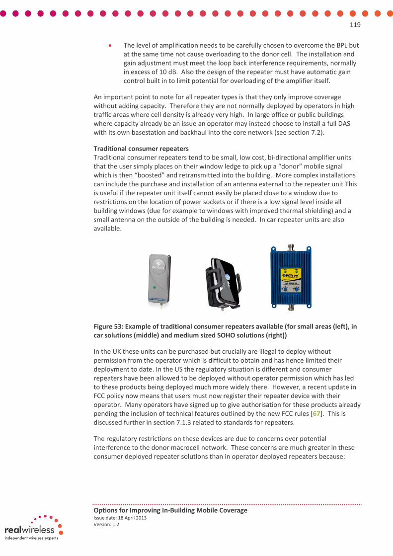
119
Options for Improving In-Building Mobile Coverage Issue date: 18 April 2013 Version: 1.2
The level of amplification needs to be carefully chosen to overcome the BPL but at the same time not cause overloading to the donor cell. The installation and gain adjustment must meet the loop back interference requirements, normally in excess of 10 dB. Also the design of the repeater must have automatic gain control built in to limit potential for overloading of the amplifier itself.
An important point to note for all repeater types is that they only improve coverage without adding capacity. Therefore they are not normally deployed by operators in high traffic areas where cell density is already very high. In large office or public buildings where capacity already be an issue an operator may instead choose to install a full DAS with its own basestation and backhaul into the core network (see section 7.2).
Traditional consumer repeaters Traditional consumer repeaters tend to be small, low cost, bi-directional amplifier units that the user simply places on their window ledge to pick up a “donor” mobile signal which is then “boosted” and retransmitted into the building. More complex installations can include the purchase and installation of an antenna external to the repeater unit This is useful if the repeater unit itself cannot easily be placed close to a window due to restrictions on the location of power sockets or if there is a low signal level inside all building windows (due for example to windows with improved thermal shielding) and a small antenna on the outside of the building is needed. In car repeater units are also available.
Figure 53: Example of traditional consumer repeaters available (for small areas (left), in car solutions (middle) and medium sized SOHO solutions (right))
In the UK these units can be purchased but crucially are illegal to deploy without permission from the operator which is difficult to obtain and has hence limited their deployment to date. In the US the regulatory situation is different and consumer repeaters have been allowed to be deployed without operator permission which has led to these products being deployed much more widely there. However, a recent update in FCC policy now means that users must now register their repeater device with their operator. Many operators have signed up to give authorisation for these products already pending the inclusion of technical features outlined by the new FCC rules [67]. This is discussed further in section 7.1.3 related to standards for repeaters.
The regulatory restrictions on these devices are due to concerns over potential interference to the donor macrocell network. These concerns are much greater in these consumer deployed repeater solutions than in operator deployed repeaters because:

120
Options for Improving In-Building Mobile Coverage Issue date: 18 April 2013 Version: 1.2
Traditional consumer repeater products tend to be broadband units capable of being configured to work across a number of operators. They tend not to have the same level of channel selectivity as an operator deployed repeater solution.
Unlike an operator repeater solution, in consumer deployed repeaters the operator has no direct control over where the unit is used, its settings and hence any ability to control interference to the donor macrocell network.
The same level of skilled installation and setup associated with operator deployed repeaters to minimise interference simply cannot be expected or achieved with these consumer deployed equivalents.
Generally the low cost and small form factor of these consumer deployed repeaters means that good isolation is difficult to achieve between the two opposite facing antennas in the unit which in turn limits the amplification that can be achieved without having feedback issues. This, combined with the placement of the unit on a window ledge rather than having an antenna external to the building, will limit the levels of service improvement that these units can achieve in practice.
Intelligent repeaters Intelligent repeaters are a recent update to traditional consumer repeater products and consist of two boxes (i.e separate donor and mobile units) with integral patch antennas which are linked by a 5GHz radio link (i.e. the same licence exempt band as used by the most recent Wi-Fi devices). The outdoor “donor” signal is picked up by the donor box, digitised and transmitted to the mobile unit via the 5GHz link and then retransmitted by the mobile unit. This allows the donor unit to be located near a window and the mobile unit to be positioned where the coverage improvement is required. While the mobile unit can be located at the target area there should not be any significant obstructions in the path of the 5GHz interlink signal. This normally implies that a LOS link is required for optimum performance.
These products aim to minimise interference to the macrocellular network by:
Using intelligent power control
Having good isolation between the donor and indoor antenna as these are in separate boxes
Repeating the signal from within the building rather than on the window which isolates the indoor signal from the outdoor macrocellular network better
Allowing the operator to remain in control of the unit by providing a simple management feature which allows operators to remotely signal to the intelligent repeater unit to switch off should the operator observe that the unit is causing interference.
Figure 54: Only commercial intelligent repeater solution that we are aware of (from Nextivity)

121
Options for Improving In-Building Mobile Coverage Issue date: 18 April 2013 Version: 1.2
This evolution of traditional consumer repeaters has notably been approved by some UK network operators2 who are deploying these solutions in specific cases of poor indoor service. Crucially in these cases these devices are legal to use and within the current Ofcom guidance on the use of repeaters.
Currently we are only aware of one intelligent repeater that is commercially available which is from Nextivity. At present this has a high retail price of around £450 which may be prohibitive for some consumers if it is not subsidised by the operator in some way.
Recently available LTE gateway products can be seen as extensions to intelligent repeaters. These are fixed consumer premise equipment units (CPEs) that provide a fixed broadband connection to a home from an outdoor LTE network. However, instead of providing a LTE signal indoors this broadband connection is distributed via Wi-Fi or a fixed Ethernet cable. However, this limits services available to data services due to the limitations of Wi-Fi for providing cellular like services as discussed in appendix D. LTE relays represent the next evolution of these products will include the ability to extend the coverage area of existing LTE cells. However, no LTE relay products are as yet available.
7.1.3 Standards
Interoperability Due to their relatively simple operation not many standards exist for repeaters. However, 3GPP have generated specified baseline RF transmission and reception requirements specifically for repeaters in TS 25.106 [68] in the case of UMTS and TS 36.106 [69] in the case of LTE. These specifications focus on defining maximum transmit power levels, spectrum masks and spurious emission limits which may cause unwanted interference. Conformance testing against these is specified in TS 25.143 [70] and TS 36.143 [71].
However, this lack of standardisation in repeaters does not make them especially difficult to build or preclude vendors particularly in the case of operator deployed repeaters.
In the case of consumer deployed repeaters, in the UK at least, while there have been no direct barriers to vendors producing consumer repeater products, and indeed a range are available to purchase online, the deployment of these has been limited by the regulatory rules put in place on the use of such products to protect operators from interference in their licenced spectrum. These currently require consumers to gain approval for their repeater product from their operator prior to deployment. This is generally difficult to obtain as UK operators remain to be convinced that traditional consumer repeater products will not cause interference to their networks.
In the US the opposite has been true and repeaters have been permitted to be deployed without specific permission from operators leading to their wide scale use there. However, recently the FCC position on repeaters has been revised notably to [72]:
More tightly specify the functionality and performance of commercial repeaters.
Require all users of repeaters, both legacy users and new users, to register their device with their operator and gain their approval for its operation.
2 From stakeholder discussions these have included sales of units in limited amounts to O2, Vodafone and
Orange (now EE).

122
Options for Improving In-Building Mobile Coverage Issue date: 18 April 2013 Version: 1.2
This move towards tighter specification of the technical functionality and performance of consumer repeaters means that this allows operators to confidentially approve deployment of particular product ranges. Indeed in the US all four nationwide carriers are reported to have consented to the use of consumer repeaters on their networks for products within the new regulations [67]. However, it is likely that operators will always have a preference for knowing and controlling where repeaters are deployed.
This tighter regulation may in the short term limit availability of consumer repeaters to perhaps even just the intelligent repeater solution currently available from Nextivity but there are no barriers seen on why other vendors could not upgrade existing product ranges to offer similar features to meet these tighter technical requirements.
Security We have not identified any major security concerns with repeater solutions. Generally repeaters can be seen as an additional amplifier in the operator’s macrocellular network with the same 3GPP security standards applying as would be the case in a traditional macrocellular network.
However, as repeaters are deployed on the customer’s premise rather than on an operator’s site there may be concerns over the physical security of these products and the risk of tampering by consumers. Repeaters do not directly recover any control or user plane traffic in the process of their operation and so the ability for a consumer to use a repeater to generate control traffic to gain access to an operator’s network will be very much limited, and likely be even less of a concern than in cellular small cells where some network functionality is handled by the small cell. The main concern from the physical tampering of devices is whether a user could reconfigure a device for higher transmit powers or to use different bands. While this is possible in theory our discussions with stakeholders have indicated that in practice safeguards are put in place such as encryption of the software running on the device and of the configuration parameters. Also it is likely that concerns in this area could be addressed via similar best practice principles to those suggested for cellular small cell and Wi-Fi in earlier appendices.
Authentication and handover We have not identified any major concerns regarding authentication and handover with repeater solutions as these simply work as an extension to the existing macrocell coverage area and so the same handover or authentication procedures as used in macrocellular networks will be applied transparently.
7.1.4 Industry ecosystem
As discussed in section 7.1.3, 3GPP standards exist to define the RF characteristics of repeaters and these are sufficient for a range of vendors of operator deployed repeaters to have already developed product ranges against. In the case of traditional consumer repeaters, there are a range of vendors for these products but gaining approval amongst operators is more of a challenge. This has not been helped by a lack of consensus amongst operators on what technical features these devices should have to minimise interference. The new FCC guidelines on repeaters go some way towards specifying a minimum specification for consumer repeaters which operators in the US, at least, have been willing to give their support towards. Adoption of a similar minimum specification for consumer repeaters in the UK, with appropriate operator support, would give vendors of consumer repeaters a clear baseline performance level to meet. This in turn would

123
Options for Improving In-Building Mobile Coverage Issue date: 18 April 2013 Version: 1.2
likely broaden the range of consumer repeater devices that could be deployed, rather than just sold, in the UK.
Currently the range of consumer repeater products that can be deployed in the UK is limited to the Nextivity product in the restricted locations where operators have supported the supply of this product. However, if an appropriate minimum standard for consumer repeaters was adopted in the UK there is no obvious reason why this range of vendors supported could not be extended.
Traditionally operators have not been involved in the installation and management of consumer repeaters but this is changing with the introduction and approval of intelligent repeaters by operators. This is helped further with the rules in place now in both the UK and US to ensure that users register their repeater with their operator and gain approval to use it prior to installation. This increasing involvement of operators in the deployment of consumer repeaters may mean that these products can start to be offered more widely as part of operator mobile packages. If this was the case operators might choose to subsidise the cost of repeater solutions which are currently in the region of £450 for intelligent repeater products and likely too high for most consumers. We would envisage the costs would reduce considerably if the volumes increased significantly.
Currently consumer choice is limited to a single operator if they choose to use a repeater solution. Technically it is possible to have multi operator repeaters but there are some challenges due to the potential interference to existing macrocells across multiple operators which would need to be co-ordinated and agreed. This issue is complicated by the fact that no two operators will have the same set of macrocell network sites and so interference across operators will vary with location. The cost of repeater solutions is also high (£450 for the Nextivity solution) which makes changing operator difficult once a consumer has made the investment in a repeater product from their existing operator. This high price tag may improve the case for Ofcom input to encourage multi operator support in these products.
7.1.5 Current availability and future evolution
Current and future availability As discussed earlier, products for operator deployed repeaters are widely available and deployed in many different scenarios today. The deployment of these will likely continue for the foreseeable future in specialised coverage challenged scenarios like tunnels or medium sized, low capacity buildings where a good outdoor signal exists but a backhaul connection may be challenging/expensive to obtain.
In the case of consumer repeaters, again as highlighted earlier, multiple products are available to purchase online but their deployment is limited by current UK policy regarding repeaters aimed at protecting operators from harmful interference and a lack of support for these products by operators. The evolution of the UK regulatory situation with regard to consumer repeaters and operator attitudes towards new more “intelligent” product ranges will obviously have a crucial role to play in the future availability and deployment of these products in the UK.
As repeaters do not require an existing broadband connection they have an advantage over cellular small cell solutions, in particular femtocells, and are therefore a good fit for a particular subset of indoor users requiring an in-building solution. Therefore it is likely

124
Options for Improving In-Building Mobile Coverage Issue date: 18 April 2013 Version: 1.2
that repeaters will continue to have a role to play for particular indoor user groups and be deployed alongside femtocells if the regulatory and operator approval issues can be resolved. LTE-A relays may also be viewed as an evolution of intelligent repeaters and so the uptake of LTE-A and the possible incorporation of these relays into cellular networks may aid the uptake of repeater products taking on this form also. However, there are currently no LTE-A relay products commercially available and so it likely to be some time before these are seen fully incorporated into cellular networks.
Finally, in terms of the scalability of repeaters, if the take up of consumer repeaters does become high the cumulative negative impact of interference on the macrocell network may limit the future roll out numbers of these products. While this may not be an issue in isolated rural areas the cumulative interference effect certainly becomes a potential concern in urban areas.
Current and future spectrum requirements In the case of operator deployed and traditional consumer grade repeaters, these products will have the same spectrum requirements as existing macrocell networks as they are simply an extension to the coverage area of these networks with no change in carrier frequency needed.
The exception to this is intelligent repeaters which could make heavy usage of licence exempt spectrum. For example, the Nextivity solution currently requires continuous use of two blocks of spectrum each of 40MHz bandwidth at 5GHz to operate. This solution does include dynamic frequency selection to allow it to co-exist with other users of this band, including radar and 802.11ac. However, this does raise concerns on whether the solution will reliably work in particular areas where this frequency band is already being used. Access to more low power licence exempt spectrum may therefore be needed to support the uptake of these intelligent repeater solutions. This could include spectrum only available on a regional basis but probably at high frequencies where a large amount of bandwidth is available.
7.1.6 Environmental impact
In terms of power consumption the environmental impact of consumer repeater solutions should generally be at a similar level to femtocells or Wi-Fi access points. The exception to this is two box intelligent repeater solutions where there are two units rather than one to power and so total power consumption will likely be higher. In the case of operator deployed repeaters these will be at higher power levels than consumer deployed repeaters but perhaps similar in power consumption to picocells products.
From a health and safety perspective, all repeater products need to achieve ICNIRP compliance as with all RF products and so technically there should be no issues in this area. However, public perception may be an issue particularly for larger operator deployed installations where antennas are visible. In the case of repeaters coupled with a DAS “touch safety” rules will apply to the indoor antennas as would be the case with any DAS deployment.
7.1.7 Operator deployment views
Repeaters offer the key benefit to operators of providing an opportunity to address poor service levels without requiring backhaul connectivity in the target area. However, they

125
Options for Improving In-Building Mobile Coverage Issue date: 18 April 2013 Version: 1.2
can only be used for enhancing coverage over a relatively small area due to their limited transmit power levels as a result of a usually lower donor signal. Most of the repeaters deployed by operators today are therefore in tunnels, small offices and shops.
In terms of deployment issues, the donor antenna is normally mounted outside the building ideally on the roof top and this may delay its deployment because of the need to obtain permission from the building owner. Planning permission is generally not required if the antenna can be mounted quite close to the roof and in the case of residential premises (executive homes for example) the antenna may be located inside the loft.
As already highlighted the deployment of repeaters requires careful engineering, and hence is led by the operator, for the following reasons:-
The deployment needs a reasonable level of donor signal otherwise it will be ineffective
Repeaters can be seen as an RF noise source and so the repeater gain has to be carefully adjusted so that it is not causing noise overload into the donor base station. For this reason repeaters should not be used close to a base station.
The donor antenna needs to be carefully oriented to avoid picking up unwanted donor signals which may be repeated and amplified causing interference on the uplink. Therefore a highly directional antenna is used.
For these reasons network operators are not in favour of traditional consumer repeaters which may not improve customer satisfaction and may indeed cause harm in the form of interference to the macrocellular network.
Intelligent repeater solutions offer a more effective solution than traditional consumer repeaters because the mobile unit can be positioned where improved coverage is required while the donor unit can be placed near a window to pick up the outdoor signal to be enhanced. Some UK operators have already approved the use of these solutions in some deployment cases which suggests that there may be a changing attitude towards consumer repeaters in the UK by operators.
Despite these approvals by operators, consumer repeaters should still ideally be acquired via an operator so that operators can assess the usefulness of the solution based on their coverage database and also make sure that it is going to be deployed at the stated address. In some cases operators have gone as far as investigating mechanisms for remotely deactivating repeaters. For example, T-Mobile has a patent application in this area.
In terms of the impact of repeaters on the macrocellular network, repeaters do not add capacity to the network but simply extend coverage. While this has the positive impact on the macrocellular network of providing service where no or poor levels previously existed, this does not necessarily improve the average quality of service received by users across the extended macrocell area. This is because hard to reach indoor users are now added with no offload benefit (whereas cellular small cells, for example, would extend coverage and bring this offload benefit).
In terms of any uplink vs. downlink imbalance issues, as the donor signal is boosted so too will be any noise in the system. This may result in an increase in the noise floor of the mobile device and hence cause uplink limitations. This may in turn hinder the scalability of

126
Options for Improving In-Building Mobile Coverage Issue date: 18 April 2013 Version: 1.2
repeater solutions although is not normally an issue if the deployment is carefully controlled by the operator.
Currently operators are likely to consider deploying intelligent repeaters before cellular small cells as there deployment does not require any additional network infrastructure such as security and HNB gateways and hence integration into the network is easier. In the longer term it is likely that cellular small cells will be deployed alongside consumer repeaters rather than being direct competitors to them as they address consumers with different existing indoor coverage problems. For example, cellular small cells address users who have a broadband connection but no existing indoor or outdoor signal whereas repeaters are aimed at those who have outdoor coverage but no indoor coverage and possibly no/a limited broadband connection.
7.1.8 Assessment against Ofcom’s criteria
Table 26 provides a summary of how repeaters score against the original project requirements set out by Ofcom. In the case of each requirement we give a red, amber or green score depending on whether there are any major blocking issues, minor issues or no issues against each requirement respectively.
Study requirement Score Comments
Current status, take up and availability
Repeater products widely available but deployment limited by regulatory position on repeaters in the UK. The arrival of intelligent repeaters may change this. US approach to repeaters is worth monitoring and perhaps reviewing for the UK as these products do fit well as the only solution for niche indoor users with poor indoor cellular service, a good outdoor cellular signal level but no broadband connection.
Openness No obvious barriers to vendors buildings repeater products.
Consumer choice across operators limited by high cost (particularly in intelligent repeaters) with single operator products only available currently.
Authentication and handover
Authentication and handover occur as in macro network so no issues found here.
Security Uses 3GPP existing security model for macrocell network user and control plane traffic. Physical security of consumer repeaters may be an issue and industry best practices should be formed and followed in this area.
Will not be able to support 999 calls in a power cut.
Impact on the macro No positive offload impact on the macro network as repeaters provide an extension of coverage rather than capacity.
Negative impacts such as interference and increased loading of the macrocell by hard to reach indoor users may occur.
Uplink or downlink constraint
Uplink may be limited due to noise being amplified in repeater retransmissions.
Current and future spectrum
Same spectrum as used by macrocells.
Intelligent repeaters make heavy usage of unlicenced spectrum due to continuous transmissions and wide bandwidths of up to 40MHz needed.
Environmental impact Power consumption similar to Wi-Fi access points or femtocells although intelligent repeater requires two units.

127
Options for Improving In-Building Mobile Coverage Issue date: 18 April 2013 Version: 1.2
Study requirement Score Comments
Future evolution Level of future deployment is uncertain and will largely be driven by regulatory position on repeaters and operator support of such devices. LTE-A relays may be viewed as a future evolution of repeaters but no products have been seen in this area yet.
Scalability Scalability of repeaters limited by the cumulative interference into the macrocell network particularly in urban areas.
Upgradeability Current consumer solutions are ASIC based and so likely not easily upgradeable without purchasing a new updated product at a high cost, particularly in the case of intelligent repeaters. Intelligent repeaters are also limited to UMTS currently.
Table 26: Summary of repeaters against the study requirements
7.2 Distributed Antenna Systems (DASs)
A distributed antenna system (DAS) is a system of indoor antennas installed throughout the building and connected together using coaxial or fibre cabling and routed back to a central basestation in the building. This basestation is in turn backhauled into the operator’s core network. This basestation and the DAS then appears as a distinct cell site on the operator’s network. Depending on the capacity requirements of the network smaller DASs may be fed by a picocell or repeater rather than a full macrocellular basestation.
Figure 55: Overview of a typical DAS installation
DAS can offer the advantage of a centralised base station installation which segregates the maintenance of the operator’s equipment from that of the DAS. This may be important where security is a main concern such as airports, for example.
7.2.1 Consumer proposition
Distributed Antenna Systems are normally used for medium to large enterprises for which the benefits of their use can be easily justified. If the end user is not the building owner they will see the benefits of DAS as an improvement to their existing cellular service.

128
Options for Improving In-Building Mobile Coverage Issue date: 18 April 2013 Version: 1.2
In the case of the business or building owner they may have to cover part or all of the cost of the DAS installation but for major corporate customers the operator is generally willing to pay all the costs incurred. However, there will inevitably be a lot of disruption with a DAS installation if appropriate cabling and antennas have not been built into the building from when it is first built and this is rarely the case.
Technically DAS systems can support multiple operators but this is cheaper to achieve in passive than active systems. In public venues multi operator DASs tend to be required to minimise the requirement to deploy multiple systems. In large corporate DAS systems, particularly when installed by the operator, this will be limited to a single operator for commercial reasons. From our operator discussions, there have even been cases of DAS systems being taken out and completely new systems being installed when corporations have changed operator – this large investment by operators/corporations can sometimes make changing operators less attractive on commercial grounds. In Australia building owners have gone as far as approaching the government and getting legislation passed to require operators to keep each other informed of DAS in-building deployments to encourage collaborative DAS deployments in an effort to try to avoid these situations.
Once installed the indoor service improvements seen by consumers from a DAS will include:
Better availability and quality of cellular voice, SMS and data services in the building
Better cellular data rates
Improved mobile phone battery life
Depending on the deployment the DAS may support all operators
Table 27 summarises how repeater solutions best fit across the user groups and buildings considered in this study. Note that cost is a major issue for most of them as is multi-operator support. The issue of cost in particular prohibits the use of DAS for many small to medium-size buildings, and even for large enterprises, it conditions its rollout; i.e. this is done in stages or phases, not all at once.
Home user Small office / SME Large multi storey office
Public buildings / areas
DAS is prohitively expensive for smaller buildings.
As for home users DAS may be justified in very large high capacity offices but may see this market eroded by picocells increasingly.
DAS ideally suited for very high density venues where multi operator support is needed.
Table 27: Fit of DAS across building types
7.2.2 Concept in more detail
A Distributed Antenna System (DAS) is a means for distributing radio signals over a large and complex coverage footprint, as shown in Figure 56. The number of antennas varies from several to hundreds depending on the size of the coverage area. In essence, it is a system of indoor antennas throughout the building connected together using coaxial or fibre cabling and routed back to a central base station in the building which is in turn

129
Options for Improving In-Building Mobile Coverage Issue date: 18 April 2013 Version: 1.2
backhauled into the operator’s core network. This appears as extra separate cell site on the operator´s network.
Figure 56: The DAS concept
The DAS infrastructure can be owned by an operator, a building owner or a neutral enterprise who offers the system to the network operators for a fee.
Types of DAS
In terms of types of DAS, there are passive, active or hybrid DAS. These are explained in more detail below.
Passive DAS. Passive DAS is made up of coaxial cables, splitters and couplers. It is normally used for small to large buildings with a relatively simple layout. It is the preferred DAS option because of its wide band nature and also because power handling is not normally an issue as long as the antenna radiated power complies with ICNIRP guidelines. On the other hand, due to the large noise figure that is added by passive elements, its use is often restricted to smaller buildings especially for noise-limited systems in the uplink, such as 3G. An example of a passive deployment is shown in Figure 57.
Figure 57: Overview of a typical passiveDAS installation

130
Options for Improving In-Building Mobile Coverage Issue date: 18 April 2013 Version: 1.2
Active DAS. Where a building has a complex layout and the space available for the installation of coaxial cables is limited or difficult to install, active DAS is used.
Active DAS is normally made up of a master unit which interfaces with the base station and distributes the radio signal to remote amplifiers installed near the target coverage areas. The connection between the master unit and the remote units can be in the form of CAT5/6 cables, multi-mode or single mode optical fibres. Thus, the master unit has the function of converting the radio signal from the base station into a lower frequency signal or optical signal depending on the medium used. The remote amplifier converts the signal back to the radio signal for radiation. Therefore an active DAS requires careful system dimensioning to ensure that the power handling is within the capabilities of the active elements. The coverage capability of each antenna can be engineered for the intended service requirements.
One of the characteristics of active DAS is that the amplifiers balance out any transmission losses which may occur in the link and also have a much better noise performance than passive DAS. They are also very flexible which means that zoning and different antenna configurations are possible with the simple reinstallation of the remote antenna units. On the other hand, they are much more expensive and complex to deploy and install than passive components.
Hybrid DAS. Hybrid DAS is a mixture of passive and active DAS making the best use of the base station output power. This configuration is normally used for buildings with either existing passive installations or for areas where it is difficult to have active DAS; e.g. due to power requirements. These systems, like all DAS installations, require expert detailed design, planning and installation.
Installation
The installation of a DAS system is generally challenging and requires a skilled team to be designed and installed successfully. Design and installation constraints include:
Cable routing to stay within maximum bend radius
Management of intermodulation between carriers in multi-operator systems
Management of handover and interference with neighbouring macrocells
Restrictions on antenna location due to aesthetic or physical access reason
Restrictions on cable routes due to access restrictions
Installation is extremely costly and therefore this type of solution tends to be used in high-capacity large buildings only; e.g. airports, shopping centres, large enterprises, stadiums. Figure 58 shows an example of a typical DAS installation.

131
Options for Improving In-Building Mobile Coverage Issue date: 18 April 2013 Version: 1.2
Figure 58: Behind the scenes of a typical DAS installation
7.2.3 Standards
Since DAS is not a direct product there are no public recommendations from a recognised body such as 3GPP, ETSI or IEC for DAS installations. Some industry developed best practice requirements have been specified for DAS installations but these are more related to the type of DAS deployment (multi-operator, etc.) or issues related to the elements which are installed in the DAS (health and safety, etc.). These are briefly explained below. Where a DAS supports multiple operators it must conform to the requirements defined in the Joint Operator Technical Specification (JOTS) [73] which is a specification agreed by all the main UK network operators. Although mobile service in the UK is competitive in nature, the technical teams across operators enjoy a good level of co-operation among themselves where there is a common interest prevailing. The JOTS specifies the requirements of the DAS installation including:
The base station interface
A 95% coverage level or link loss for specific areas within a building where different service types may be required
Intermodulation requirements
Co-existence with other installations such as Wi-Fi and PMR (Private Mobile Radio)
Achieving "Touch safe" for ICNIRP compliance
Handover between sectors and/or cells within the building and with external macrocells
Coverage overspill external to the building
Coverage tests
The concession process for the ward of a joint DAS across operators
Documentation of the design and installation
The original JOTS document was developed for GSM deployments. However, it is a live document which has been updated to include UMTS and LTE. It is an open specification jointly owned by the UK main network operators with EE taking the lead as the editor. Note that there is no requirement for JOTS conformance on individual operator DAS installations and in particular in those for their business customers. This can lead to

132
Options for Improving In-Building Mobile Coverage Issue date: 18 April 2013 Version: 1.2
operators installing a single operator DAS for commercial advantage and in extreme cases insisting that this is removed and reinstalled if corporate clients change operators. In Australia building owners have gone as far as approaching the government and getting legislation passed to require operators to keep each other informed of DAS in-building deployments to encourage collaborative DAS deployments and to try and avoid these situations. There are also standard joint operating agreements that have been developed by DAS industry groups for the technical and commercial details of these joint deployments which are similar in some ways to the UK JOTS. Australian legislation does not directly regulate that operators must collaborate on DAS deployments and indeed they do not when it is not technically or financially feasible to do so. It does require them to keep each other informed of DAS plans and this step appears to have been enough to have encouraged a self-regulating co-operative approach to DAS by operators in Australia. There may be lessons that the UK could learn from this. It is worth noting that a more likely scenario if a corporate customer has an existing DAS installation and changes operator is that the old operator may be prepared to sell the existing system to the new operator partly to recover the cost of installation but more importantly to avoid the costs of decommissioning the system – this whole area is complex and may ultimately depend on what the terms of the agreement are between the incumbent operator and the corporate customer.
Openness
DAS interfaces are well defined and understood for multi-operator systems which have been successfully deployed in many public buildings. However, multi-operator support must be carefully designed in due to issues such as:
Management of intermodulation between carriers in the cabling
Management of handover and interference with neighbouring macrocells
Many building designs in practice differing from the multi-operator guideline for DAS deployments in the JOTS
Technically, DAS is an extension of the normal cellular macrocell network and so follows the same set of 3GPP standards. This makes the use of standard interfaces a reality and so any vendor could in principle build DAS products.
Authentication, handover and security
Since a DAS forms part of normal cellular network it follows the same authentication and handover procedures as in the rest of the macrocellular network. Handover can be complicated in some areas due to issues with macrocells at the building edge. An example of this is the handover at building entrances and boundaries which needs to be carefully designed to avoid interference to neighbouring macrocells.
In terms of security, 3GPP security standards are implemented as part of the larger macrocell network, so security is not a concern.

133
Options for Improving In-Building Mobile Coverage Issue date: 18 April 2013 Version: 1.2
7.2.4 Industry ecosystem
Network operators, building owners and enterprises normally contract out the design and installation of DASs. There are several contractors in the UK capable of performing these tasks, mostly in the form of SMEs. There are many suppliers who are able to supply the passive components for DASs such as coaxial cables, couplers, splitters, combiner and antennas. These are both UK and internationally based. On the other hand, the number of active DAS suppliers is rather limited as the number of deployments is relatively small relative to passive systems. Companies providing the systems in the UK today include Axell Wireless, Commscope, Power Wave and Zinwave.
ABI research’s rank of top DAS vendors lists Corning MobileAccess, Commscope and TE Connectivity as the top three DAS vendors based on a combination of innovation and implementation. However on innovation alone upcoming companies Corning MobileAccess, Zinwave and Alvarion are the top three and likely to take more of a market share with single cable MIMO support, CAT5 based DAS solutions for small enterprises and improvements to DAS costs, flexibility and scalability [74].
Generally, there are a limited number of suppliers of DAS networks in the UK because specialised RF design skills are needed. In terms of the market for DAS solutions this also tends to be limited to a low number of large high capacity buildings (although there is a continuous supply of these buildings being built) that DAS is well suited for. See Table 28 for an indicative chart of the potential business market for DAS in the UK based on the number of large businesses reported. This means that the number of suppliers to address this market also tends to be limited and highly specialised.
Employees Businesses Percentage of total businesses
Percentage of total private employment
1-9 (Micro) 1,022,695 82.3% 19.2%
10-49 (Small) 177.950 14.3% 17.3%
50-249 (Medium) 29,750 2.4% 14.5%
250+ (Large) 6,455 0.5% 48.6% *Excludes sole proprietorships and partnerships comprising only the self-employed owner-manager(s) and
companies comprising only an employee director.
Table 28: Statistics on the size of UK business giving an indication of the potential size of the DAS business market if only really applicable to large businesses [75]
In terms of revenue, DAS is a significant market with active DAS equipment revenues predicted to reach $1 billion globally by 2013 (50% of the total in-building equipment market made up of repeaters, passive and active DAS, cabling and antennas). The overall revenue of in-building equipment, including labour, is likely to reach $3.6 billion. Active DAS revenue globally has a CAGR of 15% and 20% in the US where strongest. Passive DAS CAGR in US in contrast is slowing and only at 6%. An increasing trend to note is that picocells tend to overlap with DAS in small to medium sized buildings and are forecast by some to erode the share of DAS installations in these areas[76].

134
Options for Improving In-Building Mobile Coverage Issue date: 18 April 2013 Version: 1.2
7.2.5 Current availability and future evolution
Current and future availability
DAS is nowadays a globally-established practice for medium to large in-building mobile service deployments. High design expertise and a large project budget are both required so it tends to only be deployed at modest levels in small to medium-sized enterprises.
Although there is the question of whether picocells will erode the DAS market it is likely that DAS will still be required and preferred in high-capacity deployments which picocells may not be well suited for. From our stakeholder discussions operators tend to prefer “tried and tested” in-building solutions like DAS over emerging solutions like picocells which require additional network infrastructure to be fully integrated into the operator’s network. This is supported by market reports which show 73% of operators using small cells (but mostly femtocells) while 80% of operators still use DAS systems [77].
Spectrum requirements
Current and future spectrum requirements for DAS are envisaged to be the same as for macrocell elements of cellular systems.
Future evolution
It is difficult for DAS to include MIMO due to the multi-antenna nature of the technology. Also it is difficult to retrofit upgrades to DAS solutions due to the bespoke RF planning that goes into the original system design. Thus, in terms of upgrades to keep track of technology and the latest air interfaces, DAS will have various restrictions in terms of its support for multiple bands and multi antennas compared with, for example, cellular small cells. However, emerging enhancements to DAS include digitising and multiplexing multiple signal streams through the fibre cables connecting the antenna units to support multiple technology, band or MIMO deployments.
Upcoming companies in DAS systems, such as Corning MobileAccess, Zinwave and Alvarion are likely to take an increasing market share with single cable MIMO support (via multimode fibre), CAT5 based DAS solutions for small enterprises and improvements to DAS costs, flexibility and scalability. For example, Zinwave deployments supporting LTE across multiple bands (700MHz, 850MHz, 1900MHz and 2100MHz) and multiple air interfaces (2G, 3G, cdma, public safety and WiMAX) have been used in the US already [78]. Also TE Connectivity have successfully trialled MIMO DAS systems and showed the benefits of these based on converting DAS signals to IF which allows multiple MIMO signals to be sent over a single fibre reducing the transmission cost [79].
Distributed Base Stations
Another in-building solution that can be viewed as an evolution of DAS is the use of distributed basestation solutions. These tend to have a central basestation feeding multiple remote radio head units connected back to the basestation with high speed, low latency fibre connections. The central basestation intelligently co-ordinates coverage and capacity across the network of antennas to dynamically provide the level of service enhancement where it is needed as users move around the venue/coverage area. Other architectures on a similar theme include a central basestation controlling multiple picocells access points and intelligently controlling interference amongst these to provide

135
Options for Improving In-Building Mobile Coverage Issue date: 18 April 2013 Version: 1.2
impressive capacity gains which should cover even the most densely populated venues/ areas. This is the concept of distributed base stations is shown in Figure 59.
Figure 59: Distributed base stations
The idea of BS hoteling or distributed base stations has been around for a long time. It involves having a centralised BS, in a telephone exchange for example, feeding into a network of antennas located remotely. The key disadvantage of this approach is that RF signals need to be transmitted over long cables which may be expensive if done over optical networks, as this requires dark fibre. On the other hand, the concept generally fits well with DAS deployments and includes advances such as CoMP to minimise interference and achieve impressively high capacity levels.
In terms of the evolution of distributed base stations, remote radio head interfaces have evolved over time within CPRI (Common Public Radio Interface) and OBSAI (Open Base Station Architecture Initiative). CPRI and OBSAI standards provide basic interoperability but CoMP techniques applied are largely proprietary. More recently, these systems have been called “Cloud RAN” systems but this is just a rather sophisticated name for an old idea of placing more intelligence between antennas in a DAS via techniques such as CoMP in LTE-A.
Example distributed basestation products include:
Alcatel-Lucent “Light Radio” (http://www.alcatel-lucent.com/solutions/lightradio)
Nokia-Siemens’ “Liquid Radio” (http://www.nokiasiemensnetworks.com/portfolio/liquidnet/liquidradio?utm_source=Google&utm_medium=cpc&utm_term=nsn%20liquid%20radio&utm_content=AG_Liquid_Net&utm_campaign=NSN_Liquid_Net&_oskwdid=12669764&_engineadid=32866320337)
Nokia-Siemens “Flexi-Zone” solution (http://gigaom.com/2012/02/21/like-cloud-operators-nsn-is-now-all-about-fabrics/)

136
Options for Improving In-Building Mobile Coverage Issue date: 18 April 2013 Version: 1.2
Figure 60: Emerging distributed basestation systems include Alcatel Lucent’s Lightradio solution and NSN Liquid radio solution
Distributed BS solutions will not be found in the home but are a good fit to enterprise deployments and top end DAS solutions. There is a question over how multi-operator support would work in Cloud RAN systems and this issue is yet to be fully resolved. Fundamentally distributed BSs are the reverse to the argument for femtocells of putting low cost intelligence at the network edge rather than at the core.
7.2.6 Environmental impact
DAS systems tend to be very wasteful of power. Typically, the central base station is run at full power and then reduced via attenuators to an appropriate level for the building (especially for passive DAS).
In terms of aesthetics, building owners need to be comfortable with multiple antennas visible around their site for DAS installations. Antennas tend to be designed to look like smoke detectors etc., as shown in Figure 61, to disguise them to a certain extent. Designers should also be aware that for specific areas within a building antennas cannot be mounted or deployed; e.g. VIP lounge of an airport main terminal building.
ICNIRP compliance is not trivial and specific SAR testing of antennas is usually needed for DAS installations. Sometimes shrouds are required over antennas to make them “touch safe” and RF safety needs to be built in.
Figure 61: Example DAS antenna designed to look like a smoke detector
7.2.7 Operator deployment views
Simple passive DASs are commonly deployed by network operators today to achieve coverage in target areas which is coverage challenged. The decision to deploy DAS over picocells is a balance between the DAS cost against the cost of individual base station or picocell installations. Where a large active DAS is to be deployed it is normally built for multi-operators with the cost shared across participating operators in an open book business approach. Late

137
Options for Improving In-Building Mobile Coverage Issue date: 18 April 2013 Version: 1.2
participants to these schemes may pay a penalty such as interest incurred to date. In these deployments the lead operator devises a fair way to distribute the cost contributions across all participating operators. Importantly the system should ideally be designed to be fair from service point of view also i.e. the available power is shared across the main frequencies that the participating operators use rather than necessarily all the frequencies that could be used. Full multi-operator participation in a DAS installation may cause a delay to the project and so some operators may decide to take a business risk and build systems meeting the JOTS requirements without commitment from other operators at the outset. Once the system is built and operational the other operators are then invited to join. This is particularly true for important public venues where all operators are keen to have a presence. Despite this approach being a business risk, it offers the benefit to the lead operator of an early presence of coverage until the other operators have their system integrated (which may be several months after the system is operational for the lead operator). The benefit to the building/venue owner in this case is that a DAS is deployed earlier than if the lead operator had to wait until all operators agreed terms to participate (indeed there are lots of cases where one or more operators may never participate in a shared system).
Building mobile services into large buildings from the start Despite the fact that mobile service is part of everyday life, it seems that mobile coverage is not a consideration for the building developer/owner until after the building has been designed and built. At present, the mobile systems tend only to be considered at the earliest towards the end of a new building’s construction and may well create conflicts with the building architect who will be reluctant to have the building aesthetics spoilt by antenna for example. These practical conflicts can cause delays to DAS projects and impose conditions that lead to inefficient coverage due to unsatisfactory antenna positions. Invariably the cost of deploying containment, cabling, antenna and equipment in a building as part of a retrofit will be far higher than if some or all of the main components had been installed as part of the main building project. Another deployment barrier is that some public site owners consider mobile coverage as a revenue stream and require high rent levels from operators for DAS installations despite the fact that mobile coverage would be beneficial to themselves and their users. In extreme cases, this has result in some DAS projects simply not proceeding. Generally the deployment of DAS in public buildings, in particular, would be aided if developers were encouraged to involve the network operators or a DAS designer/installer as part of the building construction, similar to the need of providing facilities (pipe work, electrical and fixed line telecoms cables) for the utilities.
Buildings targeted for DAS by operators In the past it was very difficult for network operators to get permission from a hotel owner or a public venue owner, such as shopping centre, to install a DAS for mobile service due to the worry about eroding revenues from the hotel telephone service or payphones. This has now changed with the hotel owners now approaching operators for the improvement of mobile service levels in their buildings. Some even go as far as to fund/part fund the DAS installation themselves and although there are relatively few examples of this to date it is anticipated that it will become more common over time.
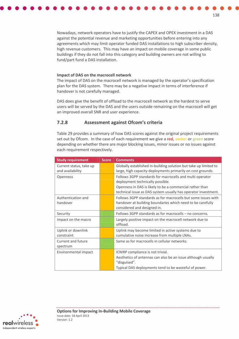
138
Options for Improving In-Building Mobile Coverage Issue date: 18 April 2013 Version: 1.2
Nowadays, network operators have to justify the CAPEX and OPEX investment in a DAS against the potential revenue and marketing opportunities before entering into any agreements which may limit operator funded DAS installations to high subscriber density, high revenue customers. This may have an impact on mobile coverage in some public buildings if they do not fall into this category and building owners are not willing to fund/part fund a DAS installation.
Impact of DAS on the macrocell network The impact of DAS on the macrocell network is managed by the operator’s specification plan for the DAS system. There may be a negative impact in terms of interference if handover is not carefully managed.
DAS does give the benefit of offload to the macrocell network as the hardest to serve users will be served by the DAS and the users outside remaining on the macrocell will get an improved overall SNR and user experience.
7.2.8 Assessment against Ofcom’s criteria
Table 29 provides a summary of how DAS scores against the original project requirements set out by Ofcom. In the case of each requirement we give a red, amber or green score depending on whether there are major blocking issues, minor issues or no issues against each requirement respectively.
Study requirement Score Comments
Current status, take up and availability
Globally established in-building solution but take up limited to large, high capacity deployments primarily on cost grounds.
Openness Follows 3GPP standards for macrocells and multi operator deployment technically possible.
Openness in DAS is likely to be a commercial rather than technical issue as DAS system usually has operator investment.
Authentication and handover
Follows 3GPP standards as for macrocells but some issues with handover at building boundaries which need to be carefully considered and designed in.
Security Follows 3GPP standards as for macrocells – no concerns.
Impact on the macro Largely positive impact on the macrocell network due to offload.
Uplink or downlink constraint
Uplink may become limited in active systems due to cumulative noise increase from multiple LNAs.
Current and future spectrum
Same as for macrocells in cellular networks.
Environmental impact ICNIRP compliance is not trivial.
Aesthetics of antennas can also be an issue although usually “disguised”.
Typical DAS deployments tend to be wasteful of power.

139
Options for Improving In-Building Mobile Coverage Issue date: 18 April 2013 Version: 1.2
Study requirement Score Comments
Future evolution DAS has evolved from passive to active systems and from using coax to fibre. No obvious next steps currently but will evolve as technology evolves.
Question over how well DAS will lend itself to future cellular air interfaces including MIMO and carrier aggregation. Technologies to multiplex multiple DAS streams are emerging to address this but stakeholder discussions show MIMO deployments of DAS are very limited currently and beyond 2x2 not considered practical by many.
Scalability Costly and time consuming to deploy so does not scale well.
Upgradeability Challenging to add more carriers or new air interfaces retrospectively due to up front RF design needed. Also issues with supporting features like MIMO (but views on this varied amongst stakeholders). Some upgrades can involve new cable runs and be very costly with some stakeholders indicating that in the case of 10 year old DAS systems it is technically a better solution to replace the DAS completely but a significantly higher cost than just upgrading and maintaining the existing system.
Table 29: Summary of DAS upgrades against the study requirements

140
Options for Improving In-Building Mobile Coverage Issue date: 18 April 2013 Version: 1.2
8. Appendix G – Detail of stakeholder engagement undertaken for this study and summary of key points raised
This appendix details the stakeholder engagement process carried out to support this study for Ofcom into options for in-building services. It provides an overview of the stakeholders contacted and the key points raised for each technology option and about the in-building landscape more generically.
8.1 Overview of the stakeholder engagement process
The information gathered for this study drew upon the practical, technical and commercial knowledge of the mobile industry. The objective of the stakeholder engagement was to target a broad cross section of companies from the mobile ecosystem that represented each of the mobile technologies considered as part of the study which included:
Mobile operators
Wi-Fi vendors
Enterprise small cell vendors
Femtocell vendors
DAS vendors
In building software vendors
Intelligent repeater vendors
We would like to thank and acknowledge the following companies and specifically the people from those companies that took time out to discuss the issues of improving in building coverage with us which included:
Airspan
Cisco
Commscope
H3G
iBWave
ip.Access
Nextivity
NSN
Optus
Ruckus Wireless
SpiderCloud
Stoke
Telefonica O2
The stakeholder engagement provided key data points and addressed specific issues to provide a representative and current view of how the attributes of each technology contributes to improving in building mobile coverage. In addition, the discussion provided useful insight to the latest developments in technology and future roadmaps of products and standards.

141
Options for Improving In-Building Mobile Coverage Issue date: 18 April 2013 Version: 1.2
The following overview focuses on the relevant points for each technology addressing issues such as:
Openness
Security
Handover challenges
Environment impact
Access to 999/112
Ecosystem evolution
In the sub sections below we provide a summary of the responses from across the stakeholders which we have divided into the respective technology options that can support in building coverage.
8.2 Summary of Wi-Fi stakeholders
The following views have been summarised from the discussions held with Wi-Fi vendors. Note these views are not attributed to any specific company and represent a broad view from across the stakeholders we interviewed:
General status
All Wi-Fi vendors acknowledged the need to satisfy in building coverage but the focus more recently has been addressing capacity most notably in the enterprise and hot spot environments rather than residential premises
Capacity density is the driving issue behind Wi-Fi deployments which will continue over the next few years
There is a breakpoint to the size of buildings that have a dedicated in building solution
Coverage and capacity issues occur in buildings with high concentration of users such as in public buildings, transit from the public such as hospitals, universities, shopping malls etc.
Operators are locked in to the traditional indoor deployments with little differentiation on offer, more Multi Operator Core Network (MOCN) will start to emerge
Wi-Fi vendors are focusing on addressing the high density usage indoors with on-going work to facilitate the integration of multi-RAT to offer a seamless environment for the user to access all mobile services
Wi-Fi players see IP Multimedia Subsystem (IMS) as the solution to decouple legacy services such as voice and data services
Unlicensed Mobile Access (UMA) seems to be a defunct solution for providing particular services over Wi-Fi
General issues relating to Wi-Fi and improving in building coverage
The Wi-Fi stakeholders provided general information relating to Wi-Fi and improving in building coverage across the various technology platforms and evolutions. Below is a summary of the observations raised by Wi-Fi stakeholders against the specific issues.
Wi-Fi landscape for Self-provided, Carrier Wi-Fi and UMA

142
Options for Improving In-Building Mobile Coverage Issue date: 18 April 2013 Version: 1.2
Self-provided Wi-Fi accounts for the majority of the current residential and enterprise deployments globally today. This is now shifting with a trend towards carrier Wi-Fi in some regions such as Asia
Self-provided Wi-Fi provides an attractive means for data offload and thus provides enhanced coverage for those types of data packet services in a residential/enterprise context
Typically legacy voice and data services are not carried over Wi-Fi but in recent enterprise deployments Wi-Fi has been used in some cases as a PABX extension such as in retail using Voice over Wi-Fi with compatible devices
There is a ‘shade of grey’ between self-provided and carrier Wi-Fi in terms of how the Wi-Fi is deployed. For example, a carrier Wi-Fi can be within a stadium or a retail chain offering enhanced authentication compared to self-provided (subject to building owner approval)
Some stakeholders suggest UMA was now defunct and others saw it as a fit for purpose at the time of deployment
Other solutions such as IMS offers enhanced user experience and deployment of services over UMA and thus operators are moving towards IMS based service provision.
UMA fundamentally has lots of IPR issues and deep internal kernel integration and is a client centric solution which can cause a number of interoperability issues
Outstanding security issues to meet carrier grade levels
The Wi-Fi security levels are considered to be equivalent to 3GPP 23.852 standards. This supports AKA credentials and AES based cipher and is therefore equivalent to LTE.
Implementation of Wi-Fi is the critical factor of security. An abundance of features are available such as WPA2, WPA 2 Enterprise and AES based cipher. Passpoint certification is also a new method of authentication to enhance security. However, implementation by users is critical to ensure all necessary levels have been activated. In non-residential environments the Control And Provisioning of Wireless Access Points (CAPWAP) can encrypt the backhaul link and enhance Wi-Fi security which is integrated into the standard. RSC 54-15.
Some vendors suggest 802.1x authentication methods are supported on all modern infrastructure and virtually all mobile devices today and provide enhanced security over Wi-Fi. AES encryption over the air for Wi-Fi will be equivalent to that of 3G or 4G.
Other vendors suggest security is still evolving and not quite fully developed and awaiting on the likes of device manufacturers Samsung and Apple to implement some features. There are still some integration issues to iron out in HS 2.0 such as 3GPP to update their management interfaces (ANDSF portion) to catch up with the standard for full integration
Status of Hotspot 2.0 and handover issues in Wi-Fi, mobility between cellular and Wi-Fi and comparisons between

143
Options for Improving In-Building Mobile Coverage Issue date: 18 April 2013 Version: 1.2
According to one vendor all major infrastructure vendors have HS2.0 R1 support in their APs today based on the launch of the Passpoint certification program in the latter half of 2012.
Device developers and manufacturers have slowed progress of implementation due to the large scale deployments of infrastructure that is still underway
There has been significant traction in the real world for HS2.0 already but it is expected to gain momentum in the latter half of this year with broad adoption by 2014.
One vendor suggests that intra-Wi-Fi mobility should be fully integrated into commercial products by 2014. The standards have been developed for some time but there has been a lack of commercial interest.
Industry is moving towards a standards based environment in the form of 802.11r to enable standards based fast transitions. This is being deployed across all Wi-Fi architectures including self-provided and carrier Wi-Fi with fixes available to upgrade legacy APs
Incorporating the latest features of the IEEE standard Wi-Fi should be on par with cellular in terms of intra-network handover
Handover between Wi-Fi access points and Wi-Fi and cellular
Vendors confirmed that carrier Wi-Fi does support “seamless” handover between access points
The features available in the standard supports handover in terms of roaming and maintaining authentication between APs
Handover is also supported between Wi-Fi and cellular it will be driven by the same GTP session management mechanism that’s used in 3GPP architectures
However, handover between Wi-Fi and cellular has inherent issues in maintaining the IP address between interfaces which becomes a client issue
Technology evolutions coming up in Wi-Fi/Carrier Wi-Fi
Technology evolutions such as MU-MIMO in 802.11ac to be supported in Wi-Fi and carrier Wi-Fi
802.11ac provides three spectrum streams which can offer up to 450 Mbps peak data rate over 5000sqft
Peak speeds above 1 Gbps have been quoted for 802.11ac.
The adoption and use of the 5 GHz band will enhance overall QoS in early deployments as the band is relatively uncongested.
The key attribute in Wi-Fi deployments is the 20 dBm EIRP limit which is the differentiation and with new spectrum could bring higher power. A higher EIRP limit can facilitate better services but this becomes a regulatory issue
Licence exempt spectrum in the UK to support Wi-Fi as an in-building solution
There is no shortage of spectrum from a teletraffic density perspective, under certain assumed conditions such as:

144
Options for Improving In-Building Mobile Coverage Issue date: 18 April 2013 Version: 1.2
o 50 sqft/user dense office environment and 20 GB/month consumption on a public service
o normal Busy-Hour (BH) consumption profile that will equate to something like 100 kbps/user
o Even assuming 6000 sqft coverage from an AP, this still only equates to 12Mbps sustained throughput in the busy hour which is very achievable.
Carrier Wi-Fi deployments are not typically capacity constrained.
Vendors indicate that 1000 access points can co-exist easily compared to 1000 LTE small cells. High density deployments require better managed self-interference techniques
The focus is more on delivering more effective deployments rather than more spectrum. Wi-Fi will manage over the next few years with the current spectrum allocation although more available spectrum will always help.
Because of the restricted EIRP the current coverage limitation means that capacity constraints are not usually the issue. In contrast, being able to increase EIRP limits for Wi-Fi will lead to more scalability of Wi-Fi networks.
Managed Wi-Fi air space in high capacity locations
There are benefits to managed Wi-Fi from an enhanced spectral efficiency perspective and obtaining the bandwidth required
These types of managed deployments can be considered locally regulated as only one network goes in and others are not allowed
Wi-Fi was designed on the presumption of co-existence which is why thousands of APs can co-exist in a small area. Cellular was designed on the presumption of exclusivity and coordinated deployments of increased small cells is required such as eICIC and ABSF allocation
Environmental impact of Wi-Fi access points
Vendors confirmed there is very little or no environmental impact from the deployment of Wi-Fi APs due to the power limits imposed by ETSI. This has been well documented.
A typical Wi-Fi AP supporting 2.4GHz and 5GHz radios with 23 dBm to 4 antennas (4x4 MIMO) draws approximately 12.95 Watts
8.3 Summary of small cells, femtocells and picocells stakeholders
The following views have been summarised from the discussions held with vendors of small cells, femtocells and pico cell equipment. Note these views are not attributed to any specific company and represent a broad view from across the stakeholders we interviewed.
General status
Solving indoor coverage problems has been an on-going issue for operators for more than 10 years. Starting with managed DAS systems and moving to indoor low power small cells with less interference using the building like a faraday cage from interference from the outdoor macro.

145
Options for Improving In-Building Mobile Coverage Issue date: 18 April 2013 Version: 1.2
Given the increase in smartphone penetration and demand on the network particularly from indoors, capacity is seen as the stronger justification for deployment of small cells than for coverage
There is a perception issue for voice coverage indoors particularly for larger venues that operators are starting to address
Deployment of small cells enables operators to sweat their spectrum assets making more efficient use of their spectrum holdings
Building structures vary dramatically due to the different construction material used such as brick, concrete and glass. In modern buildings solar-treated glass can cause significant radio signal attenuation resulting in a greater need for indoor solutions
The age, type and size of buildings are all relevant to the deployment of coverage solutions in buildings. Large buildings with high user population density or capacity needs such as shopping centres, train stations and stadiums are targeted by operators to support the large numbers of handsets arriving and departing over short periods of time.
If an indoor solution is not viable a typical 20 degree elevation of the antenna from an outdoor site should give indoor service to 10 to 15 floors of the adjacent building
In building deployment solutions that depend on professional RF design, approvals and lengthy processes can impact operators plans for deployment. Deployment of small cell solutions may help to expedite lengthy and detailed deployment programmes.
Small cells can offer a highly scalable solution to small - medium size enterprises which can be deployed quickly and integrated into existing services such as PABX and 2G/3G services.
Common features of small cell equipment
The radios are capable of holding 8, 16 or 32 simultaneous calls but depend on the type of deployment and size of the building. Voice and Data channels using the latest 3GPP standards (HSPA+) are deemed essential.
Small-cells require a secure IP-based backhaul (Ethernet) with good reliability and resilience to failure in the corporate world.
The transmitted power level is an important parameter to consider because of the coverage impact it creates. If the power is too low the coverage area becomes too small to provide a viable service, if the power is too high then the unit will cost too much commercially and could mean too much signal leaks outside the building boundary.
An output power of 20mW is often used for residential locations and Small office Home office (SoHo), where 100mW output power is used to cover Small Medium Enterprise locations and 250mW for larger offices, typically covering a floor or entire office area.
LTE small-cells today face a challenge of finding a high speed, affordable backhaul to support the radio interface at its full capacity but this will come in time.
Smart-phone specific features that optimise signalling capacity are now important. They are fundamentally highly technical but known as Data on FACH (for transferring small amounts of short data sessions) and Fast-Dormancy are

146
Options for Improving In-Building Mobile Coverage Issue date: 18 April 2013 Version: 1.2
key to handling high number of idle mode Smart-phones whose applications have a tendency to create significant data ‘chatter’.
Ease of installation – technologies like Power over Ethernet (PoE) allows installation with a single Ethernet cable. Wall-mounting and in some cases external-antennas options are desirable
There is one small cell solution on the market that offers a non- standalone pico cell service by way of a central controller controlling up to 100 radio nodes for 3G, LTE and Wi-Fi.
The convenience of the controller solution for enterprises is the access and use of existing IT network infrastructure such as connecting to existing Ethernet which is now universally deployed in enterprise buildings but this can also be a limiting factor.
Other features of the centrally controlled system are soft handoff with non-over lapping cells that don’t interfere with the macro and can reduce the number of access nodes required.
The centrally controlled system does not require an RF engineer to deploy it which makes it cost effective as it is self-organising.
Vendors’ view of outdoor small cells to serve indoor users
It was the view of one vendor that small cells are much more cost effective than macro cells and therefore vendors can offer the same type of network equipment to meet specific operator requirements
One vendor suggested they have experienced cases where small cells are a fifth of the cost of a DAS deployment which has been known to take 9-12 month planning
In certain instances small cells can be around 100x times faster to deploy than a macro solution based on the plug and play nature of some small cell types
Traditionally operators have installed outdoor macro cell equipment (base stations) connected to DAS to provide high capacity, but these solutions are expensive and difficult to install. They do offer some advantages in terms of multiple operator access and thus provide the consumer a choice of networks within a building.
Small-cell chipsets are not designed nor optimised for multi-operator deployments using today’s technology.
Small Cells are unique in having optimisations and functionality to allow time sensitive voice and signalling traffic to be mixed with data traffic on a standard internet connection.
LAN and Ethernet integration into networks is now becoming a common feature and operators are realising the benefits of this
Small cells can start with reliable 3G coverage and capacity and new services can be added when they are needed.
In the US there has been more of a focus on outside-in solutions and generally a more rapid uptake of outdoor small cells.

147
Options for Improving In-Building Mobile Coverage Issue date: 18 April 2013 Version: 1.2
Outdoor small cells in rural areas
Due to lower population densities in rural areas coverage is seen as the primary reason for deploying a high-power macro-cell which will have a large coverage area.
Operators are essentially “macro centric” in their thinking and it takes time for the an operator to adopt new business models that surround new product options.
There will be a growing realisation that small cells can be packaged for outdoor applications and have different economics. One particular view is that this is a 3-5 year time scale that is now underway.
Making a product capable of working outdoors creates additional challenges for base-station manufacturers. The products need to work over a much larger temperature range and must be dust, moisture, sun, wind and rain-proof. These requirements add considerable cost to the small cell.
When looking at the profitability curves for operator sites across a national network there is a very long period where a great many macro sites are to the right of the breakeven line i.e. essentially unprofitable. Small cells in outdoor clusters allow operators to significantly lower their cost curve (equipment and backhaul) and improve the breakeven point.
Small cells have been used in small remote villages where providing some coverage is better than none using satellite as backhaul.
There are good reasons to allow consumers to deploy residential indoor small cells where there is some backhaul but there is limited or no coverage from the mobile network. This is seen as the major reason for having residential small cell products in the first place.
Some products target outdoor rural areas but there has been little interest from operators so far in this area
Generally operators still seem keen to put a macrocell in to serve rural not-spots rather than a small cell solution.
Typical power consumption of small cells
Some products use the existing backhaul in the building or directly into the core and have no reliance on the outside macro.
Small cells have very little environmental impact particularly those which use Power over Ethernet (PoE) and enterprises own their own Ethernet which is very efficient on power consumption.
Power consumption is typically in the region of 50 to 60W in today’s LTE products. However, in some cases this technology will be superseded and likely to reduce to 30 to 35W in the next generation of products
One vendor commented that the coverage range of small cells to macro cells and can be compared with their respective power consumption. The small cell range of a picocell is around 300m (and low power consumption tens of Watts) and the range of a macro up to 25km (high power consumption hundreds of Watts).
3GPP covers many of the concerns on environmental impact for small cells and should be no more than Wi-Fi access points

148
Options for Improving In-Building Mobile Coverage Issue date: 18 April 2013 Version: 1.2
Security issues for small cells and femtocells
Most vendors commented that for enterprise small cell deployments can be managed and supported by the enterprises’ IT manager. The IT manager can deploy enterprise femtocell in a similar way to a Wi-Fi access point in the knowledge they have control of their internal network Concerns are addressed from the enterprise side and take an active role in delivering the required security
Metro cell backhaul is more secure than home small cells as the latter tends not to be a shared public broadband connection. Also access points are mounted out of reach of the public generally which reduces the tamper threat.
One vendor explained the issues with the setting up of default passwords. This can be addressed via bootstrapping the femtocells. There is a default set up which then uses handshaking by way of the element management system. The default password is used combined with the necessary authentication certificates to authenticate the access point. The details on the back of the device makes attacks harder but it could still be hacked. Bootstrapping is an element management system but is not part of the IoT and not standardised.
Some products are designed so they will not turn on unless in the right orientation.
Potential for multi operator deployments
Over the next year to two years current products with single operator deployments will be used as a competitive differentiator and demand will come from enterprises
The technical issues currently include SON and multi operator support and these will be difficult to incorporate into a small cell.
Standards are evolving with features like MOCN (Multi-Operator Core Network) which will help with the move towards multi operator deployments.
There is a question over whether Ofcom will allow multi operator deployments. The problem is that UK regulations do not allow MOCN between operators currently as this assumes a shared RAN across operators and in turn spectrum sharing.
Currently in the UK MORAN is the only option for multi operator support but the technology is not available for multi carrier support today. It will likely be several years before multi carriers are supported in the right form factor for outdoor small cells.
The market has not seen much specific demand from operators for this yet, though it is expected to be a substantial benefit offered by small cells in enterprise and public areas.
BYOD (Bring your own device) trend is putting enterprises in a position where they need all operators to have good signal on their premises. Clearly this has implications for the way small cells would reach market and might drive a utility distribution model.

149
Options for Improving In-Building Mobile Coverage Issue date: 18 April 2013 Version: 1.2
Scalability issues for small cells
Some products available today enable enterprises to scale widely within a single deployment by way of a central controller. Up to 100 nodes can be controlled by a single central controller which can support up to 2000 subscribers in one building
SON techniques are being implemented today to take care of scalability but it will be a few years’ time before we see truly SON capable cells.
SON techniques also can solve problems like Automatic Neighbour Relations (ANR) and Handover Optimisation (HOO) to ensure that the users do not see increased dropped call-rates as they exit the small cell coverage area and handover back to the macro network. Many of these features exist in today’s products.
Operators are becoming concerned about the increased number of small cells providing increased levels of interference in the network.
The impact of small cells has been shown to generally decrease the interference levels in the network. This is because the Small cell and the handset are co-located indoors, meaning that they both require less transmitter power to communicate. It also means that the handset is no longer transmitting to the macro cell outdoors thereby reducing the RF interference levels in the macro cell.
Small cells today already employ features to auto-tune themselves. These self-configuration features are specified in the standards.
Operators will need to move towards centralised SON solutions in order to manage the macro and small-cell layers together. This will take an investment in SON technology and an adjustment in attitude from the operators.
Capacity limits on small cells
16 Channels is considered the ideal for corporate small cells with some products supporting 32 channels.
16 channels is the typical deployment which can provide (based on sample traffic usage patterns) capacity for 150-200 idle users.
Devices (pico cells) with up to 250mW of output power, when operated indoors, will provide a coverage area which covers most buildings (such as open plan offices) and in many cases the RF power can be adjusted down below this level to suit the environment. It is usually the building structure itself and its in-building population density that will naturally limit the capacity demands upon the small-cell.
In larger public-spaces with heavy foot-fall such as shopping malls and airports the capacity of the small-cell and the shape and structure of the building may require multiple small-cells to be located in a cluster so as to provide continuous coverage along the main concourses and thoroughfares. These small-cells clusters need to be able to seamlessly handover the calls between themselves and the macro-cells at the building entrances.
A single sector small cell can in theory provide as high a capacity as a macrocell in term of Mbps.
Small cells create coverage and capacity. The only major concern is the limit of the backhaul. In some cases the backhaul is the enterprise Ethernet. This means

150
Options for Improving In-Building Mobile Coverage Issue date: 18 April 2013 Version: 1.2
you have desired coverage but not necessarily capacity constraints as the macro can also pick up some of the capacity.
Potential new features for small cells
Device management open API into service node adding Cloud based services.
BOYD and other managed services are likely to become new features for small cells
No one deploying LTE outdoor small cells in volume yet. Interference management techniques in release 10 to co-ordinate spectrum usage will be key to the wide scale deployment of outdoor small cells. These techniques will be trialled next year but unlikely to be deployed until 2016 at the earliest.
Small cells can’t really be directly planned into the network and this requires a big change in thinking amongst operators before outdoor small cells will be deployed in large numbers.
Generally the flatter network architecture of LTE makes the integration of small cells into the network easier.
Vendors commented that Wi-Fi, 3G and 4G convergence are appearing in newer smart-phones. There will be a drive to use all three types of spectrum at once (or depending upon interference and capacity load).
Operators are asking for combined 3G, 4G and Wi-Fi small-cells in an attempt to reduce the CAPEX outlay and initial installation costs.
Location based services such as payment verification schemes, data analytics, and advertising will also be new features available in small cells
There is also suggestion from one vendor that the users may benefit from caching local content within the small cell so that the backhaul bandwidth and therefore costs can be reduced. Some examples may include universities or stadiums where the same content is can be downloaded to smart-cells3. Or in public areas where the “top 10” type content selections are most commonly accessed
Spectrum requirements for small cells
The general view across the industry that current spectrum plans are sufficient for outdoor small cells for the foreseeable future.
Vendors also stated that LTE is fundamentally a licenced technology and works best in licenced spectrum. However, one vendor suggested it could potentially be deployed in licence exempt spectrum providing no one else was using it at the time as it doesn’t have the same spectrum sharing approach as in Wi-Fi. Therefore, it could be potentially used to provide rural broadband in licence exempt or White space spectrum.
One vendor suggested that due to its spectrum sharing techniques, we are more likely to see Wi-Fi make use of white space spectrum than LTE.
Small cells that currently support key 3GPP bands demonstrate better use of licenced spectrum due to additional utilisation.
3 Smart cells are a recent development which uses local caching to enhance processing power

151
Options for Improving In-Building Mobile Coverage Issue date: 18 April 2013 Version: 1.2
One vendor view suggested that better utilisation of existing spectrum is made before asking for new spectrum bands
It is unlikely femtocells will support licence exempt spectrum in the short-term since it depends on handset compatibility. It would require a change in the standards to enable this.
Small cell use in licensed spectrum is a regulatory policy issue since it could devalue licenced spectrum - in effect it could allow alternative service suppliers to emerge. With Wi-Fi showing how fast data can move from licenced spectrum, one might reasonably expect a similar exodus to local connectivity for voice services if this market were opened up.
There are also likely to be significant interference avoidance problems to solve. Unlike Bluetooth which was designed to counter interference from sources like Wi-Fi and domestic microwave ovens; 2G, 3G and 4G are best deployed in a relatively interference free and RF managed spectrum.
8.4 Summary of mobile operators stakeholders
The following views have been summarised from the discussions held with a selection of UK mobile operators and one Australian mobile operator. Note these views are not attributed to any specific company and represent a broad view from across the stakeholders we interviewed.
General status
Operators tend to work from macrocells for in-building coverage where possible for practical and cost effective purposes.
Operators tend to implement in building solutions when they have to due to customer demands or where it is absolutely necessary.
Operators are being pushed towards in building solutions by construction techniques which produce more and more insertion loss. Same is true of railways where we see much more impenetrable trains these days.
Special skills are needed outside of normal RF planning skills of an operator for in building coverage. This is due to the different radio environment, different acquisition & build environment.
It was suggested that some operators would prefer a managed solution especially if a 3rd party provider offers something tangible such as pre-existing infrastructure e.g. for a new hotel, would prefer to use pre-installed infrastructure rather than starting from scratch.
Operators also now tend to look at in building solutions on a multi operator basis to reduce cost with one of the operators taking the lead on design & implementation and the costs being apportioned equally amongst the participating operators.
However the design, acquisition and implementation of an in building solution takes lots of time and effort to execute. Also the operational cost is effectively the same as deploying a macro.
Multi-operator: Tends to use a lead operator approach if not managed by a 3rd party. Usually 1 operator has a reason to lead a project.

152
Options for Improving In-Building Mobile Coverage Issue date: 18 April 2013 Version: 1.2
3rd party: neutral host deploys equipment and tries to encourage the operators to join the system. Rent is shared with the landlords and the overall costs to MNO’s are likely to be higher than with an operator led solution.
Operators suggested that home coverage is also a priority but the variable nature of the hosing stock is a problem.
Penetration loss is the main reduction factor on coverage and if the building has metallised windows then the problem is exacerbated.
Operators are sometimes motivated by corporate customer needs to deploy single operator solutions e.g. Specific offices, HQ, hotel, neutral office etc.
Experience from operators suggests that in the last 18 months there is a trend that office owners recognise operators are not a cash cow: There is capex for kit, for DAS, management cost.
Operators commented that DAS deployments are now well established and professional processes but some done on a reactive basis. However, once a request is received then it is a fairly smooth process
Operators would like to see more in building solutions/DAS being incorporated into the design of the buildings. This is due to allocated fibre cabling, antenna space, equipment room space, power supply and air conditioning. One operator suggested that for a corporate DAS there needs to be 50-100 employees but a passive DAS is also an option for smaller offices, but putting in a BTS for that size of customer would be expensive.
Australian operator perspective for in building solutions
Operators meet monthly in a conference call lead by one of the operators. Operators have also made a commitment to tell each other of any upcoming DAS deployments on an ad-hoc basis so they can determine if a shared infrastructure is necessary or appropriate for a particular building.
Operators also share plans for macrocell deployments but instead the initial approach tends to come from the operator wanting to share a site rather than the operator initiating the deployment.
The requirement for operators to share DAS plans originally came from property owners who approached the government to set up a DAS committee and to put policy in place to oblige operators to share DAS plans.
The Mobile Carriers Forum (MCF) was also set up to regulate radiation patterns from macro sites and there are a number of vendors who test and document radiation from sites as part of this.
In a collaborative DAS deployment one operator takes the lead on the DAS deployment – usually the one with the biggest business driver for the deployment. Costs are then shared as follows: o In passive systems each operator contributes an equal share of the cost.
This is the preferred deployment option as it is technology neutral and best for supporting multiple carriers in multi operator deployments.
o In active systems the cost is based on the technologies deployed per operator.
Current active DAS deployments can support up to 4 different bands but there are products that can support up to 8 bands. This will be needed shortly as all operators have spectrum at 900, 2100 and 1800 but Telstra and Vf also have

153
Options for Improving In-Building Mobile Coverage Issue date: 18 April 2013 Version: 1.2
850MHz networks and Optus recently acquired 2300MHz spectrum. There is also an auction for 700MHz spectrum coming up.
Active DAS systems must include a multi network combiner in multi operator deployments which limits the number of bands that can be combined and the maximum transmit power per technology to about 10W.
List of technology options for improving in building coverage
We arranged the operator stakeholder discussions around all the possible technologies that could be used for improving indoor coverage. This provided a broad view of the landscape from an operators’ perspective against each of the options and how they would facilitate in-building coverage.
Macrocell enhancements
Operators deem macrocell enhancements by far the most cost effective on a cost per Erlang basis
Operators will do their best to provide indoor coverage but if there are gaps in coverage in buildings within a cell area then the operator may consider an in building solution if the location merits this.
Small cells are still in the early stages of evolution in the UK and operators don’t know how it will take shape with a lot of new concepts coming out and new solutions.
Decision on placing small cells or a new macro cell in place would come down to the business case and depend on building type and outdoor environment. Operators consider the following parameters: o how many people in and around building o likely capacity/ number of customers o delivery of coverage mainly o population density and clutter type o site density o providing enough capacity and coverage o Plan network according to population density
Operators expect it will be 2 years before higher order MIMO is deployed. There is still a question mark as to the additional hardware, PAs and special antennas required and how feasible it will be to physically deploy.
There might be some physical limitations to deploy these technologies.
Practical issue of handsets supporting 4x4 MIMO which raises the question of if it worth deploying 4x2 as it depends on the amount of gain.
CoMP and Carrier Aggregation are definitely going to be used in the next year.
Operators are not sure if these features will improve in building coverage but it will be interesting to see if aggregate high band and low band spectrum do improve the user experience with smooth aggregation.
In a rural area large macros would not be deployed as they will not be economical. The deployment of small cells may be attractive if the capex and opex costs can be contained within reasonable levels.

154
Options for Improving In-Building Mobile Coverage Issue date: 18 April 2013 Version: 1.2
Cooperation between operators for small cells is unlikely to be taking place at the moment.
Outdoor small cells
Some operators are doing lots of work around this.
The smaller the cell, the greater the cost per Erlang. Some of costs are the same whatever the size of cell, including the acquisition and opex.
The operator strategy is still emerging and the motivation is currently more capacity related than coverage related.
Repeaters (and more recently intelligent repeaters)
Some operators do not like using repeaters. This is because they can be difficult to operate in the network and have to be managed more than their cell types. Operators have to manage the donor cell, be aware of where they are etc. They do not add any capacity.
Operators commented that the control of cells is an important factor for operators. There are a number of illegal installations to deal with
Operators see intelligent repeaters as a reasonable solution
They can be used as an infill until femtocells are available but more recently it has been discouraged
However, repeaters are fairly low cost, suitable for domestic premises and technically work quite well. However, operators would prefer to continue to install repeaters under supervised conditions.
Some operators have opted for other solutions such as femtocells to enhance coverage over repeaters.
Wi-Fi
Some operators do use Wi-Fi. Some are looking into developing their WIFi strategies at the moment.
Wi-Fi is not considered an in building solution amongst some operators
It is the operators perspective that voice traffic is still a key driver, although data is starting to account for a significant proportion of network resources. In the case of Wi-Fi it can be a good supplement to 3G offering.
Operators would usually partner with a 3d party depending on how much traffic is to be offloaded and how seamless this is to the user.
People indoors at home mostly use Wi-Fi for data services. There needs to be some consideration for voice to enhance the experience in the home.
Femtocells
Femtocells are taking over the role of repeaters which are used in both residential and corporate environments. Tend to be mainly for corporate VIPs.

155
Options for Improving In-Building Mobile Coverage Issue date: 18 April 2013 Version: 1.2
Some operators have not mass marketed them for various reasons. This includes focus on customers with poor coverage or corporate customers as a means to retain them on the network.
Some operators recommend where femtocells should go and others do not. Depends on the type of deployment
Femtocells are a good solution for providing coverage where it is poor but depends on the broadband connection in the home
For a standard sized home a femtocell should cover the whole home and provides good signal for (data, voice, text) and can do everything in the network. In larger homes it may cover half and therefore more than one femtocell will be needed.
Some operators use a mix of pico cells and femtocells. It depends on the capacity in the area (on a macro). In some cases a femtocell might not be adequate to improve the consumer experience
All security features are catered for via 3GPP. There is no issue technically but when dealing with thousands of customers it can be difficult.
There is a mix of reasons why femtocells are used including customer retention improving user experience in areas with poor coverage etc.
DAS
Active DAS cost is extremely high so operators carefully consider where to deploy them.
LTE solutions are also being developed now and 2600 MHz would seem to fit well for in building.
Operators commented that there are still some issues to figure out how to deal with MIMO. One operator commented they are currently choosing not to implement MIMO due to the antenna complexities, as there is still work to be done.
2G and 3G don’t usually support diversity indoors due to additional remote unit costs
Operators have a mix of DAS deployments with some operators having more than others
Although DAS is effective using existing cabling in a building it is always more cost efficient to use existing connectivity in a building where available, so as not to have to install new cabling for a DAS.
However, in brand new buildings it should easier to add new cables for a DAS specific deployment as long as the building developer and building occupier (where appropriate) are engaged at a early stage in the development.
Operators’ suggested that DAS is likely to continue to be supported but it will come up against other small cell solutions. One operator suggested the next year will be a big year for in building solutions which may reveal what each operator is planning to deploy, which is currently unknown across industry.
156
Options for Improving In-Building Mobile Coverage Issue date: 18 April 2013 Version: 1.2
Distributed basestations
This is a new and effective concept which some operators have looked into but not widely implemented
It tends to be limited to a single operator solution and restricted by base station infrastructure with typically a maximum 6 remote heads
Some operators see this as a steep learning curve if they decide to deploy it and access to the likes of dark fibre for outdoor deployments may be required which will make deployments challenging
8.5 Summary of DAS stakeholders
The following views have been summarised from the discussions held with a selection of DAS vendors. Note these views are not attributed to any specific company and represent a broad view from across the stakeholders we interviewed.
General status
DAS vendors believe in building is a big issue for operators, capacity more than coverage. In building brings a new dimension to the coverage problem and has a significant impact of the perceived quality of their network and ultimately on their image.
Currently DAS is within the operators top priorities and with 4G underway this focus is expected to increase even further.
Some vendors/operators see a building as a ‘container’ and depending on the population and size of the container enables whether the venue is of sufficient value. Higher density of users the higher chance the macro network won’t satisfy the demand.
DAS is seen as the main in-building solution in particular where the requirement is to deploy a radio technology agnostic solution. We clearly see today this requirement in large public locations but we also see trends in the future (like BYOD) supporting this relative merit of DAS into Enterprise locations as well.
There has to be a business case for operators and locations that are most attractive. In building solutions have the ability to relieve capacity on the macro layer. Operators are realising the merits of focusing on specific venues are targeted and granular where capacity and coverage need to be brought together
Generally operators target high density high value venues first where the opportunity to relieve the macro network is also highest.
One vendor suggested that early adopters and those operators that regard in-building as high priority invest up to 50% CAPEX (outside the UK) to in-building dedicated solutions, which includes deployment of hardware, engineers etc.
It was suggested by one vendor that 10% of capex is invested towards in-building for other operators that regard in building as lower priority. However, these are still tier 1 operators (outside of the UK). Early adopters treat in-building projects as a last resort to address pain points in the networks fixed by integrators so operators are not too deeply involved. Operators now recognise the next logical way to extend network is vertically, a third dimension underground or up high in building and can reach out to more customers.

157
Options for Improving In-Building Mobile Coverage Issue date: 18 April 2013 Version: 1.2
It was from vendors’ experience that increasingly, landlords are putting pressure on operators for improved in-building services (experience from outside the UK).
DAS is quite the norm amongst operators. Just one tool in the toolbox to address coverage and capacity, around 60-70% of in building deployments (in large capacity public venues) are DAS. Remaining 30 to 40% of solutions seeing repeaters being used, and distributed base station systems also used. One vendor suggested they are seeing more and more DAS’ morphing into distributed capacity which is evolving towards distributed base stations. Capacity wise DAS systems are better than repeaters but distributed BSs add another level of capacity.
Operators generally prefer to be the lead operator for a DAS solution in a public environment. This allows them to dictate the type and extent of the deployment to a large degree. The other operators who wish to join the system will pay an equal proportion of capex to the lead operator. Mainly referring to large public venues with high density of users.
Wi-Fi layer is also introduced over the 3G/4G coverage and these layers are converging. Even if a DAS is deployed a Wi-Fi layer may also be deployed depending on the agreement with the building owner. The specific vendor did not see many systems with Wi-Fi injected into the DAS and it is usually separate infrastructure. However, the vendor suggested there is increasing deployment of Wi-Fi alongside DAS systems (mainly outside the UK).
Due to the image impact and potential social media amplification large public locations such as airports, train stations and sports venues represent typically the first priority and the biggest problem in terms of in-building mobile coverage and capacity solutions. Large offices in dense urban environments can also present severe challenges and would require in-building mobile solutions. Small offices and home users can still be challenging for the Operators in delivering a good quality of the service but can be addressed with alternative solutions reducing the size of the technical problem.
Buildings/venues that typically have DAS solutions
Larger venues such as airports, hospitals, train stations and sports venues being addressed for DAS systems. Departments in operators driving DAS solutions include marketing, corporate and network planning team departments. Each generates work for engineering department. Different budgets required to address different requests. For example, a group of buildings identified to relieve capacity could include DAS. o Marketing department tend to want to target high profile venues. o Corporate sales want to keep high value corporate customers. o Network planning teams want to fix weak spots in the network
In the US and other countries with large scale DAS infrastructure building owners and large management companies are becoming educated to wireless systems providing another feature which they can exhibit so they can rent to operators.
There is also a focus by the individual operator to deploy DAS for their large corporate customers. DAS is offered and deployed as the most professional high performance solution to such important customers.

158
Options for Improving In-Building Mobile Coverage Issue date: 18 April 2013 Version: 1.2
In the US hospitals/casinos/hotels are all gaining wireless expertise. Some venues may need Wi-Fi coverage but having good 3G/4G experience would help retain customers inside the venue.
Specify deployments in terms of technologies then outsource to system integrator to find solution but engaging with operators in coordination with them so it is attractive for them to connect.
Main hurdles to deploying DAS in buildings
The high cost of deployment of DAS is the main deterrent to operators
Obtaining buy-in from operators in the first place since there are not too many options for in building coverage and capacity.
No real standardisation in terms of processes and best practices. Each operator would use different tools but it depends on the deployment and what solution best meets their needs.
Operators also question how quickly they recoup the investment. Another hurdle is that DAS requires significant planning and technical expertise. These are some of the main issues that vendors are trying to address with new generations of DAS solutions. There may also be practical implementation issues. Depending on the type of the in-building location having access to technical rooms and deploying fibres and antennas can sometimes pose significant challenges.
Impact to DAS from environmental requirements for new buildings
Low-Emissivity glasses in particular for new buildings are causing significant in-building coverage issues driving the requirements for more in-building DAS deployment. We have seen this largely in US and Asia. In the mobility sector the metalized windows used on new high speed trains are also preventing external network signals from penetrating inside the train increasing the need for on-board coverage solutions.
DAS comparison to other in-building solutions
Ability to monitor the health of your DAS. To monitor the point furthest away from base station could be an advantage. Could be a disadvantage from passive DAS as monitoring cannot be used. Active DAS systems allow you to locate breakages in cables. If damage to a cable is not being monitored then the landlord/operator relies on complaints from customers. It allows distributing and reallocating traffic as demand increases. Flexibility to re-dimension DAS on demand.
DAS are often seen as complex, difficult to deploy and expensive.
The high flexibility of options in DAS is confusing and more modular and scalable DAS solutions are desirable. Bring down to simpler entities that are modular and scalable. Making use of standard design tools that can be used for small and large deployments whilst at the same time be flexible enough to cater for changes in technology and building environments. Similar to a small cell

159
Options for Improving In-Building Mobile Coverage Issue date: 18 April 2013 Version: 1.2
network so if more capacity is needed just add access points. Make it plug and play
DAS v Distributed base station (DBS). DBS is not as neutral as DAS, not truely multi operator, multi core. Better for a single operator solution but not multi operator environment
DAS are fundamentally radio technology agnostic therefore are differentiating from other in-building solutions because they can support a multitude of different wireless technologies. DAS can also be easily shared between different operators limiting the impact for the property owners and tenants of the real-estate.
DAS has the capability to support different technologies and is easy to add new technologies. There is a requirement to have organisation of the antenna and MIMO
DAS is also well proven for 4G
Extensive deployments in the US can help inform deployments in the UK
Most operators looking at small cell in conjunction with SON and other techniques.
Operators are now moving into very high capacity provision and would like to know how MIMO technology and DAS can support it to determine if it is worth the investment
DAS uptake better in the US and Asia than the UK
Adoption of smartphones earlier in the US is one reason why there is better uptake. Although terminal vendors such as Nokia have high penetration in Europe sthey entered the smartphone market late and a lot of legacy devices existed thus resulting in little strain on networks. Nokia was not so prominent in US but availability and adoption of smartphones in US application availability and device penetration to support demand was more compelling (iPhones and Android handsets available earlier). Exclusivity in the US for iPhone for AT&T meant that they were the first to face the capacity crunch on MNO networks. Operators deployed large teams of engineers to address in building capacity which put pressure on their brand.
Other views included faster mobile internet adoption and earlier deployment of 4G technologies in these markets. The US and other markets have also adopted a different approach commercially, where building owners generally pay for some or all of the capital investment of the DAS on the basis it adds value to their real estate.
Vendors suggested the differences between the US and UK is based on differences in; the regulatory environment, building owners’ capital investment, the US owners take a more economic view of enhanced rental potential of their building or block.
It is the view of some building owners in the US that without good quality mobile coverage rental potential is impacted

160
Options for Improving In-Building Mobile Coverage Issue date: 18 April 2013 Version: 1.2
Size of the DAS market and erosion by small cells
The overall DAS market is predicted to double in size over the next three years with 2.5 million DAS nodes shipped by 2017 [source Mobile Expert 2012 Global DAS Report).
Picocells may become a solution for in-building coverage in some type of applications. Typically for smaller enterprises with single operator and single technology or potentially dual technology (3G/4G).
Some Enterprise trends such as BYOD may challenge this deployment. Today DAS is a well proven technology for 4G in-building deployment as proven in US.
DAS is a low risk approach for Operators that need to provide high quality service to retain customers and protect their image. Considering the relative merits of DAS (radio technology agnostic, multi-operator applications) vendors believe that in-building deployments for large public venues will remain dominated by DAS technology.
DAS is going to be required for very large venues with shared infrastructure with growth expected over the next couple of years
DAS and pico cells are complementary technologies however, small cells may not be appropriate for all venues such as high capacity stadiums where multiple systems including public safety might be needed.
Environmental impact of DAS
The main area of improvement relates to the possibility to standardize low power output eNodeb in order to make more power efficient the combination of capacity generation and capacity distribution systems. LTE seems well positioned for such integration with an IP centric approach and software stacks available from third parties.
Standards in 3GPP define the interface and there are more options in 4G and the BTS topology itself which might change significantly providing better optimisation of the systems.
How future proof is DAS?
The most common challenge is changing frequency bands because every component is affected so it may need to be upgraded.
For new protocols then the existing infrastructure can handle it. Some upgrades are more challenging than others.
Upgrading to MIMO means doubling the amount of infrastructure and many components particularly in active systems – this presents both cost and physical deployment challenges e.g. doubling the number of antenna inside a building may not be acceptable to the building owner/occupier.
Vendors generally agreed there is not a lot of MIMO indoors except for very high density venues (largely in the US and Asia).
It is unlikely there will be much 4x4 or any 8x8 MIMO deployments.
Since DAS is radio technology agnostic it provides flexibility for future by adding new air interface techniques.

161
Options for Improving In-Building Mobile Coverage Issue date: 18 April 2013 Version: 1.2
DAS’ inherently broad band capability will support carrier aggregation techniques and additional MIMO streams that may be available from capacity generating equipment.
To support future MIMO evolution special considerations in the antenna deployments scheme must be considered.
Future roadmap of likely developments in the DAS
There is likely to be more consolidation in the industry in the form of larger OEMS acquiring DAS vendors to include in their portfolio to distribute capacity and coverage.
One vendor suggested that fewer but larger DAS companies (possibly made up of smaller DAS companies) can facilitate selling the case of in building deployments by setting up a one stop shop for coverage or capacity, or multi technology or multi band systems. This would help integrate all monitoring capabilities and improve overall efficiency of the industry ecosystem.
Australia is unique, in that operators cooperate closely on in building deployments. They have put together a forum to share plans for in building solutions and where to invest money in particular buildings. They allow each other to share on another operators’ in building deployment. They make available building drawings to other operators and make sure all documents are up to date so everyone is as up to date as possible.
Considering the significant increase in volume expected in the next few years we expect the main developments addressing the ease of deployment and improved (BTS-like) visibility for simpler maintenance and troubleshooting.
There are challenges in time to market and operators that want to deploy quickly.
Troubleshooting DAS is still difficult and could be made easier in future including maintenance which is very important if something goes wrong somewhere in the DAS architecture and can be easily and readily identified
8.6 Summary of repeater vendors
The following views have been summarised from the discussions held with repeater and intelligent repeater vendors. Note these views are not attributed to any specific company and represent a broad view from across the stakeholders we interviewed.
General status
In building coverage is a big issue and consumers are placing greater emphasis on QoE good data throughput, good experience with the iPhone, counting to customer experience and satisfaction.
This is a growing issue with more operators looking for solutions to the problem. Some operators (outside the UK) have deployed thousands of units per week direct to customers, as they are fully subsidised to end consumer.
It was the view of vendors that operators will constantly check RoI and levels of customer satisfaction. This is because of the threat to churn by consumers due to poor indoor coverage. Operators want to reduce churn (above 80% retention

162
Options for Improving In-Building Mobile Coverage Issue date: 18 April 2013 Version: 1.2
from one non-UK operator) so will resort to the use of intelligent repeaters to help with this. o Similar drive for coverage in Australia – people rely on mobile data as
primary source of data o South Africa, no installed infrastructure for fixed line high speed data o Europe – slower take up compared to US due to better fixed line
infrastructure o In UK, most operators have deployed intelligent repeaters but the main
focus where operators have to deploy solutions in fully subsidised environments is targeting SMEs
o Intelligent repeaters can solve coverage issues to SMEs for extra cost in the UK.
The product class is focused on environments where there are 30 people or less, SMEs to residential. No one particular building type is a problem over another. It is more to do with marketing and how it targets the particular market demographic rather than building types. Operators are more willing to subsidise into SMEs and businesses so they can sell more services.
Most business is direct to operators and operators then sell to the subscriber. The intelligent repeaters are fully subsidised to end consumer which is the bulk of sales, units are also supplied on a reactive basis to consumers as they phone in and complain and every single operator has a team that deals with these coverage complaints.
Would like to see products go direct to retailers but the price is currently a barrier at the moment. The service must be carrier grade and therefore the price is higher.
At the moment the CPE is more expensive than femtocells but on par with femto in terms of total cost of ownership (TCO) although marginally cheaper. The most efficient channel is through the operator.
Key differences and benefits of intelligent repeaters
Bigger repeaters installed by the MNO will always exist as part of a DAS deployment (large) and very seldom in the core network.
Intelligent repeaters (IR) are adaptable to the environment and ensure it is unconditionally safe to deploy on the network.
Devices have been tested in the US as operators hold a lot of spectrum and therefore it needs a high level of intelligence to deploy in a market that has a dense mix of frequencies across different markets
In the UK frequencies are more fixed and as new spectrum is added and new carriers introduced products can adapt to the network which does not harm its neighbours’ spectrum.
Intelligent repeaters are aware of the RF environment which sets it apart from other types of repeaters this is the critical element of the product.
There is no management interface such as on a femtocell and it is not connected to the core network at all but acts as a transparent node. Some operators know where the repeaters are located (in some countries by law i.e. the UK) but not in every case. However, they must be able to be tracked by

163
Options for Improving In-Building Mobile Coverage Issue date: 18 April 2013 Version: 1.2
operators and need to be remotely shut down and IR’s allow operators to do this.
Operators don’t know (in most cases) if the intelligent repeater is on air if not bought from the operator. This leads to a reactive model to deal with a repeater that breaks down. The customer phones up to complain. The plan is for the product to proliferate to enhance capacity on the network.
The IR eliminates the burden of management as there might be a lot of management problems if the product goes wrong.
A lot of options to choose from to ensure the product only works for that operators’ network such as only boosting that operators’ spectrum.
An operators intelligent repeater would have software set up for that operators frequencies using a micro SD. There is nothing technically that would stop a consumer buying a box changing operators by reconfiguring the SD card. Switching between operators is possible
The boxes are the same but for operator supplied there is a software switch that must be disabled to switch between operators
Regulatory barriers for the use of intelligent repeaters
There are proceedings underway in FCC Docket No 10-4 which deals with repeaters. The ruling is to be passed in March/April ‘13. FCC created a safe harbour specification and one applies to use of intelligent boosters and the other applies broadband bi-directional boosters. If consumers have intelligence in the box it is allowed to have higher gain enabling a value proposition such as all home coverage.
Broadband (BB) boosters have tighter rules on maximum gain and how it is measured together with rules on how you apply max gain etc.
BB will continue to be sold but there will be implications if the FCC rules are followed to protect the network. The rules are strict and mean input levels will be affected due to tighter controls.
In the UK Ofcom has got it right. FCC rules did not enforce the rules available today creating a market for poor products and things got out of hand. The FCC is trying to pull the rules back in line through the current process.
Advice to other regulators would be to not let the rulings get away from you but could still be less strict, for example make rules of where repeaters are located. Make rules that are fundamentally network safe which can help open up the market and allow consumers to deploy if this is the case but under tight controls.
If operators put some pressure on Ofcom to be more open using intelligent repeaters rather than BB boosters. Consumers should choose what solution works best in their home
Differences on intelligent repeaters compared to traditional consumer deployed repeaters
In the case of Femtocells, operator’s initially marketing coverage and guarantee of QoE and need to fulfil the promise. For example the backhaul may not be good enough from that consumers home.

164
Options for Improving In-Building Mobile Coverage Issue date: 18 April 2013 Version: 1.2
Some people don’t always want fixed BB access (as some people have lower than 4 Mbps access in some areas) and rather than have a fixed line they would use wireless for their main connectivity e.g. students, people moving house etc.
Success for femtos will help to drive cost down, benefits for IR’s from economies of scale for shared components.
IR’s need to see the success of indoor coverage enhancing products to be successful in fulfilling consumer satisfaction as it means success for intelligent repeaters.
There is not a massive difference in TCO between intelligent repeaters and femtos.
One vendor provided an example of a trial conducted using their system: An indoor small cells and intelligent repeaters trial was set up to provide extended coverage indoors. The system deployed covered several hundred people in a building which required 12 small cells. The trial found traffic was driven by coverage concerns rather than capacity as some (3-4) small cells didn’t carry any /much capacity over them but were still needed for coverage. The solution deployed aimed to get a much better match of the coverage and capacity needs for the environment. The trial used small cells where traffic requires it and extend coverage with intelligent repeaters this resulted in a low cost of deployment.
Important to have intelligence in repeater and be able to link it closely to extended coverage environment to serve customer’s needs.
Security issues/features adopted by intelligent repeaters
Security within Intelligent repeaters protects the code that runs algorithms safety for operators. The image is encrypted installed in the box RSA algorithm to decrypt image before it gets executed. There are a number of security algorithms used so no alteration of the image can be made.
The configuration is loaded by the operator which is also encrypted so not stored as plain text. Need to match frequencies with PLMN ID and there is no way for a third party to change the content of the SD card. Never decode anything (voice or data session) it is all secured by the 3GPP network
Competition in the intelligent repeater space
IRs are still a class of one but there is at least one other vendor in China that has a similar product on their web site but it is possibly not a commercial product
FCC rules coming in may help to establish the class which may result in more folks coming into the market and wanting to sell this type of product.
The ASIC development is well established so there is the opportunity for more vendors to enter the market
Standards particularly related to intelligent repeater solutions
Embodiment of intelligent repeater less to do with intelligence and to do with getting good coverage footprint.
IR’s are not tied to a particular standard frequency band such as 5 GHz.
Providing the wireless link is beneficial as it provides an alternative to home backhaul and covers the entire home. Vendors are on the lookout for new spectrum to provide a wireless link between boxes. Vendors currently use 2

165
Options for Improving In-Building Mobile Coverage Issue date: 18 April 2013 Version: 1.2
blocks of 40 MHz for the wireless link solution in 5 GHz. Looking for 40 MHz 802.11 ac rolls out with more competition for 5GHz.
The wireless link will deliver multiple 5 MHz carriers WCDMA and when LTE emerges it will use 1 x 20 MHz and possibly 3 x 5 MHz WCDMA so required 2 x 40 MHz.
IR’s currently utilise 5 GHz and it complies with the normal 5 GHz rules globally i.e. radar detection, DFS so can co-exist with others 802.11 in that spectrum. Any new spectrum vendors can get they will be interested in it. There is some space at 5.7/5.8. Other bands such as the 3 GHz band and some other unlicensed spectrum and will take whatever is available.
Vendors believe if there is more spectrum available there will be more innovation.

166
Options for Improving In-Building Mobile Coverage Issue date: 18 April 2013 Version: 1.2 166
References
1 Office for National Statistics, “Statistical Bulletin – Families and Households 2012”, November 2012, http://www.ons.gov.uk/ons/dcp171778_284823.pdf 2 Ofcom, “Mobile phone usage – Attitudes towards mobile phone functions including reception”, January 2013, http://stakeholders.ofcom.org.uk/binaries/consultations/mobile-voice-data-experience/annexes/usage.pdf 3 Parks Associates for Small Cell Forum, “Global consumer survey of in-home mobile services and femtocells”, March 2011, http://www.scf.io/en/documents/026_Global_consumer_survey_of_in-home_mobile_services_and_femtocells_-_Parks_Associates.php 4 SpiderCloud, “ Poor indoor mobile coverage and capacity affects 39 percent of large businesses in Britain”, Press release February 2013, http://spidercloud.com/news/press-release/poor-indoor-mobile-coverage-and-capacity-affects-39-percent-large-businesses-brit 5 Ofcom, “The award of 800MHz and 2.6GHz spectrum”, July 2012, http://stakeholders.ofcom.org.uk/binaries/consultations/award-800mhz/statement/IM.pdf 6 Ofcom, “Assessment of future mobile competition and award of 800MHz and 2.6GHz – Annexes 7 – 12”, July 2012, http://stakeholders.ofcom.org.uk/binaries/consultations/award-800mhz/statement/Annexes7-12.pdf 7 Ofcom, “Infrastructure report – 2012 update”, December 2012, http://stakeholders.ofcom.org.uk/binaries/research/telecoms-research/infrastructure-report/Infrastructure-report2012.pdf 8 Ofcom, “Communications Market Report 2012”, July 2012, http://stakeholders.ofcom.org.uk/binaries/research/cmr/cmr12/CMR_UK_2012.pdf 9 Real Wireless, “4G Capacity Gains”, Study for Ofcom, January 2011. 10 Ofcom, “Infrastructure report – the first communications infrastructure report”, December 2012 update, http://stakeholders.ofcom.org.uk/market-data-research/other/telecoms-research/broadband-speeds/infrastructure-report-2012/ 11 Vornpuan P., “Infrastructure sharing in practice: sharing mobile networks”, September 2010, http://www.itu.int/ITU-D/asp/CMS/ASP-CoE/2010/InfraSharing/S12.pdf 12 3GPP, “Network sharing – Architectural and functional description”, V10.1.0, March 2011. 13 Real Wireless, “An assessment of the value of small cell services to operators – based on Virgin Media trials”, October 2012. 14 Corner S., “ Telco networks must become software defined networks – Ericsson”, October 2012, http://www.itwire.com/business-it-news/networking/57052-telco-networks-must-become-software-defined-networks-ericsson. 15 IEEE, “802.11a-1999 High-speed Physical Layer in the 5 GHz band”, IEEE 802.11 working group, February 1999. 16 IEEE, "802.11b-1999 Higher Speed Physical Layer Extension in the 2.4 GHz band", IEEE 802.11 working group, February 1999. 17 IEEE, "IEEE 802.11g-2003: Further Higher Data Rate Extension in the 2.4 GHz Band", IEEE 802.11 working group, February 2003. 18 IEEE, “IEEE 802.11n-2009—Amendment 5: Enhancements for Higher Throughput”, IEEE-SA, October 2009. 19 Wireless Gigabit Alliance, http://www.wigig.org

167
Options for Improving In-Building Mobile Coverage Issue date: 18 April 2013 Version: 1.2 167
20 Ray B., “O2 pops out vital new feature: Making phone calls from phones – TU Go VoIP app goes live”, The Register, March 2013, http://www.theregister.co.uk/2013/03/04/tu_go_o2/ 21 O2, “TU Go – Now your number is truly mobile”, TU Go app website, March 2013, http://www.o2.co.uk/tugo/bethefirsttoknow 22 IEEE, “802.11u-2011. IEEE Standard for Information Technology-Telecommunications and information exchange between systems-Local and Metropolitan networks-specific requirements-Part II: Wireless LAN Medium Access Control (MAC) and Physical Layer (PHY) specifications: Amendment 9: Interworking with External Networks”. 2011. 23 Cisco, “The Future of Hotspots: Making Wi-Fi as Secure and Easy to Use as Cellular”. Cisco Systems white paper, retrieved 21 January 2013. 24 Alcatel Lucent, “Wi-Fi Roaming – Building on ANDSF and Hotspot 2.0”. Alcatel-Lucent white paper, retrieved 21 January 2013. 25 Wi-Fi Alliance, http://www.wi-fi.org 26 Wireless Broadband Alliance, “Next Generation Hotspot Whitepaper: Maintaining the Profitability of Mobile Data Services”. Wireless Broadband Alliance white paper, retrieved 11 January 2013. 27 Wireless Broadband Alliance, http://www.wballiance.com 28 Wi-Fi Alliance, “Wi-Fi for operators”, Wi-Fi Alliance online article: http://www.wi-fi.org/for_operators.php 29 “Wi-Fi Certified PasspointTM: a new program from the Wi-Fi Alliance to enable seamless Wi-Fi access in hotspots”. Wi-Fi Alliance, June 2012. 30 Parker, “Qualcomm and Cisco hype the indoor Hotspot 2.0 experience”, Tammy Parker, online article: 13 February 2013, Fierce Broadband Wireless (http://www.fiercebroadbandwireless.com) 31 IEEE 802.21 working group, http:// http://www.ieee802.org/21/ 32 Wi-Fi alliance, “Launch of Wi-Fi CERTIFIED Passpoint™ Enables a New Era in Service Provider Wi-Fi”, Wi-Fi Alliance Press Release, retrieved 17 January 2013. 33 Bill Ray, “O2 pops out vital new feature: Making phone calls from phones”, The Register (http://www.theregister.co.uk/2013/03/04/tu_go_o2/), online article, 4 March 2013. 34 European Communications, “Survey confirms operator’s view of Wi-Fi as ‘competitive differentiator’”. European Communications (http://www.eurocomms.com), online article, 8 January 2013. 35 Hratko, “Carrier Wi-Fi comes of age in 2013”, Steve Hratko, The Ruckus Room (http://www.theruckusroom.net), online article, 4 January 2013. 36 Branscombe M., “Wi-Fi roaming: Hotspot 2.0 and Next Generation Hotspot”, ZDNet (http://www.zdnet.com), online article: 3 October 2012. 37 “Wi-Fi Certified Products”, Wi-Fi Alliance, http://www.wi-fi.org/wi-fi-certifiedTM-products, retrieved 4 February 2013. 38 Myselwski R., “FCC to unleash unlicensed spectrum, relieve 'Wi-Fi traffic jam'”, The Register (http://www.theregister.co.uk), online article: 10 January 2013. 39 Parker T., “AT&T: Wi-Fi will be in all of our small cell deployments”, online article: 9 January 2013, Fierce Broadband Wireless (http://www.fiercebroadbandwireless.com). 40 Webb R., “Carrier WiFi equipment market exploding to $2.1 billion by 2016”, Infonetics Research (http://www.infonetics.com), online article: 10 May 2012. 41 Ericsson, “Carrier Wi-Fi”, http://www.ericsson.com/ourportfolio/products/carrier-wi-fi

168
Options for Improving In-Building Mobile Coverage Issue date: 18 April 2013 Version: 1.2 168
42 Uniquiti Networks , “UniFi Wi-Fi Management”, http://www.ubnt.com/unifi. 43 UMA Technology, http://www.umatechnology.org/overview/index.htm 44 Kineto Wireless, http://kineto.com/solutions/smart-wi-fi/ 45 “Generic Access Network”, section 8: Devices. Wikipedia, http://en.wikipedia.org, retrieved 24 January 2013. 46 UMA Today, http://www.umatoday.com 47 Small Cell Forum, “Guidelines to 3G femtocell standards”, February 2013, scf.io/ 48 3GPP, “Base station (BS) radio transmission and reception (FDD)”, TS 25.104, V11.3.0, September 2012. 49 3GPP, “Base station conformance testing (FDD)”, TS 25.141, V11.3.0, September 2012. 50 3GPP, “UTRAN architecture for 3G Home Node B (HNB)”, TS 25.467, V11.0.0, September 2012. 51 3GPP, “UTRAN Iuh Interface RANAP User Adaption (RUA) Signalling”, TS 25.468, V11.0.0, September 2012. 52 3GPP, “UTRAN Iuh Interface Home Node B (HNB) Application Part (HNBAP) signalling”, TS 25.469, V11.0.0, September 2009. 53 3GPP, “Security of Home Node B (HNB) / Home evolved Node B (HeNB)”, TS 33.820, V11.6.0, September 2012. 54 Borgaonkar et al., “Femtocells: a poisonous needle in the operator’s hay stack”, Black Hat 2011, Las Vegas, 3rd August 2011. 55 Threat Post, “Group claims hack of Vodafone Sure Signal puts customers at risk”, 14th July 2011, http://threatpost.com/en_us/blogs/group-claims-hack-vodafone-sure-signal-puts-customers-risk-071411 56 Informa Telecoms and Media, “Small cell market status – December 2012”, December 2012. 57 Dufkova et al., “Energy consumption comparison between Macro-micro and public femto deployment in a plausible LTE network”, e-Energy '11 Proceedings of the 2nd International Conference on Energy-Efficient Computing and Networking, 2011. 58 European Commission, “ Code of Conduct on Energy consumption of broadband equipment”, Version 3, November 2008. 59 Small Cell Forum, “ Femtocells – Natural solution for offload”, June 2010. 60 3GPP, “3G Home Node B Study Item Technical Report”, TR25.820, V8.2.0, September 2009. 61 3GPP, “Home Node B (HNB) Radio Frequency (RF) requirements (FDD)”, TR 25.967, V11.0.0, September 2009. 62 Small Cell Forum, “Interference Management in UMTS femtocells”, February 2010. 63 “W-CDMA open access small cells”, Small Cell Forum white paper number 038, May 2012, http://www.smallcellforum.org/resources-white-papers 64 RCRWireless, “Small Cells make big gains in the workplace”, November 2012, http://www.rcrwireless.com/article/20121129/infrastructure-2/small-cells-make-big-gains-workplace/ 65 Agentschap Telecom, “Bij eigen GSM-netwerk geen vergunning nodig”, January 2013, http://www.agentschaptelecom.nl/actueel/nieuws/2013/bij-eigen-gsm-netwerk-geen-vergunningen-nodig 66 Small Cell Forum, “Enterprise deployment guidelines”, February 2013, http://www.scf.io/en/documents/032_Enterprise_femtocell_deployment_guidelines.php

169
Options for Improving In-Building Mobile Coverage Issue date: 18 April 2013 Version: 1.2 169
67 FCC, “FCC acts to enhance consumers’ ability to fill mobile broadband coverage gaps”, February 2013, http://transition.fcc.gov/Daily_Releases/Daily_Business/2013/db0220/DOC-319023A1.pdf 68 3GPP, “UTRA repeater radio transmission and reception”, V11.1.0, December 2012. 69 3GPP, “E-UTRA FDD Repeater radio transmission and reception”, V11.1.0, December 2012. 70 3GPP, “UTRA repeater conformance testing”, V11.1.0, January 2013. 71 3GPP, “E-UTRA FDD repeater conformance testing”, V11.1.0, January 2013. 72 FCC, “Amendment of Parts 1, 2, 22, 24, 27, 90 and 95 of the Commission’s Rules to Improve Wireless Coverage Through the Use of Signal Boosters”, FCC 13-21, February 2013, http://transition.fcc.gov/Daily_Releases/Daily_Business/2013/db0220/FCC-13-21A1.pdf 73 Wan K., “Joint Operator Technical Specification of GSM, UMTS and LTE indoor cellular systems”, Industry best practice for indoor deployments agreed across all operators and edited by Everything Everywhere, Version 3.1 April 2013, limited availability publicly. 74 ABI Research, “Corning MobileAccess Tops ABI Research DAS Equipment Vendor Matrix, Followed by Commscope and TE Connectivity”, August 2012, http://www.abiresearch.com/press/corning-mobileaccess-tops-abi-research-das-equipme 75 UK Department for Business Innovation and Skills, “Business Population Estimate 2012”, October 2012. 76 ABI Research, “Active DAS Equipment Market for In-building Wireless to Cross $1 Billion by 2013”, August 2012, http://www.abiresearch.com/press/active-das-equipment-market-for-in-building-wirele 77 RCRWireless, “DAS to remain vibrant competitor in small cell space”, November 2012, http://www.rcrwireless.com/article/20121109/das/report-das-remain-vibrant-competitor-small-cell-space/ 78 Zinwave, “Zinwave DAS technology facilitates in-building wireless coverage for 4G services”, January 2013, http://www.zinwave.com/news/release/zinwave-das-technology-facilitates-in-building-wireless-coverage-for-4g-services/en 79 TE Connectivity, “Distributed Antenna systems and MIMO technology”, http://www.te.com/content/dam/te/global/english/industries/wireless-adc/knowledge-center/documents/distributed-antenna-systems-and-mimo-technology-109936AE.pdf

170
Copyright ©2013 Real Wireless Limited. All rights reserved.
Real Wireless Ltd PO Box 2218 Pulborough t +44 207 117 8514 West Sussex f +44 808 280 0142 RH20 4XB e [email protected] United Kingdom www.realwireless.biz


![Call Process Manual Appendices - Saint Paul Area Synod · Call Process Manual Appendices ... Medical/Dental**: Select coverage: [ ] Member only [ ] Platinum+ ... and cottage meetings](https://img.dokumen.tips/doc/110x75/5ed452b1e54cf91fdb6addfe/call-process-manual-appendices-saint-paul-area-call-process-manual-appendices.jpg)