Embed Size (px)
DESCRIPTION
AGC 4 Power Management option
Citation preview

DEIF A/S · Frisenborgvej 33 · DK-7800 Skive · Tel.: +45 9614 9614 · Fax: +45 9614 9615 · [email protected] · www.deif.com
DEIF A/S · Frisenborgvej 33 · DK-7800 Skive · Tel.: +45 9614 9614 · Fax: +45 9614 9615 · [email protected] · www.deif.com
DEIF A/S · Frisenborgvej 33 · DK-7800 Skive · Tel.: +45 9614 9614 · Fax: +45 9614 9615 · [email protected] · www.deif.com
Automatic Genset Controller, AGCDESCRIPTION OF OPTIONS
Options G4, G5 and G8Power management Functional description Display units Power management setup Power management functions Parameter lists
Document no.: 4189340696FSW version:

1. Delimitation1.1. Scope of options G4, G5 and G8...........................................................................................................5
2. General information2.1. Warnings, legal information and safety..................................................................................................6
2.1.1. Warnings and notes ......................................................................................................................62.1.2. Legal information and disclaimer ..................................................................................................62.1.3. Safety issues ................................................................................................................................62.1.4. Electrostatic discharge awareness ...............................................................................................62.1.5. Factory settings ............................................................................................................................6
3. Description of options3.1. ANSI numbers........................................................................................................................................7
3.1.1. ANSI..............................................................................................................................................73.2. Options G4, G5 and G8..........................................................................................................................7
3.2.1. G4, G5 and G8..............................................................................................................................73.3. Terminal description...............................................................................................................................9
3.3.1. Description of terminals.................................................................................................................93.4. Breaker feedbacks...............................................................................................................................10
3.4.1. Generator breaker.......................................................................................................................103.4.2. Mains breaker (MB) feedback......................................................................................................103.4.3. Tie breaker (TB)...........................................................................................................................10
3.5. Wiring diagrams...................................................................................................................................113.5.1. Diagrams.....................................................................................................................................11
4. Functional description4.1. Power management functions..............................................................................................................12
4.1.1. Description of functions ..............................................................................................................124.2. Terminal strip overview........................................................................................................................13
4.2.1. AGC generator unit......................................................................................................................134.2.2. AGC mains unit............................................................................................................................154.2.3. AGC bus tie unit...........................................................................................................................17
4.3. Applications..........................................................................................................................................194.3.1. Application possibilities................................................................................................................194.3.2. Island operation plant..................................................................................................................204.3.3. Parallel with mains plant..............................................................................................................214.3.4. Dual mains plant (only available in AGC-3).................................................................................224.3.5. ATS plant.....................................................................................................................................234.3.6. ATS plant, multiple start...............................................................................................................234.3.7. ATS plant, mains unit...................................................................................................................244.3.8. Multiple mains..............................................................................................................................25
5. Display units5.1. DU for option G5..................................................................................................................................26
5.1.1. Option G5 displays .....................................................................................................................265.2. Generator unit display..........................................................................................................................26
5.2.1. Display.........................................................................................................................................265.3. Mains unit display.................................................................................................................................27
5.3.1. Display.........................................................................................................................................275.4. BTB unit display...................................................................................................................................27
5.4.1. Display.........................................................................................................................................27
6. Power management setup6.1. Initial power management setup..........................................................................................................28
6.1.1. How to set up...............................................................................................................................286.1.2. Display setup...............................................................................................................................286.1.3. Application design........................................................................................................................28
6.2. CANbus failure handling.......................................................................................................................45
Option G4 G5 and G8 Power management4189340696 UK
DEIF A/S Page 2 of 103

6.2.1. CAN failure mode........................................................................................................................456.2.2. CANbus fail classes.....................................................................................................................486.2.3. CANbus alarms............................................................................................................................48
6.3. Remove and add units.........................................................................................................................496.3.1. Remove a unit from the power management system..................................................................496.3.2. Add a unit to the power management system.............................................................................49
6.4. Quick setup..........................................................................................................................................506.4.1. Quick setup..................................................................................................................................506.4.2. Limitations....................................................................................................................................51
6.5. 9180 Quick setup.................................................................................................................................526.5.1. 9180 Quick setup.........................................................................................................................526.5.2. 9190 Application broadcast.........................................................................................................53
7. Power management functions7.1. Command unit......................................................................................................................................55
7.1.1. Command unit.............................................................................................................................557.2. Load-dependent starting and stopping.................................................................................................55
7.2.1. Starting and stopping...................................................................................................................557.2.2. Terminology.................................................................................................................................567.2.3. Principle – available power method.............................................................................................597.2.4. Principle – percentage method....................................................................................................597.2.5. Adjusting load-dependent start....................................................................................................607.2.6. Adjusting load-dependent stop....................................................................................................617.2.7. Power window..............................................................................................................................62
7.3. Load management...............................................................................................................................627.3.1. Load management.......................................................................................................................627.3.2. Functionality description (refer to the diagram below).................................................................63
7.4. Load sharing.........................................................................................................................................647.4.1. Load sharing ...............................................................................................................................64
7.5. Island ramp up......................................................................................................................................657.5.1. Island ramp up with load steps....................................................................................................65
7.6. Fixed power ramp up with load steps...................................................................................................667.7. Freeze power ramp..............................................................................................................................667.8. ATS applications..................................................................................................................................67
7.8.1. AGC mains installed....................................................................................................................677.8.2. ATS island mode.........................................................................................................................67
7.9. Fail class..............................................................................................................................................687.10. Local/remote operation.......................................................................................................................68
7.10.1. Local selection...........................................................................................................................687.10.2. Remote selection.......................................................................................................................687.10.3. Plant operation...........................................................................................................................697.10.4. Principle.....................................................................................................................................70
7.11. Multi-starting gensets.........................................................................................................................717.11.1. Multi-start configuration.............................................................................................................717.11.2. Numbers to start........................................................................................................................727.11.3. Minimum numbers running........................................................................................................72
7.12. Priority selection.................................................................................................................................737.12.1. Manual.......................................................................................................................................737.12.2. Running hours...........................................................................................................................757.12.3. Fuel optimisation........................................................................................................................76
7.13. Conditional connection of heavy consumers......................................................................................797.13.1. Power feedback from the heavy consumer...............................................................................807.13.2. Engagement sequence for HCs with fixed load.........................................................................82
7.14. Ground relay.......................................................................................................................................827.14.1. Ground relay..............................................................................................................................82
7.15. Stop of non-connected gensets..........................................................................................................837.16. Secured mode....................................................................................................................................837.17. Base load...........................................................................................................................................847.18. Asymmetric load sharing (LS)............................................................................................................85
Option G4 G5 and G8 Power management4189340696 UK
DEIF A/S Page 3 of 103

7.19. Tie breaker configuration....................................................................................................................857.19.1. Tie breaker configuration...........................................................................................................857.19.2. Tie breaker selection.................................................................................................................857.19.3. Tie breaker control.....................................................................................................................857.19.4. Tie breaker open point...............................................................................................................867.19.5. Power capacity..........................................................................................................................86
7.20. Island application with TB...................................................................................................................877.21. Multiple mains....................................................................................................................................88
7.21.1. Definitions..................................................................................................................................897.21.2. Configuration.............................................................................................................................917.21.3. Plant mode handling..................................................................................................................92
7.22. Dual mains.........................................................................................................................................947.22.1. Configuration.............................................................................................................................957.22.2. Plant mode handling..................................................................................................................967.22.3. Internal CAN ID..........................................................................................................................987.22.4. AGC mains unit redundancy......................................................................................................987.22.5. Tie breaker configuration...........................................................................................................99
7.23. Configurable CAN IDs......................................................................................................................1007.24. CAN flags.........................................................................................................................................1017.25. Common PF control.........................................................................................................................101
8. Parameter lists8.1. Common settings...............................................................................................................................103
Option G4 G5 and G8 Power management4189340696 UK
DEIF A/S Page 4 of 103

1. Delimitation1.1 Scope of options G4, G5 and G8This description of options covers the following products:
AGC-3 SW version 3.6x.x or later
AGC-4 SW version 4.5x.x or later
AGC 200 SW version 4.5x.x or later
AGC 100 SW version 4.5x.x or later
Option G4 G5 and G8 Power management4189340696 UK
Delimitation
DEIF A/S Page 5 of 103
2. General information2.1 Warnings, legal information and safety
2.1.1 Warnings and notesThroughout this document, a number of warnings and notes with helpful user information will be presented.To ensure that these are noticed, they will be highlighted as follows in order to separate them from the gener-al text.
Warnings
Warnings indicate a potentially dangerous situation, which could result in death, personal in-jury or damaged equipment, if certain guidelines are not followed.
Notes
Notes provide general information, which will be helpful for the reader to bear in mind.
2.1.2 Legal information and disclaimerDEIF takes no responsibility for installation or operation of the generator set. If there is any doubt about howto install or operate the engine/generator controlled by the Multi-line 2 unit, the company responsible for theinstallation or the operation of the set must be contacted.
The Multi-line 2 unit is not to be opened by unauthorised personnel. If opened anyway, the war-ranty will be lost.
DisclaimerDEIF A/S reserves the right to change any of the contents of this document without prior notice.
2.1.3 Safety issuesInstalling and operating the Multi-line 2 unit may imply work with dangerous currents and voltages. Therefore,the installation should only be carried out by authorised personnel who understand the risks involved in work-ing with live electrical equipment.
Be aware of the hazardous live currents and voltages. Do not touch any AC measurement in-puts as this could lead to injury or death.
2.1.4 Electrostatic discharge awarenessSufficient care must be taken to protect the terminals against static discharges during the installation. Oncethe unit is installed and connected, these precautions are no longer necessary.
2.1.5 Factory settingsThe Multi-line 2 unit is delivered from factory with certain factory settings. These are based on average valuesand are not necessarily the correct settings for matching the engine/generator set in question. Precautionsmust be taken to check the settings before running the engine/generator set.
Option G4 G5 and G8 Power management4189340696 UK
General information
DEIF A/S Page 6 of 103
3. Description of options3.1 ANSI numbers
3.1.1 ANSI
Function ANSI no.
Power management -
3.2 Options G4, G5 and G8
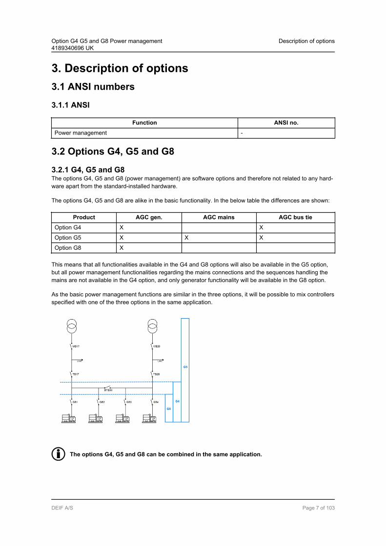
3.2.1 G4, G5 and G8The options G4, G5 and G8 (power management) are software options and therefore not related to any hard-ware apart from the standard-installed hardware.
The options G4, G5 and G8 are alike in the basic functionality. In the below table the differences are shown:
Product AGC gen. AGC mains AGC bus tie
Option G4 X X
Option G5 X X X
Option G8 X
This means that all functionalities available in the G4 and G8 options will also be available in the G5 option,but all power management functionalities regarding the mains connections and the sequences handling themains are not available in the G4 option, and only generator functionality will be available in the G8 option.
As the basic power management functions are similar in the three options, it will be possible to mix controllersspecified with one of the three options in the same application.
The options G4, G5 and G8 can be combined in the same application.
Option G4 G5 and G8 Power management4189340696 UK
Description of options
DEIF A/S Page 7 of 103

A number of AGC units are being used in the power management application, i.e. one for each mains breakerand tie breaker (AGC mains unit), if installed, one for each bus tie breaker (AGC bus tie unit) and one foreach generator (AGC generator unit). All units communicate by means of an internal CANbus connection.
The AGC mains unit includes the power management option and can therefore only be used with option G5applications. The generator AGC unit must be specified with either option G4, G5 or G8, because this unitcan be used in single genset applications and in power management applications.
Option G4 G5 and G8 Power management4189340696 UK
Description of options
DEIF A/S Page 8 of 103

3.3 Terminal description
3.3.1 Description of terminalsThe CANbus interface for the internal communication between AGC units in a G4/G5/G8 application is placedon the engine interface PCB in slot #7.
Term. Function Technical data Description
98 +12/24V DC 12/24V DC +/-30% DC power supply/common for 118
99 0V DC
100 MPU input 2-70V AC/10-10.000 Hz Magnetic pick-up
101 MPU GND
102 A 0(4)-20 mADigitalPt100Pt1000VDO0-40V DC
Multi-input 1
103 B
104 C
105 A Multi-input 2
106 B
107 C
108 A Multi-input 3
109 B
110 C
111 Com. Common Common for terminals 112-117
112 Digital input 112 Optocoupler Configurable
113 Digital input 113 Optocoupler Configurable
114 Digital input 114 Optocoupler Configurable
115 Digital input 115 Optocoupler Ext. engine failure/configurable
116 Digital input 116 Optocoupler Start enable/configurable
117 Digital input 117 Optocoupler Running feedback/configurable
118 Digital input 118 Optocoupler Emergency stop and common for 119 and 120
119 NO Relay24V DC/5 A Run coil
120 NO Relay24V DC/5 A Start prepare
121 Com. Relay250V AC/8 A Crank (starter)
122 NO
123 Com. Relay24V DC/5 A Stop coil w/wire failure detection
124 NO
A1 CAN-H CANbus interface A
A2 GND
A3 CAN-L
B1 CAN-H CANbus interface B
B2 GND
Option G4 G5 and G8 Power management4189340696 UK
Description of options
DEIF A/S Page 9 of 103

Term. Function Technical data Description
B3 CAN-L
3.4 Breaker feedbacks
3.4.1 Generator breakerThe feedbacks of the generator breaker must always be connected (terminals 26 and 27).
3.4.2 Mains breaker (MB) feedback
MB present: The feedbacks of the mains breaker must always be connected (terminals 24 and 25).MB not present: Selected in the application configuration (USW).
When no MB is represented, the MB open and close relays together with the inputs for MBopen and close feedbacks (terminals 24 and 25) will be configurable.
3.4.3 Tie breaker (TB)
TB present: The feedbacks of the tie breaker must always be connected (terminals 26 and 27).TB not present: Selected in the application configuration (USW)
When no TB is represented, the TB open and close relays together with the inputs for TB openand close feedbacks (terminals 26 and 27) will be configurable.
Option G4 G5 and G8 Power management4189340696 UK
Description of options
DEIF A/S Page 10 of 103

3.5 Wiring diagrams
3.5.1 DiagramsThe following diagrams show examples with three AGC units connected, e.g. one AGC mains and two gener-ator AGC units.
Multi-line 2
CANbus interface 1
A1 A2 A3
H GND L
Multi-line 2
CANbus interface 1
A1 A2 A3
H GND L
Multi-line 2
CANbus interface 1
A1 A2 A3
H GND L
120 Ω 120 Ω
Multi-line 2
CANbus interface 2
B1 B2 B3
H GND L
Multi-line 2
CANbus interface 2
B1 B2 B3
H GND L
Multi-line 2
CANbus interface 2
B1 B2 B3
H GND L
120 Ω 120 Ω
For distances above 300 metres we recommend to use a CAN to fibre converter.
Do not connect the cable shield to the GND terminal of the AGC units.
Option G4 G5 and G8 Power management4189340696 UK
Description of options
DEIF A/S Page 11 of 103

4. Functional description4.1 Power management functions
4.1.1 Description of functionsIn the following chapter, the power management functions of the AGC are listed.
Plant modes: Island mode (no mains unit) Automatic Mains Failure (needs mains unit) Fixed power/base load (needs mains unit) Peak shaving (needs mains unit) Load takeover (needs mains unit) Mains power export (needs mains unit)
Display: Mains unit display showing mains breaker and tie breaker Generator unit showing generator and generator breaker
Power management functions: Load-dependent start/stop Priority selection
Manual Running hours Fuel optimisation
Ground relay control ATS control Safety stop (fail class = trip and stop) Load management Multiple mains support Secured mode Quick setup/broadcast Base load Heavy consumer (HC) Asymmetric load sharing (LS) Common PF control CAN flags
Please refer to the Designer’s Reference Handbook for standard functions not relating to thepower management option.
Option G4 G5 and G8 Power management4189340696 UK
Functional description
DEIF A/S Page 12 of 103

4.2 Terminal strip overview
4.2.1 AGC generator unit
Option G4 G5 and G8 Power management4189340696 UK
Functional description
DEIF A/S Page 13 of 103

Option G4 G5 and G8 Power management4189340696 UK
Functional description
DEIF A/S Page 14 of 103

4.2.2 AGC mains unit
Option G4 G5 and G8 Power management4189340696 UK
Functional description
DEIF A/S Page 15 of 103

Option G4 G5 and G8 Power management4189340696 UK
Functional description
DEIF A/S Page 16 of 103

4.2.3 AGC bus tie unit
Option G4 G5 and G8 Power management4189340696 UK
Functional description
DEIF A/S Page 17 of 103

Option G4 G5 and G8 Power management4189340696 UK
Functional description
DEIF A/S Page 18 of 103

4.3 Applications
4.3.1 Application possibilitiesThe options G4 and G5 can be used for the applications listed in the table below. The option G8 alone canonly be used for an island application with DG units.
Application Drawing below Comment
Island operation Island mode plant Multiple gensets
Automatic Mains Failure Parallel with 1-16 mains No back synchronising
Automatic Mains Failure Parallel with 1-16 mains With back synchronising
Automatic Mains Failure ATS plant, multiple start Multiple start system
Automatic Mains Failure ATS plant, mains unit Mains unit installed
Fixed power Parallel Also called base load1-16 mains units
Mains power export Parallel 1-16 mains units
Load takeover Parallel 1-16 mains units
Peak shaving Parallel 1-16 mains units
Refer to the Designer’s Reference Handbook for description of the individual genset modes.
Regarding AC and DC connections for the individual applications, please refer to the Installa-tion Instructions.
Option G4 G5 and G8 Power management4189340696 UK
Functional description
DEIF A/S Page 19 of 103

4.3.2 Island operation plantIn an application where up to 16 gensets are installed, the AGC will automatically operate in an island modewith load-dependent starting and stopping.
G
Generator
breaker
(GB 1)
Diesel generator set 1
Busbar
G
Generator
breaker
(GB 2)
Diesel generator set 2
CANbus
Controller
Display 1
Controller
Display 2
If a mains unit is installed and connected (e.g. for preparing future requirements to the application), the islandmode operation is selected in the mains unit.
Option G4 G5 and G8 Power management4189340696 UK
Functional description
DEIF A/S Page 20 of 103
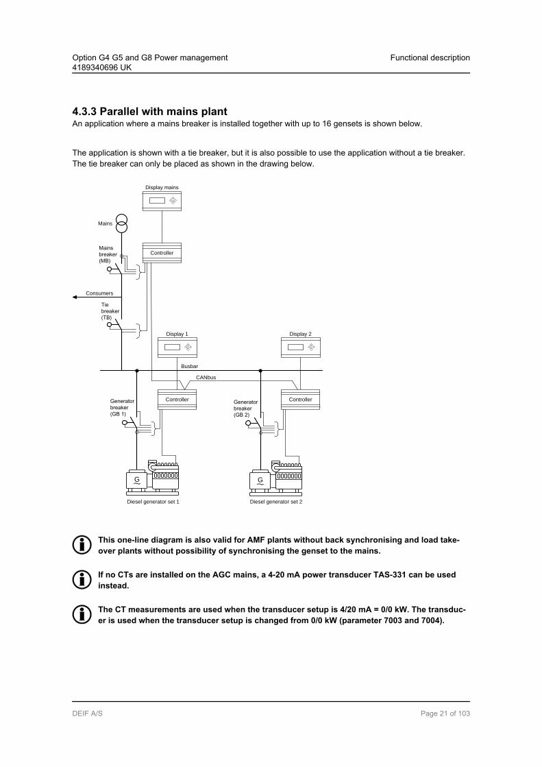
4.3.3 Parallel with mains plantAn application where a mains breaker is installed together with up to 16 gensets is shown below.
The application is shown with a tie breaker, but it is also possible to use the application without a tie breaker.The tie breaker can only be placed as shown in the drawing below.
G
Generator
breaker
(GB 1)
Diesel generator set 1
Busbar
G
Generator
breaker
(GB 2)
Diesel generator set 2
CANbus
Tie
breaker
(TB)
Mains
breaker
(MB)
Mains
Consumers
Controller
Display 1
Controller
Display 2
Controller
Display mains
This one-line diagram is also valid for AMF plants without back synchronising and load take-over plants without possibility of synchronising the genset to the mains.
If no CTs are installed on the AGC mains, a 4-20 mA power transducer TAS-331 can be usedinstead.
The CT measurements are used when the transducer setup is 4/20 mA = 0/0 kW. The transduc-er is used when the transducer setup is changed from 0/0 kW (parameter 7003 and 7004).
Option G4 G5 and G8 Power management4189340696 UK
Functional description
DEIF A/S Page 21 of 103
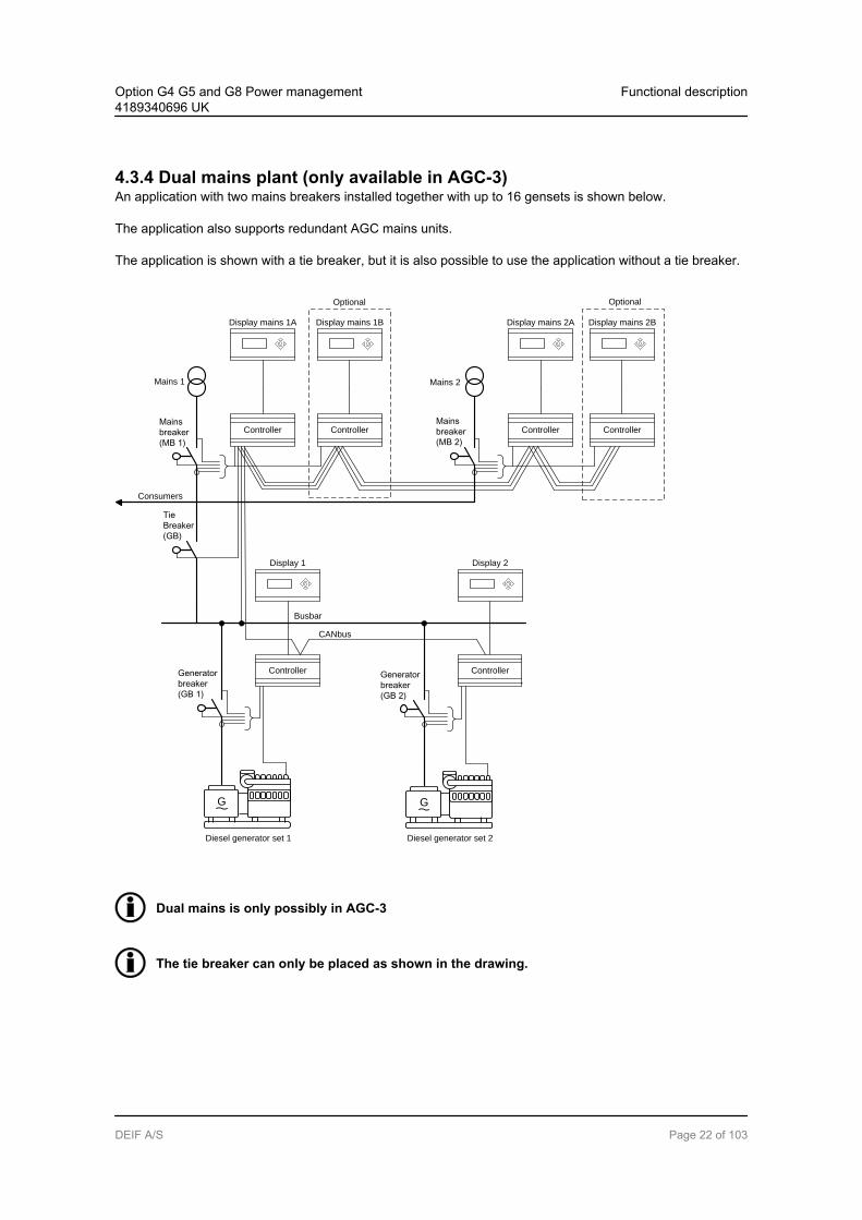
4.3.4 Dual mains plant (only available in AGC-3)An application with two mains breakers installed together with up to 16 gensets is shown below.
The application also supports redundant AGC mains units.
The application is shown with a tie breaker, but it is also possible to use the application without a tie breaker.
G
Generator
breaker
(GB 1)
Diesel generator set 1
Busbar
G
Generator
breaker
(GB 2)
Diesel generator set 2
CANbus
Tie
Breaker
(GB)
Mains
breaker
(MB 1)
Mains 1
Consumers
Mains
breaker
(MB 2)
Mains 2
Optional Optional
Controller
Display 1
Controller
Display 2
Controller
Display mains 1B
Controller
Display mains 2A
Controller
Display mains 2B
Controller
Display mains 1A
Dual mains is only possibly in AGC-3
The tie breaker can only be placed as shown in the drawing.
Option G4 G5 and G8 Power management4189340696 UK
Functional description
DEIF A/S Page 22 of 103
In this application it will not be possible to synchronise the tie breaker.
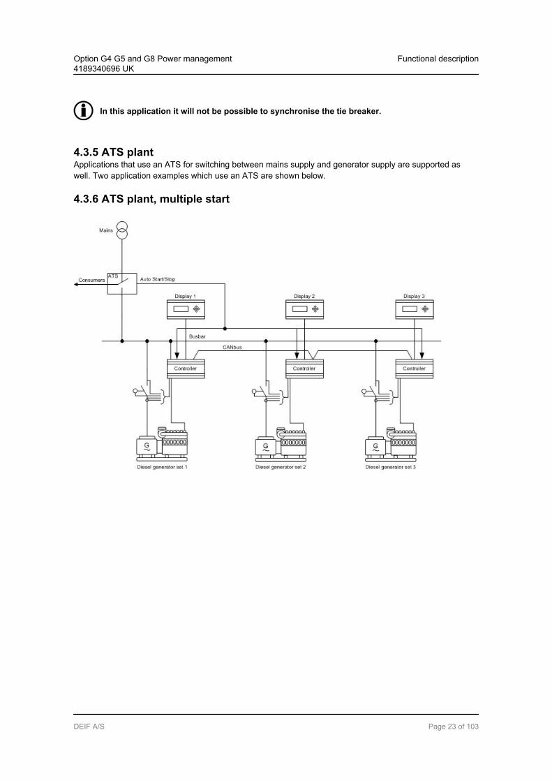
4.3.5 ATS plantApplications that use an ATS for switching between mains supply and generator supply are supported aswell. Two application examples which use an ATS are shown below.
4.3.6 ATS plant, multiple start
Option G4 G5 and G8 Power management4189340696 UK
Functional description
DEIF A/S Page 23 of 103

4.3.7 ATS plant, mains unit
Display
Tie
Breaker
(TB)
Mains
Consumers
Controller
G
Diesel generator set 3
Controller
Display 3
G
Diesel generator set 1
Busbar
G
Diesel generator set 2
CANbus
Controller
Display 1
Controller
Display 2
ATSON/OFF
Mains okay
Option G4 G5 and G8 Power management4189340696 UK
Functional description
DEIF A/S Page 24 of 103

4.3.8 Multiple mainsAn example of a multiple mains plant is shown below. This is just an example; please refer to the chapter onmultiple mains for further information about the possible combinations.
G
Generator
breaker
(GB 1)
Diesel generator set 1
Busbar
G
Generator
breaker
(GB 2)
Diesel generator set 2
CANbus
Tie
breaker
(TB 17)
Mains
breaker
(MB 17)
Mains 17
Consumers
BTB 33
G
Generator
breaker
(GB 3)
Diesel generator set 3
BUSBAR
G
Generator
breaker
(GB 4)
Diesel generator set 4
CANBUS
Tie
breaker
TB 18)
Mains
breaker
(MB 18)
Mains 18
Consumers
Controller
Display 1
Controller
Display 2
Controller
Display 3
Controller
Display BTB 33
Controller
Display 4
Controller
Display mains 17
Controller
Display mains 18
Option G4 G5 and G8 Power management4189340696 UK
Functional description
DEIF A/S Page 25 of 103
5. Display units5.1 DU for option G5
5.1.1 Option G5 displaysThree displays exist for the option G5.
See the Designer’s Reference Handbook or the Operator’s Manual for detailed informationabout push-button functions and LED indication.
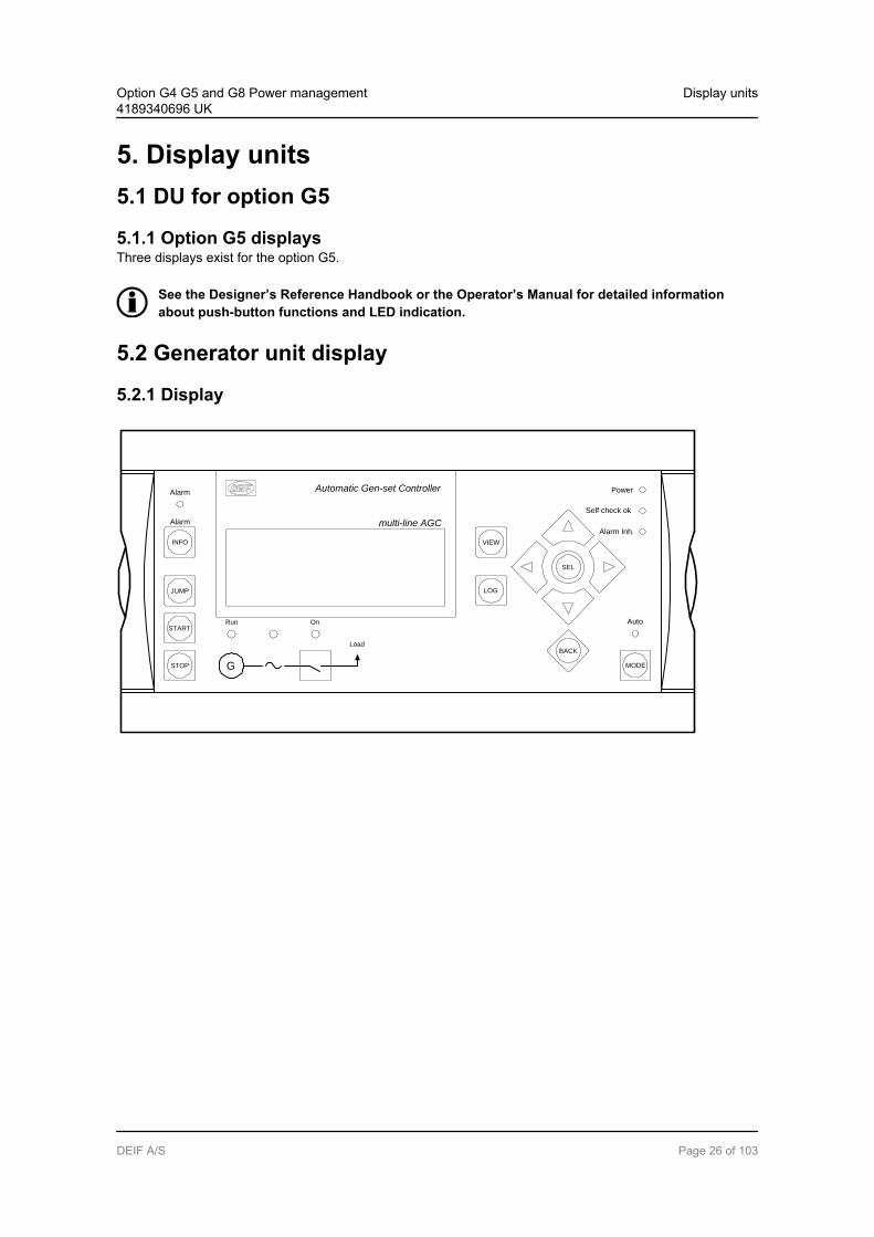
5.2 Generator unit display
5.2.1 Display
Automatic Gen-set Controller
multi-line AGC
VIEW
LOG
Auto
Alarm Inh.
Self check ok
Power
SEL
BACK
MODE
JUMP
START
INFO
STOP
Alarm
Alarm
OnRun
G
Load
Option G4 G5 and G8 Power management4189340696 UK
Display units
DEIF A/S Page 26 of 103

5.3 Mains unit display
5.3.1 Display
Automatic Gen-set Controller
VIEW
LOG
Auto
Alarm Inh.
Self check ok
Power
SEL
BACK
MODE
JUMP
START
INFO
STOP
Alarm
Alarm
multi-line AGC MAINS
On On
Load
5.4 BTB unit display
5.4.1 Display
Automatic Gen-set Controller
multi-line AGC BUS TIE
VIEW
LOG
Auto
Alarm Inh.
Self check ok
Power
SEL
BACK
On
INFO
JUMP
Alarm
Alarm
MODE
Option G4 G5 and G8 Power management4189340696 UK
Display units
DEIF A/S Page 27 of 103
6. Power management setup6.1 Initial power management setup
6.1.1 How to set upThe AGC is set up using the display and the PC utility software.
6.1.2 Display setupEnter the menu 9100 using the JUMP push-button. Select one of the following AGC types:
1. Mains unit2. DG unit3. BTB unit
When this setting is adjusted, the device returns to factory settings! Therefore this must bechanged prior to other adjustments.
Enter the menu 9170 using the JUMP push-button. Select "CAN protocol 2" for a multi mains functionality.Select "CAN protocol 1" for dual mains or single applications.
An alarm appears if CAN protocol 2 is needed.
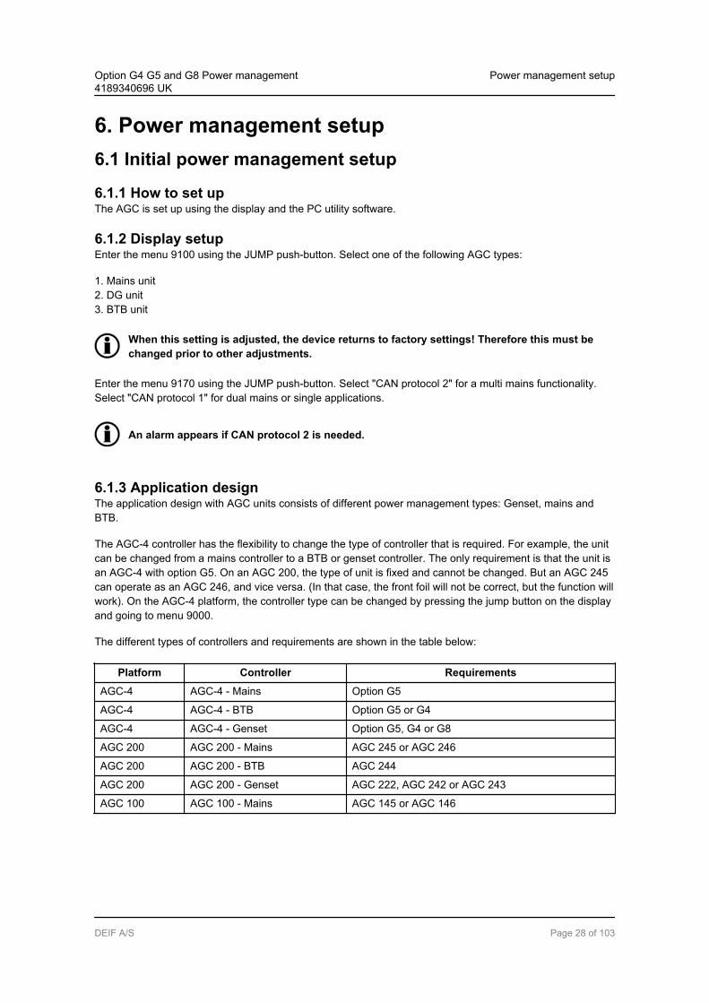
6.1.3 Application designThe application design with AGC units consists of different power management types: Genset, mains andBTB.
The AGC-4 controller has the flexibility to change the type of controller that is required. For example, the unitcan be changed from a mains controller to a BTB or genset controller. The only requirement is that the unit isan AGC-4 with option G5. On an AGC 200, the type of unit is fixed and cannot be changed. But an AGC 245can operate as an AGC 246, and vice versa. (In that case, the front foil will not be correct, but the function willwork). On the AGC-4 platform, the controller type can be changed by pressing the jump button on the displayand going to menu 9000.
The different types of controllers and requirements are shown in the table below:
Platform Controller Requirements
AGC-4 AGC-4 - Mains Option G5
AGC-4 AGC-4 - BTB Option G5 or G4
AGC-4 AGC-4 - Genset Option G5, G4 or G8
AGC 200 AGC 200 - Mains AGC 245 or AGC 246
AGC 200 AGC 200 - BTB AGC 244
AGC 200 AGC 200 - Genset AGC 222, AGC 242 or AGC 243
AGC 100 AGC 100 - Mains AGC 145 or AGC 146
Option G4 G5 and G8 Power management4189340696 UK
Power management setup
DEIF A/S Page 28 of 103
Be aware that when you change the unit type in menu 9000, all settings will be changed back todefault.
The power management communication between the units is configured through the utility software. Thepower management communication is CANbus communication, and, consequently, it must follow the stand-ards for CANbus communication.
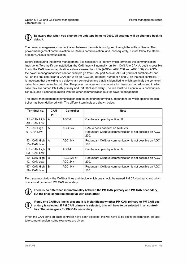
Before configuring the power management, it is necessary to identify which terminals the communicationlines go to. To simplify the installation, the CAN lines will normally run from CAN A to CAN A, but it is possibleto mix the CAN lines on application software newer than 4.5x (AGC-4, AGC 200 and AGC 100). On AGCs,the power management lines can for example go from CAN port A on an AGC-4 (terminal numbers A1 andA3) on the first controller to CAN port A on an AGC 200 (terminal numbers 7 and 9) on the next controller. Itis important that the wiring is a daisy chain connection and that it is identified to which terminals the communi-cation bus goes on each controller. The power management communication lines can be redundant, in whichcase they are named PM CAN primary and PM CAN secondary. The line must be a continuous communica-tion bus, and it cannot be mixed with the other communication bus for power management.
The power management communication can be on different terminals, dependent on which options the con-troller has been delivered with. The different terminals are shown below:
Terminal no. CANport
Controller Note
A1 - CAN HighA3 - CAN Low
A AGC-4 Can be occupied by option H7.
7 - CAN High9 - CAN Low
A AGC 24x CAN A does not exist on AGC 22x.Redundant CANbus communication is not possible on AGC200.
53 - CAN High55 - CAN Low
A AGC 14x Redundant CANbus communication is not possible on AGC100.
B1 - CAN HighB3 - CAN Low
B AGC-4 Can be occupied by option H7.
10 - CAN High12 - CAN Low
B AGC 22x orAGC 24x
Redundant CANbus communication is not possible on AGC200.
57 - CAN High59 - CAN Low
B AGC 14x Redundant CANbus communication is not possible on AGC100.
First, you must follow the CANbus lines and decide which one should be named PM CAN primary, and whichone should be named PM CAN secondary.
There is no difference in functionality between the PM CAN primary and PM CAN secondary,but the lines cannot be mixed up with each other.
If only one CANbus line is present, it is insignificant whether PM CAN primary or PM CAN sec-ondary is selected. If PM CAN primary is selected, this will have to be selected in all control-lers. The same goes for PM CAN secondary.
When the CAN ports on each controller have been selected, this will have to be set in the controller. To facili-tate comprehension, some examples are given.
Option G4 G5 and G8 Power management4189340696 UK
Power management setup
DEIF A/S Page 29 of 103

Example with AGC-4 units:
G
Diesel generator set 1
Busbar
CANbus
TB 17
Load
MB17
AGC4
G
Diesel generator set 2
BTB 33
AGC4
TB 18
Load
MB18
AGC4
AGC4
AGC4
GB 1 GB 2
In this example, the application consists solely of AGC-4 units. The application is an H-coupling with twomains, two gensets and one BTB. The application only has one CANbus line between the units. The CANbusline goes to the terminal numbers shown in the table below:
Controller Terminal no. CAN port CAN protocol
Genset 1 - AGC-4 A1 and A3 A PM CAN primary
Genset 2 - AGC-4 A1 and A3 A PM CAN primary
Mains 17 - AGC-4 A1 and A3 A PM CAN primary
Mains 18 - AGC-4 A1 and A3 A PM CAN primary
BTB 33 - AGC-4 A1 and A3 A PM CAN primary
It is now possible to select whether the CANbus line should be named PM CAN primary or PM CAN secon-dary. It does not make a difference which one is selected when the application only has one CANbus line, aslong as it is the same in all controllers. In this example, PM CAN primary is selected. It is then required to goto parameter 7840 in all controllers and set the corresponding CAN port to PM CAN primary.
Option G4 G5 and G8 Power management4189340696 UK
Power management setup
DEIF A/S Page 30 of 103

It is also possible to mix the CAN ports on the AGC-4, but only on controllers with newer software (4.5x.x ornewer). In this way, it will be possible to make an application where the CAN lines are as shown in the tablebelow:
Controller Terminal no. CAN port CAN protocol
Genset 1 - AGC-4 A1 and A3 A PM CAN secondary
Genset 2 - AGC-4 B1 and B3 B PM CAN secondary
Mains 17 - AGC-4 A1 and A3 A PM CAN secondary
Mains 18 - AGC-4 B1 and B3 B PM CAN secondary
BTB 33 - AGC-4 A1 and A3 A PM CAN secondary
The order of the CAN ports is not important, as long as the settings in the controllers are correct. But it isalways recommended to use the same CAN port on each controller. This can be helpful when troubleshoot-ing, and it can also facilitate commissioning. In the last example, it does not matter whether PM CAN primaryor PM CAN secondary is selected, the function will be the same. It is only important that it is PM CAN primaryin all controllers or PM CAN secondary in all controllers.
Example with AGC 200 units:
G
Diesel generator set 1
Busbar
CANbus
TB 17
Load
MB17
G
Diesel generator set 2
BTB 33
TB 18
Load
MB18
AGC 245/246 AGC 245/246
AGC 244
AGC 242/243 AGC 242/243
GB 1 GB 2
Option G4 G5 and G8 Power management4189340696 UK
Power management setup
DEIF A/S Page 31 of 103
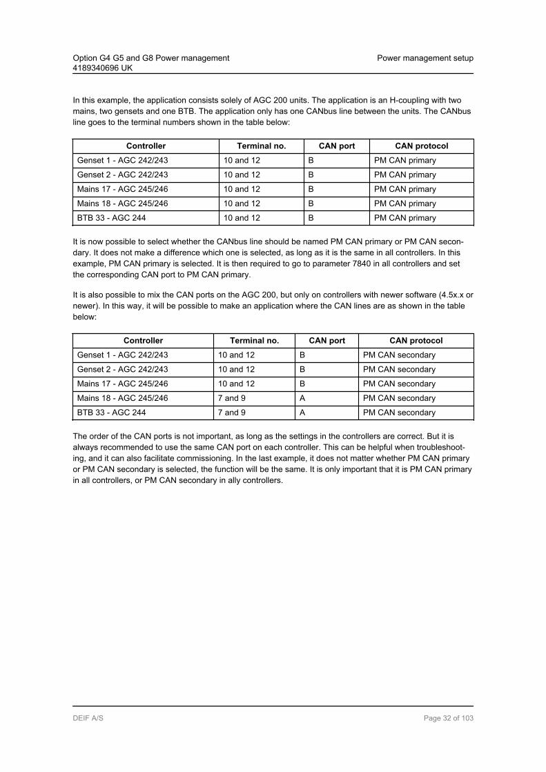
In this example, the application consists solely of AGC 200 units. The application is an H-coupling with twomains, two gensets and one BTB. The application only has one CANbus line between the units. The CANbusline goes to the terminal numbers shown in the table below:
Controller Terminal no. CAN port CAN protocol
Genset 1 - AGC 242/243 10 and 12 B PM CAN primary
Genset 2 - AGC 242/243 10 and 12 B PM CAN primary
Mains 17 - AGC 245/246 10 and 12 B PM CAN primary
Mains 18 - AGC 245/246 10 and 12 B PM CAN primary
BTB 33 - AGC 244 10 and 12 B PM CAN primary
It is now possible to select whether the CANbus line should be named PM CAN primary or PM CAN secon-dary. It does not make a difference which one is selected, as long as it is the same in all controllers. In thisexample, PM CAN primary is selected. It is then required to go to parameter 7840 in all controllers and setthe corresponding CAN port to PM CAN primary.
It is also possible to mix the CAN ports on the AGC 200, but only on controllers with newer software (4.5x.x ornewer). In this way, it will be possible to make an application where the CAN lines are as shown in the tablebelow:
Controller Terminal no. CAN port CAN protocol
Genset 1 - AGC 242/243 10 and 12 B PM CAN secondary
Genset 2 - AGC 242/243 10 and 12 B PM CAN secondary
Mains 17 - AGC 245/246 10 and 12 B PM CAN secondary
Mains 18 - AGC 245/246 7 and 9 A PM CAN secondary
BTB 33 - AGC 244 7 and 9 A PM CAN secondary
The order of the CAN ports is not important, as long as the settings in the controllers are correct. But it isalways recommended to use the same CAN port on each controller. This can be helpful when troubleshoot-ing, and it can also facilitate commissioning. In the last example, it does not matter whether PM CAN primaryor PM CAN secondary is selected, the function will be the same. It is only important that it is PM CAN primaryin all controllers, or PM CAN secondary in ally controllers.
Option G4 G5 and G8 Power management4189340696 UK
Power management setup
DEIF A/S Page 32 of 103

Example with AGC-4 and AGC 100 units:
G
Diesel generator set 1
Busbar
CANbus
TB 17
Load
MB17
G
Diesel generator set 2
BTB 33
TB 18
Load
MB18
AGC 145/146 AGC 145/146
AGC4
AGC4 AGC4
GB 1 GB 2
In this example, the application consists of a mix of AGC 100 units and AGC-4 units. The application is an H-coupling with two mains, two gensets and one BTB. The application only has one CANbus line between theunits. The CANbus line goes to the terminal numbers shown in the table below:
Controller Terminal no. CAN port CAN protocol
Genset 1 - AGC-4 B1 and B3 B PM CAN secondary
Genset 2 - AGC-4 B1 and B3 B PM CAN secondary
Mains 17 - AGC 145/146 53 and 55 A PM CAN secondary
Mains 18 - AGC 145/146 53 and 55 A PM CAN secondary
BTB 33 - AGC-4 A1 and A3 A PM CAN secondary
It is now possible to select whether the CANbus line should be named PM CAN primary or PM CAN secon-dary. It does not make a difference which one is selected, as long as it is the same in all controllers. In thisexample, PM CAN secondary is selected. It is then required to go to parameter 7840 in all controllers and setthe corresponding CAN port to PM CAN secondary.
Option G4 G5 and G8 Power management4189340696 UK
Power management setup
DEIF A/S Page 33 of 103
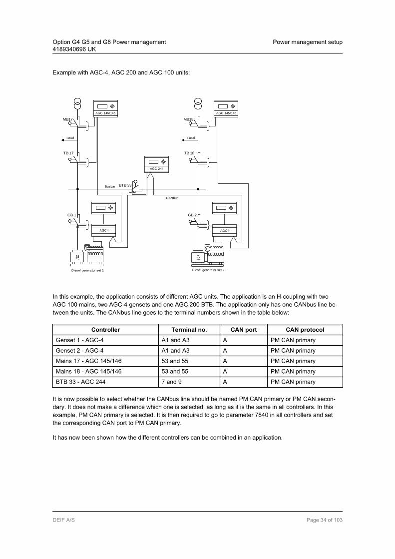
Example with AGC-4, AGC 200 and AGC 100 units:
G
Diesel generator set 1
Busbar
CANbus
TB 17
Load
MB17
G
Diesel generator set 2
BTB 33
TB 18
Load
MB18
AGC 145/146 AGC 145/146
AGC 244
AGC4 AGC4
GB 1 GB 2
In this example, the application consists of different AGC units. The application is an H-coupling with twoAGC 100 mains, two AGC-4 gensets and one AGC 200 BTB. The application only has one CANbus line be-tween the units. The CANbus line goes to the terminal numbers shown in the table below:
Controller Terminal no. CAN port CAN protocol
Genset 1 - AGC-4 A1 and A3 A PM CAN primary
Genset 2 - AGC-4 A1 and A3 A PM CAN primary
Mains 17 - AGC 145/146 53 and 55 A PM CAN primary
Mains 18 - AGC 145/146 53 and 55 A PM CAN primary
BTB 33 - AGC 244 7 and 9 A PM CAN primary
It is now possible to select whether the CANbus line should be named PM CAN primary or PM CAN secon-dary. It does not make a difference which one is selected, as long as it is the same in all controllers. In thisexample, PM CAN primary is selected. It is then required to go to parameter 7840 in all controllers and setthe corresponding CAN port to PM CAN primary.
It has now been shown how the different controllers can be combined in an application.
Option G4 G5 and G8 Power management4189340696 UK
Power management setup
DEIF A/S Page 34 of 103
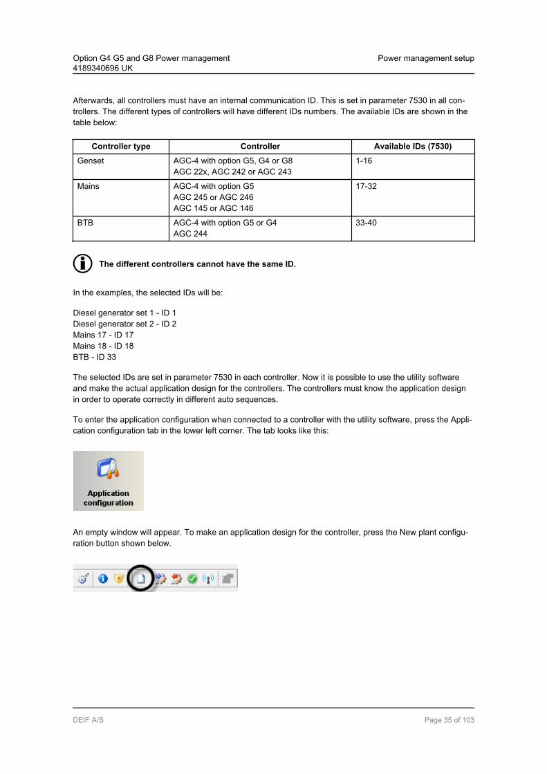
Afterwards, all controllers must have an internal communication ID. This is set in parameter 7530 in all con-trollers. The different types of controllers will have different IDs numbers. The available IDs are shown in thetable below:
Controller type Controller Available IDs (7530)
Genset AGC-4 with option G5, G4 or G8AGC 22x, AGC 242 or AGC 243
1-16
Mains AGC-4 with option G5AGC 245 or AGC 246AGC 145 or AGC 146
17-32
BTB AGC-4 with option G5 or G4AGC 244
33-40
The different controllers cannot have the same ID.
In the examples, the selected IDs will be:
Diesel generator set 1 - ID 1Diesel generator set 2 - ID 2Mains 17 - ID 17Mains 18 - ID 18BTB - ID 33
The selected IDs are set in parameter 7530 in each controller. Now it is possible to use the utility softwareand make the actual application design for the controllers. The controllers must know the application designin order to operate correctly in different auto sequences.
To enter the application configuration when connected to a controller with the utility software, press the Appli-cation configuration tab in the lower left corner. The tab looks like this:
An empty window will appear. To make an application design for the controller, press the New plant configu-ration button shown below.
Option G4 G5 and G8 Power management4189340696 UK
Power management setup
DEIF A/S Page 35 of 103

The Plant options window shown below will appear.
Option G4 G5 and G8 Power management4189340696 UK
Power management setup
DEIF A/S Page 36 of 103

The plant options are described in the table below:
Description Comments
Prod-ucttype
Controller type isselected here.
This function is greyed out if a controller is already connected.
Planttype
Select between Single DG Standard Genset group
plant Genset group
"Standard" should be selected for power management systems.If "Single DG" is selected, the CAN ports for power management communi-cation will be turned off."Genset group plant" and "Genset Group" are only relevant for controllerswith plant management. Plant management is for power plants consisting of17-256 gensets in the same application. Contact [email protected] for fur-ther information.
Appli-cationproper-ties
The application isactivated when itis written to thecontroller.The applicationcan also benamed here.
It can be helpful to give the application a name if the controller is in a plantwhere it will switch between application designs. The controllers are able toswitch between four different application designs. Controllers that are con-nected to each other via the CANbus communication cannot be activated todifferent application designs or numbers.
Bus tieop-tions
The "Wrap bus-bar" option canbe selected here.
Activate this option if the busbar is connected like a ring connection in theplant. When the wrap busbar option is set, it will be shown in the applicationsupervision like this:
Powerman-age-mentCAN
Primary CANSecondary CANPrimary and sec-ondary CANCAN bus off
The CAN protocol selected here should be identical to the settings in theunit. So if PM CAN primary is selected in the units, this must be selected inthe plant settings as well. The setting called primary and secondary CAN isonly used when redundant CANbus communication lines for power manage-ment are present. If this setting is selected and only one line is present, analarm will appear in the display. This alarm cannot be cleared.The setting for CANbus off should only be used if the AGC is in a stand-alone application.
Appli-cationemula-tion
OffBreaker and en-gine cmd. activeBreaker and en-gine cmd. inac-tive
The emulation is started here if the units have option I1.When Breaker and engine cmd. active is set, the units will activate the re-lays and try to communicate with an ECU. If the units are mounted in a realinstallation, the breakers will open/close and the engine start/stop. This willnot happen if the Breaker and engine cmd. inactive is selected. In real instal-lations, the emulation can be used during the commissioning. But when thecommissioning is done, the emulation should be switched off.
When the selections in the plant options window have been made, it is possible to make the application draw-ing in the units.
Now, controllers can be added to the design, and it can be selected which type of breakers is present in theapplication. This is done from the left side of the utility software.
Option G4 G5 and G8 Power management4189340696 UK
Power management setup
DEIF A/S Page 37 of 103

The table below describes the plant configuration options that are shown in the window above.
Option G4 G5 and G8 Power management4189340696 UK
Power management setup
DEIF A/S Page 38 of 103

No. Description
1 Add and delete areas. Adding areas will make the application design/plant bigger.
2 Select which type of power source should be represented in the top of the area. Only mains or dieselgenset can be selected.
3 Set the internal command ID. This ID should correspond to the ID set in the controller.
4 Requires option T1 (critical power). Makes it possible to have redundant controller.
5 Because mains has been selected in the source (no. 2), it is possible to select which type of breakerto use for mains breaker. The options are: Pulse, Externally controlled/ATS no control, ContinuousND, Continuous NE, Compact or none.
6 Because mains has been selected in the source (no. 2), it is possible to select which type of breakerto use for tie breaker. The options are: Pulse, Continuous NE, Compact or none.
7 Select whether the tie breaker should be normally open or normally closed.
8 BTB controllers can be added.
9 The type of breaker that is used for BTB operation. The options are: Pulse, Continuous NE, Compactor Externally controlled. (Externally controlled BTB means that no controller is present. Breaker posi-tion inputs can be made to another controller in the power management system).
10 Set the ID for the specific BTB controller.
11 Select whether the BTB should be normally open or normally closed.
12 If Vdc breaker is selected, the breaker can open and close when there is no voltage on the busbar.If Vac breaker is selected, voltage must be present on the busbar before the breaker can be handled.
13 If the BTB has an under-voltage coil, it is set here.
14 Requires option T1 (critical power). Makes it possible to have redundant controller.
15 Select which type of power source should be represented in the bottom of the area. Only mains ordiesel genset can be selected.
16 Set the internal command ID. This ID should correspond to the ID set in the controller.
17 Requires option T1 (critical power). Makes it possible to have redundant controller.
18 Because diesel genset has been selected in the power source (no. 15), it is possible to select whichtype of breaker to use for generator breaker. The options are: Pulse, Continuous NE or Compact.
Option G4 G5 and G8 Power management4189340696 UK
Power management setup
DEIF A/S Page 39 of 103

The application drawing/design for the example will be like this:
Subsequently, the configuration for the plant must be sent to the units. This can be done by pressing the
Write plant configuration to the device button, which looks like this:
After pressing the button, only the one controller, to which you are connected, knows the actual applicationconfiguration. The application configuration can then be sent from this controller to all the other controllers by
pressing the Broadcast button in the top of the utility software:
If the AGC is to fit into an application with AGC units with older software, this can also be done. But somerestrictions must be fulfilled before the system will work correctly. On older software, the communication lines(CAN protocols) are called CAN A and CAN B. By default, these are set to a CAN port and cannot be switch-ed. In the table below, this is shown for the different controllers.
Option G4 G5 and G8 Power management4189340696 UK
Power management setup
DEIF A/S Page 40 of 103
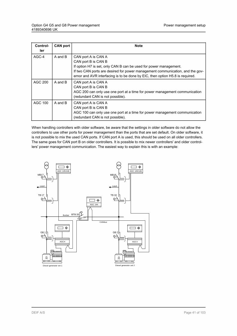
Control-ler
CAN port Note
AGC-4 A and B CAN port A is CAN ACAN port B is CAN BIf option H7 is set, only CAN B can be used for power management.If two CAN ports are desired for power management communication, and the gov-ernor and AVR interfacing is to be done by EIC, then option H5.8 is required.
AGC 200 A and B CAN port A is CAN ACAN port B is CAN BAGC 200 can only use one port at a time for power management communication(redundant CAN is not possible).
AGC 100 A and B CAN port A is CAN ACAN port B is CAN BAGC 100 can only use one port at a time for power management communication(redundant CAN is not possible).
When handling controllers with older software, be aware that the settings in older software do not allow thecontrollers to use other ports for power management than the ports that are set default. On older software, itis not possible to mix the used CAN ports. If CAN port A is used, this should be used on all older controllers.The same goes for CAN port B on older controllers. It is possible to mix newer controllers' and older control-lers' power management communication. The easiest way to explain this is with an example:
G
Diesel generator set 1
Busbar
CANbus
TB 17
Load
MB17
G
Diesel generator set 2
BTB 33
TB 18
Load
MB18
AGC 145/146 AGC 145/146
AGC 244
AGC4 AGC4
GB 1 GB 2
Option G4 G5 and G8 Power management4189340696 UK
Power management setup
DEIF A/S Page 41 of 103

The setup shown above is the same as used in the example earlier. But the controllers now have differentsoftware versions. The CAN ports used are shown in the table below:
Controller Terminal no. CAN port CAN protocol
Genset 1 - AGC-4 (older software) A1 and A3 A CAN A
Genset 2 - AGC-4 (newer software) B1 and B3 B PM CAN primary
Mains 17 - AGC 145/146 (newer software) 57 and 59 B PM CAN primary
Mains 18 - AGC 145/146 (older software) 53 and 55 A CAN A
BTB 33 - AGC 244 (newer software) 7 and 9 A PM CAN primary
Note that all controllers with older software (4.4x or older) use the same CAN port. When the controller witholder software uses CAN port A for power management communication, the setting in the controller with new-er software should be PM CAN primary.
If the controllers with older software had used CAN port B instead, the setting in the controller with newersoftware should be PM CAN secondary.
An overview is shown in the table below:
CAN port on controllerwith older software
CAN port on controller with newersoftware
Setting in controller with newersoftware
A Does not matter PM CAN primary
B Does not matter PM CAN secondary
Option G4 G5 and G8 Power management4189340696 UK
Power management setup
DEIF A/S Page 42 of 103

The AGC-4 is capable of using redundant power management CAN lines. These could be used in an applica-tion like this:
G
Diesel generator set 1
Busbar
CANbus
TB 17
Load
MB17
AGC4
G
Diesel generator set 2
BTB 33
AGC4
TB 18
Load
MB18
AGC4
AGC4
AGC4
GB 1 GB 2
The application shown above consists solely of AGC-4 units with redundant CAN lines for power manage-ment. The controllers are a mix of newer and older software. The CAN lines go to these terminal numbers:
Controller Terminal no. (1) CAN port (1) Terminal no. (2) CAN port (2)
Genset 1 - AGC-4 (older software) A1 and A3 A B1 and B3 B
Genset 2 - AGC-4 (newer software) B1 and B3 B A1 and B3 A
Mains 17 - AGC-4 (newer software) 57 and 59 B A1 and A3 A
Mains 18 - AGC-4 (older software) A1 and A3 A B1 and B3 B
BTB 33 - AGC-4 (newer software) 7 and 9 A A1 and A3 A
Controllers with older software use the same CAN port for each CAN line.
Option G4 G5 and G8 Power management4189340696 UK
Power management setup
DEIF A/S Page 43 of 103

When the controllers are mixed with software and CAN ports, the controllers with the older software deter-mine the settings in parameter 7840 for the controllers with newer software. If the CAN line on the controllerwith older software goes to CAN port A, the setting for the controllers with newer software should be PM CANprimary. The settings from the example are shown below. To facilitate comprehension, the CAN lines are divi-ded into two tables:
Table for CAN line A/PM CAN primary(The table shows which CAN ports should be set to PM CAN primary on the controllers with newer software):
Controller CAN line A/PM CAN primary setting (7840)
Genset 1 - AGC-4 (older software) Not adjustable
Genset 2 - AGC-4 (newer software) B
Mains 17 - AGC-4 (newer software) B
Mains 18 - AGC-4 (older software) Not adjustable
BTB 33 - AGC-4 (newer software) A
Table for CAN line B/PM CAN secondary(The table shows which CAN ports should be set to PM CAN secondary on the controllers with newer soft-ware):
Controller CAN line B/PM CAN secondary setting (7840)
Genset 1 - AGC-4 (older software) Not adjustable
Genset 2 - AGC-4 (newer software) A
Mains 17 - AGC-4 (newer software) A
Mains 18 - AGC-4 (older software) Not adjustable
BTB 33 - AGC-4 (newer software) B
If one of the CAN lines should break, there are alarms related to this which can be helpful when troubleshoot-ing. This is described in the chapter CANbus failure handling.
Option G4 G5 and G8 Power management4189340696 UK
Power management setup
DEIF A/S Page 44 of 103

6.2 CANbus failure handling
6.2.1 CAN failure modeThe system behaviour can be set up in different ways to handle a CAN failure on the CAN controlling thepower management. In menu 7530, it is decided how the power management system will react in case of aCAN failure. There are three selectable modes the controllers should change to in case of a CANbus failure:
1. Manual:If "MANUAL" is selected, all the AGC units will change mode to manual mode. In this way, the regula-tors will have no reaction, and it will not be possible to close any breakers (unless the breakers arealready within the limits for the sync. window or black busbar). Manual mode is not selectable in BTBor mains units.When the wire break on the CAN lines occurs, the regulators will stop immediately, and no further ac-tion will take place. Protections are still active, so if for example a short circuit or an overload occurs,the AGC is still able to make a shutdown or a trip of a breaker.Manual mode can also be described with an example:
G
Diesel generator set 2
AGC4AGC 242/243
G
Diesel generator set 1
Busbar
CANbus
If the wire break occurs before the engine is started, the controller is not allowed to start the engines. Ifmore than two gensets are present in an application and manual is selected, none of the gensets willbe able to loadshare. Only the protections are active.Be aware that when a CANbus failure is present, the risk of blackout is also present, since load shar-ing does not take place in manual mode.
Option G4 G5 and G8 Power management4189340696 UK
Power management setup
DEIF A/S Page 45 of 103

2. Semi-auto:If "SEMI-AUTO" is selected, the AGC units will change to semi-auto mode when a CANbus failurealarm occurs.In semi-auto mode, the regulators in the AGC units are still active. This means that the gensets thatare visible to each other are able to loadshare. This is explained by an example:
G
Diesel generator set 2
AGC4AGC 242/243
G
Diesel generator set 1
Busbar
CANbus
G
Diesel generator set 3
G
Diesel generator set 4
AGC 242/243AGC4
In the diagram above, the CANbus failure is present between genset 2 and genset 3. This means thatgensets 1 and 2 are visible to each other. Gensets 3 and 4 are also visible to each other. Gensets 1and 2 are able to loadshare with each other, and gensets 3 and 4 are able to loadshare with eachother. But there is still a risk of blackout, since it is still possible to overload two of the gensets, whilethe other two are not very loaded.If a CANbus failure occurs when the gensets are stopped, they will not be blocked, and in this way itwill be possible to start them.
If a CANbus failure is present in this situation, it is possible to start two gensets andclose the breaker onto the busbar at the same time! (Not synchronised).
Option G4 G5 and G8 Power management4189340696 UK
Power management setup
DEIF A/S Page 46 of 103
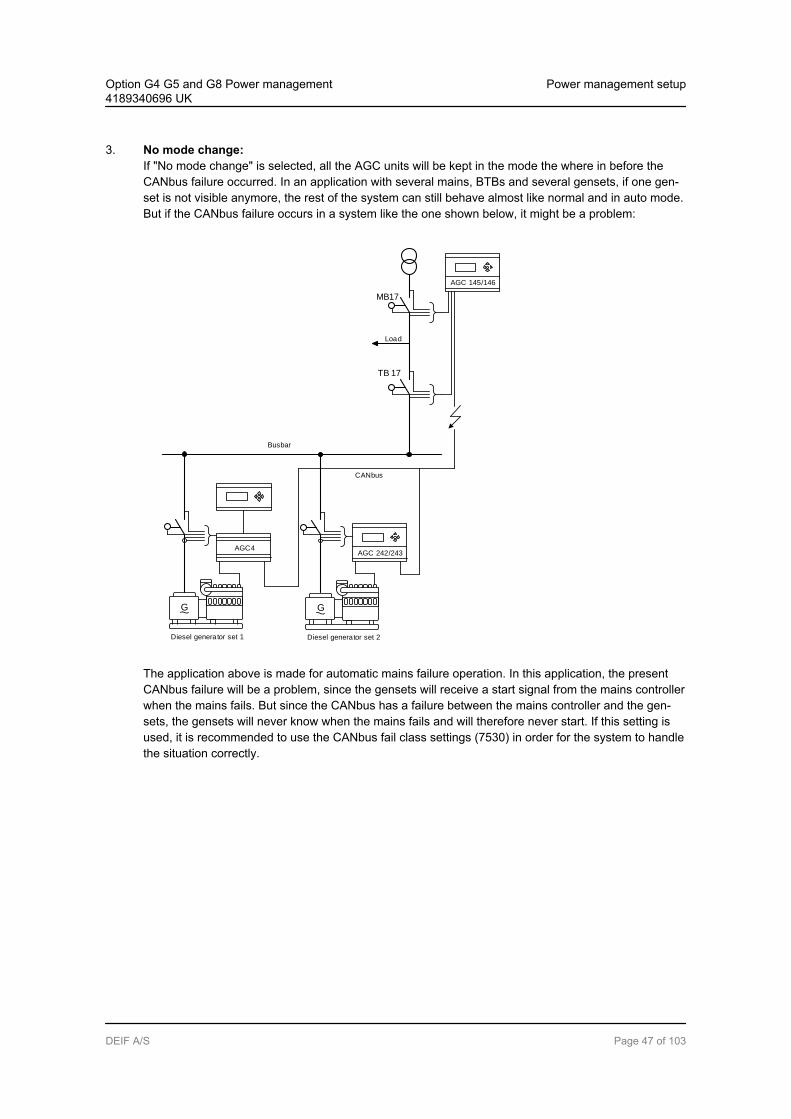
3. No mode change:If "No mode change" is selected, all the AGC units will be kept in the mode the where in before theCANbus failure occurred. In an application with several mains, BTBs and several gensets, if one gen-set is not visible anymore, the rest of the system can still behave almost like normal and in auto mode.But if the CANbus failure occurs in a system like the one shown below, it might be a problem:
G
Diesel generator set 2
AGC4AGC 242/243
G
Diesel generator set 1
Busbar
CANbus
TB 17
Load
MB17
AGC 145/146
The application above is made for automatic mains failure operation. In this application, the presentCANbus failure will be a problem, since the gensets will receive a start signal from the mains controllerwhen the mains fails. But since the CANbus has a failure between the mains controller and the gen-sets, the gensets will never know when the mains fails and will therefore never start. If this setting isused, it is recommended to use the CANbus fail class settings (7530) in order for the system to handlethe situation correctly.
Option G4 G5 and G8 Power management4189340696 UK
Power management setup
DEIF A/S Page 47 of 103

6.2.2 CANbus fail classesThe AGC units have different CANbus alarms, which are triggered in different situations:
Missing all units:Appears only when a controller cannot "see" any other units on the CANbus line. The fail class selectedin parameter 7533 will be executed.
Fatal CAN error:Appears when two or more units are not visible, but one or some units are still visible. The fail class se-lected in parameter 7534 will be executed.
Any DG missing:Appears when only one genset controller is missing. The fail class selected in parameter 7535 will beexecuted.
Any mains missing:Appears when only one mains controller is missing. The fail class selected in parameter 7533 will be exe-cuted. The fail class selected here is also used when a BTB is missing.
6.2.3 CANbus alarmsThe following alarms can be displayed on an AGC unit in case of CANbus communication failures:
CAN ID X P missingThe AGC unit has lost CANbus communication to CAN ID on PM CAN primary.
CAN MAINS X P missingThe AGC unit has lost CANbus communication to mains with ID X on PM CAN primary.
CAN BTB X P missingThe AGC unit has lost CANbus communication to BTB with ID X on PM CAN primary.
CAN ID X S missingThe AGC unit has lost CANbus communication to CAN ID on PM CAN secondary.
CAN MAINS X S missingThe AGC unit has lost CANbus communication to mains with ID X on PM CAN secondary.
CAN BTB X S missingThe AGC unit has lost CANbus communication to BTB with ID X on PM CAN secondary.
CAN setup CH: 784xThe unit can sense power management communication on a CAN port, but the correct protocol is not set.This alarm is also monitoring the CAN setup between engine communication protocol (H5, H7, H13) andCAN port.
For a general description of "Fail class", please refer to the description of fail classes in therelevant chapter in the Designer's Reference Handbook.
Load sharing backup: It is possible to have a backup of the load sharing if the power manage-ment CANbus should fail. This can be done by analogue load sharing.
Option G4 G5 and G8 Power management4189340696 UK
Power management setup
DEIF A/S Page 48 of 103

6.3 Remove and add units
6.3.1 Remove a unit from the power management systemIf one or more units have to be taken out of the power management system, the following steps can be per-formed.
The first step is to remove the auxiliary supply of the AGC. This means that a CANbus alarm occurs on theother AGC units. These alarms appear on ID 1 in a 2 DG plant where ID 2 is powered down:
Alarm Functioning unit (ID 1)
System alarm CAN ID 2 P/S missing
Menu 7533 Missing all units
Menu 7535 Any DG missing
The mode changes according to the setting in CAN failure mode (7532).
The alarms will be present as long as the failure is present. A reconfiguration of the power plant is required toremove the alarms. The reconfiguration can be done in two ways: By means of quick setup or by means ofthe utility software.
Please refer to the chapter Application design for instructions for using the utility software todesign an application configuration.
The application can also be reconfigured from the quick setup menu (9180). The quick setup should only beused for small applications. It is also normally used for small applications for rental gensets. If the quick setupis used, utility software is not required.
For more details, please refer to the chapter Quick setup.
6.3.2 Add a unit to the power management systemIf the same 2 DG plants as mentioned earlier are used, and the controller with ID 2 is switched to a brandnew controller with default settings, both controllers will get two alarms: "Duplicate CAN ID" and "Appl. haz-ard".
The "Duplicate CAN ID" alarm indicates that there are at lease two units with the same internal communica-tion ID (7530). These numbers cannot be similar, since the system cannot handle this correctly.
The "Appl. Hazard" alarm indicates that not all controllers in the system have matching "application configura-tions". The system will not be able to operate correctly, because there is a mismatch between the units in thesystem. To clear this alarm, it is required to go to the application configuration in the utility software or to usethe quick setup to reconfigure the application in the controllers.
If, instead, the DG2 has been switched off and then switched on again, the alarms will disappear, but this isonly because the CAN IDs (7530) and the application configuration were correct before the unit was switchedoff.
Option G4 G5 and G8 Power management4189340696 UK
Power management setup
DEIF A/S Page 49 of 103
6.4 Quick setup
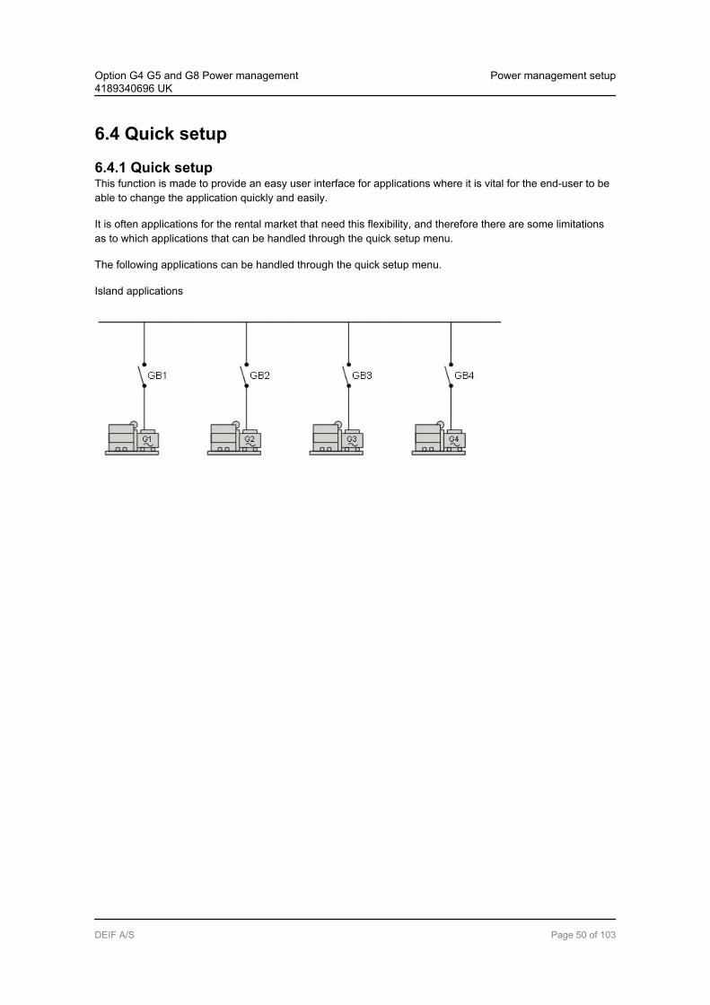
6.4.1 Quick setupThis function is made to provide an easy user interface for applications where it is vital for the end-user to beable to change the application quickly and easily.
It is often applications for the rental market that need this flexibility, and therefore there are some limitationsas to which applications that can be handled through the quick setup menu.
The following applications can be handled through the quick setup menu.
Island applications
Option G4 G5 and G8 Power management4189340696 UK
Power management setup
DEIF A/S Page 50 of 103
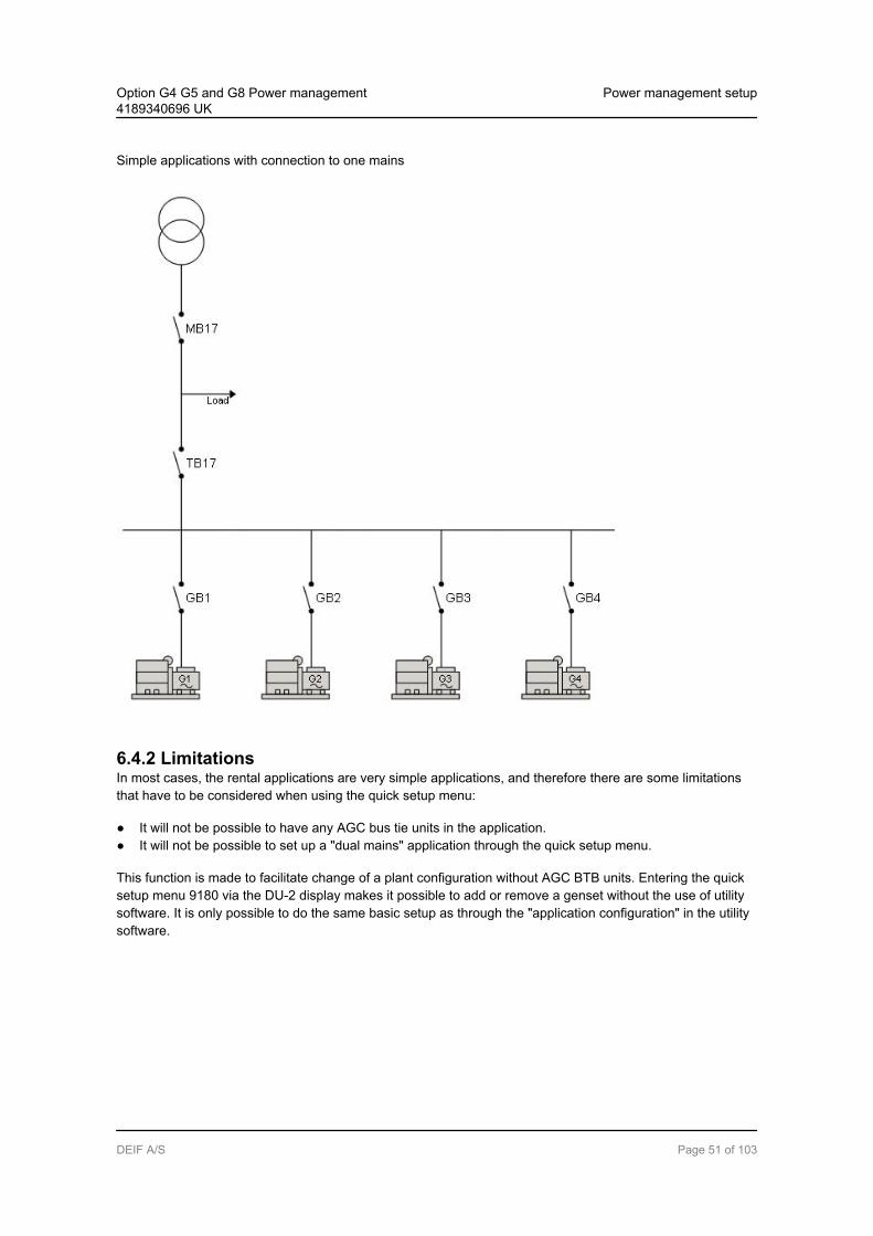
Simple applications with connection to one mains
6.4.2 LimitationsIn most cases, the rental applications are very simple applications, and therefore there are some limitationsthat have to be considered when using the quick setup menu:
It will not be possible to have any AGC bus tie units in the application. It will not be possible to set up a "dual mains" application through the quick setup menu.
This function is made to facilitate change of a plant configuration without AGC BTB units. Entering the quicksetup menu 9180 via the DU-2 display makes it possible to add or remove a genset without the use of utilitysoftware. It is only possible to do the same basic setup as through the "application configuration" in the utilitysoftware.
Option G4 G5 and G8 Power management4189340696 UK
Power management setup
DEIF A/S Page 51 of 103

The functions marked with clear text in the screen shots below can be accessed through the quick setupmenu.
6.5 9180 Quick setup
6.5.1 9180 Quick setup9181 Mode
OFF: When the mode menu is set to "OFF", the existing application that is about to have this gensetincluded will not look for this new genset. This will give the operator time to connect all wiringand to do the basic setup of the genset.
Option G4 G5 and G8 Power management4189340696 UK
Power management setup
DEIF A/S Page 52 of 103

SetupPlant:
When the mode menu is set to "Setup Plant", the new AGC will receive the application config-uration from the other units in the plant. The new AGC will then notify the rest of the applica-tion that a new ID is available on the line. If the ID of the new AGC already exists, the newAGC will – based on the ID numbers in the application configuration – have the highest ID + 1assigned. This new ID will then be included in the application configuration in all the otherAGCs. During this process, the existing application will be able to continue running and will notbe affected by the upgrade of the system.
The new AGC will automatically go to block mode to ensure that it is in a safe mode. When thesetup is done, the end-user must decide in which running mode the added genset is to run.
If there are already 16 gensets on the CAN line and a new AGC tries to connect to the plant, analarm text, "No IDs available", will appear.
SetupStand-alone:
When the mode menu is set to "Setup Stand-alone", the AGC will change the applicationconfiguration, so it will no longer be a part of the application. When the ID is removed fromthe application, the new application will be broadcasted to the other AGCs. The IDs of theexisting gensets in the application will maintain their ID, as a rearrangement could lead tounnecessary starting and stopping of the gensets.
If the genset that is to be removed is running, it will not be possible/allowed to continue theprocess until the genset has stopped. If it is attempted to disconnect, an info text, "Quick set-up error", will appear.
If "Setup Stand-alone" is activated when the genset is running, an info text, "Quick setup er-ror", will appear.
If an AGC BTB is detected in the application, an indicating alarm, "Appl. not possible", will ap-pear.
Change of setup from standard to single DG unit: When disconnecting a standard AGC unit ina system, it is important to change the menu 9181, plant setup. After disconnecting, the AGCunit will become a single DG.
6.5.2 9190 Application broadcastThis function makes it possible to broadcast an application over the CAN line from one AGC to all unitspresent in the application. It takes one operation to activate the broadcast function. It can be done in twoways:
1. By sending the application.2. By sending the application and activating it.
Menu 9191 Enable
OFF: When it is set to OFF, no broadcast will be made.
Broadcast: Broadcast of the selected application in menu 9192 will be sent to the units in theapplication.
Option G4 G5 and G8 Power management4189340696 UK
Power management setup
DEIF A/S Page 53 of 103

Broadcast + Acti-vate
Broadcast is activated and the application in menu 9192 will be broadcasted andactivated in all units.
Menu 9192 ApplicationApplications 1-4 can be drawn in the utility software.
The following pop-up windows in the utility software will guide you through the broadcast.
Option G4 G5 and G8 Power management4189340696 UK
Power management setup
DEIF A/S Page 54 of 103
7. Power management functions7.1 Command unit
7.1.1 Command unitThe power management system is a multi-master system. In a multi-master system, the available generatorunits automatically perform the power management control. This means that the system never depends ononly one master unit.
If for instance one unit ID is disabled, and this was the command unit, then the next available unit will takeover the command functions.
The above also applies to the AGC mains units – in that case the command unit is called Mains CommandUnit (MCU).
The command unit cannot be selected by the operator. It is automatically selected when a power manage-ment setting is accessed.
7.2 Load-dependent starting and stopping
7.2.1 Starting and stoppingThe purpose of this function is to ensure that sufficient power is always available on the busbar. This meansthat the gensets will automatically be started and stopped in order to let only the sufficient number of gensetsrun. This optimises the fuel economy and the maintenance intervals.
The load-dependent start/stop function is active when the plant is in AUTO mode. The starting and stoppingof the gensets is automatically carried out according to the adjusted setpoints and priority selection.
The load-dependent start/stop function can be selected as:
Rated power setpoint (P) [kW] Apparent power setpoint (S) [kVA] Actual or load percentage value [%]
The load-dependent starting and stopping can be selected to base on either produced power calculation (%)or available power calculation (P or S).
The easiest way is to use produced power calculation; however, this method is not suited for systems withthree or more generators as regards fuel savings and saving running hours.
Option G4 G5 and G8 Power management4189340696 UK
Power management functions
DEIF A/S Page 55 of 103
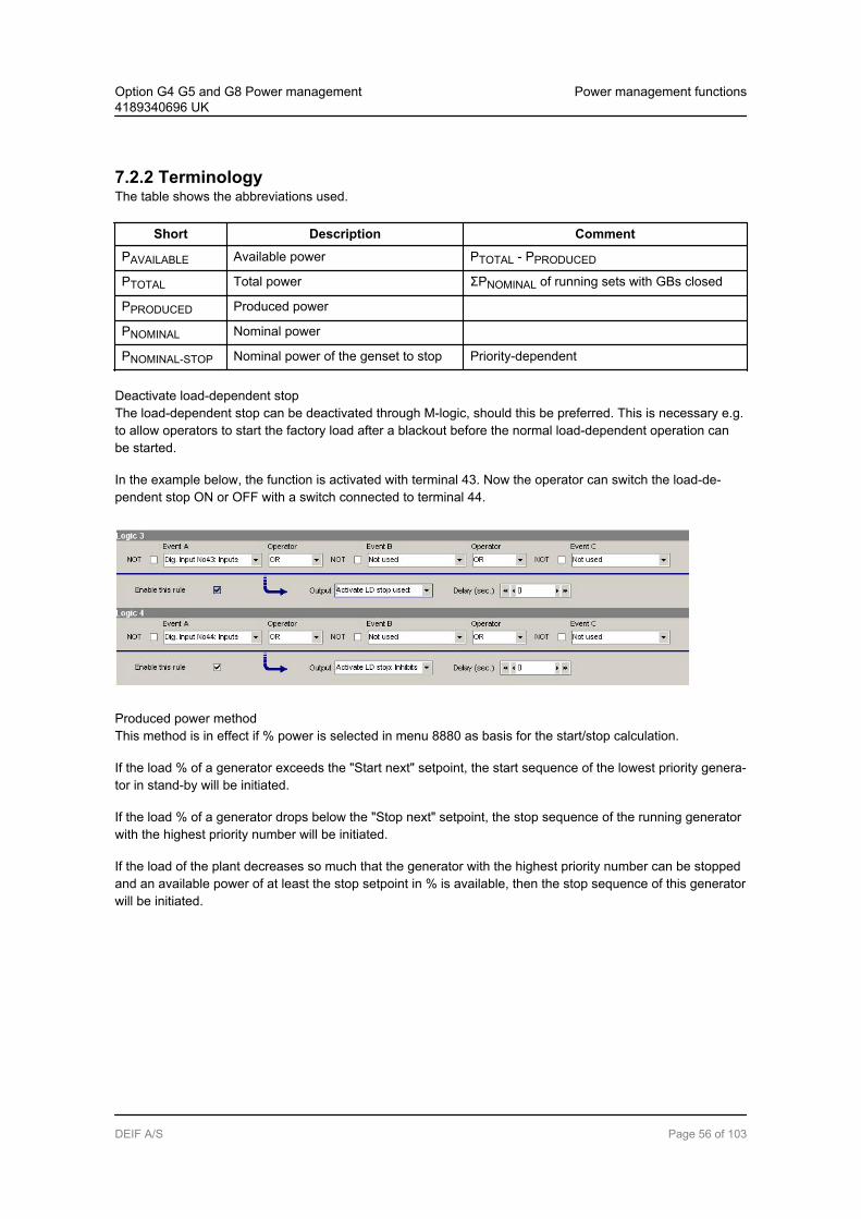
7.2.2 TerminologyThe table shows the abbreviations used.
Short Description Comment
PAVAILABLE Available power PTOTAL - PPRODUCED
PTOTAL Total power ΣPNOMINAL of running sets with GBs closed
PPRODUCED Produced power
PNOMINAL Nominal power
PNOMINAL-STOP Nominal power of the genset to stop Priority-dependent
Deactivate load-dependent stopThe load-dependent stop can be deactivated through M-logic, should this be preferred. This is necessary e.g.to allow operators to start the factory load after a blackout before the normal load-dependent operation canbe started.
In the example below, the function is activated with terminal 43. Now the operator can switch the load-de-pendent stop ON or OFF with a switch connected to terminal 44.
Produced power methodThis method is in effect if % power is selected in menu 8880 as basis for the start/stop calculation.
If the load % of a generator exceeds the "Start next" setpoint, the start sequence of the lowest priority genera-tor in stand-by will be initiated.
If the load % of a generator drops below the "Stop next" setpoint, the stop sequence of the running generatorwith the highest priority number will be initiated.
If the load of the plant decreases so much that the generator with the highest priority number can be stoppedand an available power of at least the stop setpoint in % is available, then the stop sequence of this generatorwill be initiated.
Option G4 G5 and G8 Power management4189340696 UK
Power management functions
DEIF A/S Page 56 of 103

-200
-100
0
100
200
300
400
500
kW% load
Time
1 2 3
Load dep. start90
10Load dep. stop
1 Load increase
2 ”Load start delay” runs out; PMS start command
3 Stand by genset running and connecting to the busbar
Power produced% power
Available power methodThis method is in effect if P [kW] or S [kVA] is selected as basis for the start/stop calculation.
Independent of the selection (P [kW] or S [kVA]), the functionality is basically identical; therefore the exampleof the functionality below will be given for the load-dependent start function with selected rated power (P) val-ue.
The apparent power setpoint is typically selected if the connected load has an inductive character and thepower factor is below 0.7.
Option G4 G5 and G8 Power management4189340696 UK
Power management functions
DEIF A/S Page 57 of 103

DescriptionThis drawing illustrates the terms used.
PNOM
1500 kW
PNOM
1000 kW
PNOM
1000 kW100%
70%
DG1 DG2 DG3
Σ = 2450 kW
Σ = 1050 kW (available power)
Σ = 3500 kW ~ 100%
Consumed power at the busbar
Nominal powerThe nominal power is the rated power of the genset that can be read on the type plate of the generator.
Total powerThe total power is the summation of the rated nominal power of each individual genset. In the example abovethe plant consists of three DGs:
DG1 = 1500 kWDG2 = 1000 kWDG3 = 1000 kW
That is a total of 3500 kW
Produced powerThe produced power is defined as the existing load on the busbar. In the example above the produced poweris indicated as the hatched area, and the total of the three gensets = 2450 kW.
Available powerThe available power is the difference between the maximum possible power produced by the gensets and theactual produced power.
In the example above the plant consists of three gensets, in total 3500 kW. The load consumes 2450 kW intotal. Since the total load PTOTAL is 3500 kW, and the produced load PPRODUCED is 2450 kW, then the avail-able power PAVAILABLE is 1050 kW, meaning that the gensets can handle this load if it should be added tothe busbar.
Option G4 G5 and G8 Power management4189340696 UK
Power management functions
DEIF A/S Page 58 of 103
7.2.3 Principle – available power methodOne genset is running and is supplying the load. The load increases which means that the available power/apparent power decreases. At a certain time the load has increased so much that only a little amount of pow-er/apparent power is available, and the next priority genset will be started in order to increase the amount ofavailable power/apparent power.
When the load drops, the available power/apparent power will increase. When the available power/apparentpower has increased above the stop level plus the nominal power of the last priority genset, then the last pri-ority genset will be stopped. Please note that the nominal power of the genset to be stopped is added to theadjusted stop level. The reason is that otherwise the available power/apparent power would immediately dropbelow the start level again.
Example:If the adjusted stop level is 200 kW (PSTOP = 200 kW), and the genset with the last priority is 1000kW, it is necessary that the available power reaches 1200 kW, because the available power will bereduced with 1000 kW immediately after the last priority genset is stopped.
7.2.4 Principle – percentage methodOne genset is running and is supplying the load. The load increases which means that the % load increases.At a certain time the load has increased so much that the load % start will start up the next priority genset inorder to take some of the load.
When the load drops, the produced power will decrease. When the produced power has decreased below thestop level plus the nominal power of the last priority genset, then the last priority genset will be stopped.Please note that the nominal power of the genset to be stopped is added to the adjusted stop level. The rea-son is that otherwise the produced power would immediately drop below the start level again.
Example:If the adjusted stop level is 10% (100 kW produced power), and the genset with the last priority is1000 kW, the last priority generator will produce 20% (200 W) after stop. It is necessary that the startlevel is above this value, otherwise an ongoing starting and stopping will take place.
Option G4 G5 and G8 Power management4189340696 UK
Power management functions
DEIF A/S Page 59 of 103

7.2.5 Adjusting load-dependent startIn the example below the available power is 200 kW. When the load increases, the available power dropsbelow the start limit. The stand-by genset will start when the start timer runs out, and after the synchronisingthe available power increases (in this example to 500 kW).
-200
-100
0
100
200
300
400
500
P-Avail. on busbar
Time
1 2 3
Load start limit
1 Load increase
2 ”Load start delay” runs out; PMS start command
3 Stand by genset running and connecting to the busbar
Measured P-Avail.Predicted P-Avail.
Option G4 G5 and G8 Power management4189340696 UK
Power management functions
DEIF A/S Page 60 of 103

7.2.6 Adjusting load-dependent stopIn the example below the available power is 500 kW. When the load decreases, the available power increa-ses to 750 kW. The AGC now calculates what happens if the last priority genset is stopped. In the examplebelow the last priority genset is 400 kW which means that it can be stopped, because the available power willstill be above the stop level.
Now the difference between the stop level and the available power is 50 kW. This means that only if the gen-set, which now has the last priority, is 50 kW, it can be stopped!
700
600
400
500
300
200
100
0
Load decreases
”Load stop delay” runs out; PM stop command
Last priority genset stopped
Load stop limit
1
1
2
3
2 3
If the order of priority is changed, the following must be observed:
If the priority does not seem to change as expected, it is because the load-dependent stopfunction is not able to stop the lowest priority after having started the new first priority. Thatwould cause two DGs to be running at low load instead of one DG.
Option G4 G5 and G8 Power management4189340696 UK
Power management functions
DEIF A/S Page 61 of 103

7.2.7 Power windowThe difference between the programmed load-dependent start and stop limits forms the power hysteresis be-tween the start and stop. This is shown in the diagram below:
Available power
at the busbar
Load-depending start
Load-depending stop
Load stop
limit
Load start
limit
1. DG
Start
2. DG
Start
3. DG
Start
3. DG
Stop
2. DG
Stop
Power
window
PD
G1
PD
G2
PD
G3
PD
G3
PD
G2
7.3 Load management
7.3.1 Load managementThe function is used to activate a relay when a specific amount of power is available. The purpose of thisfunction is to be able to connect load groups when the gensets of the emergency power plant are running.
In each of the gensets, five levels can be adjusted (menus 8220-8260):
Available power 1 Available power 2 Available power 3 Available power 4 Available power 5
These setpoints can activate a relay when the specific amount of available power is reached. The relay out-put can be used for connecting load groups when sufficient power is available. The relays will activate whenthe available power is higher than the setpoint, but be aware that when the load groups are being connected,the available power will decrease and the relay(s) deactivate again if the available power is below the set-point. So it is necessary to make an external holding circuit.
The number of available relays is option-dependent.
Option G4 G5 and G8 Power management4189340696 UK
Power management functions
DEIF A/S Page 62 of 103

Regarding the inhibit function, please refer to the Designer’s Reference Handbook.
It is possible to adjust different levels of available power in all gensets. This gives the possibility to use sever-al load groups if this is necessary.
Example:In the example below, generator #1 is started followed by generator #2. The simplified diagram shows the twogensets and two load groups that are being connected by the available power relays R1 and R2 on AGC1.
G
Diesel generator set 1
G
Diesel generator set 2
Load
Group 1
Trip load group 1
R1
K1
K1Load
Group 2
Trip load group 2
R2
K2
K2
R1 R2
Multi-line 2 Multi-line 2
7.3.2 Functionality description (refer to the diagram below)The generator #1 is started, and the timer t1 starts running when the GB1 closes. When the t1 is expired, theselected relay activates (R1), and in the example a 200 kW load group is connected. Now the available powerfalls to 300 kW. After some time the generator #2 is started and its generator breaker is synchronised. Whenthe GB2 closes, the timer t2 runs. When the timer t2 expires, the selected relay activates (R2), and the sec-ond load group of 200 kW is connected. Now the available power falls to 600 kW.
Option G4 G5 and G8 Power management4189340696 UK
Power management functions
DEIF A/S Page 63 of 103
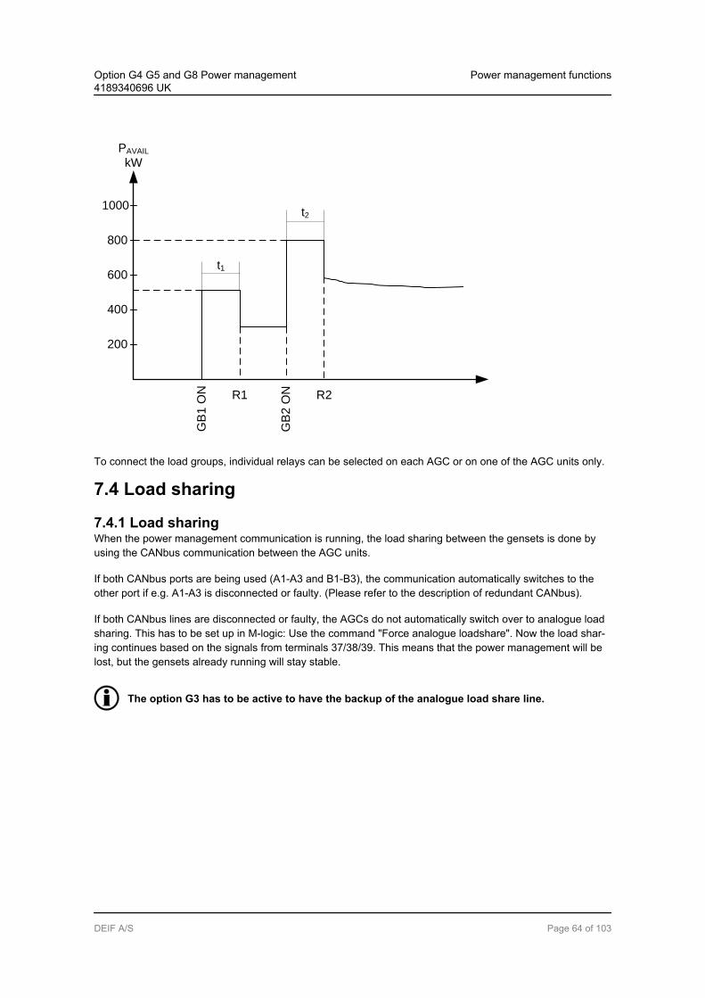
GB
1 O
N
t1
t2
R1 R2
200
1000
800
600
400
PAVAIL
kW
GB
2 O
N
To connect the load groups, individual relays can be selected on each AGC or on one of the AGC units only.
7.4 Load sharing
7.4.1 Load sharingWhen the power management communication is running, the load sharing between the gensets is done byusing the CANbus communication between the AGC units.
If both CANbus ports are being used (A1-A3 and B1-B3), the communication automatically switches to theother port if e.g. A1-A3 is disconnected or faulty. (Please refer to the description of redundant CANbus).
If both CANbus lines are disconnected or faulty, the AGCs do not automatically switch over to analogue loadsharing. This has to be set up in M-logic: Use the command "Force analogue loadshare". Now the load shar-ing continues based on the signals from terminals 37/38/39. This means that the power management will belost, but the gensets already running will stay stable.
The option G3 has to be active to have the backup of the analogue load share line.
Option G4 G5 and G8 Power management4189340696 UK
Power management functions
DEIF A/S Page 64 of 103
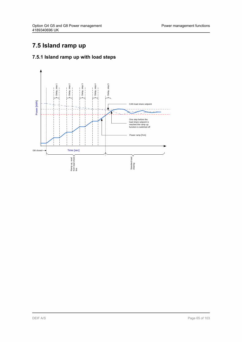
7.5 Island ramp up
7.5.1 Island ramp up with load steps
Po
we
r [k
Wh
]
Time [sec] GB closed
De
lay,
ste
p 1
Power ramp [%/s]
CAN load share setpoint
Ra
mp
up
, re
ad
fro
m lo
ad
sh
are
line Sta
nd
ard
lo
ad
sh
arin
g
One step before the
load share setpoint is
reached the ramp up
function is switched off
De
lay,
ste
p 2
De
lay,
ste
p 3
De
lay,
ste
p 4
De
lay,
ste
p 5
Option G4 G5 and G8 Power management4189340696 UK
Power management functions
DEIF A/S Page 65 of 103

7.6 Fixed power ramp up with load stepsP
ow
er
[kW
h]
Time [sec]GB closed
De
lay, ste
p 1
Power ramp
[%/s]
Power Set point
Ra
mp
do
wn
Stop signalR
am
p u
p, re
ad
Fro
m lo
ad
sh
are
line
De
lay, ste
p 2
De
lay, ste
p 3
De
lay, ste
p 4
De
lay, ste
p 5
When menu 2614 is enabled, the power setpoint continues to rise in ramp up steps, determined by menu2615, towards the load sharing setpoint. The delay time between each ramp up step will be determined bymenu 2613. The ramp up will continue until the load sharing setpoint is reached and then switch the regulatorto standard load sharing mode.
If the delay point is set to 20% and the number of load steps is set to 3, the genset will ramp to 20%, wait theconfigured delay time, ramp to 40%, wait, ramp to 60%, wait and then ramp to the system setpoint. If thesetpoint is at 50%, the ramp will stop at 50%.
7.7 Freeze power rampA way to define the ramp up steps is to use the freeze power ramp command in M-logic.
Freeze power ramp active:
1. The power ramp will stop at any point of the ramp, and this setpoint will be kept as long as the function isactive.
2. If the function is activated while ramping from one delay point to the other, the ramp will be fixed until thefunction is deactivated again.
3. If the function is activated while the delay timer is timing out, the timer will be stopped and will not contin-ue until the function is deactivated again.
Option G4 G5 and G8 Power management4189340696 UK
Power management functions
DEIF A/S Page 66 of 103

7.8 ATS applicationsTwo possibilities are available; the mains unit can either be installed or not.
7.8.1 AGC mains installed
See single line diagram for "Parallel with mains plant".
In an AMF application the AGC mains will normally operate the mains breaker and thereby make sure thatthe supply is coming from the mains if this is healthy.
This function allows the AGC to be used in an application where an automatic transfer switch is installed. Thisis known as an ATS.
In the applications shown as one-line diagrams in the chapter Functional description it can be seen that theATS will take care of the switching between the generator supply and the mains supply.
If ATS is selected, the AGC has no control over the ATS ("mains breaker").
DescriptionNormally the AGC detects a mains failure based on the voltage and frequency measurement on the mains.However, when ATS is selected in menu 7085 it is necessary to use a digital input together with the positionfeedbacks from the ATS. Thus, the mains failure is not detected by the AGC measurements but by the follow-ing two requirements:
1. Alternative start input ON2. ATS (MB) feedback OFF
To make the AGC detect a mains failure, the alternative start input has to be ON and the MB OFF feedbackhas to be active.
The input used as "Alternative start" function is configured in the PC utility software (USW).
The mains unit will not try to operate the ATS (mains breaker) at all. But it is still necessary that position feed-backs are wired up.
It is possible to have a tie breaker installed. This is useful if more gensets need to be started before supplyingthe load, because the tie breaker will not close until the required number of gensets is available.
7.8.2 ATS island mode
See single line diagram for "Island operating plant".
If this application is needed, the gensets can be started by activating the "auto start/stop" input. The gensetswill be started and stopped according to the power demand. That is, they will operate in load-dependent start/stop mode.
Option G4 G5 and G8 Power management4189340696 UK
Power management functions
DEIF A/S Page 67 of 103
Be aware that since no tie breaker is installed, it is important that the first genset to close onthe busbar can carry the load. If the load is too high, the genset will be overloaded.
This application can be combined with the multi start function.
7.9 Fail classThe fail classes described in the Designer’s Reference Handbook are still valid when the power managementoption is selected. In addition to these fail classes the safety stop can be used in the AGC units with powermanagement.
This means that when a trip + stop alarm occurs, the faulty genset will stay on the busbar until the next priori-ty genset is started and synchronised to the bus. When the incoming genset has taken the load, the faultygenset will ramp down the power, followed by trip of the breaker, cooling down of the engine and finally stop.
If the faulty genset has the last priority, or no standby gensets are available, then it will stay on the busbarand will not trip.
If no genset can start in a safety stop situation, then the faulty genset will not be stopped.Therefore it is important that the safety stop is backed up, e.g. by a trip and stop alarm or ashutdown alarm.
7.10 Local/remote operationThe plant can be adjusted to local, remote or timer operation (menu 8021). This selection is done in the com-mand unit, i.e. one of the generator units.
The setting defines how the plant is started while it is in AUTO mode.
The settings can be changed in M-logic and via display or PC utility software.
Display Utility SW(Parameter setup)
M-logic
Local X X X
Remote start X X X
The purpose of the selection is to decide whether the plant can be started from the display (local operator),from remote (e.g. PLC) or by an internal timer. Remote means that the control can be carried out by activat-ing the digital input or through Modbus/Profibus communication.
7.10.1 Local selectionAll operation is carried out on the display. In island operation any generator unit display can be used, and inload takeover, mains power export and fixed power the mains unit display must be used. The plant modemust be AUTO.
7.10.2 Remote selectionThe plant is started using the digital input "auto start/stop" when "remote" is selected.
Option G4 G5 and G8 Power management4189340696 UK
Power management functions
DEIF A/S Page 68 of 103

Island modeIn island mode the "auto start/stop" input on any of the generator AGCs can be used for starting the plant.However, DEIF recommends to wire up the "auto start/stop" input to all of the AGCs to be sure that the auto-matic operation is able to continue even though one of the DGs is taken out for service (power supply discon-nected to the AGC).
In island mode any running mode (MAN, AUTO, SEMI, BLOCK) can be selected on the generator units, andthe remote start signal is still working for the remaining AGC which is still in AUTO mode.
Parallel to mains modeIn load takeover, mains power export and fixed power mode the "auto start/stop" input on the mains unit mustbe used for starting the plant.
7.10.3 Plant operationThe table shows how the plant is started:
Plant mode Selection Local Remote
Island mode Display on generator units Auto start/stop on gen. units
Fixed power mode Display on mains unit Auto start/stop on mains unit
Mains power export Display on mains unit Auto start/stop on mains unit
Load takeover Display on mains unit Auto start/stop on mains unit
In peak shaving and AMF the automatic operation starts automatically depending on the impor-ted power (peak shaving) or mains failures (AMF).
Option G4 G5 and G8 Power management4189340696 UK
Power management functions
DEIF A/S Page 69 of 103
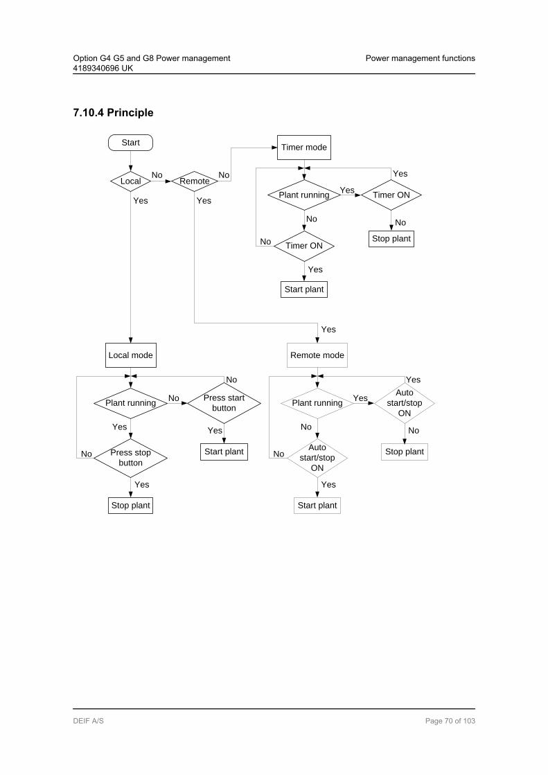
7.10.4 Principle
Start
LocalNo
RemoteNo
Press stop
button
Plant runningPress start
button
Yes
No
Yes
Yes
Local mode
Stop plant
No
No
Yes
Start plantAuto
start/stop
ON
Plant running
Auto
start/stop
ON
Yes
Yes
No
Yes
Remote mode
Start plant
No
Yes
No
Stop plant
Timer ON
Plant running Timer ONYes
No
Yes
Timer mode
Start plant
No
Yes
No
Stop plant
Yes
Option G4 G5 and G8 Power management4189340696 UK
Power management functions
DEIF A/S Page 70 of 103

7.11 Multi-starting gensetsThe multi-start function can be used to determine the number of gensets to start. This means that when thestart sequence is initiated through push-button, digital input or automatic start, then the adjusted numbers ofgensets will start.
This function is typically used e.g. together with applications where a certain number of gensets is required tosupply the load.
Example:In an AMF application with a tie breaker, the tie breaker must not close before the maximum power isavailable (power capacity setpoint).
The multi-start function is adjusted in menu 8922-8926.
7.11.1 Multi-start configurationThe multi-start function can be adjusted to operate with two different settings. These settings consist of set-points for how many gensets to start and the minimum number of running gensets.
It is possible to switch between the settings using M-Logic or menu 8924.
Setpoint 1 Setpoint 2
Multi-start (numbers to start) 8922 8925
Min no. running 8923 8926
Default setting
Start condition Setpoint 1 Setpoint 2 Default setting of DGs to start
Emergency operation Mains failure - X Start all DGs
Normal operation No mains failure X - Auto calculate
The default setting of the selection between setpoint 1 and setpoint 2 is made so the setpoint 1 is adjusted to"Auto calculation" and is used in all modes except for AMF. Setpoint 2 will automatically be selected in case amains failure occurs (this is adjusted in M-logic). Setpoint 2 is adjusted to 16 gensets which means that allavailable gensets will start when the mains failure occurs.
Option G4 G5 and G8 Power management4189340696 UK
Power management functions
DEIF A/S Page 71 of 103

The default setting can be changed, if convenient.
7.11.2 Numbers to startThe numbers to start (menu 8922/8925) can be selected depending on the number of DGs available. Theload-depending start and stop function will be active as soon as the generator breakers are closed or, if a tiebreaker is installed, as soon as the tie breaker is closed. It is possible to adjust the number of gensets, or anauto calculation can be selected.
If it is needed to delay the load-dependent start and stop function, it can be done through theM-logic function.
Auto calculationWhen auto calculation is selected, the sufficient number of gensets will be started as soon as the start com-mand is given. This is not depending on the plant mode.
Example:In a four DG plant each generator is rated with 1000 kW. The setpoint for load-dependent start (menu8001) is adjusted to 100 kW.
If a start command is given in fixed power mode and the setpoint is 2000 kW, then three gensets willbe started immediately and the fourth genset will remain stopped. Three gensets will be started be-cause two gensets are requested to supply the load (2*1000 = 2000 kW) and the load-dependent startfunction requests the third genset.
7.11.3 Minimum numbers runningThe multi starting function can be combined with the setting of a minimum number of running gensets (menu8923/8926). This means that the load-dependent stop function is disregarded when only the specific numberof gensets is running. This is also the situation even though the load would justify a load-dependent stop.
"Numbers to start" (menu 8922/8925) and "Minimum numbers running" (menu 8923/8926) areavailable for all modes.
Option G4 G5 and G8 Power management4189340696 UK
Power management functions
DEIF A/S Page 72 of 103

7.12 Priority selectionIt is possible to use one of five types of priority selection.
The parameter for each of the five priority selections will only be enabled (visible) when one ofthe five options is selected via the USW channel 8031, or by using the display parameter 8030Priority select.
7.12.1 ManualThe manual selection gives a possibility to adjust the order of priority between the adjusted numbers of avail-able DGs. This means that each genset always has a specific priority setting.
The adjustment is made in the menus 8080 (P1-P5), 8090 (P6-P11) and 8100 (P12-P16). In this example theorder of priority is DG3, DG1, DG2, DG4.
Priority/Genset DG1 DG2 DG3 DG4
Menu 8081 P1 X
Menu 8082 P2 X
Menu 8083 P3 X
Menu 8084 P4 X
These settings are only adjusted in the generator units. After the adjustment the order of priori-ty must be transmitted manually to the other gensets using the transmit function in menu 8086.
Manual abs. (absolute)Scenario:The four gensets in the drawing below are set up to have the same priority and ID (genset 1 has priority 1,etc.).
Option G4 G5 and G8 Power management4189340696 UK
Power management functions
DEIF A/S Page 73 of 103

When sections are separated with a BTB and the gensets are in AUTO, the “Manual abs” setup will at alltimes keep the priority adjusted for each controller. If the BTB is open the four gensets can start and stop astwo independent applications. E.g. if a genset is running on each side of the BTB, genset 1 and genset 3 willbe running as the first priority gensets. If the BTB is synchronised and closed the genset 2 will start and takeover the load from genset 3. When this is done, genset 3 is stopped and the application is now considered asone common application with four gensets.
Manual rel. (relative)Scenario:The four gensets in the drawing below are set up to have the same priority and ID (genset 1 has priority 1,etc.). “Manual relative” makes sense if there is a mains connection on each side of the BTB as shown in thepicture below.
When sections are separated with a BTB and the gensets are in AUTO, the “Manual rel” setup will auto-change the priority depending on the position of the BTB and depending on which mains ID has the “ID torun” function activated.
If the BTB is open the four gensets can start and stop as two independent applications. E.g. if the gensets 3and 4 are running on the right side of the BTB and the BTB is synchronised and closed, the gensets 1 and 2will not start and take over the load from gensets 3 and 4 as they are seen as new gensets being available inan already running application, and gensets 1 and 2 will now become priority 3 and 4.
Option G4 G5 and G8 Power management4189340696 UK
Power management functions
DEIF A/S Page 74 of 103

7.12.2 Running hoursThe purpose of the priority selection based on running hours is to let all the gensets have the same or nearlythe same amount of running hours.
Every time the adjusted period in menu 8111 is reached, a new order of priority is determined, and the gen-sets with first priorities will be started (if not already running), and the gensets with the last priorities will stop.
There are two possibilities for operating the priority routine based on the running hours: Absolute or relative.The selection between the absolute and relative routine defines whether the offset adjustment of the runninghours is taken into consideration in the priority calculation. The offset adjustment is used e.g. when the AGCis installed on an old genset which already has many running hours, or if an AGC is replaced.
Running hours abs. (absolute)All gensets participate in the priority routine based on the principle shown in the table below. This means thatthe gensets with the lowest number of running hours will be running. This can be a disadvantage for instanceif the application consists of old gensets together with new gensets. In that situation the new gensets will bethe first priorities, until they have reached the same number of running hours as the old gensets. To avoidthis, the priority routine called relative running hours can be used instead.
The actual number of running hours is adjusted in each genset AGC in menus 6101 and 6102, typically at thecommissioning. The purpose of the menu is to have the correct number of running hours displayed.
Option G4 G5 and G8 Power management4189340696 UK
Power management functions
DEIF A/S Page 75 of 103

Running hours rel. (relative)When "relative" is selected, all gensets will participate in the priority routine independently of the number ofrunning hours adjusted in menus 6101 and 6102. This means that all gensets in AUTO mode participate inthe priority routine. The relative selection gives a possibility to reset the priority routine. When the reset is acti-vated in menu 8113, the relative running hour counters in the AGC units will be reset to 0 hours, and at thenext priority selection the calculation is based on the reset values.
Principle for priority routineThe principle for the priority routine is described in the following table where the running hours (menu 8111)are adjusted to 24 hours. In this example only one genset is required by the load.
DG1(int. ID3)
DG2(int. ID2)
DG3(int. ID4)
DG4(int. ID1)
Comment
Monday 0 1051 h 1031 h 1031 h 1079 h DG2 will start due to the lowest internalID number
Tuesday 24 1051 h 1055 h 1031 h 1079 h DG3 will be started, and DG2 will bestopped
Wednesday 48 1051 h 1055 h 1055 h 1079 h DG1 will be started, and DG3 will bestopped
Thursday 72 1075 h 1055 h 1055 h 1079 h DG2 will be started due to the lowest in-ternal ID number, and DG1 will be stop-ped
Friday 96 1075 h 1079 h 1055 h 1079 h DG3 will be started, and DG 2 will bestopped
Saturday 120 1075 h 1079 h 1079 h 1079 h DG1 will be started, and DG3 will bestopped
Sunday 144 1099 h 1079 h 1079 h 1079 h DG4 will be started due to the lowest in-ternal ID number… and so on
The time adjusted in menu 8111 is the time between each priority calculation.
7.12.3 Fuel optimisationThe purpose of the fuel optimisation routine is to always let the gensets run in the best combination at anygiven load based on their actual nominal powers.
The settings are adjusted in the command unit.
The multi start function cannot be used together with the fuel optimising routine.
Option G4 G5 and G8 Power management4189340696 UK
Power management functions
DEIF A/S Page 76 of 103

DescriptionThe function is set up in the following menus:
Menunumber
Menu text Description Comment
8171 Setpoint Load with best fueleconomy (% ofPNOM)
The units will optimise around this genset load
8172 Swap set-point
Initiate optimising The improvement in nominal power must be betterthan this setpoint to initiate fuel optimising
8173 Delay Time delay Optimal combination must be present during this peri-od, before optimising is initiated
8174 Hour Running hours Maximum allowed difference in running hours
8175 Enable Activate runninghours
Activates the dependency of the running hours
The function is best described with an example. Below an example with three DGs is shown.
DG1 = 1000 kW DG2 = 1000 kW DG3 = 500 kW
Settings used in the fuel optimising function in this example:
8011 Load-dependent stop = 220 kW (extended with 10% in this function) 8171 Setpoint = 100% 8172 Swap percentage = 200 kW
Situation 1:The two 1000 kW gensets must operate. The load is too big for one 1000 kW and one 500 kW genset.
Situation 2:Since the load has decreased to 1400 kW, it would be enough with one 1000 kW and one 500 kW genset.The improvement is 500 kW which is better than 200 kW (menu 8172). The problem is that only 100 kWwould be available. The load-dependent stop requires 220 kW available, so no swapping can take place.
Situation 3:Now the load has decreased to 1300 kW. It would be enough with one 1000 kW and one 500 kW genset. Theimprovement is 500 kW which is better than 200 kW (menu 8172). The problem is that only 200 kW would beavailable. The load-dependent stop requires 220 kW available, so no swapping can take place.
Situation 4:Now the load has decreased to 1200 kW. It would be enough with one 1000 kW and one 500 kW genset. Theimprovement is 500 kW which is better than 200 kW (menu 8172). This means that 300 kW would be availa-ble, so the load-dependent stop does not interfere with the fuel optimising.
Fuel optimising is initiated!
Situation 5:Now DG3 has been started and is running with 400 kW. This is the best combination at this time, and noswapping takes place with this load.
Option G4 G5 and G8 Power management4189340696 UK
Power management functions
DEIF A/S Page 77 of 103
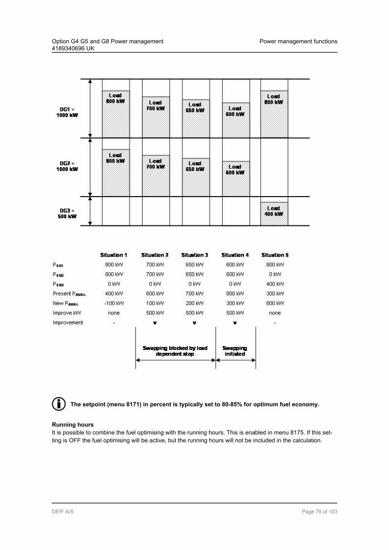
The setpoint (menu 8171) in percent is typically set to 80-85% for optimum fuel economy.
Running hoursIt is possible to combine the fuel optimising with the running hours. This is enabled in menu 8175. If this set-ting is OFF the fuel optimising will be active, but the running hours will not be included in the calculation.
Option G4 G5 and G8 Power management4189340696 UK
Power management functions
DEIF A/S Page 78 of 103

If the function "running hours" is enabled, the principle is the following: If one genset reaches the adjustedamount of running hours, it will be given quarantine. This means that it will just rest until it has the lowestnumber of running hours. The only exception to this is if there is no alternative combination. Then it will beused but will still be in quarantine.
7.13 Conditional connection of heavy consumersEach diesel generator unit is able to handle two heavy consumers (HC). When a heavy consumer is reques-ted, the function for conditional connection of heavy consumers reserves the programmed HC requested val-ue (parameter 8201/8211) on the busbar and blocks for engagement of the heavy consumer, until sufficientpredicted available power is present at the busbar.
Time
1 Request HC
2 Connect DG2
3 Acknowledge HC
-200
-100
0
100
200
300
400
500
kW
-250
-125
0
125
250
375
500
625
kVA
1
DG2 start
delayHC running
2 3 4 5
HC ackn
delay
DG2 stop
delay
700 kwAvailable power on busbar
Disable request HC
Disconnect DG2
4
5
HC request value: 375 kVA
HC nominal load: 150 kW
DG nominal power: 500 kW
Cos phi: 0.8
Load-dep. start value 90%
Load-dep. stop value 70%
HC request
value
Consumed power
Available power
When the available power is above the requested HC power, the heavy consumer is subsequently blockeduntil the programmed HC acknowledge delay runs out (fixed delay of 4 sec.).
The "DELAY ACK. HC" may be necessary in order to allow the recently started generator set to take load andthus actually increase the available power at the busbar before engagement of the HC.
The heavy consumers (HC) are connected according to their priority. This means that if two or more heavyconsumers request start acknowledgement at the same time, the HC with the highest priority is handled first,and subsequently HCs with lower priority, etc.
Option G4 G5 and G8 Power management4189340696 UK
Power management functions
DEIF A/S Page 79 of 103

HC 1.1 (1st HC in DG unit with CAN ID no. 1) is designated the highest priority. This means that HC 1.1 ishandled before HC 1.2, and HC 2.1 is handled before HC 2.2 if they are requested for start at the same time.If there are any preferential HCs, they must be connected to the hardware interface for the 1st HC in order toensure first priority handling.
The power management system carries out the following systematic sequence when a heavy consumer isrequested for start:
a) The programmed "HC n REQ. VALUE" is reserved at the busbar (parameter 8201/8211).b) A PMS start command is transmitted to the next stand-by generator set if the predicted available pow-
er is below the programmed "LOAD START LIMIT".c) When sufficient available power is present at the busbar, the timer "DELAY ACK. HC n" starts running
(fixed delay time of 4 sec.).d) The start acknowledge signal is transmitted to the HC in question when the timer "DELAY ACK. HC n"
runs out and sufficient available power is still measured at the busbar.e) The nominal HC power value (parameter 8202/8212) is used for load-dependent start/stop calculation
after the acknowledge signal is given.
7.13.1 Power feedback from the heavy consumerThe AGC is able to handle two types of power feedback:
Binary feedback Analogue feedback
The two types of power feedback signals are handled the same way by the conditional connection of heavyconsumers function.
Changing the power feedback type is done by a parameter (8203/8213) in each generator unit.
Activating the corresponding start request binary input activates the HC engagement sequence. The AGCsystem transmits a start acknowledge signal when sufficient predicted available power is present at the bus-bar.
Option G4 G5 and G8 Power management4189340696 UK
Power management functions
DEIF A/S Page 80 of 103

HC with binary power feedback signal:
188 kVA
150 kW
P-avail. OK
Time
0 kVA
Nom. power HC 1
300 kW
Power reservation
at the busbar
"Delay ACK. HC1"
Start acknowledge HC1
HC 1 fixed load
375 kVAStart request HC 1
Option G4 G5 and G8 Power management4189340696 UK
Power management functions
DEIF A/S Page 81 of 103

7.13.2 Engagement sequence for HCs with fixed loadThe power reservation by means of the feedback "HCx fixed load" input is enabled as long as the start re-quest signal is active. An OFF status (indicates that the HC is not operating) of the power feedback signalresults in a 100% power reservation at the busbar. An ON status (indicates that the HC is operating) at thepower feedback signal results in a 0% power reservation at the busbar.
HC with analogue power feedback signal:
P-avail.OK
Time
0 kVA
Nom. power HC 1
Request value 300 kW
Power reservation
at the busbar
25%
Start acknowledge HC1
HC 1 fixed load
4..20 mA
Start request HC 1
50%75%
100%
25%50%75%
100%
Nom.
power HC 1
The analogue power feedback for the heavy consumer is intended for a power transducer with a 4-20 mAoutput corresponding to 0-100% load. If the heavy consumer is of 400 kW, the power transducer has to becalibrated to 0-400 kW = 4-20 mA, and the setting has to be set for 400 kW.
7.14 Ground relay
7.14.1 Ground relayThe purpose of this function is to always let the star point of only one genset be connected to ground duringisland mode operation. The reason for this is to avoid circulating currents between the generators. The func-tion is adjusted in menu 8120.
If the gensets nominal power (Pnom) are equal, the AGC which has the first priority will activate its groundrelay when Hz/V is inside the acceptable range (menu 2111 + 2112). Should this genset stop when othergensets are connected, it will open its ground relay when the generator breaker opens. The ground relay ofthe generator which now has the next priority will close its ground relay instead. In case only one genset isconnected to the busbar and the breaker is tripped, it will keep the ground relay closed as long as the voltage/frequency is ok.
Option G4 G5 and G8 Power management4189340696 UK
Power management functions
DEIF A/S Page 82 of 103
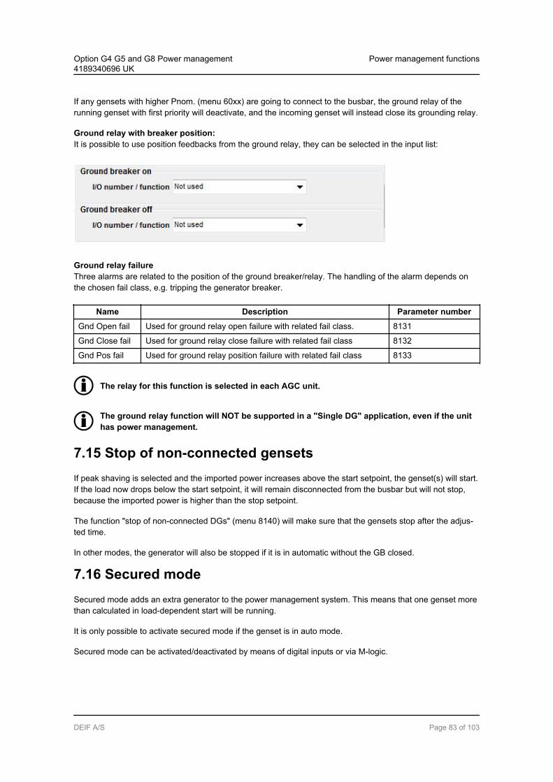
If any gensets with higher Pnom. (menu 60xx) are going to connect to the busbar, the ground relay of therunning genset with first priority will deactivate, and the incoming genset will instead close its grounding relay.
Ground relay with breaker position:It is possible to use position feedbacks from the ground relay, they can be selected in the input list:
Ground relay failureThree alarms are related to the position of the ground breaker/relay. The handling of the alarm depends onthe chosen fail class, e.g. tripping the generator breaker.
Name Description Parameter number
Gnd Open fail Used for ground relay open failure with related fail class. 8131
Gnd Close fail Used for ground relay close failure with related fail class 8132
Gnd Pos fail Used for ground relay position failure with related fail class 8133
The relay for this function is selected in each AGC unit.
The ground relay function will NOT be supported in a "Single DG" application, even if the unithas power management.
7.15 Stop of non-connected gensetsIf peak shaving is selected and the imported power increases above the start setpoint, the genset(s) will start.If the load now drops below the start setpoint, it will remain disconnected from the busbar but will not stop,because the imported power is higher than the stop setpoint.
The function "stop of non-connected DGs" (menu 8140) will make sure that the gensets stop after the adjus-ted time.
In other modes, the generator will also be stopped if it is in automatic without the GB closed.
7.16 Secured modeSecured mode adds an extra generator to the power management system. This means that one genset morethan calculated in load-dependent start will be running.
It is only possible to activate secured mode if the genset is in auto mode.
Secured mode can be activated/deactivated by means of digital inputs or via M-logic.
Option G4 G5 and G8 Power management4189340696 UK
Power management functions
DEIF A/S Page 83 of 103

The extra generator running in secured mode will be selected, so it is possible to replace thelargest running generator if this should fail.
7.17 Base loadOne genset unit in a power management system can be selected as running with base load (2952). This canbe done from the display unit, via M-logic or via a binary input. If the unit is selected to run with base load, thestatus message "FIXED POWER" will be indicated. The fixed power value can be adjusted with parameter2951.
If a generator runs in base load and the total load decreases to a point below the base load setpoint, the sys-tem will lower the fixed power setpoint. This is to prevent frequency control problems, as the generator run-ning in base load does not participate in the frequency control.
When the generator breaker is closed, the generator power will be increased to the fixed power setpoint.
If AVR control (option D1) is selected, the setpoint will be the adjusted power factor.
The unit selected for base load operation will automatically be set in SEMI-AUTO. Only onegenerator per independent busbar can run with base load.
The busbar has to be active with one or more DG units running, before the unit with the lowestID can activate base load.
Only one AGC unit at a time can run in base load. The unit with the lowest ID will be allowed torun in base load.
Option G4 G5 and G8 Power management4189340696 UK
Power management functions
DEIF A/S Page 84 of 103

7.18 Asymmetric load sharing (LS)When asymmetric LS is enabled in menu 8282, the "normal" G5 load sharing is deactivated in all AGC unitsin the system. The AGC units will then load share according to the asymmetric LS setpoint in menu 8281.
Example: Four DGs able to produce 2800 kW each as nominal power. Asymmetric LS setpoint = 90%. Loadon the busbar is 3030 kW.
The generator with priority 01 will start up first, taking 90% of the load = 2727 kW. The generator with priority02 will take the rest of the load = 303 kW.
DG 1 DG 2 DG 3 DG 4
303
90 %
2727
10 %
Total load on busbar = 3030 kW
kW
Loadshare
setpoint P01
Remaining
load P02
If the asymmetric LS setpoint in menu 8281 "kW value" is higher than the nominal power of thegenerators, the whole system will switch back to symmetric.
7.19 Tie breaker configuration
7.19.1 Tie breaker configurationSome of the possible applications of the AGC with option G5 can be used with a tie breaker, i.e. a breakerconnected between the gensets and the load bus.
7.19.2 Tie breaker selectionIn menu 8191, the tie breaker can be selected ON (present) or OFF (not present).
7.19.3 Tie breaker controlIt can be selected whether the tie breaker should be open or closed when the generators are stopped. Thisdepends on the application and the auxiliaries. If auxiliary load is connected to the generator bus, the tiebreaker must be closed, but if no load is connected to the generator bus, then the tie breaker is often prefer-red to be open when the generators are stopped.
The tie breaker will open or close depending on the setting in the menu 8191 ("Tie breaker enable").
Option G4 G5 and G8 Power management4189340696 UK
Power management functions
DEIF A/S Page 85 of 103

The tie breaker only opens or closes depending on the selection in menu 8191 and it is not de-pending on the selected mode whether it should open or close.
7.19.4 Tie breaker open pointIf the gensets are running parallel to mains and the mains breaker trips, e.g. due to a mains failure, it can benecessary to trip the tie breaker as well.
This depends on the total nominal power of the running gensets. If the gensets cannot supply the amount ofload which is adjusted in the "tie breaker open point" menu 8192, then the tie breaker will open. It will closeagain when the power capacity setpoint menu 8193 is reached.
This delay time can be used to trip non-essential load groups.
ExampleIn the example illustrated below it can be seen that the tie breaker will trip if DG1 or DG2 is connected to theload, because they are smaller than 510 kW. If DG1 and DG2 are running together, the tie breaker will alsotrip, because the total nominal power is still below 510 kW. If, however, DG3 is running alone or together withone of the two smaller DGs, then the tie breaker will not trip, because the total nominal power will be higherthan 510 kW.
DG 3 = 600 kW
DG 2 = 250 kW
DG 1 = 250 kW
Tie breaker open point = 510 kW
Trip No trip
The powers mentioned above are nominal powers of the gensets in the application.
It is possible to deload the tie breaker semi-auto mode with the M-Logic command "Act TB de-load"
7.19.5 Power capacityThe power capacity setting in menu 8193 is used in AMF applications to determine how much power must beavailable, before the tie breaker can close. When the gensets are started the generator breakers will close,and when sufficient power is available, then the tie breaker will be closed.
If there is more than one tie breaker in the power management system, it will close the one with the lowestpower capacity setting first.
Option G4 G5 and G8 Power management4189340696 UK
Power management functions
DEIF A/S Page 86 of 103
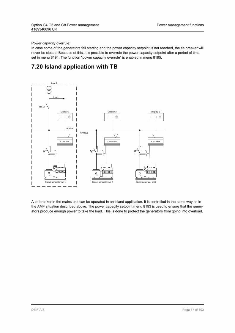
Power capacity overrule:In case some of the generators fail starting and the power capacity setpoint is not reached, the tie breaker willnever be closed. Because of this, it is possible to overrule the power capacity setpoint after a period of timeset in menu 8194. The function "power capacity overrule" is enabled in menu 8195.
7.20 Island application with TB
G
Diesel generator set 3
Controller
Display 3
G
Diesel generator set 1
Busbar
G
Diesel generator set 2
CANbus
Controller
Display 1
Controller
Display 2
Area 1
TB 17
Load
A tie breaker in the mains unit can be operated in an island application. It is controlled in the same way as inthe AMF situation described above. The power capacity setpoint menu 8193 is used to ensure that the gener-ators produce enough power to take the load. This is done to protect the generators from going into overload.
Option G4 G5 and G8 Power management4189340696 UK
Power management functions
DEIF A/S Page 87 of 103

7.21 Multiple mainsThe AGC can be used in an application with multiple mains incomers. This is an example of the multiplemains application:
CANbus
G
Diesel generator set 1
Controller
Display 1
TB 17
Load
MB 17
G
Diesel generator set 2
Busbar
Controller
Display 2
TB 18
Load
MB 18
G
Diesel generator set 5
Busbar
Controller
Display 5
TB 19
Load
MB 19
G
Diesel generator set 3
Controller
Display 3
Area 3
BTB 33
G
Diesel generator set 4
Controller
Display 4
BTB 34
Each application can handle:
0-16 mains feeders in the same application 0-16 gensets in the same application 8 bus tie breakers
The multiple mains functionality covers a great variety of different applications. Please contactDEIF support ([email protected]) for questions concerning the functionality.
Option G4 G5 and G8 Power management4189340696 UK
Power management functions
DEIF A/S Page 88 of 103

7.21.1 DefinitionsA multiple mains application consists of feeders and generators + a number of GBs, TBs, BTBs and MBs.
SectionsThe application consists of static and dynamic sections if one or more BTBs are installed. The definition of asection is mentioned in the table below.
Option G4 G5 and G8 Power management4189340696 UK
Power management functions
DEIF A/S Page 89 of 103

Section Definition
Static section Part of the total application which is separated by one or two open BTBs. There will be noclosed BTBs within this section.
A static section can also be a dynamic section, but not vice versa.
Dynamic sec-tion
Part of the total application which is separated by one or two open BTBs. There may beone or more closed BTBs within this section.
If no BTBs are installed, the application consists of a static section only.
Only use remote start signal in island application with BTB units.
CANbus
G
Diesel generator set 1
Busbar
Controller
Display 1
TB 17
Load
MB 17
G
Diesel generator set 3
Busbar
Controller
Display 3
TB 18
Load
MB 18
G
Diesel generator set 2
Controller
Display 2
Area 1
BTB 33 BTB 34
Static section:The BTB 33 is in open posi-tion. Therefore the indicatedsection is a static section.
Dynamic section:The section is separated by anopen BTB, so this is a dynamicsection.
Option G4 G5 and G8 Power management4189340696 UK
Power management functions
DEIF A/S Page 90 of 103

CANbus
G
Diesel generator set 1
Busbar
Controller
Display 1
TB 17
Load
MB 17
G
Diesel generator set 3
Busbar
Controller
Display 3
TB 18
Load
MB 18
G
Diesel generator set 2
Controller
Display 2
BTB 33 BTB 34
Area 1 Dynamic section:The BTB 34 is in closed posi-tion. Therefore the indicatedsection is a dynamic section.
7.21.2 ConfigurationPlease select "Standard" in the plant configuration tool to configure this application.
Now the application can be configured using the section control panel.
Option G4 G5 and G8 Power management4189340696 UK
Power management functions
DEIF A/S Page 91 of 103

7.21.3 Plant mode handlingBasically, six menus are available for setting up the functionality of the application.
No. Setting Min. setting Max. setting Factory setting
8181 MB failure start Enable OFF ON OFF
8182 Parallel Enable OFF ON OFF
8183 No break transfer Enable OFF ON OFF
8184 Auto switch Enable OFF Static Dynamic All OFF
8185 Run type Run one/all mains Run all mains Run one mains Run one mains
8186 Run type ID to run 17 32 17
MB close failure start:This setting determines whether a start of the DGs should be executed if an MB close failure occurs.
If "MB close failure start" is activated, the mode shift functionality will automatically be ena-bled.
Option G4 G5 and G8 Power management4189340696 UK
Power management functions
DEIF A/S Page 92 of 103

In peak shaving, fixed power, mains power export and load takeover, the function is only activewhen menu 7081 Mode shift is set to ON.
MB parallel:This setting determines whether the mains connections (MBs) should be able to run in parallel or not.
The setting of "MB parallel" affects the function of the "Auto switch" setting.
No break transfer:This setting determines whether switching between the mains connections (MBs) should be executed as ablack coupling or a synchronised coupling.
If the TBs in a section are adjusted to normally closed and "MB parallel" is switched OFF, then only one of theTBs can be closed at the time.
The system will try to keep the ID selected in menu 8186 ("My ID to Run") to keep its TB closed. If, however,the selected ID does not have a TB configured as a normally closed breaker, or if it fails to close it, it will bethe mains unit holding the lowest ID without TB failures present that will close.
If "My ID to Run" is changed during operation, then the MB parallel setting will decide whether a black or asynchronised change-over will take place.
If "MB parallel" is activated, the "No break transfer" will automatically be enabled.
Auto switch:This setting determines whether a mains unit detecting a mains failure will try to get the connected load sup-plied by another mains or by the available DGs.
Description Section de-scription
OFF The auto switch functionality is switched OFF.
Static section The back-up power is recovered within its own static section. Page 69
Dynamic sec-tion
The back-up power is recovered within its own dynamic section.The application will never try to synchronise/close a BTB to get help in anAMF situation.
Page 69
All sections The back-up power is recovered within all available sections.
Sections are divided by bus tie breakers. If no BTBs are installed, then the settings static/dy-namic/all have the same auto switch function.
If dynamic is selected, then please be aware that one mains unit will be requested to carry allload from the dynamic section without any help from the DGs.
Therefore the remaining mains feeders must be able to carry the load from the entire section.
Run type:This setting determines how the system in a dynamic section reacts in all the plant modes except island andAMF.
Option G4 G5 and G8 Power management4189340696 UK
Power management functions
DEIF A/S Page 93 of 103
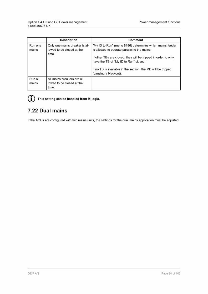
Description Comment
Run onemains
Only one mains breaker is al-lowed to be closed at thetime.
"My ID to Run" (menu 8186) determines which mains feederis allowed to operate parallel to the mains.
If other TBs are closed, they will be tripped in order to onlyhave the TB of "My ID to Run" closed.
If no TB is available in the section, the MB will be tripped(causing a blackout).
Run allmains
All mains breakers are al-lowed to be closed at thetime.
This setting can be handled from M-logic.
7.22 Dual mainsIf the AGCs are configured with two mains units, the settings for the dual mains application must be adjusted.
Option G4 G5 and G8 Power management4189340696 UK
Power management functions
DEIF A/S Page 94 of 103
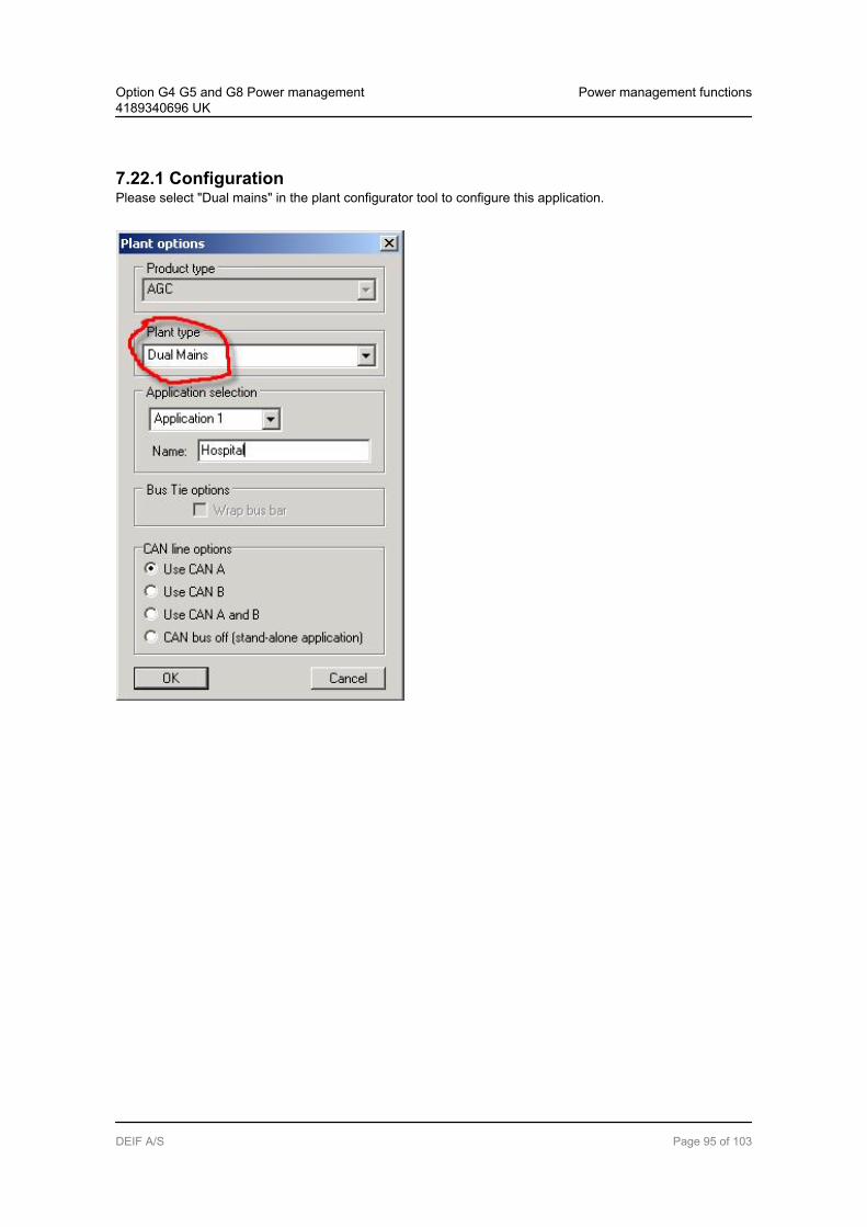
7.22.1 ConfigurationPlease select "Dual mains" in the plant configurator tool to configure this application.
Option G4 G5 and G8 Power management4189340696 UK
Power management functions
DEIF A/S Page 95 of 103
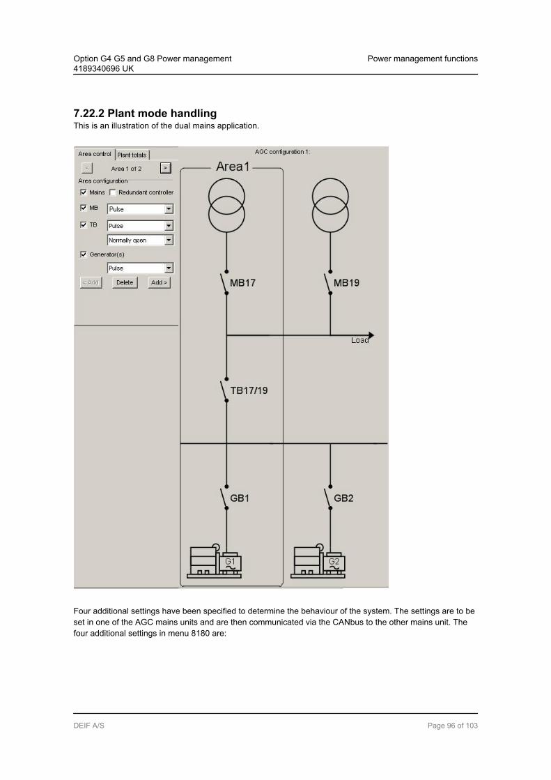
7.22.2 Plant mode handlingThis is an illustration of the dual mains application.
Four additional settings have been specified to determine the behaviour of the system. The settings are to beset in one of the AGC mains units and are then communicated via the CANbus to the other mains unit. Thefour additional settings in menu 8180 are:
Option G4 G5 and G8 Power management4189340696 UK
Power management functions
DEIF A/S Page 96 of 103
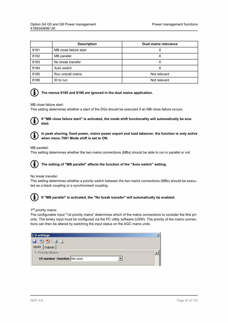
Description Dual mains relevance
8181 MB close failure start X
8182 MB parallel X
8183 No break transfer X
8184 Auto switch X
8185 Run one/all mains Not relevant
8186 ID to run Not relevant
The menus 8185 and 8186 are ignored in the dual mains application.
MB close failure start:This setting determines whether a start of the DGs should be executed if an MB close failure occurs.
If "MB close failure start" is activated, the mode shift functionality will automatically be ena-bled.
In peak shaving, fixed power, mains power export and load takeover, the function is only activewhen menu 7081 Mode shift is set to ON.
MB parallel:This setting determines whether the two mains connections (MBs) should be able to run in parallel or not.
The setting of "MB parallel" affects the function of the "Auto switch" setting.
No break transfer:This setting determines whether a priority switch between the two mains connections (MBs) should be execu-ted as a black coupling or a synchronised coupling.
If "MB parallel" is activated, the "No break transfer" will automatically be enabled.
1st priority mains:The configurable input "1st priority mains" determines which of the mains connections to consider the first pri-ority. The binary input must be configured via the PC utility software (USW). The priority of the mains connec-tions can then be altered by switching the input status on the AGC mains units.
Option G4 G5 and G8 Power management4189340696 UK
Power management functions
DEIF A/S Page 97 of 103

The "1st priority" input has to be active on one of the mains units at all times.
Auto switch:
MB parallel OFF:- If "Auto switch" is ON, an attempt will be made to switch to the 2nd priority mains if a mains failure
occurs on the 1st priority mains before the generators are started.- If "Auto switch" is OFF, no attempt will be made to switch to the 2nd priority in case of a mains
failure.
MB parallel ON:- If "Auto switch" is OFF, the two mains will act as one meaning that both mains breakers have to be
closed at all times, since one mains connection is not enough to supply the load. A mains failureon either of the mains will cause a trip of both mains breakers and subsequently start of the gen-sets.
- If "Auto switch" is ON, both mains breakers will be closed in case both mains are OK. If a mainsfailure occurs on one of the mains, the mains breaker in question will be tripped, but an AMF startof the gensets will only happen when a mains failure is present on both mains.
If "Auto switch" is enabled (ON), mode shift (menu 7081) must also be enabled (ON).
7.22.3 Internal CAN IDThe internal CAN ID for the AGC mains units can be set between 17 and 32 when multiple mains has beenselected (otherwise the system only expects one mains and the ID is set to 17 as default). The selection ofthe CAN ID cannot be made randomly but must be made with caution. The reason for this is that the systemexpects ID 17 and ID 18 as a couple controlling the mains breaker for one mains connection, i.e. the ID 18unit acts as a redundant unit to ID 17. In the same manner, the system expects ID 19 and ID 20 as a couplecontrolling the mains breaker for one mains connection, i.e. the ID 20 unit acts as a redundant unit to ID 19.This means that when no redundant mains units are present, the ID selected for the two AGC mains unitsmust be ID 17 and 19.
Setting of the CAN ID in multiple mains applications:
AGC mains unit ID no. Comment
1A 17 Required
1B 18 Not required, redundant to 1A
2A 19 Required
2B 20 Not required, redundant to 2A
Please refer to the drawing above for the location of the AGC mains units.
7.22.4 AGC mains unit redundancyIt is possible to install a redundant AGC mains unit for each mains connection. If this is done, the redundantAGC mains unit will automatically take control if:
Option G4 G5 and G8 Power management4189340696 UK
Power management functions
DEIF A/S Page 98 of 103
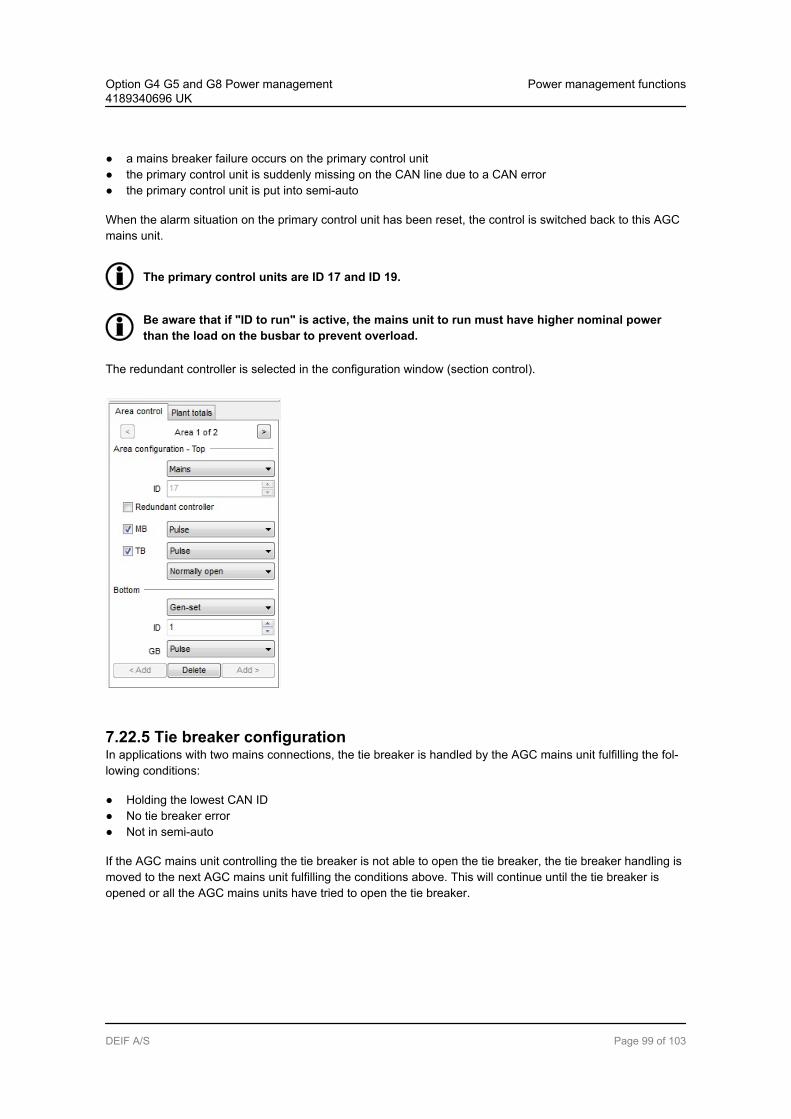
a mains breaker failure occurs on the primary control unit the primary control unit is suddenly missing on the CAN line due to a CAN error the primary control unit is put into semi-auto
When the alarm situation on the primary control unit has been reset, the control is switched back to this AGCmains unit.
The primary control units are ID 17 and ID 19.
Be aware that if "ID to run" is active, the mains unit to run must have higher nominal powerthan the load on the busbar to prevent overload.
The redundant controller is selected in the configuration window (section control).
7.22.5 Tie breaker configurationIn applications with two mains connections, the tie breaker is handled by the AGC mains unit fulfilling the fol-lowing conditions:
Holding the lowest CAN ID No tie breaker error Not in semi-auto
If the AGC mains unit controlling the tie breaker is not able to open the tie breaker, the tie breaker handling ismoved to the next AGC mains unit fulfilling the conditions above. This will continue until the tie breaker isopened or all the AGC mains units have tried to open the tie breaker.
Option G4 G5 and G8 Power management4189340696 UK
Power management functions
DEIF A/S Page 99 of 103

Because of the AC wiring it is not possible to synchronise the tie breaker in applications sup-porting two mains connections.
7.23 Configurable CAN IDs
Can IDs can be configured as desired, as a mix of DG, mains and BTB units:
16 gensets IDs 1-1616 mains IDs 17-328 bus tie breakers IDs 33-40
This makes a total of 40 CAN IDs.
Option G4 G5 and G8 Power management4189340696 UK
Power management functions
DEIF A/S Page 100 of 103
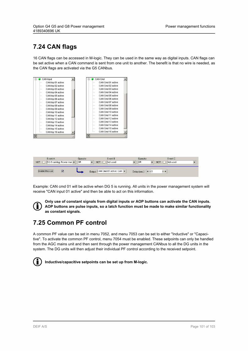
7.24 CAN flags16 CAN flags can be accessed in M-logic. They can be used in the same way as digital inputs. CAN flags canbe set active when a CAN command is sent from one unit to another. The benefit is that no wire is needed, asthe CAN flags are activated via the G5 CANbus.
Example: CAN cmd 01 will be active when DG 5 is running. All units in the power management system willreceive "CAN input 01 active" and then be able to act on this information.
Only use of constant signals from digital inputs or AOP buttons can activate the CAN inputs.AOP buttons are pulse inputs, so a latch function must be made to make similar functionalityas constant signals.
7.25 Common PF controlA common PF value can be set in menu 7052, and menu 7053 can be set to either "Inductive" or "Capaci-tive". To activate the common PF control, menu 7054 must be enabled. These setpoints can only be handledfrom the AGC mains unit and then sent through the power management CANbus to all the DG units in thesystem. The DG units will then adjust their individual PF control according to the received setpoint.
Inductive/capacitive setpoints can be set up from M-logic.
Option G4 G5 and G8 Power management4189340696 UK
Power management functions
DEIF A/S Page 101 of 103
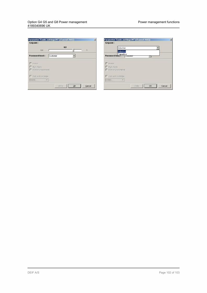
Option G4 G5 and G8 Power management4189340696 UK
Power management functions
DEIF A/S Page 102 of 103
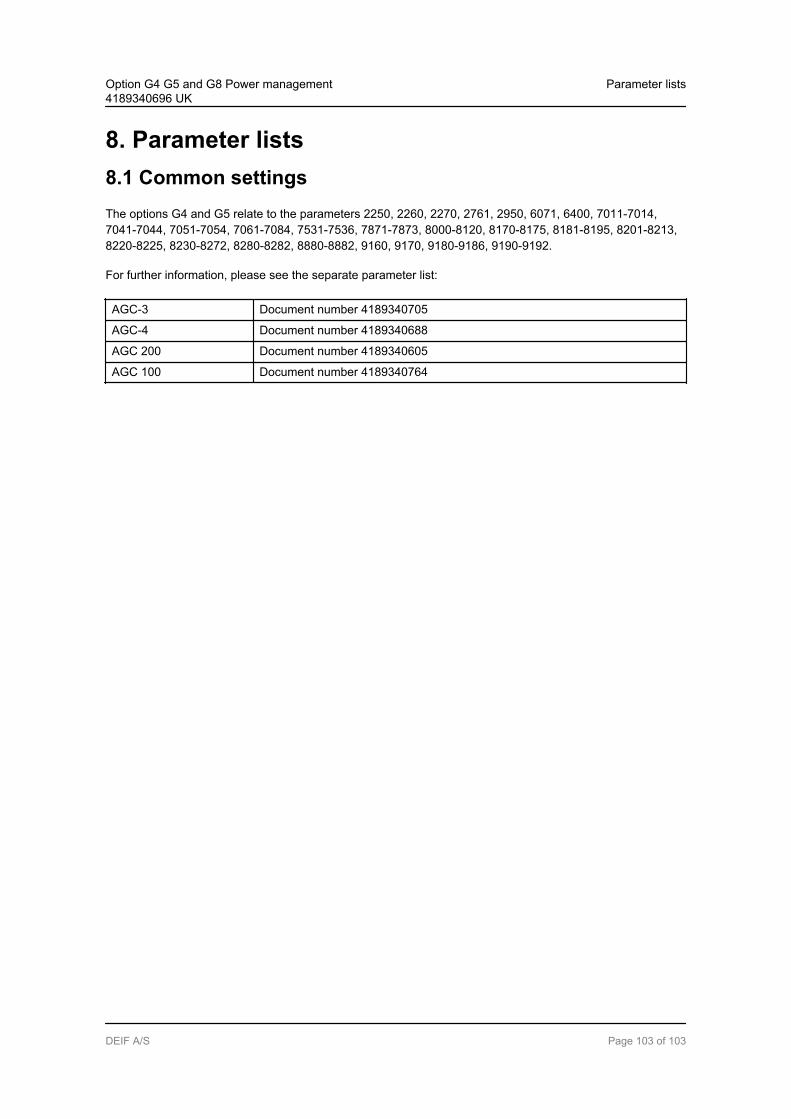
8. Parameter lists8.1 Common settingsThe options G4 and G5 relate to the parameters 2250, 2260, 2270, 2761, 2950, 6071, 6400, 7011-7014,7041-7044, 7051-7054, 7061-7084, 7531-7536, 7871-7873, 8000-8120, 8170-8175, 8181-8195, 8201-8213,8220-8225, 8230-8272, 8280-8282, 8880-8882, 9160, 9170, 9180-9186, 9190-9192.
For further information, please see the separate parameter list:
AGC-3 Document number 4189340705
AGC-4 Document number 4189340688
AGC 200 Document number 4189340605
AGC 100 Document number 4189340764
Option G4 G5 and G8 Power management4189340696 UK
Parameter lists
DEIF A/S Page 103 of 103


![L3 EEAF S5 2019#01.xlsx [Groupe] · 2019-10-06 · 30-sept 40 2h g1 g2 lundi g3 30-sept g4 g5 g6 g7 g8 2h g1 g2 mardi g3 01-oct g4 g5 g6 g7 g8 2h g1 g2 mercredi g3 02-oct g4 g5 g6](https://img.dokumen.tips/doc/110x75/5e56f1ffdf7dc573ac2b72e9/l3-eeaf-s5-201901xlsx-groupe-2019-10-06-30-sept-40-2h-g1-g2-lundi-g3-30-sept.jpg)


![L3 EEAF S5 2019#01.xlsx [Groupe] · 2019-09-27 · 30-sept 40 2H G1 G2 LUNDI G3 30-sept G4 G5 G6 G7 G8 2H G1 G2 MARDI G3 01-oct G4 G5 G6 G7 G8 2H G1 G2 MERCREDI G3 02-oct G4 G5 G6](https://img.dokumen.tips/doc/110x75/5e56f286f00ee64576718399/l3-eeaf-s5-201901xlsx-groupe-2019-09-27-30-sept-40-2h-g1-g2-lundi-g3-30-sept.jpg)