Embed Size (px)
Citation preview

International Journal of Advances in Engineering & Technology, May 2012.
©IJAET ISSN: 2231-1963
591 Vol. 3, Issue 2, pp. 591-605
OPTIMUM THICKNESS OF THREE-LAYER SHRINK FITTED
COMPOUND CYLINDER FOR UNIFORM STRESS
DISTRIBUTION
Ayub A. Miraje 1 and Sunil A. Patil
2
1Dept. of Mech. Eng, MIT College of Engineering, Pune, INDIA
2Dept. of Mech. Eng, Sinhgad Institute of Technology & Science, Pune, INDIA
ABSTRACT
This paper introduces the optimum design for minimization of thickness of three-layer shrink-fitted compound
cylinder to get equal maximum hoop stresses in all the cylinders. In the shrink-fitting problems, considering
long hollow cylinders, the plane strain hypothesis can be regarded as more natural. Generally, hoop stress
distribution across the wall of thick cylinder is non-linear in nature from inner to outer radius of the cylinder.
The stresses reduce sharply towards the outer radius. Material is not utilized properly giving unnecessary more
thickness. Hence two or more cylinders can be compounded by shrinkage process where outer cylinder is heated
until it will slide freely over inner cylinder thus exerting the required contact pressure on cooling. As a result of
shrinking, stress redistribution occurs across the wall of the compound cylinder and reduces the hoop stress and
makes it more or less uniform over the thickness. In this paper effort is made to find optimum minimum
thicknesses of three cylinders so that material volume is reduced and hoop stress is equal in all the cylinders.
The analytical results of optimum design calculated with computer programming are validated in comparison
with Finite Element Analysis in ANSYS Workbench. Both the results agree with each other. Hence this
methodology can be applied for real-world mechanical applications of multi-layer compound cylinders.
KEYWORDS: Residual Stress, Contact (Shrinkage) Pressure, Multi-layer Cylinder, Optimum Thickness
I. INTRODUCTION
Multilayer compound cylinders are widely used in the field of high pressure technology such as
hydraulic presses, forging presses, power plants, gas storages, chemical and nuclear plants, military
applications etc. To enhance load bearing capacity and life of multilayer pressure vessels, different
processes such as shrink fit and autofrettage are usually employed. Shrink fit increases load capacity.
Many researchers have focused on methods to extend lifetimes of vessels. Majzoobi et al. have
proposed the optimization of bi-metal compound cylinders and minimized the weight of compound
cylinder for a specific pressure [1]. The variables were shrinkage radius and shrinkage tolerance. Patil
S. A. has introduced optimum design of two layer compound cylinder and optimized intermediate,
outer diameter and shrinkage tolerance to get minimum volume of two layer compound cylinders [2-
3]. Hamid Jahed et al. have investigated the optimum design of a three-layered vessel for maximum
fatigue life expectancy under the combined effects of autofrettage and shrink fit [4]. Miraje Ayub A.
and Patil Sunil A. have found minimum volume of three-layer open type compound cylinder
considering plane stress hypothesis [5]. Yang Qiu-Ming et al. have presented a simple and visual tool
to calculate the residual stress and describe the distribution of residual stress for both the elastic-
perfectly plastic model and the strain-hardening mode [6].
To increase the pressure capacity of thick-walled cylinders, two or more cylinders (multi-layer) are
shrunk into each other with different diametric differences to form compound cylinder. In three-layer
compound cylinder the usual practice is to shrink the outer cylinder 3 on to the intermediate cylinder 2
and then shrink the resulting compound cylinder on to the inner cylinder 1 as shown in figure 1.

International Journal of Advances in Engineering & Technology, May 2012.
©IJAET ISSN: 2231-1963
592 Vol. 3, Issue 2, pp. 591-605
Figure 1. Three Layer Compound Cylinder
When the outer cylinder contracts on cooling the inner cylinder is brought into a state of compression.
The outer cylinder will conversely be brought into a state of tension. If this compound cylinder is now
subjected to internal pressure the resultant hoop stresses will be the algebraic sum of those resulting
from internal pressure and those resulting from shrinkage, thus a much smaller total fluctuation of
hoop stress is obtained.
Designer usually face the problem of determining maximum hoop stress or maximum working stress
to which shrunk-fit cylinder is subjected, the magnitude of shrinkage pressure or any combination.
The design of shrunk-fit cylinders is much simplified if each cylinder is considered as a separate
cylinder subjected simultaneously to the shrinkage pressure and the working pressure. Manufacturing
and assembly process of such cylinders of real-world applications introduces some residual stresses.
These residual stresses can be summed up with hoop stress developed due to internal pressure to find
maximum hoop stress in all the cylinders.
The paper is organized as follows: We have explained Lame’s theory as applied to compound cylinder
in section 2.Optimum thickness methodology for compound cylinder and analytical results in section
3. Validation using FEM and ANSYS results in section 4. Discussion in section 5 followed by
Conclusion in section 6.
II. LAME’S THEORY APPLIED TO COMPOUND CYLINDER
a) Cylinder 1 b) Cylinder 2 c) Cylinder 3
Figure 2. Radial and hoop stress distribution in three separate cylinders

International Journal of Advances in Engineering & Technology, May 2012.
©IJAET ISSN: 2231-1963
593 Vol. 3, Issue 2, pp. 591-605
Figure 3. Interference between cylinder 1 & 2 Figure 4. Interference between cylinder 2 & 3
Nomenclature
i
P Internal pressure acting on the cylinder 1
oP External pressure on the cylinder 3
σ θ Hoop stress in the cylinder
rσ Radial stress in the cylinder
zσ Longitudinal (Axial) stress in the cylinder
1r Inner radius of cylinder 1
2r Outer radius of cylinder 1 and Inner radius of cylinder 2
3r Outer radius of cylinder 2 and Inner radius of cylinder 3
4r Outer radius of cylinder 3
12sP Contact pressure between cylinder 1 and 2
23sP Contact pressure between cylinder 2 and 3
1oθε Hoop strain in the outer wall of cylinder 1
1r oU Radial displacement at outer wall of cylinder 1
2iθε Hoop strain in the inner wall of cylinder 2
2r iU Radial displacement at inner wall of cylinder 2
12δ
Total interference at the contact between cylinder 1 and 2
2oθε Hoop strain in the outer wall of cylinder 2
2r oU Radial displacement at outer wall of cylinder 2
3iθε Hoop strain in the inner wall of cylinder 3
3r iU Radial displacement at inner wall of cylinder 3
23δ
Total interference at the contact between cylinder 2 and 3
ν Poisson’s ratio
1t 2r / 1r
2t 3r / 2r
3t 4r / 3r
Consider three cylinders have same material. The method of solution for compound cylinders
constructed from similar materials is to break the problem down into four separate effects:
i) shrinkage pressure 12sP only on the cylinder 1
ii) shrinkage pressure 12sP and 23s
P only on the cylinder 2
iii) shrinkage pressure 23sP only on the cylinder 3
iv) internal pressure i
P only on the complete cylinder
Thus for each condition the hoop and radial stresses at any radius can be evaluated.

International Journal of Advances in Engineering & Technology, May 2012.
©IJAET ISSN: 2231-1963
594 Vol. 3, Issue 2, pp. 591-605
2.1 Radial and Hoop Stress in Cylinder 1
If i
P = 0 i. e. no internal pressure, radial stress in cylinder 1 is given by using Lame’s equation
2 2
2 1
12 2 2 2
2 1
1r s
r rP
r r rσ
= − −
− (1)
rσ is maximum at outer radius
2r of cylinder 1 . Using equation (1)
( )212max sr at r
Pσ = − (2)
Hoop stress in cylinder 1 is given by using Lame’s equation 2 2
2 1
12 2 2 2
2 1
1s
r rP
r r rθσ
= − +
− (3)
Hoop stress at outer radius 2
r is
( )2
2 2
2 1
12 2 2
2 1–
sat r
r rP
r rθ
σ +
= −
(4)
While hoop stress at inner radius 1r is
( )1
2
12 2
max 2 2
2 1
2s
at r
P r
r rθ
σ
= − −
(5)
In the shrink-fitting problems, considering long hollow cylinders, the plane strain hypothesis (in
general, 0zσ ≠ ) can be regarded as more natural. Hence as per the relation
( )z r θσ ν σ σ= +
the expression for the hoop strain is given by
[ ] [ ]21 1 1( ) (1 )r z r r r
E E Eθ θ θ θ θ
νε σ νσ νσ σ νσ ν σ σ ν σ νσ
+ = − − = − − + = − − .
Using equations (2) and (4), assuming plane strain condition the hoop strain at the outer wall 2
r of
cylinder 1 is
[ ] ( ) ( )2 2
12 11 12 122 2
22 1
1(1 ) 1
1 r oo s sr
Ur rP P
rE E rrθ θ
ν νε ν σ νσ ν
++− − − ν − =
− −
+= −
=
(6)
Radial displacement 1r o
U is
( )( )
2 212 2 2 1
1 2 2
2 1
11
s
r o
P r r rU
E r r
νν
− + += − − ν
−
(7)
2.2 Radial and Hoop Stress in Cylinder 2
Contact pressure 12s
P is acting as internal pressure and contact pressure 23s
P is acting as external
pressure on cylinder 2.
Using Lame’s equation, radial stress in the cylinder 2 at inner radius 2r is given by
( )212 sr at r
Pσ = − (8)
While radial stress in the cylinder 2 at outer radius 3
r is given by
( )323 sr at r
Pσ = − (9)
Hoop stress in the cylinder 2 at inner radius 2r is given by
( )2
2 2 2
12 3 2 23 3
max 2 2 2 2
3 2 3 2
( ) 2 ( )s s
at r
P r r P r
r r r rθ
σ+
= −− −
(10)
While hoop stress in the cylinder 2 at outer radius 3r is given by
( )3
2 2 2
12 2 23 3 2
2 2 2 2
3 2 3 2
2 ( ) ( )s s
at r
P r P r r
r r r rθ
σ+
= −− −
(11)
Using equations (8) and (10), assuming plane strain condition the hoop strain at the inner wall 2r of
cylinder 2 is

International Journal of Advances in Engineering & Technology, May 2012.
©IJAET ISSN: 2231-1963
595 Vol. 3, Issue 2, pp. 591-605
[ ] ( ) ( )2 2 2
3 2 23 3 22 12 122 2 2 2
23 2 3 2
1(1
211) sr
s r ii s
r r P r UP P
E rr r r rEθθ
ν νν σ σ νε ν
+ ++− − − ν − =
− − −
= − = (12)
Radial displacement 2r iU
( )( ) ( )
2 2 22 3 2 23 3
2 12 2 2 2 2
3 2 3 2
1 21 1 s
r i s
r r r P rU P
E r r r r
νν ν
+ +− + ν − −
− − =
(13)
Referring figure 3 and using equations (7) and (13), total interference 12δ at the contact between
cylinder 1 and 2 is
12 2 1r i r oU Uδ −=
( )
( ) ( )( )
( )2 2 2 2 2
2 12 23 2 23 3 2 1
12 2 2 2 2 2 2
3 2 3 2 2 1
1 121 1 1
ss
s
r P rr r P r r rP
E Er r r r r r
ν νν ν ν
+ − + + +− + ν − − − − − ν
− − − =
( ) 2 2 22 2
2 3 2 32 1
12 232 2 2 2 2 2
3 2 2 1 3
2
2
12
s s
r r r rr rP P
E r r r r r r
ν− + ++ −
− − −
=
(14)
Using equations (9) and (11), hoop strain in the outer wall 3r of cylinder 2 is given by
[ ] ( ) ( )2 2 2
12 2 23 3 2 22 232 2 2 2
33 2 3 2
1 2 ( ) (1(1
)) 1 s s r o
o r s
P r P r r UP
E rr r rE rθ θ
ν νν σ νε σ ν
++− − − ν − =
− −
+
= − − = (15)
Hence radial displacement 2r oU
( )
( ) ( )2 2 2
12 23 3 22 232 2 2 2
3 2 3 2
22 11 1
s
r o s
P rr r rU P
E r r r r
νν ν
− + − + − − ν
− −
= (16)
2.3 Radial and Hoop Stress in Cylinder 3
Contact pressure 23sP is acting as internal pressure on cylinder 3 and external pressure
oP
is zero.
Radial stress in the cylinder 3 at inner radius 3r is given by
( )323
sr at r
Pσ = − (17)
Hoop stress in the cylinder 3 at inner radius 3r is given by
3
2 2
23 4 3
( ) 2 2
4 3
( )s
max at r
P r r
r rθσ
+=
−
(18)
While hoop stress in the cylinder 3 at outer radius 4r is given by
4
2
23 3
( ) 2 2
4 3
2 ( )s
at r
P r
r rθσ =
− (19)
Using equations (17) and (18), hoop strain at inner wall 3r of cylinder 3 is given by
[ ] ( ) ( )2 2
23 4 3 33 232 2
34 3
( )11
1(1 ) s r i
i sr
P r r UP
E rr rEθθ
ν νν σ νε νσ
++− − ν − =
+= − −
− = (20)
Radial displacement 3r iU
( )( )
2 223 3 4 3
3 2 2
4 3
11
s
r i
P r r rU
E r r
νν
+ +− + ν
− = (21)
Referring figure 4 and using equations (16) and (21), total interference 23δ at the contact between
cylinder 2 and 3
3 2r i r oU U23 = −δ
( )( )
( )( ) ( )
22 2 2 212 223 3 4 3 3 3 2
232 2 2 2 2 2
4 3 2 2
2
3 3
2 111 1 1
ss
s
P rP r r r r r rP
E Er r r r r r
ννν ν ν
− + + + − + ν − − + − − ν
− − −
=

International Journal of Advances in Engineering & Technology, May 2012.
©IJAET ISSN: 2231-1963
596 Vol. 3, Issue 2, pp. 591-605
( ) 2 2 2 2 2
3 4 3 3 2 12 2
23 2 2 2 2 2 2
4 3 3 2 3
2
2
1 2s
s
r r r r r P rP
E r r r r r r
ν− + += + −
− − − (22)
Hoop stress at any radius r in compound cylinder due to internal pressure only is given by
2 2
1 4
2 2 2
4 1
1iPr r
r r rθσ
= +
− (23)
2.4 Principle of Superposition
After finding hoop stresses at all the radii, the principle of superposition is applied, i.e. the various
stresses are then combined algebraically to produce the resultant hoop stresses in the compound
cylinder subjected to both shrinkage pressures and internal pressurei
P .
2.4.1 Resultant hoop stress in Cylinder 1
a) Hoop stress due to i
P b) Residual stress due to 12s
P (c) Resultant stress 1θσ
Figure 5. Superposition of hoop stress due to i
P & residual stress due to12s
P in cylinder 1
Using equations (23) and (5), maximum hoop stress at the inner surfaces of cylinder 1 at 1r
2 2 2
4 1 2
1 122 2 2 2
4 1 2 1
2–
i s
r r rP P
r r r rθσ
+= −
− (24)
2.4.2 Resultant hoop stress in Cylinder 2
a) Hoop stress due to
iP b) Residual stress due to
12sP &
23sP (c) Resultant stress
2θσ
Figure 6. Superposition of hoop stress due to i
P & residual stress due to 12s
P &23s
P in cylinder 2
Using equations (23) and (10), maximum hoop stress at the inner surfaces of cylinder 2 at 2
r

International Journal of Advances in Engineering & Technology, May 2012.
©IJAET ISSN: 2231-1963
597 Vol. 3, Issue 2, pp. 591-605
2 2 2 22 2
1 12 3 2 23 34 2
2 2 2 2 2 2
2 4 1 3 2
( ) 2i s s
Pr P r r P rr r
r r r r rθσ
+ −+= +
− − (25)
2.4.3 Resultant hoop stress in Cylinder 3
a) Hoop stress due to
iP b) Residual stress due to
23sP (c) Resultant stress
3θσ
Figure 7. Superposition of hoop stress due to i
P & residual stress due to 23s
P in cylinder 3
Using equations (18) and (23), maximum hoop stress at the inner surfaces of cylinder 3 at 3
r
2 2 2 2 2
1 4 3 4 3
3 232 2 2 2 2
3 4 1 4 3
i
s
Pr r r r rP
r r r r rθσ
+ += +
− − (26)
2.4.4 Resultant hoop stress in Compound Cylinder
a) Hoop stress due to
iP b) Residual stress due to
12sP &
23sP (c) Resultant Hoop stress
Figure 8. Superposition of hoop stress due to i
P & residual stresses due to 12s
P &23s
P in all cylinders
III. METHODOLOGY OF OPTIMUM THICKNESS FOR COMPOUND CYLINDER
To obtain optimum values of the contact (shrinkage) pressures 12s
P and 23s
P which will produce equal
hoop (tensile) stresses in all the three cylinders, maximum hoop stresses given by the equations (24),
(25) and (26) have been equated.
Equating equations (24) and (25) i. e. 1 2θ θσ σ= and rearranging,
2 2 22 2 2 2 2 2
3 2 32 4 1 1 4 212 232 2 2 2 2 2 2 2 2 2 2
2 1 3 2 4 1 2 4 1 3 2
22
–s i s
r r rr r r r r rP P P
r r r r r r r r r r r
+ + ++ = − +
− − − −
(27)
Let the ratios 2 21
1 1
r dt
r d== , 3 3
2
2 2
r dt
r d== , 4
3
3 3
4r d
tr d
== (28)

International Journal of Advances in Engineering & Technology, May 2012.
©IJAET ISSN: 2231-1963
598 Vol. 3, Issue 2, pp. 591-605
Where 1 2 3 4, , ,d d d d are diameters corresponding to radii
1 2 3 4, , ,r r r r .
Hence 3 321 2
1 2 1
.r rr
t tr r r
== , 4 432 3
2 3 2
r r rt t
r r r== , 32
1 2 3
1 2 3
4 4
1
.rr r r
t t tr r r r
= =
Let 2 22 2 2
3 22 1 21 2 2 2 2 2 2
2 1 3 2 1 2
2 2 1
– –1 –1
r rr t tk
r r r r t t
+ ++ = +
−= (29)
2 2 2 2 22 2 2 2 2
1 2 3 2 34 1 1 4 22 2 2 2 2 2 2 2 2 2 2 2
4 1 2 4 1 1 2 3 1 2 3
1 1
1 1
t t t t tr r r r r
r r r r r t t t t t tk
+ ++ +− = −
− − − − = (30)
2 2
3 23 2 2 2
3 2 2
2 2
–1
r tk
r r t=
−= (31)
Hence equation (27) becomes
[ ] [ ]12 2 1 23 3 1/ /s i sP P k P k kk= + (32)
Equating equations (25) and (26) i. e. 2 3θ θσ σ= and rearranging,
2 2 2 2 2 2 2 22 2 2
3 2 1 4 3 4 3 31 4 2
12 232 2 2 2 2 2 2 2 2 2 2 2
3 2 3 4 1 2 4 1 4 3 3 2
( ) 2( )
– ( ) ( ) –s i s
r r r r r r r rr r rP P P
r r r r r r r r r r r r
+ + ++= − + +
− − −
(33)
Let 2 2 2
3 2 24 2 2 2
3 2 2
1
– –1
r r tk
r r t
+ += = (34)
2 2 2 2 2 22 2 2
1 4 3 3 2 31 4 25 2 2 2 2 2 2 2 2 2 2 2 2
3 4 1 2 4 1 1 2 3 1 2 3
( ) 1 1( )
( ) ( ) 1 1
r r r t t tr r rk
r r r r r r t t t t t t
+ + ++= − = −
− − − − (35)
2 2 2 2 2
4 3 3 3 26 2 2 2 2 2 2
4 3 3 2 3 2
2 1 2
– –1 –1
r r r t tk
r r r r t t
+ += + = +
− (36)
Hence equation (33) becomes
[ ] [ ]12 5 4 23 6 4 / /s i sP P k k P k k= + (37)
Equations (32) and (36) have been solved to get 12s
P and 23s
P in terms of i
P as follows,
( ) ( )( ) ( )
5 6 2 3
12
4 6 1 3
/ – /
/ – /s i
P Pk k k k
k k kk=
(38)
( ) ( )( ) ( )
5 4 2 1
23
3 1 6 4
/ – /
/ – /s i
k k
k
kP
k k
kP
k=
(39)
Putting the values of 1 2,t t and 3
t , the equations (14) and (22) can be written as
( ) 2 2 22 2 1 2
12 12 232 2 2
2
2
2 1
1 1 12
1 1 1s s
r t t tP P
E t t t
ν− + ++ −
− − −
δ =
(40)
( ) 2 2
3 3 122
23 23 2 2 2
3 2
2
2
1 1 21
1 1 1
s
s
r t PtP
E t t t
ν− + += + −
− − − δ
(41)
3.1 Analytical Method
For the given volume of fluid to be stored, the internal diameter of cylinder 1 ( 1d ) is known. Here it is
assumed as 100 mm. Material for all the three cylinders is assumed as same i. e. steel. Yield strength
of the steel material is y
σ = 250 MPa. Maximum hoop stress is major stress which is responsible for
failure of cylinder. Maximum principal stresses in all the cylinders (here it is maximum hoop stress)
should not exceed the yield stress of the material to avoid the failure of the compound cylinder.
Optimum material volume (assuming unit length) can be calculated using following steps.

International Journal of Advances in Engineering & Technology, May 2012.
©IJAET ISSN: 2231-1963
599 Vol. 3, Issue 2, pp. 591-605
1. Assume internal diameter of cylinder 1 ( 1d ) say 100 mm.
2. Select the ratios 2 21
1 1
r dt
r d== , 3 3
2
2 2
r dt
r d== , 4
3
3 3
4r d
tr d
==
3. For the given internal pressure iP , one can find contact (shrinkage) pressures 12s
P and 23sP in
terms of ratios 1t , 2
t and 3t .
4. Find the volume of the compound cylinder using 2 2
4 1.( ) / 4Fx d dπ= −
5. Minimize the volume subjected to the constraints,
i) 1 yθσ σ<= ii)
2 yθσ σ<= iii) 3 yθσ σ<= iv) 12
0δ > v) 230δ >
6. Optimized parameters 1t , 2
t , 3t are used for the design.
In computer programming, the values of 1t ,
2t and 3
t are selected from 1.1 to 2.4 with the increment
of 0.10, 0.05 and refined up to 0.002. Thus with lot of combinations of 1t ,
2t & 3
t material volume is
found. A number of combinations of 1t , 2
t and 3t satisfy the condition of equal maximum hoop
stresses in all three cylinders which is less than yield stress of the material. Out of these combinations
some important combinations are presented in this paper for comparison. However there is one unique
combination where volume is minimum. In programming, equations (38) and (39) are used to find
contact (shrinkage) pressures 12sP and 23s
P for given internal pressure iP resp. Also equations (40) and
(41) are used to find interferences 12 23,δ δ resp. These interferences are later used in section 4 for
modeling in Finite Element Method.
Algorithm of Computer Program
Assign values to 1d ,
yσ , E and i
P .
For ( 1t 1.10 to 2.4 with increment of 0.02)
For (2
t 1.10 to 2.4 with increment of 0.02)
For ( 3t 1.10 to 2.4 with increment of 0.02)
{
Calculate 1
k ,2
k ,3
k ,4
k ,5
k and6
k in terms of 1t ,
2t , 3
t .
Calculate 12s
P and 23s
P in terms of 1
k ,2
k ,3
k ,4
k ,5
k and6
k .
Calculate 12
δ and 23δ in terms of12s
P ,23s
P and1
k ,2
k ,3
k ,4
k ,5
k , 6k .
Calculate maximum hoop stresses 1θσ ,
2θσ ,3θσ in terms of i
P and 1t ,
2t , 3
t
Check the conditions1 yθσ σ<= ,
2 yθσ σ<= and 3 yθσ σ<=
Calculate the volume 2 2
4 1.( ) / 4Fx d dπ= −
Compare new calculated volume with previous one.
} // End of loops for 1t ,
2t and 3
t
Print the parameterized values and “Minimum Volume".
3.2 Analytical Results
Results from computer programming are listed in table 1 and 2.
Table 1. Diameters and ratios of diameters and Volume for compound cylinder (assuming 1d = 100 mm)
Combination 1t
2t
3t
2d 3d
4d
Fx
1 1.370 1.290 1.260 137.0 176.7 222.7 31090.30
2 1.285 1.305 1.325 128.5 167.7 222.2 30920.07
3 1.270
1.318
1.328
127.0
167.4
222.3
30953.17
Table 2. Maximum hoop stress, contact pressure and interference for compound cylinder
Combination 1θσ 2θσ
3θσ 12s
P 23s
P 12δ
23δ
1 249.94 249.94 249.94 29.5 19.6 0.038 0.032
2 250.00 250.00 250.00 25.0 20.6 0.027 0.030
International Journal of Advances in Engineering & Technology, May 2012.
©IJAET ISSN: 2231-1963
600 Vol. 3, Issue 2, pp. 591-605
3 250.00 250.00 250.00 24.1 20.6 0.026 0.031
The minimum volume of three-layer compound cylinder is 30920.07 mm3 corresponding to values in
combination 2 where ratios 1t = 1.285, 2
t = 1.305, 3t = 1.325. Hence optimum thickness of cylinder 1
is 28.5 mm, cylinder 2 is 39.2 mm and cylinder is 54.5 mm.
IV. VALIDATION USING FEM AND ANSYS RESULTS
Using optimized parameters 1t , 2
t , 3t from the combination set number 2 of the table 1 and taking 1d
= 100 mm remaining diameters 2 3 4, ,d d d are calculated as follows.
2d = 1
t x 1d
= 128.5mm, 3d
=
2t x 2d
= 167.7mm, 4d
= 3
t x 3d = 222.2mm.
The optimized values of 12 23,δ δ are radius based. These values are doubled to take diametric effect in
the three dimensional Finite Element Model. Using these values, inner diameter of cylinder 2 ( 2id )
and inner diameter of cylinder 3 ( 3id ) for shrink fit are calculated as shown in table 3.
Table 3. Data for modeling in ANSYS (for combination set number 2)
1t 2
t 3t 2d 2i
d 3d 3id 4d 12δ 23δ
1.285 1.305 1.325 128.500 128.446 167.700 167.640 222.20 0.027 0.030
where
1d , 2d = inner & outer diameters of cylinder 1 respectively.
2id , 3d = inner & outer diameters of cylinder 2 respectively for shrink fit.
3id , 4d = inner & outer diameters of cylinder 3 respectively for shrink fit.
Using the values of 12 23,δ δ shrink fit is applied between cylinders 1 & 2 and between cylinders 2 & 3
respectively in ANSYS Workbench. Contact between cylinders 1 & 2 as well as between cylinders 2
& 3 is applied using contact tool in ANSYS Workbench. Similarly, data for modeling is prepared for
combination set numbers 1 as well as 3 and modeling is done in ANSYS Workbench.
Figure 9. Three Layer Compound Cylinder Figure 10. Finite Element Mesh

International Journal of Advances in Engineering & Technology, May 2012.
©IJAET ISSN: 2231-1963
601 Vol. 3, Issue 2, pp. 591-605
Figure 11. Shrink fit between cylinder 1 & 2 Figure 12. Shrink fit between cylinder 2 & 3
Results by ANSYS Workbench for set number 1 are shown in the figures 13 to 17.
COMBINATION SET 1 ( 1t = 1.370, 2
t = 1.290, 3t = 1.260)
Figure 13. Maximum Principal Stress in cylinder 1
Figure 14. Maximum Principal Stress in cylinder 2 Figure 15. Maximum Principal Stress in cylinder 3
International Journal of Advances in Engineering & Technology, May 2012.
©IJAET ISSN: 2231-1963
602 Vol. 3, Issue 2, pp. 591-605
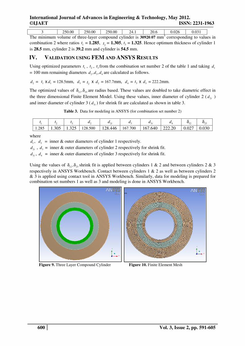
Figure 16. Contact pressure between cylinder 1 & 2 Figure 17. Contact pressure between cylinder 2 & 3
12sP
= 29.50 MPa (Avg) ( without Pi )
23sP = 20.01 MPa (Avg) ( without Pi )
Results by ANSYS Workbench for set number 2 are shown in the figures 18 to 22.
COMBINATION SET 2 ( 1
t = 1.285, 2t = 1.305, 3
t = 1.325)
Figure 18. Maximum Principal Stress in cylinder 1
Figure 19. Maximum Principal Stress in cylinder 2 Figure 20. Maximum Principal Stress in cylinder 3

International Journal of Advances in Engineering & Technology, May 2012.
©IJAET ISSN: 2231-1963
603 Vol. 3, Issue 2, pp. 591-605
Figure 21. Contact pressure between cylinder 1 & 2 Figure 22. Contact pressure between cylinder 2 & 3
12sP
= 22.58 MPa (Avg) (without Pi )
23sP = 19.00 MPa (Avg) ( without Pi )
Results by ANSYS Workbench for set number 3 are shown in the figures 23 to 27.
COMBINATION SET 3 ( 1t = 1.270, 2
t = 1.318, 3t = 1.328)
Figure 23. Maximum Principal Stress in cylinder 1
Figure 24. Maximum Principal Stress in cylinder 2 Figure 25. Maximum Principal Stress in cylinder 3
International Journal of Advances in Engineering & Technology, May 2012.
©IJAET ISSN: 2231-1963
604 Vol. 3, Issue 2, pp. 591-605
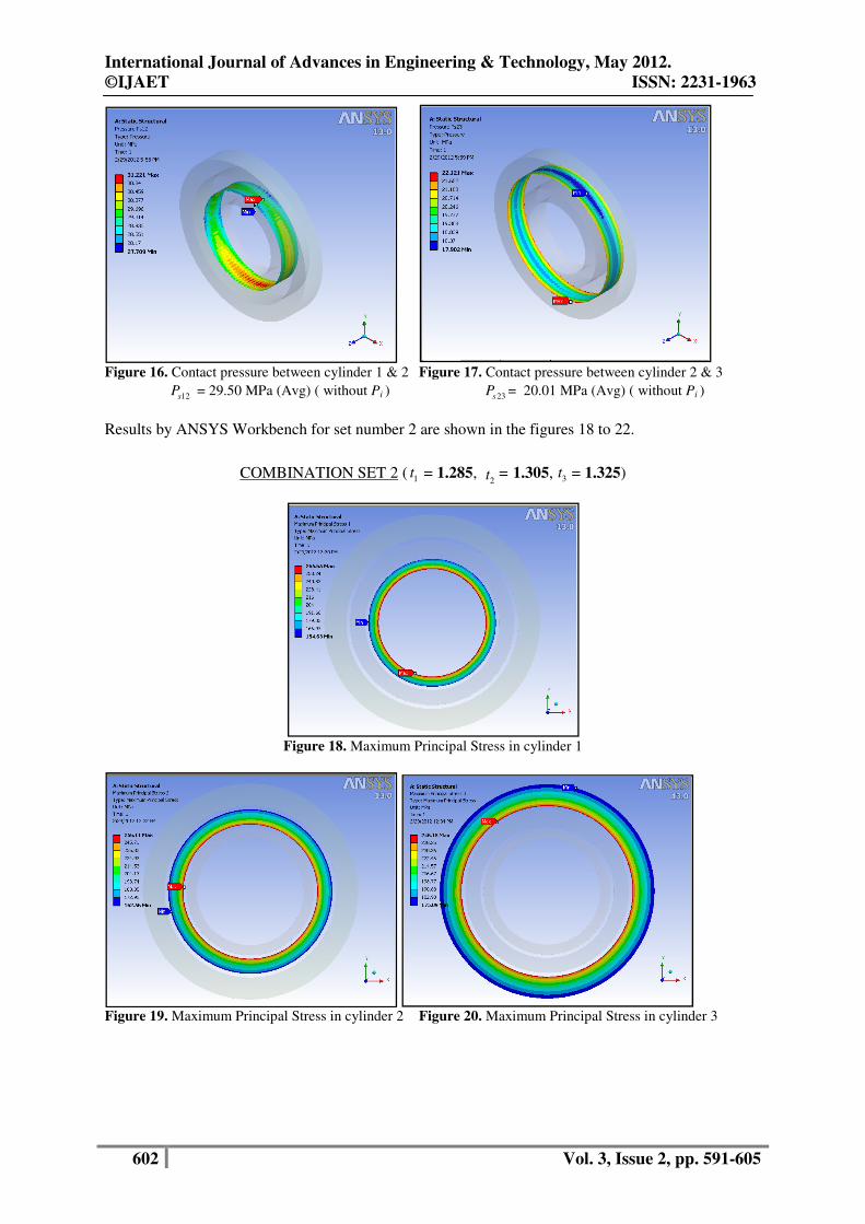
Figure 26. Contact pressure between cylinder 1 & 2 Figure 27. Contact pressure between cylinder 2 & 3
12sP
= 22.16 MPa (Avg) ( without Pi )
23sP = 19.03 MPa (Avg) ( without Pi )
V. DISCUSSION
Analytical results and FEM (ANSYS) results are summarized in Table 4 and 5.
Table 4. Comparison of hoop stresses by Analytical and ANSYS results
Combinations Results
Maximum hoop
stress in cylinder 1
1θσ ( MPa )
Maximum hoop stress
in cylinder 2 2θσ (
MPa )
Maximum hoop
stress in cylinder 3
3θσ (MPa )
1 Analytical 249.94 249.94 249.94
ANSYS 252.25 256.91 253.25
2 Analytical 250.00 250.00 250.00
ANSYS 265.65 256.11 246.15
3 Analytical 250.00 250.00 250.00
ANSYS 264.54 255.33 246.44
Table 5. Comparison of contact pressures by Analytical and ANSYS results
Combinations Results
Contact pressure between
cylinder 1 & 2
12sP ( MPa )
Contact pressure between
cylinder 2 & 3
23sP ( MPa )
1 Analytical 29.50 19.60
ANSYS 29.50 20.01
2 Analytical 25.00 20.60
ANSYS 22.58 19.00
3 Analytical 24.10 20.60
ANSYS 22.16 19.03
VI. CONCLUSION
From the tables 4 and 5 it is clear that the difference in analytical and ANSYS Software results is
within acceptable limits. This difference is due to numerical techniques of Finite Element Method in
ANSYS. Since analytical results are validated by FEM calculations, the design methodology proposed
in this paper can be successfully applied into the real-world mechanical applications for minimizing
the material volume of multi-layered compound cylinders to assure best utilization of material.
Patil S. A. [2-3] has found minimum volume of two layer compound cylinders as 37974.94 mm3 (for
internal diameter = 100 mm and steel material with yield strength = 250 MPa). Miraje Ayub A. and
Patil Sunil A. [5] have found minimum volume of three-layer open type compound cylinder as
31.778.98 mm3 considering plane stress hypothesis. In comparison with this, plane strain hypothesis
gave minimum volume as 30920.07 mm3 (as per combination set 2) which is quite significant to save
the material. Accordingly optimum thickness of cylinder 1 is 28.5 mm, optimum thickness of cylinder
International Journal of Advances in Engineering & Technology, May 2012.
©IJAET ISSN: 2231-1963
605 Vol. 3, Issue 2, pp. 591-605
2 is 39.2 mm and optimum thickness of cylinder is 54.5 mm. Hence it can be concluded that plane
strain hypothesis gives better results to find optimum thicknesses of long hollow compound cylinders.
ACKNOWLEDGEMENT The author is grateful to the Management, Executive Director, Principal, Head-Department of
Mechanical Engineering of MIT College of Engineering, Pune, India for time to time encouragement
and support in carrying out this research work.
REFERENCES [1] Majzoobi G.H. & Ghomi A., (2006) “Optimization of compound pressure cylinders”, Journal of
Achievements in Materials and Manufacturing Engineering, Vol. 15, Issue 1-2 March-April.
[2] Patil Sunil A., (2005) “Optimum Design of compound cylinder used for storing pressurized fluid”,
ASME International Mechanical Engineering Congress and Exposition (Proceeding of IMECE05),
Nov 5-11,2005,Orlando, Florida USA.
[3] Patil Sunil A., (2011) “Finite Element Analysis of optimized compound cylinder”, Journal of
Mechanical Engineering Research, Vol. 3(1), Issue March.
[4] Jahed Hamid, Farshi Behrooz & Karimi Morvarid, (2006) “Optimum Autofrettage & Shrink-Fit
Combination in Multi-Layer Cylinders”, Journal of Pressure Vessel Technology, Transactions of the
ASME, pp. 196-200 , Vol. 128, MAY 2006.
[5] Miraje Ayub A., Patil Sunil A.,(2011) “Minimization of material volume of three layer compound
cylinder having same materials subjected to internal pressure”, International Journal of Engineering,
Science and Technology , Vol. 3, No. 8, 2011, pp. 26-40.
[6] Yang Qiu-Ming, Lee Young-Shin, Lee Eun-Yup, Kim Jae-Hoon, Cha Ki-Up and Hong Suk-Kyun,
(2009) “A residual stress analysis program using a Matlab GUI on an autofrettaged compound
cylinder”, Journal of Mechanical Science and Technology , Vol. 23, pp. 2913-2920.
[7] Lee Eun-Yup, Lee Young-Shin, Yang Qui-Ming, Kim Jae-Hoon, Cha Ki-Up and Hong Suk-Kyun,
(2009) “Autofrettage process analysis of a compound cylinder based on the elastic-perfectly plastic and
strain hardening stress-strain curve”, Journal of Mechanical Science and Technology, 23 (2009), pp.
3153~3160.
[8] Park Jae-Hyun, Lee Young-Shin, Kim Jae-Hoon, Cha Ki-Up & Hong Suk-Kyun, (2008) “Machining
effect of the autofrettaged compound cylinder under varying overstrain levels”, Journal of Materials
Processing Technology , pp. 491–496.
[9] Torbacki W. (2007) “Numerical strength and fatigue analysis in application to hydraulic cylinders”,
Journal of Achievements in Materials and Manufacturing Engineering, Vol. 25 Issue 2, December
2007.
[10] Hojjati M.H. & Hassani A., (2007) “Theoretical and finite-element modeling of autofrettage process in
strain-hardening thick-walled cylinders”, International Journal of Pressure Vessels and Piping, 84
(2007) 310–319.
[11] Gibson Michael C. (2008) Determination of Residual Stress Distributions in Autofrettaged Thick-
Walled Cylinders, Ph. D. Thesis, Cranfield University, Defense College of Management and
Technology United Kingdom, April 2008. Biography
Ayub A. Miraje is a Assistant Professor in the Department of Mechanical Engineering at M I T
College of Engineering, Pune, India. He has 27 years of teaching experience and 1 year of
industrial experience. He has to his credit 10 papers in International and National Conferences. His
research interests include design optimization, finite element analysis, computer aided design and
manufacturing. He is a Life Member of ISTE (India).
Sunil A. Patil is a Professor in the Department of Mechanical Engineering at Sinhgad Institute of
Technology and Science, Pune, India. He has 10 years of industrial experience and 17 years of
teaching experience. He has to his credit 4 papers in International Conferences and 4 papers in
International Journals. His research interests include computer aided design and manufacturing,
Robotics, computational fluid dynamics, design optimization.