Embed Size (px)
Citation preview

Mining Science
Mining Science, vol. 25, 2018, 195–206 (Previously Prace NaukoweInstytutu Gornictwa PolitechnikiWroclawskiej, ISSN 0370-0798)
www.miningscience.pwr.edu.pl ISSN 2300-9586 (print)ISSN 2353-5423 (online)
Received June 21, 2018; reviewed; accepted September 28, 2018
OPTIMIZING SPLICE GEOMETRYIN MULTIPLY CONVEYOR BELTS|
WITH RESPECT TO STRESS IN ADHESIVE BONDS
Mirosław BAJDA*, Ryszard BŁAŻEJ,Monika HARDYGÓRAFaculty of Geoengineering, Mining and Geology, Wrocław University of Science and Technology, Poland
Abstract: This paper presents the results of investigations into stress distribution in the adhesive bonds ofmultiply conveyor belt splices. The splices were cold-vulcanized with the use of chemically hardeningglues having various strength parameters. The research results demonstrated that the length of splicesmay be reduced without the risk of lowering their tensile strength and fatigue life. The paper presentsstress values in adhesive joints of various belt types and the influence that the properties of belts, splicesand splicing materials have on stress values in the adhesive bond of the splice.
Keywords: belt conveyor, conveyor belt, textile belt splices, splice testing
1. INTRODUCTION
Increasing importance of belt conveyor transportation systems is accompanied byincreased expectations regarding their reliability. A need exists to design new, effi-cient and economically justified solutions for belt transportation. This goal may beachieved in the first place by lowering main motion resistances of the belt conveyor,i.e. lowering fictive friction coefficient f (Gładysiewicz et al. 2017). Greatest energyconsumption reductions may result from adequate idler selection (Król et al. 2017),from optimal spacing of load bearing idler sets (Gładysiewicz et al. 2016), and in
_________Corresponding author: [email protected] (M. Bajda)
doi.org/10.5277/msc182514
M. BAJDA et al.196
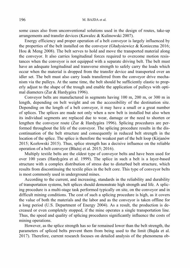
some cases also from unconventional solutions used in the design of routes, take-uparrangements and transfer devices (Kawalec & Kulinowski 2007).
Energy efficiency and proper operation of a belt conveyor is largely influenced bythe properties of the belt installed on the conveyor (Gładysiewicz & Konieczna 2016;Hou & Meng 2008). The belt serves to hold and move the transported material alongthe conveyor. It also carries longitudinal forces required to overcome motion resis-tances when the conveyor is not equipped with a separate driving belt. The belt musthave an adequate longitudinal and transverse strength to safely carry the loads whichoccur when the material is dropped from the transfer device and transported over anidler set. The belt must also carry loads transferred from the conveyor drive mecha-nism via the pulleys. At the same time, the belt should be sufficiently elastic to prop-erly adjust to the shape of the trough and enable the application of pulleys with opti-mal diameters (Żur & Hardygóra 1996).
Conveyor belts are manufactured in segments having 100 m, 200 m, or 300 m inlength, depending on belt weight and on the accessibility of the destination site.Depending on the length of a belt conveyor, it may have a small or a great numberof splices. The splices are made not only when a new belt is installed but also whenits individual segments are replaced due to wear, damage or the need to shorten orlengthen the conveyor route (Żur & Hardygóra 1996). Splicing procedures are per-formed throughout the life of the conveyor. The splicing procedure results in the dis-continuation of the belt structure and consequently in reduced belt strength in thelocation of the splice. The splice is therefore the weakest part of the belt loop (Kirjanów2015; Kozłowski 2015). Thus, splice strength has a decisive influence on the reliableoperation of a belt conveyor (Błażej et al. 2015; 2016).
Multiply textile belts are the oldest type of conveyor belts and have been used forover 100 years (Hardygóra et al. 1999). The splice in such a belt is a layer-basedstructure with a complex distribution of stress due to disturbed belt structure, whichresults from discontinuing the textile plies in the belt core. This type of conveyor beltsis most commonly used in underground mines.
According to the current, and increasing, standards in the reliability and durabilityof transportation systems, belt splices should demonstrate high strength and life. A splic-ing procedure is a multi-stage task performed typically on site, on the conveyor and indifficult mining conditions. The cost of such a splicing procedure is high, as it coversthe value of both the materials and the labor and as the conveyor is taken offline fora long period (U.S. Department of Energy 2004). As a result, the production is de-creased or even completely stopped, if the mine operates a single transportation line.Thus, the speed and quality of splicing procedures significantly influence the costs ofmining operations.
However, as the splice strength has so far remained lower than the belt strength, theparameters of spliced belts prevent them from being used to the limit (Bajda et al.2017). Therefore, current research focuses on detailed analysis of the phenomena ob-

Optimizing splice geometry in multiply conveyor belts with respect to stress in adhesive bonds 197
served in the splice region, as their better understanding will allow optimized splicegeometry and increased splice strength and durability (Project NCBiR 2015).
2. RESEARCH METHODOLOGY
Previous research into the strength of splices in textile belts served to determine the keyfactors influencing static tensile strength of splices (Komander et al. 2011). Practicaloperation of conveyor belts leads to an observation that their splices become delaminatedin the regions of their outer contacts. This phenomenon is a proof that due to fatigueloads the adhesive bond is more subject to damage than the covers. Increasing the fatiguelife of an adhesive bond is thus important for increasing splice durability. The above factmotivated research aimed at finding which properties of conveyor belts and their splicingmaterials have the most significant influence on stress levels in the adhesive bonds ofcold-vulcanized splices. The research methodology was developed as part of a researchproject carried out at Laboratorium Transportu Taśmowego (Belt Conveying Labora-tory), Wrocław University of Science and Technology (Project NCBiR 2015).
2.1. TESTS OF STRESSES IN ADHESIVE BONDS OF SPLICES
The object of tests consisted of three-step splices in four-ply textile belts, which weremade in accordance with the scheme shown in Fig. 1. The splicing technology is ofgreat significance to strength parameters of splices. The quality of such operations asstepping of the plies and removing their friction rubber, as well as vulcanization con-ditions, may result in defects which lower splice strength. Therefore, in order to elimi-nate the possibility of error, the surfaces of splices were meticulously prepared incontrolled conditions in an aboveground laboratory.
Belt ply number
Belt 1 Belt 2First splice step Second splice step Third splice step
Start of the first splice step
Contact between first and second splice step
End of the third splice stepContact between
second and third splice step
Fig. 1. Scheme of a three-step splice in a four-ply belt
M. BAJDA et al.198
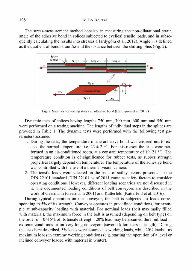
The stress-measurement method consists in measuring the non-dilatational strainangle of the adhesive bond in splices subjected to cyclical tensile loads, and in subse-quently calculating the results into stresses (Hardygóra et al. 2012). Angle γ is definedas the quotient of bond strain ΔS and the distance between the shifting plies (Fig. 2).
Splicecontact Step 1 Step 2 Step 3
Ply n
Ply n+1
Adhesive bond
Fig. 2. Samples for testing stress in adhesive bond (Hardygora et al. 2012)
Dynamic tests of splices having lengths 750 mm, 700 mm, 600 mm and 550 mmwere performed on a testing machine. The lengths of individual steps in the splices areprovided in Table 1. The dynamic tests were performed with the following test pa-rameters assumed:
1. During the tests, the temperature of the adhesive bond was ensured not to ex-ceed the normal temperature, i.e. 23 ± 2 °C. For this reason the tests were per-formed in an air-conditioned room, at a constant temperature of 19÷21 °C. Thetemperature condition is of significance for rubber tests, as rubber strengthproperties largely depend on temperature. The temperature of the adhesive bondwas controlled with the use of a thermal vision camera.
2. The tensile loads were selected on the basis of safety factors presented in theDIN 22101 standard. DIN 22101 as of 2011 contains safety factors to consideroperating conditions. However, different loading scenarios are not discussed init. The documented loading conditions of belt conveyors are described in thework of Geesmann (Geesmann 2001) and Katterfeld (Katterfeld et al. 2016).
During typical operation on the conveyor, the belt is subjected to loads corre-sponding to 5% of its strength. Conveyor operates in predefined conditions, for exam-ple at sub-capacity loading with material. For nominal loads (belt maximally filledwith material), the maximum force in the belt is assumed (depending on belt type) onthe order of 10÷15% of its tensile strength. 20% load may be assumed the limit load inextreme conditions or on very long conveyors (several kilometers in length). Duringthe tests here described, 5% loads were assumed as working loads, while 20% loads – asmaximum loads in extreme working conditions (e.g. starting the operation of a level orinclined conveyor loaded with material in winter).

Optimizing splice geometry in multiply conveyor belts with respect to stress in adhesive bonds 199
3. The frequency of splice tensioning was set at 0.3 Hz. At higher frequency thetemperature of the adhesive bond increases above 25 C.
The tests of strain in the adhesive bonds were performed on the splices of four-plybelts having nominal strengths of 800 and 1000 kN/m. The test were performed ac-cording to the following procedure: the splice sample (Fig. 2) made with chemicallyhardening glues was placed in the jaws of the testing machine cyclically (0.3 Hz)loaded with a force which effected stresses in the belt at between 5% and 20% of itsactual strength. After 3000 loading cycles, non-dilatational strain in the adhesive bondwas measured. In order to find the strain in the bond, the splice sample required properpreparation. For that purpose, the edge of the sample was carefully cleared, preparedand sprayed with a thin paint coating. A specially designed contour template was usedto mark vertical lines on the side of the sample. After 3000 loading cycles, the de-formed splice was photographed. Figure 4 shows a fragment of the splice sample withdeformations of the adhesive joint at the end of the third splice step, which is locatedbetween the third and the fourth ply. The damage visible in the bottom left part of thephotograph is the end of the splice (see Fig. 1). Defects in this location are typicallythe most extensive. The photographs were subsequently processed with the use of thecomputer and the results served to plot a graph of non-dilatational strain angle of theadhesive bond versus splice length. Each photograph of a vertical line was analyzedseparately. It was zoomed as required and processed in specialist software in order toread precise values of non-dilatational angle in the adhesive bond. Figure 3 showssample readings of the non-dilatational strain angle of the adhesive bond versus splicelength.
y = -0,58787336978228900x + 48,80841101903410000R² = 0,97931992737741500
y = 0,4836203919424850x - 82,6198982103566000R² = 0,9583557578191110
y = -0,65559031785831400x + 201,24543451818400000R² = 0,95475507909242100
y = 0,5634288851315630x - 239,2193106728390000R² = 0,9667152307470970
y = -0,5619224006826210x + 322,8412553168150000R² = 0,9804494839337380
y = 0,5203287159387670x - 339,1792227586460000R² = 0,9888135986001620
0
10
20
30
40
50
60
0 50 100 150 200 250 300 350 400 450 500 550 600 650 700 750
Non-
dila
tiona
l stra
in a
ngle
de
gree
s
Splice length, mm
Fig. 3. Non-dilatational strain angle of the adhesive bond in the EP 1000/4 belt (Project NCBiR, 2015)

M. BAJDA et al.200
The outer contacts of the splice showed significant bond strain exceeding 50.The deformations lower quickly towards the central part of the step, where a regionis observed in which angle γ = 0 (l0). Non-dilatational strain angles on the contactsof inner steps are smaller than on the contacts of outer steps, and the length of thezero-deformation zone l0 of the inner step is greater than in the case of the outersteps.
Fig. 4. Example of deformations in the adhesive bond of the splicelocated at the end of the third step, between ply 3 and 4
Further, the procedure consisted in calculating the values of angles γ into unitelongations of the adhesive bond. By calculating the angles into elongations and byallowing for the characteristic values of rubber adhesive tensioning, it was possible toplot graphs of stress distribution in the adhesive bond along the length of particularsplice steps. Their examples are provided in Fig. 5.
0
1
2
3
4
5
6
7
0 50 100 150 200 250 300 350 400 450 500 550 600 650 700 750
Shea
ring
stre
sses
, MPa
Splice length, mm
step 1 step 2 step 3
Fig. 5. Example of stress distributions in the adhesive bonds of a splice
The measurements included the values of non-dilatational strain angles γ in the ad-hesive bonds of various three-step splices 750 mm (3 250 mm) in length. The resultsindicate that with the splice loaded with a tensile load equal to 20% of belt strength,

Optimizing splice geometry in multiply conveyor belts with respect to stress in adhesive bonds 201
angles γ in the central fragments of adhesive bonds for each step are equal to zero.This fact means that these regions are not subjected to shear stresses. The length l0 ofthese fragments is a reserve indicating that the splice length may be reduced to someextent. This observation applies in particular to the inner step, as the stresses on itscontacts are lower than the stresses on the contacts of the outer steps.
2.2. TEST RESULTS
Test results of stresses acting on the contacts of splice steps having shortened geome-try are provided in Table 1. Splices marked 1÷4 are made of belt having actualstrength equal to 793 kN/m, while splices marked 4÷8 are made of belt having actualstrength equal to 1097 kN/m.
Apart from splices having a standard length of 750 mm (Nos. 1 and 5), Table 1 alsoincludes test results for splices having various step lengths:
splices 2 and 6 – inner step length reduced by 50 mm, outer step lengths un-changed, splice length equal to 700 mm,
splices 3 and 7 – all steps have lengths reduced by 50 mm, splice length equal to600 mm,
splices 4 and 8 – inner step lengths reduced by 50 mm, middle step length re-duced by 100 mm, splice length equal to 550 mm.
Table 1. Maximum stresses acting on the contacts of splice steps
Splice step lengthls, mmSplice
No.1 2 3
SplicelengthLp, mm
Lengthof the γ = 0 regions
in the splicel0, mm
Max. shearing stresson step contacts,max, N/mm2
1 250 250 250 750 373 7.32 250 200 250 700 343 7.73 200 200 200 600 301 8.44 200 150 200 550 291 9.25 250 250 250 750 390 7.26 250 200 250 700 366 7.77 200 200 200 600 299 8.28 200 150 200 550 279 9.1
The research project also included investigations into stresses in splices made withthe use of four-ply belts having actual strengths from 800 kN/m to 1600 kN/m. Thebelts for splicing, as well as the splices themselves, were tested in order to find theirbasic strength properties (Project NCBiR 2015).

M. BAJDA et al.202
3. TEST RESULTS ANALYSIS
The research demonstrated that the greatest values l0 occur in splices having lengthequal to 750 mm. Reducing the step length results in reduced lengths of segments l0and thus – reduced area of the regions which do not carry loads. At the same time,maximum stresses on step contacts increase. Figure 6 shows how these stresses in-crease in relation to shortening the splice.
y = 0,0029x2 ‐ 0,0059x + 7,294R² = 0,9981
y = 0,0031x2 ‐ 0,0125x + 7,2013R² = 0,9999
7
7,5
8
8,5
9
9,5
10
0 5 10 15 20 25 30Max. stress on step contacts
σ, N
/mm
2
Splice strength reduction, %
Wielob. (EP 800 splice)
Wielob. (EP1000 splice)
Fig. 6. Relationship between max. stresses on step contactsand the extent of step length reduction
The research into the relationship between individual splice step lengths andstresses in the adhesive bond demonstrated that shortening the inner step by 50 mmhad practically no influence on the stress values. Reducing the length of all steps by50 mm, and hence of the whole splice by 20%, effected an increase of stress by ap-prox. 14%. At the same time, segments l0 were shortened, leading to more effectiveusage of the steps.
The research into the relationship between individual splice step lengths and stressesin the adhesive bond demonstrated that shortening all steps by 50 mm had no influenceon the stress values. Although reducing the length of the inner step by 100 mm slightlyincreases stresses in the adhesive bond of the inner step, the stress values are still signifi-cantly lower than stresses in the outer steps, while step lengths are used more effectively.The influence of splice step length on the values and distributions of stress in adhe-sive bond are illustrated on the example of a splice made in belt EP-1000/4 andshown in Fig. 6.
The upper graph shows stresses in a typical splice having length 3 250 = 750 mm.The stress distributions are to a great extent non-uniform: high stresses are observedon the contacts of the outer steps and lower – on the contacts of the inner steps. At the

Optimizing splice geometry in multiply conveyor belts with respect to stress in adhesive bonds 203
same time large regions are observed not to take part in the load-carrying process. Themiddle graph shows the distribution of stresses in the adhesive bond of a splice inwhich the length of the inner step is reduced to 200 mm, and the bottom graphshows stresses distribution in a splice, in which the outer steps were shortened by50 mm and the inner step was shortened by 100 mm. The splice shortened by 200 mmin a 200 + 150 + 200 = 550 mm pattern has a more uniform stress distribution.Stresses on the outer contacts are slightly greater than stresses in a standard splice, andthe regions which do not carry loads are smaller.
0123456789
10
0 50 100 150 200 250 300 350 400 450 500 550 600 650 700 750
Shearing stresses, M
pa
Długość połączenia, mm
0123456789
10
0 50 100 150 200 250 300 350 400 450 500 550 600 650 700 750
Shearing stresses, M
pa
Długość połaczenia, mm
0123456789
10
0 50 100 150 200 250 300 350 400 450 500 550 600 650 700 750
Shearing stresses, M
Pa
Splice length, mm
Fig. 6. Stress distribution in the adhesive bond along the length of the complete splice:upper – 750 (3 250) mm, middle – 700 (250 200 250) mm, bottom – 600 (3 200) mm
According to PN-C-94147:1997 the lengths of individual steps in a splice are equaland depend on the strength of an individual ply (Table 2).
Based on the research results, a conclusion was made that the length of steps incold-vulcanized splices may be reduced and that the inner steps in a splice may beshorter than the outer steps without reducing splice strength or durability. The fatigue

M. BAJDA et al.204
tests of shortened splices did not indicate lowered durability in comparison to standardsplices (Project NCBiR 2015). The new recommended splice step lengths are providedin Table 2.
Table 2. Splice step lengths
Recommended step lengthlst, mmBelt ply strength
RN, kN/m
Splice step lengthaccording to PN-C-94147
lst, mm outer innerUp to 150 150 100 100From 160 to 250 250 200 150From 350 to 400 350 300 200From 500 to 630 400 350 250
In the case of dimensioning a splice in a 5-ply belt having nominal strength of2000 kN/m and single ply strength of 400 kN/m, the standard splice length of 4 350= 1400 mm was reduced to 1000 mm.
The results of belt and splice tests (Project NCBiR 2015) were analyzed in order todetermine how maximum stresses on splice contacts τ depend on the splice modulusMsplice, on its delamination strength Rdelam and on belt shear resistance belt. Multiplelinear regression with logarithmic transformation allowed selecting a function havingcorrelation coefficient R2 = 84.1% and the following form:
0.639 2.95339 0.197splice belt delam0.640224 M R ,
where: – maximum shearing stresses in the adhesive bond on splice contacts, MPa,Msplice – splice modulus, kN/m2,Rdelam – splice delamination strength, kN/m,Τbelt – belt shear strength, kN/m2.The results of belt and splice tests demonstrated that high durability of adhesive
bonds in cold-vulcanized splices may be obtained by using materials of the followingparameters:
– the relationship between belt modulus of elasticity and splice modulus of elas-ticity should be <1.2,
– the adhesive rubber should have low modulus of elasticity, similar to themodulus of the friction rubber in the spliced belts – below 2 MPa, determined atrubber elongation equal to 100%,
– the adhesive rubber should have high tensile strength, over 14 MPa,– the adhesion strength of the adhesive rubber to the ply should be high and ex-
ceed 6 N/mm.

Optimizing splice geometry in multiply conveyor belts with respect to stress in adhesive bonds 205
4. CONCLUSIONS
The research results confirmed high influence of belt and splice strength parameterson the values of stresses in the adhesive bond. The relationship was quantified. Thelowest values of stress are obtained when belts have high modulus of elasticity and thesplicing materials have low modulus of elasticity.
The results also indicate that the splice lengths currently recommended in industrystandards may be reduced. The inner step in a splice may be shortened by as muchas 40%. Fatigue tests of splices with reduced lengths of inner steps demonstrated thattheir shortening does not affect their durability.
The research is continued in cooperation with splice users in order to verify theobtained results in actual operating conditions. If proven accurate, the results may beimplemented in practical applications and provide significant savings in belt and insplicing materials, as well as in the splicing time.
ACKNOWLEDGEMENTS
This publication was partially financed from the funds of a project carried out under the Applied Re-search Programme in path A, titled “Złącza wieloprzekładkowych taśm przenośnikowych o zwiększonejtrwałości eksploatacyjnej” (Joints of multi-ply conveyor belts with increased functional durability)No. PBS3/A2/17/2015 and from the statutory research grant No. 0401/0048/18 funded by the Ministry ofScience and Higher Education.
REFERENCES
BAJDA M., BŁAŻEJ R, JURDZIAK L., HARDYGÓRA M., 2017, Impact of differences in durability ofvulcanized and adhesive joints on the operating costs of conveyor belts in underground mines, ZeszytyNaukowe Instytutu Gospodarki Surowcami Mineralnymi i Energią PAN, No. 99, pp. 71–88, ISSN:2080-0819 (in Polish).
BAJDA M., BŁAŻEJ R., HARDYGÓRA M., 2016, Impact of selected parameters on the fatiguestrength of splices on multiply textile conveyor belts, World Multidisciplinary Earth SciencesSymposium (WMESS 2016), 5–9 September 2016, Prague, Czech Republic, IOP Publishing,art. 052021, pp. 1–6.
BŁAŻEJ R., JURDZIAK L., KAWALEC W., 2015, Why Weibull Distribution Can Be Used to DescribeBelt Segment and Belt Loop Operating Time and Why It Is Not Enough To Use It To Predict RemainingBelt Life?, Proceedings of the World Congress on Engineering, WCE 2015, Vol. I, pp. 557–561.
BŁAŻEJ R., JURDZIAK L., KAWALEC W., 2016, Condition monitoring of conveyor belts as a tool forproper selection of their replacement time, Proceedings of the Fourth International Conference onCondition Monitoring of Machinery in Non-Stationary Operations, CMMNO 2014, Lyon, France,December 15–17, Springer, No. 4, pp. 483–494.
GEESMANN F.O., 2001, Experimentelle und Theoretische Untersuchungen der Bewegungswiderständevon Gurtförderanlagen. Disertation. Universität Hannover, 2001.
GŁADYSIEWICZ L., KONIECZNA M., 2016, Theoretical basis for determining rolling resistance ofbelt conveyors, Mining Science, Vol. 23, 105–120.

M. BAJDA et al.206
GŁADYSIEWICZ L., KAWALEC W., KRÓL R., 2016, Selection of carry idlers spacing of belt con-veyor taking into account random stream of transported bulk material, Eksploatacja i Niezawodność– Maintenance and Reliability, 18 (1), 32–37.
GŁADYSIEWICZ L., KRÓL R., KISIELEWSKI W., KASZUBA D., 2017, Experimental determinationof belt conveyors artificial friction coefficient, Acta Montanistica Slovaca, 22 (2), 206–214.
HARDYGÓRA M., KOMANDER H., BŁAŻEJ R., JURDZIAK L., 2012, Method of predicting thefatigue strength in multiplies splices of belt conveyors, Eksploatacja i Niezawodność – Maintenanceand Reliability, 14 (2), 171–175.
HARDYGÓRA M., WACHOWICZ J., CZAPLICKA-KOLARZ K., MARKUSIK S., Taśmy przenośni-kowe, Wydawnictwo Naukowo-Techniczne Fundacja “Książka Naukowo-Techniczna”, Warszawa1999, ISBN 83-204-2402-X.
HOU YOU-FU, MENG QING-RUI, 2008, Dynamic characteristics of conveyor belts, Journal of ChinaUniversity of Mining and Technology, 18 (4), 629–633.
KATTERFELD A., RICHTER C., GŁADYSIEWICZ A., SCHWANDTKE R., 2016, Reducing the en-ergy consumption of belt conveyors by the use of intelligent garlands, [in:] ICBMH 2016, 12th Interna-tional Conference on Bulk Materials Storage, Handling and Transportation, proceedings; Darwin, Aus-tralia, 11–14 July 2016, ed. by David Hastie – The Institution of Engineers, Australia, pp. 600–605.
KAWALEC W., KULINOWSKI P., 2007, Computations of belt conveyors, Transport Przemysłowy,1 (27) (in Polish).
KIRJANÓW A., 2015, Analysis of the results of the strength tests of finger splices, Mining Science, Vol. 22(Special Issue 2), 31–37.
KOMANDER G., KOMANDER H., BAJDA M., HARDYGÓRA M., 2011, Analysis of the reasons ofreduced strength of conveyor textile belts joints, Transport & Logistics (Belgrade), No. 9, pp. 517–521.
KOZŁOWSKI T., 2015, The impact of joint’s quality on their strength in St 3150 conveyor belts, MiningScience, Vol. 22 (Special Issue 2), 47–55.
KRÓL R., KISIELEWSKI W., KASZUBA D., GŁADYSIEWICZ L., 2017, Testing belt conveyor resis-tance to motion in underground mine conditions, International Journal of Mining, Reclamation andEnvironment, 31 (1), pp. 78–90.
Project NCBiR, 2015, contract no. PBS3/A2/17/2015. Multiply conveyor belt splices of increased servicelife, Raport końcowy, Politechnika Wrocławska, Wrocław 2018 (not published).
U.S. Department of Energy’s, 2004. Effective Conveyor Belt Inspection for Improving Mining Productivity,U.S. Department of Energy Office of Energy Efficiency and Renewable Energy, http://www.nrec.ri.cmu.edu/projects/belt_inspection/tech/effectconvey.pdf
ŻUR T., HARDYGÓRA M., Przenośniki taśmowe w górnictwie, Wyd. „Śląsk”, Katowice 1996.