Embed Size (px)
Citation preview
March 2019
By
Optimize Hitachi Storage and Compute Platforms in VMware vSphere Environments
Paul Morrissey and Jeff Chen
Best Practices Guide

FeedbackHitachi Vantara welcomes your feedback. Please share your thoughts by sending an email message to [email protected]. To assist the routing of this message, use the paper number in the subject and the title of this white paper in the text.
Revision History
Revision Changes Date
MK-SL-145-00 Initial release March 26, 2019

Table of Contents
Hitachi Adapters for VMware Environments 3Hitachi Storage Provider for VMware vCenter (VASA) 3
Hitachi Infrastructure Management Pack for VMware vRealize Operations (vROPS) 3
Hitachi Storage Connector for VMware vRealize Orchestrator (vRO) 3
Hitachi Storage Content Pack for VMware vRealize Log Insight (vRLI) 3
Hitachi Storage Plug-in for VMware vCenter 3
Hitachi Storage Replication Adapter for VMware Site Recovery Manager (SRA) 3
Hitachi Data Instance Director Adapter for VMware Site Recovery Manager (SRA) 4
Hitachi Compute Connector for VMware vRealize Orchestrator (vRO) 4
Hitachi Compute Content Pack for VMware vRealize Log Insight (vRLI) 4
Hitachi Data Instance Director Connector for VMware vRealize Orchestrator (vRO) 4
VMware vSphere Storage APIs for Array Integration 4
Hitachi SAN and VMware Configuration Best Practices 5
LUN and Datastore Provisioning Best Practices 5
LUN Size 5
Thin-Provisioned VMDKs on Thin-Provisioned Datastore from Hitachi Dynamic Provisioning (HDP) Pool 5
RDMs and Command Devices 5
LUN Distribution 6
HBA LUN Queue Depth 6
Host Group and Host Mode Options 6
VMware vSphere Storage APIs Array Integration (VAAI) - Atomic Test and Set (ATS) 7
Zoning 8
Multipathing 9
Multiple Fibre Channel Fabrics 10
iSCSI 10
iSCSI Provisioning 10
Multipathing with iSCSI 10
VMware vSphere Storage Optimizations and Capacity Management 10
UNMAP 10
VMware vSphere Storage DRS 11
VMware vSphere Storage I/O Control (SIOC) 12
VMware vRealize Operations 12
Hitachi Storage Resource Management 13
Hitachi Dynamic Tiering and Active Flash 13
Capacity Savings, Deduplication, and Compression with Hitachi Storage 13

Table of Contents
Hitachi VASA Provider for VMFS and Virtual Volumes (VVols) 16VMware vSphere APIs for Storage Awareness (VASA) 16
VMware vSphere Virtual Volumes (VVol) 16
Recommendations for VMware vSphere Virtual Volume (VVol) Architecture 16
Tag-based Storage Policy (SPBM for VMFS) 18
Hitachi Storage Capabilities Defined on Array-side and Advertised by VASA Scheme 18
VMware Site Recovery Manager Best Practices 19
Standard Storage SRM and Stretched Storage SRM with Global-active Device Best Practices 19
VMware vSphere Metro Storage Cluster (vMSC) with GAD Best Practices 20
Changes in Multipathing and Path Configuration Best Practice 20
Uniform and Non-Uniform Host Access 21
3DC with VMware Site Recovery Manager Best Practices 21
Referenced Infrastructure Products 23
Hitachi Virtual Storage Platform F Series and VSP G Series 23
Hitachi Unified Compute Platform 23
Hitachi Unified Compute Platform Advisor 23
Hitachi Data Instance Director 23
Hitachi Automation Director 23

1
Optimize Hitachi Storage and Compute Platforms in VMware vSphere EnvironmentsBest Practices Guide
Hitachi Vantara, a subsidiary of Hitachi Ltd., provides various data center infrastructure components to enable IT environments to support a VMware ecosystem. This includes midrange and enterprise storage, converged, and hyperconverged infrastructure as well as a suite of software and software integrations to enable a robust automated operational environment. This document outlines the majority of the best practices to implement in a VMware server virtualization, desktop, or cloud environment with Hitachi Storage and/or converged Hitachi Unified Compute Platform. This includes the associated software integrations into various VMware management stacks. This will aid in building a VMware environment that provides the performance, scalability, reliability, usability, resilience, and recoverability expected when paired with Hitachi products
Hitachi is an Elite Partner in VMware’s Technology Alliance Partner program, a participant in VMware Ready Partner programs for Storage Infrastructure Services, and an OEM partner. Together, Hitachi and VMware are committed to providing innovative, business-enabling technology, with end-to-end virtualization solutions for the datacenter.
These best practices cover the Hitachi Storage and converged products listed in Table 1.
TABLE 1. HITACHI STORAGE AND CONVERGED SYSTEMS
Hardware Product
Storage
Hitachi Virtual Storage Platform (VSP) F Series
Virtual Storage Platform F1500
Virtual Storage Platform F900
Virtual Storage Platform F700
Virtual Storage Platform F370
Virtual Storage Platform F350
Hitachi Virtual Storage Platform (VSP) G Series
Virtual Storage Platform G1500
Virtual Storage Platform G900
Virtual Storage Platform G700
Virtual Storage Platform G370
Virtual Storage Platform G350
Converged Systems
Hitachi Unified Compute Platform HC (UCP HC)
Hitachi Unified Compute Platform CI (UCP CI)
Hitachi Unified Compute Platform RS (UCP RS)
1

2
Some of the Hitachi software products covered by these best practices are listed in Table 2.
TABLE 2. HITACHI SOFTWARE, PLUGIN, AND ADAPTER PRODUCTS
Software Product
Hitachi Adapters, Plugins and software for VMware Ecosystem
Hitachi Storage Provider for VMware vCenter (VASA)
Hitachi Infrastructure Management Pack for VMware vRealize Operations (vROPS)
Hitachi Storage Connector for VMware vRealize Orchestrator (vRO)
Hitachi Data Instance Director Connector for VMware vRealize Orchestrator (vRO)
Hitachi Storage Content Pack for VMware vRealize Log Insight (vRLI)
Hitachi Storage Plug-in for VMware vCenter (vCenter)
Hitachi Compute Content Pack for VMware vRealize Log Insight (vRLI)
Hitachi Storage Replication Adapter (SRA)
Hitachi Data Instance Director Adapter for VMware Site Recovery Manager (SRA)
Hitachi Unified Compute Platform Advisor (UCP Advisor, vCenter)
Hitachi Storage Software Hitachi Storage Virtualization Operating System (SVOS):
Hitachi Dynamic Provisioning (HDP)
Hitachi Dynamic Tiering (HDT)
Hitachi Thin Image (HTI)
Hitachi ShadowImage
Hitachi TrueCopy
Hitachi Universal Replicator (HUR)
Global-active device (GAD) on Virtual Storage Platform
Remote replication extended (for 3DC scenarios)
Hitachi Infrastructure Analytics Advisor (HIAA)
Hitachi Automation Director (HAD)
Hitachi Data Instance Director (HDID)
2

3
Hitachi Adapters for VMware EnvironmentsThe suite of Hitachi software integrations for VMware environments enables administrators to provision, manage, monitor and operate Hitachi infrastructure within the single pane of glass experience provided by VMware management stack. It is a best practice to leverage these integrations to simplify, automate and efficiently operate VMware virtualization/cloud environments leveraging Hitachi Storage and Hitachi converged solutions. Documentation on all of these Hitachi-VMware software integrations available here and can be downloaded from the support portal or VMware marketplace.
A short summary of these integrations is provided in the following sections.
Hitachi Storage Provider for VMware vCenter (VASA)Use Hitachi Storage Provider for VMware vCenter to enable storage aware tagging services for VMFS and/or enable VMware vSphere Virtual Volumes (VVol) for a software-defined hardware enabled Hitachi Storage infrastructure. It enables efficient provisioning and usage of storage and VMDK resources based on application-specific data services, such as snapshot, encryption, replication, and so forth. Ultimately, reduces operational burden between virtual infrastructure administrator and storage administrator with this provider.
Hitachi Infrastructure Management Pack for VMware vRealize Operations (vROPS)Hitachi Infrastructure Management Pack for VMware vRealize Operations (vROPS) (formerly Hitachi Storage Management Pack for VMware vRealize Operations) integrates metrics and alerts from physical and virtual layers to help customers manage the health, capacity and performance of their Hitachi Storage and/or Converged infrastructure deployments in VMware environments. It significantly enables efficient resource utilization and proactive troubleshooting to reduce operational costs leveraging the provided dashboards, metrics, and correlated alerts.
Hitachi Storage Connector for VMware vRealize Orchestrator (vRO)Automate and orchestrate various workflow tasks on Hitachi storage supporting both block and file. Extends the capabilities of VMware vRealize Orchestrator with this connector by providing access to over 130 foundational Hitachi Storage-specific workflows.
Hitachi Storage Content Pack for VMware vRealize Log Insight (vRLI)Hitachi Storage Content Pack for VMware vRealize Log Insight delivers real-time log analysis and better troubleshooting across physical and virtual infrastructures. It simplifies searching for errors by collecting and grouping information to show important, relevant, and useful events. You are provided a comprehensive view into Hitachi Storage systems, enabling spotting potential issues and keeping track of components that show departure from normal operations.
Hitachi Storage Plug-in for VMware vCenterUsing Hitachi Storage Plug-in for VMware vCenter integrates management of Hitachi Storage systems within the VMware vCenter console. This allows your VMware vCenter administrator to provision and manage datastores with essential configuration options from Hitachi Storage systems. Use this plug-in to provide visibility into mapping of datastores to Hitachi storage system resources.
Hitachi Storage Replication Adapter for VMware Site Recovery Manager (SRA)VMware vCenter Site Recovery Manager automates the disaster recovery and testing process using either host or storage-based replication. Hitachi Storage Replication Adapter (SRA) is the software interface that integrates Hitachi Storage systems and its replication software with VMware vCenter SRM processes. Used together, VMware vCenter SRM and Hitachi Storage and software provide an automated and seamless disaster recovery solution within the VMware vCenter infrastructure.
3

4
Hitachi Data Instance Director Adapter for VMware Site Recovery Manager (SRA)The Hitachi Data Instance Director software provides a higher level of automation for configuration of local and remote replication relationships between primary and secondary systems. This HDID SRA Adapter for SRM is similar to the SRA referenced above. This SRA is compatible with HDID replication managed environments that manage all the pausing, swapping, and resuming of the associated replication pairs that vCenter SRM may require. Deploy this SRA independently from the SRA referenced above.
Hitachi Compute Connector for VMware vRealize Orchestrator (vRO)Hitachi Compute Connector for VMware vRealize Orchestrator provides server configuration, discovery, and additional management workflows for customizing automation.
Hitachi Compute Content Pack for VMware vRealize Log Insight (vRLI)Hitachi Compute Content Pack for VMware vRealize Log Insight provides real-time log management for VMware environments, with machine-learning-based intelligent grouping, high-performance search, and better troubleshooting. It collects and analyzes all types of Hitachi compute-systems-related data and provides intuitive dashboards, including overview, power, security, configuration, and maintenance. Administrators have visibility to unauthorized logons, credential misuse, privilege escalations, and anomalies, to easily identify potential malicious activity.
Hitachi Data Instance Director Connector for VMware vRealize Orchestrator (vRO)This connector enables users/admins to include HDID storage hardware-offload based services such as VM level backup, restore, and copy data management functionality in their vRO Workflows. The workflows currently supported include backup and restore of VMs, clone VMs from prior snapshots, and mount VMDKs from snapshots to any VM. These vRO operations can be performed from vCenter UI via the packaged XML imported into vCenter
VMware vSphere Storage APIs for Array IntegrationVMware vSphere Storage APIs for Array Integration (VAAI) allow VMware vSphere environments to use advanced features of Hitachi Storage arrays. Using vSphere Storage APIs provides a way to use those advanced storage capabilities from within the VMware interface. Processing is performed directly on the storage infrastructure.
These performance enhancements move the I/O load from the dependent VMware vCenter host platform into the storage controller. Offloading storage related operations off to the storage subsystem speeds up the datastore and VMDK provisioning operations. This frees virtualization management for more critical tasks. Hitachi Storage supports the following API primitives:
Full Copy — This primitive enables the storage system to make full copies of data within the storage system without having the VMware ESXi host read and write the data.
Block Zeroing — This primitive enables storage systems to zero out many blocks to speed provisioning of virtual machines.
Hardware-Assisted Locking (ATS) — This primitive provides an alternative means to protect the metadata for VMFS cluster file systems, thereby improving the scalability of large VMware ESXi host farms sharing a datastore.
Thin Provisioning Stun — This primitive enables the storage system to notify the VMware ESXi host when thin provisioned volumes reach a certain capacity utilization threshold. When enabled, this allows the ESXi host to take preventive measures to maintain virtual machine integrity.
UNMAP — This primitive enables a VMware ESXi host to inform the Hitachi storage array that space can be reclaimed that previously had been occupied by a virtual machine’s guest data or virtual machine that has been migrated to another datastore or deleted.
4
5
Hitachi SAN and VMware Configuration Best Practices A well-designed SAN must be reliable and scalable and will be able to recover quickly in the event of a single device failure. Also, a well-designed SAN will grow easily, as the demands of the infrastructure that it serves increases. The focus of this best practice guide is on environments that leverage SAN-based datastores. If you use Hitachi NFS datastores, consult Hitachi NAS Platform Best Practices Guide for NFS with VMware vSphere (MK-92HNAS028-01 or later, PDF).
LUN and Datastore Provisioning Best PracticesThese are best practices for general VMFS provisioning. Hitachi recommends that you always use the latest VMFS version. Always separate VMware cluster workload with other workloads.
LUN Size
The following lists the current maximum LUN/datastore size for VMware vSphere and Hitachi Storage:
The maximum LUN size for VMware vSphere 6.x is 64 TB.
The maximum LUN size for VSP F/VSP G series is 256 TB with replication.
The LUN must be within a dynamic provisioning pool.
Multiple of smaller sized LUNs tend to provide higher aggregated I/O performance by reduce the concentration of a storage processor (MPB). It also reduces the recovery time in the event of a disaster. Take these into consideration when using with larger LUNs. In some environment, the convenience of using larger LUNs might outweigh the relatively minor performance disadvantage.
Note, prior to Hitachi Virtual Storage Platform F/VSP G series, the maximum supported LUN size was limited to 4 TB because of storage replication capability. With VSP F/VSP G series, this limitation has been removed. Keep in mind that recovery is typically quicker with smaller LUNs and use appropriate size that maximizes usage of MPB resources per LUN for workload.
Thin-Provisioned VMDKs on Thin-Provisioned Datastore from Hitachi Dynamic Provisioning (HDP) Pool
Thin provisioned VMDKs on thin provisioned LUNs/datastores has become the more common storage configuration for virtualized environments. With Hitachi Dynamic Provisioning, it is very simple to provision thin LUNs or datastores with less physical storage capacity. However, it is recommended to monitor storage usage closely to avoid running out of physical storage capacity. The following are some storage management and monitoring recommendations:
Hitachi Infrastructure Management Pack for VMware vRealize Operations provides dashboards and alerting capability for monitoring physical and logical storage capacity
Enable automatic UNMAP with VMFS 6 (scripted UNMAP command with VMFS 5) to maintain higher capacity efficiency
RDMs and Command Devices
If presenting command devices as RDMs to virtual machines, ensure command devices has all attributes set before presenting it to ESXi hosts.
5

6
LUN Distribution
The general recommendation is to distribute LUNs and workloads so that each host has 2-8 paths to an LDEV. This prevents workload pressure on a small set target ports to become a potential performance bottleneck. It is prudent to isolate production, and critical systems to dedicated ports to avoid contention from other hosts workloads. However, presenting the same LUN to too many target ports could also introduce to additional problems with slower error recovery. Follow the practice below while try to achieve this goal.
Each host bus adapter physical port (HBA) should only see one instance of each LUN
The number of paths should typically not exceed the number of HBA ports for better reliability and recovery
Two to four paths to each LUN provides the optimal performance for most workload environments
See Recommended Multipath Settings for Hitachi Storage KB article for more information about LUN instances.
HBA LUN Queue Depth
In a general VMware environment, increasing the HBA LUN queue depth will not solve a storage I/O performance issue. It may overload the storage processors on your storage systems. Hitachi recommends keeping queue depth values to the HBA vendor’s default in most cases. See this VMware’s KB article for more details.
In certain circumstances, increasing the queue depth value may increase overall, I/O throughput. For example, a LUN hosting as a target for VM backups might require higher throughput during the backup window. Make sure to monitor storage processor usage carefully for queue depth changes.
Slower hosts with read intensive workloads may request more data than they can remove from the fabric in a timely manner. Lowering queue depth value can be an effective control mechanism to limit slower hosts.
For a VMware vSphere Protocol Endpoint (PE) configured to enable Virtual Volumes (VVol) from Hitachi Storage, it is recommended to set a higher queue depth value such as 128.
Host Group and Host Mode Options
To grant a host access to an LDEV, assign a logical unit number (LUN) within a host group. These are the settings and LUN mapping for host group configurations.
Fibre Channel Port Options
If connecting a Fibre Channel port using a SAN switch or director, you must change the following settings:
Port security — Set the port security to Enable. This allows multiple host groups on the Fibre Channel port.
Fabric — Set fabric to ON. This allows connection to a Fibre Channel switch or director.
Connection Type — Set the connection type to P-to-P. This allows a point-to-point connection to a Fibre Channel switch or director. Loop Attachment is deprecated and no longer supported on 16 Gbps and 32 Gbps storage channel ports.
Hitachi recommends that you apply the same configuration to a port in cluster 1 as to a port in cluster 2 in the same location. For example, if you create a host group for a host on port CL1-A, also create a host group for that host on port CL2-A.
One Host Group per VMware ESXi Host Configuration
If you plan to deploy VMware ESXi hosts, each host’s WWN can be in its own host group. This approach provides granular control over LUN presentation to ESXi hosts. This is the best practice for SAN boot environments, because ESXi hosts do not have access to other ESXi hosts’ boot LUNs. Make sure to reserve LUN ID 0 for boot LUN for easier troubleshooting.
6

7
However, in a cluster environment, this approach can be an administrative challenge because keeping track of which WWNs for ESXi hosts are in a cluster can be difficult. When multiple ESXi hosts need to access the same LDEV for clustering purposes, the LDEV must be added to each host group.
One Host Group per Cluster, Cluster Host Configuration
VMware vSphere features such as vMotion, Distributed Resource Scheduler, High Availability, and Fault Tolerance require shared storage across the VMware ESXi hosts. Many of these features require that the same LUNs are presented to all ESXi hosts participating in these cluster functions.
For convenience and where granular control is not essential, create host groups with clustering in mind. Place all the WWNs for the clustered ESXi hosts in a single host group. This ensures that when adding LDEVs to the host group, all ESXi hosts see the same LUNs. This creates consistency with LUN presentation across all hosts.
Host Group Options
On Hitachi Virtual Storage Platform family storage, create host groups using Hitachi Storage Navigator. Change the following host mode and host mode options to enable VMware vSphere Storage APIs for Array Integration (VAAI):
Host Mode — 21[VMware Extension]
Host Mode Options:
Enable 54-(VAAI) Support Option for the EXTENDED COPY command
Enable 63-(VAAI) Support option for vStorage APIs based on T10 standards
Enable 114-(Auto-UNMAP) Automatic asynchronous reclamation on ESXi 6.5 or later
If using VMware Virtual Volumes (VVol) environment on Hitachi storage, use the same options as above plus the following
Disable the custom Hitachi VAAI plugin claimrules on ESXi hosts if present so that VAAI T10 is exclusively used. See Hitachi Storage Provider for VMware vCenter Deployment Guide on how to manage VAAI claimrules on ESXi hosts. This custom plugin claimrules are no longer being used and are being removed from future versions of VMware vSphere.
VMware vSphere Storage APIs Array Integration (VAAI) - Atomic Test and Set (ATS)
A change in the VMFS heartbeat update method was introduced in VMware VMFS 5, and this optimization results in a significant increase in the volume of ATS commands the ESXi kernel issues to the storage system and causes increased load on the storage system. Under certain circumstances, VMFS heartbeat using ATS may fail with false ATS miscompare events. This causes the ESXi kernel to verify again its access to VMFS datastores. This leads to “Lost access to datastore” messages.
The resolution of this issue is implemented in VMFS 6. The following setting is recommended for a VMware vSphere 6.5 environment.
Set ATS heartbeat OFF for vSphere 6.0 or later with VMFS5.
Keep default ATS heartbeat ON for vSphere 6.0 or later with VMFS6 without Global-active device (GAD) configured.
Set ATS heartbeat OFF for vSphere 6.0 or later with VMFS6 with GAD configured.
Refer to ESXi host loses connectivity to a VMFS3 and VMFS5 datastore (2113956) for more details and how to turn off ATS.
7

8
Zoning Use zoning to enable access control in a SAN environment. Through zoning, a SAN administrator can configure which HBA WWPNs on the VMware ESXi host can connect to which WWPNs on the Hitachi Storage array storage processors.
Zoning Configurations
The ESXi host port in the Fibre Channel HBA is referred to as the initiator. The storage processor port in the Hitachi storage array is referred to as the target.
You can break zoning down into the following different configurations:
Single Initiator to Single Target (SI-ST) Zoning — This configuration allows one initiator to be zoned to only one target. This configuration is the most resilient configuration, as traffic originating from another Initiator on the SAN will have less impact than the initiator in this zone.
Brocade Peer Zoning – This configuration allows a single zone to provide a Principal–Pupil relationship where all pupils are able to communicate with the principal but no with each other. This provides the same zone-security as SI-ST zoning but with the administrative benefit of a reduction of number of zones. This is the preferred configuration in a Brocade fabric configuration.
Cisco Smart Zoning – This implementation is preferred in a Cisco environment where NX-OS is able to eliminate initiator to initiator and target to target communication.
Single Initiator to Multiple Target (SI-MT) Zoning — This configuration allows one initiator to be zoned to multiple targets in a single zone.
Multi Initiator Zoning — This configuration is never recommended. This configuration allows multiple initiators to be zoned to multiple targets in a single zone. This exposes all initiators and targets to all traffic in the zone. Events such as a malfunctioning HBA could affect all initiators and targets in the zone and either negatively affect performance for all or bring down the Fibre Channel network completely.
Hitachi generally recommends the following:
For utmost availability with slightly higher administrative cost, Hitachi recommends SI-ST zoning. Brocade Peer zoning and Cisco Smart Zoning is supported to reduce admin burden.
Each HBA port should only see one instance of each LUN. This is primarily based on years of experience with fabrics and to avoid potential availability issues where host HBA ports can be overrun leading to performance issues and error recovery with fabric path issues (transient or otherwise) is faster and less impactful to hosts.
See Recommended Multipath Settings for Hitachi Storage KB article for more information.
Optionally:
Use SI-MT with Brocade Peer zoning or Cisco Smart Zoning and follow same LUN presentation recommendation above.
Regarding SI-MT, an example to use is provided within our Cisco CVD-supported solution. Zoning is configured as SI-MT with Cisco Smart zoning to optimize traffic intended to be specific to the initiator (UCS host vHBA) and the targets (VSP controller ports). Using SI-MT zoning provides reduced administrative overhead versus configuring traditional SI-ST zoning, and results in the same SAN switching efficiency when configured with Smart Zoning. Refer to the Cisco and Hitachi Adaptive Solutions for Converged Infrastructure Design Guide for more details.
8

9
MultipathingMultipathing allows a VMware ESXi host to use more than one physical path between the ESXi host and the storage array. Multipathing provides load balancing. This is the process of distributing I/O across multiple physical paths, to reduce or remove potential bottlenecks. Multipathing also provides redundancy and fault tolerance in case of a failure of any element in the SAN network, such as an adapter, switch, or cable. The ESXi host can switch to another physical path that does not use the failed component. This process of path switching to avoid failed components is known as path failover.
To support path switching with a Fibre Channel SAN, the ESXi host typically has two or more HBAs available from which the storage array can be reached. It also has full fault tolerance that uses two or more switches. Additionally, for full fault tolerance, two storage processors on Hitachi Storage arrays should be utilized so that the HBA can use a different path to reach the disk array.
Available multipathing policies supported by ESXi hosts are Round Robin, Most Recently Used, Fixed, and Hitachi Dynamic Link Manager.
Hitachi recommends using the Round Robin Multipathing PSP policy (VMW_PSP_RR) and use SATP default of active-active (VMW_SATP_DEFAULT_AA). In a GAD configuration, Round Robin Multipathing PSP and using ALUA SATP (VMW_SATP_ALUA) are recommended options. This multipathing policy takes advantage of all available paths and bandwidth. Taking advantage of all available paths assures maximum performance from the SAN infrastructure. Note, With vSphere 6.7U1 and vSphere 6.5 P03 or later, the round robin multipathing policy became the default setting as part of the SATP claimrules for Hitachi Storage. See this blog posting for more details.
In a Global-active device (GAD) configuration without ALUA configured, Fixed policy is preferred PSP to ensure writes are sent to preferred side.
As part of VMware ESXi Round Robin Path Selection Plug-in (PSP), there is an I/O quantity value when a path change is triggered that is known as the limit. After reaching that I/O limit, the PSP selects the next path in the list.
The default I/O limit is 1000 but can be adjusted if needed to improve performance. Specifically, it can be adjusted to reduce latency seen by the ESXi host when the storage system does not see latency.
The general recommendation for the PSP limit is to continue to use the default value of 1000 in typical VMware's mixed environment with multiple ESXi hosts with multiple datastores. It has been observed that a value of 20 provides potentially the optimum value for additional 3-5% latency improvement and potentially reducing path error detection. See this blog posting for more details.
For reference:
Round Robin (VMware) — This policy sends a set number of I/O down the first available path, then sends the same set number of I/O down the next available path. This repeats through all available paths, and then starts over again and repeats. If a path becomes unavailable, it is skipped over until it becomes available again.
Most Recently Used (VMware) — This policy uses the last successfully used path. If the last successfully used path is not available, then path failover occurs, and the next available path is used. This new path continues to be used until it is no longer available, even if the previously used path becomes available again.
Fixed (VMware) — This policy has a preferred path that can be set by the VMware vCenter administrator. This path is used until it becomes unavailable. Then, it fails over to the next available path until it becomes unavailable. In which case, the path fails over to the next available path, or until the preferred path becomes available again. If the preferred path does become available again, then the system fails back to the preferred path.
Hitachi Dynamic Link Manager — VMware ESXi also supports third party path selection policies. Hitachi Dynamic Link Manager is Hitachi's multipathing software that integrates with global-active device on Hitachi Virtual Storage Platform and Hitachi High Availability Manager to provide load balancing and path failover capabilities for servers.
9

10
Multiple Fibre Channel Fabrics
When designing and building a reliable and scalable SAN environment, multiple Fibre Channel fabrics are recommended. For example, with multiple switches, create two separate Fibre Channel fabrics such as Fabric-A and Fabric-B.
In a VMware vSphere environment, the ESXi hosts should have two or more HBA ports. Allocate at least one HBA port for each Fibre Channel fabric. Not only will this allow for greater I/O throughput on the SAN as more paths are available when using the round robin (VMware) multipathing policy, multiple HBAs also allow for redundancy and greater reliability in case of a component failure.
Each VMware ESXi host in a cluster should have an equal number of connections to each Fibre Chanel switch. Each Hitachi Storage array should have an equal number of connections from each storage processor to each switch. The example of this can be found in the UCP CI for VMware vSphere Reference Architecture Guide – Configure Storage for Fibre Channel SAN section.
This SAN Fibre Channel switch configuration ensures that a single switch failure will not leave an ESXi host unable to connect to a datastore, unable to continue running the virtual machines on those datastores.
It is recommended that the Fibre Channel switches not be up-linked to each other, creating separate Fibre Channel networks. This insures that conditions on a Fibre Channel network do not affect traffic on another Fibre Channel network, such as would happen with a malfunctioning HBA. This helps ensure system reliability.
iSCSI This section describes volume provisioning using iSCSI.
iSCSI Provisioning
iSCSI initiators and targets use TCP to create relationships called sessions. The initiator sees one logical connection to the target. An iSCSI session might also contain multiple logical connections.
From a VMware vSphere host perspective, these sessions might also be thought of in term of paths between the initiator and target. Having multiple connections per session enables bandwidth aggregation and can also provide load balancing.
Although vSphere does not support multiple connections per session, by configuring multiple sessions, you can configure load balancing and ensure path redundancy. See the VMware vSphere Storage Guide 6.7 (PDF) for more details.
Multipathing with iSCSI
With software iSCSI, you can use multiple NICs that provide failover and load balancing capabilities for iSCSI connections between your host and storage systems.
Multipathing plug-ins do not have direct access to physical NICs on your host. So, for this setup, you first need to connect each physical NIC to a separate VMkernel port. You then associate all VMkernel ports with the software iSCSI initiator using a port binding technique. As a result, each VMkernel port connected to a separate NIC becomes a different path that the iSCSI storage stack and its storage-aware multipathing plug-ins can use. Refer to Best Practices For Running VMware vSphere On iSCSI for more information.
VMware vSphere Storage Optimizations and Capacity ManagementVMware vSphere provides several features to address datastore capacity management and virtual machine performance and help with administrative tasks around storage, such as UNMAP, vSphere Storage DRS, and vSphere Storage I/O control.
UNMAP
In VMware vSphere 6.5, automatic UNMAP was introduced. It automatically issues the UNMAP command to release free storage space in background on thin-provisioned storage arrays that support UNMAP operations.
10

11
The main requirements to take advantage of Auto-UNMAP are listed below:
Use Thin provisioned VMDKs back with thin provisioned LDEVs/LUs
VMFS 6 datastores
In-Guest UNMAP support:
Linux guest OS with hardware version 13 or later to present SCSI-4
Windows 2012R2 OS with hardware version 11 or later
In-Guest automated UNMAP also supported for VMware VVol datastores.
vSphere ESXi 6.5 P1 or U1 or later (VMware ESXi 6.5.0 build-4564106 used internally)
Storage: VSP G/F1x000 VSP G/Fx00 (GA Microcode Minimum: SVOS 7.3.1 83-05-02-20/00)
Ensure Host Mode Options (HMO) 63 and HMO 114 set to ON
In vSphere 6.7, VMware enabled additional performance parameters (low, medium, high, and fixed) to determine the UNMAP throughput that arrays would receive. Setting automatic space reclamation settings to a fixed rate at 100 MB/sec provides a reasonable combination of UNMAP rate and storage processor (MPU) utilization. Always monitor MPU usage before and after changing the UNMAP rate.
For VMFS 5, manual UNMAP is still supported with following command:
esxcli storage vmfs unmap -l <datastore-name>
VMware vSphere Storage DRS
A datastore cluster is a collection of datastores with shared resources and a shared management interface. When you create a datastore cluster, you can use VMware vSphere Storage DRS to manage storage resources.
Storage DRS generates recommendations or performs Storage vMotion migrations to balance space use across the datastore cluster. It also distributes I/O within the datastore cluster and helps alleviate high I/O load on certain datastores.
Trigger — This happens when space use on a datastore exceeds a threshold, or I/O latency on a datastore exceeds a threshold.
Time — Storage DRS is invoked at the configured frequency which is, by default, every eight hours. Or, it is invoked when one or more datastores in a datastore cluster exceeds the user-configurable space utilization thresholds.
Granularity — VMware vCenter Server uses Storage vMotion to migrate virtual machine disks to other datastores in the datastore cluster to balance resources.
When deciding which datastores to group into a datastore cluster, try to choose datastores that are as homogeneous as possible in terms of the following:
Host interface protocol, such as FCP, iSCSI, and NFS
RAID level
Performance characteristics
VMware recommends not mixing SSD and hard disks in the same datastore cluster. However, this does not apply to the datastores provisioned from a Hitachi Dynamic Tiering pool.
11

12
The following are recommendations for VMware vSphere Storage DRS with Hitachi Storage:
Enable only Space metrics when a datastore cluster contains multiple datastores that are provisioned the same dynamic provisioning pool with or without Hitachi Dynamic Tiering.
Moving a noisy neighbor within the same dynamic provisioning pool does not improve performance.
Enable Space and I/O metrics when a datastore cluster contains multiple datastores that are provisioned from different dynamic provisioning pools.
Moving a noisy neighbor to the other dynamic provisioning pool balances out performance.
VMware vSphere Storage I/O Control (SIOC)
Hitachi has no specific recommendation regarding VMware vSphere Storage I/O Control (SIOC). SIOC extends the constructs of shares and limits to handle storage I/O resources. You can control the amount of storage I/O that is allocated to virtual machines during periods of I/O congestion, which ensures that more important virtual machines get preference over less important virtual machines for I/O resource allocation.
Trigger (Time) — This happens when device latency exceeds a threshold.
Granularity — Each virtual machine (or virtual disk) that accesses that datastore is allocated I/O resources in proportion to its shares.
VMware vRealize Operations
VMware vRealize Operations helps visualize all the resources associated with a virtual machine in a single plane of glass. It bridges the gaps between virtual and physical object to identify where the problem takes place. Hitachi Infrastructure Management Pack for VMware vRealize Operations extends the functionality of vRealize Operations by providing simplified management capabilities for Hitachi Storage components, improving performance and operational efficiency. It provides better visibility into performance and storage capacity planning for your end-to-end virtual infrastructure environment. Refer to this Knowledge page for more information. Use the following set of dashboards to manage capacity and performance of Hitachi Storage as shown in Figure 1.
Figure 1
12

13
Hitachi Storage Resource ManagementHitachi Storage provides storage-aware functionalities, such as Hitachi Dynamic Tiering and active flash to address similar issues. It is important to grasp the differences between them and what vSphere and Hitachi Storage each resolve with their functionality.
Hitachi Dynamic Tiering and Active Flash
Using Hitachi Dynamic Tiering, you can configure a storage system with multiple storage tiers using different types of data drives. This includes the following:
FMD
SSD
SAS
SATA
External volumes
This helps improve the speed, capacity, and cost of performance. Dynamic Tiering improves underlying storage resources with following conditions.
Trigger — Monitor the I/O load per page and relocate the page to the optimal tier
Time — Define a user-specified period of at least 30 minutes
Real-time with the active flash feature
Granularity — Relocate the storage tier with a page size of 42 MB
In addition, active flash monitors a page's access frequency level in real time to promote pages that suddenly became busy from a slower media to high-performance flash media.
In a VMware environment, many workloads tend to be highly random with smaller block size. This may not be suitable for deduplication and compression, even with an all flash configuration. Hitachi Dynamic Tiering with active flash may a good option to improve capacity and cost by efficiently using the flash tier minimally.
Capacity Savings, Deduplication, and Compression with Hitachi Storage
Hitachi Storage Virtualization Operating System RF (SVOS RF) delivers superior adaptive data reduction (ADR) and operational efficiency, covering a broad range of efficiency services including thin provisioning, snapshots and linked clones, compression, deduplication, and cloud connect. SVOS RF adaptive data reduction intelligence is optimized for highest system throughput and response time consistency. The Virtual Storage Platform (VSP) F series all-flash arrays and all-flash configurations of the VSP G series storage systems deliver inline, drive-based accelerated compression to provide system-level storage efficiency savings.
The key factor affecting accommodation on a flash device is not performance, but capacity. So, this makes the high raw capacity that the flash device has and the saving ratio that comes from deduplication and compression functionalities key factors. See this Knowledge page for more details.
13

14
Capacity Saving with Deduplication and Compression Options
Regarding deduplication and compression, the Hitachi Virtual Storage Platform family has two main types:
Hitachi Storage Virtualization Operation System (SVOS) provides software-based deduplication and/or compression
This capacity saving is processed at the HDP pool level
FMD DC2 hardware-based compression with Inline processing
This compression is processed at the FMD DC2 drive level
When you use FMD DC2 hardware-based compression, enabling the accelerated compression option on all parity groups of FMD DC2 drives is required.
You can use either software-based or hardware-based deduplication and compression, or a combination of both. With a combination of both options, software-based deduplication and hardware-based compression are used.
Compression Recommendation and Considerations
Regarding the compression option, using FMD DC2 hardware-based compression is recommended for the following reasons:
No performance degradation appears due to the truly hardware offloaded in-line or real-time accelerated compression.
Regarding the compression saving ratio, the differences between software-based and hardware-based are insignificant.
Inline processing-based compression provides you with reduction of initial capacity and cost. You can estimate the required FMD DC2 capacity with the Hitachi Data Reduction Estimator.
Software-based compression consumes extra storage compute resources. This post processing-based compression requires full allocated capacity to temporarily store capacity for the initial phase as well.
14

15
Deduplication Recommendation and Considerations
Deduplication is highly effective in the virtualization environment, which tends to have duplicated data. This includes data such as the same operating system images, templates, and backups.
From lab validation results at Hitachi, enabling deduplication achieved a 60-70% capacity saving for a datastore where 8 virtual machines with an operating system VMDK resides (Microsoft® Windows Server® 2012 R2).
Enabling FMD DC2 hardware accelerated compression enhances deduplication with more than a 20% capacity saving. This combination of deduplication and compression achieved more than 80-90% capacity savings in total.
You can also estimate the saving ratio and deduped capacity with the Hitachi Data Reduction Estimator.
A main concern related to deduplication is performance degradation. This comes from mainly the following two factors:
It consumes extra storage compute resources to perform deduplication and metadata management.
The garbage collection running as a background task also requires processing overhead. This task may increase storage CPU (MP) usage from 2% to 15%.
The following are some of the considerations with regards to software-based deduplication:
It may impact I/O performance. Verify the performance by utilizing best practices or the cache optimization tool (COT) tool before using the capacity saving function.
Because approximately 10% of the capacity is used for metadata and garbage data, the capacity saving function should be applied only when the saving is expected to be 20% or higher.
In deduplication and compression, processing is performed per 8 KB. Therefore, if the block size of the file system is an integral multiple of 8 KB, then the capacity saving is likely to be effective.
The capacity saving function is not a good fit for high-write workloads. If the write workload rate is higher than garbage collection throughput, then the storage cache write-pending increases, causing performance degradation.
The capacity saving effect vary depends on your application and workload. You need to know your application workload and suitability before enabling a capacity saving feature. Figure 5 lists the possible use cases for capacity savings.
TABLE 3. DEDUPLICATION CONSIDERATION FOR GENERAL USE CASES
Use Case Description
Microsoft Office® Because there are many identical file copies, deduplication is effective.
VDI Deduplication is very effective because of operation system area cloning.
Database (TPC-H) Deduplication is not effective because the database has unique information for each block.
For a database that has many data updates, garbage data is increased, so it is not suitable.
Database (TPC-C)
15

16
Flash Module Drive DC2 Configurations and Recommendations
As mentioned in Deduplication Recommendation and Considerations, the key factor affecting accommodation on a flash device is not performance, but capacity. The required flash memory drive (FMD) DC2 capacity can vary, whether there is dedupeable or compressible data.
The following are some recommendations for FMD DC2:
If your application requires high IOPS and low latency, and if your data is compressible, FMD DC2 accelerated compression (without dedupe) might be an option.
RAID-6 is the recommended RAID level for pool-VOLs, especially for a pool where recovery time from a pool failure due to a drive failure is not acceptable.
Configure a parity group across the drive-boxes to maximize the performance by increasing the number of back-end paths.
Hitachi VASA Provider for VMFS and Virtual Volumes (VVols)
VMware vSphere APIs for Storage Awareness (VASA)
VMware vSphere APIs for Storage Awareness enables communication between VMware vCenter Server and underlying storage. Through VASA, the storage entities can inform vCenter Server about their configurations, capabilities, and storage health and events. In return, in certain environments, VASA can deliver virtual machine storage requirements from vCenter Server to a storage entity and ensure that the storage layer meets the requirements.
VMware vSphere Virtual Volumes (VVol)
VMware vSphere Virtual Volumes is based on an integration and management framework between VMware vSphere and the storage system introduced in vSphere 6.0. With Virtual Volumes (VVol) based environments, the virtual disk becomes the primary unit of data management at the storage system level. It now becomes possible to execute storage operations with granularity and to provision native storage-systems-based data services to individual virtual machines or virtual disks
Recommendations for VMware vSphere Virtual Volume (VVol) Architecture
Hitachi Storage (VASA) Provider for VMware vCenter is packaged/provided in an open virtual appliance (OVA) format or available in RedHat installation package. Refer to the following document for deployment of VASA provider to enable virtual volumes with Hitachi Storage:
Hitachi Storage Provider for VMware vCenter Deployment Guide
Consider the following when deploying Hitachi Storage Provider (and SVP) to support a VMware Virtual Volume architecture:
On the Hitachi Storage system, the protocol endpoint (PE) is an assigned logical unit (ALU). An ALU must be assigned to ESXi hosts in order to access VVols. Figure 2 shows simple steps to create an ALU in Hitachi Storage Navigator. This is a necessary pre-requisite and best practice to create at least one ALU prior to VASA provider deployment. Make sure to present an ALU/PE to all the ESXi hosts in the cluster with same LUN ID for easier LUN management and troubleshooting.
Image/video Compressed by application.
Backup/archive Deduplication is effective between backups.
TABLE 3. DEDUPLICATION CONSIDERATION FOR GENERAL USE CASES (CONTINUED)
Use Case Description
16

17
Figure 2
Communication from VASA provider to storage for VVol operations is via the Service Processor (SVP). SVP can be deployed as a preconfigured physical 1U node or installed to a VM or a physical server. See this Knowledge page for more information about SVP installation options.
Deploy Storage Provider for VMware vCenter VM and SVP VM in a vSphere management cluster
VVols can share existing pools and resource groups with VMFS datastores or have dedicated pools and resource groups.
To ensure the high availability of Virtual Volume out-of-band management operations, treat the VASA appliance similar to availability deployment modes you use for vCenter appliance or NSX appliance. The Hitachi VASA Provider supports the following availability features:
VMware vSphere Fault Tolerance (FT)
VMware vSphere High Availability (HA)
The VMware VASA provider supports the monitoring of the application service level under the VMware vSphere HA configuration. By enabling the monitoring of the virtual machine and application option within VMware vSphere HA, the VASA provider will automatically restart if the VASA provider service stops.
When Storage Provider for VMware vCenter or SVP becomes unavailable, only storage management control operations related to the virtual volume will be impacted, such as clone virtual machines, snapshot operations, and power operations. This out-of-band communication does not affect virtual machine I/O, as the I/O flows through the fabric data path via Protocol Endpoint(s) (PEs).
Multiple VMware vCenter Server Support
Hitachi Storage Provider for VMware vCenter can be registered with multiple VMware vCenter servers. This improves configuration flexibility. For example, the ability to have multiple vCenter servers for production, test, or development environments respectively with a single shared storage array. However, registering the same storage system in multiple VASA providers is not supported. A tag-based storage policy can be used with only one vCenter server.
17

18
Tag-based Storage Policy (SPBM for VMFS)
The tag-based storage policy provides the same outcome for VMFS datastores as storage policy-based management (SPBM) does for VMware Virtual Volumes. You can set a storage capability profile on the pool that is serving the VMFS datastores or you can customize the storage capability profile of an individual LUN. Hitachi Virtual Storage Platform automatically tags the datastores in VMware vCenter for existing and new datastores. Similar to SPBM for VMware Virtual Volumes, you can create a virtual machine storage policy using tags with SPBM.
Hitachi Storage Capabilities Defined on Array-side and Advertised by VASA Scheme
Storage administrators and virtual storage administrators work together to define the various capabilities for their system prior to implementation. With Hitachi Storage Provider for VMware vCenter, you can define and set managed storage capabilities with the web user interface while the system will also assign capabilities that it automatically detects on the storage resources.
SPBM is a structure that is based on a defined virtual machine storage policy. The VASA provider from Hitachi automatically selects the storage resources that meet the virtual machine storage policy while creating virtual volumes.
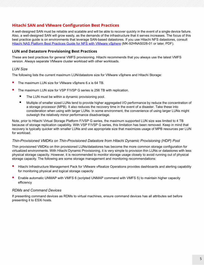
Figure 3 shows an example of a storage capability profile definition by VASA provider in the web user interface. Figure 4 shows an example virtual machine storage policy definition by VMware vSphere Web Client.
Figure 3
18
19
Figure 4
VMware Site Recovery Manager Best Practices These are the best practices for VMware Site Recovery Manager (SRM). Hitachi has two versions of the SRA.
Standard Storage SRM and Stretched Storage SRM with Global-active Device Best Practices
VMware vCenter Site Recovery Manager integrates tightly with Hitachi Storage arrays using either Hitachi Storage Replication Adapter (SRA) or the HDID-based SRA. This provides centralized management of recovery plans. Tight integration between storage arrays, VMware vCenter, VMware vCenter Site Recovery Manager, and Hitachi Storage Replication Adapter ensure a coordinated recovery for large, business critical environments.
Remote data replication is a key function in building out stable and reliable disaster recovery environments. Replicating data to a remote secondary site represents the most effective insurance policy against a catastrophic failure. Although you can perform data replication at the server level, you can perform data replication more effectively within the storage infrastructure.
The following are two types of underlying storage configurations supported by VMware SRM:
Standard storage (active-standby solution): leveraging Hitachi True Copy or Hitachi Universal Replicator
Stretched storage (active-active solution): leveraging global-active device on Hitachi Virtual Storage Platform
19

20
Table 4 lists the differences between two types of storage.
You may decide, depending on required RPO, which results in which replication type you choose.
For more information on the SRAs, see the following:
Hitachi Block Storage Replication Adapter for VMware vCenter Site Recovery Manager (SRM) – Deployment Guide
Hitachi Data Instance Director Adapter for VMware Site Recovery Manager (SRA)
VMware vSphere Metro Storage Cluster (vMSC) with GAD Best PracticesA VMware vSphere Metro Storage Cluster architecture on Hitachi Storage platforms provides an ideal solution for maximizing availability and uptime by clustering physical datacenters within metro distances. The metro storage cluster solution from Hitachi consists of storage systems presenting replicated storage as a single LUN from different geographically distributed sites. This design enables high availability of services by allowing virtual machine migration between sites with no downtime.
Changes in Multipathing and Path Configuration Best Practice
These are changes in multipathing and patch configuration best practices in a VMware vSphere Metro Storage Cluster environment.
Global-Active Device with Native Multipathing with ALUA
For a VMware Metro Storage Cluster configuration, global-active device with VMware native multipathing (NMP) with ALUA is supported with micro code 83-03-01-x0/00 and later. This feature allows you to present I/O to the remote site storage across long distances path that cause high response time by specifying it as non-optimized path. This minimizes response time and the cost of WAN traffic. It is recommended to turn on this feature with site distances greater than 20 miles (32 km).
TABLE 4. COMPARISON BETWEEN STANDARD STORAGE AND STRETCHED STORAGE
Type SRM with Standard Storage SRM with Stretched Storage
Business continuity
Site failover is required with down time even though planned migration such as site maintenance is being conducted.
During planned migration such as site maintenance, no disruption and down time occurs by using Cross-vCenter vMotion with Stretched storage is made up by global-active device and Hitachi Storage Replication Adapter.
Storage availability
Site failover is required due to primary storage failure.
It costs application downtime.
When primary storage failure occurs, no site failover is required by using the cross path to remote site storage which is virtualized as a single stretched storage and volume across the sites powered by global-active device technology.
Simplicity Simple because traditional disaster recovery configuration consists of primary storage and secondary storage.
In addition to traditional disaster recovery configuration, there is a need to consider quorum storage and additional paths between sites as cross-paths, and so forth. It tends to be more complex and larger.
20

21
Here is an example of enabling ALUA mode and specifying non-optimized path on Hitachi Storage:
raidcom modify ldev -ldev_id XXXXXX -alua enable
raidcom modify lun -port CLX-C-X -lun_id all -asymmetric_access_state non_optimized
Here is an example of enabling a SATP rule set as ALUA for Hitachi devices and selecting PSP as round robin on the VMware ESXi side:
Esxcli storage nmp satp rule add -V HITACHI -M “OPEN-V” -P VMW_PSP_RR -s VMW_SATP_ALUA -c tpgs_on
Hitachi recommends using RR (round robin) instead of MRU (most recently used).
With vSphere 6.7U1 and vSphere 6.5 P03 or later, this ALUA SATP rule is set by default. See this blog post for more details.
Uniform and Non-Uniform Host Access
While the Hitachi Storage Cluster for VMware vSphere solution supports uniform and non-uniform host access topology, Hitachi recommends uniform host access deployment where feasible for utmost high availability requirements.
Uniform host access configuration — This is when VMware ESXi hosts from both sites are all connected to a storage node in the storage cluster across all sites. Paths presented to ESXi hosts are stretched across this distance.
Non-uniform host access configuration — This is when VMware ESXi hosts in each site are connected only to storage node or nodes in the same site. Paths presented to ESXi hosts from storage nodes are limited to the local site.
Refer to Implement vSphere Metro Storage Cluster with Hitachi Virtual Storage Platform (VSP G/F) (2145375) for more information regarding to this topic.
3DC with VMware Site Recovery Manager Best PracticesThe 3DC solution consists of clustered primary and secondary datacenters leveraging global-active device in Hitachi Virtual Storage Platform, and the third data center which is replicated from the others as a disaster recovery site leveraging Hitachi Universal Replicator with delta resync functionality.
21

22
Hitachi Universal Replicator with delta resync functionality establishes storage remote replication from the primary data center to the third data center and from the secondary data center to the third data center respectively. This is called the global-active device 3DC delta resync environment, as shown in Figure 5.
Figure 5
Installing VMware Site Recovery Manager in this 3DC environment gives you the orchestrated and repeatable planned or unplanned migration or disaster recovery operations using a tested and proven recovery plan. This enables end-to-end virtual machine protection across 3 datacenters. As a normal state, VMware SRM protects the virtual machine between the primary and the third data center.
This solution is based on VMware Metro Storage Cluster, which clusters the primary and the secondary data centers within a single VMware vCenter data center object and uses stretched storage cluster powered by global-active device.
When the primary datacenter goes down, the virtual machine can be restarted on the secondary data center, leveraging VMware vSphere High Availability fail over functionality as a VMware Metro Storage configuration. During failover from the primary to secondary datacenter, storage remote replication established from the primary to the third data center is also automatically failed over to the other one established from the secondary to the third data center by leveraging delta resync functionality.
For a global-active device 3DC delta resync environment solution, the virtual machine protected by VMware SRM can follow this datacenter failover movement and re-protect the virtual machine between the secondary and third datacenter with minimal effort.
22

23
Note — As a normal state, VMware SRM protects the virtual machine between the primary and third datacenter. When the primary datacenter goes down, storage remote replication can automatically failover though, the re-protection of virtual machines by SRM requires some manual operation to switch the source and target datacenter. To do this, switching the command control interface configuration file and restarting the Hitachi Open Remote Control Manager daemon is required.
Referenced Infrastructure Products
Hitachi Virtual Storage Platform F Series and VSP G Series
Use Hitachi Virtual Storage Platform F series storage for an all flash-powered cloud platform for your mission critical applications. This storage meets demanding performance and uptime business needs.
Hitachi Virtual Storage Platform G series storage provides a hybrid media powered platform. It has a broad range of efficiency technologies that deliver maximum value while making ongoing costs more predictable. You can focus on strategic projects and consolidate more workloads while using a wide range of media choices.
Hitachi Storage Virtualization Operating System RF is at the heart of the Virtual Storage Platform F and VSP G series family. It provides storage virtualization, high availability, flash optimized performance, quality of service controls, and advanced data protection. This proven, mature software provides common features, management, and interoperability across the Hitachi portfolio. This means you can reduce migration efforts, consolidate assets, reclaim space, and extend product life.
Hitachi Unified Compute Platform
Hitachi Unified Compute Platform (UCP) is a converged system that provides the foundation for business transformation and IT modernization. It allows you to build a modern IT infrastructure than can host any application, at any scale, and at any location.
The Unified Compute Platform architecture consists of modular building blocks including VMware vSAN and external storage-based converged systems. Its components scale independently to provide you with greater configurability, flexibility, and agility. The solution may be configured to support traditional “systems of record” as well as cloud-native applications.
Hitachi Unified Compute Platform Advisor
Hitachi Unified Compute Platform Advisor (UCP Advisor) brings simplified IT administration to storage, converged, and hyperconverged systems and supports guided lifecycle management for the server, network, and storage elements within supported Unified Compute Platform systems.
it provides operational workflows for end-to-end provisioning of VMware ESXi hosts, bare metal hosts, datastores, and networking orchestration.
Hitachi Data Instance Director
Hitachi Data Instance Director (HDID) provides enterprise copy data management capabilities for VMware environments and uses automated intelligence to provide a layered SLA-driven modern data protection schema. It provides a managed snapshot offload-based solution for granular VM backup, cloning and recovery, and automated management of multi-datacenter replications and supports VADP-based backup. It integrates with VMware vSphere tags to provide tag-controlled backup and copy data management capabilities.
Hitachi Automation Director
Hitachi Automation Director provides configurable best-practice-based service templates for simple, application-specific provisioning of datacenter resources to databases, applications, and VDI environments. Built-in support for role-based access control means that, once established, these templates can be used to move to self-service provisioning.
23

1
Corporate Headquarters5355 Augustine DriveSanta Clara, CA 96054 USAHitachiVantara.com | community.HitachiVantara.com
Contact InformationUSA: 1-800-446-0744Global: 1-858-547-4526HitachiVantara.com/contact
Hitachi Vantara
© Hitachi Vantara Corporation, 2019. All rights reserved. HITACHI is a trademark or registered trademark of Hitachi, Ltd. Microsoft, Windows Server, and Microsoft Office are trademarks or registered trademarks of Microsoft Corporation. All other trademarks, service marks, and company names are properties of their respective owners
Notice: This document is for informational purposes only, and does not set forth any warranty, expressed or implied, concerning any equipment or service offered or to be offered by Hitachi Vantara Corporation.
MK-SL-145-00, March 2019
![HITACHI CAPITAL CORPORATION HITACHI … the purposes of Directive 2004/39/EC ... HITACHI CAPITAL CORPORATION HITACHI CAPITAL (UK) PLC HITACHI CAPITAL AMERICA CORP. [[] []](https://img.dokumen.tips/doc/110x75/5ad063b27f8b9a1d328e3da3/hitachi-capital-corporation-hitachi-the-purposes-of-directive-200439ec-.jpg)