Embed Size (px)
Citation preview

© 2017 IBRACON
Volume 10, Number 5 (October 2017) p. 985 – 997 • ISSN 1983-4195http://dx.doi.org/10.1590/S1983-41952017000500003
Optimization of the bending stiffness of beam-to-column and column-to-foundation connections in precast concrete structures
Otimização da rigidez à flexão das ligações viga-pilar e pilar-fundação em estruturas pré-moldadas de concreto
Abstract
Resumo
This work involved the structural optimization of precast concrete rigid frames with semi-rigid beam-to-column connections. To this end, several frames were simulated numerically using the Finite Element Method. Beams and columns were modeled using bar elements and their connections were modeled using spring elements, with variable bending stiffness. The objective function was based on the search of the least stiff connection able to ensure the global stability of the building. Lastly, a connection model with optimal stiffness was adopted to design the frame. Semi-rigid beam-to-column connections with a constraint factors of 0.33 sufficed to ensure the maximum allowable horizontal displacement and bending moment of the connection, with a global stability parameter of 1.12. This confirms that even connections with low constraints generate significant gains from the structural standpoint, without affecting construction and assembly-related aspects.
Keywords: numerical analysis, precast concrete, semi-rigid connections, structural optimization.
Este trabalho trata da otimização estrutural de pórticos planos em concreto pré-moldado com ligações semirrígidas entre vigas e pilares. Alguns pórticos foram simulados numericamente através do Método dos Elementos Finitos. Vigas e pilares foram modelados por elementos de barra e suas ligações com elementos de mola deformável à flexão. A função objetivo baseou-se na busca da menor rigidez da ligação capaz de aten-der a estabilidade global da edificação. Um modelo de ligação com rigidez ótima foi adotado para compor o pórtico. Observou-se que ligações semirrígidas entre viga e pilar com fatores de restrição de 0,33 foram suficientes para atender o deslocamento horizontal máximo permitido e o momento solicitante da ligação, atingindo um parâmetro de estabilidade global de 1,12. Isto comprova que mesmo ligações com baixas restrições geram ganhos significativos do ponto de vista estrutural, sem prejuízos dos aspectos construtivos e de montagem.
Palavras-chave: concreto pré-moldado, ligações semirrígidas, otimização estrutural.
a Postgraduate Program in Civil Engineering, School of Civil Engineering, Federal University of Uberlandia, Uberlândia, MG, Brazil.
Received: 04 Aug 2016 • Accepted: 23 Mar 2017 • Available Online: 04 Oct 2017
R. R. R. COSTA a
M. C. V. LIMA a
G. M. S. ALVA a
E. S. MAGALHÃES a

986 IBRACON Structures and Materials Journal • 2017 • vol. 10 • nº 5
Optimization of the bending stiffness of beam-to-column and column-to-foundation connections in precast concrete structures
1. Introduction
Brazil’s construction industry is notorious for its low productivity, ex-treme wastefulness of materials and low quality control. This sce-nario can be changed by using precast concrete structures (Figure 1), which render constructions more rational and economic (El Debs [1]).To disseminate this constructive system and provide resources and parameters for building designers, this paper describes a study on precast rigid frames composed of semi-rigid beam-to-column and column-to-foundation connections (see Figure 2), as specified by the Brazilian technical standard ABNT NBR 9062:2006 [2]. These connections are usually designed as joints or brackets, which is not always the case in real structures. In terms of the semi-rigidity of the connection, the actual behavior of the structure
is well represented by the structural model, which distributes the second-order moments of the columns to the beams, and even allows the dimensions of the cross-sectional areas of the elements to be scaled down, thus reducing their loads when compared to the hinge condition (Elliot et al. [3]). This paper has as main objective to do the optimization of the structural behavior of precast concrete slabs formed by semi-rigid connections, noting the importance of facilitating the construc-tive aspects. It is intended to demonstrate that a small increase in beam-to-column bending stiffness may be able to meet global stability requirements. So, this work aims to find the connections whose constraint factors are between 0.14 to 0.39, which can en-sure a semi-rigid behavior with low flexural strength, as proposed by Ferreira, El Debs and Elliot [4].A secondary objective was to investigate the effect of semi-rigid connections on the overall behavior of the structure regarding the distribution of forces and displacement and to recommend models of connections capable of meeting the optimum rigidity obtained. In the end, frames were simulated numerically and submitted to an optimization process using the Finite Element Method. The objective function was based on the search of the least stiff con-nection able to ensure the global stability of the building.
2. Semi-rigid connections
The semi-rigid behavior of a connection at the bending moment is characterized by its moment-rotation curve (Figure 3). This type of connection usually shows a nonlinear behavior even in elastic conditions (before the yielding of bars under tension). The physical nonlinearity of the connection can be simplified by using the secant stiffness /φ φ=s cr ck M (Figure 4), where crM is the bending mo-ment of the connection at the yield point of the tensioned reinforce-ment and φc is the rotation of the connection due to the crM mo-
Figure 1Structural system of precast concrete, El Debs [1]
Figure 2Semi-rigid beam-to-column connection, ABNT NBR 9062:2006 [2]
Figure 3Moment vs. rotation curve of the connection, El Debs [1]

987IBRACON Structures and Materials Journal • 2017 • vol. 10 • nº 5
R. R. R. COSTA | M. C. V. LIMA | G. M. S. ALVA | E. S. MAGALHÃES
ment (Ferreira, El Debs & Elliot [4]). The theoretical models for the design of semi-rigid connections proposed by these authors were compared with various experimental results of typical connections, which, in some cases, present a higher than 95% correlation be-tween theoretical and experimental values for the moment vs. rota-tion ratio, as highlighted by Elliot et al. [5].The secant stiffness, , φsk can be written as a constraint factor (αr ) of the connection, according to Equation [1], defined by the ABNT NBR 9062:2006 standard [2],
(1)where:
secEI is the secant stiffness of the beam, according to ABNT NBR 6118:2014 [6]; and
efl is the effective span length of the beam.Table 1 presents the classification of connections proposed by Fer-reira, El Debs and Elliot [4]. If the alpha value is higher than 0.85, the connection can already be considered perfectly rigid, accord-ing to the ABNT NBR 9062:2006 standard [2], and if it is lower than 0.15, the connection can be considered hinged.The best configuration for the frame, that can ensure its global stability as well as its easy implementation and feasible cost, can be determined by means of structural optimization.According to Mota [7], Meireles Neto [8], Alencar, Parente & Albu-querque [9] and Pinto et al. [10], a slight increase in connection stiffness significantly reduces lateral displacements and global second-order effects. So, the main goal of this study is to confirm this statement and investigate the effect of semi-rigid connections on the structure’s overall behavior in terms of load distribution and displacement.
3. Global stability
New technologies and new materials have allowed for the con-struction of buildings with a larger number of floors, with more slender and therefore less rigid elements. Thus, the effects of hori-zontal loads have become even more significant for the study of structural stability.Therefore, to ensure global structural stability requires a second-order analysis that considers the deformed position of the struc-ture. In this type of analysis, loads and displacements are not lin-early related with the forces, as in a first-order analysis. The displacement of the structure is important for both Ultimate Limit State (ULS) and Serviceability Limit State (SLS). In Ultimate
Limit State analysis, nodal displacement is classified according to structures with fixed nodes (if the second-order effects are less than 10% when compared to the first-order effects) and structures with moving nodes (if not). In the former, the second-order effects do not interfere significantly with the final loads. If the structure contains moving nodes, the loads originated by displacement from the starting position must be con-sidered, at the risk of loss of equilibrium or collapse of elements. The process of the g z coefficient (Equation [2]) is a way to deter-mine the need to consider global second-order effects by calculat-ing the multiplier coefficient of the first-order moment,
(2)
where:
1 dM is the first-order moment, in the foundation of the structure, generated by the forces that tend to lead to its collapse;DÄ dM is the moment generated by the active forces, which is cal-culated with the structure displaced by 1dM .
Figure 4Secant stiffness of the bending moment, adapted from ABNT NBR 9062:2006 [2]
Table 1Classification of the connections adapted from Ferreira, El Debs and Elliot [4]
Constraint factor αr Zone Classification
0 ≤ αr < 0.14 I Hinge and Pin
0.14 ≤ αr < 0.4 II Semi-rigid with low flexural strength
0.4 ≤ αr < 0.67 III Semi-rigid with intermediate flexural strength
0.67 ≤ αr < 0.86 IV Semi-rigid with high flexural strength
0.86 ≤ αr < 1 V Rigid

988 IBRACON Structures and Materials Journal • 2017 • vol. 10 • nº 5
Optimization of the bending stiffness of beam-to-column and column-to-foundation connections in precast concrete structures
If the value obtained for the gz coefficient is less than 1.1, the glob-al second-order effects can be disregarded (ABNT NBR 6118:2014 [6]). If the coefficient varies from 1.1 to 1.3, the moment dM is calculated by Equation [3],
(3)However, better calculation results of the moment dM are ob-tained by Equation [4], according to Moncayo [11].
(4)If the coefficient is found to be higher than 1.3, the global second-order effects must be considered by means of the P-Delta itera-tive process.
4. Structural optimization
In general, the optimization process generates a systematic meth-od to search for the best structural design, so as to reduce the de-signer’s intervention and become an independent tool of the user’s experience to reach the best situation.An optimization problem is well defined by three factors: – Design variables, which are the parameters that define the sys-
tem, such as, for example, the dimensions and properties of the materials involved;
– Design constraints, which establish limits or conditions that must be respected in the process of searching for the optimal result; and
– Objective function, which is a function of design variables. Its
minimum or maximum point is of interest in the iterative process.The ANSYS version 12.1 software program contains several opti-mization methods and tools that can be applied to the numerical model after its solution, as proposed by Menon [12] and Zhang, Zhong & Gao [13].After defining the design variables, the design constraints and the objective function, the process of searching for the optimal solution is initiated by means of one of the available methods. In this pa-per, we used the First Order Method, which uses information from the first derivative of functions. This is an effective method that defines precise directions to search for the optimal solution in the extensive design space, in which the design variables vary widely. The tools available in ANSYS and used in this study can be defined as follows: – Random Design Generation: performs repetitions/multiple itera-
tions with random values of the design variables. It is very use-ful to study the overall design space, and to establish possible designs sets for subsequent optimization analyses;
– Sweep Generation: generates sequences of various design sets, based on a reference design set. This tool enables evalu-ations of the global variation of the objective function and the constraint functions.
5. Numerical analysis
In this work, finite element models discretized in ANSYS version 12.1 were used to numerically simulate the rigid frame. The di-mensions of the frame’s base module (Figure 5) and characteristic loads (Table 2) were the same as those used by Meireles Neto [8]. Beams and columns were modeled using the uniaxial element
Figure 5Dimensions of the base module of the frame, Meireles Neto [8]

989IBRACON Structures and Materials Journal • 2017 • vol. 10 • nº 5
R. R. R. COSTA | M. C. V. LIMA | G. M. S. ALVA | E. S. MAGALHÃES
BEAM3. The columns were continuous and clamped at the base, while the beams were connected to the columns by the spring element COMBIN14, which considers only the rotation of the spring on the axis perpendicular to the plane. For these connections, the plane displacements were adjusted by the cou-pling control.The numerical analyses performed are illustrated in the flow chart schema shown in Figure 6. Accordingly, the ANSYS program was used to calculate the loads and displacements of the frame, con-
sidering the physical characteristics and geometry of the structural system. The process of structural optimization was initiated after determining the response of the structure to the given load. To perform the optimization routine in the ANSYS program, one begins by selecting the optimization method, after which one chooses the design variables, constraints, and objective function (lowest possible stiffness of the connection). Lastly, after determin-ing the minimum stiffness of the beam-to-column connections in terms of bending deformation, the connection is designed, and the final constraint factor and g z coefficient are calculated. It should be noted that after these analyses, the displacement at the top of the frame is checked in order to satisfy the ABNT NBR 9062:2006 standard [2].For the analysis of the Ultimate Limit State (ULS) situations, the most appropriate normal ultimate combination is expressed by Equation [5], which uses wind as the main variable force. Over-loads were admitted for places with high concentrations of people (Ψ0 =0.7).
(5)where:
G denotes the characteristics of permanent forces; W denotes the characteristics of wind forces; Q denotes the characteristics of overload.
The coefficients were adopted considering a type 2 commercial building, according to the ABNT NBR 8681:2003 standard [14].
Table 2Characteristic forces of the frame, adapted from Meireles Neto [8]
Permanent G(kN/m) 88.9 + self weight
of the beams
(kN) self weight of the columns
Overload Q (kN /m) 40
Wind W(kN)
5th floor 6.8
4th floor 13.1
3rd floor 12.4
2nd floor 11.6
1st floor 10.2
Figure 6Frame analysis flow chart schema

990 IBRACON Structures and Materials Journal • 2017 • vol. 10 • nº 5
Optimization of the bending stiffness of beam-to-column and column-to-foundation connections in precast concrete structures
Another aspect that must be checked is the maximum glob-al displacement, which, according to Table 2 of the ABNT NBR 9062:2006 standard [2], should be smaller than the /1200H ratio, where H is the total height of the building. To this end, it is recommended to use the frequent service combination. Equation [6] makes this combination, using wind as the primary variable of force and overload with its quasi-permanent value (Ψ2=0.4).
(6)For the approximate consideration of physical nonlinearity in ULS, column stiffness was reduced by the coefficient 0.7, while beam stiffness was reduced by the coefficient 0.4, as recommended by Ferreira and El Debs [15] for structures with a constraint factor ranging from 0.14 to 0.67.
5.1 Variation of the constraint factor of the connection
The global behavior of the frame for each αr value inside Zone II is illustrated in Figure 7. In the eight models simulated by ANSYS, three column cross-sec-tion dimensions were tested: 50 cm x 40 cm, 50 cm x 50 cm, and 80 cm x 40 cm, in which the first dimension 1( )d is arranged in the wind direction. For the inverted T-beams (Figure 8), the fol-lowing dimensions were evaluated: 31 cm x 50 cm, 31 cm x 48 cm, 35 cm x 48 cm, 31 cm x 60 cm, and 31 cm x 80 cm, where the first dimension corresponds to the base of the beam ( )vb and the second to its height ( )vh . The values of concrete compressive strength were also varied between 40 MPa and 50 MPa, to verify the reduction in the coefficient of global stability g z . Note that only the central portion of the beam’s cross section will be optimized. The dimensions of the two lateral flanges were fixed at 0.25 cm x 0.48 cm.
5.2 Optimization of the frame
After numerical modeling, the rigid frame was subjected to the opti-mization test. A combination of two tools and an optimization meth-od available in ANSYS were used for the convergence tests. The first tool (Random Generation Design) was used to test the random starting values for the design variables. The 1st order method was then applied, which uses information of the first derivative of the functions and sets precise directions to search for the optimal solu-tion in the extensive design space. Lastly, the Sweep Generation
Figure 7Behavior of the frame in response to Zone II constraint factors
Figure 8Cross-sections of the beams and columns of the frame
991IBRACON Structures and Materials Journal • 2017 • vol. 10 • nº 5
R. R. R. COSTA | M. C. V. LIMA | G. M. S. ALVA | E. S. MAGALHÃES
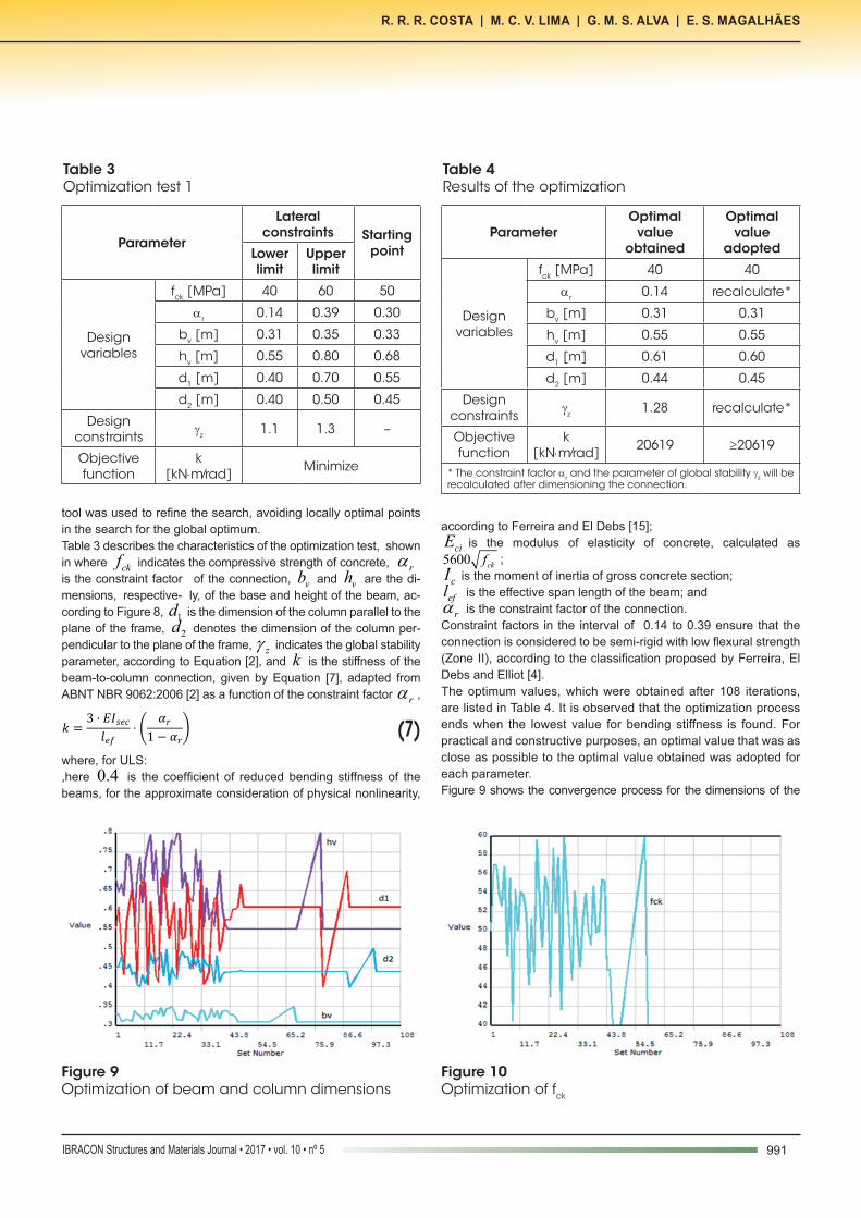
tool was used to refine the search, avoiding locally optimal points in the search for the global optimum.Table 3 describes the characteristics of the optimization test, shown in where ckf indicates the compressive strength of concrete, αris the constraint factor of the connection, vb and vh are the di-mensions, respective- ly, of the base and height of the beam, ac-cording to Figure 8, 1d is the dimension of the column parallel to the plane of the frame, 2d denotes the dimension of the column per-pendicular to the plane of the frame, g z indicates the global stability parameter, according to Equation [2], and k is the stiffness of the beam-to-column connection, given by Equation [7], adapted from ABNT NBR 9062:2006 [2] as a function of the constraint factor αr ,
(7)where, for ULS:,here 0.4 is the coefficient of reduced bending stiffness of the beams, for the approximate consideration of physical nonlinearity,
according to Ferreira and El Debs [15]; ciE is the modulus of elasticity of concrete, calculated as
5600 ckf ; cI is the moment of inertia of gross concrete section;
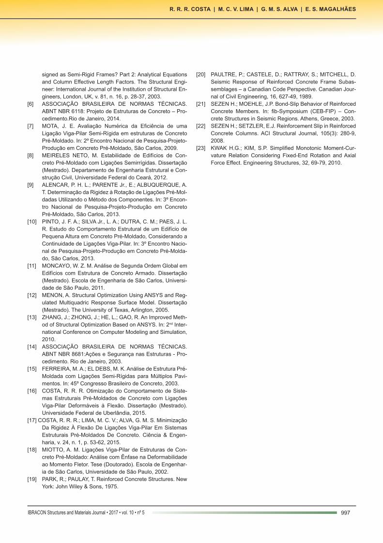
efl is the effective span length of the beam; andαr is the constraint factor of the connection.Constraint factors in the interval of 0.14 to 0.39 ensure that the connection is considered to be semi-rigid with low flexural strength (Zone II), according to the classification proposed by Ferreira, El Debs and Elliot [4].The optimum values, which were obtained after 108 iterations, are listed in Table 4. It is observed that the optimization process ends when the lowest value for bending stiffness is found. For practical and constructive purposes, an optimal value that was as close as possible to the optimal value obtained was adopted for each parameter.Figure 9 shows the convergence process for the dimensions of the
Table 3Optimization test 1
Parameter
Lateral constraints Starting
pointLower limit
Upper limit
Design variables
fck [MPa] 40 60 50
αr 0.14 0.39 0.30
bv [m] 0.31 0.35 0.33
hv [m] 0.55 0.80 0.68
d1 [m] 0.40 0.70 0.55
d2 [m] 0.40 0.50 0.45
Design constraints gz 1.1 1.3 –
Objective function
k[kN⋅m∕rad] Minimize
Table 4Results of the optimization
ParameterOptimal
value obtained
Optimal value
adopted
Design variables
fck [MPa] 40 40
αr 0.14 recalculate*
bv [m] 0.31 0.31
hv [m] 0.55 0.55
d1 [m] 0.61 0.60
d2 [m] 0.44 0.45
Design constraints gz 1.28 recalculate*
Objective function
k[kN⋅m∕rad] 20619 ≥20619
* The constraint factor αr and the parameter of global stability gz will be recalculated after dimensioning the connection.
Figure 9Optimization of beam and column dimensions
Figure 10Optimization of fck

992 IBRACON Structures and Materials Journal • 2017 • vol. 10 • nº 5
Optimization of the bending stiffness of beam-to-column and column-to-foundation connections in precast concrete structures
cross sections of beams and columns of the frame. The convergence of the values for concrete compressive strength ckf , for the con-straint factor of the connection αr , and the global stability parameter g z are illustrated in Figure 10 and Figure 11, respectively. Figure 12 depicts the search for lowest stiffness ( k ) of the beam-to-column connection, which satisfies the design constraints. Note that to satisfy the conditions imposed, the area of the cross-section of the columns was increased, since the minimum value for ckf was obtained.Costa [16] presents another optimization test aimed at satisfying the constraints by increasing the concrete compression strength, limiting the base of the beam ( vb ) to 31 cm and dimension 2d of the column to 40 cm.Costa, Lima and Alva [17] optimized a second rigid frame and demonstrated that semi-rigid connections with a constraint factor of about 0.37 are responsible for a reduction of 53% of the moment at the base of the columns and of 75% of the displacement at the top of the frame when compared with hinge and pin connections.
5.3 Connection under study
To satisfy the optimum value of the stiffness of the connection, we used the connection typologies studied by Miotto [18], consisting of continuous reinforcement, anchor and support pad, as depicted in Figure 13. The purpose of continuous reinforcement is to transfer the nega-tive moment acting on the connection, while the anchor and the pad are responsible for transferring the positive moment, depend-ing on the load. This connection was adopted for its simplicity of execution. Fur-thermore, the stiffness of this connection at the negative and posi-tive bending moment was studied by authors as Ferreira, El Debs & Elliot [4 and 15].Connections with continuous reinforcement are subject to two main strain mechanisms that cause relative rotations between beam and column, which are due to bending loading. The first mecha-nism involves slippage of the continuous reinforcement inside the column, and the second to the slippage induced by the formation of bending cracks at the end of the beam, whose length depends on the beam’s useful height. In the international literature, analyti-cal models that take into account the effect of these mechanisms are described by Park & Paulay [19], Paultre et al. [20] and, more recently, in the studies of Sezen & Moehle [21], Sezen & Setzler [22] and Kwak & Kim [23]. Ferreira, El Debs & Elliot [4] propose that the secant stiffness of the connection at the negative bending moment ( φnk ) should be calculated by Equation [8],
(8)
where:
el : embedment length of the continuous reinforcement inside the column;
pl : length of the region of the connection corresponding to half the bracket length plus the useful height d of the beam at the end of the support;
sE : longitudinal modulus of elasticity of the continuous reinforce-ment steel bar;
sA : area of the negative reinforcement passing through the column;
Figure 11Optimization of αr and gz
Figure 12Optimization of k
Figure 13Connection with continuous reinforcement, anchor and support pad, according to Miotto [16]

993IBRACON Structures and Materials Journal • 2017 • vol. 10 • nº 5
R. R. R. COSTA | M. C. V. LIMA | G. M. S. ALVA | E. S. MAGALHÃES
d : useful height at the end of the beam;
csE : secant modulus of elasticity of the concrete;
crI : moment of inertia of the homogenized cracked section in Zone II.To calculate the secant stiffness in positive bending ( φ pk ), Fer-reira and El Debs [15] recommend the use of Equation [9],
(9)
where:sE : longitudinal modulus of elasticity of the steel anchor;
d : useful height at the end of the beam;φb : anchor diameter;
ah : support pad thickness.Since the connections of the frame in question are not subjected to positive moment loads, these will not be calculated. However, the support pad and anchor will be used for the constructive purpose
of maintaining the stability and the best accommodation between beam and column.A nominal concrete layer of 3 cm, a 0.5 cm stirrup and a 40 cm long bracket were adopted. Tables 5 and 6 describe the aforementioned parameters and re-sults found for the beam-to-column connections for a central col-umn and corner column, respectively. Considering that the steel of the negative reinforcement is AC-50 grade, the ultimate strength RdM , calculated by Equation [10], is 314.09 kNm , while the calculated loading moment of the most loaded connection is 285.40 kNm .
(10)where:
RdM is the calculated loading moment in the connection; d is the useful height of the beam;
ydf is the calculated yield strength of the reinforcement steel used;
Table 5Connection for the central column
Moment Parameters Stiffness of the connection(k)
Constraint factor of the connection
(αr)
Negative
le 30 cm
68659.32kN⋅m ∕ rad 0.35
lp 69.9 cm
Es 210 GPa
As 2 ϕ 32 mm
d 49.9 cm
Ecs 30104.88 MPa
Icr 205432 cm4
Positiveϕb 7 mm
Construction purposeha 1 cm
Table 6Connection for the edge column
Moment Parameters Stiffness of the connection(k)
Constraint factor of the connection
(αr)
Negative
le 57 cm
57140.67kN⋅m ∕ rad 0.31
lp 69.9 cm
Es 210 GPa
As 2 ϕ 32 mm
d 49.9 cm
Ecs 30104.88 MPa
Icr 205432 cm4
Positiveϕb 7 mm
Construction purposeha 1 cm

994 IBRACON Structures and Materials Journal • 2017 • vol. 10 • nº 5
Optimization of the bending stiffness of beam-to-column and column-to-foundation connections in precast concrete structures
sA is the area of reinforcement steel in the connection; and SdM is the calculated loading moment in the connection.
Table 7 describes the model in terms of maximum global horizontal displacement, which is limited to /1200 H in Table 2 of the ABNT NBR 9062:2006 standard [2], where H corresponds to the total height of the building.Figure 14 shows the bending moment diagram of the frame with its final connections. Figure 15 depicts the ultimate displacement of the frame, analyzed in the SLS condition.Semi-rigid connections with an average constraint factor of 0.33 sufficed to satisfy the parameter of global stability, the loading mo-ment da connection and the ultimate displacement at the top of the frame.In the study developed by Meireles Neto [8], the same frame com-posed of 81 cm x 48 cm beams and 50 cm x 50 cm columns, with
ckf equal to 40 MPa, reached a 1.9 cm displacement at the top. In their case, the semi-rigid connections presented a constraint fac-tor of 0.30, contributing for the parameter of global stability (g z ) to reach a value of 1.34. In Table 7, it is clear that the displacements and the g z obtained here were much smaller than those reported by Meireles Neto [8]. This is due to the greater inertia of the beams and columns and the reinforcement employed to offset the loading moment in the connection used in this study.
Figure 14Diagram of bending moment (kN.m) on ULS conditions
5.4 Analysis of semi-rigid foundation
In order to evaluate the effect of the semi-rigidity of the column-to-foundation connections, the numerical model of the frame was modified by inserting the spring element COMBIN14 at the base of the columns. We considered only the rotation of the spring on the axis perpendicular to the plane of the frame, resulting from the elas-tic shortening of the piles, according to Equation [11]. In this study, ground deformability (vertical at the base of the piles and horizon-tal along their shaft) was not considered. Therefore, the nodes at the base of the columns were prevented from shifting by inserting a clamp immediately below the spring element (Figure 16),
(11)where:
eA refers to the sum of the cross-sectional areas of the piles; cE is the modulus of elasticity of concrete;
e refers to the distance between the axes of the piles; and el is the length of the piles.
The calculated stiffness of two piles with a diameter of 40 cm and length of 15 m, spaced 1.4 m apart, with a characteristic concrete compressive strength of 30 MPa, is 503643.6 kNm/rad.

995IBRACON Structures and Materials Journal • 2017 • vol. 10 • nº 5
R. R. R. COSTA | M. C. V. LIMA | G. M. S. ALVA | E. S. MAGALHÃES
The stiffness of the beam-to-column connections will be deter-mined by the optimization process. Finally, after determining the optimal values of the design vari-ables, the constraint factor for the column-to-foundation connec-tion can be calculated, according to Equation [12],
(12)
where: −sec columnEI is the secant stiffness of the column according to
ABNT NBR 6118:2014 [6]; and columnl is the length of the column.
The optimization applied to the modified frame with semi-rigid connections at the base of the columns had the same lateral con-
straints as those of the preceding process (Table 3). The same tools and optimization method were also applied.The optimal values determined and adopted in this study are de-scribed in Table 8. It should be noted that, when considering the semi-rigidity of column-to-foundation connections, the cross-sec-tion of the columns must be increased for a compensatory effect.Based on the optimal values that were adopted, the constraint factor of the column-to-foundation connection was calculated, ac-cording to Equation [11]. Table 9 lists the results obtained in the verification of the model.The adopted stiffness of the beam-to-column connection was equal to 26000 kNm/rad to account for the ultimate displacement at the top of the frame, which, according to the ABNT NBR 9062:2006 standard [2], should be smaller than or equal to /1200H , where H corresponds to the total height of the building.
Figure 15Displacement of the frame (m) on SLS conditions
Table 7Verification of the optimal model
Type of connection
k[kN⋅m ⁄ rad] αr
DMd[kN⋅m]
M1d[kN⋅m] gz
Dtop [cm](SLS)
Dultimate [cm] (SLS)
central 68659.32 0.35 5.31 50.45 1.12 0.165 1.35
edge 57140.67 0.31 5.31 50.45 1.12 0.165 1.35

996 IBRACON Structures and Materials Journal • 2017 • vol. 10 • nº 5
Optimization of the bending stiffness of beam-to-column and column-to-foundation connections in precast concrete structures
Table 9Verification of the modified optimal model
Type of connection
k[kN⋅m ⁄ rad] αr
DMd[kN⋅m]
M1d[kN⋅m] gz
Dtop [cm](SLS)
Dultimate [cm] (SLS)
C-F 503643.6 0.68 62.47 298.00 1.27 1.34 1.35
B-C 26000 0.17 62.47 298.00 1.27 1.34 1.35
C-F: represents the column-to-foundation connection; B-C: represents the beam-to-column connection.
Figure 16Model of frame with semi-rigid connections
6. Conclusions
This paper highlights the importance and advantages of the optimi-zation process applied to numerical modeling for structural analy-sis. The primary focus of this work was the search for optimized so-lutions in terms of the cross-sectional dimensions of the elements of structural framing systems, considering the possibility of using semi-rigid connections with low flexural strength, while ensuring that their easy construction and assembly is preserved, since this is one of the main advantages of using precast concrete elements. Only the benefits that are related to the simplicity of the construc-tive process are presented, believing that a simple process gener-ates lower costs.After modeling and optimizing the frame, the following conclusions can be drawn:– Increasing the stiffness of the connection, the concrete com-
pressive strength and the cross-sectional dimensions of the structural elements contributed to stiffen the frame and reduce the coefficient of global stability g z .
– The higher the constraint factor of the connection the lower the
moments at the base of the columns and the displacement at the top of the building.
– Semi-rigid beam-to-column connections with an average con-straint factor of 0.33 sufficed to satisfy the maximum horizontal displacement allowed, the loading moment of the connection, and to ensure a global stability parameter of 1.12. It is observed that the constraint factor is a characteristic of the adopted con-nection in this work. Furthermore, for higher frames, the global stability parameter tends to increase.
– The continuous reinforcement adopted for the connections sat-isfied their loading moment. This reinforcement, allied to the inertia of the beams and columns, enabled the displacement at the top of the building to be about 87% lower than the maximum allowable value.
– With regard to the semi-rigidity of the column-to-foundation con-nections, the optimization process involved an increase in the cross-section of the column as a way to stiffen the frame, offset-ting the effect generated by the connections at the base.
It was therefore demonstrated that connections with low flexural strength are able to ensure the global stability of the frame, rep-resenting a further advantage of precast concrete structures, be-cause they preserve the feasibility of building with these structures.
7. Acknowledgement
The authors gratefully acknowledge CAPES (Brazil’s Federal Agency for the Support and Improvement of Higher Education) for its financial support of this work.
8. References
[1] EL DEBS, M. K. Concreto Pré-moldado: Fundamentos e Aplicações. São Carlos. Projeto REENGE, EESC-USP, 2000.
[2] ASSOCIAÇÃO BRASILEIRA DE NORMAS TÉCNICAS. ABNT NBR 9062: Projeto e Execução de Estruturas de Con-creto Pré-Moldado. Rio de Janeiro, 2006.
[3] ELLIOT, K. S.; DAVIES, G.; GÖRGÜN, H.; ADLPARVAR, M. R. The Stability of Precast Concrete Skeletal Structures. PCI Journal, v. 43, n. 2, p. 42-60, 1998.
[4] FERREIRA, M. A.; EL DEBS, M. K.; ELLIOT, K. S. Modelo Teórico para Projeto de Ligações Semi-Rígidas em Estrutu-ras de Concreto Pré-Moldado. In: 44º Congresso Brasileiro de Concreto, 2002.
[5] ELLIOTT, K. S.; DAVIES, G.; FERREIRA, M. A.; GORGUN, H.; MADHI, A. A. Can Precast Concrete Structures be De-
997IBRACON Structures and Materials Journal • 2017 • vol. 10 • nº 5
R. R. R. COSTA | M. C. V. LIMA | G. M. S. ALVA | E. S. MAGALHÃES
signed as Semi-Rigid Frames? Part 2: Analytical Equations and Column Effective Length Factors. The Structural Engi-neer: International Journal of the Institution of Structural En-gineers, London, UK, v. 81, n. 16, p. 28-37, 2003.
[6] ASSOCIAÇÃO BRASILEIRA DE NORMAS TÉCNICAS. ABNT NBR 6118: Projeto de Estruturas de Concreto – Pro-cedimento.Rio de Janeiro, 2014.
[7] MOTA, J. E. Avaliação Numérica da Eficiência de uma Ligação Viga-Pilar Semi-Rígida em estruturas de Concreto Pré-Moldado. In: 2º Encontro Nacional de Pesquisa-Projeto-Produção em Concreto Pré-Moldado, São Carlos, 2009.
[8] MEIRELES NETO, M. Estabilidade de Edifícios de Con-creto Pré-Moldado com Ligações Semirrígidas. Dissertação (Mestrado). Departamento de Engenharia Estrutural e Con-strução Civil, Universidade Federal do Ceará, 2012.
[9] ALENCAR, P. H. L.; PARENTE Jr., E.; ALBUQUERQUE, A. T. Determinação da Rigidez à Rotação de Ligações Pré-Mol-dadas Utilizando o Método dos Componentes. In: 3º Encon-tro Nacional de Pesquisa-Projeto-Produção em Concreto Pré-Moldado, São Carlos, 2013.
[10] PINTO, J. F. A.; SILVA Jr., L. A.; DUTRA, C. M.; PAES, J. L. R. Estudo do Comportamento Estrutural de um Edifício de Pequena Altura em Concreto Pré-Moldado, Considerando a Continuidade de Ligações Viga-Pilar. In: 3º Encontro Nacio-nal de Pesquisa-Projeto-Produção em Concreto Pré-Molda-do, São Carlos, 2013.
[11] MONCAYO, W. Z. M. Análise de Segunda Ordem Global em Edifícios com Estrutura de Concreto Armado. Dissertação (Mestrado). Escola de Engenharia de São Carlos, Universi-dade de São Paulo, 2011.
[12] MENON, A. Structural Optimization Using ANSYS and Reg-ulated Multiquadric Response Surface Model. Dissertação (Mestrado). The University of Texas, Arlington, 2005.
[13] ZHANG, J.; ZHONG, J.; HE, L.; GAO, R. An Improved Meth-od of Structural Optimization Based on ANSYS. In: 2nd Inter-national Conference on Computer Modeling and Simulation, 2010.
[14] ASSOCIAÇÃO BRASILEIRA DE NORMAS TÉCNICAS. ABNT NBR 8681:Ações e Segurança nas Estruturas - Pro-cedimento. Rio de Janeiro, 2003.
[15] FERREIRA, M. A.; EL DEBS, M. K. Análise de Estrutura Pré-Moldada com Ligações Semi-Rígidas para Múltiplos Pavi-mentos. In: 45º Congresso Brasileiro de Concreto, 2003.
[16] COSTA, R. R. R. Otimização do Comportamento de Siste-mas Estruturais Pré-Moldados de Concreto com Ligações Viga-Pilar Deformáveis à Flexão. Dissertação (Mestrado). Universidade Federal de Uberlândia, 2015.
[17] COSTA, R. R. R.; LIMA, M. C. V.; ALVA, G. M. S. Minimização Da Rigidez À Flexão De Ligações Viga-Pilar Em Sistemas Estruturais Pré-Moldados De Concreto. Ciência & Engen-haria, v. 24, n. 1, p. 53-62, 2015.
[18] MIOTTO, A. M. Ligações Viga-Pilar de Estruturas de Con-creto Pré-Moldado: Análise com Ênfase na Deformabilidade ao Momento Fletor. Tese (Doutorado). Escola de Engenhar-ia de São Carlos, Universidade de São Paulo, 2002.
[19] PARK, R.; PAULAY, T. Reinforced Concrete Structures. New York: John Wiley & Sons, 1975.
[20] PAULTRE, P.; CASTELE, D.; RATTRAY, S.; MITCHELL, D. Seismic Response of Reinforced Concrete Frame Subas-semblages – a Canadian Code Perspective. Canadian Jour-nal of Civil Engineering, 16, 627-49, 1989.
[21] SEZEN H.; MOEHLE, J.P. Bond-Slip Behavior of Reinforced Concrete Members. In: fib-Symposium (CEB-FIP) – Con-crete Structures in Seismic Regions. Athens, Greece, 2003.
[22] SEZEN H.; SETZLER, E.J. Reinforcement Slip in Reinforced Concrete Columns. ACI Structural Journal, 105(3): 280-9, 2008.
[23] KWAK H.G.; KIM, S.P. Simplified Monotonic Moment-Cur-vature Relation Considering Fixed-End Rotation and Axial Force Effect. Engineering Structures, 32, 69-79, 2010.