Embed Size (px)
Citation preview

Optimiranje... B.-.R Höhn, K. Michaelis, M. Hinterstoißer
462 goriva i maziva, 48, 4 : 441-480, 2009.
Bernd-Robert Höhn, Klaus Michaelis and Michael Hinterstoißer
ISSN 0350-350X GOMABN 48, 4, 441-480
Izvorni znanstveni rad/Original scientific paper UDK 621.833.018 : 621.833-11 : 621.43.018.2 : 629.113 : 621.548.4 : .004.183
OPTIMIZATION OF GEARBOX EFFICIENCY Abstract Although mechanical gearboxes used as torque and speed converters have already very high efficiency it is not only a task in automotive applications to further decrease gearbox power losses but also in many industrial applications. Different methods are discussed for power loss reduction in a gearbox. No load losses can be reduced, especially at low temperatures and part load conditions when using low viscosity oils with a high viscosity index and low oil immersion depth of the components. This in turn influences the cooling properties in the gear and bearing meshes. Bearing systems can be optimized when using more efficient systems than cross loading arrangements with high preload. Low loss gears can contribute substantially to load dependent power loss reduction in the gear mesh. Low friction oils are available for further reduction of gear and bearing mesh losses. All in all a reduction of the gearbox losses in average of 50 % is technically feasible. The challenge is substantial power loss reduction with only minor impact on load carrying capacity, component size and weight and noise generation. Adequate compromises have to be proposed.
INTRODUCTION Future energy shortages have not only to be fought with exploitation of new renewable energy resources but also with reduction of energy consumption in all technical fields. For automotive applications optimisation attempts are made in all operating areas and for all components of vehicles to achieve minimum fuel consumption. Weight reduction and thermal management are possible approaches as well as hybrid systems and mechanical and software features for high efficient engines. Power loss reduction at the end of the power train has a large impact on overall optimization although absolute efficiency in gearboxes and rear axles is already high, (Xu, 2007). However, 1 kilowatt savings in the gearbox mean 4 kilowatts savings in fuel energy. Looking at wind turbines as a growing market for alternative energy production a modern equipment of the 5 megawatt class consist of 8 or more gear meshes and more than 12 bearing meshes. A reduction of the overall losses by 50 % would save some 200 kW power losses per wind turbine unit.

B.-.R Höhn, K. Michaelis, M. Hinterstoißer Optimiranje...
goriva i maziva, 48, 4 : 441-480, 2009. 463
The challenges are therefore a substantial power loss reduction with only minor impact on load carrying capacity, component size and weight and noise generation.
BASIC CONSIDERATIONS Power loss in a gearbox consists of gear, bearing, seal and auxiliary losses (Fig. 1). Gear and bearing losses can be separated in no load losses which occur even without power transmission, and load dependent losses in the contact of the power transmitting components. Besides operating conditions and internal housing design no load losses are mainly related to lubricant viscosity and density as well as immersion depth of the components of a sump lubricated gearbox (Changenet, 2007). Load losses depend on transmitted load, coefficient of friction and sliding velocity in the contact areas of the components.
Fig. 1: Composition of transmission power loss
For nominal power transmission the load losses of the gear mesh are typically dominant. For part load and high speed high no load losses dominate total losses. For an optimisation of the whole operating range of a gearbox load losses and no load losses have to be addressed. In the following the major contributors to gearbox power losses namely bearings and gears are considered.
BEARING POWER LOSS No load bearing losses depend on bearing type and size, bearing arrangement, lubricant viscosity and supply. Lowest no load losses of radial bearings are expected for cylindrical roller bearings. The also low values of taper roller bearings are valid for unloaded bearing arrangements, however, for the typical cross loading bearing arrangement axial preloading is required. This requirement of preload in a cross locating bearing arrangement with taper roller bearings increases the no load losses substantially.
Optimiranje... B.-.R Höhn, K. Michaelis, M. Hinterstoißer
464 goriva i maziva, 48, 4 : 441-480, 2009.
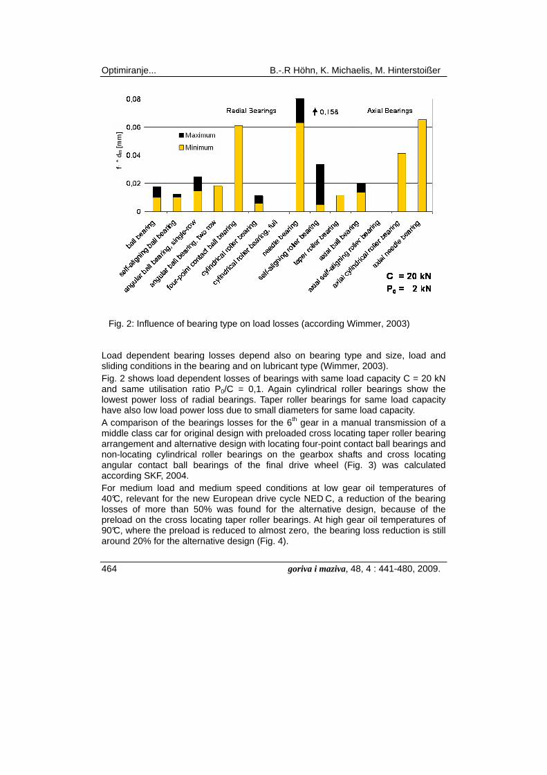
Fig. 2: Influence of bearing type on load losses (according Wimmer, 2003)
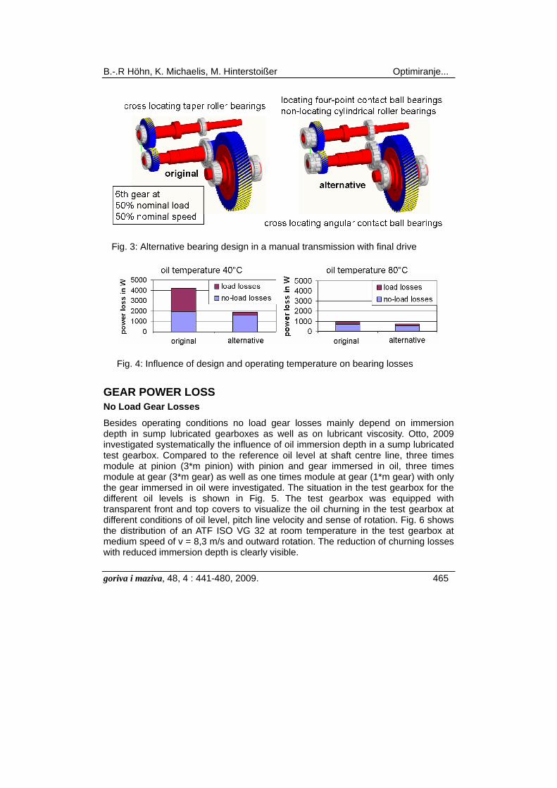
Load dependent bearing losses depend also on bearing type and size, load and sliding conditions in the bearing and on lubricant type (Wimmer, 2003). Fig. 2 shows load dependent losses of bearings with same load capacity C = 20 kN and same utilisation ratio P0/C = 0,1. Again cylindrical roller bearings show the lowest power loss of radial bearings. Taper roller bearings for same load capacity have also low load power loss due to small diameters for same load capacity. A comparison of the bearings losses for the 6th gear in a manual transmission of a middle class car for original design with preloaded cross locating taper roller bearing arrangement and alternative design with locating four-point contact ball bearings and non-locating cylindrical roller bearings on the gearbox shafts and cross locating angular contact ball bearings of the final drive wheel (Fig. 3) was calculated according SKF, 2004. For medium load and medium speed conditions at low gear oil temperatures of 40°C, relevant for the new European drive cycle NED C, a reduction of the bearing losses of more than 50% was found for the alternative design, because of the preload on the cross locating taper roller bearings. At high gear oil temperatures of 90°C, where the preload is reduced to almost zero, the bearing loss reduction is still around 20% for the alternative design (Fig. 4).
B.-.R Höhn, K. Michaelis, M. Hinterstoißer Optimiranje...
goriva i maziva, 48, 4 : 441-480, 2009. 465
Fig. 3: Alternative bearing design in a manual transmission with final drive
Fig. 4: Influence of design and operating temperature on bearing losses
GEAR POWER LOSS No Load Gear Losses
Besides operating conditions no load gear losses mainly depend on immersion depth in sump lubricated gearboxes as well as on lubricant viscosity. Otto, 2009 investigated systematically the influence of oil immersion depth in a sump lubricated test gearbox. Compared to the reference oil level at shaft centre line, three times module at pinion (3*m pinion) with pinion and gear immersed in oil, three times module at gear (3*m gear) as well as one times module at gear (1*m gear) with only the gear immersed in oil were investigated. The situation in the test gearbox for the different oil levels is shown in Fig. 5. The test gearbox was equipped with transparent front and top covers to visualize the oil churning in the test gearbox at different conditions of oil level, pitch line velocity and sense of rotation. Fig. 6 shows the distribution of an ATF ISO VG 32 at room temperature in the test gearbox at medium speed of v = 8,3 m/s and outward rotation. The reduction of churning losses with reduced immersion depth is clearly visible.

Optimiranje... B.-.R Höhn, K. Michaelis, M. Hinterstoißer
466 goriva i maziva, 48, 4 : 441-480, 2009.
Fig. 5: Immersion depth in test gearbox (according Otto, 2009)
Fig. 6: Gear churning as a function of immersion depth (according Otto, 2009)
B.-.R Höhn, K. Michaelis, M. Hinterstoißer Optimiranje...
goriva i maziva, 48, 4 : 441-480, 2009. 467
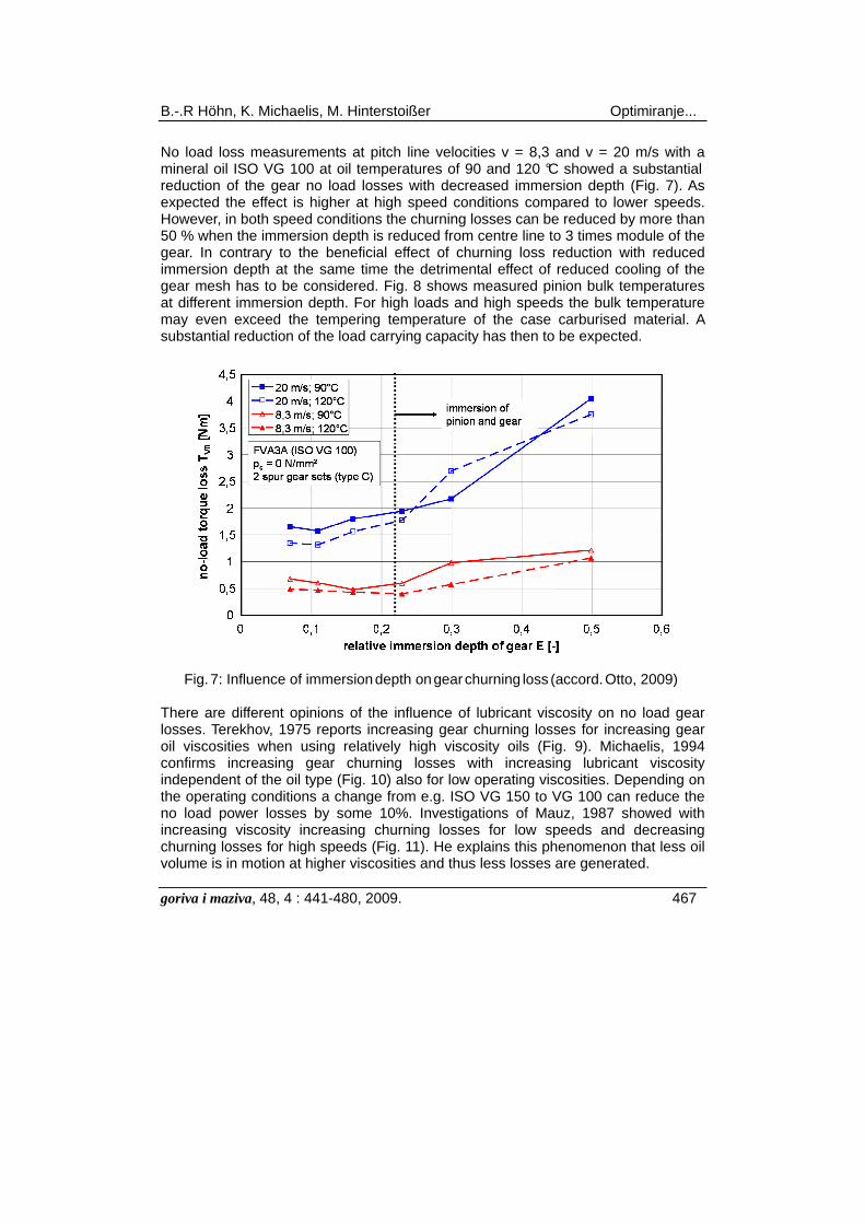
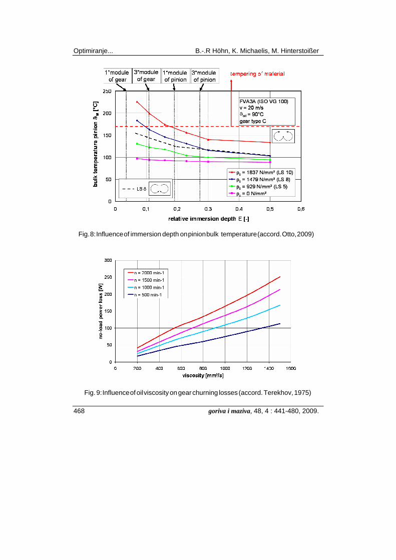
No load loss measurements at pitch line velocities v = 8,3 and v = 20 m/s with a mineral oil ISO VG 100 at oil temperatures of 90 and 120 °C showed a substantial reduction of the gear no load losses with decreased immersion depth (Fig. 7). As expected the effect is higher at high speed conditions compared to lower speeds. However, in both speed conditions the churning losses can be reduced by more than 50 % when the immersion depth is reduced from centre line to 3 times module of the gear. In contrary to the beneficial effect of churning loss reduction with reduced immersion depth at the same time the detrimental effect of reduced cooling of the gear mesh has to be considered. Fig. 8 shows measured pinion bulk temperatures at different immersion depth. For high loads and high speeds the bulk temperature may even exceed the tempering temperature of the case carburised material. A substantial reduction of the load carrying capacity has then to be expected.
Fig. 7: Influence of immersion depth on gear churning loss (accord. Otto, 2009) There are different opinions of the influence of lubricant viscosity on no load gear losses. Terekhov, 1975 reports increasing gear churning losses for increasing gear oil viscosities when using relatively high viscosity oils (Fig. 9). Michaelis, 1994 confirms increasing gear churning losses with increasing lubricant viscosity independent of the oil type (Fig. 10) also for low operating viscosities. Depending on the operating conditions a change from e.g. ISO VG 150 to VG 100 can reduce the no load power losses by some 10%. Investigations of Mauz, 1987 showed with increasing viscosity increasing churning losses for low speeds and decreasing churning losses for high speeds (Fig. 11). He explains this phenomenon that less oil volume is in motion at higher viscosities and thus less losses are generated.
Optimiranje... B.-.R Höhn, K. Michaelis, M. Hinterstoißer
468 goriva i maziva, 48, 4 : 441-480, 2009.
Fig. 8: Influence of immersion depth on pinion bulk temperature (accord. Otto, 2009)
Fig. 9: Influence of oil viscosity on gear churning losses (accord. Terekhov, 1975)

B.-.R Höhn, K. Michaelis, M. Hinterstoißer Optimiranje...
goriva i maziva, 48, 4 : 441-480, 2009. 469
Fig. 10: Influence of oil viscosity on gear churning losses (accord. Michaelis, 1994)
Fig. 11: Influence of oil viscosity on gear churning losses (accord. Mauz, 1987)
Optimiranje... B.-.R Höhn, K. Michaelis, M. Hinterstoißer
470 goriva i maziva, 48, 4 : 441-480, 2009.
Load Gear Losses The load gear losses PVZP in the mesh while power is transmitted follow the basic Coulomb law
(1)
with PVZP kW load gear losses FR kN friction force vrel m/s relative velocity
The local friction force in the gear mesh can be calculated from the local normal force and the local coefficient of friction along the path of contact
(2)
with PVZP kW load gear losses FN kN normal force µ - friction coefficient vg m/s sliding velocity
When Eq. (2) is multiplied with FNmax/FNmax * v/v =1 it reads
(3)
The distribution of the local relative parameters FN(x)/FNmax, µ(x) and vg(x)/v is shown in Fig. 12. With the linear dependence of load and sliding speed and the approximation of a constant friction coefficient along the path of contact Eq. (3) can be rewritten and rearranged to
(4)
with PVZP kW load gear losses Ftmax kN tangential force v m/s pitch line velocity
µmz - mean coefficient of gear friction αwt ° working pressure angle pet mm transverse pitch FN kN normal force.
vg m/s sliding velocity
P F x v xVZP R rel= ⋅( ) ( )
P F x x v xVZP N g= ⋅ ⋅( ) ( ) ( )µ
P FF xF
x vv x
vVZP NN
N
g= ⋅ ⋅ ⋅ ⋅maxmax
( )( )
( )µ
P F vp
F xF
v x
vdxVZP t mz
wt et
N
N
g
A
E
= ⋅ ⋅ ⋅ ⋅ ⋅ ⋅
∫max
maxcos( )( ) ( )
µα
1 1

B.-.R Höhn, K. Michaelis, M. Hinterstoißer Optimiranje...
goriva i maziva, 48, 4 : 441-480, 2009. 471
Fig. 12: Load, friction coefficient and sliding speed along path of contact Ohlendorf, 1958 introduced a loss factor HV which depends on geometrical gear data
( ) ( )Hp
F xF
v x
vdx
uz uV
wt et
N
N
g
A
E
b
= ⋅ ⋅ ⋅
=
⋅ +⋅ ⋅
⋅ − + +∫1 1 1
11
12
22
cos( )( ) ( )
cos( )maxαπ
β ε ε εα (5)
with HV - gear loss factor u - gear ratio z2/z1 z1 - number of teeth pinion ßb ° helix angle at base cylinder εα - profile contact ratio ε1, 2 - tip contact ratio, pinion and gear
The load gear losses can then be written
(6)
with PVZP kW load gear losses Pa kW transmitted power
µmz - mean coefficient of gear friction HV - gear loss factor
Low mesh losses can be achieved when the gear contact is concentrated around the pitch point with zero sliding (Fig.12) and a low value of the coefficient of gear friction. Lowloss gears with minimum sliding were designed in comparison to FZG standard test gears type C (Table 1). For same nominal load capacity calculated according to DIN 3990 a wider face width is required for lowloss gears compared to standard gear design. It has to be mentioned that load capacity calculation according to DIN 3990 is no longer valid due to values of pressure angle and profile
P P HVZP a mz V= ⋅ ⋅µ
Optimiranje... B.-.R Höhn, K. Michaelis, M. Hinterstoißer
472 goriva i maziva, 48, 4 : 441-480, 2009.
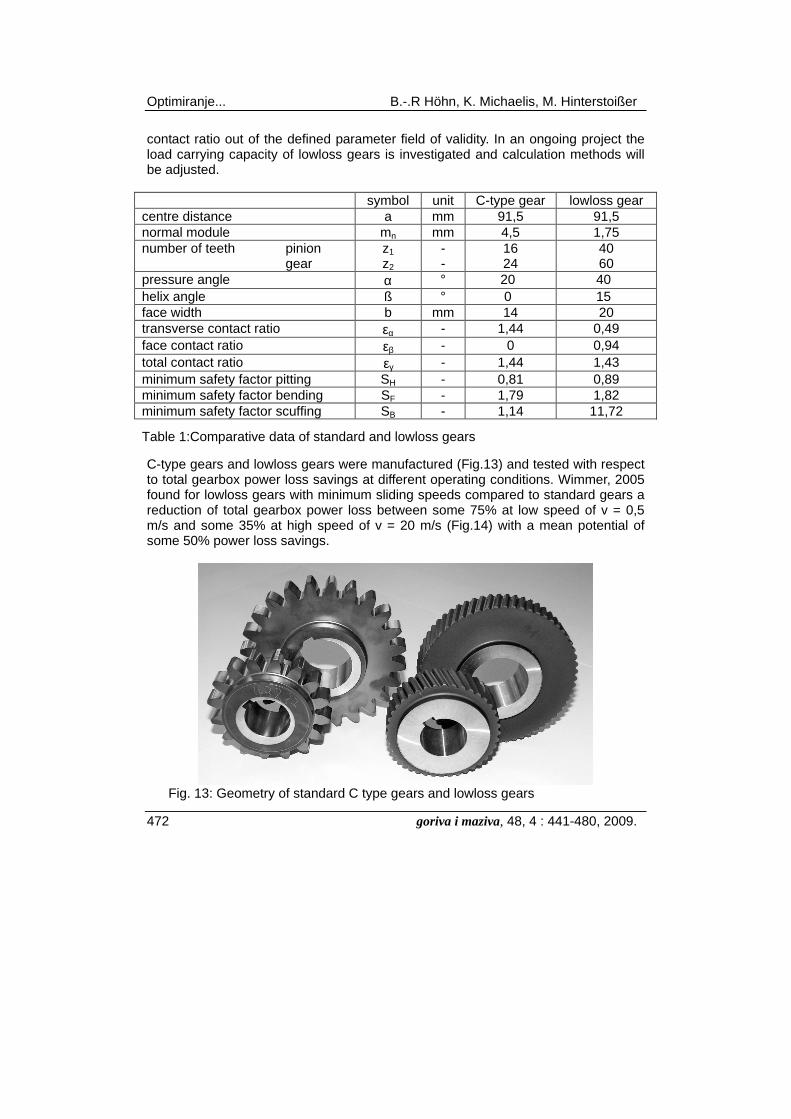
contact ratio out of the defined parameter field of validity. In an ongoing project the load carrying capacity of lowloss gears is investigated and calculation methods will be adjusted.
symbol unit C-type gear lowloss gear centre distance a mm 91,5 91,5 normal module mn mm 4,5 1,75 number of teeth pinion gear
z1 z2
- -
16 24
40 60
pressure angle α ° 20 40 helix angle ß ° 0 15 face width b mm 14 20 transverse contact ratio εα - 1,44 0,49 face contact ratio εβ - 0 0,94 total contact ratio εγ - 1,44 1,43 minimum safety factor pitting SH - 0,81 0,89 minimum safety factor bending SF - 1,79 1,82 minimum safety factor scuffing SB - 1,14 11,72
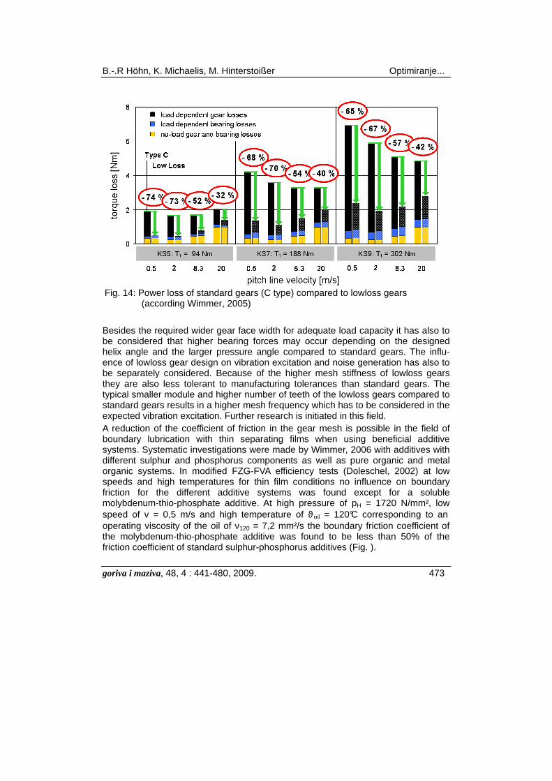
Table 1:Comparative data of standard and lowloss gears C-type gears and lowloss gears were manufactured (Fig.13) and tested with respect to total gearbox power loss savings at different operating conditions. Wimmer, 2005 found for lowloss gears with minimum sliding speeds compared to standard gears a reduction of total gearbox power loss between some 75% at low speed of v = 0,5 m/s and some 35% at high speed of v = 20 m/s (Fig.14) with a mean potential of some 50% power loss savings.
Fig. 13: Geometry of standard C type gears and lowloss gears
B.-.R Höhn, K. Michaelis, M. Hinterstoißer Optimiranje...
goriva i maziva, 48, 4 : 441-480, 2009. 473
Fig. 14: Power loss of standard gears (C type) compared to lowloss gears
(according Wimmer, 2005)
Besides the required wider gear face width for adequate load capacity it has also to be considered that higher bearing forces may occur depending on the designed helix angle and the larger pressure angle compared to standard gears. The influ-ence of lowloss gear design on vibration excitation and noise generation has also to be separately considered. Because of the higher mesh stiffness of lowloss gears they are also less tolerant to manufacturing tolerances than standard gears. The typical smaller module and higher number of teeth of the lowloss gears compared to standard gears results in a higher mesh frequency which has to be considered in the expected vibration excitation. Further research is initiated in this field. A reduction of the coefficient of friction in the gear mesh is possible in the field of boundary lubrication with thin separating films when using beneficial additive systems. Systematic investigations were made by Wimmer, 2006 with additives with different sulphur and phosphorus components as well as pure organic and metal organic systems. In modified FZG-FVA efficiency tests (Doleschel, 2002) at low speeds and high temperatures for thin film conditions no influence on boundary friction for the different additive systems was found except for a soluble molybdenum-thio-phosphate additive. At high pressure of pH = 1720 N/mm², low speed of v = 0,5 m/s and high temperature of ϑoil = 120°C corresponding to an operating viscosity of the oil of ν120 = 7,2 mm²/s the boundary friction coefficient of the molybdenum-thio-phosphate additive was found to be less than 50% of the friction coefficient of standard sulphur-phosphorus additives (Fig. ).

Optimiranje... B.-.R Höhn, K. Michaelis, M. Hinterstoißer
474 goriva i maziva, 48, 4 : 441-480, 2009.
Fig. 15: Influence of additive type on gear mesh loss (accord. Wimmer, 2006)
In the operating range of predominantly mixed and EHD friction a large influence of the base oil type on gear mesh friction is found. Doleschel, 2003 investigated different base oil types at different viscosity grades including expected high friction of a traction fluid (MYH 68) and a polyether based low friction fluid (MYL 68).
Fig. 16: Influence of base oil on gear mesh loss (according Doleschel, 2003)

B.-.R Höhn, K. Michaelis, M. Hinterstoißer Optimiranje...
goriva i maziva, 48, 4 : 441-480, 2009. 475
The range of the measured values for the coefficient of friction in the FZG-FVA efficiency test is shown in Fig.16. In a wide range of operating conditions friction in a gear mesh can be reduced compared to lubrication with a mineral oil by some 10 to 20% with a polyalphaolefin plus ester, by some 20 to 30% with a polyglycol and even by some 50% with a polyether type base oil compared to a mineral oil. Similar effects are expected for the different base oil types for the load dependent bearing losses.
APPLICATION Wind Turbine Gearbox
A very simple means of power loss reduction is the use of an efficient lubricant. For a quantitative evaluation of the influence of different lubricants on gearbox power loss a middle sized wind turbine gearbox with nominal power capacity of P = 1,8 MW was investigated. The gearbox with a planetary low speed first stage and an intermediate and high speed cylindrical gear stage was modelled in the computer program WTplus (Kurth, 2008) (Fig. 17). The program calculates the expected power loss of gears, bearings and seals for any gearing system. The influence of the lubricant can be introduced into the calculation with the evaluation of the friction coefficient of the lubricant according to Doleschel, 2002. From the results of the FZG-FVA efficiency test for the candidate oil at different operating conditions an empirical equation is derived for the calculation of the mesh friction in gears and bearings.
Fig. 17: Model of wind turbine gear system in WTplus
The friction coefficient µM in a gear mesh consists of a portion of solid body friction µF and a portion of fluid film friction µEHD:

Optimiranje... B.-.R Höhn, K. Michaelis, M. Hinterstoißer
476 goriva i maziva, 48, 4 : 441-480, 2009.
(7)
with µM - mixed friction coefficient µF - solid friction coefficient
µEHD - fluid friction coefficient ζ - portion of fluid friction
0 0,5 1,0 1,5 2,0 2,5
solid friction
fluid friction
relative film thickness λ
por
tion
in
%ζ
100
8060
40
200
Fig. 18: Fluid and solid friction in an EHD contact (accord. Doleschel, 2003)
The portion ζ of fluid and solid friction depends on the relative film thickness λ in the contact (Fig. 18). The solid friction coefficient and the fluid friction coefficient can be calculated according to Eqs. (8) and (9) with the parameters for the lubricant from the FZG-FVA efficiency test:
(8)
with µF - solid friction coefficient µF,R - solid friction coefficient, reference value from test
pH N/mm² contact pressure pR N/mm² reference value of contact pressure pR = 1000 N/mm² vΣ m/s sum velocity vR,F m/s reference value of speed for solid friction vR,F = 0,2 m/s αF - pressure exponent for solid friction from test βF - speed exponent for solid friction from test
µ µα β
F F RH
R R F
pp
vv
F F
= ⋅
⋅
,,
Σ
µ ζ µ ζ µM F EHD= − ⋅ + ⋅( )1

B.-.R Höhn, K. Michaelis, M. Hinterstoißer Optimiranje...
goriva i maziva, 48, 4 : 441-480, 2009. 477
(9)
with µEHD - fluid friction coefficient µEHD,R - fluid friction coefficient, reference value from test
pH N/mm² contact pressure pR N/mm² reference value of contact pressure pR = 1000 N/mm² vΣ m/s sum velocity vR,EHD m/s reference value of speed for fluid friction vR,F = 8,3 m/s αEHD - pressure exponent for fluid friction from test βEHD - speed exponent for fluid friction from test γEHD - viscosity exponent for fluid friction from test
For three different lubricants from the market place typical for wind turbine application the FZG-FVA efficiency test was performed. The relevant lubricant data can be taken from Table 2. The lubricants had all the same viscosity grade, ISO VG 320, with different base oil types: a mineral oil MIN320, a polyalphaolefin PAO320 and a polyglycol PG320 with typical additive packages for the application. The results of the comparative calculation for nominal power transmission are shown in Fig. 19. When changing from a mineral oil to a polyalphaolefin a reduction of power losses of some 10 % are possible, with a polyglycol even a 20 % reduction of power loss is feasible. symbol unit M320 PAO 320 PAG 320 type mineral poly-alpha-
olefin poly- glycol
viscosity ν40 ν100
mm²/s mm²/s
327 24,4
310 37,0
340 60
viscosity index VI - 97 169 247 density ρ15 kg/dm³ 898 902 1050 reference solid friction
µF,R - 0,047 0,060 0,048
solid friction exponents
αF ßF
- -
0,62 -0,12
0,74 -0,27
1,55 -1,60
reference fluid friction
µEHD,R - 0,033 0,022 0,016
fluid friction exponents
αF ßF γF
- - -
0,19 -0,05 0,19
0,59 -0,07 0,21
-0,11 0,01 0,40
Table 2: Lubricant data There is an even higher potential of efficiency gain when different viscosity grades are used according to the different viscosity-temperature behaviour of these oils. For
µ µηη
α β γ
EHD EHD RH
R R EHD
oil
R
pp
vv
EHD EHD EHD
= ⋅
⋅
⋅
,
,
Σ

Optimiranje... B.-.R Höhn, K. Michaelis, M. Hinterstoißer
478 goriva i maziva, 48, 4 : 441-480, 2009.
further efficiency improvements the expected film thickness values have to be analyzed taking viscosity and pressure viscosity at the expected gear temperature for the different lubricants into account.
Fig. 19: Calculated power loss with different lubricant types for a wind turbine gearbox
Fig. 20: Manual transmission (according Kurth, 2009)
B.-.R Höhn, K. Michaelis, M. Hinterstoißer Optimiranje...
goriva i maziva, 48, 4 : 441-480, 2009. 479
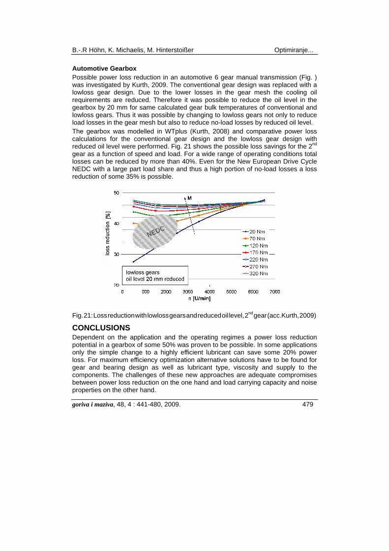
Automotive Gearbox Possible power loss reduction in an automotive 6 gear manual transmission (Fig. ) was investigated by Kurth, 2009. The conventional gear design was replaced with a lowloss gear design. Due to the lower losses in the gear mesh the cooling oil requirements are reduced. Therefore it was possible to reduce the oil level in the gearbox by 20 mm for same calculated gear bulk temperatures of conventional and lowloss gears. Thus it was possible by changing to lowloss gears not only to reduce load losses in the gear mesh but also to reduce no-load losses by reduced oil level. The gearbox was modelled in WTplus (Kurth, 2008) and comparative power loss calculations for the conventional gear design and the lowloss gear design with reduced oil level were performed. Fig. 21 shows the possible loss savings for the 2nd gear as a function of speed and load. For a wide range of operating conditions total losses can be reduced by more than 40%. Even for the New European Drive Cycle NEDC with a large part load share and thus a high portion of no-load losses a loss reduction of some 35% is possible.
Fig. 21: Loss reduction with lowloss gears and reduced oil level, 2nd gear (acc.Kurth, 2009)
CONCLUSIONS Dependent on the application and the operating regimes a power loss reduction potential in a gearbox of some 50% was proven to be possible. In some applications only the simple change to a highly efficient lubricant can save some 20% power loss. For maximum efficiency optimization alternative solutions have to be found for gear and bearing design as well as lubricant type, viscosity and supply to the components. The challenges of these new approaches are adequate compromises between power loss reduction on the one hand and load carrying capacity and noise properties on the other hand.
Optimiranje... B.-.R Höhn, K. Michaelis, M. Hinterstoißer
480 goriva i maziva, 48, 4 : 441-480, 2009.
References Changenet, C.; Velex, P.: Housing influence on churning losses in geared transmissions, ASME 2007. Doleschel, A., Höhn, B.-R., Michaelis, K.: Frictional Behaviour of Synthetic Gear Lubricants. 27th Leeds-Lyon Symposium on Tribology in Lyon, September 5-8, 2000, p. 759 - 768. Doleschel, A.: Method to Determine the Frictional Behaviour of Gear Lubricants using a FZG Gear Test Rig. FVA Information Sheet No. 345, March 2002. Doleschel, A.: Wirkungsgradberechnung von Zahnradgetrieben in Abhängigkeit vom Schmierstoff. Diss. TU München, 2003. Kurth, F.: FVA EDV-Programm WTplus – Benutzeranleitung. Forschungsvereinigung Antriebstechnik, Frankfurt 2008. Kurth, F., Höhn, B.-R., Michaelis, K.: Wirkungsgrad- und Leistungsflussanalysen für Handschalt- und Doppelkupplungsgetriebe. 1. Automobiltechnisches Kolloquium München, 16. – 17.04.2009, VDI Wissensforum Düsseldorf. Mauz, W.: Hydraulische Verluste von Stirnradgetrieben bei Umfangsgeschwindigkeiten bis 60 m/s. Diss. Universität Stuttgart, 1987. Michaelis, K., Winter, H.: Influence of Lubricants on Power Loss of Cylindrical Gears. 48th Annual Meeting in Calgary, Alberta, Canada, May 17-20, 1993. Tribology Transactions Vol. 37 (1994) p. 161-167. Ohlendorf, H.: Verlustleistung und Erwärmung von Stirnrädern. Diss. TU München, 1958. SKF-GRUPPE (Hrsg.): SKF Hauptkatalog 2004. Media-Print Informationstechnologie, Paderborn, 2004. Terekhov, A.S.: Hydraulic losses in gearboxes with oil immersion. Vestnic Mashinostroeniya, Vol. 55, Issue 5, 1975, pp. 13-15. Wimmer, A., Höhn, B.-R., Michaelis, K.: Low Loss Gears. AGMA-Fall Technical Meeting Detroit, Michigan/USA, October 16-18 (2005). Technic. Paper 05FTM11, p.1-11. Wimmer, A., Salzgeber, K.; Haslinger, R.: WP1 – Analysis of Minimum Oil Requirements Considering Friction in Gears and Engines. Final Report Oil-free Powertrain, EU Project Contract No: IPS-2001-CT-98006, June 2003. Wimmer, A., Höhn, B.-R., Michaelis, K.: Bestimmung des Reibungsverhaltens von Zahnrädern bei Schmierung mit EP-legierten Ölen im Bereich der Misch- Und Grenzreibung. DGMK Forschungsbericht 608, 2006. Xu, H., Kahraman, A., Anderson, N. E. and Maddock, D. G.: Prediction of Mechanical Efficiency of Parallel-Axis Gear Pairs. ASME, Journal of Mechanical Design, vol.129, Jan. 2007.
UDK ključne riječi key words 621.833.018 učinkovitost zupčaničkih
prijenosnika gear transmission efficiency
621.833-11 zupčanički prijenosnik, projektiranje i konstrukcijska obilježja
transmission gear, design and construction characteristics
621.43.018.2 učinak motora, koeficijent mehaničkog učinka
engine mechanical efficiency
629.113 automobil automobile 621.548.4 vjetroturbina wind turbine .004.183 gledište uštede energije energy savings viewpoint Authors Bernd-Robert Höhn, Klaus Michaelis, Michael Hinterstoißer e-mail: [email protected] Gear Research Centre FZG, Technische Universität München, Germany Received 26.8.2009. Accepted 16.11.2009.