Embed Size (px)
Citation preview
Proceedings of IRF International Conference, 26th September 2015, Mumbai, India, ISBN: 978-93-85832-04-8
7
OPTIMIZATION OF EARTHING SYSTEM IN INDUSTRIAL PLANT
1SUSHMA PATTED, 2SANGAMESH GOUDAPPANAVAR
1M. tech student, IEEE member, 2Associate Professor, IEEE member, PG-Power and energy system, Department of Electrical and Electronics Basaveshwara Engineering College
(Autonomous) Bagalkot, India E-mail: [email protected], [email protected]
Abstract - As technology is growing rapidly, grounding or earthing has become an essential part of everyday electricity and one cannot think any electrical installation without proper earthing system but still common tendency is that, it is so simple driven a rod down the earth or install a earth electrode or plate and connect body of the equipment or neutral of the transformer or generator & forget it., Several people lose their lives every year due to this simple belief and face frequently accidents in work area. Electricity has given lot of benefit to society but proper and safer earthing remained as a deadly element. Hence earthing system in the Indian distribution sector is defective which is replaced by earthing mat in industries and substations. Accidents can be avoided up to some extent if design engineer adopt different techniques for safe design there are number of methods available but final aim is high degree of perfection with optimize design. Designing a proper earthing system distributed station of industry is quite complicated. Many parameters affect its design. In order for a earthing design to be safe, it needs to provide a way to carry the electric currents into the ground under both normal and faulted conditions. Also, it must provide assurance that a person in the vicinity would not be endangered. A large number of precious lives could be saved in India if we adopt an earthing system that is testable, observable and controllable. In this project, in 220 KV receiving station of, 33KV/11KV side earthing portion of substation design will be explored. In order to properly plan and design the earthing, calculations of the following will be done: maximum fault current, ground resistance, grid current, safe touch and step voltages, ground potential rise, as well as expected touch and step voltage levels. The calculations are analysed with MATLAB programming. Keywords - Designing Earth Mat, Safety, Step Voltage, Touch Voltage. I. INTRODUCTION Over the years, humans have made some truly remarkable discoveries, one of which has been the importance of grounding electrical systems. Electricity has provided countless benefits to people, but its network still remains one of the most deadly elements in human society, and unless there is an appropriate grounding provided to the electrical systems, there is a rather large risk to human lives. In the era of automation and machine dependence that we are in today “GROUNDING or EARTHING” assumes special signifince in terms of human and equipment safety in industries. Electrical accidents are frequently reported in various substations and industries in our Nation. And the reason behind the accidents can be summarized as:
Leakage of current through deterioted service lines.
Breaking of conductors or earth wires. Leakage of current through poles. Not obeys of safety rules and safety tools
and Equipments. Improper method of construction and bad
workmanship. Overconfidence of the staff. Lack of
supervision during work done by Unqualified labour.
Natural Cause.
To overcome from such accidents, design engineer adopt different safety precaution and latest techniques for safer design, maintenance, testing and measurements. II. PROBLEM STATEMENT Improper grounding system of industrial plant is leading to unsafe for human and equipment. Hence optimization of grounding system in the industrial plant can be achieved by designing proper earth mat system of substation i.e. 33/11 KV substation of plant, In order to design proper earthing system, it needs to provide
a. Low impedance path for electric current both under normal and faulted condition.
b. To provide safer limits for voltage gradients. Step and touch voltages.
III. MOST AFFECTED PARAMETERS FOR DESIGN OF EARTHING SYSTEM ARE
a. Magnitude and duration of fault current. b. Soil and surface resistivity at the industrial
plant site (soil structure and soil Model) c. Property and cross-section of material used
for earth mat conductor.(Conductor size)
Optimization Of Earthing System In Industrial Plant
Proceedings of IRF International Conference, 26th September 2015, Mumbai, India, ISBN: 978-93-85832-04-8
8
d. Earthing mat geometry (Area covered by Earth mat).
e. Permissible touch and step potentials. IV. OBJECTIVES
1. To provide safety or protection to grounding facility to human and equipments from danger of electric shock during fault or normal condition.
2. To provide safer design for earthing (mat) system in industrial plant, the permissible touch and step voltages of plant grid should be greater than actual step and touch voltages.
3. To get the plant ground resistance substation less than 5Ω for achieving safer earthing design. Which will lead to optimize design of earthing system.
V. EARTHING MAT DESIGN METHADOLOGY
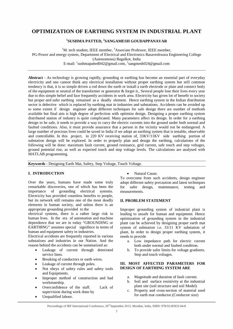
Fig.1:Design procedure block diagram
Steps for grounding design calculation: The design process of a substation grounding system requires many steps. The following steps are for the design of the ground grid: Step 1: The property map and general location plan of the substation should provide good estimates of the area to be grounded. A soil resistivity test will determine the soil resistivity profile and the soil model needed. Step 2: The conductor size is determined. The fault current 3I0 should be the maximum expected future fault current that will be conducted by any conductor in the grounding system, and the time, tc, should reflect the maximum possible clearing time (including backup). Step 3: The tolerable touch and step voltages are [to be] determined. The choice of time, ts, is based on the judgment of the design engineer. Step 4: The preliminary design should include a conductor loop surrounding the entire grounded area, plus adequate cross conductors to provide convenient access for equipment grounds, etc. The initial estimates of conductor spacing and ground rod locations should be based on the current, IG, and the area being grounded. Step 5: Estimates of the preliminary resistance of the grounding system in uniform soil can be determined. For the final design, more accurate estimates of the resistance may be desired. Computer analysis based on modeling the components of the grounding system in detail can compute the resistance with a high degree of accuracy, assuming the soil model is chosen correctly. Step 6: The current, IG, is determined. To prevent overdesign of the grounding system, only that portion of the total fault current, 3I0, that flows through the grid to remote earth should be used in designing the grid. The current, IG, should, however, reflect the worst fault type and location, the decrement factor, and any future system expansion. Step 7: If the GPR of the preliminary design is below the tolerable touch voltage, no further analysis is necessary. Only additional conductor required to provide access to equipment grounds is necessary. Step 8: The calculation of the mesh and step voltages for the grid as designed can be done by the approximate analysis techniques for uniform soil, or by the more accurate computer analysis techniques. Step 9: If the computed mesh voltage is below the tolerable touch voltage, the design may be complete (see Step 10). If the computed mesh voltage is greater
Optimization Of Earthing System In Industrial Plant
Proceedings of IRF International Conference, 26th September 2015, Mumbai, India, ISBN: 978-93-85832-04-8
9
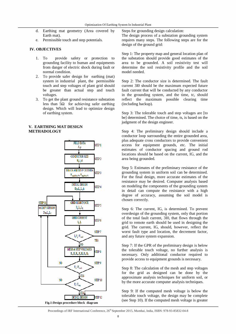
than the tolerable touch voltage, the preliminary design should be revised (see Step 11). Step 10: If both the computed touch and step voltages are below the tolerable voltages, the design needs only the refinements required to provide access to equipment grounds. If not, the preliminary design must be revised (see Step 11). Step 11: If either the step or touch tolerable limits are exceeded, revision of the grid design is required. These revisions may include smaller conductor spacing, additional ground rods, etc Step 12: After satisfying the step and touch voltage requirements, additional grid and ground rods may be required. The additional grid conductors may be required if the grid design does not include conductors near equipment to be grounded. Additional ground rods may be required at the base of surge arresters, transformer neutrals, etc. The final design should also be reviewed to eliminate hazards due to transferred potential and hazards associated with special areas of concern. The block diagram in Fig.1 illustrates the procedure to design the ground grid. Earth Mat is preferable to substations because of space saving on the ground level due to substantial reduction of earth pits which leads to ease of coordination. Earth Mat minimizes the danger of high step or touch voltages in critical operating areas or places that are frequently used by people.. Hence conventional pipe and plate earth pits are replced by earth mat . 33KV/11KV SUBSTATION OF PLANT EARTHING DESIGN CALCULATION: As per designing steps: Area and soil resistivity: As per initial design assessment the area for grounding assume as square 20m×20m grid with no ground rods area A becomes 400 m2 shown in Fig.2 average normal resistivity ρ of 40Ω-m is based on soil resistivity’s measurement by wenner’s four pin method. Conduct size: The 11KV Bus fault value 5798.69A Should be used to size the grounding conductor. the required cross sectional area of conductor in circular mils is
Fig.2:earthing mat design without rods
Crushed Rock Resistivity (Wet) in ohm meters -ݏߩCs - Surface Layer De-rating Factor OR Reduction Factor Grid resistance for Initial design :
Maximum grid current IG and GPR(Ground Potential Rise):
Mesh voltage Em:
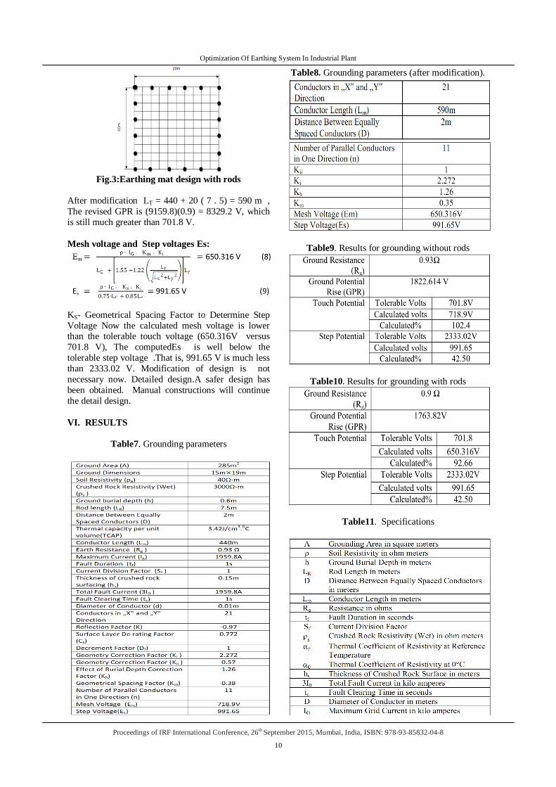
The mesh voltage is greater than that of tolerable touch voltage (i.e. 718.9 versus 701.8 ) .The grid design must be modified. The preliminary design will be modified by including 20 ground rods, each 7.5 m (24.6 ft) long, around the perimeter of the grid. As shown in Fig.3
Optimization Of Earthing System In Industrial Plant
Proceedings of IRF International Conference, 26th September 2015, Mumbai, India, ISBN: 978-93-85832-04-8
10
Fig.3:Earthing mat design with rods
After modification LT = 440 + 20 ( 7 . 5) = 590 m , The revised GPR is (9159.8)(0.9) = 8329.2 V, which is still much greater than 701.8 V. Mesh voltage and Step voltages Es:
KS- Geometrical Spacing Factor to Determine Step Voltage Now the calculated mesh voltage is lower than the tolerable touch voltage (650.316V versus 701.8 V), The computedEs is well below the tolerable step voltage .That is, 991.65 V is much less than 2333.02 V. Modification of design is not necessary now. Detailed design.A safer design has been obtained. Manual constructions will continue the detail design. VI. RESULTS
Table7. Grounding parameters
Table8. Grounding parameters (after modification).
Table9. Results for grounding without rods
Table10. Results for grounding with rods
Table11. Specifications
Optimization Of Earthing System In Industrial Plant
Proceedings of IRF International Conference, 26th September 2015, Mumbai, India, ISBN: 978-93-85832-04-8
11
CONCLUSION Conventional pipe and plate earthing pits are replaced by earth mat where earth mat is preferred for substation earthing of plant because of space saving on ground level. Modification of industrial plant earthing mat design steps and hand calculations account for optimization of earthing system where we have achieved actual step and touch voltages are
less than tolerable step and touch voltages. Soil resistivity and earth resistance has been tested and achieved as less than 1Ω for 33KV/11KV grid and small substations ,other locations of plant as 1 Ω -5 Ω.This earth resistance values are considered as best values for the plant which provides human and equipment safety. Manual calculation results of earth mat design has been analysed with MATLAB programming results which are more satisfactory results. REFERENCES
[1]. "IEEE 80-2000 IEEE Guide for Safety in AC Substation Grounding."
[2]. Lim, S.C.; Gomes, C.; Nourirad, G.; Kadir, M.Z.A.A. "Significance of localized soil resistivity in designing a grounding system", 2014 IEEE 8th International Power Engineering and Optimization Conference (PEOCO), , on page(s): 324 – 329
[3]. Mohammad Ali Adelian, “Improvement of Substation Earthing “April 2014 (IJEAT) International Journal of Engineering and Advanced Technology Volume-3, Issue-4.
[4]. M.H.Shwedi, Umar M.Johar , T. R. SHELTAMI “ Toward safe grounding to Industrial Plants Saudi Arebia case study”2009 20th International conference on electricity distribution paper 0022.Goren,
[5]. Turan“Electric Power Distribution System engineeringi.” CRC Press. 2008.