Embed Size (px)
Citation preview

Solar Energy 74 (2003) 505–511
O ptimisation of minimum backup solar water heating systema b ,*D. Mills , G.L. Morrison
aDepartment of Applied Physics, University of Sydney, Sydney, NSW 2006, AustraliabSchool of Mechanical and Manufacturing Engineering, University of New South Wales, Sydney, NSW 2052, Australia
Received 17 July 2002; accepted 2 May 2003
Abstract
Current flat plate solar water heaters overproduce slightly in summer and have poor performance in winter at the time ofmaximum load. They use an expensive absorber plate over the entire absorbing aperture of the collector and fail to use thebackside of the absorber. They often have under insulated tanks and are not optimised as integrated systems. This paperdescribes a design approach taken to use existing commercial flat plate absorber and tank components in a new way tomaximise solar contribution and minimise material usage in the construction of the system. The design criterion used is notmaximum peak efficiency, but minimum annual backup energy supplied to the system to meet an annual load. Thiscorresponds to meeting a minimum greenhouse emissions requirement in both invested pollution during manufacture andpollution from backup energy supplied. Two new designs are shown which allow the solar fraction of systems to beincreased to approximately 80–90% in Sydney Australia using a standard model of domestic hot water usage specified inAustralian Standard AS4234. Pollution from fuel use drops to as little as 40% of that of conventional flat plate solar waterheaters. These new designs use one absorber plate instead of two and a smaller and better insulated tank. Comparisons ofsolar fraction are evaluated for a range of climatic conditions. An important insight is that with such a performanceoptimised system the ultimate solar fraction is limited by occasional long duration cloud cover at the site of installation andmaking the system larger only increases dumped energy, not utilisable energy. Technical efficiency improvements onlyreduce the required collector area. However, some additional backup fuel reductions can be made through manual control ofbackup energy use, because this allows finer control of backup relative to real demand. Pollution from backup fuel usagemay be able to be reduced to 1/4 that of current flat plate solar water heaters. 2003 Elsevier Ltd. All rights reserved.
1 . Introduction limited to an annual solar fraction of about a 60–70% inthe largest potential markets such as Sydney and Brisbane.
In clear climates, the annual percentage of thermal water In earlier work (Rabl, 1976; Mills and Giutronich, 1978,heating load supplied by a solar water heater can be very 1979; Mills et al., 1994), it was suggested that collectorhigh, often in excess of 90% as an annual average. performance could be tuned using non-imaging asymmetri-However, in more temperate latitudes this figure falls cal reflector elements so that winter collection ability wasbecause of a combination of lower seasonal solar irradia- boosted to improve annual solar contribution. However,tion and lower ambient temperatures leading to higher the physical size and appearance of many such systemscollector thermal losses, and lower input water tempera- constitutes a significant market barrier. Furthermore, thesetures in winter. For example, a typical flat plate collector systems can overheat significantly under certain condi-system in the relatively good Eastern Australian climate is tions.
This paper describes a design approach taken to userelatively inexpensive commercial flat plate elements in anew way to maximise solar contribution and minimise*Corresponding author. Tel.:161-2-9385-4127; fax:161-2-material usage in the construction of the system. The9663-1222.design criterion used is not maximum peak efficiency, butE-mail addresses: [email protected](D. Mills),
[email protected](G.L. Morrison). minimum annual backup energy supplied to the system to
0038-092X/03/$ – see front matter 2003 Elsevier Ltd. All rights reserved.doi:10.1016/S0038-092X(03)00191-9
506 D. Mills, G.L. Morrison / Solar Energy 74 (2003) 505–511
meet an annual load. This corresponds to meeting a insulation on the upper face. Transparent insulation isminimum greenhouse emissions requirement in both in- possibly not justified in such a low temperature device,vested pollution during manufacture and pollution from particularly as most transparent insulation material melts atbackup energy supplied. The evaluation of the design temperatures well below the stagnation temperature of thischanges made during optimisation is carried out using a type of collector. More recently,Kothdiwala et al. (1996)standard model of domestic hot water usage specified in have proposed designs incorporating seasonal load match-Australian Standard AS4234 (1994). This paper is ing but they are very bulky and would be difficult toconcerned with a practical collector development pro- market.gramme by an Australian manufacturer, and the concerns In addressing the depth of the panel required to fit theof the manufacturer with regard to aesthetic issues have reflector under the absorber plate it became clear that, in ahad a significant effect on the outcome of the design. conventional flat plate thermosyphon system with an
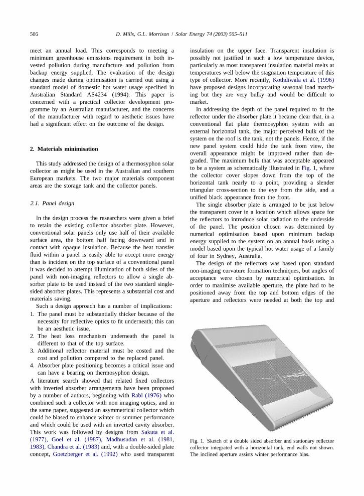
external horizontal tank, the major perceived bulk of thesystem on the roof is the tank, not the panels. Hence, if thenew panel system could hide the tank from view, the2 . Materials minimisationoverall appearance might be improved rather than de-graded. The maximum bulk that was acceptable appearedThis study addressed the design of a thermosyphon solarto be a system as schematically illustrated inFig. 1, wherecollector as might be used in the Australian and southernthe collector cover slopes down from the top of theEuropean markets. The two major materials componenthorizontal tank nearly to a point, providing a slenderareas are the storage tank and the collector panels.triangular cross-section to the eye from the side, and aunified black appearance from the front.
2 .1. Panel design The single absorber plate is arranged to be just belowthe transparent cover in a location which allows space for
In the design process the researchers were given a brief the reflectors to introduce solar radiation to the undersideto retain the existing collector absorber plate. However, of the panel. The position chosen was determined byconventional solar panels only use half of their available numerical optimisation based upon minimum backupsurface area, the bottom half facing downward and in energy supplied to the system on an annual basis using acontact with opaque insulation. Because the heat transfer model based upon the typical hot water usage of a familyfluid within a panel is easily able to accept more energy of four in Sydney, Australia.than is incident on the top surface of a conventional panel The design of the reflectors was based upon standardit was decided to attempt illumination of both sides of the non-imaging curvature formation techniques, but angles ofpanel with non-imaging reflectors to allow a single ab- acceptance were chosen by numerical optimisation. Insorber plate to be used instead of the two standard single- order to maximise available aperture, the plate had to besided absorber plates. This represents a substantial cost andpositioned away from the top and bottom edges of thematerials saving. aperture and reflectors were needed at both the top and
Such a design approach has a number of implications:1. The panel must be substantially thicker because of the
necessity for reflective optics to fit underneath; this can
be an aesthetic issue.2. The heat loss mechanism underneath the panel is
different to that of the top surface.3. Additional reflector material must be costed and the
cost and pollution compared to the replaced panel.4. Absorber plate positioning becomes a critical issue and
can have a bearing on thermosyphon design.A literature search showed that related fixed collectorswith inverted absorber arrangements have been proposedby a number of authors, beginning withRabl (1976)whocombined such a collector with non imaging optics, and inthe same paper, suggested an asymmetrical collector whichcould be biased to enhance winter or summer performanceand which could be used with an inverted cavity absorber.This work was followed by designs fromSakuta et al.(1977), Goel et al. (1987), Madhusudan et al. (1981, Fig. 1. Sketch of a double sided absorber and stationary reflector1983), Chandra et al. (1983)and, with a double-sided plate collector integrated with a horizontal tank, end walls not shown.concept,Goetzberger et al. (1992)who used transparent The inclined aperture assists winter performance bias.
D. Mills, G.L. Morrison / Solar Energy 74 (2003) 505–511 507
convection loss which could be stabilised by a thin PTFEfilm across AC.
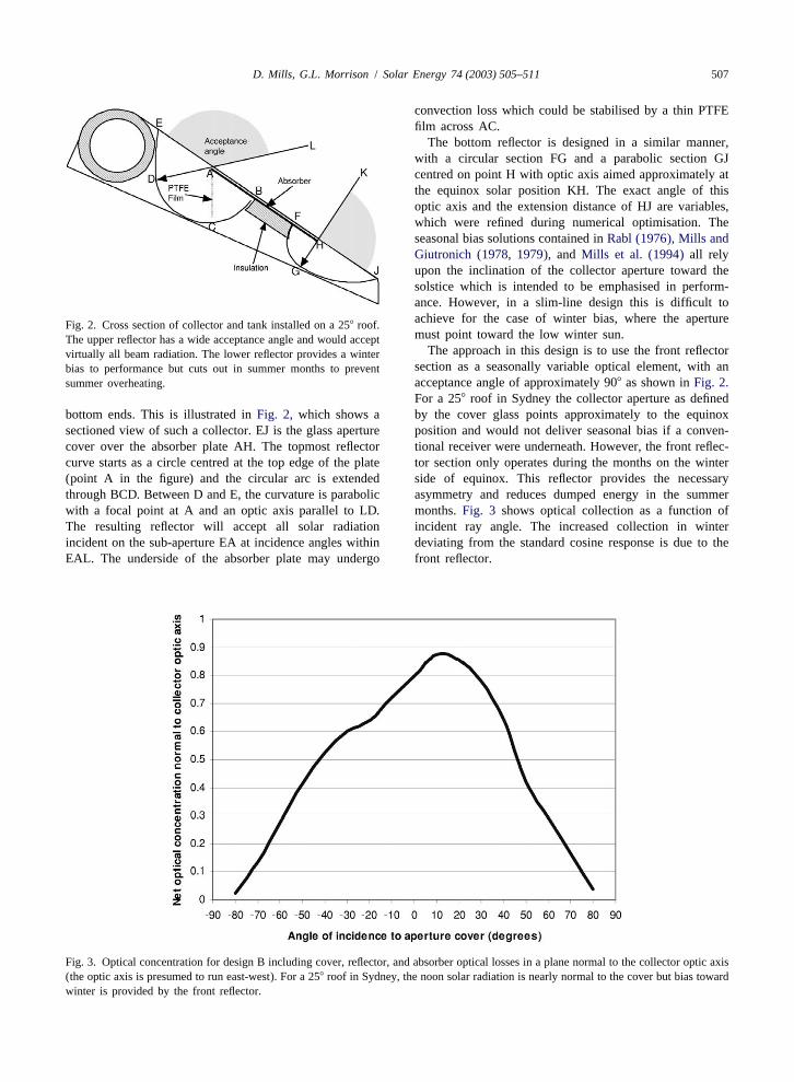
The bottom reflector is designed in a similar manner,with a circular section FG and a parabolic section GJcentred on point H with optic axis aimed approximately atthe equinox solar position KH. The exact angle of thisoptic axis and the extension distance of HJ are variables,which were refined during numerical optimisation. Theseasonal bias solutions contained inRabl (1976), Mills andGiutronich (1978, 1979),and Mills et al. (1994)all relyupon the inclination of the collector aperture toward thesolstice which is intended to be emphasised in perform-ance. However, in a slim-line design this is difficult toachieve for the case of winter bias, where the apertureFig. 2. Cross section of collector and tank installed on a 258 roof.must point toward the low winter sun.The upper reflector has a wide acceptance angle and would accept
The approach in this design is to use the front reflectorvirtually all beam radiation. The lower reflector provides a wintersection as a seasonally variable optical element, with anbias to performance but cuts out in summer months to preventacceptance angle of approximately 908 as shown inFig. 2.summer overheating.For a 258 roof in Sydney the collector aperture as defined
bottom ends. This is illustrated inFig. 2, which shows a by the cover glass points approximately to the equinoxsectioned view of such a collector. EJ is the glass aperture position and would not deliver seasonal bias if a conven-cover over the absorber plate AH. The topmost reflector tional receiver were underneath. However, the front reflec-curve starts as a circle centred at the top edge of the plate tor section only operates during the months on the winter(point A in the figure) and the circular arc is extended side of equinox. This reflector provides the necessarythrough BCD. Between D and E, the curvature is parabolic asymmetry and reduces dumped energy in the summerwith a focal point at A and an optic axis parallel to LD. months.Fig. 3 shows optical collection as a function ofThe resulting reflector will accept all solar radiation incident ray angle. The increased collection in winterincident on the sub-aperture EA at incidence angles within deviating from the standard cosine response is due to theEAL. The underside of the absorber plate may undergo front reflector.
Fig. 3. Optical concentration for design B including cover, reflector, and absorber optical losses in a plane normal to the collector optic axis(the optic axis is presumed to run east-west). For a 258 roof in Sydney, the noon solar radiation is nearly normal to the cover but bias towardwinter is provided by the front reflector.

508 D. Mills, G.L. Morrison / Solar Energy 74 (2003) 505–511
2 .2. Absorber plate radiation and thermal model developed in TRNSYS (Kleinet al., 1999). The overall heat loss coefficient for the
2double-sided plate was computed to be 2.6 W/m K.The standard absorber plate is selectively surfaced onRecent measurements of the first prototype without theboth sides, mounted parallel to the cover glass about 2 cmconvection suppression film (Groenhout et al., 2001) havebelow it, and sealed around the edges to the cover.shown that the heat loss coefficient ranges from 2.0 W/Importantly, the reflector absorber system forms two
2 2m K at low temperature differences to 3.3 W/m K for athermal cavities underneath the absorber and relativelyplate to ambient temperature difference of 50 K. The heatstagnant air in these cavities results in low heat loss. A thinloss may be reduced when the convection film is added toPTFE barrier is used to segment the upper cavity as shownthe top cavity.in Fig. 2 to reduce convection from the underside of the
Initial runs were performed on several variants of theupper cavity, simulating the performance of a horizontalcollector having a varied aperture angle on a 258 roof usingcavity receiver. There was not enough space in the designSydney solar radiation data (Morrison and Litvak, 1988).to fully utilise all of the absorber plate under surface, so
After work with simpler models which allowed consi-the remainder was insulated as shown inFig. 2. The netderable optimisation to be done, a study of annual per-result is a considerably reduced overall thermal lossformance was carried out with a system that incorporated acompared to conventional single sided absorber platetank of 220 l insulated to a level that:designs. The reductions of heat loss outweigh increased1. Would achieve the same energy delivery as a standardoptical loss caused by using reflectors. The single plate
300 l tank by operating at a higher temperaturedesign offers savings not only in plate manufacture but in2. Achieve a reduction of 50% in the UA of the standardreduced connection fitting costs and labour.
300 l tank as a result of improved insulation.2 .3. Storage tank The best two of these are the designs A and B shown in
outline in Fig. 4, where they are compared to a standardThe tank was redesigned to match the characteristics of flat plate close-coupled thermosyphon design in profile.
the collector, which include an ability to operate at higher Design A uses a slightly narrower acceptance angletemperature with lower loss than a conventional single- (122.58) for the upper reflector than design B (1258),sided two-plate design. This drives the design toward a which allows a longer reflector and an increased uppersmaller tank with higher water temperatures than normal reflector aperture size. The plate in design A has lowerbut limited to 908C before dumping. Water at high inclination, allowing an increase in total aperture down thetemperature will be mixed with cold water in a mixingvalve before use. The higher storage temperature requires
increased tank insulation thickness but the overall diameterof the tank is almost unchanged. The material usage of thetank is substantially reduced with the tank volume being220 l instead of the normal 300–400 l. This reduces costand greenhouse emissions invested during construction.
3 . Results of modelling optimisation
A raytrace model was used to generate optical con-centration maps in terms of transverse and longitudinalincidence angles. A two-dimensional model was used togenerate concentration data for a series of slices throughthe array. These were assembled to generate three-dimen-sional maps of the optics of the systems. The assumedmirror reflectance was 0.95, typical of very thin glassreflector. The cover glass was assumed to have refractiveindex of 1.5, a thickness of 3.2 mm, and to have negligibleabsorption. Thin PTFE film is used to contain thermalpockets underneath the plate. The normal absorptance ofthe selective coating was assumed to be 0.93 when theraytrace work was performed (this is now closer to 0.95for currently available chrome black and sputtered sur-faces). Fig. 4. Relative size of modelled collectors. All have the same
The three dimensional maps were used as inputs to a width.

D. Mills, G.L. Morrison / Solar Energy 74 (2003) 505–511 509
roof. Design A achieves a backup requirement of 2.42 orientations from north to west (for a 258 roof inclination).GJ/year for a useful delivered energy load of 12.5 GJ/year The system configuration evaluated was the B seriesusing a conventionally insulated 220 l tank. This is the design operating in Sydney with a thermostat set tempera-larger of the two designs and the less elegant. The larger ture of 608C, user control of boosting and a 220-l tankaperture area in this model is required to offset the higher with reduced heat loss (50% of current tank UA). Thetank heat loss. performance variation with roof slope is shown inFig. 5.
Design B is designed to be used with a tank with heat These results indicate that the performance is not sig-losses 50% below current practice. It is more pleasing in nificantly influenced by roof slope. The minimum auxiliaryprofile than design A and is no larger in aperture than a use occurs for a roof slope of 258, which is the designconventional two-plate single-sided absorber system. Bac- point. The variation of annual performance with roofkup energy for design B is calculated to be to 3.08GJ/year orientation is shown inFig. 6. The results indicate that thewhen using a standard 220 l tank, but this drops to 2.73 performance is not significantly affected for orientationGJ/year when using a better insulated tank. In contrast, the within 458 of north, however, there is a significant drop ofA design backup energy hardly changes when used with performance for west (or east) orientations.the improved tank because the load is already satisfied in The position of the plate in the system is such thatnon-cloudy periods. conventional thermosyphon arrangements would have sig-
Table 1summarises the performance of these systems as nificant reverse thermosyphon loss at night because themodelled for Sydney, and this is compared to a conven- plate is very high for some roof angles. However, thetional two panel thermosyphon system. It is clear that authors have devised a modification, which has been testedcomparatively low levels of backup energy and pollution by the manufacturer that allows daytime thermosyphonare achievable. circulation to occur effectively without excessive night-
Another important aspect of the new designs is that such time reverse circulation. This will be reported in a laterlow backup requirements would allow manual backup paper.control operation with high customer satisfaction. Using asimulation of manual backup user control, the compact B 3 .2. Performance of B design in different locationsdesign achieved a very low auxiliary consumption of 1.69GJ/year in Sydney. Use of the highly insulated tank only The performance of the B design with improved tankreduces the B system annual auxiliary consumption to 1.5 insulation (50% of current heat loss) and a thermostat setGJ/year because it is unable to supply much more temperature of 608C was evaluated for a series of loca-additional useful energy to the load as backup is almost tions in Australia, USA, Japan and Italy. The annualexclusively due to long periods of poor weather. The high energy savings for each location are shown inTable 2.Insolar fraction suggests that the units can be left with the Darwin the performance was excellent; however, the waterbackup off for extended periods in Sydney except for the temperature was above 858C for 5 months. Perth had highMay–June period. temperatures during January–March and Rome had exces-
Both the A and B designs would achieve 85–90% solar sive temperatures during June–September. To limit thesecontribution in Sydney under automatic backup without the high temperature conditions a delivery water mixing valveuse of exotic technology. is necessary.
Thermal performance of a prototype system is reported3 .1. Effect of roof inclination and orientation in a companion paper (Groenhout et al., 2001). Losses
have recently been determined with and without convec-The performance of the B series design was evaluated tion suppression PTFE curtains and are similar to the
for a range of roof slopes from 15 to 358 and roof design values used in this study.
T able 1Annual performance of alternative systems in Sydney, Australia
Model A Model B Model B STD System220 l tank 220 l tank 220 l tank 300 l tankStd insulation Std insulation High insulation
Load (GJ/year) 12.5 12.5 12.5 12.5Collector input (GJ/year) 12.6 11.6 11.6 11.1Tank loss (GJ/year) 2.32 2.13 1.78 4.0Auxiliary (GJ/year) 2.42 3.08 2.73 6.1Dumped energy (GJ/year) 0.15 0.08 0.08 0.0
aRelative pollution 0.40 0.50 0.45 1.00a Compared to a conventional solar water heater.

510 D. Mills, G.L. Morrison / Solar Energy 74 (2003) 505–511
Fig. 5. Variation of auxiliary energy as a function of the collector slope.
4 . Conclusions This study illustrates that it is possible to design a solarwater heater using standard absorber plates and com-
Current flat plate solar water heaters overproduce slight- ponents which uses approximately 1/2 the backup energyly in summer and have poor performance in winter at the of existing systems, and also uses less material in manufac-time of maximum load. They use an expensive absorber ture. The visual appearance of such designs would be anplate over the entire absorbing aperture of the collector and improvement over the current unintegrated ‘plates1tank’fail to use the backside of the absorber. They often have appearance of thermosyphon systems with external tanks.under insulated tanks and are not optimised as integrated An important insight from the optimisation criterionsystems. used in this paper is that a collector optimised for
Fig. 6. Variation of auxiliary energy use as a function of collector orientation.

D. Mills, G.L. Morrison / Solar Energy 74 (2003) 505–511 511
T able 2 R eferencesAnnual energy savings for 2000B system, 220 l tank with low heatloss, set temperature560 8C, roof slope5258, facing the equator C handra, R., Goel, V., Raychaudhuri, B., 1983. Performance
comparison of two-pass modified reverse flat-plate collectorLocation Annual energywith conventional flat-plate collectors. Energy Convers. Manag.savings (%)3 (3), 177–184.
Sydney 85 G oel, V., Chandra, R., Raychaudhuri, B., 1987. A study per-Perth 87 formance of the reverse flat-plate collector. Energy Convers.Brisbane 87 Manag. 27 (4), 335–341.Darwin 94 G oetzberger, A. et al., 1992. A transparently insulated bifaciallyMelbourne 72 irradiated solar flat plate collector. Solar Energy 49 (5), 403.Kumamoto 76
G roenhout, N., Morrison, G.L., Behnia, M., 2001. Design of anMiami 86
advanced bifacial solar collector. In: Proceedings of the ISESRome 82
Annual Conference Adelaide.K lein, S.A. et al., 1999. TRNSYS. A Transient System Simula-
tion. University of Wisconsin, Madison.K othdiwala, A.F., Eames, P.C., Norton, B., 1996. Optical per-
formance of an asymmetric inverted absorber compoundminimum backup energy is ultimately limited in annualparabolic concentrating solar collector. In: Proceedings of thesolar fraction by periods of extended cloud under which noWorld Renewable Energy Conference, pp. 562–567.collector can deliver useful energy. Increasing the size of
M adhusudan, M., Tiwari, G., Hrishikeshan, D., Sehgal, H., 1981.the optimised collector results in no significant improve-Optimization of heat losses in normal and reverse flat-platement in solar fraction; it merely increases dumped energy.configurations: analysis and performance. Energy Convers.
Improvements to selective coatings or mirror reflectanceManag. 21 (3), 191–198.
will allow a reduction in size of a collector for a given M adhusudan, M., Tiwari, G., Sehgal, H., 1983. Transient per-solar fraction, but not an increase in solar fraction. formance of normal / reverse flat-plate collector with selective
Solar contributions greater than 85% may be achieved absorber surface. Energy Convers. Manag. 23 (2), 107–111.by leaving boosting normally off and manually boosting M ills, D.R., Monger, A., Morrison, G.L., 1994. Comparison ofonly when necessary. This approach can be facilitated by symmetrical and asymmetrical reflectors for evacuated tube
solar receivers. Solar Energy 53 (1), 91–104.having a manual backup control switch easily available,M ills, D.R., Giutronich, J.E., 1979. Symmetrical and asymmetricalwhich allows rapid heat up of a small top section of the
ideal cylindrical radiation transformers and concentrators. J.tank and automatically resets to solar only mode. PollutionOpt. Soc. Am. 62 (2), 325–328.may be able to be reduced to about 1/4 that of convention-
M ills, D.R., Giutronich, J.E., 1978. Asymmetrical non-imagingal solar systems with this measure.cylindrical solar collectors. Solar Energy 20, 1.
M orrison, G.L, Litvak, A., 1988. Condensed solar radiation database for Australia. Mechanical Engineering, University of New
A cknowledgements South Wales, FMT/1.S akuta, K. et al., 1977. Fundamental characteristics of the reverse
The authors wish to thank the Australian Research flat plate collector. Energy Dev. Jpn. 1 (3), 265–275, OriginallyCouncil, Solahart Industries, and the University of Sydney published in the Proceedings of the 3rd Technical Meetings of
Japan Solar Energy Society, vol. 3 (in Japanese)).Science Foundation for Physics for assistance in this work.