Embed Size (px)
Citation preview

General rights Copyright and moral rights for the publications made accessible in the public portal are retained by the authors and/or other copyright owners and it is a condition of accessing publications that users recognise and abide by the legal requirements associated with these rights.
Users may download and print one copy of any publication from the public portal for the purpose of private study or research.
You may not further distribute the material or use it for any profit-making activity or commercial gain
You may freely distribute the URL identifying the publication in the public portal If you believe that this document breaches copyright please contact us providing details, and we will remove access to the work immediately and investigate your claim.
Downloaded from orbit.dtu.dk on: Mar 15, 2020
Optimal Design of DC Fast-Charging Stations for EVs in Low Voltage Grids
Gjelaj, Marjan; Træholt, Chresten; Hashemi Toghroljerdi, Seyedmostafa; Andersen, Peter Bach
Published in:Proceedings of 2017 IEEE Transportation Electrification Conference
Link to article, DOI:10.1109/ITEC.2017.7993352
Publication date:2017
Document VersionPeer reviewed version
Link back to DTU Orbit
Citation (APA):Gjelaj, M., Træholt, C., Hashemi Toghroljerdi, S., & Andersen, P. B. (2017). Optimal Design of DC Fast-Charging Stations for EVs in Low Voltage Grids. In Proceedings of 2017 IEEE Transportation ElectrificationConference (pp. 684-689). IEEE. https://doi.org/10.1109/ITEC.2017.7993352

Optimal Design of DC Fast-Charging Stations for
EVs in Low Voltage Grids
Marjan Gjelaj, Chresten Træholt, Seyedmostafa Hashemi, Peter Bach Andersen
EVLabDK-CEE Department of Electrical Engineering
Technical University of Denmark - Copenhagen, Denmark
Email: [email protected], [email protected], [email protected], [email protected]
Abstract— DC Fast Charging Station (DCFCS) is essential for
widespread use of Electric Vehicle (EVs). It can recharge EVs in
direct current in a short period of time. In recent years, the
increasing penetration of EVs and their charging systems are
going through a series of changes. This paper addresses the design
of a new DCFCS for EVs coupled with a local Battery Energy
Storage (BES). DCFCS is equipped with a bidirectional AC/DC
converter for feeding power back to the grid, two lithium batteries
and a DC/DC converter. This paper proposes an optimal size of
the BES to reduce the negative impacts on the power grid through
the application of electrical storage systems within the DC fast
charging stations. The proposed solution decreases the charging
time and the impact on the low voltage (LV) grid significantly. The
charger can be used as a multifunctional grid-utility such as
congestion management and load levelling. Finally, an optimal
design of the DCFSC has been done to evaluate the feasibility and
the operability of the system in different EVs load conditions.
Keywords— DC fast charging station, battery energy storage,
electric vehicle.
I. INTRODUCTION
European cities are increasing driving restrictions on gasoline vehicles and replacing them with electric vehicles (EVs) as a responsible alternative to reduce the CO2 emotions. Many factors are contributing to the spread of electric transportation, and the sector is starting to benefit from incentives given by individual governments and European Commission [1]. Considering the growing number of EVs, it seems necessary to establish a smart DC fast charging infrastructure to provide their required energy demand in a short period of time. The EN /IEC 61851 and automotive engineers in U.S. SAE J1772 have proposed their standards on the charging modes for EVs and the maximum current delivered in DC [2]. According to the international standards, there are different charging modes classified as mode 1, 2, 3 and 4 for the EV conductive charging system. IEC 61851 applies to on-board and off-board equipment for charging electric vehicles and providing electrical power for any additional services on the vehicle if required when connected to the electrical grid. One method for EV charging is to connect the AC supply network to an on-board charger, the power delivered is between 7 kW and 43kW [3]. The charging rate requires about 2-3 hours to store the energy needed to cover 150km. Another method to recharge EVs is to use an off-board charger for delivering direct current, to recharging in a short period of time. In addition the charging
facilities operating at high power levels. Currently, the delivered power in DC is between 50 kW and 120 kW for public charging stations with a charging rate about 45 min and 30 min to store energy for 150km of driving. The fast charging station has met implementation difficulties in the major European cities, because its progress poses demanding requirements in terms of EV battery and charging rate restrictions. In addition, there are many issues related to the impact of the DC fast charging on the distribution network in the low voltage (LV), such as control the congestion during the peak hours and the high losses among the feeders [4]. The widespread use of EVs and especially the installations of the fast charger requires investigating on the distribution grid impact. So far, many studies have been done about the EVs and their grid impact. To address this issue, research is moving in various directions, for example in some papers, a coordinated charging system is proposed to minimize the power losses and maximize the main grid load force for an optimal charging profile for EVs and plug-in hybrid electric vehicles (PHEVs) [5]. To mitigate the congestion form EVs, other studies have proposed dynamic price for the uses to keep the reliability of the electrical grid [6]. N.G. Paterakis has developed a detailed energy management system structured for unpredictable load such as EVs and PHEVs. He has determined the optimal day-ahead appliance scheduling of a smart-load based hourly pricing and peak power limiting based on a demand response strategies [7]. Other authors have focused their studies on the impact of the charging stations based on simulation models. The models determine the spatial distribution of different charging stations to evaluate the potential for load shifting EVs demand [8]. Although the DC fast charging station has a deep impact on the grid and at the moment few researcher are working to determine the fast charging stations’ demand. It is very important to design an appropriate fast charging station for EVs, which is able to meet the expected demand. Designing an appropriate charging station in LV grid requires not only meeting the charging demand at any time of the day, but also minimizing the station operation costs [9]. Especially, in LV grid where the operators are focused to minimized the losses and to reduce the size of the electrical lines and avoid the network congestion. The load curve profile of the DC fast-charging station can increases significantly the peak load demand as well as high connection fees to grid operators in order to offset the cost of larger transformers and electrical equipment. Some recent studies have focused on using battery energy storage as a buffer between the grid and the charging stations in
order to reduce their peak consumption [10], but more work is required on the optimal size of BES in the station. In this paper, the authors attempt to determine the optimal design of the DC fast charging station to reduce their grids impact. In particular, we propose a new design of a stationary battery energy system that physically decouples a DC fast charging from an LV distribution. The rest of the manuscript is organized as follows. In Section II conductive charging modes and in the Section III charging station design and demand modelling. Section IV the description of the optimal design of the BES is given in Section IV and V, respectively with the simulation results. Finally, in Section VI the conclusions with the optimal size of the BES within the DC fast-charging stations and its practical implementation in LV grids.
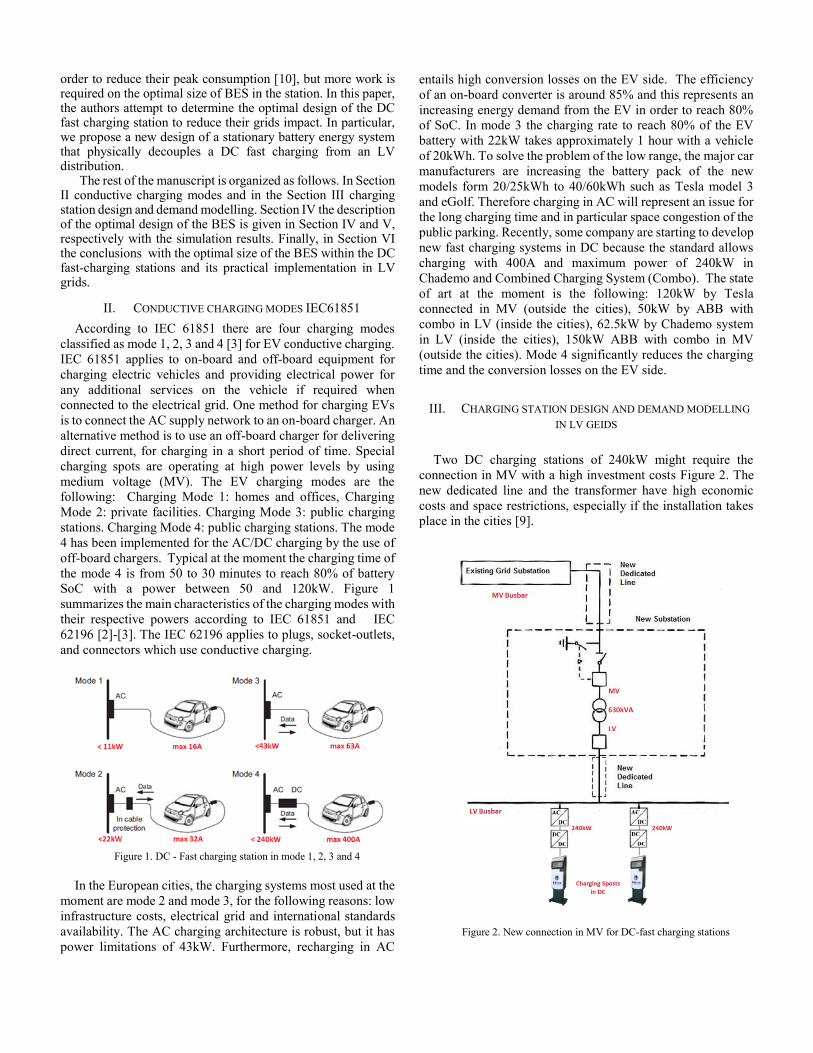
II. CONDUCTIVE CHARGING MODES IEC61851
According to IEC 61851 there are four charging modes
classified as mode 1, 2, 3 and 4 [3] for EV conductive charging.
IEC 61851 applies to on-board and off-board equipment for
charging electric vehicles and providing electrical power for
any additional services on the vehicle if required when
connected to the electrical grid. One method for charging EVs
is to connect the AC supply network to an on-board charger. An
alternative method is to use an off-board charger for delivering
direct current, for charging in a short period of time. Special
charging spots are operating at high power levels by using
medium voltage (MV). The EV charging modes are the
following: Charging Mode 1: homes and offices, Charging
Mode 2: private facilities. Charging Mode 3: public charging
stations. Charging Mode 4: public charging stations. The mode
4 has been implemented for the AC/DC charging by the use of
off-board chargers. Typical at the moment the charging time of
the mode 4 is from 50 to 30 minutes to reach 80% of battery
SoC with a power between 50 and 120kW. Figure 1
summarizes the main characteristics of the charging modes with
their respective powers according to IEC 61851 and IEC
62196 [2]-[3]. The IEC 62196 applies to plugs, socket-outlets,
and connectors which use conductive charging.
Figure 1. DC - Fast charging station in mode 1, 2, 3 and 4
In the European cities, the charging systems most used at the
moment are mode 2 and mode 3, for the following reasons: low
infrastructure costs, electrical grid and international standards
availability. The AC charging architecture is robust, but it has
power limitations of 43kW. Furthermore, recharging in AC
entails high conversion losses on the EV side. The efficiency
of an on-board converter is around 85% and this represents an
increasing energy demand from the EV in order to reach 80%
of SoC. In mode 3 the charging rate to reach 80% of the EV
battery with 22kW takes approximately 1 hour with a vehicle
of 20kWh. To solve the problem of the low range, the major car
manufacturers are increasing the battery pack of the new
models form 20/25kWh to 40/60kWh such as Tesla model 3
and eGolf. Therefore charging in AC will represent an issue for
the long charging time and in particular space congestion of the
public parking. Recently, some company are starting to develop
new fast charging systems in DC because the standard allows
charging with 400A and maximum power of 240kW in
Chademo and Combined Charging System (Combo). The state
of art at the moment is the following: 120kW by Tesla
connected in MV (outside the cities), 50kW by ABB with
combo in LV (inside the cities), 62.5kW by Chademo system
in LV (inside the cities), 150kW ABB with combo in MV
(outside the cities). Mode 4 significantly reduces the charging
time and the conversion losses on the EV side.
III. CHARGING STATION DESIGN AND DEMAND MODELLING
IN LV GEIDS
Two DC charging stations of 240kW might require the
connection in MV with a high investment costs Figure 2. The
new dedicated line and the transformer have high economic
costs and space restrictions, especially if the installation takes
place in the cities [9].
Figure 2. New connection in MV for DC-fast charging stations

The DCFCS in combination with the BES can represent a
reliable solution to avoid the connection in MV especially
within residential areas. The annual cost reduction of BEVs has
been estimated around 8% [11]-[12]. This represents a chance
to evaluate possible scenarios of the DCFCS in order to develop
a smart charging station and control methods for these flexible
loads [13].
In addition, DCFCS with the BESs gives the opportunity to
the users to recharge the EVs up to 80% of their SOC with
charging rate of 9 -10 minutes. The new design of the charging
stations is based on the installation of two identical battery
energy system (BES1 and BES2) that physically decouples a
DC fast charging station (DCFCS) from an LV distribution
grid, as shown in Figure 4.
Figure 3. DC fast charging station in mode 4 without BES
Figure 4. DC fast charging station in mode 4 with BESs
The operation of such a system is based on successive
switches of the BES connections that allow one of the batteries
(BES2) to be charged from the grid while the other (BES1) is
charging an EV, as shown in Figure 5.
Figure 5. DC fast charging station in LV grids with BESs
IV. OPTIMAL DESIGN OF BESS IN FUNCTION OF CHARGING
DEMAND
The charging station will have one or more charging slots,
and each of them can be connected in the LV grid with a
minimum power of 100kW required form the grid in AC. Every
EV has a nominal capacity given by the manufacturers that
represents an amount of kilometres that the car can reach with
specific driving conditions. According to the tests performed
in the EV laboratory, only 90% of the nominal capacity is used
as work capacity. To make the EV demand study more realistic,
the following steps are made: SoC of the EV battery is fixed at
25% SoC (worst case). The EVs load demand capacity is
between: 7.2 kWh and 36kW, Table 1:
TABLE I. COMPARISON OF DIFFERENT COMMERCIAL EVS
Models
(2015-
2017)
Range
[km]
Battery
[kWh]
Usable
battery
[kWh]
SoC
25%
[kWh]
SoC
80%
[kWh]
∆
load
[kWh]
Mitsbuishi i-MiEV 100 16 14.4 3.6 10.8 7.2 Smart
Electric 110 17 15.3 3.8 11.5 7.7 Chevy
Spark EV 130 20 18 4.5 13.5 9 BMW
i3 130 22 19.8 4.95 14.9 10 Ford
Focus EV 130 23 20.7 5.17 15.5 10.33 Fiat
500e 140 24 21.6 5.4 16.2 10.8 Leaf
24kWh 130 24 21.6 5.4 16.2 10.8 Leaf
30kWh 165 30 27 6.75 20.3 13.55 Kia Soul
EV 150 30 27 6.75 20.3 13.55 Mercedes
BClassEV 170 36 32.4 8.1 24.3 16.2 VW
eGolf 300 37 33.3 8.3 25 16.7 Tesla
S 60 340 60 54 13.5 40.5 27 Tesla
model 3 350 60 54 13.5 40.5 27 Tesla
modelS80 450 80 72 18 54 36
The following statistical calculations are carried out to
evaluate EVs load demand in different confidence intervals (2):
Sample mean: ___
1
1 n
n i
i
X Xn
= 15.42kWh, with n=14
Sample variance: ___
2 2
1
1( )
1
n
nn i
i
s X Xn
(1)
14___ ___2 2 2
14
1 1
1 1( ) ( ) 107.65
1 14 1
n
nn i i
i i
s X X X Xn
and
107.75 10.375s
The confidence interval is 0.95 of BES ∈ X, with n=14, the
confidence interval is:
BES ___ ___
14 14(1 ) (1 )
2 2
( 1), ( 1)s s
X t n X t nn n
(2)
The estimation of the BES size is calculated with this expression
and student's t distribution (3):
2
( 1)/2
( 1)(
2( )
( / 2) (1 )
t
n
n
F tx
n nn
(3)
1 - α =0.95,
α = 0.05, t t (1 )2
= 13(0.975) 2.16t
BES ___ ___
14 14(1 ) (1 )
2 2
( 1), ( 1)s s
X t n X t nn n
BES ___ ___10.375 10.375
15.42 2.16,15.42 2.1615 15
9.634,21.2 kWh
If the confidence interval is 0.99 of BES ∈ X with n=14, the
confidence interval is (4):
BES ___ ___10.375 10.375
15.42 3.012,15.42 3.01215 15
(4)
7.35,23.5 kWh
In this case study there are two criteria to size the BESs:
Fist, considering EVs SoC at 80% and to cover 78% of the EVs
demand and the BES should be sized around 23.5kWh.
Second, it is important to take into account the number of
kilometers needed for driving in the city instead of their SoC at
80%, moreover the DCFCS is designed to be installed in the
cities. Table 2 shows the results of different BES and the energy
in terms of kilometers provided by the BES. The driving
efficiency of the new EVs model between 2020 and 2025 will
be around 0.1kWh/km.
TABLE II. OPTIMAL SIZE OF THE BES IN FUNCTION OF EVS SOC
SATISFACTION
BES
[kWh]
[%] of
EVs
charged
up to 80%
[%] of
EVs
charged
up to 70%
Average
[km] with
0.1
kWh/km
Average
[km] of
EVs with
SoC 25%
Total
[km]
23.5 78% 93% 235 45 280
21.5 78% 93% 215 45 260
19.5 78% 78% 195 45 240
17.5 78% 78% 175 45 220
16 78% 78% 160 45 205
15.5 75% 78% 155 45 200
15 65% 78% 150 45 195
13.5 50% 78% 135 45 180
11.5 50% 64% 115 45 160
9.5 22% 50% 95 45 140
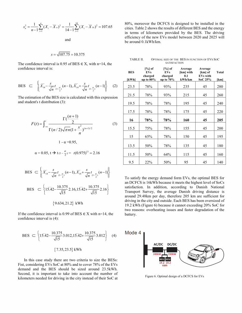
To satisfy the energy demand form EVs, the optimal BES for
an DCFCS is 16kWh because it meets the highest level of SoCs
satisfaction. In addition, according to Danish National
Transport Survey, the average Danish driving distance is
around 29.48km per day, therefore 205 km are sufficient for
driving in the city and outside. Each BES has been oversized of
19.2 kWh (Figure 6) because it cannot exceeding 20% SoC for
two reasons: overheating issues and faster degradation of the
battery.
Figure 6. Optimal design of a DCFCS for EVs

The case study uses an AD/DC converter of 100kW and charging rate of 6C (9.7min). The discharging rate through the DC/DC is 9C (6.7min) with a converter of 150kW.
V. SIMULATION RESULTS
The reliability of the system and the performance of the
DCFCS are evaluated by a 11-minute simulation in Matlab/ Simulink. A boost converter controls the DC/DC converter through the PI controllers. The boost converter helps to keep the voltage limits constant to ensure the stability of the system for each SoC of the EVs.
A. The charging process of the BESs
When the BES2 is charging an EV at 9C, the BES1, if previously discharged, can be recharged through the grid with the AC/DC converter at 100kW and a charging rate of 6C as shown in Figure 5.
Figure 7. Active power delivered by the LV grid
B. The charging process of an EV
The graph in Figure 6 shows the charging process of an EV through BES2 and the power absorbed by the electric vehicle. As previously mentioned, the DCFCS has been designed to be used in LV grids, mainly in the cities. It can recharge each vehicle up to 80% of their SoC in a time period of between 6 minutes and 7 minutes, depending on the SoC of each EV. The functionality of the charging system has been evaluated on a large scale by comparing different commercial EVs with different batteries. The case studies take into account several models from 2015 to 2017 with battery pack between 16 kWh and 80 kWh. As shown in table 1 below. All the EVs could be
charged by the DCFCS with 150 kW through the BESs. The results associated with the capability of the DCFCS and its limits in order to supply energy to the end users is shown in Figure 5.
Figure 8. Active power absorbed by the EV
C. Capability of the DCFCS
Figure 9 represents the charging limit of the DCFCS and the capability to recharge EVs up to 80% in function of their SoCs and battery packs. The DCFCS can provide to recharge EVs at 80% of SoC with maximum EVs battery pack of 40kWh. For large EVs battery pack such as Tesla models of 60/80kWh,EV-Van and EV-suv, the DCFCS can recharger them fast up to 50/60% their SoC with more then 250km of driving. If the users need more driving kilometers or they want to reach 80% of the SoC with 450 - 500km the EVs could be recharge twice with a charging time around 20min.
Figure 9. Charging limit of the DCFCS with EVs at 25% SoC
0
20
40
60
80
100
0 10 20 30 40 50 60 70 80 90
SoC
[%
]
kWh EVs

VI. CONCLUSIONS
This paper introduced an optimal size of the BES within the
DC-fast charging stations with the objective of decoupling the
LV grid from the peak load demand from EVs.
The research activities have shown that the DCFCS could be
decupled from the LV grid with the goal of minimizing the
connection costs of the grid by using the BESs. In addition, the
advantage of this charging station is to reduce the charging time
and grid impact during the peak demand. Results show the
following main conclusions:
1. The grid impact of the DCFCS grows with the EV market
penetration and the integration of the BESs will avoid the
connection costs in MV especially within residential areas.
2. The load levelling control by the installation of
intermediate battery helps to reduce the power from the
grid connection at 34%.
3. The DCFCS provides the possibility of more than 200km
driving in less than 10 minutes. It means maximize the user
satisfaction minimize the costs form the DCFCS-operators
for the public parking lots.
4. The optimal size of the BES will depend from: grid
constraint, charging time, SoC satisfaction and EV battery
packs.
5. This paper did not take into account optimal storage
solution in terms of: lifetime, costs and volumes for the
DCFCS. A possible solution could be to use the second life
batteries for ancillary services such as primary frequency
control or voltage support by using the bidirectional
AC/DC converter.
To conclude, an optimal control of the DC/DC has to be
implemented with a coordinated strategy to estimate
periodically the EVs SoC and the load demand. The IEC 61851
and IEC15118 define the general requirements for the control
communication between the DC-charger and the EVs, which
could provide the charging/discharging process of the BESs. As
a future consideration and thanks to a coordinated control
strategy of the BESs, we will propose a DC fast-charging
station capable of recharging a large number of EVs fast in LV
grids by using load demand prediction in function of EVs SoC.
ACKNOWLEDGMENTS
Marjan Gjelaj is a PhD student supported by the Danish
Research Project EUPD “EnergyLab Nordhavn – New Urban
Energy Infrastructures - City of Copenhagen”. More
information at www.energylabnordhavn.dk and Electric
Vehicle Lab (EVlab) at www.powerlab.dk/Facilities/Electric-
Vehicle-Lab. The EVlab has been established to support a wide
array of EV integration and technology services.
REFERENCES
[1] European commission “mobility and transport”
www.ec.europa.eu/transport/home_en.
[2] IEC 62196: Connectors for conductive charging of electric vehicles.
[3] IEC 61851: Conductive charging system / DC EV charging station.
[4] J. Hu, S. You, M. Lind, and J. Østergaard, “Coordinated charging of electric vehicles for congestion prevention in the distribution grid,” Smart Grid, IEEE Transactions on, vol. 5, no. 2, pp. 703, March 2014.
[5] K. Clement, E. Haesen, and J. Driesen, “Coordinated charging of multiple plug-in hybrid electric vehicles in residential distribution grids,” in Proc. IEEE PES Power Syst. Conf. Expo. (PSCE), Mar. 2009, pp. 1–7.
[6] S. Martinenas, A. B. Pedersen, M. Marinelli, P. B. Andersen, C. Træholt, “Electric Vehicle Smart Charging using Dynamic Price Signal” IEVC, 2014 IEEE International, pp.1-5, Florence,17 Dec. 2014.
[7] N. G. Paterakis, O. Erdinç, A. G. Bakirtzis, and J. P. S. Catalão, “Optimal household appliances scheduling under day-ahead pricing and load-shaping demand response strategies,” IEEE Trans. Ind. Informat., vol. 11, no. 6, pp. 1509–1519, Dec. 2015.
[8] C. J. R. Sheppard, A. Harris, and A. R. Gopal, “Cost-effective siting of electric vehicle charging infrastructure with agent-based modeling,” IEEE Trans. Transport. Electrific., vol. 2, no. 3, Jun. 2016.
[9] Katarina Knezovi´, Mattia Marinelli, Paul Codani, Yannick Perez, “Distribution Grid Services and Flexibility Provision by Electric Vehicles: a Review of Options” 978-1-4673-9682, 2015 IEEE International.
[10] Sanzhong Bai and Srdjan M. Lukic,” Unified Active Filter and Energy Storage System for an MW Electric Vehicle Charging Station”, ” IEEE International, pp, vol. 28, no. 12, December 2013
[11] [15] Björn Nykvist1 and Måns Nilsson, “Rapidly falling costs of battery packs for electric vehicles” , DOI: 10.1038/NCLIMATE2564, 2015.
[12] Battery Storage for Renewables: market Status and Technology Outlook,” IRENA, Janary, 2015.
[13] Johan S. Vardakas, “Electric Vehicles Charging Management in Communication Controlled Fast Charging Stations” funded by EC FP7/2007-2013, under grant agreement No. 285969 [CODELANCE].