Embed Size (px)
Citation preview
Optimal Cross-Wind Towing and Power Generation with Tethered Kites
Paul Williams,* Bas Lansdorp,† Wubbo Ockels‡ Delft University, The Netherlands
Non-powered flight vehicles such as kites can provide a means of transmitting wind energy from higher altitudes to the ground via tethers. Although there have been many proposals for systems to extract wind energy from higher altitudes, this paper focuses on the use of a light lifting body at the end of a tether to generate useful power. Two major configurations are studied: 1) the kite is used to tow a ground vehicle in the cross-wind direction, 2) the kite is flown to generate power using a ground generator. In both cases, the useful work done by the kite is transmitted to the ground through the tether. Both applications require automatic control of the kite. A simplified system model is used to study the nature of the optimal trajectories of the system for different wind speeds. Numerical results illustrate that optimal power generation requires complex three-dimensional kite trajectories, whereas cross-wind towing requires much simpler trajectories. A feedback tracking controller is demonstrated for tracking the kite trajectories in the presence of unsteady winds.
I. Introduction IND energy is an important source of potential power that has not yet been fully exploited. Over the last several decades, many proposals have been put forward for devices to extract and utilize wind energy. The most popular design is based
on the wind turbines placed relatively close to the ground. However, it has long been known that the Earth’s surface creates a boundary-layer-like effect on the wind so that the wind speed generally increases with altitude. In fact, it is possible for significant wind to be present at higher altitudes with little to no wind on the ground. This knowledge has spawned several radical ideas for wind power extraction. However, many of the basic principles of transmitting wind energy to the ground have been used since the early days of kite-flying, when kites were used for towing boats and wagons,1 or for lifting objects such as weather instrumentation.2 In these applications, a kite is flown so as to produce a beneficial lifting or pulling force that is transmitted to an object at lower altitude via a tether. However, as pointed out by Carpenter,1,2 with the advent of manned aircraft, such devices are seldom used today. One of the major problems encountered in early application of kites for towing vehicles was the lack of adequate feedback control to cope with changing and unsteady winds. Modern day control techniques are capable of circumventing some of these problems, which has seen renewed interest in kite research. This paper is motivated by the desire to design an efficient system for extracting energy from the wind at high altitudes. Kites are envisioned to provide the optimal combination of lift-to-weight, together with an ability to be maneuvered, that make them particularly appealing for wind energy extraction. One of the most promising applications of kites is for providing a means of generating electricity. By controlling the forces on the kite, thereby influencing the cable tension, it is possible to generate net power by utilizing a drum that is capable of paying the cable in- and out. If the tether is let out at high tension, it is generating power. If the tether is then reeled back in, it is using power. The key idea is to control the kite in such a way that the tension during the reel-in phase is much lower than the tension during the pay-out phase. The larger the difference in tension during reel-in and reel-out, the greater the power that can be generated. At the most basic level, if control of the kite motion can be achieved remotely, then it is possible to manipulate the tension in the tether by changing the forces on the kite. For example, to increase tension, the kite angle of attack can be increased, thereby increasing the lift on the kite. Conversely, to decrease tension, the kite angle of attack is decreased. Much more complex motions can be envisioned. The forces on the kite are a function of the kite angle of attack, its roll angle, and the local relative air speed. The most important of these for increasing the total lift force is the air speed, since doubling it results in a four-fold increase in lift. Therefore, ways of achieving higher relative air speeds is an important issue to be addressed. This paper investigates the optimal means for flying a kite so as to produce maximum power for the purposes of electricity generation, as well as for towing ground vehicles. These two applications are related by the fact that the tether is utilized so as to produce work on the ground. For power generation, the kite needs to be flown in a manner that produces alternate periods of high and low tension, at which time the tether must be reeled with similar phasing. For cross-wind towing, the tension forces on the vehicle must directed in the cross-wind direction with maximum tension throughout the motion. An alternative is to combine both power generation and towing, whereby power is generated on the vehicle to be used by an onboard propulsion system. However, this particular application of kite technolgoy is not considered in this work. The motivation for utilizing a kite in the * AIAA Member, e-mail: [email protected]. † PhD researcher, Faculty of Aerospace Engineering, E-mail: [email protected]. ‡ ASSET Chairholder, Faculty of Aerospace Engineering, E-mail: [email protected].
W
AIAA Guidance, Navigation and Control Conference and Exhibit20 - 23 August 2007, Hilton Head, South Carolina
AIAA 2007-6823
Copyright © 2007 by Paul Williams, Bas Lansdorp, and Wubbo Ockels. Published by the American Institute of Aeronautics and Astronautics, Inc., with permission.
system is due to the lightweight, high lifting characteristics of kites. A kite will be able to reach higher altitudes with much lower expenditure of energy or cost of construction than wind turbines. Kites are also less likely to pose a hazard in case of loss of wind than other proposed heavy platforms. The paper is structured as follows: first, a survey of concepts for high altitude wind power is presented; next, the dynamical model of the system that is used for the analysis is derived; the optimal control problem(s) are defined and the numerical solution technique is described; a feedback tracking controller for the system is presented; results are presented for different operating conditions for both power generation and cross-wind towing; and, finally, some conclusions are drawn.
II. Review of Concepts for Wind Energy Extraction from High Altitude The fact that wind is relatively slow close to the ground has long been known. The Earth’s surface creates a boundary layer effect so that winds generally increase with altitude according to a power-law at low-altitudes.3 However, the true wind patterns depend on a complex interaction of solar flux, the Earth’s rotation, and a variety of other factors so that winds at higher altitudes are generally present even when the wind at ground level may be nonexistent. For example, solar radiation and the effects of Earth rotation combine to create two major jet streams: the Sub-Tropical Jet and the Polar Front Jet, each of which are located at latitudes between 30 and 40 deg in each hemisphere.5 The average wind speed in the jet streams can be on the order of 40 m/s, increasing to even higher values in some parts. This is a significant wind source that is in many respects permanent, which should be contrasted with surface wind speeds on the order of 5 m/s, and which have considerable variations. Furthermore, the power generated by wind turbines does not merely increase linearly with wind speed, but rather by the cube of the wind velocity. Hence, doubling the wind speed increases the available power by eight times. It is this fact that has lead many researchers to propose various concepts for extracting electricity from higher altitudes. The idea of using airborne windmills for electricity generation was investigated at least as far back as the 1930s.6-7 The company Sheldahl, Inc., placed a French-made generator (4-blade, 6.8 ft diameter) on a tethered balloon in the late 1960s and generated about 350 Watts of power. According to Manalis,6-7 several proposals were placed to the National Science Foundation and the Energy Resources Development Administration in the United States in the mid-70s to research the possibility of generating power from an airborne windmill. These were denied because of possible hazards to aircraft and were deemed not to be economical. However, communications aerostats have been placed in a number of areas at high altitudes where air traffic is minimal. M.L. Jacobs produced thousands of aerogenerators between 1930 and 1960 in the U.S., which had very reliable performance for nearly 20 years. Advances in technology, as well as the novelty of the idea, has caused it to persist so that proposals for such systems are still being made. Riegler and Riedler,8 and Riegler et al.9 proposed the idea of using a turbine wind generator mounted on a tethered balloon or aerostat. Six symmetrically arranged wind turbines (double-bladed, horizontal axis turbines) were proposed to be attached to the balloon just behind its center of gravity. Tethered aerostats have been proposed for a variety of applications, including atmospheric sensors,10 communications,11 coastal surveillance,12 to support radio telescope receivers,13-14 and so on. Onda and Morikawa15 investigated using a lighter-than-air platform for telecommunication purposes powered via solar power. They preferred to use an aerostat arrangement over a rigid aircraft-type platform because of the fact that an aircraft tends to increase in weight faster than increases in lift as the size increases. Instead of relying on lift generated via tilted rotors to keep a wind generator aloft, it may be more desirable to keep the system at altitude using lift generated from the aerostat. Tethered aerostats require lift provided by the helium inside the aerostat. In the presence of wind, extra lift is provided due to aerodynamics.16 To make the design very efficient for generating lift at high altitude, it may also be possible to augment the aerostat with a fixed wing. Colozza and Dolca12 suggested a high-altitude airship which included horizontal-axis wind turbines for power generation. Some important aspects of the wind turbine design are the need to use variable pitch blades to reduce the drag at higher wind speeds.6 For better performance, the use of variable axis turbines would allow the tilt angle of the rotor to be controlled so that the rotors could be used for autorotation in case of loss of buoyancy of the aerostat. Additional power for control of the system could also be provided via solar power. The performance of the turbine depends on the rotor angle of attack and blade angle, which can be used as the control parameter. The power coefficient of the turbine also depends heavily on its tip speed ratio. The tip speed is limited by blade stiffness and vibration considerations. A potential problem for a tethered aerostat for long term use is the possibility or vortex-induced oscillations of the tether. This can lead to significant increases in drag. To help alleviate this problem, aerodynamic fairings distributed along the cable can be used to help reduce drag.17
Roberts and Shepard5 described the concept of a rotorcraft situated near-permanently in the upper atmosphere for generating electricity. The main design utilizes an airframe with two or more identical rotors inclined at a controlled angle to the windstream. The rotors are designed to generate electricity as well as providing lift to support the airframe. The tether would be constructed as an aluminium-Spectra composite. Spectra is a high strength fibre, which is required to withstand the high tensile loads generated in the tether due to drag. Aluminium is necessary for conducting the electricity from the turbines to a ground station. Roberts and Shepard provide an analysis of the system and showed that, on average, at sites in Australia and the U.S., landings would be necessary for about 30 hours per week with more frequent landings in summer due to lack of sufficient wind. Although Ref. 5 is a relatively new reference, the concept dates back to at least 1979.18 Fletcher19 discussed using a system consisting of a platform with rotary wings to provide power from the jet stream. A Kevlar tethering cable was suggested with aluminium conductors for the transmission of power to the ground. In this analysis, the rotary wing concept was suggested to have very high operating costs because of the need to replace the key components frequently. Furthermore, Rye20 performed a linear stability analysis of the tethered rotorcraft and found that the system is stable for short tether lengths, but unstable for long cables. This implies that active control would be required to stabilize the system at high altitudes. Fry and Hise21 suggested a
tethered system supported by balloons or gliders with wind driven rotors affixed along the length of the tether to generate power. Kling22 suggested a tethered aerostat carrying at least one gimbal-mounted rotor for generating power. Pugh23 suggested wind generators at altitude suspended by a kite or similar arrangement. A number of other concepts for extracting wind energy through tethered systems at high altitudes have also been proposed. Many of these concepts also propose to locate the electric generator at altitude.24-28 Mouton and Thompson29 suggested a lighter-than-air craft (tubular aircraft) attached to a tether. Power is transmitted mechanically to electrical generators on the ground by power-transmission cables bridging drive sheaves at the turbine wheels and driven sheaves at the generators. One of the major drawbacks of the aforementioned systems is that the power generator is collocated with the wind energy source. This means that the system must support a significant load in addition to the cable loads. This raises some problems in launching the system to the desired altitude, but more significantly introduces additional costs. An alternative concept was proposed by Ockels,30 where power is generated by a series of high-lifting wings or kites that move a cable through an electric generator. The closed-cable consists of an upside and downside. The wings on the upside operate at high angles of attack generating high lift and pull the cable upwards, whereas the wings on the downside generate very low lift. The difference in tension at the ground winch causes the cable to be pulled through the generator, generating electric power. It is proposed that the wings would be constructed of light material or inflatable structures so that a soft landing would be assured in case of lulls in the wind. The Laddermill concept has received some significant attention in recent years in Europe. Meijaard et al.31 developed a mathematical model for the system including the effect of blade dynamics and found that the blade rotation is unstable in the presence of disturbances. Lansdorp and Ockels32 also suggested the idea of a pumping mill, which consists of a single cable with connected wings (essentially half a Laddermill). This concept is like the Laddermill except that the cable is moved up and down alternately. It was concluded that the pumping mill is a lighter-weight option. The pumping mill is also a preferable option from the point-of-view of simplicity. Small-scale tests using a surf kite have been conducted with the kite motion controlled by drag flaps on the sides of the kite33 and with sliding attachment points on the sides of the kite.34
Recently, Bolonkin35 presented a number of concepts for extracting wind energy from high altitudes based primarily on the concepts developed in Ref. 5. Bolonkin noted that current wind energy sources are deficient on several grounds: 1) wind energy is unevenly distributed with relatively low energy density on the ground, 2) wind power is a function of the cube of velocity, 3) the power output is heavily dependent on weather conditions, and 4) noise production detracts from placement of wind turbine farms near populated areas. Bolokin proposed a system with a high altitude rotor deployed below a stabilized body. He suggested using the rotor as an autogyro if the wind drops below a given threshold. Other designs include a closed-loop cable with forward and backward blades that “rotate” as the cable is driven, which is basically the Laddermill concept, except that it is supported by a balloon. The system would be placed at an altitude of 10 to 12 km at latitudes between 20 and 35 deg. Advances in material make such a system practical using today’s technology. For example, the development of Spectra and other fibres that have very high strength to weight ratios means that the cables can withstand much higher loads without adding significant weight to the system. The possibility of utilizing material such as carbon nanotubes, currently being investigated for possible use on the space elevator, would also result in much improved designs due to reductions in line drag.
Loyd36 noted that kites have been used for hundreds of years for pulling or lifting loads. He suggested that a kite could be used to fly a closed-path downwind of a tether and transverse to the direction of the wind. This type of maneuver increases the crosswind airspeed by a factor of the lift-to-drag ratio of the kite. The lift could then be used to both support the kite and to generate power. He suggested either using the tether tension to “pull a load”, or using an air turbine on the kite itself, to generate power. Using conventional 1980s technology, he suggested that a single machine’s output would be roughly 3 times that of a ground-based turbine. Studies of the shape of the kite and tether have been performed. Varma and Goela37 determined the shape of a kite tether under wind loading and showed that it can be significantly different from the standard catenary shape, whereas Jackson38 derived the optimum shape for tension kites based on lifting-line theory.
Payne and McCutchen39 suggested different types of tethered “self-erecting” structures (autogyro-helicopter, paramill, sailplane) to extract power at altitude. The energy that is extracted is transmitted to the ground by one of the following: 1) a windmill carried at altitude drives an electrical generator and conducts power to the ground, 2) one or two tethered aircraft are controlled to fly large diameter circles with the tether ends connected to a lever arm on the ground whose vertical axis is fixed to a power generation device, 3) the tethered aircraft are controlled to zig-zag in the wind which rotates a small lever on the ground. Loeb40 suggested using a tether with a train of parakites or modified parachutes to convert wind energy into rotational energy to allow the line to be pulled off a drum. Using canopy lines, the parakites could be selectively collapsed to allow the tether to be reeled in. The shaft output provides energy either by operation of standard electrical generators or air compressors. Another concept utilizing a sail or buoyant wing was suggested by Lois.41
Carpenter2 described a method for extracting energy from the wind using a tethered kite/aircraft. Instead of using a generator on the kite, the tether is pulled off a drum that drives a rotor. The kite is remotely controlled such that its angle of attack is manipulated as a function of position downwind. Three modes of operation were described. In each mode, power is generated when the kite travels downwind pulling the tether off the drum. Upwind travel consumes energy, and the three modes proposed are aimed to reduce the energy expended. The first mode increases the angle of attack at the completion of the downwind journey to cause the kite to increase altitude. The angle of attack is then controlled to cause the kite to move upwind and downward to its starting point. The second mode simply decreases the angle of attack at the completion of the downwind journey, thereby decreasing the tether tension, and the kite is simply reeled back in. The final mode is proposed to alter the surface area of the kite to change the lift and thereby the tension in the tether. The design of a variable surface paraglider was
described by Hoisington,42 who also noted that when a paraglider reduces its angle of attack, the wing becomes more likely to collapse. Thus, the variable area concept leads to better stability of the paraglider.
In the remainder of this paper, the tethered kite concept for generating power and cross-wind towing trajectories is examined. In particular, a small-scale version of such a system is studied from the point-of-view of dynamics and control.
III. Dynamic Modeling of Tethered Kite System
A. Towing Case The system is modeled as consisting of a kite connected to a ground vehicle. The dynamics are simplified to enable an
efficient study of optimal kite trajectories. Thus, the ground vehicle and kite are modeled as a point masses, with the forces on the kite generated as functions of the angle of attack and roll angle. In reality, the kite is controlled by moveable attachment points on the kite wingtips. This is described in more detail in Ref. 43. The tether is assumed to remain straight, but the effects of distributed mass and drag are considered. The validity of the assumption of a straight tether depends on the tension in the tether, its length, and mass. Generally, the tether will take on a slightly curved shape due to the action of drag and gravity. The impact of this curvature is to alter the drag loading on the tether and shorten the distance between the winch and the tether tip. In dynamic simulations, changes in tether shape lead to string like vibrations. These vibrations are ignored for the purposes of initial design. The model developed in this section represents a sophisticated, yet efficient reference model for trajectory optimization. The approach is based on that taken by Ref. 44, which dealt with planar motion of a cable towed from an aircraft. The modeling approach was validated by comparison with a more sophisticated lumped mass model of the cable.
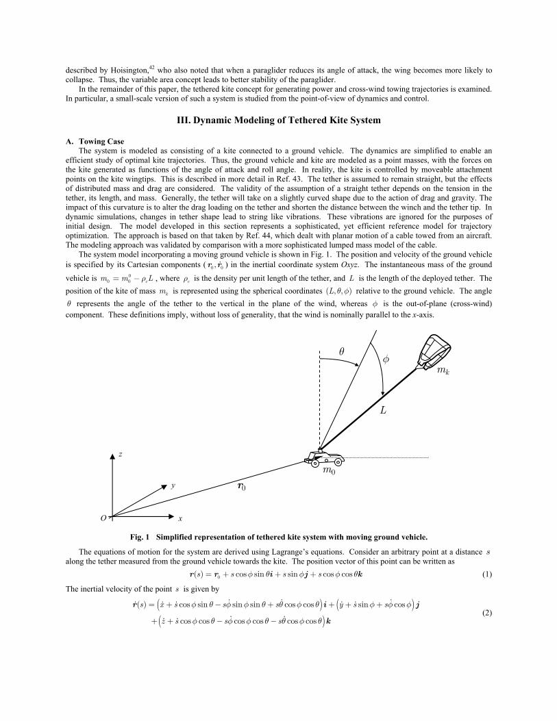
The system model incorporating a moving ground vehicle is shown in Fig. 1. The position and velocity of the ground vehicle is specified by its Cartesian components ( 0 0,r r ) in the inertial coordinate system Oxyz. The instantaneous mass of the ground
vehicle is 00 0 cm m Lρ= − , where cρ is the density per unit length of the tether, and L is the length of the deployed tether. The
position of the kite of mass km is represented using the spherical coordinates ( , , )L θ φ relative to the ground vehicle. The angle θ represents the angle of the tether to the vertical in the plane of the wind, whereas φ is the out-of-plane (cross-wind) component. These definitions imply, without loss of generality, that the wind is nominally parallel to the x-axis.
Fig. 1 Simplified representation of tethered kite system with moving ground vehicle.
The equations of motion for the system are derived using Lagrange’s equations. Consider an arbitrary point at a distance s along the tether measured from the ground vehicle towards the kite. The position vector of this point can be written as 0( ) cos sin sin cos coss s s sφ θ φ φ θ= + + +r r i j k (1)
The inertial velocity of the point s is given by
( ) ( )( )
( ) cos sin sin sin cos cos sin cos
cos cos cos cos cos cos
s x s s s y s s
z s s s
φ θ φ φ θ θ φ θ φ φ φ
φ θ φ φ θ θ φ θ
= + − + + + +
+ + − −
r i j
k (2)
x
y
z
0r
0m
km
L
θφ
O
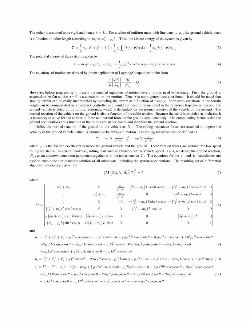
The tether is assumed to be rigid and hence s L= . For a tether of uniform mass with line density cρ , the ground vehicle mass
is a function of tether length according to 00 0 cm m Lρ= − . Thus, the kinetic energy of the system is given by
( )2 2 20
0
1 1 1( ) ( ) d ( ) ( )
2 2 2
L
c k s Lm x y z s s s m s sρ
== + + + ⋅ + ⋅∫ r r r rT (3)
The potential energy of the system is given by
20
1cos cos cos cos
2c k c km gz Lgz m gz gL m gLρ ρ θ φ θ φ= + + + +V (4)
The equations of motion are derived by direct application of Lagrange’s equations in the form
dd jq
j j
Qt q q
⎛ ⎞∂ ∂⎟⎜ ⎟⎜ − =⎟⎜ ⎟⎟⎜∂ ∂⎝ ⎠
L L (5)
However, before progressing to present the coupled equations of motion several points need to be made. First, the ground is assumed to be flat so that z = 0 is a constraint on the motion. Thus, z is not a generalized coordinate. It should be noted that sloping terrain can be easily incorporated by modeling the terrain as a function of x and y. Short-term variations in the terrain height can be compensated by a feedback controller and would not need to be included in the reference trajectories. Second, the ground vehicle is acted on by rolling resistance, which is dependent on the normal reaction of the vehicle on the ground. The normal reaction of the vehicle on the ground is also a function of the cable tension. Because the cable is modeled as inelastic, it is necessary to solve for the constraint force and normal force on the ground simultaneously. The complicating factor is that the ground accelerations are a function of the rolling resistance forces and therefore the ground reaction.
Define the normal reaction of the ground on the vehicle as zN . The rolling resistance forces are assumed to oppose the velocity of the ground vehicle, which is assumed to be always in motion. The rolling resistance can be defined as
2 2 2 2
, yf fxx z y zx y x yF N F Nμ μ
+ += − = − (6)
where μ is the friction coefficient between the ground vehicle and the ground. These friction forces are suitable for low speed rolling resistance. In general, however, rolling resistance is a function of the vehicle speed. Thus, we define the ground reaction, zN , as an unknown constraint parameter, together with the tether tension T . The equations for the z - and L - coordinates are
used to enable the simultaneous solution of all unknowns, including the system accelerations. The resulting set of differential algebraic equations are given by
[ ] , , , , ,zx y N Tθ φ⎡ ⎤ =⎢ ⎥⎣ ⎦M b (7)
where
( ) ( )( )
( ) ( )( ) ( )( ) ( ) ( )
2 2
2 2
02 20
020
2 2
2 22 3
22 2 3
0 cos cos sin sin 0
0 0 cos 0
0 0 1 sin cos cos sin 0
cos cos 0 0 cos 0 0
sin sin cos 0 0 0
k c c
k c
c c
c c
c c c
x L Lk k kx y
y Lk kx y
L Lk k
L Lk k
L L Lk k k
m m m L m L
m m m L
m L m LM
m L m L
m L m L m L
μ ρ ρ
μ ρ
ρ ρ
ρ ρ
ρ ρ ρ
θ φ θ φ
φ
θ φ θ φ
θ φ φ
θ φ φ
+
+
+ + − +
+ +
− − + − +=
+ +
− + + +
( ) ( )sin cos sin 0 0 0 1k c c km L L m Lρ θ φ ρ φ
⎡ ⎤⎢ ⎥⎢ ⎥⎢ ⎥⎢ ⎥⎢ ⎥⎢ ⎥⎢ ⎥⎢ ⎥⎢ ⎥⎢ ⎥⎢ ⎥⎢ ⎥⎢ ⎥⎢ ⎥+ +⎢ ⎥⎣ ⎦
(8)
and
0 2 2 2 2 2 21 12 2
2
cos sin cos sin cos sin sin cos cos sin
2 sin sin 2 cos cos cos sin 2 sin sin 2 cos cos
cos sin 2 s
k tx x x x k c c c
c c c k k
k k
b F F F L m L L L L
LL LL LL m L m L
m L m L
ρ φ θ φ θ ρ φ φ θ θφρ φ θ θ ρ φ θ
ρ φ φ θ θρ φ θ ρ φ θ φ φ θ θ φ θ
φ φ θ θφ
= + + − − + + +
+ − − + −
+ + 2in cos cos sinkm Lφ θ θ φ θ+
(9)
0 2 2 2 212 sin 2 cos sin sin sin 2 cos sink t
y y y y c c c c k k kb F F F L LL LL L m L m L m Lρ φφ φρ φ ρ φ ρ φ φ φ φ φ φ= + + − − − − − + (10)
0 0 2 2 2 2 21 12 20 0
2
cos cos sin sin cos cos 2 sin cos
2 cos sin cos cos 2 sin cos 2 sin sin 2 cos sin
cos cos
k tz z z k c c c c
c c k k k
k k
b F F m z m z m g L L L LL
LL LL m L m L m L
m L m L
ρ φ φ θ ρ φθ φ θ ρ θ φ θ ρ φ φ θ
ρ θ φ θ ρ φ θ φ φ θ φθ φ θ θ φ θ
φ φ θ θ
= + − − − + − + +
+ − + − +
+ + 2 2cos cos cos cos cos cosk k cm L m g Lφ θ φ θ ρ φ θ− − −
(11)
2 2 2 3 21 2
2 3
2 212
cos cos sin cos sin cos sin 2 cos
2 cos sin cos sin cos sin
t kc k c c k
k c k
b Q Q L L m Lz L z L m LL
m L gL m gL
θ θ θ ρ θ φ φ θ ρ φ θ ρ θφ φ φ θ φ
θφ φ φ ρ φ θ φ θ
= + − + + + −
+ + + (12)
2 2 21 1
2 2
3 2 2 213
2 sin cos sin cos sin cos sin cos
cos sin cos sin
k tc k k c k c
c k
b Q Q L L m LL m gL gL m Lz L z
L m L
φ φ φ ρ φ φ φ θ ρ φ θ φ θ ρ φ θ
ρ θ φ φ θ φ φ
= + − − + + + +
− − (13)
21
2 c c
2 2 2 2 2 2 2 21 12 2c c
cos cos cos cos cos cos cos cos
cos cos
kL L c c k k k
k k
b Q Lz gL m L L m g m z LL
L m L L m L
ρ φ θ ρ φ θ ρ φ θ φ θ ρ
ρ θ φ θ φ ρ φ φ
= − − − − − − −
+ + + + (14)
The generalized forces appearing on the right-hand side of Eqs. (9) through (14) are derived in the following subsection. It is important to point out that the vehicle is controlled only by movement of the tether. There is no active steering assumed on the vehicle itself (the vehicle is free to move in any direction; the direction of the tether tension controls the vehicle acceleration). Other configurations include a vehicle attached to rails such that it is constrained in its movement. This possibility will be studied in future work.
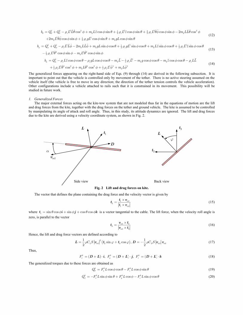
1. Generalized Forces The major external forces acting on the kite-tow system that are not modeled thus far in the equations of motion are the lift
and drag forces from the kite, together with the drag forces on the tether and ground vehicle. The kite is assumed to be controlled by manipulating its angle of attack and roll angle. Thus, in this study, its attitude dynamics are ignored. The lift and drag forces due to the kite are derived using a velocity coordinate system, as shown in Fig. 2.
Side view Back view
Fig. 2 Lift and drag forces on kite.
The vector that defines the plane containing the drag force and the velocity vector is given by
1 rel2
1 rel
×=
×t v
tt v
(15)
where 1 sin cos sin cos cosθ φ φ θ φ= + +t i j k is a vector tangential to the cable. The lift force, when the velocity roll angle is zero, is parallel to the vector
rel 23
rel 2
×=
×v t
tv t
(16)
Hence, the lift and drag force vectors are defined according to
( )2
rel 2 3 rel rel
1 1sin cos ,
2 2L DC S C Sρ ϕ ϕ ρ= + = −L v t t D v v (17)
Thus,
( ) ( ) ( ), , k k kx y zF F F= + ⋅ = + ⋅ = + ⋅D L i D L j D L k (18)
The generalized torques due to these forces are obtained as
cos cos cos sink k kx zQ F L F Lθ φ θ φ θ= − (19)
sin sin cos sin cosk k k kx y zQ F L F L F Lφ φ θ φ φ θ= − + − (20)
relv
α
D
L 1t
3t
2t
ϕ L
cos sin sin cos cosk k k kL x y zQ F F Fφ θ φ φ θ= + + (21)
The drag forces on the tether are derived by assuming that the drag tangential to the tether is negligible. The computation of the drag forces is complicated by the fact that each part of the tether is moving at a different speed. Therefore, the tether is discretized into a series of elements so that the contributions of drag from each element can be summed to obtain the total drag force and torque due to the tether. The magnitude of the relative wind component tangential to the cable is given by
rel 1 ( )cos sin ( )sin ( )cos cosx y zL x W y W z Wφ θ φ φ θ⋅ = + − + − + −v t (22)
The components of velocity normal to the cable are computed from
( )rel rel 1 1n = − ⋅v v v t t (23)
The contribution of the tether drag to the generalized forces are obtained as
12
1
212
1
2 2 2
{ sin sin cos cos ( )cos
( )cos cos ( )cos sin sin ( )cos sin cos }
e
e j j
e
e j
njt L
nx j n n nj
nLnj n n x j j x
j
x y z
F C dx
C d x W s s W x
W x W y W z
ρ
ρ φ φ θ θ φ θ φ
φ θ φ θ φ φ θ θ
=
=
∂= − ⋅
∂
= − − − + + −
− − + − + −
∑
∑
rv v
v (24)
12
1
12
1
{cos ( ( )sin sin ( )cos ( )sin cos )}
e
e j j
e
e j
njt L
ny j n n nj
nLnj n n j x y z
j
F C dy
C d s W x W y W z
ρ
ρ φ φ φ θ φ φ θ
=
=
∂= − ⋅
∂
= − + − − − + −
∑
∑
rv v
v (25)
12
1
212
1
2 2
{ sin cos cos sin ( )cos cos sin
( )cos cos sin ( )cos cos }
e
e j j
e
e j
njt L
nz j n n nj
nLnj n n z j j x
j
y z
F C dz
C d z W s s W x
W y W z
ρ
ρ φ φ θ θ φ θ φ θ θ
φ θ φ φ θ
=
=
∂= − ⋅
∂
= − − − − + −
+ − + −
∑
∑
rv v
v (26)
12
1
12
1
{ cos ( ( )cos ( )sin cos )}
e
e j j
e
e j
njt L
nj n n nj
nLnj n n j x z j
j
Q C d
C d s W x W z s
θ ρθ
ρ φ θ θ θ φ
=
=
∂= − ⋅
∂
= − − − + − +
∑
∑
rv v
v (27)
12
1
12
1
{ ( ( )sin sin ( )cos ( )sin cos )}
e
e j j
e
e j
njt L
nj n n nj
nLnj n n j j x y z
j
Q C d
C d s s W x W y W z
φ ρφ
ρ φ φ θ φ φ θ
=
=
∂= − ⋅
∂
= − + − − − + −
∑
∑
rv v
v (28)
The forces on the ground vehicle are assumed to be due to drag, which is modeled using the equations
0 0 01 1 12 2 20 0 0 0 0 0 0 0 0 0 0 0, ,x D y D z DF C A F C A F C Aρ ρ ρ= − ⋅ = − ⋅ = − ⋅r r i r r j r r k (29)
The complete set of equations of motion may be integrated after first solving the coupled differential equations for the second derivatives of the generalized coordinates together with the normal reaction and tether tension. The resulting equations are cast in state-space form.
B. Power Generation Case In the case where the ground vehicle is reduced to a stationary ground station containing a winch, the above equations can be
simplified considerably. The equations of motion are uncoupled and can be written in the form
( ) ( ) ( ) ( )2 2 2 21 1 1 13 2 3 2cos 2 cos 2 sin cos cos sin k t
k c k c k c k cm L L m L LL m L L m L gL Q Qθ θρ θ φ ρ θ φ ρ θφ φ φ ρ φ θ+ + + − + − + = + (30)
( ) ( ) ( ) ( )2 2 21 1 1 13 2 3 22 sin cos sin cos k t
k c k c k c k cm L L m L LL m L L m L gL Q Qφ φρ φ ρ φ ρ θ φ φ ρ φ θ+ + + + + − + = + (31)
( ) ( ) ( ) ( )2 2 2 21 1 12 2 2 cos cos cos k
k c c k c k c k c Lm L L L m L L m L L m L g Q Tρ ρ ρ φ ρ θ φ ρ φ θ+ + − + − + + + = − (32)
The generalized forces are given by Eqs. (19), (20), (27) and (28) with the components of the velocity of the ground vehicle set to zero.
IV. Periodic Optimal Cross-Wind Trajectories
A. Cross-Wind Towing The major objective of this paper is to establish the optimal means of flying the kite so as to produce the maximum cross-
wind control action on the ground vehicle, as well as maximum power generation. It is a relatively simple matter to utilize the system to travel downwind, which would require the system to operate at more or less a constant angle. This is by no means guaranteed to give an optimal solution. Efficient motion in the cross-wind direction will require more complex trajectories of the kite. In this section, the best way of flying the kite to maximize the cross-wind distance travelled by the vehicle is considered. To guarantee the repeatability of the maneuver for long periods, it is useful to derive the trajectory to be periodic. This means that the relative position and velocity of the kite to the vehicle is repeated with some prescribed period. In addition, the planar components of the vehicle velocity also need to be periodic. Note that this does not imply that the vehicle returns to its original position spatially, and hence the technique is potentially applicable for both short and long trips. Two specific cases are considered. The first maintains the tether at a constant length, whereas the second case allows the tether length to vary in a controlled manner within specified limits. For consistency, the numerical solution obtained for the fixed length tether case is used as the starting guess for the variable length case.
The vehicle is intended to travel for relatively long periods, for which it is assumed that there are no impediments, such as obstacles. Any practical system would need to be equipped with active steering to enable the vehicle to steer itself to its desired destination as well as to avoid hazards. However, this paper is a feasibility study of how to fly the kite to maximize cross-wind performance in the absence of active steering. The results can then be used as a baseline for further trajectory design.
The periodic optimal control problem can be stated as: Find the (pseudo)-control inputs { }( ) , ,t Lα ϕ=u and corresponding
state trajectory ( ) { , , , , , , ,t x y Lθ φ α ϕ=x , , , , }x y Lθ φ that minimizes the cost function
( )0
2 2 21 1 0 2
0
( )( ) d
ftff
tf
y tJ W t t W L t
t tα ϕ= − + − + +
− ∫ (33)
where 1W is a weighting coefficient that effectively trades the kite control variations with cross-wind performance, and 2W is a weighting coefficient that is used only when the tether length is variable. In this formulation, the period of the maneuver 0ft t− is free to be optimized. Hence, the cost function is selected so as to maximize the average cross wind distance traveled per second (average velocity), while minimizing the total control effort. The periodicity conditions are given by
0
{ , , , , , , , , , } { , , , , , , , , , }ft t t tx y L L x y L Lθ φ α ϕ θ φ θ φ α ϕ θ φ= == (34)
Hence, all states except vehicle position are periodic. In addition to the above constraints, a path constraint is enforced to ensure that the model remains realistic (rolling friction is always assumed)
2 2 1x y+ ≥ (35)
An additional constraint may need to be enforced on the tether tension to ensure that it remains positive. However, intuitively, for towing scenarios, maximum forces on the vehicle can only be generated by high tension. Hence, the tension should be kept large in the optimal solution. This has been validated from the optimal solutions in the case where the tether length is held fixed.
The kite control parameters are constrained by the following constraints
10 deg, 30 deg, 5 deg/ s, 5 deg/ s, α ϕ α ϕ≤ ≤ ≤ ≤ (36)
In the case where the tether is allowed to vary in length, some additional constraints are necessary. Controlling the tether length through the reel acceleration potentially allows rapid changes in tether tension. Because the tether cannot sustain compressive forces, a path constraint of the form minT T≥ (37)
must be enforced. In this paper, minT is set as 10 N. Furthermore, because the purpose of employing a high altitude kite is to obviate the need for fuel, it is clear that the reeling system should not consume excessive amounts of power. In fact, as will be seen in later sections, it is possible to recover spent energy through proper control of the tether length. To ensure that the net power used by the reel is at least recovered, the following integral path constraint is employed
0
d 0ft
tTL t ≥∫ (38)
The following additional constraints are imposed on the reeling
2
ref
0.3, 10 m/s, 3 m/sL
L LLΔ
≤ ≤ ≤ (39)
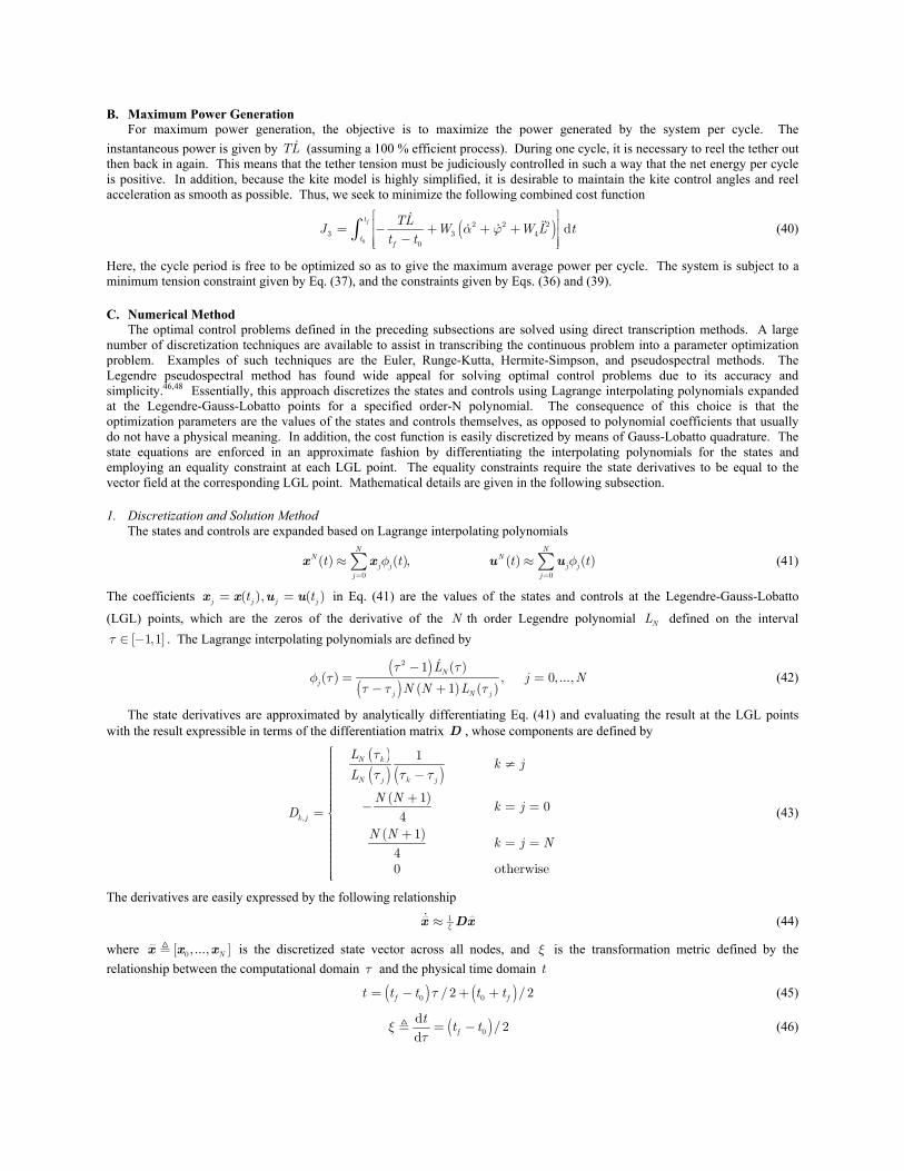
B. Maximum Power Generation For maximum power generation, the objective is to maximize the power generated by the system per cycle. The
instantaneous power is given by TL (assuming a 100 % efficient process). During one cycle, it is necessary to reel the tether out then back in again. This means that the tether tension must be judiciously controlled in such a way that the net energy per cycle is positive. In addition, because the kite model is highly simplified, it is desirable to maintain the kite control angles and reel acceleration as smooth as possible. Thus, we seek to minimize the following combined cost function
( )0
2 2 23 3 4
0
dft
tf
TLJ W W L t
t tα ϕ
⎡ ⎤⎢ ⎥= − + + +⎢ ⎥−⎢ ⎥⎣ ⎦
∫ (40)
Here, the cycle period is free to be optimized so as to give the maximum average power per cycle. The system is subject to a minimum tension constraint given by Eq. (37), and the constraints given by Eqs. (36) and (39).
C. Numerical Method The optimal control problems defined in the preceding subsections are solved using direct transcription methods. A large
number of discretization techniques are available to assist in transcribing the continuous problem into a parameter optimization problem. Examples of such techniques are the Euler, Runge-Kutta, Hermite-Simpson, and pseudospectral methods. The Legendre pseudospectral method has found wide appeal for solving optimal control problems due to its accuracy and simplicity.46,48 Essentially, this approach discretizes the states and controls using Lagrange interpolating polynomials expanded at the Legendre-Gauss-Lobatto points for a specified order-N polynomial. The consequence of this choice is that the optimization parameters are the values of the states and controls themselves, as opposed to polynomial coefficients that usually do not have a physical meaning. In addition, the cost function is easily discretized by means of Gauss-Lobatto quadrature. The state equations are enforced in an approximate fashion by differentiating the interpolating polynomials for the states and employing an equality constraint at each LGL point. The equality constraints require the state derivatives to be equal to the vector field at the corresponding LGL point. Mathematical details are given in the following subsection.
1. Discretization and Solution Method The states and controls are expanded based on Lagrange interpolating polynomials
0 0
( ) ( ), ( ) ( )N N
N Nj j j j
j j
t t t tφ φ= =
≈ ≈∑ ∑x x u u (41)
The coefficients ( ), ( )j j j jt t= =x x u u in Eq. (41) are the values of the states and controls at the Legendre-Gauss-Lobatto
(LGL) points, which are the zeros of the derivative of the N th order Legendre polynomial NL defined on the interval [ 1,1]τ ∈ − . The Lagrange interpolating polynomials are defined by
( )
( ) ( )
2 1 ( )( ) , 0, ...,
1 ( )N
j
j N j
Lj N
N N L
τ τφ τ
τ τ τ
−= =
− + (42)
The state derivatives are approximated by analytically differentiating Eq. (41) and evaluating the result at the LGL points with the result expressible in terms of the differentiation matrix D , whose components are defined by
( )( ) ( )
( )
( ),
1
10
41
40 otherwise
N k
N j k j
k j
Lk j
L
N Nk jD
N Nk j N
ττ τ τ
⎧⎪⎪ ≠⎪⎪ −⎪⎪⎪⎪ +⎪⎪ − = =⎪= ⎨⎪⎪⎪ +⎪ = =⎪⎪⎪⎪⎪⎪⎪⎩
(43)
The derivatives are easily expressed by the following relationship
1ξ≈x Dx (44)
where 0[ , ..., ]Nx x x is the discretized state vector across all nodes, and ξ is the transformation metric defined by the relationship between the computational domain τ and the physical time domain t
( ) ( )0 0/ 2 /2f ft t t t tτ= − + + (45)
( )0
d/2
d f
tt tξ
τ= − (46)
Finally, the integral cost function is discretized via a Gauss-Lobatto quadrature rule so that
0
1
1 0
( ) d ( ( )) d ( )f
Nt
j jt j
F t t F t w F tξ τ τ ξ− =
= ≈ ∑∫ ∫ (47)
where jw are the Legendre-Gauss-Lobatto weights defined by
( )
2
2 1, 0, ...,
( 1)j
N j
w k NN N L τ
= =⎡ ⎤+⎢ ⎥⎣ ⎦
(48)
The process mentioned above is automated in the software DIDO, as well as in the software DIRECT written by the first author. This software is a MATLAB interface to the solver SNOPT, which implements a quasi-Newton algorithm.
D. Some Safety Considerations Some potential issues related to the cross-wind towing application have already been alluded to, such as the need for active
steering to avoid obstacles and other potential hazards. One of the advantages of using a kite in the system instead of other lifting bodies such as a rigid wing is that it reduces potential damage that can be caused if the system fails. Important considerations are the implications of tether severance. In either of the applications, the biggest risk is how the system behaves when the wind drops to zero or if the cable breaks. The danger increases as the cable length increases due to the radius of possible damage increasing with cable length. Furthermore, for very large scale systems, the cable will be a significant fraction of the system weight. Hence, for power generation, placement of the system will need to take into consideration issues such as system failure, as well as hazards to other air vehicles.
V. Tracking Controller One of the challenges with using a kite-type system for extracting wind energy is that it is likely to be sensitive to gusts and turbulence. In other words, variations in the wind speed could disturb the system significantly, causing it to enter into an unrecoverable spin, dive, or collapse. These are issues that will need to be addressed in future studies. However, it is important to be able to establish whether the system is capable of following a desired trajectory determined in the presence of variations in the wind speed around the mean. In this study, a simple linear receding horizon based feedback controller is used to track the trajectories. The control inputs to the model are assumed to be the kite angle of attack and velocity roll angle. The feedback controller is essentially a PID controller based on the quanties , , , , , , ,x x y yδ δ δ δ δθ δθ δφ δφ . The corresponding control gains are determined by solving the following optimization problem in state-space form: find the controls ( )tδu that minimize the quadratic performance index
*1 1( ) ( ) ( ) ( ) ( ) ( ) d
2 2
ht T
h f ht
J t T t T t t t t tδ δ δ δ δ δ δ+
⎡ ⎤= + + + +⎣ ⎦∫x S x x Q x u R u (49)
subject to the linearized state equations ( ) ( )t tδ δ δ= +x A x B u (50)
the initial conditions
*( ) ( ) ( )t t t tδ = = −x x x (51)
and possibly the terminal constraints
*( ) 0ht t Tδ = + =x (52)
where xnδ ∈x are the perturbed state variables, unδ ∈u are the perturbed controls, x xn n×∈A is the time-varying system state influence matrix, x un n×∈B is the time-varying control influence matrix, x xn n×∈Q is a positive semi-definite weighting matrix that penalizes the deviations of the perturbed states, u un n×∈R is a positive definite weight matrix that penalizes the deviations of the perturbed controls, and x xn n
f×∈S is a positive semi-definite terminal weight matrix that penalizes the
deviations of the perturbed states at the end of the future horizon hT . The solution of the above optimization problem is obtained using a Gauss-Lobatto49 or Legendre pseudospectral discretization50 combined with standard results from quadratic programming. The final result is a feedback controller of the form
( ) ( ; , ) ( )ht t N T tδ δu K x (53)
The feedback control gains are periodic for a given periodic trajectory and are stored with the reference trajectory. Note that integral terms can be included to make the controller more robust to variations in the system parameters, such as the cable drag coefficient. Note also that full state feedback is assumed for the controller. The vehicle states can be measured from an integrated navigation solution, whereas the kite/tether states can be measured from a combination of GPS on the kite and the tether tension vector at the vehicle. These state measurements would be used within a filter, such as an extended or unscented Kalman filter, to derive the full system state vector. See Refs. 45 and 46 for examples of real kite measurements.
VI. Numerical Results
A. Kite Pulling Case
1. Length Fixed Optimal trajectories for the system were generated with the time domain discretized into 160 segments and the tether divided
into 10 elements for computation of the drag forces. The wind field is assumed to be of the form ( )1 exp /x sW W h h⎡ ⎤= − −⎣ ⎦
where sh is a scaling height. In this model, the wind strength asymptotes to the value of W as the altitude increases. The assumed system parameters that are used for this analysis are given in Table 1. It is important to note that the precise values that are used here are not important. The goal of this study is to develop an understanding of the general form of the optimal maneuvers required for cross-wind towing and/or power generation. The mass of the vehicle that is used for towing is made relatively large to ensure that the model remains valid, i.e., the vehicle is always in contact with ground.
Table 1 Nominal system parameters.
Parameter Nominal Value Kite mass 50 kg Vehicle mass 5000 kg Tether length, L 1000 m* Tether density, cρ 3.14 kg/km Tether diameter, d 2 mm Cable normal drag coefficient,
NDC 1.2
Vehicle projected drag area, DC A 1.0 Friction coefficient 0.1 Lift curve slope, LC α
4.4 /rad
Zero-lift drag, 0D
C 0.02
Lift-induced drag, K 0.1 Kite wing area, S 25 m2
*nominal length for power generation is 2000 m In the case where the tether length is held fixed, the optimal kite trajectories relative to the ground vehicle are shown in Fig.
3. These results are generated with sh = 100 m with W ranging from 10 m/s to 15 m/s in increments of 1 m/s. Fig. 3 demonstrates that the shape of the trajectories are almost identical for different values of the mean wind. After noting that the vehicle is located at the origin, it is evident that the kite maintains a mean cross-wind position of approximately 400 m, which is similar to the mean altitude of the kite. Thus, the kite does not benefit from the larger winds that are present at higher altitudes due to the limit placed on the tether length. For all wind strengths, the kite performs a large, elliptic-like trajectory in the vertical plane normal to the wind direction. The maneuver is completed with a smaller, almost circular trajectory at a slightly higher altitude. It can be seen that the trajectories benefit from the cross-wind motion of the kite. This cross-wind motion is able to increase the relative wind speed at the kite by a significant fraction, as shown in Fig. 4. The mean increase in relative wind is approximately 42.2% over the true wind speed at the kite, but significant instantaneous increases of up to 150% are possible. This is the primary reason why it is so beneficial to optimize the kite motion. The actual change in forces on the kite is proportional to the square of the relative wind speed. On average, the force increase on the kite relative to the case where forces are produced only from the true wind is 113.5%.
A summary of the optimal trajectories as a function of the maximum wind speed is given in Table 2. The results show that the cycle time is on the order of 68 sec for wind speeds between 10 and 14 m/s, but drops to 61.5 sec for a wind speed of 15 m/s. The decrease in the cycle time causes the downwind and cross-wind distance per cycle to decrease relative to the 14 m/s case, but the actual average cross-wind velocity increases. Furthermore, an increase in wind speed leads to higher ratios of the cross-wind distance to downwind distance travelled per cycle.
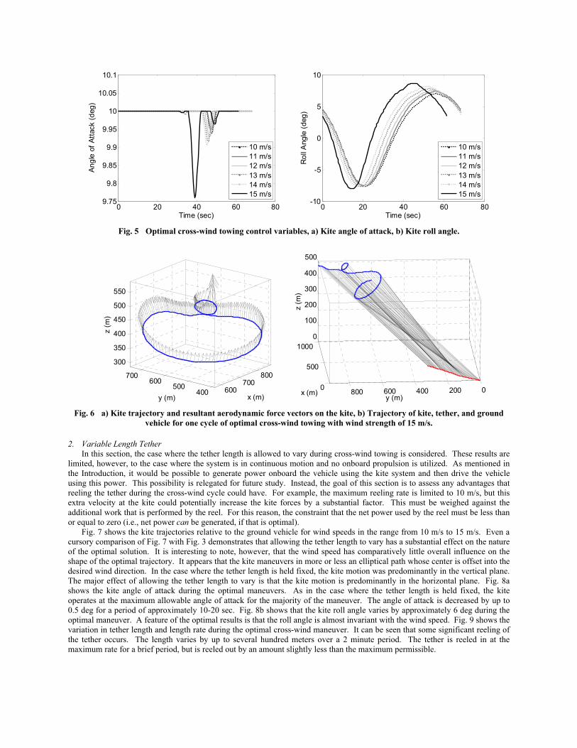
Fig. 5a shows that the kite is operated at the maximum angle of attack of 10 deg for the vast majority of the cycle. The decrease in angle of attack occurs when the kite is on the upper “smaller” circle. The kite roll angle is shown in Fig. 5b. It is important to realize that the definition of the roll angle is not relative to the inertial axes, but relative to the direction of the tether. Therefore, a kite with zero roll angle implies that the lift vector is in the plane of the tether and the relative wind vector. For this reason, the roll angle only varies by a relatively small amount with a peak of approximately 7.5 deg. Fig. 6a shows an example of the resultant aerodynamic forces on the kite for the case where W = 15 m/s. This plot illustrates that the aerodynamic forces are predominantly directed in the downwind direction with significant cross-wind components. This is in addition to the obvious vertical components required to sustain the kite altitude. Fig. 6b summarizes the complete picture of one cycle for the example of
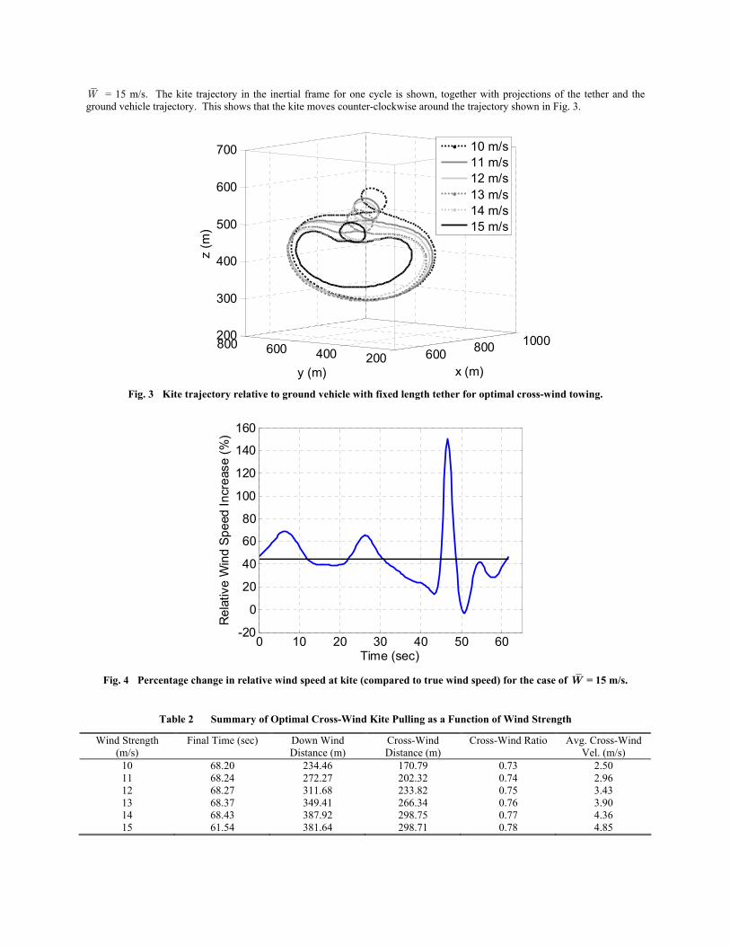
W = 15 m/s. The kite trajectory in the inertial frame for one cycle is shown, together with projections of the tether and the ground vehicle trajectory. This shows that the kite moves counter-clockwise around the trajectory shown in Fig. 3.
600 800 1000200400600800
200
300
400
500
600
700
x (m)y (m)
z (m
)
10 m/s11 m/s12 m/s13 m/s14 m/s15 m/s
Fig. 3 Kite trajectory relative to ground vehicle with fixed length tether for optimal cross-wind towing.
0 10 20 30 40 50 60-20
0
20
40
60
80
100
120
140
160
Time (sec)
Rel
ativ
e W
ind
Spee
d In
crea
se (%
)
Fig. 4 Percentage change in relative wind speed at kite (compared to true wind speed) for the case of W = 15 m/s.
Table 2 Summary of Optimal Cross-Wind Kite Pulling as a Function of Wind Strength
Wind Strength (m/s)
Final Time (sec) Down Wind Distance (m)
Cross-Wind Distance (m)
Cross-Wind Ratio Avg. Cross-Wind Vel. (m/s)
10 68.20 234.46 170.79 0.73 2.50 11 68.24 272.27 202.32 0.74 2.96 12 68.27 311.68 233.82 0.75 3.43 13 68.37 349.41 266.34 0.76 3.90 14 68.43 387.92 298.75 0.77 4.36 15 61.54 381.64 298.71 0.78 4.85
0 20 40 60 809.75
9.8
9.85
9.9
9.95
10
10.05
10.1
Time (sec)
Angl
e of
Atta
ck (d
eg)
10 m/s11 m/s12 m/s13 m/s14 m/s15 m/s
0 20 40 60 80-10
-5
0
5
10
Time (sec)
Rol
l Ang
le (d
eg)
10 m/s11 m/s12 m/s13 m/s14 m/s15 m/s
Fig. 5 Optimal cross-wind towing control variables, a) Kite angle of attack, b) Kite roll angle.
600700
800
400500
600700
300
350
400
450
500
550
x (m)y (m)
z (m
)
0
500
1000
0200400600800
0
100
200
300
400
500
y (m)x (m)
z (m
)
Fig. 6 a) Kite trajectory and resultant aerodynamic force vectors on the kite, b) Trajectory of kite, tether, and ground
vehicle for one cycle of optimal cross-wind towing with wind strength of 15 m/s.
2. Variable Length Tether In this section, the case where the tether length is allowed to vary during cross-wind towing is considered. These results are
limited, however, to the case where the system is in continuous motion and no onboard propulsion is utilized. As mentioned in the Introduction, it would be possible to generate power onboard the vehicle using the kite system and then drive the vehicle using this power. This possibility is relegated for future study. Instead, the goal of this section is to assess any advantages that reeling the tether during the cross-wind cycle could have. For example, the maximum reeling rate is limited to 10 m/s, but this extra velocity at the kite could potentially increase the kite forces by a substantial factor. This must be weighed against the additional work that is performed by the reel. For this reason, the constraint that the net power used by the reel must be less than or equal to zero (i.e., net power can be generated, if that is optimal).
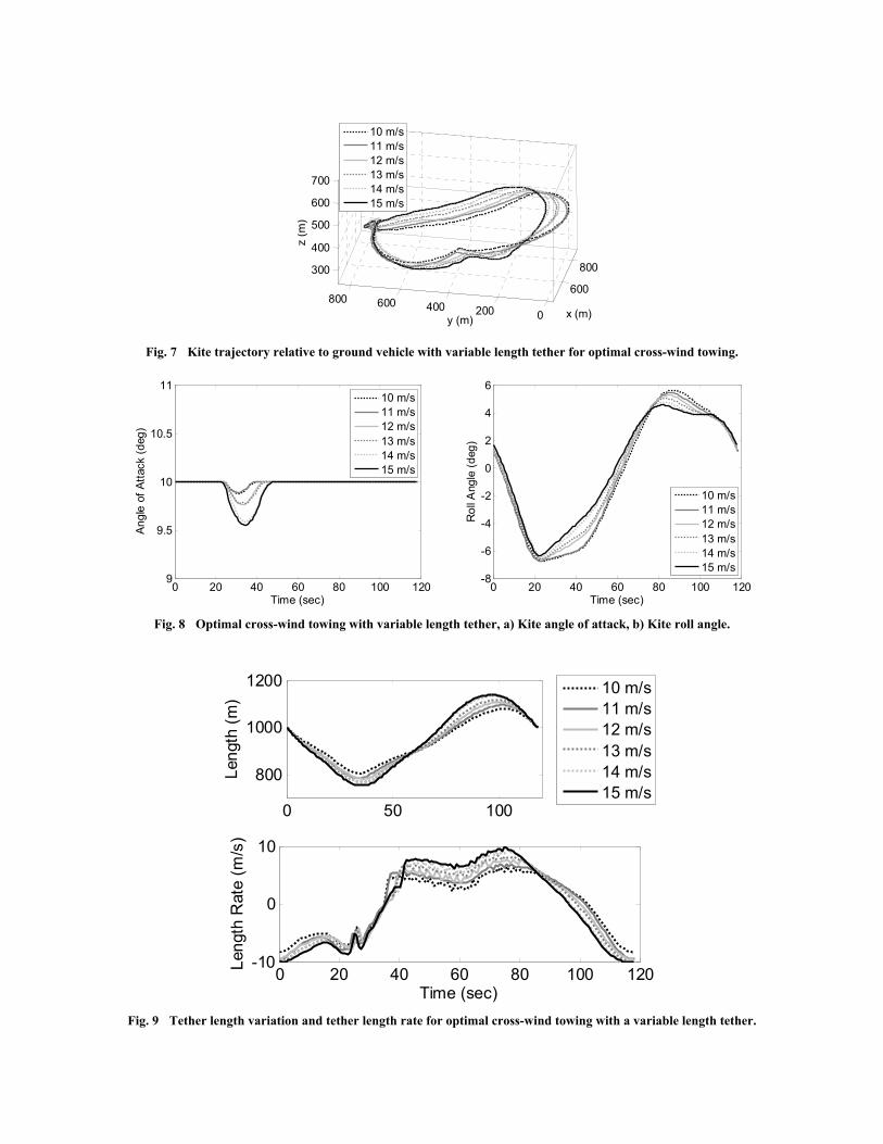
Fig. 7 shows the kite trajectories relative to the ground vehicle for wind speeds in the range from 10 m/s to 15 m/s. Even a cursory comparison of Fig. 7 with Fig. 3 demonstrates that allowing the tether length to vary has a substantial effect on the nature of the optimal solution. It is interesting to note, however, that the wind speed has comparatively little overall influence on the shape of the optimal trajectory. It appears that the kite maneuvers in more or less an elliptical path whose center is offset into the desired wind direction. In the case where the tether length is held fixed, the kite motion was predominantly in the vertical plane. The major effect of allowing the tether length to vary is that the kite motion is predominantly in the horizontal plane. Fig. 8a shows the kite angle of attack during the optimal maneuvers. As in the case where the tether length is held fixed, the kite operates at the maximum allowable angle of attack for the majority of the maneuver. The angle of attack is decreased by up to 0.5 deg for a period of approximately 10-20 sec. Fig. 8b shows that the kite roll angle varies by approximately 6 deg during the optimal maneuver. A feature of the optimal results is that the roll angle is almost invariant with the wind speed. Fig. 9 shows the variation in tether length and length rate during the optimal cross-wind maneuver. It can be seen that some significant reeling of the tether occurs. The length varies by up to several hundred meters over a 2 minute period. The tether is reeled in at the maximum rate for a brief period, but is reeled out by an amount slightly less than the maximum permissible.
600
800
0200400600800
300
400
500
600
700
x (m)y (m)
z
(m)
10 m/s11 m/s12 m/s13 m/s14 m/s15 m/s
Fig. 7 Kite trajectory relative to ground vehicle with variable length tether for optimal cross-wind towing.
0 20 40 60 80 100 1209
9.5
10
10.5
11
Time (sec)
Angl
e of
Atta
ck (d
eg)
10 m/s11 m/s12 m/s13 m/s14 m/s15 m/s
0 20 40 60 80 100 120-8
-6
-4
-2
0
2
4
6
Time (sec)
Rol
l Ang
le (d
eg)
10 m/s11 m/s12 m/s13 m/s14 m/s15 m/s
Fig. 8 Optimal cross-wind towing with variable length tether, a) Kite angle of attack, b) Kite roll angle.
0 50 100
800
1000
1200
Leng
th (m
)
0 20 40 60 80 100 120-10
0
10
Time (sec)
Leng
th R
ate
(m/s
)
10 m/s11 m/s12 m/s13 m/s14 m/s15 m/s
Fig. 9 Tether length variation and tether length rate for optimal cross-wind towing with a variable length tether.
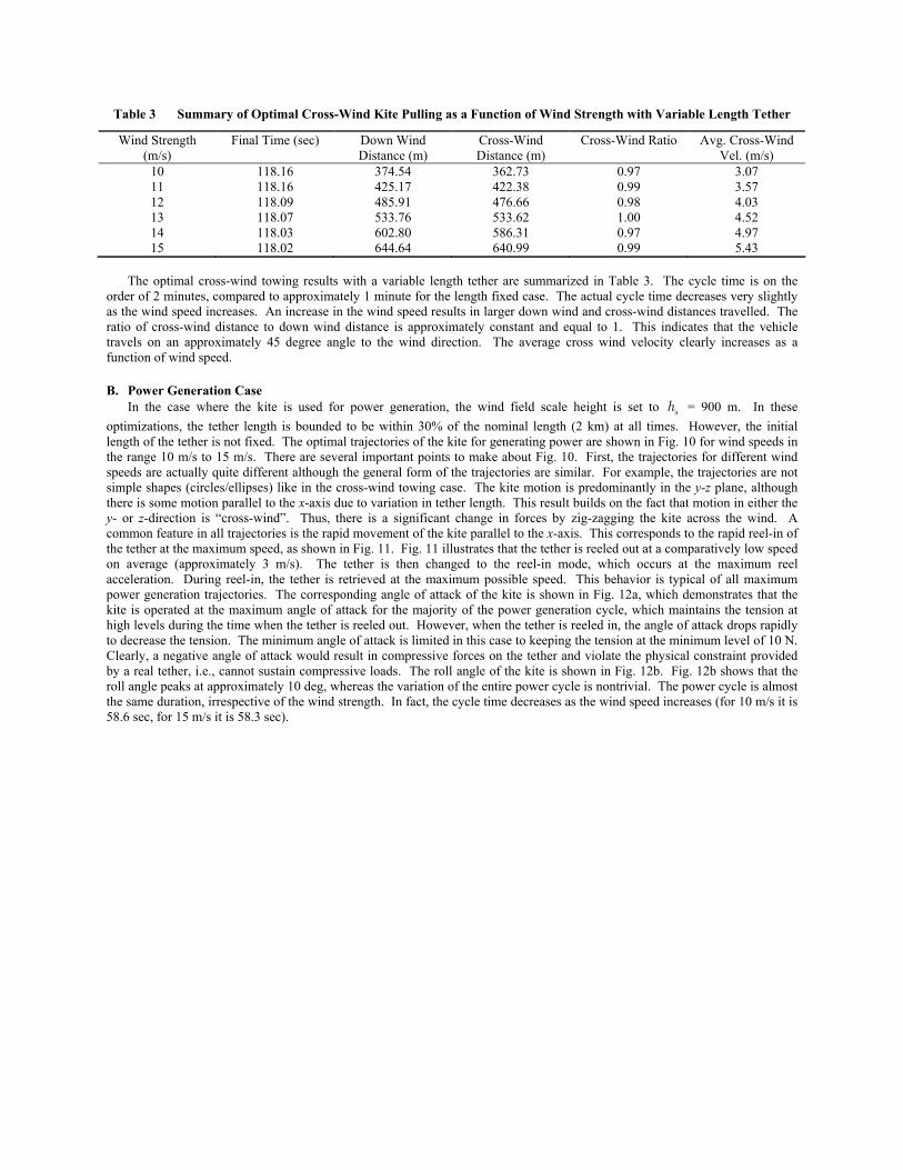
Table 3 Summary of Optimal Cross-Wind Kite Pulling as a Function of Wind Strength with Variable Length Tether
Wind Strength (m/s)
Final Time (sec) Down Wind Distance (m)
Cross-Wind Distance (m)
Cross-Wind Ratio Avg. Cross-Wind Vel. (m/s)
10 118.16 374.54 362.73 0.97 3.07 11 118.16 425.17 422.38 0.99 3.57 12 118.09 485.91 476.66 0.98 4.03 13 118.07 533.76 533.62 1.00 4.52 14 118.03 602.80 586.31 0.97 4.97 15 118.02 644.64 640.99 0.99 5.43
The optimal cross-wind towing results with a variable length tether are summarized in Table 3. The cycle time is on the
order of 2 minutes, compared to approximately 1 minute for the length fixed case. The actual cycle time decreases very slightly as the wind speed increases. An increase in the wind speed results in larger down wind and cross-wind distances travelled. The ratio of cross-wind distance to down wind distance is approximately constant and equal to 1. This indicates that the vehicle travels on an approximately 45 degree angle to the wind direction. The average cross wind velocity clearly increases as a function of wind speed.
B. Power Generation Case In the case where the kite is used for power generation, the wind field scale height is set to sh = 900 m. In these
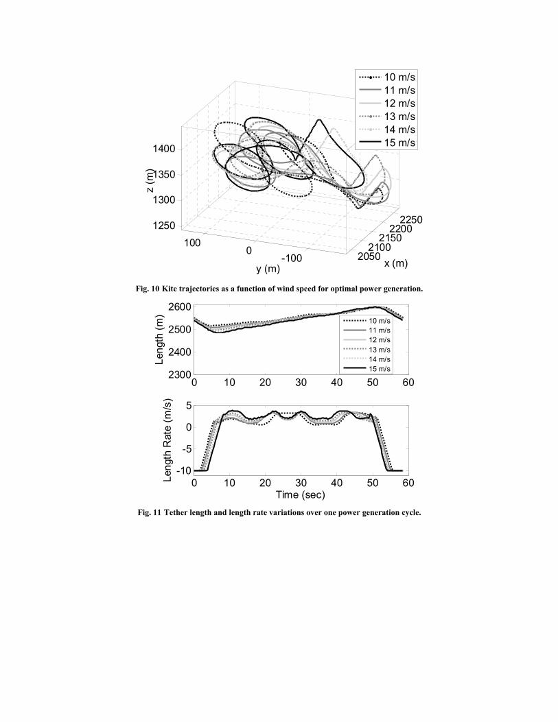
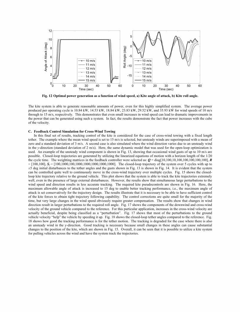
optimizations, the tether length is bounded to be within 30% of the nominal length (2 km) at all times. However, the initial length of the tether is not fixed. The optimal trajectories of the kite for generating power are shown in Fig. 10 for wind speeds in the range 10 m/s to 15 m/s. There are several important points to make about Fig. 10. First, the trajectories for different wind speeds are actually quite different although the general form of the trajectories are similar. For example, the trajectories are not simple shapes (circles/ellipses) like in the cross-wind towing case. The kite motion is predominantly in the y-z plane, although there is some motion parallel to the x-axis due to variation in tether length. This result builds on the fact that motion in either the y- or z-direction is “cross-wind”. Thus, there is a significant change in forces by zig-zagging the kite across the wind. A common feature in all trajectories is the rapid movement of the kite parallel to the x-axis. This corresponds to the rapid reel-in of the tether at the maximum speed, as shown in Fig. 11. Fig. 11 illustrates that the tether is reeled out at a comparatively low speed on average (approximately 3 m/s). The tether is then changed to the reel-in mode, which occurs at the maximum reel acceleration. During reel-in, the tether is retrieved at the maximum possible speed. This behavior is typical of all maximum power generation trajectories. The corresponding angle of attack of the kite is shown in Fig. 12a, which demonstrates that the kite is operated at the maximum angle of attack for the majority of the power generation cycle, which maintains the tension at high levels during the time when the tether is reeled out. However, when the tether is reeled in, the angle of attack drops rapidly to decrease the tension. The minimum angle of attack is limited in this case to keeping the tension at the minimum level of 10 N. Clearly, a negative angle of attack would result in compressive forces on the tether and violate the physical constraint provided by a real tether, i.e., cannot sustain compressive loads. The roll angle of the kite is shown in Fig. 12b. Fig. 12b shows that the roll angle peaks at approximately 10 deg, whereas the variation of the entire power cycle is nontrivial. The power cycle is almost the same duration, irrespective of the wind strength. In fact, the cycle time decreases as the wind speed increases (for 10 m/s it is 58.6 sec, for 15 m/s it is 58.3 sec).
20502100
21502200
2250
-1000
1001250
1300
1350
1400
x (m)y (m)
z (m
)
10 m/s11 m/s12 m/s13 m/s14 m/s15 m/s
Fig. 10 Kite trajectories as a function of wind speed for optimal power generation.
0 10 20 30 40 50 602300
2400
2500
2600
Leng
th (m
)
0 10 20 30 40 50 60-10
-5
0
5
Time (sec)
Leng
th R
ate
(m/s
)
10 m/s11 m/s12 m/s13 m/s14 m/s15 m/s
Fig. 11 Tether length and length rate variations over one power generation cycle.
0 10 20 30 40 50 600
2
4
6
8
10
12
Time (sec)
Angl
e of
Atta
ck (d
eg)
10 m/s11 m/s12 m/s13 m/s14 m/s15 m/s
0 10 20 30 40 50 60
-15
-10
-5
0
5
Time (sec)
Rol
l Ang
le (d
eg)
10 m/s11 m/s12 m/s13 m/s14 m/s15 m/s
Fig. 12 Optimal power generation as a function of wind speed, a) Kite angle of attack, b) Kite roll angle.
The kite system is able to generate reasonable amounts of power, even for this highly simplified system. The average power produced per operating cycle is 10.84 kW, 14.53 kW, 18.84 kW, 23.83 kW, 29.52 kW, and 35.93 kW for wind speeds of 10 m/s through to 15 m/s, respectively. This demonstrates that even small increases in wind speed can lead to dramatic improvements in the power that can be generated using such a system. In fact, the results demonstrate the fact that power increases with the cube of the velocity.
C. Feedback Control Simulation for Cross-Wind Towing In this final set of results, tracking control of the kite is considered for the case of cross-wind towing with a fixed length
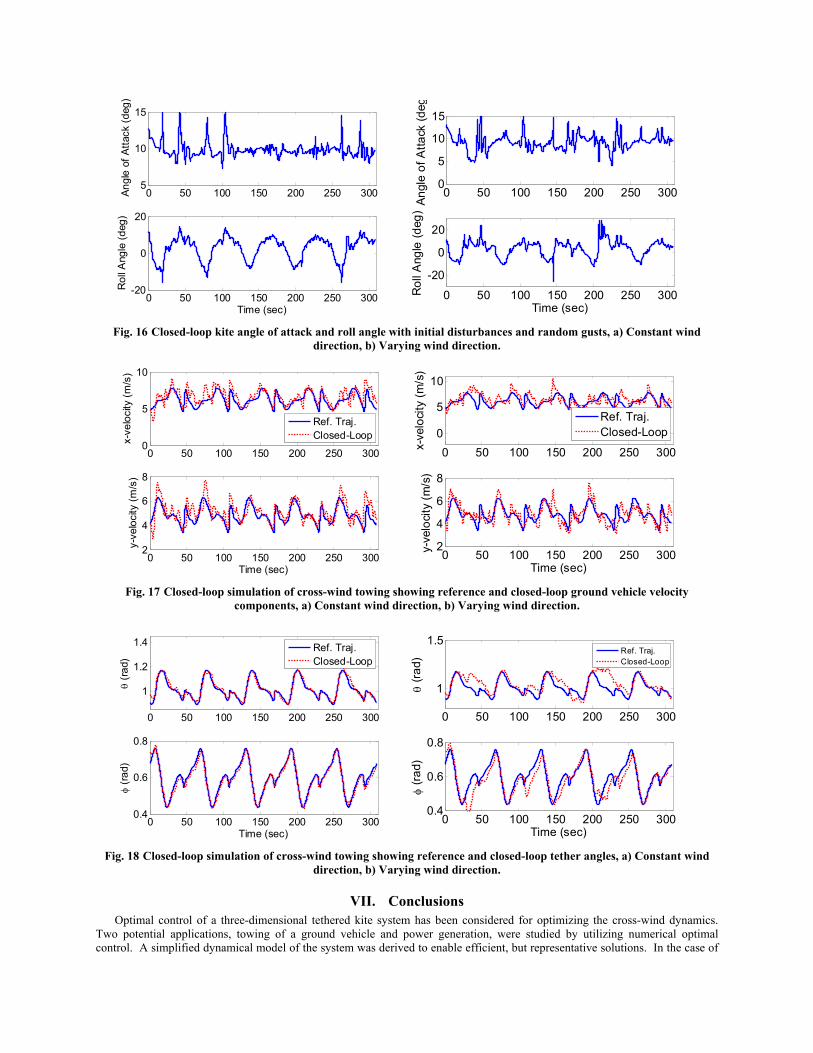
tether. The example where the mean wind speed is set to 15 m/s is selected, but unsteady winds are superimposed with a mean of zero and a standard deviation of 3 m/s. A second case is also simulated where the wind direction varies due to an unsteady wind in the y-direction (standard deviation of 2 m/s). Here, the same dynamic model that was used for the open-loop optimization is used. An example of the unsteady wind component is shown in Fig. 13, showing that occasional wind gusts of up to 10 m/s are possible. Closed-loop trajectories are generated by utilizing the linearized equations of motion with a horizon length of the 1/20 the cycle time. The weighting matrices in the feedback controller were selected as: Q = diag[10,100,10,100,100,100,100,100], R = [100,100], Sf = [100,1000,100,1000,1000,1000,1000,1000]. The closed-loop trajectory of the system over 5 cycles with up to ±5 deg initial disturbances to the tether angles and the gusts shown in Fig. 13 is shown in Fig. 14. It is evident that the system can be controlled quite well to continuously move in the cross-wind trajectory over multiple cycles. Fig. 15 shows the closed-loop kite trajectory relative to the ground vehicle. This plot shows that the system is able to track the kite trajectories extremely well, even in the presence of large external disturbances. However, the results show that simultaneous large perturbations to the wind speed and direction results in less accurate tracking. The required kite pseudocontrols are shown in Fig. 16. Here, the maximum allowable angle of attack is increased to 15 deg to enable better tracking performance, i.e., the maximum angle of attack is set conservatively for the trajectory design. The results illustrate that it is necessary to be able to have sufficient control of the kite forces to obtain tight trajectory following capability. The control corrections are quite small for the majority of the time, but very large changes in the wind speed obviously require greater compensation. The results show that changes in wind direction result in larger perturbations to the required roll angle. Fig. 17 shows the components of the downwind and cross-wind velocity of the ground vehicle compared to the reference. For this particular application, increases in the cross-wind velocity are actually beneficial, despite being classified as a “perturbation”. Fig. 17 shows that most of the perturbations to the ground vehicle velocity “help” the vehicle by speeding it up. Fig. 18 shows the closed-loop tether angles compared to the reference. Fig. 18 shows how good the tracking performance is for the tether motion. The tracking is degraded for the case where there is also an unsteady wind in the y-direction. Good tracking is necessary because small changes in these angles can cause substantial changes to the position of the kite, which are shown in Fig. 15. Overall, it can be seen that it is possible to utilize a kite system for pulling vehicles across the wind and have the system track the trajectories.

0 50 100 150 200 250 300-15
-10
-5
0
5
10
15
Time (sec)
Uns
tead
y W
ind
Com
pone
nt (m
/s)
0 50 100 150 200 250 300-10
0
10
Uns
tead
y W
x (m/s
)
0 50 100 150 200 250 300-10
0
10
Time (sec)
Uns
tead
y W
y (m/s
)
Fig. 13 Unsteady wind component for closed-loop simulation, a) Constant wind direction, b) Varying wind direction.
01000
2000
0500100015002000
0
500
y (m)x (m)
z (m
)
01000
2000
0500100015002000
0
500
y (m)x (m)
z (m
)
Fig. 14 Closed-loop simulation of optimal cross-wind towing over 5 cycles with initial disturbances and random gusts, a)
Constant wind direction, b) Varying wind direction.
600700
800
450500550600650
350
400
450
500
x (m)y (m)
z (m
)
600700
800
400500600700300
350
400
450
500
x (m)y (m)
z (m
)
Fig. 15 Closed-loop simulation of kite trajectory relative to ground vehicle with initial disturbances and random gusts, a)
Constant wind direction, b) Varying wind direction.
0 50 100 150 200 250 3005
10
15An
gle
of A
ttack
(deg
)
0 50 100 150 200 250 300-20
0
20
Rol
l Ang
le (d
eg)
Time (sec)
0 50 100 150 200 250 3000
5
10
15
Angl
e of
Atta
ck (d
eg
0 50 100 150 200 250 300
-20
0
20
Rol
l Ang
le (d
eg)
Time (sec) Fig. 16 Closed-loop kite angle of attack and roll angle with initial disturbances and random gusts, a) Constant wind
direction, b) Varying wind direction.
0 50 100 150 200 250 3000
5
10
x-ve
loci
ty (m
/s)
Ref. Traj.Closed-Loop
0 50 100 150 200 250 3002
4
6
8
Time (sec)
y-ve
loci
ty (m
/s)
0 50 100 150 200 250 3000
5
10
x-ve
loci
ty (m
/s)
Ref. Traj.Closed-Loop
0 50 100 150 200 250 3002
4
6
8
Time (sec)
y-ve
loci
ty (m
/s)
Fig. 17 Closed-loop simulation of cross-wind towing showing reference and closed-loop ground vehicle velocity
components, a) Constant wind direction, b) Varying wind direction.
0 50 100 150 200 250 300
1
1.2
1.4
θ (ra
d)
Ref. Traj.Closed-Loop
0 50 100 150 200 250 3000.4
0.6
0.8
Time (sec)
φ (ra
d)
0 50 100 150 200 250 300
1
1.5
θ (ra
d)
Ref. Traj.Closed-Loop
0 50 100 150 200 250 3000.4
0.6
0.8
Time (sec)
φ (ra
d)
Fig. 18 Closed-loop simulation of cross-wind towing showing reference and closed-loop tether angles, a) Constant wind
direction, b) Varying wind direction.
VII. Conclusions Optimal control of a three-dimensional tethered kite system has been considered for optimizing the cross-wind dynamics.
Two potential applications, towing of a ground vehicle and power generation, were studied by utilizing numerical optimal control. A simplified dynamical model of the system was derived to enable efficient, but representative solutions. In the case of

cross-wind towing, results show that higher wind speeds are able to produce more useful work for towing the vehicle across the wind. However, it was also found that allowing the tether to vary in length results in improved cross-wind performance measured in terms of average cross-wind velocity. The variations in length can be achieved in such a way that no net energy is expended onboard the vehicle. All energy is generated using the wind itself. In the case of optimal power generation, highly complex trajectories were generated as a function of wind strength. The results show that the kite makes very efficient use of cross-wind motions to generate significantly higher aerodynamic forces, which results in large tensions. The results also demonstrate that the average power generated by the system increases with the cube of the wind velocity. Finally, a tracking controller was utilized to illustrate that cross-wind towing trajectories can be tracked in the presence of unsteady winds.
References 1 Carpenter, H.G., “Tethered Aircraft Having Remotely Controlled Angle of Attack,” US Patent 5,931,416. 2 Carpenter, H.G., “Tethered Aircraft System for Gathering Energy From Wind,” US Patent 6,254,034. 3 Etkin, B., Dynamics of Atmospheric Flight, Wiley, New York, 1972. 4 Sagrillo, M., “Site Analysis for Wind Generators, Part 1: Average Wind Speed,” Home Power, Vol. 40, April/May 1994,
pp.86-90. 5 Roberts, B.W., and Shepard, D.H., “Unmanned Rotorcraft to Generate Electricity using Upper Atmospheric Winds,”
Australian International Aerospace Congress, Brisbane, July 2003. 6 Manalis, M.S., “Airborne Windmills: Energy Source for Communication Aerostats,” AIAA Lighter Than Air Technology
Conference, AIAA Paper 75-923, July 1975. 7 Manalis, M.S., “Airborne Windmills and Communication Aerostats,” Journal of Aircraft, Vol. 13, No. 7, 1976, pp.543-544. 8 Riegler, G., and Riedler, W., “Tethered Wind Systems for the Generation of Electricity,” Journal of Solar Energy
Engineering, Vol. 106, 1984, pp.177-181. 9 Riegler, G., Riedler, W., and Horvath, E., “Transformation of Wind Energy by a High-Altitude Power Plant,” Journal of
Energy, Vol. 7, No. 1, 1983, pp.92-94. 10 Manius, P.C., and Sawford, B.L., “A Self-Contained Tethered Balloon Sounding System,” J. Phys. E: Sci. Instrum., Vol.
11, 1978, pp.153-157. 11 Grant, D.A., and Rand, J.L., “Dynamic Analysis of an Ascending High Altitude Tethered Balloon System,” AIAA Paper
96-0578, Jan. 1996. 12 Colozza, A., and Dolca, J.L., “High-Altitude, Long-Endurance Airships for Coastal Surveillane,” NASA TM-2005-213427,
Glenn Research Center, Feb. 2005. 13 Nahon, M., Gilardi, G., and Lamber, C., “Dynamics/Control of a Radio Telescope Receiver Supported by a Tethered
Aerostat,” Journal of Guidance, Control, and Dynamics, Vol. 25, No. 6, 2002, pp.1107-1115. 14 Deschenes, F., and Nahon, M., “Design Improvements for a Multi-Tethered Aerostat System,” AIAA Paper 2005-6126,
Aug. 2005. 15 Onda, M., and Morikawa, Y., “High-Altitude Lighter-Than-Air Powered Platform,” International Pacific Air and Space
Technology Conference and Aircraft Symposium, SAE Paper 912054, pp.687-694, 1991. 16 Krausman, J.A., “Investigation of Various Parameters Affecting Altitude Performance of Tethered Aerostats,” AIAA Paper
95-1625, 1995. 17 Every, M.J., King, R., and Weaver, D.S., “Vortex-Excited Vibrations of Cylinders and Cables and Their Suppression,”
Ocean Engineering, Vol. 9, No. 2, 1982, pp.135-157. 18 Fletcher, C.A.J., and Roberts, B.W., “Electricity Generation from Jet-Stream Winds,” Journal of Energy, Vol. 3, 1979,
pp.241-249. 19 Fletcher, C.A.J., “On the Rotary Wing Concept for Jet Stream Electricity Generation,” Journal of Energy, Vol. 7, No. 1,
1983, pp.90-92. 20 Rye, D.C., “Longitudinal Stability of a Hovering, Tethered Rotorcraft,” Journal of Guidance, Control, and Dynamics, Vol.
8, No. 6, 1985, pp.743-752. 21 Fry, C.M., and Hise, H.W., “Wind Driven, High Altitude Power Apparatus,” US Patent 4,084,102, April 1978. 22 Kling, A., “Wind Driven Power Plant,” US Patent 4,073,516, Feb. 1978. 23 Pugh, P.F., “Wind Generator Kite System,” US Patent 4,486,669, Dec. 1984. 24 Biscomb, L.I., “Multiple Wind Turbine Tethered Airfoil Wind Energy Conversion System,” US Patent 4,285,481, Aug.
1981. 25 Watson, W.K., “Airship-Floated Wind Turbine,” US Patent 4,491,739, Jan. 1985. 26 Shepard, D.H., “Power Generation from High Altitude Winds,” US Patent 4,659,940, April 1987. 27 Rundle, C.V., “Tethered Rotary Kite,” US Patent 5,149,020, Sept. 1992. 28 Roberts, B.W., “Windmill Kite,” US Patent 6,781,254, Aug. 2004. 29 Mouton, W.J., and Thompson, D.F., “Airship Power Turbine,” US Patent 4,166,596, Sept. 1979. 30 Ockels, W.J., “Laddermill, a Novel Concept to Exploit the Energy in the Airspace,” Aircraft Design, Vol. 4, 2001, pp.81-
97. 31 Meijaard, J.P., Ockels, W.J., and Schwab, A.L., “Modelling of the Dynamic Behaviour of a Laddermill, A Novel Concept
to Exploit Wind Energy,” Proceedings of the Third International Symposium on Cable Dynamics, Norway, Aug. 1999, pp.229-234.
32 Lansdorp, B., and Ockels, W.J., “Comparison of Concepts for High-Altitude Wind Energy Generation with Ground Based Generator,” Proceedings of the NRE 2005 Conference, Beijing, China, pp.409-417.
33 Lansdorp, B., Remes, B., and Ockels, W.J., “Design and Testing of a Remotely Controlled Surfkite for the Laddermill,” World Wind Energy Conference, Melbourne, Australia, Nov. 2005.
34 Lansdorp, B., and Williams, P., “The Laddermill - Innovative Wind Energy from High Altitudes in Holland and Australia,” Paper presented at Wind Power 2006, Adelaide, Australia, September 2006.
35 Bolonkin, A., “Utilization of Wind Energy at High Altitude,” AIAA Paper 2004-5705, Aug. 2004. 36 Loyd, M.L., “Crosswind Kite Power,” Journal of Energy, Vol. 4, No. 3, 1980, pp.106-111. 37 Varma, S.K., and Goela, J.S., “Effect of Wind Loading on the Design of a Kite Tether,” Journal of Energy, Vol. 6, No. 5,
1982, pp.342-343. 38 Jackson, P.S., “Optimum Loading of a Tension Kite,” AIAA Journal, Vol. 43, No. 11, 2005, pp.2273-2278. 39 Payne, P.R., and McCutchen, C., “Self-Erecting Windmill,” US Patent 3,987,987, Oct. 1976. 40 Loeb, A., “Wind Driven Energy System,” US Patent 4,124,182, Nov. 1978. 41 Lois, L., “Apparatus for Extracting Energy from Winds at Significant Height Above the Surface,” US Patent 4,076,190,
Feb. 1978. 42 Hoisington, Z.C., “Variable Surface Area Paraglider,” AIAA Paper 99-0009, Jan. 1999. 43 Williams, P., Lansdorp, B., and Ockels, W., “Flexible Tethered Kite with Moveable Attachment Points, Part I: Dynamics
and Control”, AIAA Atmospheric Flight Mechanics Conference, Aug. 2007, AIAA Paper 2007-6628. 44 Williams, P., “Optimal Terrain-Following for Towed-Aerial-Cable Sensors,” Multibody System Dynamics, Vol. 16, No. 4,
2006, pp.351-374. 45 Williams, P., Lansdorp, B., and Ockels, W., “Optimal Trajectories for Tethered Kite Mounted on a Vertical Axis
Generator,” AIAA Modeling and Simulation Conference, Aug. 2007, AIAA Paper 2007-6706. 46 Lansdorp, B., “Towards Flight Testing of Remotely Controlled Surfkites for Wind Energy Generation,” AIAA Paper 2007-
6643, Aug. 2007. 47 Elnagar, J., Kazemi, M.A., and Razzaghi, M., “The Pseudospectral Legendre Method for Discretizing Optimal Control
Problems,” IEEE Transactions on Automatic Control, Vol. 40, No. 10, 1995, pp.1793-1796. 48 Ross, I.M., and Fahroo, F., “Legendre Pseudospectral Approximations of Optimal Control Problems,” Lecture Notes in
Control and Information Sciences, Vol. 295, Springer-Verlag, New York, pp.327-342. 49 Williams, P., “Receding Horizon Control using Gauss-Lobatto Quadrature Approximations,” AAS/AIAA Astrodynamics
Specialist Conference, Aug. 7-11 2005, Embassy Suites Hotel, Lake Tahoe Resort, Paper AAS 05-349. 50 Yan, H., Fahroo, F., and Ross, I.M., “Real-Time Computation of Neighboring Optimal Control Laws,” AIAA Paper 2002-
4657, Aug. 2002.