Embed Size (px)
Citation preview
GESCHÄFTSBEREICH OPTIKUNTERNEHMENSBEREICH OPTIK POCKET CATALOGUE
Optical GlassDescription of properties

Optical Glass
GESCHÄFTSBEREICH OPTIKUNTERNEHMENSBEREICH OPTIK POCKET CATALOGUE
Description of properties

Foreword . . . . . . . . . . . . . . . . . . . . . . . . . . . . . . . . . . . . . . . . . . . . . . . . . . . . . . . . . 5
1. Optical Properties . . . . . . . . . . . . . . . . . . . . . . . . . . . . . . . . . . . . . . . . . . . . . . . 61.1. Refractive Index, Abbe Value, Dispersions, Glass Designations . . . . . . . . . . . . . . . . 61.2. Tolerances for Refractive Index and Abbe Value . . . . . . . . . . . . . . . . . . . . . . . . . . 71.3. Test Certificates for Refractive Indices and Dispersions . . . . . . . . . . . . . . . . . . . . . 81.4. Refractive Index Homogeneity . . . . . . . . . . . . . . . . . . . . . . . . . . . . . . . . . . . . . . 101.5. Internal Transmittance, Color Code . . . . . . . . . . . . . . . . . . . . . . . . . . . . . . . . . . . 11
2. Internal Properties . . . . . . . . . . . . . . . . . . . . . . . . . . . . . . . . . . . . . . . . . . . . . . 132.1. Striae . . . . . . . . . . . . . . . . . . . . . . . . . . . . . . . . . . . . . . . . . . . . . . . . . . . . . . . . . 132.2. Bubbles and Inclusions . . . . . . . . . . . . . . . . . . . . . . . . . . . . . . . . . . . . . . . . . . . . 142.3. Stress Birefringence . . . . . . . . . . . . . . . . . . . . . . . . . . . . . . . . . . . . . . . . . . . . . . 16
3. Delivery Performance . . . . . . . . . . . . . . . . . . . . . . . . . . . . . . . . . . . . . . . . . . . . 183.1 Standard Delivery Performance . . . . . . . . . . . . . . . . . . . . . . . . . . . . . . . . . . . . . . 183.2 Increased Delivery Performance . . . . . . . . . . . . . . . . . . . . . . . . . . . . . . . . . . . . . 18
4. Forms of Supply and Tolerances . . . . . . . . . . . . . . . . . . . . . . . . . . . . . . . . . . . . 214.1 Raw Glass . . . . . . . . . . . . . . . . . . . . . . . . . . . . . . . . . . . . . . . . . . . . . . . . . . . . . 214.2 Fabricated Glass . . . . . . . . . . . . . . . . . . . . . . . . . . . . . . . . . . . . . . . . . . . . . . . . . 214.3 Pressings . . . . . . . . . . . . . . . . . . . . . . . . . . . . . . . . . . . . . . . . . . . . . . . . . . . . . . 26
5. Optical Properties, Theoretical Explanations . . . . . . . . . . . . . . . . . . . . . . . . . . 27
6. Chemical Properties . . . . . . . . . . . . . . . . . . . . . . . . . . . . . . . . . . . . . . . . . . . . . 286.1 Climatic Resistance . . . . . . . . . . . . . . . . . . . . . . . . . . . . . . . . . . . . . . . . . . . . . . . 286.2 Stain Resistance . . . . . . . . . . . . . . . . . . . . . . . . . . . . . . . . . . . . . . . . . . . . . . . . . 296.3 Acid Resistance . . . . . . . . . . . . . . . . . . . . . . . . . . . . . . . . . . . . . . . . . . . . . . . . . 30
6.4 Alkali Resistance; Phosphate Resistance. . . . . . . . . . . 32
6.5 Identification of Visible Surface Changes . . . . . . . . . 33
6.6 Addendum . . . . . . . . . . . . . . . . . . . . . . . . . . . . . . . 33
7. Mechanical Properties . . . . . . . . . . . . . . . . . . . . . . 34
7.1 Knoop Hardness . . . . . . . . . . . . . . . . . . . . . . . . . . . 34
7.2 Grindability with Diamond Particles According
to ISO 12844 . . . . . . . . . . . . . . . . . . . . . . . . . . . . . 34
7.3 Viscosity . . . . . . . . . . . . . . . . . . . . . . . . . . . . . . . . . 35
7.4 Coefficient of Linear Thermal Expansion . . . . . . . . . . 36
8. Thermal Properties . . . . . . . . . . . . . . . . . . . . . . . . 37
8.1 Thermal Conductivity . . . . . . . . . . . . . . . . . . . . . . . 37
8.2 Specific Thermal Capacity . . . . . . . . . . . . . . . . . . . . 37
9. Collection of Formulas and Wavelength Table . . . 38
10. Explanation of the Designations in the Data Section 43
11. Logistics . . . . . . . . . . . . . . . . . . . . . . . . . . . . . . . . 44
11.1 Preferred Glasses . . . . . . . . . . . . . . . . . . . . . . . . . . 44
11.2 Inquiry Glasses . . . . . . . . . . . . . . . . . . . . . . . . . . . . 44
11.3 Article Definition . . . . . . . . . . . . . . . . . . . . . . . . . . . 44
11.4 Preferred and Inquiry Articles . . . . . . . . . . . . . . . . . 44
11.5 Preferred Product Line . . . . . . . . . . . . . . . . . . . . . . 45
11.6 Comparison Table of Optical Glasses . . . . . . . . . . . . 45
4
Table of Contents
We improved the actualized edition in many places; for exam-ple, we have added information on the grindability of opticalglasses. New too is the nine-digit glass code that, in addition to the 6 positions for nd and nd, also includes an additional 3 positions for density to distinguish between lead-containingand lead-free glasses.
* CD Catalog, Version 1.1, 06/2000
We present herewith a completely reworkededition of our pocket catalog of opticalglasses. This pocket catalog provides anexcerpt of the important properties of theoptical glasses from our main catalog,which will only be published on CD* or onthe internet.
The focal point of our product line is 112glass types, of which we are providing datafor 105 types in this first edition. The addi-tional 7 glasses will follow over the nextseveral months. Increased efforts in environ-mental protection, along with close coope-ration with our customers have led to thenew development of 84 lead- and arsenic-free glasses. To round out the product line,we will offer a number of glass types inboth lead-containing and lead-free versions.
5
FOREWORD
Foreword
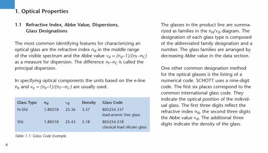
1.1 Refractive Index, Abbe Value, Dispersions, Glass Designations
The most common identifying features for characterizing anoptical glass are the refractive index nd in the middle range of the visible spectrum and the Abbe value nd = (nd–1)/(nF–nC)as a measure for dispersion. The difference nF–nC is called theprincipal dispersion.
In specifying optical components the units based on the e-linene and ne = (ne–1)/(nF'–nC') are usually used.
The glasses in the product line are summa-rized as families in the nd/nd diagram. Thedesignation of each glass type is composedof the abbreviated family designation and anumber. The glass families are arranged bydecreasing Abbe value in the data section.
One other common designation methodfor the optical glasses is the listing of anumerical code. SCHOTT uses a nine-digitcode. The first six places correspond to thecommon international glass code. Theyindicate the optical position of the individ-ual glass. The first three digits reflect therefractive index nd, the second three digitsthe Abbe value nd. The additional threedigits indicate the density of the glass.
6
1. Optical Properties
Glass Type nd nd Density Glass Code
N-SF6 1.80518 25.36 3.37 805254.337lead-arsenic free glass
SF6 1.80518 25.43 5.18 805254.518classical lead silicate glass
Table 1.1: Glass Code Example.
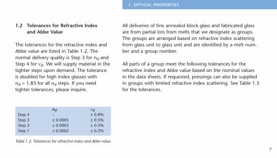
1.2 Tolerances for Refractive Index and Abbe Value
The tolerances for the refractive index andAbbe value are listed in Table 1.2. Thenormal delivery quality is Step 3 for nd andStep 4 for nd. We will supply material in thetighter steps upon demand. The toleranceis doubled for high index glasses with nd > 1.83 for all nd steps. If you needtighter tolerances, please inquire.
7
1. OPTICAL PROPERTIES
nd ndStep 4 – ± 0.8%Step 3 ± 0.0005 ± 0.5%Step 2 ± 0.0003 ± 0.3%Step 1 ± 0.0002 ± 0.2%
Table 1.2: Tolerances for refractive index and Abbe value.
All deliveries of fine annealed block glass and fabricated glassare from partial lots from melts that we designate as groups.The groups are arranged based on refractive index scatteringfrom glass unit to glass unit and are identified by a melt num-ber and a group number.
All parts of a group meet the following tolerances for therefractive index and Abbe value based on the nominal values in the data sheets. If requested, pressings can also be suppliedin groups with limited refractive index scattering. See Table 1.3for the tolerances.
1.3 Test Certificates for Refractive Indices and Dispersions
1.3.1 Standard Test Certificates
We provide standard test certificates for all deliveries of fineannealed optical glass. The information they contain refers tothe average position of the optical values of a group, which isidentified by its melt number and group number. The value ofthe individual parts may deviate by the scattering tolerance ofthe information.
8
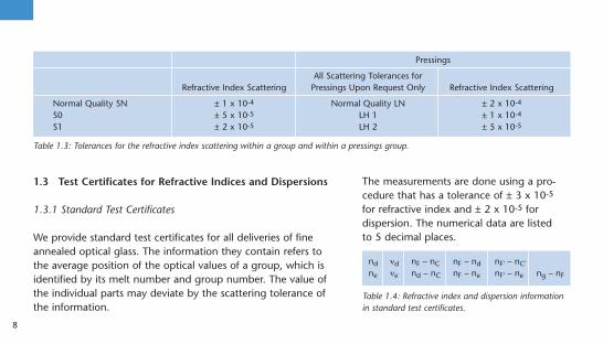
Table 1.3: Tolerances for the refractive index scattering within a group and within a pressings group.
Pressings
All Scattering Tolerances for Refractive Index Scattering Pressings Upon Request Only Refractive Index Scattering
Normal Quality SN ± 1 x 10⁻⁴ Normal Quality LN ± 2 x 10⁻⁴
S0 ± 5 x 10⁻⁵ LH 1 ± 1 x 10⁻⁴
S1 ± 2 x 10⁻⁵ LH 2 ± 5 x 10⁻⁵
The measurements are done using a pro-cedure that has a tolerance of ± 3 x 10⁻⁵
for refractive index and ± 2 x 10⁻⁵ fordispersion. The numerical data are listed to 5 decimal places.
nd nd nF – nC nF – nd nF' – nC'ne ne nd – nC nF – ne nF' – ne ng – nF
Table 1.4: Refractive index and dispersion informationin standard test certificates.
Test certificates with higher accuracy can be prepared for individual glass parts uponrequest (± 2 x 10⁻⁵ for refractive index and± 1 x 10⁻⁵ for dispersion).
1.3.2 Precision Test Certificates VIS, UV – IRand Super Precision Test Certificates VIS
These test certificates are issued uponrequest. They generally refer to individualglass parts.The precision test certificates VIS for thevisible spectral range contain the same dataas the test certificates for standard accuracy,but the dispersion data are given to 6 deci-mal places. The values apply for an airpressure of 0.10133 x 10⁶ Pa. The mea-surement is done on a prism goniometer.
The accuracy is ± 1 x 10⁻⁵ for refractive index and ± 3 x 10⁻⁶
for dispersion.
With an increased sample and measurement cost the refractiveindices can be determined to an accuracy of ± 5 x 10⁻⁶ and thedispersion to ± 2 x 10⁻⁶ if there is sufficient transmittance in thespectral range between 0.405 µm and 0.656 µm. The measure-ment results are listed on a test certificate with super precisionaccuracy.
The precision test certificates UV – IR contain additional refrac-tive index data for an expanded spectral range, which spans amaximum range of 248 nm to 2325 nm.
The accuracy of the refractive indices is better than ± 1 x 10⁻⁵.In the infrared range above 2 µm it is ± 2 x 10⁻⁵. The constantsof the Sellmeier dispersion formula are also listed for the appli-cable spectral range from a complete measurement series.
9
1. OPTICAL PROPERTIES
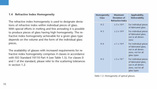
1.4 Refractive Index Homogeneity
The refractive index homogeneity is used to designate devia-tions of refractive index within individual pieces of glass.With special efforts in melting and fine annealing it is possibleto produce pieces of glass having high homogeneity. The re-fractive index homogeneity achievable for a given glass typedepends on the volume and the form of the individual glasspieces.
The availability of glasses with increased requirements for re-fractive index homogeneity comprises 4 classes in accordancewith ISO Standard 10110 Part 4 (see Table 1.5). For classes 0and 1 of the standard, please refer to the scattering tolerancesin section 1.2.
10
Homogeneity Maximum Applicability,Class Deviation of Deliverability
Refractive Index
H 2 ± 5 x 10⁻⁶ For individual piecesof fabricated glass
H 3 ± 2 x 10⁻⁶ For individual piecesof fabricated glass,not in all dimen-sions
H 4 ± 1 x 10⁻⁶ For individual piecesof fabricated glass,not in all dimen-sions, not for allglass types
H 5 ± 5 x 10⁻⁷ For individual piecesof fabricated glass,not in all dimen-sions, not for allglass types
Table 1.5: Homogeneity of optical glasses.
1.5 Internal Transmittance, Color Code
The internal transmittance, i. e. the lighttransmission excluding reflection losses, isclosely related to the optical position of theglass type according to general dispersiontheory. Using the purest raw materials andcostly melting technology it is possible toapproach the dispersion limits for internaltransmittance in the short wave spectralrange.
SCHOTT seeks to achieve the best possibleinternal transmittance. Due to the laws ofeconomics, however, slight deviations inthe purity of the raw materials must betaken into account. SCHOTT maintains a
minimum standard for the related deviations in internal trans-mittance of the glasses melted.
The information in the data section comprises average valuesfrom several melts of a glass type.Upon special request minimum values for internal transmittancecan be maintained. Prior clarification of the delivery situation isrequired.
The internal transmittance of lead- and arsenic-free glasses, inwhich lead has been replaced by other chemical elements, ismarkedly less than in the lead-containing predecessor glasses. In the case of high requirements for internal transmittance inthe violet and ultraviolet spectral range, the classical glasses thatremain in the product line may be used.The internal transmittance at 400 nm for a sample thickness of25 mm is listed in the data section.
11
1. OPTICAL PROPERTIES
The limit of the transmission ranges of optical glasses towardsthe UV area is of special interest in high index glasses because,with increasing refractive index, shift closer to the visible spec-tral range. A simple description of the position and slope of theUV absorption curve is described by the color code.
The color code lists the wavelengths l80 and l5, at which thetransmission (including reflection losses) is 0.80 and 0.05 at 10 mm thickness. The values are rounded to 10 nm and arenoted by eliminating the one position. Color code 33/30 means,for example l80 = 330 nm and l5 = 300 nm.
12
2.1 Striae
Deviations of the refractive index in glass ofshort range are called striae. They resemblebands in which the refractive index deviateswith a typical period of tenths to severalmillimeters.
The recently released standard ISO 10110Part 4 contains a classification with referenceto striae. Since it refers to finished opticalcomponents, however, it is only condition-ally applicable to optical glass in its usualforms of supply. It evaluates the striae intoclasses 1–4 according to their area basedon the optically effective total surface of thecomponent. In so doing, it only considersstriae that deform an even wavefront bymore than 30 nm.
The fifth class identifies glass with extreme freedom from striae.It also includes striae below 30 nm wavefront distortion, butdirects the user to make arrangements with the glass manufac-turer.
The production formats of all optical glasses from SCHOTT meet the requirements of classes 1 – 4 of ISO 10110 Part 4. The tested glass thickness is normally much larger than that of the finished optical components. The effective striae qualityin the optical system is therefore much better.
SCHOTT generally uses the shadow graph method to test alloptical glasses. The high sensitivity of the method is sufficient to characterize the glass, even for the most stringent require-ments.
Quality step VS1, increased striae selection, identifies glass withespecially high requirements. Glass in this step contains nostriae determinable with the shadow method. For prism appli-
13
2. INTERNAL PROPERTIES
2. Internal Properties

cations SCHOTT offers quality step VS2. Such glass parts meetthe requirements of step VS1 in two directions perpendicular toone another.
2.2 Bubbles and Inclusions
The optical glasses exhibit remarkable freedom from bubbles.Bubbles in glass cannot, however, be completely avoided due tothe often complicated glass compositions and manufacturingprocesses.
The characterization of the bubble content of a glass is done byreporting the total cross section in mm2 of a glass volume of100 cm3, calculated from the sum of the detected cross sectionof bubbles. Inclusions in glass, such as stones or crystals aretreated like bubbles of the same cross section. The evaluationconsiders all bubbles and inclusions ³ 0.03 mm.
14
The bubble classes and the maximum allow-able quantities and diameters of bubblesand inclusions are listed in Table 2.1. In the increased quality steps VB (increasedbubble selection) and EVB (extra increasedbubble selection) the glasses can only besupplied as fabricated pieces of glass.In accordance with ISO 10110 Part 3,bubbles may be distributed. Instead of abubble with a given dimension, a largerquantity of bubbles of smaller dimensions is allowable.

15
2. INTERNAL PROPERTIES
Bubble Class According to Catalog Data Sheet of the Con- B0 B0 B0 B1 B1 B1cerned Glass Type Quality Step VB EVB VB EVB
Maximum allowable cross section of all bubbles and inclusions in mm2 per 100 cm3 of glass volume 0.03 0.01 0.006 0.1 0.03 0.02
Maximum allowable quantity per 100 cm3 10 4 2 30 10 4
Maximum allowable 50 0.10 0.10 0.10 0.15 0.15 0.10diameter of bubbles or 100 0.15 0.15 0.10 0.20 0.15 0.10inclusions in mm1) 200 0.20 0.15 0.10 0.30 0.20 0.10
300 0.25 0.20 – 0.40 0.25 –500 0.40 – – 0.60 – –800 0.55 – – 0.80 – –
1) Note: In the strip and block forms of supply from which much smaller finished parts are usually produced, occasional, isolated bubbles with larger diameters are allowed if the limit values for the total cross section and quantity per volume are maintained.
Table 2.1: Tolerances for bubbles and inclusions in optical glasses.
Special applications, such as in high energylasers, in Color Cubes or as streak imagingcameras and high pitch gratings, allow onlyglasses that have a low quantity of verysmall bubbles/inclusions. We can offerglasses that meet these requirements uponrequest.
2.3 Stress Birefringence
The size and distribution of permanent inherent stresses inglasses depends on the annealing conditions (for example, an-nealing speed and temperature distribution around the object be-ing annealed), the glass type, and the dimensions. The stressescause birefringence that is dependent upon the glass type.
Stress birefringence is measured as a path difference using thede Sénarmont and Friedel Method and is listed in nm/cm basedon the test thickness. Its accuracy is 3 – 5 nm for simple geomet-ric test sample forms. The measurement is done on round discsat a distance of 5% of the diameter from the edge. For rectan-gular plates the measurement is performed in the center of thelonger side at a distance of 5% of the plate width. A detaileddescription of the method can be found in ISO Standard 11455.
16
The de Sénarmont and Friedel Method isinsufficient for measurements of low stressbirefringence and low thickness. In thesecases we have methods that we can use tomeasure an order of magnitude more accu-rately.
With our annealing methods we are able to achieve both good optical homogeneityand very low stress birefringence values.Pieces of glass to be delivered generallyhave a symmetrical stress distribution. Theglass surface is usually in compression.
The limit values for stress birefringence inparts larger than 600 mm are availableupon request.

Higher stresses are permitted in glass to be hot processed, but they may not limitmechanical processing.
17
2. INTERNAL PROPERTIES
Stress Birefringence
Dimensions Fine Annealing Special Annealing Precision Annealing[nm/cm] (SK) [nm/cm] (SSK) [nm/cm]
Ø ² 300 mmd ² 60 mm ² 10 ² 6 ² 4
Ø > 300–600 mmd > 60–80 mm ² 12 ² 6 ² 4
Table 2.2: Limit values of stress birefringence in processed glasses for variousdimensions.

3.1 Standard Delivery Performance
If no special quality steps are requested, the glass will be de-livered in refractive index/Abbe value step 3/4 with a standardtest certificate. The standard test certificate refers to a refractiveindex group that is identified by its melt number and groupnumber. The refractive indices of all parts belonging to a groupwill not deviate by more than ± 1 x 10⁻⁴ (± 2 x 10⁻⁴ forpressings, if requested). The glass is tested for bubbles andinclusions, striae, and stress birefringence.
18
3. Delivery Performance
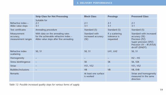
3.2 Increased Delivery Performance
The entire range of increased quality steps cannot be offered for all forms ofsupply. For information on this, refer to the following table.
19
3. DELIVERY PERFORMANCE
Strip Glass for Hot Processing Block Glass Pressings Processed Glass
Suitable forRefractive index – 2-1 2-1 2-1 2-1Abbe value steps 3-1 3-1 3-1 3-1
Test certificates Annealing procedure Standard (S) Standard (S) Standard (S)
Measurement With data on the annealing rates Standard with If a scattering Standard with increasedaccuracy, for the achievable refractive index – increased accuracy tolerance is accuracy (SE)measurement ranges Abbe value steps after fine annealing (SE) requested Precision (PZ)
Super precision (SPZ)Precision UV – IR (PZUI)dn/dT (DNDT)
Refractive index S0, S1 S0, S1 LH1, LH2 S0, S1scattering
Homogeneity – – – H2 – H5
Stress birefringence – SK SK SK, SSK
Striae – VS1, VS2 – VS1, VS2
Bubbles/inclusions – VB VB VB, EVB
Remarks At least one surface Striae and homogeneity is worked measured in the same
direction
Table 12: Possible increased quality steps for various forms of supply.

20
The quality steps listed within a form of supply can becombined with one another. However, melts suitable for various combinations are not always available.
We recommend that you check availability with us as soon as possible.Requirements that exceed the mentioned quality steps may also be met. Please inquire about availability.
4.1 Raw Glass
4.1.1 Blocks
Blocks have five unworked, as-cast surfaces.At least one surface is worked as a rule. The edges are rounded.Blocks are fine annealed and thereforesuitable for cold working.Described by: length, width, thickness
4.1.2 Strips
Strips have unworked surfaces and brokenor cut ends.Strips are coarse annealed and therefore areonly suitable for hot working.Described by: length, width, thickness
4.2 Fabricated Glass
4.2.1 Plates
Plates are quadrilateral, fabricated parts. All six sides are worked;the edges have protective bevels.Described by: length, width, thickness
21
4. FORMS OF SUPPLY AND TOLERANCES
4. Forms of Supply and Tolerances

22
Greatest Edge Allowable Tolerances Minimum Length Thickness1)
[mm] For edge length For thickness [mm]
Standard [mm] VAT2) Standard [mm] VAT2)
> 3–80 ± 0.2 ± 0.1 ± 0.3 ± 0.15 2> 80–120 ± 0.3 ± 0.15 ± 0.5 ± 0.25 4> 120–250 ± 0.5 ± 0.25 ± 0.5 ± 0.25 6> 250–315 ± 0.9 ± 0.45 ± 0.8 ± 0.4 8> 315–400 ± 1.2 ± 0.6 ± 0.8 ± 0.4 8> 400–500 ± 1.3 ± 0.65 ± 0.8 ± 0.4 20
> 500–630 ± 1.5 ± 0.75 ± 0.8 ± 0.4 20> 630–800 ± 1.8 ± 0.9 ± 0.8 ± 0.4 20> 800–1000 ± 2.0 ± 1.0 ± 0.8 ± 0.4 20
> 1000 Inquire Inquire Inquire Inquire
Table 13: Dimensional tolerances and minimum dimensions for plates.
1) Lower thicknesses than listed are possible. Please inquire.2) VAT = closer dimensional tolerances.
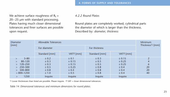
Diameter Allowable Tolerances Minimum[mm] Thickness1) [mm]
For diameter For thickness
Standard [mm] VAT2) [mm] Standard [mm] VAT2) [mm]
> 3–80 ± 0.2 ± 0.1 ± 0.3 ± 0.15 2> 80–120 ± 0.3 ± 0.15 ± 0.5 ± 0.25 4> 120–250 ± 0.3 ± 0.15 ± 0.5 ± 0.25 6> 250–500 ± 0.5 ± 0.25 ± 0.8 ± 0.4 20> 500–800 ± 0.8 ± 0.4 ± 0.8 ± 0.4 20> 800–1250 ± 1.0 ± 0.5 ± 0.8 ± 0.4 40> 1250 Inquire Inquire Inquire Inquire
We achieve surface roughness of Rt =20– 25 µm with standard processing.Plates having much closer dimensionaltolerances and finer surfaces are possibleupon request.
4.2.2 Round Plates
Round plates are completely worked; cylindrical parts the diameter of which is larger than the thickness.Described by: diameter, thickness
23
4. FORMS OF SUPPLY AND TOLERANCES
Table 14: Dimensional tolerances and minimum dimensions for round plates.
1) Lower thicknesses than listed are possible. Please inquire. 2) VAT = closer dimensional tolerances.
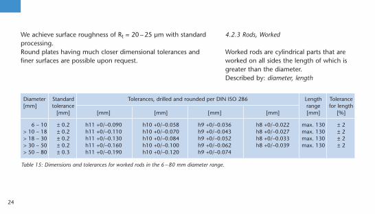
We achieve surface roughness of Rt = 20 – 25 µm with standardprocessing.Round plates having much closer dimensional tolerances andfiner surfaces are possible upon request.
4.2.3 Rods, Worked
Worked rods are cylindrical parts that areworked on all sides the length of which isgreater than the diameter.Described by: diameter, length
24
Diameter Standard Tolerances, drilled and rounded per DIN ISO 286 Length Tolerance[mm] tolerance range for length
[mm] [mm] [mm] [mm] [mm] [mm] [%]
6 – 10 ± 0.2 h11 +0/–0.090 h10 +0/–0.058 h9 +0/–0.036 h8 +0/–0.022 max. 130 ± 2> 10 – 18 ± 0.2 h11 +0/–0.110 h10 +0/–0.070 h9 +0/–0.043 h8 +0/–0.027 max. 130 ± 2> 18 – 30 ± 0.2 h11 +0/–0.130 h10 +0/–0.084 h9 +0/–0.052 h8 +0/–0.033 max. 130 ± 2> 30 – 50 ± 0.2 h11 +0/–0.160 h10 +0/–0.100 h9 +0/–0.062 h8 +0/–0.039 max. 130 ± 2> 50 – 80 ± 0.3 h11 +0/–0.190 h10 +0/–0.120 h9 +0/–0.074
Table 15: Dimensions and tolerances for worked rods in the 6 – 80 mm diameter range.
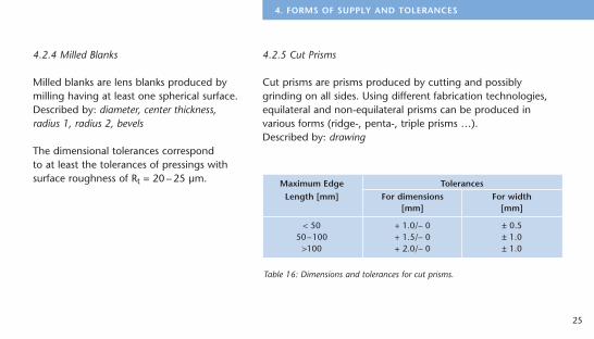
4.2.4 Milled Blanks
Milled blanks are lens blanks produced bymilling having at least one spherical surface.Described by: diameter, center thickness,radius 1, radius 2, bevels
The dimensional tolerances correspond to at least the tolerances of pressings withsurface roughness of Rt = 20 – 25 µm.
25
4. FORMS OF SUPPLY AND TOLERANCES
Maximum Edge TolerancesLength [mm] For dimensions For width
[mm] [mm]
< 50 + 1.0/– 0 ± 0.550–100 + 1.5/– 0 ± 1.0
>100 + 2.0/– 0 ± 1.0
Table 16: Dimensions and tolerances for cut prisms.
4.2.5 Cut Prisms
Cut prisms are prisms produced by cutting and possiblygrinding on all sides. Using different fabrication technologies,equilateral and non-equilateral prisms can be produced invarious forms (ridge-, penta-, triple prisms …).Described by: drawing
26
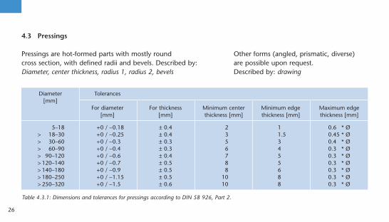
4.3 Pressings
Pressings are hot-formed parts with mostly round cross section, with defined radii and bevels. Described by:Diameter, center thickness, radius 1, radius 2, bevels
Diameter Tolerances[mm]
For diameter For thickness Minimum center Minimum edge Maximum edge[mm] [mm] thickness [mm] thickness [mm] thickness [mm]
5–18 +0 / –0.18 ± 0.4 2 1 0.6 * Ø> 18–30 +0 / –0.25 ± 0.4 3 1.5 0.45 * Ø> 30–60 +0 / –0.3 ± 0.3 5 3 0.4 * Ø> 60–90 +0 / –0.4 ± 0.3 6 4 0.3 * Ø> 90–120 +0 / –0.6 ± 0.4 7 5 0.3 * Ø> 120–140 +0 / –0.7 ± 0.5 8 5 0.3 * Ø> 140–180 +0 / –0.9 ± 0.5 8 6 0.3 * Ø> 180–250 +0 / –1.15 ± 0.5 10 8 0.3 * Ø> 250–320 +0 / –1.5 ± 0.6 10 8 0.3 * Ø
Table 4.3.1: Dimensions and tolerances for pressings according to DIN 58 926, Part 2.
Other forms (angled, prismatic, diverse) are possible upon request. Described by: drawing
For this information we refer you to our catalog on CD-ROMthat contains detailed information on the subject.
Chapter 9 of this pocket catalog contains a selection of usefulformulas.
27
5. OPTICAL PROPERTIES, THEORETICAL EXPLANATIONS
5. Optical Properties, Theoretical Explanations
Depending on the quantity and dimensionsof the part, production of direct pressingsmay make economic sense. We will discussspecifications upon request.

After an exposure time of 30 hours the glass-es are removed from the climatic chamber.The difference DH between the haze beforeand after testing is used as a measure of theresulting surface change. The measurementsare conducted using a spherical hazemeter.The classifications are done based on theincrease in transmission haze DH after a 30-hour test period.
The glasses in class CR 1 display no visibleattack after being subjected to 30 hours ofclimatic change. In normal humidity condi-tions during the fabrication and storing ofoptical glasses in class CR 1, no surfaceattack should be expected. On the otherhand, the fabrication and storing of opticalglasses in class CR 4 should be done with
28
6. Chemical Properties
The five test methods described below are used to assess thechemical behavior of polished glass surfaces.
6.1 Climatic Resistance (ISO/WD 13384), Distribution into Climatic Resistance Classes CR 1 – 4
Climatic resistance describes the behavior of optical glasses athigh relative humidity and high temperatures. In sensitive glass-es a cloudy film can appear that generally cannot be wiped off.
An accelerated procedure is used to test the climatic resistanceof the glasses, in which polished, uncoated glass plates are sub-jected to a water vapor saturated atmosphere, the temperatureof which is alternated between 40°C and 50°C. This produces aperiodical change from moist condensation on the glass surfaceand subsequent drying.
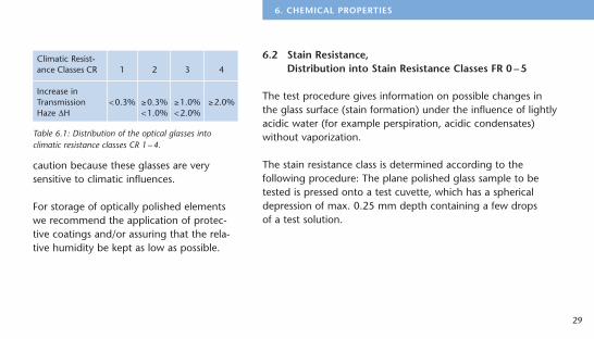
6.2 Stain Resistance, Distribution into Stain Resistance Classes FR 0 – 5
The test procedure gives information on possible changes in the glass surface (stain formation) under the influence of lightlyacidic water (for example perspiration, acidic condensates)without vaporization.
The stain resistance class is determined according to thefollowing procedure: The plane polished glass sample to be tested is pressed onto a test cuvette, which has a sphericaldepression of max. 0.25 mm depth containing a few drops of a test solution.
29
6. CHEMICAL PROPERTIES
Climatic Resist-ance Classes CR 1 2 3 4
Increase inTransmission <0.3% ³0.3% ³1.0% ³2.0%Haze DH <1.0% <2.0%
Table 6.1: Distribution of the optical glasses intoclimatic resistance classes CR 1– 4.
caution because these glasses are verysensitive to climatic influences.
For storage of optically polished elementswe recommend the application of protec-tive coatings and/or assuring that the rela-tive humidity be kept as low as possible.
Stain resistance class FR 0 contains allglasses that exhibit virtually no interferencecolors, even after 100 hours of exposure totest solution I.Glasses in classification FR 5 must be han-dled with particular care during processing.
6.3 Acid Resistance (ISO 8424: 1987),Distribution into Acid ResistanceClasses SR 1 – 4, 5, 51 – 53
Acid resistance classifies the behavior ofoptical glasses that come in contact withlarge quantities of acidic solutions (from apractical standpoint for example, perspira-tion, laminating substances, carbonatedwater, etc.).
30
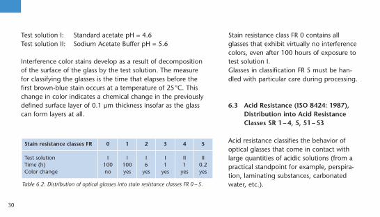
Test solution I: Standard acetate pH = 4.6Test solution II: Sodium Acetate Buffer pH = 5.6
Interference color stains develop as a result of decomposition of the surface of the glass by the test solution. The measure for classifying the glasses is the time that elapses before the first brown-blue stain occurs at a temperature of 25°C. Thischange in color indicates a chemical change in the previouslydefined surface layer of 0.1 µm thickness insofar as the glass can form layers at all.
Stain resistance classes FR 0 1 2 3 4 5
Test solution I I I I II IITime (h) 100 100 6 1 1 0.2Color change no yes yes yes yes yes
Table 6.2: Distribution of optical glasses into stain resistance classes FR 0 – 5.
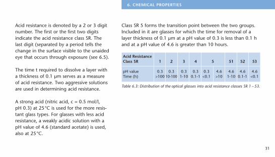
Acid resistance is denoted by a 2 or 3 digitnumber. The first or the first two digits indicate the acid resistance class SR. Thelast digit (separated by a period tells thechange in the surface visible to the unaidedeye that occurs through exposure (see 6.5).
The time t required to dissolve a layer witha thickness of 0.1 µm serves as a measureof acid resistance. Two aggressive solutionsare used in determining acid resistance.
A strong acid (nitric acid, c = 0.5 mol/l, pH 0.3) at 25°C is used for the more resis-tant glass types. For glasses with less acidresistance, a weakly acidic solution with apH value of 4.6 (standard acetate) is used,also at 25°C.
Class SR 5 forms the transition point between the two groups.Included in it are glasses for which the time for removal of alayer thickness of 0.1 µm at a pH value of 0.3 is less than 0.1 hand at a pH value of 4.6 is greater than 10 hours.
31
6. CHEMICAL PROPERTIES
Acid ResistanceClass SR 1 2 3 4 5 51 52 53
pH value 0.3 0.3 0.3 0.3 0.3 4.6 4.6 4.6 4.6Time (h) >100 10-100 1-10 0.1-1 <0.1 >10 1-10 0.1-1 <0.1
Table 6.3: Distribution of the optical glasses into acid resistance classes SR 1 – 53.

6.4 Alkali Resistance (ISO 10629), Distribution into Alkali Resistance Classes AR 1–4 Phosphate Resistance (ISO 9689), Distribution into Phosphate Resistance Classes PR 1–4
Both test methods serve to show the resistance to aqueousalkaline solution in excess and use the same classificationscheme.
The alkali resistance indicates the sensitivity of optical glasses in contact with warm, alkaline liquids, such as cooling liquids ingrinding and polishing processes.The phosphate resistance describes the behavior of opticalglasses during cleaning with phosphate containing washingsolutions (detergents).
The alkali and phosphate resistance is denoted using two digits separated by a decimal point. The first digit lists the alkali resistance class AR or the phosphate resistance class PR,
and the decimal indicates the surfacechanges visible to the unaided eye thatoccur through exposure.
The alkali resistance class AR is based on thetime required to remove a layer thickness of glass of 0.1 µm in an alkaline solution(sodium hydroxide, c = 0.01 mol/l, pH = 12)at a temperature of 50°C.
The phosphate resistance class PR is basedon the time required to remove a layerthickness of glass of 0.1 mm in an alkalinephosphate containing solution (penta-sodium triphosphate Na5P3O10, c = 0.01mol/l, pH = 10) at a temperature of 50°C.
32

The layer thickness is calculated from theweight loss per surface area and the densityof the glass.
.0 no visible changes
.1 clear, but irregular surface
.2 interference colors (light, selective leaching)
.3 firmly adhered thin white layer (stronger, selective leaching,cloudy surface)
.4 loosely adhering, thicker layers, for example, insolublereaction products on the surface (this can be a projectingand/or flaking crust or a projecting surface; strong attack)
6.6 Addendum
Our glasses contain no more than 0.05 weight percent thorium oxide or other radioactive material. Negligible inherent radioactivity can be present in many everydaysubstances as a result of the natural radioactivity of rawmaterials.
33
6. CHEMICAL PROPERTIES
Alkali Resistance 1 2 3 4Classes ARPhosphate ResistanceClasses PR
Time (h) > 4 1–4 0.25–1 < 0.25
Table 6.4: Distribution of the optical glasses in alkaliresistance classes AR 1– 4 and phosphate resistanceclasses PR 1– 4.
6.5 Identification of Visible SurfaceChanges
Meaning of the digits behind the classi-fication for acid, alkali, and phosphateresistance:
7.1 Knoop Hardness
The Knoop hardness of a material is a measure for residualsurface changes after the application of pressure with a testdiamond. The standard ISO 9385 describes the measurementprocedure for glasses. In accordance with this standard, thevalues for Knoop hardness HK are listed in the data sheets for atest force of 0.9807 N (corresponds to 0.1 kp) and an effectivetest period of 20 s. The test was performed on polished glasssurfaces at room temperature. The data for hardness values arerounded to 10 HK 0.1/20. The microhardness is a function ofthe magnitude of the test force and decreases with increasingtest force.
7.2 Grindability with Diamond ParticlesAccording to ISO DFIS 12844
The grindability according to ISO 12844allows the comparison of the grindingprocess of different glasses to one another.Twenty samples of the glass to be classifiedare ground for 30 seconds in a standardizeddiamond pellet tool under predeterminedconditions. Then the samples are comparedby weighing the samples and consideringthe density of the removed volume of the glass with that of a reference glass, N-SK 16.
34
7. Mechanical Properties
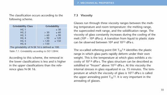
The classification occurs according to thefollowing scheme.
According to this scheme, the removal inthe lower classifications is less and is higherin the upper classifications than the refe-rence glass N-SK 16.
7.3 Viscosity
Glasses run through three viscosity ranges between the melt-ing temperature and room temperature: the melting range, the supercooled melt range, and the solidification range. Theviscosity of glass constantly increases during the cooling of themelt (100 – 104 dPa·s). A transition from liquid to plastic statecan be observed between 104 and 1013 dPa·s.
The so-called softening point EW T107.6 identifies the plasticrange in which glass parts rapidly deform under their ownweight. This is the temperature at which glass exhibits a vis-cosity of 107.6 dPa·s. The glass structure can be described assolidified or “frozen” above 1013 dPa·s. At this viscosity theinternal stresses in glass equalized in ca. 15 minutes. The tem-perature at which the viscosity of glass is 1013 dPa·s is called the upper annealing point T1013. It is very important in theannealing of glasses.
35
7. MECHANICAL PROPERTIES
Grindability Class GrindabilityHG 1 ² 30HG 2 > 30 ² 60HG 3 > 60 ² 90HG 4 > 90 ² 120HG 5 > 120 ² 150HG 6 > 150
The grindability of N-SK 16 is defined as 100.
Table 7.1: Grindability according to ISO 12844.
Another possibility for identifying the transformation range is the change in the rate of relative linear thermal expansion. In accordance with ISO 7884-8, this can be used to determinethe so-called transformation temperature Tg. It generally liesright at T1013.
Precision optical surfaces may deform and refractive indices may change if a temperature of T1013 – 200 K is exceededduring any thermal treatment.
7.4 Coefficient of Linear Thermal Expansion
The typical curve of the linear thermal expansion of glasses at an absolute zero point begins with an obvious increase inslope to approximately room temperature. Then a nearly linearincrease to the beginning of the noticeable plastic behaviorfollows. The transformation range is distinguished by a distinctbending of the expansion curve that results from the increasing
structural movement in the glass. Abovethis range the expansion again exhibits anearly linear increase, but with a noticeablygreater rate of increase.
Due to the dependence of the coefficient oflinear thermal expansion a on temperature,two average linear thermal expansion coef-ficients a are usually given for the followingtemperature ranges:
a(–30°C; +70°C) as the relevant informati-on for room temperature (listed in the datasheets)a(20°C; +300°C) as the standard interna-tional value for comparison purposes andfor orientation during melting processesand temperature change loading (see thedata sheet in the CD-ROM catalog).
36
8.1 Thermal Conductivity
The range of values for thermal conduc-tivity for glasses at room temperatureextends from 1.38 W/(m·K) (pure quartzglass) to about 0.5 W/(m·K) (high leadcontaining glasses). The most commonlyused silicate glasses have values between0.9 and 1.2 W/(m·K).
The thermal conductivities shown in thedata sheets apply for a glass temperature of 90°C; the degree of accuracy is ±5%.
8.2 Specific Thermal Capacity
The mean isobaric specific heat capacity cr (20°C; 100°C) islisted for a portion of the glasses as measured from the heattransfer of a hot glass at 100°C in a liquid calorimeter at 20°C.The range of values for cr (20°C; 100°C) and also for the truethermal capacity cr (20°C) for silicate glasses is between 0.42and 0.84 J/(g·K).
The data on thermal properties are contained in the CD-ROMcatalog.
37
8. THERMAL PROPERTIES
8. Thermal Properties
Relative Partial Dispersion Px, y for the wavelengths x and y based on the blue F and red C hydrogen linePx, y = (nx – ny) / (nF – nC) (9.1)
or based on the blue F’ and red C’ cadmium lineP‘x, y = (nx – ny) / (nF‘ – nC‘) (9.2)
Linear relationship between the Abbe value and the relative partial dispersion for “normal glasses”Px, y » axy + bxy · nd (9.3)
Deviation DP from the “normal lines”Px, y = axy + bxy · nd + DPx, y (9.4)DPC, t = (nC – nt) / (nF – nC) – (0,5450 + 0,004743 · nd) (9.5)DPC, s = (nC – ns) / (nF – nC) – (0,4029 + 0,002331 · nd) (9.6)DPF, e = (nF – ne) / (nF – nC) – (0,4884 – 0,000526 · nd) (9.7)DPg, F = (ng – nF) / (nF – nC) – (0,6438 – 0,001682 · nd) (9.8)DPi, g = (ni – ng) / (nF – nC) – (1,7241 – 0,008382 · nd) (9.9)
The position of the normal lines was determined based on value pairs of glass types K 7 and F 2.
38
9. Collection of Formulas and Wavelength Table
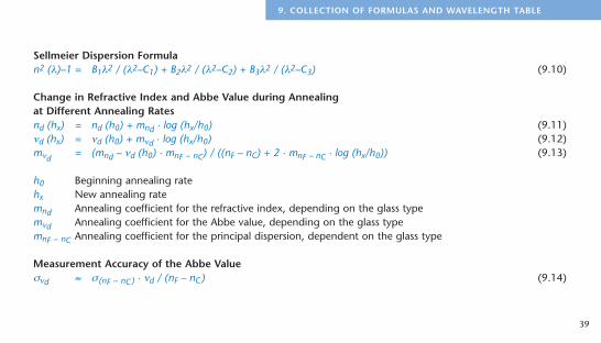
Sellmeier Dispersion Formulan2 (l)–1 = B1l2 / (l2–C1) + B2l2 / (l2–C2) + B3l2 / (l2–C3) (9.10)
Change in Refractive Index and Abbe Value during Annealing at Different Annealing Ratesnd (hx) = nd (h0) + mnd · log (hx/h0) (9.11)nd (hx) = nd (h0) + mnd · log (hx/h0) (9.12)mnd
= (mnd – nd (h0) · mnF – nC) / ((nF – nC) + 2 · mnF – nC · log (hx/h0)) (9.13)
h0 Beginning annealing rate hx New annealing ratemnd Annealing coefficient for the refractive index, depending on the glass typemnd Annealing coefficient for the Abbe value, depending on the glass typemnF – nC Annealing coefficient for the principal dispersion, dependent on the glass type
Measurement Accuracy of the Abbe Valuesnd » s (nF – nC) · nd / (nF – nC) (9.14)
39
9. COLLECTION OF FORMULAS AND WAVELENGTH TABLE
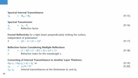
Spectral Internal Transmittancetil = Fel / Fil (9.15)
Spectral Transmissiontl = til · Pl (9.16)Pl Reflection factor
Fresnel Reflectivity for a light beam perpendicularly striking the surface, independent of polarizationR = ((n – 1) / (n + 1))2 (9.17)
Reflection Factor Considering Multiple ReflectionsP = (1 – R)2 / (1 – R2) = 2n / (n2 + 1) (9.18)n Refractive index for the wavelength l.
Converting of Internal Transmittance to Another Layer Thicknesslog ti1 / log ti2 = d1 / d2 or (9.19)ti2 = ti1(d2 / d1) (9.20)ti2, ti1 Internal transmittances at the thicknesses d1 and d2
40
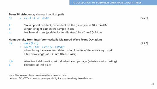
Stress Birefringence, change in optical pathDs = 10 · K · d · s in nm (9.21)
K Stress optical constant, dependent on the glass type in 10-6 mm2/Nd Length of light path in the sample in cms Mechanical stress (positive for tensile stress) in N/mm2 (= Mpa)
Homogeneity from Interferometrically Measured Wave Front DeviationsDn = DW / (2 · d) (9.22)
= DW [l] · 633 · 10-6 / (2 · d [mm])when listing the wave front deformation in units of the wavelength and a test wavelength of 633 nm (He-Ne laser)
DW Wave front deformation with double beam passage (interferometric testing)d Thickness of test piece
Note: The formulas have been carefully chosen and listed. However, SCHOTT can assume no responsibility for errors resulting from their use.
41
9. COLLECTION OF FORMULAS AND WAVELENGTH TABLE
42
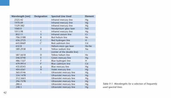
Wavelength [nm] Designation Spectral Line Used Element
2325.42 Infrared mercury line Hg1970.09 Infrared mercury line Hg1529.582 Infrared mercury line Hg1060.0 Neodymium glass laser Nd1013.98 t Infrared mercury line Hg852.11 S Infrared cesium line Cs706.5188 R Red helium line He656.2725 C Red hydrogen line H643.8469 C’ Red cadmium line Cd632.8 Helium-neon gas laser He-Ne589.2938 D Yellow sodium line Na
(center of the double line)587.5618 D Yellow helium line He546.0740 E Green mercury line Hg486.1327 F Blue hydrogen line H479.9914 F’ Blue cadmium line Cd435.8343 g Blue mercury line Hg404.6561 H Violet mercury line Hg365.0146 i Ultraviolet mercury line Hg334.1478 Ultraviolet mercury line Hg312.5663 Ultraviolet mercury line Hg296.7278 Ultraviolet mercury line Hg280.4 Ultraviolet mercury line Hg248.3 Ultraviolet mercury line Hg
Table 9.1: Wavelengths for a selection of frequentlyused spectral lines.

43
10. EXPLANATION OF THE DESIGNATIONS IN THE DATA SECTION
10. Explanation of the Designations in the Data Section
Glass Code – International glass code of refractive index nd and Abbe value nd with densitynx, nx, nx – ny – Refractive index, Abbe value, and dispersion at various wavelengthsCR – Climatic resistance class (ISO/WD 13384)FR – Stain resistance classSR – Acid resistance class (ISO 8424)AR – Alkali resistance class (ISO 10629)PR – Phosphate resistance class (ISO 9689)a – Coefficient of linear thermal expansion a (–30°C; +70°C) in 10-6/K Tg – Transformation temperature in °C (ISO 7884-8)T107,6 – Temperature of the glass at a viscosity of T107.6 dPa sr – Density in g/cm3
HK – Knoop hardness (ISO 9385)HG – Grindability Class (ISO 12844)B – Bubble classti – Internal transmittance at 400 nm; glass thickness: 25 mmColor Code – Wavelengths for transmission 0.80 and 0.05; glass thickness 10 mm (JOGIS)
11.1 Preferred Glasses
The glass types listed in the current product line are preferredglasses. Delivery from stock is generally guaranteed.
11.2 Inquiry Glasses
A stock of inquiry glasses is not maintained. They are producedupon specific customer demand. When ordering, a completemelt must be taken. The minimum melting quantity primarilydepends upon the melting method and the glass type. Delivery times and specifications are individually determinedupon receipt of an order.
11.3 Article Definition
SCHOTT defines an article by glass type,form of supply, dimensions, and quality.
11.4 Preferred and Inquiry ArticlesAll preferred optical glasses in the currentproduct line are represented by at least onepreferred article.
Preferred articles are considered in salesplanning from available data and aretherefore normally always available.
44
11. Logistics
The minimum order quantity for preferredarticles is 1 block or strips, which can beshipped within one week, depending onthe order quantity.
Special articles can be produced from thepreferred articles by fabrication, selection,or quality testing. These customer-specificarticles deviate in form of supply, dimen-sions, or quality from preferred articles andare considered inquiry articles.
Inquiry articles are usually not stocked.They are made for specific customer orders.
45
11. LOGISTICS
11.5 Preferred Product Line
Information on the current preferred product line is containedin the CD-ROM.
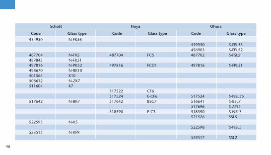
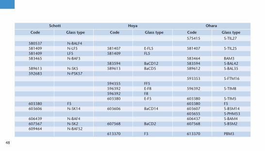
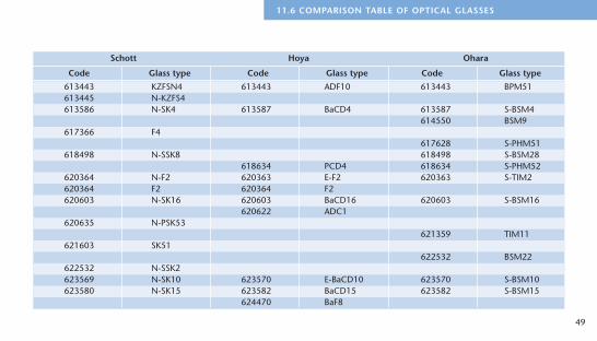
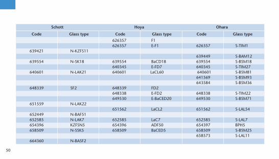
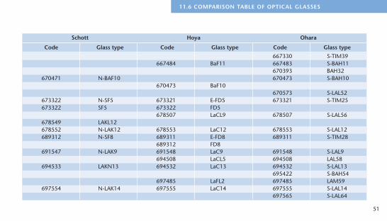
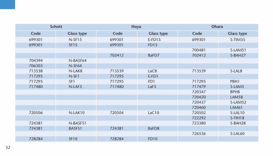
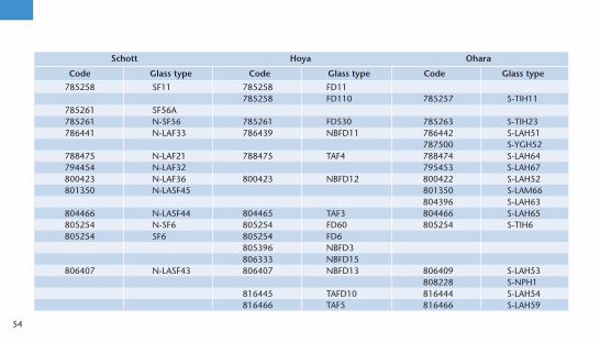
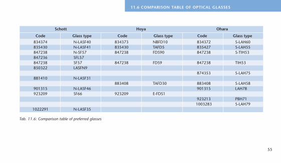
11.6 Comparison Table of Optical Glasses
The following comparison table gives an overview of thepreferred glasses from Schott, Hoya, and Ohara. The glass types are listed in order of increasing refractive index.
Schott Hoya Ohara
Code Glass type Code Glass type Code Glass type
434950 N-FK56439950 S-FPL53456903 S-FPL52
487704 N-FK5 487704 FC5 487702 S-FSL5487845 N-FK51497816 N-PK52 497816 FCD1 497816 S-FPL51498670 N-BK10501564 K10508612 N-ZK7511604 K7
517522 CF6517524 E-CF6 517524 S-NSL36
517642 N-BK7 517642 BSC7 516641 S-BSL7517696 S-APL1
518590 E-C3 518590 S-NSL3521526 SSL5
522595 N-K5522598 S-NSL5
523515 N-KF9529517 SSL2
46

Schott Hoya Ohara
Code Glass type Code Glass type Code Glass type
529770 N-PK51532488 FEL6
532488 N-LLF6 532489 E-FEL6 532489 S-TIL6540597 N-BAK2 540595 S-BAL12
541472 E-FEL2 541472 S-TIL2541472 FEL2
547536 N-BALF5548458 LLF1 548458 FEL1548458 N-LLF1 548458 E-FEL1 548458 S-TIL1
551496 SbF1552635 N-PSK3558542 N-KZFS2
560612 S-BAL50564608 N-SK11 564607 E-BaCD11 564607 S-BAL41
567428 FL6 567428 PBL26569561 N-BAK4 569563 BaC4 569563 S-BAL14569713 N-PSK58
571508 S-BAL2571530 S-BAL3
573576 N-BAK1 573578 S-BAL11
47
11.6 COMPARISON TABLE OF OPTICAL GLASSES
Schott Hoya Ohara
Code Glass type Code Glass type Code Glass type
575415 S-TIL27580537 N-BALF4581409 N-LF5 581407 E-FL5 581407 S-TIL25581409 LF5 581409 FL5583465 N-BAF3 583464 BAM3
583594 BaCD12 583594 S-BAL42589613 N-SK5 589613 BaCD5 589612 S-BAL35592683 N-PSK57
593353 S-FTM16594355 FF5596392 E-F8 596392 S-TIM8596392 F8603380 E-F5 603380 S-TIM5
603380 F5 603380 F5603606 N-SK14 603606 BaCD14 603607 S-BSM14
603655 S-PHM53606439 N-BAF4 606437 S-BAM4607567 N-SK2 607568 BaCD2 607568 S-BSM2609464 N-BAF52
613370 F3 613370 PBM3
48
Schott Hoya Ohara
Code Glass type Code Glass type Code Glass type
613443 KZFSN4 613443 ADF10 613443 BPM51613445 N-KZFS4613586 N-SK4 613587 BaCD4 613587 S-BSM4
614550 BSM9617366 F4
617628 S-PHM51618498 N-SSK8 618498 S-BSM28
618634 PCD4 618634 S-PHM52620364 N-F2 620363 E-F2 620363 S-TIM2620364 F2 620364 F2620603 N-SK16 620603 BaCD16 620603 S-BSM16
620622 ADC1620635 N-PSK53
621359 TIM11621603 SK51
622532 BSM22622532 N-SSK2623569 N-SK10 623570 E-BaCD10 623570 S-BSM10623580 N-SK15 623582 BaCD15 623582 S-BSM15
624470 BaF8
49
11.6 COMPARISON TABLE OF OPTICAL GLASSES
Schott Hoya Ohara
Code Glass type Code Glass type Code Glass type
626357 F1626357 E-F1 626357 S-TIM1
639421 N-KZFS11639449 S-BAM12
639554 N-SK18 639554 BaCD18 639554 S-BSM18640345 E-FD7 640345 S-TIM27
640601 N-LAK21 640601 LaCL60 640601 S-BSM81641569 S-BSM93643584 S-BSM36
648339 SF2 648339 FD2648338 E-FD2 648338 S-TIM22649530 E-BaCED20 649530 S-BSM71
651559 N-LAK22651562 LaCL2 651562 S-LAL54
652449 N-BAF51652585 N-LAK7 652585 LaC7 652585 S-LAL7654396 KZFSN5 654396 ADF50 654397 BPH5658509 N-SSK5 658509 BaCED5 658509 S-BSM25
658573 S-LAL11664360 N-BASF2
50
Schott Hoya Ohara
Code Glass type Code Glass type Code Glass type
667330 S-TIM39667484 BaF11 667483 S-BAH11
670393 BAH32670471 N-BAF10 670473 S-BAH10
670473 BaF10670573 S-LAL52
673322 N-SF5 673321 E-FD5 673321 S-TIM25673322 SF5 673322 FD5
678507 LaCL9 678507 S-LAL56678549 LAKL12678552 N-LAK12 678553 LaC12 678553 S-LAL12689312 N-SF8 689311 E-FD8 689311 S-TIM28
689312 FD8691547 N-LAK9 691548 LaC9 691548 S-LAL9
694508 LaCL5 694508 LAL58694533 LAKN13 694532 LaC13 694532 S-LAL13
695422 S-BAH54697485 LaFL2 697485 LAM59
697554 N-LAK14 697555 LaC14 697555 S-LAL14697565 S-LAL64
51
11.6 COMPARISON TABLE OF OPTICAL GLASSES
Schott Hoya Ohara
Code Glass type Code Glass type Code Glass type
699301 N-SF15 699301 E-FD15 699301 S-TIM35699301 SF15 699301 FD15
700481 S-LAM51702412 BaFD7 702412 S-BAH27
704394 N-BASF64706303 N-SF64713538 N-LAK8 713539 LaC8 713539 S-LAL8717295 N-SF1 717295 E-FD1717295 SF1 717295 FD1 717295 PBH1717480 N-LAF3 717480 LaF3 717479 S-LAM3
720347 BPH8720420 LAM58720437 S-LAM52720460 LAM61
720506 N-LAK10 720504 LaC10 720502 S-LAL10722292 S-TIH18
724381 N-BASF51 723380 S-BAH28724381 BASF51 724381 BaFD8
726536 S-LAL60728284 SF10 728284 FD10
52

Schott Hoya Ohara
Code Glass type Code Glass type Code Glass type
728285 N-SF10 728285 E-FD10 728285 S-TIH10729547 N-LAK34 729547 TaC8 729547 S-LAL18
734515 TaC4 734515 S-LAL59740283 PBH3W
741276 FD13 740283 PBH3741278 E-FD13 741278 S-TIH13741527 TaC2 741527 S-LAL61
743492 N-LAF35 743493 NbF1 743493 S-LAM60744447 N-LAF2 744447 LaF2 744448 S-LAM2750350 LaFN7 750353 LaF7 750353 LAM7750350 N-LAF7754524 N-LAK33 755523 TaC6 755523 S-YGH51755276 N-SF4 755275 E-FD4 755275 S-TIH4755276 SF4 755276 FD4
756251 TPH55757478 NbF2 757478 S-LAM54
762265 N-SF14 762265 FD140 762265 S-TIH14762265 SF14 762266 FD14
762401 S-LAM55772496 N-LAF34 772496 TaF1 772496 S-LAH66
53
11.6 COMPARISON TABLE OF OPTICAL GLASSES
Schott Hoya Ohara
Code Glass type Code Glass type Code Glass type
785258 SF11 785258 FD11 785258 FD110 785257 S-TIH11
785261 SF56A785261 N-SF56 785261 FDS30 785263 S-TIH23786441 N-LAF33 786439 NBFD11 786442 S-LAH51
787500 S-YGH52788475 N-LAF21 788475 TAF4 788474 S-LAH64794454 N-LAF32 795453 S-LAH67800423 N-LAF36 800423 NBFD12 800422 S-LAH52801350 N-LASF45 801350 S-LAM66
804396 S-LAH63804466 N-LASF44 804465 TAF3 804466 S-LAH65805254 N-SF6 805254 FD60 805254 S-TIH6805254 SF6 805254 FD6
805396 NBFD3806333 NBFD15
806407 N-LASF43 806407 NBFD13 806409 S-LAH53808228 S-NPH1
816445 TAFD10 816444 S-LAH54816466 TAF5 816466 S-LAH59
54
55
11.6 COMPARISON TABLE OF OPTICAL GLASSES
Tab. 11.6: Comparison table of preferred glasses
Schott Hoya Ohara
Code Glass type Code Glass type Code Glass type
834374 N-LASF40 834373 NBFD10 834372 S-LAH60835430 N-LASF41 835430 TAFD5 835427 S-LAH55847238 N-SF57 847238 FDS90 847238 S-TIH53847236 SFL57847238 SF57 847238 FDS9 847238 TIH53850322 LASFN9
874353 S-LAH75881410 N-LASF31
883408 TAFD30 883408 S-LAH58901315 N-LASF46 901315 LAH78923209 SF66 923209 E-FDS1
923213 PBH711003283 S-LAH79
1022291 N-LASF35

SCHOTT GLASP.O. Box 24 80
D-55014 Mainz
Hattenbergstrasse 10
D-55122 Mainz
Germany
Optics DivisionPhone: +49 (0) 61 31 / 66 - 16 78
Fax: +49 (0) 61 31 / 66 - 19 98
e-mail: [email protected]
www.schott.de/optik
vers ion 1.2
09 / 2000