Embed Size (px)
Citation preview

Optical Glass Technical Catalogue
POTAPENKO S.V., SPDFL
UKRAINIAN DISTRIBUTOR OF OPTICAL GLASS Version 01-2004
www.opticalglass.com.ua
1/30

2/30
CONTENTS 1. OPTICAL GLASS COLLECTION ......................................... 4
1.1. Glass Type...................................................... 4 1.2. Glass Code ..................................................... 5 1.3. Abbe-diagram ................................................... 5
2. OPTICAL PROPERTIES................................................ 6
2.1. Refractive Indices, nx ............................................. 6 2.2. Dispersion Formula, nx
2 - 1 ........................................ 7 2.3. Partial Dispersion, nx - ny .......................................... 7 2.4. Abbe-number, Vd ................................................ 8 2.5. Relative Partial Dispersion, Pd(x,y) .................................. 8 2.6. Deviation of Relative Partial Dispersions, ∆Pd(x,y) ..................... 9 2.8. Internal Transmittance, τx ........................................ 10
3. THERMAL PROPERTIES .............................................. 11
3.1. Transformation Temperature, Tg .................................. 11 3.2. Coefficient of Thermal Expansion, CTE.............................. 11 2.7. Temperature Coefficient of Refractive Index, NTabs................... 11
4. MECHANICAL PROPERTIES........................................... 13
4.1. Specific Gravity, SG ............................................. 13 4.2. Grindability, HG ................................................ 13 4.3. Knoop Hardness, HK............................................. 14 4.4. Stress-Optical Coefficient, Beta.................................... 14
5. CHEMICAL PROPERTIES ............................................. 16
5.1. GOST Method. Climatic Resistance, CR* ............................ 16 5.2. GOST Method. Stain Resistance, FR* ............................... 16
6. OTHER PRORERTIES ................................................ 17
6.1. Bubbles and Inclusions .......................................... 17 6.2. Transmittance and Farbcode, FC................................... 17
7. STANDARD QUALITY................................................ 18
7.1. Index Tolerance ................................................ 18 7.2. Abbe-number Tolerance.......................................... 18 7.3. Transmittance, HT .............................................. 19 7.4. Homogeneity, H ................................................ 19 7.5. Stress Birefringence, SB ......................................... 20 7.6. Striae, VS ..................................................... 21 7.7. Bubble, VB..................................................... 21 7.8. Polished, P..................................................... 22

3/30
8. DELIVERY QUALITY ................................................. 23 8.1. Standard Delivery, ST ........................................... 23 8.2. Increased Quality, SE, PZ, SPZ .................................... 23
9. STANDARD FORMS ................................................. 24
9.1. Block ......................................................... 24 9.2. Blank ......................................................... 24 9.3. Pressed Blank .................................................. 25 9.4. Ophthalmologic Lens Blank ....................................... 25 9.5. Droplet........................................................ 26 9.6. Optical Element................................................. 26
10. PREFERRED PRODUCT LINE ......................................... 27
10.1. Preferred Product .............................................. 27
11. REFERENCE ...................................................... 28
11.1. Formulas ..................................................... 28 11.2. Abbreviates ................................................... 29 11.3. Literature..................................................... 30
Note 1:
♦ Optical properties are tagged with an asterisk (*) have been measured in compliance with Ukrainian Industrial Optical Glass Standards (Governmental Standard - GOST).

4/30
1. OPTICAL GLASS COLLECTION
1.1. Glass Type Optical glasses are classified by their main chemical components and are identified by refractive index (nd) and Abbe-number (νd). They are divided into groups. Each glass type within a group is designated by the abbreviated group symbol and a number.
The alphabetic designation corresponds to traditionally developed practice of division of optical glasses into the crown glasses and the flint glasses. This alphabetic designation which used by experts in calculations of optical systems is kept in this version of the catalogue.
Optical glass types are designated by symbols of the factory options per GOST 3514 Optical glass - Specification or DIN 58925 Optical glass - Principal concepts. For example, - UKRAINE GOST K8 - GERMANY SCHOTT BK7 - JAPAN HOYA BSC7
Table 1. Optical Glass Collection
Group Glass GOST SCHOTT HOYA
Light Crown LK FK FC
Phosphate Crown FK PK PC
Dense Phosphate Crown TFK PSK PCD, PCS
Crown K К, BK C, BSC
Zinc Crown K515 ZK ZnC
Barium Crown BK BaK BaC
Dense Crown TK SK BaCD
Extra Dense Crown CTK SSK, LaK BaCED, LaC
Crown Flint KF KF CF
Light Flint LF LF, LLF FL, FEL
Flint F F F
Barium Flint BF BaF BaF, BaFL
Dense Barium Flint TBF BaSF BaFD
Dense Flint TF SF FD
Extra Dense Flint CTF SFS, LaF FDS, LaF
Abnormal Dispersion Crown OK - ADC
Abnormal Dispersion Flint OF KzF ADF

5/30
1.2. Glass Code In addition to our glass type designation, a six-digit code number is listed in this catalog. The first three digits indicate the nd after the decimal point, and the last three digits represent the νd. For example, In K8 the nd is 1,51637 and the νd is 64,07, which we indicate as glass code 516-640.
1.3. Abbe-diagram Abbe-diagram nd - Vd is included into catalogue as figure 1. Figure 1. Abbe-diagram

6/30
2. OPTICAL PROPERTIES
2.1. Refractive Indices, nx
Refractive indices to five decimal places are given for the following standard spectral lines: Table 2. Standard Spectral Lines
Wavelength (nm) Spectral Line Element
1060.00 - Nd Glass
1013.98 t Hg
852.11 s Cs
706.52 r He
694.30 - Cr-Al2O3
656.27 С H
643.85 С’ Cd
632.80 - He-Ne Laser
589.29 D Na
587.56 d He
546.07 e Hg
488.00 - Ar
486.13 F H
479.99 F’ Cd
435.83 g Hg
404.66 h Hg
365.01 i Hg
These Refractive Indices are listed glass data of each optical glass type and are indicated in the glass data sheet as followings: Figure 2. Refractive Indices
Refractive Indices
ni nh ng nF' n488,0 ne nd n632,8 nC' n694,3 nr ns nt n1060,0

7/30
2.2. Dispersion Formula, nx2 - 1
The refractive index at a wavelength other than those covered in this catalog can be calculated from a dispersion formula. For practical approximation, the following dispersion formula, derived from a series expansion of the theoretical formula, is available: nx
2 – 1 = A1 · λ2 + A2 · λ-2 + A3 · λ-4 + A4 · λ-6 + A5 · λ-8 (1) Where λ is the wavelength in nm, and A1, A2, A3, A4, A5 are coefficients to be deter-mined in each glass, using the method of least squares. The accuracy of a calculated refractive index at a wavelength between the range of 365 ~ 1060,00 nm is ± 5 x 10⁻⁶ for typical glass with refractive indices denoted in this catalog.
2.3. Partial Dispersion, nx - ny
The Partial Dispersion is defined: (nx - ny) (2) The Main dispersion is expressed by (nF - nC) and (nF' - nC’) (3) The Partial Dispersions are listed glass data of each optical glass type and are indicated in the glass data sheet as followings: Figure 3. Partial Dispersions
Partial Dispersions
ni-nF' nh-ng nF'-nC' nF'-ne nF-nC ne-nC' nC'-nt

8/30
2.4. Abbe-number, Vd
Abbe-number is defined: Vd = (nd - 1) / (nF - nC) (4) Ve = (ne - 1) / (nF' - nC’) (5) Abbe-number is listed glass data of each optical glass type and indicated in the glass data sheet as followings: Figure 4. Principal Properties
Principal Properties
nd Vd nF-nC ne Ve nF'-nC'
2.5. Relative Partial Dispersion, Pd(x,y) The relative partial dispersion Pd(x,y) and the alternate relative partial dispersion Pe(x,y) are defined by the following equation: Pd(x,y) = (nx - ny) / (nF - nC) (6) Pe(x,y) = (nx - ny) / (nF' - nC') (7) Where subscripts x and y denote the standard spectral line assignments associated with specific refractive index values. The dispersive characteristics of various glasses may be compared by plotting the relative partial dispersion Pd(x,y) versus the Abbe-number νd (or, alternatively, Pe(x,y) versus νe). These quantities share a linear correspondence for most optical glasses and therefore plot along a single straight line. The Relative Partial Dispersion alternate Relative Partial Dispersion are listed glass data of each optical glass type and are indicated in the glass data sheet as followings: Figure 5. Relative Partial Dispersions and Alternative Relative Partial Dispersions
Relative Partial Dispersions
Pd(h,g) Pd(g,F') Pd(F',e) Pd(e,d) Pd(d,C') Pd(e,C') Pd(C',r) Pd(r,s)
Alternative Relative Partial Dispersions
Pe(h,g) Pe(g,F') Pe(F',e) Pe(e,d) Pe(d,C') Pe(e,C') Pe(C,r) Pe(r,s)

9/30
2.6. Deviation of Relative Partial Dispersions, ∆Pd(x,y) Glasses exhibiting this behavior are referred to as "normal dispersion glasses". The partial dispersion of these glasses can be approximately described by the following equation: Pd(x,y) ~ ax,y + bx,y · Vd (8) Pe(x,y) ~ cx,y + dx,y · Ve (9) Where ax,y and bx,y , cx,y and dx,y are constants. Glasses which deviate significantly from the line described by equation (8) and (9) are called "abnormal dispersion glasses". For any glass, the deviation of the partial dispersion from the "normal line" can be represented by the quantity ∆Pd(x,y) and ∆Pe(x,y). A more general expression for Pd(x,y) and Pe(x,y) are then given by the following equation: ∆Pd(x,y) = Pd(x,y) - ax,y - bx,y · Vd (10) ∆Pe(x,y) = Pe(x,y) - cx,y - dx,y · Ve (11) Delta Pe(x,y) values listed in this catalog are referenced to a straight line defined by the Pe(x,y) values found for the glass types K8 and F13. Table 3. Normal Line
Glass Type Ve Pe(i,F’) Pe(g,F’) Pe(F’,e) Pe(F’,r)
K8 63,87 1,6525 0,4754 0,5070 1,2261 F13 36,09 1,9209 0,5168 0,5223 1,2056
And: ∆Pe(i,F’) = Pe(i,F’) – 2,25801 + 0,0093272 · Ve (12) ∆Pe(g,F’) = Pe(g,F’) – 0,57035 + 0,0014832 · Ve (13) ∆Pe(F’,e) = Pe(F’,e) – 0,54290 + 0,0005702 · Ve (14) ∆Pe(F’,r) = Pe(F’,r) – 1,17926 + 0,0007208 · Ve (15) The Deviation of Relative Partial Dispersion are listed glass data of each optical glass type and are indicated in the glass data sheet as followings: Figure 6. Deviation of Relative Partial Dispersions
Deviation of Relative Partial Dispersions
∆Pe(i,F') ∆Pe(g,F') ∆Pe(F',e) ∆Pe(F',r)

10/30
2.8. Internal Transmittance, τx
The transmittance characteristics of optical glasses in this catalog are expressed by two terms. One is "Internal Transmittance" and the other is "Farbcode". Internal transmittance (τx) refers to transmittance obtained by excluding reflection losses at the entrance and exit surfaces of the glass. Internal transmittance values over the wavelength range 365 nm, 400 nm, 440 nm, 550 nm, 640 nm and value τa for standard light A (T = 2856º K) are calculated from transmittance measurements on a pair of specimens with different thicknesses. Internal transmittance values obtained for 10 mm thick glasses are given. The internal transmittance τx for glass with arbitrary thickness d can be obtained from these values by using: τx = τ0 d/d
° (16) Where τ0 refers, to the internal transmittance given in the tables for glass with thickness d0 equal to either 10 mm. The Internal Transmittance listed glass data of each optical glass type and are indicated in the glass data sheet as followings: Figure 7. Internal Transmittance
Internal Transmittance
τ365 τ400 τ440 τ550 τ640 τa

11/30
3. THERMAL PROPERTIES
3.1. Transformation Temperature, Tg The glass transformation temperature Tg refers to the temperature at which the glass transforms from a lower temperature glassy state to a higher temperature super-cooled liquid state. A differential thermal dilatometer is used for the measurement as it maintains a uniform temperature distribution within the furnace to ± 1 °C. The glass viscosity at Tg corresponds to about 1013.3 dPa • s. Transformation temperature (Tg) serves as a useful benchmark for annealing. Note 2:
♦ 1 dPa • s = 1 poise
3.2. Coefficient of Thermal Expansion, CTE The expansion coefficient from + 20 °C to + 120 °C, CTE, is obtained by using the interference-dilatometer and expressed in 10-7 / ºC. CTE = L / ∆ L · ∆T (17) Where L and ∆ L denote the values length and differential of length associated with differential of temperatures for optical glass type.
2.7. Temperature Coefficient of Refractive Index, NTabs The refractive index of optical glass changes with the temperature. The tem-perature coefficient of the refractive index (NT abs = ∆n abs / ∆T) is measured at 20 °C intervals between -60 ~ 20 °C and 20 ~ 120 °C in a vacuum, using an interference-dilatometer to detect changes in both optical path length and dilation of the specimen. The light source used is a C’-line (643,85 nm). For calculation of the temperature coefficient of the relative refractive index (NT relative = ∆n relative / ∆T) in air at 101,325 kPa, the following equation is given: NT abs = NT relative + n · NT air (18) Where NT air = ∆n air /∆T is the temperature coefficient of the refractive index of air. Reference should be made to Table 4. Note 3:
♦ 101,325 kPa = 1 atm

12/30
Table 4. Temperature Coefficient of the Air Refractive Index
Temperature (°C) NT air (10-6/ºK)
- 40 ~ - 20 -1.35
- 20 ~ 0 -1.15
0 ~ + 20 -1.00
+ 20 ~ + 40 -0.87
+ 40 ~ + 60 -0.76
+ 60 ~ + 80 -0.68
The Transformation Temperature, Expansion Coefficient and Temperature Coefficient of Refractive Index are listed glass data of each optical glass type and are indicated in the glass data sheet as followings: Figure 8. Thermal Properties
Thermal Properties
Tg CTE NTabs

13/30
4. MECHANICAL PROPERTIES
4.1. Specific Gravity, SG Specific gravity is defined as by the ratio of weight (g) of each glass type to his volume (cm3) and expressed as g/cm3. Specific gravity is measured by weighing sample 20 · 20 · 10 mm in air and toluene with accuracy of 0,001 g/cm3. Specific gravity are approximated to the second decimal sign. Specific gravity is measured using GOST method.
The specific gravity is the important parameter of an optical glass. However only with the help of empirical formulas based on experimental data it is possible to establish correlation of specific gravity and a refraction index, mechanical and thermal properties.
Constant and steady dependence which could be named natural, does not exist, but for the majority of types of an optical glass such dependence is in the most simple dependence and frequently this dependence appears linear.
Basically with increase of specific gravity the refraction index, durability and hardness of an optical glass increases too.
Apply property of specific gravity in your designs. SG ~ (n2 - 1) / (n2 + 2) (19)
4.2. Grindability, HG The Grindability, HG, is a relative measure for lapping. A glass specimen with a surface area of 9 cm2 is placed at 80 mm from the center of a cast iron circular plate. The plate is then rotated horizontally at 60 r.p.m., and a 9,807 N lapping weight is vertically loaded on the specimen. Lapping is continued for 5 minutes, with a continuous supply of a lapping compound composed of 10 g aluminum oxide (grain size 20 µm) in 20 ml of water. The mass loss of the specimen, m, is then measured and compared to that of the standard reference material (GOST K8 and SCHOTT N-BK7), m0. The abrasion factor is then determined by the following equation: HG = (m / d) / (m0 / d0) · 100 (20) Where d is the specific gravity of the test specimen and d0 is the specific gravity of the standard reference material (GOST K8 and SCHOTT N-BK7). Table 5. Grindability
Grindability, Limit Value GOST 13659 ISO FDIS 12844 30 0,3 · 100 HG1 60 0,6 · 100 HG2 90 0,9 · 100 HG3 120 1,2 · 100 HG4 150 1,5 · 100 HG5 200 2,0 · 100 HG6

14/30
4.3. Knoop Hardness, HK Knoop hardnes is used to characterize the hardness of the surface of optical glass against penetration. For this measurement a pyramidal diamond indenter with vertex angles 172°30' and 130°00' and with a rhombic base is applied to the polished specimen surface. Indentation loads of up to 0,9807 N are applied for 15 seconds. The size of the resulting indentation is then measured. Knoop hardness HK is calculated using: HK = 1,451 · F / L2 (21) Where F (N) denotes the applied load and L (mm) is the length of the longer diagonal of the resulting indentation. Note 4:
♦ The knoop hardness is expressed in terms of MPa or N / mm2 which is omitted herein according to the usage.
♦ The HK value obtained by the above equation using SI units is equal to that which is obtained
by the calculation equation using kgf units.
♦ 1N = 1,01972 x 10⁻¹ kgf
4.4. Stress-Optical Coefficient, Beta Ideally, the optical properties of glass are isotropic through fine annealing. Birefringence may be observed, however, when external forces are applied or when residual stresses are present (commonly the result of rapid cooling). The optical path difference ∆ n (nm) associated with birefringence is linearly proportional to both the applied tensile or compressive stress, ∆ σ (105 Pa) and the thickness d (cm) of the specimen and is given by the following equation: Beta = ∆ n / d / ∆ σ, (nm/cm · 10-5 Pa) (22) The proportionality constant, Beta (10-12 / Pa), in this equation is proper constant of each glass type and referred to as the stress-optical coefficient. Note 5:
♦ 1 x 10-12 / Pa = 0,9807 (nm/cm) / (kgf/cm2)
♦ 105 Pa = 1,0197 kgf/cm2 = 1 bar
♦ 1 x 10-12 Pa = 1,0000197 nm/cm 10-5 Pa)

15/30
Stress-optical coefficients are obtained by measuring the optical path difference caused at the center of a glass disk with light 550 nm and temperature 20 ºC, when the disk is subject to a compressive load in a diametrical direction. The Specific Gravity, Grindability, Knoop Hardness and Stress-Optical Coefficient are listed glass data of each optical glass type and are indicated in the glass data sheet as followings: Figure 9. Mechanical Properties
Mechanical Properties
SG HG HK Beta
16/30
5. CHEMICAL PROPERTIES
5.1. GOST Method. Climatic Resistance, CR* Sample of optical glass type are varnished by partial cover. This varnish is steady against reagents of the acid environment for a solution (рН = 2,8) of acetic acid at temperature 50 ºС and time 0,25 ~ 5 hours. After etching this sample for the mentioned above conditions are found defects on the surface between the protected and unprotected surface. These found defects was formed as a result of destruction of optical glass type by an acid. Then defects are testing by imposing on the defective sample of the special control sample and testing in the daylight. The irregularity of light strips caused by defect and exceeding 0,3 width of a strip is equivalent to reduction in factor of reflection on 0,4 %. Optical glass type classify to corresponding class. Table 6. Classes of Climatic Resistance
Climatic test time, hours GOST 13917 ISO WD 13384 5 1 CR1 1 2 CR2
0,25 3 CR3 0,12 4 CR4
5.2. GOST Method. Stain Resistance, FR* Test of water resistance orders to sustain fine polished sample of optical glass type instantly after polishing in the air environment of humidity of 80 % at temperature 50 ºС for silicate glass (60 ºС for un-silicate glass) and time 2 ~ 20 hours. As a result of test under conditions declared above on the defective sample are found out dense microscopic stains of a water solution of products of destruction or layers of firm reaction products or cracks. These defects are tested by a microscope 25 multiple. Optical glass type classify to corresponding class. Table 7. Class silicate and un-silicate glass of Stain Resistance
Stain test time, hours GOST 13917 GOST 13917 ISO 20 A c FR1 10 B u FR2 5 C d FR3 2 D dd FR4
The Water Resistance and Acid Resistance are listed glass data of each optical glass type and are indicated in the glass data sheet as followings: Figure 10. Chemical Properties
Chemical Properties
CR* FR*

17/30
6. OTHER PROPERTIES
6.1. Bubbles and Inclusions Bubbles and inclusions in our glasses, though not entirely absent, are very scarce owing to our development of melting methods. The size and number of bubbles varies with the glass composition and melting conditions. Bubbles are counted to obtain the total cross sectional area (mm2) of bubbles present in every 100 ml of glass. Inclusions such as small stones or crystals are treated together with bubbles. The total cross-sectional area of bubbles and inclusions with diameter greater than 0,05 mm is measured. The permissible number of bubbles and inclusions with diameter or maximum dimension less than 0,05 mm is described per unit volume or mass by our class. This measurement is used to classify the glass according to Table 15 and 16.
6.2. Transmittance and Farbcode, FC Optical glasses exhibit almost no light absorption over a wavelength range ex-tending through the visible to the near infra-red. The spectral transmittance characteristics of optical glasses can be simply summarized with the coloration code The coloration code is determined in the following way. The internal transmittance of a specimen with thickness 10 ± 0,1 mm is measured from 280 nm to 700 nm. Wavelengths are rounded off to the nearest 10 nm and expressed in units of 10 nm. λ0,8 is the wavelength for which the glass exhibits 80% transmittance while λ0,5 is the wavelength at which the glass exhibits 5% transmittance. FC = La λ0,8/λ0,5 (23) For example, a glass with 80% transmittance at 398 nm and 5% transmittance at 362 nm has a coloration code 40 / 36, as shown: FC = Lambda 39/36 or La 39/36 The coloration code is generally applied for transmittance control of optical glasses. The Bubble, Farbcode are listed glass data of each optical glass type and are indicated in the glass data sheet as followings: Figure 11. Other Properties
Other Properties
Bubble FC

18/30
7. STANDARD QUALITY
7.1. Index Tolerance Since the listed refractive indices and Abbe-numbers are the mean of several melts, those for an individual melt will differ from the mean. The tolerances are generally as follows: Refractive index nd : ± 1 · 10-3 (Class 4). When you order, please specify the tolerance with respect to against our nominal values given in this catalog. Table 8. Classes of Refractive Index
Index Tolerance GOST 23136 Part 2.1 ISO 10110 ± 2 · 10-4 1 1 ± 3 · 10-4 2 2 ± 5 · 10-4 3 3 ± 1 · 10-3 4 4 ± 2 · 10-3 5 5
Upon delivery of the ordered materials, melt data will be attached to report the specific refractive indices.
7.2. Abbe-number Tolerance Since the listed refractive indices and Abbe-numbers are the mean of several melts, those for an individual melt will differ from the mean. The tolerances are generally as follows: Abbe-number νd: ± 0,8% (Class 4). When you order, please specify the tolerance with respect to against our nominal values given in this catalog. Table 9. Classes of Abbe-number Abbe-number Tolerance GOST 23136 Part 2.2 ISO 10110
± 0,2 · 10-2 1 0,2 % ± 0,3 · 10-2 2 0,3 % ± 0,5 · 10-2 3 0,5 % ± 0,8 · 10-2 4 0,8 % ± 1,6 · 10-2 5 1,6 %
Upon delivery of the ordered materials, melt data will be attached to report the specific Abbe-number.

19/30
7.3. Transmittance, HT Transmittance tolerance of the ordered materials will be followings. Table 10. Transmittance Tolerance (improved internal transmittance) Transmittance Tolerance GOST 23136 Part 2.3 ISO 10110
0,991 1 HT 1% 0,980 2 HT 2% 0,962 3 HT 4% 0,944 4 HT 6% 0,925 5 HT 7% 0,902 6 HT 10% 0,861 7 HT 15% 0,741 8 HT 26%
The extent of coloration varies slightly from one melt to another, and therefore the coloration code listed in the catalog is the mean of several melts. Coloration between lots is controlled within ± 10 nm of the listed nominal values.
7.4. Homogeneity, H The glass blanks with tight index control, or with very high homogeneity control, are manufactured by special manufacturing processes followed by interferometric inspection. Homogeneity as index control can be supplied and are listed as follows: Table 11. Classes of Homogeneity as index control
Homogeneity GOST 23136 Part 2.4 ISO 10110
± 0,5 · 10-6 - H5 ± 0,1 · 10-5 - H4 ± 0,2 · 10-5 - H3 ± 0,5 · 10-5 - H2 ± 0,2 · 10-4 A S1 - ± 0,5 · 10-4 B S0 LH2 ± 1,0 · 10-4 C SN LH1 ± 2,0 · 10-4 - - LN
No Test D No Test No Test
The more detailed analysis of optical homogeneity gradients, focus, astigmatisms, coma, or spherical aberrations are an important part of our measurement. We are using interferometers types by ZYGO USA.
The glass blank in diameter or the greatest side no more than 150 mm characterize the aperture at design wavelength 550 nm and is classed by the glasses aperture (φ) attitude to interferometer aperture (φ0).

20/30
Optical Homogeneity as aperture control can be supplied and are listed as follows:
Table 12. Classes of Optical Homogeneity as aperture control
Optical Homogeneity, φ/φ0 GOST 23136 Part 2.7.1 ISO 10110
1,00 1 via interferogram
1,05 2 via interferogram 1,10 3 via interferogram 1,20 4 via interferogram 1,50 5 via interferogram
7.5. Stress Birefringence, SB Optical glass retains slight residual stresses even after being well annealed. Internal stresses cause birefringence, which is represented in terms of differences in the optical path in nm / cm. For disc-shaped products, the stress birefringence is measured at a distance 0,1 d of the diameter from the circumference, and for rectangular plates, at a distance 0,1 s of its width from the edge in the middle of the longer side. Figure 12. Measurement distance of stress birefringence
1 – Direct; a – Width; s – Thickness; l – Length.
Stress birefringence is graded as follows: Table 13. Classes of Stress Birefringence
Stress Birefringence, nm/cm GOST 23136 Part 2.8.1 ISO 10110
2 I SSK 6 II SK 10 III Fine annealed 20 IV Commercial annealed 50 V Coarse annealed

21/30
7.6. Striae, VS Striae are inspected by a striae-scope equipped with a point light source and an optical lens system. For inspection, striae are first identified in a selected direction which facilitates good viewing, then rated in one of GOST's own striae grades. With respect to standard references samples, the MIL-G-174B and ISO striae grade is compared to GOST's own grade, as shown in Table 14. Table 14. Classes of Striae
Striae GOST 23136 Part 2.9 MIL-G-174B ISO 10110
No visible striae graduated by first
sample 1 A VS2
No visible striae graduated by second
sample 2 B VS2
Striae graduated as light and scattered
3 C VS1
Striae graduated as heavier than light and
scattered 4 D VS1
7.7. Bubble, VB Bubbles and inclusions in our glasses, though not entirely absent, are very scarce owing to our development of melting methods. The size and number of bubbles varies with the glass composition and melting conditions. Bubbles are counted to obtain the total cross-sectional area (mm2) of bubbles present in every 100 cm3 of glass. Inclusions such as small stones or crystals are treated together with bubbles. The total cross-sectional area of bubbles and inclusions with diameter greater than 0,03 mm is measured. This measurement is used to classify the glass according to Table 15. Table 15. Classes of bubbles as total cross-sectional
Bubbles, mm2 per 100 cm3 GOST 23136 Part 2.10.1 ISO 10110 0,029 1.1 EVB 0,125 1.2 VB 0,250 1.3 0,250 0,5 1.4 0,5 1 1.5 1 2 1.6 - 4 1.7 -

22/30
The permissible number of bubbles and inclusions with diameter or maximum dimension less than 0,03 mm is described per unit volume or mass by our class. Table 16. Classes of bubbles as total number
Bubbles, number per 100 cm3 GOST 23136 Part 2.10.2 ISO 10110 1 2.1 EVB
2,5 2.2 EVB 6,3 2.3 VB 16 2.4 VB 40 2.5 - 80 2.6 - 150 2.7 - 200 2.8 -
7.8. Polished, P Surfaces quality, roughness, defects deposits, scratch or dig are subject to the effective machining and polishing. Table 17. Classes Polished
Class Polished Roughness Scratch Dig Site Machining
Rz 320 No test No test No test Fire-polished Un-worked
Rz 160 No test No test No test Pressed No class
Rz 40 No test No test No test Fine-molded
IX Coarse
Rz 20 0,3 3,0 No test Cutting
VIII Rz 2,5 0,2 2,0 No test Roughing
VII Average
Rz 1,2 0,1 1,0 50 Grinding
VI Rz 0,6 0,06 0,7 25
V Fine
Rz 0,32 0,04 0,5 10 Fine-grinding
IV Rz 0,1 0,02 0,3 5
III Rz 0,05 0,01 0,1 2
II
Polished
Rz 0,025 0,006 0,05 1,2
Polishing

23/30
8. DELIVERY QUALITY
8.1. Standard Delivery, ST Standard delivery has test certificate as listed the following. Table 18. Standard delivery of optical glass blanks
8.2. Increased Quality, SE, PZ, SPZ The increased quality classes cannot be completely ordered for all forms. Please see this table. Table 19. Increased quality classes
Standard Quality, ST Quality Properties Abbreviate GOST ISO
Index nd 4 ± 1·10-3
Abbe-number Vd 4 ± 0,8 % Homogeneity H C/D SN/LN Stress Birefringence SB IV Commercial Transmittance HT 6 10 % Striae VS 3 VS1 Bubble VB 1.5 VB Polished P Average Average
Forms Blocks Pressings Blanks
Standard Increased Standard
Standard Precision Super
Precision Quality ST SE ST PZ SPZ
Index 4 3 4 2 1 Abbe-number 0,8 % 0,5 % 0,8 % 0,3 % 0,2 % Homogeneity No Test SN LN H2 H4 Stress Birefringence
Commercial Fine Commercial SK SSK
Transmittance 10 % 7 % 10 % Striae VS1 VS1 No Test VS1-VS2 VS2 Bubble VB VB No Test VB-EVB EVB Polished Un-worked Average Un-worked Fine Polished

24/30
9. STANDARD FORMS
9.1. Block Two opposite sides, though not polished, may permit visual internal inspection, and the remaining sides are fire-polished or as cast. Bevels at the edges may vary depending on the dimensions of block. Table 20. Dimensional block, max mm Format L ± L W ± W T ± T V, cm3
1 500 ± 10 500 ± 10 100 ± 10 25000 2 400 ± 10 200 ± 10 130 ± 10 10400 3 400 ± 10 200 ± 10 100 ± 10 8000 4 400 ± 10 200 ± 10 75 ± 4 6000 5 150 ± 10 100 ± 10 75 ± 4 1125
Blocks are ordered by: glass code, glass type, block L x W x T or drawing.
9.2. Blank Discs, rectangles, plates and prisms are blanks that are cut or core drilled from blocks. These forms are generally specified when delivery is urgent and quantities are small.
Table 21. Dimensional Disc blank, max mm
Format Dia ± Dia CT ± CT V, cm3
1 150 ± 2,0 60 ± 2,0 1350 2 100 ± 2,0 50 ± 2,0 500 3 50 ± 2,0 20 ± 2,0 50
Blanks are ordered by: glass code, glass type, Disc/Plate/Rectangle Dia x CT or drawing.
25/30
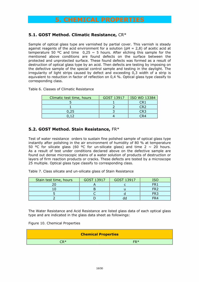
9.3. Pressed Blank Pressed blanks refer to glass articles already formed in lens blanks or prism blanks. Pressings are blanks formed by manually pressing softened glass.
Table 22. Dimensional pressings, min (1) and max (2) mm
Format Dia ± Dia CT ± CT R1 R2 V, cm3
1 10 ± 0,2 4 ± 0,3 PL PL 0,4 2 120 ± 1,0 20 ± 0,3 Rcx/Rcv Rcx/Rcv 288
Pressings are ordered by: glass code, glass type, pressed blank Dia x CT x ET x R1 (Rcx/Rcv) x R2 (Rcx/Rcv). On request tighter tolerance is acceptable with condition that customers furnish the final dimensions or drawings indicating the thickness of glass removal by grinding and polishing. Special orders for sliced discs, large molded blanks, window or mirror blanks and other miscellaneous shapes with various dimensions for special applications are acceptable on request.
9.4. Ophthalmologic Lens Blank The pressed ophthalmologic lens blanks 525-580 index glass for eyeglasses which specially designed for correctional glasses are delivering in the standard form. Table 23. Dimensional ophthalmologic lens blank
Format Designation Power
1 DIA 65 CT 3,2 ET 3,2 RCX 140 RCV 137 + 0,0
2 DIA 65 CT 3,5 ET 3,0 RCX 112 RCV 121 + 0,5
3 DIA 65 CT 4,0 ET 2,9 RCX 112 RCV 137 + 1,0
4 DIA 65 CT 4,2 ET 2,8 RCX 93 RCV 121 + 1,5
5 DIA 65 CT 4,8 ET 2,8 RCX 93 RCV 137 + 2,0
6 DIA 65 CT 4,9 ET 2,5 RCX 81 RCV 121 + 2,5
7 DIA 65 CT 2,7 ET 3,9 RCX 150 RCV 114 - 1,0
8 DIA 65 CT 2,5 ET 4,2 RCX 175 RCV 114 - 1,5
9 DIA 65 CT 2,5 ET 4,9 RCX 150 RCV 93 - 2,0
10 DIA 65 CT 2,5 ET 5,4 RCX 175 RCV 93 - 2,5
Ophthalmic lens blanks are ordered by: 525-580 BKC(U) lens blank Dia x CT x ET x Rcx x Rcv or drawing.

26/30
9.5. Droplet Glass droplet are supplied in a fire-polished form in a given weight specified by the customer and are available only for selected glass types.
We supply small diameter pre-formed glass droplet suitable for mould pressing into commercial lenses. Glass droplet is produced by direct molding of molten glasses with low softening properties. Shape of standard glass droplet is convex on both sides as shown on the figure below.
Figure 13. Glass droplets
Table 24. Dimensional droplet
Format Dia CT R1 R2 V, cm3
1 6,0 4,5 3,0 3,0 0,1 2 8,5 6,5 7,0 8,0 0,2 3 10,0 7,0 7,5 8,5 0,3 4 12,5 8,0 11,0 10,0 0,4 5 14,5 8,5 17,5 12,0 0,5
Droplet are ordered by: glass code, glass type, droplet Dia x CT x R1 x R2 or drawing.
9.6. Optical Element Optical elements or finished components polished, coated and assembled various lenses objectives and lenses for correctional eyeglasses and lenses such as camera lenses are available on request. Optical elements are ordered by: glass code, glass type, lens Dia x CT x ET and drawing.

27/30
10. PREFERRED PRODUCT LINE
10.1. Preferred Product Practice shows, that the principal optical glass types have high stable selling. Table 25. Preferred product line
POTAPENKO S.V., SPDFL Principal Properties
Glass Type Glass Code (d) Glass Code (e) nd Vd nF-nC ne Ve nF'-nC'
LK6 470 668 472 666 1,47046 66,83 0,007040 1,47214 66,64 0,007085
LK5 478 655 479 654 1,47817 65,59 0,007290 1,47990 65,44 0,007334
K8 516 640 518 638 1,51637 64,07 0,008060 1,51829 63,87 0,008115
FK11 519 691 521 689 1,51997 69,14 0,007520 1,52176 68,92 0,007570
BK10 568 560 571 557 1,56889 56,05 0,010150 1,57131 55,76 0,010245
FK14 579 650 582 648 1,57998 65,09 0,008910 1,58211 64,83 0,008979
OF6 601 510 604 508 1,60121 51,04 0,011780 1,60401 50,84 0,011880
F1 612 369 616 366 1,61294 36,95 0,016590 1,61688 36,69 0,016814
TK16 612 583 615 580 1,61269 58,35 0,010500 1,61519 58,08 0,010592
TK14 613 605 615 603 1,61309 60,58 0,010120 1,61551 60,33 0,010203
TF1 647 338 652 336 1,64766 33,87 0,019120 1,65219 33,62 0,019397
OF4 650 434 654 432 1,65063 43,46 0,014970 1,65419 43,25 0,015127
CTK3 659 573 662 570 1,65950 57,35 0,011500 1,66224 57,09 0,011600
OF5 662 417 666 415 1,66264 41,78 0,015860 1,66640 41,56 0,016033
CTK7 687 535 690 533 1,68701 53,59 0,012820 1,69006 53,31 0,012944
TF8 689 311 694 309 1,68949 31,13 0,022150 1,69473 30,90 0,022486
CTK12 692 550 695 547 1,69201 55,01 0,012580 1,69501 54,79 0,012684
CTK8 703 496 706 494 1,70312 49,69 0,014150 1,70650 49,41 0,014298
TF3 717 295 723 292 1,71741 29,51 0,024310 1,72317 29,29 0,024691
TF7 728 283 734 281 1,72822 28,34 0,025700 1,73429 28,12 0,026111
TF4 740 275 761 273 1,75523 27,53 0,027430 1,76171 27,32 0,027879
CTK9 742 502 746 500 1,74253 50,24 0,014780 1,74605 50,01 0,014918
CTK19 744 504 747 501 1,74413 50,42 0,014760 1,74765 50,19 0,014895
TF5 755 281 746 279 1,74002 28,16 0,026280 1,74623 27,94 0,026705
TF13 784 263 791 261 1,78466 26,33 0,029800 1,79169 26,13 0,030299
TBF9 808 427 812 425 1,80846 42,78 0,018900 1,81296 42,52 0,019118
TBF10 814 334 820 331 1,81481 33,42 0,024380 1,82057 33,17 0,024740

28/30
11. REFERENCE
11.1. Formulas Dispersion Formula nx
2 – 1 = A1 · λ2 + A2 · λ-2 + A3 · λ-4 + A4 · λ-6 + A5 · λ-8 (1) Partial Dispersion (nx - ny) (2) Main Partial Dispersion (nF - nC) and (nF' - nC’) (3) Abbe-number Vd = (nd - 1) / (nF - nC) (4) Ve = (ne - 1) / (nF' - nC’) (5) Relative Partial Dispersion Pd(x,y) = (nx - ny) / (nF - nC) (6) Pe(x,y) = (nx - ny) / (nF' - nC') (7) Deviation of Relative Partial Dispersions Pd(x,y) ~ ax,y + bx,y · Vd (8) Pe(x,y) ~ cx,y + dx,y · Ve (9) ∆Pd(x,y) = Pd(x,y) - ax,y - bx,y · Vd (10) ∆Pe(x,y) = Pe(x,y) - cx,y - dx,y · Ve (11) ∆Pe(i,F’) = Pe(i,F’) – 2,25801 + 0,0093272 · Ve (12) ∆Pe(g,F’) = Pe(g,F’) – 0,57035 + 0,0014832 · Ve (13) ∆Pe(F’,e) = Pe(F’,e) – 0,54290 + 0,0005702 · Ve (14) ∆Pe(F’,r) = Pe(F’,r) – 1,17926 + 0,0007208 · Ve (15) Internal Transmittance τx = τ0
d/d° (16)
Coefficient of Thermal Expansion CTE = L / ∆ L · ∆T (17)

29/30
Temperature Coefficient of Refractive Index NT abs = NT relative + nx · NT air (18) Specific Gravity SG ~ (nx
2 - 1) / (nx2 + 2) (19)
Grindability HG = (m / d) / (m0 / d0) · 100 (20) Knoop Hardness HK = 1,451 · F / L2 (21) Stress-Optical Coefficient Beta = ∆ nx / d / ∆ σ, (nm/cm · 10-5 Pa) (22) Farbcode (FC) FC = La λ0,8/ λ0,5 (23)
11.2. Abbreviates
nx - Refractive Index Vd - Abbe-number Ve - Alternative Abbe-number Pd(x,y) - Relative Partial Dispersion Pe(x,y) - Alternative Relative Partial Dispersion ∆Pd(x,y) - Deviation of Relative Partial Dispersions ∆Pe(x,y) - Alternative Deviation of Relative Partial Dispersions τx - Internal Transmittance CTE - Coefficient of Thermal Expansion NT abs - Absolute Temperature Coefficient of Refractive Index
NT relative - Relative Temperature Coefficient of Refractive Index NT air - Air Temperature Coefficient of Refractive Index SG - Specific Gravity HG - Grindability HK - Knoop Hardness Beta - Stress-Optical Coefficient SB - Stress Birefringence H - Homogeneity VS - Visible Striae VB - Visible Bubble P - Polished FC - Farbcode HT - Transmittance Tolerance CR* - Climatic Resistance. GOST Method FR* - Stain Resistance. GOST Method ST - Standard Quality SE - Increased Standard Quality PZ - Precision Quality SPZ - Super Precision Quality

30/30
11.3. Literature
1. GOST 3514. Optical glass. Specification. 2. GOST 13659. Optical glass. Physical and Chemical properties. 3. GOST 23136. Optical materials. Defects and classifications. 4. GOST 13917. Optical glass. Chemical test methods. 5. GOST 13240. Optical glass blanks. Technical conditions. 6. DIN 58925. Optical glass. Principal concepts. 7. ISO 10110. Issuing of drawings for optical elements. 8. ISO 12844. Optical raw glass. Test methods. 9. OPTOPROM. Optical materials. Catalogue. Moscow 2003. 10. SCHOTT GLASS. Catalogue. Version 1.1 E Status 02/2001. 11. HOYA GLASS. Catalogue. USA Divisions. Version 2002. 12. OHARA GLASS. Catalogue. FRG Divisions. Version 2002.
Note 6:
♦ Potapenko is the sole owner of the information collected into this technical catalogue and will
not make express modifications this information to others in ways different from what is disclosed as this catalogue text. The above technical catalogue text is version of the our company. In the event of ambiguity or difference arising between the version of the catalogue text and his modified information, modern version of the catalogue text shall prevail.
♦ This catalogue text may contain inadvertent inaccuracies or typographical errors. These will be
corrected at Potapenko's discretion, as they are found. The information on this catalogue text is updated regularly, but inaccuracies may occur where changes occur between updates.
♦ Potapenko has used and will use reasonable efforts to include accurate and up-to-date
information on his catalogue. However, Potapenko makes no warranties or representations, express or implied, as to the timeliness, accuracy or completeness of the information contained or referenced in this version of the catalogue text.
♦ Please contact us for reception of modern version of the catalogue text and other exacter
technical data.
POTAPENKO S.V., SPDFL UKRAINIAN DISTRIBUTOR OF OPTICAL GLASS
Version 01-2004 www.opticalglass.com.ua