Embed Size (px)
Citation preview

Optics Communications 344 (2015) 139–146
Contents lists available at ScienceDirect
Optics Communications
http://d0030-40
n Corrgineerin
E-m
journal homepage: www.elsevier.com/locate/optcom
Optical frequency comb generation based on chirpingof Mach–Zehnder Modulators
Jassim K. Hmood a,b, Siamak D. Emami a, Kamarul A. Noordin a, Harith Ahmad c,Sulaiman W. Harun a,c,n, Hossam M.H. Shalaby d
a Department of Electrical Engineering, Faculty of Engineering, University of Malaya, 50603 Kuala Lumpur, Malaysiab Laser and Optoelectronic Department, University of Technology, Baghdad 10066, Iraqc Photonics Research Center, University of Malaya, Kuala Lumpur 50603, Malaysiad Department of Electronics and Communications Engineering, Egypt-Japan University of Science and Technology, Alexandria 21934, Egypt
a r t i c l e i n f o
Article history:Received 14 November 2014Received in revised form15 January 2015Accepted 19 January 2015Available online 21 January 2015
Keywords:Chirp factorOptical frequency combOptical fiber communicationOptical modulator
x.doi.org/10.1016/j.optcom.2015.01.05418/& 2015 Elsevier B.V. All rights reserved.
esponding author at: Department of Electricag, University of Malaya, 50603 Kuala Lumpurail address: [email protected] (S.W. Harun
a b s t r a c t
A new approach for the generation of an optical frequency comb, based on chirping of modulators, isproposed and numerically demonstrated. The setup includes two cascaded Mach–Zehnder Modulators(MZMs), a sinusoidal wave oscillator, and an electrical time delay. The first MZM is driven directly by asinusoidal wave, while the second MZM is driven by a delayed replica of the sinusoidal wave. A math-ematical model of the proposed system is formulated and modeled using the Matlab software. It isshown that the number of the frequency lines is directly proportional to the chirp factor. In order toachieve the highest number of frequency comb lines with the best flatness, the time delay between thedriving voltages of the two MZMs is optimized. Our results reveal that at least 51 frequency lines can beobserved at the output spectrum. In addition, 27 of these lines have power fluctuations of less than 1 dB.The performance of the proposed system is also simulated using a split-step numerical analysis. Anoptical frequency comb, with tunable frequency spacing ranging from 5 to 40 GHz, is successfully gen-erated.
& 2015 Elsevier B.V. All rights reserved.
1. Introduction
Nowadays, optical frequency comb generator (OFCG) is widelyused as multi-wavelength source for optical communication sys-tems such as dense wavelength-division multiplexing (DWDM),optical time-division multiplexing, and optical orthogonal fre-quency-division multiplexing systems [1–6]. The generated combis required to provide a stable frequency with a fixed phase andspacing for these applications. In addition, the flatness of spectralcomb lines and low implementation costs are also vital require-ments. Till today, many techniques have been proposed and de-veloped to realize optical frequency combs (OFCs) such as theemployment of a mode locked laser (MLL) [7,8]. The instability ofcarrier frequency due to the environment's dependency of lasercavity is the main disadvantage of MLL method [3]. Anothertechnique is based on nonlinear effects in a highly nonlinearmedium [9]. However, this technique requires a high power am-plifier and an optical filter to shape the spectrum. Optical
l Engineering, Faculty of En-, Malaysia.).
modulation technique can also be used to realize OFC wherebymultiple optical carriers with precise channel spacing can be ob-tained from one seed light source [10–14]. Low cost, low com-plexity, small size, less noise [14], and high stability are some ofthe main advantages of this technique.
Many schemes have been used for generating OFCs such as byimplementing optical modulation technique. This modulation isnormally based on two approaches; amplitude-phase hybridmodulation and intensity modulation. In amplitude-phase hybridmodulation scheme, the number of generated comb lines is di-rectly proportion to phase modulation (i.e. to tune the number ofcomb lines, the amplitude of electrical-oscillator signal is con-trolled) [10–12]. The limitations of this technique are mainly dueto the limited number of generated comb lines and the use of highpower of external RF to drive the modulators. Wu et. al. success-fully demonstrated a 10 GHz comb with 38 lines within a spectralpower variation of 1 dB by cascading intensity and phase mod-ulations [11]. The problem of high power of external RF can besolved by employing optical intensity modulators with a lowdriving voltage. Shang et. al. used two cascaded intensity mod-ulators to generate a 25 comb lines at low driving voltage [15].
In the optical intensity modulator, the change of phase of theoutput light with time causes a chirping in the optical signal. The

J.K. Hmood et al. / Optics Communications 344 (2015) 139–146140
chirping allows the frequency of the optical signal to be increased(positive chirp) or decreased (negative chirp) during varying thedriving signal. The chirping behavior of MZMs is often character-ized by chirp factor [16]. The chirp factor is the intrinsic parameterto an optical modulator and depends on the device structures ofoptical modulators, such as the relation between the optical wa-veguides and the electrodes[17]. For producing high chirp factor,asymmetric MZM can be employed [18]. Most MZMs are fabricatedwith symmetric structure. They are manufactured for using asmodulators with approximately zero-chirp factor. However, thereare many techniques to control the chirping of symmetric MZMs.Changing the voltage biasing is easiest techniques to adjust thechirping of modulators where the chirp factor has been changedfrom �4 to 5 [19]. The chirp factor has also been controlled byintroducing phase reversal electrode section in tandem with in-verted ferroelectric domain section [20].
It is worth mentioning, in previous works, the amplitude andphase of driving voltages are tuned to generate a number of fre-quency lines while modulators have been assumed chirp-freemodulators [11,21]. In this paper, a new technique to generate aflat and stable optical frequency comb is proposed based on em-ploying MZMs with high chirp factors to reshape the modulatedoptical signal. The performance of the proposed technique is in-vestigated for two different setups. The first setup employs only asingle MZM, where electrical sinusoidal waveform is used tomodulate the optical signal. The second setup uses two cascadedMZMs and a time delayer. This setup resembles the one proposedby Healy et. al. [22] where a dual-drive MZM is used. However theideas behind the OFCG operation are different. In the work ofHealy et. al., by adjusting the relative optical and RF phases ofupper and lower interferometer arms, a non-flat but com-plementary optical spectra was obtained from phase modulation.However, a relatively flat optical frequency comb can be achievedby tuning and recombining the phases of the two arms. For theproposed setup, the first MZM is driven directly by a sinusoidalwave, while the second MZM is driven by a delayed replica of thesinusoidal wave. The time delay between the sinusoidal waves isused to reduce the power fluctuation in the generated opticalcomb spectrum. Specifically, we develop a mathematical model forboth setups to prove the influence of the chirp factor on thenumber and flatness of generated frequency lines. The effect ofMZM chirping on performance of both OFCGs is investigated usingthe mathematical analysis. Our mathematical model is validatedby comparing the analytical results with simulation results ob-tained using the VPItransmissionMaker software.
The rest of the letter is organized as follows. In Section 2, theconfigurations of the proposed OFCG setups are introduced alongwith their mathematical models. Simulation results that providethe power spectra of the proposed OFCGs are presented in Section3. Finally, the conclusion is given in Section 4.
2. System description and mathematical analysis
In this section, we introduce the configurations of the proposedOFCG setups. We also provide a simple mathematical model thatbest describes the proposed systems.
2.1. Single MZM configuration
We start our system description by providing an OFCG setupthat is based on a single MZM.
Fig. 1 shows the configuration of this setup, which consists of adual-electrode MZM, a CW laser source, and a periodic sinusoidalwave generator of period T. The schematic of a typical split (upperand lower) and dual electrode (separate DC and RF) configured
Mach–Zehnder external modulator is shown in Fig. 1. This elec-trode configuration allows for separate control of both DC and RFmodulating signals, as well as separate electro-optic control ofboth upper and lower arms of the MZM. The optical signals thatpass through the arms of the MZM are chirped and their phasesare simultaneously changed. Subsequently, the optical signals,which are obtained from two arms, are recombined to generate arelatively flat comb lines. In this setup, the optical CW laser ismodulated by an electrical sinusoidal wave which is shifted by aDC voltage. Let the input optical field to the MZM be expressed as
E t P j f( ) exp ( 2 ) (1)i o oπ=
where Po and fo are the power and frequency of the input opticalcarrier, respectively. The corresponding output optical field can bewritten as [16,23]
⎪ ⎪
⎧⎨⎩
⎛⎝⎜
⎞⎠⎟
⎛⎝⎜
⎞⎠⎟
⎫⎬⎭E t
E tj
V tV
jV t
V( )
( )2
exp(1 ) ( )
exp(1 ) ( )
(2)o
i 1 2α π α π=
++
−π π
where V1(t) and V2(t) are the electrical driving signals supplied toboth upper and lower MZM electrodes, respectively, α is a chirpfactor and Vπ is the voltage required to produce a 180° phase shift.In order to operate at a push–pull mode, the driven voltages ofMZM are set V2(t)¼�V1(t). We assume that
{ }V t V t V( )12
sin ( ) (3)rf r dc1 ω= +
where Vdc is a DC voltage, Vrf is the amplitude of the sinusoidalwave, ωr¼2πfr, and fr¼1/T is the frequency of the sinusoidal wave.Substituting in (2), we get
⎧⎨⎪⎩⎪
⎛
⎝⎜⎜
⎞
⎠⎟⎟
⎛
⎝⎜⎜
⎞
⎠⎟⎟
⎫⎬⎪⎭⎪
( )
( )
E tE t
jV t V
V
jV t V
V
( )( )2
exp(1 ) sin ( )
2
exp(1 ) sin ( )
2 (4)
oi rf r dc
rf r dc
α π ω
α π ω
=+ +
+ −− +
π
π
Then, the equation can be simplified as
E t
E tjA t jA jA t
jA
( )
( )2
{ exp [ sin ( )] exp ( ) exp [ sin ( )]
exp ( )} (5)
o
ir r2 1 4
3
ω ω= + −
−
where;
AV
V
AV
V
AV
V
AV
V
(1 )2
,
(1 )2
,
(1 )2
, and
(1 )2
.
dc
rf
dc
rf
1
2
3
4
π α
π α
π α
π α
= +
= +
= −
= −
π
π
π
π
For achieving modulation in intensity, the MZM should beoperated at the quadrature point, where a DC bias is Vπ/2 and apeak-to-peak modulation is Vπ. Then Vrf, which represents thepeak of RF signal should be equal to Vπ/2. This mode of operationallows the output optical signal to increase and decrease aroundthe operating point of MZM without distortion as the RF signalswings through a complete cycle. Assuming that V VV /2rf dc= = π , wehave A A1 2= and A A A/23 4 1π= = − . SubstitutingA2, A3 and A4 interms of A1in (5), we get
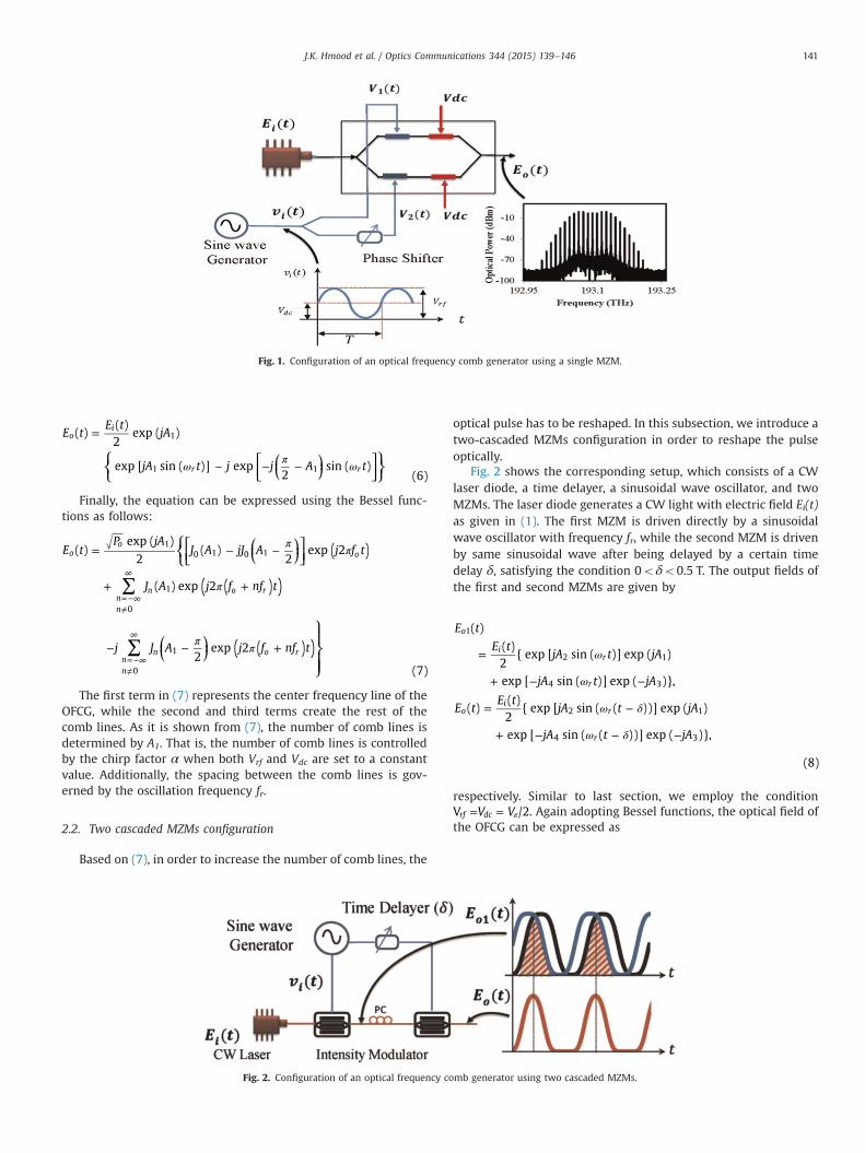
Fig. 1. Configuration of an optical frequency comb generator using a single MZM.
J.K. Hmood et al. / Optics Communications 344 (2015) 139–146 141
⎜ ⎟⎧⎨⎩
⎡⎣⎢
⎛⎝
⎞⎠
⎤⎦⎥
⎫⎬⎭
E tE t
jA
jA t j j A t
( )( )2
exp ( )
exp [ sin ( )] exp2
sin ( )(6)
oi
r r
1
1 1ω π ω
=
− − −
Finally, the equation can be expressed using the Bessel func-tions as follows:
⎜ ⎟
⎜ ⎟
⎧⎨⎩⎡⎣⎢
⎛⎝
⎞⎠
⎤⎦⎥
⎛⎝
⎞⎠
⎫⎬⎪
⎭⎪⎪
( )
( )
( )
( )
( )
E tP jA
J A jJ A j f t
J A j f nf t
j J A j f nf t
( )exp ( )
2( )
2exp 2
( ) exp 2
2exp 2
(7)
oo
o
nn
n o r
nn
n o r
10 1 0 1
0
1
0
1
∑
∑
π π
π
π π
= − −
+ +
− − +
=−∞≠
∞
=−∞≠
∞
The first term in (7) represents the center frequency line of theOFCG, while the second and third terms create the rest of thecomb lines. As it is shown from (7), the number of comb lines isdetermined by A1. That is, the number of comb lines is controlledby the chirp factor α when both Vrf and Vdc are set to a constantvalue. Additionally, the spacing between the comb lines is gov-erned by the oscillation frequency fr.
2.2. Two cascaded MZMs configuration
Based on (7), in order to increase the number of comb lines, the
Fig. 2. Configuration of an optical frequency co
optical pulse has to be reshaped. In this subsection, we introduce atwo-cascaded MZMs configuration in order to reshape the pulseoptically.
Fig. 2 shows the corresponding setup, which consists of a CWlaser diode, a time delayer, a sinusoidal wave oscillator, and twoMZMs. The laser diode generates a CW light with electric field Ei(t)as given in (1). The first MZM is driven directly by a sinusoidalwave oscillator with frequency fr, while the second MZM is drivenby same sinusoidal wave after being delayed by a certain timedelay δ, satisfying the condition 0oδo0.5 T. The output fields ofthe first and second MZMs are given by
E t
E tjA t jA
jA t jA
E tE t
jA t jA
jA t jA
( )
( )2
{ exp [ sin ( )] exp ( )
exp [ sin ( )] exp ( )},
( )( )2
{ exp [ sin ( ( ))] exp ( )
exp [ sin ( ( ))] exp ( )},
(8)
o
ir
r
oi
r
r
1
2 1
4 3
2 1
4 3
ω
ω
ω δ
ω δ
=
+ − −
= −
+ − − −
respectively. Similar to last section, we employ the conditionV VV /2rf dc= = π . Again adopting Bessel functions, the optical field of
the OFCG can be expressed as
mb generator using two cascaded MZMs.

J.K. Hmood et al. / Optics Communications 344 (2015) 139–146142
⎜ ⎟
⎜ ⎟
⎡⎣⎢⎢
⎛⎝
⎞⎠
⎤⎦⎥⎥
⎡⎣⎢⎢
⎛⎝
⎞⎠
⎤⎦⎥⎥
E tE t j A
J A jn t
j J A jn t
J A jn t
j J A jn t
( )( ) exp ( 2 )
4
( ) exp ( )
2exp ( )
( ) exp ( ( ))
2exp ( ( ))
(9)
oi
nn r
nn r
nn r
nn r
1
1
1
1
1
∑
∑
∑
∑
ω
π ω
ω δ
π ω δ
=
− −
× −
− − −
=−∞
∞
=−∞
∞
=−∞
∞
=−∞
∞
3. Results and discussion
In this section, we present a simulation result of our proposedsystems, which was obtained using the VPItransmissionMakercommercial software. The simulated results are also comparedwith theoretical results obtained from the mathematical analysisdeveloped in the last section for comparison purpose. Moreover,our proposed systems are tested by changing the chirp factor from3 to 9. Because the highest value of chirp factor has been experi-mentally measured at α¼5 [19], most results of our paper areobtained at α¼5.
3.1. Simulation results of single MZM configuration
The single-MZM comb generator described in Fig. 1 has beensimulated and the resulting optical spectra are depicted inFigs. 3 and 4. In our setup, a 10 dBm CW optical carrier is gener-ated by a laser diode with a frequency of 193.1 THz and a linewidth
Fig. 3. Optical spectra of a single-MZM comb generator with a constant chirp factor α¼5(d) fr¼40 GHz.
of 100 kHz. The driven voltages of MZM are adjusted toV VV /2rf dc= = π .
In Fig. 3, we plot the optical spectra of a single-MZM combgenerator with a constant chirp factor α¼5 for different oscillationfrequencies varying from 5 GHz to 40 GHz. Fig. 3(a) shows theoutput spectrum with oscillation frequency of 5 GHz, where it canbe seen that 23 comb lines can be generated. The frequency spa-cing between the lines is 5 GHz, while the bandwidth is 115 GHz.As expected, as an oscillation frequency is increased to 10 GHz, thenumber of comb lines remains constant, but the frequency spacingbetween the lines is increased to 10 GHz and the bandwidth isdoubled as shown in Fig. 3(b). Similarly, by increasing the oscil-lation frequency even further, the number of comb lines remainsconstant, but both the frequency spacing and bandwidth are in-creased accordingly, as depicted in Fig. 3(c) and (d). Fig. 4 showsthe relation between the number of frequency lines and the chirpfactor, where the optical spectra for chirp factors of 3, 5, 7, and9 are depicted in the figure. The oscillation frequency is set con-stant at fr¼10 GHz. It can be seen from the figure that comb linescounts of 19, 23, 29, and 33 are achieved when the chirp factor isset to 3, 5, 7, and 9, respectively. The simulation results show thatthe number of frequency lines in the optical comb generator isbroadly tunable by changing the chirp factor, which agrees withthe mathematical analysis of the output optical field Eo(t) obtainedin (7).
3.2. Simulation results of two-cascaded MZMs configuration
The cascaded-MZMs OFCG of Fig. 2 is simulated with input CWlight of frequency fo¼193.1 THz and optical power of 10 dBm. Theoscillation frequency is set fixed at fr¼10 GHz, while the ampli-tude and biasing of the input sinusoidal wave are selected so that
⎡⎣ ⎤⎦v t V f t V( ) 0.5 sin (2 )i rπ= +π π . Furthermore, the time delay δ is
for different oscillation frequencies: (a) fr¼5 GHz, (b) fr¼10 GHz, (c) fr¼20 GHz and

Fig. 4. Optical spectra of a single-MZM comb generator with a constant fr¼10 GHz for different chirp factors: (a) α¼3, (b) α¼5, (c) α¼7 and (d) α¼9.
J.K. Hmood et al. / Optics Communications 344 (2015) 139–146 143
adjusted to zero and the chirp factors for both MZMs are assumedto be identical and take values in the set {3, 5, 7, 9}α ∈ . The opticalspectra obtained by the simulation are shown in Fig. 5. It can be
Fig. 5. Optical spectra of a cascaded-MZMs comb generator with fr¼10 GHz an
seen from Fig. 5(a) that using a chirp factor α¼3, the proposedOFCG setup generates an optical power spectrum with 23 comblines. Increasing α to 5, 7, and 9, yields 35, 43, and 51 comb lines in
d δ¼0 for different chirp factors: (a) α¼3, (b) α¼5, (c) α¼7 and (d) α¼9.

Fig. 6. Number of frequency lines versus chirp factor of second MZM at variousvalues for chirp factors of first MZM.
Fig. 7. Optical spectra of a cascaded-MZMs comb generator at a constant fr¼10 GHz and α¼5 for different delay times: (a) δ¼0, (b) δ¼0.1 T, (c) δ¼0.15 T and (d) δ¼0.2 T.
J.K. Hmood et al. / Optics Communications 344 (2015) 139–146144
the optical spectra, respectively. This shows that, increasing thechirp factor would increase both the number of comb lines andfluctuation. This phenomenon results from the multiplication of alot of sinusoidal waveforms. In agreement with (9), a higher valueof chirp factor leads to more harmonic frequencies and wideroptical spectra.
Fig. 6 depicts the number of frequency lines with fluctuationpower of less than 1 dB as a function of chirp factor α. In order tohave insight of presented system setup, the chirp factor of secondMZM in the cascaded setup is varied from 1 to 11 while the firstMZM is fixed at 3, 5, 7, and 9. The highest frequency comb lines areachieved at highest value of chirp factors. The corresponding va-lues from analytical results are also indicated in the same figure,which shows good agreement with simulation results.
3.2.1. Optimizing the flatnessIn order to improve the flatness of optical spectrum, the input
wave amplitude, biasing and time delay should be optimized. Forexample, let the amplitude and biasing of the input wave be set sothat vi(t)¼0.5Vπ sin(2πfrt)þ0.4Vπ and the time delay is variedfrom 0 to 0.2 T, while the chirp factor for both MZMs is fixed at 5.The DC value of 0.4Vπ achieves the lowest power fluctuation and itis obtained by varying Vdc using the VPI software. The corre-sponding optical spectra are shown in Fig. 7. By adjusting δ¼0, the0.9 dB power fluctuation can be obtained from Fig. 7(a). Increasingδ to 0.1 T, 0.15 T, and 0.2 T, produces 0.55, 0.45, and 0.7 dB powerfluctuation in the optical spectra, respectively. That is, lower powerfluctuation is observed in the optical spectrum at time delay of 15%of wave period where the two MZMs are operating in optimumcondition, Fig. 7(c).
In order to explore more the effect of delay time on flatness ofoptical combs, the optical power fluctuation versus delay time is
plotted in Fig. 8. In agreement with Fig. 7, the minimum fluctua-tion is achieved at δ¼0.15 T for all chirp factor values of 5, 7, and 9.In addition, the effect of delay timer on number of frequency linesis also demonstrated in Fig. 8. As it can be seen, the number offrequency lines is related inversely to delay time. For the sake ofconvenience, in Fig. 9 we plot the optical power fluctuation andnumber of frequency lines versus delay time for the case when Vdc
¼0.5Vπ. It can be noticed that at δ¼0, although the number ofcomb lines are higher than that of the previous case of Vdc¼0.4Vπ,the corresponding power fluctuations are also higher. It is alsoseen that the points of minimum power fluctuations occur at afixed point of 0.2 T. From the last two figures, we have the fol-lowing observations at the points of minimum power fluctuations.At α¼5, the number of comb lines is 9 for both cases of Vdc¼0.4Vπand Vdc¼0.5Vπ . However, the corresponding power fluctuations

Fig. 8. Power fluctuation and number of frequency lines versus delay time δ at Vdc
¼0.4Vπ for various chirp factors.
Fig. 9. Power fluctuation and number of frequency lines versus delay time δ at Vdc
¼0.5Vπ for various chirp factors.
Fig. 10. The optimal delay time and power fluctuation as a function of Vdc at chirpfactor of α¼5.
J.K. Hmood et al. / Optics Communications 344 (2015) 139–146 145
are 0.45 dB and 0.55 dB, respectively. Also, for α¼7, the number ofcomb lines is 15 for both cases of Vdc¼0.4Vπ and Vdc¼0.5Vπ, andthe corresponding fluctuations are 0.5 dB and 0.65 dB, respec-tively. Moreover, for α¼9, the number of comb lines is 21 withpower fluctuations of 0.65 dB for the case of Vdc¼0.4Vπ, while thenumber of comb lines is 19 with power fluctuations of 0.75 dB forthe other case of Vdc¼0.5Vπ . Furthermore, it is seen that the effect
of time delay on the power fluctuation is higher for suboptimumscenarios. For example, in Fig. 9 with α¼5, the fluctuation ischanged from 1.8 to 0.55 dB when δ is varied from 0 to 0.2 T,while, in Fig. 8 with same chirp factor, the fluctuation is changedfrom 0.9 to 0.45 dB only when δ is varied from 0 to 0.15 T. Fig. 10shows both the optimal delay time and fluctuation as a function ofVdc at chirp factor of α¼5. The optimal delay time increases lin-early with the increment of the biasing voltage. Conversely, thefluctuation grows in magnitude when the biasing voltage is loweror greater than 0.4Vπ.
4. Conclusion
A new approach for generating an optical frequency combbased on chirping of two cascaded MZMs has been proposed. TheMZMs are driven by a sinusoidal wave oscillator and its delayedreplica in order to produce periodic optical pulses. A broadbandoptical spectrum with a large number of frequency lines and goodflatness has been achieved in the proposed setup. It has been seenthat the flatness of optical spectra is improved by adjusting thedelay time between the driven voltages of two MZM. The band-width of the optical comb signal is determined by the frequency ofthe sinusoidal wave, the chirp factor, and the time delay. Our re-sults reveal that more than 35 frequency lines can be obtained at achirp factor of 5. Furthermore, 13 comb lines can be achieved withpower variation of less than 1 dB. The results showed the con-siderable approach for generation OFCGs.
References
[1] Z. Jiang, D.E. Leaird, C.-B. Huang, H. Miao, M. Kourogi, K. Imai, A.M. Weiner,Spectral line-by-line pulse shaping on an optical frequency comb generator,IEEE J. Quantum Electron. 43 (2007) 1163–1174.
[2] H.-J. Song, N. Shimizu, T. Furuta, K. Suizu, H. Ito, T. Nagatsuma, Broadband-frequency-tunable sub-terahertz wave generation using an optical comb,AWGs, optical switches, and a uni-traveling carrier photodiode for spectro-scopic applications, J. Lightw. Technol. 26 (2008) 2521–2530.
[3] I. Morohashi, T. Sakamoto, H. Sotobayashi, T. Kawanishi, I. Hosako, Broadbandoptical comb generation using Mach–Zehnder-modulator-based flat combgenerator with feedback loop, in: Proceedings of the 36th European Con-ference and Exhibition on Optical Communication (ECOC), IEEE, 2010, pp. 1–3.
[4] S.E. Mirnia, A. Zarei, S.D. Emami, S.W. Harun, H. Arof, H. Ahmad, H.M. Shalaby,Proposal and performance evaluation of an efficient RZ-DQPSK modulationscheme in all-optical OFDM transmission systems, J. Opt. Commun. Netw. 5(2013) 932–944.
[5] B.J. Chun, S. Hyun, S. Kim, S.-W. Kim, Y.-J. Kim, Frequency-comb-referencedmulti-channel fiber laser for DWDM communication, Opt. Express 21 (2013)29179–29185.
[6] C. Chen, C. Zhang, W. Zhang, W. Jin, K. Qiu, Scalable and reconfigurable gen-eration of flat optical comb for WDM-based next-generation broadband op-tical access networks, Opt. Commun. 321 (2014) 16–22.
[7] E. Benkler, F. Rohde, H.R. Telle, Endless frequency shifting of optical frequencycomb lines, Opt. Express. 21 (2013) 5793–5802.
[8] Y.-J. Kim, J. Jin, Y. Kim, S. Hyun, S.-W. Kim, A wide-range optical frequencygenerator based on the frequency comb of a femtosecond laser, Opt. Express.16 (2008) 258–264.
[9] X. Yang, D.J. Richardson, P. Petropoulos, Broadband, flat frequency combgenerated using pulse shaping-assisted nonlinear spectral broadening, IEEEPhoton. Technol. Lett. 25 (2013) 543–545.
[10] V. Torres‐Company, A.M. Weiner, Optical frequency comb technology for ul-tra‐broadband radio‐frequency photonics, Laser Photon. Rev. 8 (2014)368–393.
[11] R. Wu, V. Supradeepa, C.M. Long, D.E. Leaird, A.M. Weiner, Generation of veryflat optical frequency combs from continuous-wave lasers using cascaded in-tensity and phase modulators driven by tailored radio frequency waveforms,Opt. Lett. 35 (2010) 3234–3236.
[12] C. Chen, C. Zhang, D. Liu, K. Qiu, S. Liu, Tunable optical frequency comb en-abled scalable and cost-effective multiuser orthogonal frequency-divisionmultiple access passive optical network with source-free optical networkunits, Opt. Lett. 37 (2012) 3954–3956.
[13] L. Shang, A. Wen, G. Lin, Y. Gao, A flat and broadband optical frequency combwith tunable bandwidth and frequency spacing, Opt. Commun. 331 (2014)262–266.
[14] M. Wang, X. Zhang, Tunable Optical Frequency Comb Generation Based on an

J.K. Hmood et al. / Optics Communications 344 (2015) 139–146146
Optoelectronic Oscillator, IEEE Photon. Technol. Lett. 25 (2013) 2035–2038.[15] L. Shang, A. Wen, G. Lin, Optical frequency comb generation using two cas-
caded intensity modulators, J. Opt. 16 (2014) 035401.[16] F. Koyama, K. Iga, Frequency chirping in external modulators, J. Lightw.
Technol. 6 (1988) 87–93.[17] S. Oikawa, T. Kawanishi, M. Izutsu, Measurement of chirp parameters and
halfwave voltages of Mach–Zehnder-type optical modulators by using a smallsignal operation, IEEE Photon. Technol. Lett. 15 (2003) 682–684.
[18] J. Nayyer, H. Nagata, S. Shimotsu, S. Oikawa, M. Yamada, Modulation char-acteristics of high-speed optical modulators with properly split asymmetryinto their Mach-Zehnder arms, Electron. Lett. 31 (1995) 387–388.
[19] M. Schiess, H. Carlden, Evaluation of the chirp parameter of a Mach–Zehnderintensity modulator, Electron. Lett. 30 (1994) 1524–1525.
[20] N. Courjal, H. Porte, A. Martinez, J.-P. Goedgebuer, LiNbO3 Mach–Zehndermodulator with chirp adjusted by ferroelectric domain inversion, IEEE Photon.Technol. Lett. 14 (2002) 1509–1511.
[21] T. Sakamoto, T. Kawanishi, M. Izutsu, Asymptotic formalism for ultraflat opticalfrequency comb generation using a Mach–Zehnder modulator, Opt. Lett. 32(2007) 1515–1517.
[22] T. Healy, F.C. Garcia Gunning, A.D. Ellis, J.D. Bull, Multi-wavelength sourceusing low drive-voltage amplitude modulators for optical communications,Opt. Express. 15 (2007) 2981–2986.
[23] K.-P. Ho, J.M. Kahn, Spectrum of externally modulated optical signals, J. Lightw.Technol. 22 (2004) 658.