Embed Size (px)
Citation preview

OPERATOR’SMANUAL
18.5, 21, 26HP Zero-Turn RidersMfg. No. Description7800611 Simplicity Axion Model ZT18533, 18.5HP w/ 33” Mower7800616 Simplicity Axion Model CZT18533, 18.5HP w/ 33” Mower (California Model)7800620 Snapper 150Z Model SC18533, 18.5HP w/ 33” Mower7800625 Snapper 150Z Model CSC18533, 18.5HP w/ 33” Mower (California Model)7800612 Simplicity Axion Model ZT2142, 21HP w/ 42” Mower7800617 Simplicity Axion Model CZT2142, 21HP w/ 42” Mower (California Model)7800615 Simplicity Axion Model ZT2142, 21HP w/ 42” Mower (Australia Model)7800621 Snapper 150Z Model SC2142, 21HP w/ 42” Mower7800626 Snapper 150Z Model CSC2142, 21HP w/ 42” Mower (California Model)7800624 Snapper 150Z Model SC2142, 21HP w/ 42” Mower (Australia Model)7800630 Snapper 150Z Model SC26520, 26HP w/ 52” Mower
Axion / 150Z Series
Manual No. 7103857Revision ‘-’, 10/27/2009
Not for
Reprod
uctio
n

Not for
Reprod
uctio
n

3
TABLE OF CONTENTS
Safety RulesGeneral Operation...................................................4Transportation & Storage ........................................4Slope Operation ......................................................5Towed Equipment....................................................5Children...................................................................5Emissions................................................................5Ignition System .......................................................5Slope Sighting Guide ..............................................6Service & Maintenance ...........................................7Safety & Operation Decals......................................8
Identification Numbers................................................9Operation
Control Functions..................................................10General Operating Safety .....................................11Checks before Starting..........................................12Fuel Recommendations ........................................12Emergency Stopping.............................................13Stopping the Rider and Engine .............................13Starting the Engine ...............................................13Mowing..................................................................13Pushing the Rider by Hand ...................................13Driving Practice.....................................................14Mower Deck Removal & Installation......................16
MaintenanceMaintenance Schedule .........................................18Rider MaintenanceAccessing the Engine Compartment.....................19Clean Debris from Rider and Engine ....................19Clean Debris from Engine Cooling Areas .............19Check Tire Pressure..............................................19Lubrication ............................................................20Clean Deck & Check/Replace Mower Blades .......21Clean the Battery & Cables...................................24Check Rider Safety System ..................................24Check/Adjust PTO Clutch......................................25Engine MaintenanceCheck Engine Oil Level .........................................26Change Engine Oil ................................................26Change Engine Oil & Filter ...................................26Service Air Filter & Pre-Cleaner............................27Replace Spark Plug ..............................................29
Service & AdjustmentsGround Speed Control Lever Adjustment .............30Speed Balancing Adjustment ................................30Cutting Height Adjustment ....................................30PTO Clutch Adjustment.........................................30Brake Adjustment..................................................31Battery Charging ...................................................31Engine Adjustments ..............................................31Mower Deck Leveling Adjustments .......................32Mower Belt Replacement ......................................36Storage..................................................................37
TroubleshootingTroubleshooting the Rider - Chart .........................38Troubleshooting the Mower - Chart .......................39
Specifications ............................................................40Service Items .............................................................41Lawn Care ..............................................................LC-1
NOTE: In this manual, “left” and “right” are referred to as seen from the operating position.
Not for
Reprod
uctio
n

4
SAFETY RULES
GENERAL OPERATION1. Read, understand, and follow all instructions in the
manual and on the unit before starting.2. Do not put hands or feet near rotating parts or under
the machine. Keep clear of the discharge opening atall times.
3. Only allow responsible adults, who are familiar withthe instructions, to operate the unit (local regulationscan restrict operator age).
4. Clear the area of objects such as rocks, toys, wire,etc., which could be picked up and thrown by theblade(s).
5. Be sure the area is clear of other people beforemowing. Stop the unit if anyone enters the area.
6. Never carry passengers.7. Do not mow in reverse unless absolutely necessary.
Always look down and behind before and whiletravelling in reverse.
8. Never direct discharge material toward anyone. Avoiddischarging material against a wall or obstruction.Material may ricochet back toward the operator. Stopthe blade(s) when crossing gravel surfaces.
9. Do not operate the machine without the entire grasscatcher, discharge guard (deflector), or other safetydevices in place and operational.
10. Slow down before turning.11. Never leave a running unit unattended. Always
disengage the blades (PTO), set parking brake, stopengine, and remove keys before dismounting.
12. Disengage blades (PTO) when not mowing. Shut offengine and wait for all parts to come to a completestop before cleaning the machine, removing the grasscatcher, or unclogging the discharge guard.
13. Operate the machine only in daylight or good artificiallight.
14. Do not operate the unit while under the influence ofalcohol or drugs.
15 Watch for traffic when operating near or crossingroadways.
16. Use extra care when loading or unloading the unitinto a trailer or truck.
17. Always wear eye protection when operating this unit.18. Data indicates that operators, age 60 years and
above, are involved in a large percentage of powerequipment-related injuries. These operators shouldevaluate their ability to operate the equipment safelyenough to protect themselves and others from injury.
19. Follow the manufacturer’s recommendations for wheelweights or counterweights.
20. Keep in mind the operator is responsible for accidentsoccurring to other people or property.
21. All drivers should seek and obtain professional andpractical instruction.
22. Always wear substantial footwear and trousers.Never operate when barefoot or wearing sandals.
23. Before using, always visually check that the bladesand blade hardware are present, intact, and secure.Replace worn or damaged parts.
24. Disengage attachments before: refueling, removingan attachment, making adjustments (unless theadjustment can be made from the operator’sposition).
25. When the machine is parked, stored, or leftunattended, lower the cutting means unless a positivemechanical lock is used.
26. Before leaving the operator’s position for any reason,engage the parking brake, disengage the blades(PTO), stop the engine, and remove the key.
27. To reduce fire hazard, keep the unit free of grass,leaves, & excess oil. Do not stop or park over dryleaves, grass, or combustible materials.
28. It is a violation of California Public Resource CodeSection 4442 to use or operate the engine on or nearany forest-covered, brush-covered, or grass-coveredland unless the exhaust system is equipped with aspark arrester meeting any applicable local or statelaws. Other states or federal areas may have similarlaws.
29. OSHA regulations may require the use of hearingprotection when exposed to sound levels greater than85 dBA for an 8 hour time period.
Read these safety rules and follow them closely. Failure to obey these rules could result in loss of control of unit, severe personal injury or death to you, or bystanders, or damage to property or equipment.This mowing deck is capable of amputating hands and feet and throwing objects.The triangle in text signifies important cautions or warnings which must be followed.
TRANSPORTING AND STORAGE1. When transporting the unit on an open trailer, make
sure it is facing forward, in the direction of travel. Ifthe unit is facing backwards, wind lift could damagethe unit.
2. Always observe safe refueling and fuel handlingpractices when refueling the unit after transportationor storage.
3. Never store the unit (with fuel) in an enclosed poorlyventilated structure. Fuel vapors can travel to anignition source (such as a furnace, water heater, etc.)and cause an explosion. Fuel vapor is also toxic tohumans and animals.
4. Never store the unit or fuel container inside wherethere is an open flame or pilot light, such as near awater heater. Allow unit to cool before storing.
CAUTIONThis machine produces sound levels inexcess of 85 dBA at the operator’s ear andcan cause hearing loss though extendedperiods of exposure.
Wear hearing protection when operating thismachine.
Not for
Reprod
uctio
n

5
CHILDRENTragic accidents can occur if the operator is not alert to thepresence of children. Children are often attracted to the unitand the mowing activity. Never assume that children willremain where you last saw them.1. Keep children out of the mowing area and under the
watchful care of another responsible adult.2. Be alert and turn unit off if children enter the area.3. Before and during reverse operation, look behind and
down for small children.4. Never carry children, even with the blade(s) off. They
may fall off and be seriously injured or interfere withsafe unit operation. Children who have been givenrides in the past may suddenly appear in the mowingarea for another ride and be run over or backed overby the machine.
5. Never allow children to operate the unit.6. Use extra care when approaching blind corners,
shrubs, trees, or other objects that may obscurevision.
EMISSIONS1. Engine exhaust from this product contains chemicals
known, in certain quantities, to cause cancer, birthdefects, or other reproductive harm.
2. Look for the relevant Emissions Durability Period andAir Index information on the engine emissions label.
IGNITION SYSTEM1. This spark ignition system complies with Canadian
ICES-002.
SLOPE OPERATIONSlopes are a major factor related to loss-of-control and tip-over accidents, which can result in severe injury or death.Operation on all slopes requires extra caution. If you cannotback up the slope or if you feel uneasy on it, do not operateon it.Control of a walk-behind or ride-on machine sliding on aslope will not be regained by the application of the brake.The main reasons for loss of control are: insufficient tiregrip on the ground, speed too fast, inadequate braking, thetype of machine is unsuitable for its task, lack of awarenessof the ground conditions, incorrect hitching and loaddistribution.1. Mow up and down the face of slopes, not across.2. Watch for holes, ruts, or bumps. Uneven terrain could
overturn the unit. Tall grass can hide obstacles.3. Choose a slow speed so that you will not have to stop
or change speeds while on the slope. 4. Do not mow on wet grass. Tires may loose traction.5. Avoid starting, stopping, or turning on a slope. If tires
lose traction (i.e. machine stops forward motion on aslope), disengage the blade(s) (PTO) and driveslowly off the slope.
6. Keep all movement on slopes slow and gradual. Donot make sudden changes in speed or direction,which could cause the machine to rollover.
7. Use extra care while operating machines with grasscatchers or other attachments; they can affect thestability of the unit. Do not use on steeps slopes.
8. Do not try to stabilize the machine by putting yourfoot on the ground (ride-on units).
9. Do not mow near drop-offs, ditches, orembankments. The mower could suddenly turn over ifa wheel is over the edge of a cliff or ditch, or if anedge caves in.
10. Do not use grass catchers on steep slopes.11. Do not mow slopes if you cannot back up them.12. See your authorized dealer/retailer for
recommendations of wheel weights orcounterweights to improve stability.
13. Remove obstacles such as rocks, tree limbs, etc.14. Use slow speed. Tires may lose traction on slopes
even through the brakes are functioning properly. 15. Do not turn on slopes unless necessary, and then,
turn slowly and gradually uphill, if possible. Nevermow down slopes.
TOWED EQUIPMENT (RIDE-ON UNITS)1. Tow only with a machine that has a hitch designed for
towing. Do not attach towed equipment except at thehitch point.
2. Follow the manufacturer’s recommendations forweight limit for towed equipment and towing onslopes. See attaching a trailer under OPERATION.
3. Never allow children or others in or on towedequipment.
4. On slopes, the weight of the towed equipment maycause loss of traction and loss of control.
5. Travel slowly and allow extra distance to stop.6. Do not shift to neutral and coast down hill.
WARNINGNever operate on slopes greater than 17.6 percent(10°) which is a rise of 3-1/2 feet (106 cm) vertically in20 feet (607 cm) horizontally. Select slow ground speed before driving onto slope.Use extra caution when operating on slopes with rear-mounted grass catchers.Mow up and down the face of slopes, not across. Usecaution when changing directions and DO NOTSTART OR STOP ON SLOPE.
Not for
Reprod
uctio
n

6
WARNING: To avoid serious injury, operate your unit up and down the face of slopes, never across the face. Do not operate on slopes greater than 10 degrees. Make turns gradually to prevent tipping or loss of control. Exercise extreme caution when changing direction on slopes. Braking may be affected by attachments. Reduce speed on slopes.
1. Fold this page along dotted line indicated above.2. Hold page before you so that its left edge is vertically parallel to a tree trunk or other upright structure.3. Sight across the fold in the direction of hill slope you want to measure.4. Compare the angle of the fold with the slope of the hill.
ONLY RIDE UP AND DOWN HILL,NOT ACROSS HILL
FOLD ALONG DOTTED LINETHIS IS A 10 DEGREE SLOPE
10 DEGREES MAX.
SUGGESTED GUIDE FOR SIGHTING SLOPES FOR SAFE OPERATION
Not for
Reprod
uctio
n

7
SERVICE AND MAINTENANCESafe Handling of Gasoline1. Extinguish all cigarettes, cigars, pipes, and other
sources of ignition.2. Use only approved gasoline containers.3. Never remove the gas cap or add fuel with the engine
running. Allow the engine to cool before refueling.4. Never fuel the machine indoors.5. Never store the machine or fuel container where there
is an open flame, spark, or pilot light such as near awater heater or other appliance.
6. Never fill containers inside a vehicle or on a truck bedwith a plastic bed liner. Always place containers onthe ground away from your vehicle before filling.
7. Remove gas-powered equipment from the truck ortrailer and refuel it on the ground. If this is notpossible, then refuel such equipment on a trailer witha portable container, rather than from a gasolinedispenser nozzle.
8. Keep nozzle in contact with the rim of the fuel tank orcontainer opening at all times until fueling iscomplete. Do not use a nozzle lock-open device.
9. If fuel is spilled on clothing, change clothingimmediately.
10. Never over-fill the fuel tank. Replace gas cap andtighten securely.
11. Use extra care in handling gasoline and other fuels.They are flammable and vapors are explosive.
12. If fuel is spilled, do not attempt to start the engine butmove the machine away from the area of spillage andavoid creating any source of ignition until fuel vaporshave dissipated.
13. Replace all fuel tank caps and fuel container capssecurely.
Service & Maintenance1. Never run the unit in an enclosed area where carbon
monoxide fumes may collect.2. Keep nuts and bolts, especially blade attachment
bolts, tight and keep equipment in good condition.3. Never tamper with safety devices. Check their proper
operation regularly and make necessary repairs ifthey are not functioning properly.
4. Keep unit free of grass, leaves, or other debris build-up. Clean up oil or fuel spillage. and remove any fuel-soaked debris. Allow machine to cool before storage.
5. If you strike an object, stop and inspect the machine.Repair, if necessary, before restarting.
6. Never make adjustments or repairs with the enginerunning.
7. Check grass catcher components and the dischargeguard frequently and replace with manufacturer’srecommended parts, when necessary.
8. Mower blades are sharp. Wrap the blade or weargloves, and use extra caution when servicing them.
9. Check brake operation frequently. Adjust and serviceas required.
10. Maintain or replace safety and instructions labels, asnecessary.
11. Do not remove the fuel filter when the engine is hotas spilled gasoline may ignite. Do not spread fuel lineclamps further than necessary. Ensure clamps griphoses firmly over the filter after installation.
12. Do not use gasoline containing METHANOL, gasoholcontaining more than 10% ETHANOL, gasolineadditives, or white gas because engine/fuel systemdamage could result.
13. If the fuel tank must be drained, it should be drainedoutdoors.
14. Replace faulty silencers/mufflers.15. Maintain or replace safety and instruction labels as
necessary.16. Use only authorized replacement parts when making
repairs.17. Always comply with factory specifications on all
settings and adjustments.18. Only authorized service locations should be utilized
for major service and repair requirements.19. Never attempt to make major repairs on this unit
unless you have been properly trained. Improperservice procedures can result in hazardous operation,equipment damage and voiding of manufacturer’swarranty.
20. On multiple blade mowers, take care as rotating oneblade can cause other blades to rotate.
21. Do not change engine governor settings or over-speed the engine. Operating the engine at excessivespeed can increase the hazard of personal injury.
22. Disengage drive attachments, stop the engine,remove the key, and disconnect the spark plug wire(s)before: clearing attachment blockages and chutes,performing service work, striking an object, or if theunit vibrates abnormally. After striking an object,inspect the machine for damage and make repairsbefore restarting and operating the equipment.
23. Never place hands near the moving parts, such as ahydro pump cooling fan, when the tractor is running.(Hydro pump cooling fans are typically located on topof the transaxle).
24. Units with hydraulic pumps, hoses, or motors:WARNING: Hydraulic fluid escaping under pressuremay have sufficient force to penetrate skin and causeserious injury. If foreign fluid is injected into the skin itmust be surgically removed within a few hours by adoctor familiar with this form of injury or gangrenemay result. Keep body and hands away from pinholes or nozzles that eject hydraulic fluid under highpressure. Use paper or cardboard, and not hands, tosearch for leaks. Make sure all hydraulic fluidconnections are tight and all hydraulic hoses andlines are in good condition before applying pressureto the system. If leaks occur, have the unit servicedimmediately by your authorized service center.
25. WARNING: Stored energy device. Improper releaseof springs can result in serious personal injury.Springs should be removed by an authorizedtechnician.
Not for
Reprod
uctio
n

8
SAFETY & OPERATION DECALSThis unit has been designed and manufactured toprovide you with the safety and reliability you wouldexpect from an industry leader in outdoor powerequipment manufacturing.
Although reading this manual and the safety instructionsit contains will provide you with the necessary basicknowledge to operate this equipment safely andeffectively, we have placed several safety labels on theunit to remind you of this important information while youare operating your unit.
All DANGER, WARNING, CAUTION and instructionalmessages on your rider and mower should be carefullyread and obeyed. Personal bodily injury can result whenthese instructions are not followed. The information is foryour safety and it is important! The safety decals beloware on your rider and mower.
If any of these decals are lost or damaged, replace themat once. Contact your dealer for replacements.
These labels are easily applied and will act as a constantvisual reminder to you, and others who may use theequipment, to follow the safety instructions necessary forsafe, effective operation.
Burn hazardThe exhaust pipe and surrounding surfaces are hot and can cause burns.Avoid contact with hot surfaces.
WARNING
173x
xxxRight Ground
Speed Lever(Controls Right Drive Wheel)
Forward
Neutral Start / Park
Reverse
174xxxx
Left Ground Speed Lever
(Controls Right Drive Wheel)
Forward
NeutralStart / Park
Reverse
1733458
Low Cut1
4
3
2
High Cut
1734276
Decal - Ground Speed LeverPart No. 7102576
Decal - Ground Speed LeverPart No. 1734270
Decal - Cutting HeightIndicatorPart No. 1733458
Decal - Parking BrakePart No. 7102578
Decal - Amputation Hazard (42 & 50” Decks)Part No. 1704276
Decal - Amputation and Thrown Objects Hazard (42 & 50” Decks)Part No. 1704277
Decal - Amputation and Thrown Objects Hazard (33” Decks)Part No. 7101665
Decal - Amputation and Thrown Objects Hazard (33” Decks)Part No. 7101665
Decal - Operation, LowerPart No. 7103185
Decal - Operation, UpperPart No. 7102575
Decal - Cutting Height SwitchPart No. 1734276
Decal - Hot SurfacesPart No. 1734273(Located on RH side)
Decal - Transmission ReleasePart No. 1734532(Located on rear frame)
Decal - Control PanelPart No. 7103082
DANGER
Amputation Hazard
1704276
To avoid injury from rotatingblades, stay clear of deck edge.
DANGER
Amputation and Thrown Objects Hazard
1704
277
To avoid injury from rotating blades and thrown debris, stay clear of deck edge and discharge. Do not mow without
deflector or entire grass catcher in place.
Decal - TrackingAdjustmentPart No. 1726638
Decal - Cutting HazardPart No. 1734672(Located on rear frame)
CuttingHeight
RAISEMOWER
LOWERMOWER
1734276
7102575
To Turn On the Mower Blades:1. Sit in seat.2. Start the engine (see “To Start Engine”).3. Pull the mower blade switch UP to turn the mower blades ON.
To Stop the Engine:1. Move ground speed levers to START/PARK.2. Move parking brake lever to ENGAGE position.3. Move engine speed control to SLOW.4. Turn ignition switch to OFF.
To Turn the Mower Blades Off:1. Push the mower blade switch DOWN to turn the mower blades OFF.
To Drive:1. Start the engine (see “To Start Engine”).2. Move parking brake control to DISENGAGE position.3. Move both ground speed levers in from PARK position.4. Move levers as shown to travel.
7102576
7102578
DANGERAmputation and thrown objects hazard
Keep hands and feet away from deck.Do not operate mower unless discharge chute or entire grass catcher is in its proper place.
7101665
DANGERAmputation and thrown objects hazard
Keep hands and feet away from deck.Do not operate mower unless discharge chute or entire grass catcher is in its proper place.
7101665
7103082
Sit in the seat.
Move the ground speed levers to ST ART/PARK positions (move both levers out).
Move par king brake control to ENGA GE position.
Turn the mo wer blades OFF (push switch down).
Move the throttle/choke control to the CHOKE position.
Turn ignition switch to ST ART to crank the engine .
After the engine star ts: -release the ignition switch key (it will return to RUN position) -move the throttle/choke control to the F AST position for maximum engine speedAlways set the engine speed to F AST for mowing .
12
345
67
35
6
4
7103185
Not for
Reprod
uctio
n

9
IDENTIFICATION NUMBERS
ID Tag
When contacting the service center for replacementparts, service, or information you MUST have thesenumbers.
Record your model name/number, manufacturer’sidentification numbers, and engine serial numbers in thespace provided for easy access.
The identification tag is located on the underside of theseat. Tilt the seat forward to access the ID tag.
SAMPLE
PRODUCT REFERENCE DATAModel Description Name/Number
Part Number Unit Serial Number
Date Purchased
ENGINE REFERENCE DATA
Engine Make Engine Model
Engine Type/Spec Engine Code/Serial NumberNot for
Reprod
uctio
n

OPERATION
10
Ground Speed Levers These levers control the ground speed of the rider. Theleft lever controls the left rear drive wheel and the rightlever controls the right rear drive wheel.
Pushing the levers out to the side, away from theoperator’s lap (top inset, Figure 1), is the proper positionfor starting the rider. Pulling the levers in across theoperator’s lap puts the levers in DRIVE positions.
From DRIVE position, moving a lever forward increasesthe FORWARD speed of the associated wheel. Pullingback on a lever increases the REVERSE speed. Thefurther a lever is pushed, the faster the drive wheel willturn.
See DRIVING PRACTICE for steering instructions.
Parking Brake LeverMove the parking brake lever (bottom inset, Figure 1) upand across and into the locking notch to engage and lockthe parking brake. Move the parking brake lever acrossand down to disengage the parking brake. The enginewill not start unless the parking brake is engaged.
Note: The parking brake must be disengaged beforeoperating the ground speed levers.
Engine Speed Control/ChokeThe engine speed control/choke controls the enginespeed and choke. Always set the engine speed to FASTfor driving and mowing. Move the engine speed controlback to SLOW to decrease engine speed. Move theengine speed control/choke control to the CHOKEposition for starting a cold engine. A warm engine maynot require choking.
Figure 1. Controls
LeftGround Speed Control Lever
RightGround Speed Control Lever
Fuel TankCap
Transmission Release Levers
Parking BrakeLever
MowerCuttingHeightSwitch
IgnitionSwitch
Mower BladeSwitch
EngineSpeed(Fast)
EngineSpeed(Slow)
Choke
OFFRUN
START
Ground Speed Levers -DRIVE Positons
Ground Speed Levers -START/PARK Positons
CONTROL FUNCTIONSThe information below briefly describes thefunction of individual controls. Starting,stopping, driving, and mowing require thecombined use of several controls applied inspecific sequences. To learn what combinationand sequence of controls to use for varioustasks please read the entire section.
Parking Brake Lever -DISENGAGE Positon
Parking Brake Lever -ENGAGE Positon
Not for
Reprod
uctio
n

11
Mower Cutting Height SwitchTo increase the mower cutting height (raise the mowerdeck), press the top of the yellow cutting height switch.To decrease mower cutting height (lower the mowerdeck), press the bottom of the switch. Mower cuttingheight range is approximately 3-3/4” to 1-1/2”. Thecutting height gauge indicates the position of the mowerdeck. The cutting height gauge is located on the front ofthe rider, just behind the driver’s left leg.
Ignition Switch The ignition switch starts and stops the engine; it hasthree positions:
OFF Stops the engine and shuts off the electrical system.
RUN Allows the engine to run and powers the electrical system.
START Cranks the engine for starting.
NOTE: Never leave the ignition switch in the RUNposition with the engine stopped. This drains the battery.
Mower Blade SwitchThe yellow mower blade switch turns the mower bladeson and off. To turn the mower blades ON, pull the switchup. To turn the mower blades OFF, push the switchdown. Always set the engine speed control to FASTbefore turning the mower blades ON, and while mowing.
Transmission Release Levers The transmission release levers deactivate thetransmissions so that the unit can be pushed by hand.See PUSHING THE UNIT BY HAND for operationalinformation.
Fuel TankTo remove the fuel tank cap, turn it counterclockwise.
GENERAL OPERATING SAFETYBefore first time operation:
• Be sure to read all information in the Safety andOperation sections before attempting to operate thisrider and mower.
• Become familiar with all of the controls and how to stopthe unit.
• Drive in an open area without mowing to become
accustomed to driving the unit.
WARNINGIf you do not understand how a specific controlfunctions, or have not yet thoroughly read theCONTROL FUNCTIONS section, do so now.Do NOT attempt to operate the rider without firstbecoming familiar with the location and functionof ALL controls.
Not for
Reprod
uctio
n

12
WARNINGNever allow passengers to ride on the unit.
Before leaving the operator’s position for anyreason, engage the parking brake and disengagethe PTO. Never leave the unit unattended (i.e. outof sight) with the engine running.
To reduce fire hazard, keep the engine, rider andmower free of grass, leaves and excess grease.Do not stop or park rider over dry leaves, grass orcombustible materials.
Gasoline is highly flammable and must behandled with care. Never fill the tank when theengine is still hot from recent operation. Do notallow open flame, smoking or matches in the area.Avoid over-filling and wipe up any spills.
Figure 2. Pre-Start ChecksA. Fuel Tank Cap
A
WARNINGNever operate on slopes greater than 17.6 percent(10°) which is a rise of 3-1/2 feet (106 cm)vertically in 20 feet (607 cm) horizontally.
Select slow ground speed before driving onto aslope. Use extra caution when operating onslopes with a rear-mounted grass catcher.
Mow up and down the face of slopes, not across.Use caution when changing directions and DONOT START OR STOP ON A SLOPE.
Do not load this zero-turn rider on a trailer ortruck using two separate ramps. Only use asingle ramp that is at least one foot wider thanthe width of the rear wheels of this rider. Thisrider has a zero turning radius and the wheelscould fall off the ramps, or the rider could tip overinjuring the operator or bystanders.
WARNING - TRAILERS
CHECKS BEFORE STARTING• Check that the crankcase oil is filled to full mark on
dipstick (see CHECK ENGINE OIL in theMaintenance section).
• Fill the fuel tank with fresh fuel.
FUEL RECOMMENDATIONSFor daily operation: Use only unleaded gasoline with apump sticker octane rating of 87 or higher. Gasohol (upto 10% ethyl alcohol, 90% unleaded gasoline by volume)is approved as a fuel. Methyl Teriary Butyl Ether (MTBE)and unleaded gasoline blends (up to a maximum of 15%MTBE by volume) are approved as a fuel. Do not useunapproved gasolines, such as E85. Do not mix oil ingasoline or modify the engine to run on alternate fuels.This will damage the engine components and void theengine warranty. Do not use fuel additives other thanfuel stabilizer.
For storage: CAUTION: Alcohol blended fuels (calledgasohol or using ethanol or methanol) can attractmoisture which leads to separation and formation ofacids during storage. Acidic gas can damage the fuelsystem of an engine while in storage.
To avoid engine problems always use fuel stabilizer,especially before storage of 30 days or longer. Use freshfuel next season. See STORAGE instructions foradditional information.
Never use engine or carburetor cleaner products in thefuel tank or permanent damage may occur. To add fuel:
1. Remove the fuel cap (B, Figure 2).
2. Fill the tank. Do not overfill. Leave 2 inches (5 cm) ofspace in the tank for fuel expansion.
3. Install and hand tighten the fuel cap.
Not for
Reprod
uctio
n

13
9. Stop the rider and engine (see STOPPING THERIDER AND ENGINE).
PUSHING THE RIDER BY HANDNOTE: Do not disengage the transmissions if parked ona slope.
1. Turn the mower blades OFF, push the ground speedcontrol levers out to their START/PARK positions,engage the parking brake, turn the ignition switchOFF, remove the key, and wait for all moving parts tostop.
2. Locate the transmission release levers (C, Figure 3)at the rear of the unit.
3. Pull both levers back and down to release thetransmissions (position B, Figure 3).
4. Pull the ground speed control levers in to their DRIVEpositions, and disengage the parking brake.
The rider can now be pushed by hand.
5. After moving the rider, set the ground speed controllevers to START/PARK, engage the parking brake,and push both transmission release levers forward tore-engage the transmissions (position A, Figure 3).
DO NOT TOW RIDERTowing the unit will cause transmissiondamage. Do not use another vehicle to pushor pull this unit. Do not use this unit to pushor pull another vehicle or object.
Figure 3. Transmission Release LeversA. Drive PositionB. Push PositionC. Transmission Release Levers
A
B
EMERGENCY STOPPINGIn the event of an emergency the engine can be stoppedby simply turning the ignition switch to STOP. Use thismethod only in emergency situations. For normal engineshut down follow the procedure given in STOPPING THERIDER AND ENGINE.
STOPPING THE RIDER & ENGINE1. Return the ground speed control levers to
START/PARK positions to stop rider movement.
2. Engage the parking brake.
3. Turn off the mower blades by pushing the mowerblade switch down to the OFF position.
4. Move the engine speed control to SLOW position andturn the ignition switch to OFF. Remove the key.
STARTING THE ENGINE1. While sitting in the seat, make sure the mower blade
switch is OFF, the ground speed control levers arelocked in START/PARK positions, and the parkingbrake is engaged.
2. Move the engine speed control/choke to the chokeposition for starting a cold engine. A warm enginemay not require choking.
3. Insert the key into the ignition switch and turn it toSTART to crank the engine.
4. After the engine starts, release the key. It will returnto the RUN position.
5. Move the engine speed control/choke to the FASTposition to increase engine speed and SLOWposition to decrease engine speed. Always operatewith engine speed set to FAST.
6. Warm the engine by running it for at least a minutebefore turning on the mower blades, or driving theunit.
ALWAYS operate the unit with the engine speedcontrol set to FAST when mowing or driving.NEVER engage the mower blades with the enginespeed set to SLOW.
MOWING1. Start the engine (see STARTING THE ENGINE).
2. Set the mower cutting height to the desired settingusing the mower cutting height switch.
3. Set the engine speed control to FAST.
4. Turn the mower blades ON (pull switch up).
5. Disengage the parking brake.
6. Move the ground speed control levers in fromSTART/PARK positions to drive positions (levers inacross the operator’s lap).
7. Begin mowing. See DRIVING PRACTICE.
8. When finished, turn the mower blades OFF (pushswitch down).
C
Not for
Reprod
uctio
n

14
DRIVING PRACTICE -
BASIC DRIVINGWARNING: Never operate on slopes greater than 17.6%(10°). See SLOPE OPERATION in the safety section.Zero turn riders operate differently from other four-wheeled vehicles. The drive wheels are also yoursteering wheels. If you cannot drive the unit on a hill, youwill not be able to steer the unit on it. Operating zeroturn units on slopes requires extra caution.
The lever controls of the zero turn rider are veryresponsive, and learning to gain a smooth and efficientcontrol of the rider’s forward, reverse, and turningmovements will take some practice.
Spend some time going through the following maneuversand becoming familiar with how the unit accelerates,travels, and steers — before you begin mowing —isabsolutely essential to getting the most out of the zeroturn rider.
Avoid turf damage! To avoid turf damage, keep bothdrive wheels moving while executing turns. Pivoting onone wheel, or dragging a wheel through a turn willdamage your lawn.
Locate a smooth, flat area of your lawn — one withplenty of room to maneuver. (Clear the area of objects,people and animals before you begin.) Operate the unitat mid-throttle during this practice session (ALWAYSoperate at full throttle when mowing), and turn slowly toprevent tire slippage and damage to your lawn.
We suggest you begin with the Smooth Travel procedureto the right, and then advance through the forward,reverse, and turning maneuvers.
Forward Travel PracticeGradually move both ground speed control levers evenlyFORWARD from neutral. Slow down and repeat.
Reverse Travel PracticeLOOK DOWN & BEHIND, then gradually move bothground speed control levers evenly BACK from neutral.Slow down and repeat.
NOTE: Practice backing up for several minutes beforeattempting to do so near objects. The rider turns assharply in reverse as when going forward, and backingup straight takes practice.
Figure 5. Forward Travel
Forward Travel
Figure 6. Reverse Travel
Reverse Travel
Smooth TravelThe lever controls of thezero turn rider are highly responsive.
The BEST method ofhandling the groundspeed control levers is inthree steps — as shownin Figure 4.
FIRST place your handsonto the levers asshown.
SECOND, to go forwardgradually push the leversforward with your palms.
THIRD, to speed upmove the levers fartherforward. To slow downsmoothly, slowly movethe levers back towardneutral.
Figure 4. Move ControlLevers Gradually
WARNINGDo not mow in reverse unless absolutelynecessary. Always look down and behind beforeand while traveling in reverse.
Not for
Reprod
uctio
n

15
ADVANCED DRIVINGExecuting an End-Of-Row Zero TurnYour zero turn rider’s unique ability to turn inplace allows you to turn around at the end of acutting row rather than having to stop and makea Y-turn before starting a new row.
For example, to execute a right end-of row zeroturn:
1. Slow down at the end of the row.
2. Move the LEFT ground speed control leverforward slightly while moving the RIGHTground speed control lever back to centerand then slightly back from center. Be sureto keep both wheels moving to avoid turfdamage.
3. Begin mowing forward again.
This technique turns the rider RIGHT andslightly overlaps the row just cut —eliminatingthe need to back up and re-cut missed grass.
As you become more familiar and experiencedwith operating the zero turn rider, you will learnmore maneuvers that will make your mowingtime easier and more enjoyable.
Remember, the more you practice, the betteryour control of the rider will be!
Practice Turning Around a CornerWhile traveling forward allow one handle to graduallyreturn back toward neutral. Practice several times beforemowing.
NOTE: To prevent damaging your lawn by pivotingdirectly on the tire tread, it is best to keep both wheelsgoing at least slightly forward.
Executing Turns
Figure 7. Right Turn Figure 8. Turning in Place
Turning In Place
Figure 9. Executing an End-Of-Row Turn
Practice Turning In PlaceTo “zero turn” means to turn in place. To turn in place,gradually move one ground speed control lever forwardfrom neutral and one lever back from neutralsimultaneously. Repeat several times.
Not for
Reprod
uctio
n

16
MOWER DECK REMOVAL &INSTALLATION - 33” DECKSNOTE: Perform mower removal and installation on ahard, level surface such as a concrete floor.
Removing the Mower Deck1. Turn the mower blades OFF, put the ground speed
control levers in START/PARK position, engage theparking brake, turn the ignition OFF, and wait for allmoving parts to stop.
2. Pivot the front wheels forward.3. Pull the back-side idler pulley (C, Figure 11) forward
to release belt tension. Remove the mower belt fromengine PTO pulley (A).
4. Turn the ignition switch from OFF to RUN withoutstarting the engine.
5. Use the mower cutting height switch to raise themower deck.
6. Place 4x4 wood blocks (D, Figure 10) under the frontand rear lip of the mower deck to securely support it.
7. Use the mower cutting height switch to fully lower themower so that is it resting on the 4x4 wood blocks.
8. Turn the ignition switch to OFF and remove the key.9. Remove the hair pin clips (A) securing the rear
mower lift arms (B) and the front hitch rod (C) to themower deck.
10. Separate the rear lift arms from the mower deck.Repeat on both sides of the mower.
11. Remove the front hitch rod (C) from the front hitchbrackets.
12. Slide the mower deck out from under the rider.
Installing the Mower Deck1. Slide the mower deck under the right side of the rider.
Align the holes in the front hitch brackets, and insertthe front hitch rod (C, Figure 10). Secure with hair pinclip (A).
2. Connect the rear lift arms to the mower deck. Securewith hair pin clips (A).
3. Insert the key into the ignition switch. Turn the switchfrom OFF to RUN without starting the engine.
4. Use the cutting height switch to raise the mower untilit is no longer resting on the 4x4 wood blocks (D).
5. Turn the ignition switch OFF and remove the key.Remove the 4x4 blocks (D).
6. Release mower belt tension, and install the belt asshown in Figure 11.
WARNINGAfter lowering the mower cutting height, engageparking brake, turn off the mower blades, turn theignition switch to STOP, and remove key beforeattempting to install or remove the mower.
A
B
C
D
Figure 11. Mower Belt Routing - 33” DecksA. Engine PTO PulleyB. Mower Drive BeltC. Back-Side Idler PulleyD. Stationary Idler PulleyE. Arbor Pulley
E
Figure 10. Mower Hitch Components - 33” DecksA. Hair Pin ClipsB. Rear Lift ArmsC. Front Hitch RodD. 4x4 Wood Blocks
C
D
BA
A
Not for
Reprod
uctio
n

17
MOWER DECK REMOVAL &INSTALLATION - 42” DECKSNOTE: Perform mower removal and installation on ahard, level surface such as a concrete floor.
Removing the Mower Deck1. Turn the mower blades OFF, put the ground speed
control levers in START/PARK position, engage theparking brake, turn the ignition OFF, and wait for allmoving parts to stop.
2. Pivot the front wheels forward.3. Use the mower belt release lever (D, Figure 13) to
release belt tension. Remove the mower belt (B)from engine pulley (A).
4. Turn the ignition switch from OFF to RUN withoutstarting the engine.
5. Use the mower cutting height switch to raise themower deck.
6. Place 4x4 wood blocks (D, Figure 12) under the frontand rear lip of the mower deck to securely support it.
7. Use the mower cutting height switch to fully lower themower so that is it resting on the 4x4 wood blocks.
8. Turn the ignition switch to OFF and remove the key.9. Remove the hair pin clip (A) securing the rear mower
lift arm. Separate the lift arm from the mower deck.Repeat on both sides of the mower.
10. Remove the hitch rod (C) from the hitch bracket.11. Slide the mower deck out from under the rider.
Installing the Mower Deck1. Slide the mower deck under the right side of the rider.
Slide the mower forward and hook the front hitch rod(C, Figure 12) to the front mower deck hooks.
2. Slide the mower deck backwards and connect therear lift arms to the mower deck. Secure with hair pinclips (A).
3. Insert the key into the ignition switch. Turn the switchfrom OFF to RUN without starting the engine.
4. Use the cutting height switch to raise the mower untilit is no longer resting on the 4x4 wood blocks (D).
5. Turn the ignition switch OFF and remove the key.Remove the 4x4 blocks (D).
6. Use the mower belt release lever to release mowerbelt tension, and install the belt as shown in Figure13.
WARNINGAfter lowering the mower cutting height, engageparking brake, turn off the mower blades, turn theignition switch to STOP, and remove key beforeattempting to install or remove the mower.
A
B
C
D
E
Figure 13. Mower Belt Routing - 42” DecksA. Engine PulleyB. Mower Drive BeltC. Idler PulleysD. Mower Belt Release LeverE. Arbor Pulleys
C
E
Figure 12. Mower Hitch Components - 42” DecksA. Hair Pin ClipB. 3/8-16 x 3/4 Carriage Bolt & Flange NutC. Hitch RodD. 4x4 Wood Blocks
C
D
AB
Not for
Reprod
uctio
n

18
Figure 14. Mower Belt RoutingA. Idler Pulley ArmB. Mower BeltC. Engine Drive PulleyD. Fixed Idler Pulley (2)E. Arbor Drive Pulley (3)F. Adjustable Tension Idler Pulley
MOWER DECK REMOVAL &INSTALLATION - 52” DECKSNOTE: Perform mower removal and installation on ahard, level surface such as a concrete floor.
Removing the Mower Deck1. Turn the mower blades OFF, put the ground speed
control levers in START/PARK position, turn theignition OFF, and wait for all moving parts to stop.
2. Pivot the front wheels forward.3. Insert ratchet into 3/8” (9.5 mm) square in idler pulley
arm (A, Figure 14) and pull to release belt tension.Remove the mower belt (B) from engine drive pulley(C).
4. Turn the ignition switch from OFF to RUN withoutstarting the engine.
5. Use the mower cutting height switch to raise themower deck.
6. Place 4x4 wood blocks under the front and rear lip ofthe mower deck to securely support it.
7. Use the mower cutting height switch to fully lower themower so that is it resting on the 4x4 wood blocks.
8. Turn the ignition switch to OFF and remove the key.9. Remove the hair pin clip (A, Figure 15) securing the
rear mower lift arm. Separate the lift arm from themower deck. Repeat for both sides of mower.
10. Remove hair pin clip (B) securing the front hitch rod(C). Separate the front hitch rod from the mowerdeck. Repeat for both sides of mower.
11. Slide the mower deck out from under the rider.
Installing the Mower Deck1. Slide the mower deck under the right side of the rider.
Slide the mower forward and hook the front hitch rod(C, Figure 15) to the front mower deck hooks.
2. Install the front hitch rods and secure with hair pinclips (B).
3. Slide the mower deck backwards and connect therear lift arms to the mower deck. Secure with hair pinclips (A).
4. Insert the key into the ignition switch. Turn the switchfrom OFF to RUN without starting the engine.
5. Use the cutting height switch to raise the mower untilit is no longer resting on the 4x4 wood blocks.
WARNINGAfter lowering the mower cutting height, engageparking brake, turn off the mower blades, turn theignition switch to STOP, and remove key beforeattempting to install or remove the mower.
Figure 15. Mower Hitch ComponentsA. Hair Pin Clip, RearB. Hair Pin Clip, FrontC. Front Hitch Rod
A
C
D
E
E
E D F B
A
BC
6. Turn the ignition switch OFF and remove the key.Remove the 4x4 wood blocks.
7. Insert ratchet into 3/8” (9.5 mm) square hole in idlerpulley arm (A, Figure 14) and pull to release belttension. Install the mower belt (B) as shown in Figure 14.
Not for
Reprod
uctio
n

19
MAINTENANCE
MAINTENANCE SCHEDULEThe following schedules should be followed for normal care of your rider and mower.
* More often in hot (over 85° F: 30° C) weather or dusty operating conditions.** Check the function of the safety system after the unit has been stored for 30 days or longer.† These services should be performed by your dealer.
RIDER MAINTENANCE, All Models BeforeEach Use
Spring& Fall
8Hours
25Hours
100Hours
200Hours
Yearly
Clean Debris from Rider and Engine Compartment * •Clean Debris from Engine Cooling Areas & Air Filter * •Check Tire Pressure •Lubricate Rider & Mower * •Clean Deck & Check/Replace Mower Blades •Clean Battery & Cables •Check Rider Safety System ** • • •Check / Adjust PTO Clutch •
ENGINE MAINTENANCE,18.5, 21HP Briggs & Stratton
8 Hours orDaily
25 Hours orEverySeason
50 Hours orEverySeason
100 Hours orEverySeason
Yearly
Check Engine Oil Level * •Service Air Pre-Cleaner * •Change Oil * •Service Air Filter * •Change Oil & Filter * •Clean Cooling Fins * •Replace Air Filter * •Replace Spark Plug •Replace Fuel Filter † •Check Valve Clearance † •
ENGINE MAINTENANCE, 26HP Briggs & Stratton
8 Hoursor Daily
25 Hoursor EverySeason
50 Hoursor EverySeason
100 Hoursor EverySeason
100-400Hours
Check Engine Oil Level * •Replace Air Filter * •Change Oil * •Change Oil & Filter * •Clean Cooling Fins * •Replace Spark Plugs •Replace Fuel Filter † •Clean Combustion Chamber •
Not for
Reprod
uctio
n

20
Rider Maintenance Items
ACCESSING THE ENGINECOMPARTMENTLift up on the back edge of the seat deck to access theengine compartment.
CLEAN DEBRIS FROM RIDER ANDENGINE COMPARTMENTService Interval: Before each use.
CAUTION: If debris is not removed from the enginecompartment and other hot surfaces, it creates a firehazard. Before starting the unit at the beginning of themowing session, remove any grass clippings, dirt,leaves, or other debris from the unit. Also clean out theengine compartment.
CLEAN DEBRIS FROM ENGINECOOLING AREAS AND AIR FILTERService Interval: Before each use.
CAUTION: If debris is not removed from the enginecompartment and other hot surfaces, it creates a firehazard. Before starting the unit at the beginning of themowing session, lift the seat deck and clean any debrisfrom the intake screen on top of the engine (A, Figure17), exposed engine cooling fins, and around the air filterassembly. Also open the air filter cover (B) and removeany debris that has accumulated in the air filtercompartment.
CHECK TIRE PRESSUREService Interval: 25 Hours.
Tire pressure should be checked periodically, andmaintained at the levels shown in Figure 18. Note thatthese pressures may differ slightly from the “MaxInflation” stamped on the side-wall of the tires. Thepressures shown provide proper traction, improve cutquality, and extend tire life.
Tire Pressure
Front 18-20 psi (1,24-1,38 bar)
Rear 10-12 psi (,69-,83 bar)
Figure 17. Engine CompartmentA. Intake ScreenB. Air Filter Cover
Figure 16. Accessing the Engine Compartment
Figure 18. Tire Pressures
AB
WARNINGMove the ground speed levers to START/PARKpositions, engage the parking brake, turn themower blades OFF, turn the ignition switch OFF,and wait for all moving parts to stop beforeaccessing the engine compartment or performingany maintenance procedures.
Not for
Reprod
uctio
n

21
Figure 22. Arbor Lubrication (3-Blade Model Shown, All Models Similar)
Figure 20. Mower Lubrication - 42” Deck
LUBRICATIONService Interval: 25 hours.
Lubricate the unit at the locations shown in Figures 19through 25 as well as the following lubrication points.
Grease:• front wheel grease fittings• front wheel bushings• mower pivots• mower arbors
Use grease fittings when present.
Not all greases are compatible. Use automotive-typelithium grease.
Oil:• hydro linkage • brake linkage • mower deck height adjustment linkage• ground speed control linkage
Generally, all moving metal parts should be oiled wherecontact is made with other parts. Keep oil and grease offbelts and pulleys. Remember to wipe fittings andsurfaces clean both before and after lubrication.
Figure 19. Mower Lubrication - 33” Deck
Figure 21. Mower Lubrication - 52” Deck
Not for
Reprod
uctio
n

22
Figure 23. Lubricating Rider
Figure 24. Lubricating Rider
Figure 25. Lubricating Mower Lift
Not for
Reprod
uctio
n

23
CLEAN DECK & CHECK / REPLACE MOWER BLADES
Service Interval: 25 hours or as required.
1. Remove mower deck (see “Mower Deck Removal” inthe OPERATION section).
2. See Figures 26 and 27. Remove blade to inspect itor to safely access the underside of the mower deck.Use a block of wood to prevent blade rotation whileloosening the hardware by turning itcounterclockwise.
3. Remove the hardware and blade.
4. Clean the underside of the mower deck.
5. Inspect the blade(s) for nicks or dull edges. Use a fileto sharpen blade to a fine edge. If the blade isdamaged, it must be replaced.
6. Balance the blade as shown in Figure 28. Center theblade’s hole on a nail lubricated with a drop of oil. Abalanced blade will remain level. If the blade is notbalanced, continue to sharpen the heavy side until itbalances.
7. Reinstall the blade with the lift wings (D, Figure 30; E,Figure 31) pointing up toward the mower deck asshown.
8. Reinstall the hardware as noted in Figures 29through 31. Use a wooden block to prevent bladerotation while tightening the hardware to the followingtorque:
33” Blade - 30-40 ft. lbs. (41-54 Nm)
42” Blade - 80-90 ft. lbs. (108-122 Nm)
52” Blade - 45-55 ft. lbs. (61-75 Nm)
WARNINGFor your personal safety, do not handle the sharpmower blades with bare hands. Careless orimproper handling of blades may result in seriousinjury.
WARNINGFor your personal safety, blade mountinghardware must each be installed as perinstructions. Torque blade mounting hardware totorque noted in instructions.
Figure 28. Balancing The Blade
Workbench
Nail
LOOSEN
Figure 27. Blade Removal - 42” & 52” Deck
Figure 26. Blade Removal - 33” Deck
Not for
Reprod
uctio
n

24
Figure 30. Blade Installation - 42” DeckA. 4x4 Wood Block C. Blade NutB. Spring Washers D. Lift Wings
A B
C
D
Figure 29. Blade Installation - 33” DeckA. BladeB. Blade Mounting BoltsC. LockwashersD. Hex Nuts
Figure 31. Blade Installation - 52” DeckA. 4x4 Wood BlockB. Spring WasherC. Blade CapscrewD. Lift Wings
B
D
C
A
D
C
CB
A
A
B
CD
Not for
Reprod
uctio
n

25
CLEAN THE BATTERY AND CABLESService Interval: 100 Hours
1. Disconnect the cables from the battery, negativecable first (B, Figure 32).
2. Remove the rubber strap securing the battery, andremove the battery.
3. Clean the battery and battery compartment with asolution of baking soda and water.
4. Clean the battery terminals and cable ends with awire brush until shiny.
5. Reinstall the battery and secure with the rubber strap.
6. Reattach the battery cables: first attach the positivecable (see A, Figure 32), then attach the negativecable (B).
7. Coat the cable ends and battery terminals withpetroleum jelly or non-conducting grease.
NOTE: On models with 33” decks, the battery is mountedon the right side of the engine compartment.
WARNINGBe careful when handling the battery. Avoidspilling electrolyte. Keep flames and sparks awayfrom the battery.When removing or installing battery cables,disconnect the negative cable FIRST and reconnectit LAST. If not done in this order, the positiveterminal can be shorted to the frame by a tool.
Always wear safety glasses and gloves whenhandling batteries.
Figure 32. Engine CompartmentA. Positive (+) Battery CableB. Negative (-) Battery Cable
CHECK RIDER SAFETYSYSTEM
Service Interval: Every 100 hours, every spring/fall, andafter storage of 30 days or longer.
This unit is equipped with safety interlock switches.These safety systems are present for your safety. Do notattempt to bypass safety switches, and never tamperwith safety devices. Check their operation regularly.
Operational SAFETY ChecksTEST 1 — ENGINE SHOULD NOT CRANK IF:
• Mower blades switch is ON, OR
• Ground speed control levers are not in theirSTART/PARK positions, OR
• Parking brake lever is in DISENGAGE position.
TEST 2 — ENGINE SHOULD CRANK IF:
• Mower blade switch is OFF, AND
• Ground speed control levers are in theirSTART/PARK positions, AND
• Parking brake lever is in ENGAGE position.
TEST 3 — ENGINE SHOULD SHUT OFF IF:
• Operator rises off seat with the mower blade switchON, OR
• Operator rises off seat with the ground speed leversin DRIVE positions, OR
• Operator rises off seat with the parking brake inDISENGAGE position, OR
• Operator moves the left and/or right ground speedcontrol lever out of its START/PARK position with theparking brake lever in ENGAGE position.
TEST 4 — BLADE BRAKE CHECK
The mower blades and mower drive belt should come toa complete stop within five seconds after the mowerblade switch is turned OFF. If mower drive belt does notstop within five seconds, contact your local authorizeddealer.
NOTE: Once the engine has stopped, the mower bladeswitch must be turned OFF, the ground speed controllevers must be locked in their START/PARK positions,and the parking brake lever must be in the ENGAGEposition in order to start the engine.
WARNINGIf the unit does not pass a safety test, do notoperate it. See your local authorized dealer. Underno circumstance should you attempt to defeat thepurpose of the safety interlock system.
A
B
Not for
Reprod
uctio
n

26
CHECK / ADJUST PTO CLUTCH
Service Interval: 200 Hours.
The Power Take Off (PTO) clutch drives the mowerblades. The PTO clutch is engaged and disengaged bythe mower blade switch. Check the PTO clutchadjustment every 200 hours of operation. Also performthe following procedure if the clutch is slipping, will notengage, or if a new clutch has been installed.
1. Remove key from ignition switch and disconnectspark plug wires to prevent the possibility ofaccidental starting while the PTO is being adjusted.
2. See Figure 33. Note the position of the 3 adjustmentwindows (A) in the side of the brake plate and thenylock adjustment nuts (B).
3. Insert a .012”-.015” (2,5-4mm) feeler gauge (C)through each window, positioning the gauge betweenthe rotor face and the armature face as shown inFigure 34.
4. Alternately tighten the adjustment nuts (B, Figure 33)until the rotor face and armature face just contactsthe gauge.
5. Check the windows for an equal amount of tensionwhen the gauge is inserted and removed, and makeany necessary adjustments by tightening orloosening the adjustment nuts.
NOTE: The actual air gap between the rotor andarmature may vary even after performing the adjustmentprocedure. This is due to dimensional variations oncomponent parts, and is an acceptable condition.
6. Check the mower blade stopping time. The mowerblades and mower drive belt should come to acomplete stop within five seconds after the electricPTO switch is turned off. If adjustment does not stopa mower braking problem, replace the electric PTOclutch.
Figure 33. PTO Clutch AdjustmentA. Adjustment Window (Qty. 3, one shown) B. Adjustment Nut
AB
B
B
AB
C
Figure 34. Adjust PTO ClutchA. WindowB. Adjustment NutC. Feeler Gauge
WARNINGTo avoid serious injury, perform adjustments onlywith engine stopped, key removed and tractor onlevel ground.
Not for
Reprod
uctio
n

27
Figure 35. Recommended Engine Oil - Briggs & Stratton Models
Use oil classified API Service Class SF, SG, SH, SJ or better with SAE Viscosity:
10080604020 320-20
3827164-7 0-18-30
˚F
˚C
30 Conventional**
Synthetic 5W-30, 10W-30
5W-3010W-30
Conventional*
*CAUTION: Air cooled engines run hotter than automotive engines. The use of non-synthetic multi-viscosity oils (5W-30, 10W-30, etc.) in temperatures above 40º F (4ºC) will result in higher than normal oil consumption. When using a multi-viscosity oil, check oil level more frequently.
**CAUTION: SAE 30 oil, if used below 40º F (4ºC), will result in hard starting and possible engine bore damage due to inadequate lubrication.
Engine Maintenance Items
CHECK ENGINE OIL LEVELService Interval: Before each use, and every 8 hours.
1. Turn the engine off, and set the parking brake lever toENGAGE.
2. Clean the area around the dip stick (C, Figure 36).
3. Remove the dip stick (C) and clean it with a papertowel.
4. Insert the dip stick back into the engine. Thread thecap back into the tube (D).
5. Remove the dip stick and read the oil level. The oillevel should be between the “FULL” and “ADD” marks(D). If not, add oil according to the oilrecommendations chart (Figure 35).
CHANGE ENGINE OILService Interval: 50 hours or once per season.
NOTE: Change engine oil while the engine is warm. Runthe engine for a few minutes, then shut the engine offand allow it to cool from hot to warm.
1. Clean the area around the dip stick (C, Figure 36)and oil drain tube (A).
2. Remove the oil drain plug (A) from the end of the oildrain tube. Remove the dip stick (C). Allow ampletime for complete drainage.
3. Reinstall the oil drain plug (A) and route the hosenext to the engine.
4. Fill the crankcase with oil. See CHECK ENGINE OILLEVEL above.
5. Start and run the engine at SLOW speed for 30seconds. Stop the engine and recheck the oil level.
CHANGE ENGINE OIL & FILTER Service Interval: 100 hours or once per season.
NOTE: Change engine oil while the engine is warm. Runthe engine for a few minutes, then shut the engine offand allow it to cool from hot to warm.
1. Clean the area around the dip stick (C, Figure 36)and oil drain (A).
2. Remove the oil drain plug (A) and dip stick (C). Allowample time for complete drainage.
3. Remove the oil filter (B). Discard the filter.
4. Using a drop of oil on your finger tip, wet the rubbergasket on the bottom of the new filter.
5. Turn the filter clockwise until the rubber gasket meetsthe filter base. Then turn 1/2 to 3/4 turn more.
Figure 36. Oil Change - Briggs & Stratton ModelsA. Oil Drain TubeB. Oil FilterC. Dip StickD. Checking Oil Level
C
6. Reinstall the oil drain plug (A).
7. Fill the crankcase with oil. See CHECK ENGINE OILLEVEL above.
8. Start and run the engine at SLOW speed for 30seconds. Stop the engine and recheck the oil level.
9. Test run the engine to check for leaks. Stop theengine for 1 minute, then recheck the oil level.
A
DB
Not for
Reprod
uctio
n

28
SERVICE AIR FILTER & PRE-CLEANER - 18.5 & 21 HPENGINESNOTE: Air filter configuration may differ from shown.Consult engine manual for further information.
Interval: Pre-Cleaner: Every 25 hours or as required.Air Filter: Every 50 hours or as required.
Replacement Interval: Pre-Cleaner: As required. AirFilter: Every 200 hours or once per season.
Air Filter Removal & Installation1. Lift up on the bottom of the latch (A, Figure 37 or 38)
and flip the latch away from the cover.
2. Remove the cover (B). Remove the filter (C, Figure38) and pre-cleaner (D).
3. Install the pre-cleaner (D) with the mesh side up.Install the filter (C) as shown.
4. Install the cover (B, Figure 38) making sure the tabsare inserted into their slots. Secure with the latch (A).
1.
2.
3.
Figure 37. Air Filter Assembly - Briggs & StrattonSingle Cylinder ModelsA. Air Filter LatchB. Air Filter Cover
A
B
A
B
A
B
Figure 38. Air Filter Service - Briggs & StrattonSingle Cylinder ModelsA. Air Filter LatchB. Air Filter CoverC. Air FilterD. Pre-Cleaner
A C
D
B
Not for
Reprod
uctio
n

29
Figure 39. Air Filter CoverA. Air Filter Cover Screws
A
SERVICE AIR FILTER -26HP ENGINESNOTE: Air filter configuration may differ from shown.Consult engine manual for further information.
Service Interval: Every 25 hours or as required.
1. Loosen the air filter cover screws (A, Figure 39) andremove the air filter cover.
2. Locate the air filter cartridge (A, Figure 40). Pull upon the front edge of the cartridge until it snaps out ofplace.
3. Inspect the cartridge for dirt or damage.
If the thin foam sleeve surrounding the filter isdamaged, replace the filer. DO NOT oil the foamsleeve or cartridge. If there is oil of heavy dirt on thecartridge, replace it.
DO NOT use pressurized air or solvents to clean thefilter cartridge.
Remove any dirt from the air filter housing.
4. Replace the cartridge by aligning the hole of thecartridge with the air vent (A, Figure 41).
5. Push the cartridge in toward the engine until it snapsinto place.
6. Reinstall the air filter cover and tighten the screws (A,Figure 39).
Figure 40. Air Filter RemovalA. Filter Cartridge
A
A
Figure 41. Air Filter InstallationA. Filter Cartridge
Not for
Reprod
uctio
n

1.
Pre-Cleaner Air Filter
1.
2. 2.
Figure 42. Air Filter Service
REPLACE SPARK PLUGService Interval: Yearly
Spark Plug Gap: .030” (.76mm)
1. Stop the engine and allow it to cool.
2. Clean the area around the spark plug.
3. Remove the spark plug.
4. Check the spark plug gap. It should be .030” (seeFigure 43).
5. Reinstall the plug into the cylinder head. Torque theplug to 180 in. lbs (20 N.m.).
CLEAN COMBUSTION CHAMBER - BRIGGS & STRATTON MODELSService Interval: 100-400 hours
In order to maintain emission compliance, werecommend that after every 100-400 hours of operationyou have an authorized Briggs & Stratton Service Centerremove combustion deposits from the cylinder, cylinderhead, top of piston, and around the valves.
Figure 43. Spark Plug Gapping
Pre-Cleaner ServiceNOTE: Replace a worn or damaged pre-cleaner.
1. Figure 42. Wash the pre-cleaner in liquid detergentand water.
2. Squeeze the pre-cleaner dry and saturate withengine oil. Remove all excess oil by squeezing thepre-cleaner in an absorbent cloth.
Air Filter ServiceNOTE: Replace a worn or damaged air filter.
1. Figure 42. If stamped “Washable,” the filter can bewashed with warm water and mild soap.
2. Rinse with tap water with the screen side UP allowingdirt and debris to filter out.
3. Allow the filter to dry overnight before reinstalling.
30
26hp
18.5 &21hp
Not for
Reprod
uctio
n
31
SERVICE & ADJUSTMENTS
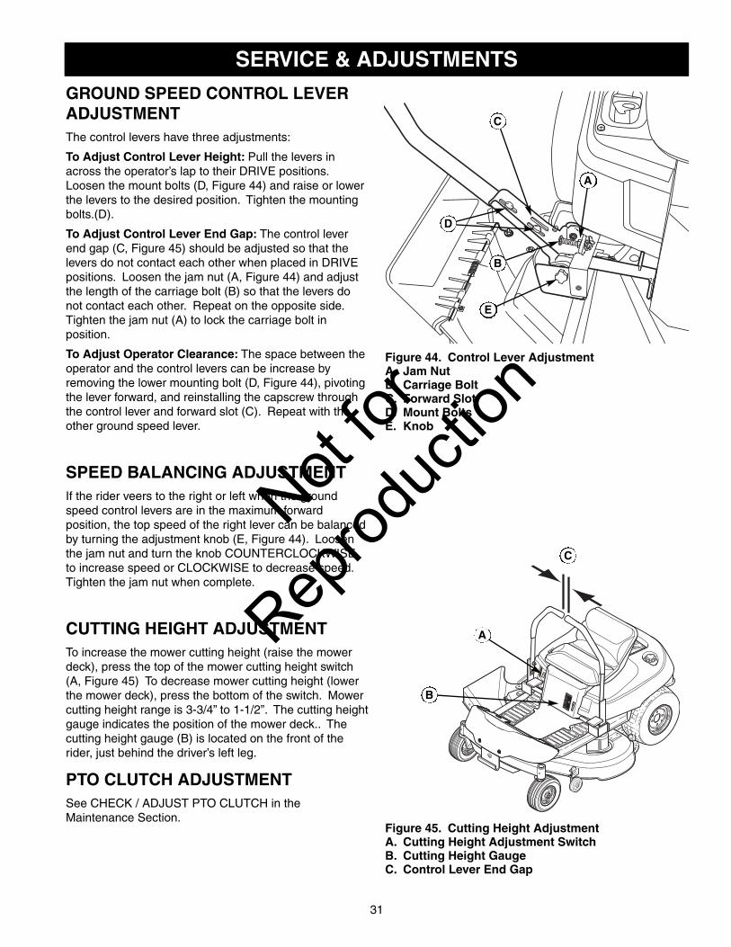
GROUND SPEED CONTROL LEVERADJUSTMENTThe control levers have three adjustments:
To Adjust Control Lever Height: Pull the levers inacross the operator’s lap to their DRIVE positions.Loosen the mount bolts (D, Figure 44) and raise or lowerthe levers to the desired position. Tighten the mountingbolts.(D).
To Adjust Control Lever End Gap: The control leverend gap (C, Figure 45) should be adjusted so that thelevers do not contact each other when placed in DRIVEpositions. Loosen the jam nut (A, Figure 44) and adjustthe length of the carriage bolt (B) so that the levers donot contact each other. Repeat on the opposite side.Tighten the jam nut (A) to lock the carriage bolt inposition.
To Adjust Operator Clearance: The space between theoperator and the control levers can be increase byremoving the lower mounting bolt (D, Figure 44), pivotingthe lever forward, and reinstalling the capscrew throughthe control lever and forward slot (C). Repeat with theother ground speed lever.
SPEED BALANCING ADJUSTMENTIf the rider veers to the right or left when the groundspeed control levers are in the maximum forwardposition, the top speed of the right lever can be balancedby turning the adjustment knob (E, Figure 44). Loosenthe jam nut and turn the knob COUNTERCLOCKWISEto increase speed or CLOCKWISE to decrease speed.Tighten the jam nut when complete.
CUTTING HEIGHT ADJUSTMENTTo increase the mower cutting height (raise the mowerdeck), press the top of the mower cutting height switch(A, Figure 45) To decrease mower cutting height (lowerthe mower deck), press the bottom of the switch. Mowercutting height range is 3-3/4” to 1-1/2”. The cutting heightgauge indicates the position of the mower deck.. Thecutting height gauge (B) is located on the front of therider, just behind the driver’s left leg.
PTO CLUTCH ADJUSTMENTSee CHECK / ADJUST PTO CLUTCH in theMaintenance Section.
Figure 44. Control Lever AdjustmentA. Jam NutB. Carriage BoltC. Forward SlotD. Mount BoltsE. Knob
A
C
E
B
D
1733458Low Cut
1
4
3
2
High Cut
CuttingHeight
RAISEMOWER
LOWERMOWER1734276
Figure 45. Cutting Height AdjustmentA. Cutting Height Adjustment SwitchB. Cutting Height GaugeC. Control Lever End Gap
A
C
B
Not for
Reprod
uctio
n

BRAKE ADJUSTMENT 1. Stop the unit, turn the ignition OFF, set the ground
speed levers to START/PARK positions, set theparking brake lever to the ENGAGE position, and waitfor all moving parts to stop.
2. Locate the brake rod (A, Figure 46) and adjustmentnut (B).
3. Measure the parking brake spring. Its compressedlength, with the parking brake lever in the ENGAGEposition, should be 3-1/2” (8.89cm). Adjust the springlength by turning the adjustment nut (B), if necessary.
WARNING
Figure 46. Brake AdjustmentA. Brake RodB. Adjustment NutC. Return Spring (Removed for Illustration Only)D. Return Spring Hole
3-1/2" (8.89cm)
A
B
C
D
Corrosion hazard.
Batteries contain acid. Always keep thebattery upright and do not spill theelectrolyte. Avoid contact with skin andeyes.
Explosion hazard.
Changing the battery produces explosivehydrogen gas. Only charge the battery in awell ventilated area, away from any ignitionsource such as a water heater, electricmotor, or a lit cigarette.
Wear Protective Equipment
Always wear gloves and safety glasseswhen handling the battery and batterycables.
BATTERY CHARGINGA dead battery or one too weak to start the engine maybe the result of a defect in the charging system or otherelectrical component. If there is any doubt about thecause of the problem, contact your local dealer. If youneed to replace the battery, follow the steps underCleaning the Battery & Cables in the RegularMaintenance Section.
To charge the battery, follow the instructions provided bythe battery charger manufacturer as well as all warningsincluded in the safety rules sections of this book. Chargethe battery until fully charged (until the specific gravity ofthe electrolyte is 1.250 or higher and the electrolytetemperature is at least 60° F). Do not charge at a ratehigher than 10 amps.
ENGINE ADJUSTMENTSThe engine is designed to deliver the correctperformance under all operating conditions. Anyadjustments must be performed by your local authorizeddealer.
32
Not for
Reprod
uctio
n

33
Figure 47. Measure Blade Tips to GroundA. Mower DeckB. Blade TipC. Level Ground
A
B
C
Figure 48. Orient Blades Side-to-Side
MOWER DECK LEVELING ADJUSTMENTS
Side to Side Leveling - 33” DecksIf the cut is uneven, the mower may need leveling.Unequal or improper tire pressure may also cause anuneven cut. See CHECK TIRE PRESSURE.
1. With the mower installed, place the rider on asmooth, level surface such as a concrete floor. Turnthe front wheels straight forward. Turn the engine off,set the ground speed control levers to START/PARK,set the parking brake lever to ENGAGE, and wait forall moving parts to stop.
2. Check for bent blades and replace if necessary.
3. Check the tire pressures. See CHECK TIREPRESSURE.
4. Set the cutting height to mid position. Arrange themower blade so that it is pointing from side-to-side(Figure 48).
5. Measure the distance between the tips of the bladeand the ground (Figures 47 & 48). If there is morethan 1/8" (3mm) difference between themeasurements on each side, proceed to step 6. If thedifference is 1/8" (3mm) or less, proceed to Front ToBack Leveling.
6. See Figure 49. Side-to-side leveling is accomplishedusing the threaded rods (A, Figure 49) and trunnion(B) on the right and left rear sides of the mower deck.Loosen the jam nuts (C) and adjust the nuts up ordown to adjust the mower level. When complete,tighten the jam nuts against the trunnion to lock theadjustment in place.
WARNINGBefore inspecting or adjusting the mower, turnthe mower blades OFF, turn the ignition switchOFF, and allow all moving parts to stop. Removeignition key, then disconnect the spark plug wireand fasten it away from the spark plug.
Figure 49. Side-to-Side AdjustmentA. Threaded RodB. TrunnionC. Jam Nuts
B
C
A
Not for
Reprod
uctio
n

34
Figure 50. Measure Blade Tips to GroundA. Mower DeckB. Blade TipC. Level Ground
A
B
C
Figure 51. Orient Blades Side-to-Side
MOWER DECK LEVELING ADJUSTMENTS
Side to Side Leveling - 42” & 52” DecksIf the cut is uneven, the mower may need leveling.Unequal or improper tire pressure may also cause anuneven cut. See CHECK TIRE PRESSURE.
1. With the mower installed, place the rider on asmooth, level surface such as a concrete floor. Turnthe front wheels straight forward. Turn the engine off,set the ground speed control levers to PARK, set theparking brake lever to ENGAGE, and wait for allmoving parts to stop.
2. Check for bent blades and replace if necessary.
3. Check the tire pressures. See CHECK TIREPRESSURE.
4. Set the cutting height to mid position. Arrange themower blades so that they are pointing from side-to-side (Figure 51).
5. Measure the distance between the tips of the outsideblades and the ground (Figures 50 & 51). If there ismore than 1/8" (3mm) difference between themeasurements on each side, proceed to step 6. If thedifference is 1/8" (3mm) or less, proceed to Front ToBack Leveling.
6. See Figure 52. Side-to-side leveling is accomplishedusing the threaded rods (A) and trunnion (B) on theright and left rear sides of the mower deck. Loosenthe jam nuts (C) and adjust the nuts up or down toadjust the mower level. When complete, tighten thejam nuts against the trunnion to lock the adjustmentin place.
WARNINGBefore adjusting the mower, turn the mowerblades OFF, turn the ignition switch OFF, removethe key, and allow all moving parts to stop.Disconnect the spark plug wire and fasten it awayfrom the spark plug.
Figure 52. Side-to-Side Adjustment (52” deck shown;42” deck similar)A. Threaded RodB. TrunnionC. Jam Nuts
42” Deck
52” Deck
A
C
C
B
Not for
Reprod
uctio
n
35
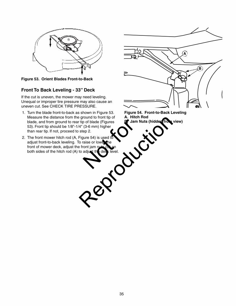
Figure 53. Orient Blades Front-to-Back
Front To Back Leveling - 33” DeckIf the cut is uneven, the mower may need leveling.Unequal or improper tire pressure may also cause anuneven cut. See CHECK TIRE PRESSURE.
1. Turn the blade front-to-back as shown in Figure 53.Measure the distance from the ground to front tip ofblade, and from ground to rear tip of blade (Figures53). Front tip should be 1/8"-1/4" (3-6 mm) higherthan rear tip. If not, proceed to step 2.
2. The front mower hitch rod (A, Figure 54) is used toadjust front-to-back leveling. To raise or lower thefront of mower deck, adjust the front jam nuts (C) onboth sides of the hitch rod (A) to adjust the deck level.
Figure 54. Front-to-Back LevelingA. Hitch RodB. Jam Nuts (hidden from view)
B
A
Not for
Reprod
uctio
n
36
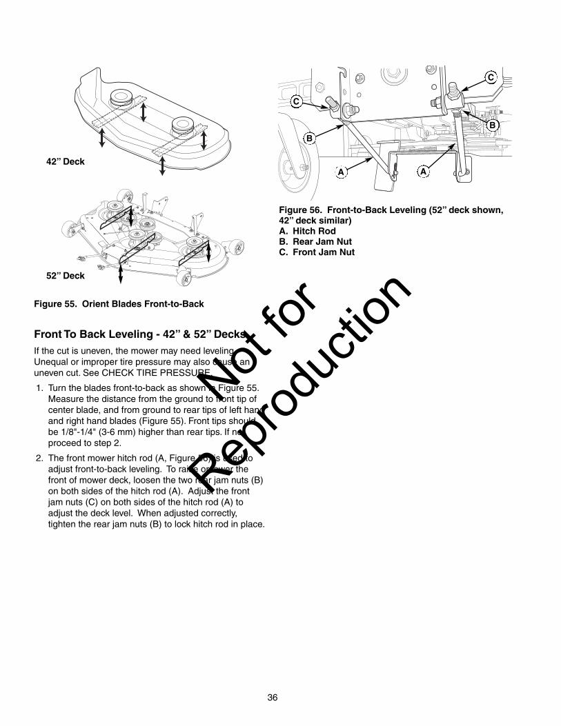
Figure 55. Orient Blades Front-to-Back
Front To Back Leveling - 42” & 52” DecksIf the cut is uneven, the mower may need leveling.Unequal or improper tire pressure may also cause anuneven cut. See CHECK TIRE PRESSURE.
1. Turn the blades front-to-back as shown in Figure 55.Measure the distance from the ground to front tip ofcenter blade, and from ground to rear tips of left handand right hand blades (Figure 55). Front tips shouldbe 1/8"-1/4" (3-6 mm) higher than rear tips. If not,proceed to step 2.
2. The front mower hitch rod (A, Figure 56) is used toadjust front-to-back leveling. To raise or lower thefront of mower deck, loosen the two rear jam nuts (B)on both sides of the hitch rod (A). Adjust the frontjam nuts (C) on both sides of the hitch rod (A) toadjust the deck level. When adjusted correctly,tighten the rear jam nuts (B) to lock hitch rod in place.
Figure 56. Front-to-Back Leveling (52” deck shown,42” deck similar)A. Hitch RodB. Rear Jam NutC. Front Jam Nut
42” Deck
52” Deck
A
C
B
A
C
B
Not for
Reprod
uctio
n

37
MOWER BELT REPLACEMENT
Mower Drive Belt Replacement - 33” Decks1. Park the rider on a level surface. Disengage the PTO,
turn off the engine, set the ground speed controllevers to START/PARK, and set the parking brakelever to ENGAGE. Remove the key.
2. Pull the idler pulley (C, Figure 57) to release belttension and remove the mower drive belt (B) from thePTO pulley (A).
3. Remove the belt from the remaining deck pulleys.Note: The left rear threaded rod must be removedfrom the mower in order to completely remove thebelt. Refer to the section entitled ‘Mower DeckRemoval and Installation’.
4. Install the new belt (B) as shown in Figure 57.
Mower Drive Belt Replacement - 42” Decks1. Park the rider on a level surface. Disengage the PTO,
turn off the engine, set the ground speed controllevers to START/PARK, and set the parking brakelever to ENGAGE. Remove the key.
2. Use the idler pulley arm (C, Figure 58) to release belttension and remove the mower drive belt (A) from thePTO pulley (E).
3. Remove the belt from the remaining deck pulleys.Note: It is not necessary to remove the mower deck.
4. Install the new belt (A) as shown in Figure 58.
WARNINGBefore inspecting or servicing the mower, turn themower blades OFF, turn the ignition switch OFF,and allow all moving parts to stop. Removeignition key, then disconnect the spark plug wireand fasten it away from the spark plug.
E
F
F
DC
B
A
Figure 58. Mower Belt Routing - 42” DecksA. Mower Drive BeltB. Right Arbor PulleyC. Idler Pulley ArmD. Left Arbor Pulley E. Engine PTO Pulley F. Backside Idler Pulley
A
B
C
D
Figure 57. Mower Belt Routing - 33” DecksA. Engine PTO PulleyB. Mower Drive BeltC. Back-Side Idler PulleyD. Stationary Idler PulleyE. Arbor Pulley
E
Not for
Reprod
uctio
n

38
Mower Drive Belt Replacement - 52” Decks1. Park the rider on a level surface. Disengage the PTO,
turn off the engine and set the ground speed controllevers to PARK. Remove the key.
2. Remove belt covers.
3. Insert ratchet into 3/8” (9.5 mm) square hole in idlerpulley arm (A, Figure 59) and pull to release belttension.
4. Remove the mower drive belt (B) from the enginedrive pulley (C).
5. Remove the belt from the remaining deck pulleys.
NOTE: It is not necessary to remove the mower deckto replace the belt.
6. Install the new mower belt as shown in Figure 59.
Arbor Drive Belt ReplacementContact your local authorized dealer for replacement ofthe arbor drive belt (A, Figure 59).
Figure 59. Mower Belt Routing - 52” DecksA. Idler Pulley ArmB. Mower BeltC. Engine Drive PulleyD. Fixed Idler Pulley (2)E. Arbor Drive Pulley (3)F. Adjustable Tension Idler Pulley
A
C
D
E
E
E D F B
MOWER DECK WASHOUT PORT(52” decks only)NOTE: The washout port allows you to connect a typicalgarden hose to the trim side (L.H.) of the mower deck toremove grass and debris from the underside. Thisensures proper and safe operation of the mower.
1. Place the lawn tractor on a smooth level surface.
Figure 60. Mower Deck Washout Port A. Quick DisconnectB. HoseC. Washout Port
WARNINGBefore running the mower, make sure the hose isproperly connected and does not come into contactwith the blades. When the mower is running and theblades are engaged, the person cleaning the mowerdeck must be in the operator position, and there areno bystanders. Failure to follow these precautionsmay result in serious injury or death.
2. Attach the quick disconnect (A, Figure 60) to gardenhose (B) and connect to washout port (C) on mowerdeck.
3. Turn the mower on and place in the highest cuttingposition.
4. Run water to remove grass and debris fromunderside of mower deck.
5. Turn the mower off.
6. Remove the garden hose and quick disconnect fromthe washout port when completed.
B
C
A
Not for
Reprod
uctio
n

39
STORAGE
WARNINGNever store the unit (with fuel) in an enclosed,poorly ventilated structure. Fuel vapors cantravel to an ignition source (such as a furnace,water heater, etc.) and cause an explosion.
Fuel vapor is also toxic to humans and animals.
STORAGEBefore StorageBefore you store your unit for the off-season, read theMaintenance and Storage instructions in the SafetyRules section, then perform the following steps:
• Turn the mower blades OFF, set the ground speedcontrol levers to START / PARK, set the parking brakelever to ENGAGE, and remove the key from theignition switch.
• Check all fluid levels. Check all maintenance items.
• Battery life will be increased if it is removed, put in acool, dry place and fully charged about once amonth. If the battery is left in the unit, disconnect thenegative cable.
It is important to prevent gum deposits from forming inthe essential fuel system parts such as the carburetor,fuel filter, fuel line, and fuel tank during storage. Also,alcohol blended fuels (called gasohol or using ethanol ormethanol) can attract moisture which leads to theseparation and formation of acids during storage. Acidic
gas can damage the fuel system of an engine while instorage.
To avoid engine problems use fuel stabilizer, especiallybefore storage of 30 days or longer.
After StorageBefore starting the unit after it has been stored:
• Check all fluid levels. Check all maintenance items.
• Fill with FRESH fuel.
• After starting, allow the engine to warm beforeoperating.
Not for
Reprod
uctio
n

40
TROUBLESHOOTINGWhile normal care and regular maintenance will extendthe life of your equipment, prolonged or constant usemay eventually require that service be performed to allowit to continue operating properly. The troubleshootingguide below lists the most common problems, theircauses and remedies.
If you prefer, all of these procedures can be performedby your local authorized dealer.
WARNINGTo avoid serious injury, perform maintenance onthe rider or mower only when the engine isstopped, the ground speed levers are set toSTART/PARK, and the parking brake lever is set toENGAGE. Always remove the ignition key, disconnect thespark plug wire and fasten it away from the plugbefore beginning the maintenance, to preventaccidental starting of the engine.
Troubleshooting the Rider
PROBLEM CAUSE REMEDY
Engine willnot turnover.
Ignition switch not turned fully to START position. Turn ignition switch fully to START position.
Ground speed levers not set to START/PARK. Set to START/PARK.
Mower blade switch in ON position. Place in OFF position.Parking brake lever in DISENGAGE position. Set to ENGAGE position.
Battery terminals require cleaning. Clean the battery terminals
Battery discharged or dead. Recharge or replace.
Wiring loose or broken; connector separated. Visually check wiring & replace broken or frayedwires. Tighten loose connections.
Safety interlock switch faulty. Replace. Contact your local authorized dealer.
Solenoid or starter motor faulty. Replace. Contact your local authorized dealer.
Engine willturnover butwill not start.
Engine is cold; choke not in CLOSED position. Move choke to CLOSED position.
Engine is warm; choke not in OPEN position. Move choke to OPEN position.
Engine flooded. Set choke to OPEN position when cranking engine.
Out of fuel. Allow engine to cool, then refill the fuel tank.
Fuel is old or stale, or water in fuel. Drain fuel & replace with fresh fuel. Contact yourlocal authorized dealer.
Spark plug(s) faulty, fouled or incorrectly gapped. Clean and gap or replace.
Safety interlock switch faulty. Replace. Contact your local authorized dealer.
Engine startshard or runspoorly.
Air filter plugged Service pre-cleaner and/or replace air filterelement.
Choke not set to CLOSED position whencranking the engine, OR choke not set to OPENafter engine starts.
Set choke to CLOSED when cranking. Set choketo OPEN when engine is running. A warm enginemay not require choking.
Spark plug faulty, fouled, or incorrectly gapped. Clean and gap or replace.
Engineknocks.
Low oil level. Check/add oil as required.
Using wrong grade oil. See "Change Engine Oil" in the MaintenanceSection.
Excessive oilconsumption.
Engine running too hot. Clean engine cooling fins, blower screen and aircleaner.
Using wrong weight oil. See "Change Engine Oil" in the MaintenanceSection.
Too much oil in crankcase. Drain excess oil.
Engineexhaust isblack.
Dirty air filter or pre-cleaner, or both. Service or replace as required. See MaintenanceSection.
Choke set to CLOSED when engine is running. Set choke to OPEN as soon as engine starts.
Not for
Reprod
uctio
n

41
Troubleshooting the MowerPROBLEM CAUSE REMEDY
Mower cuttingheight does notadjust.
Cutting height motor screw dirty or requireslube.
Thoroughly clean and lubricate cutting height motorscrew.
Cutting height linkage disconnected. Check that mower linkage is connected.
Mower cut isuneven.
Rider tires not inflated equally or properly. See Maintenance Section.
Mower not leveled properly. See "Mower Leveling" in Service & Adjustments.
Mower cut isrough looking.
Engine speed too slow. Always set engine speed to FAST when mowing.
Ground speed too fast. Decrease ground speed.
Blades are dull. Sharpen or replace blades. See MaintenanceSection.
Mower drive belt slipping because it is oily orworn.
Clean or replace belt as necessary.
Blades not properly fastened to arbors. See "Check/Replace Mower Blades" in MaintenanceSection.
Engine stallseasily withmower engaged.
Engine speed too slow. Always set engine speed to FAST when mowing.
Ground speed too fast. Decrease Ground Speed.
Cutting height set too low. Cut tall grass at maximum cutting height during firstpass.
Underside of mower deck dirty. Remove mower deck and clean underside.
Discharge chute jamming with cut grass. Cut grass with discharge pointing toward previouslycut area.
Excessivemowervibration.
Blade mounting nuts are loose. Torque as per instructions. See MaintenanceSection.
Mower blades, arbors, or pulleys are bent. Check and replace as necessary.
Mower blades are out of balance. Replace or balance blades. See MaintenanceSection.
Belt installed incorrectly. Reinstall correctly.
Mower drive beltslips or fails todrive.
Idler pulley spring broken or not properlyattached.
Repair or replace as needed.
Mower drive belt broken. Replace drive belt.
PTO clutch out of adjustment. Adjust PTO clutch. See Maintenance Section.
Engine runs, butrider will notdrive.
Transmission release levers in PUSHpositions.
Move levers to DRIVE positions.
Drive belt slips. Clean or replace belt as necessary.
Belt is broken. Replace drive belt. Contact your local authorized dealer.
Parking brake is not fully released. Contact your local authorized dealer.
Parking brakewill not hold.
Parking brake is incorrectly adjusted. See Service & Adjustments Section.
Rider steers orhandles poorly.
Improper tire inflation. See Maintenance Section.
Steering linkage is loose. Check and tighten any loose connections.
Rider tracks toone side.
Ground speed adjustment knobs notadjusted.
See SPEED BALANCING ADJUSTMENT in Service &Adjustments section.
Not for
Reprod
uctio
n

42
SPECIFICATIONS
ENGINE (18.5HP):Make Briggs & StrattonModel ELSHorsepower 18.5 @ 3600 rpmDisplacement 30.59 Cu. in (500cc)
ENGINE (21HP):Make Briggs & StrattonModel ELSHorsepower 21 @ 3600 rpmDisplacement 30.59 Cu. in (500cc)
ENGINE (26HP):Make Briggs & StrattonModel ELSHorsepower 26 @ 3600 rpmDisplacement 44.2 Cu. in (725cc)
CHASSIS:Fuel Tank Cap. Capacity: 4.00 Gallons (15,14 L)Rear Wheels Tire Size: 18 x 8.5 -8
Inflation Pressure: 10-12 psi (,69-,83 bar)Front Wheels Tire Size: 11 x 4-5
Inflation Press.: 18-20 psi (1,24-1,30 bar)
TRANSMISSION:Type Hydro-Gear EZT ZC-AHBB-2A7B-1DPXHydraulic Fluid 20w 50 Premium Engine Oil Continuous Torque 115 ft. lbs.OutputMaximum Weight 340 lbs per Axle
NOTE: Specifications are correct at time of printing and are subject to change without notice.
The gross power rating for individual gas engine models is labeled in accordance with SAE (Society of Automotive Engineers)code J1940 (Small Engine Power & Torque Rating Procedure), and rating performance has been obtained and corrected inaccordance with SAE J1995 (Revision 2002-05). Torque values are derived at 3060 RPM; horsepower values are derived at 3600RPM. Actual gross engine power will be lower and is affected by, among other things, ambient operating conditions and engine-to-engine variability. Given both the wide array of products on which engines are placed and the variety of environmental issuesapplicable to operating the equipment, the gas engine will not develop the rated gross power when used in a given piece of powerequipment (actual "on-site" or net horsepower). This difference is due to a variety of factors including, but not limited to,accessories (air cleaner, exhaust, charging, cooling, carburetor, fuel pump, etc.), application limitations, ambient operatingconditions (temperature, humidity, altitude), and engine-to-engine variability. Due to manufacturing and capacity limitations, Briggs& Stratton may substitute an engine of higher rated power for this Series engine.Not
for
Reprod
uctio
n
43
SERVICE ITEMS
Replacement PartsReplacement parts are available from your authorizeddealer. Always use genuine Simplicity or SnapperService Parts.
Technical ManualsAdditional copies of this manual are available, as well asfully illustrated parts lists. These manuals show all of theproduct’s components in exploded views (3D illustrationswhich show the relationship of parts and how they gotogether) as well as part numbers and quantities used.Important assembly notes and torque values are alsoincluded.
For applicable manuals currently available for yourmodel, contact our Customer Publications Department at877-249-6647. Have the information listed in the box atleft available when phoning in your request. Technicalmanuals can be downloaded from
www.simplicitymfg.com
www.snapper.com
Engine OilTouch-Up PaintGrease Gun Kit 8 oz. Grease Tube
Tire SealantDegrimer/DegreaserGas Stabilizer
Maintenance ItemsMany convenient and helpful service and maintenanceitems are available from you authorized dealer. Some ofthese items include:
Model:
Mfg. No.:
Your Name:
Address:
City, State, Zip:
Visa/Mastercard No.:
Card Expiration Date:
Not for
Reprod
uctio
n

44
NOTES
Not for
Reprod
uctio
n

45
NOTES
Not for
Reprod
uctio
n

46
Lawn Care& Mowing Information
LC-1
HOW AND WHEN TO
WATER, FERTILIZE &
AERATE
Most lawns are watered too often,
but with too little water. Howevertoo much water can allow develop-ment of diseases with your lawn. It isbest to water the lawn only when
necessary, and then to water it
slowly, evenly, and deeply—imitat-
ing a slow, soaking rain.
WHEN TO WATER YOUR LAWN
When the lawn begins to wilt, the grass’s color dulls, orfootprints stay compressed for more than a few seconds,the lawn is beginning to dry out, and needs additionalmoisture. The best time to water is early morning to allowthe water to soak deeply into the lawn and reduce theamount that evaporates in the hot afternoon sun.
HOW TO WATER YOUR LAWN
The best method of watering a lawnis to imitate a slow, soaking rain,applying about 1 inch of water. HOW TO FERTILIZE YOUR LAWN
Fertilizing with a slow-release fertiliz-er provides missing nutrients whichhelp create slow, even growth.Remember that over-fertilizing cancause harm, and that most fertilizingshould be applied in the spring sothat it will release into the lawnthrough the summer.
AERATING YOUR LAWN
Consider aerating your lawn in spring. Using an aeratorto remove cores of soil from the lawn increases thespeed of clipping decomposition and encourages deeperroot growth by opening up the soil and permitting greatermovement of water, fertilizer and air.
TP 600-2136-03-UV-SMA
HOW HIGH TO MOW THE GRASS
Cutting the grass too short causes weak, thingrass plants, which are easily damaged by dryperiods and pests.
Letting grass grow a bit longer—especially when itis hot and dry—reduces heat build-up, preservesneeded moisture and protects the grass from heatdamage and other problems.
Cutting off too much at one time shocks the plant’sgrowth system and weakens the grass plants. Agood rule of thumb is the 1/3 rule: to cut no
more than one third of the grass height, and
never more than 1 inch at a time.
Cut
Here On
Second
Pass
Cut Here On
First Pass
Optimal
cutting point
at less than
1/3 from top
of grass blade
Tall Grass Requires Incremental Cutting
For extremely tall grass, set the cutting height at maxi-mum for the first pass, and then reset it to the desiredheight and mow a second or third time.
Don’t cover the grass surface with a heavy layer ofclippings.
Cutting down to thisarea contributes tothatch problems
Cut less than1/3Not
for
Reprod
uctio
n

47LC-2
Lawn Care & Mowing Information
WHEN AND HOW OFTEN TO MOWThe time of day and condition of the grass greatly affect the results you’llget when mowing. For the best results, follow these guidelines:� Mow when the grass is between 3”-4” (7,5-10 cm) high.
� Mow with sharp blades. Short clippings of grass one inch or shorterdecompose more quickly than longer blades. Sharp mower blades cutgrass cleanly and efficiently, preventing frayed edges which harm thegrass.
� Mow at time of day when the grass is cool and dry. Late afternoon orearly evening often provide these ideal mowing conditions.
� Avoid mowing after rain or even heavy dew, and never mulch when thegrass is wet (moist grass does not mulch well, and clumps beneath themower deck).
Note: Always operate the engine at full throttle when mowing.
PROPER MOWING SPEED
ENGINE SPEED & GROUND SPEED
Always operate the engine at full throttle when mowing.If you hear the engine slowing down, you are mowing toofast—maintaining a slower ground speed will improve thecutting efficiency of the blades and prevents many com-mon cutting problems.
Select an appropriate ground speed for the thicknessand height of the grass you are cutting (3rd gear or slow-er for manual gear models, or mid-range or slower forhydro models). If you hear the engine slowing down youare mowing too fast, use a slower ground speed.
HOW MUCH GRASS TO CUT OFF
Mow when the grass is 3”-4” inches (7,5-10cm) long. Donot cut off more that 1” (2.5cm) of grass in a single pass.
Not for
Reprod
uctio
n

MANUFACTURING, INC.500 N Spring Street / PO Box 997Port Washington, WI 53074-0997
www.SimplicityMfg.com
Briggs & Stratton Yard Power Products Group Copyright © 2009 Briggs & Stratton Power Products Group, LLCMilwaukee, WI USA. All Rights Reserved
PRODUCTS, INC.535 Macon StreetMcDonough, GA 30253
www.Snapper.com
Not for
Reprod
uctio
n