Embed Size (px)
Citation preview

MT-030-60-E
Use with Model Number:TC-030-60
Operator’s Manual
The best way to go about your business
Model TC-30, TC-40. TC-50, TC60
Serial Number Range: Starting: 210000 Ending: See Introduction Chapter
READ THIS MANUAL BEFORE OPERATION OR PERFORMING MAINTENANCE.This manual contains important information regarding the safe operation and maintenance of this vehicle. This manual shall be kept with the vehicle.
WARNING
Shown with optional OPS
B
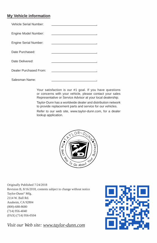
Your satisfaction is our #1 goal. If you have questions or concerns with your vehicle, please contact your sales Representative or Service Advisor at your local dealership.Taylor-Dunn has a worldwide dealer and distribution network to provide replacement parts and service for our vehicles.Refer to our web site, www.taylor-dunn.com, for a dealer lookup application.
Originally Published 7/24/2018Revision B, 8/16/2018, contents subject to change without noticeTaylor-Dunn® Mfg.2114 W. Ball Rd. Anaheim, CA 92804 (800)-688-8680(714) 956-4040 (FAX) (714) 956-0504
Visit our Web site: www.taylor-dunn.com
My Vehicle information
Vehicle Serial Number: .
Engine Model Number: .
Engine Serial Number: .
Date Purchased: .
Date Delivered: .
Dealer Purchased From: .
Salesman Name: .
Page 3Tiger TC-3060 Operator Manual
MT-030-60-E
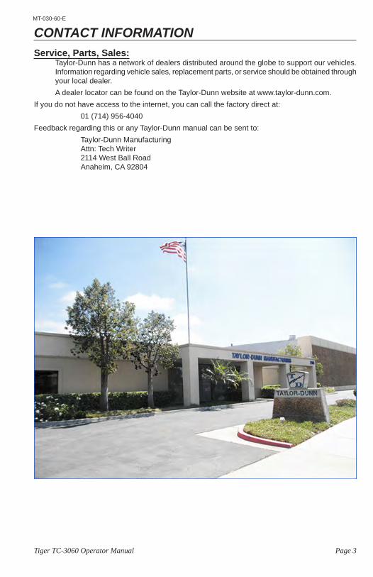
CONTACT INFORMATIONService, Parts, Sales:
Taylor-Dunn has a network of dealers distributed around the globe to support our vehicles. Information regarding vehicle sales, replacement parts, or service should be obtained through your local dealer. A dealer locator can be found on the Taylor-Dunn website at www.taylor-dunn.com.
If you do not have access to the internet, you can call the factory direct at:01 (714) 956-4040
Feedback regarding this or any Taylor-Dunn manual can be sent to:Taylor-Dunn ManufacturingAttn: Tech Writer2114 West Ball RoadAnaheim, CA 92804
Page 4 Tiger TC-3060 Operator Manual
MT-030-60-E
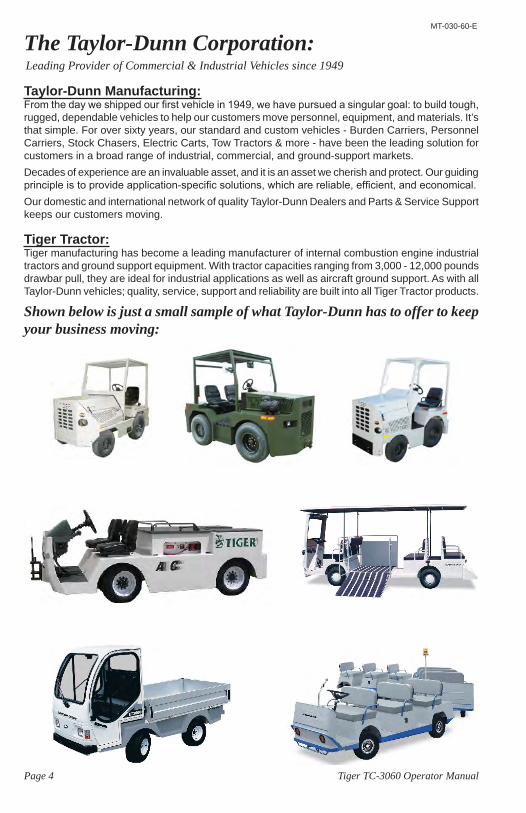
The Taylor-Dunn Corporation:Leading Provider of Commercial & Industrial Vehicles since 1949
Taylor-Dunn Manufacturing:From the day we shipped our first vehicle in 1949, we have pursued a singular goal: to build tough, rugged, dependable vehicles to help our customers move personnel, equipment, and materials. It’s that simple. For over sixty years, our standard and custom vehicles - Burden Carriers, Personnel Carriers, Stock Chasers, Electric Carts, Tow Tractors & more - have been the leading solution for customers in a broad range of industrial, commercial, and ground-support markets.Decades of experience are an invaluable asset, and it is an asset we cherish and protect. Our guiding principle is to provide application-specific solutions, which are reliable, efficient, and economical.Our domestic and international network of quality Taylor-Dunn Dealers and Parts & Service Support keeps our customers moving.
Tiger Tractor:Tiger manufacturing has become a leading manufacturer of internal combustion engine industrial tractors and ground support equipment. With tractor capacities ranging from 3,000 - 12,000 pounds drawbar pull, they are ideal for industrial applications as well as aircraft ground support. As with all Taylor-Dunn vehicles; quality, service, support and reliability are built into all Tiger Tractor products.
Shown below is just a small sample of what Taylor-Dunn has to offer to keep your business moving:
Page 5Tiger TC-3060 Operator Manual
MT-030-60-E
Table of ContentsContact Information ......................3The Taylor-Dunn Corporation: ....4
Introduction 7Who Should Read This Manual ........... 7About This Manual ............................... 7
Glossary of Terms ...........................8Conventions ....................................9
Signal Words and Their Definitions: ..... 9Safety Alert Message ........................... 9
Responsibilities ...............................10Of the Owner... ..................................... 10Of the Operator... ................................. 10Of the Passengers ... ........................... 10Of the Service Personnel... .................. 10
Vehicle Modifications .....................11Replacement Parts .........................12
Using Non-Taylor-Dunn Replacement Components ......................................... 12
About Your Vehicle 13Licensing Requirements ...................... 13
How to Identify Your Vehicle ........14Data Plate ............................................ 14Where to Find Data Plate and Serial Number ................................................ 14
How to Identify Your Engine & Transmission ...................................15
Taking Delivery of Your Vehicle 16
If a Problem is Found ....................16
Operator Training 17Driver Qualifications ............................. 17
Vehicle Controls 191: Ignition Switch .................................. 192: Headlight Switch .............................. 193: Engine Oil Pressure ......................... 19
6: Battery Volt Meter ............................ 197: Fuel Gauge ...................................... 198: Engine Hour Meter ........................... 191: Throttle Pedal ................................... 202: Foot Brake Pedal ............................. 203: Parking Brake .................................. 204: Shift Lever ........................................ 20Directional Signals ............................... 20Hazard Light Switch ............................. 20Steering ............................................... 21Horn Switch .......................................... 21Operator Presence Switch) .................. 21Transmission Shift Levers .................... 22
Vehicle Operation 23General Safety Guidelines ................... 23Seat Belts (optional) ............................. 25All Seat Belt Types ............................... 26Combination Lap and Shoulder Belts .. 26Lap Belts Only ...................................... 26Seat Belts While Pregnant ................... 26Seat Belt Maintenance ......................... 26Starting the Engine .............................. 27Diesel: .................................................. 27Refueling .............................................. 28Stopping the Engine ............................. 28Jump Starting ....................................... 29Driving .................................................. 30Collisions or Accidents ......................... 32
Towing 33Draw Bar Pull (DBP), Definition ........... 33Towing the Vehicle ............................... 34
Engine Fuel 35
Approved Fuels...............................36Gasoline ............................................... 36Gasohol ................................................ 36LPG ...................................................... 36Diesel ................................................... 36
Refueling .........................................37
Storing and Returning to Service 37
Page 6 Tiger TC-3060 Operator Manual
MT-030-60-E
Vehicle Maintenance 38Daily Inspection .................................... 38Pre-Operation Inspection ..................... 38
Interlock Switch Inspection ...........39Shift Lever Interlock ............................. 39Seat Interlock ....................................... 39Brake Shift Interlock ............................. 39Maintenance Schedule ........................ 40Maintenance Guidelines for Severe Duty Applications .......................................... 40
Fluid Levels .....................................41Engine Oil ............................................ 41Engine Coolant .................................... 41Engine Dipstick Locations .................... 42Coolant Specifications ......................... 44Transmission Fluid ............................... 45Transmission Dipstick Locations .......... 46
Brake Fluid Level ...........................47Hydraulic Fluid (power steering) .......... 48
Air Filter .........................................49Air Filter Monitor ................................... 49
Circuit Breaker panel 50
Battery Maintenance 51Cleaning ............................................... 52Watering ............................................... 52Charging .............................................. 52
Tires .................................................53Air pressure .......................................... 53Tire Tread Wear ................................... 53Changing a Tire/Wheel assembly ........ 54Tire Rotation ......................................... 55Replacing a Tire ................................... 55
Cleaning ..........................................56Glass .................................................... 56Plastic Windows ................................... 56Seats / Soft Doors ................................ 56Interior .................................................. 56Exterior Body ....................................... 56Cleaning the Seat Belts ....................... 56Under Carriage .................................... 56Battery .................................................. 56
Standard Specifications 57Index 58
Page 7Tiger TC-3060 Operator Manual
MT-030-60-E
IntroductionWho Should Read This ManualThis manual is intended for use by anyone operating or performing routine maintenance on this vehicle. Each person shall be familiar with the parts of this manual that apply to their use of this vehicle.
About This ManualThis manual is valid only for the serial numbers listed on the front cover. If the ending serial number is blank, then this manual was for current production vehicles when printed. If you did not receive this manual with the vehicle, you should confirm this manual is valid for your serial number at the Taylor-Dunn web site. A place to record your vehicle information is provided on the inside front cover This manual is subject to change without notice. Updates are available through your dealer or the Taylor-Dunn web site at www.taylor-dunn.com.Taylor-Dunn is not to be held liable for errors in this manual or any consequential damage that results from the use of this manual.The purchase of this vehicle shows a belief in high quality products manufactured in the USA. Taylor-Dunn, a leading manufacturer of electric burden carriers, personnel carriers, and tow tractors since 1949, wants to be sure this vehicle provides years of reliable service. Please continue to read this manual and enjoy this high quality Taylor-Dunn vehicle.This manual is to serve as a guide for the operation and maintenance of your Taylor-Dunn vehicle. Taylor-Dunn has made every effort to include as much information as possible about the operation and maintenance of this vehicle.This manual contains information about the standard equipment and options available for this model. This vehicle may not be equipped with all available options. If you do not know which information applies to your vehicle, then you should contact your dealer.Included in this manual are:
• Vehicle Description• Safety Rules and Guidelines• Operational Information• Operator Responsibilities• Owner Responsibilities• Control Operation and Location Information• Maintenance Information
Before operating or performing maintenance on this or any other Taylor-Dunn vehicle, read the appropriate Taylor-Dunn manual. Please, be aware of all cautions, warnings, instructions, and notes contained in this manual.
The only personnel authorized to repair, modify, or adjust any part of this or any Taylor-Dunn vehicle is a factory authorized service technician. Repairs made by unauthorized personnel may result in damage to the vehicles systems which could lead to an unsafe condition resulting in severe bodily injury and/or property damage. Unauthorized repairs may also void the vehicles warranty.
WARNING
Page 8 Tiger TC-3060 Operator Manual
MT-030-60-E
Approved Opera to r Position
The operator shall be seated in the operator seat with back up against the operator seat back cushion. Additional back support may be added as needed. The back support shall be fastened to the operator seat back cushion to prevent it from falling off the vehicle or onto the seat cushion. The operator’s left foot shall be on the floorboard. The right foot should be positioned for easy access to the brake or throttle pedals. Both hands should be on the steering wheel while the vehicle is in motion.
Caution (signal word) Refer to Signal Words and Their Definitions.
Danger (signal word) Refer to Signal Words and Their Definitions.
DBP Draw Bar Pull (see below).
Draw bar pull The force seen by the trailer hitch at the rear of the vehicle.
Electrolyte The fluid inside of a battery.
LPG Liquefied Petroleum Gas, a fuel
Moderate injury An injury treatable by first aid and/or follow up treatment by a doctor or other professional medical personnel.
Notice (signal word) Refer to Signal Words and Their Definitions.
OPS “Operator Protective Structure”: Steel cab or cage around the occupants.
Seating position: When used in the context of occupant seating positions, “seat” is defined as a single seat cushion or a span of 20 inches on a bench seat.
Service Brake The primary braking system used to stop the vehicle.
Severe bodily injury An injury that requires immediate treatment by a doctor or other professional medical personnel. Not first aid.
Signal word A word used to define hazards to operator, passengers, service technician, or personnel in the immediate vicinity of the vehicle.
Small children Children that must be transported in a child seat as defined by federal or state motor vehicle standards.
Warning (signal word): Refer to Signal Words and Their Definitions.
GLOSSARY OF TERMSThere are a number of words and phrases used in this document that may have a different, special, or specific definition when use in the context of this document.
Page 9Tiger TC-3060 Operator Manual
MT-030-60-E
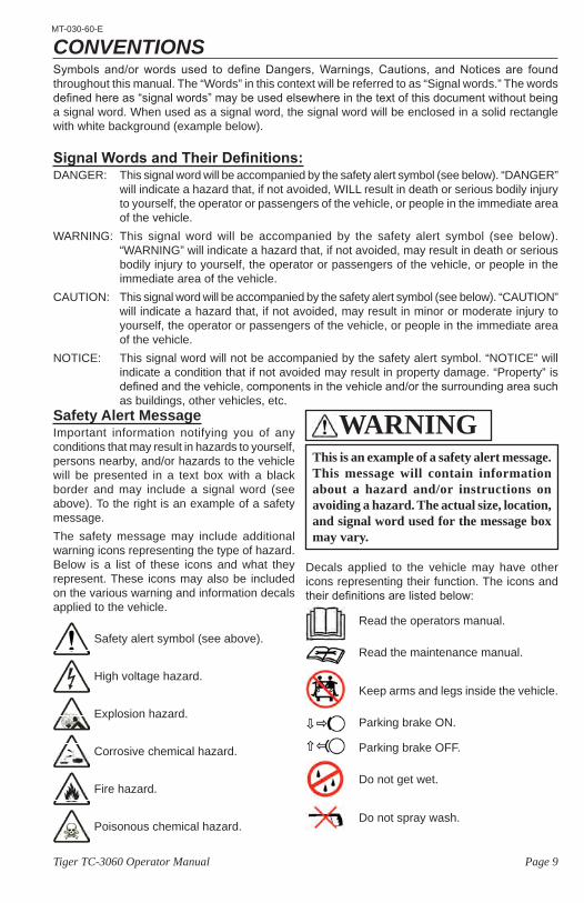
CONVENTIONSSymbols and/or words used to define Dangers, Warnings, Cautions, and Notices are found throughout this manual. The “Words” in this context will be referred to as “Signal words.” The words defined here as “signal words” may be used elsewhere in the text of this document without being a signal word. When used as a signal word, the signal word will be enclosed in a solid rectangle with white background (example below).
Signal Words and Their Definitions:DANGER: This signal word will be accompanied by the safety alert symbol (see below). “DANGER”
will indicate a hazard that, if not avoided, WILL result in death or serious bodily injury to yourself, the operator or passengers of the vehicle, or people in the immediate area of the vehicle.
WARNING: This signal word will be accompanied by the safety alert symbol (see below). “WARNING” will indicate a hazard that, if not avoided, may result in death or serious bodily injury to yourself, the operator or passengers of the vehicle, or people in the immediate area of the vehicle.
CAUTION: This signal word will be accompanied by the safety alert symbol (see below). “CAUTION” will indicate a hazard that, if not avoided, may result in minor or moderate injury to yourself, the operator or passengers of the vehicle, or people in the immediate area of the vehicle.
NOTICE: This signal word will not be accompanied by the safety alert symbol. “NOTICE” will indicate a condition that if not avoided may result in property damage. “Property” is defined and the vehicle, components in the vehicle and/or the surrounding area such as buildings, other vehicles, etc.
Safety alert symbol (see above).
High voltage hazard.
Explosion hazard.
Corrosive chemical hazard.
Fire hazard.
Poisonous chemical hazard.
Safety Alert MessageImportant information notifying you of any conditions that may result in hazards to yourself, persons nearby, and/or hazards to the vehicle will be presented in a text box with a black border and may include a signal word (see above). To the right is an example of a safety message.The safety message may include additional warning icons representing the type of hazard. Below is a list of these icons and what they represent. These icons may also be included on the various warning and information decals applied to the vehicle.
This is an example of a safety alert message. This message will contain information about a hazard and/or instructions on avoiding a hazard. The actual size, location, and signal word used for the message box may vary.
WARNING
Decals applied to the vehicle may have other icons representing their function. The icons and their definitions are listed below:
Read the operators manual.
Read the maintenance manual.
Keep arms and legs inside the vehicle.
Parking brake ON.
Parking brake OFF.
Do not get wet.
Do not spray wash.
Page 10 Tiger TC-3060 Operator Manual
MT-030-60-E
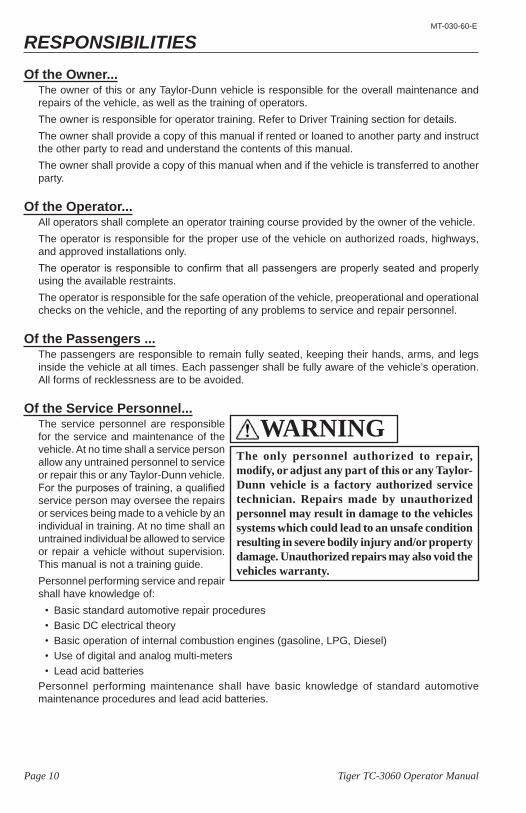
RESPONSIBILITIESOf the Owner...
The owner of this or any Taylor-Dunn vehicle is responsible for the overall maintenance and repairs of the vehicle, as well as the training of operators.The owner is responsible for operator training. Refer to Driver Training section for details.The owner shall provide a copy of this manual if rented or loaned to another party and instruct the other party to read and understand the contents of this manual.The owner shall provide a copy of this manual when and if the vehicle is transferred to another party.
Of the Operator...All operators shall complete an operator training course provided by the owner of the vehicle.The operator is responsible for the proper use of the vehicle on authorized roads, highways, and approved installations only.The operator is responsible to confirm that all passengers are properly seated and properly using the available restraints.The operator is responsible for the safe operation of the vehicle, preoperational and operational checks on the vehicle, and the reporting of any problems to service and repair personnel.
Of the Passengers ...The passengers are responsible to remain fully seated, keeping their hands, arms, and legs inside the vehicle at all times. Each passenger shall be fully aware of the vehicle’s operation. All forms of recklessness are to be avoided.
Of the Service Personnel...The service personnel are responsible for the service and maintenance of the vehicle. At no time shall a service person allow any untrained personnel to service or repair this or any Taylor-Dunn vehicle. For the purposes of training, a qualified service person may oversee the repairs or services being made to a vehicle by an individual in training. At no time shall an untrained individual be allowed to service or repair a vehicle without supervision. This manual is not a training guide.Personnel performing service and repair shall have knowledge of:
• Basic standard automotive repair procedures• Basic DC electrical theory• Basic operation of internal combustion engines (gasoline, LPG, Diesel)• Use of digital and analog multi-meters• Lead acid batteries
Personnel performing maintenance shall have basic knowledge of standard automotive maintenance procedures and lead acid batteries.
The only personnel authorized to repair, modify, or adjust any part of this or any Taylor-Dunn vehicle is a factory authorized service technician. Repairs made by unauthorized personnel may result in damage to the vehicles systems which could lead to an unsafe condition resulting in severe bodily injury and/or property damage. Unauthorized repairs may also void the vehicles warranty.
WARNING
Page 11Tiger TC-3060 Operator Manual
MT-030-60-E
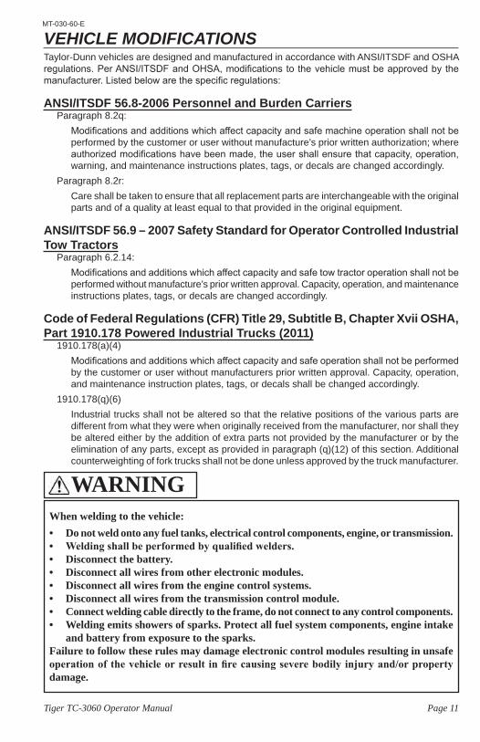
VEHICLE MODIFICATIONSTaylor-Dunn vehicles are designed and manufactured in accordance with ANSI/ITSDF and OSHA regulations. Per ANSI/ITSDF and OHSA, modifications to the vehicle must be approved by the manufacturer. Listed below are the specific regulations:
ANSI/ITSDF 56.8-2006 Personnel and Burden CarriersParagraph 8.2q:
Modifications and additions which affect capacity and safe machine operation shall not be performed by the customer or user without manufacture’s prior written authorization; where authorized modifications have been made, the user shall ensure that capacity, operation, warning, and maintenance instructions plates, tags, or decals are changed accordingly.
Paragraph 8.2r:Care shall be taken to ensure that all replacement parts are interchangeable with the original parts and of a quality at least equal to that provided in the original equipment.
ANSI/ITSDF 56.9 – 2007 Safety Standard for Operator Controlled Industrial Tow Tractors
Paragraph 6.2.14:Modifications and additions which affect capacity and safe tow tractor operation shall not be performed without manufacture’s prior written approval. Capacity, operation, and maintenance instructions plates, tags, or decals are changed accordingly.
Code of Federal Regulations (CFR) Title 29, Subtitle B, Chapter Xvii OSHA, Part 1910.178 Powered Industrial Trucks (2011)
1910.178(a)(4) Modifications and additions which affect capacity and safe operation shall not be performed by the customer or user without manufacturers prior written approval. Capacity, operation, and maintenance instruction plates, tags, or decals shall be changed accordingly.
1910.178(q)(6)Industrial trucks shall not be altered so that the relative positions of the various parts are different from what they were when originally received from the manufacturer, nor shall they be altered either by the addition of extra parts not provided by the manufacturer or by the elimination of any parts, except as provided in paragraph (q)(12) of this section. Additional counterweighting of fork trucks shall not be done unless approved by the truck manufacturer.
When welding to the vehicle:• Do not weld onto any fuel tanks, electrical control components, engine, or transmission. • Welding shall be performed by qualified welders.• Disconnect the battery.• Disconnect all wires from other electronic modules.• Disconnect all wires from the engine control systems.• Disconnect all wires from the transmission control module. • Connect welding cable directly to the frame, do not connect to any control components.• Welding emits showers of sparks. Protect all fuel system components, engine intake
and battery from exposure to the sparks.Failure to follow these rules may damage electronic control modules resulting in unsafe operation of the vehicle or result in fire causing severe bodily injury and/or property damage.
WARNING
Page 12 Tiger TC-3060 Operator Manual
MT-030-60-E
REPLACEMENT PARTS
Using Non-Taylor-Dunn Replacement ComponentsTo maintain peak performance, always use original Taylor-Dunn replacement parts intended for use on your vehicle.Taylor-Dunn components are designed and tested for use on specific Taylor-Dunn model vehicles. Only use the correct Taylor-Dunn replacement components for your Taylor-Dunn vehicle.
Electrical ComponentsElectrical components not tested by Taylor-Dunn (or intended for use on other Taylor-Dunn vehicles) may have unanticipated interaction and/or interference with the vehicle control systems resulting in unsafe vehicle operation or damage to the electrical system.
Mechanical ComponentsMechanical components not tested by Taylor-Dunn (or from other model Taylor-Dunn vehicles) may have an undesirable affect on the operation of the vehicle, result in additional frame stress, or stress other components resulting in premature failure or an unsafe condition.Due to the unknown properties of non-Taylor-Dunn tested components or from components not originally equipped on the vehicle, we cannot approve their use in a Taylor-Dunn vehicle.
To maintain peak performance, always use original Taylor-Dunn replacement parts intended for use on your vehicle. Taylor-Dunn components are designed and tested for use on specific Taylor-Dunn model vehicles. Only use the correct Taylor-Dunn replacement components for your Taylor-Dunn vehicle.Do not modify your vehicle:
Modifications to this vehicle may have an undesirable affect on the operation of the vehicle, result in additional frame stress, or stress other components resulting in premature failure or an unsafe condition and may lead to an accident resulting in serious injury or death.
WARNING
Page 13Tiger TC-3060 Operator Manual
MT-030-60-E
About Your VehicleThe purchase of your Taylor-Dunn vehicle shows a belief in high quality products manufactured in the USA.Taylor-Dunn, a leading manufacturer of electric burden and personnel carriers since 1949, wants to be sure this vehicle provides years of reliable service. Please continue to read this manual and enjoy this high quality Taylor-Dunn vehicle.Each base model is available in numerous configurations depending on what options were requested when the vehicle was ordered.
Licensing RequirementsThis vehicle IS NOT approved for licensed operation on public roads and highways in the United States. Refer to local regulations if operated in other countries. This model conforms to one or more of the following:
• American National Standards Institute Controlled Personnel and Burden Carriers ANSI B56.8.
• American National Standards Institute Controlled Industrial Tow Tractors ANSI B56.9.• O.S.H.A. Standard Section 1910.178, Powered Industrial Trucks Type G• O.S.H.A. Standard Section 1910.178, Powered Industrial Trucks Type D• O.S.H.A. Standard Section 1910.178, Powered Industrial Trucks Type LP
This vehicle is designed for driving on smooth road surfaces in and around facilities such as industrial plants, nurseries, institutions, motels, mobile home parks, airports, and resorts.
Burden carriers, Tiger tractors:This vehicle is designed for operation in various applications including both indoor1 and outdoor operation. This vehicle should not be operated on unimproved roads such as a rocky environment, soft sand, or dirt roads with ruts or uneven road surfaces exceeding 4 inches.
All Vehicles:This vehicle complies with one of the following designations: E, G, LP, or D. The vehicle identification tag lists the specific compliance designation. Operate this vehicle only in environments consistent with the compliance designation. Operation in other more hazardous environments can cause injury or death. Vehicles complying with more stringent designations are labeled as to the designation.
1 Vehicles with internal combustion engines give off various fumes, gases, and soot while running, including carbon monoxide. Do not start or run the engine in a closed or poorly ventilated building where the exhaust gases can accumulate. Breathing these gases may result severe bodily injury or death. LP fuel is recommended when operating indoors but does not negate the hazards listed above.
Page 14 Tiger TC-3060 Operator Manual
MT-030-60-E
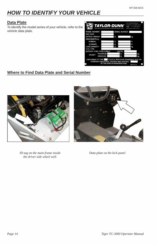
HOW TO IDENTIFY YOUR VEHICLEData PlateTo identify the model series of your vehicle, refer to the vehicle data plate.
Where to Find Data Plate and Serial Number
Data plate on the kick panel ID tag on the main frame inside the driver side wheel well.
Page 15Tiger TC-3060 Operator Manual
MT-030-60-E
HOW TO IDENTIFY YOUR ENGINE & TRANSMISSION
Page 16 Tiger TC-3060 Operator Manual
MT-030-60-E
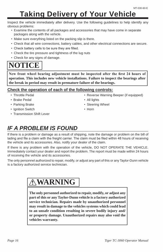
Taking Delivery of Your VehicleInspect the vehicle immediately after delivery. Use the following guidelines to help identify any obvious problems:
• Examine the contents of all packages and accessories that may have come in separate packages along with the vehicle.
• Make sure everything listed on the packing slip is there.• Check that all wire connections, battery cables, and other electrical connections are secure.• Check battery cells to be sure they are filled.• Check the tire pressure and tightness of the lug nuts• Check for any signs of damage.
Check the operation of each of the following controls:
IF A PROBLEM IS FOUNDIf there is a problem or damage as a result of shipping, note the damage or problem on the bill of lading and file a claim with the freight carrier. The claim must be filed within 48 hours of receiving the vehicle and its accessories. Also, notify your dealer of the claim.If there is any problem with the operation of the vehicle, DO NOT OPERATE THE VEHICLE. Immediately contact your dealer and report the problem. The report must be made within 24 hours of receiving the vehicle and its accessories.The only personnel authorized to repair, modify, or adjust any part of this or any Taylor-Dunn vehicle is a factory authorized service technician.
• Throttle Pedal• Brake Pedal• Parking Brake• Ignition Switch• Transmission Shift Lever
• Reverse Warning Beeper (if equipped)• All lights• Steering Wheel• Horn
The only personnel authorized to repair, modify, or adjust any part of this or any Taylor-Dunn vehicle is a factory authorized service technician. Repairs made by unauthorized personnel may result in damage to the vehicles systems which could lead to an unsafe condition resulting in severe bodily injury and/or property damage. Unauthorized repairs may also void the vehicles warranty.
WARNING
NOTICENew front wheel bearing adjustment must be inspected after the first 24 hours of operation. This includes new vehicle installations. Failure to inspect the bearings after the break in period may result in premature failure of the bearings.

Page 17Tiger TC-3060 Operator Manual
MT-030-60-E
Operator TrainingPer the following regulations, the owner of this vehicle shall conduct an Operator Training program for all those who will be operating this vehicle:
• ANSI/ITSDF 56.8-2006 Personnel and Burden Carriers: Part II, Paragraph 6.2a.• ANSI/ITSDF 56.9 – 2007 Safety Standard for Operator Controlled Industrial Tow Tractors:
Part II, paragraph 4.11.• Code of Federal Regulations (CFR) Title 29, Subtitle B, Chapter Xvii OSHA, Part 1910.178
Powered Industrial Trucks (2011): 1910.178, Section (l).• Per OSHA Regulation, 29 CFR 1910.178 Powered Industrial Truck Operator Training, the
owner must keep a record of conducted training and maintenance performed on the vehicle.The training program shall not be condensed for those claiming to have previous vehicle operation experience. Successful completion of the Operator Training program shall be required for all personnel who operate this vehicle. The Operator Training program shall include the following:
• Operation of this vehicle under circumstances normally associated with your particular environment.
• Emphasis on the safety of cargo and personnel.• All safety rules contained within this manual.• Proper operation of all vehicle controls.• A vehicle operation and driving test.
Driver QualificationsOnly those who have successfully completed the Operator Training program are authorized to drive this vehicle. Operators must possess the visual, auditory, physical, and mental ability to safely operate this vehicle as specified in the American National Standards Institute Controlled Personnel and Burden Carriers ANSI B56.8 and/or American National Standards Institute Controlled Industrial Tow Tractors B56.9.The following are minimum requirements necessary to qualify as an operator of this vehicle:• Demonstrate a working knowledge of each control.• Understand all safety rules and guidelines as presented in this manual.• Know how to properly load and unload cargo.• Know how to properly park this vehicle.• Recognize an improperly maintained vehicle.• Demonstrate the ability to handle this vehicle in all conditions.
www.taylor-dunn.com
Page 18 Tiger TC-3060 Operator Manual
MT-030-60-E
Page 19Tiger TC-3060 Operator Manual
MT-030-60-E
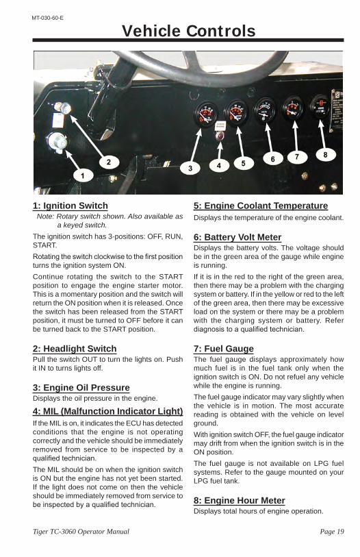
Vehicle Controls
1: Ignition SwitchNote: Rotary switch shown. Also available as
a keyed switch.The ignition switch has 3-positions: OFF, RUN, START.Rotating the switch clockwise to the first position turns the ignition system ON.Continue rotating the switch to the START position to engage the engine starter motor. This is a momentary position and the switch will return the ON position when it is released. Once the switch has been released from the START position, it must be turned to OFF before it can be turned back to the START position.
2: Headlight SwitchPull the switch OUT to turn the lights on. Push it IN to turns lights off.
3: Engine Oil PressureDisplays the oil pressure in the engine.
4: MIL (Malfunction Indicator Light)If the MIL is on, it indicates the ECU has detected conditions that the engine is not operating correctly and the vehicle should be immediately removed from service to be inspected by a qualified technician.The MIL should be on when the ignition switch is ON but the engine has not yet been started. If the light does not come on then the vehicle should be immediately removed from service to be inspected by a qualified technician.
5: Engine Coolant TemperatureDisplays the temperature of the engine coolant.
6: Battery Volt MeterDisplays the battery volts. The voltage should be in the green area of the gauge while engine is running.If it is in the red to the right of the green area, then there may be a problem with the charging system or battery. If in the yellow or red to the left of the green area, then there may be excessive load on the system or there may be a problem with the charging system or battery. Refer diagnosis to a qualified technician.
7: Fuel GaugeThe fuel gauge displays approximately how much fuel is in the fuel tank only when the ignition switch is ON. Do not refuel any vehicle while the engine is running.The fuel gauge indicator may vary slightly when the vehicle is in motion. The most accurate reading is obtained with the vehicle on level ground.With ignition switch OFF, the fuel gauge indicator may drift from when the ignition switch is in the ON position.The fuel gauge is not available on LPG fuel systems. Refer to the gauge mounted on your LPG fuel tank.
8: Engine Hour MeterDisplays total hours of engine operation.
Page 20 Tiger TC-3060 Operator Manual
MT-030-60-E
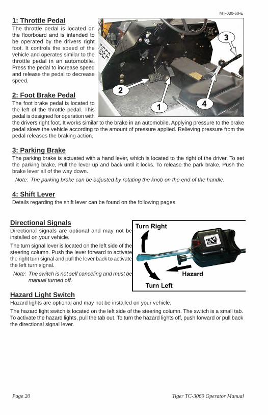
1: Throttle PedalThe throttle pedal is located on the floorboard and is intended to be operated by the drivers right foot. It controls the speed of the vehicle and operates similar to the throttle pedal in an automobile. Press the pedal to increase speed and release the pedal to decrease speed.
2: Foot Brake PedalThe foot brake pedal is located to the left of the throttle pedal. This pedal is designed for operation with the drivers right foot. It works similar to the brake in an automobile. Applying pressure to the brake pedal slows the vehicle according to the amount of pressure applied. Relieving pressure from the pedal releases the braking action.
3: Parking BrakeThe parking brake is actuated with a hand lever, which is located to the right of the driver. To set the parking brake, Pull the lever up and back until it locks. To release the park brake, Push the brake lever all of the way down.
Note: The parking brake can be adjusted by rotating the knob on the end of the handle.
4: Shift LeverDetails regarding the shift lever can be found on the following pages.
Directional SignalsDirectional signals are optional and may not be installed on your vehicle.The turn signal lever is located on the left side of the steering column. Push the lever forward to activate the right turn signal and pull the lever back to activate the left turn signal.
Note: The switch is not self canceling and must be manual turned off.
Hazard Light SwitchHazard lights are optional and may not be installed on your vehicle.The hazard light switch is located on the left side of the steering column. The switch is a small tab. To activate the hazard lights, pull the tab out. To turn the hazard lights off, push forward or pull back the directional signal lever.
Page 21Tiger TC-3060 Operator Manual
MT-030-60-E
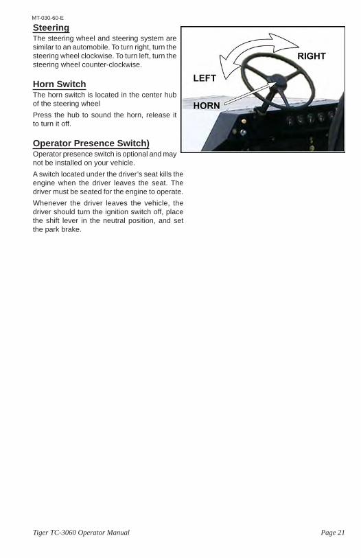
Steering The steering wheel and steering system are similar to an automobile. To turn right, turn the steering wheel clockwise. To turn left, turn the steering wheel counter-clockwise.
Horn SwitchThe horn switch is located in the center hub of the steering wheelPress the hub to sound the horn, release it to turn it off.
Operator Presence Switch)Operator presence switch is optional and may not be installed on your vehicle.A switch located under the driver’s seat kills the engine when the driver leaves the seat. The driver must be seated for the engine to operate.Whenever the driver leaves the vehicle, the driver should turn the ignition switch off, place the shift lever in the neutral position, and set the park brake.
Page 22 Tiger TC-3060 Operator Manual
MT-030-60-E
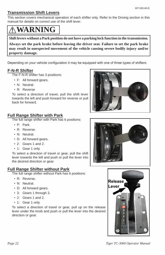
Transmission Shift LeversThis section covers mechanical operation of each shifter only. Refer to the Driving section in this manual for details on correct use of the shift lever.
Depending on your vehicle configuration it may be equipped with one of three types of shifters:
F-N-R ShifterThe F-N-R shifter has 3 positions:
• F: All forward gears.• N: Neutral.• R: Reverse
To select a direction of travel, pull the shift lever towards the left and push forward for reverse or pull back for forward.
Full Range Shifter with ParkThe full range shifter with Park has 6 positions:
• P: Park.• R: Reverse.• N: Neutral.• D: All forward gears.• 2: Gears 1 and 2.• 1: Gear 1 only.
To select a direction of travel or gear, pull the shift lever towards the left and push or pull the lever into the desired direction or gear.
Full Range Shifter without ParkThe full range shifter without Park has 6 positions:
• R: Reverse.• N: Neutral.• D: All forward gears.• 3: Gears 1 through 3.• 2: Gears 1 and 2.• 1: Gear 1 only.
To select a direction of travel or gear, pull up on the release lever under the knob and push or pull the lever into the desired direction or gear.
Shift levers without a Park position do not have a parking lock function in the transmission.Always set the park brake before leaving the driver seat. Failure to set the park brake may result in unexpected movement of the vehicle causing severe bodily injury and/or property damage.
WARNING
Page 23Tiger TC-3060 Operator Manual
MT-030-60-E
Vehicle OperationGeneral Safety Guidelines
• Only qualified and trained operators with no physical, mental, or sensory disabilities shall operate this vehicle or any of its components.
• Before operating this vehicle, perform all Daily and Pre-operation checks as defined in the Vehicle Maintenance section.
• Confirm proper operation of all vehicle controls before operating the vehicle.• Wear closed toe low heel shoes when operating the vehicle.• No reckless driving.• Do not operate a motor vehicle while under the influence of alcohol or any drug that may
impair your ability to drive.• Keep all body parts (head, arms, legs) inside this vehicle while it is moving.• All occupants shall remain seated while the vehicle is in motion, one passenger per seating
position. No passengers are allowed to be transported in the cargo area of the vehicle.• The operator shall confirm that all passengers are physically able to secure themselves
while being transported in this vehicle.• Occupants shall not exit the vehicle until the vehicle has come to a complete stop.• Do not transport small children. This vehicle is not designed to accommodate child seats.• Do not leave children unattended in the vehicle.• Keep a clear view ahead at all times. • Keep the vehicle under control at all times. • Observe all traffic regulations and speed limits.• The vehicle shall be equipped with head and tail lights if operated at night.• This vehicle may overturn if turned sharply when driven at high speeds. • Drive slowly when making a turn, especially if the ground is wet or when driving on an
incline.• Yield right of way to pedestrians, ambulances, fire trucks, or other emergency vehicles.• Sound your horn when approaching pedestrians. DO NOT assume the pedestrian is aware
of your presence; before passing, slow down and allow sufficient clearance between the vehicle and pedestrian.
Your ability to operate a motor vehicle can be seriously impaired with blood alcohol levels far below the legal minimum.If you have been drinking alcohol, don’t drive. Ride with a designated non-drinking driver, call a cab, or use public transportation.
WARNING
When leaving the approved operating position ALWAYS:1) Firmly set the park brake.2) Place the shift level in the Park or Neutral position.3) Turn the start switch OFF and remove the key.Failure to perform these operations may result in unexpected vehicle movement causing severe bodily injury and/or property damage.
WARNING
Page 24 Tiger TC-3060 Operator Manual
MT-030-60-E
• Do not overtake another vehicle at intersections, blind spots, narrow isles, or other dangerous locations.
• Stop and sound horn at all intersections regardless if it is posted with a stop sign.• Do not operate this vehicle in areas at risk to falling objects.• Do not drive over loose objects, holes, or bumps.• Do not drive under any object that is less than 85 inches (216 cm) from the ground.• Do not drive off of curbs or other steep drop-offs more than 2 inches high.• Stay in your driving lane under normal conditions, maintaining a safe following distance from
other vehicles.• If equipped with doors, the doors must remain closed and latched while vehicle is in motion.• Driving through water or mud may affect brake performance. ALWAYS test brakes by
pressing the brake pedal after driving through water or mud.
Page 25Tiger TC-3060 Operator Manual
MT-030-60-E
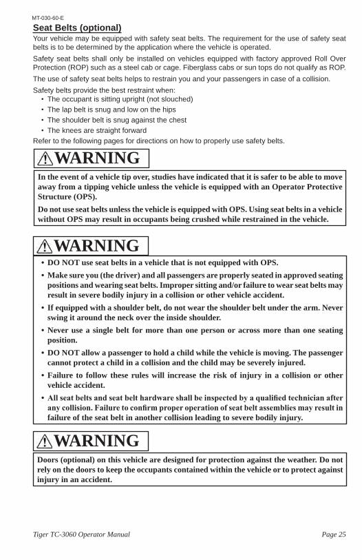
Seat Belts (optional)Your vehicle may be equipped with safety seat belts. The requirement for the use of safety seat belts is to be determined by the application where the vehicle is operated.Safety seat belts shall only be installed on vehicles equipped with factory approved Roll Over Protection (ROP) such as a steel cab or cage. Fiberglass cabs or sun tops do not qualify as ROP.The use of safety seat belts helps to restrain you and your passengers in case of a collision.Safety belts provide the best restraint when:
• The occupant is sitting upright (not slouched)• The lap belt is snug and low on the hips• The shoulder belt is snug against the chest• The knees are straight forward
Refer to the following pages for directions on how to properly use safety belts.
In the event of a vehicle tip over, studies have indicated that it is safer to be able to move away from a tipping vehicle unless the vehicle is equipped with an Operator Protective Structure (OPS).Do not use seat belts unless the vehicle is equipped with OPS. Using seat belts in a vehicle without OPS may result in occupants being crushed while restrained in the vehicle.
WARNING
• DO NOT use seat belts in a vehicle that is not equipped with OPS.• Make sure you (the driver) and all passengers are properly seated in approved seating
positions and wearing seat belts. Improper sitting and/or failure to wear seat belts may result in severe bodily injury in a collision or other vehicle accident.
• If equipped with a shoulder belt, do not wear the shoulder belt under the arm. Never swing it around the neck over the inside shoulder.
• Never use a single belt for more than one person or across more than one seating position.
• DO NOT allow a passenger to hold a child while the vehicle is moving. The passenger cannot protect a child in a collision and the child may be severely injured.
• Failure to follow these rules will increase the risk of injury in a collision or other vehicle accident.
• All seat belts and seat belt hardware shall be inspected by a qualified technician after any collision. Failure to confirm proper operation of seat belt assemblies may result in failure of the seat belt in another collision leading to severe bodily injury.
WARNING
Doors (optional) on this vehicle are designed for protection against the weather. Do not rely on the doors to keep the occupants contained within the vehicle or to protect against injury in an accident.
WARNING
Page 26 Tiger TC-3060 Operator Manual
MT-030-60-E
All Seat Belt TypesRefer to additional details below for details applying to different types of seat belts.Before fastening the seat belt:
• If equipped with adjustable seats, adjust the seat to the position that suits you best.• Make sure the shoulder and/or lap belt is not twisted and freely passes through any guides.
To unfasten the belt, Push the release button on in the buckle.
Combination Lap and Shoulder BeltsWhile your vehicle is in motion, the combination lap and shoulder belt adjusts to your movement. However, if you brake hard, corner hard or if your vehicle receives an impact of 5 mph (8 kph) or more, the lap and shoulder belt locks and helps reduce your forward movement. The retractor can also be made to lock by rapidly pulling on the belt.To fasten the belt, pull the lap/shoulder belt from the retractor so that the shoulder portion of the belt crosses your shoulder and chest. Insert the belt tongue into the proper buckle until you hear a snap and feel it latch. To unfasten the belt, Push the release button on in the buckle. This allows the tongue to unlatch from the buckle. Guide the tongue to its stowed position while the belt retracts. If you do not guide the tongue, it may strike you or part of the vehicle.
Lap Belts OnlyWith Auto Retractor: To fasten the belt, pull the belt from the retractor and insert the belt tongue into the proper buckle until you hear a snap and feel it latch. Make sure the tongue is securely fastened in the buckle.When unfastening the belt, guide the belt tongue to its stowed position. If you do not guide the tongue, it may strike you or part of the vehicle.Without Auto Retractor: To fasten the belt, insert the belt tongue into the proper buckle until you hear a snap and feel it latch. Pull the belt adjustor strap until the belt is snug against your lap.After unfastening the belt, stow the belt in a position so that it cannot fall out of the vehicle while the vehicle is in motion and the belt is not in use.
Seat Belts While PregnantIf equipped with seat belts, always wear a seat belt. Wearing your seat belt protects you and your baby from injury or death in the event of a collision.Be sure to wear your seat belt correctly. The lap strap shall go under your belly, across your hips and as high as possible on your thighs. The shoulder strap shall go between your breasts and off to the side of your belly. Seat belt straps shall never go directly across your stomach. The seat belt should fit snugly.
Seat Belt MaintenanceCheck the safety seat belt systems periodically to make sure that they work properly and are not damaged.All safety seat belt assemblies, including retractors, buckles, front seat belt buckle support assemblies and attaching hardware, shall be inspected by a qualified technician after any collision. Taylor-Dunn recommends that all safety seat belt assemblies used in vehicles involved in a collision be replaced. However, if the collision was minor and a qualified technician finds that the belts do not show damage and continue to operate properly, they do not need to be replaced. Safety belt assemblies not in use during a collision shall also be inspected and replaced if either damage or improper operation is noted.
Page 27Tiger TC-3060 Operator Manual
MT-030-60-E
Starting the Engine
Before operating this vehicle: Refer to General Safety Guidelines at the beginning of this chapter.Perform all necessary vehicle preparation steps, inspections, or maintenance before operating this vehicle.
Note: The vehicle may be equipped with a various start interlock switches. All interlock switches must be closed to allow the engine to start.
All Engines:1. Place the transmission shift lever in Park or Neutral.2. Set the parking brake.3. Press the foot brake pedal.
Gasoline:4. Rotate the ignition switch to the START position and
hold (see Cautions above) until the engine starts and then release the switch.
Diesel:4. Rotate the ignition switch to the ON position and wait for the WAIT to START lamp to go out,
then Rotate the ignition switch to the START position and hold (see Cautions above) until the engine starts and then release the switch.
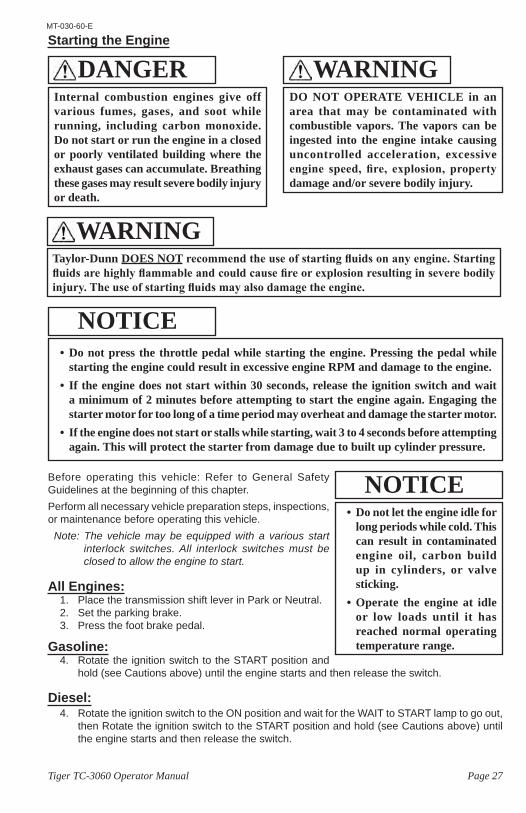
Internal combustion engines give off various fumes, gases, and soot while running, including carbon monoxide. Do not start or run the engine in a closed or poorly ventilated building where the exhaust gases can accumulate. Breathing these gases may result severe bodily injury or death.
DANGERDO NOT OPERATE VEHICLE in an area that may be contaminated with combustible vapors. The vapors can be ingested into the engine intake causing uncontrolled acceleration, excessive engine speed, fire, explosion, property damage and/or severe bodily injury.
WARNING
• Do not press the throttle pedal while starting the engine. Pressing the pedal while starting the engine could result in excessive engine RPM and damage to the engine.
• If the engine does not start within 30 seconds, release the ignition switch and wait a minimum of 2 minutes before attempting to start the engine again. Engaging the starter motor for too long of a time period may overheat and damage the starter motor.
• If the engine does not start or stalls while starting, wait 3 to 4 seconds before attempting again. This will protect the starter from damage due to built up cylinder pressure.
NOTICE
Taylor-Dunn DOES NOT recommend the use of starting fluids on any engine. Starting fluids are highly flammable and could cause fire or explosion resulting in severe bodily injury. The use of starting fluids may also damage the engine.
WARNING
• Do not let the engine idle for long periods while cold. This can result in contaminated engine oil, carbon build up in cylinders, or valve sticking.
• Operate the engine at idle or low loads until it has reached normal operating temperature range.
NOTICE
Page 28 Tiger TC-3060 Operator Manual
MT-030-60-E
If operated for extended time at, or close to full load, allow the engine to idle for 3 to 5 minutes before stopping the engine to allow internal engine temperatures to stabilize.
NOTICE
LPG:Ford LPG engines may be equipped with an automated start and shut down system called Auto Crank. The Auto Crank feature controls starting and stopping the engine to minimize the possibility of engine intake backfire. For engines without the Auto Crank feature; Follow instructions for gasoline engine.4. Rotate the ignition switch to the START and release.
• The engine will crank for a pre programmed time period.• Repeat 1 or 2 times• If the engine does not start refer repair to a qualified technician.
Stopping the Engine
Follow instructions for parking the vehicle before turning the engine OFF.
Gasoline/Diesel:Turn the ignition switch OFF.
LPG:Ford LPG engines may be equipped with an automated start and shut down system called Auto Crank. The Auto Crank feature controls starting and stopping the engine to minimize the possibility of engine intake backfire. For engines without the Auto Crank feature; Follow instructions for gasoline engine.The engine will continue to run for up to 5 seconds after turning the ignition switch OFF. DO NOT leave the approved operator position until the engine has stopped.
RefuelingRefer to the engine operation manual for details regarding approved fuel types.The following guidelines should be followed regardless of fuel type:
• Turn the engine off before refueling.• No smoking or open flames.• Only refuel in an area approved for
refueling with adequate ventilation.• If using LPG, turn the LPG tank valve
off before disconnecting the fuel line.
The fuel system may be under pressure. If the fuel cap or LPG fuel hose is venting vapor or if you hear a hissing sound while removing the fuel cap or disconnecting the LPG tank hose, wait until the hissing stops before completely removing the cap or line.Failure to follow this procedure may result in fuel spraying out of the system and causing bodily injury.
WARNING
Page 29Tiger TC-3060 Operator Manual
MT-030-60-E
• Read the battery warning in the Battery maintenance section of this manual before attempting to jump start a vehicle.
• Confirm that the jump start vehicle has the same voltage ground type electrical system as the dead vehicle. Incompatible systems will result in damage to one or both vehicle electrical systems.
• Incorrect connection of jumper cables will result in damage to one or both vehicle electrical systems.
• Make sure that the jumper cable clamps are securely connected. Loose connections may result in electrical arcing, damage to the battery and/or severe bodily injury.
• The engine on the vehicle being used to jump start shall be OFF while connecting cables.
WARNINGJump Starting
1. Park the jump start vehicle close to the dead vehicle and turn the engine OFF.2. Connect the red (+) cable clamp to the battery positive terminal on the dead vehicle. Make
sure the black cable clamp is insulated from the vehicle.3. Connect the other end of the red (+) cable clamp to the battery positive terminal on the
vehicle that is used to jump start.4. Connect the black (-) cable clamp to the battery negative terminal on the vehicle that is
used to jump start.5. BEFORE NEXT STEP, CONFIRM CABLES ARE FIRMLY CONNECTED TO THE CORRECT
BATTERY TERMINALS.6. Connect the black (-) cable to the engine block on the dead vehicle.7. Start the engine of the jump start vehicle and bring to high idle RPM.8. Attempt to start the dead vehicle following normal starting procedures.9. After completing the jump start, disconnect the cables from the vehicles in this order:
• Engine block, jumped vehicle.• Battery negative, other vehicle. • Battery positive, jumped vehicle.• Battery positive, other vehicle.
10. Do not turn the engine off until the battery has had time to charge.
• DO NOT allow the two unconnected cable clamps to touch each other. This will cause a short circuit and may damage the vehicle electrical system and/or result in bodily injury.
• DO NOT allow the two vehicles to touch each other. This may cause a short circuit and may damage the vehicle electrical system and/or result in bodily injury.
• Make sure that the cables are routed away from any moving components such as fans and drive belts.
• Make sure that the cables are secured in place and cannot move into any moving components such as fans and drive belts.
CAUTION
Frequently required jump starts is an indication of a faulty battery or charging system. Refer diagnosis to a qualified technician.
NOTICE
Page 30 Tiger TC-3060 Operator Manual
MT-030-60-E
DrivingBefore operating this vehicle:
• Perform all daily and pre-operation checks as defined in the Vehicle Maintenance section.• Refer to General Safety Guidelines at the beginning of this section.
Confirm engine is at low idle before selecting or changing direction. If the engine is not at low idle then the vehicle may lurch forward or back resulting in loss of control of the vehicle, severe bodily injury, property damage and/or damage to the transmission.
WARNING
DO NOT exceed the maximum rated speed for your vehicle, locally imposed speed limits, or the safe operating speed for conditions. Exceeding any of these speed limits will increase the likelihood of an accident causing bodily injury. In addition, exceeding the maximum rated speed for your vehicle may result in damage to the vehicle drive train.
WARNING
DO NOT “ride the brakes” or drive with your left foot resting on the brake pedal.Riding the brakes will cause excessive heat build up and rapid wear in the brake system and could result in brake failure causing a collision or accident with severe injury.
WARNING
Do not coast with the shift lever in the Neutral position. Engine braking is disabled in the Neutral position and could cause loss of control of the vehicle resulting in property damage and/or severe bodily injury.
WARNING
Firmly apply the foot brake before moving the shift lever into or out of the Park or Neutral positions. Moving the shift lever without the brake applied may cause unexpected vehicle movement resulting in property damage and/or severe bodily injury.
WARNING
• Always apply the parking brake when leaving the approved operator position. Selecting Neutral DOES NOT apply the vehicle brakes or any locking device to prevent vehicle movement. An unoccupied vehicle without the park brake applied may move unexpectedly resulting in property damage and/or severe bodily injury.
• DO NOT rely on the parking brake to prevent vehicle movement while the engine is running. Turn the engine OFF or block the wheels AND set the parking brake if you must leave the approved operator position with the engine running. Failure to follow these instructions may result in unexpected vehicle movement resulting in property damage and/or severe bodily injury.
WARNING
Do not idle with any gear selected for more than 5 minutes. Idling with a gear selected will cause the transmission temperature to rise. Extended idle times can result in transmission overheating.
NOTICE
Page 31Tiger TC-3060 Operator Manual
MT-030-60-E
1. Press the foot brake pedal.2. Release the parking brake.3. Start the engine. Refer to Starting the Engine for details regarding starting the engine.4. Move the transmission shift lever into the desired direction and/or range (see below).5. Slowly press the throttle pedal to increase speed.
Selecting Gear Range (typical)This section is for vehicles equipped with a full range shifter. Refer to Allison 2100 section for additional functions with this transmission.A full range shifter will have one reverse gear, 3 or 4 selectable forward gear ranges, and Overdrive on some transmissions. It will also have a Park and/or Neutral position. The actual type of shifter will vary depending on the vehicle configuration.The highest gear range will be represented by the highest available number or represented by the letter “D”.Use the highest range available for most driving conditions. The transmission will select the range most suitable for the current driving conditions.Selecting overdrive when driving longer distances with lighter loads will increase fuel economy.Use lower ranges to increase engine braking on downgrades. Each successive lower range will have more braking power than the higher range.
Allison 2100This section covers additional information regarding the Allison 2100 transmission shifting functions. Also refer to Selecting Gear Range section for additional information.The Allison 2100 is a computer controlled transmission with additional functions that control the shifting patterns.Shift Inhibit Lamp: The shift inhibit light will be located on the dash panel. If the shift inhibit light is ON then shifting of the transmission has been disabled due to a fault. Detail is provided in the following paragraph. The Shift Inhibit light should flash ON for 2 seconds when starting the engine. If the light does not come on then the vehicle should be immediately removed from service to have the transmission system inspected.Selecting a direction: Put the shift lever in neutral and apply the foot brake before selecting direction. If you select (or change) a direction without applying the foot brake then the dash Shift Inhibit light will be illuminated and the transmission will be locked in neutral. To reset you must put the shift lever back in neutral, apply the foot brake, then re-select the direction desired.Low gear ranges: When a low gear range is selected then shifting to higher gears is inhibited unless the engine governed speed is exceeded. If the engine governed speed is exceeded then the transmission will allow upshift to protect the engine. Use the foot brake to prevent the engine from exceeding its governed speed on downgrades when lower ranges are selected.
Reversing DirectionAlways come to a complete stop before moving the shift lever to Neutral, Park or other direction.
DO NOT transport or load cargo in the front passenger area or leave loose items on the front floorboard. Cargo placed in the front passenger area may interfere with the driver causing loss of control of the vehicle and result in a collision or accident with severe injury.
WARNING

Page 32 Tiger TC-3060 Operator Manual
MT-030-60-E
StoppingRelease the throttle pedal and use your right foot to press the brake pedal. The amount of force required to stop the vehicle will vary depending on the environment and load on the vehicle.
Parking1. Bring the vehicle to a stop at an authorized parking space. 2. Firmly set the parking brake.3. Place the shift lever in Park or Neutral if Park is not available.4. Turn the ignition switch OFF.
Note: If parking this vehicle on an incline, turn the wheels to the curb, or block the wheels.
Parking with Engine RunningIt is not recommended to leave the approved operator position while the engine running. Follow the following steps if you find it necessary to leave the engine running:1. Place the shift lever in Park or Neutral if Park is not available.2. Firmly set the parking brake.3. If Park is not available then block the wheels immediately after leaving the approved operator
position.
Emergency Engine Kill SwitchThe Emergency Engine Kill Switch is optional and may ne be installed on your vehicle.This vehicle may be equipped with an optional Emergency Engine Kill Switch. When activated, the Emergency Kill Switch will immediately stop the engine.The emergency engine kill Switch should be used if the vehicle starts to operate in an unexpected manner or if there is an odor or sound that may indicate an overloaded electrical circuit. If any of the above occurs, immediately and safely pull to the side of the road and stop. Then push on the switch knob, turn the ignition switch OFF and exit the vehicle. Do not reengage the switch until the vehicle has been inspected by a qualified technician.The emergency engine kill Switch should only be activated if the vehicle must be immediately stopped. Do not use the switch when only parking the vehicle.The location of the switch will vary depending on vehicle configuration. The switch is a large red knob located within reach of the driver. See the illustration to the left for a typical kill switch knob.
Collisions or AccidentsA collision or accident may damage the electrical circuits or battery resulting in a fire hazard or chemical spill. In the event of a collision or accident, immediately turn the ignition switch OFF, set the park brake, then exit the vehicle.Call emergency personnel if there is any indication of smoke, burning smell, electrical arcing, or leaking fluid.
Tip OverIn the event of a tip over AND the vehicle is equipped with an Operator Protective Structure (OPS), stay inside the confines of the vehicle. Exit the vehicle after the vehicle has come to a complete stop.In the event of a tip over and the vehicle IS NOT equipped with OPS. Quickly exit the vehicle and quickly move out of its path.
Unless in an emergency, do not activate the emergency engine kill Switch while the vehicle is in motion. This vehicle is equipped with power hydraulic steering and power hydraulic assist brakes. If turned off, the steering will be very heavy and braking force will be diminished required much more foot pedal pressure to apply the brakes. This will increase distance required to stop and may result in collision and severe bodily injury.
WARNING
Page 33Tiger TC-3060 Operator Manual
MT-030-60-E
Towing
Towing a TrailerNote: Towingupordowngradeswillsignificantlyreducethecapacityofthevehicle.
When towing trailers: • Do not exceed the DBP towing capacity of the vehicle. See Specifications and DBP
definition.• Only use Taylor-Dunn approved trailer hitches.• Do not exceed the capacity of the trailer hitch installed on the vehicle. • Do not exceed the load capacity of the trailer. Refer to documentation supplied with your
trailer for information regarding load capacity of the trailer.• Make sure all loads are securely tied down. Refer to documentation supplied with your
trailer for information regarding attaching loads to the trailer.• Cargo consisting of fluid in tanks shall have fluid baffles in the tank to help reduce shifting
load weight.• Do not back up when towing more than one trailer.• Drive slowly when towing loads with a high center of gravity.• When turning, be sure to allow for “corner cutting” of the trailer.• Allow for longer stopping distances when towing heavy loads.• Allow for longer stopping distances when driving down a grade.• Block the trailer wheels before disconnecting from the vehicle.• Do not disconnect a trailer while parked on a grade.
Draw Bar Pull (DBP), DefinitionDBP is a measure of pulling force required to move a load. The load may be a trailing load or a pushed load. It is normally expressed in pounds or Newtons.The DBP of a tow tractor is the horizontal force exerted on a load at its coupler while towing or pushing a load. To measure the DBP, a scale would be connected in line with the tractor coupler and the load. The scale will directly read the DBP as the tractor tows the load.Tow tractor DBP specifications, definition:
• Normal DBP: Highest DBP that can be sustained for a given duty cycle.• Ultimate DBP: Also referred to a Maximum DBP. Highest DBP achieved while traveling at
a minimum speed of approximately 0.5 mph (0.8 kph) for a minimum of 30 seconds. This specification is used in calculations for getting a load moving.
Notes: Tow tractor DBP specifications are based on:
• Road surface consisting of level dry clean asphalt, brushed concrete or equivalent.• Maximum battery weight installed per tow tractor battery specification.
Towing a load up any grade will significantly increase the DBP required.Most paved roads and parking lots have a drainage grade to allow water to run off. When operating a tow tractor at or near its maximum capacity, this drainage grade will significantly affect DBP required to pull the load and may result in exceeding the tractor specifications.
Use caution when towing trailers wider than the tow tractor allowing for additional isle clearance and corner cutting of the trailers.Not allowing for additional clearance may result in collision with severe bodily injury and/or property damage.
WARNING
Page 34 Tiger TC-3060 Operator Manual
MT-030-60-E
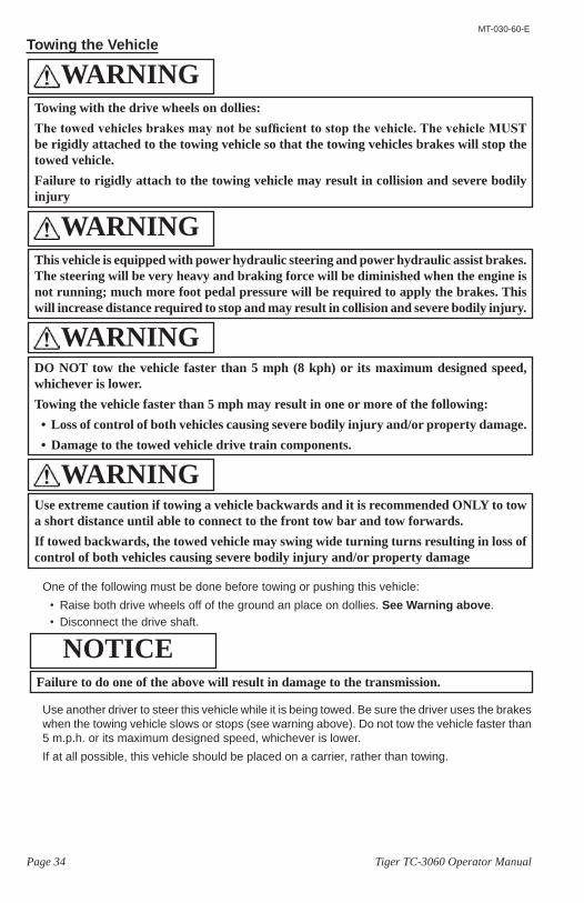
Towing the Vehicle
One of the following must be done before towing or pushing this vehicle:• Raise both drive wheels off of the ground an place on dollies. See Warning above.• Disconnect the drive shaft.
Use another driver to steer this vehicle while it is being towed. Be sure the driver uses the brakes when the towing vehicle slows or stops (see warning above). Do not tow the vehicle faster than 5 m.p.h. or its maximum designed speed, whichever is lower.If at all possible, this vehicle should be placed on a carrier, rather than towing.
This vehicle is equipped with power hydraulic steering and power hydraulic assist brakes. The steering will be very heavy and braking force will be diminished when the engine is not running; much more foot pedal pressure will be required to apply the brakes. This will increase distance required to stop and may result in collision and severe bodily injury.
WARNING
Failure to do one of the above will result in damage to the transmission.
NOTICE
Towing with the drive wheels on dollies:The towed vehicles brakes may not be sufficient to stop the vehicle. The vehicle MUST be rigidly attached to the towing vehicle so that the towing vehicles brakes will stop the towed vehicle. Failure to rigidly attach to the towing vehicle may result in collision and severe bodily injury
WARNING
DO NOT tow the vehicle faster than 5 mph (8 kph) or its maximum designed speed, whichever is lower.Towing the vehicle faster than 5 mph may result in one or more of the following:• Loss of control of both vehicles causing severe bodily injury and/or property damage. • Damage to the towed vehicle drive train components.
WARNING
Use extreme caution if towing a vehicle backwards and it is recommended ONLY to tow a short distance until able to connect to the front tow bar and tow forwards.If towed backwards, the towed vehicle may swing wide turning turns resulting in loss of control of both vehicles causing severe bodily injury and/or property damage
WARNING
Page 35Tiger TC-3060 Operator Manual
MT-030-60-E
Engine Fuel
• Fuel must be kept clean and free from water contamination. Contaminated fuel can cause internal engine damage.
• Use of alternate fuels may void engine warranty.
NOTICE
Improperly formulated gasohol blends may cause performance problems and/or damage to the engine or fuel system. May also void the engine warranty.• The use of fuels that do not meet the
following specifications may lead to engine damage and void the engine warranty.
• If your gasoline or LPG engine knocks heavily then it may be due to inferior fuel. Contact a qualified technician to inspect the fuel and engine operation.
NOTICEUse of special fuels for cold weather (arctic) may result in one or more of the following:• Low engine power• Difficult starting • White smoke• Deterioration of emissions and misfire
at certain operating conditions.DO NOT use arctic fuels in temperatures above 0ºC (32ºF).
NOTICE
Fuel is highly flammable. Use extreme care whenever refuelling your vehicle.• Turn the engine off. DO NOT refuel with the engine running.• DO NOT remove the fuel cap while the engine is running.• Always refuel outdoors or in a well ventilated area.• DO NOT overfill the fuel tank. Do not fill the tank neck.• Fill the fuel tank with proper fuel for your engine. Filling the fuel tank with improper
fuel may result in a fire and will damage the engine.• Do not smoke or allow open flames or sparks in or near the area where refueling is
performed or where fuel is stored.• Wipe up all spills immediately.• If fuel spills on your skin or clothing, immediately wash it off with soap and water
and change clothing.• DO NOT mix gasoline, alcohol, or gasohol with diesel fuel. Mixing fuels may result in
explosion causing severe bodily injury and/or property damage.• DO NOT fill portable fuel containers on the vehicle. Remove the container an place
on the ground to refuel.
WARNING
Use of low quality LPG fuels may result in heavy end deposits in the fuel system.
NOTICE
Page 36 Tiger TC-3060 Operator Manual
MT-030-60-E
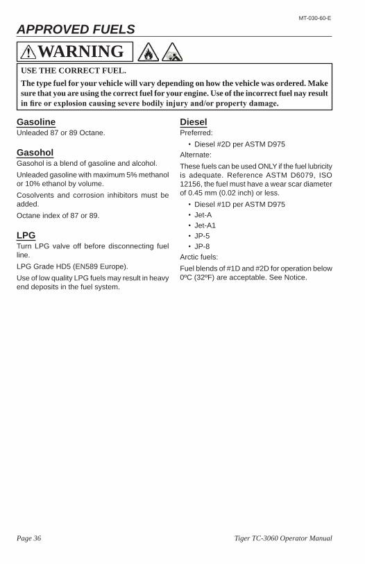
GasolineUnleaded 87 or 89 Octane.
GasoholGasohol is a blend of gasoline and alcohol.Unleaded gasoline with maximum 5% methanol or 10% ethanol by volume.Cosolvents and corrosion inhibitors must be added.Octane index of 87 or 89.
LPGTurn LPG valve off before disconnecting fuel line.LPG Grade HD5 (EN589 Europe).Use of low quality LPG fuels may result in heavy end deposits in the fuel system.
USE THE CORRECT FUEL.The type fuel for your vehicle will vary depending on how the vehicle was ordered. Make sure that you are using the correct fuel for your engine. Use of the incorrect fuel nay result in fire or explosion causing severe bodily injury and/or property damage.
WARNING
DieselPreferred:
• Diesel #2D per ASTM D975Alternate:These fuels can be used ONLY if the fuel lubricity is adequate. Reference ASTM D6079, ISO 12156, the fuel must have a wear scar diameter of 0.45 mm (0.02 inch) or less.
• Diesel #1D per ASTM D975• Jet-A• Jet-A1• JP-5• JP-8
Arctic fuels:Fuel blends of #1D and #2D for operation below 0ºC (32ºF) are acceptable. See Notice.
APPROVED FUELS
Page 37Tiger TC-3060 Operator Manual
MT-030-60-E
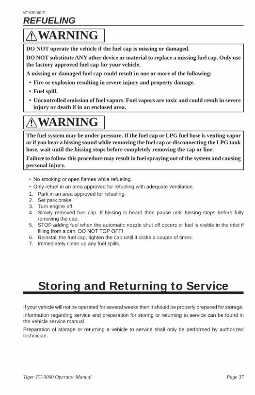
DO NOT operate the vehicle if the fuel cap is missing or damaged.DO NOT substitute ANY other device or material to replace a missing fuel cap. Only use the factory approved fuel cap for your vehicle.A missing or damaged fuel cap could result in one or more of the following:• Fire or explosion resulting in severe injury and property damage. • Fuel spill.• Uncontrolled emission of fuel vapors. Fuel vapors are toxic and could result in severe
injury or death if in an enclosed area.
WARNING
The fuel system may be under pressure. If the fuel cap or LPG fuel hose is venting vapor or if you hear a hissing sound while removing the fuel cap or disconnecting the LPG tank hose, wait until the hissing stops before completely removing the cap or line.Failure to follow this procedure may result in fuel spraying out of the system and causing personal injury.
WARNING
REFUELING
• No smoking or open flames while refueling.• Only refuel in an area approved for refueling with adequate ventilation.1. Park in an area approved for refueling.2. Set park brake.3. Turn engine off.4. Slowly removed fuel cap. If hissing is heard then pause until hissing stops before fully
removing the cap.5. STOP adding fuel when the automatic nozzle shut off occurs or fuel is visible in the inlet if
filling from a can. DO NOT TOP OFF!6. Reinstall the fuel cap; tighten the cap until it clicks a couple of times.7. Immediately clean up any fuel spills.
Storing and Returning to Service
If your vehicle will not be operated for several weeks then it should be properly prepared for storage.Information regarding service and preparation for storing or returning to service can be found in the vehicle service manual Preparation of storage or returning a vehicle to service shall only be performed by authorized technician.
Page 38 Tiger TC-3060 Operator Manual
MT-030-60-E
Vehicle MaintenanceDaily InspectionThe following items shall be inspected once every day before the vehicle is put into service:
• External frame damage (body).• Operation of all lights and warning alarms.• Proper operation of all instrument panel gauges and warning lights.• Smooth and proper operation of seat belts (if equipped).• Engine oil level.• Engine coolant level.• Fan belts.• Air cleaner service indicator (optional).• Drain fuel system water separator (diesel engines).• Transmission oil level.• Hydraulic system fluid level.• Brake fluid level.• Inspect for leaking fluids, grease, gasoline, or LPG fuel.• Tire tread or sidewall damage.• Proper operation of transmission shift lever and starter interlocks.• Proper operation of adjustable seat mechanisms (if equipped).• Smooth and proper operation of all controls such as but not limited to:
• Throttle pedal• Brake pedal• Parking brake• Steering• Horn• Etc.
• Proper operation of all locking mechanisms such as but not limited to:• Hood latches• Cargo box’s• Cab doors• Etc.
• Proper operation of all interlocking switches such as but not limited to:• Operator presence switch (optional)• Brake shift interlock (optional)• Shift lever interlock• Etc.
Pre-Operation InspectionThe following items shall be inspected every time before the vehicle is driven:
• Rear and side view mirror adjustments.• Steering operation.• Brake operation (service and park brake).• Tire pressure (visual inspection only).• Proper operation of trailer hitch.
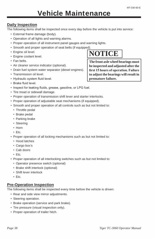
The front axle wheel bearings must be inspected and adjusted after the first 15 hours of operation. Failure to adjust the bearings will result in premature failure.
NOTICE
Page 39Tiger TC-3060 Operator Manual
MT-030-60-E
INTERLOCK SWITCH INSPECTIONThe interlock switches should disable vehicle operation when activated. Perform the following to confirm proper operation. If any one test fails, then immediately remove the vehicle from service and refer repair to a qualified technician.
Shift Lever InterlockThe shift lever interlock prevents engine starting unless the lever is in the Park or Neutral positions.
1. Firmly set the park brake.2. Hold firm pressure on the service brake pedal.3. Place the shift lever in all positions available and attempt to crank the engine.
• The engine should crank ONLY when in Neutral or Park.
Seat InterlockNote: The Seat Interlock is optional and may not be installed on your vehicle. Consult the original
vehicle sales order to determine if equipped with this option.The seat interlock prevents engine operation unless the driver is in the approved operator position.
1. Firmly set the park brake.2. Start the engine.3. Make sure transmission is in Park or Neutral.4. Get off of the driver seat.
• If equipped with this interlock, the engine should shut off within about 5 seconds.
Brake Shift InterlockNote: The Brake Shift Interlock is optional and may not be installed on your vehicle. If equipped
with this option, there will be a green shift light mounted in the operator area.The brake shift interlock should prevent shifting out of, or into gear unless the service brake pedal is firmly pressed.
1. Start the engine.2. Attempt to move the shift lever.
• The shift level should be locked in position.3. Firmly press the service brake pedal.
• The light should be ON and now able to move the shift lever.If only light brake pedal pressure is required, then the system is faulty or requires adjustment.
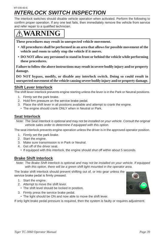
These procedures may result in unexpected vehicle movement. • All procedures shall be performed in an area that allows for possible movement of the
vehicle and room to safely stop the vehicle if it moves. • DO NOT allow any personnel to stand in front or behind the vehicle while performing
these procedures.Failure to follow the above instructions may result in severe bodily injury and/or property damage.DO NOT bypass, modify, or disable any interlock switch. Doing so could result in unexpected movement of the vehicle causing severe bodily injury and/or property damage.
WARNING
Page 40 Tiger TC-3060 Operator Manual
MT-030-60-E
Maintenance ScheduleMost of these items shall only be performed by a qualified technician. Refer to the vehicle, engine, or transmission service manual for details.Problems found during an inspection shall be repaired before the vehicle is put back into service.
First 15 hours• Re-torque wheel nuts.• Inspect all hardware for tightness.• Adjust front wheel bearings.
Every Week• All daily items plus the following:
• Check all tires tread for debris.
Every Month or 150 hours• All weekly items plus the following:
• Engine coolant level.• Change drive axle oil (first 150 hours only, then
2000 hours)• Clean radiator exterior.• Inspect/Adjust front wheel bearings.• Wash and clean battery and terminals• Check battery fluid level.• Check all tires air pressure.• Adjust valve lash, Cummins engine (first 150
hours then 2000 hours)• Change transmission filter (first 150 hours then
every 2000 hours).
Every 3 Months or 500 hours• All monthly items plus the following:
• Inspect/Adjust fan/accessory belts.• Inspect air filter, replace as required.• Inspect brake fluid level. • Inspect hydraulic fluid levels (power steering).• Inspect transmission fluid level.• Lubricate chassis.• Change engine oil.• Change fuel filters (KEM GM engine).• Adjust service and park brake. • Inspect wheel bearings• Re-torque the wheel nuts.• Inspect and tighten all power electrical
connections.• Inspect all hardware for tightness (first 500 hours
then every 1,000 hours).
Every 6 Months or 1,000 hours• All 3 month items plus the following:
• Inspect all hardware for tightness • Tighten all electrical connections.• Inspect wiring for cracks, fraying, wear.• Inspect engine cooling and/or heater hoses.• Inspect steering king pins. • Align the front end.
Every Year or 2,000 hours• All 6 month items plus the following:
• Inspect spark plugs.• Inspect valve lash (Perkins/Cummins engines)• Change hydraulic fluid and optional filter (power
steering).• Change fuel filters.• Change transmission fluid and filters• Change drive axle oil.• Clean and repack front wheel bearings, change
seals.• Test radiator cap.• Flush and replace the brake fluid.• Inspect service brakes for wear.• Test battery and alternator.• Inspect all suspension bushings.• Inspect the chassis for damage.• Rotate tires.
Every 2 Years or 4,000 hours• All yearly items plus the following:
• Change engine coolant.• Inspect/test fuel injectors.• Replace spark plugs and cables..• Inspect/clean PCV valve.• Replace fan/accessory belts.• Inspect water pump for leaks.• Inspect turbocharger.• Inspect engine mounts• Inspect parking brake for wear.
Every 4 Years or as Indicated by Transmission Service Lamp
• Change transmission fluid and filters (2100RDS Transmission)
Maintenance Guidelines for Severe Duty ApplicationsThe above maintenance schedule is based on the average typical application. If the vehicle is operated under “severe conditions”, service procedures shall be conducted more frequently than specified. The frequency of service under severe conditions is determined by the use of the vehicle. The owner/operator must evaluate the operating environment to determine the increase in maintenance frequency.In addition, the entire vehicle shall be inspected monthly for signs of damage.The following list is meant as a guide and is not all-inclusive of a “severe duty” application.
• Operation in excess of 150 hours per month.• Extreme temperature. • Bumpy, dusty, or ill maintained roads.• Excessively wet areas. • Corrosive or contaminated areas.• Frequent loading of the vehicle at or near capacity.
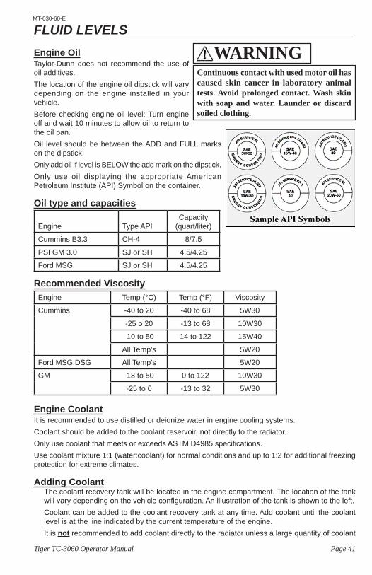
Page 41Tiger TC-3060 Operator Manual
MT-030-60-E
FLUID LEVELSEngine OilTaylor-Dunn does not recommend the use of oil additives.The location of the engine oil dipstick will vary depending on the engine installed in your vehicle.Before checking engine oil level: Turn engine off and wait 10 minutes to allow oil to return to the oil pan.Oil level should be between the ADD and FULL marks on the dipstick. Only add oil if level is BELOW the add mark on the dipstick.Only use oil displaying the appropriate American Petroleum Institute (API) Symbol on the container.
Oil type and capacities
Engine Type APICapacity
(quart/liter)
Cummins B3.3 CH-4 8/7.5
PSI GM 3.0 SJ or SH 4.5/4.25
Ford MSG SJ or SH 4.5/4.25
Recommended ViscosityEngine Temp (°C) Temp (°F) Viscosity
Cummins -40 to 20 -40 to 68 5W30
-25 o 20 -13 to 68 10W30
-10 to 50 14 to 122 15W40
All Temp’s 5W20
Ford MSG.DSG All Temp’s 5W20
GM -18 to 50 0 to 122 10W30
-25 to 0 -13 to 32 5W30
Engine CoolantIt is recommended to use distilled or deionize water in engine cooling systems.Coolant should be added to the coolant reservoir, not directly to the radiator.Only use coolant that meets or exceeds ASTM D4985 specifications.Use coolant mixture 1:1 (water:coolant) for normal conditions and up to 1:2 for additional freezing protection for extreme climates.
Adding CoolantThe coolant recovery tank will be located in the engine compartment. The location of the tank will vary depending on the vehicle configuration. An illustration of the tank is shown to the left.Coolant can be added to the coolant recovery tank at any time. Add coolant until the coolant level is at the line indicated by the current temperature of the engine.It is not recommended to add coolant directly to the radiator unless a large quantity of coolant
Continuous contact with used motor oil has caused skin cancer in laboratory animal tests. Avoid prolonged contact. Wash skin with soap and water. Launder or discard soiled clothing.
WARNING
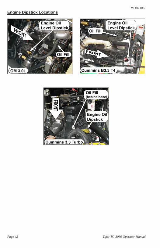
Page 42 Tiger TC-3060 Operator Manual
MT-030-60-E
Engine Dipstick Locations
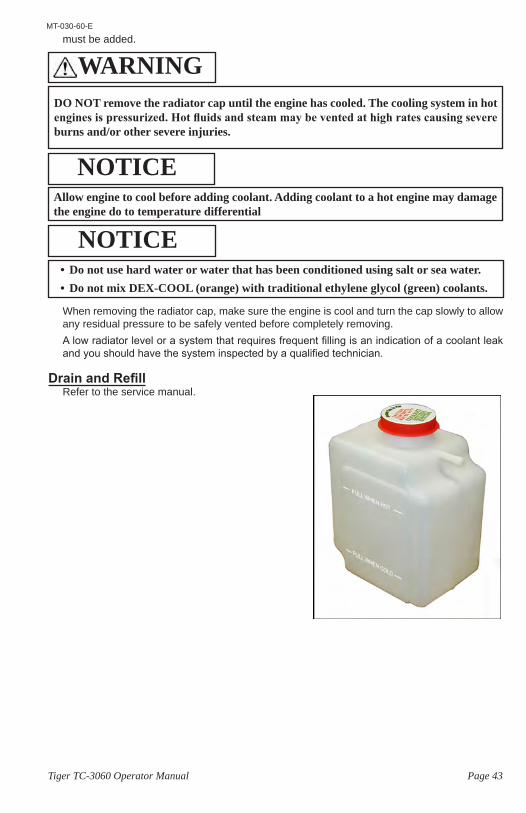
Page 43Tiger TC-3060 Operator Manual
MT-030-60-E
must be added.
When removing the radiator cap, make sure the engine is cool and turn the cap slowly to allow any residual pressure to be safely vented before completely removing.A low radiator level or a system that requires frequent filling is an indication of a coolant leak and you should have the system inspected by a qualified technician.
Drain and RefillRefer to the service manual.
DO NOT remove the radiator cap until the engine has cooled. The cooling system in hot engines is pressurized. Hot fluids and steam may be vented at high rates causing severe burns and/or other severe injuries.
WARNING
Allow engine to cool before adding coolant. Adding coolant to a hot engine may damage the engine do to temperature differential
NOTICE
• Do not use hard water or water that has been conditioned using salt or sea water.• Do not mix DEX-COOL (orange) with traditional ethylene glycol (green) coolants.
NOTICE

Page 44 Tiger TC-3060 Operator Manual
MT-030-60-E
Coolant SpecificationsCoolant specifications: 1:1 mix of water with coolant that meets ASTM D4985 specifications.Be sure to use good quality water Excessive levels of Calcium/Magnesium, chloride, or sulfur can lead to scaling problems or cooling system corrosion.
Water Quality
Elements Maximum Level
Calcium/Magnesium carbonates(CaCO3 + MgCO3) 170 ppm
Chloride (Cl) 40 ppm
Sulfur (SO4) 100 ppm
Total solids 340 mg.L
Acidity pH of 5.5 to 9.0
It is not necessary to remove the radiator cap to inspect the coolant level or add coolant to the system. Coolant level can be inspected at the coolant recovery tank.There are two level lines on the coolant recovery tank. The coolant level should be at the upper line when the engine is hot or the level should be at the lower line when the engine is cool.
Engine coolant system is pressurized. Allow the engine to cool before removing the radiator cap. Removing the radiator cap while the engine is hot may result in scalding hot fluid to be sprayed from the radiator causing severe bodily injury.
WARNING
Antifreeze (coolant) contains mono ethylene glycol and other constituents which are toxic if taken internally and can be absorbed in toxic amounts on repeated or prolonged skin contact. Persons using antifreeze are recommended to adhere to the following precautions:• Antifreeze must never be taken internally. If antifreeze is swallowed accidentally,
medical advice should be sought immediately.• Precautions should be taken to avoid skin contact with antifreeze. In the event of
accidental spillage onto the skin, antifreeze should be washed off as soon as practical. If clothing is splashed with antifreeze, it should be removed and washed before being worn again, to avoid prolonged skin contact.
• For regular and frequent handling of antifreeze, protective clothing (plastic or rubber gloves, boots and impervious overalls or aprons) must be used to minimize skin contact.
WARNING
Page 45Tiger TC-3060 Operator Manual
MT-030-60-E
Transmission FluidThe transmission fluid type may vary depending on the transmission installed in your vehicle. The transmission fluid should be changed if there is any discoloration or a strong odor.
5. Thoroughly clean area around the transmission dip stick before removing.
Cold CheckThe cold check is performed to be certain that there is enough fluid in the transmission for it to operate without damage.6. Run the engine at 1000-1500 RPM for
1-minute to purge air from the system.7. Firmly apply the service brake and shift
through all available gears.8. Shift to Park or Neutral and allow to idle.9. Remove the dipstick, wipe clean and
reinsert into the tube.10. Remove again check fluid level.
• If the fluid IS NOT within the “Cold Check” band, then drain or add fluid as needed to bring it into range.
• Once the fluid is within the “Cold Check” band then proceed to the Hot Check procedure.
Hot Check11. Operate the transmission in “D” or “F” until the sump temperature is between 160º - 200ºF
(71º-93ºC).Note: If transmission temperature gauge is not available, operate until engine is at normal operating
temperature and operate the transmission under load for 1-hour.12. Park the vehicle per warnings listed at the beginning of the procedure.13. Remove the dipstick, wipe clean and reinsert into the tube.14. Remove again check fluid level.
• If the fluid is not within the “Hot Run” band then drain or add fluid as required.
Transmission Fluid Specifications:Ford C6
Meets or exceeds Ford specification ESW-M2C33-F
Allison AT545 and 1000Dextron® III (below -13ºF [-25ºC] require preheat before operation)Allison Approved TES 295® (below -22ºF [-30ºC] requires preheat before operation)
Transmission fluid rises with temperature. Do not fill beyond the “Cold Check” band on the dipstick when the transmission is below normal operating temperature.An overfilled transmission may overheat and/or leak fluid leading to transmission damage.
NOTICE
1) Park the vehicle on a level surface in an area approved for servicing a vehicle.2) Make sure that the engine is at low idle.3) Set the park brake.4) Place the transmission lever in Park. If Park is not available, place the transmission
in Neutral and place blocks on the wheels to prevent vehicle movement.
WARNING
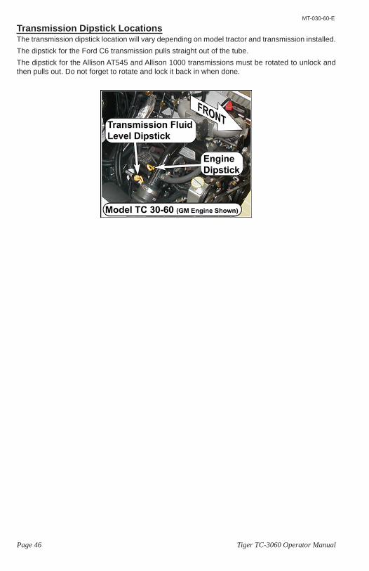
Page 46 Tiger TC-3060 Operator Manual
MT-030-60-E
Transmission Dipstick LocationsThe transmission dipstick location will vary depending on model tractor and transmission installed.The dipstick for the Ford C6 transmission pulls straight out of the tube.The dipstick for the Allison AT545 and Allison 1000 transmissions must be rotated to unlock and then pulls out. Do not forget to rotate and lock it back in when done.
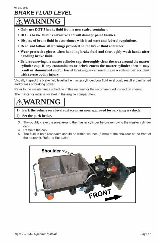
Page 47Tiger TC-3060 Operator Manual
MT-030-60-E
BRAKE FLUID LEVEL
Visually inspect the brake fluid level in the master cylinder. Low fluid level could result in diminished and/or loss of braking power.Refer to the maintenance schedule in this manual for the recommended inspection interval.The master cylinder is located in the engine compartment.
3. Thoroughly clean the area around the master cylinder before removing the master cylinder cap.
4. Remove the cap.5. The fluid in both reservoirs should be within 1/4 inch (6 mm) of the shoulder at the front of
the reservoir. Refer to illustration.
1) Park the vehicle on a level surface in an area approved for servicing a vehicle.2) Set the park brake.
WARNING
• Only use DOT 3 brake fluid from a new sealed container.• DOT 3 brake fluid is corrosive and will damage paint finishes.• Dispose of brake fluid in accordance with local state and federal regulations.• Read and follow all warnings provided on the brake fluid container.• Wear protective gloves when handling brake fluid and thoroughly wash hands after
handling brake fluid.• Before removing the master cylinder cap, thoroughly clean the area around the master
cylinder cap. If any contaminates or debris enters the master cylinder then it may result in diminished and/or loss of braking power resulting in a collision or accident with severe bodily injury.
WARNING
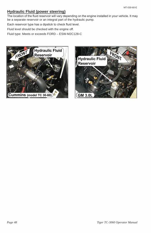
Page 48 Tiger TC-3060 Operator Manual
MT-030-60-E
Hydraulic Fluid (power steering)The location of the fluid reservoir will vary depending on the engine installed in your vehicle. It may be a separate reservoir or an integral part of the hydraulic pump.Each reservoir type has a dipstick to check fluid level.Fluid level should be checked with the engine off.Fluid type: Meets or exceeds FORD – ESW-M2C128-C
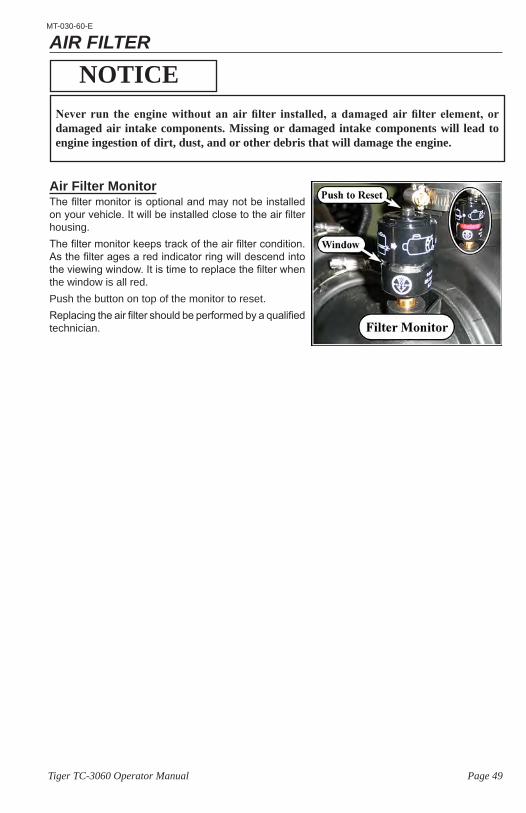
Page 49Tiger TC-3060 Operator Manual
MT-030-60-E
AIR FILTER
Air Filter MonitorThe filter monitor is optional and may not be installed on your vehicle. It will be installed close to the air filter housing.The filter monitor keeps track of the air filter condition. As the filter ages a red indicator ring will descend into the viewing window. It is time to replace the filter when the window is all red.Push the button on top of the monitor to reset.Replacing the air filter should be performed by a qualified technician.
Never run the engine without an air filter installed, a damaged air filter element, or damaged air intake components. Missing or damaged intake components will lead to engine ingestion of dirt, dust, and or other debris that will damage the engine.
NOTICE
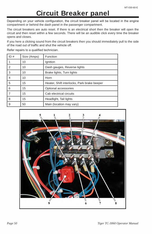
Page 50 Tiger TC-3060 Operator Manual
MT-030-60-E
Circuit Breaker panelDepending on your vehicle configuration, the circuit breaker panel will be located in the engine compartment or behind the dash panel in the passenger compartment.The circuit breakers are auto reset. If there is an electrical short then the breaker will open the circuit and then reset within a few seconds. There will be an audible click every time the breaker opens and closes.If you here a clicking sound from the circuit breakers then you should immediately pull to the side of the road out of traffic and shut the vehicle off.Refer repairs to a qualified technician.
ID # Size (Amps) Function
1 10 Ignition
2 10 Dash gauges, Reverse lights
3 10 Brake lights, Turn lights
4 10 Horn
5 15 Heater, Shift interlocks, Park brake beeper
6 15 Optional accessories
7 15 Cab electrical circuits
8 15 Headlight, Tail lights
9 50 Main (location may vary)
Page 51Tiger TC-3060 Operator Manual
MT-030-60-E
Battery Maintenance
• Battery electrolyte is poisonous and corrosive. It contains sulfuric acid. Avoid contact with skin, eyes, or clothing. Wear rubber gloves and face safety shield while servicing batteries. DO NOT INGEST! This will result in severe bodily injury.
• Wear a full face shield when working on or around batteries. A full face shield will help protect your eyes from battery electrolyte. If battery electrolyte gets in your eyes, immediately flush your eyes with large amounts of water and seek medical attention.
• Wear heavy duty long rubber gloves when working on or around batteries. If battery electrolyte gets on your skin, immediately flush with large amounts of water to prevent chemical burns.
• Explosive mixtures of Hydrogen gas are present within battery cells at all times. Do not work with or charge batteries in an area where open flames (including gas furnace or water heater pilots), sparks, cigarettes, or any other sources of combustion are present. Always provide ample ventilation in rooms where batteries are being charged. Failure to do so may result in severe bodily injury and/or property damage.
• Lead is poisonous. Batteries and battery terminals contain lead and lead components. Avoid touching the battery terminals and always thoroughly wash hands after servicing the batteries.
• A battery is a live electrical source. It cannot be disconnected or neutralized. Do not drop any tool or conductive object onto the battery. A conductive object that comes in contact with the battery terminals will initiate a short circuit of the battery. This could cause the battery to explode resulting in severe bodily injury and/or property damage.
• Do not leave cables on batteries that have been removed from the vehicle. Cables left on batteries could cause a short circuit resulting in battery explosion, severe bodily injury and/or property damage.
DANGER
• Battery electrolyte will stain and corrode most surfaces. Immediately and thoroughly clean any surface outside of the battery that the battery electrolyte comes in contact with. Failure to clean may result in property damage.
• When torquing battery hardware, use a backup wrench on the battery bolt and tighten the nut. Failure to use a backup wrench may damage the battery post.
• DO NOT remove the caps on a maintenance free battery. Removing the caps will damage or destroy the battery seals resulting in premature battery failure.
• Do not operate or charge a vehicle equipped with moist charged batteries until the batteries have been filled with electrolyte. Operating or charging moist charged batteries before filling with electrolyte will damage the batteries resulting in premature failure of the batteries.
NOTICE
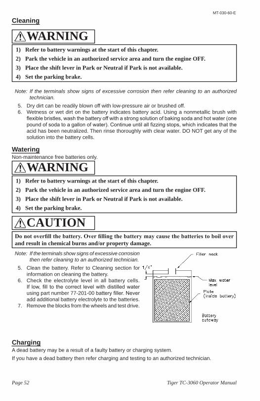
Page 52 Tiger TC-3060 Operator Manual
MT-030-60-E
Cleaning
Note: If the terminals show signs of excessive corrosion then refer cleaning to an authorized technician.
5. Dry dirt can be readily blown off with low-pressure air or brushed off. 6. Wetness or wet dirt on the battery indicates battery acid. Using a nonmetallic brush with
flexible bristles, wash the battery off with a strong solution of baking soda and hot water (one pound of soda to a gallon of water). Continue until all fizzing stops, which indicates that the acid has been neutralized. Then rinse thoroughly with clear water. DO NOT get any of the solution into the battery cells.
WateringNon-maintenance free batteries only.
Note: If the terminals show signs of excessive corrosion then refer cleaning to an authorized technician.
5. Clean the battery. Refer to Cleaning section for information on cleaning the battery.
6. Check the electrolyte level in all battery cells. If low, fill to the correct level with distilled water using part number 77-201-00 battery filler. Never add additional battery electrolyte to the batteries.
7. Remove the blocks from the wheels and test drive.
ChargingA dead battery may be a result of a faulty battery or charging system.If you have a dead battery then refer charging and testing to an authorized technician.
Do not overfill the battery. Over filling the battery may cause the batteries to boil over and result in chemical burns and/or property damage.
CAUTION
1) Refer to battery warnings at the start of this chapter.2) Park the vehicle in an authorized service area and turn the engine OFF.3) Place the shift lever in Park or Neutral if Park is not available.4) Set the parking brake.
WARNING
1) Refer to battery warnings at the start of this chapter.2) Park the vehicle in an authorized service area and turn the engine OFF.3) Place the shift lever in Park or Neutral if Park is not available.4) Set the parking brake.
WARNING
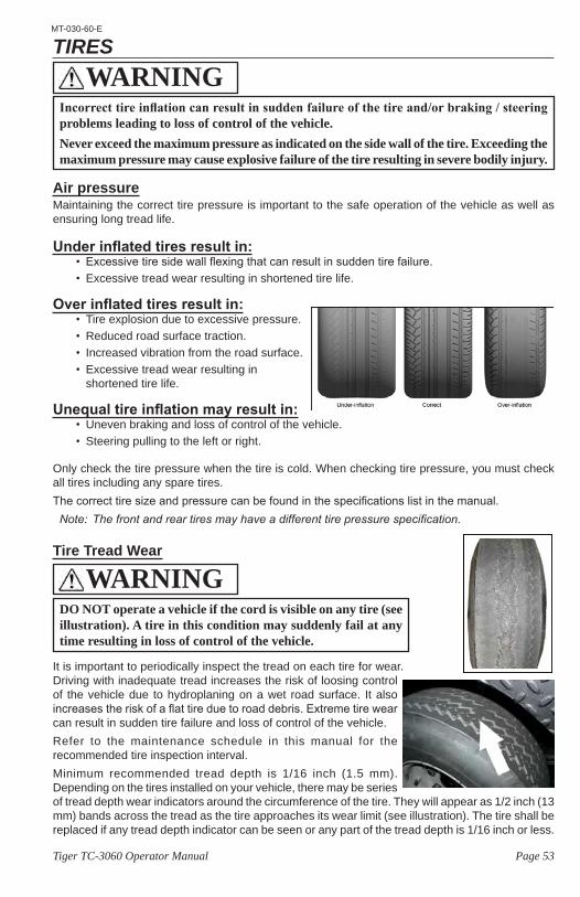
Page 53Tiger TC-3060 Operator Manual
MT-030-60-E
TIRES
Air pressureMaintaining the correct tire pressure is important to the safe operation of the vehicle as well as ensuring long tread life.
Under inflated tires result in:• Excessive tire side wall flexing that can result in sudden tire failure.• Excessive tread wear resulting in shortened tire life.
Over inflated tires result in:• Tire explosion due to excessive pressure.• Reduced road surface traction.• Increased vibration from the road surface.• Excessive tread wear resulting in
shortened tire life.
Unequal tire inflation may result in:• Uneven braking and loss of control of the vehicle.• Steering pulling to the left or right.
Only check the tire pressure when the tire is cold. When checking tire pressure, you must check all tires including any spare tires.The correct tire size and pressure can be found in the specifications list in the manual.Note: Thefrontandreartiresmayhaveadifferenttirepressurespecification.
Tire Tread Wear
It is important to periodically inspect the tread on each tire for wear. Driving with inadequate tread increases the risk of loosing control of the vehicle due to hydroplaning on a wet road surface. It also increases the risk of a flat tire due to road debris. Extreme tire wear can result in sudden tire failure and loss of control of the vehicle.Refer to the maintenance schedule in this manual for the recommended tire inspection interval.Minimum recommended tread depth is 1/16 inch (1.5 mm). Depending on the tires installed on your vehicle, there may be series of tread depth wear indicators around the circumference of the tire. They will appear as 1/2 inch (13 mm) bands across the tread as the tire approaches its wear limit (see illustration). The tire shall be replaced if any tread depth indicator can be seen or any part of the tread depth is 1/16 inch or less.
Incorrect tire inflation can result in sudden failure of the tire and/or braking / steering problems leading to loss of control of the vehicle.Never exceed the maximum pressure as indicated on the side wall of the tire. Exceeding the maximum pressure may cause explosive failure of the tire resulting in severe bodily injury.
WARNING
DO NOT operate a vehicle if the cord is visible on any tire (see illustration). A tire in this condition may suddenly fail at any time resulting in loss of control of the vehicle.
WARNING
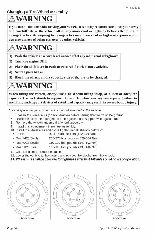
Page 54 Tiger TC-3060 Operator Manual
MT-030-60-E
Changing a Tire/Wheel assembly
Note: A spare tire, jack, or lug wrench is not attached to the vehicle.6. Loosen the wheel nuts (do not remove) before raising the tire off of the ground.7. Raise the tire to be changed off of the ground and support with a jack stand.8. Remove the wheel nuts and tire/wheel assembly.9. Install the replacement tire/wheel assembly.10. Install the wheel nuts and cross tighten per illustration below to:
• Front: 90-110 foot pounds (122-149 Nm) • Rear M20 Studs: 250-270 foot pounds (339-366 Nm)• Rear 9/16 Studs: 110-120 foot pounds (149-163 Nm)• Rear 1/2 Studs: 100-110 foot pounds (135-149 Nm)
11. Check the tire for proper inflation.12. Lower the vehicle to the ground and remove the blocks from the wheels.13. Wheel nuts shall be checked for tightness after first 100 miles or 24 hours of operation.
1) Park the vehicle on a hard level surface off of any main road or highway.2) Turn the engine OFF.3) Place the shift lever in Park or Neutral if Park is not available.4) Set the park brake.5) Block the wheels on the opposite side of the tire to be changed.
WARNING
When lifting the vehicle, always use a hoist with lifting strap, or a jack of adequate capacity. Use jack stands to support the vehicle before starting any repairs. Failure to use lifting and support devices of rated load capacity may result in severe bodily injury.
WARNING
If you have a flat tire while driving your vehicle, it is highly recommended that you slowly and carefully drive the vehicle off of any main road or highway before attempting to change the tire. Attempting to change a tire on a main road or highway exposes you to extreme danger of being run over by other vehicles.
WARNING
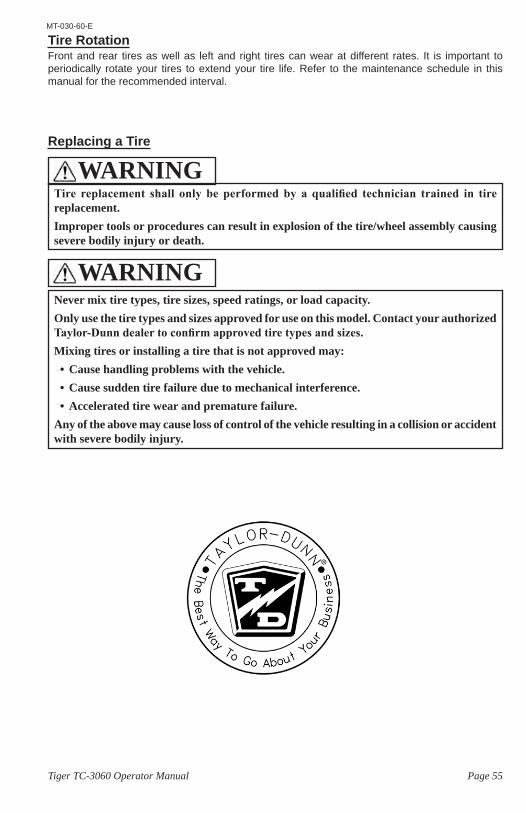
Page 55Tiger TC-3060 Operator Manual
MT-030-60-E
Tire RotationFront and rear tires as well as left and right tires can wear at different rates. It is important to periodically rotate your tires to extend your tire life. Refer to the maintenance schedule in this manual for the recommended interval.
Replacing a Tire
Tire replacement shall only be performed by a qualified technician trained in tire replacement.Improper tools or procedures can result in explosion of the tire/wheel assembly causing severe bodily injury or death.
WARNING
Never mix tire types, tire sizes, speed ratings, or load capacity.Only use the tire types and sizes approved for use on this model. Contact your authorized Taylor-Dunn dealer to confirm approved tire types and sizes.Mixing tires or installing a tire that is not approved may:• Cause handling problems with the vehicle.• Cause sudden tire failure due to mechanical interference.• Accelerated tire wear and premature failure.
Any of the above may cause loss of control of the vehicle resulting in a collision or accident with severe bodily injury.
WARNING
Page 56 Tiger TC-3060 Operator Manual
MT-030-60-E
CLEANINGGlassThe front, rear, and hard door windows are made of standard automotive glass and can be cleaned with any standard household glass cleaner.
Plastic WindowsSoft door windows are made of clear soft plastic that is easily scratched and can be damaged from some cleansers or solvents. To remove any road tar or grease, Use a 70% isopropyl alcohol solution and soft cloth then wash with water and dry with a soft cloth.
• Do not use any abrasives or abrasive cleaners.
• Do not use any chemical cleaners or cleaning solvents.
Seats / Soft DoorsClean your seats with any standard automotive vinyl cleaner.
Interior
Use a mild liquid detergent in warm water to wipe down the interior of your vehicle.
Exterior Body
Use any standard automotive exterior car wash solution. Do not use any abrasive cloths or cleaners.Finish with a quality automotive wax to preserve the finish of your vehicle.
Cleaning the Seat BeltsClean the safety belts with any mild soap solution that is recommended for cleaning upholstery or carpets. Do not bleach or dye the belt webbing because this may weaken it.
Under CarriageFor long life, it is important to keep the under carriage of the vehicle clean from caked on dirt, mud, or road salt. Any of these substances will cause accelerated corrosion of the frame and lead to premature failure.When cleaning the under carriage, be careful not to get any cleaning solutions or excessive water into any electrical compartments.
BatteryRefer to the Battery Maintenance section.
NOTICEDO NOT spray the interior with water. Large amounts of water may damage the electronics in the dash.
NOTICEDO NOT use an automated car wash facility of any type. This vehicle is not designed to fit in any automated car wash and it is likely that the vehicle will be damaged.
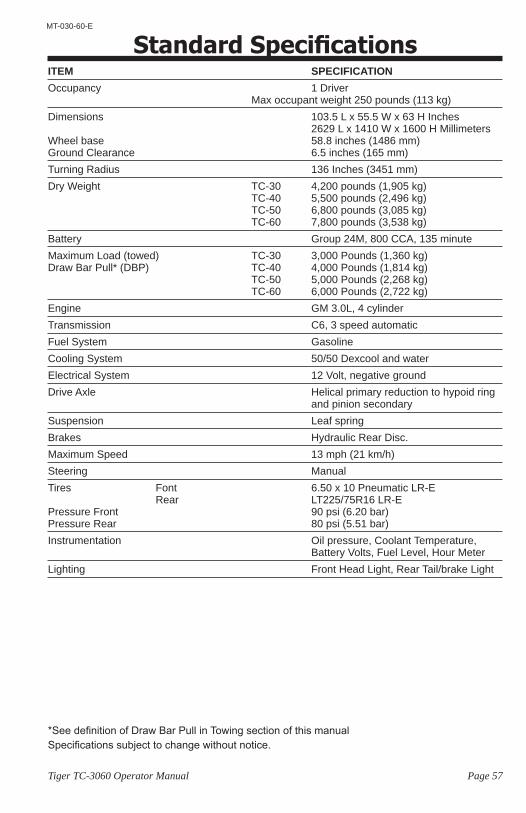
Page 57Tiger TC-3060 Operator Manual
MT-030-60-E
Standard SpecificationsITEM SPECIFICATIONOccupancy 1 Driver Max occupant weight 250 pounds (113 kg)Dimensions 103.5 L x 55.5 W x 63 H Inches 2629 L x 1410 W x 1600 H Millimeters Wheel base 58.8 inches (1486 mm) Ground Clearance 6.5 inches (165 mm)Turning Radius 136 Inches (3451 mm)Dry Weight TC-30 4,200 pounds (1,905 kg) TC-40 5,500 pounds (2,496 kg) TC-50 6,800 pounds (3,085 kg) TC-60 7,800 pounds (3,538 kg)Battery Group 24M, 800 CCA, 135 minuteMaximum Load (towed) TC-30 3,000 Pounds (1,360 kg) Draw Bar Pull* (DBP) TC-40 4,000 Pounds (1,814 kg) TC-50 5,000 Pounds (2,268 kg) TC-60 6,000 Pounds (2,722 kg)Engine GM 3.0L, 4 cylinderTransmission C6, 3 speed automaticFuel System GasolineCooling System 50/50 Dexcool and waterElectrical System 12 Volt, negative ground Drive Axle Helical primary reduction to hypoid ring and pinion secondarySuspension Leaf springBrakes Hydraulic Rear Disc.Maximum Speed 13 mph (21 km/h) Steering ManualTires Font 6.50 x 10 Pneumatic LR-E Rear LT225/75R16 LR-E Pressure Front 90 psi (6.20 bar) Pressure Rear 80 psi (5.51 bar)Instrumentation Oil pressure, Coolant Temperature, Battery Volts, Fuel Level, Hour MeterLighting Front Head Light, Rear Tail/brake Light
Specifications subject to change without notice.*See definition of Draw Bar Pull in Towing section of this manual
Index 58
IndexA
Accidents 32Air Filter
Monitor 49Approved Operator Position 8Auto Crank 28
BBattery
Charging 52Cleaning 52Maintenance 51Watering 52
Battery filler 52Brake
Foot 20Parking 20
Brake Fluid 47
CCircuit Breaker 50Cleaning
Batteries 56Battery Charger 56Control Panel 56Exterior Body 56Glass 56Interior 56Plastic Windows 56Seats 56Soft Doors 56Under Carriage 56
Collisions 32Coolant, Engine 41Coolant Specifications 44
DDaily Inspection 38Data plate 14Dealer locator 3Decals 9Dipstick
Engine Oil 42Transmission 46
Draw Bar Pull 33Driving 30
Parking 32Reversing Direction 31Selecting Gear Range 31Stopping 32
EEngine
Oil Type 41Starting 27Stopping 27
FFeedback 3Fluid Levels
Coolant 41Engine Oil 41Hydraulic Fluid 48Power Steering 48Transmission 45
Foot brake pedal 20Fuel
Diesel 36Gasohol 36Gasoline 35
LPG 36Fuel Gauge 19Fuse (Circuit Breakers) 50
GGauge
Coolant Temperature 19Fuel 19Oil Pressure 19Volt Meter 19
Glossary of Terms 8
HHeadlight Switch 19Horn Switch 21Hour Meter 19
IIdentify
Engine 15Transmission 15Vehicle 14
Interlock Switch Inspection 39
LLamp
Shift Inhibit 31Licensing
Vehicle 13
MMaintenance
Battery 51Pre-Operation Inspection 38Schedule 40Severe Duty 40
Modifications 11, 12
OOperator Training 10, 17OPS 8
PParking 32Parking Brake 20, 22Pedal
Foot Brake 20Throttle 20
Pre-Operation Inspection 38
RRefueling 28Replacement Parts 12Returning to Service 37
SSeat Belts 25
Cleaning 56Lap Belt 26Maintenance 26Shoulder Belt 26Use 25While Pregnant 26
Serial Number, Vehicle 14Severe Duty 40Shift Lever 20, 22Signal Words
Caution 9
Danger 9Notice 9Warning 9
Specifications 57Starting the Engine 27
Diesel 27Gasoline 27Jump Starting 29LPG 28
Steering 21Stopping 32Stopping the Engine 28
Diesel 28Gasoline 28LPG 28
Storing 37Switch
Directional 20Emergency Engine Kill 32Hazard (4-way) 20Horn 21Ignition 19Lights 19Operator Presence 21
TTip Over 25Tires
Air Pressure 53Changing 54Replacing 55Rotation 55Tread Wear 53
TowingTrailer 33Vehicle 34
Training 10Maintenance 10Operator 10, 17Service 10
Transmission Fluid Specifications 45Transmission Fluid, Type 45Transmission Shift Lever 22
VVehicle Operation 23
Driving 30Parking 32Starting 27Stopping 32Towing Trailers 33
WWarning icons 9Web site, Taylor-Dunn 17Welding 11
Page 59Tiger TC-3060 Operator Manual
MT-030-60-E
Page 60 Tiger TC-3060 Operator Manual
MT-030-60-E
Taylor-Dunn® Mfg.2114 W. Ball Rd. Anaheim, CA 92804 (800)-688-8680(714) 956-4040 (FAX) (714) 956-0504
Visit our Web site: www.taylor-dunn.com
Operating, servicing and maintaining a passenger vehicle or off-highway motor vehicle can expose you to chemicals including engine exhaust, carbon monoxide, phthalates, and lead, which are known to the State of California to cause cancer and birth defects or other reproductive harm. To minimize exposure, avoid breathing exhaust, do not idle the engine except as necessary, service your vehicle in a well-ventilated area and wear gloves or wash your hands frequently when servicing your vehicle. For more information go to www.P65Warnings.ca.gov/passenger-vehicle.
WARNING