Embed Size (px)
DESCRIPTION
maquinas ambasador
Citation preview

Ambassador BenchTop EGM
Operators Manual
INTERNATIONAL SAS
Copyright © 2004
Ainsworth Game Technology Limited All Rights Reserved
ACN 068 516 665
ABN 37 068 516 665

Copyright Information
Ainsworth Game Technology Limited claims copyright on each page of this document. The right to reproduce, distribute, display and make derivative works from this document, or any portion thereof requires approval from Ainsworth Game Technology Limited.
For more information contact:
Ainsworth Game Technology Limited, ACN 068 516 665
10 Holker Street, Newington
Sydney, NSW 2127 Australia
Phone 02 9739 8000—International +61 2 9739 8000
Fax 02 9737 9483—International +61 2 9737 9483
Email [email protected]
Ambassador BenchTop Operators Manual Ainsworth Game Technology Limited ii
Table of Contents
1 ..................................................................................................1 Introduction....................................................................................................................1
Operator’s Manual Contents ................................................................................................................ 2 Specifications ........................................................................................................................................ 3
Configuration..................................................................................................................................................... 3 Physical.............................................................................................................................................................. 3 Electrical ............................................................................................................................................................ 3 Environmental.................................................................................................................................................... 3 Standards of Compliance ................................................................................................................................... 3
2 ..................................................................................................4 Description.....................................................................................................................4
Introduction............................................................................................................................................ 4 Physical Description ............................................................................................................................. 4 External Components ........................................................................................................................... 6
Cabinet Body Assembly .................................................................................................................................... 6 Main Door Assembly and Controls ................................................................................................................... 7 Button Panel....................................................................................................................................................... 8 Monitor Assembly ............................................................................................................................................. 8 Coin Validator ................................................................................................................................................. 10
Internal Components .......................................................................................................................... 11 Banknote Validator Assembly ......................................................................................................................... 11 Player Tracking Module .................................................................................................................................. 13 Logic Cage Assembly...................................................................................................................................... 13
Basic Operation................................................................................................................................... 14 Game Display .................................................................................................................................................. 14
3 ................................................................................................16 Operating Modes .........................................................................................................16
Introduction.......................................................................................................................................... 16 Play Mode............................................................................................................................................. 16
Game Rules...................................................................................................................................................... 17 Operator Modes................................................................................................................................... 18
General............................................................................................................................................................. 18 Cancel Credit ................................................................................................................................................... 19 Audit ................................................................................................................................................................ 19
Audit Mode........................................................................................................................................... 21 Game History................................................................................................................................................... 21 Machine Identification..................................................................................................................................... 26 Metering Information....................................................................................................................................... 27 Configuration Information............................................................................................................................... 28 Configuration Mode......................................................................................................................................... 29 Machine Configuration Set-up......................................................................................................................... 29 Validation Configuration Sub Menu................................................................................................................ 31 Tower Light Configuration Sub Menu............................................................................................................. 31 Sound System Setup ........................................................................................................................................ 32 Real Time Clock Setup .................................................................................................................................... 33 Banknote Meters - History............................................................................................................................... 34 Ticket In History.............................................................................................................................................. 35 Ticket Out History ........................................................................................................................................... 35 Game Statistics Page........................................................................................................................................ 36 Hopper Refill Mode......................................................................................................................................... 37
Ambassador BenchTop Operators Manual Ainsworth Game Technology Limited iii
Revision Records
Power Save Mode ............................................................................................................................................ 38 Pending Faults / Disabling Conditions............................................................................................................. 38 Image Validation Menu ................................................................................................................................... 39 Bonus History .................................................................................................................................................. 39 Multiplied Jackpot History .............................................................................................................................. 40
Test Mode............................................................................................................................................. 41 Device Tests..................................................................................................................................................... 42 Hopper Test ..................................................................................................................................................... 42 Coin In Validation Test.................................................................................................................................... 44 Banknote Validator Test .................................................................................................................................. 45 Video Test........................................................................................................................................................ 46 Sound Test ....................................................................................................................................................... 47 Button / Key Test............................................................................................................................................. 49 Lamp Test ........................................................................................................................................................ 49 Door Status Test .............................................................................................................................................. 50 Diverter Test .................................................................................................................................................... 50 Miscellaneous Input Test ................................................................................................................................. 51 NVRAM Test................................................................................................................................................... 53 Game Combination Test .................................................................................................................................. 54
4 ................................................................................................55 Operator Routine Servicing ........................................................................................55
General Maintenance .......................................................................................................................... 55 Cabinet Body Cleaning ....................................................................................................................... 55 Main Door Cleaning............................................................................................................................. 55 Monitor Cleaning ................................................................................................................................. 56 Banknote Stacker Assembly .............................................................................................................. 56
Removing and Replacing the Banknote Stacker.............................................................................................. 56 Removing, Dismantling and Replacing the Banknote Validator ..................................................................... 56 Banknote Validator Jam Clearing.................................................................................................................... 59 Banknote Validator Cleaning........................................................................................................................... 59 Banknote Validator Test .................................................................................................................................. 60
Coin Validator ...................................................................................................................................... 61 Coin Validator Cleaning .................................................................................................................................. 61
Hopper Servicing................................................................................................................................. 63 Printer Service ..................................................................................................................................... 64 Fuse Replacement............................................................................................................................... 69 Button LED Replacement ................................................................................................................... 69 Error Messages.................................................................................................................................... 70
Ambassador BenchTop Operators Manual Ainsworth Game Technology Limited iv
Chapter
INTRODUCTION This Operator’s Manual is for use by operators of the approved EGM, which is identified on the cover page. Service personnel without appropriate qualifications and training should not attempt to carry out additional servicing. To do so may result in injury to personnel, damage to equipment, and voiding of the warranty. Such actions may also contravene jurisdictional regulations.
There are two manuals associated with the EGM. The manuals that form the suite for the approved EGM are:
• Operator’s Manual — Intended for use by operators in the routine servicing and operation of the approved EGM.
• Installation and Service Manual — Intended for use by qualified service personnel for the installation, testing and troubleshooting of the approved EGM.
Ambassador BenchTop Operators Manual Ainsworth Game Technology Limited 1
Chapter 1: Introduction — Operator’s Manual Contents
Operator’s Manual Contents Description
The Description chapter covers the components and basic operation of the EGM to enable you to familiarise yourself with the machine. This chapter also includes specifications of the approved EGM relating to weight, physical size, environmental operating envelope, basic operation and functional description.
Operating Modes
The Operation chapter includes information about the various modes the machine operates in and how to use them.
Operator Routine Servicing
This chapter provides routine maintenance procedures for the machine and its components. These procedures are the responsibility of the machine’s operator or their service agent.
Ambassador BenchTop Operators Manual Ainsworth Game Technology Limited 2
Chapter 1: Introduction — Specifications
Specifications The following information is provided for the Installation Technician on machine configuration, the physical, electrical, and environmental specifications of the machine, and the standards to which the machine complies.
Configuration The machines are configured on site during installation. However some settings cannot be altered once the jurisdictional authority has approved the machine.
Physical The machine is 1236 mm high by 540 mm wide by 695 mm deep. It weighs 140 kg.
The weight is for the basic configuration only. Where options have been fitted their individual weights must be added.
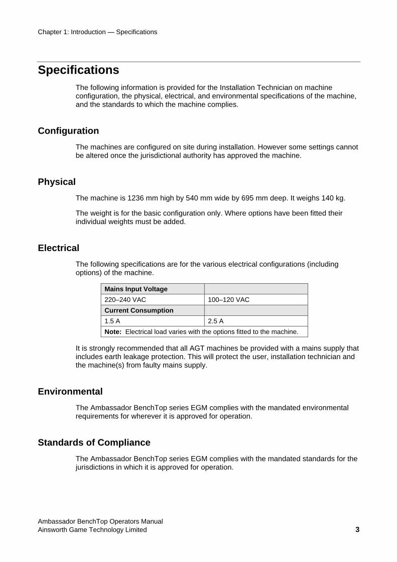
Electrical The following specifications are for the various electrical configurations (including options) of the machine.
Mains Input Voltage 220–240 VAC 100–120 VAC Current Consumption 1.5 A 2.5 A Note: Electrical load varies with the options fitted to the machine.
It is strongly recommended that all AGT machines be provided with a mains supply that includes earth leakage protection. This will protect the user, installation technician and the machine(s) from faulty mains supply.
Environmental The Ambassador BenchTop series EGM complies with the mandated environmental requirements for wherever it is approved for operation.
Standards of Compliance The Ambassador BenchTop series EGM complies with the mandated standards for the jurisdictions in which it is approved for operation.
Ambassador BenchTop Operators Manual Ainsworth Game Technology Limited 3
Chapter
DESCRIPTION
Introduction This chapter provides a physical description of the machine and its components, describes the basic operation of the machine, and lists its operating specifications.
Physical Description The following is a list of the major components (in bold) and their related sub assemblies. Each part is described in detail in the following pages.
Cabinet Body Assembly
• Left Side Panel
o Loudspeaker
• Right Side Panel
o Loudspeaker
o EGM Serial Number and Compliance Plate
o Main Door Lock
o Main Door Release
o Credit Reset/Audit Key Switch
• Back Panel
• Monitor Shelf
• Main Door Assembly and Controls
• Player Tracking Module (if fitted)
Monitor Assembly
• Monitor Mask
Ambassador BenchTop Operators Manual Ainsworth Game Technology Limited 4
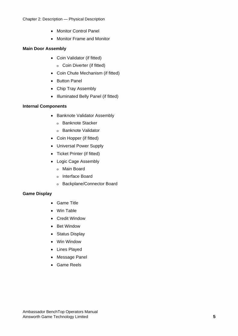
Chapter 2: Description — Physical Description
• Monitor Control Panel
• Monitor Frame and Monitor
Main Door Assembly
• Coin Validator (if fitted)
o Coin Diverter (if fitted)
• Coin Chute Mechanism (if fitted)
• Button Panel
• Chip Tray Assembly
• Illuminated Belly Panel (if fitted)
Internal Components
• Banknote Validator Assembly
o Banknote Stacker
o Banknote Validator
• Coin Hopper (if fitted)
• Universal Power Supply
• Ticket Printer (if fitted)
• Logic Cage Assembly
o Main Board
o Interface Board
o Backplane/Connector Board
Game Display
• Game Title
• Win Table
• Credit Window
• Bet Window
• Status Display
• Win Window
• Lines Played
• Message Panel
• Game Reels
Ambassador BenchTop Operators Manual Ainsworth Game Technology Limited 5
Chapter 2: Description — External Components
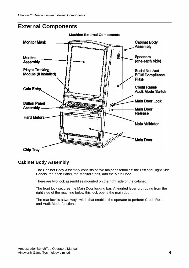
External Components Machine External Components
Cabinet Body Assembly The Cabinet Body Assembly consists of five major assemblies: the Left and Right Side Panels, the back Panel, the Monitor Shelf, and the Main Door.
There are two lock assemblies mounted on the right side of the cabinet.
The front lock secures the Main Door locking bar. A knurled lever protruding from the right side of the machine below this lock opens the main door.
The rear lock is a two-way switch that enables the operator to perform Credit Reset and Audit Mode functions.
Ambassador BenchTop Operators Manual Ainsworth Game Technology Limited 6
Chapter 2: Description — External Components
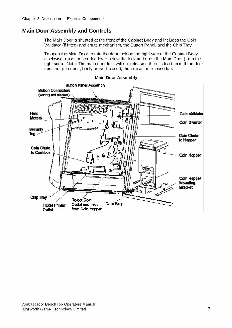
Main Door Assembly and Controls The Main Door is situated at the front of the Cabinet Body and includes the Coin Validator (if fitted) and chute mechanism, the Button Panel, and the Chip Tray.
To open the Main Door, rotate the door lock on the right side of the Cabinet Body clockwise, raise the knurled lever below the lock and open the Main Door (from the right side). Note: The main door lock will not release if there is load on it. If the door does not pop open, firmly press it closed, then raise the release bar.
Main Door Assembly
Ambassador BenchTop Operators Manual Ainsworth Game Technology Limited 7
Chapter 2: Description — External Components
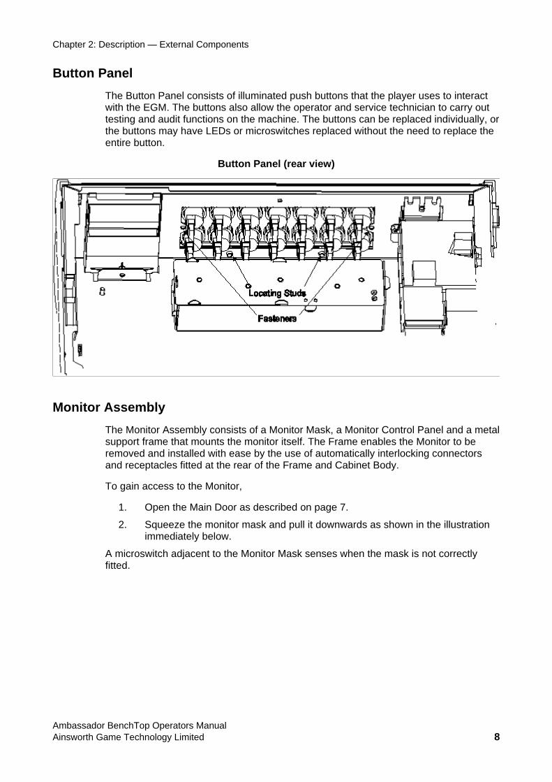
Button Panel The Button Panel consists of illuminated push buttons that the player uses to interact with the EGM. The buttons also allow the operator and service technician to carry out testing and audit functions on the machine. The buttons can be replaced individually, or the buttons may have LEDs or microswitches replaced without the need to replace the entire button.
Button Panel (rear view)
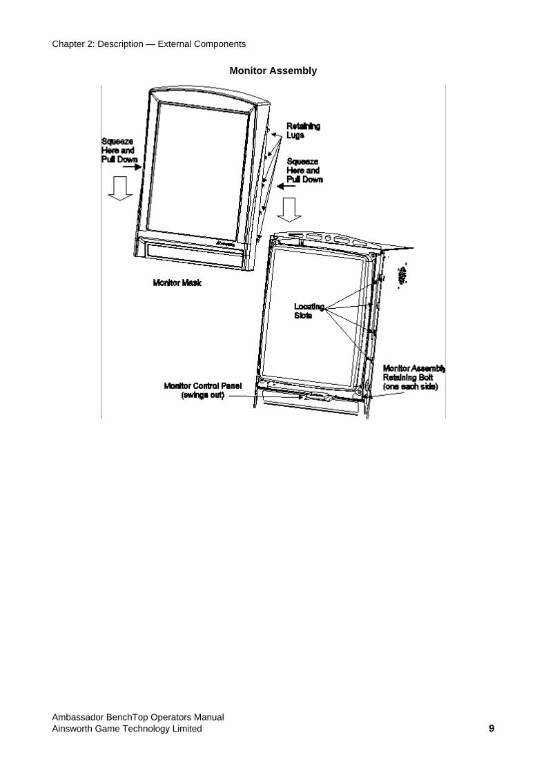
Monitor Assembly The Monitor Assembly consists of a Monitor Mask, a Monitor Control Panel and a metal support frame that mounts the monitor itself. The Frame enables the Monitor to be removed and installed with ease by the use of automatically interlocking connectors and receptacles fitted at the rear of the Frame and Cabinet Body.
To gain access to the Monitor,
1. Open the Main Door as described on page 7.
2. Squeeze the monitor mask and pull it downwards as shown in the illustration immediately below.
A microswitch adjacent to the Monitor Mask senses when the mask is not correctly fitted.
Ambassador BenchTop Operators Manual Ainsworth Game Technology Limited 8
Chapter 2: Description — External Components
Monitor Assembly
Ambassador BenchTop Operators Manual Ainsworth Game Technology Limited 9
Chapter 2: Description — External Components
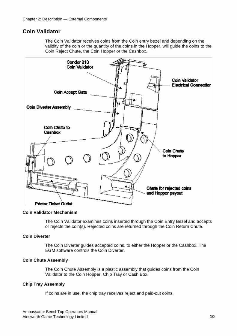
Coin Validator The Coin Validator receives coins from the Coin entry bezel and depending on the validity of the coin or the quantity of the coins in the Hopper, will guide the coins to the Coin Reject Chute, the Coin Hopper or the Cashbox.
Coin Validator Mechanism
The Coin Validator examines coins inserted through the Coin Entry Bezel and accepts or rejects the coin(s). Rejected coins are returned through the Coin Return Chute.
Coin Diverter
The Coin Diverter guides accepted coins, to either the Hopper or the Cashbox. The EGM software controls the Coin Diverter.
Coin Chute Assembly
The Coin Chute Assembly is a plastic assembly that guides coins from the Coin Validator to the Coin Hopper, Chip Tray or Cash Box.
Chip Tray Assembly
If coins are in use, the chip tray receives reject and paid-out coins.
Ambassador BenchTop Operators Manual Ainsworth Game Technology Limited 10
Chapter 2: Description — Internal Components
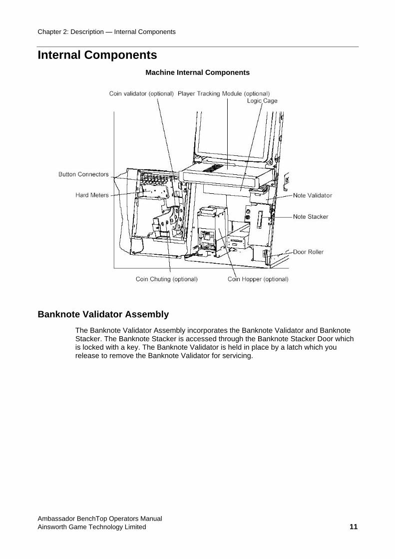
Internal Components Machine Internal Components
Banknote Validator Assembly The Banknote Validator Assembly incorporates the Banknote Validator and Banknote Stacker. The Banknote Stacker is accessed through the Banknote Stacker Door which is locked with a key. The Banknote Validator is held in place by a latch which you release to remove the Banknote Validator for servicing.
Ambassador BenchTop Operators Manual Ainsworth Game Technology Limited 11
Chapter 2: Description — Internal Components
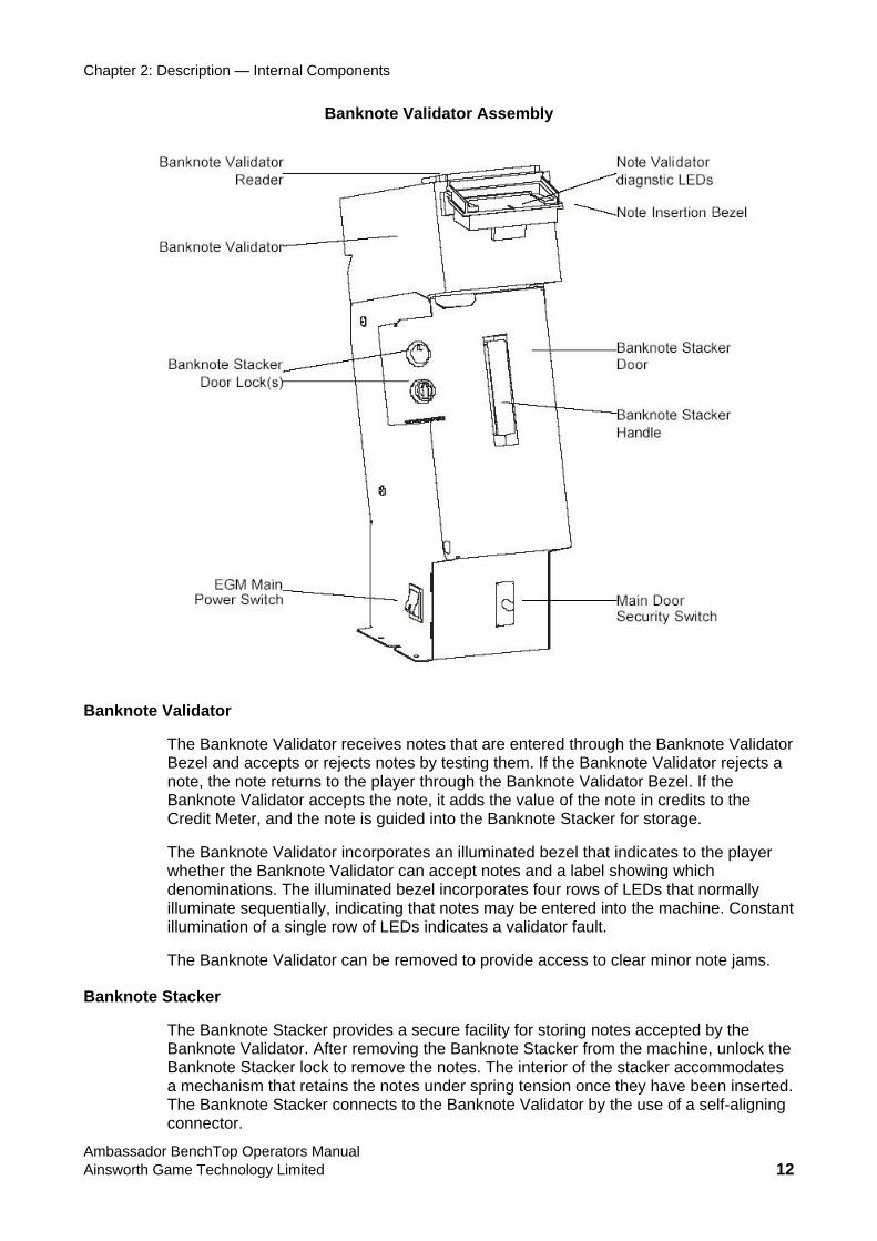
Banknote Validator Assembly
Banknote Validator
The Banknote Validator receives notes that are entered through the Banknote Validator Bezel and accepts or rejects notes by testing them. If the Banknote Validator rejects a note, the note returns to the player through the Banknote Validator Bezel. If the Banknote Validator accepts the note, it adds the value of the note in credits to the Credit Meter, and the note is guided into the Banknote Stacker for storage.
The Banknote Validator incorporates an illuminated bezel that indicates to the player whether the Banknote Validator can accept notes and a label showing which denominations. The illuminated bezel incorporates four rows of LEDs that normally illuminate sequentially, indicating that notes may be entered into the machine. Constant illumination of a single row of LEDs indicates a validator fault.
The Banknote Validator can be removed to provide access to clear minor note jams.
Banknote Stacker
The Banknote Stacker provides a secure facility for storing notes accepted by the Banknote Validator. After removing the Banknote Stacker from the machine, unlock the Banknote Stacker lock to remove the notes. The interior of the stacker accommodates a mechanism that retains the notes under spring tension once they have been inserted. The Banknote Stacker connects to the Banknote Validator by the use of a self-aligning connector.
Ambassador BenchTop Operators Manual Ainsworth Game Technology Limited 12
Chapter 2: Description — Internal Components
Player Tracking Module Space is provided above the player pushbuttons for an optional Player Tracking Module: refer to the module manufacturer’s documentation for more information.
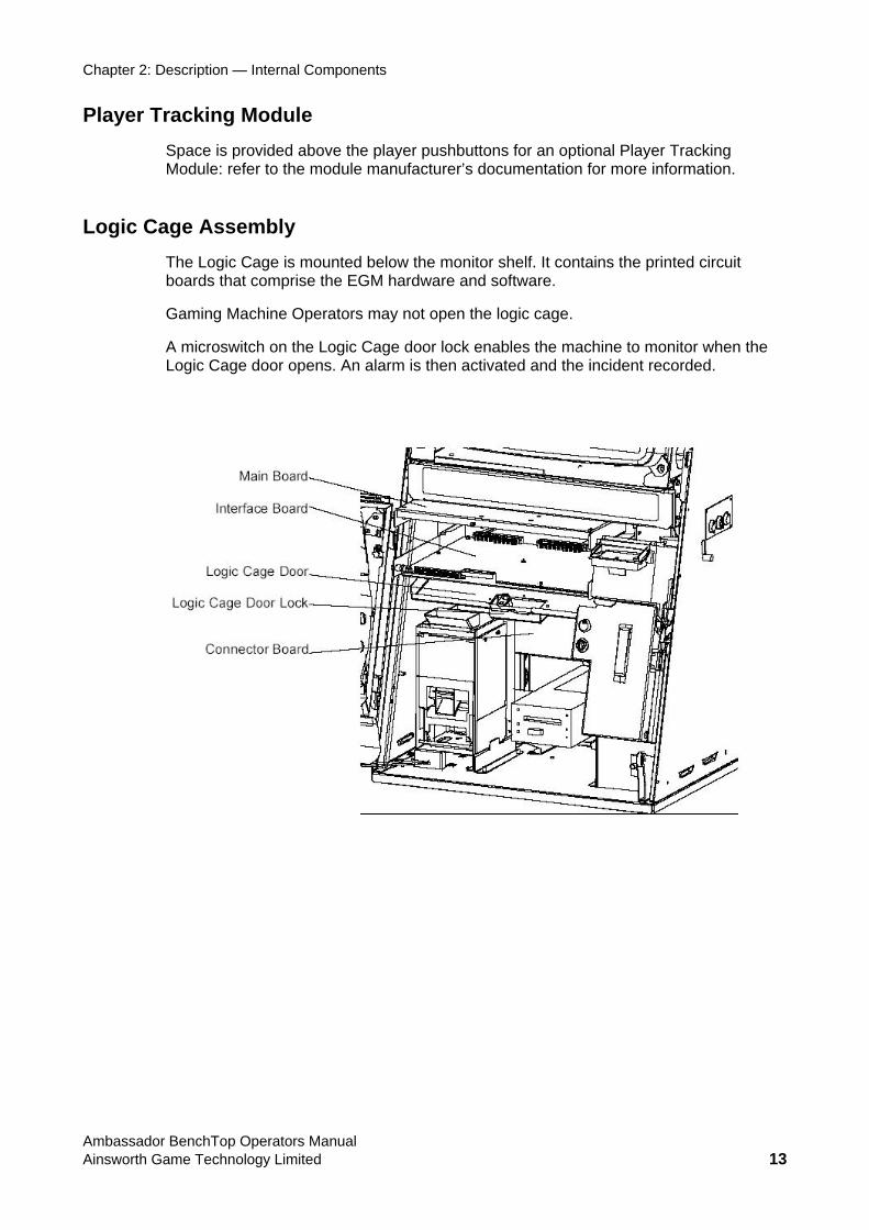
Logic Cage Assembly The Logic Cage is mounted below the monitor shelf. It contains the printed circuit boards that comprise the EGM hardware and software.
Gaming Machine Operators may not open the logic cage.
A microswitch on the Logic Cage door lock enables the machine to monitor when the Logic Cage door opens. An alarm is then activated and the incident recorded.
Ambassador BenchTop Operators Manual Ainsworth Game Technology Limited 13
Chapter 2: Description — Basic Operation
Basic Operation When the machine has been set up, turn it on using the Mains on/off control switch at the base of the Banknote Acceptor housing. When the machine is switched on it undergoes an initialisation sequence where many testing functions are carried out automatically. If the machine passes the self auditing tests during initialisation the Game Display screen will be automatically displayed after approximately 20 seconds.
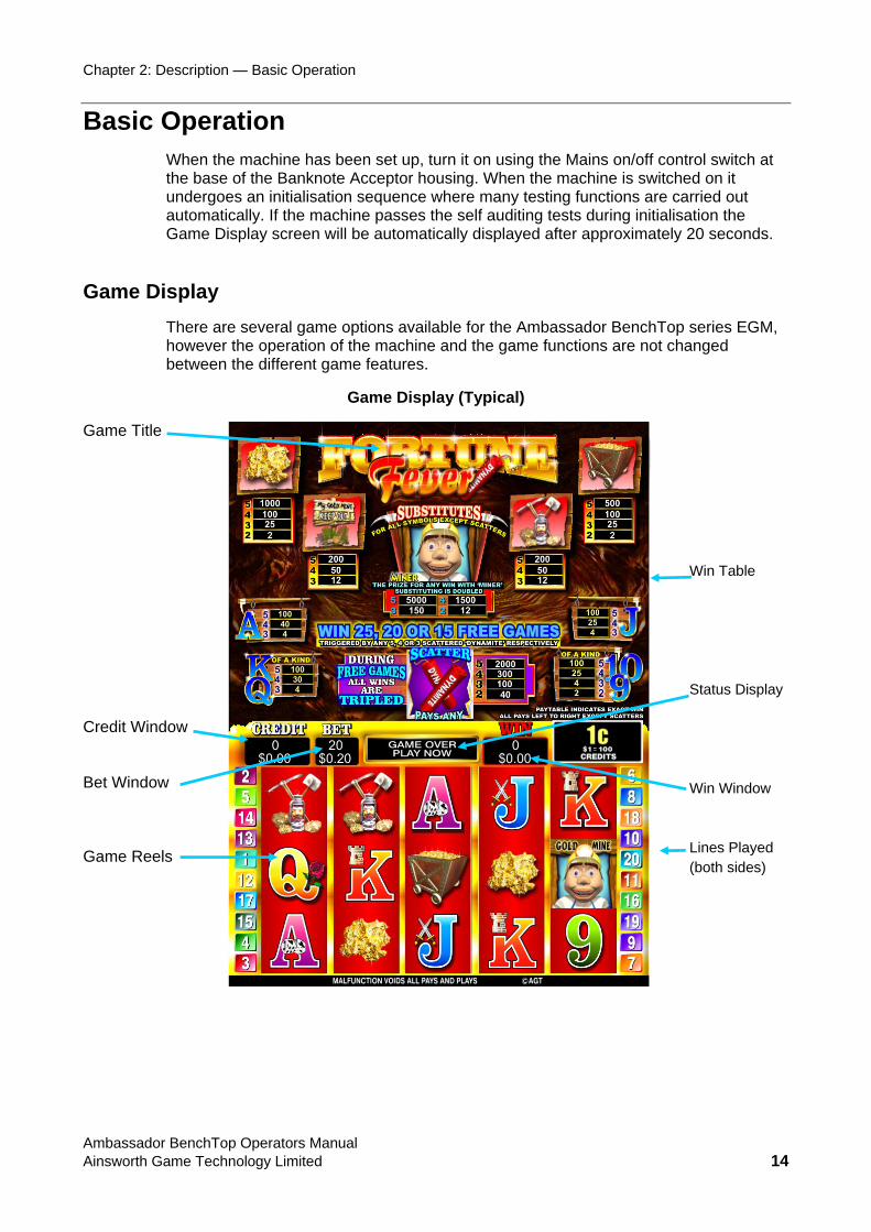
Game Display There are several game options available for the Ambassador BenchTop series EGM, however the operation of the machine and the game functions are not changed between the different game features.
Game Display (Typical)
Game Title Credit Window Bet Window Game Reels
Win Table Status Display Win Window Lines Played (both sides)
Ambassador BenchTop Operators Manual Ainsworth Game Technology Limited 14
Chapter 2: Description — Basic Operation
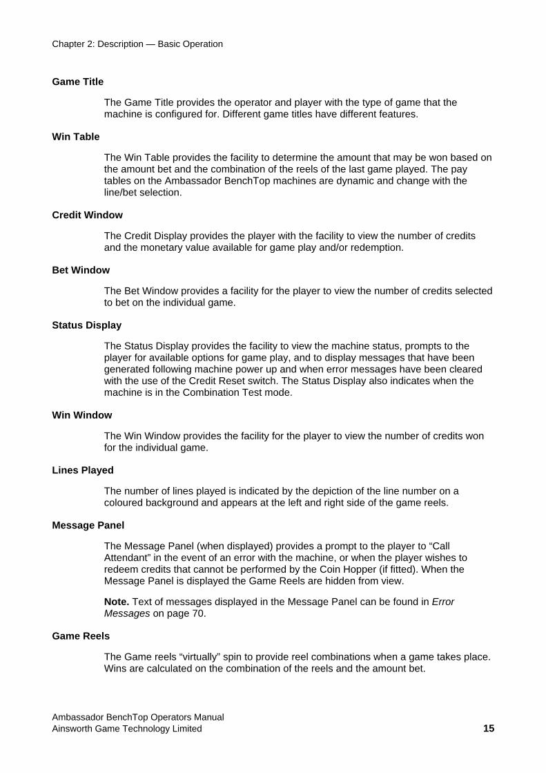
Game Title
The Game Title provides the operator and player with the type of game that the machine is configured for. Different game titles have different features.
Win Table
The Win Table provides the facility to determine the amount that may be won based on the amount bet and the combination of the reels of the last game played. The pay tables on the Ambassador BenchTop machines are dynamic and change with the line/bet selection.
Credit Window
The Credit Display provides the player with the facility to view the number of credits and the monetary value available for game play and/or redemption.
Bet Window
The Bet Window provides a facility for the player to view the number of credits selected to bet on the individual game.
Status Display
The Status Display provides the facility to view the machine status, prompts to the player for available options for game play, and to display messages that have been generated following machine power up and when error messages have been cleared with the use of the Credit Reset switch. The Status Display also indicates when the machine is in the Combination Test mode.
Win Window
The Win Window provides the facility for the player to view the number of credits won for the individual game.
Lines Played
The number of lines played is indicated by the depiction of the line number on a coloured background and appears at the left and right side of the game reels.
Message Panel
The Message Panel (when displayed) provides a prompt to the player to “Call Attendant” in the event of an error with the machine, or when the player wishes to redeem credits that cannot be performed by the Coin Hopper (if fitted). When the Message Panel is displayed the Game Reels are hidden from view.
Note. Text of messages displayed in the Message Panel can be found in Error Messages on page 70.
Game Reels
The Game reels “virtually” spin to provide reel combinations when a game takes place. Wins are calculated on the combination of the reels and the amount bet.
Ambassador BenchTop Operators Manual Ainsworth Game Technology Limited 15
Chapter
OPERATING MODES
Introduction This chapter provides information relating to the various operating modes of the machine and is divided into Play Mode and Operator Modes (incorporating Audit Mode, Configuration Modes and Test Modes).
Play Mode The machine can be deemed to be in Play Mode when the machine is turned on (and initialisation has taken place), the Main Door is closed and locked and no active lockup conditions exist.
Indications that the game is available for play are the illumination of the lamps in the buttons on the Button Panel to attract player attention. Other visual indications include “PLAY NOW” being displayed in the Status Display and the absence of the Message Panel display (which would obscure the game reels).
Ambassador BenchTop Operators Manual Ainsworth Game Technology Limited 16
Chapter 3: Operating Modes — Play Mode
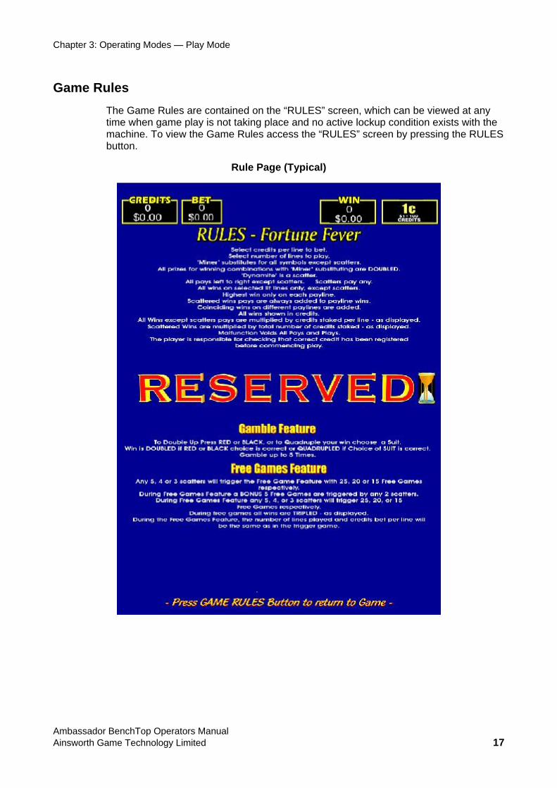
Game Rules The Game Rules are contained on the “RULES” screen, which can be viewed at any time when game play is not taking place and no active lockup condition exists with the machine. To view the Game Rules access the “RULES” screen by pressing the RULES button.
Rule Page (Typical)
Ambassador BenchTop Operators Manual Ainsworth Game Technology Limited 17
Chapter 3: Operating Modes — Operator Modes
Operator Modes
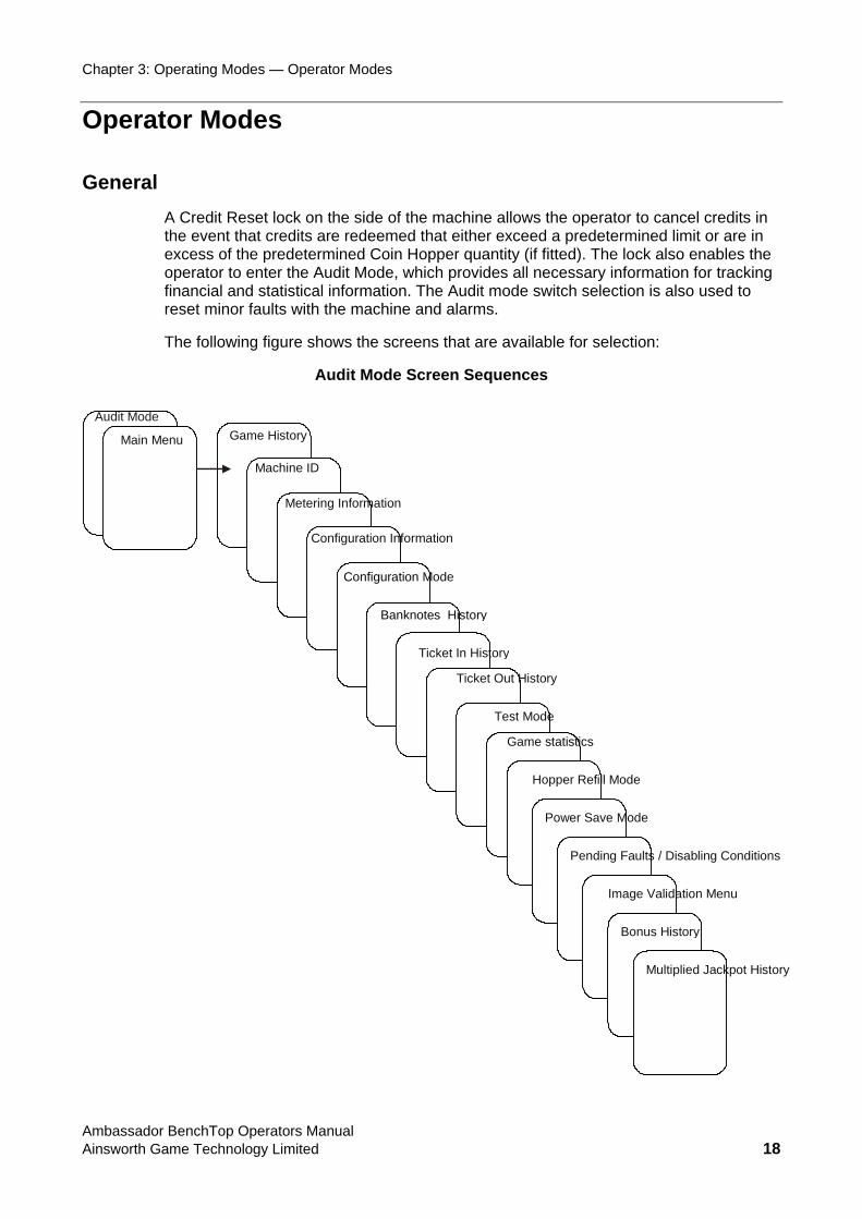
General A Credit Reset lock on the side of the machine allows the operator to cancel credits in the event that credits are redeemed that either exceed a predetermined limit or are in excess of the predetermined Coin Hopper quantity (if fitted). The lock also enables the operator to enter the Audit Mode, which provides all necessary information for tracking financial and statistical information. The Audit mode switch selection is also used to reset minor faults with the machine and alarms.
The following figure shows the screens that are available for selection:
Audit Mode Screen Sequences
Game History
Machine ID
Metering Information
Configuration Information
Configuration Mode
Banknotes History
Test Mode
Audit Mode Main Menu
Pending Faults / Disabling Conditions
Power Save Mode
Hopper Refill Mode
Game statistics
Ticket In History
Ticket Out History
Bonus History
Image Validation Menu
Multiplied Jackpot History
Ambassador BenchTop Operators Manual Ainsworth Game Technology Limited 18

Chapter 3: Operating Modes — Operator Modes
Cancel Credit To cancel all credits in the machine when the credits being redeemed are in excess of the predetermined hopper payout limit (if fitted), press COLLECT to enter Cancel Credit Mode. When this is done, rotate the Reset switch lock anti-clockwise (momentarily). Where Ticket Payouts are used, this also initiates Ticket Payouts.
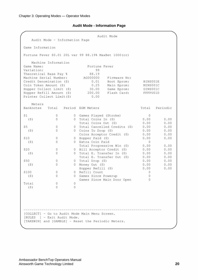
Audit The Audit Mode - Information Page displays a wide range of Machine Information relating to the particular configuration of the machine as well as some of the preset limits. The information is included at this screen for operator convenience and is repeated elsewhere in the various other modes.
To access the Audit Mode Information screen rotate the Audit Mode/Credit Reset switch clockwise to the Audit Mode position. This can only be done when the machine is in an “idle” state (i.e. no game in play) or if it is a Lockup condition.
By turning the key to the Reset position (anti-clockwise) errors that are not self-clearing can be cleared after the error condition itself has been addressed.
Note: The Audit Mode can be entered with credits in the machine.
Ambassador BenchTop Operators Manual Ainsworth Game Technology Limited 19
Chapter 3: Operating Modes — Operator Modes
Audit Mode - Information Page
Audit Mode Audit Mode - Information Page Game Information Fortune Fever $0.01 20L var 99 88.19% MaxBet 1000(cr) Machine Information Game Name: Fortune Fever Variation: 99 Theoretical Base Pay % 88.19 Machine Serial Number: AG000000 Firmware No: Credit Denomination ($) 0.01 Boot Eprom: BINS001E Coin Token Amount ($) 0.25 Main Eprom: MINS001C Hopper Collect Limit ($) 30.00 Game Eprom: GINS001C Hopper Refill Amount ($) 200.00 Flash Card: FFFPU01D Printer Collect Limit($) 0.00 Meters Banknotes Total Period EGM Meters Total Periodic $1 0 0 Games Played (Stroke) 0 ($) 0 0 Total Coins In ($) 0.00 0.00 Total Coins Out ($) 0.00 0.00$5 0 0 Total Cancelled Credits ($) 0.00 0.00 ($) 0 0 Coins To Drop ($) 0.00 0.00 Coins Acceptor Credit ($) 0.00 0.00$10 0 0 Hopper Paid ($) 0.00 0.00 ($) 0 0 Extra Coin Paid 0 Total Progressive Win ($) 0.00 0.00$20 0 0 Bill Acceptor Credit ($) 0.00 0.00 ($) 0 0 Total E. Transfer In ($) 0.00 0.00 Total E. Transfer Out ($) 0.00 0.00$50 0 0 Total Drop ($) 0.00 0.00 ($) 0 0 Money Out ($) 0.00 0.00 Hopper Refill ($) 0.00 0.00$100 0 0 Refill Count 0 ($) 0 0 Games Since Powerup 0 Games Since Main Door Open 0 Total 0 0 ($) 0 0 --------------------------------------------------------------------- [COLLECT] - Go to Audit Mode Main Menu Screen. [RULES ] - Exit Audit Mode. [TAKEWIN] and [GAMBLE] - Reset the Periodic Meters.
Ambassador BenchTop Operators Manual Ainsworth Game Technology Limited 20
Chapter 3: Operating Modes — Audit Mode
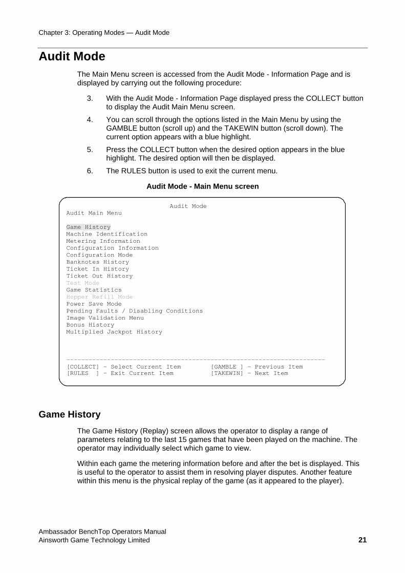
Audit Mode The Main Menu screen is accessed from the Audit Mode - Information Page and is displayed by carrying out the following procedure:
3. With the Audit Mode - Information Page displayed press the COLLECT button to display the Audit Main Menu screen.
4. You can scroll through the options listed in the Main Menu by using the GAMBLE button (scroll up) and the TAKEWIN button (scroll down). The current option appears with a blue highlight.
5. Press the COLLECT button when the desired option appears in the blue highlight. The desired option will then be displayed.
6. The RULES button is used to exit the current menu.
Audit Mode - Main Menu screen
Audit Mode Audit Main Menu Game History Machine Identification Metering Information Configuration Information Configuration Mode Banknotes History Ticket In History Ticket Out History Test Mode Game Statistics Hopper Refill Mode Power Save Mode Pending Faults / Disabling Conditions Image Validation Menu Bonus History Multiplied Jackpot History ---------------------------------------------------------------------- [COLLECT] – Select Current Item [GAMBLE ] – Previous Item [RULES ] – Exit Current Item [TAKEWIN] – Next Item
Game History The Game History (Replay) screen allows the operator to display a range of parameters relating to the last 15 games that have been played on the machine. The operator may individually select which game to view.
Within each game the metering information before and after the bet is displayed. This is useful to the operator to assist them in resolving player disputes. Another feature within this menu is the physical replay of the game (as it appeared to the player).
Ambassador BenchTop Operators Manual Ainsworth Game Technology Limited 21

Chapter 3: Operating Modes — Audit Mode
The individual Game History parameters can be displayed by carrying out the following procedure:
1. Highlight the Game History option in the Audit Mode Main Menu by scrolling through the options with the GAMBLE (scroll up) and TAKEWIN (scroll down) buttons. The selected option appears with a blue highlight.
2. Press the COLLECT button to enter the Game History screen.
3. With the Game History Replay screen displayed the most recent game parameters are displayed (numbered 1) and the oldest game is numbered 15. To view parameters of other games played press the TAKEWIN (select next game) or GAMBLE (selects the previous game) buttons.
4. Press the COLLECT button to display a replay of the game as it appeared to the player.
Where a “Free-Spin” has occurred within the game being replayed the additional free-spins can be viewed individually by pressing COLLECT. Subsequent presses of the COLLECT button will advance through the individual “Free-Spin” games. All Free-Spins must be replayed before you can exit this screen.
During game replay, press the RULES button to display the Rules screen.
5. Once the game has been replayed (including Free-Spins) press GAMBLE to return to the Game History Replay screen.
6. Press the RULES button to return to the Audit Mode Main Menu screen.
7. Press the RULES button twice and you will exit firstly to the initial Audit Modes – Information Page and then right out of Audit mode to the normal game screen (ready to be played).
Ambassador BenchTop Operators Manual Ainsworth Game Technology Limited 22
Chapter 3: Operating Modes — Audit Mode
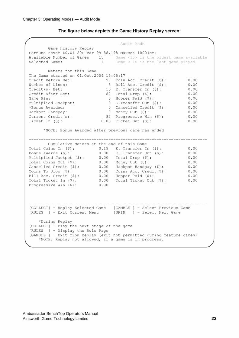
The figure below depicts the Game History Replay screen:
Audit Mode Game History Replay Fortune Fever $0.01 20L var 99 88.19% MaxBet 1000(cr) Available Number of Games 15 Game <15> is the oldest game available Selected Game: 1 Game < 1> is the last game played Meters for this Game The Game started on 01,Oct,2004 15:05:17 Credit Before Bet: 97 Coin Acc. Credit ($): 0.00 Number of Lines: 3 Bill Acc. Credit ($): 0.00 Credit(s) Bet: 15 E. Transfer In ($): 0.00 Credit After Bet: 82 Total Drop ($): 0.00 Game Win: 0 Hopper Paid ($): 0.00 Multiplied Jackpot: 0 E.Transfer Out ($): 0.00 *Bonus Awarded: 0 Cancelled Credit ($): 0.00 Jackpot Handpay: 0 Money Out ($): 0.00 Current Credit(s): 82 Progressive Win ($): 0.00 Ticket In ($): 0.00 Ticket Out ($): 0.00
*NOTE: Bonus Awarded after previous game has ended -------------------------------------------------------------------------- Cumulative Meters at the end of this Game Total Coins In ($): 0.18 E. Transfer In ($): 0.00 Bonus Awards ($): 0.00 E. Transfer Out ($): 0.00 Multiplied Jackpot ($): 0.00 Total Drop ($): 0.00 Total Coins Out ($): 0.00 Money Out ($): 0.00 Cancelled Credit ($): 0.00 Jackpot Handpay ($): 0.00 Coins To Drop ($): 0.00 Coins Acc. Credit($): 0.00 Bill Acc. Credit ($): 0.00 Hopper Paid ($): 0.00 Total Ticket In ($): 0.00 Total Ticket Out ($): 0.00 Progressive Win ($): 0.00 -------------------------------------------------------------------------- [COLLECT] – Replay Selected Game [GAMBLE ] – Select Previous Game [RULES ] - Exit Current Menu [SPIN ] – Select Next Game *During Replay [COLLECT] – Play the next stage of the game [RULES ] – Display the Rule Page [GAMBLE ] – Exit from replay (exit not permitted during feature games) *NOTE: Replay not allowed, if a game is in progress.
Ambassador BenchTop Operators Manual Ainsworth Game Technology Limited 23
Chapter 3: Operating Modes — Audit Mode
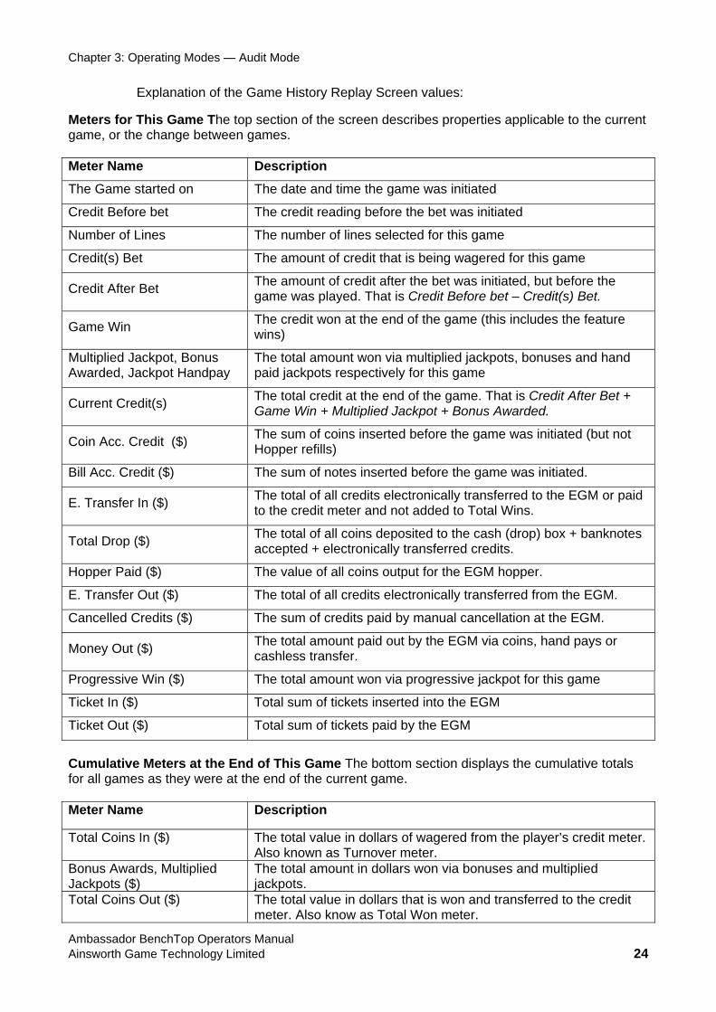
Explanation of the Game History Replay Screen values:
Meters for This Game The top section of the screen describes properties applicable to the current game, or the change between games. Meter Name Description
The Game started on The date and time the game was initiated
Credit Before bet The credit reading before the bet was initiated
Number of Lines The number of lines selected for this game
Credit(s) Bet The amount of credit that is being wagered for this game
Credit After Bet The amount of credit after the bet was initiated, but before the game was played. That is Credit Before bet – Credit(s) Bet.
Game Win The credit won at the end of the game (this includes the feature wins)
Multiplied Jackpot, Bonus Awarded, Jackpot Handpay
The total amount won via multiplied jackpots, bonuses and hand paid jackpots respectively for this game
Current Credit(s) The total credit at the end of the game. That is Credit After Bet + Game Win + Multiplied Jackpot + Bonus Awarded.
Coin Acc. Credit ($) The sum of coins inserted before the game was initiated (but not Hopper refills)
Bill Acc. Credit ($) The sum of notes inserted before the game was initiated.
E. Transfer In ($) The total of all credits electronically transferred to the EGM or paid to the credit meter and not added to Total Wins.
Total Drop ($) The total of all coins deposited to the cash (drop) box + banknotes accepted + electronically transferred credits.
Hopper Paid ($) The value of all coins output for the EGM hopper.
E. Transfer Out ($) The total of all credits electronically transferred from the EGM.
Cancelled Credits ($) The sum of credits paid by manual cancellation at the EGM.
Money Out ($) The total amount paid out by the EGM via coins, hand pays or cashless transfer.
Progressive Win ($) The total amount won via progressive jackpot for this game
Ticket In ($) Total sum of tickets inserted into the EGM
Ticket Out ($) Total sum of tickets paid by the EGM
Cumulative Meters at the End of This Game The bottom section displays the cumulative totals for all games as they were at the end of the current game. Meter Name Description
Total Coins In ($) The total value in dollars of wagered from the player’s credit meter. Also known as Turnover meter.
Bonus Awards, Multiplied Jackpots ($)
The total amount in dollars won via bonuses and multiplied jackpots.
Total Coins Out ($) The total value in dollars that is won and transferred to the credit meter. Also know as Total Won meter.
Ambassador BenchTop Operators Manual Ainsworth Game Technology Limited 24
Chapter 3: Operating Modes — Audit Mode
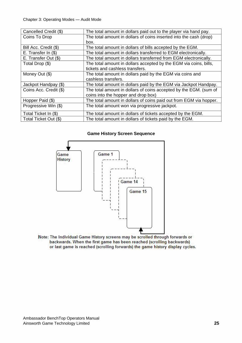
Cancelled Credit ($) The total amount in dollars paid out to the player via hand pay. Coins To Drop The total amount in dollars of coins inserted into the cash (drop)
box. Bill Acc. Credit ($) The total amount in dollars of bills accepted by the EGM. E. Transfer In ($) The total amount in dollars transferred to EGM electronically. E. Transfer Out ($) The total amount in dollars transferred from EGM electronically. Total Drop ($) The total amount in dollars accepted by the EGM via coins, bills,
tickets and cashless transfers. Money Out ($) The total amount in dollars paid by the EGM via coins and
cashless transfers. Jackpot Handpay ($) The total amount in dollars paid by the EGM via Jackpot Handpay. Coins Acc. Credit ($) The total amount in dollars of coins accepted by the EGM. (sum of
coins into the hopper and drop box) Hopper Paid ($) The total amount in dollars of coins paid out from EGM via hopper. Progressive Win ($) The total amount won via progressive jackpot.
Total Ticket In ($) The total amount in dollars of tickets accepted by the EGM. Total Ticket Out ($) The total amount in dollars of tickets paid by the EGM.
Game History Screen Sequence
Ambassador BenchTop Operators Manual Ainsworth Game Technology Limited 25
Chapter 3: Operating Modes — Audit Mode
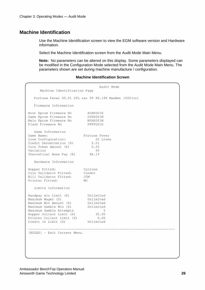
Machine Identification Use the Machine Identification screen to view the EGM software version and Hardware information.
Select the Machine Identification screen from the Audit Mode Main Menu.
Note: No parameters can be altered on this display. Some parameters displayed can be modified in the Configuration Mode selected from the Audit Mode Main Menu. The parameters shown are set during machine manufacture / configuration.
Machine Identification Screen
Audit Mode Machine Identification Page Fortune Fever $0.01 20L var 99 88.19% MaxBet 1000(cr) Firmware Information Boot Eprom Firmware No BINS001E Game Eprom Firmware No GINS001M Main Eprom Firmware No MINS001M Flash Firmware No FFFPU01D Game Information Game Name: Fortune Fever Line Configuration: 20 Lines Credit Denomination ($) 0.01 Coin Token Amount ($) 0.25 Variation 99 Theoretical Base Pay (%) 88.19 Hardware Information Hopper Fitted: Cyclone Coin Validator Fitted: Condor Bill Validator Fitted: JCM Printer Fitted: NO Limits Information Handpay win Limit ($) Unlimited Maximum Wager ($) Unlimited Maximum Win Amount ($) Unlimited Maximum Gamble Win ($) Unlimited Maximum Gamble Attempts 5 Hopper Collect Limit ($) 30.00 Printer Collect Limit ($) 0.00 Credit In Limit ($) Unlimited -------------------------------------------------------------------------- [RULES] - Exit Current Menu.
Ambassador BenchTop Operators Manual Ainsworth Game Technology Limited 26
Chapter 3: Operating Modes — Audit Mode
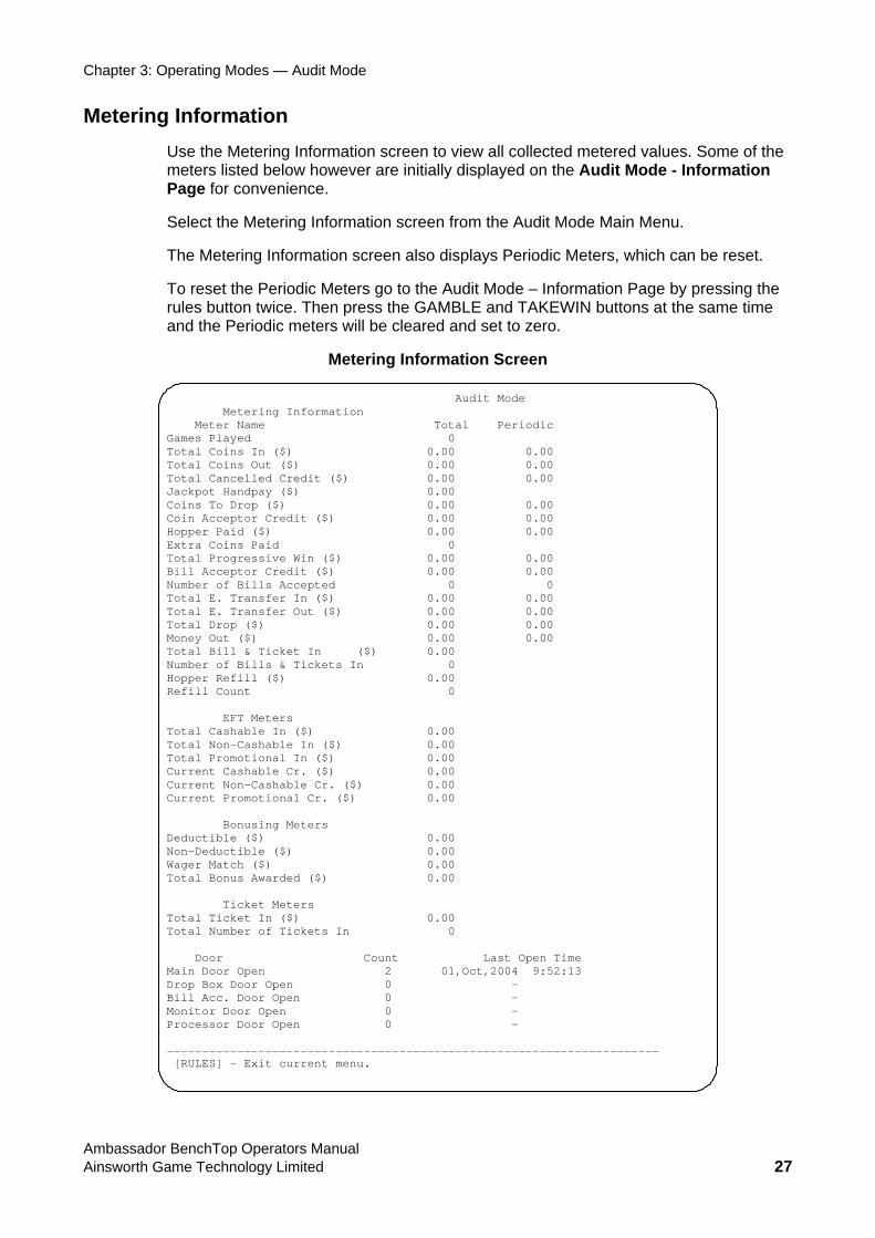
Metering Information Use the Metering Information screen to view all collected metered values. Some of the meters listed below however are initially displayed on the Audit Mode - Information Page for convenience.
Select the Metering Information screen from the Audit Mode Main Menu.
The Metering Information screen also displays Periodic Meters, which can be reset.
To reset the Periodic Meters go to the Audit Mode – Information Page by pressing the rules button twice. Then press the GAMBLE and TAKEWIN buttons at the same time and the Periodic meters will be cleared and set to zero.
Metering Information Screen
Audit Mode Metering Information Meter Name Total Periodic Games Played 0 Total Coins In ($) 0.00 0.00 Total Coins Out ($) 0.00 0.00 Total Cancelled Credit ($) 0.00 0.00 Jackpot Handpay ($) 0.00 Coins To Drop ($) 0.00 0.00 Coin Acceptor Credit ($) 0.00 0.00 Hopper Paid ($) 0.00 0.00 Extra Coins Paid 0 Total Progressive Win ($) 0.00 0.00 Bill Acceptor Credit ($) 0.00 0.00 Number of Bills Accepted 0 0 Total E. Transfer In ($) 0.00 0.00 Total E. Transfer Out ($) 0.00 0.00 Total Drop ($) 0.00 0.00 Money Out ($) 0.00 0.00 Total Bill & Ticket In ($) 0.00 Number of Bills & Tickets In 0 Hopper Refill ($) 0.00 Refill Count 0 EFT Meters Total Cashable In ($) 0.00 Total Non-Cashable In ($) 0.00 Total Promotional In ($) 0.00 Current Cashable Cr. ($) 0.00 Current Non-Cashable Cr. ($) 0.00 Current Promotional Cr. ($) 0.00 Bonusing Meters Deductible ($) 0.00 Non-Deductible ($) 0.00 Wager Match ($) 0.00 Total Bonus Awarded ($) 0.00 Ticket Meters Total Ticket In ($) 0.00 Total Number of Tickets In 0 Door Count Last Open Time Main Door Open 2 01,Oct,2004 9:52:13 Drop Box Door Open 0 - Bill Acc. Door Open 0 - Monitor Door Open 0 - Processor Door Open 0 - ---------------------------------------------------------------------- [RULES] - Exit current menu.
Ambassador BenchTop Operators Manual Ainsworth Game Technology Limited 27
Chapter 3: Operating Modes — Audit Mode
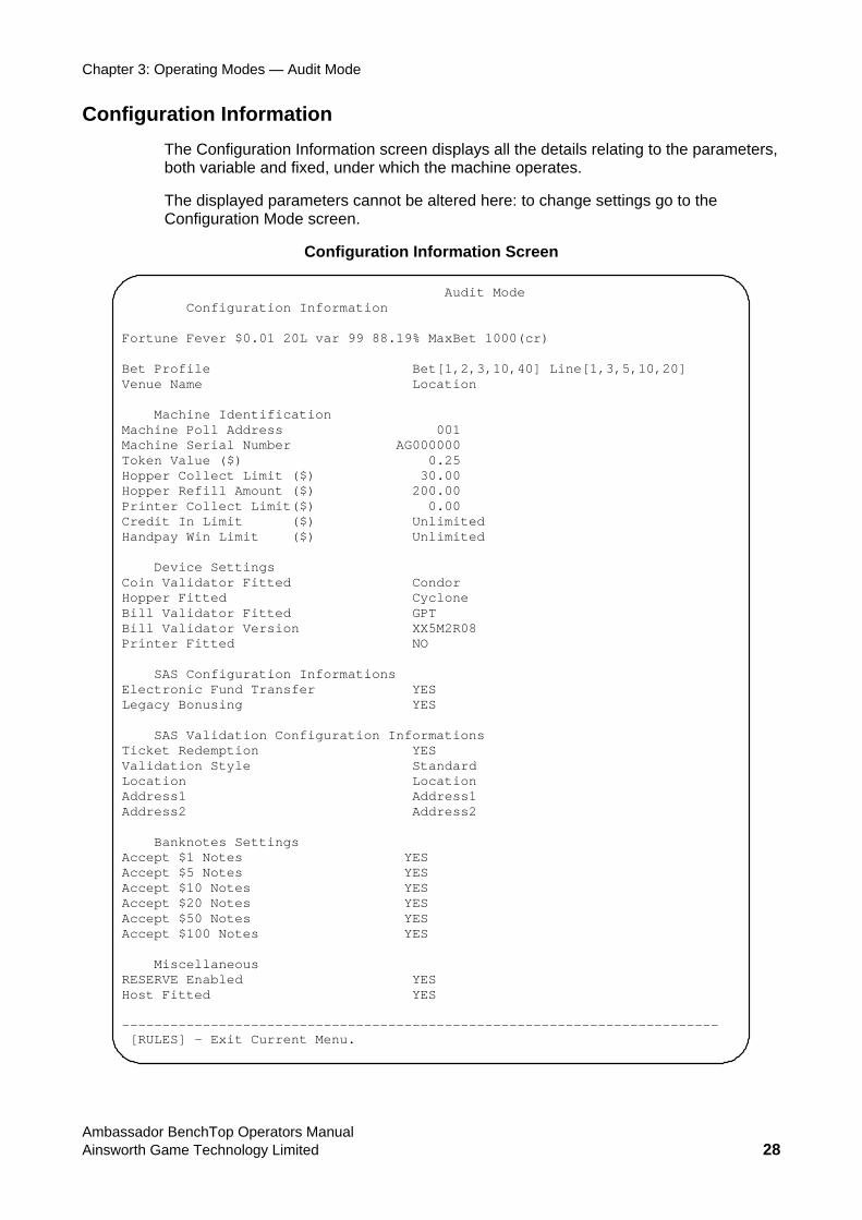
Configuration Information The Configuration Information screen displays all the details relating to the parameters, both variable and fixed, under which the machine operates.
The displayed parameters cannot be altered here: to change settings go to the Configuration Mode screen.
Configuration Information Screen
Audit Mode Configuration Information Fortune Fever $0.01 20L var 99 88.19% MaxBet 1000(cr) Bet Profile Bet[1,2,3,10,40] Line[1,3,5,10,20] Venue Name Location Machine Identification Machine Poll Address 001 Machine Serial Number AG000000 Token Value ($) 0.25 Hopper Collect Limit ($) 30.00 Hopper Refill Amount ($) 200.00 Printer Collect Limit($) 0.00 Credit In Limit ($) Unlimited Handpay Win Limit ($) Unlimited Device Settings Coin Validator Fitted Condor Hopper Fitted Cyclone Bill Validator Fitted GPT Bill Validator Version XX5M2R08 Printer Fitted NO SAS Configuration Informations Electronic Fund Transfer YES Legacy Bonusing YES SAS Validation Configuration Informations Ticket Redemption YES Validation Style Standard Location Location Address1 Address1 Address2 Address2 Banknotes Settings Accept $1 Notes YES Accept $5 Notes YES Accept $10 Notes YES Accept $20 Notes YES Accept $50 Notes YES Accept $100 Notes YES Miscellaneous RESERVE Enabled YES Host Fitted YES -------------------------------------------------------------------------- [RULES] - Exit Current Menu.
Ambassador BenchTop Operators Manual Ainsworth Game Technology Limited 28
Chapter 3: Operating Modes — Audit Mode
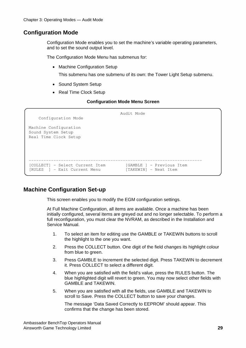
Configuration Mode Configuration Mode enables you to set the machine’s variable operating parameters, and to set the sound output level.
The Configuration Mode Menu has submenus for:
• Machine Configuration Setup
This submenu has one submenu of its own: the Tower Light Setup submenu.
• Sound System Setup
• Real Time Clock Setup
Configuration Mode Menu Screen
Audit Mode Configuration Mode Machine Configuration Sound System Setup Real Time Clock Setup ---------------------------------------------------------------------- [COLLECT] – Select Current Item [GAMBLE ] – Previous Item [RULES ] - Exit Current Menu [TAKEWIN] – Next Item
Machine Configuration Set-up This screen enables you to modify the EGM configuration settings.
At Full Machine Configuration, all items are available. Once a machine has been initially configured, several items are greyed out and no longer selectable. To perform a full reconfiguration, you must clear the NVRAM, as described in the Installation and Service Manual.
1. To select an item for editing use the GAMBLE or TAKEWIN buttons to scroll the highlight to the one you want.
2. Press the COLLECT button. One digit of the field changes its highlight colour from blue to green.
3. Press GAMBLE to increment the selected digit. Press TAKEWIN to decrement it. Press COLLECT to select a different digit.
4. When you are satisfied with the field’s value, press the RULES button. The blue highlighted digit will revert to green. You may now select other fields with GAMBLE and TAKEWIN.
5. When you are satisfied with all the fields, use GAMBLE and TAKEWIN to scroll to Save. Press the COLLECT button to save your changes.
The message ‘Data Saved Correctly to EEPROM’ should appear. This confirms that the change has been stored.
Ambassador BenchTop Operators Manual Ainsworth Game Technology Limited 29
Chapter 3: Operating Modes — Audit Mode
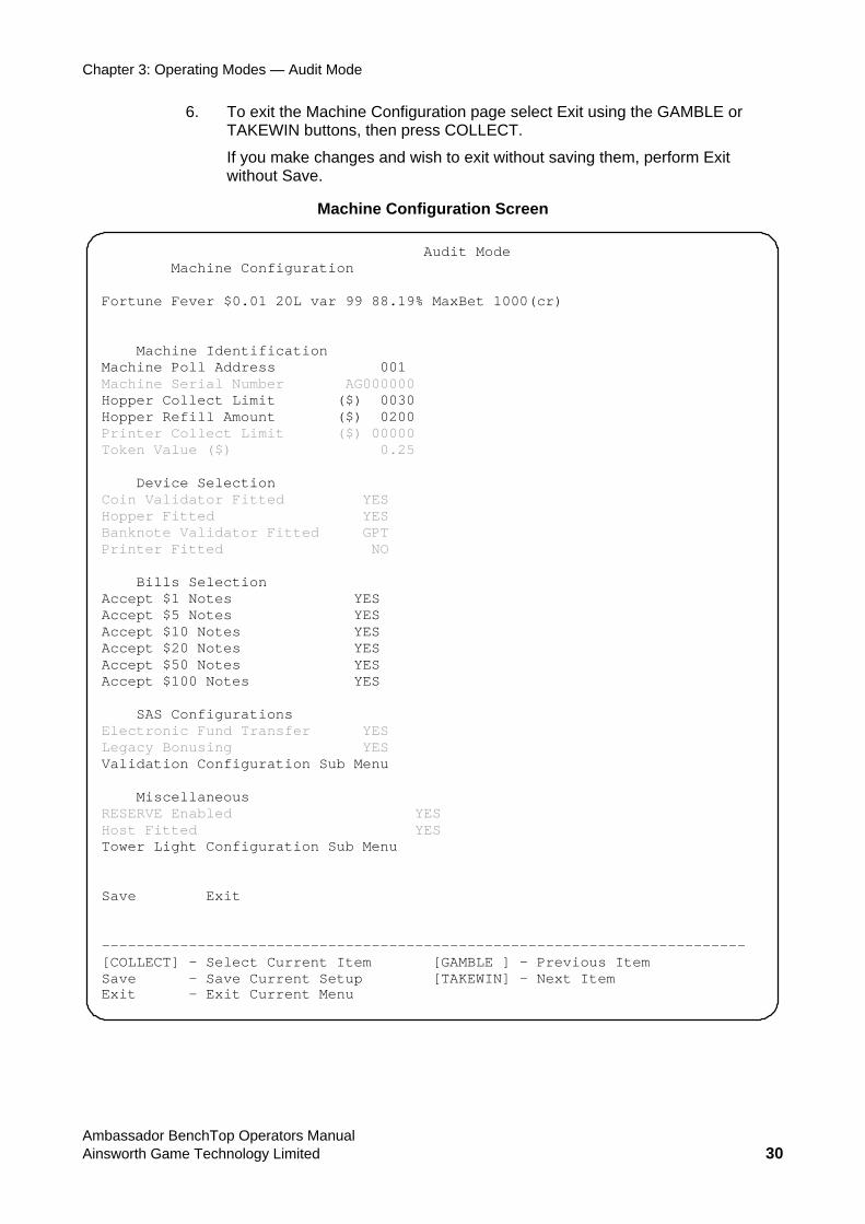
6. To exit the Machine Configuration page select Exit using the GAMBLE or TAKEWIN buttons, then press COLLECT.
If you make changes and wish to exit without saving them, perform Exit without Save.
Machine Configuration Screen
Audit Mode Machine Configuration Fortune Fever $0.01 20L var 99 88.19% MaxBet 1000(cr) Machine Identification Machine Poll Address 001 Machine Serial Number AG000000 Hopper Collect Limit ($) 0030 Hopper Refill Amount ($) 0200 Printer Collect Limit ($) 00000 Token Value ($) 0.25 Device Selection Coin Validator Fitted YES Hopper Fitted YES Banknote Validator Fitted GPT Printer Fitted NO Bills Selection Accept $1 Notes YES Accept $5 Notes YES Accept $10 Notes YES Accept $20 Notes YES Accept $50 Notes YES Accept $100 Notes YES SAS Configurations Electronic Fund Transfer YES Legacy Bonusing YES Validation Configuration Sub Menu Miscellaneous RESERVE Enabled YES Host Fitted YES Tower Light Configuration Sub Menu Save Exit -------------------------------------------------------------------------- [COLLECT] – Select Current Item [GAMBLE ] – Previous Item Save - Save Current Setup [TAKEWIN] – Next Item Exit - Exit Current Menu
Ambassador BenchTop Operators Manual Ainsworth Game Technology Limited 30
Chapter 3: Operating Modes — Audit Mode
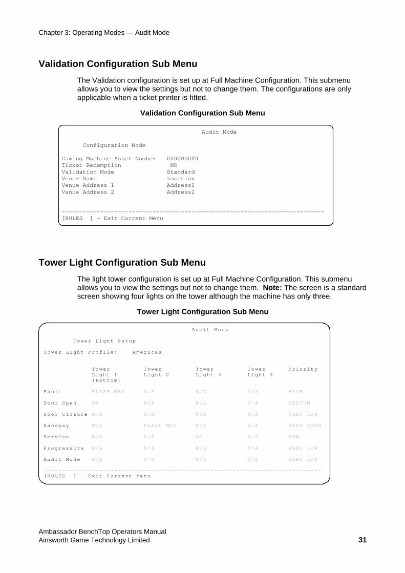
Validation Configuration Sub Menu The Validation configuration is set up at Full Machine Configuration. This submenu allows you to view the settings but not to change them. The configurations are only applicable when a ticket printer is fitted.
Validation Configuration Sub Menu
Audit Mode
Configuration Mode Gaming Machine Asset Number 000000000 Ticket Redemption NO Validation Mode Standard Venue Name Location Venue Address 1 Address1 Venue Address 2 Address2 --------------------------------------------------------------------------- [RULES ] - Exit Current Menu
Tower Light Configuration Sub Menu The light tower configuration is set up at Full Machine Configuration. This submenu allows you to view the settings but not to change them. Note: The screen is a standard screen showing four lights on the tower although the machine has only three.
Tower Light Configuration Sub Menu
Audit Mode Tower Light Setup Tower Light Profile: Americas Tower Tower Tower Tower Priority Light 1 Light 2 Light 3 Light 4 (Bottom) Fault FLASH MED N/A N/A N/A HIGH Door Open ON N/A N/A N/A MEDIUM Door Closure N/A N/A N/A N/A VERY LOW Handpay N/A FLASH MED N/A N/A VERY HIGH Service N/A N/A ON N/A LOW Progressive N/A N/A N/A N/A VERY LOW Audit Mode N/A N/A N/A N/A VERY LOW --------------------------------------------------------------------------- [RULES ] - Exit Current Menu
Ambassador BenchTop Operators Manual Ainsworth Game Technology Limited 31
Chapter 3: Operating Modes — Audit Mode
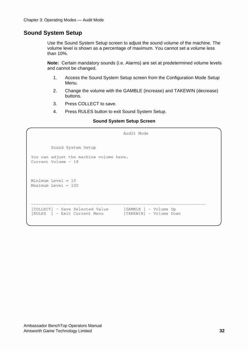
Sound System Setup Use the Sound System Setup screen to adjust the sound volume of the machine. The volume level is shown as a percentage of maximum. You cannot set a volume less than 10%.
Note: Certain mandatory sounds (i.e. Alarms) are set at predetermined volume levels and cannot be changed.
1. Access the Sound System Setup screen from the Configuration Mode Setup Menu.
2. Change the volume with the GAMBLE (increase) and TAKEWIN (decrease) buttons.
3. Press COLLECT to save.
4. Press RULES button to exit Sound System Setup.
Sound System Setup Screen
Audit Mode Sound System Setup You can adjust the machine volume here. Current Volume – 18 Minimum Level = 10 Maximum Level = 100 ---------------------------------------------------------------------- [COLLECT] – Save Selected Value [GAMBLE ] – Volume Up [RULES ] - Exit Current Menu [TAKEWIN] – Volume Down
Ambassador BenchTop Operators Manual Ainsworth Game Technology Limited 32
Chapter 3: Operating Modes — Audit Mode
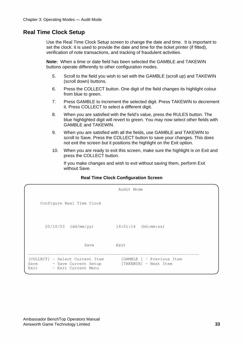
Real Time Clock Setup Use the Real Time Clock Setup screen to change the date and time. It is important to set the clock: it is used to provide the date and time for the ticket printer (if fitted), verification of note transactions, and tracking of fraudulent activities.
Note: When a time or date field has been selected the GAMBLE and TAKEWIN buttons operate differently to other configuration modes.
5. Scroll to the field you wish to set with the GAMBLE (scroll up) and TAKEWIN (scroll down) buttons.
6. Press the COLLECT button. One digit of the field changes its highlight colour from blue to green.
7. Press GAMBLE to increment the selected digit. Press TAKEWIN to decrement it. Press COLLECT to select a different digit.
8. When you are satisfied with the field’s value, press the RULES button. The blue highlighted digit will revert to green. You may now select other fields with GAMBLE and TAKEWIN.
9. When you are satisfied with all the fields, use GAMBLE and TAKEWIN to scroll to Save. Press the COLLECT button to save your changes. This does not exit the screen but it positions the highlight on the Exit option.
10. When you are ready to exit this screen, make sure the highlight is on Exit and press the COLLECT button.
If you make changes and wish to exit without saving them, perform Exit without Save.
Real Time Clock Configuration Screen
Audit Mode Configure Real Time Clock 20/10/03 (dd/mm/yy) 16:01:14 (hh:mm:ss) Save Exit ---------------------------------------------------------------------- [COLLECT] – Select Current Item [GAMBLE ] – Previous Item Save - Save Current Setup [TAKEWIN] – Next Item Exit - Exit Current Menu
Ambassador BenchTop Operators Manual Ainsworth Game Technology Limited 33
Chapter 3: Operating Modes — Audit Mode
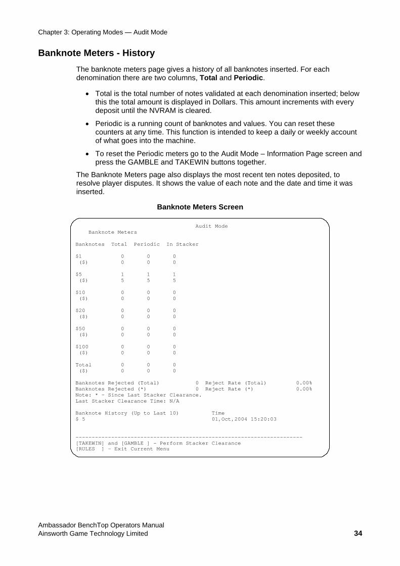
Banknote Meters - History The banknote meters page gives a history of all banknotes inserted. For each denomination there are two columns, Total and Periodic.
• Total is the total number of notes validated at each denomination inserted; below this the total amount is displayed in Dollars. This amount increments with every deposit until the NVRAM is cleared.
• Periodic is a running count of banknotes and values. You can reset these counters at any time. This function is intended to keep a daily or weekly account of what goes into the machine.
• To reset the Periodic meters go to the Audit Mode – Information Page screen and press the GAMBLE and TAKEWIN buttons together.
The Banknote Meters page also displays the most recent ten notes deposited, to resolve player disputes. It shows the value of each note and the date and time it was inserted.
Banknote Meters Screen
Audit Mode Banknote Meters Banknotes Total Periodic In Stacker $1 0 0 0 ($) 0 0 0 $5 1 1 1 ($) 5 5 5 $10 0 0 0 ($) 0 0 0 $20 0 0 0 ($) 0 0 0 $50 0 0 0 ($) 0 0 0 $100 0 0 0 ($) 0 0 0 Total 0 0 0 ($) 0 0 0 Banknotes Rejected (Total) 0 Reject Rate (Total) 0.00% Banknotes Rejected (*) 0 Reject Rate (*) 0.00% Note: * - Since Last Stacker Clearance. Last Stacker Clearance Time: N/A Banknote History (Up to Last 10) Time $ 5 01,Oct,2004 15:20:03 ---------------------------------------------------------------------- [TAKEWIN] and [GAMBLE ] – Perform Stacker Clearance [RULES ] - Exit Current Menu
Ambassador BenchTop Operators Manual Ainsworth Game Technology Limited 34
Chapter 3: Operating Modes — Audit Mode
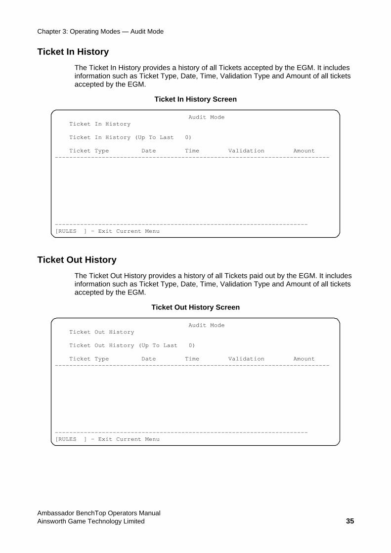
Ticket In History The Ticket In History provides a history of all Tickets accepted by the EGM. It includes information such as Ticket Type, Date, Time, Validation Type and Amount of all tickets accepted by the EGM.
Ticket In History Screen
Audit Mode Ticket In History Ticket In History (Up To Last 0) Ticket Type Date Time Validation Amount ---------------------------------------------------------------------------- ---------------------------------------------------------------------- [RULES ] - Exit Current Menu
Ticket Out History The Ticket Out History provides a history of all Tickets paid out by the EGM. It includes information such as Ticket Type, Date, Time, Validation Type and Amount of all tickets accepted by the EGM.
Ticket Out History Screen
Audit Mode Ticket Out History Ticket Out History (Up To Last 0) Ticket Type Date Time Validation Amount ---------------------------------------------------------------------------- ---------------------------------------------------------------------- [RULES ] - Exit Current Menu
Ambassador BenchTop Operators Manual Ainsworth Game Technology Limited 35
Chapter 3: Operating Modes — Audit Mode
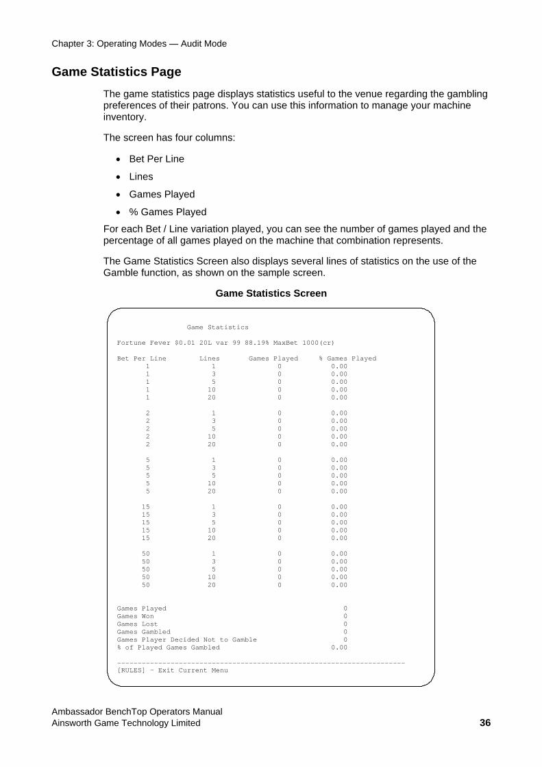
Game Statistics Page The game statistics page displays statistics useful to the venue regarding the gambling preferences of their patrons. You can use this information to manage your machine inventory.
The screen has four columns:
• Bet Per Line
• Lines
• Games Played
• % Games Played
For each Bet / Line variation played, you can see the number of games played and the percentage of all games played on the machine that combination represents.
The Game Statistics Screen also displays several lines of statistics on the use of the Gamble function, as shown on the sample screen.
Game Statistics Screen
Game Statistics Fortune Fever $0.01 20L var 99 88.19% MaxBet 1000(cr) Bet Per Line Lines Games Played % Games Played 1 1 0 0.00 1 3 0 0.00 1 5 0 0.00 1 10 0 0.00 1 20 0 0.00 2 1 0 0.00 2 3 0 0.00 2 5 0 0.00 2 10 0 0.00 2 20 0 0.00 5 1 0 0.00 5 3 0 0.00 5 5 0 0.00 5 10 0 0.00 5 20 0 0.00 15 1 0 0.00 15 3 0 0.00 15 5 0 0.00 15 10 0 0.00 15 20 0 0.00 50 1 0 0.00 50 3 0 0.00 50 5 0 0.00 50 10 0 0.00 50 20 0 0.00 Games Played 0 Games Won 0 Games Lost 0 Games Gambled 0 Games Player Decided Not to Gamble 0 % of Played Games Gambled 0.00 ---------------------------------------------------------------------- [RULES] - Exit Current Menu
Ambassador BenchTop Operators Manual Ainsworth Game Technology Limited 36
Chapter 3: Operating Modes — Audit Mode
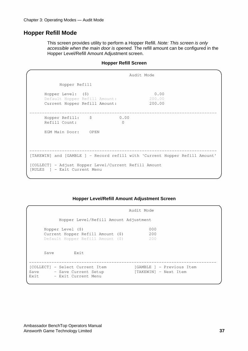
Hopper Refill Mode This screen provides utility to perform a Hopper Refill. Note: This screen is only accessible when the main door is opened. The refill amount can be configured in the Hopper Level/Refill Amount Adjustment screen.
Hopper Refill Screen
Audit Mode Hopper Refill
Hopper Level: ($) 0.00 Default Hopper Refill Amount: 200.00 Current Hopper Refill Amount: 200.00
--------------------------------------------------------------------------- Hopper Refill: $ 0.00
Refill Count: 0 EGM Main Door: OPEN
--------------------------------------------------------------------------- [TAKEWIN] and [GAMBLE ] – Record refill with ‘Current Hopper Refill Amount’ [COLLECT] – Adjust Hopper Level/Current Refill Amount [RULES ] - Exit Current Menu
Hopper Level/Refill Amount Adjustment Screen
Audit Mode Hopper Level/Refill Amount Adjustment Hopper Level ($) 000 Current Hopper Refill Amount ($) 200 Default Hopper Refill Amount ($) 200 Save Exit --------------------------------------------------------------------------- [COLLECT] – Select Current Item [GAMBLE ] – Previous Item Save – Save Current Setup [TAKEWIN] – Next Item Exit - Exit Current Menu
Ambassador BenchTop Operators Manual Ainsworth Game Technology Limited 37
Chapter 3: Operating Modes — Audit Mode
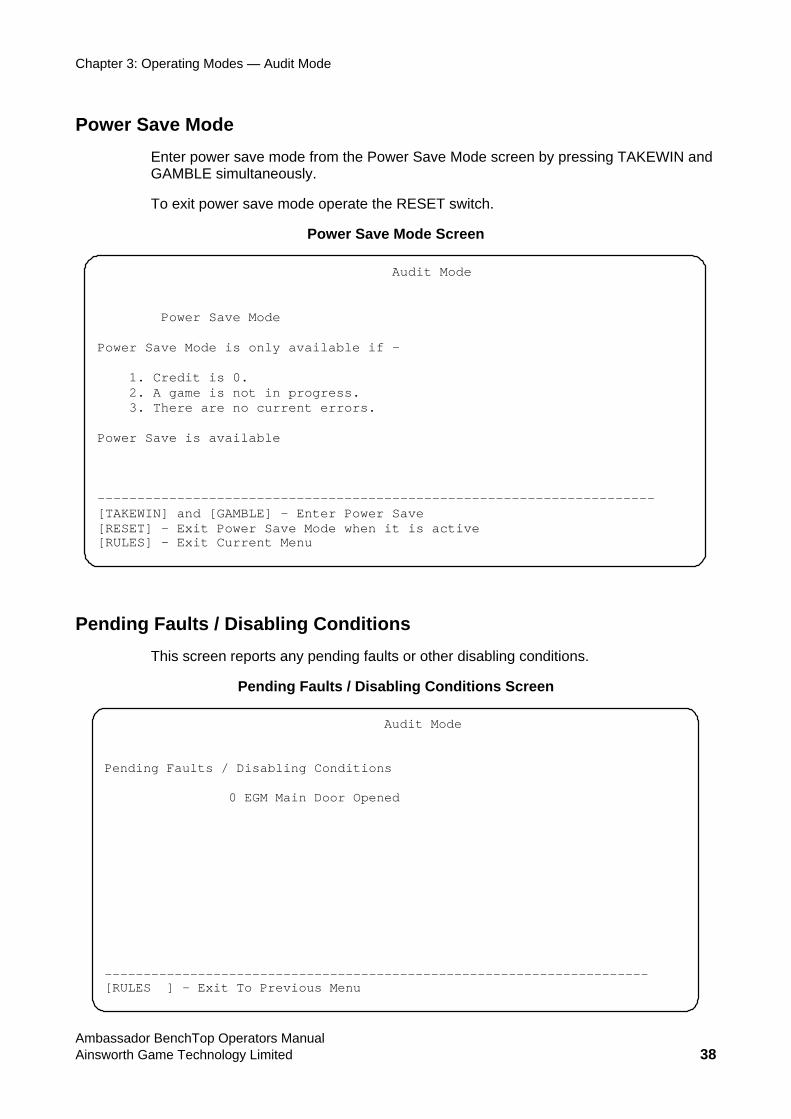
Power Save Mode Enter power save mode from the Power Save Mode screen by pressing TAKEWIN and GAMBLE simultaneously.
To exit power save mode operate the RESET switch.
Power Save Mode Screen
Audit Mode Power Save Mode Power Save Mode is only available if - 1. Credit is 0. 2. A game is not in progress. 3. There are no current errors. Power Save is available ---------------------------------------------------------------------- [TAKEWIN] and [GAMBLE] – Enter Power Save [RESET] - Exit Power Save Mode when it is active [RULES] - Exit Current Menu
Pending Faults / Disabling Conditions This screen reports any pending faults or other disabling conditions.
Pending Faults / Disabling Conditions Screen
Audit Mode Pending Faults / Disabling Conditions 0 EGM Main Door Opened ---------------------------------------------------------------------- [RULES ] - Exit To Previous Menu
Ambassador BenchTop Operators Manual Ainsworth Game Technology Limited 38
Chapter 3: Operating Modes — Audit Mode
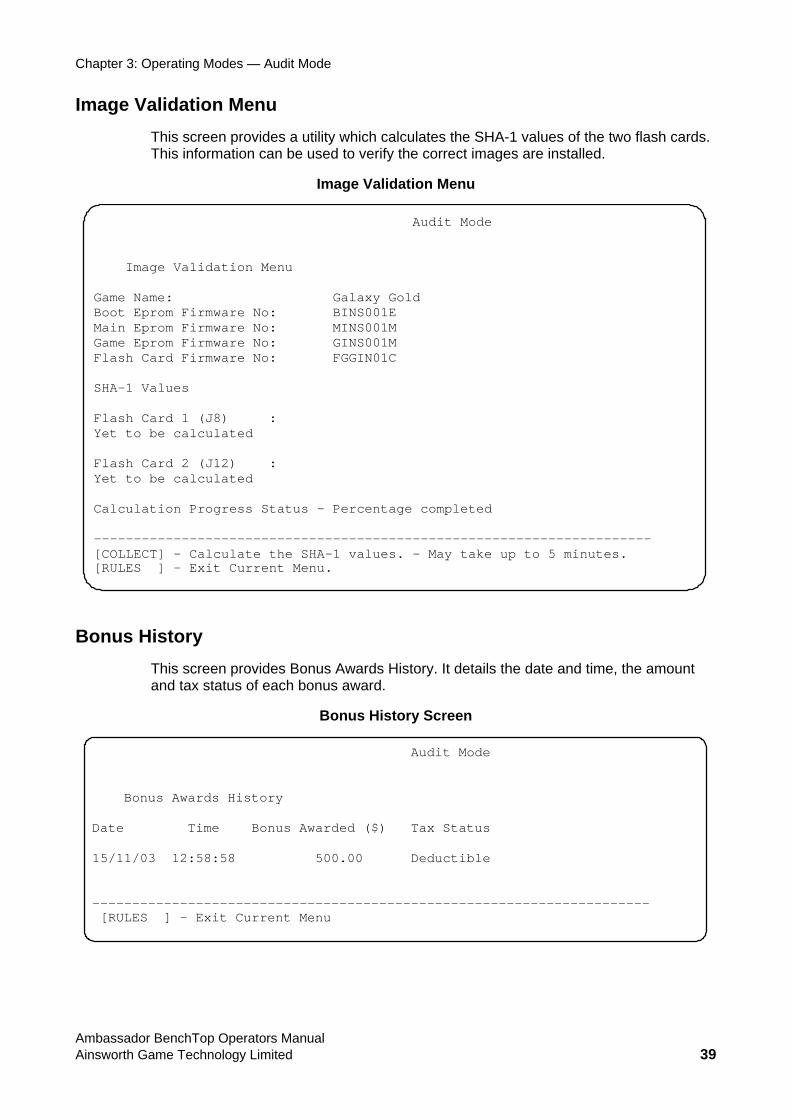
Image Validation Menu This screen provides a utility which calculates the SHA-1 values of the two flash cards. This information can be used to verify the correct images are installed.
Image Validation Menu
Audit Mode Image Validation Menu Game Name: Galaxy Gold Boot Eprom Firmware No: BINS001E Main Eprom Firmware No: MINS001M Game Eprom Firmware No: GINS001M Flash Card Firmware No: FGGIN01C SHA-1 Values Flash Card 1 (J8) : Yet to be calculated Flash Card 2 (J12) : Yet to be calculated Calculation Progress Status – Percentage completed ---------------------------------------------------------------------- [COLLECT] – Calculate the SHA-1 values. – May take up to 5 minutes. [RULES ] - Exit Current Menu.
Bonus History This screen provides Bonus Awards History. It details the date and time, the amount and tax status of each bonus award.
Bonus History Screen
Audit Mode Bonus Awards History Date Time Bonus Awarded ($) Tax Status 15/11/03 12:58:58 500.00 Deductible ---------------------------------------------------------------------- [RULES ] - Exit Current Menu
Ambassador BenchTop Operators Manual Ainsworth Game Technology Limited 39
Chapter 3: Operating Modes — Audit Mode
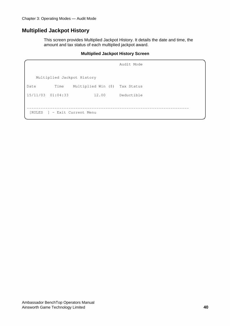
Multiplied Jackpot History This screen provides Multiplied Jackpot History. It details the date and time, the amount and tax status of each multiplied jackpot award.
Multiplied Jackpot History Screen
Audit Mode Multiplied Jackpot History Date Time Multiplied Win ($) Tax Status 15/11/03 01:04:33 12.00 Deductible ---------------------------------------------------------------------- [RULES ] - Exit Current Menu
Ambassador BenchTop Operators Manual Ainsworth Game Technology Limited 40
Chapter 3: Operating Modes — Test Mode
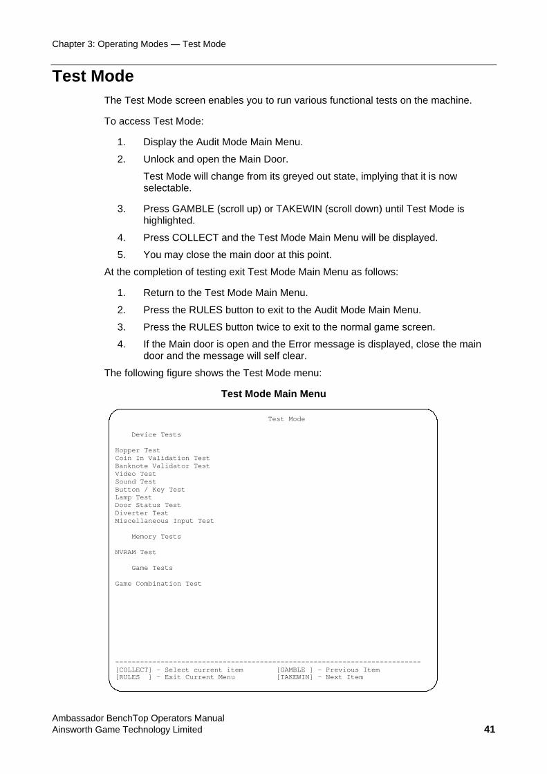
Test Mode The Test Mode screen enables you to run various functional tests on the machine.
To access Test Mode:
1. Display the Audit Mode Main Menu.
2. Unlock and open the Main Door.
Test Mode will change from its greyed out state, implying that it is now selectable.
3. Press GAMBLE (scroll up) or TAKEWIN (scroll down) until Test Mode is highlighted.
4. Press COLLECT and the Test Mode Main Menu will be displayed.
5. You may close the main door at this point.
At the completion of testing exit Test Mode Main Menu as follows:
1. Return to the Test Mode Main Menu.
2. Press the RULES button to exit to the Audit Mode Main Menu.
3. Press the RULES button twice to exit to the normal game screen.
4. If the Main door is open and the Error message is displayed, close the main door and the message will self clear.
The following figure shows the Test Mode menu:
Test Mode Main Menu
Test Mode Device Tests Hopper Test Coin In Validation Test Banknote Validator Test Video Test Sound Test Button / Key Test Lamp Test Door Status Test Diverter Test Miscellaneous Input Test Memory Tests NVRAM Test Game Tests Game Combination Test -------------------------------------------------------------------------- [COLLECT] – Select current item [GAMBLE ] – Previous Item [RULES ] - Exit Current Menu [TAKEWIN] – Next Item
Ambassador BenchTop Operators Manual Ainsworth Game Technology Limited 41
Chapter 3: Operating Modes — Test Mode
Device Tests The Device Tests menu enables testing of selected connected devices.
Access the Device Tests from the Test Mode menu. Select the required test and press COLLECT.
The tests are described in the following sections.
Hopper Test Use the Hopper Test to verify correct operation of the Hopper if fitted.
Notes:
• This only applies if a hopper is fitted.
• You must open the main door to initiate the Hopper Test, and then close it when prompted.
• Before you begin, ensure the hopper has an adequate supply of coins (minimum 10 coins). Once you have initiated the Hopper Test and dispensed some coins, there is no way to exit the test until you have reinserted the dispensed coins.
To start the Hopper Test:
1. Enter Test Mode, as described on page 41.
2. Make sure that there are at least ten coins in the hopper.
3. Select the Hopper Test from the Test Mode menu by using the GAMBLE and TAKEWIN buttons to scroll up and down.
4. Press the COLLECT button.
A red message will prompt you to close the Main Door. The coin-dispensing chute is attached to the Main Door, so the main door must be closed at this point to enable coins to be dispensed.
5. Close the Main Door.
6. Press COLLECT to initiate the hopper test. The EGM will dispense ten coins to the coin tray and confirm the count on the screen.
A red highlight message prompts you to re-insert the 10 coins. The Hopper Test screen shows the number of “Coins to Re-insert” and “Coins Re-inserted” progressively.
7. Re-insert the coins. When you have reinserted all ten coins an orange message appears noting ‘HOPPER TEST COMPLETE, PRESS RULES TO EXIT.’
8. Press the RULES button to exit the Hopper Test screen.
Ambassador BenchTop Operators Manual Ainsworth Game Technology Limited 42
Chapter 3: Operating Modes — Test Mode
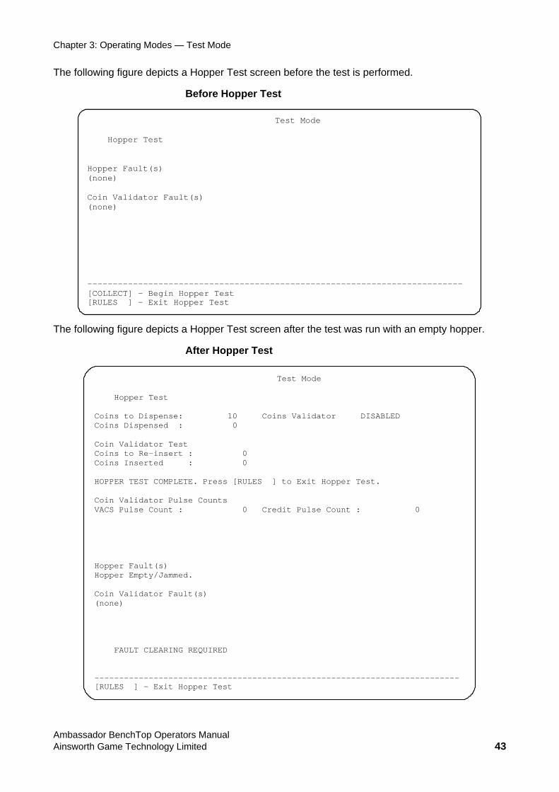
The following figure depicts a Hopper Test screen before the test is performed.
Before Hopper Test
Test Mode Hopper Test Hopper Fault(s) (none) Coin Validator Fault(s) (none) -------------------------------------------------------------------------- [COLLECT] – Begin Hopper Test [RULES ] - Exit Hopper Test
The following figure depicts a Hopper Test screen after the test was run with an empty hopper.
After Hopper Test
Test Mode Hopper Test Coins to Dispense: 10 Coins Validator DISABLED Coins Dispensed : 0 Coin Validator Test Coins to Re-insert : 0 Coins Inserted : 0 HOPPER TEST COMPLETE. Press [RULES ] to Exit Hopper Test. Coin Validator Pulse Counts VACS Pulse Count : 0 Credit Pulse Count : 0 Hopper Fault(s) Hopper Empty/Jammed. Coin Validator Fault(s) (none) FAULT CLEARING REQUIRED -------------------------------------------------------------------------- [RULES ] - Exit Hopper Test
Ambassador BenchTop Operators Manual Ainsworth Game Technology Limited 43
Chapter 3: Operating Modes — Test Mode
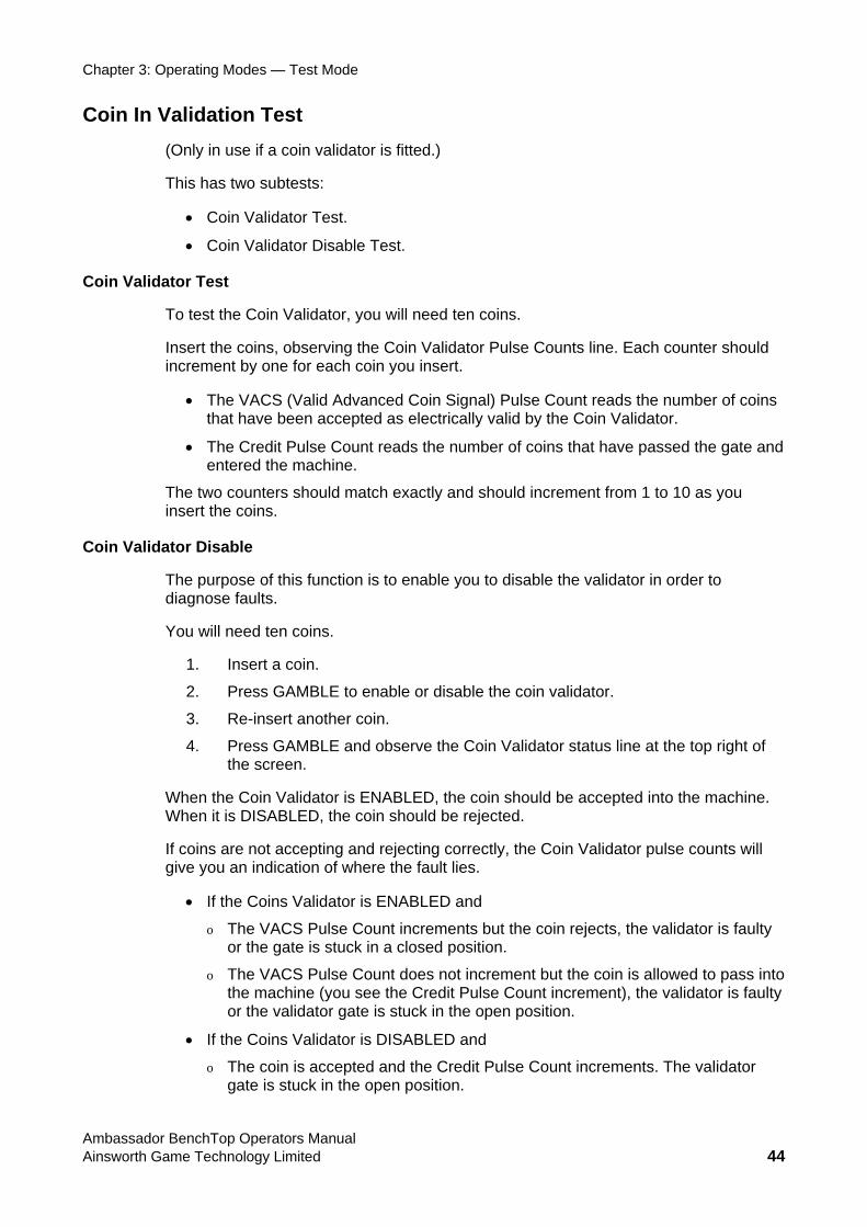
Coin In Validation Test (Only in use if a coin validator is fitted.)
This has two subtests:
• Coin Validator Test.
• Coin Validator Disable Test.
Coin Validator Test
To test the Coin Validator, you will need ten coins.
Insert the coins, observing the Coin Validator Pulse Counts line. Each counter should increment by one for each coin you insert.
• The VACS (Valid Advanced Coin Signal) Pulse Count reads the number of coins that have been accepted as electrically valid by the Coin Validator.
• The Credit Pulse Count reads the number of coins that have passed the gate and entered the machine.
The two counters should match exactly and should increment from 1 to 10 as you insert the coins.
Coin Validator Disable
The purpose of this function is to enable you to disable the validator in order to diagnose faults.
You will need ten coins.
1. Insert a coin.
2. Press GAMBLE to enable or disable the coin validator.
3. Re-insert another coin.
4. Press GAMBLE and observe the Coin Validator status line at the top right of the screen.
When the Coin Validator is ENABLED, the coin should be accepted into the machine. When it is DISABLED, the coin should be rejected.
If coins are not accepting and rejecting correctly, the Coin Validator pulse counts will give you an indication of where the fault lies.
• If the Coins Validator is ENABLED and
o The VACS Pulse Count increments but the coin rejects, the validator is faulty or the gate is stuck in a closed position.
o The VACS Pulse Count does not increment but the coin is allowed to pass into the machine (you see the Credit Pulse Count increment), the validator is faulty or the validator gate is stuck in the open position.
• If the Coins Validator is DISABLED and
o The coin is accepted and the Credit Pulse Count increments. The validator gate is stuck in the open position.
Ambassador BenchTop Operators Manual Ainsworth Game Technology Limited 44
Chapter 3: Operating Modes — Test Mode
Coin In Validator Test Screen
Ambassador BenchTop Operators Manual Ainsworth Game Technology Limited 45
Banknote Validator Test
Test Mode Coin In Validation Test
Coins Validator
: Disabled
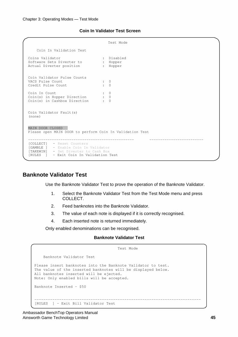
Banknote Validator Test Use the Banknote Validator Test to prove the operation of the Banknote Validator.
1. Select the Banknote Validator Test from the Test Mode menu and press COLLECT.
2. Feed banknotes into the Banknote Validator.
3. The value of each note is displayed if it is correctly recognised.
4. Each inserted note is returned immediately.
Only enabled denominations can be recognised.
Test Mode Banknote Validator Test Please insert banknotes into the Banknote Validator to test. The value of the inserted banknotes will be displayed below. All banknotes inserted will be ejected. Note: Only enabled bills will be accepted. Banknote Inserted - $50 -------------------------------------------------------------------------- [RULES ] - Exit Bill Validator Test
Software Sets Diverter to
: Hopper Actual Diverter position : Hopper Coin Validator Pulse Counts
VACS Pulse Count : 0 Credit Pulse Count : 0 Coin In Count
: 0 Coin(s) in Hopper Direction
: 0 Coin(s) in Cashbox Direction : 0 Coin Validator Fault(s)
(none) MAIN DOOR CLOSED Please open MAIN DOOR to perform Coin In Validation Test
-------------------------------------------------
-------------------------[COLLECT] –
– Reset Counters Enable Coin In Validator
[GAMBLE ]
– [TAKEWIN]
Exit Coin In Validation Test Set Diverter to Cash Box
- [RULES ]
Chapter 3: Operating Modes — Test Mode
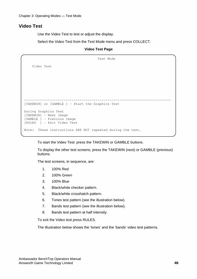
Video Test Use the Video Test to test or adjust the display.
Select the Video Test from the Test Mode menu and press COLLECT.
Video Test Page
Test Mode Video Test ------------ --------------------------- [TAKEWI t During [TAKEWIN] – Next Image [GAMBLE ] – Previous Image [RULES ] – Exit Video Test Note: These instructions ARE NOT repeated during the test.
To start the Video Test: press the TAKEWIN or GAMBLE buttons.
To display the other test screens, press the TAKEWIN (next) or GAMBLE (previous) buttons.
The test screens, in sequence, are:
1. 100% Red
2. 100% Green
3. 100% Blue
4. Black/white checker pattern.
5. Black/white crosshatch pattern.
6. Tones test pattern (see the illustration below).
7. Bands test pattern (see the illustration below).
es’ and the ‘bands’ video test patterns.
-----------------------------------N] or [GAMBLE ] – Start the Graphics Tes
Graphics Test
8. Bands test pattern at half intensity.
To exit the Video test press RULES.
The illustration below shows the ‘ton
Ambassador BenchTop Operators Manual Ainsworth Game Technology Limited 46
Chapter 3: Operating Modes — Test Mode
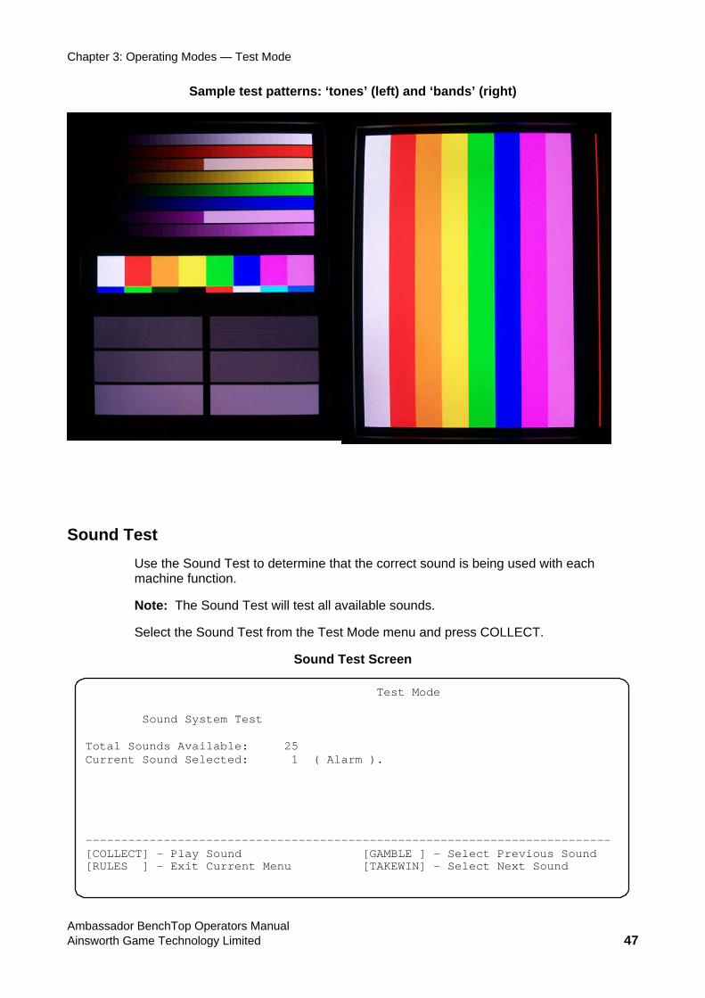
Sample test patterns: ‘tones’ (left) and ‘bands’ (right)
Sound Test Use the Sound Test to determine that the correct sound is being used with each machine function.
Note: The Sound Test will test all available sounds.
Select the Sound Test from the Test Mode menu and press COLLECT.
Sound Test Screen
Test Mode Sound System Test Total Sounds Available: 25 Current Sound Selected: 1 ( Alarm ). -------------------------------------------------------------------------- [COLLECT] – Play Sound [GAMBLE ] – Select Previous Sound [RULES ] - Exit Current Menu [TAKEWIN] – Select Next Sound
Ambassador BenchTop Operators Manual Ainsworth Game Technology Limited 47
Chapter 3: Operating Modes — Test Mode
• Pre d) buttons to select the number of the desired sound.
• Press COLLECT to play the sound.
• To exit the Sound Test press RULES button.
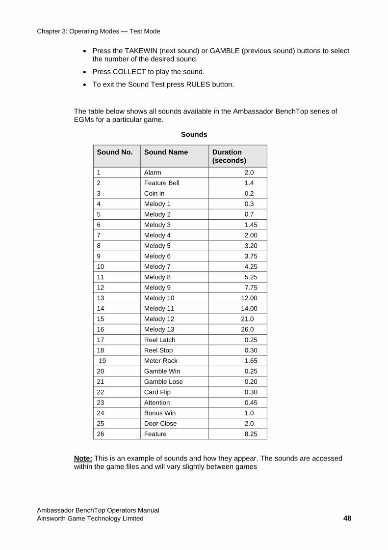
The table below shows all sounds available in the Ambassador BenchTop series of EGMs for a particular game.
Sounds
ss the TAKEWIN (next sound) or GAMBLE (previous soun
Sound No. Sound Name Duration (seconds)
1 Alarm 2.0 2 Feature Bell 1.4 3 Coin in 0.2 4 Melody 1 0.3 5 Melody 2 0.7 6 Melody 3 1.45 7 Melody 4 2.00 8 Melody 5 3.20 9 Melody 6 3.75 10 Melody 7 4.25 11 Melody 8 5.25 12 Melody 9 7.75 13 Melody 10 12.00 14 Melody 11 14.00 15 Melody 12 21.0 16 Melody 13 26.0 17 Reel Latch 0.25 18 Reel Stop 0.30 19 Meter 1.65 Rack 20 Gamble 0.25 Win 21 Gamble Lose 0.20 22 Card Flip 0.30 23 Attention 0.45 24 Bonus Win 1.0 25 Door Close 2.0 26 Feature 8.25
Note: This is an example of sounds and how they appear. The sounds are accessed within the game files and will vary slightly between games
Ambassador BenchTop Operators Manual Ainsworth Game Technology Limited 48
Chapter 3: Operating Modes — Test Mode
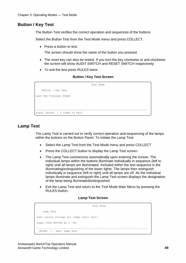
Button / KeyTh ion and sequences of the buttons.
Se d press COLLECT.
• Press a button to test.
e tested. If you turn the key clockwise or anti-clockwise the screen will show AUDIT and RESET SWITCH respectively.
• To exit the test press R
Button / Key Test
Test e Button Test verifies the correct operat
lect the Button Test from the Test Mode menu an
The screen should show the name of the button you pressed.
• The reset key can also b SWITCH
ULES twice.
Screen
Test Mode Button / Key Test Last Ke ressed: RULE ------- ------------ -------------------- -------------- Press [ ES ] 2 Time
Lamp Test The Lamp Test is carr verify correct operatio sequencing of the lamps within the buttons on Panel. To initiate the Lamp Test:
• Select the Lamp Test from the Test Mode menu OLLECT
• s the COL n to display the Lam st screen.
• Lamp Test s automatically upomps within the buttons illuminate individually in sequence (left to
right) until all lamps are illuminated. Included with sequence is the ext of the tower lights. Th ps then extinguish
idually in s ft to right) until all lamps are off. As the individual Lamp Test screen displays the designation
e lamp bei /extinguished.
• the Lamp T turn to the Test Mode Main Menu by pressing the on.
Test Screen
y P S
---RUL
------------s to EXIT
------
ied out to n andthe Button
and press C
Pres LECT butto p Te
The commence n entering the screen. The individual la
in the test e lamilluminating/ inguishing
indiv equence (lelamps illuminate and extinguish the of th ng illuminated
Exit est and reRULES butt
Lamp
Test Mode
p Test
-------------------------------------------------------------------------- [RULES ] - Exit Lamp Test
Lam
Test cycles through all lamps until exit. Lamp: PLAY BUTTON No 2 ON
Ambassador BenchTop Operators Manual Ainsworth Game Technology Limited 49
Chapter 3: Operating Modes — Test Mode
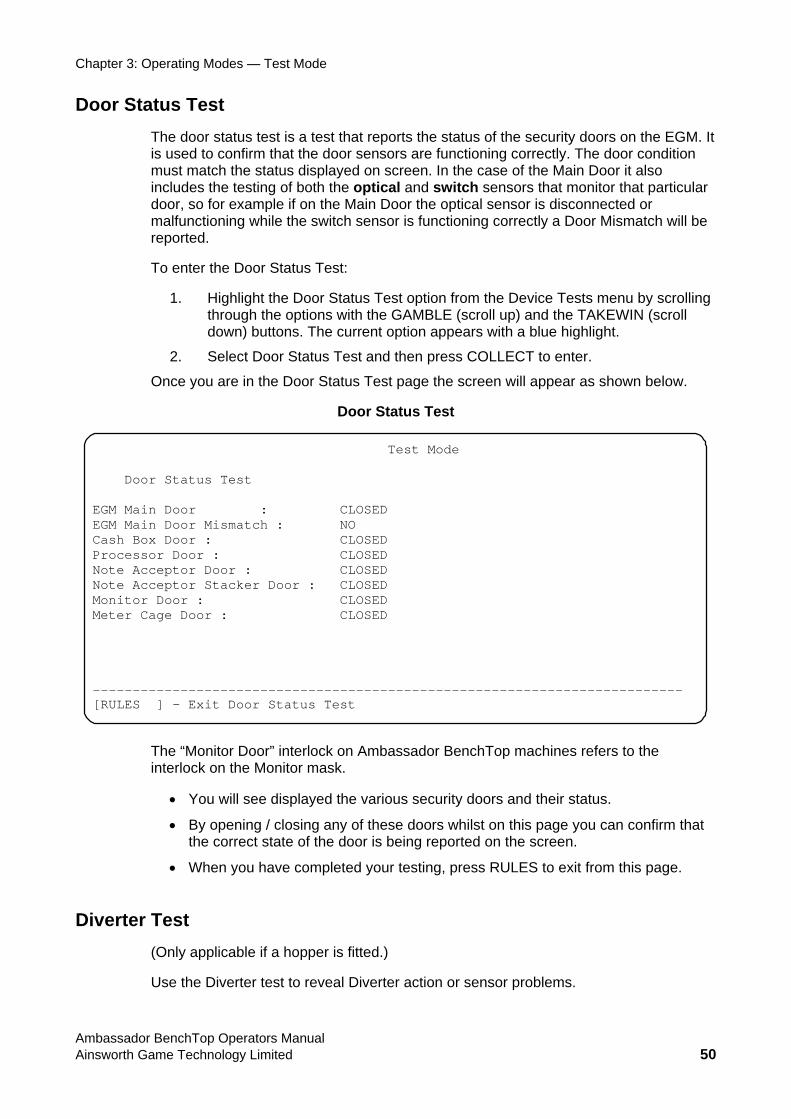
Door Status Test The door status test is a test that reports the status of the security doors on the EGM. It
n it also
includes optical and switch sensors that monitor that particular do Main Door the optical sensor is disconnected or malfu Mismatch will be reported.
To en
ion from the Device Tests menu by scrolling through the options with and the TAKEWIN (scroll down) buttons. ith a blue highlight.
2. Select Door Status Test and then press COLLECT to enter.
Once you are in the Door Status Test page the screen will appear as shown below.
Door Status Test
is used to confirm that the door sensors are functioning correctly. The door conditiomust match the status displayed on screen. In the case of the Main Door
the testing of both the or, so for example if on the
nctioning while the switch sensor is functioning correctly a Door
ter the Door Status Test:
1. Highlight the Door Status Test optthe GAMBLE (scroll up)
The current option appears w
Test Mode Door Status Test EGM Main Door : CLOSED EGM Main DoCash Box Do
or Mismatch : NO or : CLOSED
Processor Door : CLOSED Note AcNote AcMonitor Door : CLOSED Meter Cage o -------------[RULES ] - E
The “Minterlo
Y
• By opening / closing any of these doors whilst on this page you can confirm that the correct state of the d on the screen.
• When you have completed your testing, press RULES to exit from this page.
Diverter Test (Only applicable if a hopper is fitted.)
Use the Diverter test to reveal Diverter action or sensor problems.
ceptor Door : CLOSED ceptor Stacker Door : CLOSED
D or : CLOSED
------------------------------------------------------------- xit Door Status Test
onitor Door” interlock on Ambassador BenchTop machines refers to the ck on the Monitor mask.
• ou will see displayed the various security doors and their status.
door is being reporte
Ambassador BenchTop Operators Manual Ainsworth Game Technology Limited 50

Chapter 3: Operating Modes — Test Mode
The Diverter Hopper and C
test is used to confirm that the switching of the diverter between the ashbox is functioning correctly.
ress COLLECT to enter.
re the Software is setting the diverter to (i.e. Cashbox diverter is Physically being set. Both must be the
sa
If the div then the diverter should in the unit.
• Press GAMBLE to switch the diverter to the Hopper.
• Press TAKEWIN to switch the diverter to the Cashbox.
To Exit the test press the Rules button.
Diverter Test
To enter the Diverter Test,
1. Highlight the Diverter Test option from the Device Tests menu. This is done by scrolling through the options with the GAMBLE (scroll up) and the TAKEWIN (scroll down) buttons. The current option appears with a blue highlight.
2. P
On screen will be displayed wheor Hopper) and secondly, where the
me.
erter is set by the software to be positioned to dispense coins to the hopperphysically be set to hopper, if not then there is a malfunction
The test allows you to switch the diverter between Hopper and Cashbox.
Test Mode Diverter Test Software Sets Diverter to : Cash Box Actual Diverter position points to : Cash Box -------------------------------------------------------------------------- [GAMBLE ] – Set Diverter to Hopper [TAKEWIN] – Set Diverter to Cash Box [RULES ] – Exit Diverter Test
MiscellaneThthe H
d.
• Hopper Connection status. It tests to determine whether the hopper connect / sconnect is acknowledged correctly by the EGM.
hether the Coin Out sensor is functioning and ctly.
ous Input Test e Miscellaneous Input test can be used to determine the operational functionality of
opper (only applies if a hopper is fitted), and the hard meters.
• Hopper Level. It tests to determine whether a hopper full level is acknowledge
di
• Coin Out Sensor. It determines wcoins are being registered corre
Ambassador BenchTop Operators Manual Ainsworth Game Technology Limited 51
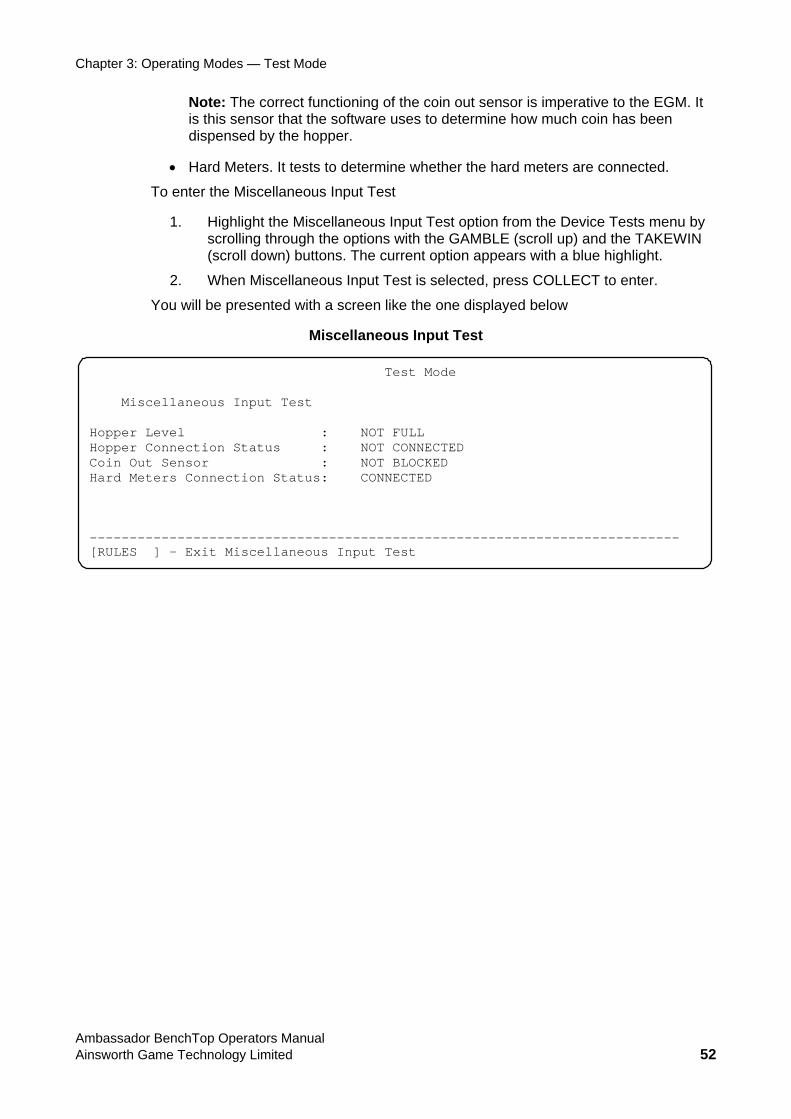
Chapter 3: Operating Modes — Test Mode
Note: The correct functioning of the coin out sensor is imperative to the EGMis this sensor that the software uses to d
. It etermine how much coin has been
dispensed by the hopper.
Hard Meters
To ter
1. nu by s with the GAMBLE (scroll up) and the TAKEWIN
l be presented with a screen like the one displayed below
• . It tests to determine whether the hard meters are connected.
en the Miscellaneous Input Test
Highlight the Miscellaneous Input Test option from the Device Tests mescrolling through the option(scroll down) buttons. The current option appears with a blue highlight.
2. When Miscellaneous Input Test is selected, press COLLECT to enter.
You wil
Miscellaneous Input Test
Test Mode Miscellaneous Input Test Hopper Level : NOT FULL Hopper Connection Status : NOT CONNECTED Coin Out OCKED Hard Met TED -------------------------------------------------------------------------- [RULES ] - Exit Miscellaneous Input Test
Sensor : NOT BLers Connection Status: CONNEC
Ambassador BenchTop Operators Manual Ainsworth Game Technology Limited 52
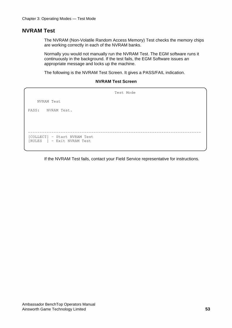
Chapter 3: Operating Modes — Test Mode
NVRAM TestThe N om Access Memory) Test checks the memory chips are working correctly in
e NVRAM Test. The EGM software runs it st fails, the EGM Software issues an
ap pri
The follo
VRAM (Non-Volatile Rand
each of the NVRAM banks.
Normally you would not manually run thcontinuously in the background. If the te
pro ate message and locks up the machine.
wing is the NVRAM Test Screen. It gives a PASS/FAIL indication.
NVRAM Test Screen
Test Mode NVRAM Test PASS: NVRAM Test. --------------------------------------------------------------------------[COLLECT] – Start NVRAM Test [RULES ] - Exit NVRAM Test
If the NVRAM Test fails, contact your Field Service representative for instructions.
Ambassador BenchTop Operators Manual Ainsworth Game Technology Limited 53
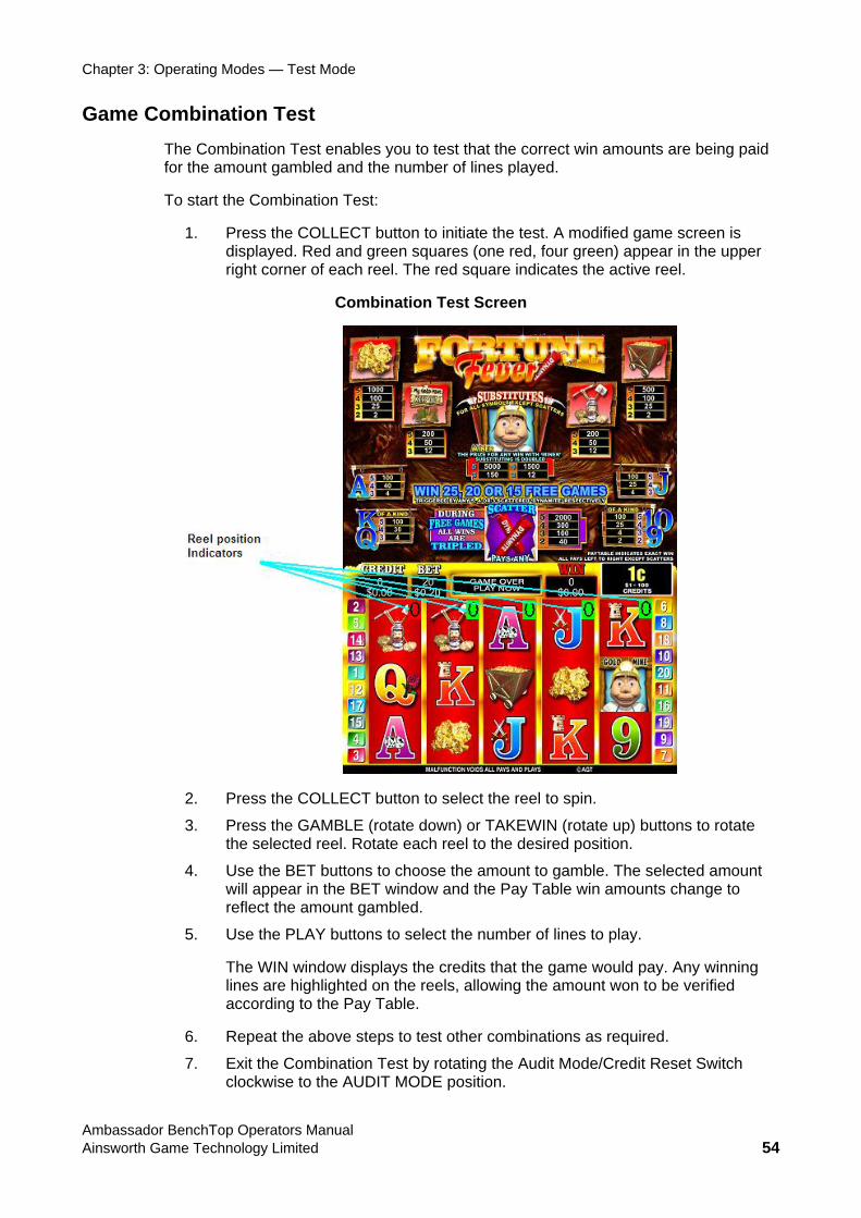
Chapter 3: Operating Modes — Test Mode
Game Combination Test
ed.
test. A modified game screen is displayed. Red and green squares (one red, four green) appear in the upper
Combination Test Screen
The Combination Test enables you to test that the correct win amounts are being paidfor the amount gambled and the number of lines play
To start the Combination Test:
1. Press the COLLECT button to initiate the
right corner of each reel. The red square indicates the active reel.
2. Press the COLLECT button to select the reel to spin.
3. Press the GAMBLE (rotate down) or TAKEWIN (rotate up) buttons to rotate the selected reel. Rotate each reel to the desired position.
4. Use the BET buttons to choose the amount to gamble. The selected amount will appear in the BET window and the Pay Table win amounts change to reflect the amount gambled.
5. Use the PLAY buttons to select the number of lines to play.
The WIN window displays the credits that the game would pay. Any winning lines are highlighted on the reels, allowing the amount won to be verified according to the Pay Table.
6. Repeat the above steps to test other combinations as required.
7. Exit the Combination Test by rotating the Audit Mode/Credit Reset Switch clockwise to the AUDIT MODE position.
Ambassador BenchTop Operators Manual Ainsworth Game Technology Limited 54
Chapter
OPERATOR ROUTINE SERVICING
General Maintenance This chapter provides information for routine servicing of the Ambassador BenchTop series EGM. The instructions are limited to those that are deemed appropriate to be carried out on-site with minimum disruption to the machine operation. More advanced information, and a listing of failure and status messages can be found at the end of this chapter.
Caution: when cleaning the machine do not use any abrasive or solvent. Do not use any bleaching or chlorine agents. Take care that no cleaning solution enters the machine.
Cabinet Body Cleaning There are no specific maintenance requirements for the Cabinet Body other than cleaning.
Clean the exterior of the Cabinet Body using a mild detergent solution and a damp cloth.
Main Door Cleaning Cle th .
Cautioncleaning
an e Main Door using a mild detergent solution and a damp cloth
: Ensure that no solution enters the control panel buttons while .
Ambassador BenchTop Operators Manual Ainsworth Game Technology Limited 55
Chapter 4: Operator Routine Servicing — Monitor Cleaning
perators Manual Ainsworth Game Technology Limited 56
Monitor Cleaning Warning: Do not open the Monitor. Very high voltages are present inside; there is risk of electric shock. Ensure no cleaning solution enters. Only qualified Service Personnel should open the monitor.
Clean the monitor screen with a mild detergent solution and a damp cloth.
Banknote Stacker Assembly
Removing and Replacing the Banknote Stacker The followingBanknote Stacker is from one specific manufacturer and hence depending on Banknote Stacker manufacturer, the method of removing and replacing Banknote
ker Door is unlocked and opened while the machine is on,
e the locking lever and slide the Banknote Stacker all the way out.
The following procedure details how to install the Banknote Stacker.
Stacker Door with the appropriate key. Open the door
nto lace.
Close the Main Door.
When you have finished, you must reset the machine by rotating the Credit Reset/Audit Mode switch momentarily to the Credit Reset position.
Removing, Dismantling and Replacing the Banknote Validator oving
te Validator are to clear minor jams and to clean it. (Note: The Banknote Validator shown is from one specific manufacturer and hence depending on Banknote Validator manufacturer, the method of removing, dismantling and replacing Banknote Validator may differ).
procedure details how to remove the Banknote Stacker. (Note: The
Stacker may differ).
Note: If the Banknote Stacalarms will sound and messages will be generated.
1. Open the Main Door.
2. Unlock the Banknote Stacker Door with the appropriate key. Open the door forward.
3. You will see a locking lever on the right. Depress it.
4. Grasp the Banknote Stacker handle and slide the stacker out part-way. Then releas
1. Unlock the Banknote forward.
2. Position the Banknote Stacker in the opening and slide it in until it clicks ip
3. Close and lock the Banknote Stacker Door.
4.
Use this procedure to remove the Banknote Validator. The only reasons for remthe Bankno
Ambassador BenchTop O
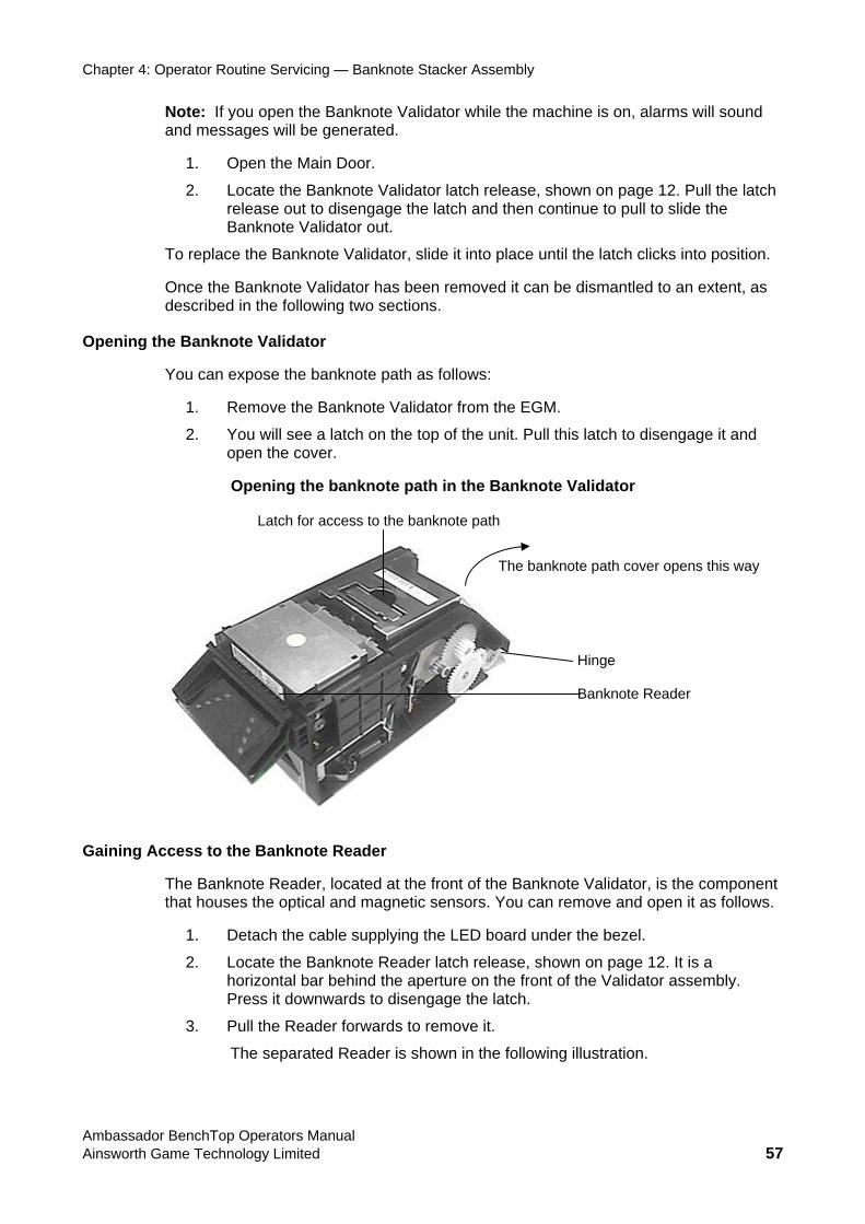
Chapter 4: Operator Routine Servicing — Banknote Stacker Assembly
y Limited 57
e Banknote Validator while the machine is on, alarms will sound e generated.
d then continue to pull to slide the
To replace the Banknote Validator, slide it into place until the latch clicks into position.
removed it can be dismantled to an extent, as
Opening the Banknote Validator
d ver.
Note: If you open thand messages will b
1. Open the Main Door.
2. Locate the Banknote Validator latch release, shown on page 12. Pull the latch release out to disengage the latch anBanknote Validator out.
Once the Banknote Validator has been described in the following two sections.
You can expose the banknote path as follows:
1. Remove the Banknote Validator from the EGM.
2. You will see a latch on the top of the unit. Pull this latch to disengage it anopen the co
Opening the banknote path in the Banknote Validator
Latch for access to the banknote path
eader
Gaining Ac
ote Validator, is the component that houses the optical and magnetic sensors. You can remove and open it as follows.
he following illustration.
Hinge Banknote R
The banknote path cover opens this way
cess to the Banknote Reader
The Banknote Reader, located at the front of the Bankn
1. Detach the cable supplying the LED board under the bezel.
2. Locate the Banknote Reader latch release, shown on page 12. It is a horizontal bar behind the aperture on the front of the Validator assembly. Press it downwards to disengage the latch.
3. Pull the Reader forwards to remove it.
The separated Reader is shown in t
Ambassador BenchTop Operators Manual Ainsworth Game Technolog
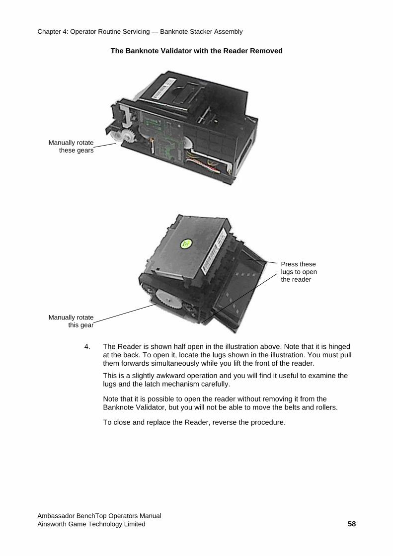
Chapter 4: Operator Routine Servicing — Banknote Stacker Assembly
The Banknote Validator with the Reader Removed
Manually
Manually rotate this gea
rotate these gears
r
Press these lugs to open the reader
4. The Reader is shown half open in the illustration above. Note that it is hinged at the back. To open it, locate the lugs shown in the illustration. You must pull them forwards simultaneously while you lift the front of the reader.
This is a slightly awkward operation and you will find it useful to examine the anism carefully.
lugs and the latch mech
Note that it is possible to open the reader without removing it from the Banknote Validator, but you will not be able to move the belts and rollers.
To close and replace the Reader, reverse the procedure.
Ambassador BenchTop Operators Manual Ainsworth Game Technology Limited 58
Chapter 4: Operator Routine Servicing — Banknote Stacker Assembly
Banknote ValidaTo clear jams in the Banknote Validator you may try this procedure. Do not attempt any other maintenance of the Banknote Validator; call Service if this procedure does not solve the problem.
The procedure is to open the banknote path and the banknote reader and try carefully to clear the jam if possible.
You can move the belts in the banknote path by manually rotating the gears on the left hand sides of the validator and reader. The gears are noted in the illustration on page
e Banknote Validator as described on the next page.
When you have finished, you must reset the machine by rotating the Credit Reset/Audit Mode switch momentarily to the Credit Reset position.
If this procedure does not solve the problem, call a Service Technician.
Banknote Validator Cleaning The Banknote Validator may reject notes with increased frequency as deposits on the validator sensors accumulate. If the Banknote Validator requires cleaning the following procedure is to be used:
Caution: Use a 90% solution of isopropyl alcohol to clean the Banknote Validator. The use of other solvents may damage the optical sensors. Ensure that excess cleaning solution does not enter the Banknote V
1. As with the jam clearing procedure, open the banknote path and the banknote
Using a soft lint-free cloth dampened with isopropyl alcohol, wipe the note channel surfaces in the banknote path to remove any accumulated residue. You can move the belts in the banknote path by manually rotating the gears
3. lcohol
4. rface
This gear is noted
5. Power up the EGM and conduct a Banknote Validator test (see Banknote Validator Test, next).
tor Jam Clearing
58.
Test th
2.
alidator.
reader.
on the left hand side of the unit. The gears are noted in the illustration on page58.
Using a soft lint-free cloth or cotton bud dampened with isopropyl aremove any residue accumulated on the optical sensors and magnetic heads in the banknote reader. Remove any excess cleaning solution.
Using a soft lint-free cloth dampened with isopropyl alcohol clean the suof the pressure rollers and belts in the banknote reader. You can move therollers and belts in the reader (while holding the cloth against them) by manually rotating the gear on the left hand side of the unit.in the illustration on page 58.
Ambassador BenchTop Operators Manual Ainsworth Game Technology Limited 59
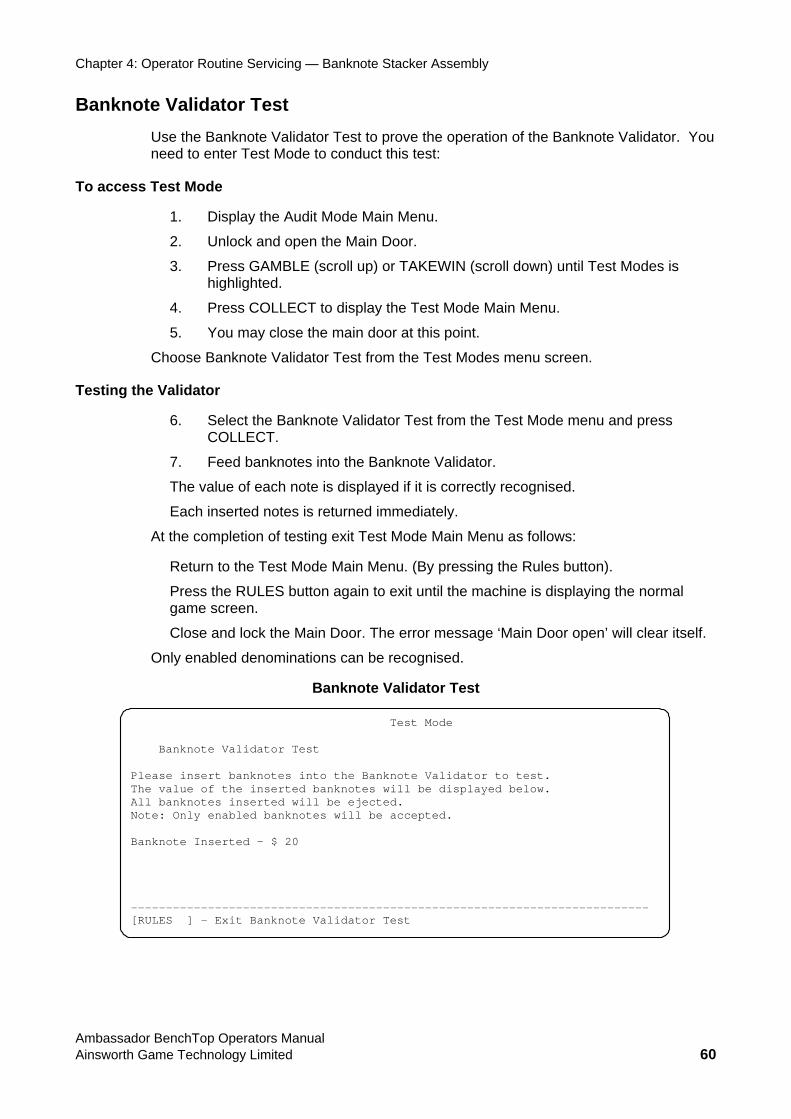
Chapter 4: Operator Routine Servicing — Banknote Stacker Assembly
Banknote Validator Test Use the Banknote Validator Test to prove the operation of the Banknote Validator. You need to enter Test Mode to conduct this test:
To access Test Mode
ode Main Menu.
highlighted.
u.
enu screen.
Testing the
6. Select the Banknote Validator Test from the Test Mode menu and press
returned immediately.
lf.
Only ena
1. Display the Audit M
2. Unlock and open the Main Door.
3. Press GAMBLE (scroll up) or TAKEWIN (scroll down) until Test Modes is
4. Press COLLECT to display the Test Mode Main Men
5. You may close the main door at this point.
Choose Banknote Validator Test from the Test Modes m
Validator
COLLECT.
7. Feed banknotes into the Banknote Validator.
The value of each note is displayed if it is correctly recognised.
Each inserted notes is
At the completion of testing exit Test Mode Main Menu as follows:
Return to the Test Mode Main Menu. (By pressing the Rules button).
Press the RULES button again to exit until the machine is displaying the normal game screen.
Close and lock the Main Door. The error message ‘Main Door open’ will clear itse
bled denominations can be recognised.
Banknote Validator Test
Test Mode Banknote Validator Test
rt banknotes into the Banknote Validator to test. Please inseThe value oAll banknotNote: Only Banknote In ----------- ------------------------------------------ [RULES ] - Exit Banknote Validator Test
f the inserted banknotes will be displayed below. es inserted will be ejected. enabled banknotes will be accepted.
serted - $ 20
---------------------
Ambassador BenchTop Operators Manual Ainsworth Game Technology Limited 60
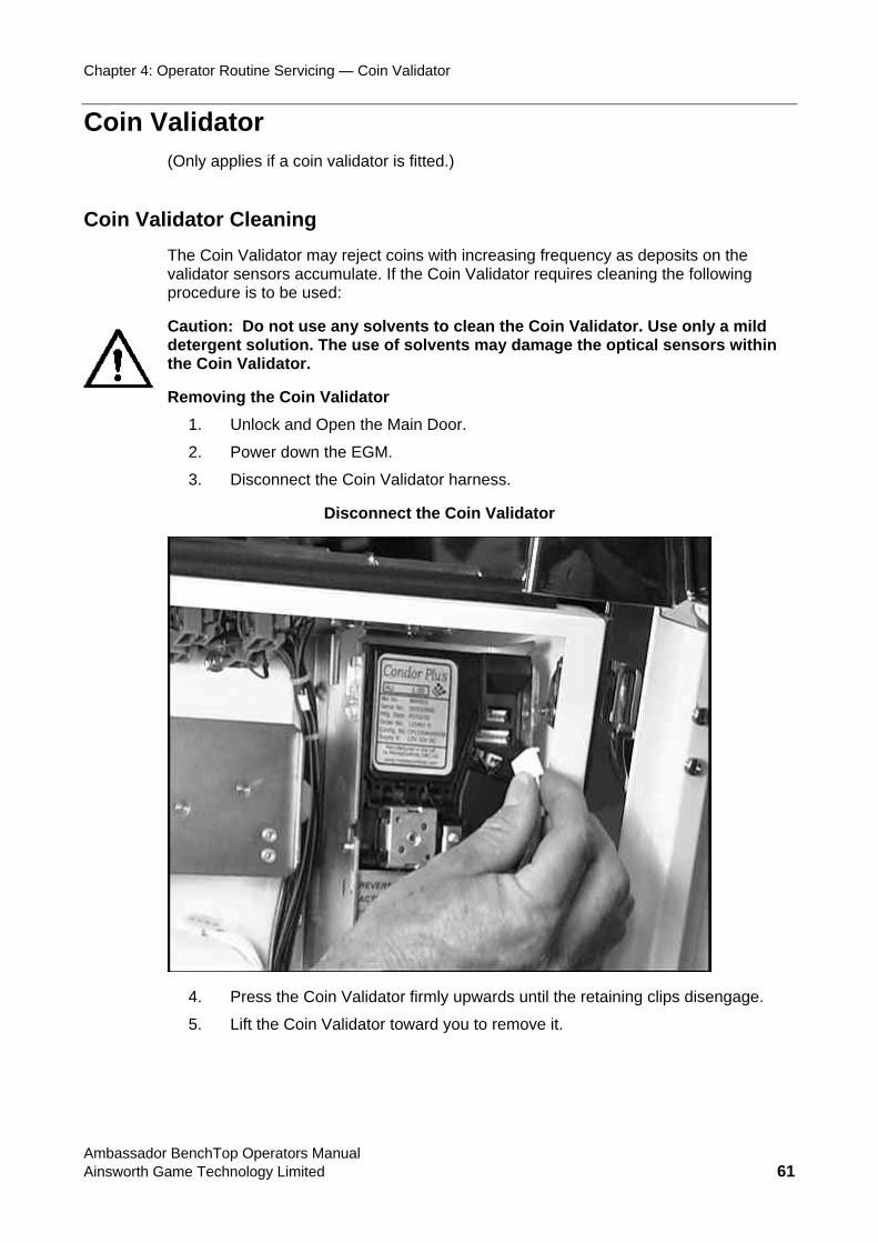
Chapter 4: Operator Routine Servicing — Coin Validator
Coin Validator (Only applies if a coin validator is fitted.)
Coin Validator Cleaning The Coin Validator may reject coins s on the va tor alidator requires cleaning the following pro u
Caution: Do not use any solvents to clean the Coin Validator. Use only a mild de e ical sensors within the in
ock and Open the Main Door.
2. Power down the EGM.
with increasing frequency as depositlida sensors accumulate. If the Coin Vced re is to be used:
terg nt solution. The use of solvents may damage the opt Co Validator.
Removing the Coin Validator 1. Unl
3. Disconnect the Coin Validator harness.
Disconnect the Coin Validator
4. Press the Coin Validator firmly upwards until the retaining clips disengage.
5. Lift the Coin Validator toward you to remove it.
Ambassador BenchTop Operators Manual Ainsworth Game Technology Limited 61
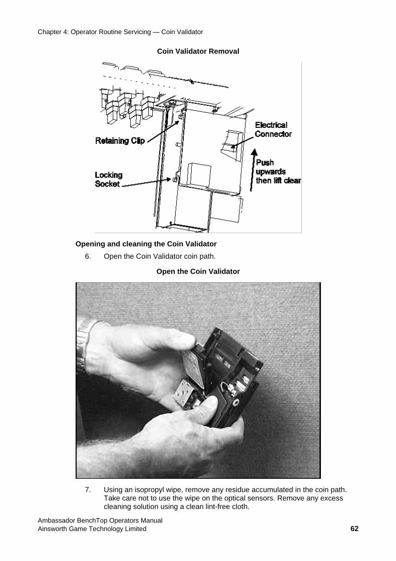
Chapter 4: Operator Routine Servicing — Coin Validator
Coin Validator Removal
Opening and cleaning the Coin Validator 6. Open the Coin Validator coin path.
Open the Coin Validator
7. Using an isopropyl wipe, remove any residue accumulated in the coin path. Take care not to use the wipe on the optical sensors. Remove any excess cleaning solution using a clean lint-free cloth.
Ambassador BenchTop Operators Manual Ainsworth Game Technology Limited 62
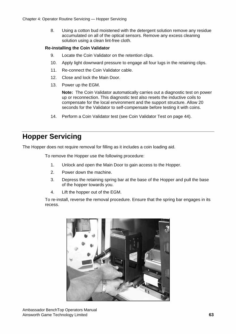
Chapter 4: Operator Routine Servicing — Hopper Servicing
8. Using a cotton bud moistened with the detergent solution remove any residue accumulated on all of the optical sensors. Remove any excess cleaning solution using a clean lint-free cloth.
Re-installing the Coin Validator 9. Locate the Coin Validator on the retention clips.
10. Apply light downward pressure to engage all four lugs in the retaining clips.
11. Re-connect the Coin Validator cable.
12. Close and lock the Main Door.
13. Power up the EGM.
Note: The Coin Validator automatically carries out a diagnostic test on power up or reconnection. This diagnostic test also resets the inductive coils to compensate for the local environment and the support structure. Allow 20 seconds for the Validator to self-compensate before testing it with coins.
14. Perform a Coin Validator test (see Coin Validator Test on page 44).
Hopper Servicing The Hoppe des a coin loading aid.
To remove t e:
1. Unlock and open the Main Door to gain access to the Hopper.
2. Power down the machine.
3. Depress the retaining spring bar at the base of the Hopper and pull the base of the hopper towards you.
4. Lift the hopper out of the EGM.
To re-install, reverse the removal procedure. Ensure that the spring bar engages in its recess.
r does not require removal for filling as it inclu
he Hopper use the following procedur
Ambassador BenchTop Operators Manual Ainsworth Game Technology Limited 63
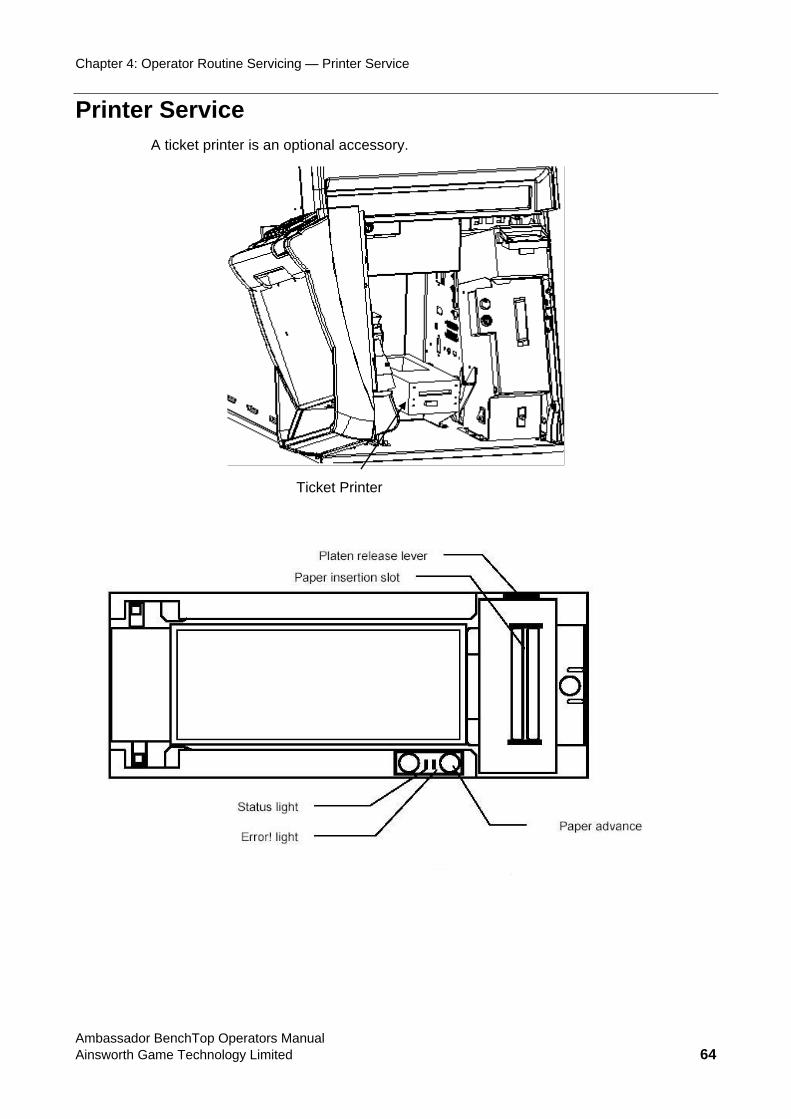
Chapter 4: Operator Routine Servicing — Printer Service
Printer S rve ice A ticket printer is an optional accessory.
Ticket Printer
Ambassador BenchTop Operators Manual Ainsworth Game Technology Limited 64

Chapter 4: Operator Routine Servicing — Printer Service
Paper Loading 1. Place the paper stack in the printer as indicated by the band around the stack and the label
in the bottom of the paper tray.
2. Insert paper into the paper loading slot; the printer will automatically pull through a form or two, leaving it registered at the top of a form. Remove the excess tickets from the printer.
Ambassador BenchTop Operators Manual Ainsworth Game Technology Limited 65
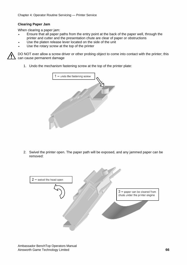
Chapter 4: Operator Routine Servicing — Printer Service
Clearing Paper Jam Wh c• E he entry point at the back of the paper well, through the
printer and cutter and the presentation chute are clear of paper or obstructions • Use the platen release lever located on the side of the unit • Use the rotary screw at the top of the printer DO NOT ever allow a screw driver or other probing object to come into contact with the printer; this can cause permanent damage
1. Undo the mechanism fastening screw at the top of the printer plate:
en learing a paper jam: nsure that all paper paths from t
2. Swivel the printer open. The paper path will be exposed, and any jammed paper can be removed:
Ambassador BenchTop Operators Manual Ainsworth Game Technology Limited 66
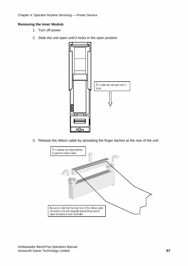
Chapter 4: Operator Routine Servicing — Printer Service
Removing the Inner Module 1. Turn off power
2. Slide the unit open until it locks in the open position
3. Release the ribbon cable by spreading the finger latches at the rear of the unit:
Ambassador BenchTop Operators Manual Ainsworth Game Technology Limited 67
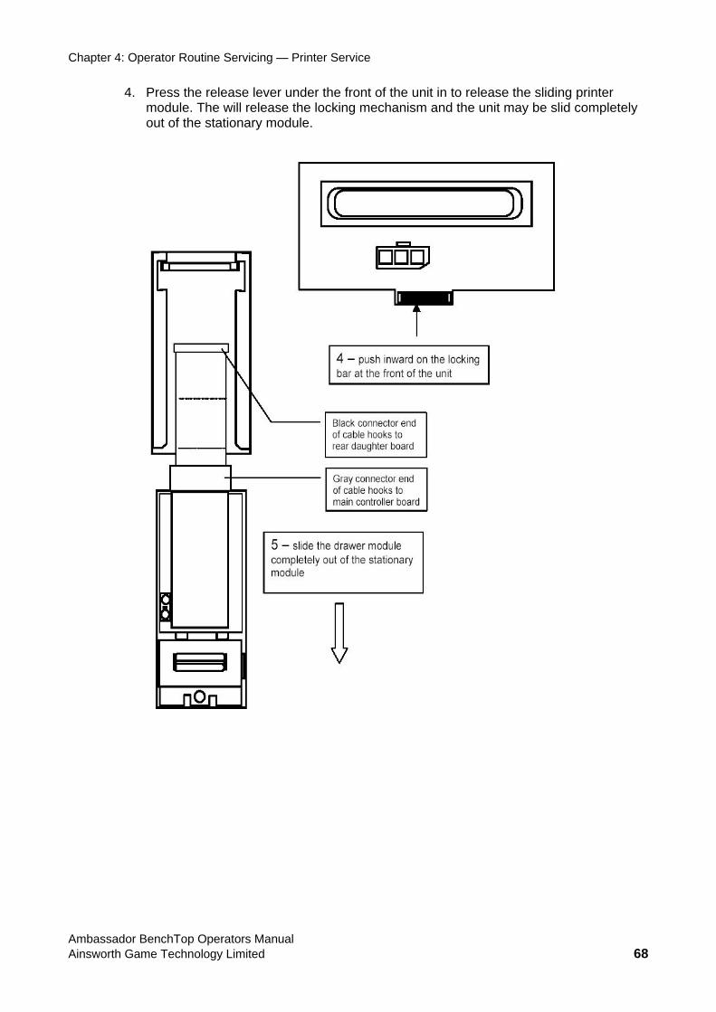
Chapter 4: Operator Routine Servicing — Printer Service
4. Press the release lever under the front of the unit in to release the sliding printer l release the locking mechanism and the unit may be slid completely ary module.
module. The wilout of the station
Ambassador BenchTop Operators Manual Ainsworth Game Technology Limited 68

Chapter 4: Operator Routine Servicing — Fuse Replacement
Fuse Replacement WARNING:
Disconnect the machine from the electrical supply prior to carrying out any maintenance on the fuse or power supply, and ensure no other person can re-
connect the supply while you are working. You risk electric shock by attempting any maintenance with electrical power applied.
1. Disconnect the EGM from the electrical supply.
2. Unlock and open the Main Door.
3. Check that the EGM Power Switch is OFF (light is OFF within the switch).
4. (Only if a hopper is fitted.) Remove the Hopper.
The fuse holder is a bayonet cartridge type mounted on the lower left of the front panel of the power supply just above the supply input lead.
5. Remove the fuse by turning the carrier counter clockwise. Remove the carrier.
6. Replace the fuse in the carrier with a metric M205T 4 Amp Slow-blow fuse.
7. Insert the carrier into the fuse holder and turn clockwise to lock.
8. Connect electrical power to the machine and then switch on the EGM Power Switch.
9. Verify that the power switch internal light (red) illuminates (confirms power to the power supply).
10. Verify that the Power Supply “Power Good” light (yellow) comes on and remains steady (confirms the Power Supply successfully started).
Button LED Replacement The player push-buttons are fitted with LEDs which usually last longer than the life of the machine. If one fails to illuminate, the fault is not usually the LED.
To replace a Button LED:
Warning: Power down the EGM prior to replacing LEDs.
1. Unlock and open the Main Door and gain access to the underside of the Button Panel. Power down the EGM.
2. Grasp the base of the button and rotate counter clockwise (approx. 45ºC) to disengage from the body. The LED base can now be removed from the body.
3. Remove the faulty LED and insert a serviceable LED.
4. Re-seat the base in the body and rotate the base clockwise (approx. 45ºC).
5. Close and lock the Main Door.
6. Power up the EGM.
7. Verify that the Button Lamps operate by carrying out a Lamp Test (see = on page 49).
Ambassador BenchTop Operators Manual Ainsworth Game Technology Limited 69
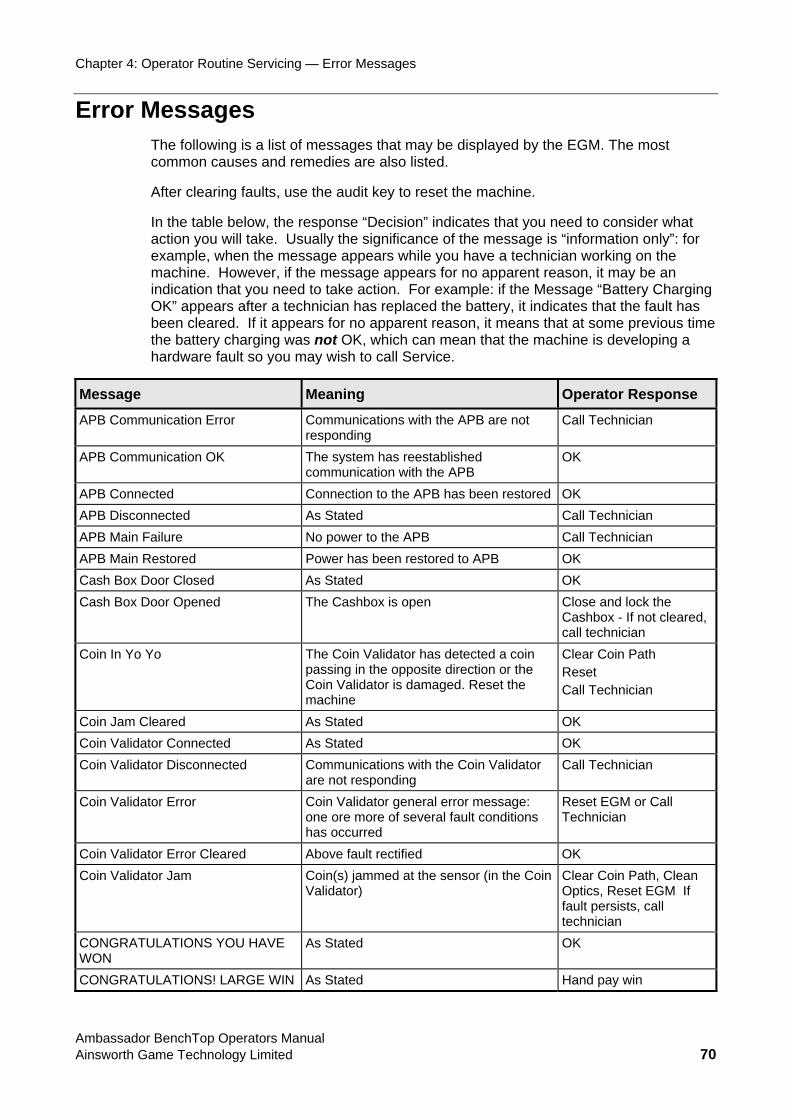
Chapter 4: Operator Routine Servicing — Error Messages
Error Messages The following is a list of messages tha layed by the EGM. The most common causes and remedies are also listed.
A
action you will take ation only”: for example, when the message appearma ne ent reason, it may be an ind tio r example: if the Message “Battery Charging OK pp s be le ime the tte e machine is developing a hardwar
t may be disp
fter clearing faults, use the audit key to reset the machine.
In the table below, the response “Decision” indicates that you need to consider what . Usually the significance of the message is “inform
s while you have a technician working on the chi . However, if the message appears for no apparica n that you need to take action. Fo” a ears after a technician has replaced the battery, it indicates that the fault ha
en c ared. If it appears for no apparent reason, it means that at some previous t ba ry charging was not OK, which can mean that th
e fault so you may wish to call Service.
Message Meaning Operator Response
APB Communication Error Communications with the APB are not Call Technician responding
APB Communication OK The system has reestablished communication with the APB
OK
APB Connected Connection to the APB has been restored OK APB Disconnected As Stated Call Technician APB Main Failure No power to the APB Call Technician APB Main Restored Power has been restored to APB OK Cash Box Doo er Clos d As Stated OK Cash Box Door Opened The Cashbox is open Close and lock the
Cashbox - If not cleared, call technician
Coin In Yo Yo The Coin Vpassing in t
alidator has detected a coin he opposite direction or the
Clear Coin Path Reset
Coin Validator is damaged. Reset the machine
Call Technician
Coin Jam Cleared As Stated OK Coin Valida Stated OK tor Connected AsCoin Valida
are not responding Call Technician tor Disconnected Communications with the Coin Validator
Coin Validator Error ault conditions Technician
Coin Validator general error message: one ore more of several f
Reset EGM or Call
has occurred Coin Validator Error Cleared Above fault rectified OK Coin Validator Jam Clear Coin Path, Clean
Optics, Reset EGM If
technician
Coin(s) jammed at the sensor (in the Coin Validator)
fault persists, call
CONGRATULATIONS YOU HAVE WON
OK As Stated
CONGRATULA NTIO S! LARGE WIN As Stated Hand pay win
Ambassador BenchTop Operators Manual Ainsworth Game Technology Limited 70
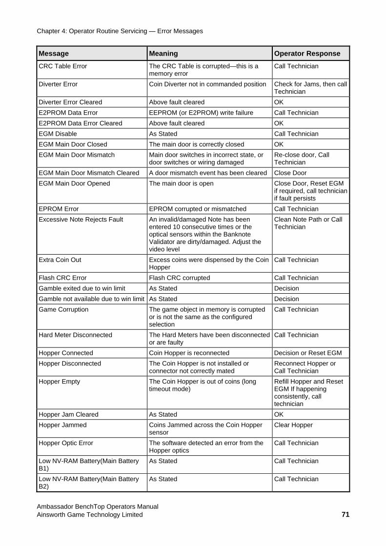
Chapter 4: Operator Routine Servicing — Error Messages
Message Meaning Operator Response
CRC Table Error The CRC Table is corrupted—this is a memory error
Call Technician
Diverter Erro anded position Check for Jams, then call Technician
r Coin Diverter not in comm
Diverter Error Cleared Above fault cleared OK E2PROM Data Error EEPROM (or E2PROM) write failure Call Technician E2PROM Data Error Cleared Above fault cleared OK EGM Disable As Stated Call Technician EGM Main Door Closed The main door is correctly closed OK EGM Main Door Mismatch Main door switches in incorrect state, or
door switches or wiring damaged Re-close door, Call Technician
EGM Main D been cleared Close Door oor Mismatch Cleared A door mismatch event hasEGM Main Door Opened The main door is open Close Door, Reset EGM
n if required, call techniciaif fault persists
EPROM Error EPROM corrupted or mismatched Call Technician Excessive Note Rejects Fault een
r the knote
n Note Path or Call nician
An invalid/damaged Note has bentered 10 consecutive times ooptical sensors within the BanValidator are dirty/damaged. Adjust the video level
CleaTech
Extra Coin Out Excess coins were dispensed by the Coin Hopper
Call Technician
Flash CRC Error Flash CRC corrupted Call Technician Gamble exited due to win limit As Stated Decision Gamble not available due to win limit As Stated Decision Game Corruption The game object in memory is corrupted
or is not the same as the configured selection
Call Technician
Hard Meter Disconnected lty
The Hard Meters have been disconnected or are fau
Call Technician
Hopper Connected Coin Hopper is reconnected sion or Reset EGM DeciHopper Disconnected The Coin Hopper is not installed or nnect Hopper or
connector not correctly mated RecoCall Technician
Hopper Empty s (long Refill Hopper and Reset The Coin Hopper is out of cointimeout mode) EGM If happening
consistently, call technician
Hopper Jam Cleared As Stated OK Hopper Jammed Coins Jammed across the Coin Hopper
sensor Clear Hopper
Hopper Optic Error The software detected an error from the Hopper optics
Call Technician
Low NV-RAM Battery(Main Battery B1)
As Stated Call Technician
Low NV-RAM Battery(Main Battery B2)
As Stated Call Technician
Ambassador BenchTop Operators Manual Ainsworth Game Technology Limited 71
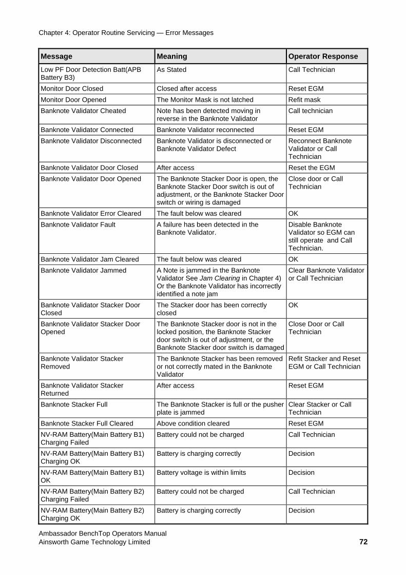
Chapter 4: Operator Routine Servicing — Error Messages
Message Meaning Operator Response
Low PF Door Detection Batt(APB Battery B3)
As Stated Call Technician
Monitor Door Closed Closed after access Reset EGM Monitor Door Opened The Monitor Mask is not latched Refit mask Banknote Validator Cheated ted moving in technician Note has been detec
reverse in the Banknote Validator Call
Banknote Validator Connected econnected t EGM Banknote Validator r ReseBanknote Validator Disconnected alidator is disconnected or note
ator or Call nician
Banknote VBanknote Validator Defect
Reconnect BankValidTech
Banknote Validator Door Closed After access Reset the EGM Banknote Validator Door Opened The Banknote Stacker Door is open, the
Banknote Stacker Door switch is out of adjustment, or the Banknote Stacker Door switch or wiring is damaged
r Call Close door oTechnician
Banknote Validator Error Cleared The fault below was cleared OK Banknote Validator Fault
and Call Technician.
A failure has been detected in the Banknote Validator.
Disable Banknote Validator so EGM can still operate
Banknote Validator Jam Cleared OK The fault below was cleared Banknote Validator Jammed
has incorrectly
alidator n
A Note is jammed in the Banknote Validator See Jam Clearing in Chapter 4) Or the Banknote Validator identified a note jam
Clear Banknote Vor Call Technicia
Banknote Validator Stacker Door r door has been correctly Closed
The Stackeclosed
OK
Banknote ValidatorOpened
Stacker Door ll The Banknote Stacker door is not in the locked position, the Banknote Stacker door switch is out of adjustment, or the Banknote Stacker door switch is damaged
Close Door or CaTechnician
Banknote Validator Stacker ote Removed
The Banknote Stacker has been removed or not correctly mated in the BanknValidator
Refit Stacker and Reset EGM or Call Technician
Banknote Validator Stacker Returned
After access Reset EGM
Banknote Stacker Full
The Banknote Stacker is full or the pusher plate is jammed
Clear Stacker or Call Technician
Banknote Stacker Full Cleared Above condition cleared Reset EGM NV-RAM Battery(Main Battery B1) ld not be charged Technician Charging Failed
Battery cou Call
NV-RAM Battery(Main Battery B1) Charging OK
Battery is charging correctly Decision
NV-RAM Battery(Main Battery B1) OK
Battery voltage is within limits Decision
NV-RAM Battery(Main Battery B2) Charging Failed
Battery could not be charged Call Technician
NV-RAM Battery(Main Battery B2) Charging OK
rging correctly Battery is cha Decision
Ambassador BenchTop Operators Manual Ainsworth Game Technology Limited 72
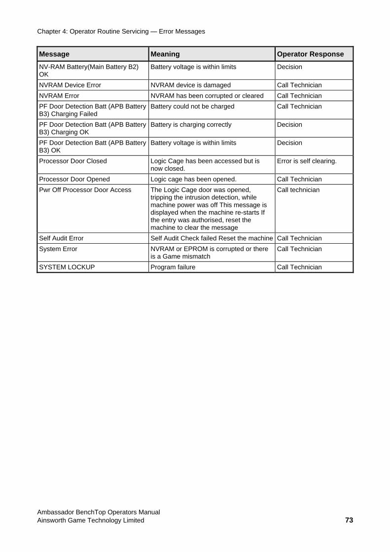
Chapter 4: Operator Routine Servicing — Error Messages
Message Meaning Operator Response
NV-RAM Battery(Main Battery B2)OK
tage is within limits Battery vol Decision
NVRAM Device Error NVRAM device is damaged an Call TechniciNVRAM Error NVRAM has been corrupted or cleared an Call TechniciPF Door Detection Batt (APB Battery B3) Charging Failed
Battery could not be charged Call Technician
PF Door Detection Batt (APB Battery B3) Charging OK
Battery is charging correctly Decision
PF Door Detection Batt (APB Battery B3) OK
its Battery voltage is within lim Decision
Processor Door Closed Logic Cage has been accessed but is ing. now closed.
Error is self clear
Processor Door Opened an Logic cage has been opened. Call TechniciPwr Off Processor Door Access
n, while essage is
rts If
essage
Call technician The Logic Cage door was opened, tripping the intrusion detectiomachine power was off This mdisplayed when the machine re-stathe entry was authorised, reset themachine to clear the m
Self Audit Error Self Audit Check failed Reset the machine an Call TechniciSystem Error NVRAM or EPROM is corrupted or there Technician
is a Game mismatch Call
SYSTEM LOCKUP Program failure Call Technician
Ambassador BenchTop Operators Manual Ainsworth Game Technology Limited 73