Embed Size (px)
Citation preview

R
Operator InterfaceCable Pull Switches
4-2 Visit our website: www.ab.com/catalogs
Overview
?2
4-Emergency StopDevices
4-EmergencyStop Devices
6-
Selection GuideCable Pull Switches Overview
Typical Applications
Mounting Specifications for Extended Length Models
300mm
(11.81in)
2-3m
(6.5-9ft)
75-125m (246-410ft)
Lifeline 4 Cable Grips Steel Cable Tensioner P. Bolts
Tension
Indicator
Reset Knob
E-Stop ButtonTensioner
Notes:
For machinery such as conveyors, it is often more convenient andeffective to use a cable pull device along the hazard area (as shownin the figure below) as the emergency stop device. These devicesuse a steel wire rope connected to latching pull switches so thatpulling on the rope in any direction at any point along its length willtrip the switch to cut off the machine power.
The cable pull switches must detect both a pull on the cable as wellas when the cable goes slack. Slack detection ensures that thecable is not cut and is ready for use.Rockwell Automation developed a unique Lifeline Rope TensionerSystem (LRTS) which helps enable quicker installations.A dedicated stainless steel installation kit must be used with thestainless steel Lifeline 4 instead of the LRTS.
1. The first and last P. bolt/eye bolt must be located as close as possible to the switch eyelet while maintaining adequate clearance (125mm/5 in) from the cable grips to allow free movement. This provides for a straight and efficient pulling action on the switches.2. Additional P. bolts/eye bolts, spaced 2-3 m (6-9 ft) apart, help keep the perpendicular pull force, F, and distance, d, within IEC60947-5-5specifications of 200 N (45 lbs) and 400 mm (15.75 in).3. We recommend using a switch at both cable ends, especially in applications with long cable runs or cable runs going around bends. Thishelps ensure that the safety function is fulfilled upon actuation of the cable in any direction.4. ISO 13850 (EN 418) requires that the full length of cable to be within view when the reset is turned to the run position or the machine mustbe inspected over the whole length of the cable, both before and after resetting.5. On shorter cable runs (max 10 m), a Lifeline tensioner spring may be used at one end of the span. The installation must be such that theabove requirements can be met. When a spring is used, the last P. Bolt/eye bolt must be located as close as possible to the spring whilemaintaining adequate clearance (125 mm/5 in) from the cable grips to allow free movement. This is intended to help to ensure that a pullnear the end of the cable will be between P. Bolts/eye bolts. This should result in operation of the switch contacts instead of only thespring moving.6. Careful attention is required for the design of the installation to ensure that the cable is not likely to become trapped or snagged. This isespecially important when using a tensioner spring because a cable snag between the location of the pull and the switch could prevent theactuation of the safety function.7. It is essential that when the installation is complete, a thorough functional test is made. This should include checking all types anddirections of pull over the length of the cable as well as checking for slack-cable tripping.
Description Lifeline 3 Lifeline 4 Stainless SteelLifeline 4Material Painted Zinc Alloy Painted AluminumAlloy Stainless Steel316Reset Yes Yes Yes
E-Stop No Yes YesCable Span 30 m (98.42 ft) 75 m (246 ft)125 m (410 ft)extended model 75 m (246 ft)

Operator InterfaceCable Pull Switches
4-3Visit our website: www.ab.com/catalogs
Overview
?1-
24-E
mergen
cy Stop
Devices
4-Emer
gency
Stop D
evices
6-
R
Mounting Specifications
L1 L2Lifeline 4 300 mm(11.81 in) 75 m (246 ft)Lifeline 3 125 mm (5 in) 30 m (98 ft)
Mounting Specifications with Spring Tensioner
L1 L2Lifeline 4 300 mm(11.81 in) 20 m (65 ft)Lifeline 3 125 mm (5 in) 10 m (32 ft)
Wall
Lifeline Tensioner
Spring (SS)
Rope Grips
(SS)
Polypropylene
Covered
Steel RopeTensioner
(SS)
Eye Bolts
(SS)
≤10 m (32 ft)Indicator
Tension
300
(11.81)2-3 m (6.5-9 ft)
Stainless Steel
Lifeline 4Thimble
(SS)
Lifeline 3
L12-3m(6-9ft)
d
F
≤ L2
Lifeline 4
Cable Grips
Polypropylene-covered
steel cable
TensionerP. Bolts
Tension
Indicator Reset Knob
E-Stop Button
Reset Knob
Tension
Indicator
Lifeline 3
TensionerSpring
Wall2-3m(6-9ft)
d
F
≤L2
Tensioner
Lifeline 4
Tension
Indicator
Tension
IndicatorL1
Rope Grips
Polypropylene
Covered
Steel Rope Tensioner Eye Bolts
75 m (246 ft)
Reset Knob
E-Stop
Button
Indicator
Tension
300
(11.81)2-3 m (6.5-9 ft)
Stainless Steel
Lifeline 4 Thimble

R
Operator InterfaceCable Pull Switches
4-4 Visit our website: www.ab.com/catalogs
Lifeline Rope Tensioner System (LRTS)
?2
4-Emergency StopDevices
4-EmergencyStop Devices
6-
DescriptionThe LRTS is a unique cable (rope) tensioning system which enablesquicker installation of cable actuated systems. Other methods aretraditionally time consuming and sometimes awkward to fit.Features of the system include:1. Cable adjustment up to 300 mm (11.8 in) (150 mm (5.9 in) eitherside of tensioner)2. Quick thread and grip of cable with cable grip3. Cable tidy incorporated into the cable grips4. Simple tensioning via the tensioner with allen key.Due to the appeal of quick installation and universal use, the LRTScan also be used for applications other than cable actuatedemergency stop systems.Features
Specifications
Four Steps to Install
Thread rope grip 1
Thread rope grip 2
Thread eyebolts & tensioner
Tension system
Unique cable grip system Can be installed and commissioned in approximately 3 minutes Ease of installation, no specialty tools required Up to 300 mm (11.8 in) of cable adjustment Cable tidy incorporated into cable grips
MaterialTensioner: Glass filled nylonCable gripper: Acetal, zinc alloy, stainless steelCable gripper gears: Stainless steelCable: Cable to BS 302:1987, wire Ø4.0Steel Core with polypropylene sheathP. Bolt: Stainless steel
ColorTensioner: YellowCable gripper: Yellow/naturalCable: RedP. Bolt: Natural
Weight—g (lbs) Tensioner: 140 (0.31) Cable gripper: 80 (0.17)Operating Temperature—C (F) -25…80° (-13…176°)Cable O.D. 4 mm (0.15 in)Cable Adjustment Range,Max. 300 mm (11.8 in)Tensioner Holding Force,Max. 500 N (112.5 lb)Gripper Holding Force,Max. 280 N (63.0 lb)Enclosure Type Rating IP30Tensioner Adjustment Tool 5 mm A/F Allen key
R
Operator InterfaceCable Pull Switches
4-5Visit our website: www.ab.com/catalogs
Lifeline Rope Tensioner System (LRTS)
?1-
24-E
mergen
cy Stop
Devices
4-Emer
gency
Stop D
evices
6-
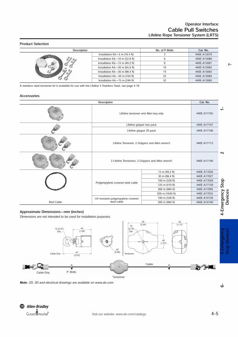
Product Selection
Approximate Dimensions—mm (inches)Dimensions are not intended to be used for installation purposes.
Accessories
Note: 2D, 3D and electrical drawings are available on www.ab.com.
12 (0.47)
Dia.
67
(2.63)
25
(0.98)
70
(2.75)
Dia.
90
(3.54)
43
(1.69)
40
(1.57)
45
(1.77)
TensionerCable Grip
Description No. of P-Bolts Cat. No.Installation Kit—5 m (16.4 ft) 3 440E-A13079Installation Kit—10 m (32.8 ft) 6 440E-A13080Installation Kit—15 m (49.2 ft) 8 440E-A13081Installation Kit—20 m (65.6 ft) 10 440E-A13082Installation Kit—30 m (98.4 ft) 14 440E-A13083Installation Kit—50 m (164 ft) 22 440E-A13084Installation Kit—75 m (246 ft) 32 440E-A13085
A stainless steel tensioner kit is available for use with the Lifeline 4 Stainless Steel, see page 4-18.
Description Cat. No.
Lifeline tensioner and Allen key only 440E-A17105
Lifeline gripper two pack 440E-A17107Lifeline gripper 20 pack 440E-A17106
Lifeline Tensioner, 2 Grippers and Allen wrench 440E-A17112
2 Lifeline Tensioners, 2 Grippers and Allen wrench 440E-A17140
Polypropylene covered steel cable
15 m (49.2 ft) 440E-A1702630 m (98.4 ft) 440E-A17027100 m (328 ft) 440E-A17028125 m (410 ft) 440E-A17129300 m (984 ft) 440E-A17095500 m (1640 ft) 440E-A17032
UV resistant polypropylene coveredsteel cable 100 m (328 ft) 440E-A14739Red Cable 300 m (984 ft) 440E-A14740
Tensioner
Cable Grip P. Bolts
Cable

R
Operator InterfaceCable Pull Switches
4-6 Visit our website: www.ab.com/catalogs
Lifeline 3
?2
4-Emergency StopDevices
4-EmergencyStop Devices
6-
Description
Features
Specifications
The Lifeline 3 is a cable (rope) operated emergency stop devicedesigned to meet the stringent requirements of ISO 13850 (EN 418)(Safety of Machinery—Emergency Stop Equipment). The Lifeline 3system can be installed along or around awkward machinery suchas conveyors and provides a constant-access emergency-stopfacility.
Switches up to 30 m (98 ft) span Universal mounting and operation Switch lockout on cable pulled and cable slack Cable-status indicator on switch lid Industry standard fixing centers to DIN/EN 50041 Quick disconnect styles available
1. The positive-mode mechanism helps ensure that the contacts areimmediately latched open on actuation and can only be reset bythe intentional action of turning the blue reset knob. The designalso protects against nuisance tripping and the effects of thermalexpansion.2. The cable-status indicator makes the system easy to set up andmaintain for spans up to 30 m (98 ft).3. Four sets of contacts are provided: 2 N.C. + 2 N.O., or 3 N.C. +1 N.O. contacts.4. Sealed to IP 67 with rugged construction using die-cast alloy andstainless steel to withstand harsh conditions.
Safety RatingsStandards EN 418, ISO 13850, EN ISO 12100,IEC 60947-5-1, IEC 60947-5-5
Safety ClassificationCat. 1 device per EN 954-1May be suitable for use in Cat 3 orCat 4 systems depending on thearchitecture and applicationcharacteristics
Functional Safety Data Note: For up-to-date information,visit http://www.ab.com/Safety/
B10d: > 2 x 10⁶ operations at min.loadPFHD: < 3 x10⁻⁷MTTFd: > 385 yearsMay be suitable for use inperformance levels Ple or Pld systems(according to ISO 13849-1:2006) andfor use in SIL2 or SIL3 systems(according to IEC 62061) dependingon the architecture and applicationcharacteristicsCertifications CE marked for all applicabledirectives, cULus, TÜV, and CCCOutputsSafety Contacts ! 2 N.C. direct-opening action 3 N.C. direct-opening actionAuxiliary Contacts 2 N.O. direct-opening action 1 N.O. direct-opening actionThermal CurrentIlth 10 ARated Insulation Voltage (Ui) 500VSwitching Current @ Voltage, Min. 5 mA @ 5V DCUtilization CategoryA600/AC-15 (Ue) 600V 500V 240V 120V
(le) 1.2 A 1.4 A 3 A 6 AN600/DC-13 (Ue) 600V 500V 250V 120V
(le) 0.4 A 0.55 A 1.1 A 2.2 AOperating CharacteristicsCable Span Between Switches, Max. 30 m (98.42 ft)Tensioning Force to Run Position 103 N (23.17 lbs) typicalTensioning Force to Lockout 188 N (42.3 lbs) typicalOperating Force, Min. <125 N (28.1 lb) at 300 mm deflectionActuation Frequency, Max. 1 cycle per secOperating Life @ 100 mA load 1 x 10⁶EnvironmentalEnclosure Type Rating IP 67Operating Temperature—C (F) -25…80° (-13…176°)Physical CharacteristicsHousing Material Heavy-Duty Painted Zinc-Based Die-Cast AlloyIndicator Material Glass Filled NylonEye Nut Material Stainless SteelWeight—g (lbs) 610 (1.34)Color Yellow body, blue reset button Usable for ISO 13849-1:2006 and IEC 62061. Data is based on the B10dvalue given and:- Usage rate of 1op/10 mins., 24 hrs/day, 360 days/year, representing 51840 operations per year- Mission time/Proof test interval of 38 years! The safety contacts are described as normally closed (N.C.) i.e., with theguard closed, actuator in place (where relevant) and the machine able to bestarted.Note: It is recommended that the LRTS (Lifeline Rope Tensioning System)should be used with the Lifeline 3 cable rope switch.

R
Operator InterfaceCable Pull Switches
4-7Visit our website: www.ab.com/catalogs
Lifeline 3
?1-
24-E
mergen
cy Stop
Devices
4-Emer
gency
Stop D
evices
6-
Product Selection
Recommended Logic Interfaces
Connection SystemsDescription 5-Pin Micro(M12)" 8-Pin Micro(M12) 12-Pin M23
Cordset — 889D-F8AB-§ 889M-F12AH-§Patchcord 889D-F5ACDM-♣ 889D-F8ABDM-♣ 889M-F12AMMU-!
Description Safety Outputs Auxiliary Outputs Terminals Reset Type Power Supply Cat. Page No. Cat. No.Single-Function Safety Relays for 2 N.C. Contact SwitchMSR127RP 3 N.O. 1 N.C. Removable (Screw) Monitored Manual 24V AC/DC 5-24 440R-N23135MSR127TP 3 N.O. 1 N.C. Removable (Screw) Auto./Manual 24V AC/DC 5-24 440R-N23132MSR126T 2 N.O. None Fixed Auto./Manual 24V AC/DC 5-22 440R-N23117MSR30RT 2 N.O. Solid State 1 N.O. Solid State Removable Auto./Manual orMonitored Manual 24V DC 5-16 440R-N23198Modular Safety RelaysMSR210P Base2 N.C. only 2 N.O. 1 N.C. and 2 PNPSolid State Removable Auto./Manual orMonitored Manual 24V DC from thebase unit 5-74 440R-H23176MSR220P InputModule — — Removable — 24V DC 5-78 440R-H23178MSR310P Base MSR300 SeriesOutput Modules 3 PNP Solid State Removable Auto./ManualMonitored Manual 24V DC 5-94 440R-W23219MSR320P InputModule — 2 PNP Solid State Removable — 24V DC from thebase unit 5-98 440R-W23218
Note: For additional Safety Relays connectivity, see the Safety Relays section (page 5-8) of this catalog.For additional Safety I/O and Safety PLC connectivity, see the Programmable Safety System section (page 5-107) of this catalog.For application and wiring diagrams, see the Safety Applications section (page 10-1) of this catalog.
§ Replace symbol with 2 (2 m), 5 (5 m), or 10 (10 m) for standard cable lengths.♣ Replace symbol with 1 (1 m), 2 (2 m), 3 (3 m), 5 (5 m), or 10 (10 m) for standard cable lengths.! Replace symbol with 0M3 (0.3 m), 0M6 (0.6 m), 1 (1 m), 2 (2 m) or 3 (3 m) for standard lengths."To connect to ArmorBlock Guard I/O.
Contacts Cat. No.
Safety Auxiliary
Conduits Connectors
M20 1/2 inch NPT 12-Pin M23 8-Pin Micro (M12)!Connect to ArmorBlockGuard I/O5-Pin Micro (M12)‡
2 N.C. 2 N.O. 440E-D13118 440E-D13120 440E-D13132 440E-D21BNYH 440E-D2NNNYS3 N.C. 1 N.O. 440E-D13112 440E-D13114 440E-D13124 — —
For connector ratings, see page 3-9.! With an 8-pin micro (M12) connector, not all contacts are connected. See Typical Wiring Diagram on page 4-9 for wiring details.‡ For connection to ArmorBlock Guard I/O. With a 5-pin micro (M12) connector, not all contacts are connected. See Typical Wiring Diagram on page 4-9 forwiring details.

R
Operator InterfaceCable Pull Switches
4-8 Visit our website: www.ab.com/catalogs
Lifeline 3
?2
4-Emergency StopDevices
4-EmergencyStop Decvices
6-
Accessories
Approximate Dimensions—mm (inches)Dimensions are not intended to be used for installation purposes.
4 x M5 mounting holes
56
(2.2)
43
(1.69)
10.5
(0.41)
204 (8.03)
60 (2.36)
40
(1.57
30
(1.18)
Description Cat. No.Lifeline P. BoltM8 x 1.25 thread size, 58 mm (2.28 in.)threaded length, 12 mm (0.47 in.) dia. eye,95 mm (3.74 in.) overall length
440E-A17003Lifeline Tensioner Spring19 mm (0.75 in) diameter, 210 mm (8.27 in)overall length, 50 N force 440E-A13078
Lifeline inside corner pulleyInternal diameter 16 mm (0.64 in) zinc-plated mild steel 440A-A17101
Lifeline Outside Corner PulleyOutside diameter 38 mm (1.5 in) zinc-plated mild steel 440A-A17102
Blanking Plug, M20 Conduit 440A-A07265
Cable Grip, M20 Conduit, accommodatescable diameter 7…10.5 mm (0.41…0.27 in) 440A-A09028
Adaptor, Conduit, M20 to 1/2 inch NPT,Plastic 440A-A09042
Screwdriver Including Security Bit 440A-A09018
Note: 2D, 3D and electrical drawings are available on www.ab.com.

Operator InterfaceCable Pull Switches
4-9Visit our website: www.ab.com/catalogs
Lifeline 3
?1-
24-E
mergen
cy Stop
Devices
5-Seelc
tion Cri
teria6-
4-Emer
gency
Stop D
evices
6-
R
Typical Wiring DiagramsDescription 2 N.C. & 2 N.O. 3 N.C. & 1 N.O.
Contact Configuration1211 Safety A
2221 Safety B
3433 Aux A
4443 Aux B
Safety C
Aux A
12 11 Safety A
22 21 Safety B
32 31
44 43
Contact ActionSafety A
Safety B
Aux A
Aux B
Cable Slack Lockout
Cable TensionRange
Cable PulledLockout
3.50 mm 6 9 12.5 13.5
Safety A
Safety B
Safety C
Aux B
Cable SlackLockout
Cable TensionRange
Cable PulledLockout
30 mm 6 9 10.5 13.5
Open Closed
5-Pin Micro (M12)for ArmorBlock Guard I/O5-Safety B
4-Safety B3-NA
1-Safety A
2-Safety A
—
8-Pin Micro (M12)5-Safety A
6-Safety B7-Aux A
8-Safety A
4-Safety B
3-Ground
1-Aux A
2-N/A
—
12-Pin M23 1-3 Safety A Safety A
2
3
45
6
1
11
10
98
712
4-6 Safety B Safety B7-8 Aux A Safety C
9-10 Aux B Aux A
Pins 2, 5, 11not connected 12 Ground Ground
8-Pin Cordset889D-F8AB-
GreyRed Safety AYellowPink Safety BWhiteBlue Aux AGreen GroundBrown Not Used
12-Pin Cordset889M-F12X9AE-!
BrownBlue Safety A Safety AWhiteGreen Safety B Safety BYellowGrey Aux A Safety CPinkRed Aux B Aux A
GreenYellow Ground Ground Replace symbol with 2 (2 m), 5 (5 m), or 10 (10 m) for standard cable lengths.! Replace symbol with 0F5 (0.5 ft) or 1F (1 ft) for standard cable lengths.

R
Operator InterfaceCable Pull Switches
4-10 Visit our website: www.ab.com/catalogs
Lifeline 4
?2
4-Emergency StopDevices
4-EmergencyStop Devices
6-
DescriptionThe Lifeline 4 cable/push button operated system can be installedalong or around awkward machinery such as conveyors and providea constant emergency stop access.The Lifeline 4 is the only device of its kind to incorporate thefollowing features in one unit making it the most versatile cableswitch on the market.
Features
Specifications
Lid mounted E-Stop button Cable status indicator on lidA mushroom head emergency stopbutton is included on the unit toprovide total E-Stop access even atthe extreme ends of the span.The cable status indicator makesthe system easy to setup andmaintain for spans up to 125meters.
Switches up to 125 meter span Universal mounting and operation Lid mounted emergency stop button, designed to conform toEN 418 Switch lockout on cable pulled and cable slack Cable status indicator on switch lid
1. The positive mode mechanism helps ensure that the contacts areimmediately latched open on actuation and can only be reset bythe intentional action of turning the blue reset knob. The designalso protects against nuisance tripping and the effects of thermalexpansion.2. A mushroom head emergency stop button is included on the unitto provide E-Stop access even at the extreme ends of the span.3. The cable status indicator makes the system easy to set up andmaintain for spans up to 125 meters.4. Four sets of contacts are provided: 2 N.C. + 2 N.O. or 3 N.O. +1 N.O. contacts5. Sealed to IP 66 with rugged construction using die-cast alloy andstainless steel to withstand harsh conditions.
Safety RatingsStandards EN 418, ISO 13850, EN ISO 12100,IEC 60947-5-1, IEC 60947-5-5
Safety ClassificationCat. 1 device per EN 954-1May be suitable for use in Cat 3 orCat 4 systems depending on thearchitecture and applicationcharacteristics
Functional Safety Data Note: For up-to-date information,visit http://www.ab.com/Safety/
B10d: > 2 x 10⁶ operations at min.loadPFHD: < 3 x10⁻⁷MTTFd: > 385 yearsMay be suitable for use inperformance levels Ple or Pld systems(according to ISO 13849-1:2006) andfor use in SIL2 or SIL3 systems(according to IEC 62061) dependingon the architecture and applicationcharacteristicsCertifications CE marked for all applicabledirectives, cULus, TÜV, and CCCOutputsSafety Contacts ! 2 N.C. direct-opening action 3 N.C. direct-opening actionAuxiliary Contacts 2 N.O. direct-opening action 1 N.O. direct-opening actionThermal CurrentIlth 10 ARated Insulation Voltage (Ui) 500VSwitching Current @ Voltage, Min. 5 mA @ 5V DCUtilization CategoryA600/AC-15 (Ue) 600V 500V 240V 120V
(le) 1.2 A 1.4 A 3 A 6 AN600/DC-13 (Ue) 600V 500V 250V 120V
(le) 0.4 A 0.55 A 1.1 A 2.2 AOperating CharacteristicsCable Span Between Switches, Max. 75 m (246 ft) standard model and75…125 m (146…410 ft) extendedlength modelTensioning Force to Run Position 103 N (23.17 lbs) typicalTensioning Force to Lockout 188 N (42.3 lbs) typicalOperating Force, Min. <125 N (28.1 lbs) at 300 mmdeflectionActuation Frequency, Max. 1 cycle per secOperating Life @ 100 mA load 1 x 10⁶EnvironmentalEnclosure Type Rating IP 67Operating Temperature—C (F) -25…+80° (-13…+176°)Physical CharacteristicsHousing Material Heavy-Duty Painted Zinc-Based Die-Cast Alloy (LM24)Indicator Material Glass Filled NylonEye Nut Material Stainless SteelWeight—g (lbs) 630 (1.38)Color Yellow Body, Blue Reset Button Usable for ISO 13849-1:2006 and IEC 62061. Data is based on the B10dvalue given and:- Usage rate of 1op/10 mins., 24 hrs/day, 360 days/year, representing 51840 operations per year- Mission time/Proof test interval of 38 years! The safety contacts are described as normally closed (N.C.) i.e., with theguard closed, actuator in place (where relevant) and the machine able to bestarted.Note: It is recommended that the LRTS (Lifeline Rope Tensioning System)should be used with the Lifeline 4 cable rope switch.
R
Operator InterfaceCable Pull Switches
4-11Visit our website: www.ab.com/catalogs
Lifeline 4
?1-
24-E
mergen
cy Stop
Devices
4-Emer
gency
Stop D
evices
6-
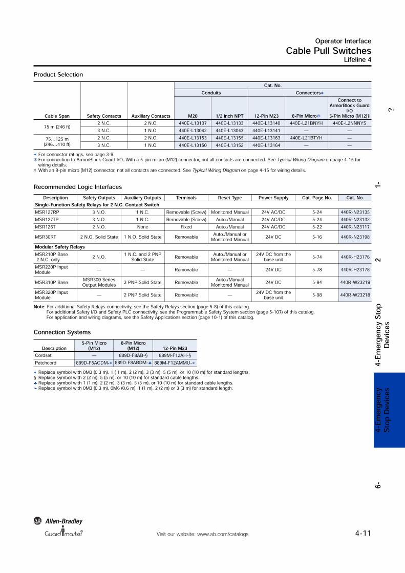
Product Selection
Recommended Logic Interfaces
Connection SystemsDescription 5-Pin Micro(M12) 8-Pin Micro(M12) 12-Pin M23
Cordset — 889D-F8AB-§ 889M-F12AH-§Patchcord 889D-F5ACDM- 889D-F8ABDM-♣ 889M-F12AMMU-!
Description Safety Outputs Auxiliary Outputs Terminals Reset Type Power Supply Cat. Page No. Cat. No.Single-Function Safety Relays for 2 N.C. Contact SwitchMSR127RP 3 N.O. 1 N.C. Removable (Screw) Monitored Manual 24V AC/DC 5-24 440R-N23135MSR127TP 3 N.O. 1 N.C. Removable (Screw) Auto./Manual 24V AC/DC 5-24 440R-N23132MSR126T 2 N.O. None Fixed Auto./Manual 24V AC/DC 5-22 440R-N23117MSR30RT 2 N.O. Solid State 1 N.O. Solid State Removable Auto./Manual orMonitored Manual 24V DC 5-16 440R-N23198Modular Safety RelaysMSR210P Base2 N.C. only 2 N.O. 1 N.C. and 2 PNPSolid State Removable Auto./Manual orMonitored Manual 24V DC from thebase unit 5-74 440R-H23176MSR220P InputModule — — Removable — 24V DC 5-78 440R-H23178MSR310P Base MSR300 SeriesOutput Modules 3 PNP Solid State Removable Auto./ManualMonitored Manual 24V DC 5-94 440R-W23219MSR320P InputModule — 2 PNP Solid State Removable — 24V DC from thebase unit 5-98 440R-W23218
Note: For additional Safety Relays connectivity, see the Safety Relays section (page 5-8) of this catalog.For additional Safety I/O and Safety PLC connectivity, see the Programmable Safety System section (page 5-107) of this catalog.For application and wiring diagrams, see the Safety Applications section (page 10-1) of this catalog.
Replace symbol with 0M3 (0.3 m), 1 ( 1 m), 2 (2 m), 3 (3 m), 5 (5 m), or 10 (10 m) for standard lengths.§ Replace symbol with 2 (2 m), 5 (5 m), or 10 (10 m) for standard cable lengths.♣ Replace symbol with 1 (1 m), 2 (2 m), 3 (3 m), 5 (5 m), or 10 (10 m) for standard cable lengths.! Replace symbol with 0M3 (0.3 m), 0M6 (0.6 m), 1 (1 m), 2 (2 m) or 3 (3 m) for standard length.
Cable Span Safety Contacts Auxiliary Contacts
Cat. No.Conduits Connectors
M20 1/2 inch NPT 12-Pin M23 8-Pin Micro!Connect toArmorBlock GuardI/O5-Pin Micro (M12)‡
75 m (246 ft) 2 N.C. 2 N.O. 440E-L13137 440E-L13133 440E-L13140 440E-L21BNYH 440E-L2NNNYS3 N.C. 1 N.O. 440E-L13042 440E-L13043 440E-L13141 — —
75…125 m(246…410 ft) 2 N.C. 2 N.O. 440E-L13153 440E-L13155 440E-L13163 440E-L21BTYH —3 N.C. 1 N.O. 440E-L13150 440E-L13152 440E-L13164 — —
For connector ratings, see page 3-9.! For connection to ArmorBlock Guard I/O. With a 5-pin micro (M12) connector, not all contacts are connected. See Typical Wiring Diagram on page 4-15 forwiring details.‡ With an 8-pin micro (M12) connector, not all contacts are connected. See Typical Wiring Diagram on page 4-15 for wiring details.

R
Operator InterfaceCable Pull Switches
4-12 Visit our website: www.ab.com/catalogs
Lifeline 4
?2
4-Emergency StopDevices
4-EmergencyStop Devices
6-
AccessoriesDescription Cat. No.
Lifeline P. Bolt 440E-A17003
Lifeline Tensioner Spring 440E-A13078
Replacement cover for Lifeline 4 cable/push button 440E-A13054
Replacement cover for Lifeline 4 cable/push button, no E-Stop 440E-A17115
Lifeline inside corner pulley 440A-A17101
Lifeline Outside Corner Pulley 440A-A17102
Mounting Bracket for Lifeline 4 cable/push button 440E-A17130
Blanking Plug, M20 Conduit 440A-A07265
Cable Grip, M20 Conduit, accommodates cable diameter 7…10.5mm (0.41…0.27 in) 440A-A09028
Adaptor, Conduit, M20 to 1/2 inch NPT, Plastic 440A-A09042
Screwdriver Including Security Bit 440A-A09018
Operator InterfaceCable Pull Switches
4-13Visit our website: www.ab.com/catalogs
Lifeline 4
?1-
24-E
mergen
cy Stop
Devices
5-Seelc
tion Cri
teria6-
4-Emer
gency
Stop D
evices
6-
R
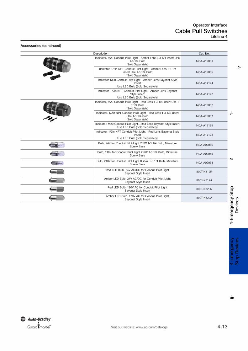
Accessories (continued)Description Cat. No.
Indicator, M20 Conduit Pilot Light—Amber Lens T-3 1/4 Insert UseT-3 1/4 Bulb(Sold Separately) 440A-A19001Indicator, 1/2in NPT Conduit Pilot Light—Amber Lens T-3 1/4Insert Use T-3 1/4 Bulb(Sold Separately) 440A-A19005
Indicator, M20 Conduit Pilot Light—Amber Lens Bayonet StyleInsertUse LED Bulb (Sold Separately) 440A-A17124Indicator, 1/2in NPT Conduit Pilot Light—Amber Lens BayonetStyle InsertUse LED Bulb (Sold Separately) 440A-A17122
Indicator, M20 Conduit Pilot Light—Red Lens T-3 1/4 Insert Use T-3 1/4 Bulb(Sold Separately) 440A-A19002Indicator, 1/2in NPT Conduit Pilot Light—Red Lens T-3 1/4 InsertUse T-3 1/4 Bulb(Sold Separately) 440A-A19007
Indicator, M20 Conduit Pilot Light—Red Lens Bayonet Style InsertUse LED Bulb (Sold Separately) 440A-A17125Indicator, 1/2in NPT Conduit Pilot Light—Red Lens Bayonet StyleInsertUse LED Bulb (Sold Separately) 440A-A17123
Bulb, 24V for Conduit Pilot Light 2.8W T-3 1/4 Bulb, MiniatureScrew Base 440A-A09056Bulb, 110V for Conduit Pilot Light 2.6W T-3 1/4 Bulb, MiniatureScrew Base 440A-A09055
Bulb, 240V for Conduit Pilot Light 0.75W T-3 1/4 Bulb, MiniatureScrew Base 440A-A09054Red LED Bulb, 24V AC/DC for Conduit Pilot LightBayonet Style Insert 800T-N319R
Amber LED Bulb, 24V AC/DC for Conduit Pilot LightBayonet Style Insert 800T-N319ARed LED Bulb, 120V AC for Conduit Pilot LightBayonet Style Insert 800T-N320R
Amber LED Bulb, 120V AC for Conduit Pilot LightBayonet Style Insert 800T-N320A

R
Operator InterfaceCable Pull Switches
4-14 Visit our website: www.ab.com/catalogs
Lifeline 4
?2
4-Emergency StopDevices
4-EmergencyStop Devices
6-
Approximate Dimensions—mm (inches)Dimensions are not intended to be used for installation purposes. Standard Model
Extended Length Models (75 to 125 m cable span)
Note: 2D, 3D and electrical drawings are available on www.ab.com.
85 (
3.35
)
51 (
2.0)
81 (3.19)min.
94.5 (3.72)max 115 (4.53)
101 (3.98)
48 (
1.89
)
62 (
2.44
)
51 (2.0)
85 (3.35)
Reset Button
Emergency Stop Button
4 Mounting Holes
Clearance for M5 Screws 101 (3.98)
7.0
(0.28)
48
(1
.89
)
62
(2.4
4)
101 (3.98) min. to
114.5 (4.51) max.
51
(2
.01
)
85 (3.35)
10.5
(0.41)115 (4.53)
37 (1.46)
25.5
(1.0)

Operator InterfaceCable Pull Switches
4-15Visit our website: www.ab.com/catalogs
Lifeline 4
?1-
24-E
mergen
cy Stop
Devices
5-Seelc
tion Cri
teria6-
4-Emer
gency
Stop D
evices
6-
R
Typical Wiring DiagramsDescription 2 N.C. & 2 N.O. 3 N.C. & 1 N.O.
Contact Configuration
33 34
11 12
21 22
43 44
Safety A
Safety B
Aux A
Aux B 31 32
11 12
21 22
43 44
Safety A
Safety B
Safety C
Aux B
Contact ActionSafety A
Safety B
Aux A
Aux B
Cable Slack Lockout
Cable TensionRange
Cable PulledLockout
3.50 mm 6 9 12.5 13.5
Safety A
Safety B
Safety C
Aux B
Cable SlackLockout
Cable TensionRange
Cable PulledLockout
30 mm 6 9 10.5 13.5
Open Closed
8-Pin Micro (M12)5-Safety A
6-Safety B7-Aux A
8-Safety A
4-Safety B
3-Ground
1-Aux A
2-N/A
—
12-Pin M23 1-3 Safety A Safety A
2
3
45
6
1
11
10
98
712
4-6 Safety B Safety B7-8 Aux A Safety C
9-10 Aux B Aux A
Pins 2, 5, 11not connected 12 Ground Ground
5-Pin Microfor ArmorBlock Guard I/O5-Safety B
4-Safety B3-NA
1-Safety A
2-Safety A
—
8-Pin Cordset889D-F8AB-
GreyRed Safety A —YellowPink Safety B —WhiteBlue Aux A —Green Ground —Brown Not Used
12-Pin Cordset889M-F12X9AE-
BrownBlue Safety A Safety AWhiteGreen Safety B Safety BYellowGrey Aux A Safety CPinkRed Aux B Aux A
GreenYellow Ground Ground Replace symbol with 2 (2 m), 5 (5 m), or 10 (10 m) for standard cable lengths. Replace symbol with 0F5 (0.5 ft) or 1F (1 ft) for standard cable lengths.

R
Operator InterfaceCable Pull Switches
4-16 Visit our website: www.ab.com/catalogs
Lifeline 4 Stainless Steel
?2
4-Emergency StopDevices
4-EmergencyStop Devices
6-
DescriptionThe stainless steel Lifeline 4 cable/push button operated systemcan be installed along or around awkward machinery such asconveyors and provide a constant emergency stop access. Thisswitch is made from stainless steel 316 and is suitable for externaluse, applications where there are hygiene requirements and othersituations where a level of corrosion resistance is required.The Lifeline 4 is the only device of its kind to incorporate thefollowing features in one unit making it the most versatile cableswitch on the market.
Features
Specifications
Lid mounted E-Stop buttonA mushroom head emergency stopbutton is included on the unit toprovide total E-Stop access even atthe extreme ends of the span.
Cable status indicator on lidThe cable status indicator makesthe system easy to setup andmaintain for spans up to 75 m(246 ft).
! Switches up to 75 m (246 ft) span! Universal mounting and operation! Lid mounted emergency stop button, designed to conform toEN–418! Switch lockout on cable pulled and cable slack! Cable status indicator on switch lid! Made from stainless steel 316
1. The positive mode mechanism helps ensure that the contacts areimmediately latched open on actuation and can only be reset bythe intentional action of turning the blue reset knob. The designalso protects against nuisance tripping and the effects of thermalexpansion.2. A mushroom head emergency stop button is included on the unitto provide E-Stop access even at the extreme ends of the span.3. The cable status indicator makes the system easy to set up andmaintain for spans up to 75 meters.4. Four sets of contacts are provided: 2 N.C. + 2 N.O.5. Sealed to IP 66 and IP 69K with rugged construction usingstainless steel 316 to withstand harsh conditions.
Safety RatingsStandards EN 60947-5-5, ISO 13850, EN ISO12100, IEC 60947-5-1, EN 418
Safety ClassificationCat. 1 device per EN 954-1May be suitable for use in Cat 3 orCat 4 systems depending on thearchitecture and applicationcharacteristics
Functional Safety Data Note: For up-to-date information,visit http://www.ab.com/Safety/
B10d: > 2 x 10⁶ operations at min.loadPFHD: < 3 x10⁻⁷MTTFd: > 385 yearsMay be suitable for use inperformance levels Ple or Pld systems(according to ISO 13849-1:2006) andfor use in SIL2 or SIL3 systems(according to IEC 62061) dependingon the architecture and applicationcharacteristicsCertifications CE marked for all applicabledirectives, cULus certified and TÜVOutputsSafety Contacts 2 N.C. direct opening actionAuxiliary Contacts 2 N.O.Thermal CurrentIlth 10 ARated Insulation Voltage (Ui) 500VSwitching Current @ Voltage, Min. 5 mA @ 5V DCUtilization CategoryA600/AC-15 (Ue) 600V 500V 240V 120V
(le) 1.2 A 1.4 A 3 A 6 AN600/DC-13 (Ue) 600V 500V 250V 125V
(le) 0.4 A 0.55 A 1.1 A 2.2 AOperating CharacteristicsCable Span Between Switches, Max. 75 m (246 ft)Tensioning Force to Run Position 103 N (23.17 lbs) typicalTensioning Force to Lockout 188 N (42.3 lbs) typicalOperating Force, Min. <125 N (300 mm deflection; 28.1 lbdeflection)Actuation Frequency, Max. 1 Cycle per secOperating Life @ 100 mA load 1 x 10⁶EnvironmentalEnclosure Type Rating IP 66, IP 67, IP 69KOperating Temperature—C (F) -25…80° (-13…176°)Physical CharacteristicsHousing Material Stainless Steel 316Indicator Material AcetalEye Nut Material Stainless SteelWeight—g (lbs) 1442 (3.17)Color Unpainted metal Usable for ISO 13849-1:2006 and IEC 62061. Data is based on the B10dvalue given and:- Usage rate of 1op/10 mins., 24 hrs/day, 360 days/year, representing 51840 operations per year- Mission time/Proof test interval of 38 years The safety contacts are described as normally closed (N.C.) i.e., with theguard closed, actuator in place (where relevant) and the machine able to bestarted.Note: It is recommended that the stainless steel installation kit should beused with the stainless steel Lifeline 4 as it is made of suitablematerials for harsh conditions.

R
Operator InterfaceCable Pull Switches
4-17Visit our website: www.ab.com/catalogs
Lifeline 4 Stainless Steel
?1-
24-E
mergen
cy Stop
Devices
4-Emer
gency
Stop D
evices
6-
Product Selection
Recommended Logic Interfaces
Connection Systems
Replace symbol with 2 (2 m), 5 (5 m), or 10 (10 m) for standard cable lengths. Replace symbol with 0M3 (0.3 m), 0M6 (0.6 m), 1 (1 m), 2 (2 m) or 3 (3 m) for standard length.
Description 12-Pin M23Cordset 889M-F12AH- Patchcord 889M-F12AMMU-
Cable Span Safety Contacts Auxiliary ContactsCat. No.
Conduits Connectors§M20 1/2 inch NPT 12-Pin M23Up to 75 m (246 ft) 2 N.C. 2 N.O. 440E-L22BNSM 440E-L22BNST 440E-L22BNSL
§ For connector ratings, see page 3-9.
Description Safety Outputs Auxiliary Outputs Terminals Reset Type Power Supply Cat. Page No. Cat. No.Single-Function Safety Relays for 2 N.C. Contact SwitchMSR127RP 3 N.O. 1 N.C. Removable (Screw) Monitored Manual 24V AC/DC 5-24 440R-N23135MSR127TP 3 N.O. 1 N.C. Removable (Screw) Auto./Manual 24V AC/DC 5-24 440R-N23132MSR126T 2 N.O. None Fixed Auto./Manual 24V AC/DC 5-22 440R-N23117MSR30RT 2 N.O. Solid State 1 N.O. Solid State Removable Auto./Manual orMonitored Manual 24V DC 5-16 440R-N23198Modular Safety RelaysMSR210P Base2 N.C. only 2 N.O. 1 N.C. and 2 PNPSolid State Removable Auto./Manual orMonitored Manual 24V DC from thebase unit 5-74 440R-H23176MSR220P InputModule — — Removable — 24V DC 5-78 440R-H23178MSR310P Base MSR300 SeriesOutput Modules 3 PNP Solid State Removable Auto./ManualMonitored Manual 24V DC 5-94 440R-W23219MSR320P InputModule — 2 PNP Solid State Removable — 24V DC from thebase unit 5-98 440R-W23218
Note: For additional Safety Relays connectivity, see the Safety Relays section (page 5-8) of this catalog.For additional Safety I/O and Safety PLC connectivity, see the Programmable Safety System section (page 5-107) of this catalog.For application and wiring diagrams, see the Safety Applications section (page 10-1) of this catalog.

R
Operator InterfaceCable Pull Switches
4-18 Visit our website: www.ab.com/catalogs
Lifeline 4 Stainless Steel
?2
4-Emergency StopDevices
4-EmergencyStop Devices
6-
Approximate Dimensions—mm (inches)Dimensions are not intended to be used for installation purposes. Standard Model
Note: 2D, 3D and electrical drawings are available on www.ab.com.
Accessories
Note:Installation Kits include the following parts: 1 rope, 1 turnbuckle tensioner, 4 thimbles, 8 rope grips and eyebolts, nuts and washersdepending on the length of the rope.
Description Eye Bolts Cat. No.Stainless steel installation kit—5 m (16.4 ft) 4 440E-A13194
Stainless steel installation kit—10 m (32.8 ft) 4 440E-A13195Stainless steel installation kit—15 m (49.2 ft) 7 440E-A13196Stainless steel installation kit—20 m (65.6 ft) 8 440E-A13197Stainless steel installation kit—30 m (98.4 ft) 12 440E-A13198Stainless steel installation kit—50 m (164 ft) 20 440E-A13199Stainless steel installation kit—75 m (246 ft) 30 440E-A13200
Stainless steel 304 eyebolt complete M8 x 1.25 thread size, 58 mm (2.28 in) threaded length,12 mm (0.47 in) dia. eye 95 mm (3.74 in) overall length 440E-A13201Stainless steel 316 tensioner spring, 19 mm (0.75 in) dia. 210 mm (8.27 in) overall length 440E-A13202
Replacement Cover 440E-A13203
Replacement cover no E-Stop 440E-A13204
Stainless steel 316 inside corner pulley 440E-A13205Stainless steel outside corner pulley 440E-A13206
85 (
3.35
)
51 (
2.0)
81 (3.19)min.
94.5 (3.72)max 115 (4.53)
101 (3.98)
48 (
1.89
)
62 (
2.44
)

R
Operator InterfaceCable Pull Switches
4-19Visit our website: www.ab.com/catalogs
Lifeline 4 Stainless Steel
?1-
24-E
mergen
cy Stop
Devices
4-Emer
gency
Stop D
evices
6-
Typical Wiring DiagramsDescription 2 N.C. & 2 N.O.
Contact Configuration
33 34
11 12
21 22
43 44
Safety A
Safety B
Aux A
Aux B
Contact ActionSafety A
Safety B
Aux A
Aux B
Cable Slack Lockout
Cable TensionRange
Cable PulledLockout
3.50 mm 6 9 12.5 13.5
Open Closed
12-Pin M23 1-3 Safety A
2
3
45
6
1
11
10
98
712
4-6 Safety B7-8 Aux A
9-10 Aux B
Pins 2, 5, 11not connected 12 Ground
12-Pin Cordset889M-F12X9AE-
BrownBlue Safety AWhiteGreen Safety BYellowGrey Aux APinkRed Aux B
GreenYellow Ground Replace symbol with 0F5 (0.5 ft) or 1F (1 ft) for standard cable lengths.