Embed Size (px)
Citation preview

Push-Pull andE-Stop Switches
Datasheet
2 sensing.honeywell.com
Push-Pull and E-Stop SwitchesHoneywell Push-pull and E-stop switches are durable, environmentally sealed, sliding contact switches incorporating two circuits with multiple combinations. The sliding contacts provide positive contact closure and opening when the switch knob is operated.
The dual O-ring design protects the contact chamber by isolating it from any moisture or any other contaminant. These Push-pull and E-stop switches are available as two-circuit switches. Contact closures are available with both circuits closed in the push position, both circuits closed in the pull position, or alternate closure: one closed and one open.
These switches can be a replacement for sealed and unsealed switches including power take-off switches and park brake switches. These rugged and reliable switches increase application reliability and facilitate seamless equipment operation and control with their ability to keep dirt and moisture out of the contact chamber, thereby promoting longer switch life.
Multiple standard knob colors are available with these switches and can be shipped in bulk packaging.
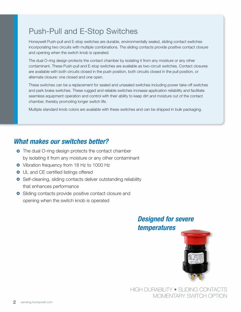
HIGH DURABILITY • SLIDING CONTACTSMOMENTARY SWITCH OPTION
The dual O-ring design protects the contact chamber
by isolating it from any moisture or any other contaminant
Vibration frequency from 18 Hz to 1000 Hz
UL and CE certified listings offered
Self-cleaning, sliding contacts deliver outstanding reliability
that enhances performance
Sliding contacts provide positive contact closure and
opening when the switch knob is operated
What makes our switches better?
Designed for severe temperatures

3sensing.honeywell.com
ENVIRONMENTAL PROTECTIONHoneywell Push-pull and E-stop switches are designed and tested to withstand a wide range of environmental conditions and contaminants: severe temperatures, chemical splashes, pressure wash, vibration, dust, humidity, and salt.
IMPROVED DURABILITYThe dual O-ring design protects the contact chamber by isolating it from moisture and/or any other contaminant.
NON-CONDENSING CAPABILITYThese Push-pull switches can be operated in humidity range of 5 %RH to 95 %RH and are designed for severe temperatures.
SLIDING CONTACTSThe sliding contacts provide positive contact closure and opening when the switch knob is operated.
ENHANCED DURABILITYIP67 sealing (select listings); resistant to impact, vibration, and shock.
MULTIPLE KNOB COLOR AVAILABILITY
UL FILE E219293 (select listings)
Features and Benefits
Form factor! Easily customized for specific applications

4 sensing.honeywell.com
Push-Pull and E-Stop Switches
Honeywell Push-pull and E-stop switches are found in the toughest applications including:
• Construction• Agricultural• Marine• Material handling• Machine tools• Mining• Lawn and garden• Heavy equipment
Potential Applications

5sensing.honeywell.com
Push-Pull and E-Stop Switches
Characteristics Description
Electrical
Nominal voltage 12 dc, 24 dc, 48 dc, or C300*
Current, max. 20 A @ 12 Vdc, 10 A @ 24 Vdc, 4 A @ 48 Vdc
Current, min. 0.1 A, resistive
Dielectric 500 Vdc or 707 Vdc for 1 minute, 5 mA max.
Voltage drop 1 Vdc at rated dc loads, max.
Mechanical
Operating force 27 N ±14 N
Life 25,000 cycles at rated load
Handle shock 1 m [39.37 in] drop to hard surface
Vibration 10 g max., 18 Hz to 1000 Hz
Connector Screw terminals (combo-head), wire harness with 4-pin Deutsch connector
Environmental
Humidity 95 % non-condensing
UV color fade DE 3 max. at 15,000 hours UVB, ASTM G 154-06
TemperatureOperating -40 °C to 40 °C [-40 °F to 104 °F]
Storage -40 °C to 80 °C [-40 °F to 176 °F]
Sealing 50058830-05 is IP67 rated
Approvals UL, CE (select listings)
Table 1. Electrical, Mechanical, and Environmental Specifications
Table 2. Electrical Ratings based on Utilization Categories
Designation1 Utilization Category
Conventional EnclosedThermal
Current Ithe (A)
Rated Operational Current Ie (A) at Rated Operational Voltage
VA Rating
VA
ac — 120 V 240 V 380 V 480 V 500 V 600 V Make Break
C300 AC-15 2,5 1,5 0,75 — — — — 1800 180
Note 1: The letter stands for the conventional enclosed thermal current and identifies (ac or dc): for example B means 5 A ac. The rated insulation voltage Ui is at least equal to the number after the letterNote 2: The rated operational current Ie (A), the rated operational voltage Ue (V) and the break apparent power B (VA) are correlated by the formula B=Ue . le
*For details, please refer Table 2

6 sensing.honeywell.com
Code Quantity/Packaging Fastenings
00 150 units per boxOne (1) of each part (mounting nut, large screw, cap, clip, button) and four (4) of each mounting hardware
(clamps and short screws) are packed into individual bags. Bags are placed individually with each product in its carton cell.
01 50 units per boxFifty (50) of each part (mounting nuts, large screws, caps, clips, and buttons) are packed into one large bag
and placed into the carton.
02 50 units per boxFifty (50) of each part (mounting nuts, large screws, caps, clips, buttons, installation screws, and wire clamps)
are packed into individual part bags and placed into the carton.
04 100 units per box100 of each part (mounting nuts, large screws, caps, clips, buttons, installation screws, and wire clamps)
are packed in two bags containing 50 of each part and placed into the carton.
05 150 units per box150 of each part (mounting nuts, large screws, caps, clips, and buttons) are packed into three bags
containing 50 of each part and placed in box.
08 48 units per boxOne (1) of each part (mounting nut, large screw, cap, clip, button) and four (4) of each mounting hardware
(clamps and short screws) are packed into a bag. The bag is placed into an individual box within the carton.
09 150 units per box One (1) of each part (mounting nut, large screw, cap, clip, button) and four (4) of each mounting hardware
(clamps and short screws) are packed into individual bags. 150 bags are then placed into the carton.
12 150 units per boxOne (1) of each part (mounting nut, large screw, cap, clip, button) and four (4) of each mounting hardware
(clamps and short screws) are packed into individual bags. 150 bags are placed individually with each product in its carton cell.
Table 3. Packaging Options/Codes
Push-Pull and E-Stop Switches

7sensing.honeywell.com
Push-Pull and E-Stop Switches
CatalogListing1
KnobColor
Circuitry Terminal
TypeTerminals Approvals
BulkPackaging
DimensionalDrawing
88843-00 Orange 2NO Screw terminal 4 UL, CE 150 units per box Figure 1
89496-09 Orange 2NC Screw terminal 4 UL, CE 150 units per box Figure 2
90098-09 Orange 1NC/1NO Screw terminal 4 UL, CE 150 units per box Figure 4
50070967-001-00 Orange 2NC Screw terminal 4 — 150 units per box Figure 2
50070967-001-01 Orange 2NC Screw terminal 4 — 50 units per box Figure 2
50070967-001-08 Orange 2NC Screw terminal 4 — 48 units per box Figure 2
50070967-003-00 Yellow 2NC Screw terminal 4 — 150 units per box Figure 2
50070967-003-01 Yellow 2NC Screw terminal 4 — 50 units per box Figure 2
50070967-003-08 Yellow 2NC Screw terminal 4 — 48 units per box Figure 2
50070967-004-00 Black 2NC Screw terminal 4 — 150 units per box Figure 2
50070967-004-01 Black 2NC Screw terminal 4 — 50 units per box Figure 2
50070967-004-08 Black 2NC Screw terminal 4 — 48 units per box Figure 2
50070967-005-08 Green 2NC Screw terminal 4 — 48 units per box Figure 2
50070967-006-08 Blue 2NC Screw terminal 4 — 48 units per box Figure 2
50070967-008-08 Gray 2NC Screw terminal 4 — 48 units per box Figure 2
50070967-009-08 White 2NC Screw terminal 4 — 48 units per box Figure 2
50070974-001-00 Orange 1NC/1NO Screw terminal 4 — 150 units per box Figure 4
50070974-001-01 Orange 1NC/1NO Screw terminal 4 — 50 units per box Figure 4
50070974-001-08 Orange 1NC/1NO Screw terminal 4 — 48 units per box Figure 4
Table 4. Order Guide and Specifications
Push-Pull Switches
1 Numbers before the dash indicate the model number; the three digit number after the model number indicates the color code and the two digit number following the dash indicates the packaging option. For more information on packaging options, see Table 3.

8 sensing.honeywell.com
Push-Pull and E-Stop Switches
CatalogListing1
KnobColor
Circuitry Terminal
TypeTerminals Approvals
BulkPackaging
DimensionalDrawing
50070974-003-00 Yellow 1NC/1NO Screw terminal 4 — 150 units per box Figure 4
50070974-003-01 Yellow 1NC/1NO Screw terminal 4 — 50 units per box Figure 4
50070974-003-08 Yellow 1NC/1NO Screw terminal 4 — 48 units per box Figure 4
50070974-004-00 Black 1NC/1NO Screw terminal 4 — 150 units per box Figure 4
50070974-004-01 Black 1NC/1NO Screw terminal 4 — 50 units per box Figure 4
50070974-004-08 Black 1NC/1NO Screw terminal 4 — 48 units per box Figure 4
50070974-005-00 Green 1NC/1NO Screw terminal 4 — 150 units per box Figure 4
50070974-005-01 Green 1NC/1NO Screw terminal 4 — 50 units per box Figure 4
50070974-005-08 Green 1NC/1NO Screw terminal 4 — 48 units per box Figure 4
50070974-006-00 Blue 1NC/1NO Screw terminal 4 — 150 units per box Figure 4
50070974-006-01 Blue 1NC/1NO Screw terminal 4 — 50 units per box Figure 4
50070974-008-00 Gray 1NC/1NO Screw terminal 4 — 150 units per box Figure 4
50070974-008-01 Gray 1NC/1NO Screw terminal 4 — 50 units per box Figure 4
50070974-008-08 Gray 1NC/1NO Screw terminal 4 — 48 units per box Figure 4
50070974-009-00 White 1NC/1NO Screw terminal 4 — 150 units per box Figure 4
50070974-009-01 White 1NC/1NO Screw terminal 4 — 50 units per box Figure 4
50070974-009-08 White 1NC/1NO Screw terminal 4 — 48 units per box Figure 4
50087384-12 Yellow 1NC/1NO Screw terminal 4 — 150 units per box Figure 7
87941-00 Red 2NC Screw terminal 4 UL, CE 150 units per box Figure 2
87941-01 Red 2NC Screw terminal 4 UL, CE 50 units per box Figure 2
87941-08 Red 2NC Screw terminal 4 UL, CE 48 units per box Figure 2
87943-00 Red 1NC/1NO Screw terminal 4 UL, CE 150 units per box Figure 4
87943-01 Red 1NC/1NO Screw terminal 4 UL, CE 50 units per box Figure 4
87943-08 Red 1NC/1NO Screw terminal 4 UL, CE 48 units per box Figure 4
87944-00 Red 2NO Screw terminal 4 UL, CE 150 units per box Figure 1
87944-04 Red 2NO Screw terminal 4 UL, CE 100 units per box Figure 1
87944-08 Red 2NO Screw terminal 4 UL, CE 48 units per box Figure 1
E-Stop Switches
1 Numbers before the dash indicate the model number; the three digit number after the model number indicates the color code and the two digit number following the dash indicates the packaging option. For more information on packaging options, see Table 3.
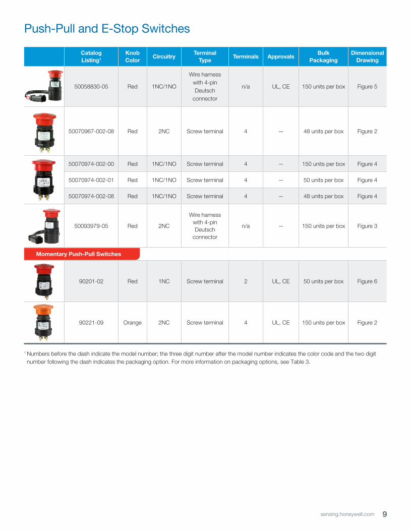
9sensing.honeywell.com
CatalogListing1
KnobColor
Circuitry Terminal
TypeTerminals Approvals
BulkPackaging
DimensionalDrawing
50058830-05 Red 1NC/1NO
Wire harnesswith 4-pin Deutsch
connector
n/a UL, CE 150 units per box Figure 5
50070967-002-08 Red 2NC Screw terminal 4 — 48 units per box Figure 2
50070974-002-00 Red 1NC/1NO Screw terminal 4 — 150 units per box Figure 4
50070974-002-01 Red 1NC/1NO Screw terminal 4 — 50 units per box Figure 4
50070974-002-08 Red 1NC/1NO Screw terminal 4 — 48 units per box Figure 4
50093979-05 Red 2NC
Wire harness with 4-pin Deutsch
connector
n/a — 150 units per box Figure 3
90201-02 Red 1NC Screw terminal 2 UL, CE 50 units per box Figure 6
90221-09 Orange 2NC Screw terminal 4 UL, CE 150 units per box Figure 2
Momentary Push-Pull Switches
Push-Pull and E-Stop Switches
1 Numbers before the dash indicate the model number; the three digit number after the model number indicates the color code and the two digit number following the dash indicates the packaging option. For more information on packaging options, see Table 3.

10 sensing.honeywell.com
Push-Pull and E-Stop Switches
Figure 2. Push-pull/E-stop switches with 2NC circuitry and screw terminal
Figure 3. Push-pull/E-stop switches with 2NC circuitry and Deutsch connector, 50093979
Figure 1. Push-pull/E-stop switches with 2NO circuitry and screw terminal
DIMENSIONAL DRAWINGS
85 mm[3.36 in]
38 mm[1.5 in]
200 mm[7.87 in]
Wiring diagram
Terminal view
RedConnector
Red
White
White
4
3
2
1
E-stop switchPull
A B
C D
PVC sleeve, black
18 AWG wiresper SAE J1128,type SXL
Deutsch connector DT04-4P mates with DT06-4S
Bottom view
Pull
A
Wiring diagram
B
C D
1
2
36
5
4
Listing1
mm [in]
2 mm [in] 3mm [in]
4mm [in]
5mm [in]
6mm [in]Total Pulled Pushed
87944Ø 45,21[Ø 1.78]
74,4 [2.93]
77,98 [3.07]
73,15[2.88]
29,72[1.17]
13,46[0.53]
Ø 38,63[Ø 1.521]
Ø 33,02Ø [1.30]
88843Ø 45,21[Ø 1.78]
74,4 [2.93]
—73,15[2.88]
32,26[1.27]
10,92[0.43]
Ø 38,63[Ø 1.521]
Ø 33,02Ø [1.30]
Listing1
mm [in]
2 mm [in] 3mm [in]
4mm [in]
5mm [in]
6mm [in]Total Pulled Pushed
87941Ø 45,21[Ø 1.78]
—77,98[3.07]
73,15[2.88]
29,72[1.17]
13,46[0.53]
Ø 38,63[Ø 1.521]
Ø 33,02[Ø 1.30]
89496Ø 45,21[Ø 1.78]
73,01[2.875]
—73,15[2.88]
32,26[1.27]
10,92[0.43]
Ø 38,63[Ø 1.521]
Ø 33,02[Ø 1.30]
90221Ø 45,21[Ø 1.78]
73,01[2.875]
—73,15[2.88]
32,13[1.265]
10,92[0.43]
Ø 38,63[Ø 1.521]
Ø 33,02[Ø 1.30]
50070967Ø 45,21[Ø 1.78]
73,01[2.875]
— —29,6
[1.165]—
Ø 38,63[Ø 1.521]
Ø 33,02[Ø 1.30]
Pull
A B
C D
Wiring diagramBottom view
1
23
6
5
4

11sensing.honeywell.com
Push-Pull and E-Stop Switches
Figure 5. Push-pull/E-stop switches with 1NC/1NO circuitry and Deutsch connector, 50058830
Figure 6. Push-pull/E-stop switches with 1NC circuitry and screw terminal, 90201
78,49 mm[3.09 in]
32,26 mm[1.27 in]
10,92 mm[0.43 in]
Ø 33,02 mm[Ø 1.3 in]
Wiring diagramNormal position: A-B is closedPushed position: A-B is open
Bottom view
Ø 38,63 mm[Ø 1.52 in]
Ø 45,21 mm[Ø 1.78 in]
A B
Pull
Figure 4. Push-pull/E-stop switches with 1NC/1NO circuitry and screw terminal
Wiring diagram
85 mm[3.36 in]
38 mm[1.5 in]
PVC sleeve, black 18 AWGgauge wire
Deutsch connector
DT04-4P mateswith DT06-4S
RedConnector
Red
White
White
4
3
2
1
171 mm ±19 mm[6.75 in ±0.75 in]
200 mm ±10 mm[7.876 in ±0.4 in]
E-stop switchPush
A B
C D
Ø 45,21 mm[Ø 1.78 in]
Terminal view
Listing1
mm [in]
2 mm [in] 3mm [in]
4mm [in]
5mm [in]
6mm [in]Total Pulled Pushed
87943Ø 45,21[Ø 1.78]
77,9 [3.07]
—73,15[2.88]
29,72[1.17]
13,46[0.53]
Ø 38,63[Ø 1.521]
Ø 33,02[Ø 1.30]
90098Ø 45,21[Ø 1.78]
73,15[2.88]
—73,15[2.88]
29,72[1.17]
13,46[0.53]
Ø 38,63[Ø 1.521]
Ø 33,02[Ø 1.30]
50070974Ø 45,21[Ø 1.78]
73,01 [2.875]
—73,01 [2.875]
29,6 [1.165]
—Ø 38,63[Ø 1.521]
Ø 33,02[Ø 1.30]
Pull
A
Bottom view Wiring diagram
B
C D
1
2
3
6
5
4

12 sensing.honeywell.com
Figure 7. Push-pull/E-stop switches with 1NC/1NO circuitry and screw terminal, 50087384
Push-Pull and E-Stop Switches
Mounting knobs
Figure 9. 50071756
Figure 8. 50071755
2 x 1,02 mm[2 x 0.04 in]
2 x 2,03 mm[2 x 0.08 in]
2 x 1,02 mm[2 x 0.04 in]
2 x R 5,33 mm[2 x R 0.21 in]
4 x 1,91 ±0,254 mm[4 x 0.075 ±0.01 in]
1,14 ±0,08 mm[0.045 ±0.003 in]
R 0,76 mm[R 0.03 in]
R 0,254 mm[R 0.01 in]
2 x 1,02 mm[2 x 0.04 in]
2 x 1,27 mm[2 x 0.05 in]
2 x 1,27 mm[2 x 0.05 in]
Ø 9,91 mm[Ø 0.39 in]
3,76 mm[0.148 in]
4,57 mm[0.18 in]
Ø 44,07 mm[Ø 1.735 in]
Ø 45,21 mm*[Ø 1.78 in]*
Ø 10,16 ±0,05 mm[Ø 0.4 in ±0.002 in]
Ø 5,08 mm[Ø 0.2 in]
12,1 mm[0.476 in]
2,03 mm typ.[0.08 in typ.]
R 0,38 mm[R 0.015 in]
R 1,6 mm[R 0.063 in]
R 0,51 mm[R 0.02 in]
R 2,54 mm[R 0.1 in]
7,5 mm[0.295 in]
0,51 mm[0.02 in]
8 x 1,02 mm[8 x 0.04 in]
4 x 45°
1,14 mm[0.045 in]
7,11 mm[0.28 in]
19,56 mm[0.77 in]
19,69 mm*[0.775 in]*
R 19,69 mm[R 0.775 in]
R 20,32 mm*R [0.8 in]*
Ø 33,53 mm[Ø 1.32 in]
Ø 34,04 ±0,05 mm*Ø [1.34 ±0.002 in]*
Ø 30,99 ±0,05 mm[Ø 1.22 in ±0.002 in]
*Dimensions are acceptable for life of mold
60 mm[2.36 in]
Ø 60 mm[Ø 2.36 in]
Ø 38,5 mm[Ø 1.52 in]
Pull
A
Bottom view Wiring diagram
B
C D

13sensing.honeywell.com
Figure 13. Mounting nut 84508
Figure 14. Mounting clip 87770
12,19 mm[0.48 in]
Ø 14,22 mm[Ø 0.56 in]
Ø 1,57 mm[Ø 0.062 in]
Ø 4,45 mm[Ø 0.175 in]
9,53 mm[0.375 in]
25,4 mm[1 in]
10,16 mm[0.4 in]
8,89 mm[0.35 in]
0,254 mm[0.01 in]
8 x 28°
16,38 mm[0.645 in]
12,7 mm[0.5 in]
35° typ.6 x Ø 5,08 mm
[6 x Ø 0.2 in]
R 0,76 mm[R 0.03 in]
7,62 mm[0.3 in]
2 x 0,76 mm x 45°[2 x 0.03 in x 45°]
Ø 28,83 mm[Ø 1.14 in]
Ø 26,42 mm[Ø 1.04 in]
Ø 30,48 mm[Ø 1.2 in]
8 x 2,03 mm[8 x 0.08 in]
8 x 1,52 mm[8 x 0.06 in]
Ø 17,53 mm[Ø 0.69 in]
Figure 11. Recommended mounting hole
Figure 12. Mounting screw 81908
Mounting plate thickness: 1,3 mm to 4,8 mm [0.05 in to 0.19 in]Part numbers: 87941, 87943, 88843, 89496, 90201, 90221,
90098, 50070967, and 50070974
R 1,65 mm[R 0.065 in]
11,43 mm[0.45 in]
Ø 22,1 mm[Ø 0.87 in]
Figure 10. Recommended mounting hole
Part numbers: 87944, 50058830, 50087384, 50093979
R 3,3 mm[R 0.13 in]
Ø 22,1 mm[Ø 0.87 in]
13,2 mm[0.52 in]
1,3 mm to 4,8 mm[0.05 in to 0.19 in]
Ø 6,86 mm / Ø 6,5 mm [Ø 0.27 in / Ø 0.256 in]
2,46 mm / 2,21 mm [0.097 in / 0.087 in]
Driver size 0,008 mm [0.0003 in] min.Zinc plate with black chromate
31,75 mm[1.25 in]
3,3 mm [0.13 in]low thread diameter
# 8-18 thread
4,32 mm [0.17 in]high thread diameter max.
Push-Pull and E-Stop Switches

WARRANTY/REMEDYHoneywell warrants goods of its manufacture as being free of defective materials and faulty workmanship. Honeywell’s standard product warranty applies unless agreed to otherwise by Honeywell in writing; please refer to your order acknowledgement or consult your local sales office for specific warranty details. If warranted goods are returned to Honeywell during the period of coverage, Honeywell will repair or replace, at its option, without charge those items it finds defective. The foregoing is buyer’s sole remedy and is in lieu of all other warranties, expressed or implied, including those of merchantability and fitness for a particular purpose. In no event shall Honeywell be liable for consequential, special, or indirect damages.
While we provide application assistance personally, through our literature and the Honeywell website, it is up to the customer to determine the suitability of the product in the application.
Specifications may change without notice. The information we supply is believed to be accurate and reliable as of this printing. However, we assume no responsibility for its use.
WARNINGPERSONAL INJURYDO NOT USE these products as safety or emergency stop devices or in any other application where failure of the product could result in personal injury. Failure to comply with these instructions could result in death or serious injury.
WARNINGMISUSE OF DOCUMENTATION• The information presented in this product sheet is for
reference only. Do not use this document as a product installation guide.
• Complete installation, operation, and maintenance information is provided in the instructions supplied with each product.
Failure to comply with these instructions could result in death or serious injury.
ADDITIONAL INFORMATION
The following associated literature is available on the Honeywell
website at sensing.honeywell.com:
• Product line guide
• Product range guide
• Product application-specific information
– Application note: Sensors and switches in front loaders
– Application note: Sensors and switches in mobile cranes
– Application note: Sensors and switches in oil rig applications
Push-Pull and E-Stop Switches
Find out moreHoneywell serves its customersthrough a worldwide networkof sales offices, representativesand distributors. For applicationassistance, current specifications,pricing or name of the nearestAuthorized Distributor, contactyour local sales office. To learn more about Honeywell’ssensing and switching products,call +1-815-235-6847 or1-800-537-6945, visitsensing.honeywell.com, or email inquiries [email protected]
Honeywell Sensing and Productivity Solutions9680 Old Bailes RoadFort Mill, SC 29707honeywell.com
006186-1-EN IL50 GLOApril 2016Copyright 2016 Honeywell International Inc. All rights reserved.


![Honeywell Pressure Switches · 2016-04-30 · Honeywell Pressure Switches High Pressure: HP Series, HE Series Factory set 150 psi to 4500 psi [10,34 bar to 310,26 bar] Low Pressure:](https://img.dokumen.tips/doc/110x75/5f842218cd8bc44621178411/honeywell-pressure-2016-04-30-honeywell-pressure-switches-high-pressure-hp-series.jpg)