Embed Size (px)
Citation preview
Operations, Service, and Parts Manual
L150, L250, L500 Tack Distributor
Manual No. 125201-02This manual applies
to machines beginning with Serial Number
1009317


Safety
Information and Specifications
Component Location
Operation
Maintenance
Schematics
Illustrated Parts List (IPL)
1
2
3
4
5
6
7
L150, L250, L500 Tack Distributor

L150, L250, L500 Tack Distributoriv
DISCLAIMER AND COPYRIGHT
Disclaimer:All information, illustrations and specifications in this manual are based on the latest information available at the time of publishing. The illustrations used in this manual are intended as representative reference views only. Moreover, because of our continuous product improvement policy, we may modify information, illustrations and/or specifications to explain and/or exemplify a product, service or maintenance improvement. We reserve the right to make any change at any time without notice. VT LeeBoy, Inc., VT LeeBoy, LeeBoy, and Rosco are all the same entity and are used interchangeably.
©2016 VT LeeBoy, Inc.LeeBoy reserves all copyright and other rights in this manual and the manual’s content. No part of this manual may be reproduced or used in any way without the written permission of LeeBoy, except as necessary to operate LeeBoy equipment.
California Proposition 65 WARNINGDiesel engine exhaust and some of its constituents are known to the State of California to cause cancer, birth defects, and other reproductive harm.
Battery posts, terminals and other related accessories contain lead and lead compounds, chemicals known to the State of California to cause cancer and other reproductive harm. Wash hands after handling.

TABLE OF CONTENTS
L150, L250, L500 Tack Distributor v
Page
Introduction . . . . . . . . . . . . . . . . . . . . . . . . . . . . . . . . .ix
Safety . . . . . . . . . . . . . . . . . . . . . . . . . . . . . . . . . . . . 1-1
Safety Precautions . . . . . . . . . . . . . . . . . . . . . . . . . . . . . 1-4
Safety Decal Locations . . . . . . . . . . . . . . . . . . . . . . . . . . 1-7
Safety Decals Care . . . . . . . . . . . . . . . . . . . . . . . . . . . . . 1-8
Specific Precautions . . . . . . . . . . . . . . . . . . . . . . . . . . . . 1-8
Information and Specifications . . . . . . . . . . . . . . . . . . . . . . . . 2-1
Limited Warranty Policy . . . . . . . . . . . . . . . . . . . . . . . . . . 2-2
Contact Information . . . . . . . . . . . . . . . . . . . . . . . . . . . . 2-3
Specifications . . . . . . . . . . . . . . . . . . . . . . . . . . . . . . . 2-4
L150T Specifications (Trailer) . . . . . . . . . . . . . . . . . . . . 2-5
L150S Specifications (Skid Mount) . . . . . . . . . . . . . . . . . . 2-6
L250T Specifications (Trailer) . . . . . . . . . . . . . . . . . . . . 2-7
L250S Specifications (Skid Mount) . . . . . . . . . . . . . . . . . . 2-8
L500T Specifications (Trailer) . . . . . . . . . . . . . . . . . . . . 2-9
L500S Specifications (Skid Mount) . . . . . . . . . . . . . . . . . . 2-10
Component Location . . . . . . . . . . . . . . . . . . . . . . . . . . . . . 3-1
Major Components . . . . . . . . . . . . . . . . . . . . . . . . . . . . . 3-3
Configurations . . . . . . . . . . . . . . . . . . . . . . . . . . . . . . . 3-4
Operation . . . . . . . . . . . . . . . . . . . . . . . . . . . . . . . . . . 4-1
General Information . . . . . . . . . . . . . . . . . . . . . . . . . . . . 4-3
Operational Safety . . . . . . . . . . . . . . . . . . . . . . . . . . 4-3
Receiving the Tack Distributor . . . . . . . . . . . . . . . . . . . . . . . 4-3
Pre-Start Inspection . . . . . . . . . . . . . . . . . . . . . . . . . . . . 4-3
Starting The Engine . . . . . . . . . . . . . . . . . . . . . . . . . . . . 4-4
Stopping the Engine . . . . . . . . . . . . . . . . . . . . . . . . . . . . 4-5
Material Considerations . . . . . . . . . . . . . . . . . . . . . . . . . . 4-5
Emulsified Asphalt . . . . . . . . . . . . . . . . . . . . . . . . . . 4-5

L150, L250, L500 Tack Distributor
vi
System Overview . . . . . . . . . . . . . . . . . . . . . . . . . . . . . . 4-6
Circulating System . . . . . . . . . . . . . . . . . . . . . . . . . . 4-6
Burner System . . . . . . . . . . . . . . . . . . . . . . . . . . . . 4-7
Tack Distributor Operation . . . . . . . . . . . . . . . . . . . . . . . . . 4-7
Loading the Tank . . . . . . . . . . . . . . . . . . . . . . . . . . 4-7
Preparing to Spray Tack . . . . . . . . . . . . . . . . . . . . . . . 4-8
Spray Wand . . . . . . . . . . . . . . . . . . . . . . . . . . . . . 4-10
Spray Bar (Option) . . . . . . . . . . . . . . . . . . . . . . . . . . . . . 4-11
Back Flush . . . . . . . . . . . . . . . . . . . . . . . . . . . . . . . . . 4-12
Optional Equipment . . . . . . . . . . . . . . . . . . . . . . . . . . . . 4-13
Overnight Emulsion Heater . . . . . . . . . . . . . . . . . . . . . . 4-13
In-Cab Controls . . . . . . . . . . . . . . . . . . . . . . . . . . . 4-13
Transporting the Distributor . . . . . . . . . . . . . . . . . . . . . . . . 4-14
Maintenance . . . . . . . . . . . . . . . . . . . . . . . . . . . . . . . . . 5-1
Maintenance Schedule . . . . . . . . . . . . . . . . . . . . . . . . . . . 5-3
Preparing Tack Distributor for Maintenance . . . . . . . . . . . . . 5-4
10-Hour or Daily Routine Maintenance . . . . . . . . . . . . . . . . 5-4
50-Hour (Initial) or Weekly Routine Maintenance . . . . . . . . . . . 5-4
100-Hour or Monthly Routine Maintenance . . . . . . . . . . . . . . 5-4
250-Hour or Quarterly Routine Maintenance . . . . . . . . . . . . . 5-4
500-Hour or Semi-Annual Routine Maintenance . . . . . . . . . . . 5-4
1000-Hour or Annual Routine Maintenance . . . . . . . . . . . . . . 5-4
Engine Maintenance . . . . . . . . . . . . . . . . . . . . . . . . . . . . 5-5
Check Engine Oil Level . . . . . . . . . . . . . . . . . . . . . . . 5-5
Change Engine Lubrication Oil . . . . . . . . . . . . . . . . . . . . 5-5
Change Engine Air Filter . . . . . . . . . . . . . . . . . . . . . . . 5-6
Burner System . . . . . . . . . . . . . . . . . . . . . . . . . . . . . . . 5-6
Trailer-Mounted Models . . . . . . . . . . . . . . . . . . . . . . . . . . 5-6
Changing Tires . . . . . . . . . . . . . . . . . . . . . . . . . . . 5-6
Brakes (L250 and L500 Models) . . . . . . . . . . . . . . . . . . . 5-7
Optional Components . . . . . . . . . . . . . . . . . . . . . . . . . . . 5-7
Battery . . . . . . . . . . . . . . . . . . . . . . . . . . . . . . . 5-7
Storage . . . . . . . . . . . . . . . . . . . . . . . . . . . . . . . . . . 5-8

L150, L250, L500 Tack Distributor
vii
Schematics . . . . . . . . . . . . . . . . . . . . . . . . . . . . . . . . . 6-1
Main Harness Assembly - L150/L250 Tack Tanks . . . . . . . . . . . . . . 6-3
Main Harness Assembly - L500 Tack Tank . . . . . . . . . . . . . . . . . 6-5
Illustrated Parts List . . . . . . . . . . . . . . . . . . . . . . . . . . . . . 7-1
Quick Reference . . . . . . . . . . . . . . . . . . . . . . . . . . . . . 7-3
L150 Trailer Assembly . . . . . . . . . . . . . . . . . . . . . . . . . . . 7-4
L150 Skid Assembly . . . . . . . . . . . . . . . . . . . . . . . . . . . . 7-6
L250 Trailer Assembly . . . . . . . . . . . . . . . . . . . . . . . . . . . 7-8
L250 Skid Assembly . . . . . . . . . . . . . . . . . . . . . . . . . . . . 7-10
L500 Trailer Assembly . . . . . . . . . . . . . . . . . . . . . . . . . . . 7-12
L500 Skid Assembly . . . . . . . . . . . . . . . . . . . . . . . . . . . . 7-14
L150 Hose Assemblies . . . . . . . . . . . . . . . . . . . . . . . . . . . 7-16
L250 / L500 Hose Assemblies . . . . . . . . . . . . . . . . . . . . . . . 7-18
Flush Tank System . . . . . . . . . . . . . . . . . . . . . . . . . . . . . 7-20
Propane Tank Assembly . . . . . . . . . . . . . . . . . . . . . . . . . . 7-22
Engine and Pump Assembly . . . . . . . . . . . . . . . . . . . . . . . . 7-24
Lower Liquid Asphalt Valve Assembly . . . . . . . . . . . . . . . . . . . . 7-26
Selector and Spray Valve Assemblies . . . . . . . . . . . . . . . . . . . 7-28
L150 Idler Axle Assembly . . . . . . . . . . . . . . . . . . . . . . . . . . 7-30
L250 / L500 Axle and Brake Assembly . . . . . . . . . . . . . . . . . . . 7-32
Spray Bar Assembly (Option) . . . . . . . . . . . . . . . . . . . . . . . . 7-34
Alphabetical Parts Index . . . . . . . . . . . . . . . . . . . . . . . . . . 7-36

L150, L250, L500 Tack Distributor
viii
NOTES

L150, L250, L500 Tack Distributor
ix
IntroductionThank you for purchasing the LeeBoy Model L150, L250 or L500 Tack Distributor. We wish you many years of safe and efficient operation.
READ THIS MANUAL PRIOR TO OPERATING the tack distributor. This manual is an important part of the tack distributor and should be kept with the unit at all times in the dedicated storage container. Though you may be familiar with similar equipment, you MUST read and understand this manual before operating this equipment to avoid injury and prevent any damage to the machine.
If this manual becomes lost or damaged, contact your authorized LeeBoy dealer immediately to order a replacement (see Contact Information in Section 2).
This manual is intended as a guide for the safe and efficient use of the tack distributor, along with procedures for proper operation and maintenance. This manual contains information that was available at the time of printing and is subject to change without notice.
Use this manual along with all other supplemental books and guides. Related service bulletins should be reviewed to provide information regarding some of the recent changes. Contact your local LeeBoy Dealer for the latest available information.
NOTE: This manual is accompanied by an engine instruction manual provided by the engine’s manufacturer. Please follow the operation and maintenance instructions in both manuals.

L150, L250, L500 Tack Distributor
x
NOTES

Page
Section 1 . . . . . . . . . . . . . . . . . . . . . . . . . . . . . . . . . . . 1-1
Safety Precautions . . . . . . . . . . . . . . . . . . . . . . . . . . . . . 1-4
Safety Decal Locations . . . . . . . . . . . . . . . . . . . . . . . . . . 1-7
Safety Decals Care . . . . . . . . . . . . . . . . . . . . . . . . . . . . . 1-8
Specific Precautions . . . . . . . . . . . . . . . . . . . . . . . . . . . . 1-8
L150, L250, L500 Tack Distributor 1-1
SAFETY
Section 1

NOTES
Safety
L150, L250, L500 Tack Distributor1-2

LOOK FOR THESE SYMBOLS THROUGHOUT THIS MANUAL. THESE ITEMS ARE EXTREMELY IMPORTANT FOR THE SAFETY OF YOU AND YOUR COWORKERS. READ AND UNDERSTAND THOROUGHLY. HEED THE WARNINGS AND FOLLOW THE INSTRUCTIONS.
Indicates a hazardous situation which, if not avoided, will result in death or serious injury.
Indicates a hazardous situation which, if not avoided, could result in death or serious injury.
Indicates a hazardous situation which, if not avoided, could result in minor or moderate injury.
Indicates a situation which can cause damage to the equipment, personal property and/or the environment, or cause the LeeBoy L150, L250, L500 Tack Distributor to operate improperly.
NOTE: Indicates a procedure, practice or condition that should be followed in order for the Tack Distributor or component to function in the manner intended.
This manual provides important information to familiarize you with safe operating and maintenance procedures for the LeeBoy L150, L250, and L500 Tack Distributors.
Safety is everyone’s business and our top concern. Knowing the guidelines covered in this section will help ensure safe and efficient operation of the equipment.
Keep safety decals on the machine in good condition. If safety decals are missing or damaged, replace them immediately. Safety decal replacement kits are available from your authorized LeeBoy dealer.
1
Safety
L150, L250, L500 Tack Distributor 1-3

Suffocation Hazard
Carbon monoxide poisoning is a serious condition that occurs as a result of improper ventilation.
• Never operate the engine on this distributor in an enclosed area with poor ventilation. Ensure proper ventillation to reduce risk of carbon monoxide poisoning or death.
Exhaust Hazard
All internal combustion engines create carbon monoxide gas during operation and special precautions are required to avoid carbon monoxide poisoning:
• Never block windows, vents or other means of ventilation.
The safety messages that follow have WARNING level hazards.
Crush Hazard
Keep bystanders away from work area before and during operation.
Modification Hazard
Never modify the LeeBoy distributor without the written consent of LeeBoy. Any modification can affect the safe operation of the tack distributor and may cause personal injury or death.
SAFETY PRECAUTIONS
The safety messages that follow have CAUTION level hazards.
Pre-Operation Hazard
Read and understand this Operation Manual before operating or servicing the engine to
ensure that safe operating practices and maintenance procedures are followed.
• Never permit anyone to service or operate the LeeBoy distributor without proper training.
• Safety signs and labels are additional reminders for safe operating and maintenance techniques.
• Contact LeeBoy or an authorized LeeBoy dealer for additional training.
• Make sure you are aware of all laws and regulations that are in effect for the location in which the tack distributor is operated.
• Make sure you have all necessary licenses to operate the tack distributor.
The safety messages that follow have DANGER level hazards.
Electrocution Hazard
If your distributor comes in contact with electric power lines, observe the following:
• Warn other workers to stay away and do not touch any control or any part of the distributor.
• If contact can be broken, drive the distributor away from the danger zone.
• Failure to observe these directions could result in electrocution or death.
Safety
L150, L250, L500 Tack Distributor1-4

Exposure Hazard
Operators of the tack distributor must be aware of their work environment and the equipment needed to work safely.
• Always wear personal protective equipment, including appropriate clothing, gloves, work shoes, and protection for eyes and ears, as required by the task at hand.
Fire and Explosion Hazard
Gas is flammable and explosive under certain conditions.
• Never use a shop rag to catch fuel.
• Wipe up all spills immediately.
• Never refuel with the engine running.
• Store any containers containing fuel in a well-ventilated area, away from any combustibles or sources of ignition.
Fire Hazard
When operating the distributor there is a risk for fire. Always keep safety equipment available.
• Keep a charged fire extinguisher within reach.
• Have all fire extinguishers checked periodically for proper operation and/or readiness.
• Always read and follow safety-related precautions found on containers of hazardous substances like parts cleaners, primers, sealants and sealant removers.
Entanglement/Sever Hazard
Verify there are no people, obstacles or other equipment near the distributor before starting the engine.
If the engine must be serviced while it is operating, remove all jewelry and tie back long hair before operating or servicing the distributor.
• Keep hands, other body parts, and clothing away from moving/rotating parts.
• Always stop the engine before beginning service.
• If you must run the engine during maintenance procedures, make sure you have a helper to keep bystanders clear of the tack distributor and make observations of moving parts as requested by the operator/repair person.
Alcohol and Drug Hazard
Never operate the distributor while under the influence of alcohol, drugs, or when ill.
Flying Object Hazard
Always wear eye protection when cleaning the LeeBoy L150, L250, L500 Tack Distributor with compressed air or high-pressure water.
Dust, flying debris, compressed air, pressurized water or steam may cause eye injury.
Burn Hazard
Some of the distributor’s surfaces become very hot during operation and shortly after shutdown.
• Keep hands and other body parts away from hot distributor surfaces.
• Handle hot components with heat-resistant gloves.
1
Safety
L150, L250, L500 Tack Distributor 1-5

The safety messages that follow have NOTICE level hazards.
Any part that is found defective as a result of inspection or any part whose measured value does not satisfy the standard or limit must be replaced.
Always tighten components to the specified torque. Loose parts can cause damage to the LeeBoy distributor or cause it to operate improperly.
Only use replacement parts approved by LeeBoy. Other replacement parts may affect warranty coverage.
Follow the guidelines of the EPA or other governmental agencies for the proper disposal of hazardous materials such as engine oil, fuel, and engine coolant. Consult the local authorities or reclamation facility.
Dispose of hazardous materials in accordance with all applicable laws and regulations. Never dispose of hazardous materials by dumping them into a sewer, on the ground, or into groundwater or waterways.
Clean all accumulated dirt and debris away from the body of the tack distributor and its components before you inspect the tack distributor or perform preventive maintenance procedures or repairs. Operating a tack distributor with accumulated dirt and debris will cause premature wear of tack distributor components. Accumulated dirt and debris also hinders effective tack distributor inspection.
Retrieve any tools or parts that may have dropped inside of the tack distributor to avoid improper tack distributor operation.
If any alert indicator illuminates during tack distributor operation, stop the engine immediately. Determine the cause and repair the problem before continuing to operate the tack distributor.
Safety
L150, L250, L500 Tack Distributor1-6

SAFETY DECAL LOCATIONS If a LeeBoy distributor has been repainted, it is extremely important that all decals referring to CAUTION, WARNING, and DANGER be replaced in their proper locations. A description of location is provided below for each safety label. For additional instructions, contact your dealer.
NOTE: It is the responsibility of the owner and operator to make sure that all safety labels are readable and located on the tack distributor as designated by LeeBoy.
FLAMMABLE!Fill tank before operating.DO NOT refill tank while burners are on or hot. Allow burners to cool before refilling.Failure to comply will result in death or serious injury.
856618
DANGER
PELIGRO
INFLAMMABLE !Faire le plein du réservoir avant d’utiliser la machine.NE PAS remplir le réservoir tant que les brûleurs sont allumés ou chauds.Laisser les brûleurs refroidir avant de remplir le réservoir.Le non-respect de cette règle entraînera des blessures graves, voire mortelles.
DANGER
¡INFLAMABLE!Llenar el tanque antes de usar la máquina.NO llenar el tanque si los quemadores están encendidos o calientes.Permitir que los quemadores se enfríen antes de llenar.Si no se cumple con esta disposición, se causará la muerte o lesiones graves.
EXPLOSION/FIRE HAZARD!Keep igniter away from tanks.
Failure to comply will result in death or serious injury.
856622
DANGER
¡RIESGO DE EXPLOSION/INCENDIO!Mantener el ignitor alejado de los tanques.Si no se cumple con esta disposición, se causará la muerte o lesiones graves.
PELIGRO
RISQUE D’EXPLOSION/INCENDIE !Maintenir l’allumeur à l’écart des réservoirs.Le non-respect de cette règle entraînera des blessures graves, voire mortelles.
DANGER
856624
BURN HAZARD!TIP OVER HAZARD!Ensure machine is level before operating.Use caution when unhitching unit from towing vehicle.Tip-over could result in spilling of TAC and equipment damage or personal injury.Failure to comply could result in death or serious injury.
WARNING¡RIESGO DE QUEMADURAS!¡RIESGO DE VUELCO!Comprobar que la máquina esté nivelada antes de usarla.Tener sumo cuidado al desenganchar la máquina del vehículo remolcador.Un vuelco puede causar derramamiento del TAC y daños al equipo o lesiones personales.Si no se cumple con esta disposición, se puede causar la muerte o lesiones graves.
RISQUE DE BRÛLURES !RISQUE DE BASCULEMENT !S’assurer que la machine est à niveau avant de la faire fonctionner.Faire preuve de prudence lors du dételage de la machine du véhicule de remorquage.Du TAC risque de se renverser et des dégâts matériels ou des blessures risquent de s'ensuivre en cas de basculement.Le non-respect de cette règle risque d’entraîner des blessures graves, voire mortelles.
ADVERTENCIA AVERTISSEMENT
8565
87
TAC PUMP FLUSHTurn flush valve on before starting engine.Failure to comply may result in pump damage.
OFF ON
CAUTION
ENJUAGUE DE BOMBA DE TACAbrir la válvula de enjuague antes de arrancar el motor.
Si no se cumple con esta disposición, se puede dañar la bomba.
APAG ENC
PRECAUCION
VIDANGE DE POMPE À TACActiver la vanne de vidange avant de faire démarrer le moteur.
Le non-respect de cette règle risque d’endommager la pompe.
ARRÊT MARCHE
ATTENTION
BURN HAZARD!Hot TAC could burn.Before removing spray wand nozzle ensure engine is off and wand valve is closed.Failure to comply could result in death or serious injury.
¡RIESGO DE QUEMADURAS!El TAC caliente puede causar quemaduras.Antes de quitar la boquilla de la varilla rociadora, asegurarse que el motor esté apagado y que la válvula de la varilla esté cerrada.Si no se cumple con esta disposición, se puede causar la muerte o lesiones graves.
856593
WARNING
ADVERTENCIA
RISQUE DE BRÛLURES !Le TAC chaud peut provoquer des brûlures.Avant de retirer la buse du tube de pulvérisation, s’assurer que le moteur est arrêté et que la vanne du tube est fermée.Le non-respect de cette règle risque d’entraîner des blessures graves, voire mortelles.
AVERTISSEMENT
TAC POURING VALVEUse caution when pouring TAC from valve.TAC is hot and will burn!Failure to comply could result in death or serious injury.
856617
WARNING
ADVERTENCIA
VANNE D’ÉCOULEMENT DE TACFaire preuve de prudence lorsque le TAC s’écoule de la vanne.Le TAC est très chaud et provoquera des brûlures !Le non-respect de cette règle risque d’entraîner des blessures graves, voire mortelles.
AVERTISSEMENT
VALVULA DE VACIADO DE TACTener sumo cuidado al vaciar TAC por la válvula.El TAC está caliente y causa quemaduras.Si no se cumple con esta disposición, se puede causar la muerte o lesiones graves.
856619
WARNING
BURNHAZARD!
HOT TACWILLBURN!
Stay backwhenTAC isbeingsprayed.
Failure tocomplycould result indeath orseriousinjury.
856592
DANGER DANGERFLAMMABLE
PELIGROINFLAMABLE INFLAMMABLE
FALL HAZARD!Use caution when stepping.
BURN HAZARD!Falling on or touching tank or heating element will cause burn.
Failure to comply could result in death or serious injury.
¡RIESGO DE CAIDAS!Pisar con sumo cuidado.¡RIESGO DE QUEMADURAS!Si se cae sobre el tanque o el elemento calentador o se tocan los mismos, se sufrirán quemaduras.Si no se cumple con esta disposición, se puede causar la muerte o lesiones graves.
8566
21
WARNING
ADVERTENCIA
RISQUE DE CHUTE !Se déplacer avec précaution.RISQUE DE BRÛLURES !Une chute sur le réservoir ou l’élément chauffant ou tout contact avec ceux-ci entraînera des brûlures.Le non-respect de cette règle risque d’entraîner des blessures graves, voire mortelles.
AVERTISSEMENT
8566
23
BURN HAZARD!Hot TAC will burn! Wear appropriate protective gear.Failure to comply could result in death or serious injury.
FILL TAC HERE - LLENAR CON TAC AQUI - REMPLIR DE TAC ICI
WARNING
ADVERTENCIA
RISQUE DE BRÛLURES !Le TAC chaud provoque des brûlures ! Porter un équipement de protection approprié.Le non-respect de cette règle risque d’entraîner des blessures graves, voire mortelles.
AVERTISSEMENT
¡RIESGO DE QUEMADURAS!¡El TAC caliente causa quemaduras! Usar equipo protector adecuado.Si no se cumple con esta disposición, se puede causar la muerte o lesiones graves.
Figure 1-1. Safety Decal Locations
1
Safety
L150, L250, L500 Tack Distributor 1-7

SPECIFIC PRECAUTIONS• Never perform any maintenance while burners are
ignited or the engine is running.
• Never light tack burners with anything but lighter provided.
• Never use fiber-based seal coat as this could damage the pump and clog the spray wand.
• Always maintain tack level at least three inches above burner flue.
• Never exceed towing speed set by city, state, and federal laws. Drive at a lower speed when towing, especially over slippery or uneven surfaces.
• Never allow excessive tack to build up on tack tank. The tack tank may be accidentally ignited.
• Never fill fuel tank or tack while engine is running or propane burners are lighted.
• Always place chock blocks on wheels when the tank distributor is left unattended.
• Always be careful when igniting burners. Make sure the lighter is kept away from the fuel tank and any flammable materials.
• Always maintain decals on distributor and replace if missing or badly worn.
• Keep all unauthorized personnel away from working tack distributor. Any authorized persons should wear protective clothing and glasses.
• Always use a vehicle of adequate size when towing a tack distributor. Quick stops may not be possible when towing with an undersized vehicle.
• Never leave tack tank distributor unattended wile heating.
• Never remove spray wand nozzle while engine is running.
SAFETY DECALS CARE• Keep safety decals and signs clean and legible at all
times. Replace decals and signs that are missing or become impossible to read.
• Become familiar with the content and the position of each safety decal.
• When replacing parts that display a safety decal, ensure that the new part is fitted with a decal.
• Obtain replacement safety decals or signs from your authorized LeeBoy dealer.
Decal Installation (Sticker Type)
1. Be sure the installation area is clean and dry. Use hot, soapy water to clean the surface.
2. Thoroughly dry the surface.
3. Measure and test fit before removing decal paper backing.
4. Remove the smallest split backing paper and align decal over the specified area, carefully pressing exposed portion into place.
5. Slowly remove remaining backing and carefully smooth into place.
6. Small air pockets can be pierced with a pin and smoothed using a piece of decal backing.
Decal Installation (Top Protected)
1. Clean surface with hot, soapy water where decal will be applied. Leave wet.
2. Remove protective back paper and soak decal in clean soapy water before applying to alleviate air bubbles.
3. Smooth decal into place with a squeegee and check for air bubbles.
4. Small air pockets can be pierced with a pin and smoothed using a piece of the decal backing.
5. Carefully remove top paper.
Safety
L150, L250, L500 Tack Distributor1-8

Starting and Stopping Precautions
• Check all around the tack distributor to make sure there are no people working on the distributor or in the path of the distributor before starting. DO NOT start until area is clear. Death or serious injury can occur to bystanders from being crushed under a moving distributor.
DO NOT operate the engine in an enclosed area without proper ventillation. Exhaust gasses are odorless and deadly.
Parking Precautions
• Park tack distributor on level ground whenever possible and block wheels when not in use. On grades, park tack distributor with wheels securely blocked.
Operating Precautions
• Always comply with local regulations regarding moving equipment on public roads and highways.
• Know and use the hand signals required for a particular job. Know who has the responsibility for signaling.
• Make sure that all lights and reflectors comply with state and local regulations. Ensure they are clean and in working order.
• DO NOT stand between the equipment and the truck while the truck is being coupled with the tack distributor. Death or serious injury can result from being crushed between the towing vehicle and distributor unit.
• Use caution on rough ground, slopes, and while turning.
• Be alert for hazards and obstructions on the work site.
• Be aware of and understand the job site traffic flow patterns.
• Obey flagmen, road signs, and signals.
• Watch for bystanders. Never allow anyone to reach into the distributor during use.
Storage Precautions
• Store tack distributor in an area away from human activity.
• DO NOT permit children to play on or around the stored distributor. Serious injury or death can occur from improper/unauthorized use of the distributor.
• Make sure the unit is stored on a surface that is firm, level, and free of debris.
• Store the distributor inside a building or cover securely with a weatherproof tarpaulin.
Maintenance Precautions
• DO NOT attempt repairs unless trained to do so. Refer to manuals and experienced repair personnel for help.
• Before working on the distributor, securely block the distributor and any components that may fall. Block any working components to prevent unexpected movement while repairs are being made.
• Always wear safety glasses and other required safety equipment when servicing or making repairs.
• Disconnect battery before working on the electrical system.
• Avoid mechanical adjustments while the tack distributor is in motion or while engine is operating. If lubrication or mechanical adjustment is necessary:
1. Shut off engine.
2. Place distributor in a safe position.
3. Securely block wheels.
4. Use extreme caution.
• Never make repairs on pressurized components such as fluid lines, the gas system, or mechanical items until the pressure has been relieved.
• When inflating tires, use a self-attaching inflation chuck with remote shut-off.
1
Safety
L150, L250, L500 Tack Distributor 1-9

Battery Precautions (Optional)
While the engine is running or the battery is charging, hydrogen gas is being produced and can be easily ignited. Keep the area around the battery well-ventilated and keep sparks, open flame, and any other form of ignition out of the area.
• Always disconnect the battery ground cable before working on the unit to avoid injury from spark or short circuit. Electrical shock and burns can occur.
• DO NOT start the engine by shorting the starter circuit or any other starting method not stated in this manual. Only use the starting procedure as described in this manual to start the engine.
• Never charge a frozen battery. Always warm the battery to room temperature before charging.
• Keep all sparks and flames away from batteries, as gas given off by electrolytes is explosive.
• Acid propelled by an explosion can cause blindness if it comes into contact with eyes. Always wear safety glasses when working near batteries.
• If you come into contact with battery electrolyte solution, wash off immediately.
• To avoid electrolyte loss, DO NOT tip batteries more than 45 degrees.
Safety
L150, L250, L500 Tack Distributor1-10

Page
Information and Specifications . . . . . . . . . . . . . . . . . . . . . . . . 2-1
Limited Warranty Policy . . . . . . . . . . . . . . . . . . . . . . . . . . 2-2
Contact Information . . . . . . . . . . . . . . . . . . . . . . . . . . . . 2-3
Specifications . . . . . . . . . . . . . . . . . . . . . . . . . . . . . . . 2-4
L150T Specifications (Trailer) . . . . . . . . . . . . . . . . . . . . 2-5
L150S Specifications (Skid Mount) . . . . . . . . . . . . . . . . . . 2-6
L250T Specifications (Trailer) . . . . . . . . . . . . . . . . . . . . 2-7
L250S Specifications (Skid Mount) . . . . . . . . . . . . . . . . . . 2-8
L500T Specifications (Trailer) . . . . . . . . . . . . . . . . . . . . 2-9
L500S Specifications (Skid Mount) . . . . . . . . . . . . . . . . . . 2-10
LeeBoy L150, L250, L500 Tack Distributor 2-1
INFORMATION AND SPECIFICATIONS
Section 2

LIMITED WARRANTY POLICY
WarrantySubject to the limitations, exclusions, and claims procedures set forth herein, VT LeeBoy, Inc. warrants [to the first retail purchaser] that this product will be free from substantial defects in materials and workmanship during the warranty period.
If a defect in material or workmanship is found, your authorized LeeBoy Dealer is to be notified during the warranty period. LeeBoy and its authorized Dealer will repair or replace any part or component of the unit or part that fails to conform to the warranty during the warranty period.
The warranty period will begin on the initial start-up, training and delivery of the unit by the Dealer to the customer, and will expire after twelve (12) months following the delivery of the product to the first retail purchaser. (See Dealer for additional warranty.)
Manufacturers’ Warranties: Engines are warranted by their manufacturers and may have warranty coverage that differs from that of LeeBoy. LeeBoy does not warrant any engine.
Replacement parts furnished by LeeBoy are covered for the remainder of the warranty period applicable to the unit or component in which such parts are installed.
LeeBoy has the right to repair any component or part before replacing it with a new one.
All new replacement parts purchased by a LeeBoy Dealer will carry a six-month warranty.
This Limited Warranty is governed by the laws of the State of North Carolina.
THE FOREGOING WARRANTY IS EXCLUSIVE AND IN LIEU OF ALL OTHER EXPRESSED, STATUTORY AND IMPLIED
WARRANTIES APPLICABLE TO UNITS, ENGINES, OR PARTS INCLUDING WITHOUT LIMITATION, ALL IMPLIED WARRANTIES
OF MERCHANTABILITY OR FITNESS FOR ANY PARTICULAR USE OR PURPOSE OR AGAINST INFRINGEMENT.
Items Not CoveredLeeBoy is not responsible for the following:
All used units or used parts of any kind.
Repairs due to normal wear and tear or brought about by abuse or lack of maintenance of the machine.
Attachments not manufactured or installed by LeeBoy.
Liability for incidental or consequential damages of any type including, but not limited to, lost profits or expenses of acquiring
replacement equipment.
LimitationsVT LeeBoy , Inc. has no obligation for:
Any defects caused by misuse, misapplication, negligence, accident, or failure to maintain or use in accordance with the most current operating instructions.
Unauthorized alterations.
Defects or failures caused by any replacement parts or attachments not manufactured by or approved by LeeBoy.
Failure to conduct normal maintenance and operating service including, without limitation, providing lubricants, coolant, fuel, tune-ups, inspections, or adjustments.
Unreasonable delay, as established by LeeBoy, in making the applicable units or parts available upon notification of a service notice ordered by same.
Warranty Responsibility: The warranty responsibility on all engines rests with the manufacturer of the engine.
Warranty and Parts Support: LeeBoy may have support agreements with some engine manufacturers for warranty and parts support. However, LeeBoy does not warrant the engine.
This Limited Warranty sets forth your sole remedy in connection with the sale or use of the LeeBoy product covered by this Limited Warranty.
This Limited Warranty extends only to the first retail purchaser, and is not transferable.
In the event any portion of this Limited Warranty shall be determined to be invalid under any applicable law, such provision shall be deemed null and void and the remainder of the Limited Warranty shall continue in full force and effect.
Other LimitationsIN NO EVENT, WHETHER AS A RESULT OF BREACH OF CONTRACT OR WARRANTY OR ALLEGED NEGLIGENCE OR LIABILITY WITHOUT FAULT, SHALL LEEBOY BE LIABLE FOR SPECIAL, INCIDENTAL OR CONSEQUENTIAL DAMAGES INCLUDING, WITHOUT LIMITATION, LOSS OF PROFIT OR REVENUE, COST OF CAPITAL, COST OF SUBSTITUTED EQUIPMENT, FACILITIES OR SERVICES, DOWNTIME COSTS, LABOR COSTS OR CLAIMS OF CUSTOMERS, PURCHASERS OR LESSEES FOR SUCH DAMAGES. IN NO EVENT WILL WARRANTY COMPENSATION, OR OTHER DAMAGES AVAILABLE FROM LEEBOY EXCEED THE PURCHASE PRICE OF THE PRODUCT.
LeeBoy L150, L250, L500 Tack Distributor2-2
Information and Specifications

NAMEPLATEThe nameplate contains the model and serial numbers used to identify the components for parts or service information.
Figure 2-1. Nameplate Location
CONTACT INFORMATIONFor information regarding parts and repairs for your machine, contact your Leeboy authorized dealer. If you need further assistance, contact LeeBoy directly.
Record dealer information in the space provided. For additional information about LeeBoy, please visit: www.leeboy.com.
RECORD OF OWNERSHIP:Please complete the following information for use if when you need to contact LeeBoy for service, parts or literature.
Sales Representative:
Dealership Name:
Dealership Address:
Dealership Phone:
Model Number:
Serial Number:
Date of Purchase:_____________________________________________
2
LeeBoy L150, L250, L500 Tack Distributor 2-3
Information and Specifications

SPECIFICATIONS LeeBoy Tack Distributors are designed to provide commercial pavers with an efficient and easily operated unit for tack coating on commercial job sites. The tack distributor is a dependable, low-maintenance addition to a contractor’s equipment fleet.
All units are equipped with 40 feet of hose, a six-foot spray wand and two propane burners. Trailer-mounted units are prewired for towing and include safety chains with a two-inch ball or pintle eye hitch (pintle eye is standard on the L500 model). The L250 model is equipped with single-axle electric brakes and emergency break-away switches. The L500 is equipped with electric brakes on both axles and emergency break-away switches.
The tack distributor is available in a skid-mount or trailer-mount version, with three tack tank sizes: 150, 250 or 500 gallons.
The trailer-mounted tack distributor can be towed behind a pick-up or larger vehicles for speed and productivity. All models are equipped with a ball hitch or pintle eye option and safety chains for ease of towing. (Figure 2-2)
Figure 2-2. Trailer Mount
Skid-mount units are built to install or load directly onto a flatbed. (Figure 2-3) It is important to secure the unit onto the vehicle. Options are also available for skid-mount models.
Figure 2-3. Skid Mount
Optional engine packages include an electric starter and battery for the standard Honda engine, or manual and electric starter and battery for Hatz engines. Other optional components include an emulsion heater for maintaining asphalt temperature during cold weather applications or preventing asphalt from setting up when stored overnight. An optional spray bar adds versatility to coating applications. Completing the option package is the in-truck control, which allows the operator to operate the spray bar from inside the towing vehicle.
The specifications provided in this section include weights, dimensions, performance, and torque values for both metric and standard inch fasteners.
LeeBoy L150, L250, L500 Tack Distributor2-4
Information and Specifications

L150T Specifications (Trailer)
7’ 2”(2.2 m)
11’ (3.4 m) 6’ 6” (2 m)
Table 2-1. LeeBoy Model L150T Tack Distributor (Trailer)
ITEM SPECIFICATION
Engine 4.8 HP (3.6 kW) Honda Gas Engine
Asphalt PumpCustom-Designed .761 CIR (cubic inches per revolution) / 7 GPM (gallons per minute)
Heat System Two (2) 54,000 BTU Propane Burners
Temperature Gauge 50° - 300° F (10° - 150° C)
Tank Dimensions
Length: 11 ft. (3.4 m)
Width: 6 ft. 6 in. (2 m)
Height: 7 ft. 2 in. (2.2 m)
Capacity 150 gal (568 L)
Hose and Reel 40 ft. (12.2 m) heavy-duty hose with reel.
Wand 6-ft. (1.8 m) Wand (with On/Off valve and removable spray tip).
Flush Tank 7 gal. (26.5 L)
Shipping Weight 1556 lbs. (706 kg)
Loaded Weight 2900 lbs. (1315 kg)
Optional Equipment
8-ft. Spray Bar: Folds to a lockable position. Separate cut-off valves to control each spray nozzle.
Electric Starter and Battery
In-Cab Controls
Overnight Heater
Pintle Eye
5 HP (3.7 kW) Hatz Diesel Engine
2
LeeBoy L150, L250, L500 Tack Distributor 2-5
Information and Specifications

L150S Specifications (Skid Mount)
6’ 4” (1.9 m)
6’ 6”(2 m)
4’ (1.2 m)
Table 2-2. LeeBoy Model L150S Tack Distributor (Skid Mount)
ITEM SPECIFICATION
Engine 4.8 HP (3.6 kW) Honda Gas Engine
Asphalt PumpCustom-Designed .761 CIR (cubic inches per revolution) / 7 GPM (gallons per minute)
Heat System Two (2) 54,000 BTU Propane Burners
Temperature Gauge 50° - 300° F (10° - 150° C)
Tank Dimensions
Length: 6 ft. 4 in. (1.9 m)
Width: 4 ft. (1.2 m)
Height: 6 ft. 6 in. (2 m)
Capacity 150 gal. (568 L)
Hose and Reel 40 ft. (12.2 m) heavy-duty hose with reel.
Wand 6-ft. (1.8 m) Wand (with On/Off valve and removable spray tip).
Flush Tank 7 gal. (26.5 L)
Shipping Weight 900 lbs. (408 kg)
Loaded Weight 2244 lbs. (1017 kg)
Optional Equipment
8-ft. Spray Bar: Folds to a lockable position. Separate cut-off valves to control each spray nozzle.
Electric Starter and Battery
In-Cab Controls
Overnight Heater
5 HP (3.7 kW) Hatz Diesel Engine
LeeBoy L150, L250, L500 Tack Distributor2-6
Information and Specifications

L250T Specifications (Trailer)
6’ 6” (2 m)11’ 6” (3.5 m)
7’ 6”(2.3 m)
Table 2-3. LeeBoy Model L250T Tack Distributor (Trailer)
ITEM SPECIFICATION
Engine 4.8 HP (3.6 kW) Honda Gas Engine
Asphalt PumpCustom-Designed .761 CIR (cubic inches per revolution) / 7 GPM (gallons per minute)
Heat System Two (2) 54,000 BTU Propane Burners
Temperature Gauge 50° - 300° F (10° - 150° C)
Tank Dimensions
Length: 11 ft. 6 in. (3.5 m)
Width: 6 ft. 6 in. (2 m)
Height: 7 ft. 6 in. (2.3 m)
Capacity 250 gal. (946 L)
Hose and Reel 40 ft. (12.2 m) heavy-duty hose with reel.
Wand 6-ft (1.8 m) Wand (with On/Off valve and removable spray tip).
Flush Tank 7 gal. (26.5 L)
Shipping Weight 2179 lbs. (988 kg)
Loaded Weight 4500 lbs. (2041 kg)
Optional Equipment
8-ft. Spray Bar: Folds to a lockable position. Separate cut-off valves to control each spray nozzle.
Electric Starter and Battery
In-Cab Controls
Overnight Heater
Pintle Eye
5 HP (3.7 kW) Hatz Diesel Engine
2
LeeBoy L150, L250, L500 Tack Distributor 2-7
Information and Specifications

L250S Specifications (Skid Mount)
7’ (2.1 m)
6’ 6” (2 m) 4’ 4” (1.3 m)
Table 2-4. LeeBoy Model L250S Tack Distributor (Skid Mount)
ITEM SPECIFICATION
Engine 4.8 HP (3.6 kW) Honda Gas Engine
Asphalt PumpCustom-Designed .761 CIR (cubic inches per revolution) / 7 GPM (gallons per minute)
Heat System Two (2) 54,000 BTU Propane Burners
Temperature Gauge 50° - 300° F (10° - 150° C)
Tank Dimensions
Length: 6 ft. 6 in. (2 m)
Width: 4 ft. 4 in. (1.3 m)
Height: 7 ft. (2.1 m)
Capacity 250 gal (946 L)
Hose and Reel 40 ft. (12.2 m) heavy-duty hose with reel.
Wand 6-ft. (1.8 m) Wand (with On/Off valve and removable spray tip).
Flush Tank 7 gal. (26.5 L)
Shipping Weight 1380 lbs. (626 kg)
Loaded Weight 3701 lbs. (1678 kg)
Optional Equipment
8-ft. Spray Bar: Folds to a lockable position. Separate cut-off valves to control each spray nozzle.
Electric Starter and Battery
In-Cab Controls
Overnight Heater
5 HP (3.7 kW) Hatz Diesel Engine
LeeBoy L150, L250, L500 Tack Distributor2-8
Information and Specifications

L500T Specifications (Trailer)
6’ 4”(1.9 m)
14’ 6” (4.4 m) 6’ 6” (2 m)
Table 2-5. LeeBoy Model L500 Tack Distributor (Trailer)
ITEM SPECIFICATION
Engine 4.8 HP (3.6 kW) Honda Gas Engine
Asphalt PumpCustom-Designed .761 CIR (cubic inches per revolution) / 7 GPM (gallons per minute)
Heat System Two (2) 54,000 BTU Propane Burners
Temperature Gauge 50° - 300° F (10° - 150° C)
Tank Dimensions
Length: 14 ft. 6 in. (4.4 m)
Width: 6 ft. 6 in. (2 m)
Height: 6 ft .4 in. (1.9 m)
Capacity 500 gal (1893 L)
Hose and Reel 40 ft. (12.2 m) heavy-duty hose with reel.
Wand 6-ft (1.8 m) Wand (with On/Off valve and removable spray tip).
Flush Tank 7 gal. (26.5 L)
Shipping Weight 3050 lbs. (1383 kg)
Loaded Weight 7800 lbs. (3538 kg)
Optional Equipment
8-ft. Spray Bar: Folds to a lockable position. Separate cut-off valves to control each spray nozzle.
Electric Starter and Battery
In-Cab Controls
Overnight Heater
2-Inch (51 mm) Ball Hitch
5 HP (3.7 kW) Hatz Diesel Engine
2
LeeBoy L150, L250, L500 Tack Distributor 2-9
Information and Specifications

L500S Specifications (Skid Mount)
4’ 6” (1.4 m)9’ 9” (3 m)
5’ 6” (1.7 m)
Table 2-6. LeeBoy Model L500S Tack Distributor (Skid Mount)
ITEM SPECIFICATION
Engine 4.8 HP (3.6 kW) Honda Gas Engine
Asphalt PumpCustom-Designed .761 CIR (cubic inches per revolution) / 7 GPM (gallons per minute)
Heat System Two (2) 54,000 BTU Propane Burners
Temperature Gauge 50° - 300° F (10° - 150° C)
Tank Dimensions
Length: 9 ft 9 in (3 m)
Width: 4 ft 6 in (1.4 m)
Height: 5 ft 6 in (1.7 m)
Capacity 500 gal (1893 L)
Hose and Reel 40 ft. (12.2 m) heavy-duty hose with reel
Wand 6-ft (1.8 m) Wand (with On/Off valveand removable spray tip)
Flush Tank 7 gal (26.5 L)
Shipping Weight 2300 lbs (1043 kg)
Loaded Weight 7050 lbs (3197 kg)
Optional Equipment
8-ft. Spray Bar: Folds to a lockable position. Separate cut-off valves to control each spray nozzle.
Electric Starter and Battery
In-Cab Controls
Overnight Heater
5 HP (3.7 kW) Hatz Diesel Engine
LeeBoy L150, L250, L500 Tack Distributor2-10
Information and Specifications
Page
Component Location . . . . . . . . . . . . . . . . . . . . . . . . . . . . . 3-1
Major Components . . . . . . . . . . . . . . . . . . . . . . . . . . . . . 3-3
Configurations . . . . . . . . . . . . . . . . . . . . . . . . . . . . . . . 3-5
LeeBoy L150, L250, L500 Tack Distributor 3-1
COMPONENT LOCATION
Section 3

NOTES
Component Location
LeeBoy L150, L250, L500 Tack Distributor3-2

MAJOR COMPONENTS
1
2
3 4
5
6
7
8
9
1011
Figure 3-1. Location of Major Components
ITEM NO. CONTROL NAME FUNCTION
1 Hose ReelHolds the hose for the spray wand. Hose is 40 feet and can be easily extend-ed and retracted. Spray wand sits in a mount on the other side of the unit.
2Splash Plate and Asphalt Filler Neck
Remove splash plate on top of filler neck to fill the unit with asphalt. Be sure the splash plate is returned to its position before operating.
3 Flush Tank Contains the fluid used to flush and clean out the pump and system.
4 Propane TankThe propane tank provides gas to the burner system. The tank pressure should range from eight (8) to ten (10) pounds of pressure.
5Liquid Propane (LP)Pressure Gauge
Pressure gauge displaying LP tank pressure.
6 Fuel Tank Holds fuel for engine.
7 Engine Gas engine is standard. Optional diesel engine.
8 Swivel JackUsed to hook and unhook the unit from the towing vehicle (trailer-mounted models only). Be sure to secure tires so unit will not roll.
9Emergency Break-Away System
Applies brakes in the event the tack distributor separates from the tow vehicle. Standard on the L250 and L500 models. (Trailer-mounted models only.)
10 Safety ChainsAttaches to the tow vehicle for additional safety while towing. (Trailer-mounted models only.)
11 Burner Used to heat the tack tank material.
3
Component Location
LeeBoy L150, L250, L500 Tack Distributor 3-3

CONFIGURATIONS
CONFIGURATION L150S L150T L250S L250T L500S L500T
4.8 HP (3.6 KW) Honda Engine X X X X X X
6-Foot (1.8 m) Spray Wand X X X X X X
40-Foot (12.2 m) Hose Reel X X X X X X
Two (2) 54,000 BTU Propane Burners X X X X X X
2-Inch (51 mm) Ball Hitch X X Optional
Safety Chains X X X
Pintle Eye Optional Optional X
Pre-Wired for Towing X X X
Single-Axle Electric Brakes X
Dual Axle Electric Brakes X
Emergency Breakaway Switches X X
150-Gallon (468 L) Tank X X
250-Gallon (946 L) Tank X X
500-Gallon (1,893 L) Tank X X
8-Foot (2.4 m) Spraybar Optional Optional Optional Optional Optional Optional
In-Cab Controls Optional Optional Optional Optional Optional Optional
Overnight Heater Optional Optional Optional Optional Optional Optional
Electric Start Optional Optional Optional Optional Optional Optional
5 HP (3.7 kW) Hatz Diesel Engine Optional Optional Optional Optional Optional Optional
Component Location
LeeBoy L150, L250, L500 Tack Distributor3-4

Page
Operation . . . . . . . . . . . . . . . . . . . . . . . . . . . . . . . . . . 4-1
General Information . . . . . . . . . . . . . . . . . . . . . . . . . . . . 4-3
Operational Safety . . . . . . . . . . . . . . . . . . . . . . . . . . 4-3
Receiving the Tack Distributor . . . . . . . . . . . . . . . . . . . . . . . 4-3
Pre-Start Inspection . . . . . . . . . . . . . . . . . . . . . . . . . . . . 4-3
Starting The Engine . . . . . . . . . . . . . . . . . . . . . . . . . . . . 4-4
Stopping the Engine . . . . . . . . . . . . . . . . . . . . . . . . . . . . 4-5
Material Considerations . . . . . . . . . . . . . . . . . . . . . . . . . . 4-5
Emulsified Asphalt . . . . . . . . . . . . . . . . . . . . . . . . . . 4-5
System Overview . . . . . . . . . . . . . . . . . . . . . . . . . . . . . . 4-6
Circulating System . . . . . . . . . . . . . . . . . . . . . . . . . . 4-6
Burner System . . . . . . . . . . . . . . . . . . . . . . . . . . . . 4-7
Tack Distributor Operation . . . . . . . . . . . . . . . . . . . . . . . . . 4-7
Loading the Tank . . . . . . . . . . . . . . . . . . . . . . . . . . 4-7
Preparing to Spray Tack . . . . . . . . . . . . . . . . . . . . . . . 4-8
Spray Wand . . . . . . . . . . . . . . . . . . . . . . . . . . . . . 4-10
Spray Bar (Option) . . . . . . . . . . . . . . . . . . . . . . . . . . 4-11
Back Flush . . . . . . . . . . . . . . . . . . . . . . . . . . . . . . 4-12
Optional Equipment . . . . . . . . . . . . . . . . . . . . . . . . . . . . 4-13
Overnight Emulsion Heater . . . . . . . . . . . . . . . . . . . . . . 4-13
In-Cab Controls . . . . . . . . . . . . . . . . . . . . . . . . . . . 4-13
Transporting the Distributor . . . . . . . . . . . . . . . . . . . . . . . . 4-14
LeeBoy L150, L250, L500 Tack Distributor 4-1
OPERATION
Section 4

NOTES
Operation
LeeBoy L150, L250, L500 Tack Distributor4-2

GENERAL INFORMATIONBefore operating the LeeBoy Model L150, L250 or L500 Tack Distributor, become familiar with the operational procedures outlined in this section. Also review Safety in Section 1.
Operation Hazard! Only authorized personnel who are properly trained in the operation of the tack distributor should operate the LeeBoy Model L150, L250, and L500 Tack Distributors.
Operation Hazard! DO NOT operate a distributor unit that needs repair or scheduled maintenance. Make any repairs promptly and perform routine maintenance at regular intervals (Section 5). Even minor damage can result in major system failure.
Operational Safety• Work slowly in tight areas.
• Avoid steep hills if possible.
• Use proper flags, barriers and warning devices, especially when parking in areas of traffic.
• DO NOT operate engine in a closed building.
• Never open a valve to the burner unless a flame is present. Make sure all valves are closed before propane is turned ON.
• Avoid leaving engine running without an operator present.
• Never fill the fuel tank when the engine is running.
• Always replace damaged or lost decals.
If equipped with battery, be sure the correct battery polarity is observed [negative (-) to negative (-) and positive (+) to positive (+)], when connecting a battery charger or jumper cable.
• Disconnect battery cables when working on the electrical system or welding on the unit.
• If battery needs a charge, be sure battery charger is off when making connections.
RECEIVING THE TACK DISTRIBUTORThe Tack Distributor was thoroughly inspected before shipment from the factory. Should any damage occur during transport, notify the shipping agent and your LeeBoy dealer immediately.
Inspect the machine upon arrival as outlined below:
1. Check engine oil level.
2. Inspect all hoses.
3. Check all spraying components.
4. Check for any missing parts or components.
5. Inspect the unit to ensure there were no dents or damage during transit.
PRE-START INSPECTIONThe tack distributor uses a Honda four-stroke, overhead-valve, single-cylinder engine coupled to a Viking spur gear pump. The system consists of an asphalt pump, a spray wand, hoses and valves for asphalt delivery. An optional eight-foot spray bar is also available.
A Viking spur gear pump supplies pressure to spray the asphalt throught the spray wand and optional spray bar. A relief valve adjusts the pressure. The spray wand allows the operator to spray asphalt in small areas or along pavement edges. The optional spray bar features a separate cut-off valve to control each of the six spray nozzles.
The tack distributor is available in three tank capacities: 150, 250 or 500 gallons. Two exhaust stacks at the rear of the unit direct burner exhaust up and away from the operating area. A discharge valve at the rear of the tank facilitates draining tank contents.
Always inspect the tack distributor unit before use for optimal performance. Repair or replace any malfunctioning, broken or missing parts promptly.
Pre-start inspection includes:
1. Check engine oil level.
2. Check fuel level.
3. Check all electrical functions before distributing asphalt.
4. Ensure operator’s area is free of debris.
4
Operation
LeeBoy L150, L250, L500 Tack Distributor 4-3

5. Ensure that all safety labels are in place and legible. These are as important as any other equipment on the unit, and should be replaced immediately if worn or damaged.
6. Ensure all covers and guards are in place.
7. Inspect components and ensure unit is clean.
8. Check tack level. Fill if needed.
9. Check propane gas level.
10. Check flow valves to ensure free flow.
11. Check flush tank level.
12. Check for cracked, broken or worn parts.
13. Check wheel lugs.
14. Check tire pressure.
STARTING THE ENGINEBefore operating the tack distributor, make sure the unit is secured so it does not roll or move during operation. Check the following components before starting the engine:
• Check the fuel level. Be sure to fill the fuel tank daily to avoid condensation.
• Check fuel lines and tank for any leaks.
• Check the engine oil level.
Failure to maintain the correct engine oil level is the greatest cause of engine failure.
• Check propane level.
• Check flush tank level.
• Check tack level and fill if needed. Tack level must be at least three inches above the burner flues.
NEVER start the engine unless there is tack material or flush material circulating in the system. Running a dry pump will cause pump failure and void the warranty.
To start the engine:
1. Turn flush valve ON before starting engine. (Figure 4-1)
FlushValve
Figure 4-1. Flush Valve
2. Move the fuel valve to the ON position. (Figure 4-2)
3. To start a cold engine, move the choke lever to the CLOSED position. (To restart a warm engine, leave the choke lever in the OPEN position).
4. Move the throttle lever away from the MIN position about 1/3 toward the MAX position.
5. Turn the engine switch to the ON position.
6. Grasp the recoil starter grip until you feel resistance, then pull briskly, cranking the engine. Return the starter grip gently back to its place. (If equipped with optional electric starter, turn the key to the START position and hold it there until the engine starts.)
Operation
LeeBoy L150, L250, L500 Tack Distributor4-4

MATERIAL CONSIDERATIONSThe liquid asphalt most commonly used in the LeeBoy tack distributor is emulsified asphalt. The information in this section is based upon industry standards. It is important to note that some asphalt product manufacturers may vary from industry standards, tailoring their products to local geographic conditions. and may provide superior performance to the standard grades.
Two asphalt products should NEVER be used in the tack distributor:
• Cutback Asphalt: These are asphalt products made by blending asphalt cement with gasoline, kerosene or other liquids that are highly flammable and can cause serious injury.
• Asphalt Cements: This is basic asphalt refined from petroleium used for hot mixes and surface treatments. These products must be heated higher than 200° F (93.3° C), which is higher than the heat capacity for these units. Asphalt cements will plug hoses or piping and are extremely difficult to remove.
Emulsified AsphaltEmulsified asphalt is produced by combining asphalt cements with water and an emulsifier. Emulsions are used because they reduce asphalt viscosity for lower temperature uses. Application temperatures range from 120° - 160° F (48.9° - 71.1° C)
The primary use for emulsified asphalts are surface treatments, fog seal, prime coat, cold-mix patching, road mix and tack coats.
There are many types and grades of asphalt products.Selecting liquid asphalt generally depends upon:
• Availability of various types of aggregate.
• Availability of various liquid asphalt grades.
• Climate conditions anticipated during application.
• Traffic conditions during application.
DO NOT mix emulsion types. Some combinations can be extremely incompatible and even hazardous. Mixing materials can increase the risk of fire or explosion.
1
2
3 4
Figure 4-2. Engine Controls
1 - Throttle
2 - Choke
3 - Fuel Valve
4 - Recoil Starter
DO NOT allow the starter grip to snap back against the engine. Return it gently to prevent damage to the starter.
Using the electric starter for more than five seconds at a time will overheat the starter motor and can damge it in time.
Using starting additives such as ether is not recommended.
7. If the choke lever was moved to the CLOSED position to start the engine, gradually move it to the OPEN position as the engine warms up.
8. Position the throttle lever for the desired engine speed.
STOPPING THE ENGINETo stop the engine in an emergency, simply turn the engine switch to the OFF position.
Under normal conditions, use the following procedures:
1. Move throttle lever to the MIN position.
2. Turn the engine switch to the OFF position.
3. Move the fuel valve lever to the OFF position.
4
Operation
LeeBoy L150, L250, L500 Tack Distributor 4-5

Emulsions are typically a thick, brown liquid when intially applied. When the asphalt cements starts to adhere to the surrounding material, the color changes to black. As water evaporates, the emulsion behaves more like pure asphalt cement.
Asphalt emulsions for surface treatments and seal coats are either anionic or cationic, which refers to the electrical charges surrounding the asphalt particles. Cationic emulsions have a positive electrical charge while anionic emulsions have a negative electrical charge. Cationic emulsions set more quickly in high humidity or cooler weather, while anionic emulsions work well in low humidity or warm weather conditions.
Application temperatures range from 120° - 160° F (48.9° - 71.1° C)
Store emulsified asphalts at 50° - 185° F (10° - 85° C), depending upon the grade of emulsion and its intended use.
DO NOT heat emulsified asphalt above 185° F (85° C). Elevated temperatures evaporate the water, increasing viscosity, and will produce an asphalt layer in the tank that will be very difficult to remove.
DO NOT allow emulsified asphalt to freeze, w hich breaks down the emulsion and separates the asphalt from water. This will result in two layers in the tank that will be very difficult to remove.
For more information about selecting, storing and handling liquid asphalt, obtain the “MS-19 Basic Asphalt Emulsion Manual” from the Asphalt Institute at www.asphaltinstitute.org.
Wear protective gloves and other protective gear for face, feet and body when working with hot material. If hot asphalt touches skin, flush area immediately with cold water. DO NOT apply ice directly to the affected area. Get medical attention promptly.
SYSTEM OVERVIEWThe circulating system and the burner system are the two primary operating systems for the tack distributors. Units are equipped with two propane burners, a propane tank, a hose reel with 40 feet of hose, and a spray wand. Trailer-mounted units include safety chains and a two-inch ball or pintle eye hitch, and are pre-wired for towing.
DO NOT operate the unit with leaking or damaged parts.
DO NOT smoke around the machine. Fuel, asphalt material and the fumes from each can explode when exposed to flame or heat.
Circulating SystemThe circulating system has an engine-driven pump to circulate material through the spray wand (and spray bar if equipped). The tack distributor delivers a volume of asphalt that is regulated variables, including the temperature of the asphalt, nozzle size and PSI setting at the relief valve.
The tack distributor is equipped with 1/4-inch nozzles (wand and spray bar) that deliver a 95-degree angle of spray. It is important that the operator applies constant and uniform pressure for uniform output. (Figure 4-3)
Spray Wand
Spray Bar
Figure 4-3. Spray Wand/Optional Spray Bar
Operation
LeeBoy L150, L250, L500 Tack Distributor4-6

Burner SystemThe burner system produces heat that is dissipated through the asphalt. (Figure 4-4) Because asphalt resists heat conducution, the amount of time necessary to heat the asphalt to a sufficient temperature for spraying will vary depending upon the type of material, tank size, amount of material in the tank and the weather temperature. Be sure to contact your asphalt supplier for more information about their asphalt product.
If it is necessary to heat asphalt that has cooled more than 20° - 30° F (-6.6° to -1.1° C) below the manufacturer’s recommended spraying temperature, use extreme care when reheating the material. If the asphalt is heated too hot or too quickly, hot spots will be created near the flue tubes along the bottom of the tank that could damage them or cause the material to break down.
The propane tank valve controls gas flow from the tank. The burner valve controls gas flow to the burner.
NEVER operate the burners if the flue tubes at the bottom of the tank are not covered with at least three inches (7.6 cm) of material as they can become too hot and ignite vapors.
NEVER operate the burners or the tack distributor in a confined area. Vapor build-up can ignite.
NEVER use a match or other source of flame to light the ignitor for the burner as an explosion could occur.
DO NOT smoke near the unit. Fuel, asphalt material and the associated fumes are extremely flammable.
Figure 4-4. Burner System
TACK DISTRIBUTOR OPERATIONThe LeeBoy tack distributors are designed to provide commercial pavers with an efficient means of tack coating on commercial job sites.
Only personnel who are trained to use the tack distributor should operate the unit.
Loading the TankIt is VERY important when loading material into the tack distributor that the new material is compatible with any residual material left in the tank. Incompatible materials can cause a chemical reaction that results in poor or wrong specifications for the job, but more importantly, increases the risk of fire or possible explosion. Therefore, it is imperative to clean the tank after each use. Also ensure there is no water or condensation inside before loading the tank. Hot material can turn water into steam that could be hot enough to burn.
Fumes from asphalt materials are poisonous and should not be inhaled. Always wear protective gear and DO NOT lean over the tank when filling to avoid hot gases, fumes or the possibility of hot asphalt contact.
Before loading the tank and operating the unit, always conduct a pre-start inspection and ensure the tank is clean. (Pages 4-3 and 4-4).
If your LeeBoy tack distributor is skid-mounted, be sure it is secured to the transporting vehicle. If you have a trailer-mounted distributor, ensure the ball or pintle latch is securely fastened to the towing vehicle. Always block the tires with a chock to prevent the unit from moving during operation.
If working at night or other low visibility conditions, equip the unit with special lighting. Use reflective tape on all sides of the unit and use impact barriers to protect workers from traffic hazards. Be sure all personnel wear reflective vests when working in these conditions.
4
Operation
LeeBoy L150, L250, L500 Tack Distributor 4-7

The asphalt temperature must reach the manufacturer’s recommended temperature before starting the engine. Trying to spray asphalt before it is warm enough will damage the pump.
To fill the tank:
SplashPlate
Figure 4-5. Splash Plate
1. Park the unit (or vehicle if skid-mounted) on a level surface.
2. Close or turn off ALL valves on the unit.
3. Remove the splash plate.
DO NOT put your hand inside the tank.
4. Fill the tank 90 percent full. DO NOT OVERFILL.
5. Replace the splash plate.
Preparing to Spray TackThe tack coat should be applied uniformly across the entire pavement surface. Application rate depends upon pavement condition. Too little tack coat can result in inadequate bonding between layers. Too much tack coat can create a lubricated slippage plane between layers. Rough surfaces require more tack coat than smooth surfaces.
Adjusting and setting components correctly is critical to achieving uniform tack coat. The nozzle patterns and distribution pressure work together to produce a uniform tack coat. There must be enough pressure
for the material to pass through the spray nozzle(s) at a constant rate, and spray patterns should be uniform. Differing coverages will result in streaks and gaps.
Emulsified tack coat materials may be applied to cool or even damp pavement, although such conditions require more time for the material to set.
If using on existing and milled pavements, clean or sweep the surface before applying any tack coat to prevent it from bonding to dirt and dust.
DO NOT operate the burners while the splash plate is open. Fire or an explosion can occur.
DO NOT operate the burners if the flue tubes in bottom of the tack tank are not covered with at least three inches (7.6 mm) of material. The hot tubes can ignite vapors and cause an explosion.
1. Make sure all valves are closed or in the OFF position.
2. Check asphalt level in tank. It must be at least three inches above flue before lighting burners.
3. Open the propane tank valve by turning it counterclockwise. (Figure 4-6)
Valve
Figure 4-6. Propane Tank Valve
4. Remove the ignitor wand from its stowed position.
5. Open valve on ignitor wand by turning it counterclockwise. (Figure 4-7)
6. Light ignitor using a torch striker.
Operation
LeeBoy L150, L250, L500 Tack Distributor4-8

NEVER use a match or other source of flame to light the ignitor for the burner as an explosion could occur.
1 2 3
Figure 4-7. Burner Ignitor
1 - Ignitor Wand Valve
2 - Burner Valve
3 - Burner Ignition
7. Regulate the propane pressure to 8 - 10 psi. (maximum) by adjusting knob on the regulator. (Figure 4-8)
1
2
Figure 4-8. Propane Pressure
1 - Propane Pressure Gauge
2 - Regulator Adjusting Knob
8. To light burner, hold the lit ignitor wand in front of the burner.
9. Turn the burner valve counterclockwise to open the gas flow (it should ignite within two seconds), then close after burner is lit by turning it clockwise. (Figure 4-7) If it doesn’t light immediately:
• Shut off the gas flow by turning the burner valve clockwise.
• Wait 30 seconds to allow pockets of trapped gas to purge.
• Repeat this procedure until burner is lit.
10. Repeat Steps 8 and 9 on burner on the other side of the unit.
11. After the burners are lit, close the wand ignitor valve by turning it clockwise and return ignitor wand to its storage bracket.
12. Check the temperature gauge behind engine to ensure the liquid asphalt is the right temperature according to material specifications . This should never exceed 180° F (82° C). Monitor the temperature several times while working. (Figure 4-9)
Figure 4-9. Temperature Gauge
13. Turn the liquid asphalt valve to the ON position. (Figure 4-10)
4
Operation
LeeBoy L150, L250, L500 Tack Distributor 4-9

1 2
Figure 4-10. Liquid Asphalt Valve
1 - Liquid Asphalt Valve
2 - Flush Valve
14. After asphalt has reached the appropriate temperature, start engine. (Page 4-4)
Never start the engine unless there is enough tack material circulating in the system.
DO NOT heat emulsified asphalt more than 185° F (29.9° C). Elevated temperatures evaporate the water and will produce an asphalt layer inside the tank that will be difficult to remove.
DO NOT allow emulsified asphalt to freeze. Freezing breaks the emulsion, separating asphalt from water. This will result in two layers in the tank that will be very difficult to remove.
Spraying the Tack CoatThe spray wand allows the operator to spray material in small areas and along pavement edges. A selector valve allows the tack material to flow to the spray wand or the optional spray bar described on Page 4-11.
Figure 4-11. Spraying Tack
Spray Wand1. Unwind hose from the reel and remove the spray
wand from its storage bracket.
Figure 4-12. Hose Reel
Operation
LeeBoy L150, L250, L500 Tack Distributor4-10

2. Open the spray wand valve on the nozzle.
3. Set the desired pressure. (The least amount of pressure on relief, the longer the life of the pump).
4. Spraying Tack:
• Liquid asphalt valve should be ON. (Figure 4-10)
• Circulating valve should be CLOSED. (Figure 4-13)
• Selector valve should be ON. (Figure 4-13)
• Flush valve should be CLOSED. (Figure 4-10)
• Turn the spray wand valve ON when ready to spray spray tack. (Figure 4-13)
NOTE: When allowing machine to run for short periods of time without spraying, open the circulating valve to relieve excessive pump pressure.
1
2
3
4
Figure 4-13. Spray Valves
1 - Spray Bar Valve (Option)
2 - Spray Wand Valve
3 - CirculatingValve
4 - Selector Valve
SPRAY BAR (OPTION)The optional spray bars provides the operator the means to distribute tack material over a larger area, i.e., a road or driveway surface. Mounted on the rear of the unit, the spray bar is equipped with separate cut-off valves for each spray nozzles or all nozzles needed.
Figure 4-14. Optional Spray Bar
The two spray bars fold down to extend the spraying width beyond each side of the unit, then fold back up after use. The spray bar height can be adjusted
To operate the spray bar:
1. After determining width of the spray pattern needed, open each individual spray bar nozzle valves according to the width of the area you’re coverying. (Figure 4-15)
NozzleSprayValve
Figure 4-15. Nozzle Spray Valve
4
Operation
LeeBoy L150, L250, L500 Tack Distributor 4-11

Open the spray bar nozzle valves before opening the spray bar select valve to prevent the line from becoming pressurized and possibly spraying hot tack on the operator or bystanders.
2. Open the spray bar valve. (Figure 4-13)
3. Close the spray wand valve. (Figure 4-13)
4. Follow the procedures on Pages 4-8 through 4-10 for operating and spraying tack.
5. After operation, back flush following procedures on Page 4-12.
When moving from one job site to another, turn the individual nozzle valves off to prevent dripping.
NOTE: Height of the spray bar may be adjusted by removing two bolts and raising or lowering the bar to desired height.
BACK FLUSHCleaning the circulating system daily prevents asphalt material from clogging components. Some residue can be left on the inner surfaces that will reliquefy when the hot asphalt flows through the system. Tack material can set inside hoses and nozzles that build up and block the system over time if the system is not flushed and cleaned regularly.
Because the tack distributor is designed to spray asphalt at lower temperatures, the emulsion is more viscous and will set up more quickly than emulsions that are heated at higher temperatures. Allowing tack material to build up in the system where it will harden will block the hoses, piping, and nozzles. This will damage the unit and its components.
Failure to back flush and clean the circulating system after each use can damage the pump and other components of the tack distributor.
To flush the circulating system:
1. Close the liquid asphalt valve under the tank.
2. Open the circulating valve to allow material to flow back into the tack tank.
3. Push in the selector valve knob to retrieve material from the hose.
4. Close the flush valve.
NOTE: It will take approximately one (1) minutes for material to re-enter the tack tank.
5. Continue to flush the spray wand (or spray bar if equipped) as described in the following sections.
Flush the Spray Wand
1. Close the liquid asphalt valve.
2. Open flush valve.
3. Close circulating valve.
4. Pull out selector valve knob.
5. Open spray wand valve, including nozzle valves.
6. Flush with solvent into an appropriate recycling container.
7. Close the spray wand valve and stop engine.
8. Close all valves on the tack distributor, including spray wand nozzle valve.
Flush the Spray Bar
1. Close the liquid asphalt valve.
2. Open flush valve.
3. Close circulating valve.
4. Pull out selector valve knob.
5. Open individual spray bar nozzles.
6. Flush with solvent into an appropriate recycling container.
7. Close the spray bar valve and stop engine.
8. Close all valves on the tack distributor, including each nozzle valve on the spray bar.
Operation
LeeBoy L150, L250, L500 Tack Distributor4-12

OPTIONAL EQUIPMENT
Overnight Emulsion HeaterPlug in the optional overnight emulsion heater to keep the emulsion material at a constant temperature of 100° F (38° C). This option allows the operator to arrive at the job site with the emulsion already near the emulsion manufacturer’s recommended spraying temperature, saving valuable time on the job. The heater will also keep tack material left over at the end of the day properly warmed overnight, saving time and money.
Figure 4-16. Overnight Emulsion Heater
It is recommended that the unit be equipped with the optional overnight emulsion heater if the tack distributor is used frequently in colder climates. The tack distributor is designed to operate at temperatures of 40° (4° C) or higher. Operating the tack distributor in colder climates requires some extra considerations, particularly in keeping the tack material hot enough to assure patch quality for the paving job.
Be sure the overnight heater tubes inside the tank are covered with at least three inches (7.6 cm) of material as they can become too hot and ignite vapors.
In-Cab ControlsThe optional in-cab control is a simple ON/OFF switch mounted on a handgrip that allows the operator to spray tack through the spray bar system from inside the cab of a truck. The option is an added convenience when using the optional spray bar system. It is available for trailer-mounted and skid-mounted units. An electrical hose connects the control switch to the spray bar system and is easily rewound onto its mount after use (included in the assembly).
Figure 4-17. In-Cab Control
To use the in-cab control:
1. Unroll and extend the electric cable to the inside of the truck cab, being careful there is not too much slack.
2. Ensure the in-cab control is set in the OFF position.
3. Open the desired nozzle valves on the spray bar (or all valves if needed).
4. Open the spray bar valve.
5. From inside the truck cab, flip the switch to the ON position and begin spraying tack material, moving the truck forward as needed.
4
Operation
LeeBoy L150, L250, L500 Tack Distributor 4-13
TRANSPORTING THE DISTRIBUTORBe sure the trailer is large enough to handle the weight of the tack distributor if transporting. Ensure the unit is positioned for even distribution of weight between the trailer axles and trailer hitch.
It is also important that the combine height of the truck bed, trailer and distributor meet height restrictions for the local area, including bridges, overpasses and any other overhead obstructions enroute.
1. Ensure the the tack tank is empty and flush the circulating system.
2. Clean the machine thoroughly with a pressure washer.
3. Park the transport vehicle or trailer on a level surface, engage the park brake, shut off the engine, and place wheel chocks behind tires.
4. Use a ramp sufficient to support the trailer-mounted machine (or loading dock). If loading a skid-mount unit, use a lifting device strong enough to lift the unit onto the transport vehicle bed. Ensure the unit is centered and secured on the trailer.
5. For trailer-mounted unit, block tires on both sides.
6. Secure the distributor (trailer-mount or skid-mount)to the trailer using chains that are rated in excess of the distributor weight though the D-rings on top of the unit.
Operation
LeeBoy L150, L250, L500 Tack Distributor4-14

Page
Maintenance . . . . . . . . . . . . . . . . . . . . . . . . . . . . . . . . . 5-1
Maintenance Schedule . . . . . . . . . . . . . . . . . . . . . . . . . . . 5-3
Preparing Tack Distributor for Maintenance . . . . . . . . . . . . . 5-4
10-Hour or Daily Routine Maintenance . . . . . . . . . . . . . . . . 5-4
50-Hour (Initial) or Weekly Routine Maintenance . . . . . . . . . . . 5-4
100-Hour or Monthly Routine Maintenance . . . . . . . . . . . . . . 5-4
250-Hour or Quarterly Routine Maintenance . . . . . . . . . . . . . 5-4
500-Hour or Semi-Annual Routine Maintenance . . . . . . . . . . . 5-4
1000-Hour or Annual Routine Maintenance . . . . . . . . . . . . . . 5-4
Engine Maintenance . . . . . . . . . . . . . . . . . . . . . . . . . . . . 5-5
Check Engine Oil Level . . . . . . . . . . . . . . . . . . . . . . . 5-5
Change Engine Lubrication Oil . . . . . . . . . . . . . . . . . . . . 5-5
Change Engine Air Filter . . . . . . . . . . . . . . . . . . . . . . . 5-6
Burner System . . . . . . . . . . . . . . . . . . . . . . . . . . . . . . . 5-6
Trailer-Mounted Models . . . . . . . . . . . . . . . . . . . . . . . . . . 5-6
Changing Tires . . . . . . . . . . . . . . . . . . . . . . . . . . . 5-6
Brakes (L250 and L500 Models) . . . . . . . . . . . . . . . . . . . 5-7
Optional Components . . . . . . . . . . . . . . . . . . . . . . . . . . . 5-7
Battery . . . . . . . . . . . . . . . . . . . . . . . . . . . . . . . 5-7
Storage . . . . . . . . . . . . . . . . . . . . . . . . . . . . . . . . . . 5-8
LeeBoy L150, L250, L500 Tack Distributor 5-1
MAINTENANCE
Section 5

NOTES
Maintenance
LeeBoy L150, L250, L500 Tack Distributor5-2
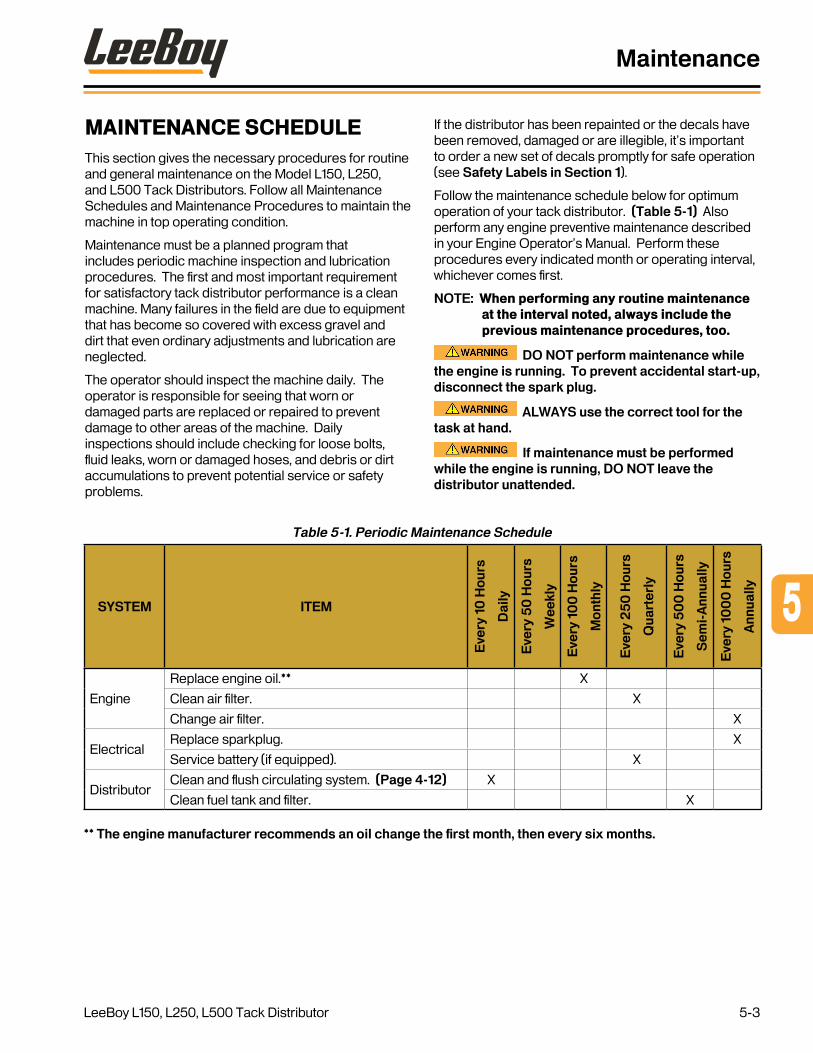
MAINTENANCE SCHEDULEThis section gives the necessary procedures for routine and general maintenance on the Model L150, L250, and L500 Tack Distributors. Follow all Maintenance Schedules and Maintenance Procedures to maintain the machine in top operating condition.
Maintenance must be a planned program that includes periodic machine inspection and lubrication procedures. The first and most important requirement for satisfactory tack distributor performance is a clean machine. Many failures in the field are due to equipment that has become so covered with excess gravel and dirt that even ordinary adjustments and lubrication are neglected.
The operator should inspect the machine daily. The operator is responsible for seeing that worn or damaged parts are replaced or repaired to prevent damage to other areas of the machine. Daily inspections should include checking for loose bolts, fluid leaks, worn or damaged hoses, and debris or dirt accumulations to prevent potential service or safety problems.
Table 5-1. Periodic Maintenance Schedule
SYSTEM ITEM
Eve
ry 1
0 H
our
s
Dai
ly
Eve
ry 5
0 H
our
s
Wee
kly
Eve
ry 1
00
Ho
urs
Mo
nthl
y
Eve
ry 2
50
Ho
urs
Qua
rter
ly
Eve
ry 5
00
Ho
urs
Sem
i-A
nnua
lly
Eve
ry 1
00
0 H
our
s
Ann
ually
Engine
Replace engine oil.** X
Clean air filter. X
Change air filter. X
ElectricalReplace sparkplug. X
Service battery (if equipped). X
DistributorClean and flush circulating system. (Page 4-12) X
Clean fuel tank and filter. X
** The engine manufacturer recommends an oil change the first month, then every six months.
If the distributor has been repainted or the decals have been removed, damaged or are illegible, it’s important to order a new set of decals promptly for safe operation (see Safety Labels in Section 1).
Follow the maintenance schedule below for optimum operation of your tack distributor. (Table 5-1) Also perform any engine preventive maintenance described in your Engine Operator’s Manual. Perform these procedures every indicated month or operating interval, whichever comes first.
NOTE: When performing any routine maintenance at the interval noted, always include the previous maintenance procedures, too.
DO NOT perform maintenance while the engine is running. To prevent accidental start-up, disconnect the spark plug.
ALWAYS use the correct tool for the task at hand.
If maintenance must be performed while the engine is running, DO NOT leave the distributor unattended.
5
Maintenance
LeeBoy L150, L250, L500 Tack Distributor 5-3

Preparing Tack Distributor for MaintenanceAlways take the following steps to prepare for preventive maintenance procedures:
1. Park the distributor on a flat even surface, preferably outside, or in a well-ventilated area.
2. Let the engine and exhaust system cool if needed.
3. Read the instructions before you begin, and make sure you have the proper tools.
DO NOT smoke or work near any sparks or open flame. Use only a non-flammable solvent to clean parts.
10-Hour or Daily Routine Maintenance1. Perform previous maintenance procedures.
2. Remove any debris from distributor and check for leaks.
3. Check oil level. Add more if needed.
4. Check fittings and tighten if needed.
5. Keep the fuel tank full to prevent condensation from forming.
6. Check air filter. Clean if needed.
7. Clean and flush circulating system. (Page 4-12)
8. Perform engine preventive maintenance as described in your Engine Operator’s Manual.
50-Hour (Initial) or Weekly Routine Maintenance1. Perform previous maintenance procedures.
2. Check all battery connections and remove any corrosion (if equipped).
3. Perform engine preventive maintenance as described in your Engine Operator’s Manual.
100-Hour or Monthly Routine Maintenance1. Perform previous maintenance procedures.
2. Clean air filter.
3. Perform any other engine preventive maintenance as described in the Engine Operator’s Manual.
250-Hour or Quarterly Routine Maintenance1. Perform previous maintenance procedures.
2. Check air cleaner.
3. Perform the 1000-hour preventive maintenance as described in the Engine Operator’s Manual.
500-Hour or Semi-Annual Routine Maintenance1. Perform previous maintenance procedures.
2. Change engine oil.
3. Clean fuel tank and filter.
4. Perform the 1000-hour preventive maintenance as described in the Engine Operator’s Manual.
1000-Hour or Annual Routine Maintenance1. Perform previous maintenance procedures.
2. Replace air filter.
3. Replace spark plug.
4. Check/adjust idle speed.
5. Check/adjust valve clearance.
6. Perform the 1000-hour preventive maintenance as described in the Engine Operator’s Manual.
Maintenance
LeeBoy L150, L250, L500 Tack Distributor5-4

ENGINE MAINTENANCEEngine maintenance is critical for maximizing safe and efficient operation. Inspect the engine routinely and perform the maintenance procedures at the appropriate intervals to enjoy years of trouble-free operation. For more specific engine maintenance information, see the Engine Operator’s Manual.
1 2 3
4
5
Figure 5-1. Engine Overview
1 - Tack Pump
2 - Gas Tank
3 - Muffler
4 - Air Filter Cover
5 - Oil Cap/Dipstick
Check Engine Oil LevelThe engine lubrication oil must be kept at a level above the ADD mark, but not above the FULL mark, on the engine lubrication oil dipstick. The dipstick is located under the oil filler cap. (Figure 5-1)
To accurately check the engine lubrication oil level:
1. Park the tack distributor on a level surface.
2. Remove the oil filler cap and wipe clean.
3. If the oil level is below the ADD mark, add oil, checking the level by reinserting the dipstick. DO NOT OVERFILL.
4. When filled to the correct level, reinstall oil filler cap.
Figure 5-2. Check Engine Oil Level
Running the engine when the oil level is too low will damage the engine.
Stop the engine before checking the engine lubrication oil level as hot oil can cause serious burns.
Change Engine Lubrication Oil DO NOT change the engine lubrication
oil when the engine is hot. Hot oil can be thrown and cause serious injury.
DO NOT change the engine lubrication oil while the engine is running as serious damage or engine failure can occur.
Drain the oil while the engine is warm as it will drain more quickly and completely. To change the oil:
1. Place a container that has sufficient capacity to hold the drained oil directly under the engine.
2. Remove oil drain plug.
3. Allow the used oil to drain completely.
4. Reinstall the oil drain plug.
5. Remove the oil fill cap.
6. Fill the engine with one (1) quarts (.94 liters) of oil.
7. Reinstall the filler cap.
8. Dispose of used oil in accordance with local and government environmental requirements, i.e., recycling center or service station facility.
5
Maintenance
LeeBoy L150, L250, L500 Tack Distributor 5-5

Change Engine Air FilterThe engine inlet air filter assembly uses a replaceable filter element. A dirty air cleaner restricts air flow and reduces engine performance, therefore, check and clean the air filter regularly. Replace the air filter every year or more if filter becomes damaged or too dirty.
Use the following procedures to change the air cleaner element:
1. Remove the cover on air breather housing. (Figure 5-1)
2. Remove the air filter element. (Figure 5-3)
AirFilter
Figure 5-3. Air Filter Element
3. Clean the inside of the air cleaner housing with a clean, lint-free cloth.
4. Discard filter properly.
5. Carefully install the new air filter elements into the housing.
6. Start the engine and check that it runs smoothly.
Replace the air filter element more often than indicated on the Maintenance Schedule (Page 5-3) if operating in dusty or more severe conditions. NEVER operate the engine without an air cleaner element installed.
NEVER operate the engine without an air cleaner element installed. Severe engine damage can occur if engine is operated without air filter or a filter improperly installed.
BURNER SYSTEMInspect the burners and mounting system daily for efficient and safe operation.
• Tighten, repair or replace any worn, damaged or malfunctioning components.
• Always fill up the fuel tank after use to prevent condensation in the tank.
• Check the tank valve, burner valves and fuel lines for leaks. If a leak is suspected, use soapy water to identify the source.
• Check the burning mounting hardware and tighten any components if needed.
• Inspect the flue tubes for cracks or other damage.
TRAILER-MOUNTED MODELSCheck tires for excessive wear, correct tire pressure and any damage regularly.
• Check tires and wheels for cuts, bubbles, damaged rims or missing wheel bolts or nuts.
• Protect tires from contact with petroleum products and chemicals.
• Check that lug nuts are tight.
DO NOT lift or support trailer on any part of the axle or suspension system.
Only use a jack and jack stand that has been rated for the unit’s weight. An improperly supported trailer can fall and cause serious injury or death.
Changing Tires1. Park distributor on a flat surface and place a block
or jack stand on each side of the tire not being replaced.
2. Raise the distributor using a tire jack on the frame near the tire being changed. DO NOT raise the frame too high.
3. Loosen and remove lug nuts.
4. Carefully remove tire.
5. Install replacement tire.
6. Replace lug nuts, tightening alternately. Torque to 85 ft. lbs. (115 Nm).
Maintenance
LeeBoy L150, L250, L500 Tack Distributor5-6

Brakes (L250 and L500 Models)The L250 and L500 models are equipped with electric brakes that should be adjusted after the first 200 miles of operation (after the brake shoes and drums have “seated”), and at 3,000-mile intervals. Adjustment may be needed more frequently if the unit is operated in more severe conditions.
Inspect your brakes periodically and clean the backing plate, magnet arm, magnet and brake shoes. Inspect and replace any damaged or worn parts. Before reassembling, apply a light film of grease or anti-seize compound on the brake anchor pin, arm bushing and pin and the backing plate where it contacts with brake shoes and the magnet lever arm.
Get brakes serviced immediately if any loss of performance is noted.
To adjust the brakes:
1. Jack up the trailer and secure as described in the Tire section above. Ensure the wheel and drum rotates freely.
2. Remove the cover from the adjusting slot on bottom of the brake backing plate.
3. Using a screwdriver or standard adjusting tool, rotate the star wheel of the adjuster assmebly to expand the brake shoes.
4. Adjust brake shoes until the pressure of the linings against the drum makes the wheel very difficult to turn.
5. Rotate the star wheel in the opposite direction until the wheel turns freely with a slight “drag.”
6. Replace the cover and lower trailer.
7. Repeat these steps on the other brake.
OPTIONAL COMPONENTS
Battery The optional battery for the electrical system is a 12-volt negative-ground system that provides power for the electric starter. It is contained in a hinged battery box and mounted on the trailer frame.
Figure 5-4. Battery
Keep the battery clean and wash it when dirt buildup is excessive. Be sure the terminals and battery posts are thoroughly cleaned and that battery cable terminals are tight. Dirty or loose connections can create high electrical resistance and permit arcing. Remove any corrosion around terminal connections and clean with ammonia or a solution of 1/4 lb. (.11 kg) baking soda in one quart of warm water. Ensure vent caps are tight to prevent solution from entering the cells. After cleaning, pour clean water over the battery and surrounding area to rinse away the solution. Check vent cap breather openings to make sure they are open.
Fire Hazard! Keep sparks and flames away from the batteries as electrolyte gas is highly flammable.
NOTE: When replacing the battery, discard the old battery properly.
5
Maintenance
LeeBoy L150, L250, L500 Tack Distributor 5-7

NOTE: Connect the positive (+) cable to the positive (+) post of the battery. Connect the ground cable to the negative (-) post of the battery. It is advisable to disconnect the negative (-) cable first and connect it last. Reversed polarity can damage the electrical system.
NEVER allow battery fluid to come into contact with clothing, skin or eyes. ALWAYS wear safety goggles and protective clothing when servicing the battery. If battery fluid contacts eyes or skin, immediately flush the affected areas with water and obtain prompt medical treatment.
Fire and Explosion Hazard! Be sure the battery charger is in the OFF position before connecting it to the battery.
Keep the battery fully charged during cold weather and when machine has been idle for extended periods. When connecting a booster battery, connect one end of the first jumper cable to the positive (+) terminal of the dead battery, and the other end to the positive (+) terminal of the booster battery. Connect one end of the second jumper cable to the negative (-) terminal of the booster battery and the other end to the frame of the distributor with the dead battery.
Fire and Explosion Hazard! Always observe battery polarity when connecting a battery charger or jumper cables to the battery: Negative (-) to negative (-); positive (+) to positive (+). Failure to follow this procedure can produce sparks.
STORAGEA stored unit requires periodic maintenance. If storing a tack distributor long-term, it’s important to prepare the unit first:
1. Clean the machine thoroughly and paint any chipped or rusty areas. DO NOT spray rust inhibitors on painted surfaces as many destroy the paint.
2. Inspect the unit thoroughly and replace any worn or damaged parts.
3. Top off all fluids to minimize condensation inside the tanks.
4. Inspect all hoses and fittings. Tighten or replace if needed.
5. Drain the tack tank and thoroughly flush the asphalt delivery lines.
6. If unit is equipped with an electric-start engine, remove the battery and store it in a cool, dry place.
7. Check safety decals. Replace any that are illegible or missing.
8. Place a DO NOT OPERATE sign on the machine.
9. Store unit in a dry, protected area. If stored outside, cover with waterproof material.
Maintenance
LeeBoy L150, L250, L500 Tack Distributor5-8
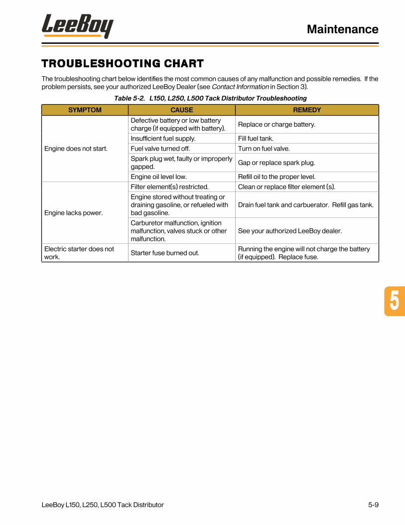
Troubleshooting ChartThe troubleshooting chart below identifies the most common causes of any malfunction and possible remedies. If the problem persists, see your authorized LeeBoy Dealer (see Contact Information in Section 3).
Table 5-2. L150, L250, L500 Tack Distributor Troubleshooting
SYMPTOM CAUSE REMEDY
Engine does not start.
Defective battery or low battery charge (if equipped with battery).
Replace or charge battery.
Insufficient fuel supply. Fill fuel tank.
Fuel valve turned off. Turn on fuel valve.
Spark plug wet, faulty or improperly gapped.
Gap or replace spark plug.
Engine oil level low. Refill oil to the proper level.
Engine lacks power.
Filter element(s) restricted. Clean or replace filter element (s).
Engine stored without treating or draining gasoline, or refueled with bad gasoline.
Drain fuel tank and carbuerator. Refill gas tank.
Carburetor malfunction, ignition malfunction, valves stuck or other malfunction.
See your authorized LeeBoy dealer.
Electric starter does not work.
Starter fuse burned out.Running the engine will not charge the battery (if equipped). Replace fuse.
5
Maintenance
LeeBoy L150, L250, L500 Tack Distributor 5-9

NOTES
Maintenance
LeeBoy L150, L250, L500 Tack Distributor5-10

LeeBoy L150, L250, L500 Tack Distributor 6-1
Page
Schematics . . . . . . . . . . . . . . . . . . . . . . . . . . . . . . . . . 6-1
Main Harness Assembly - L150/L250 Tack Tanks 6-3
Main Harness Assembly - L500 Tack Tank 6-5
LeeBoy L150, L250, L500 Tack Distributor
SCHEMATICS
Section 6

LeeBoy L150, L250, L500 Tack Distributor
Schematics
6-2

MAIN HARNESS ASSEMBLY - L150/L250 TACK TANKS
Schematic for Part # 1009625
Figure 6-1. Main Harness Assembly - L150/L250 Tack Tanks
YEL
WHT
BRN
WHT
BRN
GRN
BLU
WHT
RED
RED
WHTBRN
BRNWHT
6 AMP DIODE
WIRING COLOR CODESPOLE COLOR FUNCTION
1 WHITE GROUND RETURN2 BLUE ELECTRIC BRAKES3 BROWN TAIL, LICENSE & RUNNING LIGHTS
4 RED BATTERY CHARGE, IN CAB CONTROLS
5 YELLOW STOP & LEFT HAND TURN SIGNAL6 GREEN STOP & RIGHT HAND TURN SIGNAL7 N/A AUXILARY CIRCUIT
LeeBoy L150, L250, L500 Tack Distributor 6-3
Schematics

LeeBoy L150, L250, L500 Tack Distributor6-4
Schematics
NOTES

MAIN HARNESS ASSEMBLY - L500 TACK TANK
Schematic for Part # 1009766
Figure 6-2. Main Harness Assembly - L500 Tack Tank
RED
WHTBLU
GRNBRN
WHT
BRN
WHTYELWHT
BLU
BRN WHT
BRNWHT
6 AMP DIODERED
WIRING COLOR CODESPOLE COLOR FUNCTION
1 WHITE GROUND RETURN2 BLUE ELECTRIC BRAKES3 BROWN TAIL, LICENSE & RUNNING LIGHTS
4 RED BATTERY CHARGE, IN CAB CONTROLS
5 YELLOW STOP & LEFT HAND TURN SIGNAL6 GREEN STOP & RIGHT HAND TURN SIGNAL7 N/A AUXILARY CIRCUIT
LeeBoy L150, L250, L500 Tack Distributor 6-5
Schematics

LeeBoy L150, L250, L500 Tack Distributor6-6
Schematics
NOTES

Page
Illustrated Parts List . . . . . . . . . . . . . . . . . . . . . . . . . . . . . 7-1
Quick Reference 7-3
L150 Trailer Assembly 7-4
L150 Skid Assembly 7-6
L250 Trailer Assembly 7-8
L250 Skid Assembly 7-10
L500 Trailer Assembly 7-12
L500 Skid Assembly 7-14
L150 Hose Assemblies 7-16
L250 / L500 Hose Assemblies 7-18
Flush Tank System 7-20
Propane Tank Assembly 7-22
Engine and Pump Assembly 7-24
Lower Liquid Asphalt Valve Assembly 7-26
Selector and Spray Valve Assemblies 7-28
L150 Idler Axle Assembly 7-30
L250 / L500 Axle and Brake Assembly 7-32
Spray Bar Assembly (Option) 7-34
Alphabetical Parts Index 7-36
LeeBoy L150, L250, L500 Tack Distributor 7-1
ILLUSTRATED PARTS LIST
Section 7

NOTES
Illustrated Parts List
LeeBoy L150, L250, L500 Tack Distributor7-2

QUICK REFERENCE
STANDARD ENGINE
Description Part #
Air Filter 150200-01
Tack Tank Pump - 3 5 GPM 280020
Tack Tank Pump - 7 0 GPM 280020A
Pump Seal Kit 280020-1
BURNER SYSTEM
Description Part #
Propane Tank 230010-30
Burner Nozzle, Igniter 1008652SRV
Burner Nozzle 1008655SRV
LPG Pressure Gauge 230110
SPRAY SYSTEM
Description Part #
Hose Reel Assembly 150020
Spray Wand Nozzle 280310
Spray Bar Nozzle 280310
TRAILER MOUNT
Description Part #
Tire/Wheel Assembly 150090A
Brake Shoe Kit 340070
Specifications and designs may change without prior notice. These illustrations do not necessarily show the standard versions
7
Illustrated Parts List
LeeBoy L150, L250, L500 Tack Distributor 7-3

L150 TRAILER ASSEMBLY
Figure 7-1. L150 Trailer Assembly
18
15
17
212
12
13,19
10
5
9
14
48
3
16
11
6
1
7
20
22
23
Illustrated Parts List
LeeBoy L150, L250, L500 Tack Distributor7-4

L150 Trailer Assembly Parts List
Item No .
Part Number Qty . Description Remarks
1 150020 1 Hose Reel Assembly
2 280300 1 Drain Plug
3 851957SRV 1 Selector Valve Assembly See Page 7-29
4 1009919SRV 1 Lower Liquid Asphalt Valve Assembly See Page 7-27
5 230010-30 1 Propane Tank, 30#, LPG
6 - 1 Flush Tank System See Page 7-21
7 150230 1 Manifold, LPG
8 1008655SRV 2 Burner Nozzle See Page 7-23
9 982515 1 Gauge/Regulator, LPG
10 1008652SRV 1 Burner Nozzle, Igniter See Page 7-23
11 330040 1 Gauge, Temperature
12 280302 1 Wand, Tack Spray
13 1003098 1 Box, Battery Optional
14 150202SRV 1 Engine & Pump Assembly (Honda) See Page 7-25
15 280301 1 Plug, 2” NPT
16 150220 1 Jack Stand
17 150090A 2 Tire/Wheel Assembly
18 985187SRV 1 Spray Bar Assembly , 8 Ft Optional, See Page 7-35
19 Purchase Locally 1 Battery, 12V, 725 CCA Group 24 Optional
20 851941SRV 1 Spray Selector Valve Assembly, Trailer See Page 7-29
21 150040 1 Axle Assembly, Idler 3500# See Page 7-31
22 510200A 1 Coupler, 2” Ball, Adjustable
23 510200 1 Pintle Eye, 2-1/2” Optional
7
Illustrated Parts List
LeeBoy L150, L250, L500 Tack Distributor 7-5
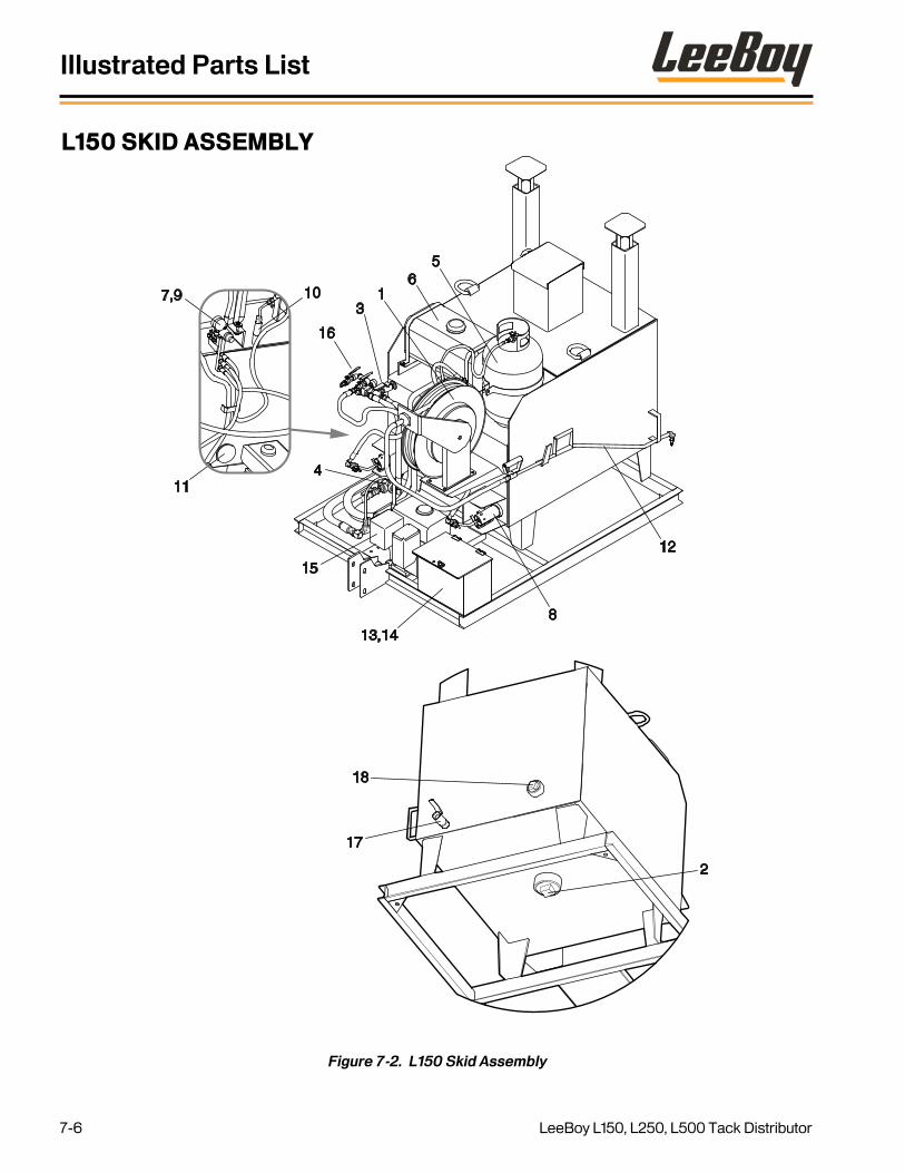
L150 SKID ASSEMBLY
Figure 7-2. L150 Skid Assembly
12
65
13
16
813,14
15
4
10
11
7,9
17
18
2
Illustrated Parts List
LeeBoy L150, L250, L500 Tack Distributor7-6

L150 Skid Assembly Parts List
Item No .
Part Number Qty . Description Remarks
1 150020 1 Hose Reel Assembly
2 280300 1 Drain Plug
3 851957SRV 1 Selector Valve Assembly See Page 7-29
4 1009919SRV 1 Lower Liquid Asphalt Valve Assembly See Page 7-27
5 230010-30 1 Propane Tank, 30#, LPG
6 - 1 Flush Tank System See Page 7-21
7 150230 1 Manifold, LPG
8 1008655SRV 2 Burner Nozzle See Page 7-23
9 982515 1 Gauge/Regulator, LPG
10 1008652SRV 1 Burner Nozzle, Igniter See Page 7-23
11 330040 1 Gauge, Temperature
12 280302 1 Wand, Tack Spray
13 150033 1 Battery Box Optional
14 Purchase Locally 1 Battery, 12V, 725 CCA Group 24 Optional
15 150202SRV 1 Engine & Pump Assembly (Honda) See Page 7-25
16 851967SRV 1 Spray Selector Valve, Skid See Page 7-29
17 280210 1 Ball Valve, 1 “
18 280301 1 Plug, 2” NPT
- 985187SRV 1 Spray Bar Assembly, 8 Ft , Skid Optional, Not Shown, See Page 7-35
7
Illustrated Parts List
LeeBoy L150, L250, L500 Tack Distributor 7-7

L250 TRAILER ASSEMBLY
Figure 7-3. L250 Trailer Assembly
18
21
17152
12
9
5
10
13,19
11
14
168
4
3
20
7
6
1
22
23
Illustrated Parts List
LeeBoy L150, L250, L500 Tack Distributor7-8

L250 Trailer Assembly Parts List
Item No .
Part Number Qty . Description Remarks
1 150020 1 Hose Reel Assembly
2 280300 1 Drain Plug
3 851957SRV 1 Selector Valve Assembly See Page 7-29
4 1009919SRV 1 Lower Liquid Asphalt Valve Assembly See Page 7-27
5 230010-30 1 Propane Tank, 30#, LPG
6 - 1 Flush Tank System See Page 7-21
7 150230 1 Manifold, LPG
8 1008655SRV 2 Burner Nozzle See Page 7-23
9 982515 1 Gauge/Regulator, LPG
10 1008652SRV 1 Burner Nozzle, Igniter See Page 7-23
11 330040 1 Gauge, Temperature
12 280302 1 Wand, Tack Spray
13 150033 1 Battery Box Optional
14 150202SRV 1 Engine & Pump Assembly (Honda) See Page 7-25
15 150040B 1 Axle Assembly, Brake 5200# See Page 7-33
16 150220 1 Jack Stand
17 150090A 2 Tire/Wheel Assembly
18 985187SRV 1 Spray Bar Assembly, 8 Ft , Trailer Optional, See Page 7-35
19 Purchase Locally 1 Battery, 12V, 725 CCA Group 24 Optional
20 851941SRV 1 Spray Selector Valve Assembly, Trailer See Page 7-29
21 280301 1 Plug, 2” NPT
22 510200A 1 Coupler, 2” Ball, Adjustable
23 510200 1 Pintle Eye, 2-1/2” Optional
7
Illustrated Parts List
LeeBoy L150, L250, L500 Tack Distributor 7-9

L250 SKID ASSEMBLY
Figure 7-4. L250 Skid Assembly
6
5
10
1
13,14
11
154
8
3
16
12
18
17
2
7,9
Illustrated Parts List
LeeBoy L150, L250, L500 Tack Distributor7-10

L250 Skid Assembly Parts List
Item No .
Part Number Qty . Description Remarks
1 150020 1 Hose Reel Assembly
2 280300 1 Drain Plug
3 851957SRV 1 Selector Valve Assembly See Page 7-29
4 1009919SRV 1 Lower Liquid Asphalt Valve Assembly See Page 7-27
5 230010-30 1 Propane Tank, 30#, LPG
6 - 1 Flush Tank System See Page 7-21
7 150230 1 Manifold, LPG
8 1008655SRV 2 Burner Nozzle See Page 7-23
9 982515 1 Gauge/Regulator, LPG
10 1008652SRV 1 Burner Nozzle, Igniter See Page 7-23
11 330040 1 Gauge, Temperature
12 280302 1 Wand, Tack Spray
13 150033 1 Battery Box Optional
14 Purchase Locally 1 Battery, 12V, 725 CCA Group 24 Optional
15 150202SRV 1 Engine & Pump Assembly (Honda) See Page 7-25
16 851967SRV 1 Spray Selector Valve, Skid See Page 7-29
17 280210 1 Ball Valve, 1”
18 280301 1 Plug, 2” NPT
- 985187SRV 1 Spray Bar Assembly, 8 Ft , Skid Optional, Not Shown, See Page 7-35
7
Illustrated Parts List
LeeBoy L150, L250, L500 Tack Distributor 7-11

L500 TRAILER ASSEMBLY
Figure 7-5. L500 Trailer Assembly
1
5
6
10
9
711
8
15
13,14
20
21
22
4
3
19
17
28
23 18
24
12
16
Illustrated Parts List
LeeBoy L150, L250, L500 Tack Distributor7-12

L500 Trailer Assembly Parts List
Item No .
Part Number Qty . Description Remarks
1 150020 1 Hose Reel Assembly
2 280300 1 Drain Plug
3 851957SRV 1 Selector Valve Assembly See Page 7-29
4 1009919SRV 1 Lower Liquid Asphalt Valve Assembly See Page 7-27
5 230010-30 1 Propane Tank, 30#, LPG
6 - 1 Flush Tank System See Page 7-21
7 150230 1 Manifold, L PG
8 1008655SRV 2 Burner Nozzle See Page 7-23
9 982515 1 Gauge/Regulator, LPG
10 1008652SRV 1 Burner Nozzle, Igniter See Page 7-23
11 330040 1 Gauge, Temperature
12 280302 1 Wand, Tack Spray
13 150033 1 Battery Box Optional
14 Purchase Locally 1 Battery, 12V, 725 CCA Group 24 Optional
15 150202SRV 1 Engine & Pump Assembly (Honda) See Page 7-23
16 985188SRV 1 Spray Bar Assembly, 8’, Trailer See Page 7-35
17 150710SRV 1 Heater, Electric 120V
18 280210 1 Ball Valve, 1”
19 851941SRV 1 Spray Selector Valve Assembly, Trailer See Page 7-29
20 150220A 1 Jack Stand
21 510200 1 Pintle Eye, 2-1/2”
22 510200A 1 Coupler, 2” Ball, Adjustable Option
23 150040B 2 Axle Assembly, Brake 5200# See Page 7-33
24 150090A 4 Tire/Wheel Assembly
7
Illustrated Parts List
LeeBoy L150, L250, L500 Tack Distributor 7-13

L500 SKID ASSEMBLY
Figure 7-6. L500 Skid Assembly
5
9
6
10
1
13,14
1511
4
8
3
16
12
7
1718
2Shown without electric heater.Item 18 used to cap heater port.
Illustrated Parts List
LeeBoy L150, L250, L500 Tack Distributor7-14
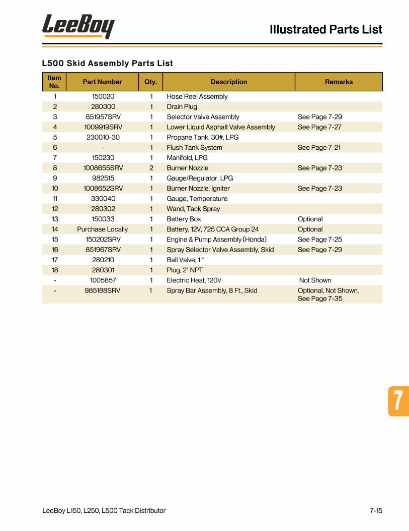
L500 Skid Assembly Parts List
Item No .
Part Number Qty . Description Remarks
1 150020 1 Hose Reel Assembly
2 280300 1 Drain Plug
3 851957SRV 1 Selector Valve Assembly See Page 7-29
4 1009919SRV 1 Lower Liquid Asphalt Valve Assembly See Page 7-27
5 230010-30 1 Propane Tank, 30#, LPG
6 - 1 Flush Tank System See Page 7-21
7 150230 1 Manifold, LPG
8 1008655SRV 2 Burner Nozzle See Page 7-23
9 982515 1 Gauge/Regulator, LPG
10 1008652SRV 1 Burner Nozzle, Igniter See Page 7-23
11 330040 1 Gauge, Temperature
12 280302 1 Wand, Tack Spray
13 150033 1 Battery Box Optional
14 Purchase Locally 1 Battery, 12V, 725 CCA Group 24 Optional
15 150202SRV 1 Engine & Pump Assembly (Honda) See Page 7-25
16 851967SRV 1 Spray Selector Valve Assembly, Skid See Page 7-29
17 280210 1 Ball Valve, 1 “
18 280301 1 Plug, 2” NPT
- 1005857 1 Electric Heat, 120V Not Shown
- 985188SRV 1 Spray Bar Assembly, 8 Ft , Skid Optional, Not Shown, See Page 7-35
7
Illustrated Parts List
LeeBoy L150, L250, L500 Tack Distributor 7-15
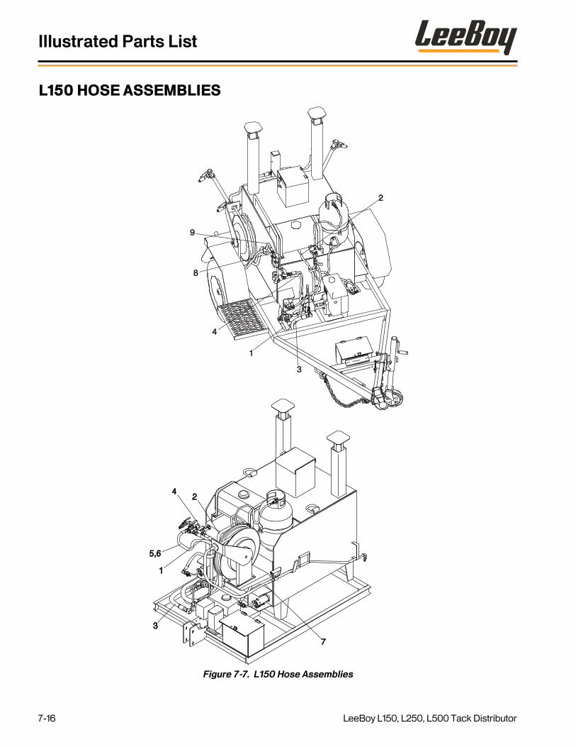
L150 HOSE ASSEMBLIES
Figure 7-7. L150 Hose Assemblies
2
3
1
4
9
8
2
5,6
3
1
4
7
Illustrated Parts List
LeeBoy L150, L250, L500 Tack Distributor7-16

L150 Hose Assemblies Parts List
Item No .
Part Number Qty . Description Remarks
1 150026 1 Hose Assembly, Tank Valve Return To Liquid Valve
2 230290 1 Hose Assembly, Flush Tank
3 150028 1 Hose Assembly, Tack Pump Feed
4 150027 1 Hose Assembly, Relief Valve To Upper Tank Valve
5 150030 1 Hose Assembly, Upper Valve To Hose Reel (Skid Only)
6 X161 1 Adapter, Hose To Pipe (Skid Only) Not Shown
7 280110 1 Hose, Hose Reel
8 150021 1 Hose, Selector Valve To Hose Reel
9 150022 1 Hose, Selector Valve To Spray Bar
7
Illustrated Parts List
LeeBoy L150, L250, L500 Tack Distributor 7-17

L250 / L500 HOSE ASSEMBLIES
Figure 7-8. L250/L500 Hose Assemblies
2
13
8
9
4
3 2
7
6
4
5
1
Illustrated Parts List
LeeBoy L150, L250, L500 Tack Distributor7-18

L250 / L500 Hose Assemblies Parts List
Item No .
Part Number Qty . Description Remarks
1 150026 1 Hose Assembly, Tank Valve Return To Liquid Valve
2 230290 1 Hose Assembly, Flush Tank
3 150028 1 Hose Assembly, Tack Pump Feed
4 150027 1 Hose Assembly, Relief Valve To Upper Tank Valve
5 150030 1 Hose Assembly, Upper Valve To Hose Reel (Skid Only)
6 X161 1 Adapter, Hose To Pipe (Skid Only)
7 280110 1 Hose, Hose Reel
8 150021 1 Hose, Selector Valve To Hose Reel
9 150022 1 Hose, Selector Valve To Spray Bar
7
Illustrated Parts List
LeeBoy L150, L250, L500 Tack Distributor 7-19

FLUSH TANK SYSTEM
Figure 7-9. Flush Tank System
1
2,3,46
5
Illustrated Parts List
LeeBoy L150, L250, L500 Tack Distributor7-20

Flush Tank System
Item No .
Part Number Qty . Description Remarks
1 988731 1 Flush Tank, 7 Gallon
2 140030FL 1 Fuel Tank Cap, Lockable
3 140030FN 1 Fuel Cap Filler Neck
4 853930 1 Breather Cap Filler Gasket
5 851879 2 Flush Tank Strap
6 230290 1 Hose Assembly, Flush Tank
7
Illustrated Parts List
LeeBoy L150, L250, L500 Tack Distributor 7-21
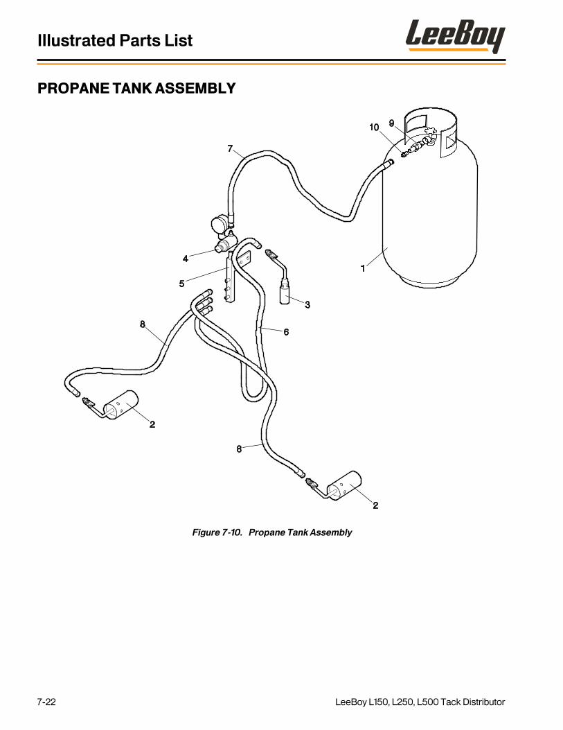
PROPANE TANK ASSEMBLY
Figure 7-10. Propane Tank Assembly
910
7
4
5
8
3
6
1
8
2
2
Illustrated Parts List
LeeBoy L150, L250, L500 Tack Distributor7-22

Propane Tank Assembly Parts List
Item No .
Part Number Qty . Description Remarks
1 230010-30 1 Propane Tank, 30#, LPG
2 1008655SRV 2 Burner Nozzle
3 1008652SRV 1 Burner Nozzle, Igniter
4 982515 1 Gauge/Regulator, LPG
5 150230 1 Manifold, LPG
6 230260 1 Hose Assembly, LPG Igniter
7 230270 1 Hose Assembly, LPG Tank to Regulator
8 230280 2 Hose Assembly, LPG Manifold to Burner Nozzle
9 230030 1 Adapter, LPG Tank
10 230250 1 Adapter, 1/4” LP Gas
7
Illustrated Parts List
LeeBoy L150, L250, L500 Tack Distributor 7-23

ENGINE AND PUMP ASSEMBLY
Figure 7-11. Engine and Pump Assembly
12
34
57
6
8
9
10
6
11
12,13
14
Illustrated Parts List
LeeBoy L150, L250, L500 Tack Distributor7-24

Engine and Pump Assembly Parts List
Item No .
Part Number Qty . Description Remarks
GRP 150202SRV Engine & Pump Assembly (Honda)
1 150200H 1 Engine, Honda 5 5 HP
2 150160 1 Adapter, Pump to Engine
3 150150A 1 Coupling Half, 5 5 HP Engine
4 280040 1 Insert, 3 Jaw Coupling
5 280050 1 Coupling Half, Tack Pump
6 2501-12-8 2 Adapter, Pipe To Hose (90 Degrees)
7 34688 1 Adapter, Pipe To Hose (Tee)
8 280020A 1 Pump, Tack Spray (7 GPM)
9 280075 1 Pipe, Nipple, 1/2” x 2 50
10 280100 1 Valve, Relief, 250 PSI
11 851945SRV 1 Bypass Assembly
12 100-5-18-16-5 4 CSHH, 5/16-18 x 1 00, GR5
13 302-5 4 Washer, Lock, 5/16
14 31898 1 Key Stock, Square, 3/16 x 1 50
- 280020-1 1 Seal Kit, Tack Pump Not Shown
- 280020-2SRV 1 Bushing/Bearing Kit, Tack Pump Not Shown
GRP - ELECTRIC START PARTS Not Shown
- 150200HE 1 Engine, Honda, 5 5 HP, Electric Start Option
- Purchase Locally 1 Battery, 12V 725 CCA Group 24 Option
- 800076 1 Cable, Battery, Negative, 26”, Eye/Eye Option
- 851465 1 Cable, Battery, Positive, 36”, Eye/Post Option
- 720130 1 Pad, Battery Tray Option
- 150042SRV 1 Strap, Battery Hold Down Option
7
Illustrated Parts List
LeeBoy L150, L250, L500 Tack Distributor 7-25

LOWER LIQUID ASPHALT VALVE ASSEMBLY
Figure 7-12. Lower Liquid Asphalt Valve Assembly
1
23
4
65
7
89
101112
1
1
13
Illustrated Parts List
LeeBoy L150, L250, L500 Tack Distributor7-26

Lower Liquid Asphalt Valve Assembly Parts List
Item No .
Part Number Qty . Description Remarks
GRP 1009919SRV Lower Liquid Asphalt Valve Assembly
1 91277 3 Nipple, Close, 1“ Pipe
2 853720 1 Valve, Ball, 3-Way, 1”,
3 2404-12-16 1 Adapter, Pipe to Hose
4 150028 1 Hose Assembly, Tack Pump Feed
5 2501-8-16 1 Adapter, Elbow (90 Degree)
6 150026 1 Hose Assembly, Tank Valve Return to Valve
7 230290 1 Hose Assembly, Flush Tank
8 32874 1 Ball Valve, 1/2”
9 99834 1 Nipple, Close, 1/2”
10 1009925 1 Bushing, Pipe, 1” x 1/2”
11 280230 1 Cross, 1” FNPT
12 1009924 1 Plug, Pipe, 1” MNPT
13 91278 1 Elbow, Pipe, 1” (90 Degree)
7
Illustrated Parts List
LeeBoy L150, L250, L500 Tack Distributor 7-27

SELECTOR AND SPRAY VALVE ASSEMBLIES
Figure 7-13. Selector and Spray Valve Assemblies
3
4
6
22
5
7
34
4
3
2
6
5
2
6
2
34
1
2
34
2
4
5
4
Selector Valve Assembly
Spray Selector Valve Assembly - Trailer
Spray Selector Valve Assembly - Skid
Illustrated Parts List
LeeBoy L150, L250, L500 Tack Distributor7-28

Selector and Spray Valve Assemblies Parts List
Item No .
Part Number Qty . Description Remarks
GRP 851957SRV Selector Valve Assembly Complete Assembly
1 910080 1 Valve, Selector
2 280270 2 Nipple, 1/2” Pipe
3 32874 1 Ball Valve, 1/2”
4 2404-8-8 3 Adapter, Pipe to Hose
5 99569 2 Tee, 1/2” Pipe
GRP 851941SRV Spray Selector Valve Assembly, Trailer Complete Assembly
2 280270 2 Nipple, 1/2” Pipe
3 32874 2 Ball Valve, 1/2”
4 2404-8-8 2 Adapter, Pipe to Hose
5 99569 1 Tee, 1/2” Pipe
6 99526 1 Elbow, Street 1/2”
7 280090 1 Nipple, 1/2” x 5 1/2” Long
GRP 851967SRV Spray Selector Valve Assembly, Skid Complete Assembly
2 280270 3 Nipple, 1/2” Pipe
3 32874 2 Ball Valve, 1/2”
4 2404-8-8 2 Adapter, Pipe to Hose
5 99569 1 Tee, 1/2” Pipe
6 99526 2 Elbow, Street 1/2”
7
Illustrated Parts List
LeeBoy L150, L250, L500 Tack Distributor 7-29

L150 IDLER AXLE ASSEMBLY
Figure 7-14. L150 Idler Axle Assembly
8
14
3
13
12
2
6,9
4,57
110
11
Illustrated Parts List
LeeBoy L150, L250, L500 Tack Distributor7-30

L150 Idler Axle Assembly Parts List
Item No .
Part Number Qty . Description Remarks
GRP 150040 Axle Assembly, Idler 3500# Complete Assembly
1 150040-1 2 Wheel Hub Assembly Includes items 3 thru 10
2 150830 1 Cup, Roller Bearing
3 150840 1 Cone, Roller Bearing
4 150430 1 Cup, Roller Bearing
5 150440 1 Cone, Roller Bearing
6 120340 6 Wheel Stud
7 150420 1 Wheel Seal, 3500#
8 150850 1 Grease Cap, 3500#
9 620520 6 Lug Nut
10 150060 2 Spring, Axle 3500#
11 150050 2 U-Bolt Kit 3500#
12 610260 2 Axle Nut
13 610250-1 2 D-Washer
14 610250 2 Lockwasher
7
Illustrated Parts List
LeeBoy L150, L250, L500 Tack Distributor 7-31

L250 / L500 AXLE AND BRAKE ASSEMBLY
Figure 7-15. L250 / L500 Axle and Brake Assembly
4,7
6
18
17
19
2
3
8,9
1413
12
11
20
5
10
16
1
15
Illustrated Parts List
LeeBoy L150, L250, L500 Tack Distributor7-32

L250 / L500 Axle and Brake Assembly Parts List
Item
No .Part Number Qty . Description Remarks
GRP 150040B Axle Assembly, Brake 5200#
1 317030 2 Brake Drum Assembly, 5200# Includes items 3 thru 10
2 610230 1 Cup, Roller Bearing
3 610240 1 Cone, Roller Bearing
4 120340 6 Wheel Stud
5 610190 1 Wheel Seal 5200#
6 340040 1 Grease Cap 5200#
7 620520 6 Lug Nut
8 610200 1 Cup, Roller Bearing
9 610210 1 Cone, Roller Bearing
10 340060R 1 Brake Assembly 5200R Includes items 13 thru 15
11 340060L 1 Brake Assembly 5200L Includes items 13 thru 15
12 340070 2 Brake Shoe Kit 12 X 2
13 340110 1 Brake Adjuster
14 340100 1 Electromagnet
15 150060A 2 Spring, Axle 5200#
16 150050A 2 U-Bolt Kit 5200#
17 610260 2 Axle Nut
18 610250-1 2 D-Washer
19 610250 2 Lockwasher
20 340130 2 Spring Kit
7
Illustrated Parts List
LeeBoy L150, L250, L500 Tack Distributor 7-33

SPRAY BAR ASSEMBLY (OPTION)
Figure 7-16. Spray Bar (Option)
89
10
1112
13
14
15
5 4
12
16
18
17
6,7
19,20
3
Illustrated Parts List
LeeBoy L150, L250, L500 Tack Distributor7-34
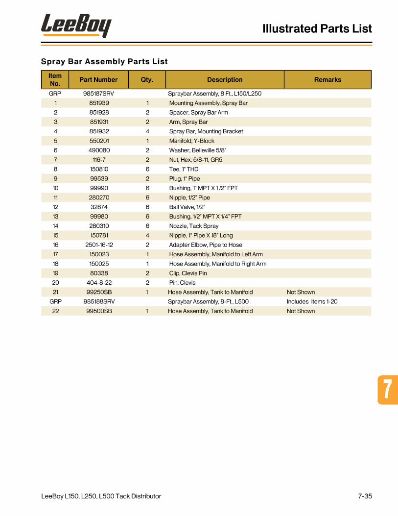
Spray Bar Assembly Parts List
Item No .
Part Number Qty . Description Remarks
GRP 985187SRV Spraybar Assembly, 8 Ft , L150/L250
1 851939 1 Mounting Assembly, Spray Bar
2 851928 2 Spacer, Spray Bar Arm
3 851931 2 Arm, Spray Bar
4 851932 4 Spray Bar, Mounting Bracket
5 550201 1 Manifold, Y-Block
6 490080 2 Washer, Belleville 5/8”
7 116-7 2 Nut, Hex, 5/8-11, GR5
8 150810 6 Tee, 1“ THD
9 99539 2 Plug, 1“ Pipe
10 99990 6 Bushing, 1“ MPT X 1 /2” FPT
11 280270 6 Nipple, 1/2” Pipe
12 32874 6 Ball Valve, 1/2“
13 99980 6 Bushing, 1/2” MPT X 1/4” FPT
14 280310 6 Nozzle, Tack Spray
15 150781 4 Nipple, 1“ Pipe X 18” Long
16 2501-16-12 2 Adapter Elbow, Pipe to Hose
17 150023 1 Hose Assembly, Manifold to Left Arm
18 150025 1 Hose Assembly, Manifold to Right Arm
19 80338 2 Clip, Clevis Pin
20 404-8-22 2 Pin, Clevis
21 99250SB 1 Hose Assembly, Tank to Manifold Not Shown
GRP 985188SRV Spraybar Assembly, 8-Ft , L500 Includes Items 1-20
22 99500SB 1 Hose Assembly, Tank to Manifold Not Shown
7
Illustrated Parts List
LeeBoy L150, L250, L500 Tack Distributor 7-35

ALPHABETICAL PARTS INDEX
Description Pa r t N umber Figure # Item #
-A-
Adapter, 1/4” LP Gas 230250 7-10 10
Adapter, Elbow (90 Degree) 2501-8-16 7-12 5
Adapter, Elbow, Pipe to Hose 2501-16-12 7-16 16
Adapter, Hose To Pipe (Skid Only) X161 7-8 6
Adapter, Hose To Pipe (Skid Only) X161 7-7 6
Adapter, LPG Tank 230030 7-10 9
Adapter, Pipe to Hose 2404-8-8 7-13 4
Adapter, Pipe to Hose 2404-8-8 7-13 4
Adapter, Pipe to Hose 2404-8-8 7-13 4
Adapter, Pipe to Hose 2404-12-16 7-12 3
Adapter, Pipe To Hose (90 Degrees) 2501-12-8 7-11 11
Adapter, Pipe To Hose (90 Degrees) 2501-12-8 7-11 6
Adapter, Pipe To Hose (Tee) 34688 7-11 7
Adapter, Pump to Engine 150160 7-11 2
Arm, Spray Bar 851931 7-16 3
Axle Assembly, Brake 5200# 150040B 7-15 GRP
Axle Assembly, Brake 5200# 150040B 7-5 25
Axle Assembly, Brake 5200# 150040B 7-3 15
Axle Assembly, Idler 3500# 150040 7-14 GRP
Axle Assembly, Idler 3500# 150040 7-1 22
Axle Nut 610260 7-15 17
Axle Nut 610260 7-14 12
-B-
Ball Valve, 1/2" 32874 7-16 12
Ball Valve, 1/2” 32874 7-13 3
Ball Valve, 1/2” 32874 7-13 3
Ball Valve, 1/2” 32874 7-13 3
Ball Valve, 1/2” 32874 7-12 8
Ball Valve, 1“ 280210 7-6 17
Ball Valve, 1” 280210 7-5 18
Ball Valve, 1” 280210 7-4 17
Ball Valve, 1“ 280210 7-2 17
Alphabetical Parts Index
LeeBoy L150, L250, L500 Tack Distributor7-36

Description Pa r t N umber Figure # Item #
Battery Box 150033 7-6 13
Battery Box 150033 7-5 13
Battery Box 150033 7-4 13
Battery Box 150033 7-3 13
Battery Box 150033 7-2 13
Battery Box 1003098 7-1 13
Battery, 12V 725 CCA Group 24 Purchase Locally 7-6 14
Battery, 12V 725 CCA Group 24 Purchase Locally 7-5 14
Battery, 12V 725 CCA Group 24 Purchase Locally 7-4 14
Battery, 12V 725 CCA Group 24 Purchase Locally 7-3 20
Battery, 12V 725 CCA Group 24 Purchase Locally 7-2 14
Battery, 12V 725 CCA Group 24 Purchase Locally 7-1 20
Battery, 12V 725 CCA Group 24 Purchase Locally 7-11 -
Brake Adjuster 340110 7-15 13
Brake Assembly 5200L 340060L 7-15 11
Brake Assembly 5200R 340060R 7-15 10
Brake Drum Assembly, 5200# 317030 7-15 1
Brake Shoe Kit 12 X 2 340070 7-15 12
Breather Cap Filler Gasket 853930 7-21 4
Burner Nozzle, Igniter 1008652SRV 7-10 3
Burner Nozzle, Igniter 1008652SRV 7-6 10
Burner Nozzle, Igniter 1008652SRV 7-5 10
Burner Nozzle, Igniter 1008652SRV 7-4 10
Burner Nozzle, Igniter 1008652SRV 7-3 10
Burner Nozzle, Igniter 1008652SRV 7-2 10
Burner Nozzle, Igniter 1008652SRV 7-1 10
Burner Nozzle 1008655SRV 7-10 2
Burner Nozzle 1008655SRV 7-6 8
Burner Nozzle 1008655SRV 7-5 8
Burner Nozzle 1008655SRV 7-4 8
Burner Nozzle 1008655SRV 7-3 8
Burner Nozzle 1008655SRV 7-2 8
Burner Nozzle 1008655SRV 7-1 8
Bushing, 1" MPT x 1 /2" FPT 99990 7-16 10
7
Alphabetical Parts Index
LeeBoy L150, L250, L500 Tack Distributor 7-37

Description Pa r t N umber Figure # Item #
Bushing, 1/2" MPT x 1/4" FPT 99980 7-16 13
Bushing, Pipe, 1” x 1/2” 1009925 7-12 10
Bushing/Bearing Kit, Tack Pump 280020-2SRV 7-11 -
Bypass Assembly 851945 7-11 12
-C-
Cable, Battery, Negative, 26”, Eye/Eye 800076 7-11 -
Cable, Battery, Positive, 36”, Eye/Post 851465 7-11 -
Clip, Clevis Pin 80338 7-16 19
Cone, Roller Bearing 610240 7-15 3
Cone, Roller Bearing 610210 7-15 9
Cone, Roller Bearing 150840 7-14 3
Cone, Roller Bearing 150440 7-14 5
Coupler, 2” Ball, Adjustable 510200A 7-1 23
Coupler, 2” Ball, Adjustable 510200A 7-5 24
Coupler, 2” Ball, Adjustable 510200A 7-3 23
Coupling Half, 5 5 HP Engine 150150A 7-11 3
Coupling Half, Tack Pump 280050 7-11 5
Cross, 1” FNPT 280230 7-12 11
CSHH, 5/16-18 x 1, GR5 100-5-18-16-5 7-11 13
Cup, Roller Bearing 610230 7-15 2
Cup, Roller Bearing 610200 7-15 8
Cup, Roller Bearing 150830 7-14 2
Cup, Roller Bearing 150430 7-14 4
-D-
Drain Plug 280300 7-6 2
Drain Plug 280300 7-5 2
Drain Plug 280300 7-4 2
Drain Plug 280300 7-3 2
Drain Plug 280300 7-2 2
Drain Plug 280300 7-1 2
D-Washer 610250-1 7-15
D-Washer 610250-1 7-14 18
-E-
Elbow, Pipe, 1” (90 Degree) 91278 7-12 13
Elbow, Street 1/2” 99526 7-13 6
Alphabetical Parts Index
LeeBoy L150, L250, L500 Tack Distributor7-38

Description Pa r t N umber Figure # Item #
Elbow, Street 1/2” 99526 7-13 6
Electric Heat, 120V (Option - Not Shown) 1005857 7-6 -
Electro-Magnet 340100 7-15 14
Engine & Pump Assembly (Honda) 150202SRV 7-6 15
Engine & Pump Assembly (Honda) 150202SRV 7-5 15
Engine & Pump Assembly (Honda) 150202SRV 7-4 15
Engine & Pump Assembly (Honda) 150202SRV 7-3 14
Engine & Pump Assembly (Honda) 150202SRV 7-2 15
Engine & Pump Assembly (Honda) 150202SRV 7-1 14
Engine, Honda 5 5 HP 150200H 7-11 1
Engine, Honda, 5 5 HP, Electric Start 150200HE 7-11 -
-F-
Flush Tank, 7 Gallon 988731 7-21 1
Flush Tank Strap 851879 7-21 5
Flush Tank System - 7-6 6
Flush Tank System - 7-5 6
Flush Tank System - 7-4 6
Flush Tank System - 7-3 6
Flush Tank System - 7-2 6
Flush Tank System - 7-1 6
Fuel Cap Filler Neck 140030FN 7-21 3
Fuel Tank Cap, Lockable 140030FL 7-21 2
-G-
Gauge, Temperature 330040 7-6 11
Gauge, Temperature 330040 7-5 11
Gauge, Temperature 330040 7-4 11
Gauge, Temperature 330040 7-3 11
Gauge, Temperature 330040 7-2 11
Gauge, Temperature 330040 7-1 11
Gauge/Regulator, LPG 952515 7-10 4
Gauge/Regulator, LPG 982515 7-5 9
Gauge/Regulator, LPG 982515 7-1 9
Gauge/Regulator, LPG 982515 7-6 9
Gauge/Regulator, LPG 982515 7-4 9
Gauge/Regulator, LPG 982515 7-3 9
7
Alphabetical Parts Index
LeeBoy L150, L250, L500 Tack Distributor 7-39

Description Pa r t N umber Figure # Item #
Gauge/Regulator, LPG 982515 7-2 9
Grease Cap, 3500# 150850 7-14 8
Grease Cap, 5200# 340040 7-15 6
-H-
Heater, Electric 120V 150710SRV 7-5 17
Hose Assembly, Distributor Valve To Hose Reel 150021 7-5 19
Hose Assembly, Distributor Valve To Spray Bar 150022 7-5 20
Hose Assembly, Flush Tank 230290 7-12 7
Hose Assembly, Flush Tank 230290 7-21 6
Hose Assembly, Flush Tank 230290 7-8 2
Hose Assembly, Flush Tank 230290 7-7 2
Hose Assembly, LPG Igniter 230260 7-10 6
Hose Assembly, LPG Manifold to Burner Nozzle 230280 7-10 8
Hose Assembly, LPG Tank to Regulator 230270 7-10 7
Hose Assembly, Manifold to Left Arm 150023 7-16 17
Hose Assembly, Manifold to Right Arm 150025 7-16 18
Hose Assembly, Relief Valve To Upper Tank Valve 150027 7-8 4
Hose Assembly, Relief Valve To Upper Tank Valve 150027 7-7 4
Hose Assembly, Tack Pump Feed 150028 7-12 4
Hose Assembly, Tack Pump Feed 150028 7-8 3
Hose Assembly, Tack Pump Feed 150028 7-7 3
Hose Assembly, Tank to Manifold, L150/L250 99250SB 7-16 21
Hose Assembly, Tank to Manifold, L500 99500SB 7-16 22
Hose Assembly, Tank Valve Return To Liquid Valve 150026 7-8 1
Hose Assembly, Tank Valve Return To Liquid Valve 150026 7-7 1
Hose Assembly, Tank Valve Return to Valve 150026 7-12 6
Hose Assembly, Upper Valve To Hose Reel (Skid Only) 150030 7-8 5
Hose Assembly, Upper Valve To Hose Reel (Skid Only) 150030 7-7 5
Hose Reel Assembly 150020 7-6 1
Hose Reel Assembly 150020 7-5 1
Hose Reel Assembly 150020 7-4 1
Hose Reel Assembly 150020 7-3 1
Hose Reel Assembly 150020 7-2 1
Hose Reel Assembly 150020 7-1 1
Alphabetical Parts Index
LeeBoy L150, L250, L500 Tack Distributor7-40

Description Pa r t N umber Figure # Item #
Hose, Hose Reel 280110 7-8 7
Hose, Hose Reel 280110 7-7 7
Hose, Selector Valve To Hose Reel 150021 7-8 8
Hose, Selector Valve To Hose Reel 150021 7-7 8
Hose, Selector Valve To Spray Bar 150022 7-8 9
Hose, Selector Valve To Spray Bar 150022 7-7 9
-I-
Insert, 3 Jaw Coupling 280040 7-11 4
-J-
Jack Stand 150220A 7-5 22
Jack Stand 150220 7-3 16
Jack Stand 150220 7-1 16
-K-
Key Stock, Square, 3/16 x 1 50 31898 7-11 14
-L-
Lockwasher 610250 7-15 19
Lockwasher 610250 7-14 14
Lower Liquid Asphalt Valve Assembly 1009919SRV 7-6 4
Lower Liquid Asphalt Valve Assembly 1009919SRV 7-5 4
Lower Liquid Asphalt Valve Assembly 1009919SRV 7-4 4
Lower Liquid Asphalt Valve Assembly 1009919SRV 7-3 4
Lower Liquid Asphalt Valve Assembly 1009919SRV 7-2 4
Lower Liquid Asphalt Valve Assembly 1009919SRV 7-1 4
Lug Nut 620520 7-15 7
Lug Nut 620520 7-14 9
-M-
Manifold, LPG 150230 7-5 7
Manifold, LPG 150230 7-10 5
Manifold, LPG 150230 7-1 7
Manifold, LPG 150230 7-6 7
Manifold, LPG 150230 7-4 7
Manifold, LPG 150230 7-3 7
Manifold, LPG 150230 7-2 7
Manifold, Y-Block 550201 7-16 5
7
Alphabetical Parts Index
LeeBoy L150, L250, L500 Tack Distributor 7-41

Description Pa r t N umber Figure # Item #
Mounting Assembly, Spray Bar 851939 7-16 1
-N-
Nipple, 1" Pipe x 18" Long 150781 7-16 15
Nipple, 1/2" Pipe 280270 7-16 11
Nipple, 1/2” Pipe 280270 7-13 2
Nipple, 1/2” Pipe 280270 7-13 2
Nipple, 1/2” Pipe 280270 7-13 2
Nipple, 1/2” x 5 1/2” Long 280090 7-13 7
Nipple, Close, 1/2” 99834 7-12 9
Nipple, Close, 1“ Pipe 91277 7-12 1
Nozzle, Tack Spray 280310 7-16 14
Nut, Hex, 5/8-11, GR5 116-7 7-16 7
-P-
Pad, Battery Tray 720130 7-11 -
Pin, Clevis 404-8-22 7-16 20
Pintle Eye, 2-1/2” 510200 7-3 24
Pintle Eye, 2-1/2” 510200 7-5 23
Pintle Eye, 2-1/2” 510200 7-1 24
Pipe, Nipple, 1/2 x 2 50 280075 7-11 9
Plug, Pipe, 1” MNPT 1009924 7-12 12
Plug, 1 " Pipe 99539 7-16 9
Plug, 2” NPT 280301 7-6 18
Plug, 2” NPT 280301 7-4 18
Plug, 2” NPT 280301 7-3 22
Plug, 2” NPT 280301 7-2 18
Plug, 2” NPT 280301 7-1 15
Propane Tank, 30#, LPG 230010-30 7-10 1
Propane Tank, 30#, LPG 230010-30 7-6 5
Propane Tank, 30#, LPG 230010-30 7-5 5
Propane Tank, 30#, LPG 230010-30 7-4 5
Propane Tank, 30#, LPG 230010-30 7-3 5
Propane Tank, 30#, LPG 230010-30 7-2 5
Propane Tank, 30#, LPG 230010-30 7-1 5
Pump, Tack Spray (7 GPM) 280020A 7-11 8
Alphabetical Parts Index
LeeBoy L150, L250, L500 Tack Distributor7-42

Description Pa r t N umber Figure # Item #
-Q-
-R-
-S-
Seal Kit, Tack Pump 280020-1SRV 7-11 -
Selector Valve Assembly 851957SRV 7-13 GRP
Selector Valve Assembly 851957SRV 7-6 3
Selector Valve Assembly 851957SRV 7-5 3
Selector Valve Assembly 851957SRV 7-4 3
Selector Valve Assembly 851957SRV 7-3 3
Selector Valve Assembly 851957SRV 7-2 3
Selector Valve Assembly 851957SRV 7-1 3
Spacer, Spray Bar Arm 851928 7-16 2
Spray Bar Assembly, 8 Ft 985187SRV 7-1 19
Spray Bar Assembly, 8 Ft 985187SRV 7-3 19
Spray Bar Assembly, 8 Ft 985187SRV 7-5 16
Spray Bar, Mounting Bracket 851932 7-16 4
Spray Selector Valve Assembly, Skid 851967SRV 7-13 GRP
Spray Selector Valve Assembly, Skid 851967SRV 7-6 16
Spray Selector Valve Assembly, Skid 851967SRV 7-4 16
Spray Selector Valve Assembly, Skid 851967SRV 7-2 16
Spray Selector Valve Assembly, Trailer 851941SRV 7-13 GRP
Spray Selector Valve Assembly, Trailer 851941SRV 7-5 21
Spray Selector Valve Assembly, Trailer 851941SRV 7-3 21
Spray Selector Valve Assembly, Trailer 851941SRV 7-1 21
Spring Kit 340130 7-15 20
Spring, Axle 3500# 150060 7-14 10
Spring, Axle 5200# 150060A 7-15 15
Strap, Battery Hold Down 150042SRV 7-11 -
-T-
Tee, 1" THD 150810 7-16 8
Tee, 1/2” Pipe 99569 7-13 5
Tee, 1/2” Pipe 99569 7-13 5
7
Alphabetical Parts Index
LeeBoy L150, L250, L500 Tack Distributor 7-43

Description Pa r t N umber Figure # Item #
Tee, 1/2” Pipe 99569 7-13 5
Tire/Wheel Assembly 150090A 7-5 26
Tire/Wheel Assembly 150090A 7-3 17
Tire/Wheel Assembly 150090A 7-1 17
-U-
U-Bolt Kit 3500# 150050 7-14 11
U-Bolt Kit 5200# 150050A 7-15 16
-V-
Valve, Ball, 3-Way, 1”, 853720 7-12 2
Valve, Relief, 250 PSI 280100 7-11 10
Valve, Selector 910080 7-13 1
-W-
Wand, Tack Spray 280302 7-6 12
Wand, Tack Spray 280302 7-5 12
Wand, Tack Spray 280302 7-4 12
Wand, Tack Spray 280302 7-3 12
Wand, Tack Spray 280302 7-2 12
Wand, Tack Spray 280302 7-1 12
Washer, Belleville, 5/8" 490080 7-16 6
Washer, Lock, 5/16 302-5 7-11 14
Wheel Hub Assembly 150040-1 7-14 1
Wheel Seal, 3500# 150420 7-14 7
Wheel Seal, 5200# 610190 7-15 5
Wheel Stud 120340 7-15 4
Wheel Stud 120340 7-14 6
-X-
-Y-
-Z-
Alphabetical Parts Index
LeeBoy L150, L250, L500 Tack Distributor7-44


Printed in the U.S.A.
500 Lincoln County Parkway Ext.
Lincolnton, North Carolina 28092
Phone: (704) 966-3300 - Fax Sales: (704) 483-5802
www.LeeBoy.com