Embed Size (px)
Citation preview
Operations of a Rescue Robot Constructed for Assisting
Secondary Disaster Situations
A Thesis
Submitted to the Department of Electrical and Electronics Engineering
Of
BRAC University
By
Shadman Sakib Chowdhury (12121130)
Mehbas Fairuz Nawal (12121166)
Supervised by
Dr. Md. KhalilurRhaman
Associate Professor
Department of Computer Science and Engineering
BRAC University, Dhaka
In partial fulfillment of the requirements for the degree of
Bachelor of Science in Electrical and Electronic Engineering
Submitted on
17th August, 2015
2
DECLARATION
This is to affirm that this thesis report is submitted by the authors listed for the degree of
Bachelor of Science in Electrical and Electronic Engineering to the Department of Electrical
and Electronic Engineering under the School of Engineering and Computer Science, BRAC
University. We hereby declare that the research work is based on the results found by us and
no other. Materials of work found by other researchers have been properly acknowledged or
referred to. This thesis, neither in whole nor in part, has been previously submitted elsewhere
for assessment.
Signature of Supervisor Signature of Authors
Dr. Md. KhalilurRhaman Shadman Sakib Chowdhury
Mehbas Fairuz Nawal

3
ACKNOWLEDGEMENTS
Foremost, we would like to express our gratitude to our supervisor Dr. Md. Khaliliur
Rahman, Professor, Department of Computer Science and Engineering, BRAC University,
for stimulating and propelling us throughout the coursework of our project and enlightening
us with exceptional ideas. We would like to thank our parents for their constant
encouragement and support through the sleepless nights; our peers, especially Tahmid Rashid
and every other individual involved for their patience and persistent support in the
accomplishment of the project. Lastly, we would like to convey our appreciation to the
University for providing us necessary funds and resources.
4
ABSTRACT
Combination of vulnerability to natural calamities as well as the worldwide affinity for robotics led
to the emergence of the topic. With increasing frequency of natural hazards, the number of
infrastructural damage and population death has rocketed in the past decade. This paper highlights
an approach to combat the ramifications of natural catastrophe in perspective of Bangladesh, a
country highly susceptible to disasters. Predicting calamities is still remarkably a futile effort- for
instance; seismologists are yet not reliable enough to predict forthcoming earthquakes even in the
month of occurrence. Hence, the work done to mitigate the damage is often through post-disaster-
search-and-rescue-tactics. The aim of the paper is to develop a ‘Rescuebot’ that inherits cognitive
framework for life detection through rubble. Bangladesh is a developing country, and the purpose
of the project is to construct the country’s very own rescue machine that can crawl through debris
of earthquake and landslides and maintain signal strength using boosters at minimum cost. The
robot also has an audio/video monitoring ability with the aid of a digital camera with an
adjacent LED torch. The motion of the vehicle is remotely controlled and communication is
done through the use of Wi-Fi beacons. The real time audio, video transmitted from robot to
monitor screen via Wi-Fi is processed by person controlling its motion thereby, an
approximate conclusion is reached regarding the presence of victim. Hence, processing and
transmission cost of real-time data is reduced. This robot can provide a simpler, more reliable
and cheaper way to traverse in all types of terrain and locate victims.
Keywords: rescue robot, signal boosters, Wifi, beacons
5
Table of Contents
Declaration ................................................................................................... 2
Acknowledgement ........................................................................................ 3
Abstract........................................................................................................ 4
Chapter 1: Introduction ............................................................................... 7
1.1 Motivation ............................................................................................ 7
1.2 Related Work ........................................................................................ 8
1.3 Case Study ...........................................................................................10
1.4 Thesis outline .......................................................................................11
Chapter 2: System Architecture ................................................................ 12
2.1System Overview .................................................................................12
2.2 Mechanical Structure ............................................................................12
2.3 Control Unit .........................................................................................16
2.4 Communication ....................................................................................22
2.5 Indoor Localization ..............................................................................26
2.6 Power ..................................................................................................27
Chapter 3: Results...................................................................................... 28
Chapter 4: Discussion ................................................................................ 30
4.1 Features and Limitations .......................................................................30
6
4.2 Future Implementation............................................................................31
Reference ................................................................................................... 32
7
CHAPTER 1
INTRODUCTION
Building collapse is a common scenario in Bangladesh and its neighbouring countries which
arises not just due to natural disasters like earthquakes and Tsunamis but also due to
substandard construction methods resulting from inexpensive construction materials and
infrequent building inspections. During such emergency situations, especially in urban
disasters, policemen, firefighters, doctors and even commoners are deployed to evacuate
casualties to safety. This not only takes weeks to retrieve victims from the wreckage but also
endangers the lives of rescuers in the process. Therefore, we have proposed the scheme to
develop a robot that can assist in the rescue operation, making the process faster, safer and
more efficient in Bangladesh.
1.1 Motivation According to [2], Bangladesh was listed as the fifth most natural disaster prone country in
the world by the World Risk Report prepared by the World Economic Forum (WEF) in 2012.
Due to deforestation of mangrove forest, vandalism of embankments and proximity to the
Bay of Bengal, the country is at risk of soil erosion and aggravation of cyclone, flooding,
landslides and seismic activities. Landslide is becoming a topic of concern due to its
destructive nature worldwide.
The Southeastern part of Bangladesh, Chittagong city in particular, is highly vulnerable to
landslides, with increasing trend of frequency and damage. Landslides brought the death toll
to more than 300 people in Bangladesh since 2000, with a loss of hundreds of houses, assets
and properties, thereby affecting millions of inhabitants. The country lies on the Tropic of
8
Cancer and thus has a tropical monsoonal climate characterized by heavy seasonal rainfall,
high temperature and high humidity. Landslides are generally originated at the hill tracks of
Chittagong, where the steep slopes push down debris converting gravitational energy into
kinetic and destroying houses and forests on the way. Moreover, heavy rainfall in a short
period of time can lead to large scale landslide in hilly areas.
Besides, Bangladesh is positioned at the juncture of several active tectonic plate boundaries.
It sits on the top of the world’s largest river delta at close to sea level, confronting the risk
posed by an earthquake and as a result also tsunamis and flooding. In such cases, the rescue
operation is usually performed by police, army, fire-fighters, NGO activists and volunteers.
The operations are slow and lethargic due to lack of technical knowledge and facilities, poor
coordination and absence of contingency plans before occurrence of disasters. Since, the
country’s location and susceptibility to geological risks is inevitable, the work done to rectify
the damage is usually through post-disaster-search-and-rescue-tactics.
1.2 Related Work
Natural disasters are often inexorable in most of the parts of the world, especially in Japan
and USA. However, these two places are also renowned for their technological advancements
and are hotbeds of robotic engineering and thus it is fair to assume that this is a well-
researched topic in such areas.
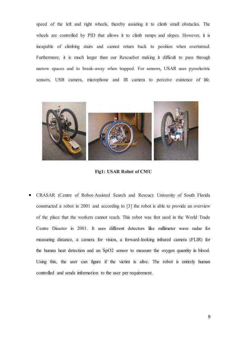
USAR (Urban Search and Rescue Robot): National Science Foundation funded Carnegie
Mellon University, Pittsburgh to explore the use of autonomous robots in rescue research.
[1] proposed necessary modifications in 2004 to the USAR built earlier by Carnegie
Mellon researchers which was capable to navigate difficult terrain but lacked sensors for
detection. The robot consists of two-bicycle wheels and uses differential drive by altering
9
speed of the left and right wheels, thereby assisting it to climb small obstacles. The
wheels are controlled by PID that allows it to climb ramps and slopes. However, it is
incapable of climbing stairs and cannot return back to position when overturned.
Furthermore, it is much larger than our Rescuebot making it difficult to pass through
narrow spaces and to break-away when trapped. For sensors, USAR uses pyroelectric
sensors, USB camera, microphone and IR camera to perceive existence of life.
Fig1: USAR Robot of CMU
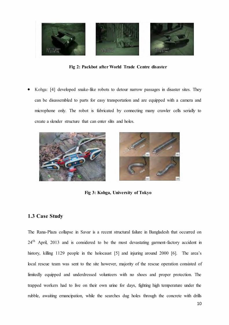
CRASAR (Centre of Robot-Assisted Search and Rescue): University of South Florida
constructed a robot in 2001 and according to [3] the robot is able to provide an overview
of the place that the workers cannot reach. This robot was first used in the World Trade
Centre Disaster in 2001. It uses different detectors like millimeter wave radar for
measuring distance, a camera for vision, a forward-looking infrared camera (FLIR) for
the human heat detection and an SpO2 sensor to measure the oxygen quantity in blood.
Using this, the user can figure if the victim is alive. The robot is entirely human
controlled and sends information to the user per requirement.
10
Fig 2: Packbot after World Trade Centre disaster
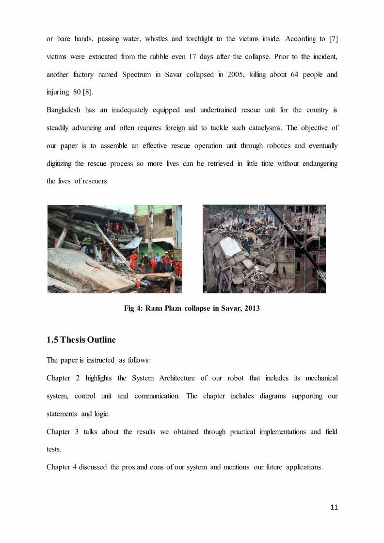
Kohga: [4] developed snake-like robots to detour narrow passages in disaster sites. They
can be disassembled to parts for easy transportation and are equipped with a camera and
microphone only. The robot is fabricated by connecting many crawler cells serially to
create a slender structure that can enter slits and holes.
Fig 3: Kohga, University of Tokyo
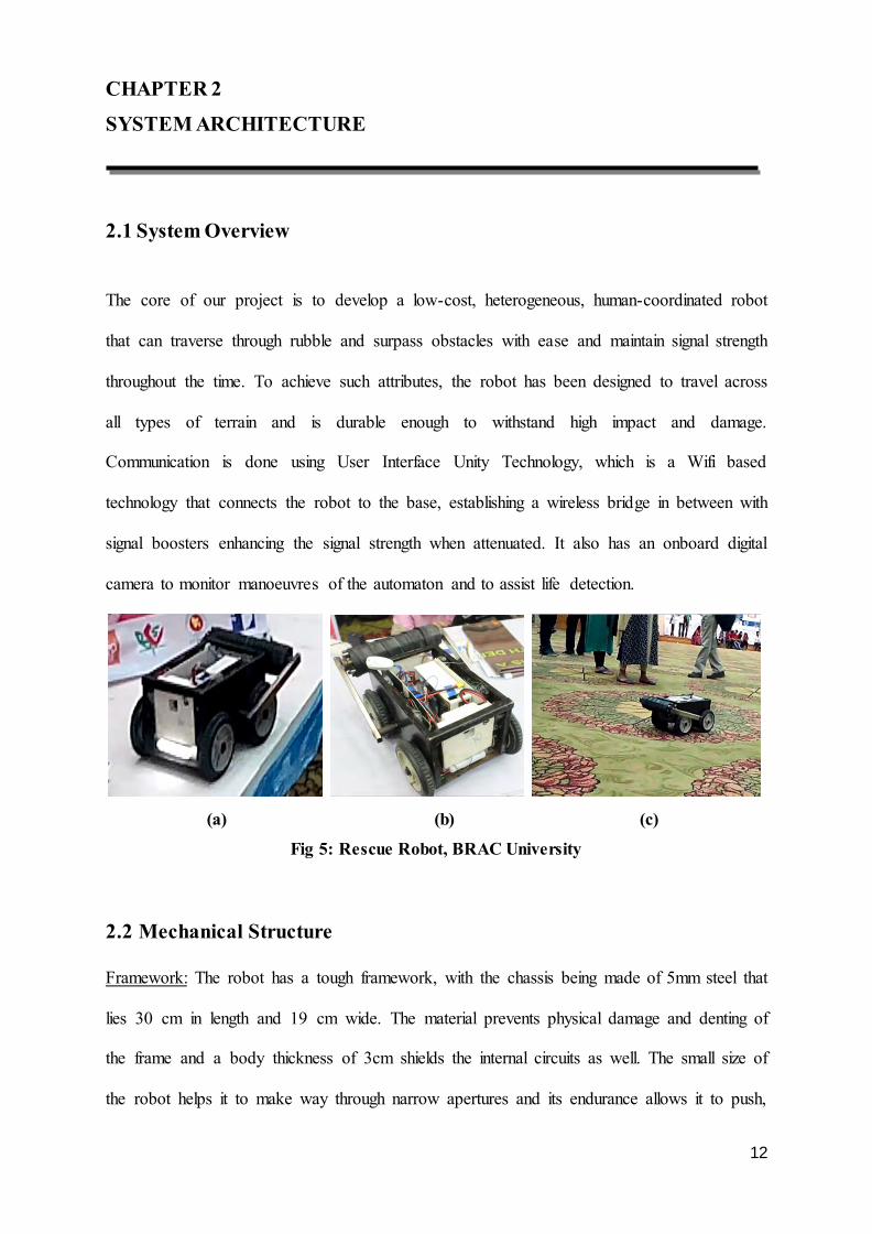
1.3 Case Study
The Rana-Plaza collapse in Savar is a recent structural failure in Bangladesh that occurred on
24th April, 2013 and is considered to be the most devastating garment-factory accident in
history, killing 1129 people in the holocaust [5] and injuring around 2000 [6]. The area’s
local rescue team was sent to the site however, majority of the rescue operation consisted of
limitedly equipped and underdressed volunteers with no shoes and proper protection. The
trapped workers had to live on their own urine for days, fighting high temperature under the
rubble, awaiting emancipation, while the searches dug holes through the concrete with drills
11
or bare hands, passing water, whistles and torchlight to the victims inside. According to [7]
victims were extricated from the rubble even 17 days after the collapse. Prior to the incident,
another factory named Spectrum in Savar collapsed in 2005, killing about 64 people and
injuring 80 [8].
Bangladesh has an inadequately equipped and undertrained rescue unit for the country is
steadily advancing and often requires foreign aid to tackle such cataclysms. The objective of
our paper is to assemble an effective rescue operation unit through robotics and eventually
digitizing the rescue process so more lives can be retrieved in little time without endangering
the lives of rescuers.
Fig 4: Rana Plaza collapse in Savar, 2013
1.5 Thesis Outline
The paper is instructed as follows:
Chapter 2 highlights the System Architecture of our robot that includes its mechanical
system, control unit and communication. The chapter includes diagrams supporting our
statements and logic.
Chapter 3 talks about the results we obtained through practical implementations and field
tests.
Chapter 4 discussed the pros and cons of our system and mentions our future applications.
12
CHAPTER 2
SYSTEM ARCHITECTURE
2.1 System Overview
The core of our project is to develop a low-cost, heterogeneous, human-coordinated robot
that can traverse through rubble and surpass obstacles with ease and maintain signal strength
throughout the time. To achieve such attributes, the robot has been designed to travel across
all types of terrain and is durable enough to withstand high impact and damage.
Communication is done using User Interface Unity Technology, which is a Wifi based
technology that connects the robot to the base, establishing a wireless bridge in between with
signal boosters enhancing the signal strength when attenuated. It also has an onboard digital
camera to monitor manoeuvres of the automaton and to assist life detection.
(a) (b) (c)
Fig 5: Rescue Robot, BRAC University
2.2 Mechanical Structure
Framework: The robot has a tough framework, with the chassis being made of 5mm steel that
lies 30 cm in length and 19 cm wide. The material prevents physical damage and denting of
the frame and a body thickness of 3cm shields the internal circuits as well. The small size of
the robot helps it to make way through narrow apertures and its endurance allows it to push,
13
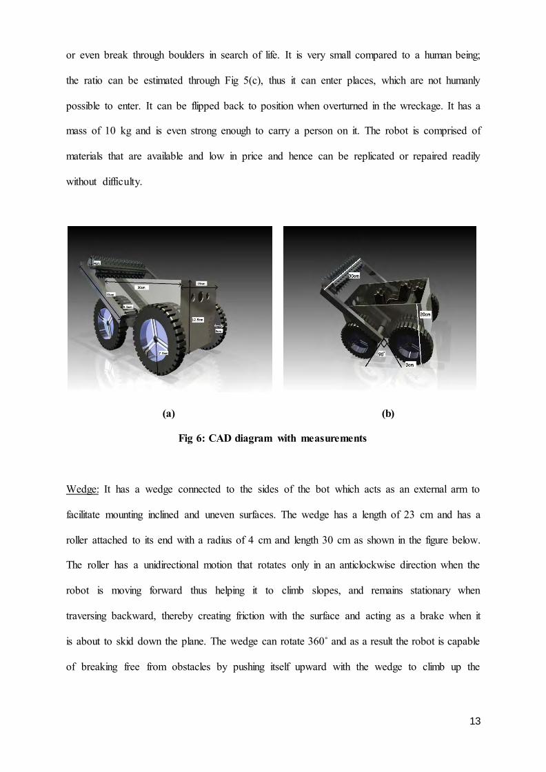
or even break through boulders in search of life. It is very small compared to a human being;
the ratio can be estimated through Fig 5(c), thus it can enter places, which are not humanly
possible to enter. It can be flipped back to position when overturned in the wreckage. It has a
mass of 10 kg and is even strong enough to carry a person on it. The robot is comprised of
materials that are available and low in price and hence can be replicated or repaired readily
without difficulty.
(a) (b)
Fig 6: CAD diagram with measurements
Wedge: It has a wedge connected to the sides of the bot which acts as an external arm to
facilitate mounting inclined and uneven surfaces. The wedge has a length of 23 cm and has a
roller attached to its end with a radius of 4 cm and length 30 cm as shown in the figure below.
The roller has a unidirectional motion that rotates only in an anticlockwise direction when the
robot is moving forward thus helping it to climb slopes, and remains stationary when
traversing backward, thereby creating friction with the surface and acting as a brake when it
is about to skid down the plane. The wedge can rotate 360˚ and as a result the robot is capable
of breaking free from obstacles by pushing itself upward with the wedge to climb up the
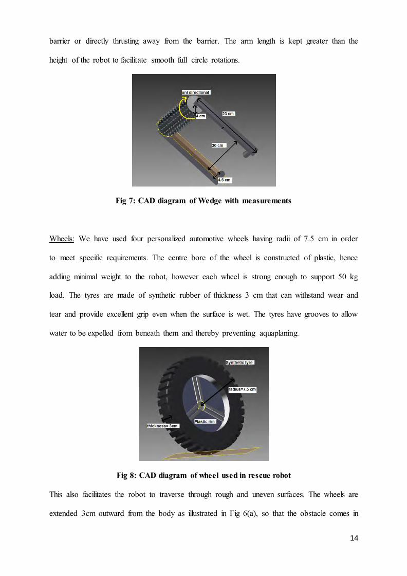
14
barrier or directly thrusting away from the barrier. The arm length is kept greater than the
height of the robot to facilitate smooth full circle rotations.
Fig 7: CAD diagram of Wedge with measurements
Wheels: We have used four personalized automotive wheels having radii of 7.5 cm in order
to meet specific requirements. The centre bore of the wheel is constructed of plastic, hence
adding minimal weight to the robot, however each wheel is strong enough to support 50 kg
load. The tyres are made of synthetic rubber of thickness 3 cm that can withstand wear and
tear and provide excellent grip even when the surface is wet. The tyres have grooves to allow
water to be expelled from beneath them and thereby preventing aquaplaning.
Fig 8: CAD diagram of wheel used in rescue robot
This also facilitates the robot to traverse through rough and uneven surfaces. The wheels are
extended 3cm outward from the body as illustrated in Fig 6(a), so that the obstacle comes in
15
contact with the wheels first then body thereby preventing damage and thereby achieving
greater control over the droid in breaking free. The spacing between the two pairs of wheels
is kept at 90˚ as illustrated in Fig 6 (b) and a large ride height or ground clearance (i.e. the
space between the base of the chassis and base of the tyres) is maintained. This ensures that
the centre of gravity of the robot is higher, hence making it easier for it to climb stairs.
Clearance usually hinders automobile handling, but our robot remains unaffected as it can be
flipped back to position. The wheels are connected to the shaft of the motor with nuts and
bolts, thus enabling quick and ease replacement of tyres when necessary.
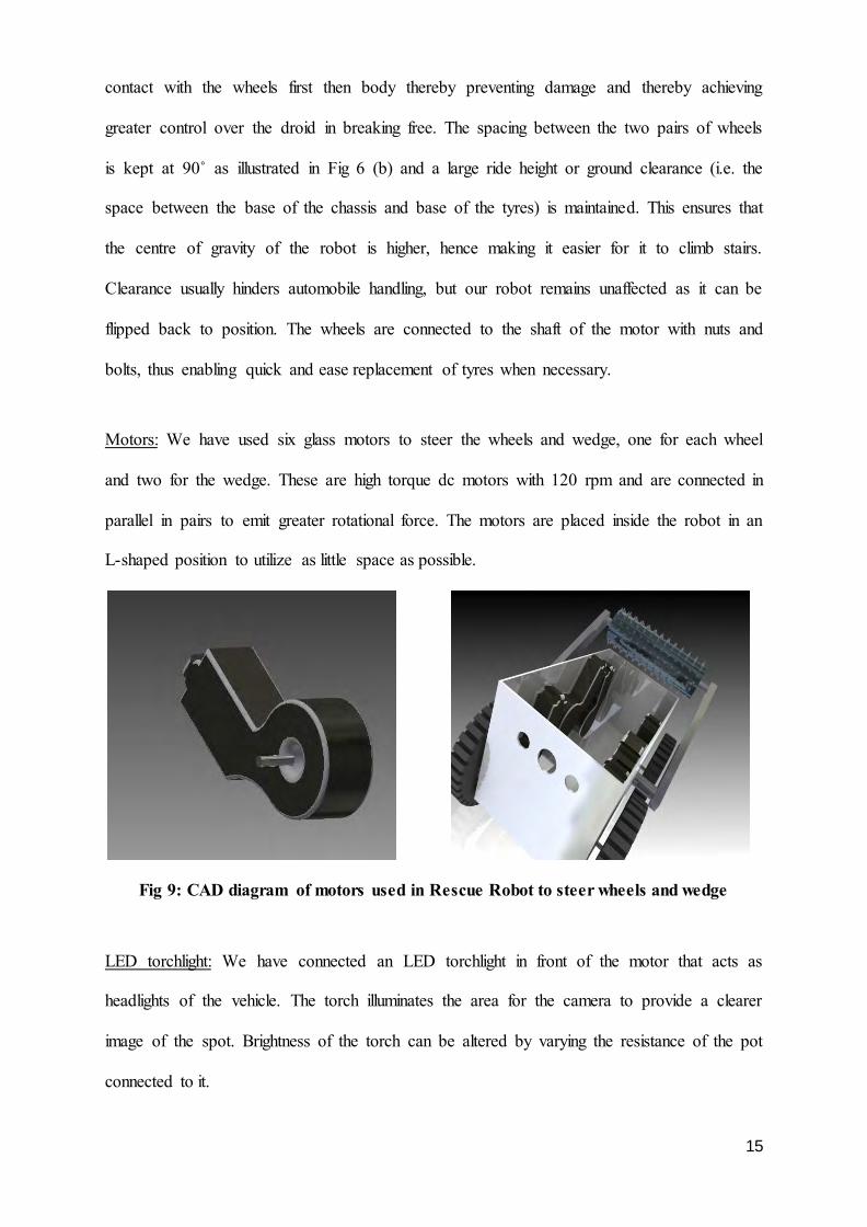
Motors: We have used six glass motors to steer the wheels and wedge, one for each wheel
and two for the wedge. These are high torque dc motors with 120 rpm and are connected in
parallel in pairs to emit greater rotational force. The motors are placed inside the robot in an
L-shaped position to utilize as little space as possible.
Fig 9: CAD diagram of motors used in Rescue Robot to steer wheels and wedge
LED torchlight: We have connected an LED torchlight in front of the motor that acts as
headlights of the vehicle. The torch illuminates the area for the camera to provide a clearer
image of the spot. Brightness of the torch can be altered by varying the resistance of the pot
connected to it.
16
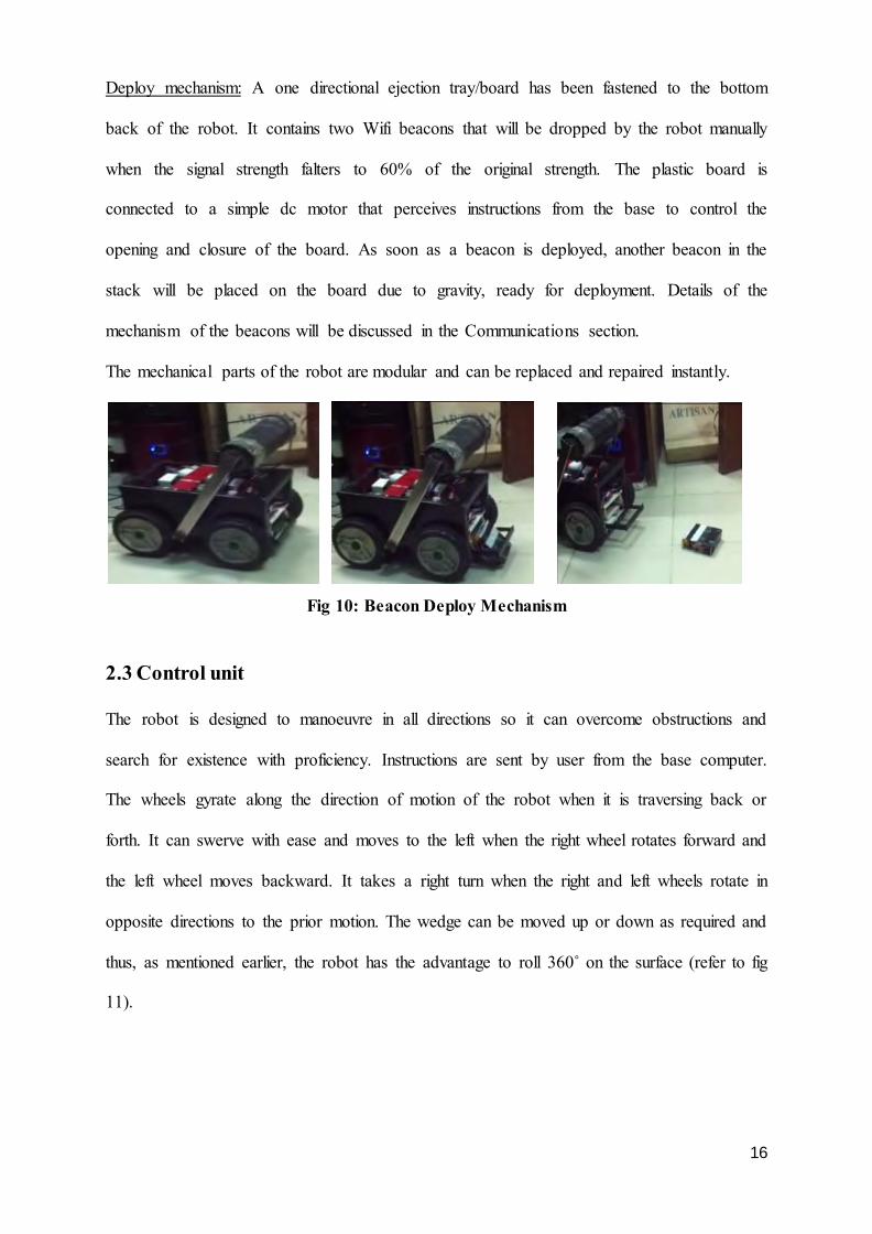
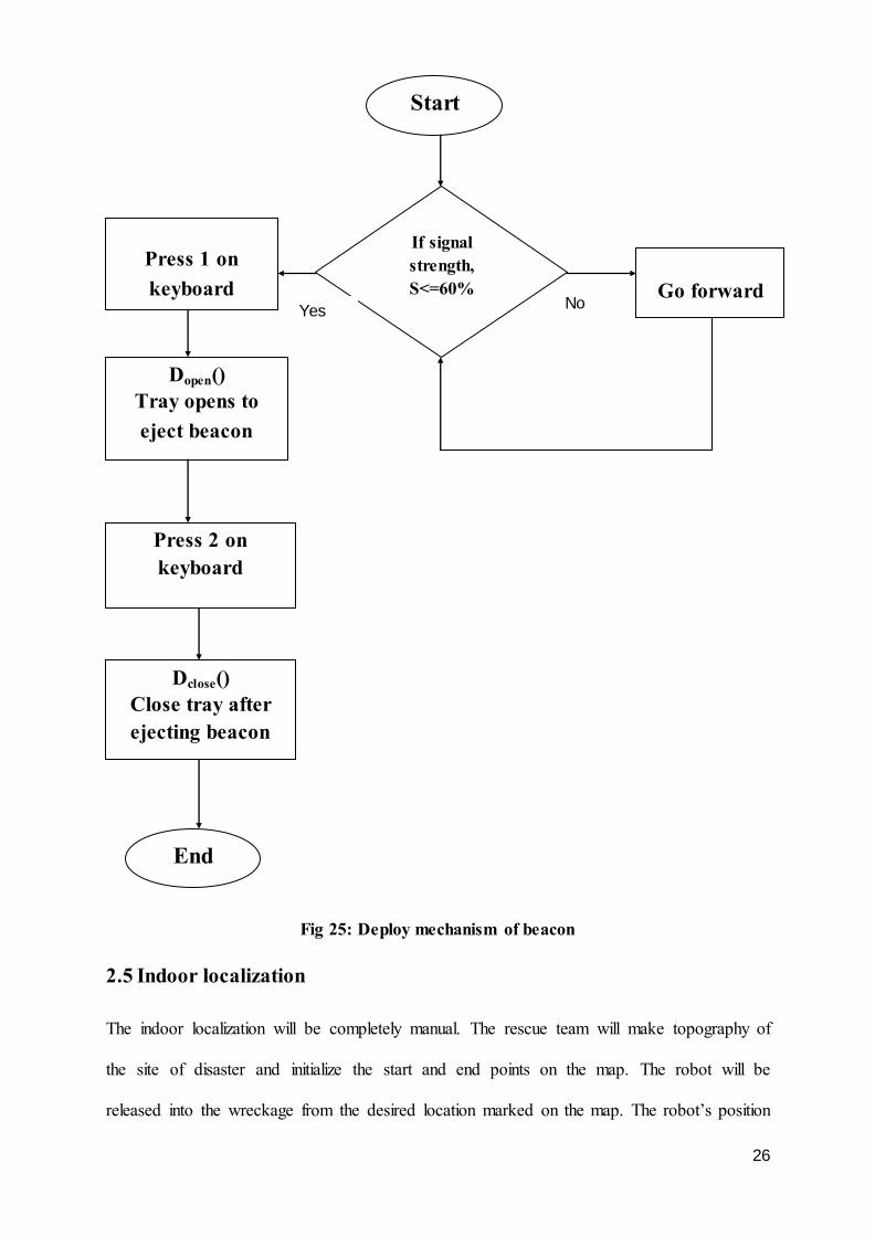
Deploy mechanism: A one directional ejection tray/board has been fastened to the bottom
back of the robot. It contains two Wifi beacons that will be dropped by the robot manually
when the signal strength falters to 60% of the original strength. The plastic board is
connected to a simple dc motor that perceives instructions from the base to control the
opening and closure of the board. As soon as a beacon is deployed, another beacon in the
stack will be placed on the board due to gravity, ready for deployment. Details of the
mechanism of the beacons will be discussed in the Communications section.
The mechanical parts of the robot are modular and can be replaced and repaired instantly.
Fig 10: Beacon Deploy Mechanism
2.3 Control unit
The robot is designed to manoeuvre in all directions so it can overcome obstructions and
search for existence with proficiency. Instructions are sent by user from the base computer.
The wheels gyrate along the direction of motion of the robot when it is traversing back or
forth. It can swerve with ease and moves to the left when the right wheel rotates forward and
the left wheel moves backward. It takes a right turn when the right and left wheels rotate in
opposite directions to the prior motion. The wedge can be moved up or down as required and
thus, as mentioned earlier, the robot has the advantage to roll 360˚ on the surface (refer to fig
11).
17
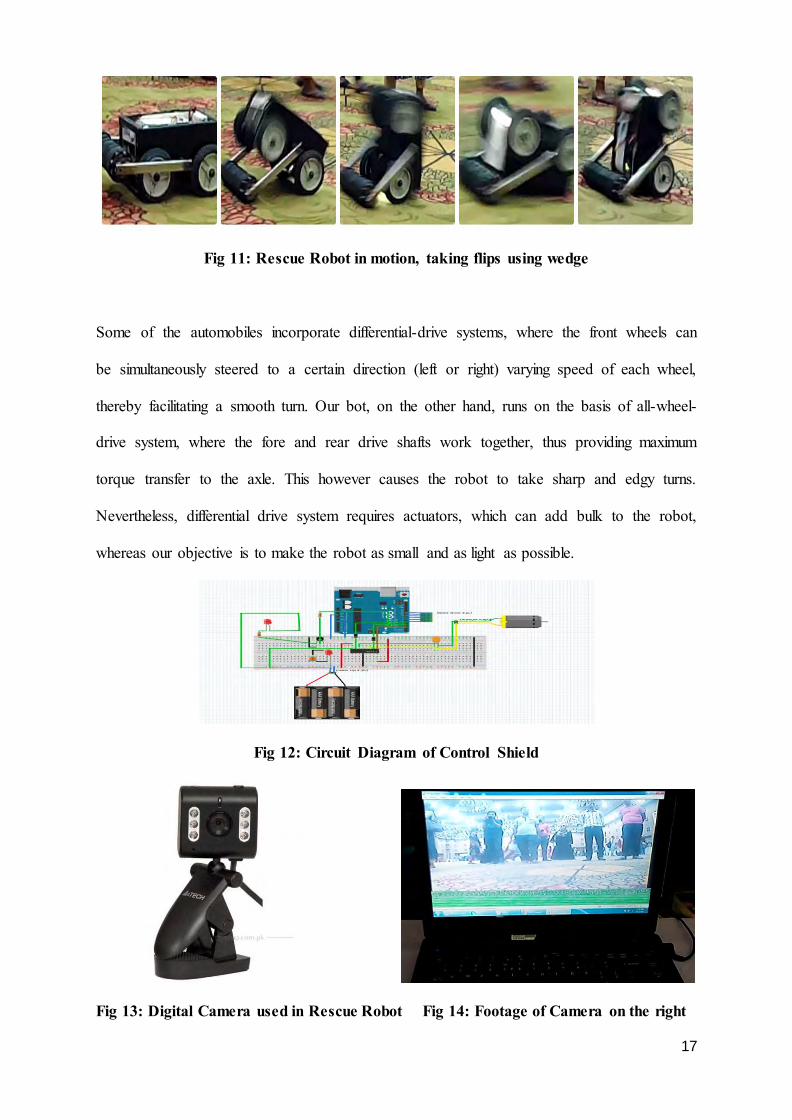
Fig 11: Rescue Robot in motion, taking flips using wedge
Some of the automobiles incorporate differential-drive systems, where the front wheels can
be simultaneously steered to a certain direction (left or right) varying speed of each wheel,
thereby facilitating a smooth turn. Our bot, on the other hand, runs on the basis of all-wheel-
drive system, where the fore and rear drive shafts work together, thus providing maximum
torque transfer to the axle. This however causes the robot to take sharp and edgy turns.
Nevertheless, differential drive system requires actuators, which can add bulk to the robot,
whereas our objective is to make the robot as small and as light as possible.
Fig 12: Circuit Diagram of Control Shield
Fig 13: Digital Camera used in Rescue Robot Fig 14: Footage of Camera on the right
18
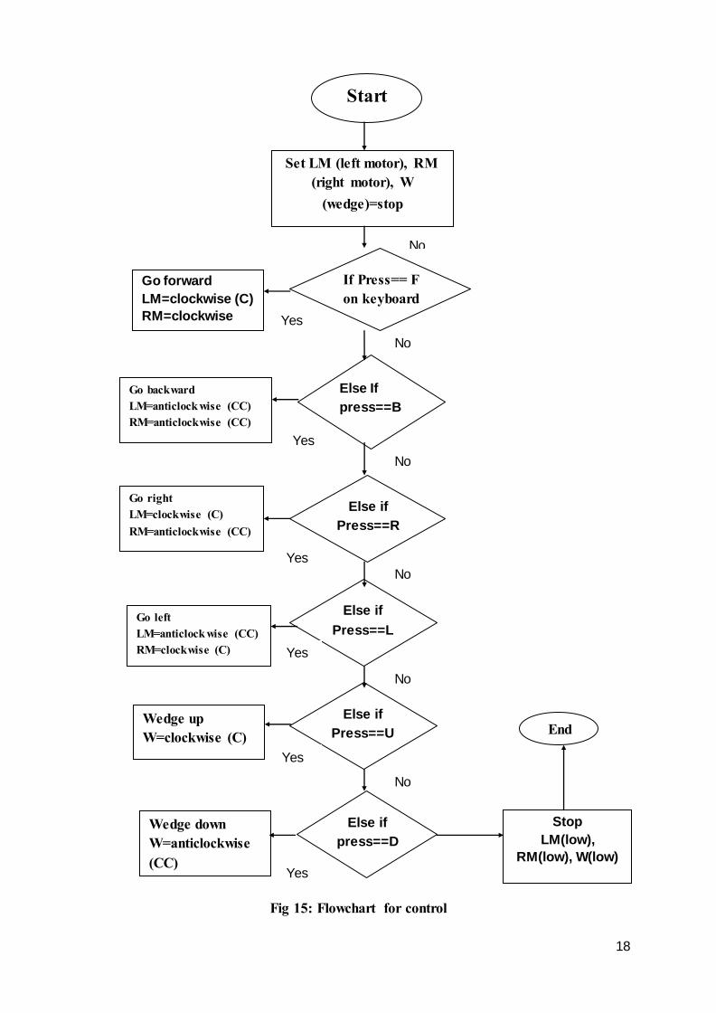
Fig 15: Flowchart for control
Start
Set LM (left motor), RM (right motor), W
(wedge)=stop
If Press== F on keyboard
Go forward
LM=clockwise (C)
RM=clockwise
(C)
Else If
press==B
Else if
Press==R
Go backward LM=anticlock wise (CC) RM=anticlockwise (CC)
Go right LM=clockwise (C) RM=anticlockwise (CC)
Go left LM=anticlock wise (CC) RM=clockwise (C)
Else if
Press==L
Else if
Press==U
Else if
press==D
Wedge up W=clockwise (C)
Wedge down W=anticlockwise (CC)
Stop
LM(low),
RM(low), W(low)
End
No
No
No
No
No
No
Yes
Yes
Yes
es
Yes
Yes
Yes
19
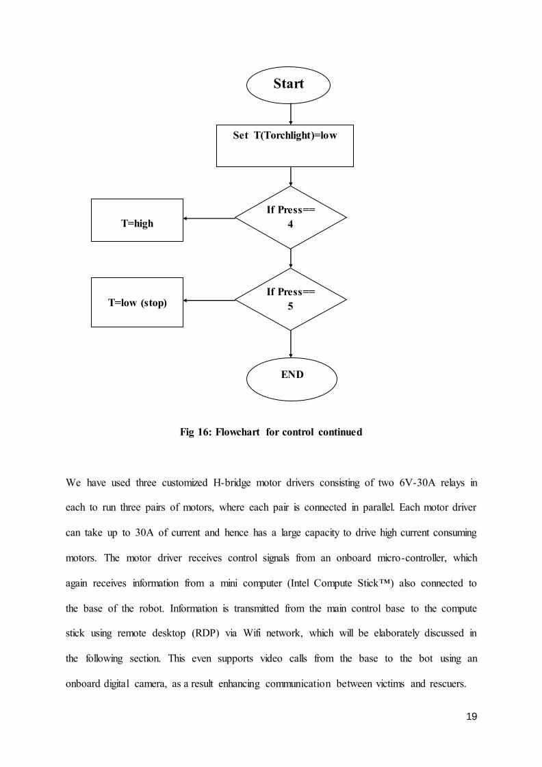
Fig 16: Flowchart for control continued
We have used three customized H-bridge motor drivers consisting of two 6V-30A relays in
each to run three pairs of motors, where each pair is connected in parallel. Each motor driver
can take up to 30A of current and hence has a large capacity to drive high current consuming
motors. The motor driver receives control signals from an onboard micro-controller, which
again receives information from a mini computer (Intel Compute Stick™) also connected to
the base of the robot. Information is transmitted from the main control base to the compute
stick using remote desktop (RDP) via Wifi network, which will be elaborately discussed in
the following section. This even supports video calls from the base to the bot using an
onboard digital camera, as a result enhancing communication between victims and rescuers.
Start
Set T(Torchlight)=low
If Press== 5
T=low (stop)
T=high
If Press== 4
END
20
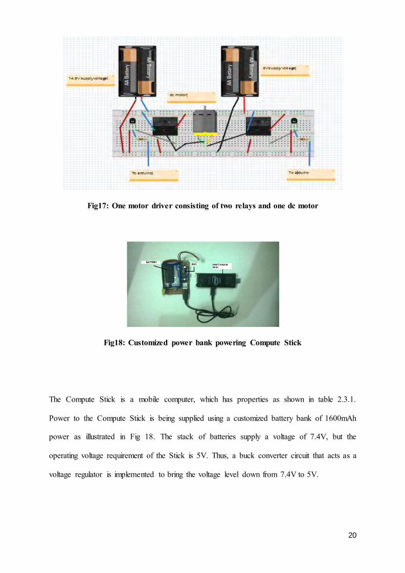
Fig17: One motor driver consisting of two relays and one dc motor
Fig18: Customized power bank powering Compute Stick
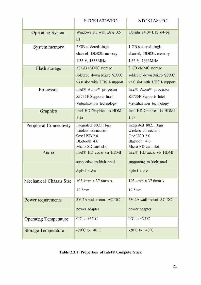
The Compute Stick is a mobile computer, which has properties as shown in table 2.3.1.
Power to the Compute Stick is being supplied using a customized battery bank of 1600mAh
power as illustrated in Fig 18. The stack of batteries supply a voltage of 7.4V, but the
operating voltage requirement of the Stick is 5V. Thus, a buck converter circuit that acts as a
voltage regulator is implemented to bring the voltage level down from 7.4V to 5V.
21
STCK1A32WFC STCK1A8LFC
Operating System Windows 8.1 with Bing 32-
bit
Ubuntu 14.04 LTS 64-bit
System memory 2 GB soldered single
channel, DDR3L memory
1.35 V, 1333MHz
1 GB soldered single
channel, DDR3L memory
1.35 V, 1333MHz
Flash storage 32 GB eMMC storage
soldered down Micro SDXC
v3.0 slot with UHS I-support
8 GB eMMC storage
soldered down Micro SDXC
v3.0 slot with UHS I-support
Processor Intel® Atom™ processor
Z3735F Supports Intel
Virtualization technology
Intel® Atom™ processor
Z3735F Supports Intel
Virtualization technology
Graphics Intel HD Graphics 1x HDMI
1.4a
Intel HD Graphics 1x HDMI
1.4a
Peripheral Connectivity Integrated 802.11bgn wireless connection One USB 2.0 Bluetooth 4.0 Micro SD card slot
Integrated 802.11bgn wireless connection One USB 2.0 Bluetooth 4.0 Micro SD card slot
Audio Intel® HD audio via HDMI
supporting multichannel
digital audio
Intel® HD audio via HDMI
supporting multichannel
digital audio
Mechanical Chassis Size 103.4mm x 37.6mm x
12.5mm
103.4mm x 37.6mm x
12.5mm
Power requirements 5V 2A wall mount AC DC
power adapter
5V 2A wall mount AC DC
power adapter
Operating Temperature 0˚C to +35˚C 0˚C to +35˚C
Storage Temperature -20˚C to +40˚C -20˚C to +40˚C
Table 2.3.1: Properties of Intel® Compute Stick
22
2.4 Communication
Although limited, there are multiple ways to communicate in an indoor environment. Initially
we chose to communicate using Radio frequency that refers to an alternating current, which
when fed into an antenna generates an electromagnetic wave that is suitable for wireless
broadcasting or communication. It ranges from 3 KHz to frequencies roughly as high as
3GHz and it is the high frequency that immunes it from noise distortion, allows efficient
propagation and diminishes the size of antenna, which is usually 1/4 th the wavelength of the
signal. And as we all know, wavelength of a signal is inversely proportional to the frequency
of the signal that is, increasing frequency decreases wavelength and vice versa.
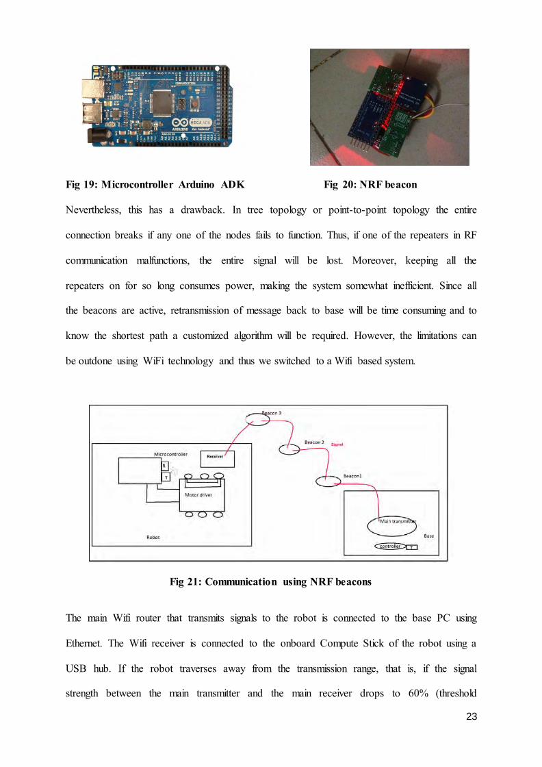
We have employed Nordic radio frequency (NRF 24101) transmitter to send information
signals from the central control unit (base) to the rescuebot, which has an NRF receiver
embedded in it. The robot is manipulated using a wireless controller that transmits
instructions using RF from the base to the onboard microcontroller that is connected to the
motor driver of the robot. The microcontroller also has a transmitter to send feedbacks and
readings to the base from the bot. However, indoor localization and maintaining signal
strength in a collapsed building can be critical, especially when the parameters of the
environment are unknown. The connection of the bot with the base is likely to disrupt when it
enters deeper into the wreckage due to noise and physical obstructions. Thus, we have
implanted signal boosters consisting of NRF beacons to the system that will extend the
network coverage in a given area. We will instruct the robot to drop a beacon when the signal
strength falters below a threshold. The main transmitter at the base will then transmit signal
to the beacon instead, which will relay the information to the robot thereby covering twice the
distance it could have covered without the beacon. To travel greater distance, more of such
beacons can be dropped thus creating a point-to-point network disseminating the signal to the
destination without loss (refer to fig 21).
23
Fig 19: Microcontroller Arduino ADK Fig 20: NRF beacon
Nevertheless, this has a drawback. In tree topology or point-to-point topology the entire
connection breaks if any one of the nodes fails to function. Thus, if one of the repeaters in RF
communication malfunctions, the entire signal will be lost. Moreover, keeping all the
repeaters on for so long consumes power, making the system somewhat inefficient. Since all
the beacons are active, retransmission of message back to base will be time consuming and to
know the shortest path a customized algorithm will be required. However, the limitations can
be outdone using WiFi technology and thus we switched to a Wifi based system.
Fig 21: Communication using NRF beacons
The main Wifi router that transmits signals to the robot is connected to the base PC using
Ethernet. The Wifi receiver is connected to the onboard Compute Stick of the robot using a
USB hub. If the robot traverses away from the transmission range, that is, if the signal
strength between the main transmitter and the main receiver drops to 60% (threshold
24
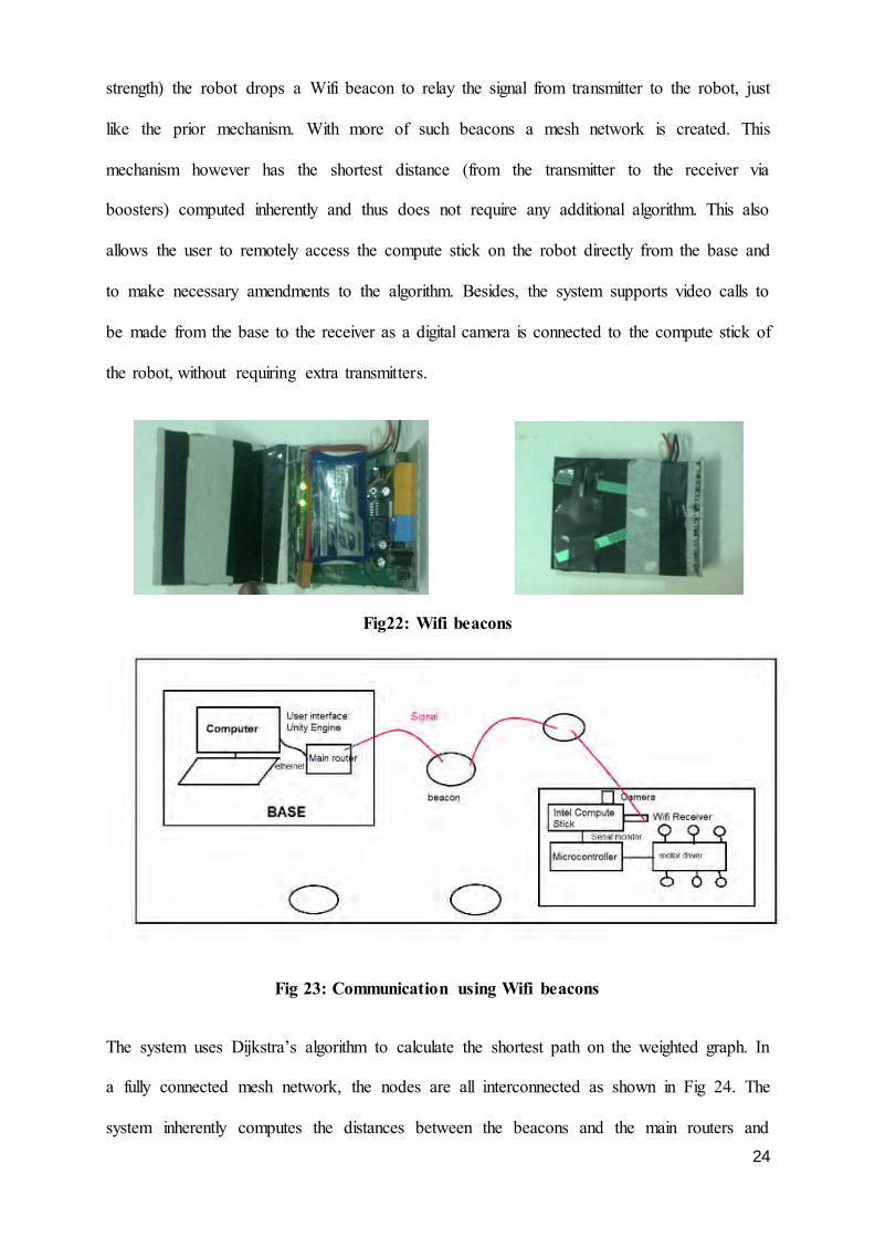
strength) the robot drops a Wifi beacon to relay the signal from transmitter to the robot, just
like the prior mechanism. With more of such beacons a mesh network is created. This
mechanism however has the shortest distance (from the transmitter to the receiver via
boosters) computed inherently and thus does not require any additional algorithm. This also
allows the user to remotely access the compute stick on the robot directly from the base and
to make necessary amendments to the algorithm. Besides, the system supports video calls to
be made from the base to the receiver as a digital camera is connected to the compute stick of
the robot, without requiring extra transmitters.
Fig22: Wifi beacons
Fig 23: Communication using Wifi beacons
The system uses Dijkstra’s algorithm to calculate the shortest path on the weighted graph. In
a fully connected mesh network, the nodes are all interconnected as shown in Fig 24. The
system inherently computes the distances between the beacons and the main routers and
25
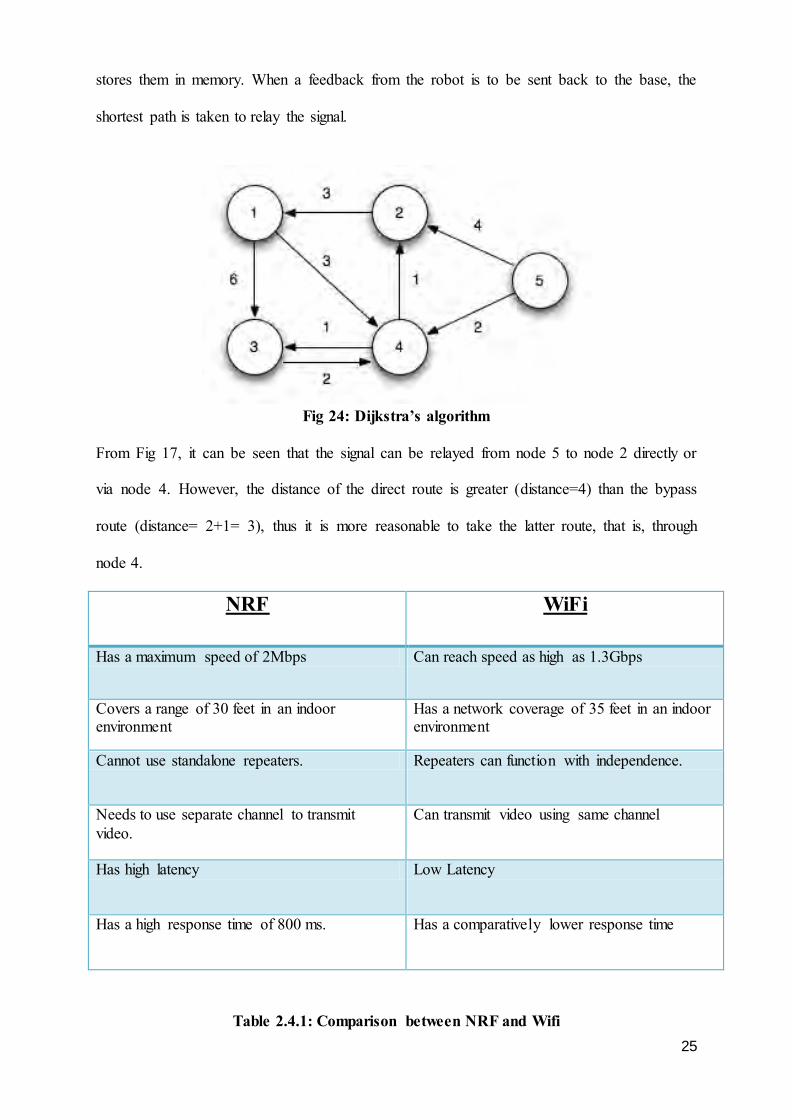
stores them in memory. When a feedback from the robot is to be sent back to the base, the
shortest path is taken to relay the signal.
Fig 24: Dijkstra’s algorithm
From Fig 17, it can be seen that the signal can be relayed from node 5 to node 2 directly or
via node 4. However, the distance of the direct route is greater (distance=4) than the bypass
route (distance= 2+1= 3), thus it is more reasonable to take the latter route, that is, through
node 4.
NRF WiFi
Has a maximum speed of 2Mbps Can reach speed as high as 1.3Gbps
Covers a range of 30 feet in an indoor environment
Has a network coverage of 35 feet in an indoor environment
Cannot use standalone repeaters. Repeaters can function with independence.
Needs to use separate channel to transmit video.
Can transmit video using same channel
Has high latency Low Latency
Has a high response time of 800 ms. Has a comparatively lower response time
Table 2.4.1: Comparison between NRF and Wifi
26
Fig 25: Deploy mechanism of beacon
2.5 Indoor localization The indoor localization will be completely manual. The rescue team will make topography of
the site of disaster and initialize the start and end points on the map. The robot will be
released into the wreckage from the desired location marked on the map. The robot’s position
Start
If signal strength, S<=60%
Dopen() Tray opens to eject beacon
Press 2 on keyboard
Press 1 on keyboard
Go forward
Dclose() Close tray after ejecting beacon
End
Yes No
27
and movements will be tracked using the onboard digital camera that will broadcast
streaming videos of the interior using Wifi to the base computer and thus enabling the user to
trace the course or path taken by the bot on the map. Whenever a victim is sighted, it will
release a buzzer or blinker in the locale to indicate existence of life and the user will mark the
location on the map accordingly so that a squad can be sent to the precise location to dig a
hole through the rubble and rescue the victim. Using this scheme the robot can also be
manoeuvred out of the rubble when necessary.
2.6 Power
For the motors and wedges we have used 4 cell 5500mA-power, 14.8V battery.
Power calculation for motors driving the wheels in no-load condition:
Steady current through each motor, I= 1.74 A
Voltage across each motor, V= 14.8 V
Power required for one rotation of each motor= VI= 1.74 x 14.8= 25.75 W
Power required for 4 motors= 4 x 25.75= 103.01W
Power calculation for motors with load:
Steady current through each motor, I= 2.18A
Voltage across each motor, V= 14.8 V
Power required for one rotation of each motor= VI= 2.18 x 14.8= 32.2 W
Power required for 4 motors= 4 x 32.2= 129 W
*Each of the four motors driving the wheels will approximately carry a load of 2.5 kg.
Power required by the supplementary motors driving the wedge
= 2.18 x 14.8 x 2= 64.53 W
The onboard Compute Stick uses a lithium polymer battery of 1600mAH power and 7.5V
that can last up to 5 hours approximately.
28
CHAPTER 3
RESULT
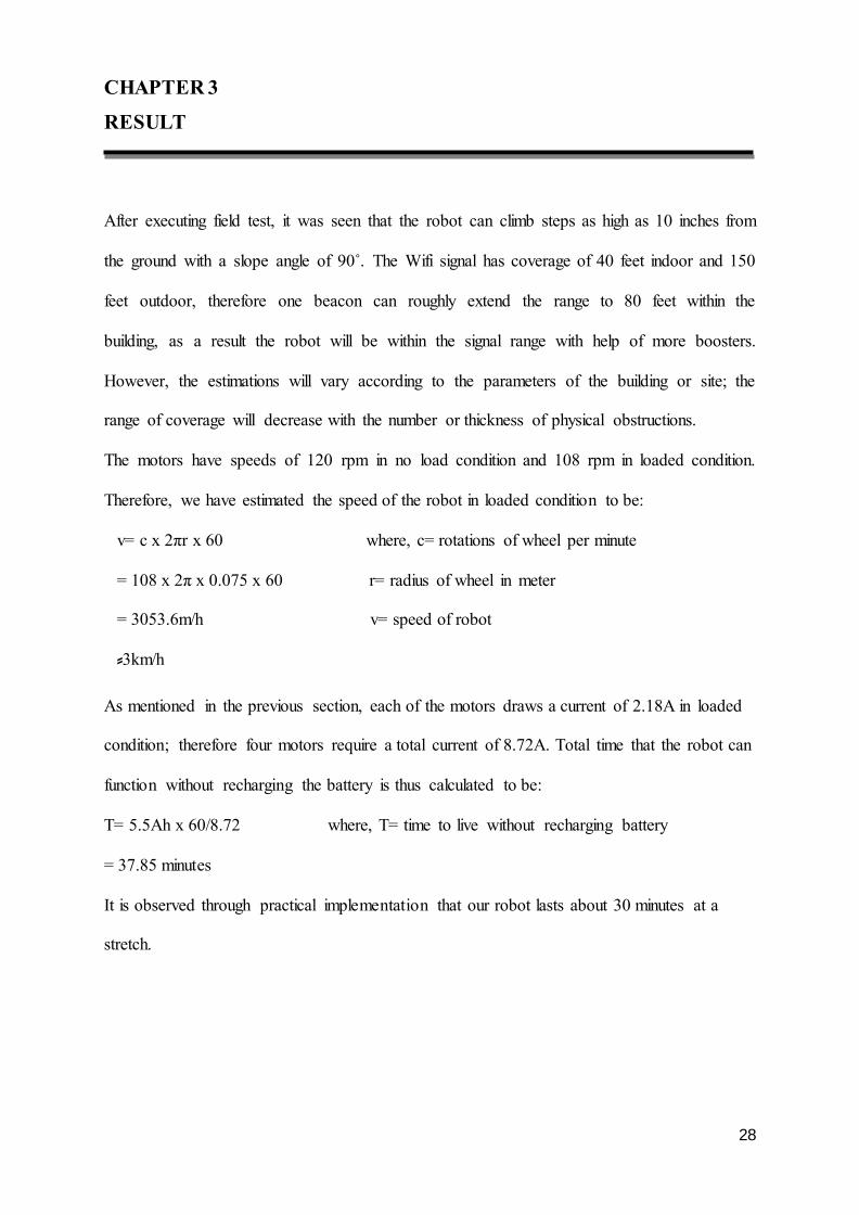
After executing field test, it was seen that the robot can climb steps as high as 10 inches from
the ground with a slope angle of 90˚. The Wifi signal has coverage of 40 feet indoor and 150
feet outdoor, therefore one beacon can roughly extend the range to 80 feet within the
building, as a result the robot will be within the signal range with help of more boosters.
However, the estimations will vary according to the parameters of the building or site; the
range of coverage will decrease with the number or thickness of physical obstructions.
The motors have speeds of 120 rpm in no load condition and 108 rpm in loaded condition.
Therefore, we have estimated the speed of the robot in loaded condition to be:
v= c x 2πr x 60 where, c= rotations of wheel per minute
= 108 x 2π x 0.075 x 60 r= radius of wheel in meter
= 3053.6m/h v= speed of robot
⸗3km/h As mentioned in the previous section, each of the motors draws a current of 2.18A in loaded
condition; therefore four motors require a total current of 8.72A. Total time that the robot can
function without recharging the battery is thus calculated to be:
T= 5.5Ah x 60/8.72 where, T= time to live without recharging battery
= 37.85 minutes
It is observed through practical implementation that our robot lasts about 30 minutes at a
stretch.
29
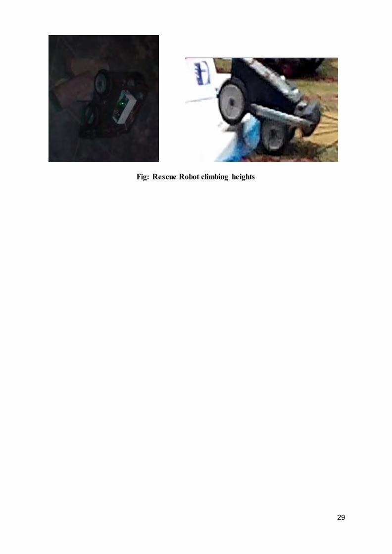
Fig: Rescue Robot climbing heights
30
CHAPTER 4
DISCUSSION
4.1 Features and limitations
Most of the robots that have been built for rescue purpose so far can detect life with accuracy
using different sensors. But a very few have concentrated on the size and durability of the
robot. Our main purpose was to modify their ideas to come up with a robot that is small
enough to enter narrow gaps but strong enough to withstand impact. Thus, our robot is of
optimum size and strength. Secondly, most of the robots built earlier are not all-terrain, that
is, they cannot travel in all types of surfaces. So, we focused on making our robot all-terrain,
so it can traverse on both rough and slippery surfaces as well as can climb heights and stairs.
Lastly and most importantly, our robot maintains signal strength at all times using connecting
beacons or boosters. Additional features include the use of an adjacent LED torch light and a
digital camera to monitor its movements and detect life.
However, it cannot perceive the existence of life with accuracy due to lack of important
sensors. A digital camera itself is not reliable enough to predict existence of life as the
victims will be covered in debris or even entombed in void. It may mistake a deceased for a
living person hence resulting in unnecessary time consumption retrieving dead bodies instead
of victims striving for emancipation. The robot is neither fireproof nor waterproof and as it is
not autonomous it cannot find its way back out of the maze on its own. We need to keep track
of the robot manually, thereby making indoor positioning slightly difficult.
31
4.2 Future Implementation
We look forward to incorporating additional features to our project in the near feature. We
wish to include more sensors such as carbon dioxide and infra red sensors to enhance life
detection. Carbon dioxide sensors trigger a buzzer as the CO2 level in its vicinity reaches a
set threshold value to indicate the presence of a human being nearby as humans and animals
exhale carbon dioxide as part of respiration process. Nevertheless, according to [9], response
time of CO2 sensors is low and the robot has to be very near to the victim to obtain useful
data. To acquire more accurate result, we wish to implement IR camera, which is very
commonly used to distinguish between a living and a non-living object as it captures images
of heat emitting objects. Secondly, we hope to make our robot autonomous by implementing
artificial intelligence so it can deploy beacons autonomously when the signal strength abates
and responds by dropping blinkers or buzzers automatically when presence of life is detected.
It should be able to autonomously navigate in indoor environments using Wifi sensory data,
thus assisting localization. If all the necessary amendments are made, we look forward to
going into mass production and practically implementing our project in disaster sites, starting
with Bangladesh and gradually in other countries if successful.
32
REFERENCE
[1] Burion, Steve, Charles Baur, and Terry Fong. "Human Detection for Robotic Urban
Search and Rescue ." Diploma Work, INSTITUT DE PRODUCTION ROBOTIQUE
(IPR), Carnegie Mellon, Pittsburgh, 2004, 17-32.
[2] Hossain, Moazzem, ed. "Bangladesh 5th most disaster-prone country." The
Financial Express (International Publications Limited) 20, no. 157 (October 2012): 1.
[3] Casper, J. "Human-Robot Interactions during the Robot-Assisted Urban Search And
Rescue Respone at The World Trade Centre." MS Thesis, Computer Science and
Engineering, USF, South Florida, 2002.
[4] Burion, Steve, Charles Baur, and Terry Fong. "Human Detection for Robotic Urban
Search and Rescue ." Diploma Work, INSTITUT DE PRODUCTION ROBOTIQUE
(IPR), Carnegie Mellon, Pittsburgh, 2004, 6.
[5] Butler, Sarah. "Bangladeshi factory deaths spark action among high-street clothing
chains." The Guardian, June 23, 2013.
[6] Alam, Julhas, and Farid Hossain. "Yahoo! News." news.yahoo.com. May 13, 2013.
http://news.yahoo.com/bangladesh-collapse-search-over-death-toll-1-127-
122554495.html?soc_src=copy (accessed August 17, 2015).
[7] Manik, Julfikar Ali, and Jim Yardley. "17 Days in Darkness, a Cry of ‘Save Me,’ and
Joy." The New York Times, May 10, 2013, New York Edition ed.: A1.
[8] "Spectrum collapse: eight years on and still little action on safety." Clean Clothes
Campaign. April 11, 2013. http://www.cleanclothes.org/news/2013/04/11/spectrum-
collapse-eight-years-on-and-still-little-action-on-safety (accessed August 2015).
[9] Burion, Steve, Charles Baur, and Terry Fong. "Human Detection for Robotic Urban
Search and Rescue ." Diploma Work, INSTITUT DE PRODUCTION ROBOTIQUE
(IPR), Carnegie Mellon, Pittsburgh, 2004, 11-12.