Embed Size (px)
Citation preview

DSH 700/DSH 900
*288292*
288292
Hilti CorporationLI-9494 SchaanTel.: +423 / 234 21 11Fax: +423 / 234 29 65www.hilti.com
Hilti = registered trademark of Hilti Corp., Schaan W 3503 1110 00-Pos. 3 1 Printed in Italy © 2010Right of technical and programme changes reserved S. E. & O.
288292 / F
Operating instructions en
Mode d’emploi fr
Manual de instrucciones es
1/3
1/3
1/3
15
1
3/8
6
5
2/6
4/7
16
17
15
4
5
0.5mm2/8
14
6
7
5
1/12
2
10
8
4
4
3
12
2
3
13
00_Cover_DSH700_900_P3.qxd:00_Cover_DSH700_900_P3 15.11.2010 16:26 Uhr Seite 1

19
2
"≠
+# +] +[
"Ç
+|
5+}
+≠ 7 6
+±
4 +{ "#
+“ "“
"[
+Ç
3 "±
8
1 2
1/8
1/8
4
2/7/9
3
3
1/1514
2/45/13
46
3/10
87
9
11
4
1
2
5
15
7
3
2/4
3
6
6
6
2
56
3
4
8
9/10
8
7
3/4
3/4
3/4
3/4
11
1/5
1/5
2
10
8 9
This Product is ListedCe produit est homologuéProducto homologado porEste produto está registrado
R
00_Cover_DSH700_900_P3.qxd:00_Cover_DSH700_900_P3 15.11.2010 16:26 Uhr Seite 5
ORIGINAL OPERATING INSTRUCTIONS
DSH 700/ DSH 900 cut-off sawIt is essential that the operating instruc-tions are read before the machine is oper-ated for the first time.
Always keep these operating instructionstogether with the machine.
Ensure that the operating instructions arewith the machine when it is given to otherpersons.
Contents Page1. General information 22. Description 33. Accessories 44. Technical data 55. Safety instructions 66. Before use 97. Operation 138. Care and maintenance 149. Troubleshooting 18
10. Disposal 2011. Federal emission control warranty
statement 2012. Manufacturer’s warranty 21
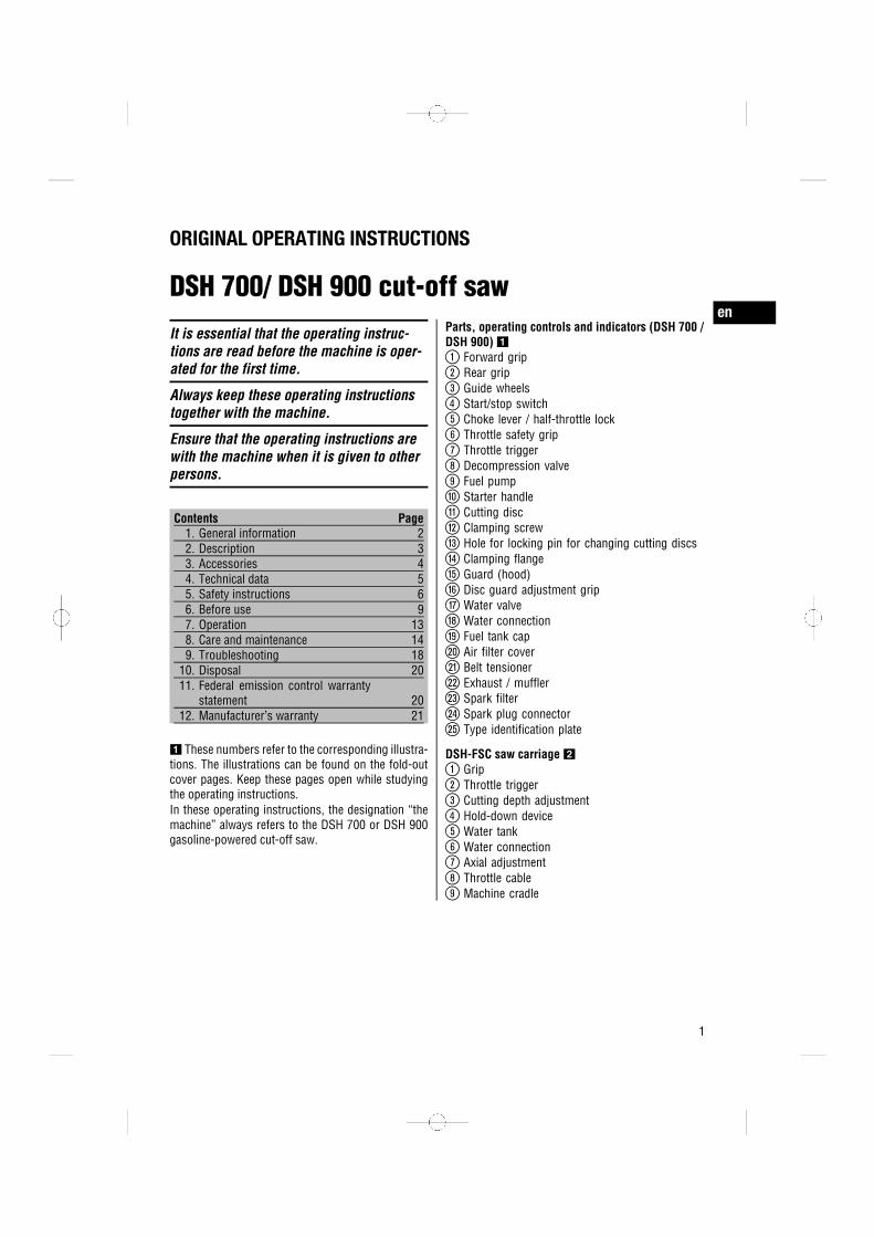
1 These numbers refer to the corresponding illustra-tions. The illustrations can be found on the fold-outcover pages. Keep these pages open while studyingthe operating instructions.In these operating instructions, the designation “themachine” always refers to the DSH 700 or DSH 900gasoline-powered cut-off saw.
Parts, operating controls and indicators (DSH 700 /DSH 900) 1
@Forward grip
;Rear grip
=Guide wheels
%Start/stop switch
&Choke lever / half-throttle lock
(Throttle safety grip
)Throttle trigger
+Decompression valve
§Fuel pump
/Starter handle
:Cutting disc
·Clamping screw
$Hole for locking pin for changing cutting discs
£Clamping flange
|Guard (hood)
¡Disc guard adjustment grip
QWater valve
WWater connection
EFuel tank cap
RAir filter cover
TBelt tensioner
ZExhaust / muffler
USpark filter
ISpark plug connector
OType identification plate
DSH-FSC saw carriage 2
@Grip
;Throttle trigger
=Cutting depth adjustment
%Hold-down device
&Water tank
(Water connection
)Axial adjustment
+Throttle cable
§Machine cradle
en
1

5100 rpm
max.
1. General information1.1 Safety notices and their meaning
DANGERDraws attention to imminent danger that could leadto serious bodily injury or fatality.
WARNINGDraws attention to a potentially dangerous situationthat could lead to serious personal injury or fatality.
CAUTIONDraws attention to a potentially dangerous situationthat could lead to slight personal injury or damage tothe equipment or other property.
NOTEDraws attention to an instruction or other usefulinformation.
1.2 Explanation of the pictograms and otherinformation
Prohibition signs
Transport bycrane is notpermissible.
Warning signs
Generalwarning
Warning: hotsurface
Warning:Flying sparkspresent a fire
risk.
Warning: Riskof kickback.
Warning: Don’tinhale toxicvapors orexhaustfumes.
Minimumpermissible
speed rating ofthe cuttingdiscs used
Obligation signs
Wearprotective
gloves.
Wear safetyshoes.
Wear earprotection, eye
protection,respiratory
protection anda hard hat. Eye
protectivedevices mustcomply withANSI Z87.1.
Don’t usetoothed
cutting discs.
Don’t usedamaged
cutting discs.
Smoking andnaked flamesprohibited.
Symbols
WARNING!Read andfollow all
safetyprecautions inthe operator’s
manual.Failure to
follow theseinstructions
could result inserious or fatal
injury.
Motor stopsystem
Fuel pump
Location of identification data on the machineThe type designation and serial number can be foundon the type identification plate on the machine. Makea note of this data in your operating instructions andalways refer to it when making an enquiry to yourHilti representative or service department.
Type:
Generation: 01
Serial no.:
en
2

2. Description2.1 Use of the product as directed
The machine is intended for hand-held or walk-behinduse for dry or wet cutting of asphalt and mineralor metallic construction materials using abrasive ordiamond cutting discs.To reduce the amount of dust produced when cutting,we recommend use of the wet cutting method.The working environment may be as follows: con-struction site, workshop, renovation, conversion ornew construction.To avoid the risk of injury, use only genuine Hiltiaccessories and cutting tools.Observe the safety rules and operating instructionsfor the accessories used.Working on materials hazardous to the health (e.g.asbestos) is not permissible.Observe the information printed in the operating in-structions concerning operation, care and mainte-nance.Nationally applicable industrial safety regulationsmust be observed.The machine is designed for professional use andmay be operated, serviced and maintained only bytrained, authorized personnel. This personnel must beinformed of any special hazards that may be encoun-tered. The machine and its ancillary equipment maypresent hazards when used incorrectly by untrainedpersonnel or when used not as directed.Take the influences of the surrounding area intoaccount. Do not use the power tool or appliancewhere there is a risk of fire or explosion.Modification of the machine or tampering with itsparts is not permissible.Don’t work in closed, poorly ventilated rooms.
2.2 Items supplied as standard
1 Machine1 DSH tool set1 Operating instructions1 DSH consumables kit
2.3 Abrasive cutting discs for hand-guidedgasoline-powered cut-off saws
Abrasive cutting discs for gasoline-powered cut-offsaws are composed of synthetic-resin-bonded abra-
sive granulate. These cutting discs feature fabric orfiber reinforcement which improves their strength,toughness and breakage resistance.
NOTEAbrasive cutting discs for gasoline-powered cut-offsaws are used mainly for cutting ferrous and non-ferrous metals.
NOTEVarious grit types such as aluminum oxide, siliconcarbide, zirconium, etc., with a different bondingmaterial (matrix) or matrix hardness, are availabledepending on the construction material to be cut.
2.4 Diamond cutting discs for hand-guidedgasoline-powered cut-off saws
Diamond cutting discs for gasoline-powered cut-offsaws consist of a steel core (disc) with diamondsegments (metallically bonded industrial diamonds).
NOTESegmented diamond cutting discs or those with acontinuous cutting face are mainly used for cuttingasphalt and mineral construction materials.
2.5 Cutting disc specificationsWith the DSH 700-12" use only diamond discs orsynthetic-resin-bonded fiber-reinforced cutting discswith a diameter of 12" and a permissible peripheralspeed of at least 80m/sec. With the DSH 700-14",DSH 900-14" and DSH 900-16" use only diamonddiscs or synthetic-resin-bonded fiber-reinforced cut-ting discs with a diameter of 14" or, respectively, 16"(DSH 900-16") and a permissible peripheral speed ofat least 100m/sec. The cutting disc manufacturer’sinstructions on fitting and using the discs must alsobe observed.
2.6 Recommendations for useWe recommend that the workpiece is not cut throughin a single operation. Advance to the required depthof cut by making several to-and-fro movements.To avoid damaging the diamond cutting disc whendry cutting, lift the blade out of the cut for approx. 10
en
3

seconds every 30 to 60 seconds while the machine isstill running.
To reduce the amount of dust produced when cutting,we recommend use of the wet cutting method.
3. AccessoriesAccessories for the DSH 700 and DSH 900
Diamond cutting disc 000000, See main catalog.Abrasive cutting disc 000000, See main catalog.Two-stroke oil DSH (1 L) 365826Water supply unit DWP 10 365595Saw carriage DSH-FSC 431364Hard hat 267736Protective glasses I-VO B05 PS clear 285780Container DSH 365828Consumables kit DSH 365602
Consumables and wearing parts for the DSH 700Air filter DSH 261990Cord (5 pcs) DSH 412230Starter DSH 700 359425Drive belt DSH 12/14" 359476Filter element DSH 412228Spark plug DSH 412237Tool set DSH 359648Cylinder set DSH 700 412245Fastening screw assy. DSH 412261Flange (2) DSH 412257Centering ring 20 mm / 1" DSH 412264
Consumables and wearing parts for the DSH 900Air filter DSH 261990Cord (5 pcs) DSH 412230Starter DSH 900 359427Drive belt DSH 12/14" 359476Drive belt DSH 16" 359477Filter element DSH 412228Spark plug DSH 412237Tool set DSH 359648Cylinder set DSH 900 412384Fastening screw assy. DSH 412261Flange (2) DSH 412257Centering ring 20 mm / 1" DSH 412264
en
4

4. Technical dataRight of technical changes reserved.
Machine DSH 700 30 cm/ 12"
DSH 700 35 cm/ 14"
DSH 900 35 cm/ 14"
DSH 900 40 cm/ 16"
Motor type Two-stroke /single-cylinder /air-cooled
Two-stroke /single-cylinder /air-cooled
Two-stroke /single-cylinder /air-cooled
Two-stroke /single-cylinder /air-cooled
Cubic capacity 68.7 cm³ (4.19 in³) 68.7 cm³ (4.19 in³) 87 cm³ (5.31 in³) 87 cm³ (5.31 in³)Weight withoutcutting disc, tankempty
11.3 kg (24.91 lb) 11.5 kg (25.35 lb) 11.7 kg (25.79 lb) 11.9 kg (26.23 lb)
Weight with sawcarriage, withoutcutting disc, tankempty
42.3 kg (93.25 lb) 42.5 kg (93.7 lb) 42.7 kg (94.14 lb) 42.9 kg (94.58 lb)
Power rating 3.5 kW 3.5 kW 4.3 kW 4.3 kWMaximum arborspeed
5,100/min 5,100/min 5,100/min 4,700/min
Motor speed 10,000±200/min 10,000±200/min 10,000±200/min 10,000±200/minIdling speed 2,500…3,000/min 2,500…3,000/min 2,500…3,000/min 2,500…3,000/minDimensions withcutting disc (L xW x H) in mm
783 x 261 x 434 808 x 261 x 434 808 x 261 x 434 856 x 261 x 466
Ignition (type) Electronically-controlled ignitiontiming
Electronically-controlled ignitiontiming
Electronically-controlled ignitiontiming
Electronically-controlled ignitiontiming
Electrode gap 0.5 mm (0.02") 0.5 mm (0.02") 0.5 mm (0.02") 0.5 mm (0.02")Spark plug Manufacturer: NGK
Type: CMR7A-5Manufacturer: NGKType: CMR7A-5
Manufacturer: NGKType: CMR7A-5
Manufacturer: NGKType: CMR7A-5
Carburetor Manufacturer:WalbroModel: WTType: 895
Manufacturer:WalbroModel: WTType: 895
Manufacturer:WalbroModel: WTType: 895
Manufacturer:WalbroModel: WTType: 895
Fuel mixture Hilti oil 2% (50:1)or TC oil 4%(25:1)
Hilti oil 2% (50:1)or TC oil 4%(25:1)
Hilti oil 2% (50:1)or TC oil 4%(25:1)
Hilti oil 2% (50:1)or TC oil 4%(25:1)
Tank capacity 900 cm³ (54.9 in³) 900 cm³ (54.9 in³) 900 cm³ (54.9 in³) 900 cm³ (54.9 in³)Cutting disc mount Reversible Reversible Reversible ReversibleDisc arbour size 20 mm (0.79") or
25.4 mm (1")20 mm (0.79") or25.4 mm (1")
20 mm (0.79") or25.4 mm (1")
20 mm (0.79") or25.4 mm (1")
Max. disc outsidediameter
308 mm (12.13") 359 mm (14.13") 359 mm (14.13") 410 mm (16.14")
Min. flange outsidediameter
102 mm (4.02") 102 mm (4.02") 102 mm (4.02") 102 mm (4.02")
en
5

Machine DSH 700 30 cm/ 12"
DSH 700 35 cm/ 14"
DSH 900 35 cm/ 14"
DSH 900 40 cm/ 16"
Max. disc thick-ness (steel discthickness)
5.5 mm (0.22") 5.5 mm (0.22") 5.5 mm (0.22") 5.5 mm (0.22")
Maximum cuttingdepth
100 mm (3.94") 125 mm (4.92") 125 mm (4.92") 150 mm (5.91")
5. Safety instructionsIn addition to the information relevant to safetygiven in each of the sections of these operatinginstructions, the following points must be strictlyobserved at all times.
5.1 General safety rulesa) Use the right tool or machine for the job. Do not
use the tool or machine for purposes for whichit was not intended. Use it only as directed andwhen in faultless condition.
b) Avoid touching rotating parts. Switch the powertool on only after bringing it into position at theworkpiece. Touching rotating parts, especiallyrotating drill bits, discs or blades, etc. may leadto injury.
c) Use only the genuine Hilti accessories or an-cillary equipment listed in the operating in-structions. Use of accessories or ancillary equip-ment not listed in the operating instructions maypresent a risk of personal injury.
d) Always hold the saw and the saw carriage se-curely with both hands on the grips provided.Keep the grips dry, clean and free from oil andgrease.
e) Slits cut in loadbearing walls of buildings or otherstructures may influence the statics of the struc-ture, especially when steel reinforcing bars orload-bearing components are cut through. Con-sult the structural engineer, architect, or personin charge of the building project before begin-ning the work.
f) Do not overload the machine. It will work moreefficiently and more safely within its intendedperformance range.
g) Never use the power tool without the guard(hood).
h) Take steps to ensure that flying sparks fromthe power tool do not present a hazard, i.e. by
striking yourself or other persons. Adjust theposition of the disc guard accordingly.
i) Adjust the position of the disc guard on themachine correctly. The guard must be securelyattached to the machine and positioned for max-imum safety, so the least amount of cutting discis exposed towards the operator. The guardhelps to protect the operator from broken discfragments and accidental contact with the disc.
j) Store machines in a secure place when not inuse. When not in use, machines must be storedin a dry, high place or locked away out of reachof children.
k) Switch the machine off before transporting it.l) When laying the machine down, make sure that
it stands securely.m) Switch the machine off after use.n) Have your power tool serviced by a qualified
repair person using only identical replacementparts. This will ensure that the safety of the powertool is maintained.
o) Maintain the machine carefully. Check for mis-alignment or binding of moving parts, breakageof parts and any other condition that may affectthe machine’s operation. If damaged, have themachine repaired before use. Poor maintenanceis the cause of many accidents.
p) Set the switch to the “stop” position beforechanging the cutting disc or adjusting the guard.
q) Don’t leave the machine unattended while themotor is running.
r) Always apply full throttle when cutting.s) Hold the machine by insulated gripping surfaces
when performing an operation where the cuttingdisc may contact hidden wiring. Contact with a“live” wire will make exposed metal parts of themachine “live” and shock the operator.
en
6
t) Children must be instructed not to play with themachine.
u) The appliance is not intended for use by childrenor debilitated persons.
v) Lifting the saw and saw carriage by crane is notpermissible.
w) Do not stand the saw and saw carriage on aninclined surface. Always check to ensure thatthe saw and saw carriage are standing securely.
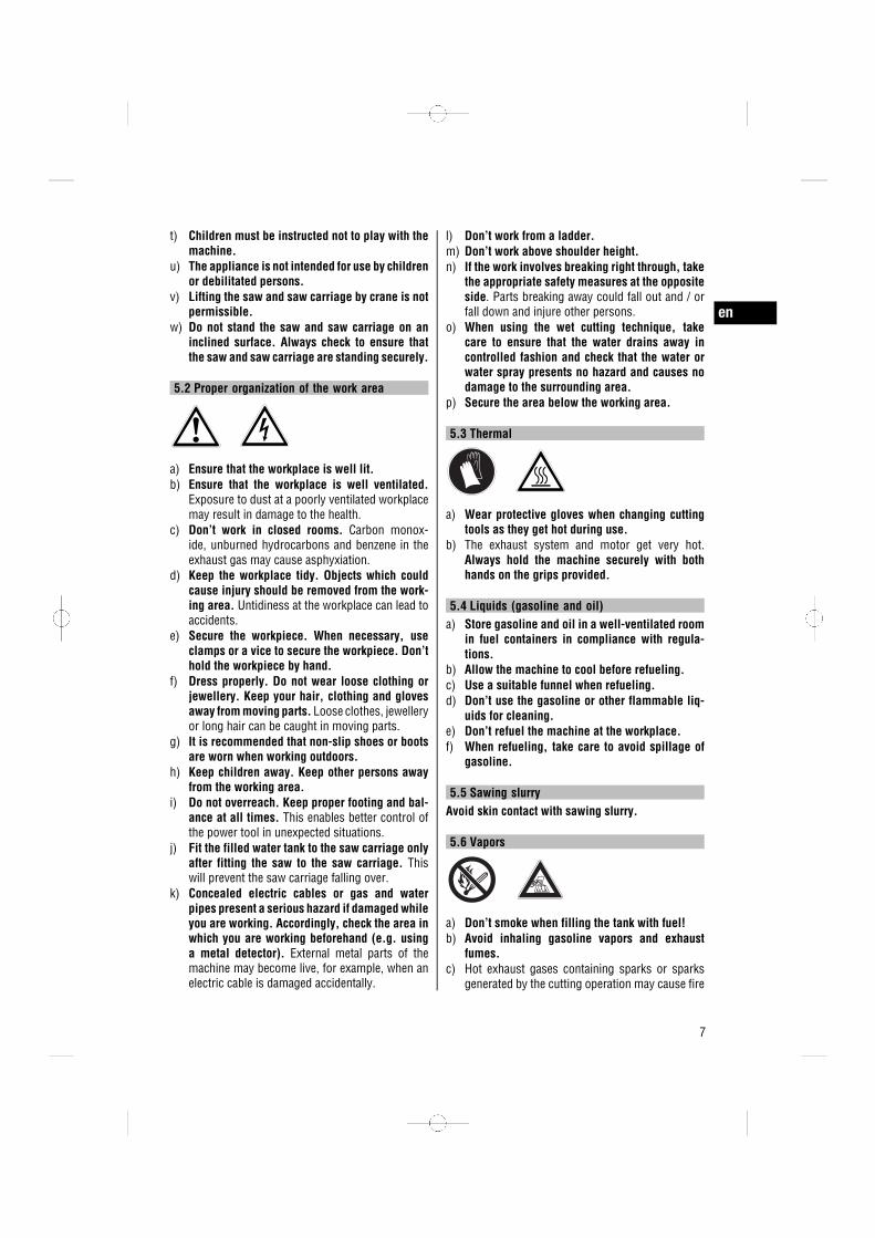
5.2 Proper organization of the work area
a) Ensure that the workplace is well lit.b) Ensure that the workplace is well ventilated.
Exposure to dust at a poorly ventilated workplacemay result in damage to the health.
c) Don’t work in closed rooms. Carbon monox-ide, unburned hydrocarbons and benzene in theexhaust gas may cause asphyxiation.
d) Keep the workplace tidy. Objects which couldcause injury should be removed from the work-ing area. Untidiness at the workplace can lead toaccidents.
e) Secure the workpiece. When necessary, useclamps or a vice to secure the workpiece. Don’thold the workpiece by hand.
f) Dress properly. Do not wear loose clothing orjewellery. Keep your hair, clothing and glovesaway from moving parts. Loose clothes, jewelleryor long hair can be caught in moving parts.
g) It is recommended that non-slip shoes or bootsare worn when working outdoors.
h) Keep children away. Keep other persons awayfrom the working area.
i) Do not overreach. Keep proper footing and bal-ance at all times. This enables better control ofthe power tool in unexpected situations.
j) Fit the filled water tank to the saw carriage onlyafter fitting the saw to the saw carriage. Thiswill prevent the saw carriage falling over.
k) Concealed electric cables or gas and waterpipes present a serious hazard if damaged whileyou are working. Accordingly, check the area inwhich you are working beforehand (e.g. usinga metal detector). External metal parts of themachine may become live, for example, when anelectric cable is damaged accidentally.
l) Don’t work from a ladder.m) Don’t work above shoulder height.n) If the work involves breaking right through, take
the appropriate safety measures at the oppositeside. Parts breaking away could fall out and / orfall down and injure other persons.
o) When using the wet cutting technique, takecare to ensure that the water drains away incontrolled fashion and check that the water orwater spray presents no hazard and causes nodamage to the surrounding area.
p) Secure the area below the working area.
5.3 Thermal
a) Wear protective gloves when changing cuttingtools as they get hot during use.
b) The exhaust system and motor get very hot.Always hold the machine securely with bothhands on the grips provided.
5.4 Liquids (gasoline and oil)a) Store gasoline and oil in a well-ventilated room
in fuel containers in compliance with regula-tions.
b) Allow the machine to cool before refueling.c) Use a suitable funnel when refueling.d) Don’t use the gasoline or other flammable liq-
uids for cleaning.e) Don’t refuel the machine at the workplace.f) When refueling, take care to avoid spillage of
gasoline.
5.5 Sawing slurryAvoid skin contact with sawing slurry.
5.6 Vapors
a) Don’t smoke when filling the tank with fuel!b) Avoid inhaling gasoline vapors and exhaust
fumes.c) Hot exhaust gases containing sparks or sparks
generated by the cutting operation may cause fire
en
7

or explosion. Take care to ensure that the sparksgenerated do not ignite flammable (gasoline,dry grass, etc.) or explosive (gas, etc.) sub-stances.
5.7 Dusts
a) Large quantities of dust hazardous to the healthare generated when cutting (especially when drycutting). The operator and bystanders must wearsuitable dust masks while the machine is in use.
b) Dust or vapors containing chemical substancesmay be generated when working on unknownmaterials. These substances could cause seriousdamage to the health. Obtain information abouthazards presented by the materials from theclient or the authorities responsible. The opera-tor of the machine and any bystanders must wearrespiratory protection that is approved for usein conjunction with the applicable substance.
c) To reduce the amount of dust generated whencutting mineral materials and asphalt, we rec-ommend use of the wet cutting technique.
d) WARNING: Some dust created by grinding,sanding, cutting and drilling contains chem-icals known to cause cancer, birth defects,infertility or other reproductive harm; or seri-ous and permanent respiratory or other injury.Some examples of these chemicals are: lead fromlead-based paints, crystalline silica from bricks,concrete and other masonry products and naturalstone, arsenic and chromium from chemically-treated lumber. Your risk from these exposuresvaries, depending on how often you do this typeof work. To reduce exposure to these chemi-cals, the operator and bystanders should workin a well-ventilated area, work with approvedsafety equipment, such as respiratory protec-tion appropriate for the type of dust generated,and designed to filter out microscopic particlesand direct dust away from the face and body.Avoid prolonged contact with dust. Wear pro-tective clothing and wash exposed areas withsoap and water. Allowing dust to get into yourmouth, nose, eyes, or to remain on your skin maypromote absorption of harmful chemicals.
5.8 Requirements to be met by usersa) Improve the blood circulation in your fingers by
relaxing your hands and exercising your fingersduring breaks between working.
b) Stay alert, watch what you are doing and usecommon sense when operating the machine.Don’t use the machine when you are tired orunder the influence of drugs, alcohol or medi-cation. A moment of inattention while operatingmachines may result in serious personal injury.
5.9 Safety warnings for abrasive cutting-offoperations
a) Check that the cutting disc is fitted in accordancewith the manufacturer’s instructions.
b) Cutting discs must be stored and handled care-fully in accordance with the manufacturer’s in-structions.
c) Use only cutting discs with a rated maximumpermissible speed which is at least as high asthe machine’s highest running speed.
d) Cutting discs which are damaged or out of round(causing vibration) must not be used.
e) The outside diameter and the thickness of thecutting disc must be within the capacity ratingof the machine. Incorrectly sized accessoriescannot be adequately guarded or controlled.
f) Don’t use toothed cutting discs (saw blades orsimilar). Blades or discs of this kind frequentlycause kickback or loss of control of the machine.
g) Guide the machine evenly and do not applylateral pressure to the cutting disc. Always bringthe machine into contact with the workpiece atright angles. Don’t attempt to alter the line ofcut by applying lateral pressure or by bendingthe cutting disc while cutting is in progress.This presents a risk of damaging or breaking thecutting disc.
h) Don’t attempt to brake the cutting disc with thehand.
i) The cutting disc and flange or any other acces-sory must fit the arbor of the machine exactly.Cutting discs or accessories with arbor holes thatdo not match the mounting hardware of the ma-
en
8

chine will run out of balance, vibrate excessivelyand may cause loss of control.
j) Always use undamaged disc mounting flangesof the correct diameter for the cutting discsused. Correctly sized flanges support the cut-ting disc and thus reduce the possibility of discbreakage.
k) When fitting the cutting disc, always take careto ensure that the disc’s specified direction ofrotation corresponds to the direction of rotationof the machine.
l) Store the cutting disc in accordance with themanufacturer’s recommendations. Incorrect orcareless storage may damage the cutting disc.
m) Don’t use cutting discs with a thickness greaterthan 5.5 mm (0.22").
n) Remove the cutting disc from the machine afteruse. The cutting disc may suffer damage if themachine is transported with the disc fitted.
o) Abrasive cutting discs for gasoline-powered cut-off saws which are used for wet cutting mustbe used up the same day as long periods of
exposure to moisture have a negative effect onthe strength of the disc.
p) Observe the expiry date for resin-bonded cuttingdiscs and don’t use the discs after this date.
q) Resharpen polished diamond segments (no di-amonds project from the segment matrix) bycutting with the disc in a very abrasive materialsuch as sandstone.
r) Don’t use damaged diamond cutting discs(cracks in the steel disc, broken or polishedsegments, damaged arbor hole, bent ordistorted steel disc, heavy discoloration due tooverheating, steel disc worn away beneath thesegments, diamond segments with no lateraloverhang, etc.)
5.10 Personal protective equipment
The user and any other persons in the vicinitymust wear suitable eye protection, a hard hat, earprotection, protective gloves and safety footwearwhile the machine is in use.
6. Before use
6.1 FuelNOTEThe two-stroke motor runs on a mixture of gasolineand oil. The quality of the fuel mixture decisivelyinfluences the running and life expectancy of themotor.
CAUTIONAvoid direct skin contact with gasoline.
CAUTIONEnsure that the workplace is well ventilated in orderto avoid breathing in gasoline fumes.
CAUTIONUse a fuel container that complies with the appli-cable regulations.
CAUTIONAlkylate gasoline does not have the same density(specific weight) as conventional gasoline. To avoiddamage when alkylate gasoline is used, the machinemust be readjusted by Hilti Service. Alternatively, theoil content can be increased to 4% (1:25).
6.1.1 Two-stroke oilUse Hilti two-stroke oil for air-cooled motors or agood quality two-stroke oil with the TC classification.
6.1.2 GasolineUse regular or super gasoline with an octane ratingof at least 90 ROZ.The alcohol content (e.g. ethanol, methanol...) of thefuel used must not exceed 10%, otherwise the lifeexpectancy of the motor will be greatly reduced.
en
9
5100 rpm
max.
6.1.3 Mixing fuelCAUTIONThe motor will suffer damage if run with fuel mixedin the wrong ratio or with unsuitable oil. Use thefollowing mix ratio with Hilti two-stroke oil: 1 partoil + 50 parts gasoline. Use the following mix ratiowith quality two-stroke oil with the TC classification:1 part oil + 25 parts gasoline.
1. Pour the required quantity of two-stroke oil intothe fuel container.
2. Add the gasoline to the fuel container.3. Close the cap on the fuel container.4. Mix the fuel by shaking the fuel container.
6.1.4 Storing the fuel mixtureCAUTIONPressure may build up in the fuel tank. Accordingly,take care when opening the fuel tank cap.
CAUTIONStore the fuel in a dry, well-ventilated room.
Mix only enough fuel for a few days’ use.Clean the fuel container occasionally.
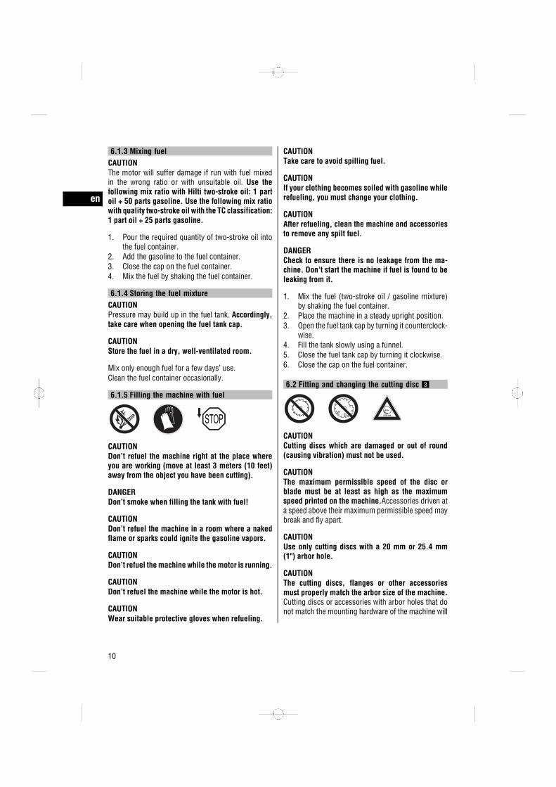
6.1.5 Filling the machine with fuel
CAUTIONDon’t refuel the machine right at the place whereyou are working (move at least 3 meters (10 feet)away from the object you have been cutting).
DANGERDon’t smoke when filling the tank with fuel!
CAUTIONDon’t refuel the machine in a room where a nakedflame or sparks could ignite the gasoline vapors.
CAUTIONDon’t refuel the machine while the motor is running.
CAUTIONDon’t refuel the machine while the motor is hot.
CAUTIONWear suitable protective gloves when refueling.
CAUTIONTake care to avoid spilling fuel.
CAUTIONIf your clothing becomes soiled with gasoline whilerefueling, you must change your clothing.
CAUTIONAfter refueling, clean the machine and accessoriesto remove any spilt fuel.
DANGERCheck to ensure there is no leakage from the ma-chine. Don’t start the machine if fuel is found to beleaking from it.
1. Mix the fuel (two-stroke oil / gasoline mixture)by shaking the fuel container.
2. Place the machine in a steady upright position.3. Open the fuel tank cap by turning it counterclock-
wise.4. Fill the tank slowly using a funnel.5. Close the fuel tank cap by turning it clockwise.6. Close the cap on the fuel container.
6.2 Fitting and changing the cutting disc 3
CAUTIONCutting discs which are damaged or out of round(causing vibration) must not be used.
CAUTIONThe maximum permissible speed of the disc orblade must be at least as high as the maximumspeed printed on the machine.Accessories driven ata speed above their maximum permissible speed maybreak and fly apart.
CAUTIONUse only cutting discs with a 20 mm or 25.4 mm(1") arbor hole.
CAUTIONThe cutting discs, flanges or other accessoriesmust properly match the arbor size of the machine.Cutting discs or accessories with arbor holes that donot match the mounting hardware of the machine will
en
10
run out of balance, vibrate excessively and may causeloss of control.
CAUTIONDon’t use synthetic resin-bonded fiber-reinforcedcutting discs that have exceeded their use-by date.
CAUTIONDon’t use damaged diamond cutting discs (cracks inthe steel disc, broken or polished segments, dam-aged arbor hole, bent or distorted steel disc, heavydiscoloration due to overheating, steel disc wornaway beneath the segments, diamond segmentswith no lateral overhang, etc.)
1. Insert the locking pin in the hole in the drive beltcover and turn the cutting disc until the lockingpin engages.
2. Use the wrench to release the clamping screw byturning it counterclockwise.
3. Remove the clamping flange and the cutting disc.4. Check that the mounting bore of the cutting disc
to be fitted corresponds with the centering collarof the cutting disc mounting flange. The mount-ing flange is provided with a 20 mm diametercentering collar on one side and a 25.4 mm (1")diameter centering collar on the opposite side.
5. Clean the clamping and centering surfaces onthe machine and on the cutting disc.
6. CAUTION Take care to ensure that the directionof rotation of the cutting disc (indicated by anarrow) matches the direction of rotation shownon the machine.Place the cutting disc on the centering collar ofthe clamping flange.
7. Place the clamping flange on the drive arborand tighten the cutting disc clamping screw byturning it clockwise.
8. Insert the locking pin in the hole in the drive beltcover and turn the cutting disc until the lockingpin engages.
9. Tighten the cutting disc clamping screw to atorque of 25 Nm.
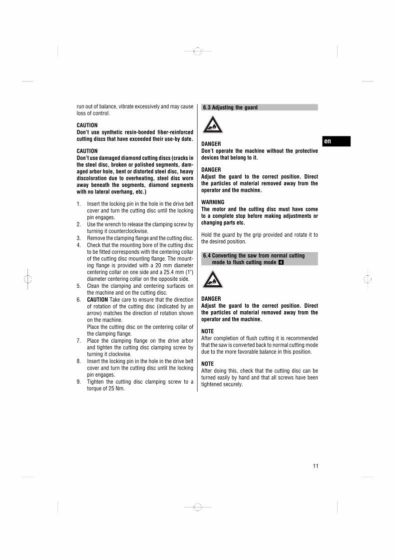
6.3 Adjusting the guard
DANGERDon’t operate the machine without the protectivedevices that belong to it.
DANGERAdjust the guard to the correct position. Directthe particles of material removed away from theoperator and the machine.
WARNINGThe motor and the cutting disc must have cometo a complete stop before making adjustments orchanging parts etc.
Hold the guard by the grip provided and rotate it tothe desired position.
6.4 Converting the saw from normal cuttingmode to flush cutting mode 4
DANGERAdjust the guard to the correct position. Directthe particles of material removed away from theoperator and the machine.
NOTEAfter completion of flush cutting it is recommendedthat the saw is converted back to normal cutting modedue to the more favorable balance in this position.
NOTEAfter doing this, check that the cutting disc can beturned easily by hand and that all screws have beentightened securely.
en
11

DANGERDon’t operate the machine without the protectivedevices that belong to it.
In order to facilitate cutting as closely as possible toedges and walls etc., the forward section of the sawarm can be turned and fitted in the reversed positionso that the cutting disc, when seen from behind, ispositioned to the right of the saw arm.1. Remove the spray jets from the guard.2. Slacken the three clamping nuts on the forward
section of the saw arm approx. one completeturn.
3. Release the tension on the drive belt by turningthe belt tensioning cam counterclockwise care-fully as far as it will go (until resistance is felt,i.e. approx. ¼ of a turn).
4. Remove the three clamping nuts and the twosecuring screws from the forward section of thesaw arm, then remove the drive belt cover andthe forward section of the saw arm.
5. Release the four securing screws on the reardrive belt cover and remove the cover.
6. Remove the stop screw that limits rotation of theforward section of the saw arm.
7. Place the drive belt carefully over the drive pulley.8. Fit the forward section of the saw arm onto the
rear section of the saw arm. Fit only the middleclamping nut. Tighten the nut only finger-tight.
9. Rotate the disc guard until the opening is at therear.
10. Tension the drive belt by turning the belt tension-ing cam clockwise carefully as far as it will go(until resistance is felt, i.e. approx. ¼ of a turn).
11. Secure the forward drive belt cover with the twoclamping nuts and two securing screws.
12. Tighten the three clamping nuts securely (18Nm).
13. Fit the rear drive belt cover and secure it with thefour screws.
14. Rotate the disc guard until the opening is at thefront.
15. Fit the spray jets in the openings at the front ofthe blade guard.
6.5 Locking rotary movement of the guidewheels 5
WARNINGWhen working on roofs, scaffolds and/or slightslopes, always lock the guide wheels to prevent thesaw rolling away inadvertently and possibly falling.Use the built-in safety feature which allows youto lock the wheels by fitting them in the reversedposition (turned through 180°).
1. Release the guide wheel mounting screws andremove the guide wheels.
2. Reverse the guide wheels (turn through 180°)and refit the mounting screws.
3. Check that the guide wheels are mounted se-curely.
6.6 Saw carriage 6
NOTEWe recommend use of the saw carriage when themachine is used extensively for floor sawing.
NOTEEspecially when using the machine in this config-uration for the first time, check to ensure that thethrottle cable is correctly adjusted. When the throttlecontrol is pressed fully, the machine must run up tomaximum speed. If this is not the case, the throttlecable can be readjusted by way of the cable tensioner.
CAUTIONSwitch off the saw at the stop switch immediately ifthe throttle cable on the saw carriage gets stuck.
DANGERBefore starting the engine, check that the saw iscorrectly secured to the saw carriage.
1. Move the cutting depth adjustment lever into theupper position.
2. Open the hold-down device by releasing thescrew knob.
3. Fit the saw into the forward mount with thewheels as shown and swing the grip of the sawunder the hold-down device.
4. Secure the saw by tightening the screw knob.5. Fit the water tank after filling it.6. Adjust the grip to a convenient working height.7. Adjust the guard to the correct position.
en
12

7. Operation
7.1 Starting the motor 7
CAUTIONWorking on the material may cause it to splinter.Wear eye protection and protective gloves. Wearbreathing protection if no dust removal system isused. Splintering material presents a risk of injury tothe eyes and body.
CAUTIONThe power tool and the cutting operation generatenoise. Wear ear protectors. Exposure to noise cancause hearing loss.
CAUTIONThe cutting disc and parts of the machine get hot dur-ing use. Wear protective gloves when changing thecutting disc. Touch the power tool only at the gripsprovided. You may otherwise burn your hands. Takecare to ensure that the machine, when hot, does notcome into contact with flammable materials duringtransport or storage.
WARNINGKeep other persons approx. 15 m away from yourworkplace. Pay special attention to the workingarea behind you.
DANGERDon’t work in closed rooms. Carbon monoxide, un-burned hydrocarbons and benzene in the exhaust gasmay cause asphyxiation.
WARNINGWhen the motor is idling, the cutting disc mustcome to a complete stop. If this is not the case, theidling speed must be reduced accordingly. If this isnot possible or does not achieve the desired result,the machine must be returned for repair.
WARNINGIf you notice that the throttle trigger has jammed,stop the motor immediately by operating the on /off switch.
WARNINGAfter fitting a new cutting disc, the machine mustbe allowed to run at full speed under no load forapprox. 1 minute.
WARNINGBefore using the machine, check to ensure that thestart / stop switch functions correctly. The motormust stop running when the switch is moved to the“stop” position.
1. Stand the machine on a solid surface on thefloor.
2. Move the start / stop switch to the “start” posi-tion.
3. Press the fuel pump button (P) 2 to 3 times (untilthe pump button is seen to be completely filledwith fuel).
4. Press the decompression valve.5. If the motor is cold, pull the choke lever up-
wards. This activates the choke and engages halfthrottle.
6. If the motor is hot, pull the choke lever up andthen push it back down. This engages half throttle(with no choke).
7. Check that the cutting disc is free to rotate.8. Hold the forward grip securely with the left hand
and place your right foot in the lower section ofthe rear grip.
9. Pull the starter handle slowly with your righthand until resistance is felt.
10. Pull the starter handle vigorously.11. When the motor fires for the first time (after 2 to
5 pulls of the starter), move the choke lever backto its original position.
12. Repeat this procedure, with the choke disen-gaged, until the motor starts.NOTE The motor will flood if the starting proce-dure is repeated too many times with the chokeengaged.
en
13

13. Press the throttle as soon as the motor starts.This disengages the half-throttle position andthe choke (if previously engaged), and the motorthen runs at idling speed when the throttle isreleased.
7.2 Cutting techniquesDANGERAlways hold the saw and the saw carriage securelywith both hands on the grips provided. Keep thegrips dry, clean and free from oil and grease.
DANGERCheck that no persons are present within the work-ing area and, in particular, in the area ahead of thesaw (in the cutting direction).
DANGERGuide the machine evenly and do not apply lat-eral pressure to the cutting disc. Always bring themachine into contact with the workpiece at rightangles. Don’t attempt to alter the line of cut byapplying lateral pressure or by bending the cuttingdisc while cutting is in progress. This presents arisk of damaging or breaking the cutting disc.
CAUTIONSecure the workpiece and the part to be cut off inorder to prevent uncontrolled movement.
NOTEAlways apply full throttle when cutting.
NOTEAvoid making excessively deep cuts. Cutting throughthick workpieces should be accomplished, as far aspossible, by making a several cuts.
7.2.1 Avoiding stalling 8
CAUTIONAvoid applying excessive pressure when cuttingand don’t allow the cutting disc to stick and stall.Don’t attempt to cut to great depth immediately.Application of excessive pressure increases the riskof cutting disc distortion. Allowing the cutting disc tostick or stall increases the probability of kickback ordisc breakage.
CAUTIONSupport slabs or large workpieces so that the kerfremains open during the cutting operation.
7.2.2 Avoiding kickback 9
CAUTIONAlways bring the machine into contact with theworkpiece from above. Allow the cutting disc tocontact the workpiece only at a point below itsrotational axis.
CAUTIONTake special care when inserting the cutting disc inan existing kerf.
7.3 Stopping the motorWARNINGIf the motor cannot be stopped by operating the on/ off switch, the motor must be stopped, if need be,by pulling the choke lever.
WARNINGDo not lay the machine down until the cutting dischas stopped rotating. The machine must always bestored and transported in an upright position.
1. Release the throttle trigger.2. Move the start / stop switch to the “stop” posi-
tion.
8. Care and maintenance
WARNINGSet the switch to “stop” before carrying out anymaintenance or repairs and before cleaning themachine.
8.1 Maintenance
8.1.1 Each day before useCheck that the machine is complete and in faultlesscondition. Have it repaired if necessary.Check the machine for leakage. Have it repaired ifnecessary.
en
14
Check the machine for dirt and dust and clean it ifnecessary.Check that all operating controls function correctly.Have them repaired if necessary.Check that the cutting disc is in faultless condition.Replace it if necessary.
8.1.2 Every 6 monthsCheck the tightness of all screws and nuts accessiblefrom the outside.Check that the fuel filter is clean (no dirt or deposits)and replace it if necessary.Retension the drive belt if it slips when the cuttingdisc is under load.
8.1.3 When necessaryCheck the tightness of all screws and nuts accessiblefrom the outside.Replace the air filter if the machine doesn’t start ormotor performance drops noticeably.Check that the fuel filter is clean (no dirt or deposits)and replace it if necessary.Clean or replace the spark plug if the machine doesn’tstart or is difficult to start.Retension the drive belt if it slips when the cuttingdisc is under load.Readjust the motor idling speed if the cutting discdoesn’t stop rotating when the machine is idling.
8.2 Replacing the air filter 10 11
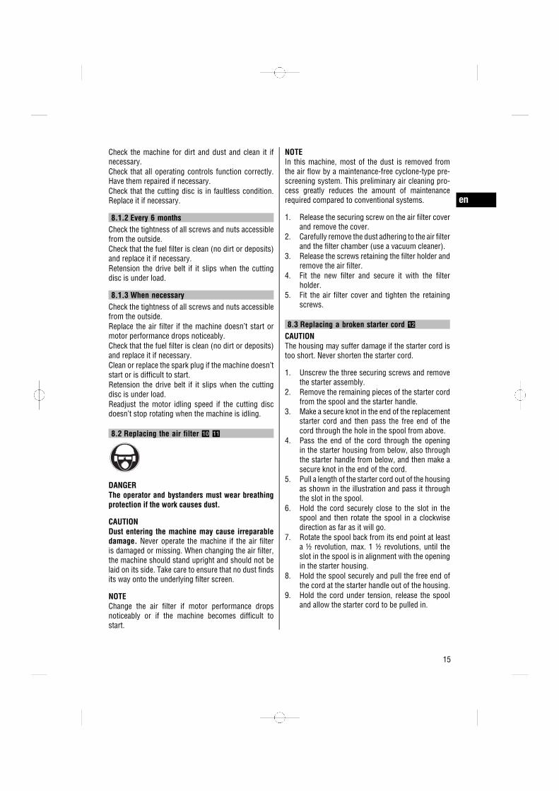
DANGERThe operator and bystanders must wear breathingprotection if the work causes dust.
CAUTIONDust entering the machine may cause irreparabledamage. Never operate the machine if the air filteris damaged or missing. When changing the air filter,the machine should stand upright and should not belaid on its side. Take care to ensure that no dust findsits way onto the underlying filter screen.
NOTEChange the air filter if motor performance dropsnoticeably or if the machine becomes difficult tostart.
NOTEIn this machine, most of the dust is removed fromthe air flow by a maintenance-free cyclone-type pre-screening system. This preliminary air cleaning pro-cess greatly reduces the amount of maintenancerequired compared to conventional systems.
1. Release the securing screw on the air filter coverand remove the cover.
2. Carefully remove the dust adhering to the air filterand the filter chamber (use a vacuum cleaner).
3. Release the screws retaining the filter holder andremove the air filter.
4. Fit the new filter and secure it with the filterholder.
5. Fit the air filter cover and tighten the retainingscrews.
8.3 Replacing a broken starter cord 12
CAUTIONThe housing may suffer damage if the starter cord istoo short. Never shorten the starter cord.
1. Unscrew the three securing screws and removethe starter assembly.
2. Remove the remaining pieces of the starter cordfrom the spool and the starter handle.
3. Make a secure knot in the end of the replacementstarter cord and then pass the free end of thecord through the hole in the spool from above.
4. Pass the end of the cord through the openingin the starter housing from below, also throughthe starter handle from below, and then make asecure knot in the end of the cord.
5. Pull a length of the starter cord out of the housingas shown in the illustration and pass it throughthe slot in the spool.
6. Hold the cord securely close to the slot in thespool and then rotate the spool in a clockwisedirection as far as it will go.
7. Rotate the spool back from its end point at leasta ½ revolution, max. 1 ½ revolutions, until theslot in the spool is in alignment with the openingin the starter housing.
8. Hold the spool securely and pull the free end ofthe cord at the starter handle out of the housing.
9. Hold the cord under tension, release the spooland allow the starter cord to be pulled in.
en
15

10. Pull the starter cord out as far as it will go andcheck to ensure that the spool can be turnedby hand at least a further ½ turn in a clock-wise direction. If this is not possible, springtension must be reduced by one revolution in acounterclockwise direction.
11. Fit the starter assembly to the machine and pressit down gently.Pull the starter cord slightly until the couplingengages and the starter assembly is fully seated.
12. Secure the starter assembly with the three re-taining screws.
8.4 Checking and replacing the fuel filter 13
NOTECheck the condition of the fuel filter regularly.
NOTEWhen refueling the machine, take care to ensure thatno dirt or foreign matter finds its way into the fueltank.
1. Remove the cap from the fuel tank.2. Pull the fuel filter out of the fuel tank.3. Check the condition of the fuel filter.
The filter must be replaced if badly soiled.4. Push the fuel filter back into the fuel tank.5. Close the cap on the fuel tank.
8.5 Cleaning the spark plug / setting the sparkplug gap / replacing the spark plug 14
CAUTIONThe spark plug and parts of the motor may be hotimmediately after the machine has been running. Toavoid burning your hands, wear suitable protectivegloves or allow the machine to cool down beforetouching its parts.
Use only spark plugs of the type NGK‑CMR7A-5.1. Use a gentle twisting motion to pull the cable
connector off the spark plug.2. Use the spark plug wrench to unscrew and re-
move the spark plug from the cylinder.3. If necessary, clean the spark plug electrode with
a soft wire brush.4. Check the spark plug gap (0.5 mm) with the aid
of a feeler gauge and reset it to the correct gap ifnecessary.
5. Fit the ignition cable connector to the spark plugand hold the threaded section of the spark plugagainst the cylinder.
6. Move the start / stop switch to the “start” posi-tion.
7. CAUTION Avoid touching the spark plug elec-trode.Pull the starter cord (press the decompressionvalve first).An ignition spark must now be clearly visible.
8. Use the spark plug wrench to screw the sparkplug into the cylinder (12 Nm).
9. Fit the ignition cable connector to the spark plug.
8.6 Retensioning the drive belt 15
CAUTIONA slack drive belt can damage the machine. Reten-sion the drive belt if it slips when a load is applied tothe cutting disc.
NOTEThe drive belt must be replaced as soon as thewear mark on the saw arm becomes visible afterretensioning.
This machine is equipped with a semi-automatic,spring-assisted drive belt tensioning system.1. Slacken the three clamping nuts on the forward
section of the saw arm approx. one completeturn.
2. After releasing the nuts, the drive belt is ten-sioned automatically by spring pressure.
3. Retighten the three clamping nuts securely (18Nm).
8.7 Changing the drive belt 16
NOTEAfter doing this, check that the cutting disc can beturned easily by hand and that all screws have beentightened securely.
1. Slacken the three clamping nuts on the forwardsection of the saw arm approx. one completeturn.
2. Release the tension on the drive belt by turningthe belt tensioning cam counterclockwise care-fully as far as it will go (until resistance is felt,i.e. approx. ¼ of a turn).
3. Remove the upper and lower clamping nuts andthe two securing screws from the forward sectionof the saw arm and remove the drive belt cover.
4. Release the four securing screws on the reardrive belt cover and remove the cover.
en
16
5. Remove the defective drive belt. Place the newdrive belt carefully over the two drive pulleys.
6. Tension the drive belt by turning the belt tension-ing cam clockwise carefully as far as it will go(until resistance is felt, i.e. approx. ¼ of a turn).
7. Fit the rear drive belt cover and secure it with thefour screws.
8. Secure the forward drive belt cover with the twoclamping nuts and two securing screws.
9. Tighten the three clamping nuts securely (18Nm).
8.8 Adjusting the carburetor 17
CAUTIONTampering with the carburetor settings may causedamage to the motor.
The carburetor of this machine (jets H and L) has beenfactory set for optimum performance and sealed toprevent tampering. The idling speed of the machine(jet T) may be adjusted by the user. All other adjust-ments must be carried out at a Hilti service center.NOTEUse a suitable flat screwdriver (tip width 4 mm/ ⁵/₃₂ ")and do not force the adjusting screw beyond itsintended adjustment range.
1. Clean the air filter.2. Allow the machine to run until it reaches its
normal operating temperature.3. Adjust the idling speed jet (T) so that the motor
runs smoothly when idling but the cutting discdoes not begin to rotate.
8.9 CleaningCareful cleaning of the machine is one of the mainprerequisites for trouble-free, reliable operation.Heavy dirt and dust deposits on the motor and in thecooling openings may lead to overheating.Don’t permit foreign objects to enter the interior ofthe machine.Don’t use a high pressure jet system or running waterfor cleaning.Don’t use cleaning agents which contain silicone.Clean the exterior of the machine at regular intervalswith a slightly damp cloth or a dry brush.Check that all grips are clean, dry and free from oiland grease.
8.10 MaintenanceCheck all external parts of the machine and theaccessories for damage at regular intervals and checkthat all controls operate faultlessly. Don’t operate themachine if parts are damaged or when the controlsdo not function faultlessly. If necessary, the machineshould be repaired by Hilti Service.
8.11 Checking the power tool after care andmaintenance
After carrying out care and maintenance, check thatall protective and safety devices are fitted and thatthey function faultlessly.
8.12 Transporting the machine in a vehicle
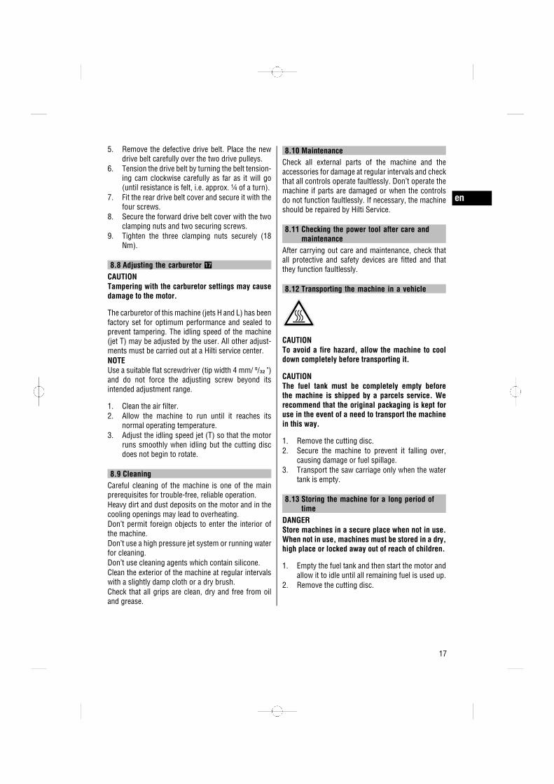
CAUTIONTo avoid a fire hazard, allow the machine to cooldown completely before transporting it.
CAUTIONThe fuel tank must be completely empty beforethe machine is shipped by a parcels service. Werecommend that the original packaging is kept foruse in the event of a need to transport the machinein this way.
1. Remove the cutting disc.2. Secure the machine to prevent it falling over,
causing damage or fuel spillage.3. Transport the saw carriage only when the water
tank is empty.
8.13 Storing the machine for a long period oftime
DANGERStore machines in a secure place when not in use.When not in use, machines must be stored in a dry,high place or locked away out of reach of children.
1. Empty the fuel tank and then start the motor andallow it to idle until all remaining fuel is used up.
2. Remove the cutting disc.
en
17

3. Clean the machine thoroughly and grease themetal parts.
4. Remove the spark plug.5. Pour a little two-stroke oil into the cylinder (1 to
2 teaspoons).
6. Pull the starter handle a few times.This will distribute the oil in the cylinder.
7. Replace the spark plug.8. Wrap the machine in plastic foil.9. Put the machine into storage.
9. Troubleshooting
Fault Possible cause Remedy
Cutting disc slows down orstops completely while cut-ting
Excessive cutting pressure applied(cutting disc sticks and stalls in thekerf).
Reduce cutting pressure and guidethe machine in a straight line.
Drive belt tension too low or thedrive belt is broken.
Re-tension the drive belt or fit anew belt.
Cutting disc incorrectly fitted or nottightened properly.
Check that the disc is fitted andtightened correctly.
Cutting disc direction of rotation isincorrect.
Check the direction of rotation andcorrect if necessary.
The forward section of the saw armis loose.
Tighten the clamping nuts.
High vibration, disc wandersoff the cutting line
Cutting disc incorrectly fitted or nottightened properly.
Check that the disc is fitted andtightened correctly.
Cutting disc is damaged (or unsuit-able specification, cracked, seg-ments missing, bent, overheated,deformed, etc.).
Fit a new cutting disc.
The centering bushing is fitted in-correctly.
Check that the mounting bore ofthe cutting disc to be fitted corre-sponds with the centering collar ofthe cutting disc mounting flange.
Saw doesn’t start or is diffi-cult to start
The fuel tank is empty (no fuel inthe carburetor).
Fill the fuel tank.
Air filter clogged with dirt or dust. Replace the air filter.The motor is flooded (spark plugwet).
Dry the spark plug and cylinder(remove the spark plug).Disengage the choke lever and re-peat the starting procedure severaltimes.
Wrong fuel mixture. Empty the fuel tank and flush outthe tank and fuel lines. Fill the tankwith the correct fuel.
Air in the fuel line (no fuel reachingthe carburetor).
Remove the air from the fuel lineby operating the fuel pump severaltimes.
The fuel filter is dirty or blocked(no fuel or too little fuel reachingthe carburetor).
Clean the tank and fit a new fuelfilter.
en
18

Fault Possible cause Remedy
Saw doesn’t start or is diffi-cult to start
No ignition spark visible or sparkis too weak (when spark plug isremoved).
Clean the spark plug to removecarbon deposits.Check the spark plug gap and ad-just it if necessary.Fit a new spark plug.Check the ignition coil, cable, con-nectors and switch and replace theparts if necessary.
Motor compression is too low. Check the motor compression and,if necessary, replace worn parts(piston rings, cylinder, etc.
Very low temperatures. Allow the machine to warm upslowly to room temperature andrepeat the starting procedure.
Dirt or dust in the spark guard /exhaust exit.
Clean the parts.
The decompression valve is stiff tooperate.
Release the valve.
Low motor power / poor cut-ting performance
Air filter clogged with dirt or dust. Replace the air filter.No ignition spark visible or sparkis too weak (when spark plug isremoved).
Clean the spark plug to removecarbon deposits.Check the spark plug gap and ad-just it if necessary.Fit a new spark plug.Check the ignition coil, cable, con-nectors and switch and replace theparts if necessary.
The wrong fuel or dirt and water inthe fuel tank.
Flush out the fuel system, replacethe fuel filter and refill with fuel.
The disc specification is unsuitablefor the material to be cut.
Change the specification or requestadvice from Hilti.
Drive belt or cutting disc slips. Check the drive belt tension anddisc clamping parts and eliminatethe fault.
Motor compression is too low. Check the motor compression and,if necessary, replace worn parts(piston rings, cylinder, etc.
The machine is operated or han-dled incorrectly (excessive cut-ting pressure applied, cutting discoverheats, disc sticks in the kerf,unsuitable disc type, etc.).
Observe the information providedin the operating instructions.
Working at an altitude of more than1500 m (4900 ft) above sea level.
Have the carburetor adjusted byHilti Service.
Incorrect carburetor setting (fuel /air mixture).
Have the carburetor adjusted byHilti Service.
en
19

Fault Possible cause Remedy
Cutting disc rotates while themotor is idling
Idling speed is too high. Check the idling speed and adjust ifnecessary.
The half-throttle position is en-gaged.
Disengage the half-throttle setting.
Faulty centrifugal clutch. Replace the centrifugal clutch.Starter unit doesn’t work The clutch claws are not engaging. Clean the parts so that they can
move freely.
10. Disposal
Most of the materials from which Hilti machines or appliances are manufactured can be recycled. Thematerials must be correctly separated before they can be recycled. In many countries, Hilti has already madearrangements for taking back old machines and appliances for recycling. Ask Hilti customer service or yourHilti representative for further information.
NOTEDisposing of slurry directly into rivers, lakes or the sewerage system without suitable pretreatment presentsenvironmental problems. Ask the local public authorities for information about current regulations.
1. Collect the slurry (e.g. using a wet-type industrial vacuum cleaner)2. Allow the slurry to settle and dispose of the solid material at a construction waste disposal site (the
addition of a flocculent may accelerate the separation process).3. The remaining water (alkaline, pH value > 7) must be neutralized by the addition of an acidic neutralizing
agent or diluted with a large volume of water before it is allowed to flow into the sewerage system.
11. Federal emission control warranty statementYour warranty rights and obligationsThe U.S. Environmental Protection Agency (EPA), theCalifornia Air Resources Board (CARB), and Hilti arepleased to explain the Emission Control System War-ranty applicable to your small non-road engine. InU.S. and Canada, small non-road engines must bedesigned, built and equipped to meet the stringentfederal antismog standards. The equipment enginemust be free from defects in materials and work-manship which cause it to fail to conform with U.S.EPA standards for the first two years of engine usefrom the date of sale to the ultimate purchaser. Hiltimust warrant the emission control system on yoursmall non-road engine for the periods of time listedabove, provided there has been no abuse, neglect orimproper maintenance of your unit. Your emission
control system includes parts such as the carburetorand the ignition system. Where a warrantable condi-tion exists, Hilti will repair your small non-road engineat no cost to you. Expenses covered under warrantyinclude diagnosis, parts and labor.
Manufacturer’s warranty coverageAll 2001 and later small non-road engines are war-ranted to meet the applicable EPA and CARB require-ments for two years. If any emission related part onyour engine (as listed above) is defective, the part willbe repaired or replaced by Hilti.
Owner’s warranty responsibilitiesAs a small non-road engine owner, you are respon-sible for performance of the required maintenance as
en
20

defined by Hilti in the owner’s manual. Hilti recom-mends that you retain all receipts covering mainte-nance on your small non-road engine, but Hilti cannotdeny warranty solely for the lack of receipts or foryour failure to ensure the performance of all sched-uled maintenance. Any replacement part or servicethat is equivalent in performance and durability maybe used in non-warranty maintenance or repairs, andshall not reduce the warranty obligations of the en-gine manufacturer. As the small non-road equipmentengine owner, you should be aware, however, thatHilti may deny you warranty coverage if your smallnon-road engine or a part en of it has failed due toabuse, neglect, improper maintenance, unapprovedmodifications or the use of parts not made or ap-proved by the original equipment manufacturer. Youare responsible for presenting your small non-roadengine to Hilti as soon as the problem exists. Thewarranty repairs should be completed in a reasonableamount of time, not to exceed 30 days.
CoverageHilti warrants to the ultimate purchaser and each sub-sequent purchaser that your small non-road equip-ment engine will be designed, built equipped, at thetime of sale, to meet all applicable regulations. Hiltialso warrants to the initial purchaser and each subse-quent purchaser that the emission-related warrantedparts are free from defects in material and work-manship which cause the engine to fail to conformwith applicable regulations for a period of two years.These warranty periods will begin on the date smallnon-road equipment engine is purchased by the ini-tial purchaser. If any emission-related part on yourengine is defective, the part will be replaced by Hilti
at no cost to the owner. Hilti shall remedy warrantydefects at authorized Hilti service and repair centers.Any authorized work done at an authorized Hilti ser-vice and repair center shall be free of charge to theowner if it is determined that a warranted part isdefective. Any manufacturer-approved or equivalentreplacement part may be used for any warranty main-tenance or repairs on emission-related parts, andmust be provided free of charge to the owner if thepart is still under warranty. Hilti is liable for damagesto other engine components caused by the failure ofa warranted part still under warranty. The CaliforniaAir Resources Board’s Emission Warranty Part Listspecifically defines the emission related, warrantedparts. These warranted parts are: the carburetor as-sembly, coil assembly, rotor, spark plug, air filter,fuel filter, breather manifold and the gaskets.
Maintenance requirementsThe owner is responsible for performing the requiredmaintenance as defined by Hilti in the owner’s manual.
LimitationsThe Emission Control Systems Warranty shall notcover any of the following: a) repair or replacementrequired because of misuse, neglect or lack of re-quired maintenance, b) repairs improperly performedor replacements not conforming to Hilti specificationsthat adversely affect performance and/or durability,and alterations or modifications not recommended orapproved in writing by Hilti, and c) replacement ofparts and other services and adjustments necessaryfor required maintenance at and after this first sched-uled replacement point. Except as set forth above, thewarranty terms set forth in section 12 below, apply.
12. Manufacturer’s warrantyHilti warrants that the tool supplied is free of defectsin material and workmanship. This warranty is validso long as the tool is operated and handled correctly,cleaned and serviced properly and in accordance withthe Hilti Operating Instructions, and the technicalsystem is maintained. This means that only originalHilti consumables, components and spare parts maybe used in the tool.
This warranty provides the free-of-charge repair orreplacement of defective parts only over the entirelifespan of the tool. Parts requiring repair or replace-
ment as a result of normal wear and tear are notcovered by this warranty.
Additional claims are excluded, unless stringent na-tional rules prohibit such exclusion. In particular,Hilti is not obligated for direct, indirect, inciden-tal or consequential damages, losses or expensesin connection with, or by reason of, the use of,or inability to use the tool for any purpose. Im-plied warranties of merchantability or fitness for aparticular purpose are specifically excluded.
en
21

For repair or replacement, send the tool or relatedparts immediately upon discovery of the defect tothe address of the local Hilti marketing organizationprovided.
This constitutes Hilti’s entire obligation with regardto warranty and supersedes all prior or contempo-raneous comments and oral or written agreementsconcerning warranties.
en
22