Embed Size (px)
Citation preview

OPERATION/ MAINTENANCE MANUAL
208 VERSION


ARC 656 PRO WELD
TABLE OF CONTENTS
Section 1 SAFETY PRECAUTIONS
PAGE 1.0 INTRODUCTION....................................................... 1 2.0 WARRANTY............................................................... 1 3.0 UNPACKING YOUR UNIT....................................... 1 4.0 SUGGESTED SAFETY PRECAUTIONS................ 1 4.1 PERSONAL SAFETY PRECAUTIONS……………. 1,2 4.2 POWER SUPPLY SAFETY PRECAUTIONS……… 2 5.0 GENERAL DESCRIPTION....................................... 2 6.0 ELECTRICAL INPUT REQUIREMENT................. 2 7.0 CONTROL PANEL DESCRIPTION...................... 3 8.0 WELD GUN SETUP................................................... 3 8.1 PLUNGE LENGTH..................................................... 3 8.2 CHECKING GUN LIFT............................................. 4 9.0 SETTING UP THE POWER SOURCE.................... 5 9.1 CONNECTIONS AND SETTINGS…………………. 5 9.2 WELD TEST AND INSPECTION………………….. 5 10.0 MAINTENANCE.............................................................. 6 10.1 WELD CABLES……………..………………………….. 6 10.2 INTERNAL CLEANING……………………………… 6 11.0 TROUBLE SHOOTING……………………………….. 7 12.0 PARTS LIST……………………………………. 8,9,10
LIST OF FIGURES
1 JUMPER LINK ARRANGEMENT....…….................... 2 2 GROUND CONNECTION……...................................... 3 3 CONTROL PANEL………….......................................... 3 4 GUN SET-UP……………................................................. 4 5 WELD INSPECTION...................................................... 5 6 FUSE BLOCK……….………………………….............. 6 7 OUTSIDE OF ARC-656………….................................... 8 8 INSIDE OF ARC-656…………….................................... 9 9 WELD CONTROL PCB……….…................................. 10

ARC 656 PRO WELD

ARC 656 PRO WELD

ARC 656 PRO WELD

ARC 656 PRO WELD
ARC 656 PRO WELD
1.0 INTRODUCTION
Your new stud welding equipment has been carefully con-structed using the finest components and material available. Used properly, this equipment will give you many years of profitable, efficient service.
The system incorporates the latest in engineering advances for complete, reliable end welding of mild steel, stainless steel and aluminum fasteners.
A careful study of this manual will enable you to understand how the welder operates to insure proper performance under all conditions.
2.0 WARRANTY
The electrical and mechanical components of the stud welder are thoroughly performance inspected prior to assem-bly in the welder. The assembled welder is completely per-formance checked. The welder is delivered to you in func-tional electro-mechanical condition.
All parts used in the assembly of the welder and its ac-cessories are fully warranted for a period of 1 YEAR from the date of delivery. In addition, the welding capacitors are war-ranted for a period of 1 YEAR from the date of delivery. The printed circuit boards used in all proweld equipment are war-ranted for a period of 3 years.
Under the warranty, the manufacturer reserves the right to repair or replace, at their option, defective parts which fail during the guarantee period. Notice of any claim for warranty repair or replacement must be furnished to the manufacturer by the purchaser within ten (10) days after the defect is first discovered. The manufacturer does not assume any liability for paying shipping cost or any labor or materials furnished where such cost are not expressly authorized in writing.
The manufacturer does not warrant any parts or acces-sories against failures resulting from misuse, abuse, improper installation, maladjustment, or use not in accordance with the operating instructions furnished by the manufacturer. The warranty is valid only when studs are purchased from sources approved by the manufacturer or are of identical specifica-tions to the manufacturer’s
3.0 UNPACKING YOUR UNIT
Upon receipt of your unit, place it as close as possible to the point of installation before unpacking it. Once the unit is un-packed, it is recommended that you inspect it for any physical damage that may have occurred in shipping.
Your unit has been completely assembled and inspected at the factory. Upon receipt, the unit must be hooked up to the recommended incoming power before welding.
Place the unit in a large enough area to provide adequate ven-tilation. Do not restrict the air flow around the front louvers or from the fan at the rear of the unit. Do not allow water to enter the unit in any way.
4.0 SUGGESTED SAFETY PRECAUTIONS
In any welding operation, it is the responsibility of the welder to observe all safety rules to insure his or her personal safety and to protect those working in the area.
Reference is directed without endorsement or recommenda-tion to ANSI Z49.1, Safety in Welding and Cutting, and to AWG Publication A6,1-66, Recommended Safe Practices for Gas-Shielded Arc Welding.
4.1 Personal Safety Precautions
1. Always treat electricity with respect. Under open circuit conditions, the welding machines output voltage may be dan-gerous.
2. Don’t work on live circuits or conductors. Disconnect the main power before checking the machine or performing any maintenance or repair operations.
3. Be sure the welding machine cabinet is properly grounded to a good electrical ground. Consult local electrical codes.
4. Never operate a welder in the rain, or operate a welder while standing in water. Avoid wearing wet or sweaty clothes when welding.
5. Don’t operate with worn or poorly connected cables, and don’t operate the weld gun with loose cable connections. In-spect all cables frequently for insulation failures, exposed wires, loose connections and repair as needed.
6. Don’t overload welding cables or continue to operate with over heated cables.
7. Don’t weld near flammable materials or liquids in or near the area, or on ducts or pipes carrying explosive gases.
8. Don’t weld on containers which have held combustible or flammable materials, or on materials which give off flamma-ble or toxic vapors when heated.
PAGE 1

ARC 656 PRO WELD
9. Be sure to provide proper ventilation when welding in a confined area.
10. Never look at the electric arc without wearing protective eye shields.
11. Always use the proper protective clothing, gloves, etc.
12. Never strike an arc when near a bystander who is un-aware of the dangers of ultraviolet light to their eyes.
4.2 Power Supply Safety Precautions
1. Always connect the frame to the power supply to ground in accordance with the National Electrical Code and the manufacturer’s recommendations.
2. Installation, servicing, or trouble shooting should be done by qualified personnel trained to work on this type of equip-ment.
3. Before servicing this piece of equipment, turn off the dis-connect switch at the fuse box.
4. When in operation, all the covers must be on the equip-ment.
5.0 GENERAL DESCRIPTION THE PROCESS
Stud welding is a time saving tool which semi-automatically arc welds the FULL CROSS-SECTION of a weld stud to the base material in a fraction of a second and develops superior strength over normal arc welding procedures.
THE UNIT
The ARC-656 is a compact , lightweight stud welding power supply capable of welding studs through 1/2” diameter re-duced weld base. The power supply which operates on three phase power produces a smooth, stable welding arc. The front panel digital display indicates the weld time which is adjustable from .005 to 1.000 seconds. The weld current which is not adjustable and is 650 amps only when using the standard cable set which is supplied the welder.
6.0 ELECTRICAL INPUT REQUIREMENT
This welding power source is designed to be operated from 208v, 230v, or 460v three-phase, 60 Hertz, AC power Con-sult the local electric utility if there is any question about the type of electrical system available at the installation site or how proper connections to the welding power source are to
PAGE 2
The power unit should be operated from a separately fused or circuit breaker protected circuit.
Install three primary leads plus one ground wire (see FIG. 1)for proper wire and fuse sizes) through the inlet hole in the rear of the unit.
The primary cables connect to terminals labeled L or LINE. A FOURTH LEAD (GROUND CONNECTION) SHOULD BE FASTENED TO THE BOLT LABELED GND. (see FIG 2 ON NEXT PAGE) The other end of the ground lead or cable should be attached to a suitable ground such as a water pipe, ground rod, etc. Use whatever grounding means is acceptable to the local electrical inspection authorities.
Voltage 208 230 460
L1 2 3 6
L2 7 8 11
L3 12 13 16
Jumpers 1-4-9-14, 2-5,7-10,12-15
1-4-9-14,3-6 8-11,13-16
3-4,8-9,13-14
Delay Fuse Size, Amp
60 60 30
Primary Connection
Primary Wire Size-AWG
#8 #8 #10
Ground Wire #10 #10 #10
FIGURE 1
1 2 3 4 5 6 7 8 9 10 11 12 13 14
L1 L2 L3
208
460
230
FRONT OF UNIT15 16
1 2 3 4 5 6 7 8 9 10 11 12 13 14 15 16
1 2 3 4 5 6 7 8 9 10 11 12 13 14 15 16
L1 L2 L3
L1 L2 L3

ARC 656 PRO WELD
If there is a gun fault, by unplugging the gun control cable at the welder the LED will be “off” when the welder is first turned off then turned back on. If there is a thermal overload the LED will remain “on” until the temperature on the trans-former comes down to a safe operating temperature.
8.0 WELD GUN SET-UP
8.1 Plunge Length
1. A different and correctly sized chuck and ferrule grip are needed for each different stud diameter and style that will be welded (see PRO WELD Accessories catalog for help in this area). The appropriate chuck, or stud holder, is inserted into the tapered chuck adapter and tapped lightly to insure a tight fit. The ferrule grip is inserted in the hole in the foot and se-cured with the locking screws to hold it in place.
2. Studs must NOT bind or hang up on the foot, ferrule grip, or ferrule during the entire stud welding process. To assure this, the foot/ferrule arrangement must be centered in relation to the stud to be welded. To assure centering, loosen the leg screws that hold the foot to the legs. Place a stud in the chuck and a ferrule in the ferrule grip. With the leg screws loosened, the foot will move freely in all directions. Adjust the foot so that the stud is centered in the ferrule and no con-tact occurs between the stud and the ferrule during retraction or forward plunge of the stud.
CAUTION
The stud labeled GND is connected to the unit chassis and is for grounding purposes only. Do not connect a wire from the terminal labeled GND to one of the three-phase line termi-nals as this may result in “hot” power unit chassis
7.0 CONTROL PANEL DESCRIPTION
ON-OFF POWER SWITCH
The ARC-656 is turned “ON” by turning the knob on the switch to the “ON” position.
WELD TIME
The weld timer setting determines the duration of the weld current. By adjusting the weld time knob the weld time is displayed on the digital meter in seconds. The weld time range is from .005-1.000 seconds.
TRIGGER LED INDICATOR
The trigger LED “ON” indicates a complete circuit to the unit through the gun control cables and gun switch. This LED will turn “ON” when the gun trigger is pressed.
FAULT LED INDICATOR
The fault LED “on” indicates either the internal temperature in the main transformer has reached its maximum or there is a shorted gun solenoid or a shorted control cable. In either case the LED will stay “on” and lockout the gun from trig-
FIGURE 3 CONTROL PANEL FRONT
PAGE 3
GROUND
FIGURE 2

ARC 656 PRO WELD
3. The “plunge length” is the amount of the stud exposed be-yond the ferrule during initial set-up. Set the plunge by loos-ening the leg adjusting screws and moving the foot until the stud extends 1/8” to 3/16” past the end of the ferrule. Tighten the leg adjusting screws after setting the plunge and recheck centering to be sure the stud is aligned properly in the fer-rule.
4. The lift height, which determines the arc length, has been preset at the factory and will automatically lift and plunge the stud during the welding process. “Lift”, is the distance the gun will raise the stud above the welding surface during the weld. This distance governs the voltage and the arc. Im-proper lift will cause unsatisfactory welds. Refer to para-graph 8-1 if it becomes necessary to adjust the lift height.
5. Make sure that the cables are connected to the power source (standard set-up is straight polarity - Negative to con-troller (or gun) and Positive (ground cable) to the work sur-face).
6. Turn on the power supply and adjust time for the weld base diameter of the fastener to be welded.
7. Place the gun, loaded with the stud and ferrule, squarely against the grounded work surface. The main spring in the gun will take up the “plunge length” and the ferrule will seat against the base plate.
DO NOT MOVE THE GUN DURING THE WELD CY-CLE
8. Pull the trigger holding the gun completely still as above. The gun will lift the stud from the base plate and draw an arc. The end of the stud and the adjacent material of the base plate, will be melted by the weld arc. The gun will then plunge the stud into the molten pool, extin-guishing the arc, to end the controlled portion of the weld
9. After the controlled weld cycle, allow the molten metal to solidify briefly with the work surface to assure completion of the cycle (about an extra second holding "still" after the weld is usually sufficient).
10. Remove the gun from the work by lifting straight away from the welded stud (this will assure better life to the gun's expendable accessories). The ferrule may now be removed by breaking it away from the welded stud to allow inspect- tion of the weld results. After inspection of sample welds the gun can be adjusted, as per the step in this procedure, for optimum results.
8.2 Checking Gun Lift
To measure lift, turn the stud welding unit on and set the timer to maximum time. Trigger the gun in the air, or on a non-grounded or insulated surface, to observe the lift cycle. Measuring the distance the stud or gun mechanism moves equals lift - usually this can be easily done by visual observation or simple measurement against a static ref- erence point (i.e. the ferrule properly seated in the ferrule grip).
Recommended Lift Settings
Stud Base Dia. Lift Setting Less than 1/2” 1/16” 1/2” through 3/4” 3/32”
PAGE 4
Chuck Adapter Chuck
Locking Screws
Ferrule
Plunge Length
Stud
Ferrule Grip
(2) Foot Screws
Foot
Leg
Leg Adj. Screw
FIGURE 4
ARC 656 PRO WELD
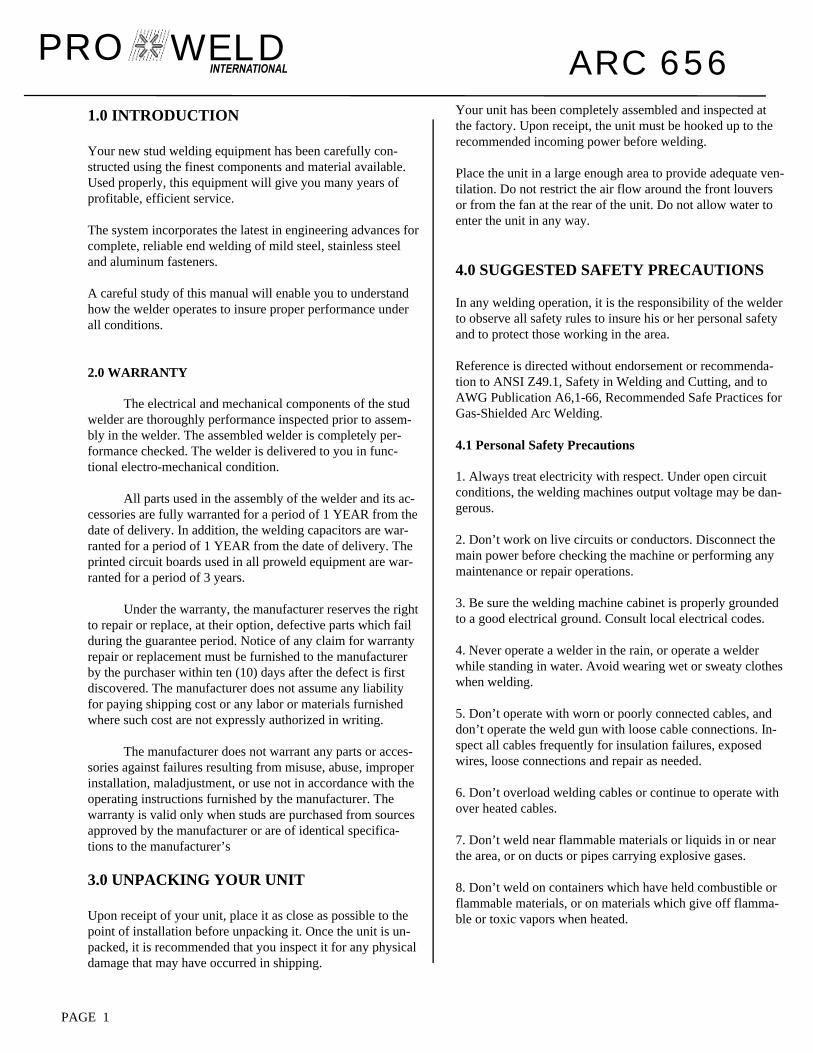
9.2 Weld Test and Inspection
Testing of weld quality beyond visual inspection varies with stud characteristics.
Refer to AWS (American Welding Society) Structure Welding code AWS D.1Rev. 1-76.
Welding procedures are covered in Sections 4.28 and 4.29.
Weld test and inspection is covered in Section 4.30, para-graphs 1 through 4. (American Welding Society, inc., 2501 N.W. 7th. Street, Miami, Fla. 33125)
When it does become necessary to adjust lift, you do so by removing the rear cap from the gun. This will expose the rear coil yoke assembly, the set screw and the lift adjusting screw (Loosen the set screw to avoid damaging the threads of the lift adjusting screw).
To increase lift: turn the lift adjusting screw out (counter clock-wise).
To decrease lift: turn the lift adjusting screw in (clockwise).
Once the lift has been set, tighten the set screw and replace the rear cap.
9.0 SETTING UP THE POWER SOURCE
9.1 Connections and settings.
CAUTION
Turn the power off before making connections
a) Connect the male end of the GROUND CABLE to the posi-tive GROUND terminal of the power supply, and secure the “C” clamp to the base plate. Make sure both connections are tight and the base metal is free of heavy paint or rust at the ground connection points.
b) Connect the male end of the WELD CABLE LEAD ON THE GUN to the negative GUN terminal of the power sup-ply.
c) Plug in the control cable portion on the gun into the control cable receptacle in the front of the power supply.
d) Set the Time adjustment required for the particular stud size.
e) Turn on the power supply by turning the ON-OFF switch to “ON”.
GOOD STUD WELDA good full fillet
STUD HANG UPAdjust foot to
insure the stud iscentered in the
ferrule
COLD WELDIncrease weldcurrent and/or
weld time
HOT WELDReduce weldcurrent and/or
weld time
FIGURE 5 WELD INSPECTION
PAGE 5

ARC 656 PRO WELD
A. Bend Test
Repeatedly bend the stud away from its axis until failure occurs.
B. Torque Test - Threaded Studs
Twist the stud to point of failure. Apply a twisting tensile load by using a collar, washer and nut.
C. Test Results
In an acceptable weld, failure will occur in the stud material or tear out of a thin base plate. Failure in the weld requires adjust-ment of procedure, weld time, weld current, or gun setup.
10.0 MAINTENANCE
CAUTION
Electric Shock Can Kill:
• Do not touch live electrical parts.
• Shut down welding power source, and disconnect input power before inspecting, maintaining, or servicing.
Lockout/tagging procedures consist of padlocking line discon-nect switch in the open position, removing fuses from fuse box, or shutting off and red-tagging circuit breaker or other discon-necting device.
MOVING PARTS can cause serious injury.
• Keep away from moving parts.
HOT SURFACES can cause severe burns.
• Allow cooling period before servicing.
FIGURE 6 FUSE BLOCK
PAGE 6
CAUTION
Read and follow the safety information at the beginning of this section before proceeding.
10.1 WELD CABLES
Every three months inspect cables for breaks in insulation. Repair or replace cables if insulation breaks are present. Clean and tighten connections at each inspection.
10.2 INTERNAL CLEANING
Every six months blow or vacuum dust and dirt from Thein-side of the welding power source. Remove the outer enclo-sure, and use a clean, dry airstream or vacuum suction for the cleaning operation. If dusty or dirty conditions are pres-ent, clean the unit monthly.
25 AMPSLO BLO
25 AMPSLO BLO
25 AMPSLO BLO
1 AMP
5 AMPCERAMIC
F5
F4
F3
F2
F1
1 AMP F6

ARC 656 PRO WELD
11.0 TROUBLE SHOOTING
Whenever possible, have a qualified electrician do the maintenance and trouble shooting work. Turn the input power off us-ing the disconnect switch at the fuse box before working inside the machine.
Trouble Possible Cause What To Do
Unit trips off without 1. Defective main SCR. 1. Check for defective SCR and welding. replace. 2. Defective sustaining arc SCR. 2. check and replace. 3. Defective 600-0016 P.C.board 3. Replace. 4. Shorted control cables 4. Repair.
Low output. 1. Input fuse blown. Unit is single 1. Replace fuse, repair input line. phase. Check for reason for fault.2. 2. Incorrect primary jumper link 2. Check jumper links connection for proper voltage. 3. Defective 600-0016 P.C. board. 3. Replace.
Maximum output but 1. Defective 600-0016 P.C. board. 1. Replace. no control.
Gun does not lift. 1. Blown 4 amp fuse. 1. Check and replace fuse. 2. Defective 600-0016 P.C. board. 2. Replace. 3. Defective control cable or 3. Repair short in cable, replace gun coil. gun coil. 6. Blown 1 amp fuse 6. Check and replace fuse
Gun lifts but does not 1. Blown 25 amp sustaining arc fuse. 1. Check and replace fuse. weld. 2. Defective sustaining arc SCR(s). 2. Replace bad part(s). 3. Defective 600-0016 P.C. board. 3. Replace. 4. Defective sustaining arc . 4. Check and Replace. resister. 5. Open weld cable or bad weld 5. Check and Repair. ground connection.
Gun lifts but does not 1. Defective 600-0016 P.C. board. 1. Replace. Plunge. 2. Defective time potentiometer. 2. Replace.
PAGE 7
ARC 656 PRO WELD
PAGE 8
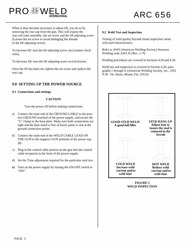
12.0 PARTS LIST
ITEM DESCRIPTION PART NUMBER
1 On-Off Switch 104-0035 1 Switch Faceplate 104-0036 1 Switch Knob 104-0037 2 Knob 102-0060 2 Timer potentiometer 111-0021 3 Digital Meter 103-0004 4 Green LED 108-0029 5 Red LED 108-0028 6 Female Camlok 107-0002 7 P/M R&S Connector 107-0001 8 Handle 102-0129 9 Handle Ends 102-0130 10 Top Cover 101-0032-2 11 Base 101-0032-1 12 Decal 122-0036
FIGURE 7 ARC-656
9
8
5
12
6
7
3
1
10
2
4
11

ARC 656 PRO WELD
FIGURE 8 INSIDE VIEW
PAGE 9
ITEM DESCRIPTION PART NUMBER
1 Fan 102-0131 2 Capacitor 106-0024 3 6 Position Fuse Strip 104-0038 1 Amp Fuse 120-0001 5 Amp Ceramic Fuse 120-0005 25 Amp Ceramic Fuse 120-0025 4 Support Arc Resistor 112-0004 5 Support Arc SCR (3) 108-0042 6 PCB Guide 102-0135 7 Weld SCR 108-0059 8 PCB 600-0016 9 Transformer 105-0028 10 On/Off Switch 104-0035
1
9
10
7
5
4
3
2
6
8

ARC 656 PRO WELD
FIGURE 9 WELD CONTROL P.C. BOARD
P/N 600-0016
+
+
+
++
+
+
+
D11
D27
D8
D14
D15
D16
D23 D
25
D24 D
26
D13
D28
D9
D22
D19
D18
D21
D20
ZD4
ZD5
ZD1
R43
R41
R9
R10
R18
R17
R48
R54
R35
R49
R47
R40
R52
R16
R39
R44
R20
R26
R11
R32
R29
R1
R35
R34
R19
R2
R5
R23
R33
R14
C1
C3
C7
C4
C5
C13
C6
C11
C2
C9
C13
V3
V5
V4
V6
V7
V9
Q1
V2
V8
IC1
IC3IC
4
IC2
OP
T5
OP
T7
OP
T6
OP
T1
OPT4
OP
T2
VR2
V10
R13
V1
TR1
R38
R8ZD
2
D2
D1
D3
D4
R7
D29
D30
D31
D17
R12
R51
R50
R45
R46
D6
D7
D12
VR1
R42
R36R37
R31
D5
OP
T3
C8
R30
ZD3
R28
R21
R27 R24
R22 R3
D10 R
4
R6
R15 R55
R56
+C
10
PAGE 10

WELD PRO MANUFACTURED BY
MADE IN THE U.S.A.