Embed Size (px)
Citation preview

Operation Manual
Rotary vane vacuum pump (oil-lubricated)
Type 063.3 - IE2 Type 0100.3 - IE2
Please read and pay attention
Albert Fezer Maschinenfabrik GmbH Hauptstraße 37 – 39 D-73730 Esslingen) Tel: (0711) 3 60 09 – 0 Fax (07 11) 3 60 09-40
e-mail: info @ fezer.com
Internet: www.fezer.com BA-Nr: 6.54.2.0077
VP-063.3-Europe-IE2 VP-063.3-Multi-IE2 VP-063.3-Brazil-IE2
VP-0100.3-Europe-IE2 VP-0100.3-Multi-IE2 VP-0100.3-Brazil-IE2

Operation Manual for Oil lubricated - rotary vane vacuum pumps __________________________________________________________________________
__________________________________________________________________________________________________
OM 063.3 – 0100.3-IE2, Issue 05/2015 page 2/27
Table of Contents Preface …………………………………………………….…………...…..3 Technical Data ………………………………………….…………...…….3 Product Description …………………………………………………...…4 Use ………………………………………….……………………...………..4 Principle of Operation …………………………...………………….……...4 Oil Circulation ………………………………..………………..…………….5 Cooling ……………………………….……………………………..…........5
Start Controls ………………………………………………………….........5 Safety ……………………………………………………………..……...…5 Intended Use …………………………………………………………….....5 Safety Notes ………………………………………………………..……....5 Emission of Oil Mist ……………………………………………………..….6 Noise Emission …………………………………………………….………6 Transport …………………………………………………………..………6 Transport in Packaging ……………………………………………………6 Transport without Packaging ……………………………………….……..6 Storage ………………………………………………………………..……6
Short-term Storage …………………………………………………….…..6 Conservation …………………………………………………………….…6 Installation and Commissioning ………………………………….……7
Installation Prerequisites ……………………………………………….….7 Mounting Position and Space ………………………………………….....7 Suction Connection ……………………………………………..………....7
Gas Discharge ………………………………………………..…………....8 Electrical Connection / Controls ……………………………………….....8
Installation …………………………………………………...……….……..8 Mounting ……………………………………………………………………8 Connecting Electrically …………………………………………...........….8
Connection Scheme Three-Phase Motor…………………………….9 Connecting Lines/Pipes ……………………………………..……………9 Filling Oil …………………………………………………..…………….….9 Recording of Operational Parameters.……………………..……...……10
Operation Notes ………………………………………..…………………10 Use ………………………………………………..……………………....10 Oil Return …………………………………………………..…………......11 Conveying Condensable Vapours ………………………………...……11
Maintenance ……………………………………………………………...11 Maintenance Schedule …………………………………………….….….11
Daily :…………………………………………………………………..11 Weekly : ……………………………………………………………….11
Monthly :…………………………………………………………...…..11 Every 6 Months :…………………………………………………..….11 Every Year :………………………………………………………..….11 Every 500 - 2000 Operating Hours : ……………………………..…11
Checking the Oil …………………………………………………………..12 Checking the Level ……………………………………………...……….12 Topping up Oil …………………………………………………………....12 Checking the Colour of the Oil ……………………………………….…12
Oil Life ……………………………………………………………….…….12 Oil and Oil Filter Change ………………………………………………....13 Draining Used Oil ………………………………………………………...13 Flushing the Vacuum Pump …………………………………………….13 Checking the Float Valve …….………………………………………….13
Replacing the Oil Filter …………………………………………………..13 Filling in Fresh Oil ………………………………………………………..14
Exhaust Filters …………………………………..…...…………….....14 Checks during Operation………..……….…………………………..14 Assessment ……………………………………………….………....14 Change of the Exhaust Filters …………………………..………….14
Removing the Exhaust Filters ……………………….………….14 Inserting the Exhaust Filters …………………………….………15
Overhaul ……………....………………………………………..….…15 Removal from Service ……………………………………………...15 Temporary Removal from Service ………………………………….15 Recommissioning …….......................................................................15
Dismantling and Disposal .……………………………………...…....16 Troubleshooting ..............................................................................17 Exploded View …..............................................................................22 Spare Parts .......................................................................................23 Spare Parts Kits................................................................................24 Accessories ......................................................................................24
Oil …………………………………………………………….…..........26
EC-Declaration of Conformity………………………………..……27

Operation Manual for Oil lubricated - rotary vane vacuum pumps
__________________________________________________________________________________________________
OM 063.3 – 0100.3-IE2, Issue 05/2015 page 3/27
Preface Congratulations on your purchase of the Fezer vacuum pump. With watchful observation of the field's requirements, innovation and steady development Fezer delivers modern vacuum and pressure solutions worldwide. These operating instructions contain information for
product description,
safety,
transport,
storage,
installation and commissioning,
maintenance,
overhaul,
troubleshooting and
spare parts
of the vacuum pump. For the purpose of these instructions, "handling" the vacuum pump means the transport, storage, installation, commissioning, influence on operating conditions, maintenance, troubleshooting and overhaul of the vacuum pump. Prior to handling the vacuum pump these operating instructions shall be read and understood. If anything remains to be clarified please contact your Fezer representative!
Keep these operating instructions and, if applicable, other pertinent operating instructions available on site.
Technical Data 063.3-IE2 Europe Multi Brazil
Suction capacity [m3/h] 63 63 76 76
Suction capacity [l/s] 17,50 17,50 21,11 21,11
Vacuum [mbar] -995 -995 -995 -995
Motor nominal rating [kW] 1,5 2,0 2,4 2,4
Motor nominal speedl [min-1] 1425 1450 1740 1740
Frequency [Hz] 50 50 60 60
Voltage [V] 230±10% 400±10% 190-208 380-415 220-230 440-460 220 380
Current consumption [A] 6,3 3,7 9,4 4,7 9,4 4,7 9,9 5,7
Noise level [db (A)] 64 64 66 66
Protective system IP55 IP55 IP55 IP55
Efficiency class IE2 IE2 IE2 IE2
Weight [kgs] 52 52 52 52
Öil quantity [l] 2 2 2 2
Water vapour tolerance max.
[hPa (=mbar)] 40 40 40 40
Water vapour capacity [l/h] 1,8 1,8 1,8 1,8
Operating temperature [°C] 84 84 92 92
Ambient temperature range [°C] see „Öil“
Ambient pressure Atmospheric pressure
0100.3-IE2 Europe Multi Brazil
Suction capacity [m3/h] 100 100 120 120
Suction capacity [l/s] 27,78 27,78 33,33 33,33
Vacuum [mbar] -995 -995 -995 -995
Motor nominal rating [kW] 2,2 2,7 3,4 3,4
Motor nominal speedl [min-1] 1445 1450 1740 1730
Frequency [Hz] 50 50 60 60
Voltage [V] 230±10% 400±10% 190-208 380-415 220-230 440-460 220 380
Current consumption [A] 8,5 4,9 11,8 5,9 12,4 6,2 12,8 7,4
Noise level [db (A)] 65 65 68 68
Protective system IP55 IP55 IP55 IP55
Efficiency class IE2 IE2 IE2 IE2
Weight [kgs] 70 70 70 70
Öil quantity [l] 2 2 2 22
Water vapour tolerance max.
[hPa (=mbar)] 40 40 40 40
Water vapour capacity [l/h] 2,8 2,8 2,8 2,8
Operating temperature [°C] 84 84 93 93
Ambient temperature range [°C] Siehe „Öl“
Ambient pressure Atmosphärendruck

Operation Manual for Oil lubricated - rotary vane vacuum pumps __________________________________________________________________________
__________________________________________________________________________________________________
OM 063.3 – 0100.3-IE2, Issue 05/2015 page 4/27
P r o d u c t D e s c r i p t i o n Use The vacuum pump is intended for
the suction of
air and other dry, non-aggressive, non-toxic and non-explosive gases
Conveying media with a lower or higher density than air leads to an increased thermal and/or mechanical Ioad an the vacuum pump and is permissible only after prior consultation with Fezer.
Permissible temperature range of the inlet gas: see "Oil", "Ambient temperature range"
In case the vacuum pump is equipped with a gas ballast (optional) water vapour within the gas flow can be tolerated within certain limits ( - > page 11: Conveying Condensable Vapours). The conveyance of other vapours shall be agreed upon with Fezer.
The vacuum pump is intended for the placement in a non-potentially explosive environment.
Version with float valve (j, 200) and oil return line:
The vacuum pump is thermally suitable for continuous operation (100 percent duty).
The vacuum pump is ultimate pressure proof.
Principle of Operation The vacuum pump works on the rotating vane principle.
A circular rotor (s, 14) is positioned centrically on the shaft of the vacuum pump. The shaft of the vacuum pump is driven by the drive motor shaft by means of a flexible coupling (310).
The rotor (s, 14) rotates in an also circular, fixed cylinder (t, 1), the centreline of which is offset from the centreline of the rotor such that the rotor and the inner wall of the cylinder almost touch along a line. Vanes (r, 22), sliding in slots in the rotor, separate the space between the rotor and the cylinder into chambers. At any time gas is sucked in and at almost any time ejected. Therefore the vacuum pump works almost pulsation free.
In order to avoid the suction of solids, the vacuum pump is equipped with a screen (261) in the suction connection.
In order to avoid reverse rotation after switching off, the vacuum pump is equipped with a non-return valve (257).

Operation Manual for Oil lubricated - rotary vane vacuum pumps __________________________________________________________________________
__________________________________________________________________________________________________
OM 063.3 – 0100.3-IE2, Issue 05/2015 page 5/27
Note: This valve shall not be used as a non-return valve or shut-off valve to the vacuum system and is no reliable means to prevent suction of oil into the vacuum system while the vacuum pump is shut down.
In case the vacuum pump is equipped with a gas ballast (optional):
Through the gas ballast (440) a small amount of ambient air is sucked into the pump chamber and compressed together with the process gas. This counteracts the accumulation of condensates from the process gas inside the vacuum pump ( - > page 11: Conveying Condensable Vapours).
The gas ballast line is equipped with a sinter metal filter.
Gas ballast version with ball valve:
The gas ballast line can be closed partially or completely by means of a ball valve.
In order to improve the operating characteristics the outlet of the pump chamber is equipped with a spring loaded valve (q, 159).
Oil Circulation The vacuum pump requires oil to seal the gaps, to lubricate the vanes (r, 22) and to carry away compression heat.
The oil reservoir is located on the pressure side of the vacuum pump (i.e. high pressure) at the bottom of the bottom chamber of the oil separator (n, 75).
The feed openings are located on the suction side of the vacuum pump (i.e. low pressure).
Forced by the pressure difference between pressure side and suction side oil is being drawn from the oil separator (n, 75) through the oil supply lines (210) and injected on the suction side.
Together with the sucked gas the injected oil gets conveyed through the vacuum pump and ejected into the oil separator (n, 75) as oil mist. Oil that separates before the exhaust filtern (o, 120) accumulates at the bottom of the bottom chamber of the oil separator (n, 75).
Oil that is separated by the exhaust filters (o, 120) accumulates at the bottom of the upper chamber of the oil separator (n, 75).
The flow resistance of the exhaust filtern (o, 120) causes the inside of the exhaust filtern (which is connected to the bottom chamber of the oil separator) to be on a higher pressure level than the outside of the exhaust filtern (i.e. the upper chamber of the oil separator). Because of the higher pressure in the bottom chamber it is not possible to let oil that drips off the exhaust filtern simply flow down to the bottom chamber.
Version with float valve and oil return line to the suction connection (j, 200):
Therefore the oil that accumulates in the upper chamber is sucked through the float valve (j, 200) and the oil return line (j, 195) to the suction connection (250).
Cooling
The vacuum pump is cooled by
radiation of heat from the surface of the vacuum pump Incl. oil separator (n, 75)
the air flow from the fan wheel of the drive motor (400) .
the process gas
the air flow from the fan wheel (f, 321) on the shaft of the vacuum pump
Start Controls The vacuum pump comes without start controls. The control of the vacuum pump is to be provided in the course of installation.
Safety
Intended Use Definition: For the purpose of these instructions, "handling" the vacuum pump means the transport, storage, installation, commission-ing, influence on operating conditions, maintenance, troubleshooting and overhaul of the vacuum pump.
The vacuum pump is intended for industrial use. It.shall be handled only by qualified personnel.
The allowed media and operational Iimits (-> page 4: Product Description) and the Installation prerequisites (-> page 7: Installation Prerequisites) of the vacuum pump shall be observed both by the manufacturer of the machinery into which the vacuum pump is to be incorporated and by the operator.
The maintenance instructions shall be observed.
Prior to handling the vacuum pump these Installation and operating instructions shall be read and understood. If anything remains to be clarified please contact your Fezer representative!
Safety Notes
The vacuum pump has been designed and manufactured according to state-of-the-art methods. Nevertheless, residual risks may remain. These operating instructions highlight potential hazards where appro-priate. Safety notes are tagged with one of the keywords DANGER, WARNING and CAUTION as follows:
DANGER
Disregard of this safety note will always lead to accidents with fatal or serious injuries.
WARNING
Disregard of this safety note may lead to accidents with fatal or serious injuries.
CAUTION
Disregard of this safety note may lead to accidents with minor injuries or property damalte.
Operation Manual for Oil lubricated - rotary vane vacuum pumps _____________________________________________________________________________
__________________________________________________________________________________________________
OM 063.3 – 0100.3-IE2, Issue 05/2015 page 6/27
Emission of OiI Mist The oil in the process gas is separated to the greatest possible extent, but not perfectly.
CAUTION
The non-OEM spares market offers exhaust filtern that are geometrically compatible with Fezer-vacuum pumps, but do not feature the high retention capacity of genuine Fezer-exhaust filters.
Increased risk of damage to health.
In order to keep the emission on the lowest possible level only genuine Fezer-exhaust filters shall be used.
The oil in the progress gas is separated to the greatest possible extent, but not perfectly.
CAUTION
The gas conveyed by the vacuum pump contains remainders of oil.
Aspiration of process gas over extended periods can be harmful.
The room into which the process gas is discharged must be sufficiently vented.
Note: The possibly sensible smell is not caused by droplets of oil, though, but either by gaseous process components or by readily vola-tile and thus gaseous components of the oil (particularly additives).
Noise Emission For the sound pressure level in free field according to EN ISO 2151 -> page 3: Technical Data.
Transport Note: Also a vacuum pump, that is not topped up with oil contains res-idues of oil (from the test run). Always transport and Store the vacuum pump in upright position. Do not put the vacuum pump on its side nor put it upside down.
Transport in Packaging
Packed on a pallet the vacuum pump is to be transported with a forklift.
Transport without Packaging
In case the vacuum pump is packed in a cardboard box with inflated cushions:
Remove the inflated cushions from the box
In case the vacuum pump is in a cardboard box cushioned with rolled corrugated cardboard:
Remove the corrugated cardboard from the box
In case the vacuum pump is laid in foam:
Remove the foam
In case the vacuum pump is bolted to a pallet or a base plate:
Remove the bolting between the vacuum pump and the pallet/base plate
In case the vacuum pump is fastened to the pallet by means of tightening straps:
Remove the tightening straps
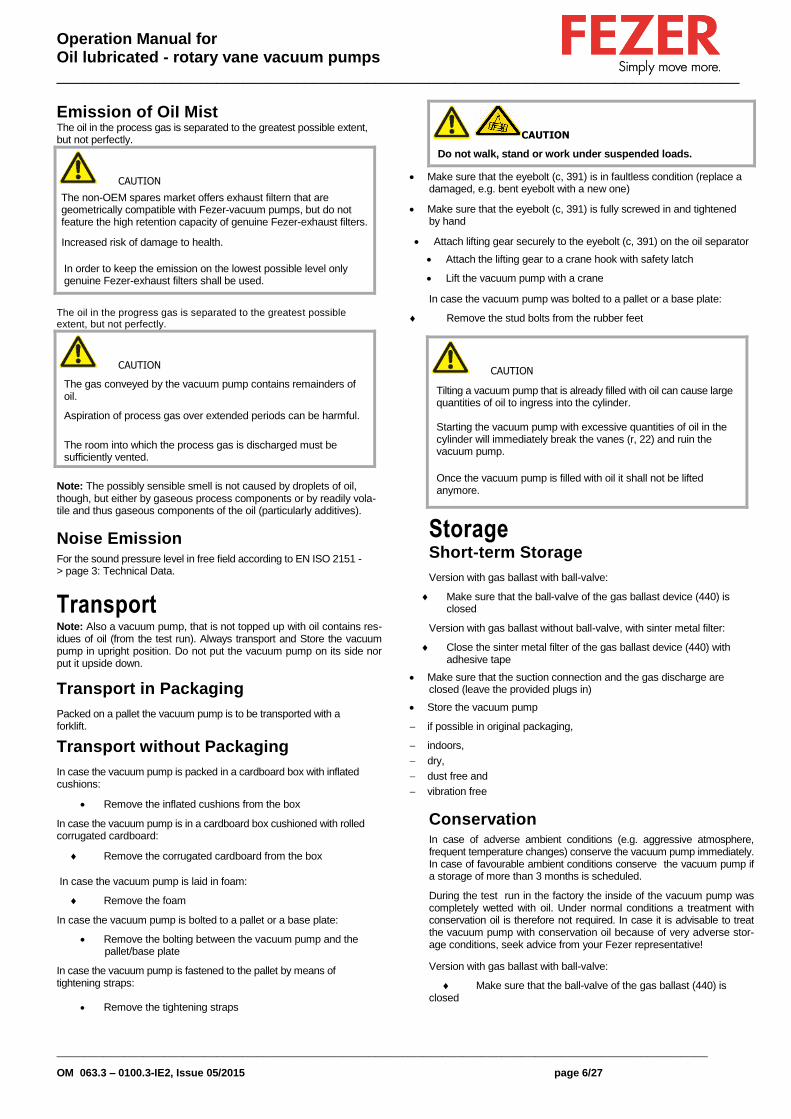
CAUTION
Do not walk, stand or work under suspended loads.
Make sure that the eyebolt (c, 391) is in faultless condition (replace a damaged, e.g. bent eyebolt with a new one)
Make sure that the eyebolt (c, 391) is fully screwed in and tightened by hand
Attach lifting gear securely to the eyebolt (c, 391) on the oil separator
Attach the lifting gear to a crane hook with safety latch
Lift the vacuum pump with a crane
In case the vacuum pump was bolted to a pallet or a base plate:
Remove the stud bolts from the rubber feet
CAUTION
Tilting a vacuum pump that is already filled with oil can cause large quantities of oil to ingress into the cylinder.
Starting the vacuum pump with excessive quantities of oil in the cylinder will immediately break the vanes (r, 22) and ruin the vacuum pump.
Once the vacuum pump is filled with oil it shall not be lifted anymore.
Prior to every transport make sure that the oil is drained
Storage Short-term Storage
Version with gas ballast with ball-valve:
Make sure that the ball-valve of the gas ballast device (440) is closed
Version with gas ballast without ball-valve, with sinter metal filter:
Close the sinter metal filter of the gas ballast device (440) with adhesive tape
Make sure that the suction connection and the gas discharge are closed (leave the provided plugs in)
Store the vacuum pump
if possible in original packaging,
indoors,
dry,
dust free and
vibration free
Conservation In case of adverse ambient conditions (e.g. aggressive atmosphere, frequent temperature changes) conserve the vacuum pump immediately. In case of favourable ambient conditions conserve the vacuum pump if a storage of more than 3 months is scheduled.
During the test run in the factory the inside of the vacuum pump was completely wetted with oil. Under normal conditions a treatment with conservation oil is therefore not required. In case it is advisable to treat the vacuum pump with conservation oil because of very adverse stor-age conditions, seek advice from your Fezer representative!
Version with gas ballast with ball-valve:
Make sure that the ball-valve of the gas ballast (440) is closed

Operation Manual for Oil lubricated - rotary vane vacuum pumps _____________________________________________________________________________
__________________________________________________________________________________________________
OM 063.3 – 0100.3-IE2, Issue 05/2015 page 7/27
Version with gas ballast without ball-valve, with sinter metal filter:
Close the sinter metal filter of the gas ballast (440) with adhesive tape
Make sure that all ports are firmly closed; seal all ports that are not sealed with PTFE-tape, gaskets or o-rings with adhesive tape
Note: VCI stands for "volatile corrosion inhibitor". VCI-products (film, paper, cardboard, foam) evaporate a substance that condenses in molecular thickness on the packed good and by its electro-chemical properties effectively suppresses corrosion on metallic surfaces. However, VCI-products may attack the surfaces of plastics and elastomers. Seek advice from your loca.l packaging dealer! Fezer uses CORTEC VCI 126 R film for the overseas packaging of large equipment
Wrap the vacuum pump in VCI film
Store the vacuum pump
if possible in original packing,
indoors,
dry,
dust free and
vibration free.
For Commissioning after conservation:
Make sure that all remains of adhesive tape are removed from the ports
Commission the vacuum pump as described in the chapter Installation and Commissioning ( - > page 7).
Installation and Commissioning Installation Prerequisites
CAUTION
In case of non-compliance with the installation prerequisites, particularly in case of insuffiient cooling:
Risk of damalte or destruction of the vacuum pump and adjoining plant components!
Risk of injury!
The installation prerequisites must be complied with.
Make sure that the integration of the vacuum pump is carried out such that the essential safety requirements of the Machine Directive 2006/42/EC are complied with (in the responsibility of the designer of the machinery into which the vacuum pump is to be incorporated; -> page 27: note in the EC-Declaration of Conformity)
Mounting Position and Space
Make sure that the environment of the vacuum pump is not potentially explosive
Make sure that the following ambient conditions will be complied with:
ambient temperature: see "Oil"
If the vacuum pump is installed in a colder environment than allowed with the oil used:
Fit the vacuum pump either with an oil sump heating (on request)
or fit the vacuum pump with a temperature switch and control the vacuum pump such that it will start automatica.lly when the oil sump temperature falls below the allowed temperature
ambient pressure: atmospheric
Make sure that the environmental conditions comply with the protection cass of the drive motor (according to the nameplate)
Make sure that the vacuum pump will be placed or mounted horizontally
Make sure that in order to warrant a sufficient cooling there will be a clearance of minimum 20 cm between the vacuum pump and nearby walls
Make sure that no heat sensitive parts (plastics, wood, cardboard, paper, electronics) will touch the surface of the vacuum pump
Make sure that the installation space or location is vented such that a sufficient cooling of the vacuum pump is warranted
CAUTION
During operation the surface of the vacuum pump may reach tem-peratures of more than 70 °C.
Risk of burns!
Make sure that the vacuum pump will not be touched inadvertently during operation, provide a guard if appropriate
Make sure that the sight glass (l, 83) will remain easily accessible
If the oil change is meant to be performed on location:
Make sure that the drain port (m, 95), the oil filter (g, 100) and the filling port (k, 88) will remain easily accessible
Make sure that enough space will remain for the removal and the reinsertion of the exhaust filters(o, 120)
Suction Connection
CAUTION
Intruding foreign objects or liquids can destroy the vacuum pump.
In case the inlet gas can contain dust or other foreign solid particles:
Make sure that a suitable filter (5 micron or less) is installed upstream the vacuum pump
Make sure that the suction line f i t to the suction connection (e, 260) of the vacuum pump
Make sure that the gas will be sucked through a vacuum-tight flexible hose or a pipe
In case of using a pipe:
Make sure that the pipe will cause no stress on the vacuum pump's connection, if necessary use an expansion joint
Make sure that the line size of the suction line over the entire length is at least as large as the suction connection (e, 260) of the vacuum pump
In case of very long suction lines it is prudent to use !arger line sizes in order to avoid a loss of efficiency. Seek advice from your Fezer representative!
If two or more vacuum pumps work on the same suction line, if the volume of the vacuum system is large enough to suck back oil or if the vacuum shall be maintained after switching off the vacuum pump:
Provide a manual or automatic operated valve (= non-return valve) in the suction line
(The standard non-return valve that is installed inside the suction con-nection is not meant to be used for this purpose!)
If the vacuum pump is planned to be used for the suction of gas that contains limited quantities of condensable vapour:
Provide a shut-off valve, a drip-leg and a drain cock in the suction line, so that condensates can be drained from the suction line

Operation Manual for Oil lubricated - rotary vane vacuum pumps _____________________________________________________________________________
__________________________________________________________________________________________________
OM 063.3 – 0100.3-IE2, Issue 05/2015 page 8/27
Make sure that the suction line does not contain foreign objects, e.g. welding scales
Gas Discharge
The discharged gas must flow without obstruction. It is not permitted to shut off or throttle the discharge line or to use it at as a pressurised air source.
The following guidelines for the discharge line do not apply, if the aspirated air is discharged to the environment right at the vacuum pump.
CAUTION
The discharged gas contains small quantities of vacuum oil.
Staying in vacuum oil contaminated air bears a risk of damage to health.
If air is discharged into rooms where persons stay, sufficient ventila-
tion must be provided for.
Make sure that the discharge line f i t to the gas discharge (d, 155) of the vacuum pump
In case of using a pipe:
Make sure that the pipe will cause no stress on the vacuum pump's connection, if necessary use an expansion joint
Make sure that the line size of the discharge line over the entire length is at least as large as the gas discharge (d, 155) of the vacuum pump
In case the length of the discharge line exceeds 2 m it is prudent to use larger line sizes in order to avoid a loss of efficiency and an overload of the vacuum pump. Seek advice from your Fezer representative!
With unrestricted suction the counter pressure at the gas discharge (d, 155) of the vacuum pump must not exceed 1.3 bar abs (in rase of doubt to be verified during commissioning at a suitable time).
Make sure that the discharge line either slopes away from the vacuum pump or provide a liquid separator or a drip leg with a drain cock, so that no liquids can back up into the vacuum pump
WARNING Discharge lines made from non-conductive material can build up static charge. Static discharge can cause explosion of potentially existing oil mist.
The discharge line must be made of conductive material or provisions must be made against static discharge.
Electrical Connection / Controls
Make sure that the stipulations acc. to the EMC-Directive 2004/108/EC and Low-Voltage-Directive 2006/95/EC as well as the EN-standards, electrical and occupational safety directives and the loca.l or national regulations, respectively, are complied with (this is in the responsibility of the designer of the machinery into which the vacuum pump is to be incorporated; -> page 27: note in the EC-Declaration of Conformity).
Make sure that the power supply for the drive motor is compatible with the data on the nameplate of the drive motor (400)
Make sure that an overload protection according to EN 60204-1 is provided for the drive motor
Make sure that the drive of the vacuum pump will not be affected by electric or electromagnetic disturbance from the mains; if necessary seek advice from the Fezer service
In case of mobile installation:
Provide the electrical connection with grommets that serve as strain-relief
Installation Mounting
Make sure that the Installation Prerequisites ( - > page 7) are complied with
Set down or mount the vacuum pump at i t s location
Connecting Electrically
WARNING
Risk of electrical shock, risk of damalte to equipment.
Electrical Installation work must only be executed by qualified per-sonnel that knows and observes the following regulations:
- IEC 364 or CENELEC HD 384 or DIN VDE 0100, respectively,
- IEC-Report 664 or DIN VDE 0110,
-BGV A2 (VBG 4) or corresponding national accident prevention regulation.
CAUTION
The connection schemes given below are typical. Depending on the specific order or for certain market deviating connection schemes may apply.
Risk of damage to the drive motor!
The inside of the terminal box shall be checked for drive motor
connection instructions/schemes.
Electrically connect the drive motor (400)
Connect the protective earth conductor

Operation Manual for Oil lubricated - rotary vane vacuum pumps _____________________________________________________________________________
__________________________________________________________________________________________________
OM 063.3 – 0100.3-IE2, Issue 05/2015 page 9/27
Connection Scheme Three-Phase Motor
Delta connection (low voltage):
CAUTION
Operation in the wrong direction of rotation can destroy the vacuum pump in short time.
Prior to starting-up it must be made sure that the vacuum pump is operated in the proper direction.
Version with three-phase motor:
Determine the intended direction of rotation with the arrow (a, 431) (stuck on or cast)
"Bump" the drive motor (400)
Watch the fan wheel of the drive motor (400) and determine the direction of rotation just before the fan wheel stops
If the rotation must be changed:
Switch any two of the drive motor wires (three-phase motor)
Connecting Lines/Pipes
In case the suction line is equipped with a shut-off valve:
Connect the suction line
Connect the discharge line
Installation without discharge line:
Make sure that the gas discharge (d, 155) is open
Make sure that all provided covers, guards, hoods etc. are mounted
Make sure that cooling air inlets and outlets are not covered or ob-structed and that the cooling air flow is not affected adversely in any other way
Filling Oil
In case the vacuum pump was treated with conservation oil:
Drain the remainders of conservation oil
CAUTION
The vacuum pump is shipped without oil.
Operation without oil will ruin the vacuum pump in short time.
Prior to commissioning it must be made positively sure that oil is filled in.
The vacuum pump is delivered without oil (oil specification -> page 26: Oil).
Keep approx. 2.0 litres oil acc. to the table Oil ( - > page 26)
ready
Note: The amount given in these operating instructions is a guide. The sight glass (l, 83) indicates the actual amount to be filled in.
CAUTION
Filling oil through the suction connection (e, 260) will result in breakage of the vanes (r, 22) and destruction of the vacuum pump.
Oil may be filled through the filling port (k, 88) only.
Star connection ( high voltage):
Double star connection, multi voltage motor with 9 terminals (low voltage):
star connection, multi voltage motor with 9 terminals (high voltage):
Operation Manual for Oil lubricated - rotary vane vacuum pumps _____________________________________________________________________________
__________________________________________________________________________________________________
OM 063.3 – 0100.3-IE2, Issue 05/2015 page 10/27
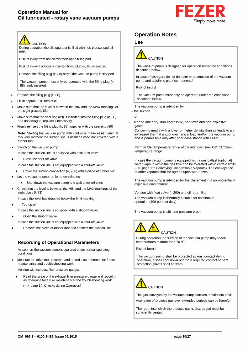
CAUTION During operation the oil separator is filled with hot, pressurised oil mist.
Risk of injury from hot oil mist with open filling port.
Risk of injury if a loosely inserted filling plug (k, 88) is ejected.
Remove the filling plug (k, 88) only if the vacuum pump is stopped.
The vacuum pump must only be operated with the filling plug (k, 88) firmly inserted.
Remove the filling plug (k, 88)
Fill in approx. 2.0 litres of oil
Make sure that the level is between the MIN and the MAX-markings of the sight glass (l, 83)
Make sure that the seal ring (89) is inserted into the filling plug (k, 88) and undamaged, replace if necessary
Firmly reinsert the filling plug (k, 88) together with the seal ring (89)
Note: Starting the vacuum pump with cold oil is made easier when at this very moment the suction line is neither closed nor covered with a rubber mat.
Switch on the vacuum pump
In case the suction line is equipped with a shut-off valve:
Close the shut-off valve
In case the suction line is not equipped with a shut-off valve:
Cover the suction connection (e, 260) with a piece of rubber mat
Let the vacuum pump run for a few minutes
Shut down the vacuum pump and wait a few minutes
Check that the level is between the MIN and the MAX-markings of the sight glass (l, 83)
In case the level has dropped below the MIN-marking:
Top-up oil
In case the suction line is equipped with a shut-off valve:
Open the shut-off valve
In case the suction line is not equipped with a shut-off valve:
Remove the piece of rubber mat and connect the suction line
Recording of Operational Parameters
As soon as the vacuum pump is operated under normal operating conditions:
Measure the drive motor current and record it as reference for future maintenance and troubleshooting work
Version with exhaust filter pressure gauge:
Read the scale of the exhaust filter pressure gauge and record it as reference for future maintenance and troubleshooting work
( - > page 14: Checks during Operation)
Operation Notes
Use
CAUTION
The vacuum pump is designed for operation under the conditions described below.
In case of disregard risk of damalte or destruction of the vacuum pump and adjoining plant components!
Risk of injury!
The vacuum pump must only be operated under the conditions described below.
The vacuum pump is intended for
the suction
of
air and other dry, non-aggressive, non-toxic and non-explosive gases
Conveying media with a lower or higher density than air leads to an increased thermal and/or mechanical load and/or the vacuum pump and is permissible only after prior consultation with Fezer.
Permissible temperature range of the inlet gas: see "Oil", "Ambient temperature range"
In case the vacuum pump is equipped with a gas ballast (optional) water vapour within the gas flow can be tolerated within certain limits ( - > page 11: Conveying Condensable Vapours). The conveyance of other vapours shall be agreed upon with Fezer.
The vacuum pump is intended for the placement in a non-potentially explosive environment.
Version with float valve (j, 200) and oil return line:
The vacuum pump is thermally suitable for continuous operation (100 percent duty).
The vacuum pump is ultimate pressure proof
CAUTION
During operation the surface of the vacuum pump may reach temperatures of more than 70 °C.
Risk of burns!
The vacuum pump shall be protected against contact during operation, it shall cool down prior to a required contact or heat protection gloves shall be worn.
CAUTION
The gas conveyed by the vacuum pump contains remainders of oil.
Aspiration of process gas over extended periods can be harmful.
The room into which the process gas is discharged must be sufficiently vented.

Operation Manual for Oil lubricated - rotary vane vacuum pumps _____________________________________________________________________________
__________________________________________________________________________________________________
OM 063.3 – 0100.3-IE2, Issue 05/2015 page 11/27
Make sure that all provided covers, guards, hoods etc. remain mounted
Make sure that protective devices will not be disabled
Make sure that cooling air inlets and outlets will not be covered or obstructed and that the cooling air flow will not be affected adversely in any other way
Make sure that the installation prerequisites ( - > page 7: Installation Prerequisites) are complied with and will remain complied with, particularly that a sufficient cooling will be ensured
Oil Return
Conveying Condensable Vapours
CAUTION
Residual condensates dilute the oil, deteriorate its lubricating properties and can cause a seizure of the rotor.
Apply a suitable operating method to make sure that no condensates remain in the vacuum pump.
In order to use the vacuum pump for the conveyance of condensable vapours, the vacuum pump must be equipped with a shut-off valve in the suction line and with a gas ballast.
Version with gas ballast with ball-valve:
Make sure that the gas ballast valve is open and will remain open during operation
Close the shut-off valve in the suction line
Operate the vacuum pump with the suction line shut off for approx. half an hour, so that the operating temperature rises to approx. 75 °C
At process start:
Open the shut-off valve in the suction line
At the process end:
Close the shut-off valve in the suction line
Operate the vacuum pump for another approx. half an hour
Maintenance
DANGER
In case the vacuum pump conveyed gas that was contaminated with foreign materials which are dangerous to health, harmful material can reside in filters.
Danger to health during inspection, cleaning or replacement of filters.
Danger to the environment.
Personal protective equipment must be worn during the handling of contaminated filters.
Contaminated filters are special waste and must be disposed
of separately in compliance with applicable regulations.
CAUTION
During operation the surface of the vacuum pump may reach temperatures of more than 70 °C.
Risk of burns!
Prior to action that requires touching of the vacuum pump, let the vacuum pump cool down, however, if the oil is to be drained, for
no more than 20 minutes (the oil shall still be warm when being drained)
Prior to disconnecting connections make sure that the connected pipes/lines are vented to atmospheric pressure
Maintenance Schedule
Note: The maintenance intervals depend very much on the individual operating conditions. The intervals given below shall be considered as starting values which should be shortened or extended as appropriate. Particularly heavy duty operation, such like high dust loads in the environment or in the process gas, other contaminations or ingress of process material, can make it necessary to shorten the maintenance intervals significantly. Daily:
Check the level and the colour of the oil ( - > page 12: Checking the Oil)
Weekly:
Check the vacuum pump for oil leaks - in case of leaks have the vacuum pump repaired (Fezer service)
Monthly:
Check the function of the exhaust filters (o, 120) ( - > page 14: Exhaust Filters)
Make sure that the vacuum pump is shut down and locked against inadvertent start up
In case an inlet air filter is installed:
Check the inlet air filter, if necessary replace
In case of operation in a dusty environment:
->under -> page 11: Every 6 months:
Every 6 Months:
Make sure that the housing is free from dust and dirt, clean if necessary
Make sure that the vacuum pump is shut down and locked against inadvertent start up
Clean the fan cowlings, fan wheels, the ventilation grilles and cooling fins
Every Year:
Make sure that the vacuum pump is shut down and locked against inadvertent start up
Replace the exhaust filters (o, 120) ( - > page 14: Exhaust Filters)
In case an inlet air filter is installed:
Replace the inlet air filter
Check the inlet screen (261), clean if necessary
Version with gas ballast (440) with sinter metal filter:
Clean the sinter metal filter
Every 500 - 2000 Operating Hours:
( - > page 11: Oil Life):
Change the oil and the oil filter (g, 100) ( - > page 13: Oil and Oil Filter Change)

Operation Manual for Oil lubricated - rotary vane vacuum pumps _____________________________________________________________________________
__________________________________________________________________________________________________
OM 063.3 – 0100.3-IE2, Issue 05/2015 page 12/27
Version with float valve (j, 200) and oil return line
Check the float valve (j, 200) ( - > page 13: Checking the Float Valve)
Checking the Oil Checking the Level
Make sure that the vacuum pump is shut down and the oil has collected at the bottom of the oil separator (n, 75)
Read the level on the sight glass (l, 83)
In case the level has dropped underneath the MIN-marking:
Top up oil ( - > page 12: Topping up Oil)
In case the level exceeds the MAX-marking:
Excessive dilution with condensates - change the oil and check the process
If appropriate retrofit a gas ballast (Fezer Service) and observe the chapter Conveying Condensable Vapours ( - > page 11)
In case the level exceeds the MAX-marking despite proper use of the gas ballast:
Clean the sinter metal filter (compressed air)
Topping up OiI
Note: Under normal conditions there should be no need to top up oil during the recommended oil change intervals. A significant level drop indicates a malfunction ( - > page 17: Troubleshooting).
Note: During operation the exhaust filters get saturated with oil. It is therefore normal that the oil level will drop slightly after replacement of the exhaust filters.
CAUTION
Filling oil through the suction connection (e, 260) will result in breakage of the vanes (r, 22) and destruction of the vacuum pump.
Oil may be filled through the filling port (k, 88) only.
CAUTION
During operation the oil separator is filled with hot, pressurised oil mist.
Risk of injury from hot oil mist with open filling port.
Risk of injury if a loosely inserted filling plug (k, 88) is ejected.
Remove the filling plug (k, 88) only if the vacuum pump is
stopped.
The vacuum pump must only be operated with the filling plug
(k, 188) firmly inserted.
Make sure that the vacuum pump is shut down and locked against inadvertent start up
Remove the filling plug (k, 88)
Top up oil until the level reaches the middle of the sight glass (l, 83)
Make sure that the seal ring (89) is inserted into the filling plug (k, 88) and undamaged, replace if necessary
Firmly reinsert the filling plug (k, 88) together with the seal ring (89)
Checking the Colour of the OiI Note: The oil should be light, either transparent, a little foamy or a little tarnished. A milky discolouration that does not vanish after sedation of the oil indicates contamination with foreign material. Oil that is either contaminated with foreign material or burnt must be changed ( - > page 13: Oil and Oil Filter Change). In case the oil appears to be contaminated with water or other conden-sates despite proper use of the gas ballast:
Clean the sinter metal filter (compressed air)
Oil Life The oil life depends very much on the operating conditions. A clean and dry air stream and operating temperatures below 100 °C are ideal. Under these conditions the oil and the oil filter (g, 100) shall be changed every 500 to 2000 operating hours or after half a year.
Under very unfavourable operating conditions the oil life can be less than 500 operating hours. Extremely short life times indicate malfunctions ( - > page 17: Troubleshooting) or unsuitable operating conditions, though.
Chosing a synthetic oil instead of a mineral oil can extend the oil life. To select the oil best suited oil for your process please contact your Fezer representative.
If there is no experience available with regard to the oil life under the prevailing operation conditions, it is recommended to have an oil analysis carried out every 500 operating hours and establish the change interval accordingly.

Operation Manual for Oil lubricated - rotary vane vacuum pumps _____________________________________________________________________________
__________________________________________________________________________________________________
OM 063.3 – 0100.3-IE2, Issue 05/2015 page 13/27
Oil and Oil Filter Change
DANGER
In case the vacuum pump conveyed gas that was contaminated with harmful foreign material the oil and the oil filter will be contaminated with harmful material.
Danger to health during the changing of contaminated oil and oil filtern.
Danger to the environment.
Wear personal protective equipment during the changing of contaminated oil and oil filters.
Contaminated oil and oil filtern are special waste and must be disposed of separately in compliance with applicable regulations.
Draining Used Oil
Note: After switching off the vacuum pump at normal operating tem-perature wait no more than 20 minutes before the oil is drained (the oil shall still be warm when being drained).
Make sure that the vacuum pump is shut down and locked against inadvertent start up
Make sure that the vacuum pump is vented to atmospheric pressure
• Put a drain tray underneath the drain port (m, 95)
•Remove the drain plug (m, 95) and drain the oil
When the oil stream dwindles:
Reinsert the drain plug (m, 95)
Switch the vacuum pump on for a few seconds
Make sure that the vacuum pump is shut down and locked against inadvertent start up
Remove the drain plug (m, 95) again and drain the remaining oil
Make sure that the seal ring (96) is inserted into the drain plug (m, 95) and undamaged, replace if necessary
Firmly reinsert the drain plug (m, 95) together with the seal ring (96)
Dispose of the used oil in compliance with applicable regulations
Flushing the Vacuum Pump
WARNING
Degraded oil can choke pipes and coolers.
Risk of damage to the vacuum pump due to insufficient lubrication.
Risk of explosion due to overheating.
If there is a suspicion that deposits have gathered inside the vacuum pump the vacuum pump shall be flushed.
Make sure that all the used oil is drained
Make sure that the used oil filter (g, 100) is still in place
Create 2.0 litres flushing agent from 50 percent oil and 50 percent paraffin or diesel fuel/fuel oil
Make sure that the drain plug (m, 95) is firmly inserted
Remove the filling plug (k, 88)
Fill in the flushing agent
Firmly reinsert the filling plug (k, 88)
Close the suction line
Run the vacuum pump for at least half an hour
Drain the flushing agent and dispose of it in compliance with appli-cable regulations
Note: Due to the use of paraffin and even more in rase of using diesel fuel/fuel oil, an unpleasant odour can occur after recommissioning. If this is a problem, diesel fuel/fuel oil should be avoided and the vacuum pump be run at idle in a suitable place until the unpleasant odour vanishes.
Checking the Float Valve
(Version with float valve and oil return line only)
Note: lt is essential that the float valve (j, 200) works properly, so that the vacuum pump will achieve the intended ultimate pressure and no oil will be expelled out of the gas discharge (d, 155).
Make sure that the vacuum pump is shut down and locked against inadvertent start up
Prior to disconnecting pipes/lines make sure that the connected pipes/lines are vented to atmospheric pressure
• Remove the discharge line, if necessary
• Remove the exhaust cover (d, 155) above the float valve (j, 200)
• Remove the oil from the floater chamber with the aid of a suction hose or a wash bottle
Undo the screws (341) and remove the fan cover (f, 340)
Note: While undoing the banjo fitting of the oil return line (j, 195) a small amount of oil will leak out: keep a cleaning rag ready. Be ca.reful not to lose the sealing rings of the banjo fitting.
Undo the banjo fitting of the oil return line (j, 195) from the oil separator (n, 75) and bend the oil return line a little bit aside
Undo the two screws of the flange of the float valve (j, 200) and pull the float valve out of the oil separator (n, 75)
Check the cleanliness and function of the float valve (j, 200), blow out with compressed air, if necessary
Make sure that the o-ring on the flange of the float valve (j, 200) is in place and undamaged, replace with a new o-ring, if necessary
Insert the float valve (j, 200) in the proper orientation into the oil separator (n, 75) and fasten it with two screws and lock washers
Connect the banjo fitting of the oil rturn line (j, 195) to the oil separator (n, 75) with the hollow-core screw and two seal rings
Fasten the fan cover (f, 340) to the vacuum pump with the screws (341)
Only if the exhaust filters (o, 120) are not meant to be changed, too:
Make sure that the seal (141) under the exhaust cover (d, 155) is clean and undamaged, if necessary replace with a new seal (141)
Mount the exhaust cover (d, 155) together with the seal (141), hex head screws (146) and lock washers on the oil separator (n, 75)
If necessary connect the discharge line
Replacing the Oil Filter
Make sure that the oil is drained
Remove the oil filter (g, 100)
Apply a drop of fresh oil on the seal ring of the new oil filter (g, 100)

Operation Manual for Oil lubricated - rotary vane vacuum pumps _____________________________________________________________________________
__________________________________________________________________________________________________
OM 063.3 – 0100.3-IE2, Issue 05/2015 page 14/27
Mount the new oil filter (g, 100) and tighten it by hand
Dispose of the used oil filter in compliance with applicable regulations
Filling in Fresh Oil
Keep 2.0 litres oil acc. to the table Oil ( - > page 26) ready
Note: The amount given in these operating instructions is a guide. The sight glass (l, 83) indicates the actual amount to be filled in.
Make sure that the drain plug (m, 95) is firmly inserted
CAUTION
Filling oil through the suction connection (e, 260) will result in breakage of the vanes (r, 22) and destruction of the vacuum pump.
Oil may be filled through the filling port (k, 88) only.
Remove the filling plug (k, 88)
Fill in approx. 2.0 litres of oil
Make sure that the level is between the MIN and the MAX-mark-ings of the sight glass (l, 83)
Make sure that the seal ring (89) is inserted into the filling plug (k, 88) and undamaged, replace if necessary
Firmly reinsert the filling plug (k, 88) together with the seal ring (89)
Exhaust Filters Checks during Operation
Fezer recommends the use of a filter pressure gauge (available as ac-cessory, -> page 24: Accessories). Without filter pressure gauge the fil-ter resistance shall be assessed on the basis of the drive motor current drawn.
Version with exhaust filter pressure gauge:
Remove the suction line from the suction connection (e, 260) (unrestricted suction!)
Make sure that the vacuum pump is running
Check that the reading on the filter pressure gauge is in the green field
Reconnect the suction line to the suction connection (e, 260)
Version without filter pressure gauge:
Make sure that the vacuum pump is running
Check that the drive motor current drawn is in the usual range
Assessment
If
the reading on the filter pressure gauge is in the red field,
or
the drive motor draws too much current and/or the pump flow rate has dropped,
then the exhaust filters (o, 120) are clogged and must be replaced.
Note: Exhaust filters cannot be cleaned successfully. Clogged exhaust filters must be replaced with new ones.
If
the filter pressure gauge indicates a lower pressure than usual,
or
the drive motor draws less current than usual,
then one exhaust filter (o, 120) is broken through, the exhaust filter
must be replaced.
If the discharged gas contains oil,
the exhaust filters (o, 120) can either be clogged or broken through and, if applicable, must be replaced.
Change of the Exhaust Filters
DANGER
In case the vacuum pump conveyed gas that was contaminated with harmful foreign material the exhaust filters will be contaminated with harmful material.
Danger to health during the changing of the contaminated exhaust filters.
Danger to the environment.
Wear personal protective equipment during the changing of the contaminated exhaust fiIters.
Used exhaust filters are special waste and must be disposed of separately in compliance with applicable regulations..
CAUTION
The filter springs (p, 125) can fly out of the exhaust port during re-moval or insertion.
Risk of eye injury.
Eye protection goggles must be worn while handling filter springs (p, 125).
Removing the Exhaust Filters
Make sure that the vacuum pump is shut down and locked against inadvertent start up
Prior to disconnecting pipes/lines make sure that the connected pipes/lines are vented to atmospheric pressure
• Remove the discharge line, if necessary
• Remove the exhaust covers (d, 155) from the oil separator (n, 75)
• Loosen the screws in the centre of the exhaust filter retaining
springs (p, 125), but do not remove them
Press the exhaust filter retaining springs (p, 125) out of the indents and rotate them
Remove the exhaust filter retaining springs (p, 125) from the oil separator (n, 75)
Pull the exhaust filtern (o, 120) out of the oil separator (n, 75)

Operation Manual for Oil lubricated - rotary vane vacuum pumps _____________________________________________________________________________
__________________________________________________________________________________________________
OM 063.3 – 0100.3-IE2, Issue 05/2015 page 15/27
Inserting the Exhaust Filters
CAUTION
The non-OEM spares market offers exhaust filters that are geometrically compatible with Fezer-vacuum pumps, but do not feature the high retention ca.pacity of genuine Fezer-exhaust filters and deteriorate the service life and the efficiency of the vacuum pump due to their increased back pressure.
Increased risk of damalte to health.
Adverse effect on efficiency and service life.
In order to keep the emission on the lowest possible level and to preserve efficiency and service life only genuine Fezer-exhaust filters shall be used.
Make sure that the new exhaust filtern (o, 120) are equipped with new o-rings
Insert the exhaust filters (o, 120) such that their ports are properly seated in their receptacles in the oil separator (n, 75)
Make sure that the tips of the screws in the centre of the exhaust filter retaining springs (p, 125) protrude the retaining springs by about 2 - 5 revolutions
Insert the exhaust filter retaining springs (p, 125) such that their ends are secured in their receptacles in the oil separator (n, 75) by the protrusions and that the tips of the screws snap into the indent of the exhaust filters (o, 120)
Tighten the screws in the exhaust filter retaining springs (p, 125) such that the screw heads touch the spring steel sheets
Make sure that the seals (141) under the exhaust covers (d, 155) are clean and undamaged, if necessary replace with new seals (141)
Mount the exhaust covers (d, 155) together with the seals (141), hex head screws (146) and lock washers on the oil separator (n, 75)
If necessary connect the discharge line
Note: During operation the exhaust filters get saturated with oil. It is therefore normal that the oil level will drop slightly after replacement of the exhaust filters.
Overhaul
CAUTION
In order to achieve best efficiency and a long life the vacuum pump was assembled and adjusted with precisely defined tolerances.
This adjustment will be lost during dismantling of the vacuum pump.
lt is therefore strictly recommended that any dismantling of the vacuum pump that is beyond of what is described in this manual shall be done by Fezer service.
DANGER
In case the vacuum pump conveyed gas that was contaminated with harmful foreign material the oil, the oil filter and the exhaust filter(s) will be contaminated with harmful material.
Harmful material can reside in pores, gaps and internal spaces of the vacuum pump.
Danger to health during dismantling of the vacuum pump.
Danger to the environment.
Prior to shipping the vacuum pump shall be decontaminated as good as possible and the contamination status shall be stated in a "Declaration of Contamination" (form available at Fezer).
Fezer Service will only accept pumps that come with a completely filled in and legally binding signed “Declaration of conformity” (form available at Fezer).
Removal from Service Temporary Removal from Service
Prior to disconnecting pipes/lines make sure that all pipes/lines are vented to atmospheric pressure
Recommissioning
CAUTION
Vanes (r, 22) can stick after a Jong period of standstill.
Risk of vane breakage if the vacuum pump is started with the
drive motor.
After longer periods of standstill the vacuum pump shall be turned by hand.
After longer periods of standstill:
Make sure that the vacuum pump is locked against inadvertent start up
Remove the cover around the fan of the drive motor (400)
Slowly rotate the fan wheel by hand several revolutions in the intended direction of rotation (see stuck on or cast arrow (a, 431))
Mount the cover around the fan wheel of the drive motor (400)
If deposits could have gathered in the vacuum pump:
Flush the vacuum pump ( - > page 11: Maintenance)
Observe the chapter Installation and Commissioning ( - >
page 7)

Operation Manual for Oil lubricated - rotary vane vacuum pumps _____________________________________________________________________________
__________________________________________________________________________________________________
OM 063.3 – 0100.3-IE2, Issue 05/2015 page 16/27
Dismantling and Disposal
DANGER
In case the vacuum pump conveyed gas that was contaminated with harmful foreign material the oil, the oil filter and the exhaust filter(s) will be contaminated with harmful material.
Harmful material can reside in pores, gaps and internal spaces of the vacuum pump.
Danger to health during dismantling of the vacuum pump.
Danger to the environment.
During dismantling of the vacuum pump personal protective equipment must be worn.
The vacuum pump must be decontaminated prior to disposal.
Oll, oil filtern and exhaust filtern must be disposed of separately in compliance with applicable regulations.
CAUTION
Used oil, used exhaust filters and used oil filters are special waste and must be disposed of in compliance with applicable regulations.
CAUTION
The filter springs (p, 125) can fly out of the exhaust port during removal.
Risk of eye injury.
Eye protection goggles must be worn while handling filter springs.
Remove the exhaust filters (o, 120) ( - > page 14: Exhaust Filters)
Drain the oil
Remove the oil filter (g, 100)
Make sure that materials and components to be treated as special waste have been separated from the vacuum pump
Make sure that the vacuum pump is not contaminated with
harmful foreign material
According to the best knowledge at the time of printing of this manual the materials used for the manufacture of the vacuum pump involve no risk.
Dispose of the used oil in compliance with applicable regulations
Dispose of special waste in compliance with applicable regulations
Dispose of the vacuum pump as scrap metal

Operation Manual for Oil lubricated - rotary vane vacuum pumps _____________________________________________________________________________
__________________________________________________________________________________________________
OM 063.3 – 0100.3-IE2, Issue 05/2015 page 17/27
Troubleshooting
WARNING
Risk of electrical shock, risk of damage to equipment. Electrical installation work must only be executed by qualified personnel that knows and obsemes the following regulations: - IEC 364 or CENELEC HD 384 or DIN VDE 0100, respectively, - IEC-Report 664 or DIN VDE 0110,
- BGV A2 (VBG 4) or equivalent national accident prevention regulation.
CAUTION
During operation the surface of the vacuum pump may reach temperatures of more than 70 °C.
Risk of burns!
Let the vacuum pump cool down prior to a required contact or wear heat protection gloves.
Problem Possible Cause Remedy
The vacuum pump does not reach the usual pressure The drive motor draws a too high current (compare with initial value after commissioning) Evacuation of the system takes too long
The vacuum system or suction line is not leak-tight
Check the hose or pipe connections for possi- ble leak
In case a vacuum relief valve/regulating system is installed:
Adjust, repair or replace, respectively
The vacuum relief valve/regulating system is misadjusted or defective
Contaminated oil (the most common ca.use)
Change the oil ( - > page 11: Maintenance)
No or not enough oil in the reservoir
Top up oil ( - > page 11: Maintenance)
The exhaust filtern (o, 120) are partially clogged Replace the exhaust filtern (o, 120)
( - > page 11: Maintenance)
The oil filter (g, 100) is clogged (the oil flows through the bypass only, the oil does not get filtered any more)
Replace the oil filter (g, 100) ( - > page 11: Maintenance)
The screen (261) in the suction connection (e, 260) is partially clogged
Clean the screen (261)
If cleaning is required too frequently install a filter upstream
In case a filter is installed on the suction connection (e, 260):
The filter on the suction connection (e, 260) is partially clogged
Clean or replace the inlet air filter, respectively
Partial clogging in the suction, discharge or pressure line
Remove the clogging
Long suction, discharge or pressure line with too small diameter
Use larger diameter
The valve disk of the inlet non-return valve is stuck in closed or partially open position
Disassemble the inlet, clean the screen (261) and the valve (257) as required and reassem- ble
The oil tubing is defective or leaking Tighten the connections

Operation Manual for Oil lubricated - rotary vane vacuum pumps _____________________________________________________________________________
__________________________________________________________________________________________________
OM 063.3 – 0100.3-IE2, Issue 05/2015 page 18/27
The oil return line (j, 195) is broken Replace the connections and/or the tubing (replace with identically dimensioned parts only)
Version with float valve (j, 200) and oil return line
The float valve (j, 200) is stuck in open posi- tion
Make the float valve (j, 200) movable, replace if necessary ( - > page 13: Checking the Float Valve)
A shaft seal is leaking Replace the shaft seal ring (Fezer service)
An/The exhaust valve (q, 159) is not properly seated or stuck in partially open position
Disassemble and reassemble the exhaust valve(s) (q, 159) (Fezer service)
A vane (r, 22) is blocked in the rotor or other- wise damaged
Free the vanes (r, 22) or replace with new ones (Fezer service)
The radial clearance between the rotor (s, 14) and the cylinder (t, 1) is no longer adequate
Readjust the vacuum pump (Fezer service)
Internal parts are worn or damaged Repair the vacuum pump (Fezer service)
The gas conveyed by the vacuum pump smells displeasing Process components evaporating under vac-
uum
Readily volatile and thus gaseous components of the oil, e.g. additives, particularly right after an oil change. Note: This is no indication of a malfunction of the oil separator. The oil separator is able to retain droplets of oil, however no gaseous components of it.
Check the process, if applicable Use a different type of oil, if applicable
The vacuum pump does not start The drive motor (400) is not supplied with the correct voltalte or is overloaded
Supply the drive motor (400) with the correct voltalte
The drive motor starter overload protection is too small or trip level is too low
Compare the trip level of the drive motor starter overload protection with the data an the nameplate, correct if necessary In case of high ambient temperature: set the trip level of the drive motor starter overload protection 5 percent above the nominal drive motor current
One of the fuses has blown Check the fuses
Version with alternating current motor:
The drive motor capacitor is defective
Repair the drive (Fezer service)
The connection cable is too small or too long causing a vobtage drop at the vacuum pump
Use sufficiently dimensioned cable
The vacuum pump or the drive motor is blocked
Make sure the drive motor is disconnected from the power suppby Remove the fan cover
Try to turn the drive motor with the vacuum pump by hand If the unit is still frozen: remove the drive mo- tor and check the drive motor and the vacuum pump separateby
If the vacuum pump is bbocked:
Repair the vacuum pump (Fezer service)
The drive motor (400) is defective Replace the drive motor (Fezer service)
The vacuum pump is blocked Solid foreign matter has entered the vacuum pump Repair the vacuum pump (Fezer service)
Make sure the suction line is equipped with a screen
If necessary additionally provide a filter
Corrosion in the vacuum pump from remain- ing condensate
Repair the vacuum pump (Fezer service) Check the process Observe the chapter Conveying Condensable Vapours ( - > page 11)

Operation Manual for Oil lubricated - rotary vane vacuum pumps _____________________________________________________________________________
__________________________________________________________________________________________________
OM 063.3 – 0100.3-IE2, Issue 05/2015 page 19/27
Version with three-phase motor:
The vacuum pump was run in the wrong di- rection
Repair the vacuum pump (Fezer Service) When connecting the vacuum pump make sure the vacuum pump will run in the correct direction ( - > page 8: Installation)
After shutting down the vacuum pump the vacuum system exerted underpressure onto the pump chamber which sucked back exces- sive oil from the oil separator into the pump chamber
When the vacuum pump was restarted too much oil was enclosed between the vanes (r, 22) Oil could not be compressed and thus broke a vane (r, 22)
Repair the vacuum pump (Fezer service) Make sure the vacuum system will not exert underpressure onto the shut-down vacuum pump, if necessary provide an additional shut-off valve or non-return valve
After shutting down the vacuum pump con- densate ran into the pump chamber When the vacuum pump was restarted too much condensate was enclosed between the vanes (r, 22)
Condensate could not be compressed and thus broke a vane (r, 22)
Repair the vacuum pump (Fezer service) Make sure no condensate will enter the vacuum pump, if necessary provide a drip leg and a drain cock
Drain condensate regularly
The drive motor is running, but the vacuum pump stands still
The coupling (310) between the drive motor
and the vacuum pump is defective
Replace the coupling element (310)
The vacuum pump starts, but labours or runs noisily or rattles
The drive motor draws a too high current (compare with initial value after commission- ing)
Loose connection(s) in the drive motor termi- nal box Version with three-phase-motor: Not all drive motor coils are properly con- nected The drive motor operates on two phases only
Check the proper connection of the wires
against the connection diagram
(particularly on motors with six coils)
Tighten or replace loose connections
Version with three phase motor:
The vacuum pump runs in the wrong direction
Verification and rectification -> page 7: Instal- lation and Commissioning
Standstill over several weeks or months Let the vacuum pump run warm with inlet closed
Oil viscosity is too high for the ambient tem- perature Use synthetic oil, if necessary use oil of the
next lower viscosity class (CAUTION: Opera- tion with too low viscosity can cause chatter marks inside the cylinder) Warm up the oil with a heater prior to starting up the vacuum pump, or run the vacuum pump in intervals in order not to let it get too cold
Improper oil quantity, unsuitable oil type Use the proper quantity of one of the recom- mended oils
( - > page 26: Oil change: -> page 11: Mainte- nance)
No oil change over extended period of time Perform oil change Incl. flushing and oil filter replacement ( - > page 11: Maintenance)
The exhaust filtern (o, 120) are clogged and appear black from burnt oil
Flush the vacuum pump
Replace the oil filter (g, 100)
Replace the exhaust filters (o, 120)
Fill in new oil
( - > page 11: Maintenance)
In case the oil life is too short: use oil with better heat resistance ( - > page 26: Oil) or ret- rofit cooling
Foreign objects in the vacuum pump Broken vanes (r, 22)
Stuck bearings
Repair the vacuum pump (Fezer service)

Operation Manual for Oil lubricated - rotary vane vacuum pumps _____________________________________________________________________________
__________________________________________________________________________________________________
OM 063.3 – 0100.3-IE2, Issue 05/2015 page 20/27
The vacuum pump runs very noisily Defective bearings Repair the vacuum pump (Fezer service)
Worn coupling element (310) Replace the coupling element (310)
Stuck vanes (r, 22) Repair the vacuum pump (Fezer service) Use only recommended oils ( - > page 26: Oil) and change more frequently
The vacuum pump runs very hot (the oil sump temperature shall not exceed
100 °C)
Insufficient air ventilation Make sure that the cooling of the vacuum pump is not impeded by dust/dirt
Clean the fan cowlings, the fan wheels, the ventilation grilles and the cooling fins
Install the vacuum pump in a narrow space only if sufficient ventilation is ensured
On a vacuum pump with oil-cooler: clean the intermediate spaces of the finned tube
Ambient temperature too high Observe the permitted ambient temperatures
Temperature of the inlet gas too high Observe the permitted temperatures for the inlet gas
The exhaust filters (o, 120) are partially clogged
Replace the exhaust filters (o, 120)
The oil filter (g, 100) is clogged (the oil flows through the bypass only, the oil does not get filtered any more)
Replace the oil filter (g, 100) ( - > page 11: Maintenance)
Not enough oil in the reservoir Top up oil
Oil burnt from overheating Flush the vacuum pump Replace the oil filter (g, 100) Replace the exhaust filters (o, 120) Fill in new oil
( - > page 11: Maintenance) In case the oil life is too short: use oil with better heat resistance ( - > page 26: Oil) or ret- rofit cooling
Mains frequency or voltage outside tolerance range
Provide a more stable power supply
Partial clogging of filtern or screens Partial clogging in the suction, discharge or pressure line
Remove the clogging
Long suction, discharge or pressure line with too Small diameter
Use larger diameter
The vacuum pump fumes or expels oil drop- lets through the gas discharge
The oil level drops
An exhaust filter (o, 120) is not properly seated
Check the proper position of the exhaust fil- ters (o, 120), if necessary insert properly ( - > page 11: Maintenance)
An o-ring is missing or damaged Add or replace resp. the o-ring ( - > page 11: Maintenance)
An exhaust filter (o, 120) shows cracks Replace the exhaust filter (o, 120) ( ->page 11: Maintenance)
The exhaust filtern (o, 120) are clogged with foreign matter Note: The saturation of the exhaust filters with oil is no fault and does not impair the function of the exhaust filters! Oil dropping down from the exhaust filters is returned to the oil circulation.
Replace the exhaust filtern (o, 120) ( - > page 11: Maintenance)
Version with float valve (j, 200) and oil return line:
The float valve (j, 200) is stuck in closed Posi- tion
Make the float valve (j, 200) movable, replace if necessary ( - > page 13: Checking the Float Valve)

Operation Manual for Oil lubricated - rotary vane vacuum pumps _____________________________________________________________________________
__________________________________________________________________________________________________
OM 063.3 – 0100.3-IE2, Issue 05/2015 page 21/27
The oil return line (j, 195) is clogged or broken Clean a clogged oil return line (j, 195) Replace a broken oil return line (j, 195) with an identically dimensioned line, top up oil (if necessary by Fezer service)
The oil is black Oil change intervals are too long The oil was overheated Flush the vacuum pump
Replace the oil filter (g, 100) Replace the exhaust filters (o, 120) Fill in new oil
( - > page 11: Maintenance) In case the oil life is too short: use oil with better heat resistance ( - > page 26: Oil) or ret- rofit cooling
The oil is watery and coloured white The vacuum pump aspirated water or signifi- cant amounts of humidity
Version with gas ballast:
The filter of the gas ballast is clogged
Flush the vacuum pump Replace the oil filter (g, 100) Replace the exhaust filters (o, 120) Fill in new oil
( - > page 11: Maintenance) Modify the operational mode ( - > page 10: Operation Notes -> Conveying Condensable Vapours)
Version with gas ballast (440) with sinter metal filter:
Clean the sinter metal filter (compressed air)
The oil is resinous and/or sticky Improper oil type, perhaps in confusion Topping up of incompatible oil Flush the vacuum pump
Replace the oil filter (g, 100) Replace the exhaust filters (o, 120) Fill in new oil
( - > page 11: Maintenance) Make sure the proper oil is used for changing and topping up
The oil foams Mixing of incompatible oils Flush the vacuum pump Replace the oil filter (g, 100) Replace the exhaust filters (o, 120) Fill in new oil
( - > page 11: Maintenance) Make sure the proper oil is used for topping up

Operation Manual for Oil lubricated - rotary vane vacuum pumps _____________________________________________________________________________
__________________________________________________________________________________________________
OM 063.3 – 0100.3-IE2, Issue 05/2015 page 22/27
Exploded View

Operation Manual for Oil lubricated - rotary vane vacuum pumps _____________________________________________________________________________
__________________________________________________________________________________________________
OM 063.3 – 0100.3-IE2, Issue 05/2015 page 23/27
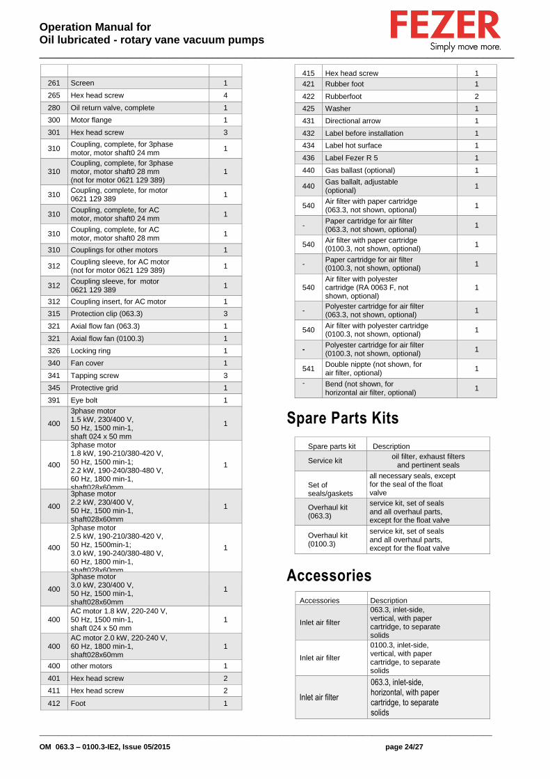
Spare Parts
Note: When ordering spare parts or accessories acc. to the table below please always quote the type ("Type") and the serial no. ("No") of the vacuum pump. This will allow Fezer service to check if the vacuum pump is compatible with a modified or improved part.
The exclusive use of genuine spare parts and consumables is a prerequisite for the proper function of the vacuum pump and for the granting of warranty, guarantee or goodwill.
This parts list applies to a typical configuration of the vacuum pump 063.3 – 0100.3. Depending on the specific order deviating parts data may apply.
Your point of contact for service and spare parts in Germany:
ALBERT FEZER MASCHINENFABRIK GMBH HAUPTSTR. 37-39 D-73730 ESSLINGEN GERMANY TEL.: +49 (0) 711/36 009-0 FAX: +49 (0) 711/36 009-40 MAIL: [email protected]
Find the up-to-date list of Fezer companies and agencies all over the world on the internet at www.fezer.com.
Pos. Part Qty
1 Cylinder (063.3) 1
1 Cylinder (0100.3) 1
14 Rotor with shaft sleeves (063.3)
1
14 Rotor with shaft sleeves (0100.3)
1
Pos. Part Qty
18 Shaft sleeve 2
22 Vane (063.3) 3
22 Vane (0100.3) 3
24 Cylinder cover A-side, complete 1
27 Cylinder cover B-side, complete 1
30 Needle bearing 2
35 Shaft seal ring 2
42 Supporting washer 2
43 Tapping screw 4
46 Seal ring 1
47 Plug 1
50 0-ring 2
53 Hex head screw 5
57 Fit screw 1
60 Taper pin 3
65 Parallel key 1
66 Parallel key 1
75 Oil separator (version with float valve and oil return line)
1
75 Oil separator (version with oil return valve) 1
83 Sight glass 1
84 Gasket 1
88 Plug 1
89 0-ring 1
95 Plug 1
96 0-ring 1
99 Nipple 1
100 Oil filter 1
105 Drum plug 2
106 O-ring 2
120 Exhaust filter with o-ring 2
125 Filter spring 2
136 Round gasket-service cover 1
138 Hex head screw 4
139 Service cover 1
141 Gasket 2
146 Hex head screw 8
155 Exhaust cover plate, complete 2
159 Exhaust valve, complete 2
185 Gasket 1
186 Stud bolt 4
191 Hex nut 4
195 Oil return line, complete 1
200 Float valve, complete 1
210 Oil supply (063.3, w/o cooling coil), complete
1
210 Oil supply (0100.3, with cooling coil), complete
1
250 Inlet flange, lower part 1
255 O-ring 2
257 Valve insert, complete 1
260 Inlet flange 1
Operation Manual for Oil lubricated - rotary vane vacuum pumps _____________________________________________________________________________
__________________________________________________________________________________________________
OM 063.3 – 0100.3-IE2, Issue 05/2015 page 24/27
261 Screen 1
265 Hex head screw 4
280 Oil return valve, complete 1
300 Motor flange 1
301 Hex head screw 3
310 Coupling, complete, for 3phase motor, motor shaft0 24 mm
1
310 Coupling, complete, for 3phase motor, motor shaft0 28 mm (not for motor 0621 129 389)
1
310 Coupling, complete, for motor 0621 129 389
1
310 Coupling, complete, for AC motor, motor shaft0 24 mm
1
310 Coupling, complete, for AC motor, motor shaft0 28 mm
1
310 Couplings for other motors 1
312 Coupling sleeve, for AC motor (not for motor 0621 129 389)
1
312 Coupling sleeve, for motor 0621 129 389
1
312 Coupling insert, for AC motor 1
315 Protection clip (063.3) 3
321 Axial flow fan (063.3) 1
321 Axial flow fan (0100.3) 1
326 Locking ring 1
340 Fan cover 1
341 Tapping screw 3
345 Protective grid 1
391 Eye bolt 1
400
3phase motor 1.5 kW, 230/400 V, 50 Hz, 1500 min-1, shaft 024 x 50 mm
1
400
3phase motor 1.8 kW, 190-210/380-420 V, 50 Hz, 1500 min-1; 2.2 kW, 190-240/380-480 V, 60 Hz, 1800 min-1, shaft028x60mm
1
400
3phase motor 2.2 kW, 230/400 V, 50 Hz, 1500 min-1, shaft028x60mm
1
400
3phase motor 2.5 kW, 190-210/380-420 V, 50 Hz, 1500min-1; 3.0 kW, 190-240/380-480 V, 60 Hz, 1800 min-1, shaft028x60mm
1
400
3phase motor 3.0 kW, 230/400 V, 50 Hz, 1500 min-1, shaft028x60mm
1
400 AC motor 1.8 kW, 220-240 V, 50 Hz, 1500 min-1, shaft 024 x 50 mm
1
400 AC motor 2.0 kW, 220-240 V, 60 Hz, 1800 min-1, shaft028x60mm
1
400 other motors 1
401 Hex head screw 2
411 Hex head screw 2
412 Foot 1
415 Hex head screw 1
421 Rubber foot 1
422 Rubberfoot 2
425 Washer 1
431 Directional arrow 1
432 Label before installation 1
434 Label hot surface 1
436 Label Fezer R 5 1
440 Gas ballast (optional) 1
440 Gas ballalt, adjustable (optional)
1
540 Air filter with paper cartridge (063.3, not shown, optional)
1
- Paper cartridge for air filter (063.3, not shown, optional)
1
540 Air filter with paper cartridge (0100.3, not shown, optional)
1
- Paper cartridge for air filter (0100.3, not shown, optional)
1
540 Air filter with polyester cartridge (RA 0063 F, not shown, optional)
1
- Polyester cartridge for air filter (063.3, not shown, optional)
1
540 Air filter with polyester cartridge (0100.3, not shown, optional)
1
- Polyester cartridge for air filter (0100.3, not shown, optional)
1
541 Double nippte (not shown, for air filter, optional)
1
- Bend (not shown, for horizontal air filter, optional)
1
Spare Parts Kits
Spare parts kit Description
Service kit oil filter, exhaust filters
and pertinent seals
Set of seals/gaskets
all necessary seals, except for the seal of the float valve
Overhaul kit (063.3)
service kit, set of seals and all overhaul parts, except for the float valve
Overhaul kit (0100.3)
service kit, set of seals and all overhaul parts, except for the float valve
Accessories
Accessories Description
Inlet air filter
063.3, inlet-side, vertical, with paper cartridge, to separate solids
Inlet air filter
0100.3, inlet-side, vertical, with paper cartridge, to separate solids
Inlet air filter
063.3, inlet-side, horizontal, with paper cartridge, to separate solids

Operation Manual for Oil lubricated - rotary vane vacuum pumps _____________________________________________________________________________
__________________________________________________________________________________________________
OM 063.3 – 0100.3-IE2, Issue 05/2015 page 25/27
Accessories Description
Inlet air filter
0100.3, inlet-side, horizontal, with paper cartridge, to separate solids
Inlet air filter
063.3, inlet-side, vertical, with polyester cartridge, food proof, to separate solids
Inlet air filter
0100.3, inlet-side, vertical, with polyester cartridge, food proof, to separate solids
InIet air filter
063.3, inlet-side, horizontal, with polyester cartridge, food proof, to separate solids
Inlet air filter
0100.3, inlet-side, horizontal, with polyester cartridge, food proof, to separate solids
Filter pressure gauge
for easy checking of the degree of clogging of the exhaust filter
Vacuum regulating unit
to adjust the required working pressure; connection R11/4"
Gas Ballast, complete
for the conveying of condensable vapours, with sinter metal filter
Gas Ballast, adjustable, complete
for the conveying of condensable vapours, with sinter metal filter and ball valve valve
Motor safety switch
adjustment range: 1.6 - 2.4 A, 3 Ph.
Motor safety switch
adjustment range: 2.4 - 4.0 A, 3 Ph.
Motor safety switch
adjustment range: 4.0 - 6.0 A, 3 Ph.
Motor safety switch
adjustment range: 6.0 -10 .0 A, 3 Ph.
Motor safety switch
adjustment range: 10.0 - 16.0 A, 3 Ph.
Motor safety switch
adjustment range: 10.0 - 16.0 A, 1 Ph.
Liquid and dust separator STF 0100
to protect against solids and liquids on the suction side
Liquid separator LSS 0100
to protect against condensate and liquids on the suction side
Liquid separator LSA 0100
to protect against condensate and liquids on the suction side, with automatic draining
Accessories Description
Cyclone separator CYC 0100
for extracting liquids from gases and mixtures of gases

Operation Manual for Oil lubricated - rotary vane vacuum pumps _____________________________________________________________________________
__________________________________________________________________________________________________
OM 063.3 – 0100.3-IE2, Issue 05/2015 page 26/27
Oil
Denomination VM 032 VM 068 VM 100 VE 101 VMH 100 VSL 032 VSL 068 VSL 100
ISO-VG 32 68 100 100 100 32 68 100
Base Mineral oil Mineral oil Mineral oil Diester Mineral oil PAO PAO PAO
Density [g/cm3] 0.872 0.884 0.888 0.96 0.87 0.83 0.83 0.84
Ambient temperature range [ ° C ]
0 ... 10 5 ... 20 12 ... 30 12 ... 40 12 ... 30 -5 ... 10 5 ... 20 10 ... 40
Kinematic viscosity at 40 °C [mm
2/s]
30 68 110 95 94 32 68 96
Kinematic viscosity at 100 °C [mm
2/s]
5 8.5 11.5 9.5 - 6 10 13
Flashpoint [ ° C ] 225 235 260 255 264 240 240 240
Pourpoint [ ° C ] -15 -15 -15 -30 -15 -60 -55 -50
Remark
Standard oil
for non-de- manding appli-
cation
Standard oil
for non-de- manding appli-
cation
Standard oil
for non-de- manding appli-
cation
For thermally
and chemically demanding
applications
For ultimate
Pressure criti-
applications
Food applica-
tions (NSF HI)
Food applica-
tions (NSF HI)
Food applica-
tions (NSF HI)
Filling quantity, approx. [I] 2.0
Operation Manual for Oil lubricated - rotary vane vacuum pumps _____________________________________________________________________________
__________________________________________________________________________________________________
OM 063.3 – 0100.3-IE2, Issue 05/2015 page 27/27
EC Declaration of Conformity as per enclosure II A
In accordance with the Machines 2006/42 EC CE-Regulations for: Low voltage 2006/95/EC Electromagnetic compatibility 2004/108/EC
Construction of Machine: Vacuum pump VP-063.3-Europe-IE2
VP-063.3-Multi-IE2 VP-063.3-Brazil-IE2 VP-0100.3-Europe-IE2 VP-0100.3-Multi-IE2 VP-0100.3-Brazil-IE2
Is developed, constructed and manufactured in accordance with the above-mentioned CE-Regulations, in exlusive responsibility of: Albert Fezer Maschinenfabrik GmbH Hauptstrasse 37 – 39 D-73730 Esslingen
The following harmonized standards are applied: Document-No. Description Issue
DIN EN ISO 12100 Safety of machinery 2011 - 03 DIN EN ISO 13857 Safety of machinery, safety distances 2008 - 06 DIN EN 1012 -1 Compressors and vacuum pumps, safety requirements, part 1 2011 - 02 DIN EN 1012 -2 Compressors and vacuum pumps, safety requirements, part 2 2011 - 12 DIN EN 60204-1 Electrical equipment of machines, part 1 2011 - 01 DIN EN 61000-6-1 Electromagnetic compatibility, Generic immunity standards, part 6-1 2007 –10 DIN EN 61000-6-2 Electromagnetic compatibility, Generic immunity standards, part 6-2 2011– 06 DIN EN 61000-6-3 Electromagnetic compatibility, Generic emission standards, part 6-3 2011 - 09 DIN EN 61000-6-4 Electromagnetic compatibility, Generic emission standards, part 6-4 2011 - 09 DIN EN ISO 2151 Acoustic-compressors and vacuum-pumps 2009 - 01 The technical documentation and original manuals are available through Albert Fezer Maschinenfabrik GmbH. Name of the undersigned: Georg Komposch Berthold Eger Address: Alber Fezer Maschinenfabrik GmbH Albert Fezer Maschinenfabrik GmbH Place of issue: Esslingen Esslingen Date of issue: 06.05.2015 06.05.2015
_____________________________________________________________________________________________ Task of the undersigned: general manager person in charge for documentation
When integrating the vacuum pump into a higher-ranking machine or equipment the manufacturer (who can also be the operator) of the higher-ranking machine or equipment has to carry out the conformity test process for the higher-ranking machine or equipment as per the regulations “machines” 2006/42/EC, fill in the declaration of conformity and attach the CE label.


![U 5[inch] 2.6 10. 9 1 G2 6 5.3 5.1 0. 6 9. 7 4. 6 6 6 7.1 12.2 17.6 0.8 15 │ rotary vane vacuum pumps, oil-lubricated :: U 4.165 U 5.200 Rotary vane vacuum pumps oil-lubricated and](https://img.dokumen.tips/doc/110x75/5e4a5e78c665b375a83e103d/u-5-inch-26-10-9-1-g2-6-53-51-0-6-9-7-4-6-6-6-71-122-176-08-15-a.jpg)