Embed Size (px)
Citation preview

200 NEWSOME DRIVEYORKTOWN, VA 23692
Telephone: 757.988.3930Toll Free: 800.535.4243
Web Site: www.travaini.com Fax: 757.988.3975
Continuing research of TRAVAINI PUMPS USA results in product improvements; therefore any specifications may be subject to change without notice.
PRINTED IN USAF:/MVUOTGB4
DATE 4/02
Operating &MaintenanceManualforLiquid Ring
Vacuum Pumps,Compressors& Systems
TRH-TRS-TRM-TRV-SAWater Sealed & Oil Sealed (DynaSealTM)
Systems
Liquid Ring & Rotary Vane Vacuum Pumps and Systems
Liquid Ring & Rotary Vane Vacuum Pumps and Systems

OUR PRODUCTS
LIQUID RINGVACUUM PUMPS
LIQUID RING COMPRESSORS
ROTARY VANE VACUUM PUMPS
ROTARY VANE VACUUM SYSTEMS
MEDICAL SYSTEMS (NFPA99)
PACKAGE VACUUM SYSTEMS WITH PARTIAL OR TOTAL SERVICE RECIRCULATION
CUSTOM ENGINEEREDVACUUM SOLUTIONS
This manual applies to TRAVAINI PUMPS USAliquid ring pumps single stage series TRM, TRS,TRV, double stage series TRH, compressorsseries SA and systems series water sealed andoil sealed (DynaSealTM) Systems, which utilizeabove pump series. (Please see section 18 or 19for details pertaining to systems).
NOTE: Unless otherwise specified, the termpump used throughout this manual means alsopump/motor assembly or system type watersealed or oil sealed (DynaSealTM).
MANUFACTURER:
TRAVAINI PUMPS USA200 Newsome DriveYorktown, VA 23692Telephone: (757) 988-3930Fax: (757) 988-3975Website: www.travaini.com
WARRANTY:All products manufactured by TRAVAINI PUMPSUSA are guaranteed to meet the conditionslisted on the general terms & conditions of salesand/or conditions listed on the order confirma-tions. Failure to strictly adhere to the instructionsand recommendations listed in this manual, willvoid the manufacturer’s warranty. Detailedwarranty policy can be found in Section 21.
PROPRIETY DOCUMENT:This document and the information enclosedherein are proprietary to Travaini Pumps USA andmust, along with any copies, be returned upondemand. Reproduction or use of any informationdisclosed herein, or the manufacture of anyassembly or part depicted herein is permissibleonly to the extent expressly authorized in writingby Travaini Pumps USA on and for which thisdocument is provided.
In preparing this manual, every possible effort has been madeto help the customer and operator with the proper installationand operation of the pump and/or system. Should you finderrors, misunderstandings or discrepancies please do nothesitate to bring them to our attention.
OPERATINGMANUAL FORINSTALLATION,START-UP ANDMAINTENANCEFOR LIQUIDRING VACUUMPUMPS,COMPRESSORSAND SYSTEMS
“Proven Designs”Liquid Ring & Rotary Vane Vacuum Pumps and Systems

SECTION PAGE
9.9 Typical installation schematics for vacuum pumps ............... 18
9.10 Typical installation schematics for compressors .................. 19
9.11 Connections location.......................................................... 20
9.12 Pump engineering data....................................................... 23
10 Check list prior to start-up............................................................. 25
11 Starting, operating and stopping procedures .................................. 25
11.1 Start-up of “WATER SEALED” system .................................. 26
11.2 Operation of “WATER SEALED” system................................ 26
11.3 Shut down of “WATER SEALED” system............................... 27
11.4 Start-up of “OIL SEALED (DynaSeal™)” systems .................. 27
11.5 Operation of “OIL SEALED (DynaSeal™)” systems................ 27
11.6 Shut down of “OILSEALED (DynaSeal™)” systems................ 28
12 Operating maintenance ................................................................. 28
12.1 “OIL SEALED (DynaSeal™)” systems ................................... 29
13 Bearings and mechanical seals maintenance ................................. 30
13.1 Bearings............................................................................ 31
13.2 Mechanical seals............................................................... 31
14 Trouble shooting: problems, causes and solutions.......................... 33
15 Repairing and removing pump from the installation......................... 34
16 Spare parts.................................................................................. 35
17 Engineering data........................................................................... 36
17.1 Influence of service liquid temperature, specific gravity ........ 36and viscosity on pump performance
17.2 Service liquid temperature change across the pump ............ 37
17.3 Operation with partial recovery of service liquid................... 38
17.4 Units conversion table........................................................ 39
18 Engineering data for “WATER SEALED” systems.............................. 40
19 Engineering data for “OIL SEALED (DynaSeal™)” systems ............... 42
20 Product Data Information Form ...................................................... 44
21 Warranty Policies - Vacuum Pumps, Compressors and Systems ....... 45
TABLE OF CONTENTS
SECTION PAGE
1 General instructions...................................................................... 1
2 Safety instructions........................................................................ 1
3 In case of emergency.................................................................... 2
3.1 Basic first aid .................................................................... 2
4 Pump outlines .............................................................................. 3
4.1 Principle of operation ......................................................... 3
4.2 Service liquid properties .................................................... 3
4.3 Pump models and tables for material of construction........... 3
5 Uncrating, lifting and moving instructions ....................................... 4
6 Storage instructions...................................................................... 7
7 Mounting and alignment instructions.............................................. 7
7.1 Assembly of base mounted pump unit................................. 7
7.2 Alignment procedures for monoblock and for ....................... 8pump/motor assembly on baseplate
7.3 Alignment instructions........................................................ 8
8 Electrical connections ................................................................... 11
9 Installation instructions................................................................. 12
9.1 Piping connections............................................................. 13
9.2 Accessories....................................................................... 13
9.3 Installation schematics for vacuum pumps .......................... 14
9.3.1 Service liquid: Once-through system (no recovery) ............... 14
9.3.2 Service liquid: Partial recovery system................................ 14
9.3.3 Service liquid: Total recovery system .................................. 14
9.4 Installation schematics for compressors ............................. 15
9.5 Installation of “WATER SEALED” systems ............................ 15
9.6 Installation of “OIL SEALED (DynaSeal™)” systems.............. 15
9.7 Service liquid (H2O at 60° F) flow (in ACFM) for .................... 16vacuum pumps
9.8 Service liquid flow (H2O at 60° F) and pressure for .............. 17compressors series “SA”

When approaching the pump ALWAYS be properly dressed (avoid use ofclothing with wide sleeves, neckties, necklaces, etc.) and/or wear safety equipment (hard hat, safety glasses, safety shoes, etc.) adequate for the work to be done.
• ALWAYS stop the pump prior to touching it, regardless of the reason.• ALWAYS disconnect the power to the motor prior to working or removing the
pump from the installation.• NEVER work on the pump when it is hot.• After completion of the work ALWAYS re-install the safety guards previously
removed.• ALWAYS be careful when handling pumps that convey acids or hazardous
fluids.• ALWAYS has a fire extinguisher in the vicinity of the pump installation.• DO NOT operate the pump in the wrong direction of rotation.• NEVER put hands or fingers in the pump or system openings or cavities.• NEVER step on pump and/or piping connected to the pump.• Pump or piping (connected to the pump) must NEVER be under pressure or
vacuum when maintenance or repair is carried out.NOTE: There are materials in the pump that may be hazardous to people sufferingfrom allergies. Maintenance and operating personnel should consult Table 1 forsuch materials.
TABLE 1MATERIAL USE POSSIBLE DANGEROil and Grease General lubrication, ball Skin and eye irritation
or roller bearingsPlastic and elastomer O-Ring, V-Ring, Splash ring, Release of fumes andcomponents Oil seals vapours when overheatedTeflon & Kevlar fibers Packing rings Release of dangerous
powders, release of fumes when overheated
Varnishes Exterior pump surface Release of powder and fumes in case of rework, flammable
Protective liquid Pump inside surface Skin and eye rashLiquid compound Gasket between flat surfaces Skin, eye and breathing
organs irritation
3 - IN CASE OF EMERGENCY Should the pump break down leak gas and/or service liquid, immediately discon-nect the electrical power following the instructions given in section 11. Alert themaintenance personnel, at least two people should intervene using precautions,as it is required for the specific installation: pump may be handling dangerousand/or hazardous fluids.
After correction of all the problems that created the emergency situation, it isnecessary to carry out all the recommended starting procedures (see section 10).
3.1 - BASIC FIRST AIDIn the event dangerous substances have been inhaled and/or have come incontact with the human body, immediately contact the medical staff and follow theinstructions given by the company’s internal medical safety procedures.
– 2 –– 1 –
1 – GENERAL INSTRUCTIONS
This manual is intended to provide reference to:- application and operating safety - installation and maintenance for pump or system- starting, operating and stopping procedures for pump or system
NOTE: All references made to pumps are also applicable to systems that employthese pumps, unless otherwise specified.
Upon receipt of this manual, the operator should complete the Product Data sheetwith the requested data. The manual should then be read CAREFULLY and kept ina safe file for future reference. It should always be available to the qualified oper-ating and maintenance personnel responsible for the safe operation of the pumpor system. (Qualified personnel should be experienced and knowledgeable ofSafety Standards, should be recognized by the safety department manager asbeing capable to effectively act on safety issues, should the need arise and knowl-edge of first aid should also be required).
The pump is to be used only for the applications specified on the confirming order for which TRAVAINI PUMPS USA has selected the design, materials of construction and tested the pump to meet the order specifications. Therefore, the pump or system CANNOT be used for applications other than those specified on the orderconfirmation.
In the event the pump is to be used for different applications, please consultTRAVAINI PUMPS USA or a representative of the manufacturer. TRAVAINI PUMPSUSA declines to assume any responsibility if the pump is used for differentapplications without prior written consent. The user is responsible for the verifi-cation of the ambient conditions where the pump will be stored or installed.Extreme low or high temperatures may severely damage the pump or systemunless proper precautions are taken. TRAVAINI PUMPS USA does not guaranteerepairs or alterations done by user or other unauthorized personnel. Specialdesigns and constructions may vary from the information given in this manual.Please contact TRAVAINI PUMPS USA should you have any difficulty or doubt.
NOTE: Drawings appearing in this manual are only schematics. These drawings arenot for construction.
2 - SAFETY INSTRUCTIONSCAUTION: CAREFULLY READ FOLLOWING INSTRUCTIONS.
STRICTLY ADHERE TO THE INSTRUCTIONS LISTED BELOW TO PREVENT PERSONAL INJURIES AND/OR EQUIPMENT DAMAGE.
• ALWAYS apply the pump for the conditions outlined on the confirming order.• Electrical connections on the motor or accessories must ALWAYS be carried
out by authorized personnel and in accordance to the local codes.• Any work on the pump should be carried out by at least 2 people.

4.3 - PUMP MODELS AND TABLES FOR MATERIAL OF CONSTRUCTIONOn the pump nameplate are printed the pump serial number, the year of manu-facture and the pump model. Refer to the following example for understanding thecoding of the pump model. Every letter or number in the pump model designationhas a specific meaning relating to the pump design.
Example of pump model number:
T R H C 80 - 750 / C - M / GH
STANDARD materials of constructionVDMA Description GH F RZ RA A3106 Suction casing107 Discharge casing Cast iron 1561137 Intermediate plate110 Center body Carbon Steel210 Shaft Stainless steel AISI 420 Stainless steel
AISI 316147 Manifold Carbon steel357 Bearings & M.S. Hous. Cast iron 1561230 Impeller DuctileBronze iron Stainless steel AISI 316
For additional details regarding standard or special materials contact TRAVAINIPUMPS USA.
5 - UNCRATING, LIFTING ANDMOVING INSTRUCTIONS
Upon receipt, verify that the material received is in exact compliance with thatlisted on the packing slip.
When uncrating, follow the instructions listed below:• check for visible damages on the crate that could have occurred during
transport• carefully remove the packaging material• check the pump/or accessories such as tanks, piping, valves, etc. to
ensure that it is free of visible markings such as dents and damage which may have occurred during transportation
• in the event of damage, report this immediately to the transport company and to TRAVAINI PUMPS USA Customer Service department.
Discard through controlled disposals all packaging materials that may constitutepersonal injury (sharp objects, nails, etc.).
– 4 –
4 - PUMP OUTLINESThe instructions given in this manual are for liquid ring vacuum pumps and com-pressors and for systems type WATER SEALED or OIL SEALED (DynaSealTM) whichutilize said pumps.
NOTE: Capacities, vacuum and pressures are nominal and are the maximumattainable values under standard operating conditions. Please contact TRAVAINIPUMPS USA for data on liquid ring compressors series TR…
TRM Single stage liquid ring vacuum pumps Capacity to 210 ACFM, max vacuum 33 mbar (25 Torr)
TRS Single stage liquid ring vacuum pumpsCapacity to 2100 ACFM, max vacuum 150 mbar (100 Torr)
TRV Single stage vacuum pumpsCapacity to 300 ACFM, max vacuum 33 mbar (25 Torr)
TRH Two stage liquid ring vacuum pumpsCapacity to 2100 ACFM, max vacuum 33 mbar (25 Torr)
SA Double acting liquid ring compressorsCapacity to 110 ACFM, pressures to 10 bar–(145 psig)
4.1 - PRINCIPLE OF OPERATION(See figure at side)The aspirated gas enters the pump chamber A-Bvia the pump suction flange. The gas is trappedbetween two (2) impeller vanes. The impellerrotates eccentrically in relation to the centerline ofthe liquid ring that, by centrifugal force, assumesthe shape of the impeller casing. The progressivechange of volume between the two (2) vanes, theimpeller hub and the liquid ring first creates avacuum and then a compression of the gas in theB-C area till the gas is discharged, together with aportion of the liquid, through the discharge portC-D. The lost liquid must then be replenished.
4.2 - SERVICE LIQUID PROPERTIESFor good operation, the liquid ring pumps must be supplied with a service liquid,which is clean, non-abrasive and free of any solids. The service liquid tempera-ture should not exceed 80 °C and the gas handled should be maximum 100 °C;the liquid density should be between 0.8 and 1.2 g/cm3 and the viscosity shouldbe less than 40 °C (the pump performance will change if the service liquid hasproperties different than those of water at 15°C (60°F). All engineering data isbased on the use of 15°C (60°F) as service liquid, see section 17 for additionalinformation. Contact TRAVAINI PUMPS USA before using liquids with propertiesoutside the ranges listed above.
– 3 –
T – Manufacturer POMPETRAVAINIR – Liquid ring pumpH – M and V = Single stage pump
with high vacuumS = Single stage pump with
medium vacuumH = Two stage pump with high
vacuumC – Revision of hydraulic design80 – Ø Flange size (mm)
750 – Nominal capacity in m3/hC – C = Shaft sealing by mechanical
sealB = Shaft sealing by stuffing box
M – Monoblock design with motor flange (upon request)
GH – Material of constructionGH - F - RZ - RA - A3(see following table)

– 6 –
The pump or assembly must ALWAYS be moved and transported in the horizontalposition. Prior to moving the unit find the following:
• total weight• center of gravity• maximum outside dimensions• lifting points location.
For safe lifting to prevent material damages and/or personal injuries is recommended to use ropes, or belts properly positioned on the pump and/or lifting eyebolts and make correct movements.NOTE: Lifting eyebolts fitted on single components of the assembly (pump or motor) should not be used to lift the total assembly.
Avoid lifts whereby the ropes or straps, form a triangle with the top angle over 90°(see fig. 3). The fig. 4 shows several additional examples of lifting to be avoided.Prior to moving the unit from an installation, always drain any pumped fluid fromthe pump, piping and accessories, rinse and plug all openings to prevent spillage.For instructions to remove the unit from installation see section 15.
– 5 –
OK
NO
Flexible couplings must be properly aligned. Bad alignments will result in couplingfailures and damage to pump and motor bearings.
Assembly instructions for MONOBLOCK design are listed on paragraph 7.3 steps 1, 2, 4, 5, 6.
Assembly instructions for PUMP-MOTOR ON BASEPLATE are listed on paragraph 7.3 steps 7, 1, 8, 5, 9, 10, 11.
For pump driven with V-Belt, please consult TRAVAINI PUMPS USA for furtherinformation.
7.2 - ALIGNMENT PROCEDURES FOR MONOBLOCK AND FOR PUMP/MOTORASSEMBLY ON BASEPLATE.TRAVAINI PUMPS USA prior to shipment properly aligns the pump/motor assembly.It is however required to verify the alignment prior to the start-up. Misalignmentcan occur during handling, transportation, grouting of assembly, etc.
For alignment procedures of MONOBLOCK design see paragraph 7.3 steps 3, 4, 5, 6.
For alignment procedure of BASEPLATE design see paragraph 7.3 steps 7, 5, 9, 10, 11.
NOTE: Coupling sizes and permissible coupling tolerances listed in this manual are applicable to the particular coupling brand installed by TRAVAINI PUMPS USAas a standard. For sizes and tolerances of other type of couplings, follow theinstructions given by their respective manufacturer.
7.3 - ALIGNMENT INSTRUCTIONSNOTE: Alignment should be done at ambient temperature, with power to the motor disconnected and following the safety procedures to avoid accidental start-ing (see section 2).
Should the pump operate at high temperatures that could upset the coupling align-ment, it is necessary to check the alignment to secure proper working operationat such operating temperatures. It is recommended the use of proper hand pro-tections such as gloves, when carrying out the operations listed below (schemat-ics for various assemblies are shown).
NOTE: The following points must be followed with the sequence stated above anddepending upon the type of operation: alignment assembly or alignment verifica-tion.
1 - Thoroughly clean motor/pump shaft ends and shaft keys, place the shaft keysin the proper key way slots and fit the coupling halves in line with the shaft ends.The use of rubber hammers and even pre-heating of the metal half couplings maybe required (see fig. 5). Lightly tighten the set screws. Verify that both pump andmotor shafts rotate freely.
– 8 –
6 - STORAGE INSTRUCTIONSAfter receipt and inspection, if not immediately installed, the unit must be repack-aged and stored. For a proper storage proceed as follows:• store the pump in a location that is closed, clean, dry and free of vibrations• do not store in areas with less than 5 °C (41 °F) temperature (for lower
temperature it is necessary to completely drain the pump of any liquids that are subject to freezing)
FREEZING DANGER!Where the ambient temperature is less than 5 °C (41°F) it isrecommended to drain the pump, piping, separator, heat exchanger,etc. or add an anti-freeze solution to prevent damage to theequipment.
• fill the pump halfway with an anti-rust liquid but compatible with gaskets andelastomers materials, rotate the pump shaft by hand so that all internal partsget wet and then drain the pump of the excessive anti-rust liquid
• plug all openings that connect the pump internals to the atmosphere• protect all machined surfaces with an anti-rust material (grease, oils, etc.)• cover the unit with plastic sheet or similar protective material• rotate pump shaft at least every three months to avoid possible rust build-up
which may result in seizing of the pump.• pump accessories should be subjected to similar procedure.
7 - MOUNTING AND ALIGNMENT INSTRUCTIONS7.1 - ASSEMBLY OF BASE MOUNTED PUMP UNIT
In some cases such as bare pump orders, pumps are shipped with anti-rust and anti-freeze agents. Ensure pump is thoroughly flushed and these agents are removed prior to installation.
If the pump has been purchased with a free shaft end, a proper baseplate isrequired to mount the pump/motor assembly. The baseplate must be properlydesigned for maximum rigidity to prevent vibrations and distortions. It is recom-mended the use of a fabricated baseplate manufactured with rigid “U” shapedchannel (fig. 16 illustrates an example).
When the pump has been purchased without the electric motor, it is then requiredto select the proper motor before proceeding to the installation of the unit. Whenselecting a motor the following must be considered:• maximum power absorbed by the pump over the total operating range• pump operating speed (RPM)• available power (Hertz, voltage, etc.)• motor enclosure type (ODP, TEFC, EX.PR., etc.)• motor mount (B3, B5, horizontal, vertical, C-flange, D-flange, etc.).
When selecting Flexible couplings the following must be considered:• nominal motor horsepower• motor operating speed• coupling guard must meet safety standards as dictated by OSHA, etc.
– 7 –

8 - Place the electric motor on the baseplate and bring the two coupling halvestogether with approx. 2mm gap between them keeping the motor axially alignedwith the pump shaft. In the event the two shaft heights do not align, proper shim-ming under the pump or motor feet will be required. Mark the motor and/or pumpanchoring bolt holes. Remove motor and/or pump, drill and tap the holes, cleanand mount pump and/or motor in place and lightly tighten the bolts (see fig. 11).
9 - With a straight edge ruler check the parallelism of the two coupling halves atseveral points, 90° from each other (see fig. 13).NOTE: Easier and more accurate readings can be attained with instruments suchas Dial Indicators (if readily available).
If the maximumvalue of “X” ishigher than thatlisted in the table2 (for the given coupling size) itwill be required tocorrect the align-ment by using shims under the pump or motor feet. When the measured valuesfall within the tolerances (tolerances only given for “S”), the pump and motormounting bolts can be tightened.
– 10 –
2 - Insert the perforated metal sheet couplingguard inside the lantern so that the couplingis accessible from one of the lateral open-ings. Couple the electric motor to the pumplantern engaging the two coupling halves,hands may reach the coupling halves throughthe lateral opening (see fig. 7) tighten theassembly with bolts supplied with the unitand install the supporting foot, when applica-ble (see fig. 6).3 - Applying slight hand pressure to the cou-pling guard, rotate it so that one opening of the lantern is accessible (see fig. 8).
4 - Rotate by hand the coupling through the lateral opening of the lantern to makesure the pump is free.5 - With a feeler gauge, check the distance between the two coupling halves. Thegap value “S” should be as listed on table 2 or as given by the coupling manu-facturer. In the event, an adjustment is necessary, loosen the set screws on thecoupling half and with a screw driver move the coupling half to attain the gap “S”(see fig. 12). Then tighten the set screw and rotate the rotor by hand to makesure, once more, that there is no obstruction.6 - Rotate back the coupling guard by hand through the two openings of the lanternso that both openings are completely covered. This will complete the alignmentverification of the MONOBLOCK design.7 - Remove the coupling guard and its extension (if there is one) attached to thepump, by removing the two locking screws (see fig. 9 and 10).
– 9 –

start, to avoid electrical overloads to the motor and mechanical overloads to thepump. Be sure to replace all safety guards before switching on the electricalpower. If possible check the direction of rotation before the motor is coupled tothe pump but protect the motor shaft to prevent any accidents. When this is notpossible briefly jog the pump to check its direction of rotation (see arrow on pumpfor correct rotation). If the direction must be changed two of the three electricalwire leads must be alternated with each other (at the terminal box or at the motorstarter). Be aware that rotation in the wrong direction and/or pump running drymay cause severe pump damage. Electrical instrumentation such as solenoidvalves, level switches, temperature switches, etc. which are supplied with thepump or systems must be connected and handled in accordance with the instruc-tions supplied by their respective manufacturers. Contact TRAVAINI PUMPS USAfor specific details.
9 - INSTALLATION INSTRUCTIONSInformation to determine the piping sizes and floor space requirements can beobtained from dimensional drawings and other engineering data. The informationrequired is:• size and location of suction and discharge flanges• size and location of service liquid connection and connections for cooling,
heating, flushing, draining, etc.• location and size for mounting bolts for monoblock pump and/or baseplate
and/or frame.
In the event additional accessories are required to complete the installation suchas separators, piping, valves, etc. refer to sections 9.2 to 9.8. Proper liftingdevices should be available for installation and repair operations. Pump assem-bly should be installed in an accessible location with adequate clear and cleanspace all around for maintenance, so that an efficient and proper installation canbe made. It is important to have proper room around the unit for ventilation ofmotor and air-cooled radiator, if applicable. Avoid installing the unit in hidden loca-tions, dusty and lacking of ventilation. Select a mounting pad that will minimizevibrations or torsion of the pump baseplate or frame. It is generally preferred tohave a concrete base or sturdy steel beams. It is important to provide adequateanchor bolting for the pump frame or baseplate to be firmly attached to the foun-dations (see fig. 16).
Concrete pads and other concrete works must be aged, dry and clean before thepump assembly can be positioned in place. Complete all the work relating to thefoundations and grouting of the pump assembly, before proceeding with themechanical and electrical portion of the installation.
– 12 –
10 - Angular misalignment can be measured with aCaliper. Measure the outside coupling dimension at sev-eral points (see fig. 14). Find the minimum and maxi-mum width of the coupling, the difference betweenthese two readings “Y” (Y1-Y2) should not exceed thevalue listed in table 2 for the given coupling size.Should this value be greater it will be necessary to cor-rect the alignment by shimming the pump and/or motor.Following this operation it is recommended to checkonce more the value “X” to make sure that both valuesare within the allowed tolerance (see point 9). Make
sure that both set screws on the coupling halves are properly secured.
Table 2COUPLING GAP PARALLEL ANGULAR“Ø A” mm “S” mm “X” mm “Y” mm
60 2 to 2.50 0.10 0.2080 2 to 2.50 0.10 0.20100 2 to 2.50 0.15 0.25130 2 to 2.50 0.15 0.25150 3 to 3.75 0.15 0.30180 3 to 3.75 0.15 0.30200 3 to 3.75 0.15 0.30
11 - Install the couplingguard and its extension (ifapplicable) on the pump,secure the two lockingbolts. The gap betweenmotor frame and the guardshould not be greater than 2to 3mm (see fig. 15).
8 - ELECTRICAL CONNECTIONSElectrical connections must be made exclusively by qualified personnel in accordance with the instructions from the manufacturerof the motor or other electrical components and must adhere to the local National Electrical Code.
FOLLOW ALL SAFETY PRECAUTIONS AS LISTED IN SECTION 2. BEFORE DOING ANY WORK TO THE INSTALLATION, DISCONNECT ALL POWER SUPPLIES.
It is recommended that electric motors be protected against overloading by meansof circuit breakers and/or fuses. Circuit breakers and fuses must be sized inaccordance with the full load amperage appearing on the motor nameplate. It isadvisable to have an electrical switch near the pump for emergency situations.Prior to connecting the electrical wiring, turn the pump shaft by hand to make surethat it rotates freely. Connect the electrical wiring in accordance with local electri-cal codes and be sure to ground the motor. Motor connection should be as indi-cated on the motor tag (frequency and voltage) and as discussed in the motorinstruction manual. It is recommended that motors over 75Hp be wired for soft
– 11 –

Heat exchangerIt cools the service liquid for those systems with total liquid recovery: it can beplate and frame, shell and tube or radiator type, depending upon the application.
FilterRequired to stop solids from entering the pump suction. Sizing of the filter is veryimportant as it could create excessive pressure drops, which would affect thepump performance.
9.3 - INSTALLATION SCHEMATICS FOR LIQUID RING VACUUM PUMPSThe working principle of the vacuum pump requires a continuous flow of fresh andclean liquid that enters the pump at the service liquid connection identified by theletter Z (see section 9.11). The liquid is discharged together with the handled gasthrough the pump discharge flange. The quantity of said liquid will vary with pumpsize and degree of working vacuum (see performance curves and/or table 3). Theservice liquid absorbs the compression heat generated by the pump compression,which results in a temperature rise of the service liquid (for additional information,see chapter 17). There are three basic installation schematics listed below thatmay be considered, depending upon the quantity of service liquid that is desiredand possible to be recycled.
9.3.1 - Service liquid: Once-through system (no recovery) All the service liquid is supplied from an external source. The liquid is separatedfrom the incoming gas in the discharge separator and is completely drained. Thisis a popular installation and is used where there is an abundant supply of freshliquid and/or there is no contamination of the same. The service liquid should besupplied at the pump connection with a pressure of 5.8psig maximum to avoidflooding the pump with too much liquid. If this is not possible it is recommendedto install a reservoir fitted with a float valve, this tank is supplied with the liquidthat is then pulled by the pump as required by the operating conditions. The liq-uid level in the reservoir should be approximately at the pump shaft centerline.Schematic fig. 17 illustrates the once-through system.
9.3.2 - Service liquid: Partial recovery systemThis type of installation is used where it is desired to minimize the use of freshservice liquid (for calculations see section 17). The service liquid enters andleaves the pump same as the once through system, however part of the liquid isrecycled from the discharge separator and the balance is continuously suppliedfrom an external source. The excessive liquid is drained through the separatoroverflow connection. The temperature of the mixed liquid supplied to the pumpwill be higher than the temperature of the make-up liquid. Its final temperature willdepend upon the amount of the recycled liquid. It is important to remember thatwith higher service liquid temperature the pump performance will decrease (seesection 17) with the possibility of operating the pump in the cavitation area. Whenthe separator/reservoir is installed along side of the pump, its liquid level shouldnot be above the pump shaft centerline. When flanged separators are mounted onthe pump discharge flange, the liquid level is automatically maintained by the loca-tion of the connections. Schematic fig. 18 illustrates the system with partial recov-ery of the service liquid.
9.3.3 - Service liquid: Total recovery systemThis system has total recycle of the service liquid without fresh liquid make-upfrom an outside source. A heat exchanger is required to lower and control the tem-perature of the recycled service liquid: for sizing and calculations of heat loads
– 14 –
9.1 - PIPING CONNECTIONSIdentify first locations and dimensions of all connections required to interconnectthe pump with the installation, then proceed with the actual piping: connect thepump suction and discharge flanges, the service liquid line and all other serviceconnections (see fig. 17 to 26).
BE SURE TO PIPE THE CORRECT CONNECTION FROM THE INSTALLATION TO THE RESPECTIVE PUMP CONNECTION!
To prevent foreign matters from entering the pump during installation, do notremove protection cap from flanges or cover from openings until the piping isready for hook-up. Verify that all foreign objects such as welding bits, bolts, nuts,rags and dirt are removed from piping, separators, etc. before these are connect-ed to the pump. Flanges should be connected parallel with each other, withoutstress and with bolt holes lined up. The flange gaskets should not interfere withthe inside diameter of piping and/or flange. All piping must be independently sup-ported, easily located and must not transmit forces or torque to the pump due tothe weight or to thermal expansions. Piping size must never be less than therespective connection on the pump. Suction and discharge flanges are verticaland identified with arrows. To minimize friction losses and back-pressures, thedischarge piping should be one size larger than the pump connection size. Toavoid back-pressure and possibility of flooding the pump when it stops, it is rec-ommended to limit the rise of the discharge piping to approximately 2 feet abovethe pump discharge flange. Upon completion, piping and connections should betested for leakage under vacuum.
9.2 - ACCESSORIESListed below are common accessories that may be supplied with the pump oradded at a later date. See fig. 17 to 26 for locations and connection sizes on thepumps.Non return valve, (check valve)Prevent back-flow of gas and liquid in the suction piping and/or discharge pipingwhen the pump stops. Is installed on the pump suction flange in the case of vac-uum service or on the pump discharge flange in the case of compressor service.Vacuum relief valveIt is used to protect the pump from cavitation or to regulate the suction minimumpressure (or max vacuum).When the pump capacity exceeds the system load at a given vacuum, the reliefvalve opens letting in atmospheric air or gas (if connected to the discharge sepa-rator) keeping constant the pre-set vacuum.Automatic draining valveIt is used to drain the pump to the shaft centerline when the pump stops so toprevent that the pump has excessive liquid for the next start-up. Starting the pumpfull or with too much liquid could severely damage the pump and may cause exces-sive Amp draw from the motor.Vacuum gaugeIt usually installed under the pump suction flange and will provide an indication ofthe pump operating vacuum (pressure).Discharge reservoir separatorIt separates the service liquid from the gases at the pump discharge. It can bemounted on the pump discharge flange or on the pump baseplate. It is requiredwhen the system is with partial or total recovery of the service liquid.
– 13 –

ATTENTION:HOT SURFACES, DO NOT TOUCH TO AVOID POSSIBLE BURNS!
During operation, the temperature of pump, frame, separator and piping can reachvalues over 60 °C. Therefore, take all precautions necessary to comply with thesafety regulations.
9.7 - SERVICE LIQUID (H2O at 60 °F) FLOW (in GPM) FOR VACUUM PUMPSThe listed values are referred to the system with “Once-through” service liquid,handling dry air at 20 °C (68 °F) (for more specific data see the pumps perform-ance curve). To reduce the amount of service liquid flow read the informationgiven in section 17. If the pump is handling saturated or condensable gases atrelatively high temperatures, there will be condensation inside the pump. In thosecases the service liquid flow listed below can be increased up to 25% to reducethe discharge temperature and minimize the danger of pump cavitation at highvacuum.
Table 3
PUMP SUCTION PRESSURE (in Torr) PUMP SUCTION PRESSURE (in mbar)MODEL 25-150 >150-450 >450 MODEL 150 - 450 > 450
TRH 32-4 0.9 0.9 0.7 TRS 32-20 1.5 1.0TRH 32-20 1.5 1.3 1.2 TRS 32-50TRH 32-45 TRS 40-55 3.4 1.9TRH 32-60 TRS 40-80TRH 40-110 4.0 3.0 2.6 TRS 40-100 4.2 2.5TRH 40-140 TRS 40-150 5.1 3.2TRH 40-190 4.4 3.7 3.0 TRS 50-220 10.6 5.7TRH 50-280 10.5 7.5 4.0 TRS 100-550 12.8 7.7TRH 50-340 13.0 9.8 5.3 TRS 100-700 14.5 9.2TRH 50-420 15.8 12.0 7.0 TRS 100-980 40 24TRH 80-600 11.0 8.7 5.7 TRS 125-1250 38 18TRH 80-750 13.0 10.6 7.0 TRS 125-1550 44 20TRH 100-870 TRS 200-1950 80 50TRH 100-1260 32.5 25.0 16.7 TRS 200-2500 88 51TRH 100-1600 TRS 200-3100 114 77TRH 150-2000 53 42 26TRH 150-2600 58 49 29TRH 150-3100 16.20 14.10 8.70
PUMP SUCTION PRESSURE (in Torr)MODEL 25-150 >150-450 >450
TRM 32-25 1.8 0.9 0.6TRM 32-50 2.0 1.0 0.7TRM 32-75 3.0 1.8 1.5TRM/V 40-110 5.3 3.5 2.2TRM/V 40-150 2.4TRM/V 40-200 5.7 4.0 2.6TRM/V 50-300 7.0 5.3 3.5TRV 65-300TRV 65-450 10.5 7.4 4.0
see section 17. A circulating pump will be required for those applications wherethe vacuum pump operates for extended periods of times in the pressure rangesabove 20”Hg vacuum or when there are high pressure drops in the closed loopincluding the heat exchanger (over approximately 30psi.). The liquid level in theseparator/reservoir should not be above the pump shaft centerline. Losses of liq-uid from the closed loop must be compensated with an equal amount from an out-side source. Schematic fig. 19 illustrates the system with total recovery of theservice liquid.
9.4 - INSTALLATION SCHEMATICS FOR LIQUID RING COMPRESSORSThe liquid ring vacuum pump can also operate as a compressor up to a maximumdifferential pressure, depending upon the models, of about 30 psig. The com-pressor series SA are specifically engineered to perform with differential pres-sures of up to 150 psig, depending on models. The principle of operation is sameas given in previous paragraph (9.3 for vacuum pumps) and there are three pos-sible types of installation: once-through service liquid, partial recovery service liq-uid and total recovery service liquid. The service liquid entering the compressorconnection should have a pressure of minimum 5psig. above the compressoroperating inlet pressure. A booster pump will be required if the service liquid isavailable at lower pressures. Separator/reservoir is considered a pressure ves-sel and as such it must be engineered and built to the applicable codes (ASME,etc.). Accessories such as a pressure relief valve, check valve (non-return valve),automatic float type drain valve (water trap), etc. are required in a compressor sys-tem. Fig. 20, 21 and 22 illustrate the three possible types of installations.
9.5 - INSTALLATION OF “WATER SEALED” SYSTEMSWATER SEALED systems are factory assembled and piped including dischargeseparator/reservoir, heat exchanger (air/liquid or air/air), circulating pump, andall required accessories mounted on a common compact baseplate/frame. Seesection 18 for additional details. Installation of WATER SEALED system is similarto that of a vacuum pump or a compressor with partial recovery or total recoveryof service liquid depending upon the application (see section 9.3 or 9.4). It isimportant to properly engineer the connecting piping to the system suction anddischarge, cooling lines, flushing lines, and draining lines. The used heatexchanger is designed with service liquid being cooled approximately 4 to 6°C (39to 43 °F) over the available cooling media temperature. The cooling liquid flow isapproximately the same as the service liquid flow needed by the pump at theoperating conditions (see section 9.7 or 9.8). Schematics for once-through, par-tial and total service liquid recovery are shown in fig. 18 - 19 - 21 - 22.
9.6 - INSTALLATION OF “OIL SEALED (DynaSeal™)” SYSTEMSOIL SEALED (DynaSeal™) are factory packaged systems including liquid ring vacu-um pump using oil for service liquid. For additional details see section 19.Installation is simple and does not require additional details other than thosealready discussed in the previous chapter. Suction and discharge piping shouldbe connected to the respective pump flanges. When locating the discharge pip-ing it should be noted that although the system is fitted with oil demister, theremay still be traces of oil fumes carried by the vented gas. Make sure therefore,that the selected area for vacuum pump discharge is suitable for such purpose.All other connections, (heat exchanger, draining, etc.) must be properly done. Seefig. 37 for location of connections.
– 15 –
For the above pumps running as compressors without the specific performancecurves, please contact TRAVAINI PUMPS USA.
– 16 –

9.9 - TYPICAL INSTALLATION SCHEMATICS FOR VACUUM PUMPS
1 Separator/reservoir
2 Non-return valve
3 Shut-off valve(check valve)
4 Liquid ringvacuum pump
5 Solenoid valve
6 Electric motor
7 Level gauge glass
8 Float valve
9 Heat exchanger
10 Make-upsolenoid valve
11 Drain valve
13 Flow control valve
13A By-pass valve
14 Pressure gauge
15 Level switch
16 Filter (y-strainer)
18 Automatic drain valve(check valve)
– 18 –
9.8 - SERVICE LIQUID FLOW (H2O at 60°F) AND PRESSURE FORCOMPRESSORS SERIES “SA”
Values are applicable when the compressor suction is barometric pressure (1013mbar) and the gas is air at 20°C (68 °F). The indicated flow and pressure require-ments are valid for the compressor total performance curve.
SA0E3U = 4 GPM at minimum pressure of 20 to 40psi.SA0G2D = 4 GPM at minimum pressure of 20 to 40psi.SA0G2G = 6 GPM at minimum pressure of 20 to 40psi.
– 17 –

9.11 - CONNECTIONS LOCATION
– 20 –
9.10 - TYPICAL INSTALLATION SCHEMATICS FOR COMPRESSORS
19 Valve forspare vacuum connection
20 Vacuum gauge
21 Anti-cavitation valve
22 Circulating pump
23 Pressure relief valve
24 Overflow valve
25 Drainingsolenoid valve
26 Solenoid valve for heat exchangercooling liquid
27 Temperaturegauge
28 Fill connection
32 By-pass piping
38 Orifice flow
48 Automatic drain valve or water trap
Air or Gas
Liquid-Gasmixture
Liquid
– 19 –
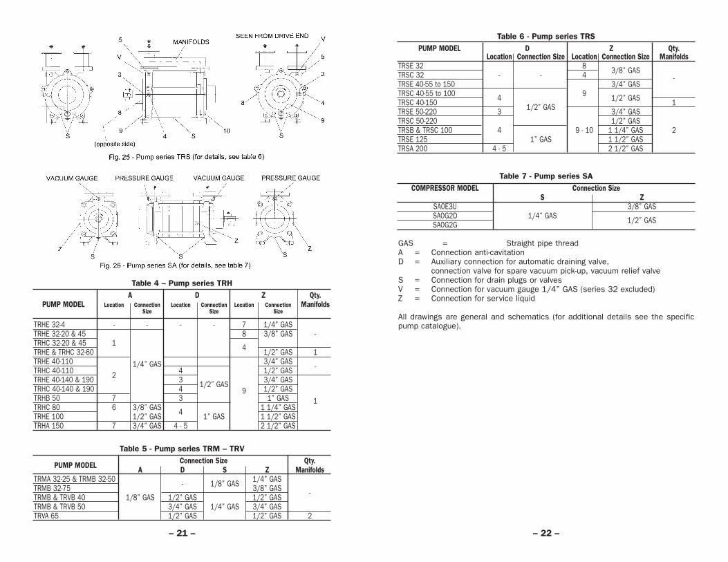
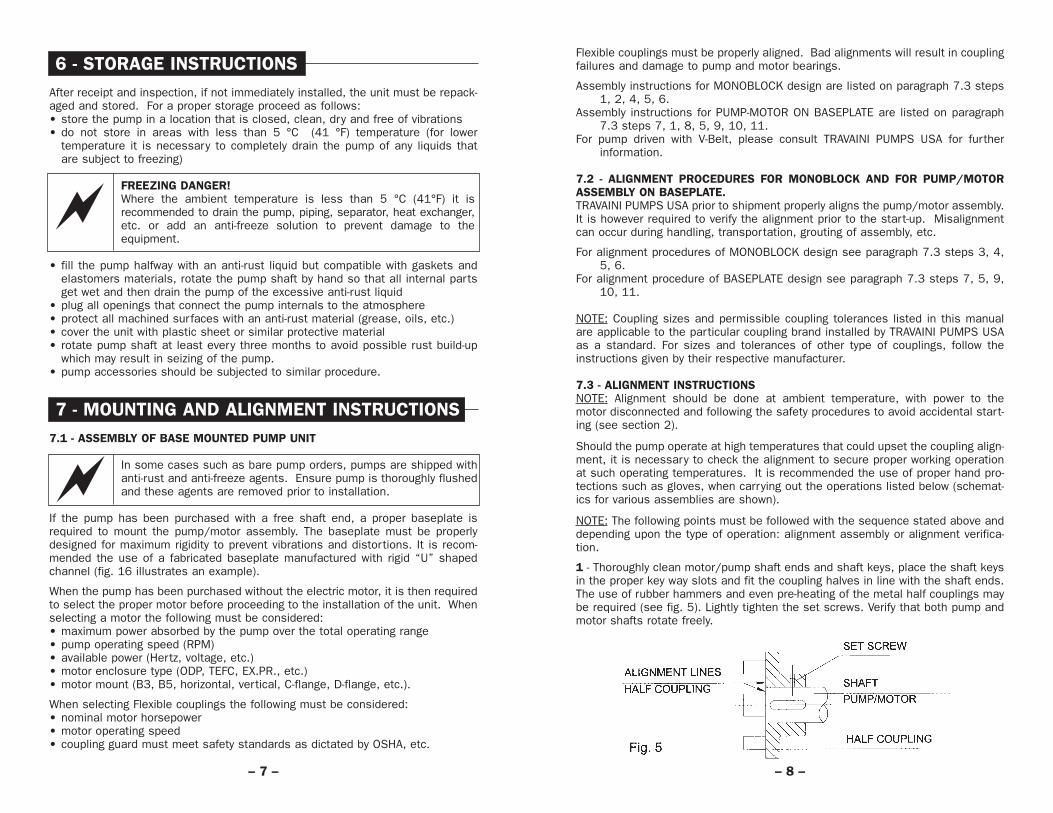
Table 6 - Pump series TRSPUMP MODEL D Z Qty.
Location Connection Size Location Connection Size ManifoldsTRSE 32 8 3/8” GASTRSC 32 - - 4 -TRSE 40-55 to 150 3/4” GASTRSC 40-55 to 100 4 9 1/2” GASTRSC 40-150 1/2” GAS 1TRSE 50-220 3 3/4” GASTRSC 50-220 1/2” GASTRSB & TRSC 100 4 9 - 10 1 1/4” GAS 2TRSE 125 1” GAS 1 1/2” GASTRSA 200 4 - 5 2 1/2” GAS
Table 7 - Pump series SACOMPRESSOR MODEL Connection Size
S ZSA0E3U 3/8” GASSA0G2D 1/4” GAS 1/2” GASSA0G2G
GAS = Straight pipe threadA = Connection anti-cavitation D = Auxiliary connection for automatic draining valve,
connection valve for spare vacuum pick-up, vacuum relief valveS = Connection for drain plugs or valvesV = Connection for vacuum gauge 1/4” GAS (series 32 excluded)Z = Connection for service liquid
All drawings are general and schematics (for additional details see the specificpump catalogue).
– 22 –
Table 4 – Pump series TRH
PUMP MODELA D Z Qty.
ManifoldsLocation Connection Location Connection Location ConnectionSize Size Size
TRHE 32-4 - - - - 7 1/4” GASTRHE 32-20 & 45 8 3/8” GAS -TRHC 32-20 & 45 1 4TRHE & TRHC 32-60 1/2” GAS 1TRHE 40-110 1/4” GAS 3/4” GAS -TRHC 40-110 2 4 1/2” GASTRHE 40-140 & 190 3 1/2” GAS 3/4” GASTRHC 40-140 & 190 4 9 1/2” GASTRHB 50 7 3 1” GAS 1TRHC 80 6 3/8” GAS 4 1 1/4” GASTRHE 100 1/2” GAS 1” GAS 1 1/2” GASTRHA 150 7 3/4” GAS 4 - 5 2 1/2” GAS
Table 5 - Pump series TRM – TRV
PUMP MODEL Connection Size Qty.A D S Z Manifolds
TRMA 32-25 & TRMB 32-50 - 1/8” GAS 1/4” GASTRMB 32-75 3/8” GAS -TRMB & TRVB 40 1/8” GAS 1/2” GAS 1/2” GASTRMB & TRVB 50 3/4” GAS 1/4” GAS 3/4” GASTRVA 65 1/2” GAS 1/2” GAS 2
– 21 –
Table 8 (continued)
dB(A) lbs. lbs. 50 Hz 60 Hz 50 Hz 60 HzTRMA 32-25 69 37 40 2900 3500 0.75 1.1TRMB 32-50 69 53 57 2900 3500 1.5 2.2TRMB 32-75 70 81 91 2900 3500 3 4TRMB 40-110 68 145 156 1450 1750 3 4TRMB 40-150 69 167 233 1450 1750 4 5.5TRMB 40-200 72 227 244 1450 1750 5.5 7.5TRMB 50-300 72 277 —- 1450 —- 7.5 —-
dB(A) lbs. lbs. lbs. 50 Hz 60 Hz 50 Hz 60 HzTRVB 40-110 68 —- 136 —- 1450 1750 3 4TRVB 40-150 69 —- 141 —- 1450 1750 4 5.5TRVB 40-200 72 —- 172 —- 1450 1750 5.5 7.5TRVB 50-300 72 —- 194 —- 1450 1750 7.5 10TRVA 65-300 70 293 341 354 1450 1750 7.5 10TRVA 65-450 70 321 387 442 1450 1750 11 15
dB(A) lbs. lbs. 50 Hz 60 Hz 50 Hz 60 Hz
SA0E3U 67 123 242 2900 3500 11 1515 20
SA0G2D 69 183 297 2900 3500 11 18,515 25
SA0G2G 69 191 139 2900 3500 15 20157 22 30
NOTES:• Noise level (measured at 3 feet distance, without motor, with pump installed in
the system) for pump series TRH, TRM, TRV when operating at 60 Torr andpump series TRS when operating at 175 Torr. Noise level test to ISO 3746standards and with pumps at 50 Hz operating speeds.
• Weights are for pumps fitted with Mechanical Seals and in Cast Iron materials(tolerance ± 10%).
• The assemblies, Monoblock and with Baseplate, are suitable for 50 Hz motors,except where otherwise noted. Indicated total weights for the assemblies arewithout motors.
• The installed motor size will cover the whole performance curve when operatingas vacuum pump.
– 24 –
9.12 - PUMP ENGINEERING DATATable 8
dB(A) lbs. lbs. lbs. 50 Hz 60 Hz 50 Hz 60 HzTRHE 32-4 67 30 42 70 1450 1750 0.55 0.75TRHC 32-20 66 55 68 90 2900 3500 1.1 1.5TRHE 32-20 66 40 50 75 2900 3500 1.1 1.5TRHC 32-45 66 62 75 97 2900 3500 1.5 2.0TRHE 32-45 66 46 56 81 2900 3500 1.5 2.0TRHC 32-60 66 66 79 103 2900 3500 2.2 3TRHE 32-60 66 57 68 95 2900 3500 2.2 3TRHC 40-110 65 147 174 202 1450 1750 4 5TRHE 40-110 65 108 134 160 1450 1750 4 5TRHC 40-140 65 174 194 262 1450 1750 4 5TRHE 40-140 65 147 167 220 1450 1750 4 5TRHC 40-190 65 191 231 301 1450 1750 5.5 7.5TRHE 40-190 65 165 205 260 1450 1750 5.5 7.5TRHB 50-280 70 286 321 429 1450 1750 9 15TRHB 50-340 70 308 374 466 1450 1750 11 15TRHB 50-420 71 319 392 484 1450 1750 15 20TRHC 80-600 76 484 539 792 1450 1750 22 30TRHC 80-750 76 528 616 829 1450 1750 30 40TRHE 100-870 79 906 —- 1263 960 1150 30 40TRHE 100-1260 79 1067 —- 1434 960 1150 37 50TRHE 100-1600 79 1140 —- 1518 960 1150 45 60TRHA 150-2000 83 2926 —- 3971 730 880 75 100TRHA 150-2600 84 3256 —- 4609 730 880 90 125TRHA 150-3100 84 3586 —- 4939 730 880 110 150
TRSC 32-20 69 42 55 85 2900 3500 1.1 1.5TRSE 32-20 69 32 45 68 2900 3500 1.1 1.5TRSC 32-50 69 44 58 89 2900 3500 1.5 2.0TRSE 32-50 69 38 47 73 2900 3500 1.5 2.0TRSC 40-55 66 119 147 73 1450 1750 2.2 3TRSE 40-55 66 75 103 130 1450 1750 2.2 3TRSC 40-80 66 125 154 180 1450 1750 3 5.0TRSE 40-80 66 81 110 136 1450 1750 3 5.0TRSC 40-100 67 132 158 187 1450 1750 3 5.0TRSE 40-100 67 86 114 141 1450 1750 3 5.0TRSC 40-150 67 156 194 211 1450 1750 4 5.0TRSE 40-150 67 97 125 152 1450 1750 4 5.0TRSC 50-220 67 191 229 268 1450 1750 5.5 7.5TRSE 50-220 67 162 202 240 1450 1750 5.5 7.5TRSC 100-550 76 440 495 719 1450 1750 15 20TRSC 100-700 76 506 561 836 1450 1750 18.5 30TRSB 100-980 78 550 638 847 1450 1750 30 40TRSE 125-1250 174 959 —- 596 960 1150 37 50TRSE 125-1550 174 1016 —- 634 960 1150 45 60TRSA 200-1950 183 2475 —- 1600 730 880 75 100TRSA 200-2500 184 2695 —- 1700 730 880 75 100TRSA 200-3100 184 2915 —- 1800 730 880 110 160
– 23 –
NoiseLevel
WeightBarePump
WeightassemblyMonoblock(B5 design)
Weightassembly
withbaseplate
OperatingSpeed
RPM
InstalledMotor Size
kWPUMPMODEL
NoiseLevel
WeightassemblyMonoblock
50 Hz motor
WeightassemblyMonoblock
60 Hz motor
OperatingSpeed
RPM
InstalledMotor Size
kWPUMPMODEL
NoiseLevel
WeightBarePump
WeightassemblyMonoblock(B5 design)
Weightassembly
withbaseplate
OperatingSpeed
RPM
InstalledMotor Size
kWPUMPMODEL
NoiseLevel
WeightassemblyMonoblock
50 Hz motor
WeightassemblyMonoblock
60 Hz motor
OperatingSpeed
RPM
InstalledMotor Size
kWPUMPMODEL

NOTE: See section 11.4 to 11.6 for OIL SEALED (DynaSeal™) systems start-up,operation and shut-down.
11.1 - START-UP of WATER SEALED Systems(In the following, reference is made to certain ITEM numbers, which appear on fig.17 to 22 of section 9 and 18).
Open valve at gas discharge if installed and partially open the valve at the suctionside. When operating the pump as a compressor, there must be a check valveITEM 2, fitted at the discharge side. When pump ITEM 4, is fitted in a partialrecovery or total recovery or WATER SEALED systems, as built by TRAVAINI PUMPSUSA, it is required to have drain valve ITEM 11, at separator ITEM 1, in the closedposition, flow regulating valve ITEM 13, in the open positions. Before start-up fillthe pump to the shaft centerline, separator and piping of system with service liq-uid through pump inlet flange or fill connection ITEM 28. Check all components forleakage. Start all accessories (temperature switches, level switches, pressureswitches, etc.) open cooling and flushing lines. Start the pump and open the serv-ice liquid valve, ITEM 3 if applicable, soon after, start the circulating pump, ITEM22 (if applicable) and adjust the service liquid flow (see table 3). Gradually openthe valve at gas suction side till the required vacuum level is reached. Check thesystem for abnormal conditions (see section 12 and 14). If the system is fittedwith a circulating pump and/or the service liquid has an excessive pressure theby-pass valve ITEM 13A, (if available) or valve, ITEM 13 can be adjusted to reducethe service liquid flow to the vacuum pump and/or optimize the thermodynamicefficiency of the heat exchanger ITEM 9.
NOTE: WATER SEALED systems engineered with multiple pumps are fitted with iso-lating valves at suction, discharge, and service liquid lines of each pump. Whenone or more pumps are not operating it is required to isolate the idle pump(s) byclosing these valves. When the pumps are put back into service the said valves(at suction and discharge) must be opened.
11.2 - OPERATIONAfter starting the vacuum pump check the following:• the vacuum level is as desired or adjust the flow-regulating valve to the required
vacuum• flow and temperature of service liquid and/or cooling liquid are as expected
(within 25% tolerance)• motor does not draw more amperage than shown on its nameplate• the pump-motor assembly does not have abnormal vibrations and noises such
as cavitation• the operating temperature at full load does not exceed approximately 85°C• there are no leaks from mechanical seals, joints and flushing or cooling liquid
lines• liquid level in separator is between the minimum and the maximum.
NEVER OPERATE THE PUMP DRY!
If the gas discharge is not open to the immediate atmosphere but it is piped toother locations, the pump discharge should be checked for back-pressures thatcould cause higher power consumption and loss of pump capacity.
– 26 –
10 - CHECK LIST PRIOR TO START-UPAll questions listed below must have POSITIVE answers prior toproceeding to the pump start-up. Please note that the following is a partial list. Special installations may require further precautions therefore; additional safety steps must be taken as the casedictates.
• This manual has been completely read, including the following chapters, andis understood in its entirety?
• The piping system has been flushed of any foreign particles, weldingimpurities, etc.?
• Have all piping and pump obstruction been removed?• All connections and piping are leak proof and there are no external forces or
moments applied to the piping or pump flanges?• Pump and motor are properly lubricated, per instructions?• Pump/motor alignment has been checked?• Mechanical seal flushing line has been connected, where required?• All valves in the installation are in the correct position?• All safety guards are in place?• Pump direction of rotation has been checked by jogging the motor?• The pump Stop switch is clear and visible?• Pump as well as installation are ready for start-up?
11 - STARTING, OPERATING ANDSTOPPING PROCEDURES
Upon receipt and/or completion of installation, before turning on the power to theelectric motor, rotate the pump shaft by hand to make sure that the pump rotor isfree. In the event the shaft does not turn, try to free the rotor by applying a torqueto the pump coupling with a pipe wrench. To free the rotor of a monoblock stylepump (without coupling) introduce a bolt (or similar tool) at the motor shaft endthat has a threaded connection and apply the torque by hand. In the event thepump does not become free with the above procedures, fill up the pump with asuitable solvent or lubricating liquid, let it rest for several hours to allow softeningof the rust build-up inside the pump, drain the pump and apply torque to the pumpshaft as described above to finally free the rotor.
NOTE: The selected solvent or lubricating fluid must be compatible with the pump,seals and gasketing materials.
CHECK PUMP-MOTOR COUPLING ALIGNMENT!This must be done prior to the first start-up and before every start-up if pump or motor has been removed from the installation formaintenance or other reasons. See section 7.2.
Prior to starting the pump verify that all auxiliary components are available, readyfor use and, where required, they are in the open position (i.e.: double mechani-cal seals are pressurized with buffer liquid, cooling liquid to heat exchanger isopen, etc.) and the pump bearings are lubricated. If the gas and/or service liquidtemperatures are in the dangerous levels, it is recommended to insulate thepump, piping and separator to avoid direct contact with their surface, avoidfreezing, thermal shock or loosing heat energy.
– 25 –

• the pressure gauge of the oil demister separator does not read more than 4 psi.When this value is exceeded, it will be required to change the filter element.
If the gas discharge is not open to the immediate atmosphere but it is piped toother locations, the pump discharge should be checked for back-pressures thatcould cause higher power consumption and loss of pump capacity.
11.6 - SHUT DOWN OF “OIL SEALED (DynaSealTM)” SYSTEMSClose, if applicable, the cooling water to the water/oil heat exchanger ITEM 9, thenturn off the power to the circulating pump ITEM 22. Where possible, graduallydecrease the vacuum level to 300-625 Torr in about 10 seconds max. The dis-charged service liquid from pump ITEM 4 helps producing a slow decelerationrather than sudden stop.Turn off motor ITEM 6, radiator ITEM 9 and any accessories and flushing circuitry.Make sure the non-return valves ITEM 2, or similar, at suction and discharge linesare leak tight. Should the system be idle for an extended period of time it is rec-ommended to disconnect the electricity to the motor panel, drain all liquids frompump, separator and piping. Refer to chapter 6 for storage procedures.
12 - OPERATING MAINTENANCEPeriodically check the working conditions of the system by means of the instru-mentation on the installation (pressure gauges, vacuum gauges, temperaturegauges, ampmeters, etc.) and that the pump is consistently handling the applica-tion for which it was selected. The operation of the pump should be without abnor-mal vibrations or noises, if any of these problems is noticed, the pump should bestopped immediately, search for the cause and make the necessary corrections.It is good practice to check the pump/motor alignment, the running conditions ofthe bearings and of the mechanical seals (see section 13) at least once a year,even if no abnormalities have been noticed. If there is a deterioration of the pumpperformance, which is not attributable to changes in system demands, the pumpmust be stopped and proceed with necessary repairs or replacement. If themechanical seals are fitted with external flushing and/or quenching lines theirpressures, temperatures and flows must be checked constantly.
NEVER ALLOW THE PUMP TO OPERATE IN THE CAVITATION AREA!
Cavitation has the characteristic metallic sound, like if gravel was rotating insidethe pump, and it causes also high pump vibrations. This happens when the pumpis running at absolute pressures close to the vapor pressure of the service liquidat the running conditions. This is a damaging condition for the impellers, portplates and casings. The cavitation causes erosion taking away metal particles andattacking the surface of the pump components. This is particularly damaging if thepump is handling corrosive gases, see chapter 14 for suggestions to correct theproblem.
Pump series TRH, TRM and TRV are fitted with an anti-cavitation valve that shouldbe left open (if required) see fig. 23 and 24 for the location. This valve should beconnected toward the upper part of the discharge separator so that, dependingupon the operating vacuum, the pump can either take air or discharge excessiveliquid. For OIL SEALED (DynaSeal™) systems the anti-cavitation valve ITEM 13His piped from pump ITEM 4 to the frame separator ITEM 1B.
– 28 –
11.3 - SHUT DOWN of “WATER SEALED” SYSTEMSFirst close the service liquid flow and cooling liquid flow (if applicable) then shutdown the circulating pump, ITEM 22, (if applicable). Where possible, graduallydecrease the vacuum level to 300-675 Torr in about 10 seconds max or, if com-pressor, decrease the discharge pressure. The discharged service liquid frompump, ITEM 4, helps produce a slow deceleration rather than sudden stop. Turnoff the power to motor ITEM 6 and close any accessories and flushing lines. Makesure the non-return valves, ITEM 2 or similar, at suction and discharge lines areleak tight. Should the system be idle for an extended period of time it is recom-mended to disconnect the electricity to the motor or control panel and drain all liq-uids from pump, separator and piping. Refer to chapter 6 for storage procedures.
11.4 – START-UP OF “OIL SEALED (DynaSealTM)” SYSTEMS(In the following, reference is made to certain ITEM numbers which are listed inthe figures and legend of section 12.1 and 19). Open the valve at the gas dis-charge, if applicable, and partially close the valve at the suction side. Close drain-ing valve ITEM 11, and valves for condensate recovery ITEMS 13F and 13L, whichare on the frame separator, ITEM 1B; open the valve ITEM 13D which is betweenthe circulating pump, ITEM 22, and the frame separator, ITEM 1B, then partiallyopen flow regulating valve, ITEM 13 between the discharge of circulating pump,ITEM 22 and the heat exchanger, ITEM 9, and the by-pass valve, ITEM 13A. If thesystem is fitted with a separator cyclone, ITEM 1D, and the adjacent collectingtank, ITEM 1E, it is required to close valves, ITEM 11A and 12 and open valveITEM 13E. Fill frame separator with service oil through the filling plugs ITEM 28.Proper oil level can be seen on sight glass ITEM 7. Refer to table 12 and 13 forthe required oil quantity. Start and/or open applicable accessories (temperatureswitches, level switches, etc.) and circuitry for cooling and flushing. Start vacu-um pump, ITEM 4, and soon after, start the circulating pump, ITEM 22. Adjust thecirculating pump capacity with valve ITEM 13. Gradually open the system suctionvalve till the desired vacuum is achieved. Check the systems for abnormal noisesor vibrations (see section 12 and 14). Adjust by-pass valve ITEM 13A, to regulatethe oil flow to the vacuum pump or to improve the thermodynamic efficiency of theheat exchanger.
NOTE: OIL SEALED (DynaSealTM) systems engineered with multiple pumps are fit-ted with isolating valves at suction, discharge, and service liquid lines of eachpump. When one or more pumps are not operating, it is required to isolate the idlepump(s) by closing these valves. When the pumps are put back into service thesaid valves (at suction and discharge) must be opened.
11.5 - OPERATION OF “OIL SEALED (DynaSealTM)” SYSTEMSAfter starting the vacuum pump check the following:• the vacuum level is as desired or adjust the flow-regulating valve to the required
vacuum• the oil temperature is between 140 and 175°F. If required, adjust the thermo-
stat on the radiator or in case of water/oil heat exchanger adjust the coolingwater flow
• motor does not draw more amperage than shown on its nameplate• the pump-motor assembly does not have abnormal vibrations or noises such as
cavitation• the surface temperature at full load, does not exceed approximately 85°F• that there are no leaks from mechanical seals, joints, flushing or cooling liquid
lines • liquid level in separator and pump is between the minimum and the maximum
– 27 –

installed at the housing, ITEM 2, will pro-vide an indication of the filter beingplugged; pressure reading over 4 psi.maybe an indication that the filter needsreplacement. At higher discharge pres-sures the discharged air quality willdecrease and the vacuum pumpabsorbed power will increase.
To replace the oil demister filter, simplydisconnect the oil scavenger line,remove the cover, ITEM 25, remove theused filter element, apply a gasketingmaterial over the gasket faces of thenew filter and place the latter in thehousing, put in place the cover and thescavenger line.
– 30 –
During operation it must be avoided to have sudden and frequent variations fromhigh to low vacuum. (e.g. suddenly opening the suction valve when the pump isoperating at pressures lower than 150 Torr). This would flood the pump creatinghigh power absorption that would put heavy stress on the motor and coupling.
Particular attention should be put on the quantity of the service liquid flow. Theflow will depend upon the type of installation (see section 9), the pump size,and/or the desired temperature rise. The flow of service water at 15 °C, for stan-dard pumps and normal operating conditions at various vacuum levels, is listedon the specific pump curves and/or on table 3 of section 9.7. Usually the tem-perature rise of service water, when handling dry air at 68 °F, is approximately 10°F. When condensable (e.g.: vapours) are present in the gas stream the heat loadto be removed by the service water will be higher, therefore the service water tem-perature rise will be higher. The service liquid flow and its temperature will affectthe pump performance. Generally the low service liquid flow will decrease thepump capacity, while a high service liquid flow will increase the absorbed powerby flooding the pump (see section 17 for information and calculations). Hard serv-ice water will generate lime build-up inside the pump. The severity of the depositwill vary with the water temperature. Lime or mineral deposits on the surface ofthe internal pump components will cause an increase of absorbed power, wear ofthe components and eventually will seize the pump. It is recommended to moni-tor the water hardness and, if too high, treat the water. If there are no alternatives,there should be periodical flushing of the pump with a solution that will removethe specific deposits, or the pump must be periodically disassembled, cleaned ofall incrustations and re-assembled. Systems with total service liquid recoveryrequire periodical change of the service liquid contained in the closed loop. Theheat exchanger must be kept well cleaned of all mineral deposits for an effectivethermodynamic heat exchange. During operation, a closed loop system will losesome of the service liquid, due to evaporation and/or saturation of the dischargedgases. It will be required to periodically make-up fresh liquid into the system. Thisoperation is not required for those systems that are fitted with a float type auto-matic make-up valve ITEM 8. This valve requires water at a pressure of approxi-mately 2 bar. Systems that handle condensable will experience a rise in the levelof the service liquid in the separator. The excessive liquid will be overflowedthrough the overflow valve or connection. If the specific gravity of the condensa-ble is higher than that of the service liquid, the condensable must be dischargedthrough the separator drain valve ITEM 11, preferably with system not running.
12.1 - “OIL SEALED (DynaSealTM)” SYSTEMS(For ITEM numbers refer to fig. 27 and it’s legend).
It is very important to keep the service oil temperature under control when the oiltemperature exceeds 90 °C there is the danger of seizing the pump and the gas-keting may start leaking.
Every 100 - 200 working hours it is suggested to check the oil level in the oil reser-voir, make-up oil if necessary and change the oil every 10,000 working hours(depending upon the use and the application).Those installations where the handled gases are contaminated with dust or sus-pended solids that can alter the oil characteristics will require more frequent oilcheck and changes.
Condensable vapors, if present during evacuation, can be flushed right through thedischarge of the separator (if they have low boiling point) or, when the system isidle, can be drained by opening valves, ITEM 16. During operation, the oil demis-ter filter will be impregnated with oil particles; the pressure gauge, ITEM 2,
– 29 –
TYPICAL BILL OF MATERIALS
Fig 27 (General Schematic Drawing)

Mechanical seals MUST NOT run dry! When seals are operated without lubricant and/or flushing liquid their faces and the elastomers may suffer damages beyond repair. It is suggested to check theconditions of the seal faces every approximately 4000 working hours.
Table 9
PUMP MODELBEARING MECHANICAL SEAL
Quantity Type Grease Quantity Quantity Diametereach bearing - gr. mm
TRHE 32-4 1 6302.2RSR 1 16TRHC and TRSC 32TRHE 32-20/45/60–TRSE 32 2 6304.2RSR 2 22
TRHE 40-110 – TRSE 40 6305.2RSR
TRMA 32-25 1 6304.2RSR 281 6204.2RSR
TRMB 32-50 1 6305.2RSR1 6205.2RSR 24
TRMB 32-75 1 6306.2RSR1 6206.2RSR 1 28
TRMB 40-110 1 3208.2RSR —-1 6206.2RSR
TRMB 40-150 1 3208.2RSR 351 6306.2RSR
TRVB 40-110/150 2 6208.2RSR
TRMB 40-200 and 50-300 1 3210.2RSR1 6308.2RSR 45
TRVB 40-200 and 50-3001 6210.2RSR1 6208.2RSR
TRHC and TRSC 40TRHE 40-140/190 2 6306.2RSR 35TRSC and TRSE 50TRHB 50 - TRVA 50 and 65 6308 20 43TRHB/C 80 - TRSB/C 100 6310 35 2 55
TRHE 100 - TRSE 125 1 63141 NU 314 50 75
TRHA 150 - TRSA 200 2 7320B.MB.UA1 22320ES.TVPB.C3 180 110
NOTE: The supplied data are for pumps in STANDARD construction. For specialconstruction please contact TRAVAINI PUMPS USA.
– 32 –
13 - BEARINGS AND MECHANICALSEALS MAINTENANCE
WARNING: The maintenance must be carried out with the pump turned off andthe electrical power, or other driving mechanism, must be disconnected. Thepower should only be turned back on by the same person doing the mainte-nance. It is, however, recommended to have at least a team of two workersdoing the maintenance and the supervisors should be fully aware of the work inprogress.
CAREFULLY FOLLOW THE SAFETY PROCEDURES LISTED INCHAPTER 2.
13.1 - BEARINGSAt assembly time the pump bearings are lubricated with quality grease (sealedbearings are greased for life). Some of the recommended greases are:
BP - ENERGREASE LS - EP 2 MOBIL - MOBILUX EP 2EXXON - BEACON EP 2 SHELL - SHELL ALVANIA EP GREASER
Bearings for pumps working in standard conditions should be lubricated every2000/2500 working hours with a quality grease (see “Disassembly & Assembly”for the replacement of bearings). Bearing temperature should not exceed the 85°C during normal working conditions and normal environments. Bearings can over-heat for reasons such as too much grease, misalignment of flexible coupling,wrong bearings, excessive vibrations, bearing wear. See tab. 9 for bearing num-bers and type used for each pump.
13.2 - MECHANICAL SEALSMechanical seals can be with manytypes of materials, design and installa-tions (see fig. 28). TRAVAINI PUMPS USAhas evaluated their selection at the timeof pump design; it is a function of thefluid and working conditions. The sealsare supplied with the proper flow of liquidfor their lubrication, through internalpump passages. Upon request, thepump can be provided with seal lubrica-tion coming from an outside source; theset-up must be such that the seals areguaranteed the liquid quantity and pres-sure as recommended by TRAVAINIPUMPS USA or by the seal manufacturer.For mechanical seal shaft size see table 9.Mechanical seals normally fitted in the vacuum pumps are to DIN 24960standards. See “Disassembly & Assembly Instructions” for major seal dimen-sions. Normally mechanical seals do not require maintenance until there is avisible liquid loss (leakage). See “Disassembly & Assembly Instructions” for sealreplacement.
– 31 –

CAUSES SOLUTIONS14 Inadequate seal lubrication Check flushing liquid temperature, flow and
pressure15 Mineral deposits from hard Clean the pump
water16 Foreign particles in pump Disassemble the pump to remove the foreign
objects (see “Disassembly & Assembly Instructions”)
17 Low suction pressure Open the vacuum regulating valve and/or the anti-cavitation valve (vacuum relief valve)
18 Wrong pump rotation Reverse the rotation (see section 8)19 Bad gaskets Replace the defective gaskets (see the
“Disassembly & Assembly Instructions”)20 Wrong motor connections Check the electrical connections (connectors,
fuses, breakers) and the power supply line (see section 8)
21 Pump seized Disassemble and repair the pump (see “Disassembly & Assembly Instructions”)
22 Pump undersized Select a pump with higher capacity23 Pump worn-out Disassemble and repair the pump (see
“Disassembly & Assembly Instructions”)24 Excessive liquid flow Reduce the liquid flow through the pump suction;
through suction line install a centrifugal separator (cyclone) before the pump
25 Instrumentation out of Check the working characteristics, replacecalibration if required
15 - REPAIRING AND REMOVINGPUMP FROM THE INSTALLATION
Should there be the need for pump repair a knowledge of the specific“Disassembly and Assembly Instructions” is required.
FOLLOW THE SAFETY PRECAUTION MEASURES OUTLINED IN CHAPTER 2.
Before working on the pump it is important to:• procure and wear the proper safety equipment (hard hat, safety glasses, gloves,
safety shoes, etc.)• disconnect the electrical power supply and, if required, disconnect the electrical
cable from the motor• close the isolating valves at pump inlet, outlet and service liquid• let the pump cool down to ambient temperature if it has been handling hot fluids• adopt safety measures if the pump has been handling hazardous liquids• drain the pump internals of the pumped liquid through the draining connections,
if necessary rinse with neutral liquid.
To remove the pump and the motor from the installation proceed as follows:• remove bolts from pump suction and discharge flanges• remove the coupling guard• remove the spacer of the coupling, if there is one
– 34 –
14 - TROUBLE SHOOTING: PROBLEMS,CAUSES AND SOLUTIONS
Consult the following table when problems are experienced, if solutions are notfound in this chart or should there be any doubts; do not hesitate to contactTRAVAINI PUMPS USA or your local distributor.
Table 10 - LIST OF PROBLEMSPROBLEM LIST OF POSSIBLE CAUSESPump does not create or the 1 - 2 - 3 - 4 - 9 - 11 - 18 - 19 – 22 - 23 - 24 - 25vacuum is too lowExcessive noise 1 - 4 - 5 - 6 - 7 - 10 – 24High power consumption 1 - 5 - 6 - 8 - 9 - 15 - 24 – 25Vibration 5 - 6 - 7 - 8 - 10 - 12 - 13 – 24Mechanical seal leaking 11 – 14Pump looses liquid 11 – 19 - 23Bearing failure 5 - 6 – 7Pump does not start 1 - 6 – 20 - 21Shaft partially or totally locked 6 - 10 - 15 - 16 - 21Cavitation 3 - 4 – 8 - 9 - 17 - 24
CAUSES SOLUTIONS1 Defective motor or Check the voltage, the frequency, motor type,
wired wrong power consumption, rotation, wiring connections, phase consistency
2 Leakage in suction piping Repair piping; check valves for leakage3 Service liquid high Lower the service liquid temperature;
temperature check the level of the service liquid; adjust the cooling liquid flow; adjust the radiator thermostat to lower temperature setting
4 Low service liquid flow Increase the service liquid flow5 Coupling misalignment Re-align the coupling and the pump/motor
assembly (see cap. 7)6 Faulty bearing Replace the bearing(see “Disassembly &
Assembly Instructions”)7 Cavitation Open the anti-cavitation valve or set the relief
valve to a lower vacuum (see table 4 to 6)8 High service liquid flow Reduce the service liquid flow; adjust the by-
pass valve9 High back pressure Check the discharge line for obstructions or high
friction losses; reduce the back-pressure tomaximum 0.1 bar
10 Wrong pump/motor Verify that the base surface is level and that allassembly pump feet are resting on the surface,
add spacers if required (see section 11)11 Mechanical seal failure Change the mechanical seal (see “Disassembly
& Assembly Instructions”)12 Wrong pump mounting Remount the pump (see section 7)13 Piping weight resting Support the piping with hangers or other means
on pump (see section 11)
– 33 –

– 36 –
17 - ENGINEERING DATA17.1 - INFLUENCE OF SERVICE LIQUID TEMPERATURE, SPECIFIC GRAVITYAND VISCOSITY ON PUMP PERFORMANCEThe performance of liquid ring vacuum pumps is based on the use of water at 15°C as service liquid. With water at different temperatures the pump capacity andthe maximum attainable vacuum level will vary as a function of the type of pump,as illustrated by the curve sets of fig. 29 and 30.
EXAMPLE: Pressure = 45 Torr - Water temperature = 24°C - Pump series TRH -Capacity (15°C water) = 310 ACFM From curves of fig. 30 we find the correctingfactor of 0.80, therefore the actual capacity for the pump at the given conditionswill be: 310 x 0.80 = 248 ACFM. The maximum suction pressure before incur-ring cavitation will be approximately 35 Torr.
Regarding the performance variation due to changes of specific gravity and vis-cosity, it can be assumed a proportional variation in power consumption however;the changes in capacity at different pressures must be analyzed case by case.Please refer the conditions to TRAVAINI PUMPS USA when these corrections areneeded.
• if required, remove the motor anchor bolts on the baseplate, for base mountedassembly, or the bolts on the adapter flange in the case of monoblock design
• remove the pump anchor bolts on the baseplate• remove the pump from the installation. Avoid damaging other system compo-
nents.
After pump repairs, re-install following the steps from “Assembly and Alignment”procedures and after (see the applicable chapters).
16 - SPARE PARTSWhen ordering the pump it is good practice to also order the necessary spareparts, especially when there are no stand-by pumps in the installation. This willminimize unnecessary down times in the event of pump failure or routine mainte-nance.
It is therefore, recommended to stock the following spare parts for each pumpsize:
(1) Impeller set(1) Complete shaft assembly(1) Bearing set(1) Mechanical seal set (or packing set)(1) Gasket sets(1) Radial seal ring set(1) Bearing spacer set(1) Coupling rubber insert set
For better parts management, the VDMA 24296 standards suggest to stock thenumber of parts as a function of the number of pumps being used in the plant.On the pump nameplate are printed pump model, year of manufacture and pumpserial number. When ordering spare parts always provide this information. Pumptype, parts item number (VDMA) and description as per the pump sectional draw-ing and parts list is useful information that helps to supply correct spare parts foryour pump. We recommend the use of original spares: in case this is not respect-ed, TRAVAINI PUMPS USA declines any responsibility for eventual damages andnot correct running caused by not original spare parts.
– 35 –

17.3 - OPERATION WITH PARTIAL RECOVERY OF SERVICE LIQUIDWhere the working conditions will allow it, the service liquid temperature can beincreased utilizing a smaller quantity of fresh liquid from an outside source. Asimilar flow as the make-up is discharged to the drain while the balance of liquidrequired by the pump is recirculated. In these cases the service liquid workingtemperature rises and the pump capacity will require correction per curves of fig.29 and 30. The system installation will be similar to the schematic of fig. 31.Depending upon the affordable loss of capacity the service liquid temperature T2may be set and the make-up flow of fresh liquid QF can then be calculated:
QF(m3/h) =
QA • ∆TT2 - T1 + ∆T
Where:QF = Fresh make-up flow from outside source in m3/hQA = Total service liquid flow required for the operating
conditions in m3/h∆T = Service liquid temperature rise (see section 17.2)T2 = Service liquid temperature to pumpT1 = Temperature of make-up liquidThe fig. 31 indicates a generic schematic of a liquid ring vacuum pump in a par-tial recovery system. By closing the recirculation line the system would become a“once through” installation where all the service liquid is drained, therefore:
QA = QF and T2 = T1
– 38 –
17.2 - SERVICE LIQUID TEMPERATURE CHANGE ACROSS THE PUMPThe service liquid of a liquid ring pump absorbs total heat QT as follows:
QT (BTU) = Qc + QK + QRWhere:Qc = 0.9 x BHP x 2545 = Isothermal compression heatQK = mV x r = Condensation heatQR = mg x cp x ∆Ta = Cooling heat (Generally negligible,
ignored in calculation of QT)
mV = mass condensed incoming vapor in PPHmg = mass incoming gas in PPHP = absorbed power at operating point in kWcp = gas specific heat in BTU/1B/°Fr = heat of vaporization in BTU’s∆Ta = differential temperature in R, between incoming gas TG and service
liquid discharge temperature (T2 + ∆T)K = Kelvin temperature
Once the QT is known it is possible to calculate the differential temperature ∆T ofthe pump service liquid:
∆T =QT
QA•ρ•cP
Where:QT = total heat load before calculated in BTU/hourQA = pump service liquid flow in GPMρ = service liquid density in kg/m3 (water = 1.0)cP = service liquid specific heat
NOTE: It can be assumed that the discharge gas and service liquid have sametemperature.
– 37 –

18 - ENGINEERING DATA FOR“WATER SEALED” SYSTEMS
WORKING PRINCIPLEThe WATER SEALED packages main com-ponents are: a liquid ring vacuum pumpITEM 21 from series TRH, TRS, TRM,TRV, an air/liquid separator reservoirITEM 19, a heat exchanger ITEM 7, allmounted on a common base. When oper-ating the vacuum pump discharges fromthe discharge port the gas handled with aportion of the liquid from the pump inter-nal liquid ring. This liquid must be contin-uously returned to the pump.
17.4 - UNIT CONVERSION TABLE
– 39 –
Absolute Pressure Vacuum
Dry
air f
low
at
15°
C
Sat
urat
ed v
apou
r flo
w
Sat
urat
ed w
ater
tem
pera
ture
Vapo
riza
tion
hea
t
FIG. 32a PARTIAL RECOVERY System
FIG. 32 FULL RECOVERY System
TYPICAL BILL OF MATERIALS
– 40 –

The gas/liquid mixture is separated in a cylindrical tank (separator), the gas isvented through the top mounted discharge flange of the separator and the liquidis collected at the bottom of the separator ready to be returned to the vacuumpump.
During the suction and compression cycle of the vacuum pump, all the energy istransformed into heat energy and almost all of it is absorbed by the service liquid.Therefore the liquid must be cooled prior to be returned to the pump, either witha heat exchanger (total recovery system) or with the addition of cool make-up liq-uid (partial recovery system).
The FULL RECOVERY system (see fig. 32 and legend) does not require an appre-ciable flow of make-up from an external source but only the necessary amount tocompensate for the liquid lost due to evaporation, with the discharged gases.
The heat exchanger sizing should be based on using a minimum amount of cool-ing liquid (usually water) to keep the service liquid at the ideal temperature for thebest efficiency of the vacuum pump. Remember the higher the temperature of theservice liquid the higher the losses in pump capacity and maximum vacuum seesection 17.
This system is particular suitable where the service liquid and the condensedgases cannot be discharged to the environment, either for pollution reasons orbecause the fluids are too valuable.
The PARTIAL RECOVERY system (see fig. 32a and legend) requires a constantflow of cold make-up liquid from an external source. This liquid must be of thesame nature as the service liquid being used by the pump. The mixture of themake-up and the service liquid being discharged by the pump, will have a constanttemperature when enters the vacuum pump service liquid connection.
The same amount of service liquid taken from the outside source must be over-flowed through the separator overflow connection situated at the pump shaft cen-terline. This system is utilized in many applications for conditions where there isintermittent use, or low vacuum levels, or there is no danger of pollution and theliquid can easily be drained.
Furthermore, this may prove to be the only alternative to the total recovery sys-tem for those installations where the cooling liquid is not available or it is toowarm. Numerous accessories are available to meet the customers’ requests andsuitable for the installation, process and maintenance. For materials of con-struction and some engineering data see table 11 and 12.
Table 11 - STANDARD MATERIALS FOR “WATER SEALED” SYSTEMSCOMPONENT MATERIAL DESIGN
Vacuum pump GH - F - RA - RZ A3Separator reservoir Carbon steel AISI 316 SSBaseplateHeat Plates Carbon SteelExchanger Gaskets Nitrile rubber / VitonPiping Carbon steel AISI 316 SSValves - Thermometer BrassLevel gauge Polycarbonate “Pirex” Glass
For vacuum pump materials (GH - F - RA - RZ - A3) see section 4.
Table 12 - GENERAL AND NOT BINDING ENGINEERING DETAILSFOR “WATER SEALED” and “OIL SEALED (DynaSeal™)” SYSTEMS
WATER SEALED 2 5HP 300 450OIL SEALED 2 poles / 60 HzWATER SEALED 3 5HP 400 800OIL SEALED 4 poles / 60 HzWATER SEALED 4 10HP 1000 1000OIL SEALED 4 poles / 60 HzWATER SEALED 5 20HP 1200 1500OIL SEALED 4 poles / 60 HzWATER SEALED 6 40HP 1800 2000OIL SEALED 4 poles / 60 HzWATER SEALED 7 60HP 2500 3500OIL SEALED 6 poles / 60 Hz
EXAMPLE OF “WATER SEALED” SYSTEM General Schematic and Accessories or Options
– 42 –– 41 –
PACKAGESERIES
Motor SizeDry weight lbs.
WATERSEALED
OIL SEALED(DynaSealTM))
LEGEND

LEGEND
– 44 –– 43 –
20 - PRODUCT DATA INFORMATION FORM
COMMENTS ________________________________________________________________
__________________________________________________________________________
__________________________________________________________________________
__________________________________________________________________________
__________________________________________________________________________
__________________________________________________________________________
__________________________________________________________________________
__________________________________________________________________________
__________________________________________________________________________
__________________________________________________________________________
__________________________________________________________________________
__________________________________________________________________________
19 - ENGINEERING DATA FOR“OIL SEALED (DynaSealTM)” SYSTEMS
WORKING PRINCIPLEOIL SEALED (DynaSeal™) packages main components are: a liquid ring vacuumpump, ITEM 4, from series TRH, TRS, TRM, TRV, an air/liquid separator reservoir,ITEM 1A, a heat exchanger ITEM 9 and an oil demister filter, ITEM 1B.
Turbine type mineral oil, or equal, is used for service liquid. The characteristics ofthe chosen oil are such that at pressures below 75 Torr, the pump capacity isgreater than what would be when using water, and higher vacuum levels are attain-able. When operating, the vacuum pump discharges the gas handled with a por-tion of the liquid in tank, ITEM 15, that acts as separator of gas from the oil andlet settle any condensable or particles coming through the pump suction flange.The circulator pump, ITEM 26, pumps the oil back to the vacuum pump after it hasbeen through the heat exchanger, ITEM 10, and cooled at about 140-180 ∞F. Thegas is vented after being cleaned of all oil with the special oil demister element;a pressure gauge, ITEM 2, on the filter housing, ITEM 5, gives indication of thedegree of dirt contained by the filter element. Contrary to rotary vane vacuumpumps, there are no moving parts that come in contact with each other, thereforethere is no need for lubrication of the pump internals; these are very robust andreliable pump packages which offer extended operating life even when handlingcondensable gases. See table 14 for materials of construction and table 12 inchapter 18 for some engineering data.
Table 14 - STANDARD MATERIALS FOR “OIL SEALED (DynaSealTM)” SYSTEMSCOMPONENT MATERIAL DESIGN
Vacuum pump GH - F - RA - RZBaseplate Carbon steel
Heat exchanger Cooler core Aluminium
air-oil Shroud Carbon steelFan - Guard Carbon steel-Plastic coated
Piping Carbon steel -Carburite rubberValves - Thermometer BrassLevel gauge Polycarbonate
See section 4 for vacuum pump materials of construction (GH-F-RA-RZ).

CONFIDENTIAL PRICE LIST PTTP # 01-07
Date of issue: January 01, 2007; Supersedes any earlier issues; Warranty, Terms & Conditions
Subject to the terms and conditions hereof, Travaini Pumps U.S.A., Inc. (hereafter referred to as the “Company”) warrants that the products and parts of its manufacture specified below, when shipped, and its services when performed, will be free from defects in material and workmanship for following warranty time periods:
PRODUCT DESCRIPTION WARRANTY PERIOD FROM DATE OF SHIPMENT
Liquid Ring Vacuum Pump system or pump products
Two (2) years
Rotary vane system or pump products
24 / 18 months if TPUSA oil used / not used
Centrifugal pump products 18 months, or 12 months from date of installation, whichever occurs first
Mechanical seals 3 months Repaired pumps / systems 6 months for the repair / work performed
This Warranty shall apply to liquid ring vacuum products only if they are operated with Company approved seal fluids and to rotary vane products only if they are operated with Company approved lubricants. In-warranty repaired or replaced products are warranted only for the remaining unexpired portion of the warranty period applicable to the repaired or replaced product(s). This Warranty does not extend to equipment such as electric motors, starters, heat exchangers and other accessories furnished to the Company by third party manufacturers and/or suppliers. Said accessories are warranted only to the extent of any warranty extended to the Company by such third party manufacturers and/or suppliers. Replacement of maintenance items, including, in particular, seals, bearings, filters, etc. supplied in connection with standard maintenance service provided by the Company are not covered by this Warranty. Any technical assistance, advice, or comments provided by the Company regarding system components, other than those manufactured by the Company, are not covered under this Warranty; the Company disclaims any liability in connection with same. The Company disclaims any liability in connection with the malfunctioning of any system(s) or component(s) of system(s) which conform to designs, specifications and/or instructions mandated by purchasers. This Warranty is limited exclusively to products and/or parts of the Company properly installed, serviced and maintained in full compliance with the Operating and Maintenance manual of the Company. This Warranty shall not extend to products and/or parts which
TRAVAINI PUMPS USA WARRANTY
have been misused or neglected or not used for the purpose(s) for which they were intended, including, in particular, products operated at/in excessive temperature or dirty environments, products used in conjunction with corrosive, erosive or explosive liquids or gasses, and/or products malfunctioning as a result of build-up of material in the internal parts thereof. Products which are disassembled without the prior written consent of the Company and/or which are repaired, modified, altered or otherwise tampered with in any manner inconsistent with the Operating and Maintenance manual of the Company are not covered under this Warranty. Products and/or parts which are kept in “long term” storage, as such terms are defined in the Operations & Maintenance manual of the Company, and not maintained in accordance with Company long term care procedures specified by the Company are not covered under this Warranty. Warranty claims must be made within the warranty period specified above for each of the Company’s products and services and include the serial number thereof. The Company’s obligations under this Warranty are limited, in the Company’s sole discretion, to repair, replacement or refund of the purchase price received by the Company for the product, part or service. Notwithstanding the foregoing, the Company shall have the option to provide alternative solutions of a different design. In no event shall the purchaser and/or any subsequent owner or beneficiary of the products, parts and/or services be entitled to recover incidental, special or consequential damages arising out of the breach of this Warranty or any defect, failure or malfunction of the products and/or services supplied by the Company. A written return authorization must be obtained from the Company prior to the return of any product and/or part under this Warranty. Products and parts are to be returned only to the Company’s facilities or such facilities as the Company may designate in writing. Costs of uninstalling/ reinstalling the product and/or any part under Warranty, as well as all costs associated with the shipment thereof to and from the facilities of the Company shall be at the owner’s sole expense. THIS WARRANTY AND THE COMPANY’S OBLIGATIONS HEREUNDER ARE EXPRESSLY IN LIEU OF ALL OTHER WARRANTIES, INCLUDING BUT NOT LIMITED TO IMPLIED WARRANTIES OF MERCHANTABILITY AND FITNESS FOR A PARTICULAR PURPOSE. ALL WARRANTIES WHICH EXCEED THE AFOREMENTIONED OBLIGATIONS ARE HEREBY DISCLAIMED BY THE COMPANY AND EXCLUDED FROM THIS WARRANTY, WHETHER BASED ON CONTRACT, WARRANTY, NEGLIGENCE, INDEMNITY, STRICT LIABILITY OR OTHERWISE. NO EMPLOYEE OF THE COMPANY OR OTHER PERSON IS AUTHORIZED TO GIVE ANY OTHER WARRANTY OR TO ASSUME ANY OTHER LIABILITY ON THE COMPANY’S BEHALF. Effective as of January 2007