Embed Size (px)
Citation preview

INTERNATIONAL MACHIINE CONCEPTS
1
Operation Manual of IMCL-500 Type Vertical
Automatic Packing Machine

INTERNATIONAL MACHIINE CONCEPTS
2
I. Technical parameters
IMCL-500 Vertical-bag automatic liquid packaging machine adopts pneumatic drive,
PLC control and touch screen man-machine interface, can automatically complete the
whole packaging process, including bag making, capping, filling and measuring,
sealing and cutting, date printing and finished product output. During the packaging
process, the photoelectric calibration device will be used to ensure the integrity of the
pattern of packaging bags.
This machine has reasonable structure design, beautiful model, reliable working,
accurate measurement, and easy to operation, adjustment and maintenance. It is
applicable to the packaging of various non-carbonic beverages, fruit juice, wine
(alcohol content is less than 60°), edible oil, vinegar, sauce and drinking water, and
viscous materials, such as jams, spices and detergents having certain liquidity.
The technical parameters of this machine are as follows:
Production capacity: 15~30bags/min
Air consumption: 0.4m3/min (0.8MPa)
Packaging capacity: 150~1200ml (need to replace the fittings)
Power supply voltage: AC220±10%V 50Hz
Measuring accuracy: ±1.5%
Whole machine power: maximum 4.0kw, normal work 2.0kw
Film width: 400~650(mm)
Machine weight: 650kg
Working pressure: 0.65MPa
Appearance size: 1950!1200!2500(mm)
Film thickness: 0.10~0.14(mm)

INTERNATIONAL MACHIINE CONCEPTS
3
Structure introduction of vertical-bag automatic liquid packaging machine

INTERNATIONAL MACHIINE CONCEPTS
4
1. 传送带 —Conveyer belt 2. 横封切断机构 —Horizontal sealing shutdown mechanism 3. 膜牵引机构 —Film traction mechanism 4. 纵封机构 —Vertical sealing mechanism 5. 操作箱 —Operating box 6. 纵封高度调节机构 —Vertical sealing height adjusting mechanism 7. 袋折叠机构 —Bag folding mechanism 8. 电器箱 —Electric appliance box 9. 供料机构 —Product feeding mechanism 10. 供膜机构 —Film supplying mechanism 11. 打孔机 —Hole-punching machine 12. 下料管 —Discharge pipe
Figure 1 Structure diagram of packaging machine

INTERNATIONAL MACHIINE CONCEPTS
5
II. Performance introduction and adjustment methods of each part
1. Composition of the whole machine
The machine consists of one main unit (packaging machine) and one belt conveyer
(see the above Figure 1).
2. Introduction and adjustment of the main mechanism of packaging machine Note: if the operations or adjustments mentioned below relate to the dangerous
places, they only can be carried out after stopping the machine and pressing the
emergency stop button.
2.1 Conveyer belt
The conveyer belt of this machine is driven by the independent motor and
reducer, and its startup and shutdown are controlled by the button of
“conveyer belt” on the touch screen.

INTERNATIONAL MACHIINE CONCEPTS
6
1. Drive motor
2. Drive roller
3. Belt
4. Driven roller
5. Driven shaft
6. Tension adjusting screw
7. Operating slide
8. Rear support
9. Height adjusting nut
10. Front support
Figure 2 Conveyer belt
As shown in Figure 2, rotate two tension adjusting screws 6 of the rear end, can adjust
the tightness of the belt to balance the tension on both sides of belt; rotate the height
adjusting nut 9, can change the height of the rear end of conveyer belt, and adjust to the
appropriate height (under the normal working condition, the distance from belt to
packaging bags is 20-30mm), then lock two nuts.

INTERNATIONAL MACHIINE CONCEPTS
7
2.2 Horizontal sealing shutdown mechanism
The mechanism consists of heat sealing, cold pressing part, shutdown part and
servo lifting part. During the packaging process, it will complete the sealing,
smashing, cutting-off and film tracking on both sides of packaging bags. The
structure composition is shown in Figure 3.

INTERNATIONAL MACHIINE CONCEPTS
8
1. Servo motor
2. Cold pressing cylinder
3. Horizontal sealing cylinder
4. Litter
5. Horizontal sealing back
6. Horizontal sealing head
7. Pressure adjusting screw
8. Shutdown cylinder
9. Cold pressing head
10. Blade
11. Cold pressing back
12. Pressure adjusting nut
13. Lifting crank
14. Lifting connecting rod
15. Connecting rod nut

INTERNATIONAL MACHIINE CONCEPTS
9
Figure 3 Horizontal sealing shutdown mechanisms
2.2.1 If the seal doesn’t fit due to the unbalance pressure of horizontal sealing
head, it can adjust the pressure of head ends and middle part through five
pressure adjusting screws 7, make them balance, and then lock the nuts
after the completion of adjustment. The five screws will not change the
sealing head pressure, but can distribute the force of the cylinder on the
whole sealing head uniformly.
2.2.2 If the width of both seal sides of packaging bags is different significantly, it
can change the height of horizontal sealing back 5 and horizontal sealing
head 6, until no significant difference of width on both seal sides.
Horizontal sealing back 5 and horizontal sealing head 6 shall be aligned
with each other during the adjustment process.
2.2.3 Adjust the pressure adjusting nut 12, can make the balance of cold sealing
pressure.
2.2.4 Blade 10 is the part need to be replaced appropriately according to the
service condition, and the replacement method is shown below: put inner
hexagonal wrench in the slot hole at the right lower end of cold sealing
pressure head (facing machine), loosen the screws of two clamp blades,
remove the blade, plug the new blade into the original position and then
lock the screw. The angle between the cutter edge and the plane of sealing
head shall be between 135° to 160°, and the knifepoint is revealed 2-3 mm
above the plane.
2.2.5 Usually check whether the nut on both ends of lifting connecting rod 14 is
loose, and timely fasten.
2.3 Vertical sealing mechanism
Vertical sealing mechanism consists of bag top opening sealing part and
bag bottom sealing part, as shown in Figure 4.

INTERNATIONAL MACHIINE CONCEPTS
10
1. Vertical sealing cylinder
2. Fastening handle
3. Bag bottom sealing back
4. Bag bottom sealing head
5. Bag opening sealing back
6. Bag opening sealing head
7. Pressure adjusting screw
Figure 4 Vertical sealing mechanism
2.3.1 Loosen the fastening handle 2, can move the corresponding sealing back or
sealing head to the right and left sides, and realize the changes for arc
height of bag bottom or width of upper seal.
2.3.2 Adjust four pressure adjusting screws 7 to balance the sealing head pressure
of bag bottom.
2.4 Vertical sealing height adjusting mechanism (Figure 5)

INTERNATIONAL MACHIINE CONCEPTS
11
1. Vertical sealing height adjusting hand wheel
2. Fastening hand wheel
3. Vertical sealing adjusting screw
4. Vertical sealing link block
Figure 5 Vertical sealing height adjusting mechanism
Two vertical sealing height adjusting hand wheels 1 can adjust the height of
vertical sealing mechanism to align with the sealing position of bag bottom.
Loosen the fastening hand wheel 2, rotate the vertical sealing adjusting hand wheel
1, and then lock the fastening hand wheel 2 after completing the adjustment.
2.5 Bag folding shaping mechanism (Figure 6)

INTERNATIONAL MACHIINE CONCEPTS
12
1. Set square
2. Film guiding roller
3. Bag bottom folding support
Figure 6 Bag folding shaping mechanism
The positions of set square 1 and four film guiding rollers 2 have been adjusted
before leaving the factory, without adjustment in the work. Bag bottom folding
support 3 plays a role of assisting bag shaping, and can change the folding depth
of bag bottom to some extent; loosen the fastening screw, and can rotate up and
down, to make it fold to the appropriate depth, but do not rise too tight, otherwise
it is easy to scratch the packaging film.
2.6 Product feeding mechanism
The machine adopts the quantitative product feeding device composed by
pneumatic piston measuring cylinder and double one-way valve, with adjustable
packaging capacity and high measuring accuracy. As shown in Figure 7

INTERNATIONAL MACHIINE CONCEPTS
13
1. Feed pipe
2. Discharge pipe
3. One-way valve
4. Product feeding cylinder barrel
5. Piston
6. Product feeding cylinder
7. Measuring adjusting nut
8. Locking nut
Figure 7 Product feeding mechanism
2.6.1 After each cleaning or dismantling, install two one-way valves 3 with the
acting force of internal valve plate downward.
2.6.2 When installing the product feeding cylinder barrel 4 and piston 5, you shall
make them be concentric as much as possible, and do not rub each other in
movement, to avoid the damage.
2.6.3 The adjustment of measuring size: rotate the measuring adjusting nut 7
inward, and make L in Figure 8 become shorter, can reduce the measuring

INTERNATIONAL MACHIINE CONCEPTS
14
capacity; on the contrary, it can increase the measuring capacity, after the
adjustment is completed, install the locking nut 8 and interlock with the
measuring adjusting nut 7, to avoid loosening and affecting the
measurement.
2.6.4 Where excessive measuring accuracy arise, check whether all pipe
connectors are locked, or examine whether one-way valve 3 and piston 5
are worn; if the seal ring of piston 5 is worn badly, it may cause the leakage
of piston rear-end.
2.7 Film supplying mechanism:
use the complete suspension type structure, and consist of film supplying
mechanism frame, hole-punching machine, code printer, film supplying
motor, film roller, proximity switch (film supplying detection), optical fiber
and amplifier (cursor detection), and film automatic rectification device, etc.
(see Figure 8).

INTERNATIONAL MACHIINE CONCEPTS
15
1. Film loading shaft
2. Film supplying motor
3. Thermal ribbon code printer
4. Cursor detection
5. Hole-punching machine
6. Rectification detection
7. Automatic rectification mechanism
8. Film storage swing lever

INTERNATIONAL MACHIINE CONCEPTS
16
Figure 8 Film supplying mechanism
2.7.1 Film loading shaft 1 is used to carry the film roll, adjust two catch wheels to the
right and left sides when loading the film roll for the first time, make the film
roll in the middle position (can measure the distance between both film roll ends
and film mounting side panels with the ruler, to make equal), match the screws
on the left side catch wheel with the top slot on the film loading shaft 1 and
tighten, and have no need of moving the left side catch wheel when you load the
film roll every time; after the left side catch wheel is fixed, use force in
tightening the right side catch wheel.
2.7.2 Film supplying motor 2 is controlled by proximity switch, when the packaging
film is towed (including automatic operation, point feeding and manually
drawing packaging film), and the swing lever 8 rises to the position of top
proximity switch, film supplying motor 2 starts to operate and supply the film,
and the fixed time of motor rotation is set by the program; when the swing lever
8 goes down to the proximity switch at the bottom, indicating that this roll of
packaging film is used up, the packaging machine will automatically shut down,
then you need to replace the new packaging film roll.
2.7.3 Thermal ribbon code printer 3, cursor detection 4 and hole-punching machine are
moved all round.
2.7.4 Cursor detection 4 is composed of optical fiber head, fiber amplifier and
auxiliary parts, and the distance between the end face of optical fiber head and
baffle board is 3mm ~ 5mm; when the optical fiber head is fixed on the
mounting plate, the tightening force of fixing nut (m6) shall not be too large, and
the maximum tightening torque is 10kgf-cm; when the end face of optical fiber
head is contaminated, clean it with lens wiping paper, and avoid scratching the
end face of optical fiber head. When adjusting the cursor detection 4 forwards
and backwards, use hole-punching machine 5 to cooperate with the adjustment,
and make the front and rear positions of the holes on the packaging film are
located at the pattern cutting of two packaging bags, i.e., the cutting line of the

INTERNATIONAL MACHIINE CONCEPTS
17
finished bags; while adjust the cursor detection 4 to the right and left sides, make
the center of red light-spot is located in the middle of the length direction of
cursor block to be detected.
2.7.5 The centre distance between two punches of hole-punching machine 5 has been
adjusted according to the size of the user’s packaging bags before leaving the
factory; if the punch cannot conduct punching, the complete set needs to be
replaced, and the original centre distance shall be assured during the replacement.
The purpose of adjusting the right and left directions of hole-punching machine
5 is to punch two holes in the center of the width direction of packaging film by
using the ruler for measurement, and those experienced people can adjust it
according to the situation of the finished bags; the purpose of adjusting the front
and rear directions of hole-punching machine 5 is to divide the hole into two in
the final cutting; when adjusting the hole-punching machine 5, do not change the
front and rear relative positions of cursor detection 4 and hole-punching machine
5; the cursor detection 4 is installed on the motherboard of hole-punching
machine, so it shall be integrally moved to the front and rear sides.
2.7.6 Rectification detection 6 is also composed of optical fiber head, fiber amplifier
and auxiliary parts; it is used to detect the edge of packaging film, and to control
the motor counter-rotating of automatic rectification mechanism 7, only need to
be adjusted according to the actual situation.
2.7.7 “Turning on”, “turning off” and sensitivity of fiber amplifier can be adjusted
according to the fiber amplifier’s instructions that came with the machine.
3. Electronic control system
3.1 Composition of electronic control system
! PLC
The machine adopts CPU224 type PLC produced by Siemens Company to
control the main unit (packaging machine) completely, and has the features of

INTERNATIONAL MACHIINE CONCEPTS
18
accurate control and high reliability; PLC can complete the action control of
packaging machine, automatic supply and automatic rectification of packaging
film, and automatic shutdown without film.
! Touch screen
The machine adopts industrial man-machine interface, having a clear and simple
picture; can enter all pictures to set the parameters of packaging machine and adjust
its performance; easily open and close each function, and separately debug each
action through the function buttons of “debugging picture”.
! Temperature controller (control meter)
The temperature controller chosen by this machine has the characteristics of high
accuracy, reliable and durable performance, can control the temperature of each
heater accurately, and change conveniently.
3.2 Electronic control system distribution
! Operating box: hang in front of the main unit, can move and consist of touch screen
and power supply switch, connect to device box by using cables and terminal jacks,
and easy to operate.
! Device box (behind the main unit): install PLC, switch power supply, leakage
protector, relay, electromagnetic air control valve and other components.
III. Operation and utilization
1. Working conditions
1.1 Ambient temperature: +15 ~+40
1.2 Packaging material temperature:
Refer to the relevant part of User Information on IMCL-500
Vertical-bag Capping Automatic Liquid Packaging Machine.

INTERNATIONAL MACHIINE CONCEPTS
19
2. Operating instructions of electronic control system
2.1 Instructions for operating panel of main control box
The operating panel of main control box consists of touch screen,
temperature control meter, and “emergency stop” button, “start/stop”
button and “product feeding switch” button (see Figure 9).

INTERNATIONAL MACHIINE CONCEPTS
20
盖封头温度 1 ——Cap sealing head temperature 1
盖封头温度 2 ——Cap sealing head temperature 2
左纵封头温度 ——Left vertical sealing head temperature
右纵封头温度 ——Right vertical sealing head temperature
横封底温度 ——Horizontal sealing back temperature
横封头温度 ——Horizontal sealing head temperature
触摸屏 ——Touch screen
启/停 ——Start/stop
急停 ——Emergency stop
供料 ——Product feeding
Figure 9 Operating panel of main control box
2.1.1 Operating picture of touch screen
" This is the selection picture of main menu operating language, as shown in
Figure 10.
(1) Selecting “Chinese” will enter the Chinese operating picture.

INTERNATIONAL MACHIINE CONCEPTS
21
(2) Selecting “English” will enter the English operating picture.
Figure 10
" Entering the English running picture, as shown in Figure 11.
Figure 11
English running picture can show the packaging speed, accumulated packaging quantity and “clear” button, and opening and closing of heating, conveyer belt, rectification, alarm and code printing function. You can enter directly into other pictures from this picture. Entering the picture of “parameter setting”, as shown in Figure 12.

INTERNATIONAL MACHIINE CONCEPTS
22
Figure 12
“Parameter setting” picture can set the coordinated parameters of various actions, to determine whether the packaging machine can be operated normally. The following describes the meaning of the parameters in the parameter picture: Horizontal sealing time delay: delay the horizontal sealing action for a few seconds after the film drawing is completed. Horizontal sealing time: action time of horizontal sealing. Drop off delay: start to control motor dropping after seeing the upper limit photo electricity for a few seconds. Rise and drop frequency: the rise and drop speed of film drawing servo motor. Cut delay: start to control cut action after seeing the upper limit photo electricity for a few seconds. Cut time: action time of cutting. Product feeding delay: start to feed after seeing the upper limit photo electricity for a few seconds. Product feeding time: action time of product feeding. Vertical sealing reset: press the stop button for a few seconds and then return the vertical sealing to the original position. Returning: return to the running picture. Note: 1. Non-professional operators are forbidden to change the parameters of this picture freely. 2. The parameter value of “parameter picture” in the packaging machine shall backup in the form of pictures or texts, to avoid the loss of parameters if the machine electricity is off for a long time.
• Entering the manual picture can operate and test single action of the
packaging machine (as shown in Figure 13).

INTERNATIONAL MACHIINE CONCEPTS
23
Figure 13
Note: when operating this picture, you cannot press two buttons or more buttons at the same time, to avoid the mechanism collision of packaging machine and the damage to the machine parts.
• Enter “alarm picture”, as shown in Figure 14
Figure 14 (1) The paperless alarm of packaging machine: when the packaging film is used up, the alarm picture will pop up and shut down automatically, the light
will flash, prompting there is no packaging film, and the user must stop the
machine for replacing the film. (2) Photoelectric alarm: in the track state, if the cursor has not be detected three times in succession, the alarm picture will pop up and shut down automatically,
INTERNATIONAL MACHIINE CONCEPTS
24
the light will flash, prompting the user needs to check the photoelectric
position or the location of packaging film, and can press “alarm reset” to release the alarm after determining the failure reason. (3) Returning: return to the running picture
3. Operation specification and method
3.1 Installation of the packing machine
3.1.1 Check the following items after unpacking
! Check the parts according to the Appendix 6 Packing List of the manual, and check whether the documents are complete or not.
! Check whether the packing machine is damaged or damaged affecting the usage in the transportation process or not.
3.1.2 Installation work
! According to Figure1, the installation of all parts of the packing machine should be aligned, and fasten the connecting bolts. Adjust the bearing screw to make 4 casters of the host rack away from the ground, and make the packing machine in the steady state.
! Pipelines connecting with all gas pipes and circuits.
! After finding out AC220V, 50HZ, connect the power line of the packing machine to the power of the grounding device well and reliably.
! Connect the gas source and the pressure regulator connector of the packing machine.
3.2 Power on ready
3.2.1 The operator must understand and master this manual, and be familiar with the performance, operation and adjustment method.
3.2.2 Before power on, check the positions of all agencies are correct, the movement mechanisms are flexible and the ,fasteners and the connectors are loosened or not, and remove and clean the foreign bodies, oil, dust and so on.

INTERNATIONAL MACHIINE CONCEPTS
25
1. 调压旋钮: Regulator knob
2. 进气接头: Air inlet connector
3. 气压表: Barometer
4. 放水阀: Water drain valve
3.2.3 Install the packaging film in the middle of the film roll, and complete the
transmembrane work by the Appendix 5 Transmembrane schematic diagram.
3.2.4 The adjustment method of the pneumatic two linkage pieces (refer to Figure 15): Lift the pressure regulator knob 1 of the two linkage pieces, and rotate the knob to close counter-clockwise. After starting the air compressor to 0.7MPa, open the air supply valve, rotate the pressure regulator knob 1 on the two linkage pieces clockwise, and press the knob until the pointer of the air pressure meter 3 to the position of 0.65MPa.
Note: Press the water drain valve to release the water and drain the sewage.
Figure 15
3.2.5 Replace the character printing the production date or lot number of the thermal coder, install the needed production date or lot number, and check whether the print colored tape is run out or not (the installation of the characters and replacement of the colored tape refer to the manual of the thermal coder).
3.2.6 Check the inside cover of the electromagnetic vibration feeder reservoir cover is fill or not, if it is not enough, supplement it.
�
�
� ��
�
�
1、调压旋钮
2、进气接头
3、气压表
4、放水阀4
1
2
3

INTERNATIONAL MACHIINE CONCEPTS
26
3.3 Power on trial operation
3.3.1 Rotate the power switch clockwise, so that the host connects the power, at this time, the packing machine is in the standby mode.
3.3.2 Parameters setting
(1) Setting of each end head, back cover temperature
Set the value of all temperature control meter in the operating box, and implement the approximate setting according to the features of the packing materials by the debugging or previous experiences. This temperature control meter has the memory function, after setting the value once, do not need to set the value in the next time, and implement the minor adjustment according to the actual situations.
(2) Thermal coding temperature setting
The thermal coding temperature should be set by rotating the temperature control knob on the thermal coder according to the actual situation.
(3) Parameters setting
The parameters have been set before delivery or debugging by the after-sale personnel, if the data is not lost, do not need to set it.
3.3.3 Adjustment of the cursor detection sensitivity. Adjust it according to the supplied fiber amplifier manual, and the after-sale personnel shall explain it by sound.
3.3.4 Packaging empty bag test and inspection.
3.3.4.1 Operate on the touch screen Operating Screen, and open the “heating” button, “correction” button, “coding” button and “conveyor belt” button. Start the air compressor until the pressure reaches 0.7Mpa, open the intake valve and rotate the reducing pressure valve to 0.65Mpa. When all sealing machines reach the set temperature (need about 15min~20min), implement the empty packaging bag test (note: if need single test for the packaging machine, operate it on the touch screen Manual Screen).
3.3.4.2 Press the “Start/Stop” button on the operation box, and the packaging machine enters the working state.

INTERNATIONAL MACHIINE CONCEPTS
27
Implement the following inspections for the empty bags:
! Check the sealing quality of the empty bag by tearing method, and observe whether the sealing is firmly or not.
! Check the integrity of the empty bag. Observe whether the cutting position is appropriate, the bag shape is intact or not. If it is not appropriate, adjust it.
! Check whether the printed production date or lot number is clear or not, if it is not clear, increase the heating time of the print head.
After the empty packaging bag passing the inspection, start the machine.
3.4 Start for working
3.4.1 Press the “feeding” button on the operation box.
3.4.2 Press the “Start/stop” button on the operation box for trial packaging, and check the packaging quality, sealing quality and measurement accuracy of the finished bags. If the packaging capacity, sealing quality, measurement accuracy do not meet the requirements, adjust it by pressing “Start/Stop” button on the operation box again.
3.4.3 After normal operating, sample the sealing quality, measurement accuracy, patterns of the finished bags, integrity of the bag shape, the clarity of the printed production date or lot number, if find the problems, stop the machine for adjustment.
3.5 Stop the machine to complete the work
3.5.1 Press the “Start/Stop” button on the operation box, the packing machine shall stop working.
3.5.2 Turn off the “heating” button, “correction” button, “coding” button and “conveyor belt” button on the Operating Screen.
3.5.3 Cut off the power by the power switch of the counterclockwise rotation devices box.
3.5.4 Tune the barometer of the pneumatic two linkage pieces to zero, and close the air supply valve. Turn off the power supply switch of the air compressor, and the compressor shall stop to work.
3.5.5 Clean all parts, remove the debris, and clean the feeding system.
4. Notes
4.1 Before use the packing machine, connect the ground wire strictly, empty the
INTERNATIONAL MACHIINE CONCEPTS
28
water in the compressor tank, water and dust in the micro frog separator, at the same time, press the pneumatic two linkage pieces water drain valve (Figure 15) to drain the water.
4.2 When the packing machine is working normally, prohibit putting the hands or hard object into the longitudinal and horizontal cutting bodies, and prohibit using the hands and other goods to contact the film roll to prevent damaging the equipments and causing the danger.
4.3 The longitudinal and horizontal sealing silicon rubber strip is prohibited scratching by the sharp object to prevent damaging the rubber tape and affecting the sealing quality, replace the PTFE tape on the silicon rubber tape regularly to ensure the sealing quality of the finished packing bags and reduce the damage rate.
4.4 The packaging film should not have the dust, oil, water and other substances. When the film is run out, stop the machine and install the new film in time, bond the front-end and end of the upper rolling film by the adhesive tape, and pay attention to integrity of the packaging film pattern to improve the utilization of the membrane.
4.5 When the packing machine is working, pay attention that when the adhesive position in the packing film moves to the photoelectric switch and punching device, turn off the touch screen Automatic Operating screen “feeding” button to stop feeding after replacing the new film, recover the feeding and enter the normal operating state until the adhesive position passed the horizontal sealing cutting bodies.
4.6 When the packing machine is working, the finished bag should fall into the conveyor by the gravity naturally, do not use the hands or other goods to contact it to prevent leakage and adhesion. Remove the finished bag after falling 2~3S natural cooling, do not press and impact to avoid leakage.
4.7 The quality of the packaging film has the great influence on the sealing quality, and users should understand the quality requirements of the film of the manufacturer in selection (such as heat sealing, thermal bonding strength, penetration resistance, composite strength, thickness requirements, etc). The packaging film with the poor quality (such as uneven thickness, low composite strength, poor thermal sealing performance, etc) should be feedback to the film manufacturer and request to treat it properly.
4.8 As the electromagnetic vibration management feeder is working in the

INTERNATIONAL MACHIINE CONCEPTS
29
vibration condition, pay attention to check the fasteners of all parts, if the parts are loosened, fasten them. And pay attention to inspection the board spring, if it has the cracks, replace it by the same group.
4.9 When the power voltage exceeds 240V or lower than 198V transiently, the packing machine may produce the abnormal phenomena as result of the instable voltage (automatic power off, missing actions, disordered display, etc.). At this time, turn off the power switch immediately, check the power quality, if necessary, and install the voltage stabilizer device. The time interval from each stop to the next start should not be less than 10S.
4.10 Before daily work, clean the movement friction surface of the horizontal sealing cutting bodies and punching devices, remove the dirt on the surface, and fill the appropriate lubrication oil on the sliding axis of the horizontal sealing cutting bodies. All sliding and rotating parts should be filled the lubrication regularly.
4.11 Adjust the air source pressure each time, rotate the pneumatic two linkage pieces regulator knob to the closed position, and allow to open the pressure regulator knob to the working pressure 0.65Mpa of the packing machine until the pressure of the air compressor tank is more than or equal to 0.7Mpa.
4.12 Use the soft cloth to wipe the dirt on the molding surface and guide roller surface, and clean the oil and liquid mark on the film roll.
4.13 When the room temperature is lower than +100C, do not start the machine for working to prevent damaging the cylinder and resulting in the malfunctions, if the cylinder is leaked, repair or replace it in time.
4.14 When the machine is shutdown for a long time, start the machine every 30 days, the starting pressure is 0.7Mpa, after two working loops, turn the pressure to 0.65Mpa, and stop the machine after working for 10min.

INTERNATIONAL MACHIINE CONCEPTS
30
IV. Inspection and maintenance of the main work parts
Replacement of the silicon rubber strip
The silicon rubber strip on the left and right longitudinal sealing and horizontal sealing seat generate the larger dents as result of long-term pressure to make the flexibility reduce even failure, thus this shall affect the sealing quality, and replace it by the following methods:
1.1 Remove the old silicon rubber strip on the longitudinal sealing and horizontal sealing base 2, and remove the residual adhesives carefully.
1.2 Select and prepare the proper silicon rubber strip 3 to make it be placed in the slot properly.
1.3 Spread the silicon rubber adhesives 4 to the inside of the slot bonding the silicon rubber strip, and spread the selected silicon rubber strip 3 in the slot spreading the adhesives.
1.4 Use the pressure strip 1 to press on the silicon rubber strip 3, use the cloth belt to tie the pressure strip1, silicon rubber strip 3, longitudinal sealing and horizontal sealing base 2 together, the winding force should be uniform, and cur it for 24h at the room temperature.
1.5 Open the cloth belt, use the ruler and feeler gauge to inspect the straightness in the plane length direction on the silicon rubber strip after bonding, and the non-straightness should be less than 0.2mm.

INTERNATIONAL MACHIINE CONCEPTS
31
� � � �
��
重物:Heavy objects
1. Pressing strip 2. Longitudinal sealing base and horizontal sealing base 3. New silicon rubber strip 4. Silicon rubber adhesives
Figure 16
V. Common failures, reasons and adjusted treatment methods 1. Mechanical parts (refer to the table)

INTERNATIONAL MACHIINE CONCEPTS
32
Table 1
No.
Failure phenomenon
Reason Adjusted treatment methods
1 The bags have the wrinkles
! The liquid supply pipe and the packaging bag longitudinal sealing hole are not coplanar.
! The liquid supply pipe is not the center of the clip film board gap
Adjust the liquid supply pipe position to make the longitudinal sealing coplanar. Adjust the front and rear positions of the liquid supply pipe.
2 Membrane deviation
! The installation of the packaging film is partial.
! The deviation correction device optical head detection location is not appropriate.
Turn the packaging film to the middle position of the film roll. Adjust the optical head detection position.
3 The membrane length is uneven.
! The clamping force of the membrane is not enough
! The membrane roll surface has the liquid materials.
! The rotating parts in the membrane roll body is not flexible.
! The fasteners in the membrane body are loosened, and the membrane roll is not parallel.
The position of clamping the cylinder is forward to increase the clamping force. Clean them Fill the lubrication in all rotating parts Fasten the loosened fasteners and make the membrane roll parallel.
4 The feeding is not enough.
! Measurement cylinder piston packing is damaged.
! The one-way valve sealing ring is damaged.
Replace the sealing ring. Replace the sealing ring.
5 The longitudinal sealing mouth is not sealed.
The longitudinal sealing temperature is low.
! The pressure is not enough.
Improve the longitudinal sealing temperature. Adjust the pressure to 0.65Mpa.
6 The longitudinal sealing mouth is broken.
! The longitudinal sealing temperature is high.
! The longitudinal sealing head PTFE tape is failed.
! The longitudinal sealing base PTFE tape is failed.
Reduce the longitudinal sealing temperature.
Replace PTFE tape. Replace PTFE tape.

INTERNATIONAL MACHIINE CONCEPTS
33
7
The local part of the longitudinal sealing mouth is not sealed.
! The longitudinal sealing base silicon rubber strip is failed.
! The verticality of the longitudinal sealing head is not good.
Replace the silicon rubber strip. Adjust the verticality of the longitudinal sealing bearing.
8 The horizontal sealing mouth is not sealed.
! The horizontal sealing temperature is low.
! The pressure is not enough. ! The packed liquid temperature is
too low.
Improve the horizontal sealing temperature. Adjust the pressure to 0.65Mpa。 The liquid temperature should comply with the regulated requirements.
9 The horizontal sealing mount is leaked.
! The horizontal sealing head and the horizontal sealing base are not parallel, and the pressure is not balanced.
Adjust the plane pressing of the horizontal sealing head and horizontal sealing base without gap.
10
The local part of the horizontal sealing mouth is leaked.
! The horizontal sealing head PTFE tape is failed.
! The horizontal sealing base PTFE tape is failed.
! The horizontal sealing base silicon rubber strip is failed.
Replace PTFE tape. Replace PTFE tape. Replace the silicon rubber strip.

INTERNATIONAL MACHIINE CONCEPTS
34
2. Pneumatic part (refer to Table 2) Table 2
No. Failure phenomenon Reason Adjusted treatment methods
1 The movement of the cylinder is slow.
! The cylinder pressure is low.
! The moisture of the pipe system is large.
! The solenoid valve is blocked.
! The ambient temperature is +100C.
! The cylinder is damaged. ! The electromagnetic valve
is leaked.
Adjust the pressure to 0.65Mpa. Remove the moisture in the air compressor, cooler, moisture separator, pneumatic two linkage pieces. Replace or repair the solenoid. Improve the ambient temperature. Replace the cylinder. Replace the electromagnetic valve.

INTERNATIONAL MACHIINE CONCEPTS
35
3. Electrical part (refer to Table 3) Table 3
No. Failure phenomenon Reason Adjusted treatment methods
1 The power connection is no responsible.
! Power line is broken. ! The contacting of the
power line socket is poor.
! The leakage protection BH is cut off.
! The power switch is damaged.
Replace the power wire. Insert it firmly after cleaning. Find out the reasons, troubleshoot, re-close. Replace
2
The leakage protective device is tripped without electricity.
! The ground wire connection is missed, and the contacting is not good.
! The electric and heating tube is leakage or the dielectric strength is not enough.
! The packaging medium enter the longitudinal and horizontal sealing snakeskin connection tube or the electric and heating tube parts have the liquid to cause the electricity leakage or short circuit.
Connect the ground wire firmly. Replace the electric and heating tube. Make the waterproofing treatment after cleaning.
3
The tensioned membrane is not uneven, and has the phenomenon of the big and small bags.
! The photoelectric switch sensitivity is not adjusted.
! The photoelectric switch is not in the color detection area.
! The lens of the photoelectric switch have the dust.
Readjustment Readjustment Cleaning timely

INTERNATIONAL MACHIINE CONCEPTS
36
Continued from the previous page Table 3
No. Failure phenomenon Reason Adjusted treatment methods
4
The movement of the packing machine is abnormal or the individual movement is not correct.
! The pressure is not enough.
Adjust the pressure to 0.65Mpa。
5
The longitudinal sealing and horizontal sealing value has the differences with the set value.
! The electric and heating tube is damaged
! The electric heating couple is damaged.
! The contacting of the electric and heating connection wire is poor.
Replace Replace Weld the reconnection
6 The heating code printing is not clear
! The set temperature is too low.
! The character is dirty.
Improve the heating time Clean
7
The heating code printing is too hot even make the membrane leak
! The temperature of the printing head is too high.
Reduce the heating time.
8 The finished bag color is behind or ahead
! The photoelectric switch position is not suitable.
Adjust the photoelectric switch position.
Note:
1、 When check the electricity leakage part, disconnect the electricity leakage protective device to ensure the personal safety.
2、 The differences of this manual with the fact, the interpretation rights belong to the equipment manufacturer, if there are other cases, please contact our company.

INTERNATIONAL MACHIINE CONCEPTS
37
Appendix 1 Pneumatic schematic diagram

INTERNATIONAL MACHIINE CONCEPTS
38
横封气缸: Horizontal sealing cylinder 纵封气缸: Longitudinal sealing cylinder 冷封气缸: Cold sealing cylinder 打孔气缸: Punching cylinder 切断气缸: Cutting off cylinder 夹紧气缸: Clamping cylinder 打码气缸: Coding cylinder 供料气缸: Feeding cylinder 1. L型螺纹二通 EPL12-04: L-type thread two-way EPL12-04 2. 过滤高压阀 AW40-04BG: Filtration high-pressure valve AW40-04BG 3. 通用型铜消声器 BSL-02: Universal copper muffler BSL-02: 4. 螺纹直通 EPC12-02: Thread straight EPC12-02 5. 电磁阀 4Y210-08-B: Solenoid valve 6. L型螺纹二通 EPL8-02: L-type thread two-way EPL8-02 7. T型三通 EPE08: T-type three-way EPE08 8. 调速接头: Speed regulating connector 9. 变径 EPG8-6: Adjustable EPG8-6 10. 1/4 内六角堵头 ABP-02: 1/4 internal hexagonal plug ABP-02 11. 气缸阀底座: Cylinder valve base

INTERNATIONAL MACHIINE CONCEPTS
39
Appendix 2 PLC wiring diagram

INTERNATIONAL MACHIINE CONCEPTS
40
触摸屏: Touch screen 伺服: Servo 横封: Horizonta l sea l ing 冷封: Cold seal ing 打孔: Punching 切刀: Cut ter 夹紧: Clamping 打码: Coding 供料: Feeding 电磁阀: Solenoid valve 点进: Point forward 加热: Heat ing 纠偏: Devia t ion correct ion
继 继电器: Relay 光 标检测: Cursor detect ion
上升位置检测: Lif t ing posi t ion detect ion 下降位置检测: Fal l ing posi t ion detect ion 纠偏检测:Deviat ion correct ion detect ion 供膜开: Membrane supply opening 无膜检测:Detect ion without membrane 行程: Travel 供料: Feeding 启 /停: S tar t /s top 急停: Emergency s top 西门子 PLC 连线图: Siemens PLC wir ing diagram
INTERNATIONAL MACHIINE CONCEPTS
41
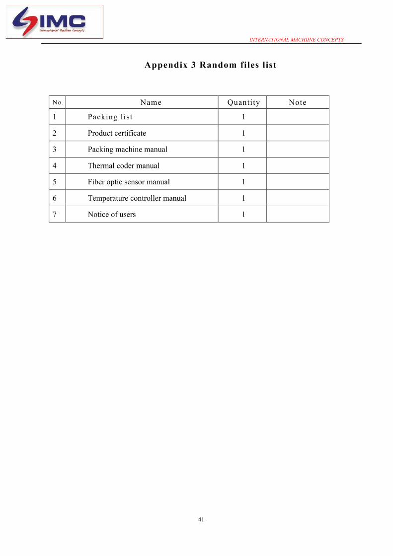
Appendix 3 Random files list
No. Name Quantity Note
1 Packing list 1
2 Product certificate 1
3 Packing machine manual 1
4 Thermal coder manual 1
5 Fiber optic sensor manual 1
6 Temperature controller manual 1
7 Notice of users 1

INTERNATIONAL MACHIINE CONCEPTS
42
Appendix 4 Spare parts and spare parts list
No. Name Model specification Quantity Remark
1 Electric rod
#20x350 AC220V 1000W 2
#20x190 AC220V 800W 2
#16x190 AC220V 500W 2
2 Electric couple K,M6 2
3 Replay 2
4 Solid state relay 2
5 O-type rubber sealing ring of hydraulic and pneumatic
#48.7X5.3G 4
6 Gasket #25.4 2
7 Discharge mouth pad 4
8 Silicon rubber plate 400x500x4
1
9 PTFE heat-resistant tape 90 wide 1volume
55 wide 2 volumes
10 Wallpaper blade 1 box
11 Hexagon wrench 1 set
12 Opening wrench 1 set
13 - type screwdriver 1
14 Cross type screwdriver 1
15 Plunger 4 sets
16 Character (English) 1 boxes
17 Color tape 5 volumes
18 Printer accessories 1 sets
19 Silicon adhesives 704 2 boxes
20 Fuse 10A 10
21 Tool box 1

INTERNATIONAL MACHIINE CONCEPTS
43
Appendix 5 Transmembrane schematic diagram

INTERNATIONAL MACHIINE CONCEPTS
44

INTERNATIONAL MACHIINE CONCEPTS
45
Appendix 6 Packing list IMCL-500 model No.
Name Quantity Remarks
1
Host (packing machine) 1、 Main body of the packing machine 2、 Mechanism of the former 3、 Operation box (touch screen) 4、 Belt conveyor 5、 Removed other parts from the host
(liquid supply tubes, clamps, gaskets, bottom feet, etc.)
1 set 1# packing box
2 Spare parts and parts Pack it by Spare Parts and Parts List.
3 Random files Pack it by Random Files List.
Supervisor for packing: Quality Inspection Department: