Embed Size (px)
Citation preview

OPERATION, MAINTENANCE, AND
MONITORING PLAN
VOLUME 3
Leachate Management Systems
Prepared for:
Bridgeton Landfill, LLC
13570 St. Charles Rock Rd.
Bridgeton, MO 63044
Prepared by:
Civil & Environmental Consultants, Inc.
4848 Park 370 Blvd., Suite F
Hazelwood, MO 63042
CEC PROJECT NO. 131-178
September 2013
Note: This Volume of the OM&M Plan is a work-in-progress and will require
future revisions as significant expansions and revisions are made to the leachate
management system over the next several months.

Operation, Maintenance, and Monitoring Plan
Volume 3 – Leachate Management Systems
Bridgeton Landfill
September 13, 2013
The material and data in this report was compiled and/or prepared under the responsible charge,
supervision, and direction of the undersigned.
Civil & Environmental Consultants, Inc.
______________________________
Michael R. Beaudoin, P.E. (primary registration Michigan)
Principal
Ivan A. Cooper, P.E. BCEE
Principal
Professional Engineer, Licensed in the State of Missouri
Operation, Maintenance and Monitoring Plan – Volume 3 Bridgeton Landfill
R-131-178 -i- September 2012
TABLE OF CONTENTS
1.0 INTRODUCTION ........................................................................................................................... 1
1.1 Background ................................................................................................................................... 1 1.2 Current Status of the Leachate Management System ................................................................... 2 1.3 Components of the Leachate Management System ...................................................................... 3
2.0 OPERATION ................................................................................................................................... 5
2.1 Liquid Collection System.............................................................................................................. 5
2.1.1 Leachate Collection Sumps ................................................................................................... 5 2.1.2 Gas Extraction Well Dewatering .......................................................................................... 5 2.1.3 Subcap Collection (South Quarry Area) ............................................................................... 5 2.1.4 Condensate Removal............................................................................................................. 5
2.2 Liquid Conveyance System .......................................................................................................... 6
2.2.1 Lateral Conveyance Piping ................................................................................................... 6 2.2.2 Pump and Lift Stations .......................................................................................................... 6 2.2.3 Perimeter Force Main ............................................................................................................ 6
2.3 Leachate Pretreatment System ...................................................................................................... 6
3.0 MAINTENANCE ............................................................................................................................ 7
3.1 Liquid Collection System.............................................................................................................. 7
3.1.1 Leachate Collection Sumps ................................................................................................... 7 3.1.2 Gas Extraction Well Dewatering .......................................................................................... 7 3.1.3 Subcap Collection ................................................................................................................. 7 3.1.4 Condensate Removal............................................................................................................. 8
3.2 Liquid Conveyance System .......................................................................................................... 8
3.2.1 Lateral Conveyance Piping ................................................................................................... 8 3.2.2 Pump Stations ....................................................................................................................... 8 3.2.3 Perimeter Force Main ............................................................................................................ 8
3.3 Leachate Pretreatment System ...................................................................................................... 8

Operation, Maintenance, and Monitoring Plan – Volume 3 Bridgeton Landfill
R-131-178 -ii- September 2013
TABLES
Table 1 Inspection and Maintenance for the Leachate Management Systems
FIGURES
Figure 1 Leachate Management System Schematic
APPENDICES
Appendix A Leachate Collection Sump Operating Procedures Appendix B Leachate Collection Sump Inspection Form Appendix C Subcap Leachate Collector Inspection Form
Appendix D Transmission Pipe Maintenance Procedures
Appendix E Pump Station Maintenance Procedures (to be provided after Fall 2013
improvements)
Appendix F Leachate Storage/Treatment Tank Maintenance Procedures
DOCUMENTS INCORPORATED BY REFERENCE
1) Leachate Tank and Transport Disposal/Leachate Management, May 30, 2013 by Civil &
Environmental Consultants
Operation and Maintenance Manual by Landmarc Environmental Systems
Interim Leachate Management Plan by Feezor Engineering
2) Bridgeton Landfill Leachate Tank and Transport Disposal/Leachate Management, July
25, 2013 by Civil & Environmental Consultants, Inc.
Updated Interim Leachate Management Plan by Feezor Engineering
3) Leachate Pre-Treatment System Plan, August 30, 2013 (Revised September 9, 2013) by
Civil & Environmental Consultants
Operation, Maintenance and Monitoring Plan – Volume 3 Bridgeton Landfill
R-131-178 -1- September 2012
1.0 INTRODUCTION
1.1 Background
This document comprises Volume 3 of a three-volume Operation, Maintenance, and Monitoring
Plan (OM&M Plan) for the Bridgeton Landfill, LLC (Bridgeton Landfill). The OM&M Plan
consists of:
Volume 1 - General Requirements and Surface Systems
Volume 2 - Gas and Subsurface Control Systems
Volume 3 – Leachate Management Systems (this volume)
Volume 1 describes the history of the landfill as well as the OM&M Plan purpose, management
structure, data collection and reporting, and procedures for Plan modifications.
Certain reactions (also called a subsurface smoldering event or SSE) are believed to be occurring
within portions of the landfill. The effects of the reactions produce untypical and stressful
conditions on the leachate management systems including:
Elevated temperatures which require special construction materials,
Thermal decomposition (pyrolysis) of waste resulting in much higher than typical levels
of BOD, COD, volatile organic compounds, and certain dissolved metals in the leachate,
Drying of waste which results in a steam/water vapor front moving out, up, and away
from the reaction which then condenses in the cooler surrounding waste mass, and gas
extraction wells, resulting in high liquid generation and obstruction of gas extraction well
perforations,
Higher-than-normal temperature adjacent to the reacting waste mass, causing conversion
of liquid into steam and the potential for forceful ejection of liquid in some locations, and
Settlement under and/or adjacent to reacting waste mass creating pinches, warps, and or
breaks in the leachate management features.
Each of these conditions results in operational and maintenance challenges. It is not known how
long the SSE will continue or how long these conditions will exist, but it is believed the elevated
temperatures and atypical liquid conditions will be present for many years. Therefore, special
operating and maintenance procedures are, and will be, necessary for the leachate management
systems until conditions allow for resumption of typical procedures.

Operation, Maintenance, and Monitoring Plan – Volume 3 Bridgeton Landfill
R-131-178 -2- September 2013
Currently, the SSE is contained to the South Quarry, and measures are being taken to prevent it
from entering the North Quarry. As a result, the leachate removal conditions are very different
in the (impacted) South Quarry and the (non-impacted) North Quarry.
1.2 Current Status of the Leachate Management System
As of this writing, the leachate management system is undergoing significant upgrades and
modifications that have been required due to the increase in volume and increase in leachate
“strength” that has occurred as a result of the SSE. Therefore, this volume of the OM&M Plan
will be significantly expanded and revised over the next several months to accommodate new
and upgraded systems.
Operation and maintenance procedures currently in use are primarily those presented in the
following document:
Leachate Tank and Transport Disposal/Leachate Management, May 30, 2013 by Civil &
Environmental Consultants, Inc.
o Operation and Maintenance Manual by Landmarc Environmental Systems
o Interim Leachate Management Plan by Feezor Engineering
Bridgeton Landfill Leachate Tank and Transport Disposal/Leachate Management, July
25, 2013 by Civil & Environmental Consultants, Inc.
o Updated Interim Leachate Management Plan by Feezor Engineering
The facility is currently under construction toward the goal of the final leachate pretreatment
procedures outlined in the following documents:
Leachate Pre-Treatment System Plan, August 30, 2013 (Revised September 9, 2013) by
Civil & Environmental Consultants
Treatment Building Construction Plans for Bridgeton Landfill, August 30, 2013 by Civil
& Environmental Consultants, Inc.
Both of the above-referenced documents are works in progress and subject to modification prior
to finalization and implementation.
In addition, upgrades and improvements are being made to the leachate conveyance systems, the
design of which is being performed by Weaver Boos.
Operation, Maintenance, and Monitoring Plan – Volume 3 Bridgeton Landfill
R-131-178 -3- September 2013
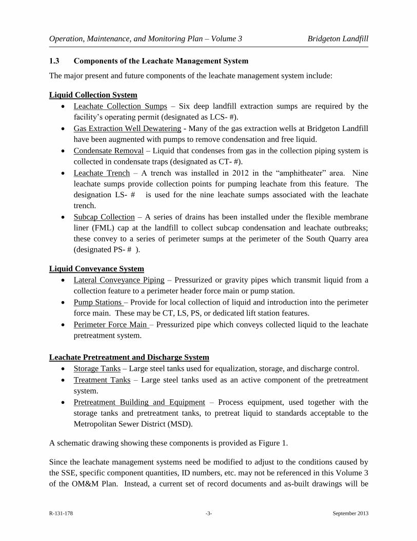
1.3 Components of the Leachate Management System
The major present and future components of the leachate management system include:
Liquid Collection System
Leachate Collection Sumps – Six deep landfill extraction sumps are required by the
facility’s operating permit (designated as LCS- #).
Gas Extraction Well Dewatering - Many of the gas extraction wells at Bridgeton Landfill
have been augmented with pumps to remove condensation and free liquid.
Condensate Removal – Liquid that condenses from gas in the collection piping system is
collected in condensate traps (designated as CT- #).
Leachate Trench – A trench was installed in 2012 in the “amphitheater” area. Nine
leachate sumps provide collection points for pumping leachate from this feature. The
designation LS- # is used for the nine leachate sumps associated with the leachate
trench.
Subcap Collection – A series of drains has been installed under the flexible membrane
liner (FML) cap at the landfill to collect subcap condensation and leachate outbreaks;
these convey to a series of perimeter sumps at the perimeter of the South Quarry area
(designated PS- # ).
Liquid Conveyance System
Lateral Conveyance Piping – Pressurized or gravity pipes which transmit liquid from a
collection feature to a perimeter header force main or pump station.
Pump Stations – Provide for local collection of liquid and introduction into the perimeter
force main. These may be CT, LS, PS, or dedicated lift station features.
Perimeter Force Main – Pressurized pipe which conveys collected liquid to the leachate
pretreatment system.
Leachate Pretreatment and Discharge System
Storage Tanks – Large steel tanks used for equalization, storage, and discharge control.
Treatment Tanks – Large steel tanks used as an active component of the pretreatment
system.
Pretreatment Building and Equipment – Process equipment, used together with the
storage tanks and pretreatment tanks, to pretreat liquid to standards acceptable to the
Metropolitan Sewer District (MSD).
A schematic drawing showing these components is provided as Figure 1.
Since the leachate management systems need be modified to adjust to the conditions caused by
the SSE, specific component quantities, ID numbers, etc. may not be referenced in this Volume 3
of the OM&M Plan. Instead, a current set of record documents and as-built drawings will be

Operation, Maintenance, and Monitoring Plan – Volume 3 Bridgeton Landfill
R-131-178 -4- September 2013
maintained in the Environmental Manager’s office at all times. In addition, this volume
references other documents that will be kept on site including: a Health and Safety Plan
(specifically designed for activities related to this OM&M Plan), equipment operating manuals,
etc.

Operation, Maintenance, and Monitoring Plan – Volume 3 Bridgeton Landfill
R-131-178 -5- September 2013
2.0 OPERATION
2.1 Liquid Collection System
2.1.1 Leachate Collection Sumps
Leachate Collection Sumps (LCS) are the primary leachate removal feature at the Bridgeton
Landfill. In accordance with Operating Permit #118912, leachate levels in the six sumps must be
maintained no more than 50 feet (North Quarry) or 30 feet (South Quarry) above the bottom of
the sump.
Presence of the thermal event has made long-term successful operation of the sumps in the South
Quarry area more challenging due to the accelerated settlement (which warps and displaces the
sump casing) and elevated temperatures (which stresses the mechanical components of the sump
and may produce a thick, tar-like substance that clogs well screens and pumps). Procedures for
operating the leachate collection sumps are provided in Appendix A and Table 1.
2.1.2 Gas Extraction Well Dewatering
Efficiency for some gas extraction wells is enhanced by adding dedicated down-hole leachate
pumps. Liquid pumped from these dual phase gas/leachate extraction wells is directed to the
leachate collection system via a network of liquid transmission lines, which are connected to the
perimeter leachate collection system. Operation and details regarding this system are provided in
Volume 2 of this OM&M Plan.
2.1.3 Subcap Collection (South Quarry Area)
The subcap drains are a series of liquid infiltration drains installed beneath the FML cap areas.
The drains convey collected liquid to the leachate collection system. These drains collect liquids
that might be expressed onto the ground surface and from condensation which may occur below
the temporary FML cap. Liquids collected by the subcap collection drains are passively
conveyed by gravity to a series of perimeter sumps installed near the perimeter or toe of slope
(designated with PS- prefix on Figure 1). Liquid collected in the LS features is introduced into
the liquid collection system with pneumatic pumps as described in Section 2.2.2.
2.1.4 Condensate Removal
For purposes of this document, condensate will be considered liquid that forms in the Gas
Collection and Control System (GCCS) lateral and header pipes due to temperature drop and
condensation of liquid out of the gas stream. Condensate drains thorough the gas conveyance
pipes by gravity and is collected near the perimeter of the landfill in condensate traps or sumps
(designated with CT- # prefix on Figure 1). From there it is pumped into the perimeter force

Operation, Maintenance, and Monitoring Plan – Volume 3 Bridgeton Landfill
R-131-178 -6- September 2013
main and comingled with leachate at the site. The condensate traps are operated as pump
stations as described in Section 2.2.2.
2.2 Liquid Conveyance System
2.2.1 Lateral Conveyance Piping
Below-grade and above-grade leachate transmission pipes are used to convey leachate from
sumps, dewatering wells, and subcap drains to a larger-diameter perimeter leachate collection
pipe. The conveyance piping are passive features which do not require specific operating
procedures. Inspection and maintenance are discussed in Section 3.2.1.
2.2.2 Pump and Lift Stations
As previously discussed, a new pump station is currently being redesigned together with a new
perimeter force main; a comprehensive set of operating procedures for the new pump station will
be provided prior to operation. In addition, any location in which a pump is placed to lift liquid
out of a vessel and into the perimeter force main is included in this category (e.g. leachate sumps
and condensate traps).
2.2.3 Perimeter Force Main
Below-grade and above-grade leachate perimeter force main are used to convey leachate from
the pump stations to the leachate pretreatment area. The force mains are passive features which
do not require specific operating procedures. Inspection and maintenance are discussed in
Section 3.2.3.
2.3 Leachate Pretreatment System
As previously discussed, leachate treatment is currently in an interim management stage until the
new systems have been implemented. At the present time, operation and maintenance of the
leachate pretreatment system is described in the following documents:
1) Leachate Tank and Transport Disposal/Leachate Management, May 30, 2013 by Civil &
Environmental Consultants
Operation and Maintenance Manual by Landmarc Environmental Systems
Interim Leachate Management Plan by Feezor Engineering
2) Bridgeton Landfill Leachate Tank and Transport Disposal/Leachate Management, July
25, 2013 by Civil & Environmental Consultants, Inc.
Updated Interim Leachate Management Plan by Feezor Engineering

Operation, Maintenance, and Monitoring Plan – Volume 3 Bridgeton Landfill
R-131-178 -7- September 2013
3.0 MAINTENANCE
The leachate collection system has been designed and constructed to meet current state-of-the-
practice operation, durability, and environmental security. However, it is a complex mechanical
and electrical system having many components subject to severe environmental and chemical
stresses in normal circumstances and which are exacerbated by the conditions caused by the
SSE. These stresses include:
Harsh weather conditions
Continuous operation
High liquid temperatures
Corrosive liquids
Aggressive compounds detrimental to most seals and gaskets
Potentially explosive vapors
High dissolved organic solids and biological anaerobes
High dissolved mineral content
Even the most robust systems operating in these conditions require consistent maintenance to
provide satisfactory operation and performance. The nature of some of the conditions noted is
unique to the SSE in the South Quarry area, and as such, Bridgeton Landfill has evolved
maintenance regimens not normally required at a typical MSW landfill.
3.1 Liquid Collection System
3.1.1 Leachate Collection Sumps
Inspections and maintenance required for the LCS sumps are provided on Table 1. A form to be
completed for the inspections is provided as Appendix B.
3.1.2 Gas Extraction Well Dewatering
Inspection and maintenance details regarding this system are provided in Volume 2 of this
OM&M Plan.
3.1.3 Subcap Collection
Inspection and maintenance procedures for the subcap drains are provided in Appendix C and
Table 1.

Operation, Maintenance, and Monitoring Plan – Volume 3 Bridgeton Landfill
R-131-178 -8- September 2013
3.1.4 Condensate Removal
Inspections and maintenance required for the condensate traps (CT- #) are provided on Table 1.
A form to be completed for the inspections is provided as Appendix E.
3.2 Liquid Conveyance System
3.2.1 Lateral Conveyance Piping
Maintenance procedures for solid single-wall and double-walled leachate transmission pipes are
provided in Appendix D.
3.2.2 Pump Stations
Perform the maintenance tasks identified in Appendix E at the frequencies presented in Table 1.
3.2.3 Perimeter Force Main
Maintenance procedures for solid single-wall and double-walled perimeter force main pipes are
provided in Appendix D.
3.3 Leachate Pretreatment System
As previously discussed, leachate treatment is currently in an interim management stage until the
new systems have been implemented. At the present time, operation and maintenance of the
leachate pretreatment system is described in the following documents which are incorporated
into this volume of the OM&M Plan by reference:
1) Leachate Tank and Transport Disposal/Leachate Management, May 30, 2013 by Civil &
Environmental Consultants
Operation and Maintenance Manual by Landmarc Environmental Systems
Interim Leachate Management Plan by Feezor Engineering
2) Bridgeton Landfill Leachate Tank and Transport Disposal/Leachate Management, July
25, 2013 by Civil & Environmental Consultants, Inc.
Updated Interim Leachate Management Plan by Feezor Engineering

TABLES
Bridgeton Landfill OM&M Plan Volume 3 September 2013
CEC Project 131-178
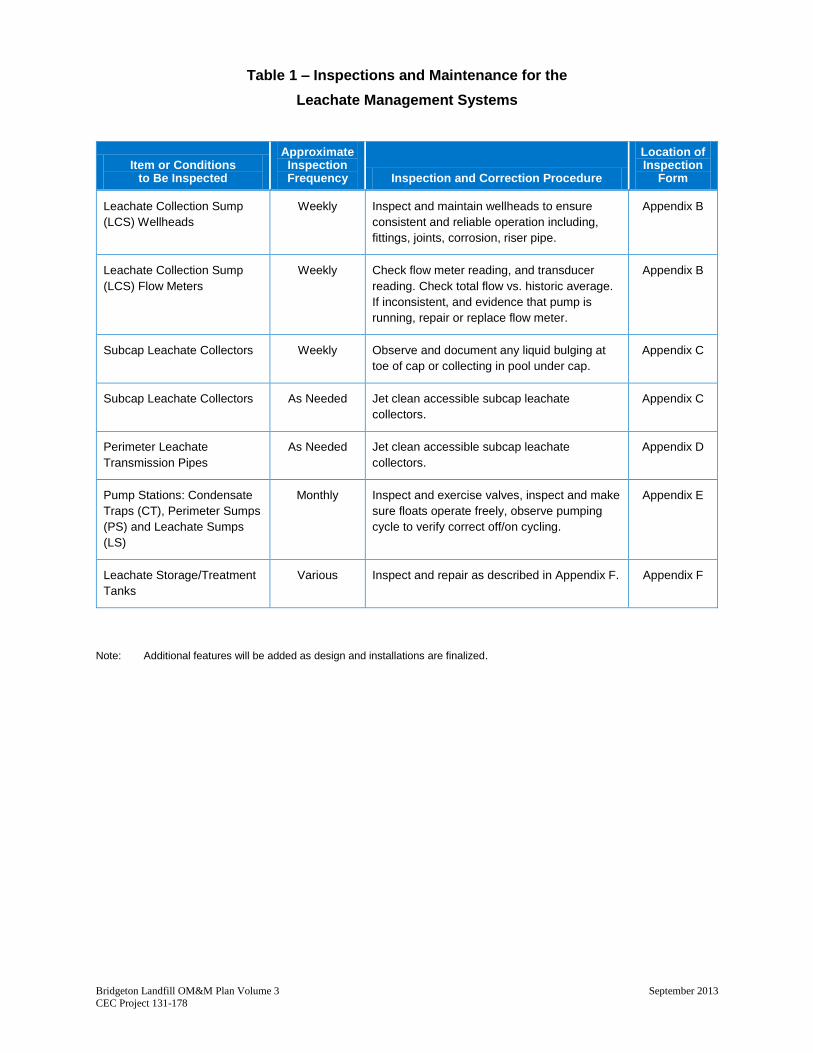
Table 1 – Inspections and Maintenance for the
Leachate Management Systems
Item or Conditions to Be Inspected
Approximate Inspection Frequency Inspection and Correction Procedure
Location of Inspection
Form
Leachate Collection Sump
(LCS) Wellheads
Weekly Inspect and maintain wellheads to ensure
consistent and reliable operation including,
fittings, joints, corrosion, riser pipe.
Appendix B
Leachate Collection Sump
(LCS) Flow Meters
Weekly Check flow meter reading, and transducer
reading. Check total flow vs. historic average.
If inconsistent, and evidence that pump is
running, repair or replace flow meter.
Appendix B
Subcap Leachate Collectors Weekly Observe and document any liquid bulging at
toe of cap or collecting in pool under cap.
Appendix C
Subcap Leachate Collectors As Needed Jet clean accessible subcap leachate
collectors.
Appendix C
Perimeter Leachate
Transmission Pipes
As Needed Jet clean accessible subcap leachate
collectors.
Appendix D
Pump Stations: Condensate
Traps (CT), Perimeter Sumps
(PS) and Leachate Sumps
(LS)
Monthly Inspect and exercise valves, inspect and make
sure floats operate freely, observe pumping
cycle to verify correct off/on cycling.
Appendix E
Leachate Storage/Treatment
Tanks
Various Inspect and repair as described in Appendix F. Appendix F
Note: Additional features will be added as design and installations are finalized.

FIGURES

DATE: DWG SCALE:
DRAWN BY: CHECKED BY: APPROVED BY:
PROJECT NO:
FIGURE NO.:
LEACHATE MANAGEMENTSYSTEMS SCHEMATIC
131-1781"=200'AUG. 2013MSP MRB IAC
1
BRIDGETON LANDFILLOPERATION, MAINTENANCE,
& MONITORING PLANVOLUME 3
4848 Park 370 Blvd., Suite F - Hazelwood, MO 63042314-656-4566 · 866-250-3679
www.cecinc.com
NORTH
LEGEND
NOTES

APPENDIX A
LEACHATE COLLECTION SUMP OPERATING PROCEDURES

APPENDIX A
Bridgeton Landfill OM&M Plan Volume 3 September 2013 CEC Project 131-178
Leachate Collection Sump Operation Procedures
Leachate Collection Sumps (LCS) are each programmed to operate using dedicated 3-phase
electrical pumps, transducers and variable frequency drives (VFDs).
Individual pumps are sized based on sump depth and historical leachate volume. Pump
manufacturer information and LCS as-built documentation will be retained in the site file
system in a binder “Leachate Collection Sumps.”
VFDs shall be programmed to pump liquid to a specified set-point (either 30’ above
quarry floor or 50’ above quarry floor as required by Operating permit No. 118912) and
hold that level by regulating pump speed and operation as the sump recharges.
Operate LCS pumps 24 hours per day, with automated temporary shutdown periods when
pumping rate exceeds liquid recharge.
Use Appendix B form for documenting operational problems or issues.

APPENDIX B
LEACHATE COLLECTION SUMP OPERATING FORM

Page 1 of 2
APPENDIX B
BRIDGETON LANDFILL
LEACHATE COLLECTION SUMP INSPECTION FORM
Date of Inspection: _______________
Name of Inspector: ________________________________________________________
Inspection Item Item Tracking Number(s)
Weekly
Fittings
Joints
Corrosion
Riser Vertically
Absence of Flow
Flow Meter Performance
Flow Meter Reading
Transducer Reading
Control Room Climate Control System
Note: See attached Leachate Collection Sump Inspection Item Tracking Form (one per
item indicated on the above form).
Inspection Items
Sump ID Date Time
LCS-1D
LCS-2C
LCS-3C
LCS-4B
LCS-5A
LCS-6B
Page 2 of 2
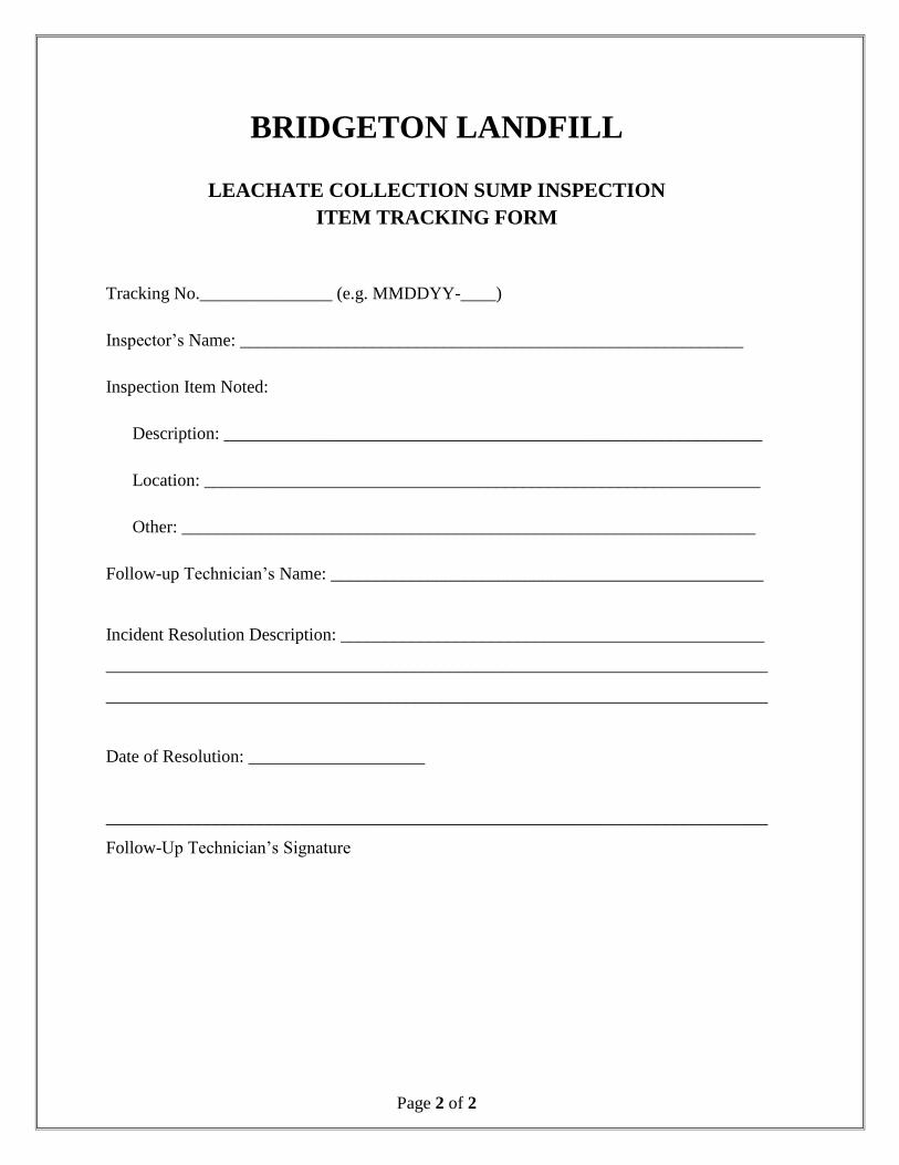
BRIDGETON LANDFILL
LEACHATE COLLECTION SUMP INSPECTION
ITEM TRACKING FORM
Tracking No._______________ (e.g. MMDDYY-____)
Inspector’s Name: _________________________________________________________
Inspection Item Noted:
Description: _____________________________________________________________
Location: _______________________________________________________________
Other: _________________________________________________________________
Follow-up Technician’s Name: _________________________________________________
Incident Resolution Description: ________________________________________________
___________________________________________________________________________
___________________________________________________________________________
Date of Resolution: ____________________
___________________________________________________________________________
Follow-Up Technician’s Signature

APPENDIX C
SUBCAP LEACHATE COLLECTOR INSPECTION FORM

Page 1 of 2
APPENDIX C
BRIDGETON LANDFILL
SUB-CAP LEACHATE COLLECTOR INSPECTION FORM
Date of Inspection: _______________
Name of Inspector: ________________________________________________________
Inspection Item Item Tracking Number(s)
Weekly
Liquid at toe of slope
Liquid pool under cap
Annually
Jet clean sub-cap collectors
Note: See attached Sub-cap Leachate Collection Inspection Item Tracking Form (one
per item indicated on the above form).

Page 2 of 2
BRIDGETON LANDFILL
SUB-CAP LEACHATE COLLECTOR TRACKING FORM
Tracking No._______________ (e.g. MMDDYY-____)
Inspector’s Name: _________________________________________________________
Inspection Item Noted:
Description: _____________________________________________________________
Location: _______________________________________________________________
Other: _________________________________________________________________
Follow-up Technician’s Name: _________________________________________________
Incident Resolution Description: ________________________________________________
___________________________________________________________________________
___________________________________________________________________________
Date of Resolution: ____________________
___________________________________________________________________________
Follow-Up Technician’s Signature

APPENDIX D
TRANSMISSION PIPE MAINTENANCE PROCEDURES
APPENDIX D
Bridgeton Landfill OM&M Plan Volume 3 September 2013 CEC Project 131-178
Leachate Transmission Pipe Maintenance Procedures
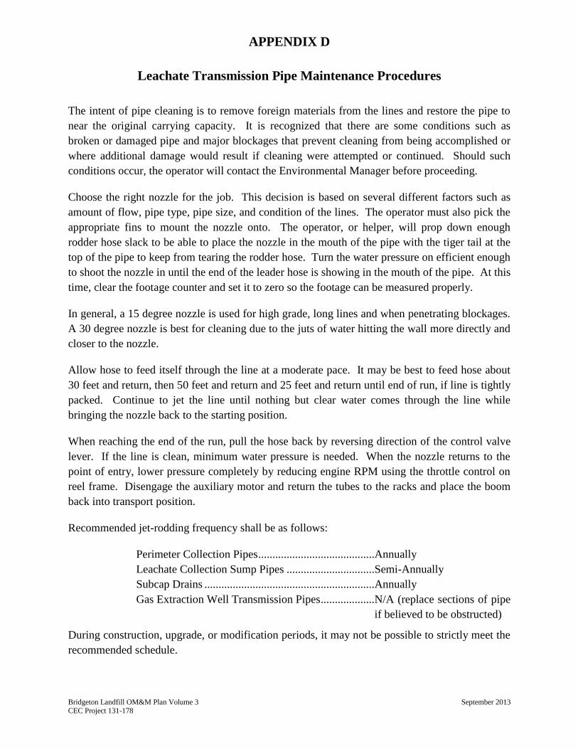
The intent of pipe cleaning is to remove foreign materials from the lines and restore the pipe to
near the original carrying capacity. It is recognized that there are some conditions such as
broken or damaged pipe and major blockages that prevent cleaning from being accomplished or
where additional damage would result if cleaning were attempted or continued. Should such
conditions occur, the operator will contact the Environmental Manager before proceeding.
Choose the right nozzle for the job. This decision is based on several different factors such as
amount of flow, pipe type, pipe size, and condition of the lines. The operator must also pick the
appropriate fins to mount the nozzle onto. The operator, or helper, will prop down enough
rodder hose slack to be able to place the nozzle in the mouth of the pipe with the tiger tail at the
top of the pipe to keep from tearing the rodder hose. Turn the water pressure on efficient enough
to shoot the nozzle in until the end of the leader hose is showing in the mouth of the pipe. At this
time, clear the footage counter and set it to zero so the footage can be measured properly.
In general, a 15 degree nozzle is used for high grade, long lines and when penetrating blockages.
A 30 degree nozzle is best for cleaning due to the juts of water hitting the wall more directly and
closer to the nozzle.
Allow hose to feed itself through the line at a moderate pace. It may be best to feed hose about
30 feet and return, then 50 feet and return and 25 feet and return until end of run, if line is tightly
packed. Continue to jet the line until nothing but clear water comes through the line while
bringing the nozzle back to the starting position.
When reaching the end of the run, pull the hose back by reversing direction of the control valve
lever. If the line is clean, minimum water pressure is needed. When the nozzle returns to the
point of entry, lower pressure completely by reducing engine RPM using the throttle control on
reel frame. Disengage the auxiliary motor and return the tubes to the racks and place the boom
back into transport position.
Recommended jet-rodding frequency shall be as follows:
Perimeter Collection Pipes .........................................Annually
Leachate Collection Sump Pipes ...............................Semi-Annually
Subcap Drains ............................................................Annually
Gas Extraction Well Transmission Pipes ...................N/A (replace sections of pipe
if believed to be obstructed)
During construction, upgrade, or modification periods, it may not be possible to strictly meet the
recommended schedule.
APPENDIX D
Bridgeton Landfill OM&M Plan Volume 3 September 2013 CEC Project 131-178
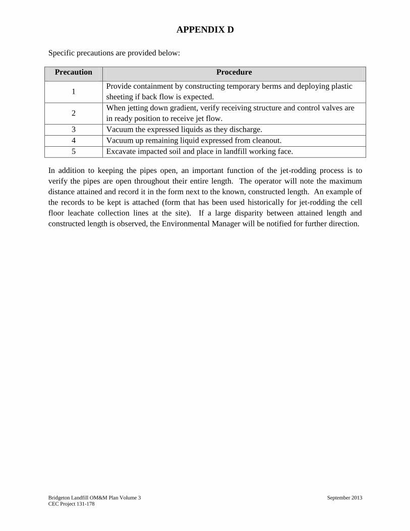
Specific precautions are provided below:
Precaution Procedure
1 Provide containment by constructing temporary berms and deploying plastic
sheeting if back flow is expected.
2 When jetting down gradient, verify receiving structure and control valves are
in ready position to receive jet flow.
3 Vacuum the expressed liquids as they discharge.
4 Vacuum up remaining liquid expressed from cleanout.
5 Excavate impacted soil and place in landfill working face.
In addition to keeping the pipes open, an important function of the jet-rodding process is to
verify the pipes are open throughout their entire length. The operator will note the maximum
distance attained and record it in the form next to the known, constructed length. An example of
the records to be kept is attached (form that has been used historically for jet-rodding the cell
floor leachate collection lines at the site). If a large disparity between attained length and
constructed length is observed, the Environmental Manager will be notified for further direction.

APPENDIX E
PUMP STATION MAINTENANCE PROCEDURES
(To Be Provided After Fall 2013 Improvements)

APPENDIX F
LEACHATE STORAGE/TREATMENT TANK MAINTENANCE
PROCEDURES
(Procedures To Be Modified And Supplemented As Additional Tanks Are
Constructed And Utilized)
APPENDIX F
Bridgeton Landfill
96,000 Gallon Leachate Tank System
Standard Operating Procedure
July 2012 Rev. September 2013
Bridgeton, Missouri 13570 St. Charles Rock Road
Bridgeton, Missouri 63044 Telephone: (314) 744-8190 Facsimile: (314) 739-2588

Bridgeton Landfill Leachate Tank System SOP Bridgeton Landfill, Bridgeton, Missouri Page i
TABLE OF CONTENTS
1.0 INTRODUCTION ........................................................................................................................................... 1
1.1 Tank Background and Goal .................................................................................................................... 1 1.2 List of Leachate Tank Operations Personnel ...................................................................................... 1
2.0 LEACHATE TANK SYSTEM OPERATION AND MAINTENANCE ................................................... 3
2.1 Tank Level Control Valve ......................................................................................................................... 3 2.2 Leachate Atomizer .................................................................................................................................... 3 2.3 Leachate Circulator ................................................................................................................................... 4 2.4 Gas Extraction Vacuum Line .................................................................................................................. 4 2.5 Carbon Vessel Filtration System ............................................................................................................ 5
3.0 ADDITIONAL MEASURES ......................................................................................................................... 7
3.1 Bridgeton Landfill Discharge Junction Vault Monitoring .................................................................... 7
ATTACHMENTS
Attachment A – Storage Tank Inspection Form Attachment B – Tank Diagram

Bridgeton Landfill Leachate Tank System SOP Bridgeton Landfill, Bridgeton, Missouri Page 1
1.0 INTRODUCTION
This document is the site Standard Operating Procedure (SOP) for operation and maintenance of the leachate tank system at the Bridgeton Landfill, 13570 St. Charles Rock Road, Bridgeton, Missouri 63044. This SOP has been developed by the Bridgeton Landfill for use by onsite personnel involved with the leachate tank system operation and preventative maintenance. The purpose of this document is to establish a set timeframe for inspection, operation, maintenance, repair, and regeneration of each of the components of the facilities leachate storage, recirculation, and extraction tank to sustain permissible discharge effluent of the facility.
1.1 Tank Background and Goal Leachate is permitted to be discharged to the Metropolitan St. Louis Sewer District (MSD) under Wastewater Discharge Permit No. 0511559802-2. To assist the facility in ensuring that effluent leachate constituent concentrations are below permitted limitations, and that excessive levels of methane and hydrogen sulfide are not released into the MSD sanitary sewer system the facility has implemented a number of engineering controls. The Bridgeton Landfill utilizes an 96,000-gallon capacity Aquastore, glass-lined liquid collection tank to contain, recirculate, atomize, and subsequently extract toxic gases entrained in the leachate produced within the facility prior to discharging. The tank has a series of valves that can be actuated to regulate various activities within. Dependent on valve position the tank liquid level and discharge rate can be controlled, the leachate can be stirred to free up any tank deposits from settling, or it can be run through the atomizer. The leachate tank is also fitted with a 2” high-density polyethylene vacuum line. This line, operating courtesy of vacuum provided by the landfill’s gas control and collection system blower is designed to remove gases such as methane and hydrogen sulfide commonly found in leachate, as well as vapor-phase organic constituents. As a redundancy the Bridgton Landfill leachate tank system employs a dual carbon-vessel filtration system to supplement any temporary loss of vacuum to the tank from the main extraction line. In the case of a gas collection and control system malfunction this system is able to perform the duties of gas removal from the tank until the issue can be corrected. Each system, as explained in this SOP has a monitoring schedule and contingency plan to insure proper and sustained operation.
1.2 List of Leachate Tank Operations Personnel The following table represents the Bridgeton Landfill Personnel responsible for leachate tank system operation. The table details each individual’s specific responsibilities regarding leachate tank operation and individual contact information:

Bridgeton Landfill Leachate Tank System SOP Bridgeton Landfill, Bridgeton, Missouri Page 2
Table 1-1 Leachate Tank System Operational Personnel
Title Personnel Phone numbers
Work Mobile
Environmental Manager Brian Power (314) 744-8165 (618) 410-0157
Leachate Collection System
Specialist
Bryan Sehie (314) 744-8190 (314) 443-0179
Gas Control and Collection
System Specialist
Mike Lambrich (314) 744-8175 (314) 683-3921
Bridgeton Landfill Leachate Tank System SOP Bridgeton Landfill, Bridgeton, Missouri Page 3
2.0 LEACHATE TANK SYSTEM OPERATION AND MAINTENANCE
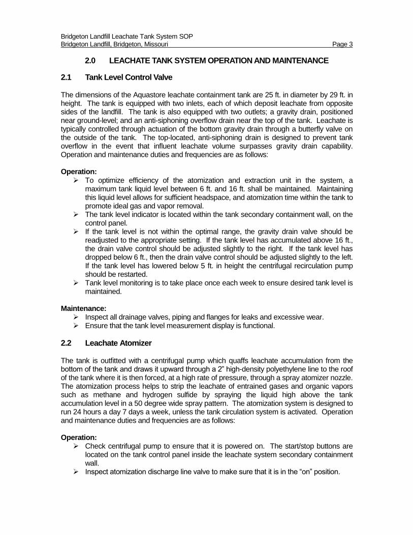
2.1 Tank Level Control Valve The dimensions of the Aquastore leachate containment tank are 25 ft. in diameter by 29 ft. in height. The tank is equipped with two inlets, each of which deposit leachate from opposite sides of the landfill. The tank is also equipped with two outlets; a gravity drain, positioned near ground-level; and an anti-siphoning overflow drain near the top of the tank. Leachate is typically controlled through actuation of the bottom gravity drain through a butterfly valve on the outside of the tank. The top-located, anti-siphoning drain is designed to prevent tank overflow in the event that influent leachate volume surpasses gravity drain capability. Operation and maintenance duties and frequencies are as follows: Operation:
To optimize efficiency of the atomization and extraction unit in the system, a maximum tank liquid level between 6 ft. and 16 ft. shall be maintained. Maintaining this liquid level allows for sufficient headspace, and atomization time within the tank to promote ideal gas and vapor removal.
The tank level indicator is located within the tank secondary containment wall, on the control panel.
If the tank level is not within the optimal range, the gravity drain valve should be readjusted to the appropriate setting. If the tank level has accumulated above 16 ft., the drain valve control should be adjusted slightly to the right. If the tank level has dropped below 6 ft., then the drain valve control should be adjusted slightly to the left. If the tank level has lowered below 5 ft. in height the centrifugal recirculation pump should be restarted.
Tank level monitoring is to take place once each week to ensure desired tank level is maintained.
Maintenance:
Inspect all drainage valves, piping and flanges for leaks and excessive wear. Ensure that the tank level measurement display is functional.
2.2 Leachate Atomizer The tank is outfitted with a centrifugal pump which quaffs leachate accumulation from the bottom of the tank and draws it upward through a 2” high-density polyethylene line to the roof of the tank where it is then forced, at a high rate of pressure, through a spray atomizer nozzle. The atomization process helps to strip the leachate of entrained gases and organic vapors such as methane and hydrogen sulfide by spraying the liquid high above the tank accumulation level in a 50 degree wide spray pattern. The atomization system is designed to run 24 hours a day 7 days a week, unless the tank circulation system is activated. Operation and maintenance duties and frequencies are as follows: Operation:
Check centrifugal pump to ensure that it is powered on. The start/stop buttons are located on the tank control panel inside the leachate system secondary containment wall.
Inspect atomization discharge line valve to make sure that it is in the “on” position.

Bridgeton Landfill Leachate Tank System SOP Bridgeton Landfill, Bridgeton, Missouri Page 4
Operational check of the leachate atomizer is to be performed once per week. Maintenance:
Inspect centrifugal pump for leaks, damage, and excessive wear. Inspect piping for leaks, and excessive wear.
2.3 Leachate Circulator The leachate circulator serves the purpose of stirring the tank to break up any deposited sediment or build-up that has settled at the bottom of the tank and allow it to drain through the lower gravity-drain outlet. The leachate circulator is typically not in operation due to the operation of the atomizer. Being that the circulation system uses the same centrifugal pump to operate as the atomizer the two systems cannot run in tandem. To stir the tank the atomizer valve must be turned to the “off” position, and the circulator value must be moved to the “on” position. This will direct liquid to the circulator. Both valves must not remain closed for an extended period of time as this will cause a “dead-pan” scenario which may cause premature damage to the pump. The operation and maintenance duties and frequencies are as follows: Operation:
When operating the circulator, first completely open the circulation valve located at the inlet of the circulation piping near the tank centrifugal pump.
Once the circulation valve is open completely close the atomizer valve. Reverse the process when finished. Check centrifugal pump to ensure that it is powered on. The start/stop buttons are
located on the tank control panel inside the leachate system secondary containment wall.
Do not operate the circulator for more than 24 hours so that the atomizer may be returned to service.
This system should only be operated on an as-needed basis. Maintenance:
Inspect centrifugal pump for leaks, damage, and excessive wear. Inspect piping for leaks, and excessive wear.
2.4 Gas Extraction Vacuum Line
Gases present from the atomization of leachate are subsequently extracted through a 2” high-density polyethylene vacuum line located at the roof of the tank. The line is directed to the landfill’s gas collection and control system network, where the captured gases are ultimately routed to the landfill flare and destroyed. The flare blower provides between 2” and 11” of vacuum at the tank for such gas removal. Similar to the gas collection system, the leachate system lines will develop condensate. As such, the leachate gas extraction system contains an underground sump which collects any accumulation of condensate in the line and pumps it back into the leachate collection system. This sump unit helps to return lost liquids to the leachate system and maintains a free flow of vacuum in the line by preventing it from “watering-in.” The operation and maintenance frequency of the gas extraction vacuum line is as follows:

Bridgeton Landfill Leachate Tank System SOP Bridgeton Landfill, Bridgeton, Missouri Page 5
Operation: The gas extraction vacuum line is always in operation so long as the landfill gas
collection and control system is also operational. A vacuum reading should be taken once each week to ensure that the system is
flowing freely. The vacuum monitoring port is located on the vacuum line at eye-level just outside of the east section of the tank secondary containment wall.
The pump in the condensate sump should be checked for operation once per week to ensure that any liquid accumulation is being removed from the system.
In the event of a gas collection and control system malfunction, the carbon filtration system should be turned on.
If necessary the vacuum to the tank can be shut off via the vacuum control valve located next to the vacuum monitoring port.
Maintenance:
Inspect all vacuum lines and fittings shall be inspected for leaks and signs of damage or excessive wear.
2.5 Carbon Vessel Filtration System
As a redundancy to the gas extraction vacuum system, the Bridgeton Landfill has also implemented a carbon vessel filtration system. This system can apply vacuum to the tank and remove gases and vapor by drawing them out through a 6” PVC line in the tank’s roof and directing them through a series of two granular activated-carbon vessels. The vessels are arranged in a lead-lag scenario were the primary (lead) vessel is designed to remove 100% of all incoming toxic gasses. Monitoring ports are installed prior to the influent of the lead vessel to collect data on gas composition as it enters the carbon media. A second sampling port is installed at the effluent of the lead vessel to monitor for any break-through. Airflow from the lead vessel effluent is subsequently directed to the second (lag) vessel as a redundancy to ensure that no possible break-through of gases to the atmosphere occurs. The effluent of the lag vessel is also monitored. The carbon filtration system has a vacuum pump that is independent of the gas collection and control system so that it can be operated in the event the latter system experiences a malfunction. This offers the ability to have uninterrupted gas and vapor removal at the leachate tank. When the carbon filtration system is in operation the operation and maintenance frequency is as follows: Operation:
In the event of a gas collection and control system malfunction the carbon filtration system shall be powered on. This can be done by positioning the carbon filtration system control lever to “on.” The control lever is located on the panel, to the right of the main leachate tank control panel, inside the secondary containment area.
During operation the three monitoring ports in the system should be read on a daily basis to ensure that hydrogen sulfide break-through at the lead vessel has not occurred. Monitoring for hydrogen sulfide will be performed using a 4-gas meter. In the event that hydrogen sulfide concentration at the effluent of the lead vessel reaches 5 ppm the carbon in the lead vessel shall be replaced.
Replacement virgin granular activated-carbon is stored onsite. Once a 5 ppm hydrogen sulfide break-through is detected, spent carbon will be removed from the lead vessel using a drum-vacuum. The carbon will be containerized in 55-gallon

Bridgeton Landfill Leachate Tank System SOP Bridgeton Landfill, Bridgeton, Missouri Page 6
drums and marked for proper disposal. Virgin carbon will be placed in the vessel and operation can be restored.
During operation of the system a daily condensate accumulation check must be performed to insure that there has not been any accumulation in the demister box. Due to the installation of a condensate knock-out pot this scenario is unlikely under daily monitoring.
The effluent to the atmosphere will be monitoring using a 4-gas meter as well to ensure overall system performance. The lag vessel will receive a carbon replacement when effluent concentration reaches a level of 5 ppm hydrogen sulfide. Replacement virgin carbon for the lag vessel is also stored onsite.
Maintenance:
Inspect all PVC, lines, piping, and valves in the carbon system network for leaks, damage, or excessive wear monthly.
Inspect demister box to ensure lid is in place, seated, and free of damage monthly. Drain any condensate from the knock-pot as needed. Make sure that carbon filtration system vacuum pump is operational on a monthly
schedule.

Bridgeton Landfill Leachate Tank System SOP Bridgeton Landfill, Bridgeton, Missouri Page 7
3.0 ADDITIONAL MEASURES
3.1 Bridgeton Landfill Discharge Junction Vault Monitoring
The Bridgeton Landfill has also installed an additional multi-gas monitoring port within the leachate discharge junction vault situated to the north of the leachate tank area. This vault is the last monitoring location of the leachate discharging from the landfill prior to entering the MSD pump station. The addition of this sampling port will allow the landfill to measure levels of methane and hydrogen sulfide in the leachate piping immediately prior to discharge. This sampling port will be monitored monthly to ensure that effluent leachate gas levels will not be excessive in the sanitary sewer system.

ATTACHMENT A
STORAGE TANK INSPECTION FORM
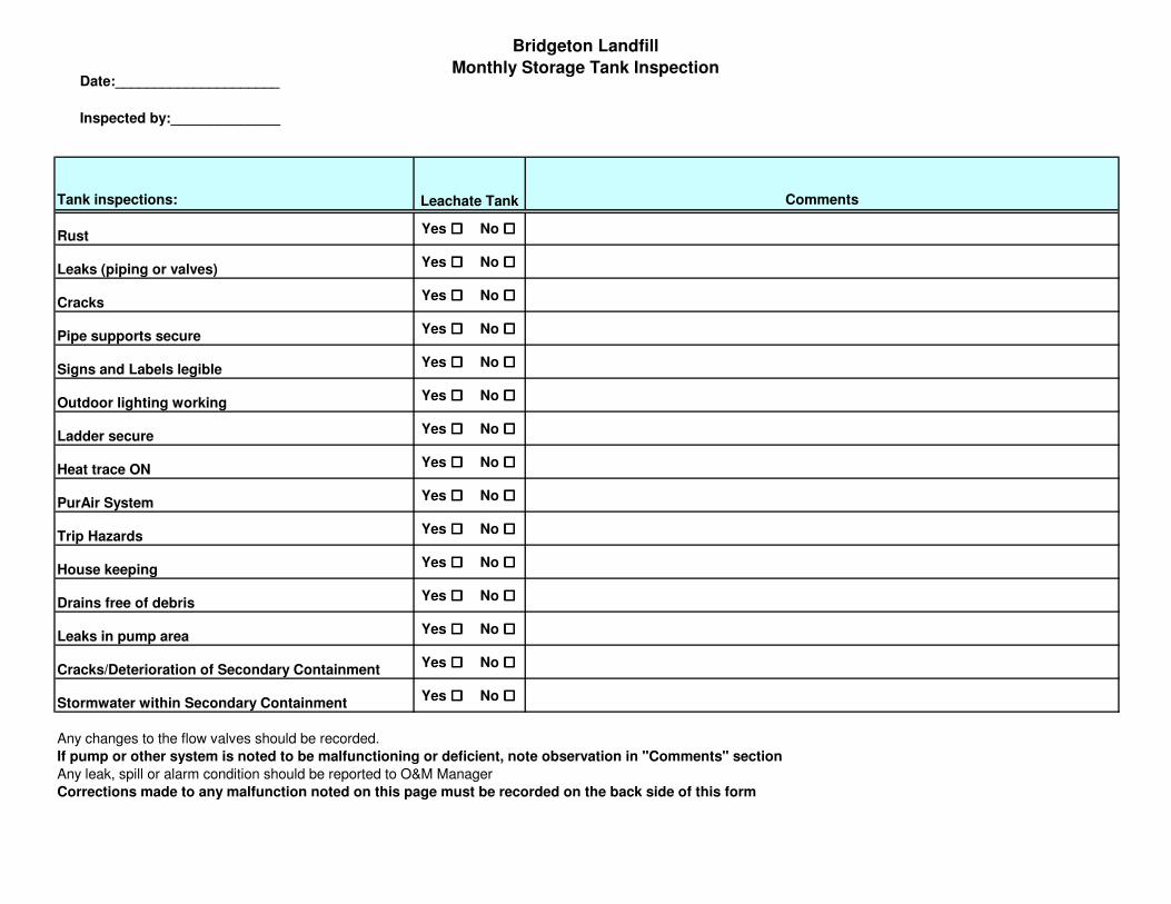
Date:_____________________
Inspected by:______________
Bridgeton Landfill
Monthly Storage Tank Inspection
Tank inspections: Comments
RustYes ���� No ����
Leaks (piping or valves)Yes ���� No ����
CracksYes ���� No ����
Pipe supports secureYes ���� No ����
Signs and Labels legibleYes ���� No ����
Outdoor lighting workingYes ���� No ����
Ladder secureYes ���� No ����
Heat trace ONYes ���� No ����
PurAir SystemYes ���� No ����
Trip HazardsYes ���� No ����
House keepingYes ���� No ����
Drains free of debrisYes ���� No ����
Leaks in pump areaYes ���� No ����
Cracks/Deterioration of Secondary ContainmentYes ���� No ����
Stormwater within Secondary ContainmentYes ���� No ����
Any changes to the flow valves should be recorded.
If pump or other system is noted to be malfunctioning or deficient, note observation in "Comments" section
Any leak, spill or alarm condition should be reported to O&M Manager
Corrections made to any malfunction noted on this page must be recorded on the back side of this form
Leachate Tank

ATTACHMENT B
TANK DIAGRAM


![Bridgeton Pioneer (Bridgeton, N.J.). 1884-09-11 [p ]. · 2018. 10. 30. · 'f lic pioneer. Bridgeton, N. J., September 11,1884. Advertisements and communications to in- sure insertion,should](https://img.dokumen.tips/doc/110x75/60b4e49fb6ffda23e0081d00/bridgeton-pioneer-bridgeton-nj-1884-09-11-p-2018-10-30-f-lic-pioneer.jpg)