Embed Size (px)
Citation preview

Vanguard 040-08OP-001B Equipment, Dec-08 Inc.
Operation and Maintenance Manual
V 561N LGP Pipelayer attachment for D5M LGP, D5N LGP S/N 040050010021 – UP (Sideboom)
TO BE USED WITH CATERPILLAR D5M OR D5N TRACTOR OPERATION AND MAINTENANCE MANUALS

VANGUARD EQUIPMENT, INC. 15627 EAST PINE ST TULSA, OKLAHOMA
74116, USA �: 918.437.1796 �: 918.437.1794

040-08OP-001B S/N 040050010021 - UP
i
Table of Contents FOREWORD ........................................................................................................................................................................... 1�
LITERATURE INFORMATION .................................................................................................................................................... 1�MACHINE DESCRIPTION ......................................................................................................................................................... 1�SAFETY ................................................................................................................................................................................... 1�OPERATION ............................................................................................................................................................................ 1�MAINTENANCE ....................................................................................................................................................................... 1�MAINTENANCE INTERVALS .................................................................................................................................................... 1�
SAFETY SECTION ................................................................................................................................................................ 2�SAFETY MESSAGES – V 561N PIPELAYER KIT ....................................................................................................................... 2�
Do Not Operate (1) ............................................................................................................................................................ 4�Electrical Power Lines (2) ................................................................................................................................................. 4�Hydraulic Accumulator (3, 4) ............................................................................................................................................ 5�Free Fall Active (5) ........................................................................................................................................................... 5�Boom Stop (6) .................................................................................................................................................................... 6�Tipover Warning (7) .......................................................................................................................................................... 6�Counterweight (8) .............................................................................................................................................................. 7�Counterweight (9) .............................................................................................................................................................. 7�
BEFORE OPERATION ............................................................................................................................................................... 7�VISIBILITY INFORMATION ....................................................................................................................................................... 8�OPERATION ............................................................................................................................................................................ 8�
Machine Operating Temperature Range ........................................................................................................................... 8�Machine Operation ............................................................................................................................................................ 8�Lifting Capacities .............................................................................................................................................................. 9�Limitations on Lifting Loads That Exceed the Working Range ......................................................................................... 9�Electrical Power Lines .................................................................................................................................................... 10�Parking ............................................................................................................................................................................ 10�Slope Operation ............................................................................................................................................................... 10�Guards ............................................................................................................................................................................. 11�
PRODUCT INFORMATION SECTION ............................................................................................................................ 12�GENERAL INFORMATION ...................................................................................................................................................... 12�
Specifications ................................................................................................................................................................... 12�Intended Use .................................................................................................................................................................... 12�Restrictions to Application and Configuration ................................................................................................................ 12�
LIFTING CAPACITIES ............................................................................................................................................................ 13�
OPERATION SECTION ...................................................................................................................................................... 15�BEFORE OPERATION ............................................................................................................................................................. 15�
Mounting and Dismounting ............................................................................................................................................. 15�Daily Inspection ............................................................................................................................................................... 15�Daily Checks .................................................................................................................................................................... 16�
MACHINE OPERATION .......................................................................................................................................................... 17�Speed/Lockout Control Lever (1) ..................................................................................................................................... 17�Speed/Lockout Control Lock (2) ...................................................................................................................................... 18�Hook Control (3) ............................................................................................................................................................. 18�Accumulator - Relieving Charge ..................................................................................................................................... 18�Boom Control (4) ............................................................................................................................................................. 19�Counterweight Control (5) .............................................................................................................................................. 19�Counterweight Control Lock (6) ...................................................................................................................................... 19�ENGINE SPEED SWITCH RELOCATED (7) ................................................................................................................. 19�HORN LOCATION MOVED (8) ...................................................................................................................................... 19�Counterweight Lock Lever ............................................................................................................................................... 20�
TRANSPORTATION INFORMATION ............................................................................................................................. 20�REMOVAL OF THE BOOM ...................................................................................................................................................... 20�
MAINTENANCE AND LUBRICATION SECTION ......................................................................................................... 22�LUBRICANT VISCOSITIES ...................................................................................................................................................... 22�GENERAL .............................................................................................................................................................................. 22�

040-08OP-001B S/N 040050010021 - UP
ii
SELECTING THE VISCOSITY .................................................................................................................................................. 22�Lubricant Viscosities for Ambient Temperatures............................................................................................................. 23�
CAPACITIES (REFILL) ........................................................................................................................................................... 23�S-O-S INFORMATION ............................................................................................................................................................ 23�MAINTENANCE INTERVAL SCHEDULE (MIS) ........................................................................................................................ 23�WHEN REQUIRED ................................................................................................................................................................. 24�
Every 10 Service Hours or Daily ..................................................................................................................................... 24�Every 50 Service Hours or Weekly .................................................................................................................................. 24�Every 500 Service Hours ................................................................................................................................................. 24�Every 500 Service Hours or 3 Months ............................................................................................................................. 24�Every 2000 Service Hours or 1 Year ............................................................................................................................... 24�
ACCUMULATOR .................................................................................................................................................................... 24�BOOM CUT-OUT VALVE ADJUSTMENT................................................................................................................................. 25�BOOM LINE – INSTALL ......................................................................................................................................................... 26�BOOM PIVOT PINS - LUBRICATE ........................................................................................................................................... 27�COUNTERWEIGHT CYLINDER BEARINGS - LUBRICATE ......................................................................................................... 28�COUNTERWEIGHT HINGE PINS - LUBRICATE ........................................................................................................................ 28�FAIRLEAD SHEAVE – LUBRICATE ......................................................................................................................................... 29�HOOK LOAD LINE – INSTALL ................................................................................................................................................ 30�HOOK AND WIRE CABLE – INSPECT ..................................................................................................................................... 31�
Inspect the Hook .............................................................................................................................................................. 31�Inspect Wire Cable .......................................................................................................................................................... 32�
HYDRAULIC SYSTEM OIL - CHANGE ..................................................................................................................................... 33�LUBRICANTS ......................................................................................................................................................................... 33�
Caterpillar Hydraulic Oils .............................................................................................................................................. 33�Commercial Oils .............................................................................................................................................................. 33�
CHANGE THE HYDRAULIC OIL .............................................................................................................................................. 34�HYDRAULIC SYSTEM OIL FILTER - REPLACE ........................................................................................................................ 35�HYDRAULIC SYSTEM OIL LEVEL – CHECK ........................................................................................................................... 36�HYDRAULIC SYSTEM OIL SAMPLING .................................................................................................................................... 36�SHEAVE BLOCK BEARING – LUBRICATE ............................................................................................................................... 36�

040-08OP-001B S/N 040050010021 - UP
1
Foreword Literature Information
This manual should be stored in the operator's compartment in the literature holder or seat back literature storage area. This manual contains safety information, operation instructions, transportation information, lubrication information and maintenance information. Some photographs or illustrations in this publication show details or attachments that can be different from your machine. Guards and covers might have been removed for illustrative purposes. Continuing improvement and advancement of product design might have caused changes to your machine which are not included in this publication. Read, study and keep this manual with the machine. Whenever a question arises regarding your machine, or this publication, please consult Vanguard Equipment for the latest available information.
Machine Description The sideboom equipment is attached to a Caterpillar D5M LGP or D5N LGP tractor. The primary use of this machine is for petroleum-product pipeline-construction in the 20- to 30-inch (510 to 765 mm) pipeline range. The operator should read, understand, and follow both the tractor and the pipelayer operating and maintenance instructions. The operator must comply with all pipelayer procedures, regulations, and safety precautions. This equipment is to be operated by qualified personnel only. The daily service/inspection procedure should be performed before start-up. Operate all pipelayer controls with no load, until familiar with machine operation. Note: Refer to the Caterpillar operation manual for detailed information on the specific operation of the tractor unit.
Safety The safety section lists basic safety precautions. In addition, this section identifies the text and locations of warning signs and labels used on the machine. Read and understand the basic precautions listed in the safety section before operating or performing lubrication, maintenance and repair on this machine.
Operation The operation section is a reference for the new operator and a refresher for the experienced operator. This section includes a discussion of gauges, switches, machine controls, attachment controls, transportation and towing information. Photographs and illustrations guide the operator through correct procedures of checking, starting, operating and stopping the machine. Operating techniques outlined in this publication are basic. Skill and techniques develop as the operator gains knowledge of the machine and its capabilities.
Maintenance The maintenance section is a guide to equipment care. The Maintenance Interval Schedule (MIS) lists the items to be maintained at a specific service interval. Items without specific intervals are listed under the "When Required" service interval. The Maintenance Interval Schedule lists the page number for the step-by-step instructions required to accomplish the scheduled maintenance. Use the Maintenance Interval Schedule as an index or "one safe source" for all maintenance procedures.
Maintenance Intervals Use the service hour meter to determine servicing intervals. Calendar intervals shown (daily, weekly, monthly, etc.) can be used instead of service hour meter intervals if they provide more convenient servicing schedules and approximate the indicated service hour meter reading Recommended service should always be performed at the interval that occurs first. Under extremely severe, dusty or wet operating conditions, more frequent lubrication than is specified in the maintenance intervals chart might be necessary. Perform service on items at multiples of the original requirement. For example, at every 500 service hours or 3 months, also service those items listed under every 250 service hours or monthly and every 10 service hours or daily.

040-08OP-001B S/N 040050010021 - UP
2
Safety Section Certain conditions and precautions are peculiar to pipelaying operations. The following represents the minimum considerations for safe operations.
Safety Messages – V 561N Pipelayer Kit
Figure 1: Safety Messages V 561N

040-08OP-001B S/N 040050010021 - UP
3
Figure 2: Safety Messages V 561N Pipelayer There are several specific safety messages on this machine. The exact location of the hazards and the description of the hazards are reviewed in this section. Please become familiarized with all safety messages. Make sure that all of the safety messages are legible. Clean the safety messages or replace the safety messages if you cannot read the words. Replace the illustrations if the illustrations are not visible. When you clean the safety messages, use a cloth, water, and soap. Do not use solvent, gasoline, or other harsh chemicals to clean the safety messages. Solvents, gasoline, or harsh chemicals could loosen the adhesive that secures the safety messages. Loose adhesive will allow the safety message to fall. Do not use pressure washers to clean the warning signs. Replace any safety message that is damaged or missing. If a safety message is attached to a part of the machine that is replaced, install a safety message on the replacement part.
8
67
4
9
030-09-005
THIS SYSTEM IS EQUIPPED WITH AN ACCUMULATOR.

040-08OP-001B S/N 040050010021 - UP
4
Do Not Operate (1)
Do not operate or work on this machine unless you have read and understand the instructions and warnings in the Operation and Maintenance Manuals. Failure to follow the instructions or heed the warnings could result in injury or death. Contact your dealer for replacement manuals. Proper care is your responsibility. Safety message (1) is located outside of the left armrest.
Figure 3: Do not operate (1)
Electrical Power Lines (2)
Electrocution Hazard! Keep the machine and attachments a safe distance from electrical power. Stay clear 3 M (10 ft) plus twice the line insulator length. Read and understand the instructions and warnings in the Operation and Maintenance Manual. Failure to follow the instructions and warnings will cause serious injury or death. Safety message (2) is located on the right side of the console and on the left center of the radiator guard.
Figure 4: Electrical power lines (2)

040-08OP-001B S/N 040050010021 - UP
5
Hydraulic Accumulator (3, 4)
This system contains high pressure gas. Failure to follow the instructions and warnings could cause an explosion, resulting in possible injury or death. Do not expose to fire. Do not weld. Do not drill. Do not remove any hydraulic system lines, taps or parts until pressure has been relieved. Relieve pressure before discharging. See Operation and Maintenance Manual "Accumulator - Relieving Charge". See Operation and Maintenance Manual "Accumulator" for charging and discharging. See your Dealer for tools and detailed information. Safety message (3) is attached to the hydraulic accumulator's access cover. The hydraulic accumulator is located behind the access cover to the right side of the operator seat.
Figure 5: Hydraulic accumulator (3) Safety message (4) is located on the right side of the console.
Figure 6: System equipped with an accumulator (4)
Free Fall Active (5) Safety message (5) is located on the right side of the control box.
Figure 7: Free fall active warning (5)
030-09-005
THIS SYSTEM IS EQUIPPED WITH AN ACCUMULATOR.

040-08OP-001B S/N 040050010021 - UP
6
Boom Stop (6) Safety message (6) is located on Left Hand tower’s cut-out valve access panel.
Figure 8: Free fall active warning (6)
Tipover Warning (7)
The machine may tip and personal injury may occur if the maximum load capacities are exceeded. Load capacities assume that the machine is stationary on a level concrete surface with the counterweight extended. Lift capacities will decrease on slopes or soft ground. See Operation and Maintenance Manual "Lifting Capacities". Safety message (7) is located on the left hand console on outside of armrest.
Figure 9: Tipover Warning (7)

040-08OP-001B S/N 040050010021 - UP
7
Counterweight (8)
Crushing Hazard! When the counterweight is in the fully extended position for servicing the machine, secure the extended counterweight with the counterweight lock lever. Use the counterweight lock lever to avoid possible personnel injury or death from crushing. Safety message (8) is located on the front and rear sides of the right hand frame, above the counterweight cylinder attachment pin.
Figure 10: Counterweight crushing hazard, use lock lever (8)
Counterweight (9)
Crushing Hazard! When the counterweight is in the fully extended position for servicing the machine, secure the extended counterweight with the counterweight lock lever. Use the counterweight lock lever to avoid possible personnel injury or death from crushing. Safety message (9) is located on the front and rear sides of the upper counterweight frame, and on the front and rear counterweight swing links.
Figure 11: Counterweight crushing hazard and pinch point (9)
Before Operation Clear all personnel from the machine and from the area. Remove all obstacles from the path of the machine. Beware of hazards such as wires, ditches, etc. Make sure that the machine horn, the backup alarm (if equipped) and all other warning devices are working properly.

040-08OP-001B S/N 040050010021 - UP
8
Reference: Refer to Operation and Maintenance Manual, "Daily Inspection" in this manual and in the Tractor's manual. Fasten the seat belt securely.
Visibility Information Before you start the machine, the operator shall perform a walk-around inspection in order to ensure that there are no hazards around the machine. While the machine is in operation, the operator should constantly survey the area around the machine. The operator needs to identify potential hazards as a hazard becomes visible around the machine. Your machine may be equipped with mirrors or other visual aids. An example of a visual aid is Closed Circuit Television (CCTV). The operator should ensure that the visual aids are in proper working condition and that the visual aids are clean. Adjust the visual aids for the best visibility of all areas around the machine. It may not be possible to provide direct visibility on large machines to all areas around the machine. Appropriate job site organization is required in order to minimize hazards that are caused by restricted visibility. Job site organization is a collection of rules and procedures that coordinates machines and people that work together in the same area. Examples of job site organization include the following: � Safety instructions � Controlled patterns of machine movement � Controlled patterns of vehicle movement � Restricted areas � Operator training � Warning symbols or warning signs on machines or on vehicles � A system of communication � Communication between workers and operators prior to approaching the machine
Operation
Machine Operating Temperature Range The standard machine configuration is intended for use within an ambient temperature range of -40 °C (-40 °F) to 50 °C (122 °F). Special configurations for different ambient temperatures may be available.
Machine Operation Only operate the machine while you are in a seat. The seat belt must be fastened while you operate the machine. Only operate the controls while the engine is running. Before you move the machine, make sure that no one will be endangered. Check for proper operation of all controls and protective devices while you operate the machine slowly in an open area. Do not allow riders on the machine unless the machine has the following equipment: � additional seat � additional seat belt Report any needed repairs that were noted during operation. Do not go close to the edge of a cliff, an excavation, or an overhang. If the machine begins to sideslip, turn the machine downhill. Be careful to avoid any condition which could cause the machine to tip. The machine can tip when you work on hills, banks and slopes. Also, the machine can tip when you cross ditches, ridges or other obstacles. Whenever it is possible, operate the machine up the slopes and down the slopes. Avoid operating the machine across the slope, when possible. Keep the machine under control. Do not overload the machine beyond capacity.

040-08OP-001B S/N 040050010021 - UP
9
Be sure that the towing eyes and towing devices are adequate. Towing eyes and towing devices should only be used to recover the machine. Connect trailing equipment to a drawbar or to a hitch only. When you maneuver the machine to connect equpment, be sure that there are no personnel between the machine and the trailing equipment in order to align the equipment with the drawbar. Never straddle a wire cable or allow other personnel to straddle a wire cable. Know the maximum dimensions of your machine.
Lifting Capacities Maintain control of the machine. Do not overload the machine beyond the machine capacity. Ensure that the correct load chart is referenced. Loads must be within the capabilities of the machine. Lifting capacity decreases as the load is moved further from the machine. Use lifting slings that are approved and use lifting slings that are load tested. Also, all wire ropes or chains must be properly maintained. The wire ropes and chains must meet local regulations. You must know the load carrying capacity of these devices and you must know the correct use of these devices. Wire rope limitations, soil conditions, and slope of terrain reduce actual capacity. All lifts must be made with the load line vertical, and the boom centerline directed toward the load. To prevent cable from slipping off the drum, a minimum of five full-wraps of cable must remain on the winch drum at maximum working extension of the hook or boom.
Limitations on Lifting Loads That Exceed the Working Range Do not load the boom beyond the maximum load capacity. See Operation and Maintenance Manual, "Lifting Capacities" for the load capacity of the boom. When the load capacity is exceeded, refer to "American National Standards ANSI/ASME B30.14". Also, follow the procedures that are listed below: � Inspect the wire cable for defects prior to the lift operation � Inspect the wire cable for defects after the lift operation � Do not exceed the load capacity of the boom � The load must be handled safely in order to minimize tipping effects � The lift operation and the inspections must be made under controlled conditions by an competent, authorized person

040-08OP-001B S/N 040050010021 - UP
10
Electrical Power Lines
Serious injury or death by electrocution can result if the machine or attachments are not kept the proper distance from electrical power lines. Use the following chart, and refer to ANSI/ASME B30.14-3.4.2in order to determine the safe distance from high voltage wires during these conditions:
� machine operation � machine transportation
When Operating Near High Voltage Power Lines Normal Voltage (Phase to Phase)
Minimum Clearance Required
0 Volts to 50 kVolts 3.05 Meters (10 Feet) Over 50 kVolts to 200 kVolts 4.60 Meters (15 Feet) Over 200 kVolts to 350 kVolts 6.10 Meters (20 Feet) Over 350 kVolts to 500 kVolts 7.62 Meters (25 Feet) Over 500 kVolts to 750 kVolts 10.67 Meters (35 Feet)
Over 750 kVolts to 1000 kVolts 13.72 Meters (45 Feet)
While in Transit Near High Voltage Power Lines Normal Voltage (Phase to Phase)
Minimum Clearance Required
0 Volts to 0.75 kVolts 1.22 Meters (4 Feet) Over 0.75 kVolts to 50 kVolts 1.83 Meters (6 Feet) Over 50 kVolts to 345 kVolts 3.05 Meters (10 Feet) Over 345 kVolts to 750 kVolts 6.10 Meters (20 Feet) Over 750 kVolts to 1000 kVolts 7.62 Meters (25 Feet)
Table 1: Power lines, minimum clearance
Parking Park on a level surface. If you must park on a grade, use blocks to prevent the machine from rolling. Apply the service brake in order to stop the machine. Move the transmission control lever to NEUTRAL position and move the engine speed switch to the LOW IDLE position. Engage the parking brake. Lower any load to the ground and fully retract the counterweight. Refer to the tractor’s operation manual for the specific procedures regarding engine shut down and/or other implement attachments.
Slope Operation Machines that are operating safely in various applications depend on these criteria: the machine model, configuration, machine maintenance, operating speed of the machine, conditions of the terrain, fluid levels. The most important criteria are the skill and judgment of the operator. A well trained operator that follows the instructions in the Operation and Maintenance Manual has the greatest impact on stability. Operator training provides a person with the following abilities: observation of working and environmental conditions, feel for the machine, identification of potential hazards, and operating the machine safely by making appropriate decisions. When you work on side hills and when you work on slopes, consider the following important points: Speed of travel - At higher speeds, forces of inertia tend to make the machine less stable.

040-08OP-001B S/N 040050010021 - UP
11
Roughness of terrain or surface - The machine may be less stable with uneven terrain. Direction of travel - Avoid operating the machine across the slope. When possible, operate the machine up the slopes and operate the machine down the slopes. Place the heaviest end of the machine uphill when you are working on an incline. Mounted equipment - Balance of the machine may be impeded by the following components: equipment that is mounted on the machine, machine configuration, weights, and counterweights. Nature of surface - Ground that has been newly filled with earth may collapse from the weight of the machine. Surface material - Rocks and moisture of the surface material may drastically affect the machine's traction and machine's stability. Rocky surfaces may promote side slipping of the machine. Slippage due to excessive loads - This may cause downhill tracks or downhill tires to dig into the ground, which will increase the angle of the machine. Width of tracks - Narrower tracks further increase the digging into the ground which causes the machine to be less stable. Implements attached to the drawbar - This may decrease the weight on the uphill tracks. The decreased weight will cause the machine to be less stable. Height of the working load of the machine - When the working loads are in higher positions, the stability of the machine is reduced. Operated equipment - Be aware of performance features of the equipment in operation and the effects on machine stability. Operating techniques - Keep all attachments or pulled loads low to the ground for optimum stability. Machine systems have limitations on slopes - Slopes can affect the proper function and operation of the various machine systems. These machine systems are needed for machine control on slopes. Note: Safe operation on steep slopes may require special machine maintenance. Excellent skill of the operator and proper equipment for specific applications are also required. Consult the Operation and Maintenance Manual sections for the proper fluid level requirements and intended machine use. Note: Refer to the tractor’s operation manual for further specific requirements for safe operation on steep slopes.
Guards There are different types of guards that are used to protect the operator. A daily inspection of the guards is required in order to check for structures that are bent, cracked or loose. Never operate a machine with a damaged structure. The operator becomes exposed to a hazardous situation if the machine is used improperly or if poor operating techniques are used. This situation can occur even though a machine is equipped with an appropriate protective guard. Follow the established operating procedures that are recommended for your machine.

040-08OP-001B S/N 040050010021 - UP
12
Product Information Section General Information
Specifications V 561N Pipelayer
Approximate operating weight of the standard machine
16851 kg (37150 lb)
Weight of the machine without the boom, the boom sheave blocks, and the load blocks
15921 kg (35100 lb)
Length of the machine 3708 mm (12 feet 2 inch) Width of the machine without the counterweight and the boom
3124 mm (10 feet 3 inch)
Height of the machine without the boom
3041 mm (10 feet 0 inch)
Height of the machine with the boom
6833 mm (22 feet 5 inch)
Ground clearance of the machine 432 mm (1 foot 5 inch) Table 2: Specifications
Intended Use This machine is a Pipelayer that is described in ISO 6165:2001. The machine is intended to perform the following functions: lift, handle, and lay down pipe with a side mounted boom.
Restrictions to Application and Configuration Maximum approved operating weight is 17300 kg (38145 lb). The maximum lift capacity is 18144 kg (40000 lb). Refer to the tractors operation and maintenance manual for additional restrictions.

040-08OP-001B S/N 040050010021 - UP
13
Lifting Capacities
The machine may tip and personal injury may occur if the maximum load capacities are exceeded. Load capacities assume that the machine is stationary on a level concrete surface with the counterweight extended. Lift capacities will decrease on slopes or soft ground.
Figure 12: Lifting Capacities
Figure 13: Lift capacity chart The following are as per ANSI/ASME B30.14, ISO 8813: 1992: (A) Load capacity (Y) Load overhang (C) Rated tipping load lift capacity (D) Working range NOTE: Do not exceed the lifting capacity that is shown in the chart in illustration above.
040-05-09-013
C
D A

040-08OP-001B S/N 040050010021 - UP
14
The lift capacity chart is located on the left hand console on outside of armrest. The lift capacities are based on a stationary machine with the following specifications:
V 561N Pipelayer
Wire rope diameter 16.0 mm (0.625 inch) Minimum tensile strength of the wire rope
183.34 kN (41200 lb)
3 part load line 3 part boom line Mass of the extended counterweight
2970 kg (6543 lb)
Standard boom length 6.1 m (20.0 ft) Total operating weight of the machine
16851 kg (37150 lb)
Table 3: Stationary specifications If the lift capacity chart indicates that the lift operation is within the capability of the machine, attempt to perform the operation but proceed with care. Remember that the load may weigh more than the estimate for the load. The lift capacity chart is for estimating the lift operation only.

040-08OP-001B S/N 040050010021 - UP
15
Operation Section Before Operation
Mounting and Dismounting
Figure 14: Mounting and dismounting machine Use steps and handholds whenever you mount the machine Use steps and handholds whenever you dismount the machine. Before you mount the machine, clean the step and the handholds. Inspect the step and handholds. Make all necessary repairs. Face the machine whenever you mount the machine and whenever you dismount the machine. Maintain a three-point contact with the step and with handholds. Note: Three-point contact can be two feet and one hand. Three-point contact can also be one foot and two hands. Do not mount a moving machine. Do not dismount a moving machine. Never jump off the machine. Do not try to mount the machine when you carry tools or supplies. Do not try to dismount the machine when you are carrying tools or supplies. Use a hand line to pull equipment onto the platform. Do not use any controls as handholds when you enter the operator compartment or when you exit the operator compartment.
Daily Inspection
Figure 15: Daily inspection walk around For maximum service life of the machine, perform a daily walk-around inspection.

040-08OP-001B S/N 040050010021 - UP
16
Note: Watch closely for leaks. If leaking is observed, find the source of the leak and correct the leak. If leaking is suspected or leaking is observed, check the fluid levels more frequently. Inspect the machine for the following items: � Inspect the hydraulic system for leaks. Repair any hydraulic system leaks. Inspect the hoses, the seals, and the flanges. � Inspect the all covers and the guards for damage, for loose bolts, and for missing bolts. � Inspect the condition of the steps and of the handholds. Inspect the steps and the handholds for cleanliness. If necessary,
repair the steps or clean the steps � Inspect the operator compartment for cleanliness. Remove any trash buildup and any dirt buildup.
NOTICE Accumulated grease and oil on a machine is a fire hazard. Remove debris with steam cleaning or high pressure water, at the specified interval in the Maintenance Interval Schedule or each time any significant quantity of oil is spilled on the machine.
Daily Checks After you inspect the machine, perform the daily maintenance that is listed in the maintenance interval schedule. Perform the daily maintenance before you mount the machine in order to operate the machine. Refer to Operation and Maintenance Manual, "Maintenance Interval Schedule" for the correct procedures for the following checks: � "Boom Pivot Pins - Lubricate" � "Cooling System Coolant Level - Check" � "Counterweight Cylinder Bearings - Lubricate" � "Counterweight Hinge Pins - Lubricate" � "Fairlead Sheave - Lubricate" � "Hook and Wire Cable Inspect" � "Hydraulic System Oil Level - Check" � "Sheave Block Bearings - Lubricate"
040-08OP-001B S/N 040050010021 - UP
17
Machine Operation
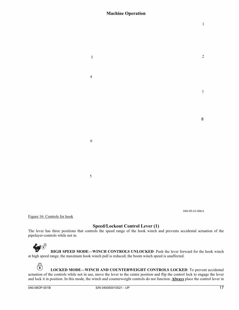
Figure 16: Controls for hook
Speed/Lockout Control Lever (1) The lever has three positions that controls the speed range of the hook winch and prevents accidental actuation of the pipelayer-controls while not in.
HIGH SPEED MODE—WINCH CONTROLS UNLOCKED: Push the lever forward for the hook winch at high speed range, the maximum hook winch pull is reduced; the boom winch speed is unaffected.
LOCKED MODE—WINCH AND COUNTERWEIGHT CONTROLS LOCKED: To prevent accidental actuation of the controls while not in use, move the lever to the centre position and flip the control lock to engage the lever and lock it in position. In this mode, the winch and counterweight controls do not function. Always place the control lever in
040-09-63-006A
3
4
1
2
5
8
6
7

040-08OP-001B S/N 040050010021 - UP
18
the LOCKED MODE and engage the Control Lock plate whenever the machine is left unattended, or when inadvertent control operation could result in a dangerous situation arising.
LOW SPEED MODE—WINCH CONTROLS UNLOCKED: Pull the lever back for the hook winch low speed range, maximum hook winch pull is available; standard boom winch speed unaffected.
Speed/Lockout Control Lock (2) Use the speed/lockout control lock lever (2) to lock the speed/lockout control lever (1) in the LOCKED MODE position. Move the boom control lever to HOLD position. Move the hook control lever to HOLD position. Move the speed/lockout control lever to the centre position. Flip the lock over the control lever in order to lock the lever in the LOCKED MODE position. This locks the boom controls and the hook controls in HOLD in order to prevent accidental boom movement or hook movement. Flip lock lever away from the control lever in order to allow actuation of the speed/lockout control lever. Move the speed/lockout control lever to the desired speed range in order to operate the winches. Always move the speed control lever to the "LOCKED" position before shutting off the engine or immediately after the engine quits running to prevent unintentional load release or, after the engine is restarted, drawworks operation.
Hook Control (3)
HOLD: The lever self centres to this position whenever it is released. In this position, the load winch brake will set, and the hook will stop and remain at the position it is in.
Quick Drop - Move the hook control lever to this position in order to allow the hook to fall freely. When the hook control lever is released, the lever returns to the HOLD position. The hook will remain in place. NOTE: Quick drop is only available in HIGH or LOW SPEED mode�Winch Controls Unlocked.
LOWER: Move the lever to this position to lower the hook with controlled winch power. The further the lever is pushed away from HOLD, the faster the hook will lower. The closer the lever is toward HOLD, the slower the hook will lower. When the lever is released, it will return to the HOLD position, the winch brake will set, and the hook will stop and remain at the position it is in. Hook winch line speed varies with engine throttle setting. Hook control is smoothest at engine speeds faster than idle.
RAISE: Move the lever to this position to raise the hook. The further the lever is pulled away from "HOLD", the faster the hook will raise. The closer the lever is toward "HOLD", the slower the hook will raise. When the lever is released, it will return to the "HOLD” position, and the hook will stop and remain at the position it is in. Hook winch line speed varies with engine throttle setting. Hook control is smoothest at engine speeds faster than idle. NOTE: The hydraulic implement system and some machine controls are "LIVE" for as long as the accumulator holds a charge, even if the engine is not running. This pressure charge will take approximately four hours or more to bleed off.
Accumulator - Relieving Charge To relieve the accumulator charge, with no load on the hook and the engine stopped, move the hook control lever from "HOLD" to "RAISE" 10 times.

040-08OP-001B S/N 040050010021 - UP
19
Boom Control (4)
A) HOLD: The lever self centres to this position whenever it is released. In this position, the boom winch brake will set, and the boom will stop and remain at the position it is in.
B) LOWER: Move the lever to this position to lower the boom. The further the lever is pushed away from HOLD, the faster the boom will lower. The closer the lever is toward HOLD, the slower the boom will lower. When the lever is released, it will return to the HOLD position, and the boom will stop and remain at the position it is in. Boom winch line speed varies with engine throttle setting. Boom control is smoothest at engine speeds faster than idle.
C) RAISE: Move the lever to this position to raise the boom. The further the lever is pulled away from HOLD, the faster the boom will raise. The closer the lever is toward HOLD, the slower the boom will raise. When the lever is released, it will return to the HOLD position, and the boom will stop and remain at the position it is in. Boom winch line speed varies with engine throttle setting. Boom control is smoothest at engine speeds faster than idle.
Counterweight Control (5)
Hold - When the operator releases the counterweight control lever from any position, the lever will return to the HOLD and the counterweight will remain in position.
Out - Move the counterweight control lever to this position in order to move the counterweight outward. When the counterweight control lever is released, the lever returns to the HOLD position and the counterweight will remain in position. Refer to the Operation and Maintenance Manual, "Counterweight Lock Lever" for the procedure to lock the counterweight in the fully extended position.
In - Move the counterweight control lever to this position in order to move the counterweight inward. When you release the counterweight control lever the lever returns to the HOLD position and the counterweight will remain in position.
Counterweight Control Lock (6) Use the counterweight control lock lever (6) to lock the counterweight control lever (5) in the HOLD position. Move the counterweight control lever to the HOLD position. Flip lock lever inward in order to lock the lever in the HOLD position. Lock the counterweight control lever in HOLD in order to avoid accidental actuation of the counterweight while the use of the winches is required. Flip lock lever to the outward position in order to allow actuation of the counterweight control lever.
ENGINE SPEED SWITCH RELOCATED (7) NOTE: New location of this tractor's control, refer to the tractors operation and maintenance manual for correct operation.
HORN LOCATION MOVED (8) NOTE: New location of this tractor's control, refer to the tractors operation and maintenance manual for correct operation.

040-08OP-001B S/N 040050010021 - UP
20
Counterweight Lock Lever
Crushing Hazard! When the counterweight is in the fully extended position for servicing the machine, secure the extended counterweight with the counterweight lock lever. Use the counterweight lock lever to avoid possible personnel injury or death from crushing. Figure 17: Counterweight lock lever
NOTICE When you engage the locking device for the counterweight or when you disengage the locking device for the counterweight use the Counterweight Control Lock lever for the controls. Lock the controls in HOLD in order to avoid the inadvertent movement of the boom or the hook. Refer to the topic "Counter Control Lock" in the Operation and Maintenance Manual, "Operator Controls". Lock the counterweight when you service the machine. Locked - Extend counterweight cylinders to maximum length Engage the locking lever (1). Retract the counterweight until there is pressure on the locking lever (1). Unlocked - Extend counterweight cylinders to maximum length. Disengage the locking lever (1). Retract the counterweight. The locking mechanism will hold the counterweight in position in the event of a hydraulic failure. Transportation Information
Removal of the Boom
Figure 18: Removal of the boom

040-08OP-001B S/N 040050010021 - UP
21
1. Lower the boom for removal of the load sheave block.
Figure 19: Removal of boom, steps 1, 2, 3
2. Remove cotter pin (1), retainer (2), and pin (3). Lower the load sheave blocks to the ground. Reinstall the pins and the retainer in the boom. The weight of the upper load sheave block is approximately 42 kg (92 lb). The weight of the lower load sheave block is approximately 39 kg (85 lb).
3. Draw in the load cable in order to pull the sheave blocks to the machine. Fasten the sheave blocks to the machine for shipping.
Figure 20: Removal of boom, steps 4, 5, 6
4. Raise the boom to the horizontal position. Block up the boom. Remove cotter pin (4), retainer (5), and pin (6). Reinstall the pins and the retainer in the boom. The weight of the boom sheave block is 27 kg (60 lb).
5. Draw in the cable for the boom in order to pull the sheave block to the machine Fasten the sheave block to the machine for shipping.
040-20-30-002A
4, 5, 6
040-20-30-003A
1, 2, 3

040-08OP-001B S/N 040050010021 - UP
22
Figure 21: Location of pins for removal of boom
6. Attach an appropriate lifting device to the boom. Remove the pins from the track roller frame and lift the boom from the machine. The weight of the boom is 676 kg (1490 lb). Replace the pins in the track roller frame.
Maintenance and Lubrication Section Lubricant Viscosities
General � Follow tractor manufacture's maintenance and lubrication instructions for tractor service as required. � Follow tractor and/or winch manufacture’s lubrication instructions for the pipelayer hydraulic system. � To prevent corrosion damage to the winch interiors, if not used regularly, cycle the winches up and down several times
at least once every two weeks.
Selecting the Viscosity The proper oil viscosity grade is determined by the minimum outside temperature. This is the temperature when the machine is started and when the machine is operated. In order to determine the proper oil viscosity grade, refer to the "Min" column in the table. This information reflects the coldest ambient temperature condition for starting a cold machine and for operating a cold machine. Refer to the "Max" column in the table in order to select the oil viscosity grade for operating the machine at the highest temperature that is anticipated. Use the highest oil viscosity that is allowed for the ambient temperature when you start the machine. Machines that are operated continuously should use oils that have the higher oil viscosity in the final drives and in the differentials. The oils that have the higher oil viscosity will maintain the highest possible oil film thickness. Consult your dealer if additional information is needed.
040-17-20-001A

040-08OP-001B S/N 040050010021 - UP
23
Lubricant Viscosities for Ambient Temperatures Lubricant Viscosities for Ambient Temperatures
Compartment or System Oil Type and Classification Oil Viscosities °C °F Min Max Min Max
Hydraulic System
Caterpillar HYDO Caterpillar DEO SAE 0W20 -40 40 -40 104
Caterpillar TDTO SAE 0W30 -40 40 -40 104 Caterpillar MTO SAE 5W30 -30 40 -22 104
Global DHD-1 SAE 5W40 -30 40 -22 104 API CH-4 SAE 10W -20 40 -4 104 API CG-4 SAE 30 10 50 50 122 API CF-4 SAE 10W30 -20 40 -4 104 API CF SAE 15W40 -15 50 5 122
commercial TO-4 Caterpillar MTO -25 40 -13 104 Caterpillar TDTO-TMS Biodegradable
Caterpillar Biodegradable Hydraulic Oil -40 43 -40 110 Hydraulic Oil (HEES) (1) HEES (4)
commercial BF-1 (1) TDTO-TMS (2) -20 50 -4 122 Boom winch gear train SAE 80W90 -30 +50 -22 +122
Table 4: Lubricant viscosities for ambient temperature
(1) Commercial Biodegradable Hydraulic Oil (HEES) must meet the Caterpillar BF-1 specification.
Capacities (Refill) APPROXIMATE REFILL CAPACITIES
Compartment or System Liters US gal
Imperial gallon
Hydraulic Oil Tank 37.5 9.9 8.2
Boom Winch 5.7 1.5 1.3 Table 5: Lubricant refill capacities
S-O-S Information S O S Services is a highly recommended process for Caterpillar customers to use in order to minimize owning and operating cost. Customers provide oil samples, coolant samples, and other machine information. The dealer uses the data in order to provide the customer with recommendations for management of the equipment. In addition, S O S Services can help determine the cause of an existing product problem. Refer to Caterpillar Special Publication, SEBU6250, “Caterpillar Machine Fluid Recommendations” for detailed information concerning S O S Services. Refer to the Operation and Maintenance Manual, “Maintenance Interval Schedule” for a specific sampling location and a service hour maintenance interval. Consult your dealer for complete information and assistance in establishing an S-O-S program for your equipment.
Maintenance Interval Schedule (MIS) Ensure that all safety information, warnings, and instructions are read and understood before any operation or any maintenance procedures are performed. The user is responsible for the performance of maintenance, including all adjustments, the use of proper lubricants, fluids, filters, and the replacement of components due to normal wear and aging. Failure to adhere to proper maintenance intervals and procedures may result in diminished performance of the product and/or accelerated wear of components. Use mileage, fuel consumption, service hours, or calendar time, WHICH EVER OCCURS FIRST, in order to determine the maintenance intervals. Products that operate in severe operating conditions may require more frequent maintenance. Note: Before each consecutive interval is performed, all maintenance from the previous interval must be performed.

040-08OP-001B S/N 040050010021 - UP
24
When Required � Boom Line – Install � Hook Load Line – Install
Every 10 Service Hours or Daily � Controls for proper operation of boom and hook– Check � Boom cut-out operation – Check � Boom Pivot Pins – Lubricate � Counterweight Cylinder Bearings – Lubricate � Counterweight Hinge Pins – Lubricate � Fairlead Sheave – Lubricate � Hook and Wire Cable – Inspect � Hydraulic System Oil Level – Check � Hoses and fittings for leaks – Check � Sheave Block Bearings – Lubricate � Pipelayer structures and components for loose bolts, cracks, damage, etc. – Inspect � Inspect the hook for any distortion, bends, twists, etc. Inspect the hook for any wear, cracks, nicks, or gouges. Refer to
American National Standard Institute ANSI/ASME B30.14 � Blocks, and yokes for wear or damage – Inspect � Ensure that area between tractor tracks and pipelayer-tractor attachment structures are free from dirt, debris, ice, snow, etc. –
Inspect
Every 50 Service Hours or Weekly � Thoroughly check boom cut-out system operation and adjustment, lubricate cut-out valve roller and actuator. � Lightly lubricate wire rope with recommended engine or hydraulic oil.
Every 500 Service Hours � Final Drive Oil Sample - Obtain � Hydraulic System Oil Sample - Obtain � Transmission System Oil Sample - Obtain
Every 500 Service Hours or 3 Months � Hydraulic System Oil Filter - Replace
Every 2000 Service Hours or 1 Year � Boom Winch gear train Oil - Change � Hydraulic System Oil - Change
Accumulator
This system contains high pressure gas. Failure to follow the instructions and warnings could cause an explosion, resulting in possible injury or death. Do not expose to fire. Do not weld. Do not drill. Do not remove any hydraulic system lines, taps or parts until pressure has been relieved. Relieve pressure before discharging. See Operation and Maintenance Manual "Accumulator - Relieving Charge". See Operation and Maintenance Manual "Accumulator" for charging and discharging. See your Dealer for tools and detailed information. Accumulator must be charged with dry nitrogen (N2) gas by qualified personnel only. Charge the accumulator to 3445 kPa (500 PSI).
040-08OP-001B S/N 040050010021 - UP
25
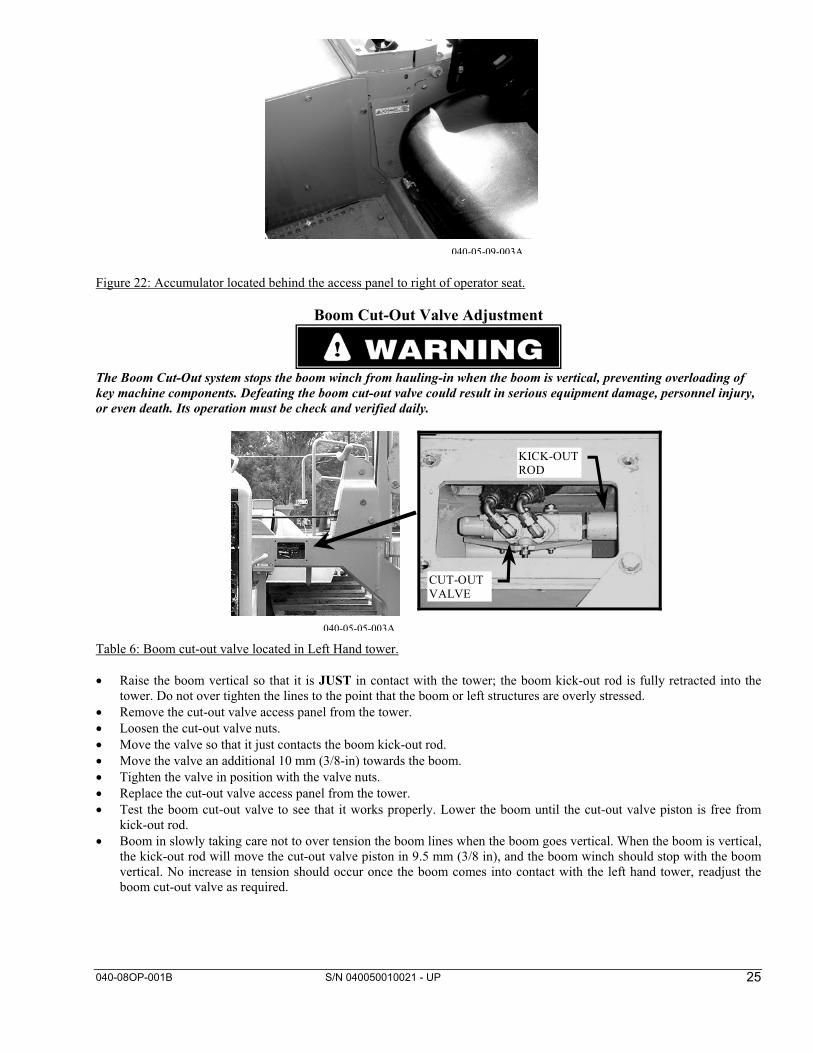
Figure 22: Accumulator located behind the access panel to right of operator seat.
Boom Cut-Out Valve Adjustment
The Boom Cut-Out system stops the boom winch from hauling-in when the boom is vertical, preventing overloading of key machine components. Defeating the boom cut-out valve could result in serious equipment damage, personnel injury, or even death. Its operation must be check and verified daily.
KICK-OUTROD
CUT-OUTVALVE
Table 6: Boom cut-out valve located in Left Hand tower. � Raise the boom vertical so that it is JUST in contact with the tower; the boom kick-out rod is fully retracted into the
tower. Do not over tighten the lines to the point that the boom or left structures are overly stressed. � Remove the cut-out valve access panel from the tower. � Loosen the cut-out valve nuts. � Move the valve so that it just contacts the boom kick-out rod. � Move the valve an additional 10 mm (3/8-in) towards the boom. � Tighten the valve in position with the valve nuts. � Replace the cut-out valve access panel from the tower. � Test the boom cut-out valve to see that it works properly. Lower the boom until the cut-out valve piston is free from
kick-out rod. � Boom in slowly taking care not to over tension the boom lines when the boom goes vertical. When the boom is vertical,
the kick-out rod will move the cut-out valve piston in 9.5 mm (3/8 in), and the boom winch should stop with the boom vertical. No increase in tension should occur once the boom comes into contact with the left hand tower, readjust the boom cut-out valve as required.
040-05-05-003A
040-05-09-003A

040-08OP-001B S/N 040050010021 - UP
26
Boom Line – Install
Personal injury or death can result from worn wire rope cable. Worn or frayed cable could break causing injury. Check the wire rope cable. If cable is worn or is frayed install new cable. Wear gloves when handling the wire rope cable. Note: Make sure that the construction of the wire rope is 6x37 IWRC XIPS (Independent Wire Rope Core, eXtra Improved Plow Steel). Also, the established grade of the wire rope is the improved plow bolt (steel), 18 700 kg (41,200 lb) minimum breaking strength.
SPECIFICATIONS (WIRE ROPE) Cable Diameter Length
Boom Line 15.88 mm
(0.625 inch) 29.3 m (96 feet)
Table 7: Boom line wire rope specifications Weld the cable ends in order to prevent fraying.
1. Lower the boom to the ground and support the boom.
2. Disconnect the cable from the drum for the boom.
3. Unroll the new cable from the spool. Note: Unroll all of the cable from the spool. Lay the wire rope on a flat surface. Never lift the wire rope off the spool in coils.
Figure 23: Installing boom line, cable anchor assembly
4. Install the cable (1) into the small slot and through the larger slot in the drum for the boom.
a. Make sure that 2 to 4 threads of capscrew (2) are engaged into cable anchor assembly (4). Start with the capscrew and insert the cable anchor assembly into the longer slot as far as allowed.
b. Make sure that the lip of retainer (3) faces the top edge (5) of the small slot in order to hold the retainer in
place. Make a loop with the cable end and insert the cable end into the slot past the cable anchor assembly.

040-08OP-001B S/N 040050010021 - UP
27
c. Pull the cable until the cable and anchor assembly are securely seated inside the slot. Tighten the capscrew to a
torque (6) of 44 ± 3N·m (32 ± 2 lb ft).
5. Wind one half of the cable on the drum (7.) Wind the cable evenly across the drum.
View from the front of the machine Figure 24: Installing boom line
6. Install the boom line from the winch to the boom in the following manner:
a. Install the cable from winch drum (1) to upper sheave block (2). Install the cable over the sheave.
b. Route the cable to upper fairlead sheave (3). Install the cable under the sheave and around the sheave.
c. Insert the cable upward into pocket (4) around the wedge. Then, insert the cable downward through the pocket.
d. Install the nuts, bolts, and clamp (5) and secure the cable in place.
Boom Pivot Pins - Lubricate
Figure 25: Boom pivot pins, grease fittings The grease fittings for lubricating the boom pivot pins are located on the left side of the machine. Each boom pivot pin has a grease fitting on the end. Lubricate the boom pivot pins through the two fittings.

040-08OP-001B S/N 040050010021 - UP
28
Counterweight Cylinder Bearings - Lubricate
Figure 26: Counterweight cylinder bearings fittings location The fittings for the counterweight cylinder bearings are located on the right side of the machine.
Figure 27: Counterweight cylinder bearings location Lubricate the counterweight cylinder bearings through the fittings that are at both ends of the counterweight cylinder.
Counterweight Hinge Pins - Lubricate
Figure 28: Counterweight hinge pins located right side of machine
040-09-68-004A
040-08OP-001B S/N 040050010021 - UP
29
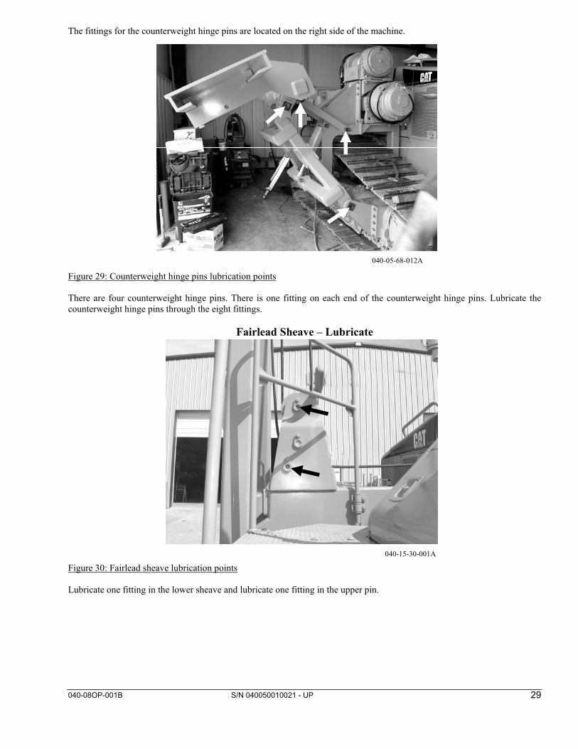
The fittings for the counterweight hinge pins are located on the right side of the machine.
Figure 29: Counterweight hinge pins lubrication points There are four counterweight hinge pins. There is one fitting on each end of the counterweight hinge pins. Lubricate the counterweight hinge pins through the eight fittings.
Fairlead Sheave – Lubricate
Figure 30: Fairlead sheave lubrication points Lubricate one fitting in the lower sheave and lubricate one fitting in the upper pin.
040-05-68-012A
040-15-30-001A

040-08OP-001B S/N 040050010021 - UP
30
Hook Load Line – Install
Personal injury or death can result from worn wire rope cable. Worn or frayed cable could break causing injury. Check the wire rope cable. If cable is worn or is frayed install new cable. Wear gloves when handling the wire rope cable. Note: Make sure that the construction of the wire rope is 6x37 IWRC XIPS (Independent Wire Rope Core, eXtra Improved Plow Steel). Also, the established grade of the wire rope is the improved plow bolt (steel), 18 700 kg (41,200 lb) minimum breaking strength.
SPECIFICATIONS (WIRE ROPE) Cable Diameter Length
Hook Load Line 15.88 mm
(0.625 inch) 39.62 m
(130 feet) Table 8: Hook load line wire rope specifications Weld the ends of the cable in order to prevent fraying.
1. Lower the boom to the horizontal position.
2. Unwind the cable.
3. Disconnect the cable from the load drum. Note: Unroll all of the cable from the spool. Lay the wire rope on a flat surface. Never lift the wire rope off the spool in coils.
Figure 31: Installing hook load line, cable anchor assembly
4. Install the cable (1) into the small slot and through the larger slot in the drum for the boom.
a. Make sure that 2 to 4 threads of capscrew (2) are engaged into cable anchor assembly (4). Start with the capscrew and insert the cable anchor assembly into the longer slot as far as allowed.
b. Make sure that the lip of retainer (3) faces the top edge (5) of the small slot in order to hold the retainer in
place. Make a loop with the cable end and insert the cable end into the slot past the cable anchor assembly.

040-08OP-001B S/N 040050010021 - UP
31
c. Pull the cable until the cable and anchor assembly are securely seated inside the slot. Tighten the capscrew to a torque (6) of 44 ± 3N·m (32 ± 2 lb ft).
5. Wind one half of the cable evenly across the load drum (7).
View from the front of the machine
Figure 32: Installing hook load line
6. Install the hook load line from the winch drum onto the sheave blocks in the following manner:
a. Install the cable from winch drum (1) under lower fairlead sheave (2).
b. Route the cable to upper sheave block. Install the cable over sheave (3). Sheave (3) is toward the front of the machine.
c. Install the cable around sheave (4) in the lower sheave block.
d. Route the cable to the upper sheave block again and install the cable over sheave (5). Sheave (5) is toward the
rear of the machine.
e. Insert the cable downward into the pocket (6) and around the wedge. Then, pull the cable end upward through the pocket.
f. Install the nuts, bolts, and clamp (7) and secure the cable in place.
Hook and Wire Cable – Inspect
Inspect the Hook
Inspect the hook frequently. The inspections should include observation of the hook during operation of the hook. A designated person determines if the conditions that are found during the inspections constitute a hazard. The designated person will determine if a more detailed inspection is required.
� Inspect the hook for any distortion such as bends in the hook or twists in the hook. � Inspect the hook for any wear. � Inspect the hook for cracks, nicks, or gouges. � If a latch is provided, inspect the latch. Make sure that the latch engages properly. Inspect the latch for any damage.
Make sure that the latch is not malfunctioning. � Inspect the hook assembly and the means for securing the hook assembly. � For additional information on the proper maintenance and on the proper inspection of hooks, refer to "American
National Standard Institute ANSI/ASME B30.14".

040-08OP-001B S/N 040050010021 - UP
32
Inspect Wire Cable Make a visual inspection of all running cables that are in continuous use. Make the inspection of the running cables on a daily basis before the machine is placed in operation. Inspect all of the cables on a monthly basis. All inspections shall be performed by a designated person. Keep a dated report of the condition of the cable on file in a location that is available to designated personnel. Perform a close inspection of the sections of the cable that are normally hidden during the visual inspection and the maintenance inspection. (This includes the sections of the cable that pass over the sheaves.) These points are the sections of the cable that are most likely to fail. Note any deterioration that results in a notable loss of the original strength. (See the conditions that are described below.) Determine if further use of the cable will constitute a hazard. Inspect the cable on a daily basis for the following conditions: � Inspect the cable for a reduction in the diameter of the cable below the nominal diameter. A loss of support in the cored
wire of the cable may be caused by internal corrosion, external corrosion, or wear of the outside wires. � Inspect the cable for broken outside wires. Check for the degree of distribution of the broken outside wires. Check for the
concentration of outside broken wires. � Inspect the cable for worn outside wires. � Inspect the cable for corroded wires and for broken wires at the connection on the wire cable end. � Inspect the cable end for connections that are corroded, cracked, bent, worn, or improperly installed. � Inspect the cable for sections that are crushed or kinked and for any loose wire strands. Excessive wear or broken wires may occur in sections of the cable that are in contact with saddles, equalizer sheaves, or other sheaves. Excessive wear or broken wires can also occur when cable travel is limited. Take care to inspect the ropes at these locations. When a machine is shutdown for a month or more, inspect all of the cables thoroughly. When a side boom machine has been in storage for a month or more, inspect all of the cables thoroughly. The inspection should be completed before the machine is returned to operation. The inspection should be for all types of deterioration. The inspection should be performed by a designated person or by an authorized person. The authorized person's approval is required for further use of the cable. A dated report on the condition of the cable should be kept on file. Take care in the inspection of cable that is resistant to rotation. Any new poured socket or swaged socket assembly that is used as a standing cable (guy) shall be proof tested. Test the cable to the lift capacity of the side boom machine or to the manufacturer's recommendation. Never give the cable a rating that is greater than 50 percent of the wire rope's nominal strength or of the structural strand's nominal strength. Note: For additional information on the proper maintenance and on inspection of the cable, refer to "American National Standards Institute ANSI/ASME B30.14".

040-08OP-001B S/N 040050010021 - UP
33
Hydraulic System Oil - Change Note: The normal hydraulic oil change interval is at every 2000 Service Hours or 1 Year. By performing S.O.S oil analysis, the hydraulic oil change interval may be extended to 4000 Service Hours. S.O.S oil analysis must be performed at every 500 Service Hours or 3 Months in order to extend the hydraulic oil change interval. The results from the S.O.S oil analysis will determine if the hydraulic oil change interval may be extended. If S.O.S oil analysis is not available, the hydraulic oil change interval must remain at every 2000 Service Hours or 1 Year . Refer to the Operation and Maintenance Manual, "Hydraulic System Oil Sample - Obtain". Machines that are used in severe conditions are not included in the 4000 hour maintenance interval. Machines that are used in severe conditions must use the interval in the Maintenance Interval Schedule.
At operating temperature, the hydraulic tank is hot and under pressure. Hot oil and components can cause personal injury. Do not allow hot oil or components to contact skin. Remove the filler cap only when the engine is stopped, and the filler cap is cool enough to touch with your bare hand. Remove the filler cap slowly in order to relieve pressure.
Lubricants Approved hydraulic oil must be used to obtain the 4000 hour hydraulic oil change Refer to the list that follows for approved oils.
Caterpillar Hydraulic Oils � "Cat HYDO" � TDTO � TDTO (TMS) � DEO � Hydraulic environmental ester synthetic (HEES) � MTO
Commercial Oils Diesel engine oils (Heavy Duty) with a minimum zinc content of 900 ppm can be used. Acceptable commercial oils are identified by the American Petroleum Institute trademark ("API"). Refer to the list that follows for acceptable types of hydraulic oils. � CF � CF-4 � CG-4 � CH-4 Note: Industrial hydraulic oils are not recommended for the hydraulic systems of Caterpillar machines nor for Vanguard Equipment installed attachments. Industrial hydraulic oils are more likely to allow corrosion and industrial hydraulic oils are more likely to allow excessive wear.

040-08OP-001B S/N 040050010021 - UP
34
Change the Hydraulic Oil Operate the machine in order to warm the oil. Park the machine on level ground. Engage the parking brake and stop the engine.
Figure 33: Hydraulic tank filler cap 1. Remove the hydraulic tank filler cap slowly in order to relieve any pressure. 2. Remove the retainer ring from the oil filler tube. 3. Remove the strainer from the oil filler tube. 4. Wash the filler strainer and the filler cap in a clean nonflammable solvent.
Figure 34: Oil drain plug 5. Remove the oil drain plug. The oil drain plug is located under the right rear corner of the machine. 6. Attach a hose to a 1 inch NPT pipe nipple. This 1 inch NPT pipe nipple should have a length of 100 mm (4 inch). 7. Install the pipe nipple into the drain plug opening. 8. Rotate the pipe nipple clockwise in order to open the internal drain valve. Allow the oil to drain into a suitable
container; refer to Operation and Maintenance Manual "Capacities (Refill)" in the "Maintenance and Lubrication Section".
9. Remove the pipe nipple. The valve for the hydraulic tank will close. 10. Clean the drain plug and install the drain plug. Tighten the drain plug to a torque of 68 ± 7 N·m (50 ± 5 lb ft). 11. See Operation and Maintenance Manual, "Hydraulic System Oil Filter - Replace". Change the hydraulic system filter. 12. Install the filler strainer and the retainer ring. 13. See Operation and Maintenance Manual, "Capacities (Refill)" in order to determine the amount of hydraulic oil that is
needed to fill the hydraulic oil tank Fill the hydraulic oil tank with the appropriate oil. 14. Inspect the filler cap gasket. Replace the gasket if damage or wear is evident.

040-08OP-001B S/N 040050010021 - UP
35
15. Install the filler cap. 16. Start the engine. Run the engine for a few minutes.
Figure 35: Oil level sight gauge 17. Maintain the oil level to the "FULL" mark in the sight gauge. Add oil, if necessary. 18. Stop the engine. Reference: See Special Publication, SEBU6250, "Caterpillar Mac tine Fluid Recommendations", "Sampling Interval Schedule and Location of Sampling Valve" and Special Publication, SEBU6250, "Caterpillar Machine Fluid Recommendations", "S O S Oil Analysis" for additional information.
Hydraulic System Oil Filter - Replace
At operating temperature, the hydraulic tank is hot and under pressure. Hot oil and components can cause personal injury. Do not allow hot oil or components to contact skin. Remove the filler cap only when the engine is stopped, and the filler cap is cool enough to touch with your bare hand. Remove the filler cap slowly in order to relieve pressure.
NOTICE Care must be taken to ensure that fluids are contained during performance of inspection, maintenance, testing, adjusting and repair of the product. Be prepared to collect the fluid with suitable containers before opening any compartment or disassembling any component containing fluids. Refer to Special Publication, NENG2500, "Caterpillar Tools and Shop Products Guide" for tools and supplies suitable to collect and contain fluids on Caterpillar Products. Dispose of all fluids according to local regulations and mandates.
Figure 36: Hydraulic tank filler cap Refer to the tractor’s operation manual for the specific procedures regarding Hydraulic System Oil Filter - Replace.

040-08OP-001B S/N 040050010021 - UP
36
Hydraulic System Oil Level – Check
Figure 37: Hydraulic tank The hydraulic tank is on the right rear corner of the machine.
Figure 38: Oil level sight gauge 1. Maintain the oil level to the “Full” mark in the sight gauge. 2. If the hydraulic system requires additional hydraulic oil, add oil as per the instructions in the tractor’s operation manual
"Hydraulic System Oil Level – Check" section 3. Clean the filler cap and install the filler cap.
Hydraulic System Oil Sampling Refer to the tractor’s operation manual for the specific procedures regarding Hydraulic System Sampling.
Sheave Block Bearing – Lubricate
Figure 39: Boom sheave block grease nipple Lubricate one fitting in the boom sheave block.
040-20-30-002A

040-08OP-001B S/N 040050010021 - UP
37
Figure 40: Lower load sheave block grease nipple Lubricate two fittings in the lower load sheave block.
Figure 41: Upper load sheave block grease nipple Lubricate two fittings–one on each side of the block–in the upper load sheave block.
040-20-30-003A
040-20-30-003A