Embed Size (px)
Citation preview
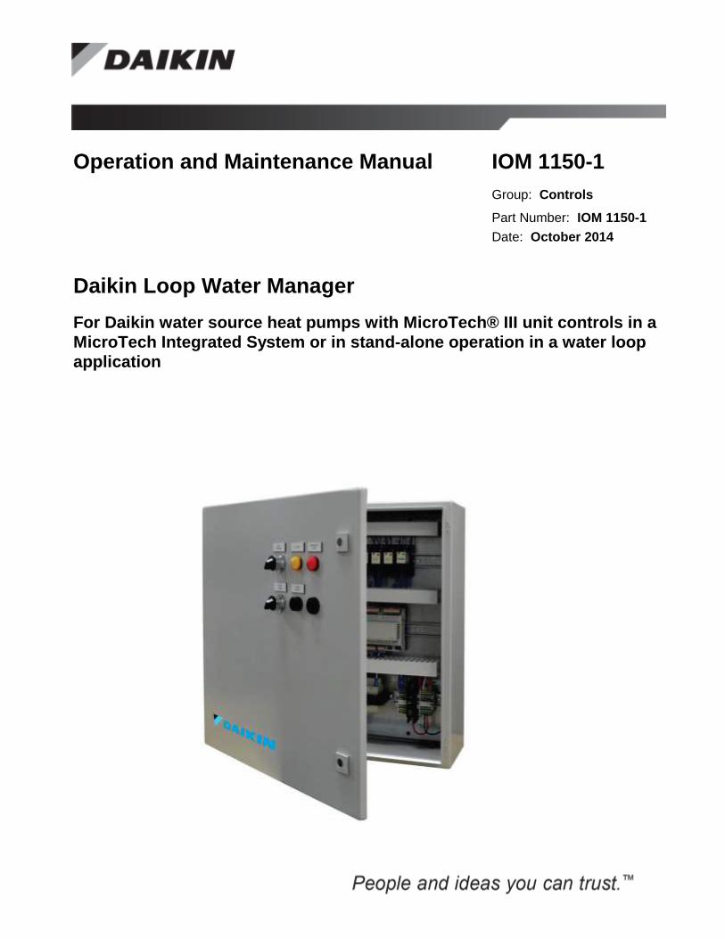
Operation and Maintenance Manual IOM 1150-1
Group: Controls
Part Number: IOM 1150-1
Date: October 2014
Daikin Loop Water Manager
For Daikin water source heat pumps with MicroTech® III unit controls in a
MicroTech Integrated System or in stand-alone operation in a water loop
application

IOM 1150-1 • LOOP WATER MANAGER 2 http://www.DaikinApplied.com
Table of Contents
Table of Contents ..................................................................................................................................................... 2 Figures ..........................................................................................................................................................................................5 Revision History ...........................................................................................................................................................................6 Reference Documents ...................................................................................................................................................................6 Limited Warranty .........................................................................................................................................................................6 Introduction .............................................................................................................................................................. 7 Hazard Identification Messages ...................................................................................................................................................7 Description ................................................................................................................................................................ 8 Model Number Nomenclature ................................................................................................................................. 9 Hardware Installation Process .............................................................................................................................. 10 Loop Water Manager Wiring Diagrams ................................................................................................................ 11
Wiring for Loop Water Manager models LWM662, LWM084, LWM226 ...........................................................................11 Wiring for Loop Water Manager models LWM662, LWM084, LWM226 (continued) ........................................................12 Wiring for Loop Water Manager models LWM662, LWM084, LWM226 (continued) ........................................................13 Wiring for Loop Water Manager models LWM084 and LWM226 only ...............................................................................14 Wiring for Loop Water Manager model LWM226 only ........................................................................................................15
Field Wiring ............................................................................................................................................................. 16 Field Analog Output Signals ......................................................................................................................................................16
Boiler Valve ...........................................................................................................................................................................16 Tower Fan ..............................................................................................................................................................................16
Field Analog Input Signals .........................................................................................................................................................17 Water Loop Supply Temp ......................................................................................................................................................17 Outdoor Air Temperature .......................................................................................................................................................17 Water Loop Return Temperature............................................................................................................................................17 Tower Supply Temperature ....................................................................................................................................................17 Tower Return Temperature ....................................................................................................................................................18 Head Pressure .........................................................................................................................................................................18 Outdoor Air Humidity ............................................................................................................................................................18 Storage Tank Temperature .....................................................................................................................................................18 Boiler Supply Temperature ....................................................................................................................................................19 Boiler Return Temperature .....................................................................................................................................................19 Heat Exchanger Supply Temperature .....................................................................................................................................19 Heat Exchanger Return Temperature .....................................................................................................................................19 Geothermal Temperature ........................................................................................................................................................20
Field Digital Outputs Signals .....................................................................................................................................................20 Alarm LED Output .................................................................................................................................................................20 Emergency Stop LED .............................................................................................................................................................20 External Schedule 1-6 ............................................................................................................................................................21 Loop Pump 1 & 2 ...................................................................................................................................................................21 Secondary Pump 1 & 2 ...........................................................................................................................................................22 Tower Fan Enable ..................................................................................................................................................................22 Cooling Stage 1-12 .................................................................................................................................................................23 Sump Dump Output ................................................................................................................................................................24 Heating Stage 1-12 .................................................................................................................................................................25
Field Digital Input Signals..........................................................................................................................................................25 Loop Flow Switch 1 & 2 ........................................................................................................................................................25 Secondary Flow Switch 1 & 2 ................................................................................................................................................26 Damper Interlock ....................................................................................................................................................................26 External Flow Request ...........................................................................................................................................................26 Emergency Stop Input ............................................................................................................................................................26
Hardware ................................................................................................................................................................. 27 Main Controller ..........................................................................................................................................................................27
Inputs/Outputs ........................................................................................................................................................................27 Expansion Modules ....................................................................................................................................................................28
DIP Switch Configuration ......................................................................................................................................................29
IOM 1150-1 • LOOP WATER MANAGER 3 http://www.DaikinApplied.com
Light Emitting Diodes (LEDs) ...............................................................................................................................................30 Expansion Module A ..............................................................................................................................................................31 Expansion Module B ..............................................................................................................................................................31 Expansion Module C ..............................................................................................................................................................32
Field Temperature Sensors .........................................................................................................................................................33 Using the Keypad/Display ..................................................................................................................................... 34 Passwords ...................................................................................................................................................................................34 Navigation Mode ........................................................................................................................................................................35 Edit Mode ...................................................................................................................................................................................35 Unit Support ...............................................................................................................................................................................35 Software Startup Process ..................................................................................................................................... 36 Unit Configuration .....................................................................................................................................................................36
Radiant Loop App ..................................................................................................................................................................36 Main Loop Pumps ..................................................................................................................................................................36 Secondary Loop Pumps ..........................................................................................................................................................36 Main Loop Flow Switches ......................................................................................................................................................36 Secondary Loop Flow Switches .............................................................................................................................................36 Secondary Loop Pump 1 & 2 Function ..................................................................................................................................36 Available Heat Stages ............................................................................................................................................................37 Available Cool Stages ............................................................................................................................................................37 PreHeat/PreCool Enable .........................................................................................................................................................37 Boiler Valve Active ................................................................................................................................................................37 Boiler Output Type.................................................................................................................................................................37 Tower Fan Active ...................................................................................................................................................................37 Tower Output Type ................................................................................................................................................................37 Loop Return Sensor ................................................................................................................................................................37 Head Pressure Sensor .............................................................................................................................................................37 Head Pressure Sensor Type ....................................................................................................................................................37 Pressure Sensor Range ...........................................................................................................................................................37 Outside Air Humidity Sensor Enable .....................................................................................................................................37 Outside Air Humidity Sensor .................................................................................................................................................37 Sensor Enables .......................................................................................................................................................................37 Damper Interlock ....................................................................................................................................................................38 External Schedules .................................................................................................................................................................38 Staged Heating Outdoor Air Reset .........................................................................................................................................38 Boiler Valve Outdoor Air Reset .............................................................................................................................................38
Keypad/Display Menu Structure ........................................................................................................................... 39 Main Menu .................................................................................................................................................................................43 Quick Menu ................................................................................................................................................................................44
Unit Status/Settings Menu ......................................................................................................................................................46 Temperatures Menu ................................................................................................................................................................48
Main Loop Flow Control ............................................................................................................................................................49 Flow Status Menu ...................................................................................................................................................................49
Optional Tower or Boiler Valve Control....................................................................................................................................49 Tower Setpoint Menu .............................................................................................................................................................49 Tower Sump Dump Control ...................................................................................................................................................50 Boiler Setpoints Menu ............................................................................................................................................................51
Heat and Cool Stage Sequencing ...............................................................................................................................................52 Heat Rejection Spts Menu ......................................................................................................................................................53 Heat Addition Spts Menu .......................................................................................................................................................54
Pre-heating and Pre-cooling .......................................................................................................................................................55 PreHeat Activation .................................................................................................................................................................55 PreCool Activation .................................................................................................................................................................55 Pre Heat & Cool Menu ...........................................................................................................................................................56
Outside Air Setpoint Reset .........................................................................................................................................................57 Reset of Staged Heating Setpoints ..........................................................................................................................................57 Stg OA Reset Menu ................................................................................................................................................................57 Reset of Boiler Valve Setpoint ...............................................................................................................................................58

IOM 1150-1 • LOOP WATER MANAGER 4 http://www.DaikinApplied.com
BVlv OA Reset Menu ............................................................................................................................................................58 Pump Control Menu ...............................................................................................................................................................59 Date/Time/Schedules Menu ...................................................................................................................................................60
Commission Unit ........................................................................................................................................................................62 Timer Settings Menu ..............................................................................................................................................................62 Safety Setpoints Menu ............................................................................................................................................................62 The IP Setup Menu .................................................................................................................................................................63
Manual Control ..........................................................................................................................................................................64 Service Menus ............................................................................................................................................................................65 Unit Maintenance .......................................................................................................................................................................66 BMS Communications ...............................................................................................................................................................67 Unit Configuration .....................................................................................................................................................................68 Alarms ........................................................................................................................................................................................70
Alarm Clearing .......................................................................................................................................................................70 Fault Alarms (Highest Priority) ..............................................................................................................................................71 Problem Alarms (Medium Priority)........................................................................................................................................71 Warning Alarms (Lowest Priority) .........................................................................................................................................71
Emergency Control Activation ...................................................................................................................................................72 Emergency System Shutdown ....................................................................................................................................................72 About this LWM ........................................................................................................................................................................73 Unit State Transitions .................................................................................................................................................................73 BACnet Communication Module .......................................................................................................................... 75 Component Data .........................................................................................................................................................................75
Light Emitting Diodes (LEDs) ...............................................................................................................................................75 BACnet Network Connector ..................................................................................................................................................76 Board-To-Board Connector....................................................................................................................................................76
Installation ..................................................................................................................................................................................78 Contents of the BACnet Communication Module Kit ............................................................................................................78 Installing a new BACnet Communication Module .................................................................................................................78 Replacing an Existing BACnet Communication Module .......................................................................................................79
Integration ..................................................................................................................................................................................80 Connecting to the MicroTech Integrated System ............................................................................................... 81 Addressing ..................................................................................................................................................................................81 Configuring the BACnet Communication Module .....................................................................................................................81
BACnet IP Addressing ...........................................................................................................................................................81 Test Procedures ......................................................................................................................................................................83 BACnet MS/TP Addressing ...................................................................................................................................................83 Changing the MS/TP Data Transmission Rate .......................................................................................................................84 BACnet/MSTP Configurable Parameters ...............................................................................................................................85
Controller Application Software Upgrade Procedures ....................................................................................... 87 Upgrading Firmware or Application Software ...........................................................................................................................87 Troubleshooting Guide .......................................................................................................................................... 88 Service Information ................................................................................................................................................ 90 Test Procedures ..........................................................................................................................................................................90 Parts List ....................................................................................................................................................................................90

IOM 1150-1 • LOOP WATER MANAGER 5 http://www.DaikinApplied.com
Figures
Figure 1. LWM Model Number Nomenclature ............................................................................................................................9 Figure 2. Field power schematic.................................................................................................................................................10 Figure 3. Wiring diagram for all LWM ......................................................................................................................................11 Figure 4. Main Board Wiring Schematic ....................................................................................................................................12 Figure 5. Expansion Board A Wiring Schematic .......................................................................................................................13 Figure 6. Expansion Board B Wiring Schematic ........................................................................................................................14 Figure 7. Expansion Board C Wiring Schematic ........................................................................................................................15 Figure 8. Main Control Board ....................................................................................................................................................27 Figure 9. Expansion Modules .....................................................................................................................................................28 Figure 10. Expansion Module DIP Switches ..............................................................................................................................29 Figure 11. Keypad/Display Menu Structure (Main Menu) .........................................................................................................40 Figure 12. Keypad/Display Menu Structure (Page2) ..................................................................................................................41 Figure 13. Keypad/Display Menu Structure (Page 3) .................................................................................................................42 Figure 14. Example of Outside Air Setpoint Reset. ...................................................................................................................57 Figure 15. Boiler Valve OA Reset .............................................................................................................................................58 Figure 16. BACnet Communication Module Components. ........................................................................................................75 Figure 17. BACnet Communication Module and Knockout ......................................................................................................76 Figure 18. Diagram of Board to Board Connector .....................................................................................................................76
Figure 19. BACnet Communication Module with Board-to-Board Connector Inserted ............................................................77 Figure 20. Unit Controller MSTP Setup Screen – Change “ApplyMSTPChgs” ........................................................................84 Figure 21. Unit Controller MSTP Setup Screen - Change Baud Rate ........................................................................................82
Figure 22. SD Memory Card Slot ...............................................................................................................................................85
Figure 23. Service Button and BSP LED ...................................................................................................................................87

IOM 1150-1 • LOOP WATER MANAGER 6 http://www.DaikinApplied.com
Revision History
Number Date Type
IOM 1150 September 17, 2012 Initial release
IOM 1150-1 October 2014 Rewired some inputs and outputs to new locations on the terminal board, having all inputs
and outputs grouped together, respectively. Updated descriptions of many objects. Brand
renaming.
Reference Documents
Number Company Title Source
ED19015 Daikin Applied MicroTech III Loop Water Manager Protocol
Information for BACnet
www.DaikinApplied.com
OM 1092-2 Daikin Applied MicroTech Integrated System Manager operations
manual
www.DaikinApplied.com
ANSI/ASHRAE 135-
2008
American Society of
Heating, Refrigerating and
Air-Conditioning Engineers
BACnet® A Data Communication Protocol for
Building Automation and Control Networks
www.ashrae.org
Limited Warranty
Consult your local Daikin Applied Representative for warranty details. Refer to Form 933-43285Y. To find your local Daikin
Applied Representative, go to www.DaikinApplied.com.
NOTICE
Use this manual to install and configure the Daikin Loop Water Manager. Use the appropriate Daikin Engineering Data (ED) publication, known as the Protocol Information document, to integrate the unit into your network. The Protocol Information document contains addressing details, BACnet® protocol information, and a list of the data points available to the network. See the Reference Documents section of this manual for Protocol Information document numbers. MicroTech III control integration literature is available from your local Daikin sales representative and www.DaikinApplied.com.
Notice
Copyright © 2012 Daikin Applied, Minneapolis MN. All rights reserved throughout the world.
Daikin reserves the right to change any information contained herein without prior notice. The user is responsible
for determining whether this software is appropriate for his or her application.
® ™ The following are tradenames or registered trademarks of their respective companies: BACnet from the
American Society of Heating, Refrigerating and Air-Conditioning Engineers, Inc.; Windows from Microsoft
Corporation; Daikin McQuay, McQuay and MicroTech III from Daikin.
IOM 1150-1 • LOOP WATER MANAGER 7 http://www.DaikinApplied.com
Introduction
This document contains information related to the Daikin Loop Water Manager (LWM) for Daikin water source heat pumps
with MicroTech III unit controllers.
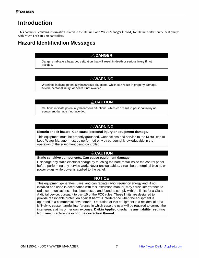
Hazard Identification Messages
! DANGER
Dangers indicate a hazardous situation that will result in death or serious injury if not avoided.
! WARNING
Warnings indicate potentially hazardous situations, which can result in property damage, severe personal injury, or death if not avoided.
! CAUTION
Cautions indicate potentially hazardous situations, which can result in personal injury or equipment damage if not avoided.
! WARNING
Electric shock hazard. Can cause personal injury or equipment damage.
This equipment must be properly grounded. Connections and service to the MicroTech III Loop Water Manager must be performed only by personnel knowledgeable in the operation of the equipment being controlled.
! CAUTION
Static sensitive components. Can cause equipment damage.
Discharge any static electrical charge by touching the bare metal inside the control panel before performing any service work. Never unplug cables, circuit board terminal blocks, or power plugs while power is applied to the panel.
NOTICE
This equipment generates, uses, and can radiate radio frequency energy and, if not installed and used in accordance with this instruction manual, may cause interference to radio communications. It has been tested and found to comply with the limits for a Class A digital device, pursuant to part 15 of the FCC rules. These limits are designed to provide reasonable protection against harmful interference when the equipment is operated in a commercial environment. Operation of this equipment in a residential area is likely to cause harmful interference in which case the user will be required to correct the
interference at his or her own expense. Daikin Applied disclaims any liability resulting
from any interference or for the correction thereof.

IOM 1150-1 • LOOP WATER MANAGER 8 http://www.DaikinApplied.com
Description
The Daikin Loop Water Manager (LWM) initiates and controls main and secondary flow pumps, as well as heat
addition/rejection outputs, to supply heat or cooling to the water loop for multiple zones of water source heat pumps, which will
in turn deliver climate control to their associated zones.
The Loop Water Manager can be ordered in a variety of hardware configurations to accommodate the site needs. See the Model
Number Nomenclature section and Hardware section to determine the inputs and outputs (I/O) available on your particular
model (Error! Reference source not found.).
One or two main pumps can be used in lead/lag mode or cycled based on operating hours. Each pump can have its own flow
switch or share the same switch. Secondary pumps can be configured for a secondary boiler or tower loop. You may have up to
two secondary loops and each one is equipped with a flow switch to verify pump operation. Alternatively, you may have
redundant secondary pumps operating on a single secondary loop.
Depending on model of the Loop Water Manager you have, you can have up to 12 cooling or heating stages. Each stage has its
own setpoint and deadband. There are also analog tower or boiler valve outputs to use with a variable heating element (boiler
valve or SCR electric) or cooling element (tower fan VFD or heat exchanger valve).
The LWM comes factory equipped with an alarm LED and audible alarm. It also has been equipped with a manual override
switch, emergency stop LED, and sump dump switch on the exterior of the panel.
The LWM can be capable of interfacing with a building automation system (BAS) or MicroTech Integrated System using
BACnet MS/TP (refer to model number, specifically the last two digits as indicated in the Model Nomenclature on page 9.)
A user’s building automation system or BAS will be able to connect directly to the LWM via twisted pair communication wire
in BACnet/MSTP networks and via an Ethernet cable in BACnet/IP networks. The contractor or network administrator will be
responsible for ensuring that the system’s performance is not altered.
IOM 1150-1 • LOOP WATER MANAGER 9 http://www.DaikinApplied.com
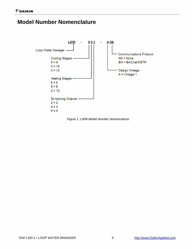
Model Number Nomenclature
Figure 1. LWM Model Number Nomenclature

IOM 1150-1 • LOOP WATER MANAGER 10 http://www.DaikinApplied.com
Hardware Installation Process
The Loop Water Manager is designed for indoor use only. The panel should be mounted on the interior surface of a convenient
sturdy wall with adequate clearance for door to swing.
The Loop Water Manager should be protected from direct sunlight, excessive moisture, dust or lint. The ambient environmental
temperature and humidity specifications for the panel are listed below:
Operating: 32° F to 115° F (0-95% RH, noncondensing)
Storage: -20° F to 140° F (0-95% RH, noncondensing)
Four mounting holes are provided for use in installation. These holes are located in the four corners of the LWM outside of the
back panel. Mount the panel to the wall using screws or bolts (not provided). A knock out for field wiring is provided in the
lower right corner of the panel. If it is necessary to drill additional holes, you must temporarily remove or protect the back panel
of the LWM to protect all electrical devices from metal filings and debris.
The Loop Water Manager cabinet requires 115V/60/1 power source. Supply 115 volts to terminals 1H (115 volts) and 2N
(common) as shown on the schematic. The control panel must be properly grounded. Run a separate copper ground wire
(#14AWG minimum size) from either terminal 3G or grounding lug GLG1 to earth ground.
Figure 2. Field power schematic
The panel is internally protected from short circuits with a 10 amp circuit breaker in the bottom right hand corner near the power
terminals. This circuit breaker can also be used as an on/off switch for the LWM. Flip this switch to the “up” position to power
the LWM and move it to the “down” position to remove power. Caution - Power will still be present on terminal block TB4
when the circuit breaker is in the off position! You must turn off the circuit breaker in the building that feeds power to the
LWM to remove all power within the cabinet.
The following sections will describe how to configure the unit to utilize field-installed sensors and relays for appropriate control
of the water loop. The LWM should only be configured for the options that are physically installed in the field, or alarming will
occur.

IOM 1150-1 • LOOP WATER MANAGER 11 http://www.DaikinApplied.com
Loop Water Manager Wiring Diagrams
Wiring for Loop Water Manager models LWM662, LWM084, LWM226
Figure 3. Wiring diagram for all LWM

IOM 1150-1 • LOOP WATER MANAGER 12 http://www.DaikinApplied.com
Wiring for Loop Water Manager models LWM662, LWM084, LWM226 (continued)
Figure 4. Main Board Wiring Schematic
IOM 1150-1 • LOOP WATER MANAGER 13 http://www.DaikinApplied.com
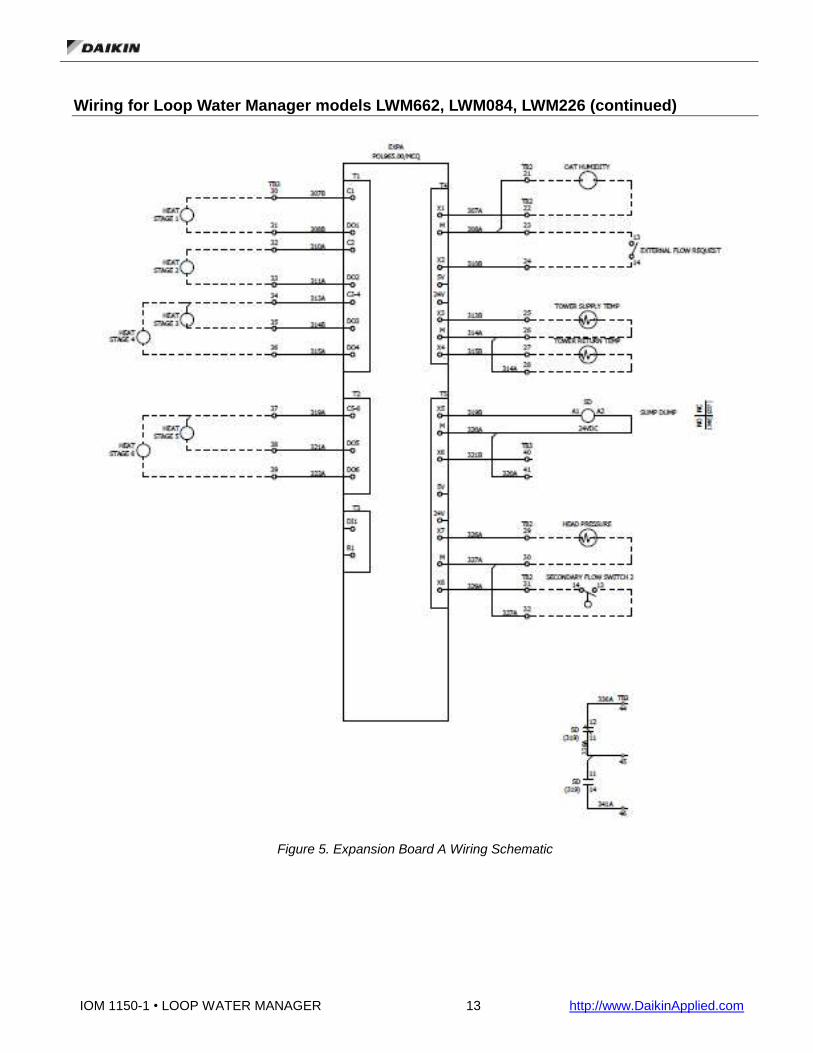
Wiring for Loop Water Manager models LWM662, LWM084, LWM226 (continued)
Figure 5. Expansion Board A Wiring Schematic

IOM 1150-1 • LOOP WATER MANAGER 14 http://www.DaikinApplied.com
Wiring for Loop Water Manager models LWM084 and LWM226 only
Figure 6. Expansion Board B Wiring Schematic

IOM 1150-1 • LOOP WATER MANAGER 15 http://www.DaikinApplied.com
Wiring for Loop Water Manager model LWM226 only
Figure 7. Expansion Board C Wiring Schematic

IOM 1150-1 • LOOP WATER MANAGER 16 http://www.DaikinApplied.com
Field Wiring
This section describes the various options and features that may require field wiring to the Loop Water Manager (LWM). The
available points depend on the model of your LWM and the configuration of your particular unit. Refer to your model number
or unit schematics to determine which points have been supplied on your unit. Which inputs and outputs you use will depend on
how you have configured the LWM. In general, terminal block TB2 contains field terminals for all inputs and TB3 contains
terminals for field connected outputs. All inputs and outputs for the LWM are designed to be dry contacts, but can be made to
be powered as indicated in the following sections.
Field Analog Output Signals
Boiler Valve
The boiler valve output is a configurable (4-20mA, 0-5VDC or 0-10VDC) output with a range that is configured within the unit
configuration menu. The X1 terminal of the main control board (TB3, terminal 20) is the signal output, with M (TB3, terminal
21) being the common for this output.
Tower Fan
The Tower Fan/Valve output is a configurable (4-20mA, 0-5VDC or 0-10VDC) output with a range that is configured within the
unit configuration menu. The X2 terminal of the main control board (TB3, terminal 22) is the signal output, with M (TB3,
terminal 23) being the common for this output.
IOM 1150-1 • LOOP WATER MANAGER 17 http://www.DaikinApplied.com
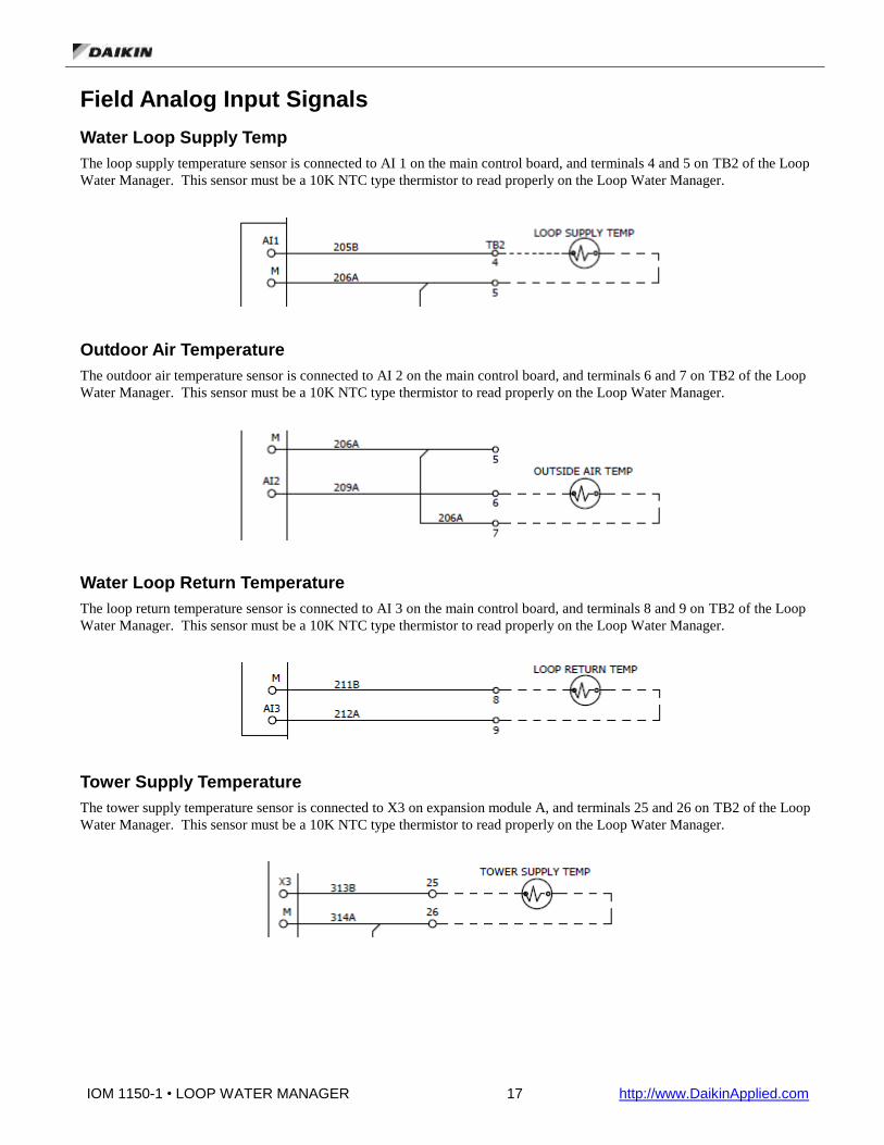
Field Analog Input Signals
Water Loop Supply Temp
The loop supply temperature sensor is connected to AI 1 on the main control board, and terminals 4 and 5 on TB2 of the Loop
Water Manager. This sensor must be a 10K NTC type thermistor to read properly on the Loop Water Manager.
Outdoor Air Temperature
The outdoor air temperature sensor is connected to AI 2 on the main control board, and terminals 6 and 7 on TB2 of the Loop
Water Manager. This sensor must be a 10K NTC type thermistor to read properly on the Loop Water Manager.
Water Loop Return Temperature
The loop return temperature sensor is connected to AI 3 on the main control board, and terminals 8 and 9 on TB2 of the Loop
Water Manager. This sensor must be a 10K NTC type thermistor to read properly on the Loop Water Manager.
Tower Supply Temperature
The tower supply temperature sensor is connected to X3 on expansion module A, and terminals 25 and 26 on TB2 of the Loop
Water Manager. This sensor must be a 10K NTC type thermistor to read properly on the Loop Water Manager.

IOM 1150-1 • LOOP WATER MANAGER 18 http://www.DaikinApplied.com
Tower Return Temperature
The tower return temperature sensor is connected to X4 on expansion module A, and terminals 27 and 28 of TB2 on the Loop
Water Manager. This sensor must be a 10K NTC type thermistor to read properly on the Loop Water Manager.
Head Pressure
The head pressure sensor is connected to X7 on expansion module A. This input is configurable (4-20mA, 0-5VDC or 0-
10VDC). The X7 terminal of the expansion module (TB2, terminal 29) is the signal input, with M (TB2, terminal 30) being the
common for this input.
Outdoor Air Humidity
The outdoor air humidity sensor is connected to X1 on expansion module A. This input is configurable (4-20mA, 0-5VDC or 0-
10VDC). The X1 terminal of the expansion module (TB2, terminal 22) is the signal input, with M (TB2, terminal 21) being the
common for this input.
Storage Tank Temperature
The storage tank temperature sensor is connected to X1 on expansion module B (if so equipped), and terminals 33 and 34 of
TB2 on the Loop Water Manager. This sensor must be a 10K NTC type thermistor to read properly on the Loop Water
Manager.
IOM 1150-1 • LOOP WATER MANAGER 19 http://www.DaikinApplied.com
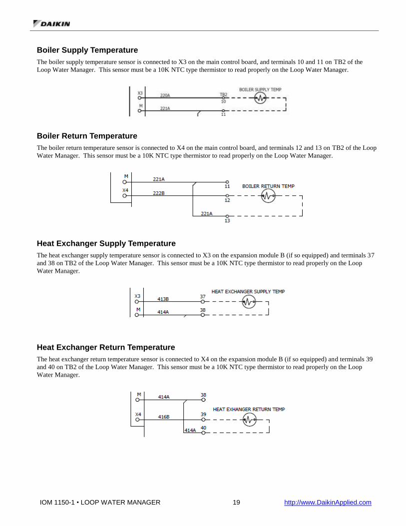
Boiler Supply Temperature
The boiler supply temperature sensor is connected to X3 on the main control board, and terminals 10 and 11 on TB2 of the
Loop Water Manager. This sensor must be a 10K NTC type thermistor to read properly on the Loop Water Manager.
Boiler Return Temperature
The boiler return temperature sensor is connected to X4 on the main control board, and terminals 12 and 13 on TB2 of the Loop
Water Manager. This sensor must be a 10K NTC type thermistor to read properly on the Loop Water Manager.
Heat Exchanger Supply Temperature
The heat exchanger supply temperature sensor is connected to X3 on the expansion module B (if so equipped) and terminals 37
and 38 on TB2 of the Loop Water Manager. This sensor must be a 10K NTC type thermistor to read properly on the Loop
Water Manager.
Heat Exchanger Return Temperature
The heat exchanger return temperature sensor is connected to X4 on the expansion module B (if so equipped) and terminals 39
and 40 on TB2 of the Loop Water Manager. This sensor must be a 10K NTC type thermistor to read properly on the Loop
Water Manager.

IOM 1150-1 • LOOP WATER MANAGER 20 http://www.DaikinApplied.com
Geothermal Temperature
The geothermal temperature sensor is connected to X5 on the expansion module B (if so equipped) and terminals 41 and 42 on
TB2 of the Loop Water Manager. This sensor must be a 10K NTC type thermistor to read properly on the Loop Water
Manager.
Field Digital Outputs Signals
Alarm LED Output
The alarm output (MCB-X5) and the alarm LED will be will be ON if there is an active alarm in the LWM and OFF if there are
no alarms. Along with the alarm LED, an audible alarm will be initiated. The audible alarm can be silenced using the alarm
silence push button on the LWM panel door.
Emergency Stop LED
The emergency stop output (MCB-X6) will be will be OFF if there is an emergency stop alarm in the LWM and ON otherwise.
The emergency stop LED will illuminate if the unit is currently in the emergency shutdown condition. Relay ES is energized by
the X6 output on the main control board and the NC contracts of that relay feed the emergency stop LED. Under normal
operating conditions, the relay is energized by the X6 output from the main control board and the NC contacts are open, de-
energizing the emergency stop LED. When an emergency stop condition occurs, the X6 output de-energizes and the NC
contacts of ES close and energize the emergency stop LED.
IOM 1150-1 • LOOP WATER MANAGER 21 http://www.DaikinApplied.com
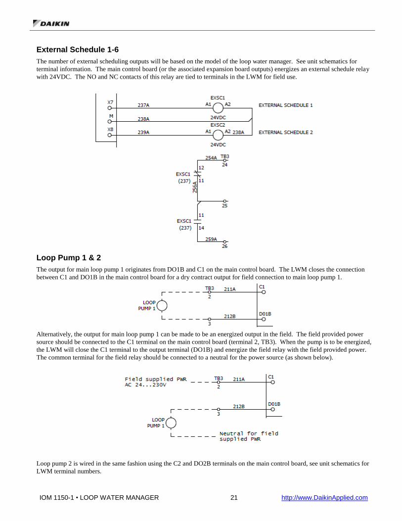
External Schedule 1-6
The number of external scheduling outputs will be based on the model of the loop water manager. See unit schematics for
terminal information. The main control board (or the associated expansion board outputs) energizes an external schedule relay
with 24VDC. The NO and NC contacts of this relay are tied to terminals in the LWM for field use.
Loop Pump 1 & 2
The output for main loop pump 1 originates from DO1B and C1 on the main control board. The LWM closes the connection
between C1 and DO1B in the main control board for a dry contract output for field connection to main loop pump 1.
Alternatively, the output for main loop pump 1 can be made to be an energized output in the field. The field provided power
source should be connected to the C1 terminal on the main control board (terminal 2, TB3). When the pump is to be energized,
the LWM will close the C1 terminal to the output terminal (DO1B) and energize the field relay with the field provided power.
The common terminal for the field relay should be connected to a neutral for the power source (as shown below).
Loop pump 2 is wired in the same fashion using the C2 and DO2B terminals on the main control board, see unit schematics for
LWM terminal numbers.

IOM 1150-1 • LOOP WATER MANAGER 22 http://www.DaikinApplied.com
Secondary Pump 1 & 2
Similar to the main loop pump outputs, the secondary pump outputs are dry connections between the C terminal and the output
terminal for the respective pump. When the pump is commanded on by the LWM, the C terminal is closed to the output
terminal internally on the main control board, creating a dry contact for the field. To create a powered output, see explanation
on “Loop Pump 1 & 2” above.
Tower Fan Enable
The Tower Fan Enable output (if applicable) can be used to provide an enable signal to the tower fan VFD. It will be energized
when the tower fan analog signal has gone above 0%. The Tower Fan Enable relay is powered from the X6 output on expansion
module B.
The NO and NC contacts of the Tower Fan Enable relay are tied to field terminals on the LWM.
IOM 1150-1 • LOOP WATER MANAGER 23 http://www.DaikinApplied.com
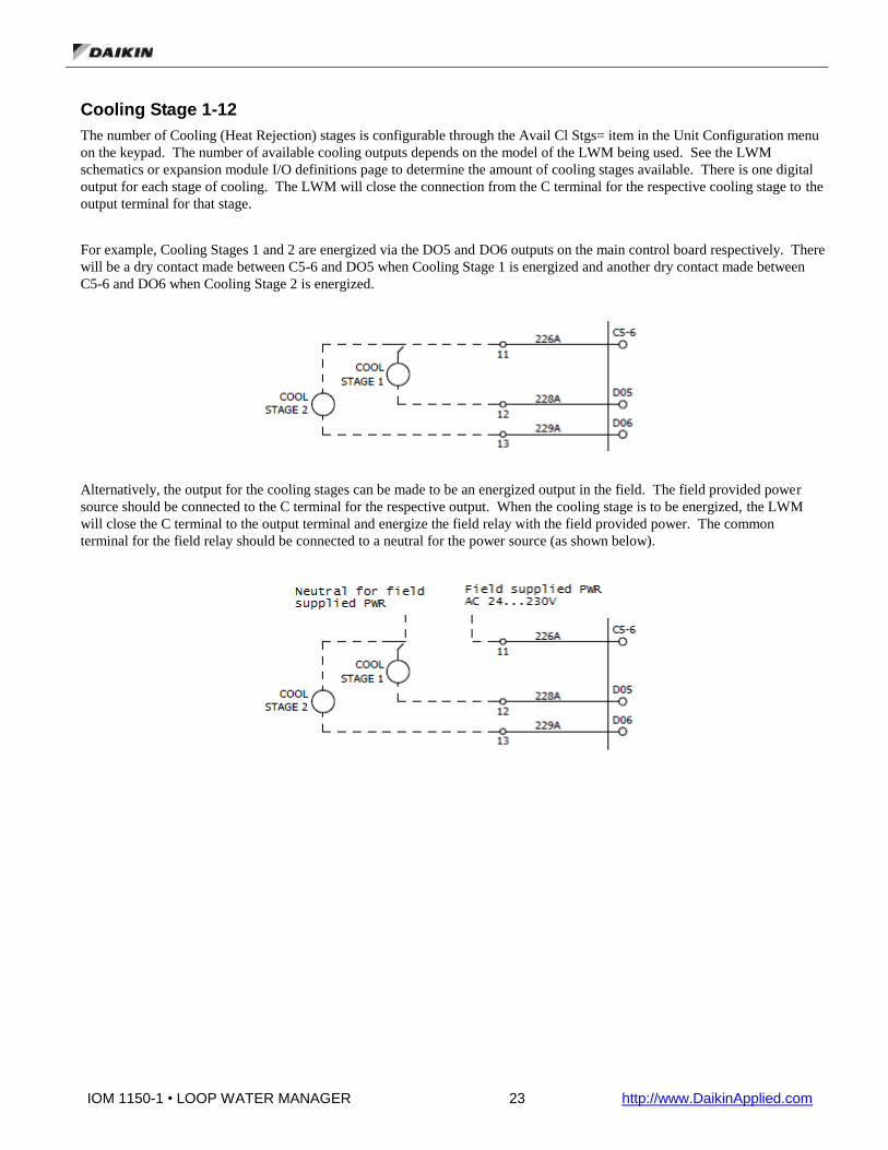
Cooling Stage 1-12
The number of Cooling (Heat Rejection) stages is configurable through the Avail Cl Stgs= item in the Unit Configuration menu
on the keypad. The number of available cooling outputs depends on the model of the LWM being used. See the LWM
schematics or expansion module I/O definitions page to determine the amount of cooling stages available. There is one digital
output for each stage of cooling. The LWM will close the connection from the C terminal for the respective cooling stage to the
output terminal for that stage.
For example, Cooling Stages 1 and 2 are energized via the DO5 and DO6 outputs on the main control board respectively. There
will be a dry contact made between C5-6 and DO5 when Cooling Stage 1 is energized and another dry contact made between
C5-6 and DO6 when Cooling Stage 2 is energized.
Alternatively, the output for the cooling stages can be made to be an energized output in the field. The field provided power
source should be connected to the C terminal for the respective output. When the cooling stage is to be energized, the LWM
will close the C terminal to the output terminal and energize the field relay with the field provided power. The common
terminal for the field relay should be connected to a neutral for the power source (as shown below).

IOM 1150-1 • LOOP WATER MANAGER 24 http://www.DaikinApplied.com
Sump Dump Output
The sump dump output energizes the SD relay with 24VDC from expansion module output X5 when a sump dump command
has been identified.
NO and NC contacts from the sump dump output are tied to field terminals to provide a dry contact for field connection. See
below.

IOM 1150-1 • LOOP WATER MANAGER 25 http://www.DaikinApplied.com
Heating Stage 1-12
The number of Heating (Heat Addition) stages is configurable through the Avail Ht Stgs= parameter on the Unit Configuration
menu on the keypad. The number of available heating outputs depends on the model of the LWM being used. See the LWM
schematics or expansion module I/O definitions page to determine the amount of heating stages available. There is one digital
output for each stage of heating. The LWM will close the connection from the C terminal for the respective heating stage to the
output terminal for that stage.
For example, heating stage 1 is energized via the DO1 output on expansion board A. There will be a dry contact made between
C1 and DO1 when heating stage 1 is energized.
Alternatively, the output for the heating stages can be made to be an energized output in the field. The field provided power
source should be connected to the C terminal for the respective output. When the heating stage is to be energized, the LWM
will close the C terminal to the output terminal and energize the field relay with the field provided power. The common
terminal for the field relay should be connected to a neutral for the power source (as shown below).
Field Digital Input Signals
Loop Flow Switch 1 & 2
The number of main loop flow switches provided is dependent on the module number of the LWM selected and number of flow
switches configured on the unit. See unit schematics or I/O definitions section to determine how many main loop flow switches
are provided with your model. The loop flow switch inputs are to be dry contacts from the field.

IOM 1150-1 • LOOP WATER MANAGER 26 http://www.DaikinApplied.com
Secondary Flow Switch 1 & 2
Similar to the main loop flow switches, the number of secondary loop flow switches provided is dependent on the module
number of the LWM selected and number of flow switches configured on the unit. See unit schematics or I/O definitions
section to determine how secondary loop flow switches are provided with your model. The secondary loop flow switch inputs
are to be dry contacts from the field.
Damper Interlock
The damper interlock input is energized with 24VAC when the field provided interlock switch makes the connection between
terminals 20A and 20B on TB2 of the LWM. When configured to use the damper interlock, the LWM is allowed to progress
from Cool Stage 1 to Cool Stage 2 when this input is made.
External Flow Request
The external flow request input is a dry contact from the field. A field-provided switch should make the connection between
terminals 23 and 24 on TB2 of the LWM for a flow request signal.
Emergency Stop Input
The emergency stop input is powered by 24VAC when a field-provided switch makes the connection between terminals 18A
and 18B on TB2 of the LWM. When this input is powered, the LWM shuts down on emergency stop alarm.

IOM 1150-1 • LOOP WATER MANAGER 27 http://www.DaikinApplied.com
Hardware
The status of all Inputs/Outputs (I/O) are available via the keypad/display.
Main Controller
Figure 8. Main Control Board
Inputs/Outputs
Table 1. Main Controller Inputs/Outputs (I/O)
Main Controller (All models)
Analog Inputs – 10K NTC
# Point Comments
AI 1 Water Loop Supply Temp 10K Thermistor
AI 2 Outside Air Temperature 10K Thermistor
AI 3 Water Loop Return Temperature 10K Thermistor
Universal Input/Output
# DI AI DO AO Point Comments
X 1
X Boiler Valve Analog Signal Configurable Analog Output
X 2
X Tower Fan/Valve Analog Signal Configurable Analog Output
X 3 X Boiler Supply Temp 10K Thermistor
X 4 X Boiler Return Temp 10K Thermistor
X 5 X Alarm LED 24 VDC
X 6 X Emergency Stop LED 24 VDC X 7 X External Schedule 1 24 VDC
X 8 X External Schedule 2 24 VDC
Digital Inputs – Dry Contacts
# Point Comments
DI 1 Loop Flow Switch 1 Flow switch for loop pump 1
DI 2 Secondary Flow Switch 1 Flow switch for the tower or boiler pump 1

IOM 1150-1 • LOOP WATER MANAGER 28 http://www.DaikinApplied.com
Digital Inputs – 24V
# Point Comments
DI 3 Emergency Stop input Shuts down LWM
DI 4 Damper Interlock Switch, when enabled, must be active before proceeding to cooling stage 2
Digital Inputs – 115V
# Point Comments
DI 5 Manual Override Panel switch for manually initiating occupied mode.
DI 6 Sump Temperature Switch Panel switch for manually initiating a sump dump.
Digital Outputs – Relay (SPST, Normally Open, 230 VAC 3 Amp)
# Point Comments
DO 1 Loop Pump 1 Activates loop pump 1
DO 2 Loop Pump 2 Activates loop pump 2
DO 3 Secondary Pump 1 Activates tower or boiler pump
pump 1 DO 4 Secondary Pump 2 Activates tower or boiler pump
pump 2 DO 5 Cooling Stage 1 Activates cooling stage 1
DO 6 Cooling Stage 2 Activates cooling stage 2
DO 7 Cooling Stage 3 Activates cooling stage 3
DO 8 Cooling Stage 4 Activates cooling stage 4
Digital Outputs – Solid State Relays, 24-230 VAC, .5A
# Point Comments
DO 9 Cooling Stage 5 Activates cooling stage 5
DO 10 Cooling Stage 6 Activates cooling stage 6
Expansion Modules
Figure 9. Expansion Modules

IOM 1150-1 • LOOP WATER MANAGER 29 http://www.DaikinApplied.com
DIP Switch Configuration
The expansion module is equipped with DIP switches for communication with the controller. Switches 1 through 5 are
configurable to set the slave address, while Switch 6 acts as peripheral bus termination. The last expansion module that is
installed must have Switch 6 set to ‘On’.
Figure 10. Expansion Module DIP Switches
The bit order for the switches is from 5 to 1. The lowest bit is 5, while the highest bit is 1. The following table shows the logic
of slave addresses:
Switch Number Value
1 24=16
2 23=8
3 22=4
4 21=2
5 20=1
Expansion Module Address Example
Let’s assume you have two expansion modules (Module A and Module B), and Module A is attached to the main unit controller
and Module B is attached to Module A. Module A is always set to address 1 and Module B is always set to address 2. In
addition, since Module B is the last module installed, switch 6 needs to be set. Therefore the DIP switches will be set as
follows:
Module A – Switch 5 is On, all others are Off Module B – Switch 4 and 6 are On, all others are Off

IOM 1150-1 • LOOP WATER MANAGER 30 http://www.DaikinApplied.com
Light Emitting Diodes (LEDs)
The expansion modules have a BSP LED and a BUS LED to indicate communication activity and status of the expansion
module. These indicators are visible when the expansion module is connected to the Unit Controller and the unit is powered on
(see Error! Reference source not found.).
BSP LED
The BSP LED indicates the state of the BSP. The table below describes the status of the BSP LED.
BSP LED Color Meaning
Alternate Red/Green Flashing BSP upgrade in progress
Green BSP is running
Red flashing with 2Hz BSP Error or slave address error1
Red Hardware Error1
1 In the event that this should occur, cycle power to the unit controller to attempt to clear the problem. Contact the Daikin
Applied Controls Customer Support Group at 866-462-7829 for additional assistance if necessary.
BUS LEDs
The BUS LED indicates the communication status between the Expansion Module and the unit controller. The table below
describes the status of the BUS LED.
BUS LED Color Meaning
Green Communication is running & I/O is working
Red Communication error
Orange / Yellow Communication is running but parameter from the application is wrong or missing, or the calibration from the factory is not correct.

IOM 1150-1 • LOOP WATER MANAGER 31 http://www.DaikinApplied.com
Expansion Module A
Inputs/Outputs
Table 2. Expansion Module A - I/O
Expansion Module A (All models)
Universal Inputs/Outputs
# DI AI DO AO Point Comments
X 1 X Outside Air Humidity Configurable Analog Input
4-20mA, 0-5VDC, or 0-10VDC
X 2 X External Flow Request Dry Contact
X 3 X Tower Supply Temperature 10K NTC Thermistor
X 4 X Tower Return Temperature 10K NTC Thermistor
X 5 X Sump Dump Output 24 VDC X 7 X Head Pressure Configurable Analog Input
4-20mA, 0-5VDC, or 0-10VDC
X 8 X Secondary Flow Switch 2 Dry contact
Digital Outputs – Relay (SPST, Normally Open, 230 VAC 3 Amp)
# Point Comments
DO 1 Heat Stage 1 Activates Heat Stage 1
DO 2 Heat Stage 2 Activates Heat Stage 2
DO 3 Heat Stage 3 Activates Heat Stage 3
DO 4 Heat Stage 4 Activates Heat Stage 4
Digital Outputs – Triac (24 VAC, .5 Amp)
# Point Comments
DO 5 Heat Stage 5 Activates Heat Stage 5
DO 6 Heat Stage 6 Activates Heat Stage 6
Note – Expansion Module A dipswitches are always set to address #1. Dipswitch #6 must be in the On position when it is the last module.
Expansion Module B
Inputs/Outputs
Table 3. Expansion Module B - I/O
Expansion Module B (Models LWM084 and LWM226 only)
Universal Inputs/Outputs
# DI AI DO AO Point Comments
X 1 X Storage Tank Temperature 10K NTC Thermistor
X 2 X Loop Flow Switch 2 Dry contact
X 3 X Heat Xchr Supply Temperature 10K NTC Thermistor
X 4 X Heat Xchr Return Temperature 10K NTC Thermistor
X 5 X Geothermal Temp 10K NTC Thermistor
X 6 X Tower Fan Enable 24 VDC
X 7 X External Schedule 3 24 VDC
X 8 X External Schedule 4 24 VDC
Digital Outputs – Relay (SPST, Normally Open, 230 VAC 3 Amp)
# Point Comments
DO 1 Cooling Stage 7 Activates cooling stage 7
DO 2 Cooling Stage 8 Activates cooling stage 8
DO 3 Cooling Stage 9 Activates cooling stage 9
DO 4 Cooling Stage 10 Activates cooling stage 10
Digital Outputs – Triac (24 VAC, .5 Amp)
# Point Comments
DO 5 Heat Stage 7 Activates heating stage 7
DO 6 Heat Stage 8 Activates heating stage 8
Note – Expansion Module B dipswitches are always set to address #2. Dipswitch #6 must be in the On position when it is the last module.

IOM 1150-1 • LOOP WATER MANAGER 32 http://www.DaikinApplied.com
Expansion Module C
Inputs/Outputs
Table 4. Expansion Module C - I/O
Expansion Module C (Model LWM226 only)
Universal Inputs/Outputs
# DI AI DO AO Point Comments
X 7 X External Schedule 5 24 VDC
X 8 X External Schedule 6 24 VDC
Digital Outputs – Relay (SPST, Normally Open, 230 VAC 3 Amp)
# Point Comments
DO 1 Heat Stage 9 Activates heating stage 9
DO 2 Heat Stage 10 Activates heating stage 10
DO 3 Cooling Stage 11 Activates cooling stage 11
DO 4 Cooling Stage 12 Activates cooling stage 12
Digital Outputs – Triac (24 VAC, .5 Amp)
# Point Comments
DO 5 Heat Stage 11 Activates heating stage 11
DO 6 Heat Stage 12 Activates heating stage 12
Note – Expansion Module C dipswitches are always set to address #3. Dipswitch #6 must be in the On position when it is the last module.

IOM 1150-1 • LOOP WATER MANAGER 33 http://www.DaikinApplied.com
Field Temperature Sensors
The Loop Water Manager requires passive negative temperature coefficient (NTC) 10K ohm sensors. These sensors vary their input resistance to the LWM as the temperature changes. Table 5 details the resistance versus temperature values. For typical sensor wiring examples, refer to the Field wiring section.
Table 5. Nominal input resistance versus temperature
Temp
(°F)
R nominal
(kΩ)
Temp
(°F)
R nominal
(kΩ)
Temp
(°F)
R nominal
(kΩ)
Temp
(°F)
R nominal
(kΩ)
Temp
(°F)
R nominal
(kΩ)
-40 336.050 -6 103.486 28 36.601 62 14.546 96 6.382
-39 323.889 -5 100.184 29 35.565 63 14.179 97 6.238
-38 312.212 -4 96.999 30 34.562 64 13.822 98 6.097
-37 300.999 -3 93.927 31 33.591 65 13.475 99 5.960
-36 290.229 -2 90.962 32 32.650 66 13.139 100 5.826
-35 279.884 -1 88.101 33 31.739 67 12.811 101 5.696
-34 269.945 0 85.340 34 30.856 68 12.493 102 5.569
-33 260.396 1 82.676 35 30.000 69 12.184 103 5.446
-32 251.218 2 80.103 36 29.171 70 11.884 104 5.325
-31 242.397 3 77.620 37 28.368 71 11.591 105 5.208
-30 233.918 4 75.222 38 27.590 72 11.307 106 5.093
-29 225.766 5 72.906 39 26.835 73 11.031 107 4.981
-28 217.928 6 70.670 40 26.104 74 10.762 108 4.872
-27 210.390 7 68.510 41 25.394 75 10.501 109 4.766
-26 203.139 8 66.424 42 24.707 76 10.247 110 4.663
-25 196.165 9 64.408 43 24.040 77 10.000 111 4.562
-24 189.455 10 62.460 44 23.394 78 9.760 112 4.463
-23 182.998 11 60.578 45 22.767 79 9.526 113 4.367
-22 176.785 12 58.759 46 22.159 80 9.298 114 4.273
-21 170.804 13 57.001 47 21.569 81 9.077 115 4.182
-20 165.048 14 55.301 48 20.997 82 8.862 116 4.093
-19 159.506 15 53.658 49 20.442 83 8.652 117 4.006
-18 154.169 16 52.069 50 19.903 84 8.448 118 3.921
-17 149.030 17 50.533 51 19.380 85 8.249 119 3.838
-16 144.081 18 49.047 52 18.873 86 8.056 120 3.757
-15 139.313 19 47.610 53 18.380 87 7.868 121 3.678
-14 134.720 20 46.220 54 17.902 88 7.685 122 3.601
-13 130.295 21 44.875 55 17.438 89 7.506 123 3.526
-12 126.031 22 43.574 56 16.988 90 7.333 124 3.453
-11 121.921 23 42.315 57 16.551 91 7.164 125 3.381
-10 117.960 24 41.097 58 16.126 92 6.999 126 3.311
-9 114.141 25 39.917 59 15.714 93 6.839 127 3.243
-8 110.460 26 38.776 60 15.313 94 6.682 128 3.176
-7 106.910 27 37.671 61 14.924 95 6.530 129 3.111

IOM 1150-1 • LOOP WATER MANAGER 34 http://www.DaikinApplied.com
Using the Keypad/Display
The keypad/display (human machine interface or HMI) on the inside of the
LWM panel consists of a 5-line by 22 character display, three keys and a
“push and roll” navigation wheel.
There is an Alarm Button, Menu (Home) Button, and a Back Button. The
wheel is used to navigate between lines on a screen (page) and to increase and
decrease changeable values when editing. Pushing the wheel acts as an Enter
Button.
The first line on each page includes the page title and the line number to which
the cursor is currently “pointing”. The line numbers are X/Y to indicate line
number X of a total of Y lines for that page. The left most position of the title
line includes an “up” arrow to indicate there are pages “above” the currently
displayed items, a “down” arrow to indicate there are pages “below” the
currently displayed items or an “up/down” arrow to indicate there are pages
“above and below” the currently displayed page.
Each line on a page can contain status only information or include changeable data fields. When a line contains status only
information and the cursor is on that line all but the value field of that line is highlighted meaning the text is white with a black
box around it. When the line contains a changeable value and the cursor is at that line, the entire line is highlighted. Each line
on a page may also be defined as a “jump” line, meaning pushing the navigation wheel will cause a “jump” to a new page. An
arrow is displayed to the far right of the line to indicate it is a “jump” line and the entire line is highlighted when the cursor is on
that line.
Passwords
The three password levels available are Level 2, Level 4, and Level 6, with Level 2 having the highest level of access. Entering
the Level 6 password (or no password) allows access to the Quick Menu, Alarm Lists, and About this LWM menus. Entering
the Level 2 or 4 passwords allows similar access to Level 6 with the addition of the I/O Setup menus. The Level 2 password is
6363, the Level 4 is 2526 and the Level 6 password is 5321.
Continuing without entering one of these three levels allows access only to the I/O Status menus.

IOM 1150-1 • LOOP WATER MANAGER 35 http://www.DaikinApplied.com
The password field initially has a value **** where each * represents an adjustable field. These values can be changed by
entering the Edit Mode described below.
1/1Enter Password
Enter Password ****
Entering an invalid password has the same effect as continuing without entering a password.
Once a valid password has been entered, the controller allows further changes and access without requiring the user to enter a
password until either the password timer expires or a different password is entered. The default value for this password timer is
10 minutes.
The password setup is shown above.
Navigation Mode
In the Navigation Mode, when a line on a page contains no editable fields, all but the value field of that line is highlighted
meaning the text is white with a black box around it. When the line contains an editable value field, the entire line is inverted
when the cursor is pointing to that line.
When the navigation wheel is turned clockwise, the cursor moves to the next line (down) on the page. When the wheel is turned
counter-clockwise the cursor moves to the previous line (up) on the page. The faster the wheel is turned the faster the cursor
moves.
When the Back Button is pressed the display reverts back to the previously displayed page. If the Back button is repeatedly
pressed the display continues to revert one page back along the current navigation path until the “main menu” is reached.
When the Menu (Home) Button is pressed the display reverts to the “main page”.
When the Alarm Button is depressed, the Alarm Lists menu is displayed. Since alarms are not implemented in this version,
there will never be alarms listed here.
Edit Mode
The Editing Mode is entered by pressing the navigation wheel while the cursor is pointing to a line containing an editable field.
Once in the edit mode pressing the wheel again causes the editable field to be highlighted. Turning the wheel clockwise while
the editable field is highlighted causes the value to be increased. Turning the wheel counter-clockwise while the editable field is
highlighted causes the value to be decreased. The faster the wheel is turned the faster the value is increased or decreased.
Pressing the wheel again causes the new value to be saved and the keypad/display to leave the edit mode and return to the
navigation mode.
Unit Support
From the Main Screen\Commission Unit menu, the user can change the type of units that are displayed on the keypad/display.
The options include English (default) or SI. Power must be cycled to the unit controller before changes to Unit Support take
effect.
Access to the Commission Unit menu requires a level 2 or level 4 password.

IOM 1150-1 • LOOP WATER MANAGER 36 http://www.DaikinApplied.com
Software Startup Process
Prior to the LWM power-up, all auxiliary control devices such as pumps, cooling tower, boilers, and valves should be checked,
tested, and started in accordance with the manufacturer’s instructions. Also, ensure that all components are connected,
particularly the Loop Supply Temperature sensor. If some sensors are enabled and not connected, alarms will be generated.
After power-up, the unit will start up in Off mode (Control Mode=Off), with no outputs energized. The user should then take
the following steps:
1. Log in to the keypad/display.
2. Go to the Unit Configuration/Component Setup menu and ensure that all available settings are properly configured for
the system. If any changes are made, the Apply Changes line must be set to ‘Yes’. This will cycle power to the
controller.
3. Navigate to the critical settings menus - Unit Configuration/Safety Setpoints, Unit Configuration/Clock Setup – to
ensure critical system functions run unhindered. These changes do not require a system restart to apply.
4. Navigate to the Unit Control submenus to configure system operations to the user’s preference.
5. Navigate to the schedules and setup schedules as needed.
6. When the unit is properly configured, set Control Mode, on the main menu, appropriately.
Unit Configuration
The following configuration options are all found within the Main Menu/Unit Configuration menu of the keypad/display.
Access to this menu requires a Level 2 password access or higher. Following any changes to the members of this menu, the
Apply Changes option must be activated, or the system will not recognize them.
Radiant Loop App
This setting should be set to ‘Yes’, if the LWM is used as a radiant loop application. When set to true, no cooling can be
configured. Default = No.
Main Loop Pumps
This setting defines to the controller the number of pumps installed to generate flow in the main water loop. Default = 2.
Secondary Loop Pumps
This setting defines to the controller the number of secondary pumps installed. Default = 2.
Main Loop Flow Switches
This setting informs the controller of how many flow switches to expect in the main water loop. The number of main loop flow
switches available will depend on the model of LWM you have, see I/O portion of the main controller section for point
availability by model number. It is assumed that a setting of 1 means that the one flow switch is installed in such a way that it
will detect flow regardless of which pump is creating it, should there be 2 pumps installed. Likewise, it is assumed that a setting
of 2 means that two flow switches are installed to generate unique presence-of-flow signals from the two installed pumps. A
setting of 2 combined with a setting of 1 in the main loop pumps line is considered invalid, and will be reset to 1 automatically.
Default = 1.
Secondary Loop Flow Switches
This setting informs the controller of how many secondary loop flow switches are installed. It operates under the same
assumptions as the main flow loop switch settings, as pertains to the secondary water loop. Default = 1.
Secondary Loop Pump 1 & 2 Function
This setting determines under what circumstances the secondary loop pump is allowed to function. There can be a total of two
secondary pumps and each one can be configured independently as a boiler loop pump or a tower loop pump. If the unit is
configured for two secondary pumps and they are of the same type (boiler or tower), then an additional lead/lag feature can be
used in which you select which pump should attempt to run first or start the one with the least number of run hours (auto
lead/lag). Both pumps will never run at the same time. If the pumps are of different types, lead/lag does not apply. Default =
None.

IOM 1150-1 • LOOP WATER MANAGER 37 http://www.DaikinApplied.com
Available Heat Stages
This setting specifies how many heat addition stages are available to the controller for use during normal occupied operation.
Higher values of this setting may require additional I/O expansion modules for proper functionality. The number of heating
stages available will depend on the model of LWM you have, see I/O portion of the main controller section for point availability
by model number. Default = None.
Available Cool Stages
This setting specifies how many heat rejection stages are available to the controller for use during normal occupied operation.
Higher values of this setting may require additional I/O expansion modules for proper functionality. The number of cooling
stages available will depend on the model of LWM you have, see I/O portion of the main controller section for point availability
by model number. Default = None.
PreHeat/PreCool Enable
These settings enable PreHeat or PreCool operation, and are not mutually exclusive. The function of these operational settings
is described in the previous section “System Features”. Enabling of these features activates the Unit Control/PreHeat & PreCool
menu option. Default = Off.
Boiler Valve Active
This setting allows the user to configure the presence of a boiler valve for heat addition control. Default = None.
Boiler Output Type
This setting allows the user to configure the type of output used to for the Boiler Output. Default = 0-10VDC.
Tower Fan Active
This setting allows the user to configure the presence of a tower fan or control valve for heat rejection control. Default = None.
Tower Output Type
This setting allows the user to configure the type of output used to for the Tower Output. Default = 0-10VDC.
Loop Return Sensor
This setting allows the user to configure the whether or not there is a loop return sensor present. Default = Disable.
Head Pressure Sensor
The three settings involving the head pressure sensor allow the user to configure the different properties of the sensor. The
sensor may be configured as a 5VDC, 10VDC, or 4-20mA sensor, with the ability to set the sensory range. Default = Disabled,
None, 500.0psi
Head Pressure Sensor Type
This setting allows the user to configure the type of head pressure sensor. Default = None.
Pressure Sensor Range
Default = 500.0psi.
Outside Air Humidity Sensor Enable
This setting allows the user to enable an outside air humidity sensor. Default = None.
Outside Air Humidity Sensor
This setting allows the user to configure the type of sensor used for the outside air humidity sensor. The sensor may be
configured in 5VDC, 10VDC or 4-20mA setups. Default = None.
Sensor Enables
The list of sensor enables (Loop Return Temp, Boiler Supply Temp, Tower Return Temp, etc.) is a series of optional, display-
only temperature sensors. They are expected to be temperature probe sensors utilizing the same temperature/resistance table
used by the main Loop Supply Temperature sensor. When enabled, they will be displayed on the Unit Status screen. Default =
Disabled.

IOM 1150-1 • LOOP WATER MANAGER 38 http://www.DaikinApplied.com
Damper Interlock
This setting enables a digital input designated for interlock circuitry during heat rejection staging. When active, the controller
will wait for this input to be active before progressing to Cool Stage 2. When disabled, the controller will not pause between
Cool Stages 1 and 2 for any length of time more than the stage timer requires.
External Schedules
This setting allows the user to specify a number of digital outputs to use for external occupancy indication. The number of
scheduling outputs available will depend on the model of LWM you have, see I/O portion of the main controller section for
point availability by model number. Default = 1.
Staged Heating Outdoor Air Reset
This setting enables the outdoor air reset of the staged heating (heat addition) setpoints. This feature is described in the Error!
Reference source not found. section. Also enabled is the menu containing settings for this feature, held at View/Set Unit\Stg
OA Reset. Default = None.
Boiler Valve Outdoor Air Reset
This setting enables the outdoor air reset of the boiler valve setpoint. This featureis described in the Error! Reference source
not found. section. Also enabled is the menu containing settings for this feature, held at View/Set Unit\Stg OA Reset. Default
= None.

IOM 1150-1 • LOOP WATER MANAGER 39 http://www.DaikinApplied.com
Keypad/Display Menu Structure
Figure 11 through
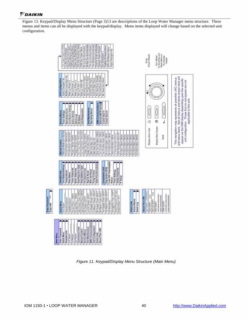
IOM 1150-1 • LOOP WATER MANAGER 40 http://www.DaikinApplied.com
Figure 13. Keypad/Display Menu Structure (Page 3)13 are descriptions of the Loop Water Manager menu structure. These
menus and items can all be displayed with the keypad/display. Menu items displayed will change based on the selected unit
configuration.
Figure 11. Keypad/Display Menu Structure (Main Menu)
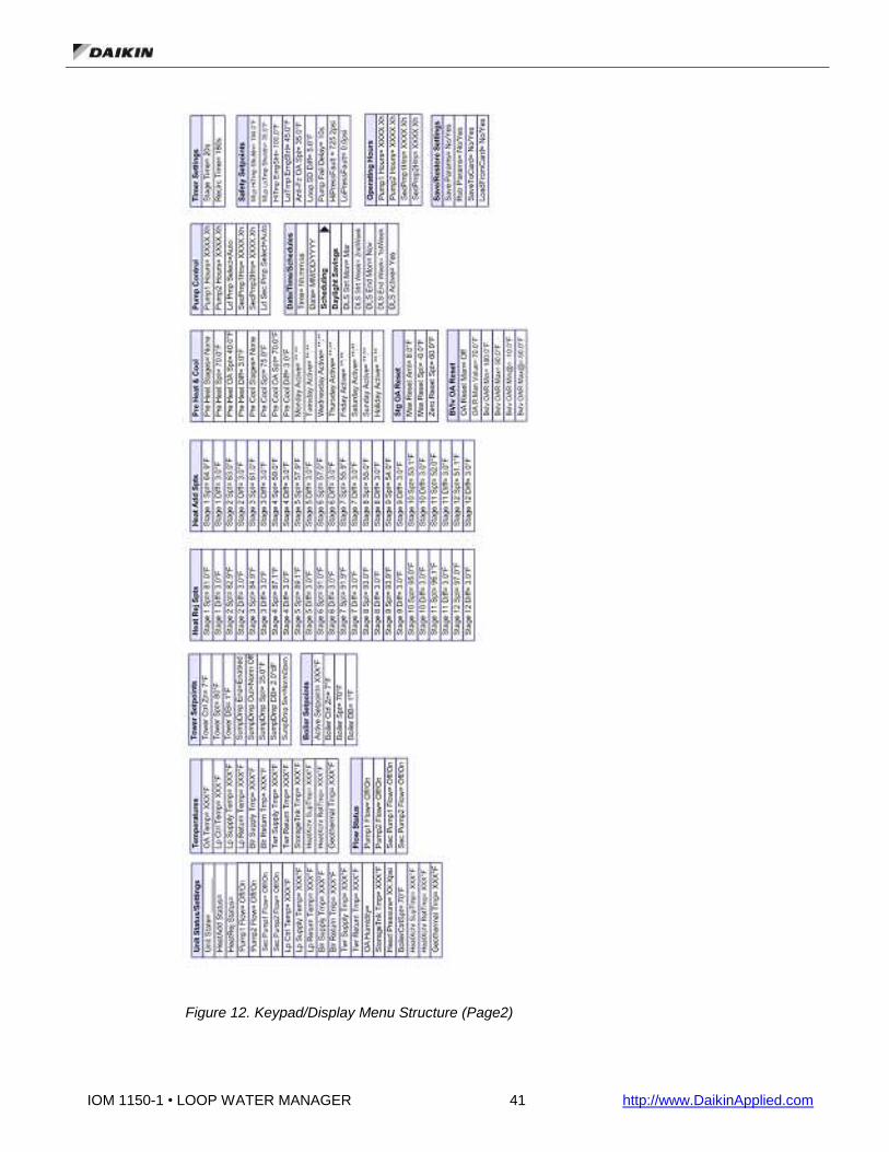
IOM 1150-1 • LOOP WATER MANAGER 41 http://www.DaikinApplied.com
Figure 12. Keypad/Display Menu Structure (Page2)

IOM 1150-1 • LOOP WATER MANAGER 42 http://www.DaikinApplied.com
Figure 13. Keypad/Display Menu Structure (Page 3)
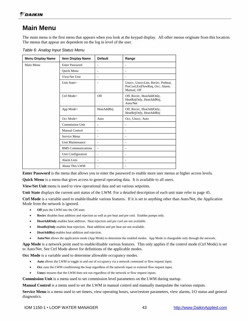
IOM 1150-1 • LOOP WATER MANAGER 43 http://www.DaikinApplied.com
Main Menu
The main menu is the first menu that appears when you look at the keypad display. All other menus originate from this location.
The menus that appear are dependent on the log in level of the user.
Table 6: Analog Input Status Menu
Menu Display Name Item Display Name Default Range
Main Menu Enter Password - -
Quick Menu - -
View/Set Unit - -
Unit State= - Unocc, UnoccLim, Recirc, Preheat, PreCool,ExtFlowReq, Occ, Alarm, Manual, Off
Ctrl Mode= Off Off, Recirc, HeatAddOnly, HeatRejOnly, HeatAddRej, Auto/Net
App Mode= HeatAddRej Off, Recirc, HeatAddOnly, HeatRejOnly, HeatAddRej
Occ Mode= Auto Occ, Unocc, Auto
Commission Unit - -
Manual Control - -
Service Menu - -
Unit Maintenance - -
BMS Communications - -
Unit Configuration - -
Alarm Lists - -
About This LWM - -
Enter Password is the menu that allows you to enter the password to enable more user menus at higher access levels.
Quick Menu is a menu that gives access to general operating data. It is available to all users.
View/Set Unit menu is used to view operational data and set various setpoints.
Unit State displays the current unit status of the LWM. For a detailed description of each unit state refer to page 45.
Ctrl Mode is a variable used to enable/disable various features. If it is set to anything other than Auto/Net, the Application
Mode from the network is ignored.
Off puts the LWM into the Off state.
Recirc disables heat addition and rejection as well as pre heat and pre cool. Enables pumps only.
HeatAddOnly enables heat addition. Heat rejection and pre cool are not available.
HeatRejOnly enables heat rejection. Heat addition and pre heat are not available.
HeatAddRej enables heat addition and rejection.
Auto/Net allows the application mode (App Mode) to determine the enabled modes. App Mode is changeable only through the network.
App Mode is a network point used to enable/disable various features. This only applies if the control mode (Ctrl Mode) is set
to Auto/Net. See Ctrl Mode above for definitions of the applicable modes.
Occ Mode is a variable used to determine allowable occupancy modes.
Auto allows the LWM to toggle in and out of occupancy via a network command or flow request input.
Occ runs the LWM conditioning the loop regardless of the network input or external flow request input.
Unocc ensures that the LWM does not run regardless of the network or flow request inputs.
Commission Unit is a menu used to set commission level parameters on the LWM during startup.
Manual Control is a menu used to set the LWM in manual control and manually manipulate the various outputs.
Service Menu is a menu used to set timers, view operating hours, save/restore parameters, view alarms, I/O status and general
diagnostics.

IOM 1150-1 • LOOP WATER MANAGER 44 http://www.DaikinApplied.com
Unit Maintenance is a menu used to view operating hours.
BMS Communications is a menu used to configure the network communication module.
Unit Configuration is a menu used to configure the LWM. Apply Changes must be set to ‘Yes’ after making any changes to
this menu. This will cycle power to the LWM unit controller.
Alarm Lists is a menu used to view active alarms, the alarm log and to clear the active alarms or alarm log.
About This LWM is a menu used to view information about the LWM including software and BSP versions.
Quick Menu
Items in the Quick Menu contain basic unit operating status and control set point parameters. The items shown in the Quick
Menu are Read Only if a valid password has not been entered. The following are brief descriptions of the Quick Menu items.
No password is required to view the Quick Menu.
Table 7: Quick Menu
Menu Display Name Item Display Name Default Range
Quick Menu Unit State= - Unocc, UnoccLim, Recirc, Preheat, PreCool,ExtFlowReq, Occ, Alarm, Manual, Off
Occ Mode= Auto Occ, Unocc, Auto
HeatAdd Status= - None, OffLoc, OffNet, Enabled, Alarm
HeatRej Status= - None, OffLoc, OffNet, Enabled, Alarm
Pump1 Flow= - Off/On
Pump2 Flow= - Off/On
Sec Pump1 Flow= - Off/On
Sec Pump2 Flow= - Off/On
OA Temp= - -
Lp Ctrl Temp - -
Lp Supply Temp= - -
LpReturn Temp= - -
Blr Supply Tmp= - -
Blr Return Tmp= - -
Twr Supply Temp= - -
Twr Return Tmp= - -
OA Humidity= - -
StorageTnk Tmp= - -
Head Pressure= - -
BoilerCtrlSpt= - -
Unit State is the current unit state of the LWM. For a detailed description of each unit state refer to page 45.
Occ Mode is a variable used to determine allowable occupancy modes.
Auto allows the LWM to toggle in and out of occupancy via a network command or flow request input.
Occ runs the LWM conditioning the loop regardless of the network input or external flow request input.
Unocc ensures that the LWM does not run regardless of the network or flow request inputs.
HeatAdd Status defines the current status of heat addition. None – LWM is configured for 0 stages of heat addition and no boiler valve
OffLoc – The control mode is locking out heat addition.
OffNet – The network is locking out heat addition through the Application Mode.
Enabled – Heat addition is enabled and available if required. It does not mean it is currently running.
Alarm – All secondary pumps are off on alarm (ie, Secondary Loop Pump Fail Problem is active).

IOM 1150-1 • LOOP WATER MANAGER 45 http://www.DaikinApplied.com
HeatRej Status, defines the current status of heat rejection. None – LWM is configured for 0 stages of heat rejection and no tower valve
OffLoc – The control mode is locking out heat rejection.
OffNet – The network is locking out heat rejection through the Application Mode.
Enabled – Heat rejection is enabled and available if required. It does not mean it is currently running.
Alarm – All secondary pumps are off on alarm (i.e., Secondary Loop Pump Fail Problem is active).
Pump1 Flow is the current status of the Pump 1 Flow digital input.
Pump2 Flow is the current status of the Pump 2 Flow digital input.
Sec Pump1 Flow is the current status of the Secondary Pump 1 Flow digital input.
Sec Pump2 Flow is the current status of the Secondary Pump 2 Flow digital input.
OA Temp is the outdoor air temperature.
Lp Ctrl Temp is the loop control temperature. It is either supply or return depending on the configuration.
Lp Supply Temp is the current loop supply temperature.
Lp Return Temp is the current loop return temperature.
Blr Supply Temp is the current boiler supply temperature.
Blr Return Temp is the current boiler return temperature.
Twr Supply Temp is the current tower supply temperature.
Twr Return Temp is the current tower return temperature.
OA Humidity is the current outdoor air humidity.
StorageTnk Tmp is the current storage tank temperature.
Head Pressure is the current Head Pressure.
BoilerCtrlSpt is the current setpoint being used for boiler control.
Table 8: View/Set Unit Menu
Menu Display Name Item Display Name Default Range
View/Set Unit Unit Status/Settings - -
Temperatures - -
Flow Status - -
Tower Setpoints - -
Boiler Setpoints - -
Heat Rejection Spts - -
Heat Addition Spts - -
Pre Heat & Cool - -
Stg OA Reset - -
BVlv OA Reset - -
Pump Control - -
Date/Time/Schedules - -

IOM 1150-1 • LOOP WATER MANAGER 46 http://www.DaikinApplied.com
Unit Status/Settings Menu
The “Unit Status/Settings” menu provides a summary of basic unit status and control items. This menu summarizes the current
operating state of the unit, giving the operating state the unit is in, along with the current capacity level of that operating state.
Table 9. Unit Status/Settings Menu
Menu Display Name Item Display Name Default Range
Unit Status/Settings Unit State= - Unocc, UnoccLim, Recirc, Preheat, PreCool,ExtFlowReq, Occ, Alarm, Manual, Off
Occ Mode= Auto Occ, Unocc, Auto
HeatAdd Status= - None, OffLoc, OffNet, Enabled
HeatRej Status= - None, OffLoc, OffNet, Enabled
Pump1 Flow= - Off/On
Pump2 Flow= - Off/On
Sec Pump1 Flow= - Off/On
Sec Pump2 Flow= - Off/On
Local OAT= - -
Lp Ctrl Temp= - -
Lp Supply Temp= - -
LpReturn Temp= - -
Blr Supply Tmp= - -
Blr Return Tmp= - -
Twr Supply Temp= - -
Twr Return Tmp= - -
OA Humidity= - -
StorageTnk Tmp= - -
Head Pressure= - -
BoilerCtrlSpt= - -
HeatXchr SupTmp= - -
HeatXchr RetTmp=
Geothermal Tmp=
Unit State is the current unit state of the LWM.
Unocc (Unoccupied) is the resting/standby state for the controller. All systems are within acceptable parameters
and there are no requests for flow, either scheduled or manual. No outputs, digital or analog, are active. The
system is monitoring outdoor air temperature and the loop water temperature for a breach of acceptable
boundaries, but is otherwise at rest.
UnoccLim (Unoccupied Limit Protect) is not a scheduled or requested response, but the system has detected that
the loop water temperature has broken the acceptable threshold or the outdoor air temperature presents a risk of the
loop water freezing, and therefore must activate in order to prevent damage to the system. The system will turn on
and behave as if it were in Occupied mode. If the setpoints are aligned as intended, the system will advance
through its stages until all available heat addition stages are active, although this may not necessarily be the case.
The system will remain active and heating until such time as the outdoor air temperature increases above the
setpoint, the loop water temperature increases above the setpoint + differential, or a scheduled or manual event
occurs.
Recirc (Recirculate) is used to activate the lead main and secondary pumps, beginning head pressure control, if
available. Temperature control is inactive. The system should not attempt temperature control until the system’s
loop water is flowing and not stagnant. All outputs not related to external scheduling or flow control shall be
inactive. This state shall be maintained for a user specified amount of time before proceeding to any temperature
controlling state.
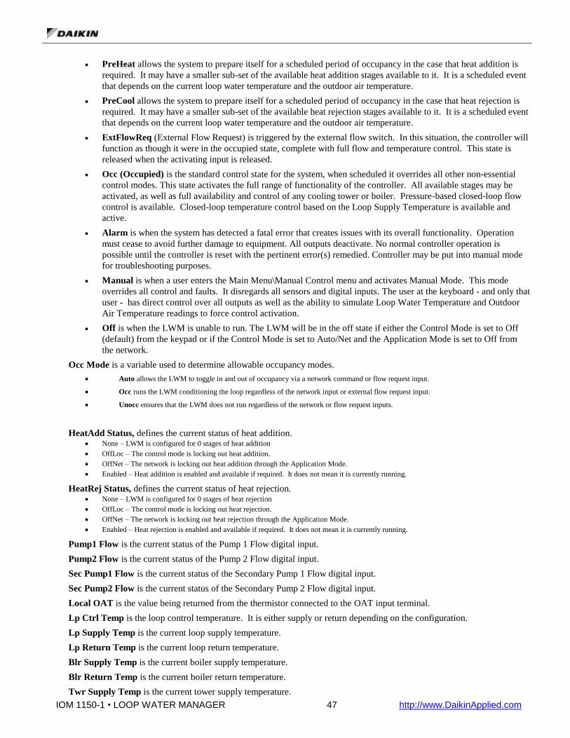
IOM 1150-1 • LOOP WATER MANAGER 47 http://www.DaikinApplied.com
PreHeat allows the system to prepare itself for a scheduled period of occupancy in the case that heat addition is
required. It may have a smaller sub-set of the available heat addition stages available to it. It is a scheduled event
that depends on the current loop water temperature and the outdoor air temperature.
PreCool allows the system to prepare itself for a scheduled period of occupancy in the case that heat rejection is
required. It may have a smaller sub-set of the available heat rejection stages available to it. It is a scheduled event
that depends on the current loop water temperature and the outdoor air temperature.
ExtFlowReq (External Flow Request) is triggered by the external flow switch. In this situation, the controller will
function as though it were in the occupied state, complete with full flow and temperature control. This state is
released when the activating input is released.
Occ (Occupied) is the standard control state for the system, when scheduled it overrides all other non-essential
control modes. This state activates the full range of functionality of the controller. All available stages may be
activated, as well as full availability and control of any cooling tower or boiler. Pressure-based closed-loop flow
control is available. Closed-loop temperature control based on the Loop Supply Temperature is available and
active.
Alarm is when the system has detected a fatal error that creates issues with its overall functionality. Operation
must cease to avoid further damage to equipment. All outputs deactivate. No normal controller operation is
possible until the controller is reset with the pertinent error(s) remedied. Controller may be put into manual mode
for troubleshooting purposes.
Manual is when a user enters the Main Menu\Manual Control menu and activates Manual Mode. This mode
overrides all control and faults. It disregards all sensors and digital inputs. The user at the keyboard - and only that
user - has direct control over all outputs as well as the ability to simulate Loop Water Temperature and Outdoor
Air Temperature readings to force control activation.
Off is when the LWM is unable to run. The LWM will be in the off state if either the Control Mode is set to Off
(default) from the keypad or if the Control Mode is set to Auto/Net and the Application Mode is set to Off from
the network.
Occ Mode is a variable used to determine allowable occupancy modes.
Auto allows the LWM to toggle in and out of occupancy via a network command or flow request input.
Occ runs the LWM conditioning the loop regardless of the network input or external flow request input.
Unocc ensures that the LWM does not run regardless of the network or flow request inputs.
HeatAdd Status, defines the current status of heat addition. None – LWM is configured for 0 stages of heat addition
OffLoc – The control mode is locking out heat addition.
OffNet – The network is locking out heat addition through the Application Mode.
Enabled – Heat addition is enabled and available if required. It does not mean it is currently running.
HeatRej Status, defines the current status of heat rejection. None – LWM is configured for 0 stages of heat rejection
OffLoc – The control mode is locking out heat rejection.
OffNet – The network is locking out heat rejection through the Application Mode.
Enabled – Heat rejection is enabled and available if required. It does not mean it is currently running.
Pump1 Flow is the current status of the Pump 1 Flow digital input.
Pump2 Flow is the current status of the Pump 2 Flow digital input.
Sec Pump1 Flow is the current status of the Secondary Pump 1 Flow digital input.
Sec Pump2 Flow is the current status of the Secondary Pump 2 Flow digital input.
Local OAT is the value being returned from the thermistor connected to the OAT input terminal.
Lp Ctrl Temp is the loop control temperature. It is either supply or return depending on the configuration.
Lp Supply Temp is the current loop supply temperature.
Lp Return Temp is the current loop return temperature.
Blr Supply Temp is the current boiler supply temperature.
Blr Return Temp is the current boiler return temperature.
Twr Supply Temp is the current tower supply temperature.

IOM 1150-1 • LOOP WATER MANAGER 48 http://www.DaikinApplied.com
Twr Return Temp is the current tower return temperature.
OA Humidity is the current outdoor air humidity.
StorageTnk Tmp is the current storage tank temperature.
Head Pressure is the current Head Pressure.
BoilerCtrlSpt is the current setpoint being used for boiler control.
HeatXchr SupTmp is the current heat exchanger supply temperature. It is for display only. There is no control associated
with this temperature.
HeatXchr RetTmp is the current heat exchanger return temperature. It is for display only. There is no control associated
with this temperature.
Geothermal Tmp is the current geothermal temperature. It is for display only. There is no control associated with this
temperature.
Temperatures Menu
The Temperatures menu contains the status of various temperatures in the LWM.
Table 10. Temperatures Menu
Menu Display Name Item Display Name Default Range
Temperatures OA Temp= - -
Lp Ctrl Temp= - -
Lp Supply Temp= - -
Lp Return Temp= - -
Blr Supply Tmp= - -
Blr Return Temp= - -
Twr Supply Tmp= - -
Twr Return Temp= - -
StorageTnk Tmp= - -
HeatXchr SupTmp= - -
HeatXchr RetTmp=
Geothermal Tmp=
OA Temp is the current outdoor air temperature. When the network is not writing to the OAT network variable, this value
will indicate the current status of the OAT input terminal. When the network is writing to the OAT network variable, this
value will indicate the network value.
Lp Ctrl Temp is the current loop control temperature (space or return).
Lp Supply Temp is the current loop supply temperature.
Lp Return Temp is the current loop return temperature.
Blr Supply Temp is the current boiler supply temperature.
Blr Return Temp is the current boiler return temperature.
Twr Supply Temp is the current tower supply temperature.
Twr Return Temp is the current tower return temperature.
StorageTnk Tmp is the current storage tank temperature.
HeatXchr SupTmp is the current heat exchanger supply temperature. It is for display only. There is no control associated
with this temperature.
HeatXchr RetTmp is the current heat exchanger return temperature. It is for display only. There is no control associated
with this temperature.
Geothermal Tmp is the current geothermal temperature. It is for display only. There is no control associated with this
temperature.

IOM 1150-1 • LOOP WATER MANAGER 49 http://www.DaikinApplied.com
Main Loop Flow Control
The Loop Water Manager is able to maintain control of and verify the water flow within the main water loop of the system. It
provides up to two digital outputs to start a field provided and wired main loop pump. An input from a field mounted flow
switch is monitored to determine if the pump achieves flow. If the main pump is activated, but does not achieve enough flow to
make the flow switch, a pump alarm is initiated and the pump output is deactivated. If the Loop Water Manager is configured
for a second main pump, it will attempt to start the second pump to achieve flow in the loop. In this dual main pump
configuration, the user may select which pump shall be the lead pump or select “auto”, in which the controller will automatically
select the pump with the least amount of run hours. If the second pump fails to achieve flow, it will also be shut down and the
Loop Water Manager will stay off in alarm, until the error(s) have been remedied and the alarms manually cleared at the LWM.
Additionally, the LWM can be configured to control up to two secondary pumps for a tower or boiler loop.
Flow Status Menu
The Flow Status Menu contains the flow status for primary and secondary pumps.
Table 11. Flow Status Menu
Menu Display Name Item Display Name Default Range
Flow Status Pump1 Flow= - Off, On
Pump2 Flow= - Off, On
Sec Pump1 Flow= - Off, On
Sec Pump2 Flow= - Off, On
Pump1 Flow tells if the pump1 switch is indicating flow (On) or not (Off).
Pump2 Flow tells if the pump2 switch is indicating flow (On) or not (Off).
Sec Pump1 Flow tells if the secondary pump1 switch is indicating flow (On) or not (Off).
Sec Pump2 Flow tells if the secondary pump2 switch is indicating flow (On) or not (Off).
Optional Tower or Boiler Valve Control
The LWM is capable of analog valve position control for heating or cooling of the main loop. The control loop is temperature-
based, with the loop control temperature (supply or return) as the measured variable.
The LWM’s analog position control is an analog signal. Any valve or fan that may be connected to that output must either be
compatible with that specified signal range or create peripheral circuitry to compensate.
Tower and boiler valve control setpoints are independent of the staged heat addition/rejection setpoints, but are only enabled
when one stage is active.
Tower Setpoint Menu
The Loop Water Manager can control an optional cooling tower fan speed or valve. The output is controlled via an analog
signal. The tower fan/valve has its own setpoint, deadband, and control zone configuration points. These configuration points
dictate the behavior and temperature control based around the tower. The cooling tower waits for the activation of Cool Stage 1
before allowing its fan to activate. The tower and cool staging process are otherwise independent outside of the fact that both
control the same medium based on the same measured value.

IOM 1150-1 • LOOP WATER MANAGER 50 http://www.DaikinApplied.com
Tower Sump Dump Control
The Loop Water Manager is equipped to control a tower sump. The tower sump can be dumped via a two position switch on
the outside of the panel or trigger automatically on an outdoor air temperature setpoint. The sump may also be configured to
dump or fill based on a schedule set on the LWM.
There are two options available to control how to dump the sump. The parameters to setup this control are located on the Tower
Setpoints menu on the HMI.
Options one and two include the use of Sump Dump Select. Using this variable, you can dump the sump based on a hardware
switch (MCB-DI6) and based on Outdoor Air Temperature (OAT). The switch can be configured to be normally open or
normally closed using the “SumpDmp Sw” item on the HMI. If normally open is selected, the sump will dump when the switch
is closed. If normally closed is selected, the sump will dump when the switch is open. If this feature is enabled by setting Sump
Dump Select to Enable, the sump will dump when either the switch tells it to, or the OAT drops below the sump dump setpoint
minus the sump dump deadband. It will refill when both the switch indicates fill and OAT rises above the sump dump setpoint
plus the sump dump deadband. Selecting Disable for Sump Dump Select, disables the ability to dump the sump based on switch
and OAT.
The second option to dump the sump is to setup a dump month and day along with a corresponding sump fill month and day. If
the current date in the controller is between the dump and fill dates, the sump will be dumped. Otherwise, it will be filled. This
option can be used at the same time as Sump Dump Select is used. If either option call for the sump to dump, the sump will
dump.
The output used to dump or fill the sump (EMA-X5) is also fully configurable using the SumpDmp Out item on the HMI. If this
parameter is set to Norm Off, then the output will be On to dump the sump. If this parameter is set to Norm On, the output will
be Off to dump the sump.
The Tower Setpoint Menu contains setpoints used to for tower control.
Table 12. Tower Setpoints Menu
Menu Display Name Item Display Name Default Range
Tower Setpoints Tower Ctrl Zone= 7°F 1-20°F
Tower Spt= 80°F 0-200°F – Can’t overlap heat addition or boiler setpoints, if they are present.
Tower DB= 1°F 0-10°F
SumpDmp Ena= Enable Disable, Enable
SumpDmp Out= Norm Off Norm Off, Norm On
SumpDmp Spt= 35°F 28°F – 38°F
SumpDmp DB= 2°F 0°F – 10°F
SumpDmp Sw= NormOpen NormOpen, NormClosed
SumpDmp Month= Disabled Disabled, Jan-Dec
SumpDmp Day= 1 1-31
SumpFill Month= Disabled Disabled, Jan-Dec
SumpFill Day= 1 1-31
Tower Ctrl Zone is used to compute the gain used in the PID to control the tower valve. This setpoint can be used to fine
tune the tower valve output signal for slower or quicker reaction of the tower control (heat rejection) analog output.
Tower Spt is the setpoint used by the tower control heat rejection analog output only. Staged heat rejection output
setpoints should be set in the “Heat Rejection Setpoints” menu. This value will be used to control the tower analog output
when there is no reset schedule being used.
Tower DB is the tower deadband.
SumpDmp Ena is used to enable the method used to dump the sump. Disable – Disables the sump dump feature.
Enable – Enables the sump dump feature using the outside air temperature (OAT) and a digital input.

IOM 1150-1 • LOOP WATER MANAGER 51 http://www.DaikinApplied.com
SumpDmp Out is used to configure the sump dump output. Norm Off – The sump dump output is normally off. It will turn on to dump the sump.
Norm On – The sump dump output is normally on. It will turn off to dump the sump.
SumpDmp Spt is the sump dump setpoint and is used when SumpDmp Ena is set to Enable. If the OAT is less than the
sump dump setpoint minus the deadband, the controller will energize the sump dump output. The output will be de-
energized when the OAT rises above the sump dump setpoint by more than the deadband. However, the sump dump output
can also energize based on a digital input. If either the digital input or the OAT requires it, the sump dump output
energizes
SumpDmp DB is the deadband for the sump dump setpoint and is used to ensure the sump dump output does not cycle
excessively when the OAT is very close to the sump dump setpoint.
SumpDmp Sw is used to configure the sump dump switch. NormOpen – The sump dump switch is normally open. Closing the switch will dump the sump.
NormClosed – The sump dump switch is normally closed. Opening the switch will dump the sump.
SumpDmp Month is used to configure the month in which the sump should be dumped. Disable – Disables the sump dump by date feature
Jan-Dec – Selects the month in which the sump should begin to dump and will continue until the Fill date.
SumpDmp Day is used to configure the day of the month in which the sump should start to be dumped.
SumpFill Month is used to configure the month in which the sump should fill. Disable – Disables the sump fill by date feature
Jan-Dec – Selects the month in which the sump should begin to fill again.
SumpFill Day is used to configure the day of the month in which the sump should fill.
Boiler Setpoints Menu
The Loop Water Manager has the ability to control an optional boiler valve. That valve is controlled via an analog signal
dictating its exact position. The boiler also has its own setpoint, deadband, and control zone configuration points. These
configuration points dictate the behavior and temperature control based around the boiler. The boiler waits for activation of
Heat Stage 1 before allowing its valve to open. The boiler and heat staging process are otherwise independent outside of the
fact that both control the same medium based on the same measured value.
The Boiler Setpoints Menu contains setpoints used for boiler control.
Table 13. Boiler Setpoints Menu
Menu Display Name Item Display Name Default Range
Boiler Setpoints Active Setpoint= - -
Boiler Ctrl Zone= 7°F 1-30°F
Boiler Spt= 70°F 0-200°F – Should not overlap heat rejection or tower setpoints, if they are present.
Boiler DB= 1°F 0-10°F
Active Setpoint is the current setpoint used in the PID to control the boiler valve and is independent of the staged heat
addition setpoints. If no reset schedule is used, this setpoint is equal to Boiler Spt.
Boiler Ctrl Zone is used to compute the gain used in the PID to control the boiler valve. This setpoint can be used to fine
tune the boiler valve output signal for slower or quicker reaction of the boiler valve (heat addition) analog output.
Boiler Spt the boiler setpoint is used by the heat addition analog output only. Staged heat addition output setpoints should
be set in the “Heat Addition Setpoints” menu. This value will be used to control the boiler valve when there is no reset
schedule being used.
Boiler DB is the boiler deadband.

IOM 1150-1 • LOOP WATER MANAGER 52 http://www.DaikinApplied.com
Heat and Cool Stage Sequencing
Heat addition (heat) and heat rejection (cool) stages are the basis for tempering the water loop to allow the water source heat
pumps to deliver climate control to their assigned zones. The LWM manages the activation and deactivation of these outputs in
response to the changes in loop water control temperature to maintain proper loop temperature. The return or supply loop water
temperature can be selected as the control loop water temperature. (Default=Supply)
Each stage has a user-configurable setpoint and differential. For example, in the case of a heat addition stage with a setpoint of
65°F and a differential of 3°F, when the control loop water temperature falls below 65°F, this stage will activate and remain on
until the control water temperature rises above 68°F.
Each available stage has its own unique output. Staging is forced by setpoint control to maintain a sequence. Stages activate
and deactivate in the same sequence. Actual physical representation of a heat addition or heat rejection stage shall be
independent of the controls. Optional damper interlock logic is included to ensure fan discharge dampers have completely
opened before proceeding to heat rejection Stage 2.

IOM 1150-1 • LOOP WATER MANAGER 53 http://www.DaikinApplied.com
Heat Rejection Spts Menu
The Loop Water Manager has the ability to control and sequence up to 12 heat rejection (cool) stages (depending on model).
Each stage has its own setpoint and differential to control its activation and deactivation which are available on the keypad and
through BACnet. Each available stage has setpoint limits enforced so as to keep the stages in sequence. As a setpoint is
changed, it moves the available range of the adjacent setpoints accordingly. In addition, the heat rejection setpoints cannot be
set less than the heat addition setpoints.
The Heat Rejection Spts is a menu containing the setpoints and differentials for each stage of heat rejection. Each heat rejection
setpoint must be set higher than the previous, so that the setpoints do not overlap.
Table 14. Heat Rejection Spts Menu
Menu Display Name Item Display Name Default Range
Heat Rejection Spts Stage 1 Spt= 81°F 0-200°F – Can’t overlap heat addition or boiler setpoints, if they are present.
Stage 1 Diff= 3°F 0-9°F
Stage 2 Spt= 82.9°F Stage 1 Spt – 110°F
Stage 2 Diff= 3°F 0-9°F
Stage 3 Spt= 84.9°F Stage 2 Spt – 110°F
Stage 3 Diff= 3°F 0-9°F
Stage 4 Spt= 87.1°F Stage 3 Spt – 110°F
Stage 4 Diff= 3°F 0-9°F
Stage 5 Spt= 89.1°F Stage 4 Spt – 110°F
Stage 5 Diff= 3°F 0-9°F
Stage 6 Spt= 91°F Stage 5 Spt – 110°F
Stage 6 Diff= 3°F 0-9°F
Stage 7 Spt= 91.9°F Stage 6 Spt – 110°F
Stage 7 Diff= 3°F 0-9°F
Stage 8 Spt= 93°F Stage 7 Spt – 110°F
Stage 8 Diff= 3°F 0-9°F
Stage 9 Spt= 93.9°F Stage 8 Spt – 110°F
Stage 9 Diff= 3°F 0-9°F
Stage 10 Spt= 95°F Stage 9 Spt – 110°F
Stage 10 Diff= 3°F 0-9°F
Stage 11 Spt= 96.1°F Stage 10 Spt – 110°F
Stage 11 Diff= 3°F 0-9°F
Stage 12 Spt= 97°F Stage 11 Spt – 110°F
Stage 12 Diff= 3°F 0-9°F
Stage x Spt is the setpoint used to turn on stage x of heat rejection when the control temperature is greater than this setpoint
and the stage time has expired.
Stage x Diff is the differential used to turn off stage x of heat rejection when the control temperature is less than the
corresponding stage x setpoint minus differential and the stage time has expired.

IOM 1150-1 • LOOP WATER MANAGER 54 http://www.DaikinApplied.com
Heat Addition Spts Menu
The Loop Water Manager has the ability to control and sequence up to 12 heat addition stages (depending on model). Each
stage has its own setpoint and differential to control its activation and deactivation. Each available stage has setpoint limits
enforced so as to keep the stages in sequence. As a setpoint is changed, it will move the available range of the adjacent
setpoints accordingly. In addition, the heating addition setpoints cannot be set greater than the heat rejection (cooling) setpoints.
The Heat Addition Spts is a menu containing the setpoints and differentials for each stage of heat addition. Each heat addition
setpoint must be set lower than the previous, so that the setpoints do not overlap.
Table 15. Heat Addition Spts Menu
Menu Display Name Item Display Name Default Range
Heat Addition Spts Stage 1 Spt= 64.9°F Stage 2 Spt - 200°F – Can’t overlap heat rejection or tower setpoints, if present.
Stage 1 Diff= 3°F 0-9°F
Stage 2 Spt= 63°F Stage 3 Spt – Stage 1 Spt
Stage 2 Diff= 3°F 0-9°F
Stage 3 Spt= 61°F Stage 4 Spt – Stage 2 Spt
Stage 3 Diff= 3°F 0-9°F
Stage 4 Spt= 59°F Stage 5 Spt – Stage 3 Spt
Stage 4 Diff= 3°F 0-9°F
Stage 5 Spt= 57.9°F Stage 6 Spt – Stage 4 Spt
Stage 5 Diff= 3°F 0-9°F
Stage 6 Spt= 57°F Stage 7 Spt – Stage 5 Spt
Stage 6 Diff= 3°F 0-9°F
Stage 7 Spt= 55.9°F Stage 8 Spt – Stage 6 Spt
Stage 7 Diff= 3°F 0-9°F
Stage 8 Spt= 55°F Stage 9 Spt – Stage 7 Spt
Stage 8 Diff= 3°F 0-9°F
Stage 9 Spt= 54°F Stage 10 Spt – Stage 8 Spt
Stage 9 Diff= 3°F 0-9°F
Stage 10 Spt= 53.1°F Stage 11 Spt – Stage 9 Spt
Stage 10 Diff= 3°F 0-9°F
Stage 11 Spt= 52°F Stage 12 Spt – Stage 10 Spt
Stage 11 Diff= 3°F 0-9°F
Stage 12 Spt= 51.1°F 40°F – Stage 11 Spt
Stage 12 Diff= 3°F 0-9°F
Stage x Spt is the setpoint used to turn on stage x of heat addition when the control temperature is less than this setpoint
and the stage time has expired.
Stage x Diff is the differential used to turn off stage x of heat addition when the control temperature is greater than the
corresponding stage x setpoint plus differential and the stage time has expired.

IOM 1150-1 • LOOP WATER MANAGER 55 http://www.DaikinApplied.com
Pre-heating and Pre-cooling
When enabled (Unit Configuration menu), this feature allows the system to prepare itself before the expected daily occupancy
load occurs, allowing the system to deliver temperature control to its environment more rapidly upon entering its scheduled
occupied state.
Pre-heating and cooling is a scheduled activity that includes other qualifying conditions, such as outside air temperature. The
user specifies a quantity of the available heat and cool stages (Pre Heat & Cool Menu) to use during the pre-heat or pre-cool
process and the system will execute control through the available stages. Also, during active pre-heating or cooling, any
available boiler valves or tower fans or valves will be stroked completely open or turned to 100% capacity.
This feature is a subset of the normal operation and requires no additional functional components or parameters beyond what is
already in place during normal occupied operation.
PreHeat Activation
To activate this state, the following conditions must be met: The system must be in either the Unocc or UnoccLim states. The
loop water temperature must be below the PreHeat setpoint less the differential. The outside air temperature must be below the
PreHeat Outdoor Air setpoint. A scheduled PreHeat cycle must be active.
State operation proceeds in a manner analogous to normal occupancy, up to the point where the highest user-specified stage is
activated. A boiler valve, if available, will be stroked fully open in this state. Temperature control will continue until the loop
water temperature rises above the PreHeat setpoint. At that time, the system will enter Recirculate state until a scheduled
occupancy period begins.
PreCool Activation
To activate this state, the following conditions must be met: The system must be in either the Unocc or UnoccLim states. The
loop water temperature must be above the PreCool setpoint plus the differential. The outside air temperature must be less than
the outdoor air setpoint plus the differential. A scheduled PreCool cycle must be active.
State operation proceeds in a manner analogous to normal occupancy, up to the point where the highest user-specified stage is
activated. A tower fan or valve, if available, will be stroked to full power/full open for the duration of this state. Temperature
control will continue until one of these occur: the loop water temperature falls below the PreCool setpoint, the outside air rises
above the PreCool setpoint, or the outside air rises above the PreCool outside air setpoint when there are no available cooling
stages.

IOM 1150-1 • LOOP WATER MANAGER 56 http://www.DaikinApplied.com
Pre Heat & Cool Menu
The Pre Heat & Cool is the menu containing items used to configure preheat and precool. Activation of preheat or precool
stages maintains the control temperature in a desired range prior to occupancy times.
Table 16. Pre Heat & Cool Menu
Menu Display Name Item Display Name Default Range
Pre Heat & Cool Pre Heat Stages= None None, 1-12
Pre Heat Spt= 70°F 60-80°F
Pre Heat OA Spt= 40°F 30-50°F
Pre Heat Diff= 3.0°F 0-10°F
Pre Cool Stages= None None, 1-12
Pre Cool Spt= 75°F 65-85°F
Pre Cool OA Spt= 70°F 55-85°F
Pre Cool Diff= 3.0°F 0-10°F
Monday Active= **:** **:**, 00:00-23:59
Tuesday Active= **:** **:**, 00:00-23:59
Wednesday Active= **:** **:**, 00:00-23:59
Thursday Active= **:** **:**, 00:00-23:59
Friday Active= **:** **:**, 00:00-23:59
Saturday Active= **:** **:**, 00:00-23:59
Sunday Active= **:** **:**, 00:00-23:59
Holiday Active= **:** **:**, 00:00-23:59
Pre Heat Stages configures the LWM for the number of preheat stages. Setting this parameter to None, disables the
preheat feature.
Pre Heat Spt configures the preheat setpoint. The control temp must be less than the setpoint minus the Pre Heat Diff to
enter preheat. When the control temp goes above the Pre Heat Spt, preheat is complete.
Pre Heat OA Spt configures the preheat outdoor air setpoint. The outside air temp must be less than this setpoint to enter
preheat.
Pre Heat Diff configures the preheat differential.
Pre Cool Stages configures the LWM for the number of precool stages. Setting this parameter to None, disables the
precool feature.
Pre Cool Spt configures the precool setpoint. The control temp must be greater than the setpoint plus the Pre Cool Diff to
enter precool. When the control temp goes below the Pre Cool Spt, precool is complete.
Pre Cool OA Spt configures the precool outdoor air setpoint. The outside air temp must be more than this setpoint plus the
Pre Cool Diff in order to enter precool.
Pre Cool Diff configures the precool differential.
Monday…Holiday Active sets the time in which pre heat and/or pre cool become active.
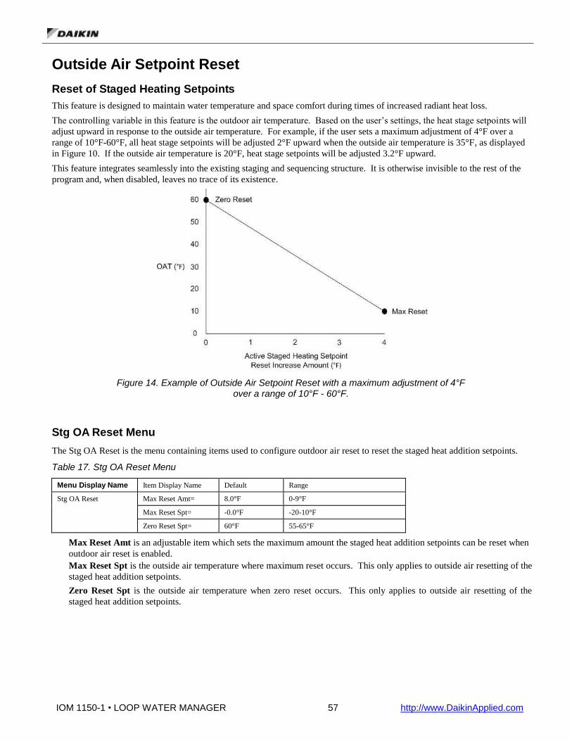
IOM 1150-1 • LOOP WATER MANAGER 57 http://www.DaikinApplied.com
Outside Air Setpoint Reset
Reset of Staged Heating Setpoints
This feature is designed to maintain water temperature and space comfort during times of increased radiant heat loss.
The controlling variable in this feature is the outdoor air temperature. Based on the user’s settings, the heat stage setpoints will
adjust upward in response to the outside air temperature. For example, if the user sets a maximum adjustment of 4°F over a
range of 10°F-60°F, all heat stage setpoints will be adjusted 2°F upward when the outside air temperature is 35°F, as displayed
in Figure 10. If the outside air temperature is 20°F, heat stage setpoints will be adjusted 3.2°F upward.
This feature integrates seamlessly into the existing staging and sequencing structure. It is otherwise invisible to the rest of the
program and, when disabled, leaves no trace of its existence.
Figure 14. Example of Outside Air Setpoint Reset with a maximum adjustment of 4°F over a range of 10°F - 60°F.
Stg OA Reset Menu
The Stg OA Reset is the menu containing items used to configure outdoor air reset to reset the staged heat addition setpoints.
Table 17. Stg OA Reset Menu
Menu Display Name Item Display Name Default Range
Stg OA Reset Max Reset Amt= 8.0°F 0-9°F
Max Reset Spt= -0.0°F -20-10°F
Zero Reset Spt= 60°F 55-65°F
Max Reset Amt is an adjustable item which sets the maximum amount the staged heat addition setpoints can be reset when
outdoor air reset is enabled.
Max Reset Spt is the outside air temperature where maximum reset occurs. This only applies to outside air resetting of the
staged heat addition setpoints.
Zero Reset Spt is the outside air temperature when zero reset occurs. This only applies to outside air resetting of the
staged heat addition setpoints.
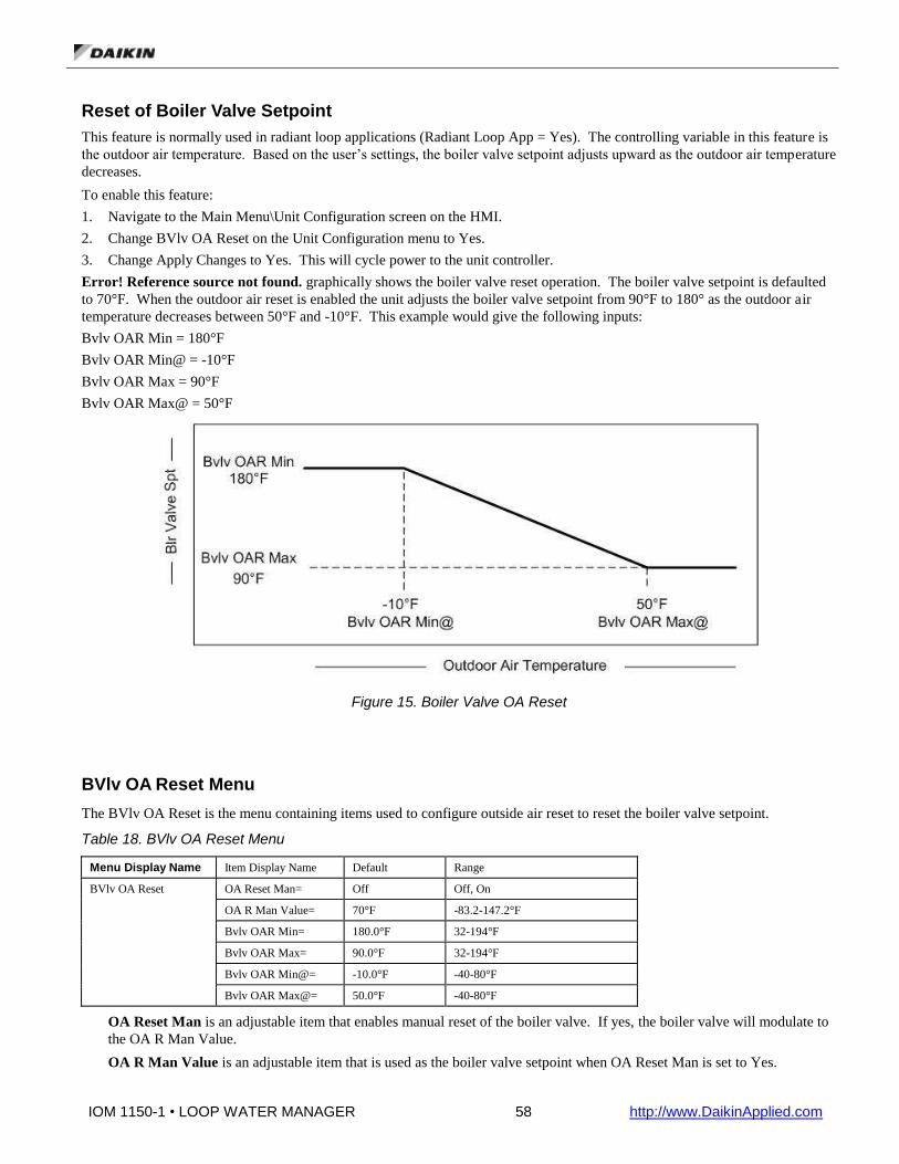
IOM 1150-1 • LOOP WATER MANAGER 58 http://www.DaikinApplied.com
Reset of Boiler Valve Setpoint
This feature is normally used in radiant loop applications (Radiant Loop App = Yes). The controlling variable in this feature is
the outdoor air temperature. Based on the user’s settings, the boiler valve setpoint adjusts upward as the outdoor air temperature
decreases.
To enable this feature:
1. Navigate to the Main Menu\Unit Configuration screen on the HMI.
2. Change BVlv OA Reset on the Unit Configuration menu to Yes.
3. Change Apply Changes to Yes. This will cycle power to the unit controller.
Error! Reference source not found. graphically shows the boiler valve reset operation. The boiler valve setpoint is defaulted
to 70°F. When the outdoor air reset is enabled the unit adjusts the boiler valve setpoint from 90°F to 180° as the outdoor air
temperature decreases between 50°F and -10°F. This example would give the following inputs:
Bvlv OAR Min = 180°F
Bvlv OAR Min@ = -10°F
Bvlv OAR Max = 90°F
Bvlv OAR Max@ = 50°F
Figure 15. Boiler Valve OA Reset
BVlv OA Reset Menu
The BVlv OA Reset is the menu containing items used to configure outside air reset to reset the boiler valve setpoint.
Table 18. BVlv OA Reset Menu
Menu Display Name Item Display Name Default Range
BVlv OA Reset OA Reset Man= Off Off, On
OA R Man Value= 70°F -83.2-147.2°F
Bvlv OAR Min= 180.0°F 32-194°F
Bvlv OAR Max= 90.0°F 32-194°F
Bvlv OAR Min@= -10.0°F -40-80°F
Bvlv OAR Max@= 50.0°F -40-80°F
OA Reset Man is an adjustable item that enables manual reset of the boiler valve. If yes, the boiler valve will modulate to
the OA R Man Value.
OA R Man Value is an adjustable item that is used as the boiler valve setpoint when OA Reset Man is set to Yes.

IOM 1150-1 • LOOP WATER MANAGER 59 http://www.DaikinApplied.com
Bvlv OAR Min is an adjustable item which sets the minimum boiler valve setpoint for use with an outdoor air reset
schedule.
Bvlv OAR Max is an adjustable item which sets the maximum boiler valve setpoint for use with an outdoor air reset
schedule.
Bvlv OAR Min@ is an adjustable item which sets the value of the outdoor air sensor at which the boiler valve setpoint is
reset to the boiler valve outside air reset minimum setpoint (Bvlv OAR Min) value.
Bvlv OAR Max@ is an adjustable item which sets the value of the outdoor air sensor at which the boiler valve setpoint is
reset to the boiler valve outside air reset maximum setpoint (Bvlv OAR Max) value.
Pump Control Menu
The Loop Water Manager is able to maintain control of and verify the water flow within the main water loop of the system. It
provides up to two digital outputs to start a field provided and wired main loop pump. An input from a field mounted flow
switch is monitored to determine if the pump achieves flow. If the main pump is activated, but does not achieve enough flow to
make the flow switch, a pump alarm is initiated and the pump output is deactivated. If the Loop Water Manager is configured
for a second main pump, it will attempt to start the second pump to achieve flow in the loop. In this dual main pump
configuration, the user may select which pump shall be the lead pump or select “auto”, in which the controller will automatically
select the pump with the least amount of run hours. If the second pump fails to achieve flow, it will also be shut down and the
Loop Water Manager will stay off in alarm, until the error(s) have been remedied and the alarms manually cleared at the LWM.
Additionally, the LWM can be configured to control up to two secondary pumps for a tower or boiler loop.
The Pump Control is the menu containing pump hours, the configuration point to select the lead pump and head pressure control
setpoints.
Table 19. Pump Control Menu
Menu Display Name Item Display Name Default Range
Pump Control Pump1 Hours= - 0-88000
Pump2 Hours= - 0-88000
Ld Pmp Select= Auto None, Pump1, Pump2, Auto
Sec Pump1 Hrs- - 0-88000
Sec Pump2 Hrs= - 0-88000
Ld Sec Pmp Select= Auto None, Pump1, Pump2, Auto
Pump1 Hours is the number of run hours for primary pump 1.
Pump2 Hours is the number of run hours for primary pump 2.
Ld Pmp Select configures which pump should start first.
None is used when there are no pumps.
Pump1 always start pump 1 first.
Pump2 always start pump 2 first.
Auto start whichever pump has the least run hours. This is only available if there is more than 1 pump.
Sec Pump1 Hours is the number of run hours for secondary pump 1.
Sec Pump2 Hours is the number of run hours for secondary pump 2.
Ld Sec Pmp Select configures which secondary pump should start first.
None is used when there are no pumps.
Pump1 always start pump 1 first.
Pump2 always start pump 2 first.
Auto start whichever pump has the least run hours. This is only available if there is more than 1 pump.
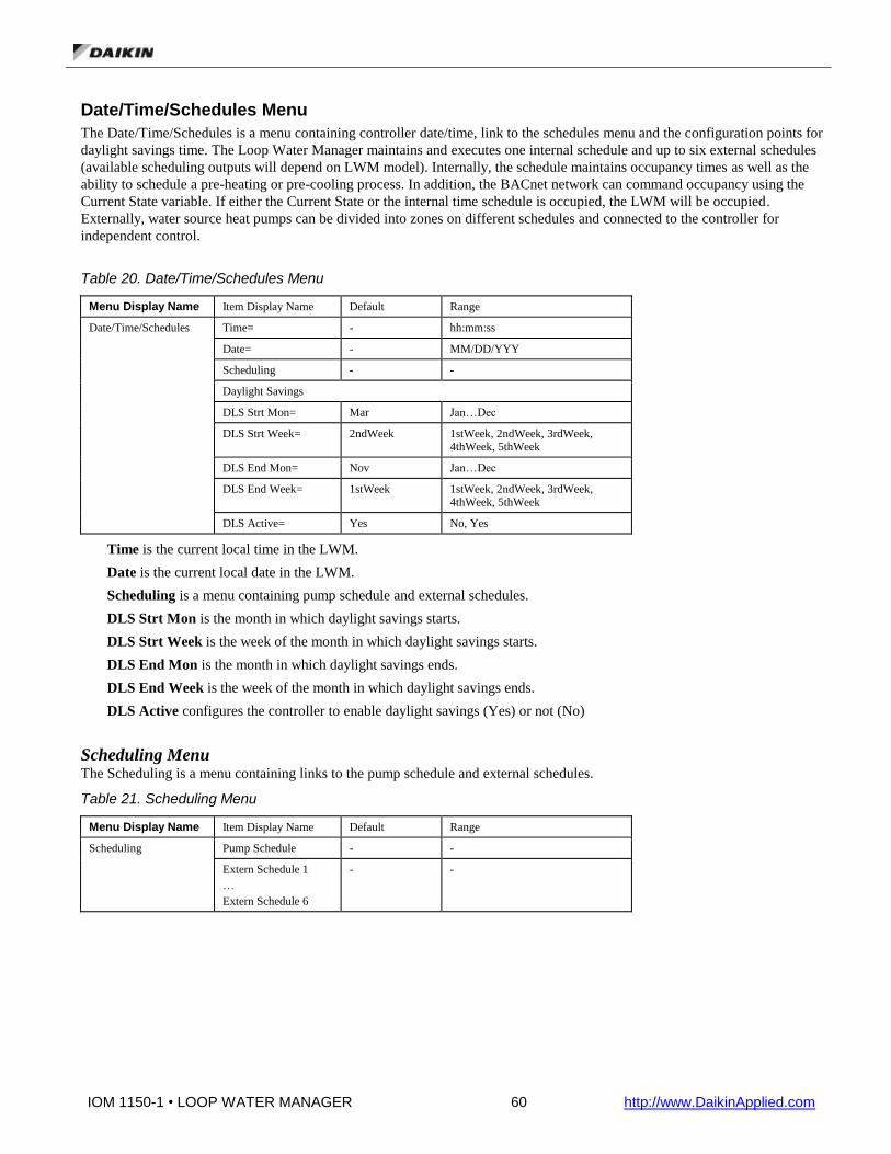
IOM 1150-1 • LOOP WATER MANAGER 60 http://www.DaikinApplied.com
Date/Time/Schedules Menu
The Date/Time/Schedules is a menu containing controller date/time, link to the schedules menu and the configuration points for
daylight savings time. The Loop Water Manager maintains and executes one internal schedule and up to six external schedules
(available scheduling outputs will depend on LWM model). Internally, the schedule maintains occupancy times as well as the
ability to schedule a pre-heating or pre-cooling process. In addition, the BACnet network can command occupancy using the
Current State variable. If either the Current State or the internal time schedule is occupied, the LWM will be occupied.
Externally, water source heat pumps can be divided into zones on different schedules and connected to the controller for
independent control.
Table 20. Date/Time/Schedules Menu
Menu Display Name Item Display Name Default Range
Date/Time/Schedules Time= - hh:mm:ss
Date= - MM/DD/YYY
Scheduling - -
Daylight Savings
DLS Strt Mon= Mar Jan…Dec
DLS Strt Week= 2ndWeek 1stWeek, 2ndWeek, 3rdWeek, 4thWeek, 5thWeek
DLS End Mon= Nov Jan…Dec
DLS End Week= 1stWeek 1stWeek, 2ndWeek, 3rdWeek, 4thWeek, 5thWeek
DLS Active= Yes No, Yes
Time is the current local time in the LWM.
Date is the current local date in the LWM.
Scheduling is a menu containing pump schedule and external schedules.
DLS Strt Mon is the month in which daylight savings starts.
DLS Strt Week is the week of the month in which daylight savings starts.
DLS End Mon is the month in which daylight savings ends.
DLS End Week is the week of the month in which daylight savings ends.
DLS Active configures the controller to enable daylight savings (Yes) or not (No)
Scheduling Menu The Scheduling is a menu containing links to the pump schedule and external schedules.
Table 21. Scheduling Menu
Menu Display Name Item Display Name Default Range
Scheduling Pump Schedule - -
Extern Schedule 1
…
Extern Schedule 6
- -

IOM 1150-1 • LOOP WATER MANAGER 61 http://www.DaikinApplied.com
Pump Schedule Menu The Pump Schedule is a menu used to configure the daily and holiday schedules for the pumps.
Table 22. Pump Schedule Menu
Menu Display Name Item Display Name Default Range
Pump Schedule
Extern Schedule 1…6
Mon: **:** - **:** 00:00-23:59
Tue: **:** - **:** 00:00-23:59
Wed: **:** - **:** 00:00-23:59
Thu: **:** - **:** 00:00-23:59
Fri: **:** - **:** 00:00-23:59
Sat: **:** - **:** 00:00-23:59
Sun: **:** - **:** 00:00-23:59
Holiday: **:** - **:** 00:00-23:59
Holiday Schedule - -
Extern Schedule 1...6 Menu The Extern Schedule 1…6 are menus used to configure the daily and holiday schedules for the external schedules.
Table 23. Extern Schedule 1…6 Menu
Menu Display Name Item Display Name Default Range
Pump Schedule
Extern Schedule 1…6
Mon: **:** - **:** 00:00-23:59
Tue: **:** - **:** 00:00-23:59
Wed: **:** - **:** 00:00-23:59
Thu: **:** - **:** 00:00-23:59
Fri: **:** - **:** 00:00-23:59
Sat: **:** - **:** 00:00-23:59
Sun: **:** - **:** 00:00-23:59
Holiday: **:** - **:** 00:00-23:59
Holiday Schedule - -
HolidaySchedules Menu The Holiday Schedules is a menu used to configure the 10 possible holiday schedules.
Table 24. Holiday Schedule Menu
Menu Display Name Item Display Name Default Range
Holiday Schedule Hol1=
…
Hol10=
**/**/** - **/**/**
-

IOM 1150-1 • LOOP WATER MANAGER 62 http://www.DaikinApplied.com
Commission Unit
Table 25. Commission Unit Menu
Menu Display Name Item Display Name Default Range
Commission Unit Eng Units= US US, SI
Loop Ctrl Tmp= Supply Supply, Return
Timer Settings - -
Safety Setpoints - -
IP Setup - -
Eng Units is used to set the units that are displayed by the keypad.
Loop Ctrl Tmp is used to set which temperature is used for control (Return or Supply).
Timer Settings Menu
The Timer Settings is the menu containing settings for various timers.
Table 26. Timer Settings Menu
Menu Display Name Item Display Name Default Range
Timer Settings Stage Time= 20s 0-600 seconds
Recirc Time= 180s 0-1800 seconds
Stage Time is the amount of time between heat addition/rejection stages.
Recirc Time is amount of time the unit status will remain in the Recirculate state when starting.
Safety Setpoints Menu
The Safety Setpoints is the menu containing critical alarm setpoints.
Table 27. Safety Setpoints Menu
Menu Display Name Item Display Name Default Range
Safety Setpoints SupHiTmpShutdn= 230.0°F -4.0-230.0°F
SupLoTmpShutdn= 35.0°F -4.0-230.0°F
RetHiTmpShutdn= 194.0°F -4.0-230°F
RetLoTmpShutdn= 25°F -4.0-230°F
HiTmp Emg Strt= 100°F 85°F - 115°F
LoTmp EmgStrt= 45°F 32°F - 60°F
Anti-Fz OA Spt= 35°F 20°F - 50°F
Loop SD Diff= 5°F 0°F - 15°F
Pump Fail Delay= 10s 0-600 seconds
HiPressFault= 725.2psi 0-7251.8psi
LoPressFault= 0.0psi 0-7251.8psi
SupHiTmpShutdn is the temperature at which the LWM will shut down if the supply temperature rises above it.
SupLoTmpShutdn is the temperature at which the LWM will shut down if the supply temperature goes below it.
RetHiTmpShutdn is the temperature at which the LWM will shut down if the return temperature rises above it.
RetLoTmpShutdn is the temperature at which the LWM will shut down if the return temperature goes below it.
HiTmp Emg Strt is the temperature at which the LWM will start (if unoccupied) if the outdoor air temperature rises above
it.
LoTmp Emg Strt is the temperature at which the LWM will start (if unoccupied) if the outdoor air temperature goes below
it.
Anti-Fz OA Spt is the temperature at which the LWM will start (if unoccupied) if the outdoor air temperature goes below
it. The unit will run in UnocLim state

IOM 1150-1 • LOOP WATER MANAGER 63 http://www.DaikinApplied.com
Loop SD Diff is the differential used to determine when emergency start is complete. For example, if the control temp is
greater than the HiTmp Emg Strt setpoint and the unit starts up, it needs to go below the HiTmp Emg Strt setpoint by more
than this differential to transition off again.
Pump Fail Delay is the amount of time the LWM will wait for the flow switch to make before turning off the pump on a
pump fail.
HiPressFault is the pressure at which a high pressure fault is generated.
LoPressFault is the pressure at which a low pressure fault is generated.
The IP Setup Menu
Table 28. IP Setup Menu
Menu Display Name Item Display Name Default Range
IP Setup Apply Changes= No No, Yes
Act IP= - -
ActMsk= - -
ActGwy= -
Gvn IP= - -
GvnMsk= - -
GvnGwy= -
DHCP Enabled? No No, Yes
WebUNm= ADMIN -
WebPwd= SBTAdmin! -
Apply Changes must be set to Yes after making any changes. Setting this to yes will cycle power to the controller to allow
the network setup changes to take place.
Act IP is the actual IP address of the BACnet communication module.
Act Msk is the actual Subnet Mask of the BACnet communication module.
ActGwy is the actual Gateway address.
GvnIP is the given IP address of the BACnet communication module.
GvnMsk is the given Subnet Mask of the BACnet communication module.
GvnGwy is the given Gateway address.
DHCP Enabled? is the Dynamic Host Configuration Protocol, a network protocol that enables a server to automatically
assign an IP address.

IOM 1150-1 • LOOP WATER MANAGER 64 http://www.DaikinApplied.com
Manual Control
The manual control of operation is a function that is used for operating the unit during a service call only. The unit must not be operated in this mode for any extended period of time.
Table 29. Manual Control Menu
Menu Display Name Item Display Name Default Range
Manual Control Manual Mode Act= No No/Yes
Pump1 Mode= Auto Off, Auto, On
Pump2 Mode= Auto Off, Auto, On
Pump 1 Drive= 0% 0-100%
Pump 2 Drive= 0% 0-100%
Sec Pump1 Mode= Auto Off, Auto, On
Sec Pump2 Mode= Auto Off, Auto, On
Tower Fan Drv= 0% 0-100%
Boiler Vlv Drv 0% 0-100%
Man Cool Stg= 0 0-12
Man Heat Stg= 0 0-12
Ena Twr Fan Man= Off Off, On
Twr Fan Man Open= Off Off, On
Twr Fan Man Close= Off Off, On
Blr Vlv Man Open= Off Off, On
Blr Vlv Man Close Off Off, On
Alarm LED Man= Off Off, On
EStop LED Man= Off Off, On
Lp Temp Simulate= 70.7°F -25.6-122°F
OAT Simulate= 70.7°F -25.6-122°F
Ex Sch 1 Man=
…
Ex Sch 6 Man=
Off Off, On

IOM 1150-1 • LOOP WATER MANAGER 65 http://www.DaikinApplied.com
Service Menus
Table 30. Service Menu
Menu Display Name Item Display Name Default Range
Timer Settings Stage Time= 20s 0-600 seconds
Recirc Time= 180s 0-1800 seconds
Operating Hours Pump1 Hours= - -
Pump2 Hours= - -
Sec Pump1 Hrs= - -
Sec Pump2 Hrs= - -
Save/Restore Settings Save Params= No No, Yes
Rstr Params= No No, Yes
SaveToCard= No No, Yes
LoadFromCard= No No, Yes
Active Alarms Alm Count:xx ClrAlms= No No, Yes
Alarm 1 … Alarms 10 - -
Alarm Log Log Count:xx Clr Log= No No, Yes
Alarm 1 … Alarm 50 - -
I/O Status Ext Flow Req= - Inactive, Active
Man Override= - Inactive, Active
Loop Pump1 Ena= - Off, On
Loop Pump2 Ena= - Off, On
Pump1 Drive= - 0-100%
Pump2 Drive= - 0-100%
Sec Lp Pmp1 Ena= - Off, On
Sec Lp Pmp1 Ena= - Off, On
Boiler Valve= - 0-100%
Tower Fan= - 0-100%
Heat Add Stage 1=
….
Heat Add Stage 12=
- Off, On
Heat Rej Stage 1=
….
Heat Rej Stage 12=
- Off, On
Ext Sched Out1=
…
Ext Sched Out6=
- Off, On
Twr Fan Ena Out= - Off, On
Alarm LED= - Off, On
Emg Stop LED= - Off, On
Local OAT= - -

IOM 1150-1 • LOOP WATER MANAGER 66 http://www.DaikinApplied.com
Unit Diagnostics Local I/O Diagnostics - -
Exp Mod A I/O Diag. - -
Exp Mod B I/O Diag. - -
Local I/O Diagnostics AI1= - -
AI2= - -
AI3= - -
DI1=
…
DI6=
- Off, On
DO1=
…
DO10=
- Off, On
X1=
…
X8=
- -
Exp Mod A I/O Diag.
Exp Mod B I/O Diag.
DI1= - Off, On
DO1=
…
DO6=
- Off, On
X1=
…
X8=
- -
Timer Settings is a menu containing configurable timers used in the LWM.
Stage Time is the amount of time between heat addition and heat rejection stages.
Recirc Time is the amount of time the LWM will remain in the recirculate state at startup.
Operating Hours is a menu containing the primary and secondary pump run hours.
Pump1 Hours is the number of runtime hours for pump 1.
Pump2 Hours is the number of runtime hours for pump 2.
Sec Pump1 Hrs is the number of runtime hours for secondary pump 1.
Sec Pump2 Hrs is the number of runtime hours for secondary pump 2.
Unit Maintenance
This menu gives the user access to the Operating Hours menu that contains the operating hours for the primary and secondary
pumps.
Table 31. Unit Maintenance Menu
Menu Display Name Item Display Name Default Range
Unit Maintenance Operating Hours - -
Operating Hours Pump1 Hours= - -
Pump2 Hours= - -
Sec Pump1 Hrs= - -
Sec Pump2 Hrs= - -
Operating Hours is the menu used to view run hours for the primary and secondary pumps.
Pump1 Hours is the number of runtime hours for pump 1.
Pump2 Hours is the number of runtime hours for pump 2.
Sec Pump1 Hrs is the number of runtime hours for secondary pump 1.
Sec Pump2 Hrs is the number of runtime hours for secondary pump 2.

IOM 1150-1 • LOOP WATER MANAGER 67 http://www.DaikinApplied.com
BMS Communications
Table 32. BMS Communications
Menu Display Name Item Display Name Default Range
BMS Communications BACnet MSTP Set-Up - -
Comm Slot 1= - None, IP, LON, MSTP, Modbus, DNET
Comm Slot 2= - None, IP, LON, MSTP, Modbus, DNET
Comm Slot 3= - None, IP, LON, MSTP, Modbus, DNET
BACnet MSTP Set-Up ApplyMSTPChgs= No No, Yes
Name= -
Dev Instance= - 0 – 4194303
MSTP Address= -
Baud Rate= 38400 9600, 19200, 38400, 76800
Max Master= 127 1-127
Max Info Frm= 1 1-32
Unit Support= English SI, English
Term Resistor= No No, Yes
NC Dev 1= 0 0 – 42949672
NC Dev 2= 0 0 – 42949672
Comm Status= -
Use Defaults= Off Off, On
RstOutOfSrvc= Done Done, False, True
BACnet BSP= 8.14 -
BACnet MSTP Set-up is the menu used to setup the parameters for the MS/TP communication module.
Comm Slot 1 defines the type of module located in the slot 1 position (closest to the main controller).
Comm Slot 2 defines the type of module located in the slot 2 position (second from the main controller).
Comm Slot 3 defines the type of module located in the slot 3 position (third from the main controller).
ApplyMSTPChgs causes the controller to reset, when set to yes, to allow the network setup changes to take effect.
Name is the Device Object Name. It must be unique throughout the entire BACnet network.
Dev Instance is the device instance of the BACnet Communication Module. It must be unique throughout the BACnet network.
MSTP Address is the MS/TP address of the BACnet Communication Module.
Baud Rate is the data transfer speed.
Max Master specifies the highest possible address for master nodes and shall be less than or equal to 127.
Max Info Frm specifies the maximum number of information frames the BACnet Communication Module may send before it
must pass the token.
Unit Support controls the type of units that are passed through BACnet (English or Metric).
Term Resistor is a software termination resistor, if MicroTech III controller is end of line an internal end of line resistor can be
programmed.
NC Dev 1 is the device instance of the BACnet workstation or device that will receive the alarm notification. Use this in place
of the Recipient List in the Notification Class.
NC Dev 2 is the device instance of the BACnet workstation or device that will receive the alarm notification. Use this in place
of the Recipient List in the Notification Class
Comm Status indicates the status of the BACnet Communication Module.
Use Defaults is used to determine the default BACnet setup values. If set to Off, the defaults will be gotten from the unit
controller. This can be useful when replacing a communication card.
RstOutOfSrvc will set the value of the Out of Service Property for setpoints.
BACnet BSP is the current version of firmware in the BACnet communication module

IOM 1150-1 • LOOP WATER MANAGER 68 http://www.DaikinApplied.com
Unit Configuration
After the LWM main control board software is loaded into the MCB, it must be “configured” for the specific control
application. This consists of setting the value of configuration variables within the MCB. These variables define things such as
the number of pumps, number of heating stages, and boiler valve output type, etc. If all of these items are not set appropriately
for the specific unit, the unit will not function properly. Once changes have been made to the Unit Configuration Menu, the
Apply Changes flag must be changed from ‘No’ to ‘Yes’ in order for the controller to recognize the changes. Setting the Apply
Changes flag to ‘Yes’ will automatically reset the controller.
Table 33. Unit Configuration Menu
Menu Display Name Item Display Name Default Range
Unit Configuration Apply Changes= No No, Yes
Radiant Loop App= No No, Yes
Main Lp Pmps= 2 None, 1, 2
Main Lp Fl Sw= 2 None, 1, 2
Sec Pmp Sw 1= None None, SecPmp1, Both
Sec Pmp Sw 2= None None, SecPmp2, Both
Sec Pmp1 Fnc= None None, Tower, Boiler
Sec Pmp2 Fnc= None None, Tower, Boiler
Avail Ht Stgs= None None, 1-12
Avail Cl Stgs= None None, 1-12
Pre Heat Ena= Disable Disable, Enabled
Pre Cool Ena= Disable Disable, Enabled
Blr Valve Act= None None, Analog
Blr Output Type= 0-10VDC 0-10VDC, 0-10Rev, 2-10VDC, 2-10Rev, 4-20mA, 4-20Rev
Twr Fan Act= None None, Analog
Twr Output Type= 0-10VDC 0-10VDC, 0-10Rev, 2-10VDC, 2-10Rev, 4-20mA, 4-20Rev
Lp Ret Sens= Disable Disable, Enabled
Head Press Sns= Disable Disable, Enabled
HdPres SnsType= None None, Current, 5VDC, 10VDC
Press Sns Rng= 500.0psi 24.5 to 750.6psi
OA Hum Sns Ena= Disable Disable, Enabled
OAH Sns Type= None None, Current, 5VDC, 10VDC
Blr Sensors= None None, Sup&Ret, Supply, Return
Tower Sensors= None None, Sup&Ret, Supply, Return
HeatXchr Sns= None None, Sup&Ret, Supply, Return
Geothermal Sns= Disable Disable, Enable
StrgTnk SnsEna= Disable Disable, Enabled
Damper I’lock= Disable Disable, Enabled
Ext Schedules= 1 1-6
StgHtg OA Reset= None None, Ntwrk, OAT
BVlv OA Reset= None None, Ntwrk, OAT
Sump Control= Yes No, Yes
Apply Changes= No No, Yes
Apply Changes must be set to ‘Yes’ after making any changes in this menu. It will cycle power to the unit controller.
Radiant Loop App defines whether or not this unit is used as a radiant loop application.

IOM 1150-1 • LOOP WATER MANAGER 69 http://www.DaikinApplied.com
Main Lp Pmps defines the number of main loop pumps.
Main Lp Fl Sw defines the number of main loop flow switches.
Sec Pmp Sw 1 enables the secondary loop flow switch 1.
Sec Pmp Sw 2 enables the secondary loop flow switch 2.
Sec Pmp 1 Fnc defines if pump 1 is a tower or boiler pump. If there is no secondary pump 1, this should be set to ‘None’.
Sec Pmp 2 Fnc defines if pump 2 is a tower or boiler pump. If there is no secondary pump 2, this should be set to ‘None’.
Avail Ht Stgs defines the number of heating stages (heat addition). If none, set to ‘None’.
Avail Cl Stgs defines the number of cooling stages (heat rejection). If none, set to ‘None’.
Pre Heat Ena enables or disables the pre heat functionality.
Pre Cool Ena enables or disables the pre cool functionality.
Blr Valve Act defines the type of boiler valve actuator. If none, set to ‘None’.
Twr Fan Act defines the type of tower fan actuator. If none, set to ‘None’.
Lp Ret Sens defines whether (enabled) or not (disabled) there is a loop return sensor present.
Head Press Sns defines whether (enabled) or not (disabled) there is a loop return sensor present.
HdPres SnsType defines the type of head pressure sensor.
Press Sns Rng defines the maximum output of the head pressure sensor.
OA Hum Sns Ena defines whether (enabled) or not (disabled) there is an outdoor air humidity sensor present.
OAH Sns Type defines the type of outdoor air humidity sensor.
Blr Sensors defines whether or not there are any boiler sensors (supply or return) present.
Tower Sensors defines whether or not there are any tower sensors (supply or return) present.
HeatXchr Sns defines whether or not there are any heat exchanger sensors (supply or return) present.
Geothermal Sns defines whether (enable) or not (disable) there is a geothermal temperature sensor present.
StrgTnk Sns Ena defines whether (enabled) or not (disabled) there is a storage tank sensor present.
Damper I’lock defines whether to enable or disable damper interlock.
Ext Schedules defines the number of external schedules. There will be one output for each schedule.
StgHtg OA Reset defines the method used to reset the staged heating setpoints based on outdoor air temperature setpoint.
None disables this feature.
Ntwrk the outdoor air temperature is written from the BACnet network.
OAT reset is based on the outdoor air temperature. See the Stg OA Reset menu for parameters.
BVlv OA Reset defines the method used to reset the boiler valve setpoint based on outdoor air temperature setpoint.
None disables this feature.
Ntwrk the outdoor air temperature is written from the BACnet network.
OAT reset is based on the outdoor air temperature. See the BVlv OA Reset menu for parameters.
Sump Control defines whether (Yes) or not (No) there is a sump to control.
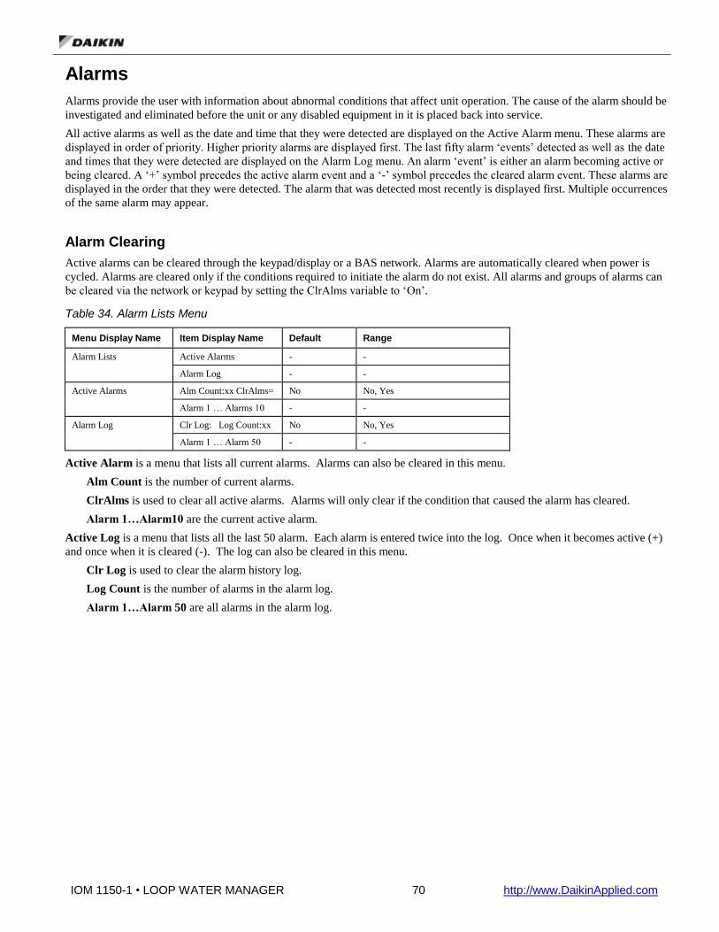
IOM 1150-1 • LOOP WATER MANAGER 70 http://www.DaikinApplied.com
Alarms
Alarms provide the user with information about abnormal conditions that affect unit operation. The cause of the alarm should be
investigated and eliminated before the unit or any disabled equipment in it is placed back into service.
All active alarms as well as the date and time that they were detected are displayed on the Active Alarm menu. These alarms are
displayed in order of priority. Higher priority alarms are displayed first. The last fifty alarm ‘events’ detected as well as the date
and times that they were detected are displayed on the Alarm Log menu. An alarm ‘event’ is either an alarm becoming active or
being cleared. A ‘+’ symbol precedes the active alarm event and a ‘-’ symbol precedes the cleared alarm event. These alarms are
displayed in the order that they were detected. The alarm that was detected most recently is displayed first. Multiple occurrences
of the same alarm may appear.
Alarm Clearing
Active alarms can be cleared through the keypad/display or a BAS network. Alarms are automatically cleared when power is
cycled. Alarms are cleared only if the conditions required to initiate the alarm do not exist. All alarms and groups of alarms can
be cleared via the network or keypad by setting the ClrAlms variable to ‘On’.
Table 34. Alarm Lists Menu
Menu Display Name Item Display Name Default Range
Alarm Lists Active Alarms - -
Alarm Log - -
Active Alarms Alm Count:xx ClrAlms= No No, Yes
Alarm 1 … Alarms 10 - -
Alarm Log Clr Log: Log Count:xx No No, Yes
Alarm 1 … Alarm 50 - -
Active Alarm is a menu that lists all current alarms. Alarms can also be cleared in this menu.
Alm Count is the number of current alarms.
ClrAlms is used to clear all active alarms. Alarms will only clear if the condition that caused the alarm has cleared.
Alarm 1…Alarm10 are the current active alarm.
Active Log is a menu that lists all the last 50 alarm. Each alarm is entered twice into the log. Once when it becomes active (+)
and once when it is cleared (-). The log can also be cleared in this menu.
Clr Log is used to clear the alarm history log.
Log Count is the number of alarms in the alarm log.
Alarm 1…Alarm 50 are all alarms in the alarm log.

IOM 1150-1 • LOOP WATER MANAGER 71 http://www.DaikinApplied.com
Fault Alarms (Highest Priority)
Faults are conditions that are serious enough to shut down the unit. The alarm must be manually cleared to allow unit operation.
Table 35. Fault Alarms in Order of Priority
Alarm Message Indication Clear
High Supply Temperature Fault The loop supply temperature is high. Manual
Low Supply Temperature Fault The loop supply temperature is low. Manual
High Return Temperature Fault The loop return temperature is the control temperature and is high. Manual
Low Return Temperature Fault The loop return temperature is the control temperature and is low. Manual
High Head Pressure The head pressure sensor has detected a dangerous high pressure condition.
Manual
Low Head Pressure The head pressure sensor has detected a dangerous low pressure condition.
Manual
Head Pressure Sensor Fault Head Pressure sensor is in error. Type of error – disconnect, short, etc – is not specified.
Manual
Outside Air Sensor Fault Outside Air Temp sensor is in error. Type of error – disconnect, short, etc. – is not specified.
Manual
Loop Return Sensor Fault Loop Return Temp sensor is in error. Type of error – disconnect, short, etc. – is not specified.
Manual
Loop Supply Sensor Fault Loop Supply Temp sensor is in error. Type of error – disconnect, short, etc. – is not specified.
Manual
Main Loop Pump Fail SD All available main loop pumps were activated and failed to establish flow. Auto-clears once all appropriate pump fail problems have cleared.
Automatic
Emergency Stop Emergency Stop Input in the Alarm (Open) condition. Automatic
Problem Alarms (Medium Priority)
Problems are conditions that result in some limitation of unit operation, but the unit is allowed to continue to operate. Some of
these alarms must be cleared manually, but others clear automatically.
Table 36. Problem Alarms in Order of Priority
Alarm Message Indication Clear
Main Loop Pump 2 Fail Main Loop Pump 2 was activated, but no flow was detected before FlowEstDelay timer expired.
Manual
Main Loop Pump 1 Fail Main Loop Pump 1 was activated, but no flow was detected before FlowEstDelay timer expired.
Manual
Boiler Pumps Fail All available secondary loop pumps that are configured as boiler pumps, were activated and failed to establish flow.
Automatic
Tower Pumps Fail All available secondary loop pumps that are configured as tower pumps, were activated and failed to establish flow.
Automatic
High Return Temperature Prob The loop return temperature is not the control temperature and is high. Manual
Low Return Temperature Prob The loop return temperature is not the control temperature and is low. Manual
Return Temp Sensor Problem The loop return temperature is not the control temperature and there is a problem with the sensor.
Manual
Warning Alarms (Lowest Priority)
Warnings inform the user of conditions that should be addressed, but do not limit operation in any way. The alarm condition
needs to be fixed and the alarm must be manually cleared to cause this alarm to no longer be active.
Table 37. Warning Alarms in Order of Priority
Alarm Message Indication Clear
UnoccLimProtect Loop Supply Temp exceeds bounds set by Water High Lim and Water Low Lim setpoints. Also triggered if Outdoor Air Temp has fallen below Anti-Freeze setpoint. Unit has entered UnoccLim state.
Automatic
SecPump2Manual Secondary Loop Pump 2 has been manually activated or deactivated, overriding any controller directives, and disregarding all alarms.
Automatic

IOM 1150-1 • LOOP WATER MANAGER 72 http://www.DaikinApplied.com
SecPump1Manual Secondary Loop Pump 1 has been manually activated or deactivated,
overriding any controller directives, and disregarding all alarms. Automatic
Pump2Manual Main Loop Pump 2 has been manually activated or deactivated, overriding any controller directives, and disregarding all alarms.
Automatic
Pump1Manual Main Loop Pump 1 has been manually activated or deactivated, overriding any controller directives, and disregarding all alarms.
Automatic
Secondary Loop Switch 2 Stuck Fail
Secondary Loop Flow Switch 2 is indicating flow, but Sec Pump 2 is not active.
Automatic
Secondary Loop Switch 1 Stuck Fail
Secondary Loop Flow Switch 1 is indicating flow, but no appropriate pump is active.
Automatic
Main Loop Switch 2 Stuck Fail Main Loop Flow Switch 2 is indicating flow, but Main Pump 2 is not active.
Automatic
Main Loop Switch 1 Stuck Fail Main Loop Flow Switch 1 is indicating flow, but no appropriate pump is active.
Automatic
Secondary Loop Pump 2 Fail Secondary Loop Pump 2 was activated, but no flow was detected before FlowEstDelay timer expired.
Manual
Secondary Loop Pump1 Fail Secondary Loop Pump 1 was activated, but no flow was detected before FlowEstDelay timer expired.
Manual
Tower Return Air Temp Fail Tower return air temperature sensor is enabled and failed. Automatic
Tower Supply Air Temp Fail Tower supply air temperature sensor is enabled and failed. Automatic
Storage Tank Temp Fail Storage tank temperature sensor is enabled and failed. Automatic
Geothermal Temp Fail Geothermal temperature sensor is enabled and failed. Automatic
Boiler Supply Temp Fail Boiler supply temperature sensor is enabled and failed. Automatic
Boiler Return Temp Fail Boiler return temperature sensor is enabled and failed. Automatic
Heat Exchanger Return Temp Fail
Heat exchanger return temperature sensor is enabled and failed. Automatic
Heat Exchanger Supply Temp Fail
Heat exchanger supply temperature sensor is enabled and failed. Automatic
OA Humidity Sensor Fail OA Humidity sensor is enabled and failed. Automatic
Emergency Control Activation
If, during a period of unoccupancy, ambient conditions bring the system into a state that may cause damage to the system if
allowed to continue, the LWM activates and works against that trend, bringing the system back into a more stable and safe
condition before returning to its unoccupied state.
This state is triggered by a user-settable parameter. Outdoor air and current loop water temperatures are taken into
consideration as to when to activate this state. Once active, the LWM will initiate temperature control until the system returns to
normal parameters.
This feature is a subset of the normal operation and requires no additional functional components or parameters beyond what is
already in place during normal occupied operation.
Emergency System Shutdown
It may occur that, during normal operation, a component malfunctions or the system enters a state from which there is no self-
repair. In these cases, the LWM ceases operation and generates an alarm.
System shutdown is a last-resort failure. Only the most extreme of situations should cause the system to cease operation. These
conditions are: failure of both main loop pumps to operate, operation failure of the loop control temperature sensor, excessively
high or low loop temperature, and excessively high or low loop water pressure, should the pressure sensor be present.

IOM 1150-1 • LOOP WATER MANAGER 73 http://www.DaikinApplied.com
About this LWM
Table 38. About this LWM Menu
Menu Display Name Item Display Name
About this LWM App Version=
Main BSP=
BACnet BSP=
HMI GUID=
OBH GUID=
App Version is the version of application code loaded into the controller
Main BSP is the current version of firmware in the main controller
BACnet BSP is the current version of firmware in the BACnet communication module
HMI GUID is the HMI software identifier number unique to each application code version
OBH GUID is the OBH software identifier number unique to each application code version
Unit State Transitions
Table 39. Unit State Transitions
Current State Conditions for transitioning to End State End State
Any State Control Mode is set to Off (default) via the keypad or the Control Mode is set to
Auto/Net and the Application Mode is set to Off via the network.
Off
Unocc Any condition detailed below leading from Recirc to any other state. Recirc
Recirc The recirc timer expires and the loop control temp is either less than the water low
limit setpoint or greater than the water high limit setpoint.
UnoccLim
Recirc The recirc timer expires and this is a scheduled PreCool period as defined by the time settings in the Pre Heat & Cool menu. In addition, the loop control temp must be greater than the PreCool setpoint plus PreCool differential and the outside air temp must be less than the PreCool outside air setpoint plus PreCool differential.
PreHeat
Recirc The recirc timer expires and this is a scheduled PreCool period as defined by the time settings in the Pre Heat & Cool menu. In addition, the loop control temp must be greater than the PreCool setpoint plus PreCool differential and the outside air temp must be less than the PreCool outside air setpoint plus PreCool differential.
PreCool
Recirc Recirc timer expires and either the Network Flow Request input or the Manual
Override input is active.
ExtFlowReq
Recirc The recirc timer expires and this is a scheduled occupancy period. The scheduled
occupancy will be occupied if either the local schedule indicates occupied or the
network is commanding the unit occupied through the Current State network
variable.
Occ
UnoccLim Loop Control Temp returns within bounds of High and Low Lim setpoints. Unocc
UnoccLim The controller enters a scheduled occupied period. The scheduled occupancy will
be occupied if either the local schedule indicates occupied or the network is
commanding the unit occupied through the Current State network variable.
Occ
UnoccLim The LWM enters a scheduled PreCool period as defined by the time settings in the Pre Heat & Cool menu. In addition, the loop control temp must be greater than the PreCool setpoint plus PreCool differential and the outside air temp must be less than the PreCool outside air setpoint plus PreCool differential.
PreHeat
UnoccLim The LWM enters a scheduled PreCool period as defined by the time settings in the Pre Heat & Cool menu. In addition, the loop control temp must be greater than the PreCool setpoint plus PreCool differential and the outside air temp must be less than the PreCool outside air setpoint plus PreCool differential.
PreCool
UnoccLim Either the Network Flow Request Input or Manual Override Input becomes active. ExtFlowReq
PreHeat The controller enters a scheduled occupied period. The scheduled occupancy will
be occupied if either the local schedule indicates occupied or the network is
commanding the unit occupied through the Current State network variable.
Occ

IOM 1150-1 • LOOP WATER MANAGER 74 http://www.DaikinApplied.com
PreHeat Either the Network Flow Request Input or Manual Override Input becomes active. ExtFlowReq
PreCool The controller enters a scheduled occupied period. The scheduled occupancy will
be occupied if either the local schedule indicates occupied or the network is
commanding the unit occupied through the Current State network variable.
Occ
PreCool Either the Network Flow Request Input or Manual Override Input becomes active. ExtFlowReq
ExtFlowReq External stimulus (Network Flow Request or Manual Override) that caused
transition released.
Unocc
ExtFlowReq The controller enters a scheduled occupied period. The scheduled occupancy will
be occupied if either the local schedule indicates occupied or the network is
commanding the unit occupied through the Current State network variable.
Occ
Any State
(except Manual) Loop Supply Temp < Loop Temp Low Shutdown OR
Loop Supply Temp > Loop Temp High Shutdown OR
Loop Control Temp < Loop Temp Low Shutdown OR
Loop Control Temp > Loop Temp High Shutdown OR
Head Pressure > High Pressure Shutdown OR
Head Pressure < Low Pressure Shutdown OR
Loop Supply Temp sensor disconnected OR
Head Pressure Sensor (if present) disconnected OR
Both Main Loop Pumps fail OR
Both Sec Loop Pumps fail OR
Emergency Stop digital input is made.
Alarm
Any State User activates Manual Mode. Manual
Manual User deactivates Manual Mode. Unocc

IOM 1150-1 • LOOP WATER MANAGER 75 http://www.DaikinApplied.com
BACnet Communication Module
Component Data
Figure 16 shows the location of the major components of the BACnet Communication Module.
Figure 16. BACnet Communication Module Components.
Light Emitting Diodes (LEDs)
The BACnet Communication Module has a BSP LED and a BUS LED to indicate communication activity and status of the
BACnet Communication Module. These indicators are visible when the communication module is connected to the Unit
Controller and the unit is powered on (see Figure 16).
BSP LED
The BSP LED indicates the communication state between the BACnet Communication Module and the Unit Controller. The
table below describes the status of the BSP LED.
BSP LED Color Meaning
Flashing between Red & Green Board Support Package (BSP) upgrade in progress
Green Communication is established between the communication
module and the unit controller.
Yellow The communication module is capable of communicating to
the unit controller. However, communication is not
established.
Red flashing with 2Hz Red flashing with 2Hz = Software error.1
Red Hardware error. 1
1 In the event that this should occur, cycle power to the unit controller to attempt to clear the problem. Contact the Daikin
Applied Controls Customer Support Group at 866-462-7829 for additional assistance if necessary.

IOM 1150-1 • LOOP WATER MANAGER 76 http://www.DaikinApplied.com
BUS LEDs
The BUS LED indicates the communication status between the BACnet Communication Module and the BACnet MS/TP
network. The table below describes the status of the BUS LED.
BUS LED Color Meaning
Green The unit controller is capable of communicating to the network.
Red The unit controller is not capable of communicating to the network.
Orange / Yellow Communication module is initializing.
BACnet Network Connector
An RS485 connector connects the BACnet Communication Module to the MS/TP Network and has three pins: + , -, and ref.
See Figure 16.
An RJ45 connector connects the BACnet Communication Module to the IP Network.
Board-To-Board Connector
The Board-to-Board Connector connects the Unit Controller to the BACnet Communication Module (see Figure 17 and Figure
18).
Figure 17. BACnet Communication Module and Knockout

IOM 1150-1 • LOOP WATER MANAGER 77 http://www.DaikinApplied.com
Figure 18. Diagram of Board-to-Board Connector
Figure 19. BACnet Communication Module with Board-to-Board Connector Inserted
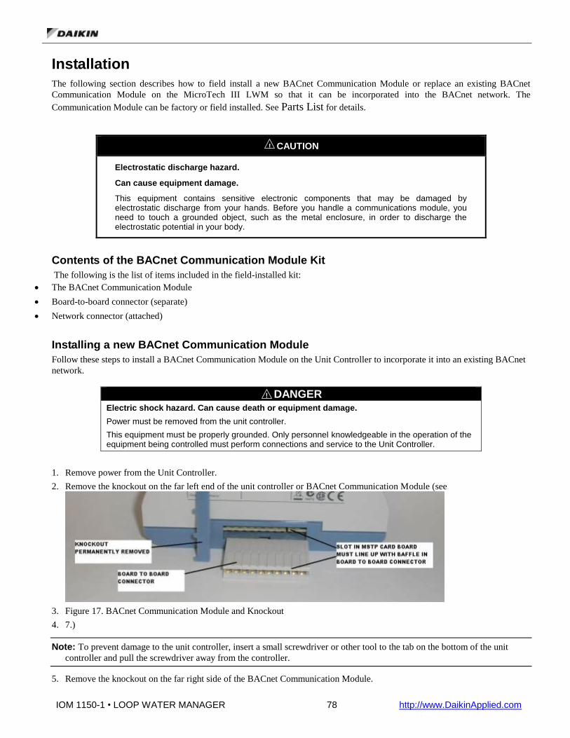
IOM 1150-1 • LOOP WATER MANAGER 78 http://www.DaikinApplied.com
Installation
The following section describes how to field install a new BACnet Communication Module or replace an existing BACnet
Communication Module on the MicroTech III LWM so that it can be incorporated into the BACnet network. The
Communication Module can be factory or field installed. See Parts List for details.
! CAUTION
Electrostatic discharge hazard.
Can cause equipment damage.
This equipment contains sensitive electronic components that may be damaged by electrostatic discharge from your hands. Before you handle a communications module, you need to touch a grounded object, such as the metal enclosure, in order to discharge the electrostatic potential in your body.
Contents of the BACnet Communication Module Kit
The following is the list of items included in the field-installed kit:
The BACnet Communication Module
Board-to-board connector (separate)
Network connector (attached)
Installing a new BACnet Communication Module
Follow these steps to install a BACnet Communication Module on the Unit Controller to incorporate it into an existing BACnet
network.
! DANGER
Electric shock hazard. Can cause death or equipment damage.
Power must be removed from the unit controller.
This equipment must be properly grounded. Only personnel knowledgeable in the operation of the equipment being controlled must perform connections and service to the Unit Controller.
1. Remove power from the Unit Controller.
2. Remove the knockout on the far left end of the unit controller or BACnet Communication Module (see
3. Figure 17. BACnet Communication Module and Knockout
4. 7.)
Note: To prevent damage to the unit controller, insert a small screwdriver or other tool to the tab on the bottom of the unit
controller and pull the screwdriver away from the controller.
5. Remove the knockout on the far right side of the BACnet Communication Module.
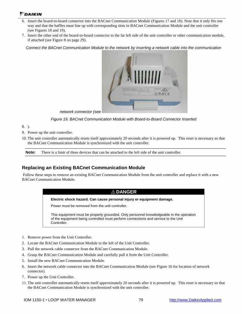
IOM 1150-1 • LOOP WATER MANAGER 79 http://www.DaikinApplied.com
6. Insert the board-to-board connector into the BACnet Communication Module (Figures 17 and 18). Note that it only fits one
way and that the baffles must line up with corresponding slots in BACnet Communication Module and the unit controller
(see Figures 18 and 19).
7. Insert the other end of the board-to-board connector to the far left side of the unit controller or other communication module,
if attached (see Figure 8 on page 29).
Connect the BACnet Communication Module to the network by inserting a network cable into the communication
network connector (see
Figure 19. BACnet Communication Module with Board-to-Board Connector Inserted
8. ).
9. Power up the unit controller.
10. The unit controller automatically resets itself approximately 20 seconds after it is powered up. This reset is necessary so that
the BACnet Communication Module is synchronized with the unit controller.
Note: There is a limit of three devices that can be attached to the left side of the unit controller.
Replacing an Existing BACnet Communication Module
Follow these steps to remove an existing BACnet Communication Module from the unit controller and replace it with a new
BACnet Communication Module.
! DANGER
Electric shock hazard. Can cause personal injury or equipment damage.
Power must be removed from the unit controller.
This equipment must be properly grounded. Only personnel knowledgeable in the operation of the equipment being controlled must perform connections and service to the Unit Controller.
1. Remove power from the Unit Controller.
2. Locate the BACnet Communication Module to the left of the Unit Controller.
3. Pull the network cable connector from the BACnet Communication Module.
4. Grasp the BACnet Communication Module and carefully pull it from the Unit Controller.
5. Install the new BACnet Communication Module.
6. Insert the network cable connector into the BACnet Communication Module (see Figure 16 for location of network
connector).
7. Power up the Unit Controller.
11. The unit controller automatically resets itself approximately 20 seconds after it is powered up. This reset is necessary so that
the BACnet Communication Module is synchronized with the unit controller.

IOM 1150-1 • LOOP WATER MANAGER 80 http://www.DaikinApplied.com
Integration
Once the BACnet Communication Module has been properly installed on the unit controller, it is then possible to integrate the
unit controller into a building automation system (BAS) via the BACnet IP or MS/TP network. The configuration process is
described in the following section.

IOM 1150-1 • LOOP WATER MANAGER 81 http://www.DaikinApplied.com
Connecting to the MicroTech Integrated System
Addressing
If the MicroTech III LWM is ordered with the MicroTech Integrated System, the BACnet MS/TP setup will be complete and
your controller can be wired directly to your system. If ordered separately, the BACnet IP or MS/TP addressing will need to be
setup prior to wiring it into the BACnet network. Check with your system integrator for correct addressing. See OM 1092 for
information regarding startup, operation and configuration of the MicroTech Integrated System.
Configuring the BACnet Communication Module
The BACnet Communication Module can be configured using the keypad/display on the Unit Controller. When ordered with a
MicroTech Integrated System, the network addressing should be pre-configured and should not require any field alterations.
The unit is ready to communicate the parameter values in the unit controller after you change the default parameters for your
particular network. Refer to Daikin Protocol Document ED 19015 for descriptions of the available BACnet objects.
BACnet IP Addressing
There are three parameters that must be configured properly to establish communication between the Unit Controller and the
BACnet IP network: BACnet IP Address, IP Subnet Mask, and IP Router Address. See your system integrator for additional
information regarding BACnet IP addressing. The BACnet Communication Module is DHCP (Dynamic Host Configuration
Protocol) enabled.
To Configure the Module using the Keypad/Display: 1. Navigate to the Enter Password screen if you have not already entered a password. If you have entered a password, skip to
step 3.
2. Enter Password: 6363.
3. Continue to navigate to BMS Communications\IP Setup.
Note: The IP Setup menu only appears if a BACnet Communication Module is installed correctly (see Installation section of
this document for details.) If the BACnet Communication Module is installed correctly and this menu still does not appear, cycle
power to the unit controller and repeat the procedure from Step 3 above.
4. Modify the parameters as necessary (see Table 40 for a complete list.)
5. To modify the Given IP Address, Given IP Mask, or Given IP Gateway, follow steps a-c below:
a. Fully change all four octets of the desired field.
Note: After entering all four octets of the desired field, the cursor should blink in the open space to the right of the last
character of the octet.
b. Select Enter by pressing down on the circular knob on the unit controller keypad. Do not press the Back button until
Enter has been selected.
c. From this screen, use the Back button to navigate to BMS Communications\IP Setup and change “ApplyIPChgs”
from ‘No’ to ‘Yes’.
6. Check that the network cable is connected and navigate to the IP Setup menu to verify the Actual IP Address. The Actual IP
Address displays 0.0.0.0 if the network cable is not attached. This procedure may take a minute while the BACnet
Communication Module powers up.
Configurable Parameters Table 40 defines the network parameters of the BACnet Communication Module that must be set using the keypad/display in
order to establish communication between the Unit Controller and the BAS. Change parameters as required for your network.
Note: To save alteration of these parameters, select “ApplyIPChgs” under BMS Communications/IP Setup (see Step 4 from
previous section).

IOM 1150-1 • LOOP WATER MANAGER 82 http://www.DaikinApplied.com
Table 40. Network Configuration Menu
Parameter Value (Range)/Definition Initial Value/Note
Apply IP Chg No-Yes/Apply IP Changes. Setting this to yes will cycle power to the controller to allow the network setup changes to take place.
No
Name Up to a 17-character Device Object Name. Change this value as needed to match installation parameters.
POL908_FF2BEE/This name must
be unique throughout the entire
BACnet network. The last 6
characters of the default are the
last 6 digits of the MAC Address,
which is printed on a label located
on the left end of the module.
“Apply IP Change” must be
activated for changes to the Device
Object Name to take effect.
Dev Instance 0-4194303/Device Instance of the BACnet Communication Module
1579312/ This must be unique throughout the entire BACnet network.
UDP Port (User Datagram Protocol) Identifies the application process in the destination unit
47808
DHCP Off-On/Dynamic Host Configuration Protocol (DHCP) is a network protocol that enables a server to automatically assign an IP Address
On/Set to Off if a static IP Address is needed.
Act IP Actual IP Address of the BACnet Communication Module
ActMsk Actual Subnet Mask of the BACnet Communication Module
ActGwy Actual Gateway Address
Gvn IP Given IP Address of the BACnet Communication Module
127.0.0.1
GvnMsk Given Subnet Mask of the BACnet Communication Module
255.255.255.0
GvnGwy Given Gateway Address 127.0.0.1
Unit Support Off-On/Controls the type of units that are passed through BACnet (English or Metric).
On/To set the unit for Metric, set Unit Support to Off. If Unit Support is On, they type of units will be set to the same units as the keypad.
NC Dev 1 0-4194303/Alarm Recipient Device 1 0 (no device)/This is the device instance of the BACnet workstation or device that will receive the alarm notification. Use this in place of the Recipient List in the Notification Class.
NC Dev2 0-4194303/Alarm Recipient Device 2 0 (no device)/This is the device instance of the BACnet workstation or device that will receive the alarm notification. Use this in place of the Recipient List in the Notification Class.
AHU Loc/Net Local-Network Network
Comm Status Ok, Hardware, Init, Memory, ID, COVReg, Other/Indicates the status of the BACnet module.
RstOutOfSrvc Done, False, True/Reset Out of Service will set the value of the Out of Service Property for setpoints.
Done
BACnetBSP Basic Support Package Version 9.26
IOM 1150-1 • LOOP WATER MANAGER 83 http://www.DaikinApplied.com
Note: If unit controller application software requires uploading in the field, the network configuration parameters revert to
their default values. Please contact the Applied Air Handling Customer Support Group at 763-553-5330 for
assistance with upgrading unit controller application software.
Test Procedures
If you can control the Unit Controller from the keypad/display, but you are not able to communicate via the network, follow
these steps:
Check the network wiring
Check communications
Use the standard TCP/IP suite of protocols to check your connectivity with other devices. For example, type “ping <IP address
of the MicroTech III BACnet Communication Module>.” If you get a response from that IP address, you are connected to the
BACnet Communication Module. If you do not get a response, verify the BACnet Communication Module and the PC network
settings.
Contact the Controls Customer Support Group at 866-462-7829 for additional assistance if necessary.
BACnet MS/TP Addressing
The BACnet MS/TP Media Access Control (MAC) address is a one-octet address that must be set during the BACnet
Communication Module configuration. The MAC address must be unique to the MS/TP network and have a valid range of 0-
127.
Additionally, there are certain parameters that must be set properly to verify communication between the LWM and the MS/TP
network. Table 41 provides details about these addressing parameters. See your system integrator for additional information
regarding proper BACnet MS/TP addressing.
To Configure the Module using the Keypad/Display:
1. Navigate to the Enter Password screen if you have not already entered a password. If you have entered a password, skip to step
3.
2. Enter Password: 6363.
3. Continue to navigate to BMS Communication\BACnet MSTP Set-Up.
Note: The BACnet MSTP Set-Up menu only appears if a BACnet Communication Module installed correctly (see
Installation section of this document for details.) If the BACnet Communication Module is installed correctly and this menu still
does not appear, cycle power to the unit controller and repeat the procedure from Step 3 above.
4. Modify the parameters as necessary
5. Continue to navigate to BMS Communication\BACnet MSTP Set-Up and change “ApplyMSTPChgs” from ‘No’ to ‘Yes’ (see
Figure 20).
6. On the MSTP Set-Up menu, verify the settings of all parameters. This procedure may take a minute while the BACnet
Communication Module powers up.

IOM 1150-1 • LOOP WATER MANAGER 84 http://www.DaikinApplied.com
Changing the MS/TP Data Transmission Rate
The options for baud rate (in bps) include: 9600, 19200, 38400, and 76800. The factory default baud rate is 38400 bps. If
connecting to a MicroTech Integrated System, the Baud Rate needs to match the Baud Rate on the Settings\Network Setup page.
The default for the MicroTech Integrated System is 38400.
! WARNING
Electric shock hazard. Can cause personal injury or equipment damage.
This equipment has exposed electrical connections inside BACnet Communication Module. Only personnel that are knowledgeable in the operation of this equipment must perform connections and service to the BACnet Communication Module.
Changing the MS/TP Data Transmission Rate:
1. Navigate to the Enter Password screen if you have not already entered a password. If you have entered a password, skip to
step 3.
2. Enter Password: 6363.
3. Navigate to the BMS Communication\BACnet MSTP Set-Up and change the baud rate to desired value (see Figure 21).
4. Continue to navigate to BMS Communication\BACnet MSTP Set-Up and change “ApplyMSTPChgs” from ‘No’ to ‘Yes’
(see Figure 20).
Figure 20. Unit Controller MSTP Setup Screen – Change “ApplyMSTPChgs”
Figure 21. Unit Controller MSTP Setup Screen – Change Baud Rate
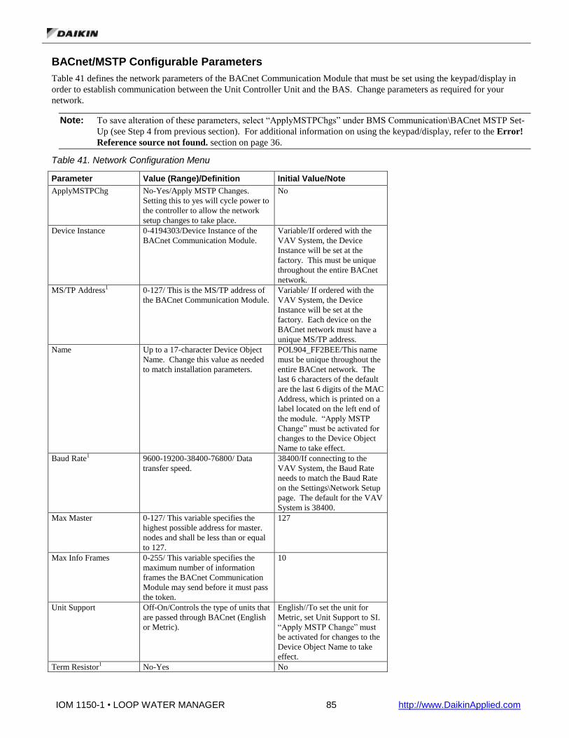
IOM 1150-1 • LOOP WATER MANAGER 85 http://www.DaikinApplied.com
BACnet/MSTP Configurable Parameters
Table 41 defines the network parameters of the BACnet Communication Module that must be set using the keypad/display in
order to establish communication between the Unit Controller Unit and the BAS. Change parameters as required for your
network.
Note: To save alteration of these parameters, select “ApplyMSTPChgs” under BMS Communication\BACnet MSTP Set-
Up (see Step 4 from previous section). For additional information on using the keypad/display, refer to the Error!
Reference source not found. section on page 36.
Table 41. Network Configuration Menu
Parameter Value (Range)/Definition Initial Value/Note
ApplyMSTPChg No-Yes/Apply MSTP Changes.
Setting this to yes will cycle power to
the controller to allow the network
setup changes to take place.
No
Device Instance 0-4194303/Device Instance of the
BACnet Communication Module.
Variable/If ordered with the
VAV System, the Device
Instance will be set at the
factory. This must be unique
throughout the entire BACnet
network.
MS/TP Address1 0-127/ This is the MS/TP address of
the BACnet Communication Module.
Variable/ If ordered with the
VAV System, the Device
Instance will be set at the
factory. Each device on the
BACnet network must have a
unique MS/TP address.
Name Up to a 17-character Device Object
Name. Change this value as needed
to match installation parameters.
POL904_FF2BEE/This name
must be unique throughout the
entire BACnet network. The
last 6 characters of the default
are the last 6 digits of the MAC
Address, which is printed on a
label located on the left end of
the module. “Apply MSTP
Change” must be activated for
changes to the Device Object
Name to take effect.
Baud Rate1 9600-19200-38400-76800/ Data
transfer speed.
38400/If connecting to the
VAV System, the Baud Rate
needs to match the Baud Rate
on the Settings\Network Setup
page. The default for the VAV
System is 38400.
Max Master 0-127/ This variable specifies the
highest possible address for master.
nodes and shall be less than or equal
to 127.
127
Max Info Frames 0-255/ This variable specifies the
maximum number of information
frames the BACnet Communication
Module may send before it must pass
the token.
10
Unit Support Off-On/Controls the type of units that
are passed through BACnet (English
or Metric).
English//To set the unit for
Metric, set Unit Support to SI.
“Apply MSTP Change” must
be activated for changes to the
Device Object Name to take
effect.
Term Resistor1 No-Yes No

IOM 1150-1 • LOOP WATER MANAGER 86 http://www.DaikinApplied.com
NC Dev 1 0-4194303/Alarm Recipient Device 1 0 (no device)/This is the device
instance of the BACnet
workstation or device that will
receive the alarm notification.
Use this in place of the
Recipient List in the
Notification Class.
NC Dev2 0-4194303/Alarm Recipient Device 2 0 (no device)/This is the device
instance of the BACnet
workstation or device that will
receive the alarm notification.
Use this in place of the
Recipient List in the
Notification Class.
Comm Status Ok, Hardware, Init, Memory, ID,
COVReg, Other/Indicates the status
of the BACnet module.
Use Defaults No-Yes No/If No, default values are
retained if module is replaced.
BACnetBSP Basic Support Package Version 8.14 1 Parameter only available via the keypad/display.
Note: If unit controller application software requires uploading in the field, the network configuration parameters revert to
their default values. Please contact the Daikin Applied Controls Customer Support group at 866-462-7829 for
assistance with upgrading unit controller application software.

IOM 1150-1 • LOOP WATER MANAGER 87 http://www.DaikinApplied.com
Controller Application Software Upgrade Procedures
Use this procedure to upgrade the MicroTech III controller application software in the Loop Water Manager. To load the files
into the controller, you will need an SD memory card no larger than 4GB with a FAT file system format.
Upgrading Firmware or Application Software
Note: Upgrading firmware or application software will result in all points being set back to their default values. Be sure to
record the configuration of the unit before proceeding so it can be restored once the upgrade is complete.
1. If the application code files & firmware files are compressed in a ZIP archive file, extract the files and place them in
the root directory of the SD memory card.
2. Insert the SD memory card into the controller’s memory card slot. The label on the card should be facing to the rear,
toward the controller.
Figure 22. SD Memory Card Slot
3. Power off the controller.
4. Make sure that all communication modules that need to be updated are connected.
5. Insert a small tool, such as the end of a 3/64" (1 mm) Hex Key or other similar tool with a narrow end, in the service hole
on the controller and hold the service button depressed.
6. While holding the service button depressed, power on the controller.
7. Continue depressing the service button until the BSP LED begins to flash between red and green.
BSP
LED Service Button
Figure 23. Service Button and BSP LED
8. Release the service button.
9. When all BSP LED’s on all modules have stopped flashing between red and green, power cycle the controller. Note: If
you have a communication module connected to the controller, wait for the controller to automatically reset
(approximately 30 seconds) before proceeding to the next step.
10. Configure your Loop Water Manager for your application.

IOM 1150-1 • LOOP WATER MANAGER 88 http://www.DaikinApplied.com
Troubleshooting Guide
Error! Reference source not found. summarizes several potential problems and corresponding solutions. Contact the Daikin
Applied Controls Customer Support group at 866-462-7829 for additional assistance.
Table 42. Common Problems and Solutions
Error/Condition Problem Solution
Keypad is missing data
and/or menus.
After changing the
configuration, you
must always cycle
power to the unit
controller.
Cycle power to the unit controller. This can
be done by setting the Apply Changes
parameter on the Unit Configuration menu to
‘Yes’.
Erroneous alarms for
inputs not connected or
being used.
LWM is alarming on
sensors and inputs not
being used in your
application
Verify the settings in the Unit Configuration
menu are appropriate. If so, select Apply
Changes and then select ‘Yes’. It can be
possible for configuration changes to be
made, but not applied. If no configuration
setting applies for the sensor in question, it is
likely a requirement for operation.
Outputs not energizing
field relays
Field relay coils are
not being energized by
output terminals from
the LWM, even though
the output is on.
Output terminals on the LWM are inherently
dry contacts from the factory. When wired in
a way that the output terminals on the LWM
are powered, the power source must be
provided by the field. See field wiring
section. Ensure the power source for these
outputs has enough VA to handle the load
from all field installed relay coils.
Red light on MCB There is a red light on
the MCB and no
display
Call Daikin Applied technical response; this
is typically an indication of a physical
problem with the controller.
Red light on EXPA-C There is a red light on
the expansion module
Verify the address is set properly (see I/O
section) on the expansion module and cycle
power. Call Daikin Applied technical
response if error still occurs.


IOM 1150-1 • LOOP WATER MANAGER 90 http://www.DaikinApplied.com
Service Information
Test Procedures
If you can control the unit from its keypad, but you are not able to communicate with unit via the network, follows these steps:
• Check the network wiring
• Check the network parameters and verify that they are correct and that there are no duplicate devices on the network
• Check communications
If the BACnet Communication Module still does not respond, contact the Daikin Applied Controls Customer Support Group at
866-462-7829.
Parts List
Component
Designation
Description
Part Number
MCB MicroTech III Controller with inbuilt HMI 193407301
BACNET BACnet/MSTP Communication Card 090016710
BACNET MicroTech III Communication Module, BACnet IP kit (kit includes communication module, board-to-board connector, and Installation Manual)
090016709
EXPA, EXPB, EXPC
MicroTech III Expansion Modules A, B, and C 193407501
T1 Transformer, Class II, 75VA, 120/24VAC 300041236
Terminal Block 2X2 Spring Grey, 2 Row Jumper Ports 349930641
Terminal Block 2X2 Spring Green (grounded terminals) 349930647
Terminal Block Jumper, 2 Pole 349930942
CB1 Circuit Breaker, 1-Pole, 10A, 120/240VAC 193431801
EXSC1-6, ES, SD, TF
Relay, 24VDC, 8A, DPDT 193592701
Relay Socket, DPDT 193592801
S3, S4 Selector Switch, 2 Position 193593001
PB1 Push Button 193592901
H1 Audible Alarm 193520501
L1 Pilot Light, Yellow, 24V LED 193520701
L2 Pilot Light, Red, 24V LED 193520601

IOM 1150-1 • LOOP WATER MANAGER 91 http://www.DaikinApplied.com
Daikin Applied Training and Development
Now that you have made an investment in modern, efficient Daikin equipment, its care should be a high
priority. For training information on all Daikin HVAC products, please visit us at www.DaikinApplied.com
and click on Training, or call 540-248-9646 and ask for the Training Department.
Warranty
All Daikin equipment is sold pursuant to its standard terms and conditions of sale, including Limited
Product Warranty. Consult your local Daikin Applied representative for warranty details. Refer to Form 933-
430285Y. To find your local Daikin Applied representative, go to www.DaikinApplied.com.
Aftermarket Services
To find your local parts office, visit www.DaikinApplied.com or call 800-37PARTS (800-377-2787).
To find your local service office, visit www.DaikinApplied.com or call 800-432-1342.
This document contains the most current product information as of this printing. For the most up-to-date
product information, please go to www.DaikinApplied.com.
Products manufactured in an ISO Certified Facility.