Embed Size (px)
Citation preview

Installation and Maintenance Manual IM 1059-11Group: WSHPPart Number: 910228803Date: January 2018
Enfinity™ Large Capacity Vertical Water Source Heat Pumps
LVC Standard Range & LVW Extended Range
Unit Sizes 072 – 290 (6 to 25 Tons) – R-410A Refrigerant

IM 1059-11 LARGE VERTICAL WSHP 2 www.DaikinApplied.com
Model Nomenclature . . . . . . . . . . . . . . . . . . . . . . . . . . 3Prior To Installing . . . . . . . . . . . . . . . . . . . . . . . . . . . . . 4
Receiving and storage . . . . . . . . . . . . . . . . . . . . . . . . 4Pre-installation . . . . . . . . . . . . . . . . . . . . . . . . . . . . . . 4
Installation Considerations . . . . . . . . . . . . . . . . . . . . . 5Unit location . . . . . . . . . . . . . . . . . . . . . . . . . . . . . . . . 5Fan deck arrangements . . . . . . . . . . . . . . . . . . . . . . . 5Vibration isolators . . . . . . . . . . . . . . . . . . . . . . . . . . . . 6Air balancing . . . . . . . . . . . . . . . . . . . . . . . . . . . . . . . . 7Sheave Adjustment . . . . . . . . . . . . . . . . . . . . . . . . . . . 7Ductwork and attenuation . . . . . . . . . . . . . . . . . . . . . . 8Ventilation air. . . . . . . . . . . . . . . . . . . . . . . . . . . . . . . . 8Accessory 2" deep filter rack kit with return air duct flange . . . . . . . . . . . . . . . . . . . . . . . . . . . . . . . . . . . . . 9
Unit Installation . . . . . . . . . . . . . . . . . . . . . . . . . . . . . . 11Piping . . . . . . . . . . . . . . . . . . . . . . . . . . . . . . . . . . . . 11Condensate Drain Connection . . . . . . . . . . . . . . . . . 12Typical Piping With Optional Waterside Economizer 13Typical WSE field provided and installed jumper piping routing details – LVC/LVW– sizes 072-120, right-hand . . . . . . . . . . . . 15LVC/LVW – sizes 072-120, left-hand. . . . . . . . . . . . . 16Typical WSE field provided and installed jumper piping routing details – LVC/LVW– sizes 180-290, right-hand . . . . . . . . . . . . 17LVC/LVW – sizes 180-290, left-hand. . . . . . . . . . . . . 18Water System Quality . . . . . . . . . . . . . . . . . . . . . . . . 19Cleaning & flushing system . . . . . . . . . . . . . . . . . . . . 20Operating limits . . . . . . . . . . . . . . . . . . . . . . . . . . . . . 20Electrical data . . . . . . . . . . . . . . . . . . . . . . . . . . . . . . 21Antifreeze correction factors . . . . . . . . . . . . . . . . . . . 22
Start-Up . . . . . . . . . . . . . . . . . . . . . . . . . . . . . . . . . . . . 23Start-up . . . . . . . . . . . . . . . . . . . . . . . . . . . . . . . . . . . 23Control options . . . . . . . . . . . . . . . . . . . . . . . . . . . . . 25MicroTech® III controller . . . . . . . . . . . . . . . . . . . . . . 26MicroTech III unit controller and I/O expansion module terminals, locations and descriptions . . . . . . . . . . . . 29MicroTech® III controller with LonWorks® or BACnet® communication module . . . . . . . . . . . . . . . . . . . . . . . 32
Typical Wiring Diagrams . . . . . . . . . . . . . . . . . . . . . . 33MicroTech III controller with I/O expansion module with hot gas reheat (HGRH) 208/230, 460, 575-60-3 (1.5 hp or less) . . . . . . . . . . 33MicroTech III controller with I/O expansion module with hot gas reheat (HGRH) 208/230, 460, 575-60-3 (greater than 1.5 hp) . . . . . . 34MicroTech III controller with I/O expansion module – with waterside economizer (WSE) 208/230, 460, 575-60-3. . . . . . . . . . . . . . . . . . . . . . . 35MicroTech III controller with I/O expansion module – with waterside economizer (WSE) 208/230, 460, 575-60-3. . . . . . . . . . . . . . . . . . . . . . . 36
Thermostats & Wall Sensors . . . . . . . . . . . . . . . . . . . 37Thermostat connections . . . . . . . . . . . . . . . . . . . . . . 37
Additional Accessories . . . . . . . . . . . . . . . . . . . . . . . 41Troubleshooting . . . . . . . . . . . . . . . . . . . . . . . . . . . . . 42
MicroTech III unit controller and I/O expansion module status LED's and fault outputs. . . . . . . . . . . . . . . . . . 42MicroTech III unit controller LED faults and remedy . 43I/O expansion module LED faults and remedy . . . . . 45Additional troubleshooting for size 290 only . . . . . . . 46Troubleshooting water source heat pump units . . . . 47
General Maintenance . . . . . . . . . . . . . . . . . . . . . . . . . 49Typical Refrigeration Cycles . . . . . . . . . . . . . . . . . . . 50
Water source heat pump equipment check, test and start form . . . . . . . . . . . . . . . . . . . . . . . . . . . . . . . . . . 53
Contents

Model noMenClature
Category Code Item Code Position Code Designation & Description
Product Category 01 1 W = Water Source Heat Pump
Product Identifier 02 2-4 LVC = R-410A, Floor Mounted, Standard Range LVW = R-410A, Floor Mounted, Extended Range
Design Series (Vintage) 03 5 1 = Design Series 1
Nominal Capacity 04 6-8 072 = 72,000 Btuh Nominal Cooling 096 = 96,000 Btuh Nominal Cooling 120 = 120,000 Btuh Nominal Cooling 180 = 180,000 Btuh Nominal Cooling 215 = 215,000 Btuh Nominal Cooling 290 = 290,000 Btuh Nominal Cooling
Control Board Option 05 9 B = MicroTech® III Unit Controller A = DDC-Less Board (Alerton Rep Option)
Network Module Option 06 10 L = Lon Module B = BACnet F = BACnet - WSHP System Y = None
Condensate Overflow Protection 07 11 S = Standard Overflow Sensor
Freeze Fault Protection 09 13 F = Freeze Fault Protection
Voltage 11 15 D = 208-60-3 H = 230-60-3 K = 460-60-3 L = 575-60-3
Return Air 13 17 Y = Front Return
Discharge Air 14 18 T = Top Horizontal Discharge U = Upblast Rear F = Upblast Front
Blower Motor 15 19-20 01 = Belt Drive – Integral HP Motor 02 = High Static
Construction Type 17 23 A = Standard 1/2" Fiberglass Insulation B = Closed Cell Foam Insulation F = Standard 1/2" Fiberglass Insulation w/Compressor Sound Blankets G = Closed Cell Foam Insulation w/Compressor Sound Blankets
Water To Refrigerant Heat Exchanger 18 24 C = Copper Inner Tube - Steel Outer TubeConstruction S = Cupro-nickel Inner Tube - Steel Outer Tube
Secondary Heating/Cooling Option 19 25 W = Waterside Economizer (Not to be combined with HGRH)
Dehumidification 20 26-27 AA = Hot Gas Reheat (Not to be combined with WSE) YY = None
Piping Hand 21 28 L = Left Side Pipe Connections R = Right Side Pipe Connections
Filter Options 23 32-34 SD1 = Standard 1" Disposable filter M08 = Merv 8 in 2" frame M13 = Merv 13 in 4" frame N02 = No Filter with 2" Filter Rack (Low Leak) N00 = No Filter-No Filter Rack
Condensate Drain Pan 27 41-42 GL = Galvanized Steel SS = Stainless Steel
Control Transformer Option 29 44-46 050 = 50VA Control Transformer 075 = 75VA Control Transformer
www.DaikinApplied.com 3 LARGE VERTICAL WSHP IM 1059-11

IM 1059-11 LARGE VERTICAL WSHP 4 www.DaikinApplied.com
Prior to installing
Receiving and storage CAUTION
Sharp edges can cause personal injury. Avoid contact with them. Use care and wear protective clothing, safety glasses and gloves when handling parts and servicing heat pumps.
Upon receipt of the equipment, check carton for visible damage. Make a notation on the shipper’s delivery ticket before signing. If there is any evidence of rough handling, immediately open the cartons to check for concealed damage. If any damage is found, notify the carrier within 48 hours to establish your claim and request their inspection and a report. The Warranty Claims Department should then be contacted.Do not stand or transport the machines on end. For storing, each carton is marked with “up” arrows.In the event that elevator transfer makes up-ended positioning unavoidable, do not operate the machine until it has been in the normal upright position for at least 24 hours.Temporary storage at the job site must be indoor, completely sheltered from rain, snow, etc. High or low temperatures naturally associated with weather patterns will not harm the units. Excessively high temperatures, 140°F (60°C) and higher, may deteriorate certain plastic materials and cause permanent damage.
IMPORTANTThis product was carefully packed and thoroughly inspected before leaving the factory. Responsibility for its safe delivery was assumed by the carrier upon acceptance of the shipment. Claims for loss or damage sustained in transit must therefore be made upon the carrier as follows:VISIBLE LOSS OR DAMAGEAny external evidence of loss or damage must be noted on the freight bill or carrier’s receipt, and signed by the carrier’s agent. Failure to adequately describe such external evidence of loss or damage may result in the carrier’s refusal to honor a damage claim. The form required to file such a claim will be supplied by the carrier.CONCEALED LOSS OR DAMAGEConcealed loss or damage means loss or damage which does not become apparent until the product has been unpacked. The contents may be damaged in transit due to rough handling even though the carton may not show external damages. When the damage is discovered upon unpacking, make a written request for inspection by the carrier’s agent within fifteen (15) days of the delivery date and file a claim with the carrier.
Pre-installation CAUTION
The installer must determine and follow all applicable codes and regulations. This equipment presents hazards of electricity, rotating parts, sharp edges, heat and weight. Failure to read and follow these instructions can result in property damage, severe personal injury or death. This equipment must be installed by experienced, trained personnel only.
1 . To prevent damage, do not operate this equipment for supplementary heating and cooling during the construction period.
2 . Inspect the carton for any specific tagging numbers indicated by the factory per a request from the installing contractor. At this time the voltage, phase and capacity should be checked against the plans.
3 . Check the unit size against the plans to verify that the unit is being installed in the correct location.
4 . Before installation, check the available ceiling height versus the height of the unit.
5 . Note the location and routing of water piping, condensate drain piping, and electrical wiring. The locations of these items are clearly marked on submittal drawings.
6 . The installing contractor will find it beneficial to confer with piping, sheet metal, and electrical foremen before installing any unit.
Note: Check the unit data plate for correct voltage with the plans before installing the equipment. Also, make sure all electrical ground connections are made in accordance with local code.
7 . The contractor shall cover the units to protect the machines during finishing of the building. This is critical while spraying fireproofing material on bar joists, sandblasting, spray painting and plastering. If plastic film is not available, the shipping carton may be modified to cover the units during construction.
8 . Remove all shipping blocks in the fan wheel.

installation Considerations
www.DaikinApplied.com 5 LARGE VERTICAL WSHP IM 1059-11
Unit locationLarge Vertical Water Source Heat Pump units are easily located in equipment rooms or floor-by-floor installations.They can be applied to all building types where it is advantageous to extend the water source heat pump concept to larger or core areas.Locate the unit in an area that allows for easy removal of the filter and access panels, and has enough space for service personnel to perform maintenance or repair. Provide sufficient room to make water, electrical and duct connections.Figure 1: Service clearances
Notes 1. A 12" (305 mm) minimum clearance is re-quired on the side opposite the pipe connec-tion side to gain access to panel to remove locking collar for shaft removal.
2. Top clearance is required for fan shaft removal.The contractor should make sure that access has been provided including clearance for 2" (51 mm) thick filter brackets, duct collars and fittings at water and electrical connections. Allow adequate room around the unit for a condensate trap. The unit can be installed “free standing” in an equipment room. Generally, the unit is located in a separate room with the non-ducted return air facing the return air intake. Alternatively, the unit can have a ducted return air. It is recommended that the unit be located on vibration isolators to reduce any vibration (see Figure 3 on page 6).
Fan deck arrangementsSix fan discharge arrangements and two piping arrangements are available. With the return air side defined as the “front” of the unit, the water piping connections may be right-hand (side) or left-hand. All units have a single supply and return water connection with a copper FPT type fitting that protrudes through the unit casing for easy connection. The condensate connection is
also a copper FPT type and is located on both sides of the unit. The unused connection is plugged.The main control panel is located in the center front of the unit. The fan discharge is top front, and the fan motor is always located at the piping end. Unit sides opposite the control panel and opposite the piping side may be up against walls and still allow for service and maintenance through the remaining access panels.Figure 2: Fan deck arrangements
Fan Motor
Rear (or Top) Discharge
Right-Hand Piping (Upblast-Rear)
Front (or Top) Discharge
Right-Hand Piping (Upblast-Front)
Front (or Top) Discharge
Left-Hand Piping (Upblast-Front)
Rear (or Top) Discharge
Left-Hand Piping (Upblast & Rear)
Straight Horizontal Discharge Left-Hand
Piping (Top-Horizontal Discharge)
Straight Horizontal Discharge Right-Hand Piping (Top-Horizontal
Discharge)
Notes: 1. The hand of unit is determined by looking at the return air (filter) side. The piping and electrical connections are always made on the “hand” side of the unit. The return air (fil-ter) side is considered the “front” of the unit.
2. The fan motor is always located at the piping/electrical connection (hand) side of the unit.

installation Considerations
IM 1059-11 LARGE VERTICAL WSHP 6 www.DaikinApplied.com
Vibration isolatorsFor minimum sound and vibration transmission, it is recommended that the unit be mounted on vibration isolators.Holes are provided in the bottom panel to facilitate connection of isolators (see Figure 4 & 5 for hole locations).Isolators supplied by the manufacturer are the type shown in Figure 3. Four white isolators are used for single compressor units and six green isolators are used for dual compressor units. The holes in the bottom of the unit allow for a 3⁄8" (10 mm) bolt to be secured to the isolator.
Figure 3: Vibration isolator dimensions
4½" (114 mm)5½" (140 mm)
2½" (64 mm)
2⅝" (61 mm)
7/16" (11 mm)
3/8" (10 mm) TAP
Figure 4: Vibration isolators locations - single compressor unit
3" (76 mm)
3" (76 mm)
3" (76 mm) 3" (76 mm)
Section A-A
2" (51 mm)
A A
285/32" (715 mm)
(4) 7/16" (11 mm) holes
7/16" (11 mm)
1/4" (6 mm)
5423/32" (1390 mm)
Figure 5: Vibration isolators locations - dual compressor unit
2" (51 mm)
2" (51 mm)
301/8" (765 mm)
31/4" (83 mm) 31/4" (83 mm)
(6) 3/8" (19 mm) holes
803/8" (2042 mm)
403/16" (1021 mm)

installation Considerations
www.DaikinApplied.com 7 LARGE VERTICAL WSHP IM 1059-11
Air balancingUnit sizes 072 thru 290 are supplied with a variable pitch motor sheave to aid in airflow adjustment.When the final adjustments are complete, the current draw of the motors should be checked and compared to the full load current rating of the motors. The amperage must not exceed the service factor stamped on the motor nameplate.
Sheave AdjustmentAdjusting Single Groove Sheave1 . All sheaves should be mounted on the motor or
driving shaft with the setscrew “X” toward the motor
2 . Fit shaft key “D” between sheave and shaft, and lock setscrew “X” in place. Wrench torque 110 in.-lb. minimum - 130 in.-lb. maximum.
3 . Be sure both driving and driven sheaves are in alignment and that shafts are parallel. Total axial and parallel misalignment must not exceed 1/4°
4 . Loosen setscrew “Y” in moving flange of sheave until movable flange is free to rotate.
5 . Adjust sheave pitch diameter for desired speed by opening rotating parts by half or full turn increments from closed position. Do not open more than five full turns.
6 . Tighten setscrew "Y" to 110 in.-lb. to 130 in.-lb. with setscrew "Y" located over center of casts flats on barrel of sheaves fixed component.
7 . Put on belts and adjust tension. (Do not force belts over grooves.) Check setscrews and belt tension after 24 hours of operation.
Figure 6: Sheave adjustment detail - single groove
XY
D
Adjusting 2-Groove Sheaves1 . All sheaves should be mounted on the motor or
driving shaft with the setscrew “X” toward the motor
1 . Loosen setscrews “Y” in moving flanges and pull out key “E”. (This key projects a small amount to provide a grip for removing).
2 . Rotate both movable flanges inward until they touch the center flange.
3 . Open each movable flange until its notch is adjacent to the notch on the center flange. Be certain that neither movable flange is opened more than one full turn.
4 . Open each movable flange the same number of full or half turns until the desired number of turns is obtained. Do not open more than five full turns.
CAUTIONFailure to adjust both equally may cause excessive vibration and blower assembly failure.
5 . Replace key “E” and tighten setscrews “Y”. Wrench torque 110 in.-lb. minimum - 130 in.-lb. maximum.
6 . Put on belts and adjust belt tension.(Do not force belts over flanges).
7 . Be sure that all keys are in place and that all setscrews are torqued properly before starting drive. Check setscrews and belt tension after 24 hours of operation.
Figure 7: Sheave adjustment detail - two groove
Y
X
Y
OD notched here.
E
Key “E” projects toprovide a grip forremoving
D
Figure 8: Drive belt adjustment
DeflectionForce
h
D
d
Span Length (t)
C t
64h =
C2 - D-d2
t = )(Where: t = Span length, inches (mm) C = Center distance, inches (mm) d = Smaller sheave diameter, inches (mm) h = Deflection height, inches (mm)Note: The ratio of deflection to belt span is 1:64.
installation Considerations
IM 1059-11 LARGE VERTICAL WSHP 8 www.DaikinApplied.com
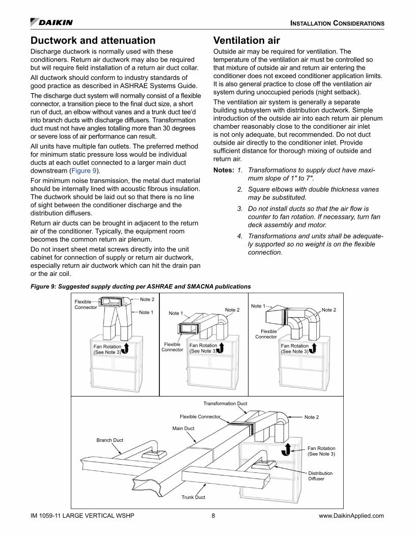
Ductwork and attenuationDischarge ductwork is normally used with these conditioners. Return air ductwork may also be required but will require field installation of a return air duct collar.All ductwork should conform to industry standards of good practice as described in ASHRAE Systems Guide.The discharge duct system will normally consist of a flexible connector, a transition piece to the final duct size, a short run of duct, an elbow without vanes and a trunk duct tee’d into branch ducts with discharge diffusers. Transformation duct must not have angles totalling more than 30 degrees or severe loss of air performance can result.All units have multiple fan outlets. The preferred method for minimum static pressure loss would be individual ducts at each outlet connected to a larger main duct downstream (Figure 9).For minimum noise transmission, the metal duct material should be internally lined with acoustic fibrous insulation. The ductwork should be laid out so that there is no line of sight between the conditioner discharge and the distribution diffusers.Return air ducts can be brought in adjacent to the return air of the conditioner. Typically, the equipment room becomes the common return air plenum.Do not insert sheet metal screws directly into the unit cabinet for connection of supply or return air ductwork, especially return air ductwork which can hit the drain pan or the air coil.
Ventilation airOutside air may be required for ventilation. The temperature of the ventilation air must be controlled so that mixture of outside air and return air entering the conditioner does not exceed conditioner application limits. It is also general practice to close off the ventilation air system during unoccupied periods (night setback).The ventilation air system is generally a separate building subsystem with distribution ductwork. Simple introduction of the outside air into each return air plenum chamber reasonably close to the conditioner air inlet is not only adequate, but recommended. Do not duct outside air directly to the conditioner inlet. Provide sufficient distance for thorough mixing of outside and return air.Notes: 1. Transformations to supply duct have maxi-
mum slope of 1" to 7". 2. Square elbows with double thickness vanes
may be substituted. 3. Do not install ducts so that the air flow is
counter to fan rotation. If necessary, turn fan deck assembly and motor.
4. Transformations and units shall be adequate-ly supported so no weight is on the flexible connection.
Figure 9: Suggested supply ducting per ASHRAE and SMACNA publications
Flexible Connector
Flexible Connector
Flexible Connector
Note 2
Note 2 Note 2Note 1
Note 1Note 1
Fan Rotation (See Note 3)
Transformation Duct
Flexible Connector
Main Duct
Branch Duct
Trunk Duct
Distribution Diffuser
Note 2
Fan Rotation (See Note 3)
Fan Rotation (See Note 3)
Fan Rotation (See Note 3)
installation Considerations
www.DaikinApplied.com 9 LARGE VERTICAL WSHP IM 1059-11
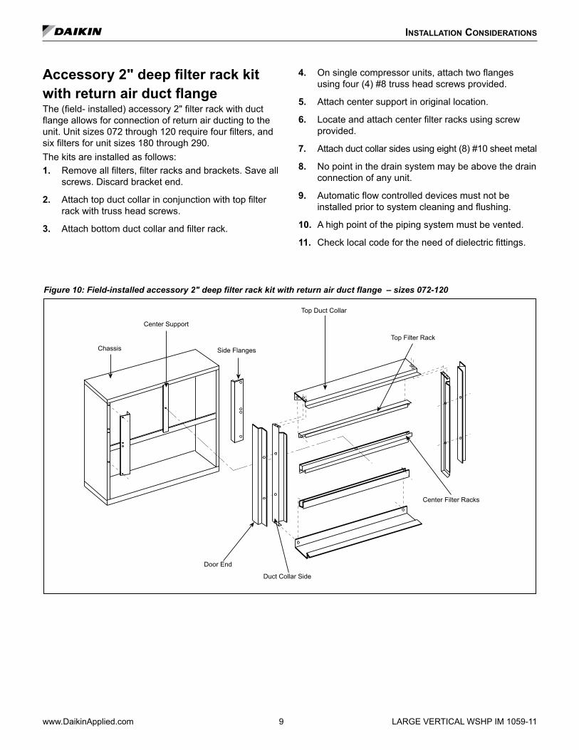
Accessory 2" deep filter rack kit with return air duct flangeThe (field- installed) accessory 2" filter rack with duct flange allows for connection of return air ducting to the unit. Unit sizes 072 through 120 require four filters, and six filters for unit sizes 180 through 290.The kits are installed as follows:1 . Remove all filters, filter racks and brackets. Save all
screws. Discard bracket end.
2 . Attach top duct collar in conjunction with top filter rack with truss head screws.
3 . Attach bottom duct collar and filter rack.
4 . On single compressor units, attach two flanges using four (4) #8 truss head screws provided.
5 . Attach center support in original location.
6 . Locate and attach center filter racks using screw provided.
7 . Attach duct collar sides using eight (8) #10 sheet metal
8 . No point in the drain system may be above the drain connection of any unit.
9 . Automatic flow controlled devices must not be installed prior to system cleaning and flushing.
10 . A high point of the piping system must be vented.
11 . Check local code for the need of dielectric fittings.
Figure 10: Field-installed accessory 2" deep filter rack kit with return air duct flange – sizes 072-120
Chassis
Center Support
Side Flanges
Top Duct Collar
Top Filter Rack
Center Filter Racks
Duct Collar Side
Door End

installation Considerations
Figure 11: Field-installed accessory 2" deep filter rack kit with return air duct flange – sizes 180-290
Chassis
Center SupportsTop Duct Collar
Top Filter Rack
Center Filter Racks
Duct Collar Side
Door End
Duct Collar Center Support
IM 1059-11 LARGE VERTICAL WSHP 10 www.DaikinApplied.com

unit installation
IM 1059-11 LARGE VERTICAL WSHP 11 www.DaikinApplied.com
Piping1 . All units should be connected to supply and return
piping in a two-pipe reverse return configuration. A reverse return system is inherently self-balancing and requires only trim balancing where multiple quantities of units with different flow and pressure drop characteristics exist in the same loop. Check for proper water balance by measuring differential temperature reading across the water connections. To insure proper water flow, the differential flow should be 10°F to 14°F (5°C to 8°C) for units in cooling mode. A direct return system may also work acceptably, but proper water flow balancing is more difficult to achieve and maintain.
2 . The piping can be steel or copper.
WARNINGPolyolester Oil, commonly known as POE oil is a synthetic oil used in many refrigeration systems. POE oil, if ever in contact with PVC/CPVC will coat the inside wall of PVC/CPVC pipe causing environmental stress fractures. It is recommended that PVC/CPVC piping is not used in the installation of the loop system, as system failure and property damage could result.
3 . Supply and return run-outs usually join the unit via short lengths of high pressure flexible hose which are sound attenuators for both unit operating noise and hydraulic pumping noise. One end of the hose should have a swivel fitting to facilitate removal for service. Hard piping can also be brought directly to the unit. This option is not recommended since no vibration or noise attenuation can be accomplished. The hard piping must have unions to facilitate unit removal. See Figure 12 for typical piping setup.
4 . Some flexible hose threaded fittings are supplied with sealant compound. If not, apply Teflon tape to assure a tight seal.
5 . Supply and return shutoff valves are required at each conditioner. The return valve is used for balancing and should have a “memory stop” so that it can always be closed off but can only be reopened to the proper position for the flow required.
6 . No unit should be connected to the supply and return piping until the water system has been cleaned and flushed completely. After the cleaning and flushing has taken place, the initial connection should have all valves wide open in preparation for water system flushing.
7 . Condensate piping can be steel, copper or PVC. Each unit includes a condensate connection.
Figure 12: Typical piping
Balancing Valve with Close-off
Shutoff Valve
Flexible Hoses
Condensate Drain with Trap and Clean-out
Water Return
Water Supply

www.DaikinApplied.com 12 LARGE VERTICAL WSHP IM 1059-11
unit installation
Condensate Drain ConnectionA field provided condensate trap must be installed on each water source heat pump. Condensate removal piping must be pitched away from the unit not less than 1/4" per foot. The vent should extend at least 1-1/4" above the unit condensate fitting. A vent is required after the trap so that the condensate will drain away from the unit. The vent can also act as a clean out if the trap becomes clogged. To avoid having waste gases entering the building, the condensate drain should not be directly piped to a drain/waste/vent stack. See local codes for the correct application of condensate piping to drainsFigure 13: Unit condensate drain pipe trap detail
Optional Field- Installed Vent
1-1⁄2" (38mm)
1-1⁄2" (38mm)
1⁄4" Per Foot (21mm Per Meter)
Note: Improper trapping can lead to several problems. If the trap is too tall, negative pressure will prevent drainage, causing condensate backup. If the trap is too short the seal will be destroyed or nonexistent, producing the same effect as a non-trapped system.
1 . Each water source heat pump is provided with a 3/4" FPT flush mount fitting for connection of a condensate drain. A complete copper or PVC condensate system can be used. Copper or steel condensate piping should be insulated to prevent sweating. In most applications the use of PVC prevents sweating of condensate drain.
2 . Do not locate any point in the drain system above the condensate drain connection of any unit.
It may be necessary to manually fill the trap at system startup, or to run the unit for sufficient time to build a condensate seal. The condensate trap and condensate piping drainage should be free of any foreign debris. Debris can prevent proper drainage and unit operation and result in condensate buildup.3 . Do not locate any point in the drain system above
the drain connection of any unit.
4 . Automatic flow controlled devices must not be installed prior to system cleaning and flushing.
5 . A high point of the piping system must be vented.
6 . Check local code for the need for dielectric fittings.
Figure 14: WSE condensate drain pipe detail
Vent

IM 1059-11 LARGE VERTICAL WSHP 13 www.DaikinApplied.com
unit installation
Typical Piping With Optional Waterside EconomizerWSE piping location dimensions – sizes 072-120
D (to center of drain)
Cr
E
H
As
K Br
LF M
G
J
WSE condensate drain connection 7/8" O.D.
1" FPT Supply water connection
1" FPT Return water connection
Vent access
Motorized valve access panel
Note: Piping connections from WSE return to unit supply to be field installed
Left-hand unit Right-hand unit
Cs
WSE piping location dimensions – sizes 180-290
D(to center of drain)
Cr
EH
As
K Br
LF M
G
J
WSE condensate drain connection 7/8" O.D.
1-1/2" FPT Supply water connection
Left-hand unit Right-hand unit
1-1/2" FPT Return water connection
Vent access
Motorized valve access panel
Note: Piping connections from WSE return to unit supply to be field installed
Cs
Unit SizeSupply & Return Connections Condensate
Drain 7/8" O .D .F G H J K L
M (filter rack)
As Br Cs Cr D E Stan-dard
Op-tional
072 – 1201 Left & right-hand 28.80 18.27 30.00 30.00 24.00 4.50 9.00 54.90 23.15 3.80 55.75 28.00
1.13"2.13"
or 4.13"180 – 2902
Left-hand 31.53 20.66 39.92 39.7526.18 4.50 16.00 80.63 25.33 5.10 67.25 30.00
Right-hand 32.13 20.39 39.92 41.16
Notes: 1 Supply and return piping connections = 1-1/4" FPT. 2 Supply and return piping connections = 1-1/2" FPT.

www.DaikinApplied.com 14 LARGE VERTICAL WSHP IM 1059-11
unit installation
Factory installed filter rack without duct flange (options) for large vertical units Standard 1" disposable filter
Merv 8 in 2" frame Merv 13 in 4" frame No filter with 2" filter rack (low leak) No filter-no filter rack
Field installed filter rack with return air duct flange (accessory) for large vertical units 2" filter rack with return air duct flange
A
B
C
Accessory 2" deep filter rack with return air duct flange
D
Table 1: Accessory filter rack with return air duct flange dimensions
Unit Size A BC
D Filters (quantity)2" deep
072-120 50.10" 30.90"2.29" 1"
4
180-290 74.10" 38.90" 6
Note: Dimensions are to outside edge of filter rack flange.

IM 1059-11 LARGE VERTICAL WSHP 15 www.DaikinApplied.com
unit installation
Typical WSE field provided and installed jumper piping routing details –LVC/LVW– sizes 072-120, right-hand
Front View 3.7" Max. dim.
1.7" Min. dim.
Right End View
WSE Supply
Unit Supply
Unit Return
Top View
WSE Return

unit installation
www.DaikinApplied.com 16 LARGE VERTICAL WSHP IM 1059-11
LVC/LVW – sizes 072-120, left-hand
Front View
Top View 7" Min. dim.
11" Max. dim.
Left End View
WSE Supply
Unit Supply
WSE Return

www.DaikinApplied.com 17 LARGE VERTICAL WSHP IM 1059-11
unit installation
Typical WSE field provided and installed jumper piping routing details –LVC/LVW– sizes 180-290, right-hand
WSE Supply
Unit SupplyUnit Return
WSE Return
Right End View
Top View
Front View 15" Min. dim.
19.85" Max. dim.

www.DaikinApplied.com 18 LARGE VERTICAL WSHP IM 1059-11
unit installation
LVC/LVW – sizes 180-290, left-hand
Front View
Top View
17" Min. dim.
10" Max. dim.
Left End View
WSE Supply
Unit Supply
WSE Return
Unit Return

IM 1059-11 LARGE VERTICAL WSHP 19 www.DaikinApplied.com
Water System QualityThe cleaning, flushing and chemical treatment of a water source heat pump system is fundamental to efficient operation and the life expectancy of the system.Potential system problems produced by the use of water fall into three general categories:• Scale formation – Mineral deposits which result from the
crystallization and precipitation of dissolved salts in the water. The deposits form an insulating barrier, reducing the heat transfer rate and impeding the circulation of fluids due to increased pressure drop.
• Corrosion – Decomposition of the metal caused by absorption of gases from the air. Corrosion may occur in any metal component of the system.
• Organic growths – Slime and algae which form under certain environmental conditions, and can reduce the heat transfer rate by forming an insulating coating or can promote corrosion by pitting.
The system water should be evaluated for degrees of impurity, with testing available from independent testing labs, health departments or state agencies. Table 2 is a list of water characteristics, the potential impurities and their results and the recommended treatment.
Avoiding Potential ProblemsAs shown in Table 2, all water contains some degree of impuri-ties which may affect the performance of a heat pump system. The use of a cupro-nickel coil can help avoid potential prob-lems. Water flow rates should:• Be high enough that the temperature rise through the heat
exchanger does not exceed 10° F when operating in the cooling mode.
• Not exceed 4 GPM per nominal ton. Flow rates that have velocities of 10 feet per second or more may cause pipe erosion and heat exchanger failure.
unit installation
Table 2: Water quality conditions & applications
Potential Problem Chemical(s) or Condition Range for Copper Heat Exchangers Range of Cupronickel Heat Exchanger
Scaling Calcium & Magnesium Carbonate Less than 350 ppm Less than 350 ppm
Corrosion
pH Range 7 – 9 5 – 9
Total Dissolved Solids Less than 1000 ppm Less than 1500 ppm
Ammonia, Ammonium Hydroxide Less than 0.5 ppm Less than 0.5 ppm
Ammonium Chloride, Ammonium Nitrate Less than 0.5 ppm Less than 0.5 ppm
Calcium Chloride/ Sodium Chloride Less than 125 ppm Less than 125 ppm - Note 4
Chlorine Less than 0.5 ppm Less than 0.5 ppm
Hydrogen Sulfide None Allowed None Allowed
Biological GrowthIron Bacteria None Allowed None Allowed
Iron Oxide Less than 1 ppm Less than 1 ppm
ErosionSuspended Solids Less than 10 ppm Less than 10 ppm
Water Velocity Less than 8 ft./s Less than 12 ft./s
Notes: 1. Water hardness in ppm is equivalent to hardness in mg/L. 2. Grains/gallon = ppm divided by 17.1. 3. Copper and cupronickel heat exchangers are not recommended for pool applications for water outside the range
of the table. Secondary heat exchangers are required for applications not meeting the requirements shown above. 4. Salt water applications (approx. 25,000 ppm) require secondary heat exchangers due to copper piping between the heat
exchanger and the unit fittings.

IM 1059-11 LARGE VERTICAL WSHP 20 www.DaikinApplied.com
Cleaning & flushing system1 . Prior to first operation of any conditioner, the water
circulating system must be cleaned and flushed of all construction dirt and debris. If the conditioners are equipped with water shutoff valves, either electric or pressure operated, the supply and return run-outs must be connected together at each conditioner location. This will prevent the introduction of dirt into the unit (Figure 15).
Figure 15: Supply & return run-outs connected together
Return Run-out
Supply Run-out
Mains
Flexible Hose
Run-outs Initially Connected Together
2 . Fill the system at the city water makeup connection with all air vents open. After filling, close all air vents. The contractor should start main circulator with the pressure reducing valve open. Check vents in sequence to bleed off any trapped air, ensuring circulation through all components of the system. Power to the heat rejector unit should be off, and the supplementary heat control set at 80°F (27°C).While circulating water, the contractor should check and repair any leaks in the piping. Drains at the lowest point(s) in the system should be opened for initial flush and blowdown, making sure city water fill valves are set to make up water at the same rate. Check the pressure gauge at pump suction and manually adjust the makeup to hold the same positive steady pressure both before and after opening the drain valves. Flush should continue for at least two hours, or longer if required, to see clear, clean drain water.
3 . Shut off supplemental heater and circulator pump and open all drains and vents to completely drain down the system. Short circuited supply and return run-outs should now be connected to the conditioner supply and return connections. Do not use sealers at the swivel flare connections of hoses.
4 . Trisodium phosphate was formerly recommended as a cleaning agent during flushing. However, many states and localities ban the introduction of phosphates into their sewage systems. The current recommendation is to simply flush longer with warm 80°F (27°C) water.
5 . Refill the system with clean water. Test the water using litmus paper for acidity, and treat as required to leave the water slightly alkaline (pH 7.5 to 8.5). The specified percentage of antifreeze may also be added at this time. Use commercial grade antifreeze designed for HVAC systems only. Do not use automotive grade antifreeze. Once the system has been filled with clean water and antifreeze (if used), precautions should be taken to protect the system from dirty water conditions. Dirty water will result in system wide degradation of performance and solids may clog valves, strainers, flow regulators, etc. Additionally, the heat exchanger may become clogged which reduces compressor service life or causes premature failure.
6 . Set the loop water controller heat add setpoint to 70°F (21°C) and the heat rejection setpoint to 85°F (29°C). Supply power to all motors and start the circulating pumps. After full flow has been established through all components including the heat rejector (regardless of season) and air vented and loop temperatures stabilized, each of the conditioners will be ready for check, test and start-up, air balancing, and water balancing.
Operating limitsInformation for initial start-up onlyStandard range units:Units are designed to start in an ambient of 50ºF (10ºC), with entering air at 50ºF (10ºC), with entering water at 70ºF (21ºC), with both air and water at the flow rates used in the ISO 13256-1 rating test, for initial start-up in winter.Note: This is not a normal or continuous operating
condition. It is assumed that such a start-up is for the purpose of bringing the building space up to occupancy temperature.
Extended range units:Extended range heat pump conditioners are designed to start in an ambient of 40ºF (5ºC), with entering air at 40ºF (5ºC), with entering water at 40ºF (5ºC), with both air and water at the flow rates used in the ISO 13256-1 rating test, for initial start-up in winter.Note: This is not a normal or continuous operating
condition. It is assumed that such a start-up is for the purpose of bringing the building space up to occupancy temperature.
unit installation

unit installation
www.DaikinApplied.com 21 LARGE VERTICAL WSHP IM 1059-11
EnvironmentThis equipment is designed for indoor installation only. Sheltered locations such as attics, garages, etc., generally will not provide sufficient protection against extremes in temperature and/or humidity, and equipment performance, reliability, and service life may be adversely affected.
Power supplyA voltage variation of +/-10% of nameplate voltage is acceptable. Three-phase system imbalance shall not exceed 2%.
Electrical dataGeneral1 . Verify the compatibility between the voltage and
phase of the available power and that shown on the unit serial plate. Line and low voltage wiring must comply with local codes or the National Electrical Code, whichever applies.
2 . Apply correct line voltage to the unit. A 7⁄8" (22mm) hole and/or a 1-1⁄8" (29 mm) knockout is supplied on the side of the unit. A disconnect switch near the unit is required by code. Power to the unit must be sized correctly and have dual element (Class RK5) fuses or an HACR circuit breaker for branch circuit over-current protection. See the nameplate for correct ratings.
3 . Three phase 50 cycle units require a neutral wire for 230/50-1 power to the fan circuit.
4 . Connect the thermostat/subbase wiring with the power “off ” to the unit.
5 . Field supplied relays installed on the input terminals W1, W2, Y1, Y2 or G may introduce electrical noise. Never install relay coils in series with the inputs.
Operating voltages208/230-60-1 ...............197 volts min.; 253 volts max.265-60-1 ......................238 volts min.; 292 volts max.230-50-1 ......................197 volts min.; 253 volts max.460-60-3 ......................414 volts min.; 506 volts max.575-60-3 ......................515 volts min.; 632 volts max.Note: Voltages listed are to show voltage range. However,
units operating with over-voltage and under-voltage for extended periods of time will experience premature component failure. Three phase system unbalance should not exceed 2%.
Table 3: Water source heat pump operating temperature limits (for continuous duty)
Operating Mode
Entering Air °F Entering Water °F
Minimum Maximum Standard Range Extended Range
DB WB DB WB Minimum Maximum Minimum Maximum
Cooling 65 55 85 71 55 110 50 110
Ambient 50 – 100 – – – – –
Heating 50 – 80 – 55 90 20 90
Ambient 50 – 85 – – – – –
Notes: 1. In the heating mode, the sum of the entering air + entering water must be ≥ 100°F.
2. MINIMUM WATER FLOW = 1.5 GPM/Ton.
3. Maximum and minimum values may not be combined. If one value is at maximum or minimum, the other two conditions may not exceed the normal condition for standard units. Extended range units may combine any two maximum conditions, but not more than two, with all other conditions being normal conditions.
Table 4: Water source heat pump operating temperature limits at start-up (not for continuous duty)
Operating Mode
Entering Air °F Entering Water °F
Minimum Maximum Standard Range Extended Range
DB WB DB WB Minimum Maximum Minimum Maximum
Cooling 50 40 105 87 45 120 30 120
Ambient 45 – 110 – – – – –
Heating 40 – 85 – 40 95 20 100
Ambient 40 – 85 – – – – –

unit installation
IM 1059-11 LARGE VERTICAL WSHP 22 www.DaikinApplied.com
Additional information for initial start-up standard range units LVCUnits are designed to start-up in an ambient of 50°F (10°C), with entering air at 50°F (10°C), with entering water at 70°F (21°C), with both air and water flow rates used in the ISO 13256-1 rating test, for initial start-up in winter.Note: This is not a normal or continuous operating condition.
It is assumed that such a start-up is for the purpose of bringing the building space up to occupancy temperature.
Extended range LVW unitsExtended range heat pump units are designed to start-up in an ambient of 50°F (10°C), with entering air at 40°F (10°C), with entering water at 25°F (-4°C), with both air and water at flow rates used in the ISO 13256-1 rating test, for initial start-up in winter.Note: This is not a normal or continuous operating condition.
It is assumed that such a start-up is for the purpose of bringing the building space up to occupancy temperature.
Antifreeze correction factorsTable 5: Ethylene glycol
10% 20% 30% 40% 50%
Cooling Capacity 0.9950 0.9920 0.9870 0.9830 0.9790
Heating Capacity 0.9910 0.9820 0.9770 0.9690 0.9610
Pressure Drop 1.0700 1.1300 1.1800 1.2600 1.2800
Table 6: Propylene glycol10% 20% 30% 40% 50%
Cooling Capacity 0.9900 0.9800 0.9700 0.9600 0.9500
Heating Capacity 0.9870 0.9750 0.9620 0.9420 0.9300
Pressure Drop 1.0700 1.1500 1.2500 1.3700 1.4200
Table 7: Methanol10% 20% 30% 40% 50%
Cooling Capacity 0.9980 0.9720 – – –
Heating Capacity 0.9950 0.9700 – – –
Pressure Drop 1.0230 1.0570 – – –
Table 8: Ethanol10% 20% 30% 40% 50%
Cooling Capacity 0.9910 0.9510 – – –
Heating Capacity 0.9950 0.9600 – – –
Pressure Drop 1.0350 0.9600 – – –
start-uP
www.DaikinApplied.com 23 LARGE VERTICAL WSHP IM 1059-11
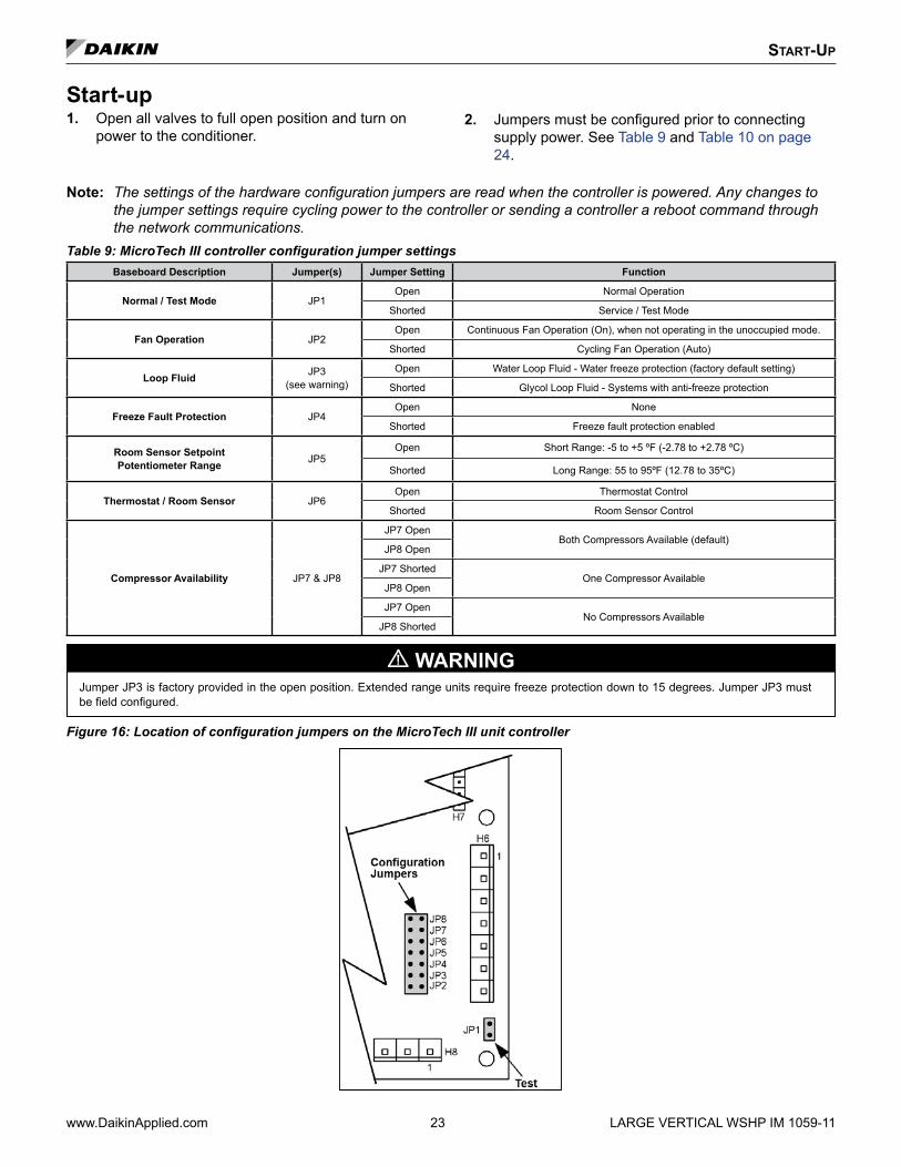
Note: The settings of the hardware configuration jumpers are read when the controller is powered. Any changes to the jumper settings require cycling power to the controller or sending a controller a reboot command through the network communications.
Table 9: MicroTech III controller configuration jumper settingsBaseboard Description Jumper(s) Jumper Setting Function
Normal / Test Mode JP1Open Normal Operation
Shorted Service / Test Mode
Fan Operation JP2Open Continuous Fan Operation (On), when not operating in the unoccupied mode.
Shorted Cycling Fan Operation (Auto)
Loop Fluid JP3(see warning)
Open Water Loop Fluid - Water freeze protection (factory default setting)
Shorted Glycol Loop Fluid - Systems with anti-freeze protection
Freeze Fault Protection JP4Open None
Shorted Freeze fault protection enabled
Room Sensor Setpoint Potentiometer Range JP5
Open Short Range: -5 to +5 ºF (-2.78 to +2.78 ºC)
Shorted Long Range: 55 to 95ºF (12.78 to 35ºC)
Thermostat / Room Sensor JP6Open Thermostat Control
Shorted Room Sensor Control
Compressor Availability JP7 & JP8
JP7 OpenBoth Compressors Available (default)
JP8 Open
JP7 ShortedOne Compressor Available
JP8 Open
JP7 OpenNo Compressors Available
JP8 Shorted
WARNINGJumper JP3 is factory provided in the open position. Extended range units require freeze protection down to 15 degrees. Jumper JP3 must be field configured.
Figure 16: Location of configuration jumpers on the MicroTech III unit controller
Start-up1 . Open all valves to full open position and turn on
power to the conditioner.2 . Jumpers must be configured prior to connecting
supply power. See Table 9 and Table 10 on page 24.

start-uP
Note: The settings of the hardware configuration jumpers are read when the controller is powered. Any changes to the jumper settings require cycling power to the controller or sending a controller a reboot command through the network communications.
Table 10: I/O expansion module jumper settingsI/O Expansion Description Jumper(s) Jumper Setting Model
Not Used JP1 JP1 Open –
Not Used JP2 JP2 Open –
Secondary HeatingOptions JP3 & JP4
JP3 OpenNone
JP4 Open
JP3 ShortedSupplemental Electric Heat
JP4 Open
JP3 OpenBoilerless Electric Heat
JP4 Shorted
Cooling / DehumidificationOptions JP5 & JP6
JP5 ShortedWithout Hydronic Cooling
JP6 Open
JP5 OpenHydronic Cooling (Waterside Economizer)
JP6 Shorted
Not Used JP7 JP7 Open –
Lead Compressor Option JP8JP8 Open Compressor #1 is Lead (factory default setting)
JP8 Shorted Compressor #2 is Lead
IM 1059-11 LARGE VERTICAL WSHP 24 www.DaikinApplied.com
Figure 17: I/O expansion module configuration jumper terminals
Jumper Terminals
3 . Set thermostat to “Cool”. If the thermostat is an automatic changeover type, simply set the cooling temperature to the coolest position. On manual changeover types additionally, select “Cool” at the system switch. Again, many conditioners have time delays which protect the compressor(s) against short cycling. After a few minutes of operation, check the discharge grilles for cool air delivery. Measure the temperature difference between entering and leaving water. It should be approximately 1½ times greater than the heating mode temperature difference. For example, if the cooling temperature difference is 15°F (8°C), the heating temperature difference should have been 10°F (5°C). Without automatic flow control valves, target a cooling temperature difference of 10°F to 14°F (5°C
to 8°C). Adjust the combination shutoff/balancing valve in the return line to a water flow rate which will result in the 10˚F to 14°F (5°C to 8°C) difference.
4 . Set thermostat to “Heat.” If the thermostat is the automatic changeover type, set system switch to the “Auto” position and depress the heat setting to the warmest selection. Some conditioners have built-in time delays which prevent the compressor from immediately starting. With most control schemes, the fan will start immediately. After a few minutes of compressor operation, check for warm air delivery at discharge grille. If this is a “cold building” start-up, leave unit running until return air to the unit is at least 65°F (18°C). Measure the temperature difference between entering and leaving air and entering and leaving water. With entering water of 60°F to 80°F (16°C to 27°C), leaving water should be 6°F to 12°F (3.3°C to 6.6°C) cooler (under full load conditions) and the air temperature rise through the machine should not exceed 35°F (19°C). If the air temperature exceeds 35°F (19°C), then the water flow rate is inadequate.
5 . Check the elevation and cleanliness of the condensate line. If the air is too dry for sufficient dehumidification, slowly pour enough water into the condensate pan to ensure proper drainage.
6 . If the conditioner does not operate, check the following points:
a. Is supply voltage to the machine compatible?
b. Is thermostat type appropriate?
c. Is thermostat wiring correct?

www.DaikinApplied.com 25 LARGE VERTICAL WSHP IM 1059-11
7 . If the thermostat operates but stops after a brief period:
a. Is there proper airflow? Check for dirty filter, incorrect fan rotation (3-phase fan motors only), or incorrect ductwork.
b. Is there proper water flow rate within temperature limits? Check water balancing; back-flush unit if dirt-clogged.
8 . Check for vibrating refrigerant piping, fan wheels, etc.
9 . Do not lubricate the fan motor during the first year of operation as it is pre-lubricated at the factory.
10 . Field supplied relays installed on the input terminals W1, W2, Y1, Y2 or G may introduce electrical noise. Never install relay coils in series with the inputs.
Control optionsThe control enclosure houses the major operating electrical controls including the MicroTech III controller and I/O expansion module, control transformer, compressor relays and fan relay. Each component is easily accessed for service or replacement.Three unique control choices are offered with the MicroTech III control system: Standalone operation using a MicroTech III
controller and I/O expansion module
MicroTech III controller with I/O expansion module and LonWorks® communication module
MicroTech III controller with I/O expansion module and BACnet® communication module
Each option features direct quick-connect wiring to all unit-controlled components for “clean” wiring inside the control box. Each control circuit board receives power from a 75 VA transformer.
start-uP
Figure 18: Control optionsControl Description Application Protocol
MicroTech III
(Standalone) Unit Controller with I/O Expansion Module
The MicroTech III controller is a standalone microprocessor-based control board conveniently located in the unit control enclosure for easy accessibility. The board is designed to provide thermostat control of a Water Source Heat Pump using a two-stage wall thermostat. The unit controller provides unit-wide control of the WSHP and control of the first refrigerant circuit.
Each unit controller is factory programmed, wired, and tested for complete control of single zone, standalone operation of your Daikin Water Source Heat Pump.
Unit-mounted or wall-mounted thermostat or room sensor
The I/O Expansion Module is an extension of the Microtech III controller and provides control of the second refrigerant circuit. External LED status lights display fault conditions to provide easy troubleshooting and diagnosis of the second circuit.
Allows for:
Control of second refrigeration circuit, secondary heating options and cooling/dehumidification options.
LonWorks
Communication Module
The MicroTech III control system accepts a plug-in LonWorks commu nication module to provide network communications and added functionality to easily integrate with an existing BAS. The communication module can be factory- or field-installed and is tested with all logic required to monitor and control the unit.
LonTalk application protocol is designed for units that are integrated into a LonWorks communication network for centralized scheduling and management of multiple heat pumps.
LonMark 3.4 Certified
BACnet
Communication Module
The MicroTech III controller accepts a plug-in BACnet commu nication module to provide network communications and added functionality to easily integrate with an existing BAS. The communication module can be factory- or field-installed and is tested with all logic required to monitor and control the unit.
Designed to be linked with a centralized building automation system (BAS) through a BACnet communications network for centralized scheduling and management of multiple heat pumps.
BACnet MS/TP
Controls
IM 1059-11 LARGE VERTICAL WSHP 26 www.DaikinApplied.com
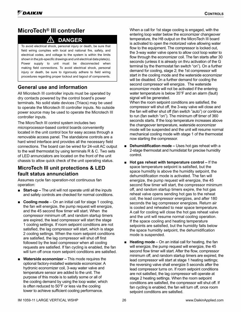
MicroTech® III controller DANGER
To avoid electrical shock, personal injury or death, be sure that field wiring complies with local and national fire, safety, and electrical codes, and voltage to the system is within the limits shown in the job-specific drawings and unit electrical data plate(s). Power supply to unit must be disconnected when making field connections. To avoid electrical shock, personal injury or death, be sure to rigorously adhere to field wiring procedures regarding proper lockout and tagout of components.
General use and informationAll Microtech III controller inputs must be operated by dry contacts powered by the control board’s power terminals. No solid state devices (Triacs) may be used to operate the Microtech III controller inputs. No outside power source may be used to operate the Microtech III controller inputs.The MicroTech III control system includes two microprocessor-based control boards conveniently located in the unit control box for easy access through a removable access panel. The standalone controls are a hard wired interface and provides all the necessary field connections. The board can be wired for 24-volt AC output to the wall thermostat by using terminals R & C. Two sets of LED annunciators are located on the front of the unit chassis to allow quick check of the unit operating status.
MicroTech III unit protections & LED fault status annunciationAssumes cycle fan operation-not continuous fan operation: Start-up – The unit will not operate until all the inputs
and safety controls are checked for normal conditions.
Cooling mode – On an initial call for stage 1 cooling, the fan will energize, the pump request will energize, and the 45 second flow timer will start. When the compressor minimum off, and random startup timers are expired, the lead compressor will start the stage 1 cooling settings. If room setpoint conditions are not satisfied, the lag compressor will start, which is stage 2 cooling settings. When the room setpoint conditions are satisfied, the lag compressor will shut off first followed by the lead compressor when all cooling requests are satisfied. If fan cycling is enabled, the fan will turn off once room setpoint conditions are satisfied.
Waterside economizer – This mode requires the optional factory-installed waterside economizer. A hydronic economizer coil, 3-way water valve and temperature sensor are added to the unit. The purpose of this mode is to satisfy some or all of the cooling demand by using the loop water, which is often reduced to 50°F or less via the cooling tower to achieve sufficient cooling performance.
When a call for 1st stage cooling is engaged, with the entering loop water below the economizer changeover temperature, the H8 output on the MicroTech III board is activated to open the motorized valve allowing water flow to the equipment. The compressor is locked out, the 3-way water valve opens to allow cool loop water to flow through the economizer coil. The fan starts after 30 seconds (unless it is already on thru activation of the G terminal by the thermostat fan switch “on”). On a further demand for cooling, stage 2; the 1st compressor will start in the cooling mode and the waterside economizer will be disabled. On a further demand for cooling the second compressor will energize. The waterside economizer mode will not be activated if the entering water temperature is below 35°F and an alarm (fault) signal will be generated. When the room setpoint conditions are satisfied, the compressor will shut off, the 3-way valve will close and the fan will either shut off (fan switch ”auto”) or continue to run (fan switch “on”). The minimum off timer of 360 seconds starts. If the loop temperature increases above the changeover temperature, waterside economizer mode will be suspended and the unit will resume normal mechanical cooling mode with stage 1 of the thermostat now starting the compressor.
Dehumidification mode – Uses hot gas reheat with a 2-stage thermostat and humidistat for precise humidity control.
Hot gas reheat with temperature control – If the space temperature setpoint is satisfied, but the space humidity is above the humidity setpoint, the dehumidification mode is activated. The fan will energize, the pump request will energize, the 45 second flow timer will start, the compressor minimum off, and random startup timers expire, the hot gas reheat valve opens sending hot gas to the reheat coil, the lead compressor energizes, and after 180 seconds the lag compressor energizes. Return air is cooled and reheated to near space temperature. A call for cooling will close the hot gas reheat valve and the unit will resume normal cooling operation. If the space cooling and heating temperature setpoints are satisfied, but the humidity falls below the space humidity setpoint, the dehumidification mode is suspended.
Heating mode – On an initial call for heating, the fan will energize, the pump request will energize, the 45 second flow timer will start. After the flow, compressor minimum off, and random startup timers are expired, the lead compressor will start at stage 1 heating settings; the reversing valve shall energize 5 seconds after the lead compressor turns on. If room setpoint conditions are not satisfied, the lag compressor will operate at stage 2 heating settings. When the room setpoint conditions are satisfied, the compressor will shut off. If fan cycling is enabled, the fan will turn off, once room setpoint conditions are satisfied.

Controls
www.DaikinApplied.com 27 LARGE VERTICAL WSHP IM 1059-11
Supplemental electric heat controlThe supplemental electric heating option provides additional stages of heating that can be used in conjunction with compressor heating, or exclusively if the compressor is not available for heating.
General rules• Supplemental electric heater and the compressor
may operate simultaneously. • Minimum compressor ON and OFF timers do not
apply to electric heat control.
OperationFan main output: will turn ON when:
• Any auxiliary heat output is energized.
• For 30 fixed seconds after all auxiliary heat outputs have been de-activated.
Electric heat outputs: are allowed to energize when either condition exists:
• Inter-stage ON timer must be expired.
• Compressor is not available for heating.
When compressor is available• Auxiliary heat stage #1 output energizes upon activation
of heating – stage #3.
• Auxiliary heat stage #2 output energizes upon activation of heating – stage #4.
When compressor is unavailable• Auxiliary heat stage #1 output energizes upon activation
of heating – stage #1.
• Auxiliary heat stage #2 output energizes upon activation of heating – stage #3.
Boilerless heat control –Turns on the heater when the entering water temperature is less than setpoint (default is 55°F), the temperature set point is adjustable through the network. For geothermal applications the heater turns on when the entering water temperature is less than setpoint (default 28°F).
Note: In both cases the compressor is shut down.
Short cycle protection & random start – After power cycle or deactivation of certain alarms, or when leaving the unoccupied mode, a new random compressor start-delay time between 300 and 360 seconds is generated. The random start timer prevents compressors in different units from starting simultaneously. Compressor minimum OFF 360 sec) and compressor minimum ON (180 sec) timers prevent compressor short cycling.
Unoccupied mode – A simple “grounded” signal between terminals U and C (no power source required), puts the unit into the unoccupied mode for night setback operation.
Inter-staging timer – A default value of 5 minutes between staging of compressors, this feature minimizes short cycling of compressors and improves comfort.
Override mode – A switch on the deluxe automatic changeover thermostat can be activated during the unoccupied mode to put the unit back into the occupied mode for two hours for after-hours heating or cooling.
Motorized valve/pump restart – The IV/PR (H8) terminals on the The MicroTech III unit controller are used to energize (open) a motorized valve or start a water pump to get water circulating prior to starting the compressor on call for heating or cooling. Lead compressor operation shall be delayed a minimum of 45 seconds, after the motorized valve/isolation valve output energizes to allow for supply water flow.
Brownout protection – The MicroTech III unit controller measures the input voltage and will suspend compressor and fan operation if the voltage falls below 80% of the unit nameplate rated value. Two external LED status are generated and an output is available to a "fault" LED at the thermostat.
Emergency unit shutdown – A simple grounded signal puts the unit into the shutdown mode. Remote shutdown is provided so that when properly connected to a water loop controller or remote switch, the emergency shutdown input can be used to shut down the water source heat pump. Compressor and fan operations are suspended, and an a unique two external LED status is generated.
Condensate overflow protection (cooling & dehumidification modes only) – The MicroTech III unit controller incorporates a liquid sensor at the top of the drain pan. When the unit senses a high condensate water level for 60 consecutive seconds while in the cooling or dehumidification modes the unit enters the "Off Alarm" machine state. The dehumidification or cooling mode operation will immediately be de-energized as well as the pump output.
Controls
Thermostat fault reset (preferred method) – A feature to reset some lockouts like high pressure and/or low temperature remote from the unit is available. When the cause of the fault condition has been fixed, repaired or resolved, the unit can be reset from the thermostat. To reset the fault, move the system switch on the thermostat from its current position (Heat/Auto/Cool) to the Off position and back to its original position two times within 30 seconds. The unit will now be reset. The intelligent reset counter and the 24 hour timer are cleared.
CAUTIONSome thermostats have internal timers greater than 30 seconds that delay their switching capabilities. Defeating their internal timers may be required to reset the fault using the thermostat.
Alternatively, thermostats shown in Figure 22 and Figure 23 on page 38 have an optional “reset” feature, by activating the reset feature and adding a wire from terminal O to terminal TB1, pin 4, on the MicroTech III board.
Reset of automatic lockouts (alternate method) - A feature to reset some lockouts like high pressure and/or low temperature at the unit is available. When the cause of the fault condition has been fixed, repaired or resolved, the unit can be reset at the unit. Apply a grounded signal to the tenant override input (screw terminal connection at TB1, pin 4) for a minimum of 10 seconds. The unit will now be reset. Alternatively, dropping power to the unit from the disconnect switch and re-applying power will reset the unit.
Intelligent alarm reset – The Intelligent Reset feature helps to minimize nuisance trips of automatic lockouts caused by low-temperature faults. This feature clears faults the first two times they occur within a 24-hour period and triggers an automatic lockout on the 3rd fault. The fault remains active until the alarm is manually cleared. At the end of the 24 hour period, all counts for that specific intelligent reset alarm are cleared to zero only if the occurrence counter is presently less than the value of three. The 24-hour period and alarm counts are stored in memory that is cleared when power is cycled.
Selectable lead compressor – The lead compressor selection provides a method to utilize circuit 2 if repairs are required on circuit 1. This is not intended for normal equipment operation. The jumper setting JP8 in the I/O expansion board is used to configure the “Lead Compressor” settings.
Lead compressor fail replacement – Upon detection of a lead compressor fault and the lag compressor is available, the selected lead compressor will be “failed replaced” by the lag compressor. Lead compressor will immediately be de-energized by ignoring the compressor minimum ON timer. Lag compressor will energize in place of the failed lead compressor, when the lag compressor minimum OFF timer has expired. Reversing valve for the lag compressor will be positioned, if necessary, 5 seconds after the lag compressor starts up.
Equipment protection control – The MicroTech III controller receives separate input signals from the refrigerant high-pressure switch and the low suction line temperature sensor. In a high-pressure situation, compressor operation is suspended. In a low temperature situation, the unit goes into a defrost cycle where the unit is put into cooling operation for 60 seconds until the coaxial heat exchanger is free of ice. Each switch generates its own unique LED status.
IM 1059-11 LARGE VERTICAL WSHP 28 www.DaikinApplied.com

Controls
www.DaikinApplied.com 29 LARGE VERTICAL WSHP IM 1059-11
MicroTech III unit controller and I/O expansion module terminals, locations and descriptionsTable 11: MicroTech III unit controller terminals locations and descriptions
H1 – 1 24 24 VAC Power Input
H1 – 2 C 24 VAC common
H2 – 1 SL1 Fan Main Output – Switched L1
H2 – 2 Blank Terminal
H2 – 3 N Fan Main Output – Neutral
H3 – 1 HP1-1 Comp High Pressure Switch (HP1) Input Terminal 1
H3 – 2 HP1-2 Comp High Pressure Switch (HP1) Input Terminal 2
H4 – 1 1 Discharge Air Temp Sensor – Common
H4 – 2 Discharge Air Temp Sensor – Signal
H4 – 3 Leaving Water Temp Sensor – Common
H4 – 4 Leaving Water Temp Sensor – Signal
H5 – 1 1 I/O Expansion Module Common (Gnd)
H5 – 2 I/O Expansion Module Common (Gnd)
H5 – 3 I/O Expansion Module +5 VDC
H5 – 4 I/O Expansion Module SPI CE1
H5 – 5 I/O Expansion Module SPI CLK
H5 – 6 I/O Expansion Module SPI OUT
H5 – 7 I/O Expansion Module SPI IN
H5 – 8 I/O Expansion Module +12 VDC
H5 – 9 I/O Expansion Module 24 VAC
H5 – 10 I/O Expansion Module 24 VAC
H5 – 11 No Connection
H5 – 12 No Connection
H6 – 1 1 Condensate Overflow Signal Input
H6 – 2 Compressor Suction Temp Sensor (LT1) – Common
H6 – 3 Compressor Suction Temp Sensor (LT1) – Signal
H6 – 4Compressor Low Pressure Switch (LP1) – Source Voltage
H6 – 5 Compressor Low Pressure Switch (LP1) – Signal
H6 – 6 Reversing Valve – Common
H6 – 7 Reversing Valve – Output
H7 – 1 1 No Connection
H7 – 2 No Connection
H7 – 3 Red LED Output
H7 – 4 Green LED Output
H7 – 5 Yellow LED Output
H7 – 6 Red-Green-Yellow LED Common
H8 – 1 1 Isolation Valve/Pump Request Relay N/O
H8 – 2 Isolation Valve/Pump Request Relay N/C
H8 – 3 24 VAC Common
H9 – 1 1 Return Air Temp – Signal
H9 – 2 Return Air Temp* – Common
TB1 – 1 1 Room Sensor – Status LED Output
TB1 – 2 2 Room Sensor – Fan Mode & Unit Mode Switches
TB1 – 3 3 Room Sensor – Setpoint Adjust Potentiometer
TB1 – 4 4Room Sensor – Room Temp Sensor & Tenant Override
TB1 – 5 5 Room Sensor – DC Signal Common
TB2 – 1 R 24 VAC
TB2 – 2 A Alarm Output
TB2 – 3 W2 Thermostat – Heat Stage #2 (W2) Input
TB2 – 4 W1 Thermostat – Heat Stage #1 (W1) Input
TB2 – 5 Y2 Thermostat – Cool Stage #2 (Y2) Input
TB2 – 6 Y1 Thermostat – Cool Stage #1 (Y1) Input
TB2 – 7 G Thermostat – Fan Input
TB2 – 8 O Thermostat – Heat Stage #3 (W3) Input
TB2 – 9 C 24 VAC Common
TB3 – 1 E Emergency Shutdown Input
TB3 – 2 U Unoccupied Input
L1 – 1 L1 - 1
24 VAC Power inL1 – 2 L1 - 2
L1 – 3 L1 - 3
N1 N1
24 VAC CommonN2 N2
N3 N3
CN_LON1 – 1 CN_LON1 GNDCN_LON1 – 2 + 5 VDCCN_LON1 – 3 SPI CE (SPI Select To Communications Board)CN_LON1 – 4 SPI CLK (Master Clock)CN_LON1 – 5 SPI OUT (MOSI)CN_LON1 – 6 SPI IN (MISO)CN_LON1 – 7 INT0 (SPI Ready To Baseboard)CN_LON1 – 8 No Connection
* Can have return air temperature sensor connected at H9 while the room sensor is connected to TB1, pin 4 (room temp sensor and ten-ant override)

Controls
Note: A random start delay time between 300 and 360 seconds is generated at power up.
Figure 19: MicroTech III unit controller terminal locations
IM 1059-11 LARGE VERTICAL WSHP 30 www.DaikinApplied.com

Controls
www.DaikinApplied.com 31 LARGE VERTICAL WSHP IM 1059-11
Table 12: I/O expansion module terminals locations and descriptions
H1 – 1 1 I/O Expansion Board Common (Gnd)
H1 – 2 I/O Expansion Board Common (Gnd)
H1 – 3 I/O Expansion Board +5 VDC
H1 – 4 I/O Expansion Board SPI CE1
H1 – 5 I/O Expansion Board SPI CLK
H1 – 6 I/O Expansion Board SPI IN
H1 – 7 I/O Expansion Board SPI OUT
H1 – 8 1 I/O Expansion Board +12 VDC
H1 – 9 I/O Expansion Board 24 VAC
H1 – 10 I/O Expansion Board 24 VAC
H1 – 11 No Connection
H1 – 12 No Connection
H2 – 1 1 Auxiliary Heat / Hydronic Heat Output – N/O
H2 – 2 No Connection
H2 – 3 24 VAC Common
H3 – 1 1 Ext. 24 VAC In
H3 – 2 Ext. 24 VAC Common In
H3 – 3 HGR / Waterside Economizer Output – N/O
H3 – 4 Ext. 24 VAC Common
H3 – 5 Fan Motor – Signal
H3 – 6 Fan Motor – Common
H4 – 1 1 Entering Water Temp Sensor – Signal
H4 – 2 Entering Water Temp Sensor – Common
H5 – 1 1 No Connection
H5 – 2 No Connection
H5 – 3 Red LED Output
H5 – 4 Green LED Output
H5 – 5 Yellow LED Output
H5 – 6 Red-Green-Yellow LED Common
H6 – 1 HP2-1 Comp #2 High Pressure Switch (HP2) Input Terminal 1
H6 – 2 HP2-2 Comp #2 High Pressure Switch (HP2) Input Terminal 2
H7 – 1 Comp #2 Suction Temp Sensor (LT2) – Signal
H7 – 2 Comp #2 Suction Temp Sensor (LT2) – Common
H7 – 3 Comp #2 Low Pressure Switch (LP2) – Signal
H7 – 4 Auxiliary 24VAC Output
H8 – 1 1 Compressor #2 Output – N/O
H8 – 2 24 VAC Common
H8 – 3 No Connection
H8 – 4 Reversing Valve #2 Output – N/O
H8 – 5 24 VAC Common
TB1 – 1 1 Humidistat (Dehumidification / WSE) Signal Input
TB1 – 2 2 Comp #2 Low Pressure Switch (LP2) – Signal
Figure 20: I/O expansion module terminals locations

Controls
IM 1059-11 LARGE VERTICAL WSHP 32 www.DaikinApplied.com
MicroTech® III controller with lonWorks® or BACnet® communication moduleEach Enfinity Large Horizontal Water Source Heat Pump can be equipped with a LonWorks or BACnet communication module. The LonWorks module is LonMark 3.4 certified and designed to communicate over a LonWorks communications network to a Building Automation System (BAS). The BACnet module is designed to communicate over a BACnet MS/TP communications network to a building automation system. Both communication modules are microprocessor-based and can be factory or field-installed.The communication modules are programmed and tested with all the logic required to monitor and control the unit. Optional wall sensors may be used with the communication modules to provide limited local control of the Horizontal Water Source Heat Pump. The MicroTech III controller monitors water and air temperatures and passes information to the communication module. The module communicates with the BAS, to provide network control of the Water Source Heat Pump.
MicroTech III lonWorks communication moduleThe LonWorks communication module is designed for units that are integrated into a LonWorks communication network for centralized scheduling and management of multiple heat pumps.
MicroTech III BACnet communication moduleDesigned to be linked with a centralized building automation system (BAS) through a BACnet communications network for centralized scheduling and management of multiple heat pumps.
MicroTech III controller with communication modules featuresThe MicroTech III Controller with LonWorks or BACnet Communication Module orchestrates the following unit operations: Enable heating and cooling to maintain space
temperature setpoint based on a room sensor setting
Enable fan and compressor operation
Monitors all equipment protection controls
Monitors room and discharge air temperatures
Monitors leaving water temperature
Relays status of all vital unit functions
An on-board status LED indicates the status of the MicroTech III LonWorks or BACnet module.The MicroTech III unit controller with communication module includes: Return Air Temperature sensor (RAT) (field-installed)
Discharge Air Temperature sensor (DAT) (field-installed)
Leaving Water Temperature sensor (LWT) (factory installed)
CAUTIONWhen an optional wall-mounted room temperature sensor is connected to the unit controller, the Return Air Temperature (RAT) sensor must not be installed. A wall-mounted room temperature sensor and the return air temperature sensor must not be connected simultaneously or the unit will not operate properly.
The communication modules provide network access to setpoints for operational control
Available wall sensors include: Room sensor
Room sensor with LED status and tenant override button
Temperature sensor with LED status, timed-override button; ±5°F setpoint adjustment
Room sensor with LED status, timed-override button, 55° to 95°F setpoint adjustment
Room sensor with digital display, timed override button, occupancy button; ±5°F setpoint adjustment or 55 to 95°F temperature setpoint and dehumidification control

tyPiCal Wiring diagraMs
MicroTech III controller with I/O expansion module with hot gas reheat (HGRH) 208/230, 460, 575-60-3 (1 .5 hp or less)
YE
L 14
BLU
15
LED
1
SLTS
RV LE
D1
GR
Y 46
BLU 41
BLU 40
RA
T
LED
2
IOE
XP
CO
S
BLK 60
BLK 61
SE
E N
OTE
BLU 21
LED
2
T1TB
1
YE
L
RE
D
L1
L2 L3
CM
-1
BLK
L1
T2
T3
L3L2
L1
SE
RV
ICE
&D
ISC
ON
NE
CTL3
L2
YEL 18
JP_2
JP_3
JP_4
JP_5
JP_6
JP_7
JP_8
H1
H2 N3
N2
N1
L1-3
L1-2
L1-1
H3
H5
H4
H7
H6
H8
H9
TB2
TES
T-1
TB1
TB3
RU
N P
RG
JTAG
BLU 20
LP2
HP
2
SLTS
2
1 11 1
1JP
1JP
8
JTAG
RV
2
YE
L 11
RE
D 12
CC
1BLK 1
YEL 2
RED 3
BR
N 52
BR
N 53
BLU
42B
LU 43
BLK
62
BLK
63
YE
L 19
LP
T3
BLK
10
YE
L 8 (L2)
RE
D 9 (L3)
R1
HP
BR
N 55
BR
N 54
GRN/YEL 97
FAN
MO
TOR
LWT
DA
T
YE
L
BLU
YE
L 45
EW
T
BLK/RED-460VRED-208VORG-230VBLK-575V
1
RE
D 86
WH
T 85
R2
13
BLK
80Y
EL 82
HU
MID
ISTA
T SIG
NA
L
AU
X H
EA
T
24VA
C C
OM
MO
N
BLK 80
GN
D
JP_1
BLK 4
YEL 5
RED 6
YE
L 27
BLU
28
CC
2
RE
DY
EL
BLK
L3L2L1
X2
BLK
YE
L
BLU
YE
L 89
BLK
81
TB2
OR
G 87
YE
L 83
YE
L 88
R2
2 54
OR
G 84H
HG
1
HG
2
H
N
24VX
1
CO
M
BLK
BLK
/RE
D - 460V
RE
D - 208v
OR
G - 230V
BLK
- 575V
CM
-2
BLK
7 (L1)
IO Expansion Module
C - 24VAC COMMONO - W3 - HEAT -3
G - FAN
Y1 - COOL - 1
Y2 - COOL 2
W1 - HEAT - 1
W2 - HEAT - 2
A - ALARM OUTPUT
5 - DC SIGNAL COM
4 - ROOM SENSOR/TO
3 - SETPOINT ADJUST
2 - FAN MODE/HT-CL-AUTO
1 - ROOM SENSOR LED
U - MARK IV - OCC/UNOCC
E - EMER SHTDN INPUT
R - 24VAC
Communication Module
MicroTech III Controller
24V NO
24VAC COMMON24V NC
Note: Switch L2/L3 fan motor wires for left-hand unit
LegendItem DescriptionCC1 Circuit 1 Compressor ContactorCC2 Circuit 2 Compressor ContactorCM1 Circuit 1 CompressorCM2 Circuit 2 CompressorCOS Condensate Overflow SensorHP Circuit 1 High Pressure SwitchHP2 Circuit 2 High Pressure SwitchIOEXP I/O Expansion Board / HarnessLED1 LED Annunciator / HarnessLED2 LED Annunciator / Harness*RAT Return Air Temp Sensor*LWT Leaving Water Temp SensorLP Circuit 1 Low Pressure SwitchLP2 Circuit 2 Low Pressure SwitchSLTS Circuit 1 Suction Line Temp SensorSLTS2 Circuit 2 Suction Line Temp SensorR1 Fan Motor StarterRV Circuit 1 Reversing Valve SolenoidRV2 Circuit 2 Reversing Valve SolenoidTB1 Power Terminal BlockX1 75 VA Transformer*DAT Discharge Air Temp SensorEWT Entering Water Temp SensorR2 Relay HGRHHG1 HGRH Solenoid 1HG2 HGRH Solenoid 2TB2 Terminal BlockX2 Transformer 24VAC Output
Note: Wiring diagrams are typical. For the latest drawing version refer to the wiring diagram located on the inside of the controls access panel of the unit. Gray tinted areas in the wiring diagram: Units with factory installed communication module include Discharge Air Temperature (DAT) and Return Air Temperature (RAT) sensors shipped loose and are field installed. The Leaving Water Temperature (LWT) sensor is factory installed.
Notes: 1. “Run/Prg” Jumper to be in “Run” position for normal operation
* Leaving Water (LWT), Discharge Air (DAT) and Return Air Temperature (RAT) sensors are field installed.
_ _ _ _ Denotes optional feature
www.DaikinApplied.com 33 LARGE VERTICAL WSHP IM 1059-11

tyPiCal Wiring diagraMs
MicroTech III controller with I/O expansion module with hot gas reheat (HGRH) 208/230, 460, 575-60-3 (greater than 1 .5 hp)
Notes: 1. “Run/Prg” Jumper to be in “Run” position for normal operation
* Leaving Water (LWT), Discharge Air (DAT) and Return Air Temperature (RAT) sensors are field installed.
_ _ _ _ Denotes optional feature
YE
L 14
BLU
15
LED
1
SLTS
RV LE
D1
GR
Y 46
BLU 41
BLU 40
RA
T
LED
2
IOE
XP
CO
S
BLK 60
BLK 61S
EE
NO
TE
BLU 21
LED
2
T1TB
1
YE
L
RE
D
L1
L2 L3
CM
-1
BLK
L1
T2
T3
L3L2
L1
SE
RV
ICE
&D
ISC
ON
NE
CTL3
L2
YEL 18
JP_2
JP_3
JP_4
JP_5
JP_6
JP_7
JP_8
H1
H2 N3
N2
N1
L1-3
L1-2
L1-1
H3
H5
H4
H7
H6
H8
H9
TB2
TES
T-1
TB1
TB3
RU
N P
RG
JTAG
BLU 20
LP2
HP
2S
LTS2
1 11 1
1JP
1JP
8
JTAG
RV
2
YE
L 11
RE
D 12
CC
1
BLK 1
YEL 2
RED 3
BR
N 52
BR
N 53
BLU
42B
LU 43
BLK
62
BLK
63
YE
L 19
LP
T3
BLK
10
YE
L 8 (L2)
RE
D 9 (L3)
BLK
7 (L1)
R1
HP
BR
N 55
BR
N 54
GRN/YEL 97
FAN
MO
TOR
LWT
DA
T
BLK
BLU
YE
L 45
EW
T
BLK/RED-460VRED-208VORG-230VBLK-575V
1
RE
D 86
WH
T 85
R2
13
BLK
80Y
EL 82
HU
MID
ISTA
T SIG
NA
L
AU
X H
EA
T
24VA
C C
OM
MO
N
BLK 80
GN
D
JP_1
BLK 4
YEL 5
RED 6
YE
L 27
BLU
28
CC
2
RE
DY
EL
BLK
L3L2L1
X2
BLK
BLK
/RE
D - 460V
RE
D - 208V
OR
G - 230V
BLK
- 575V
YE
L
BLU
YE
L 89
BLK 81
TB2
RE
D
OL
T1T2
L1
T3
L2L3
YE
L 83N
H H2 5
4
YE
L 88
OR
G 84
N
HG
2O
RG
87
CO
M
24VX
1
HG
1R
2
CM
-2
IO Expansion Module
C - 24VAC COMMONO - W3 - HEAT -3
G - FAN
Y1 - COOL - 1
Y2 - COOL 2
W1 - HEAT - 1
W2 - HEAT - 2
A - ALARM OUTPUT
5 - DC SIGNAL COM
4 - ROOM SENSOR/TO
3 - SETPOINT ADJUST
2 - FAN MODE/HT-CL-AUTO
1 - ROOM SENSOR LED
U - MARK IV - OCC/UNOCC
E - EMER SHTDN INPUT
R - 24VAC
Communication Module
24V NO
24VAC COMMON24V NC
Note: Switch L2/L3 fan motor wires for left-hand unit
Note: Wiring diagrams are typical. For the latest drawing version refer to the wir-ing diagram located on the inside of the controls access panel of the unit. Gray tinted areas in the wiring diagram: Units with factory installed communi-cation module include Discharge Air Temperature (DAT) and Return Air Temperature (RAT) sensors shipped loose and are field installed. The Leav-ing Water Temperature (LWT) sensor is factory installed.
LegendItem DescriptionCC1 Circuit 1 Compressor ContactorCC2 Circuit 2 Compressor ContactorCM1 Circuit 1 CompressorCM2 Circuit 2 CompressorCOS Condensate Overflow SensorHP Circuit 1 High Pressure SwitchHP2 Circuit 2 High Pressure Switch IOEXP I/O Expansion Board / HarnessLED1 LED Annunciator / HarnessLED2 LED Annunciator / Harness*RAT Return Air Temp Sensor*LWT Leaving Water Temp SensorLP Circuit 1 Low Pressure SwitchLP2 Circuit 2 Low Pressure SwitchSLTS Circuit 1 Suction Line Temp SensorSLTS2 Circuit 2 Suction Line Temp SensorR1 Fan Motor StarterRV Circuit 1 Reversing Valve SolenoidRV2 Circuit 2 Reversing Valve SolenoidTB1 Power Terminal BlockX1 75 VA Transformer*DAT Discharge Air Temp SensorEWT Entering Water Temp SensorR2 Relay HGRHHG1 HGRH Solenoid 1HG2 HGRH Solenoid 2TB2 Terminal BlockX2 Transformer 24VAC Output
IM 1059-11 LARGE VERTICAL WSHP 34 www.DaikinApplied.com

www.DaikinApplied.com 35 LARGE VERTICAL WSHP IM 1059-11
tyPiCal Wiring diagraMs
MicroTech III controller with I/O expansion module – with waterside economizer (WSE) 208/230, 460, 575-60-3
1
LED
1
SLTS
RV LE
D1
GR
Y 46
BLU 41
BLU 40
RA
T
BRN 54
LED
2
IOE
XP
CO
S
BLK 60
BLK 61
SE
E N
OTE
BLU 21
BRN 55
LED
2
T1TB
1
YE
L
RE
D
L1
L2 L3
CM
-1
BLK
L1
T2
L3L2
L1
SE
RV
ICE
&D
ISC
ON
NE
CTL3
GN
DL2
YEL 18
JP_2
JP_3
JP_4
JP_5
JP_6
JP_7
JP_8
H1
H2 N3
N2
N1
L1-3
L1-2
L1-1
H3
H5
H4
H7
H6
H8
H9
TB2
TES
T-1
TB1
TB3
RU
N P
RG
JTAG
BLU 20
LP2
HP
2S
LTS2
1 11 1
1JP
1JP
8
JTAG
RV
2
L1
L2 L3
CM
-2
BLK
YE
L
RE
D
YE
L 11
RE
D 12
R1
CC
1
BLK 1
YEL 2
RED 3
BLK 4
YEL 5
RED 6
BR
N 52
BR
N 53
BLU
42B
LU 43
BLK
62
BLK
63
CC
2
BLU
28
YE
L 27
YE
L 19
HP
LP
RE
D 9 (L3)
BLK
7 (L1)
FANMOTOR
T3
GRN/YEL 97
YE
L 45Y
EL
BL
DA
TLW
T
BLKBLK/RED-460VRED-208VORG-230VBLK-575V
X1
CO
ETO
CO
S
EW
T
MW
SE
BLK
/RE
D-460V
RE
D-208V
OR
G-230V
BLK
-575V
BLK
X2
TB2
YE
L89
BLK 81
YE
L
BLU85
1110
YE
L 8 (L2)
BLK
10
CO
E
TO G
RY
46
8687
R4
2 54
R3
2 54
BLU
104R
4
YE
L103
BLU
102
YE
L101
R3
YE
L 14
BLU
15
IO Expansion Module
C - 24VAC COMMONO - W3 - HEAT -3
G - FAN
Y1 - COOL - 1
Y2 - COOL 2
W1 - HEAT - 1
W2 - HEAT - 2
A - ALARM OUTPUT
5 - DC SIGNAL COM
4 - ROOM SENSOR/TO
3 - SETPOINT ADJUST
2 - FAN MODE/HT-CL-AUTO
1 - ROOM SENSOR LED
U - MARK IV - OCC/UNOCC
E - EMER SHTDN INPUT
R - 24VAC
Communication Module
MicroTech III Controller
24V NO
24VAC COMMON24V NC
Note: Switch L2/L3 fan motor wires for left-hand unit
Note: Wiring diagrams are typical. For the latest drawing version refer to the wiring diagram located on the inside of the controls access panel of the unit. Gray tinted areas in the wiring diagram: Units with factory installed communication module include Discharge Air Temperature (DAT) and Return Air Temperature (RAT) sensors shipped loose and are field installed. The Leaving Water Temperature (LWT) sensor is factory installed.
LegendItem DescriptionCC1 Circuit 1 Compressor ContactorCC2 Circuit 2 Compressor ContactorCM1 Circuit 1 CompressorCM2 Circuit 2 CompressorCOS Condensate Overflow SensorHP Circuit 1 High Pressure SwitchHP2 Circuit 2 High Pressure Switch IOEXP I/O Expansion Board / HarnessLED1 LED Annunciator / HarnessLED2 LED Annunciator / Harness*RAT Return Air Temperature*LWT Leaving Water Temp SensorLP Circuit 1 Low Pressure SwitchLP2 Circuit 2 Low Pressure SwitchSLTS Circuit 1 Suction Line Temp SensorSLTS2 Circuit 2 Suction Line Temp SensorMTIII MicroTech III Main BoardR1 Fan Motor StarterRV Circuit 1 Reversing Valve SolenoidRV2 Circuit 2 Reversing Valve SolenoidTB1 Power Terminal BlockX1 75 VA TransformerX2 50 VA Transformer*DAT Discharge Air Temp Sensor*EWT Entering Water Temp SensorWSE Waterside EconomizerTB2 Power Terminal Block
Notes: 1. “Run/Prg” Jumper to be in “Run” position for normal operation
* Leaving Water (LWT), Discharge Air (DAT) and Return Air Temperature (RAT) sensors are field installed.
_ _ _ _ Denotes optional feature

tyPiCal Wiring diagraMs
MicroTech III controller with I/O expansion module – with waterside economizer (WSE) 208/230, 460, 575-60-3
CO
MPR
ESSOR
PRO
TECTO
RM
OD
ULE
T2
T1
S2
S1
M2
M1
CO
MPR
ESSOR
PRO
TECTO
RM
OD
ULE
T2
T1
S2
S1
M2
M1
LED
1
SLTS
RV LE
D1
GR
Y 46
BLU 41
BLU 40
RA
T
LED
2
IOE
XP
CO
S
BLK 60
BLK 61
SE
E N
OTE
LED
2
JP_2
JP_3
JP_4
JP_5
JP_6
JP_7
JP_8
H1
H2 N3
N2
N1
L1-3
L1-2
L1-1
H3
H5
H4
H7
H6
H8
H9
TB2
TES
T-1
TB1
TB3
RU
N P
RG
JTAG
BLU 20
LP2
HP
2S
LTS2
1 11 1
1JP
1JP
8
JTAG
RV
2
YE
L 11
RE
D 12
CC
1
BR
N 52
BR
N 53
BLU
42B
LU 43
BLK
62
BLK
63
YE
L 19
LP
BLK
10
YE
L 8 (L2)
RE
D 9 (L3)
BLK
7 (L1)
R1
HP
BR
N 55
BR
N 54
GRN/YEL 97 FANMOTOR
LWT
DA
T
BLK
BLU
YE
L 45
BLK/RED-460VRED-208VORG-230VBLK-575V
1
JP_1
BLK 4
YEL 5
RED 6
YE
L 27
BLU
28
CC
2
YE
L 34
BLK
33
L3L2
L1
X2
BLK
YE
L
BLU
YE
L 89
BLK 81
TB2
RED
OL
T1T2
L1
T3
L2L3
CO
M
24VX
1
T1TB
1
L1
T2
L3
L2L1
SE
RV
ICE
&D
ISC
ON
NE
W
L3
L2
BLK 1
YEL 2
RED 3 T3
GN
DYEL 18
YE
L 31R
ED
32
L1
L2 L3
CM
-1
BLK
30
CM
-2
BLK
/RE
D - 460V
RE
D - 208v
OR
G - 230V
BLK
- 575V
YE
L77
BLU
75
BLU
72B
LU70
YE
L76
BLU
74
BLU
73
BLU71
RE
D 35
YE
LBLU
15
YE
L 14
452
R3
452
R4
8786
TO G
RY
46
1011
85
WSE
M
EW
T
CO
ETO
CO
S
R4
BLU
104Y
EL
103
R3
YE
L101
BLU
102
IO Expansion Module
C - 24VAC COMMONO - W3 - HEAT -3
G - FAN
Y1 - COOL - 1
Y2 - COOL 2
W1 - HEAT - 1
W2 - HEAT - 2
A - ALARM OUTPUT
5 - DC SIGNAL COM
4 - ROOM SENSOR/TO
3 - SETPOINT ADJUST
2 - FAN MODE/HT-CL-AUTO
1 - ROOM SENSOR LED
U - MARK IV - OCC/UNOCC
E - EMER SHTDN INPUT
R - 24VAC
Communication Module
MicroTech III Controller
24V NO
24VAC COMMON24V NC
Note: Switch L2/L3 fan motor wires for left-hand unit
Note: Wiring diagrams are typical. For the latest drawing version refer to the wiring diagram located on the inside of the controls access panel of the unit. Gray tinted areas in the wiring dia-gram: Units with factory installed com-munication module include Discharge Air Temperature (DAT) and Return Air Temperature (RAT) sensors shipped loose and are field installed. The Leav-ing Water Temperature (LWT) sensor is factory installed.
LegendItem DescriptionCC1 Circuit 1 Compressor ContactorCC2 Circuit 2 Compressor ContactorCM1 Circuit 1 CompressorCM2 Circuit 2 CompressorCOS Condensate Overflow SensorHP Circuit 1 High Pressure SwitchHP2 Circuit 2 High Pressure Switch IOEXP I/O Expansion Board / HarnessLED1 LED Annunciator / HarnessLED2 LED Annunciator / Harness*RAT Return Air Temperature*LWT Leaving Water Temp SensorLP Circuit 1 Low Pressure SwitchLP2 Circuit 2 Low Pressure SwitchSLTS Circuit 1 Suction Line Temp SensorSLTS2 Circuit 2 Suction Line Temp SensorMTIII MicroTech III Main BoardR1 Fan Motor StarterRV Circuit 1 Reversing Valve SolenoidRV2 Circuit 2 Reversing Valve SolenoidTB1 Power Terminal BlockX1 75 VA TransformerX2 50 VA Transformer*DAT Discharge Air Temp Sensor*EWT Entering Water Temp SensorWSE Waterside EconomizerTB2 Power Terminal Block
Notes: 1. “Run/Prg” Jumper to be in “Run” position for normal operation
* Leaving Water (LWT), Discharge Air (DAT) and Return Air Temperature (RAT) sensors are field installed.
_ _ _ _ Denotes optional feature
IM 1059-11 LARGE VERTICAL WSHP 36 www.DaikinApplied.com

therMostats & Wall sensors
www.DaikinApplied.com 37 LARGE VERTICAL WSHP IM 1059-11
Thermostat connectionsProgrammable touch screen thermostat (Part No . 910121750
SpecificationsElectrical rating:Battery power: mV to 30 VAC, NEC Class II, 50/60 Hz or DCInput hardwire: 20 to 30 VACTerminal load: 1.5A per terminal, 2.5A maximum all terminals combinedSetpoint range: 45 to 99°F (7 to 37°C)Rated differentials: Fast. SlowHeat (single stage/2-stage): 0.6°F / 1.5°F
Cool (single stage/2-stage): 1.2°F 1.7°FOperating ambient: 32°F to +105°F (0 to +41°C)Operating humidity: 90% non-condensing max.Shipping temperature range: -40 to +150°F (-40 to +65°C)Dimensions thermostat: 4-9/16"H x 5-13/16"W x 1-3/16"D
Accessory remote sensors for the programmable touch screenIndoor (part # 910129095), outdoor (part # 910129096)Remote indoor temperature sensor measures room temperature remote from the thermostat location. The remote outdoor temperature sensor measures and displays the outdoor temperature at the thermostat.
Outdoor sensor Indoor sensor
Figure 21: MicroTech III board to programmable touch screen thermostat wiring
SmartSource Board
MicroTech III Board
Base Board I/O Expansion Module
Terminal Block Label TB2-1 TB2-9 TB2-7 TB2-6 TB2-5 TB2-4 TB2-3 TB2-8 TB3-1 TB3-2 TB2-2 TB1-1 TB1-2
Description24VA
C
24VAC
Com
mon
Fan
Cool S
tage #1
Cool S
tage #2
Heat S
tage #1
Heat S
tage #2
Heat S
tage #3
Em
ergency Shut-
down Input
Unoccupied Input
Alarm
Output
Hum
idistat (D
ehumid/W
SE
) Input
Heat S
tage #4
Terminal Label R C G Y1 Y2 W1 W2 O E U A 1 W4
Typical Wiring
Terminal Label RC RH C G Y Y2 W1 W2 W3 W4 L D/A
Description
24VAC
24VAC
24VAC
Com
mon
Fan
Cool S
tage #1
Cool S
tage #2
Heat S
tage #1
Heat S
tage #2
Electric H
eat Stage #1
(Heat S
tage #3)
Electric H
eat Stage #2
(Heat S
tage #4)
Alarm
Input
Dehum
idification or W
aterside Econom
izer
Thermostat Programmable Touch Screen (Part No . 910121750)

IM 1059-11 LARGE VERTICAL WSHP 38 www.DaikinApplied.com
7-day programmable electronic thermostat, 2 heat/2 cool, auto changeover, hardwired (Part # 910121748)
SpecificationsElectrical rating: • 24 VAC (18-30 VAC)• 1 amp maximum per terminal• 3 amp maximum total loadTemperature control range: 55°F to 90°F (13°C to 32°C) Accuracy: ± 1°F (± 0.5°C)System configurations: 2-stage heat, 2-stage coolTiming: Anti-short Cycle: 4 minutes (bypass anti-short cycle delay by returning to OFF mode for 5 seconds)Backlight Operation: 10 secondsTerminations: A – Alarm input, L – Status input, S1 & S2 – (Accessory Remote or Outdoor Sensor), R – 24 VAC hot, C – 24 VAC common, W1 – 1st stage heat, Y1 – 1st stage cool, W2 – 2nd stage heat, Y2 – 2nd stage cool, G – Fan, O – Override/resetFigure 22: P/N 910121748 wiring
MicroTech III Unit Control Board Low Voltage Terminal Strip (Circuit 1)
W1
Y1
W2
Y2
G
Thermostat Terminals
-C
TB2
24VAC
Alarm Output
Heat 2
Heat 1
Cool 2
Cool 1
Fan
W3 - Heat 3
24VAC Common C
O
G
Y1
Y2
W1
W2
A
R
+R
OTB1
Override / optional4
Notes: Includes thermostat and wall plate. Refer to the in-stallation, operation & application guide 910121748 Install Manual
Non-programmable electronic thermostat 2 heat/2 cool, auto changeover, hardwired (Part # 910121746)
SpecificationsElectrical rating: • 24 VAC (18-30 VAC)• 1 amp maximum per terminal• 3 amp maximum total loadTemperature control range: 55°F to 90°F (13°C to 32°C) Accuracy: ± 1°F (± 0.5°C)System configurations: 2-stage heat, 2-stage coolTiming: Anti-short cycle: 4 minutes (bypass anti-short cycle delay by returning to OFF mode for 5 seconds)Backlight operation: 10 secondsTerminations: A – Alarm input, L – Status input, S1 & S2 – (accessory remote or outdoor sensor), R – 24 VAC hot, C – 24 VAC common, W1 – 1st stage heat, Y1 – 1st stage cool, W2 – 2nd stage heat, Y2 – 2nd stage cool, G – Fan, O – Override/resetFigure 23: P/N 910121746 wiring
MicroTech III Unit Control Board Low Voltage Terminal Strip (Circuit 1)
W1
Y1
W2
Y2
G
Thermostat Terminals
-C
TB2
24VAC
Alarm Output
Heat 2
Heat 1
Cool 2
Cool 1
Fan
24VAC Common C
O
G
Y1
Y2
W1
W2
A
R
+R
OTB1
Override / optional4
W3 - Heat 3
Notes: Includes thermostat and wall plate. Refer to the in-stallation, operation & application guide 210121746 Install Manual. *When remote reset of a lockout condition is required at the wall thermostat, it will be necessary to utilize a conductor between terminal "O" on the wall thermostat to "TB1 terminal 4" on the MicroTech III unit controller (non-programmable stat only).
therMostats & Wall sensors

therMostats & Wall sensors
www.DaikinApplied.com 39 LARGE VERTICAL WSHP IM 1059-11
Optional remote sensor (P/N 66720401)1 . Remove cover from remote sensor housing.
2 . Select an appropriate location for mounting the remote sensor.
3 . Mount remote sensor unit using hardware provided.
4 . Install two strand shielded wire between remote sensor and thermostat. Shielded wire must be used.
Do not run remote sensor wire in conduit with other wires. Wire 1 should run between the S1 terminal on
the thermostat and the S1 terminal on the remote sensor
Wire 2 should run between the S2 terminal on the thermostat and the S2 terminal on the remote sensor
Connect the shielding of the wire to the S2 terminal on the thermostat
5 . Disable the main sensor (R12) on the thermostat by cutting it from the circuit board.
Figure 24: Optional remote sensor wiring
S1 S2
S1 S2
Cut R12 fromcircuit board
Remote Sensor
Thermostat
Wire 1
Wire 2
MicroTech III wall-mounted room temperature sensors (Kit P/N 669529101, 669529201, 669529001)Figure 25: MicroTech III wall-mounted room temperature sensors (669529201 not shown)
Sensor 669529101
Sensor 669529201 not shown
Sensor 669529001
General CAUTION
When an optional wall-mounted room temperature sensor is connected to the unit controller, the Return Air Temperature (RAT) sensor must not be installed. A wall-mounted room temperature sensor and the return air temperature sensor must not be connected simultaneously or the unit will not operate properly.
Microtech III wall-mounted room temperature sensors provide electronic sensing of room temperatures at wall locations. All sensor models feature a thermistor (10kΩ) and a green LED for unit status. Tenant override, setpoint adjustment potentiometer, thermometer, and a communications port are optional features available in any combination This manual provides general information for the Microtech III wall-mounted room temperature sensors. For installation instructions refer to IM 955Figure 26: MicroTech® III wall sensor details
Fan Control Slide Switch
Mode Control Slide Switch
Status LED (Green)
0 to 1.5 K ohm Potentiometer
Tenant Override Momentary Push Button Switch
4.59"
3.75"
SpecificationsThermistor resistance: (10kΩ) (Conforms to advance thermal products curve 2)Ambient temperature limitsShipping and storage: 40°F to 160°F (–40°C to 71°C)Operating: 40°F to 140°F (4°C to 60°C)Humidity: 5 to 95% RH, non-condensingLocations: NEMA Type 1, Indoor onlyConnections: Color coded leads

therMostats & Wall sensors
IM 1059-11 LARGE VERTICAL WSHP 40 www.DaikinApplied.com
Wiring sensors to the MicroTech III controllerFigure 27: Temperature sensor wiring to MicroTech III unit controller (Kit Part No.s 669529101, 669529201)
Temperature Sensor Terminals
MicroTech III Unit Controller TB1 Terminals
Figure 28: Temperature sensor wiring to MicroTech III unit controller (669529001)
MicroTech III Unit Controller TB1 Terminals
Temperature Sensor Terminals
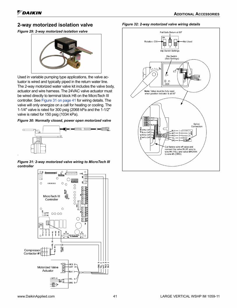
additional aCCessories
www.DaikinApplied.com 41 LARGE VERTICAL WSHP IM 1059-11
2-way motorized isolation valveFigure 29: 2-way motorized isolation valve
Used in variable pumping type applications, the valve ac-tuator is wired and typically piped in the return water line. The 2-way motorized water valve kit includes the valve body, actuator and wire harness. The 24VAC valve actuator must be wired directly to terminal block H8 on the MicroTech III controller. See Figure 31 on page 41 for wiring details. The valve will only energize on a call for heating or cooling. The 1-1/4" valve is rated for 300 psig (2068 kPa and the 1-1/2" valve is rated for 150 psig (1034 kPa).Figure 30: Normally closed, power open motorized valve
.
Figure 31: 2-way motorized valve wiring to MicroTech III controller
Figure 32: 2-way motorized valve wiring details

troubleshooting
MicroTech III unit controller and I/O expansion module status LED's and fault outputsTable 13: MicroTech III controller status LED's & fault outputs
Description Type* Yellow Green Red
I/O Expansion Communication Fail Fault ON Flash Flash
Invalid Configuration Fault Flash Flash OFF
Low Voltage Brownout Fault OFF Flash OFF
Emergency Shutdown Mode OFF Flash OFF
Compressor #1 High Pressure (HP1) Fault OFF OFF Flash
Compressor #1 Low Pressure (LP1) Fault OFF OFF ON
Compressor #1 Suction Temp Sensor Fail Fault Flash Flash ON
Freeze Fault Detect (Freeze Fault Protection Only) Fault Flash OFF Flash
Compressor #1 Low Suction Temp (LT1) Fault Flash OFF OFF
Room Temp Sensor Fail (with Room Sensor Control Only) Fault Flash Flash ON
Leaving Water Temp Sensor Fail (Freeze Fault Protection Only) Fault Flash Flash ON
Condensate Overflow (Cooling & Dehumidification Modes Only) Fault ON OFF OFF
Serial EEPROM Corrupted Fault ON ON ON
Service Test Mode Enabled Mode Flash Flash Flash
Unoccupied Mode Mode ON ON OFF
Occupied, Bypass, Standby, or Tenant Override Modes Mode OFF ON OFF
Note: * The MicroTech III baseboard LED's mode / faults are listed in order of priority.
Table 14: I/O expansion module status LED's & fault outputsDescription Type Yellow Green Red
Baseboard Communication Fail Fault OFF Flash Flash
Compressor #2 High Pressure (HP2) Fault OFF OFF Flash
Compressor #2 Low Pressure (LP2) Fault OFF OFF ON
Compressor #2 Low Suction Temp (LT2) Sensor Fail Fault Flash Flash ON
Compressor #2 Low Suction Temp (LT2) Fault Flash OFF OFF
Entering Water Temp Sensor Fail (with Boilerless Electric Heat and Waterside Economizer) Fault ON OFF Flash
Low Entering Water Temperature (No Display with Boilerless Electric Heat) Fault OFF ON Flash
Fan is OFF Mode OFF ON OFF
Fan is ON Mode OFF Flash OFF
Note: Mode / Faults are listed in order of priority.
IM 1059-11 LARGE VERTICAL WSHP 42 www.DaikinApplied.com

troubleshooting
MicroTech III unit controller LED faults and remedyTable 15: I/O expansion communication fail
Description Type Yellow Green Red
I/O Expansion Communication Fail Fault ON Flash Flash
• Verify connection of 12 wire cable between H5 on the main board and H1 on the I/O expansion board is fully engaged in the connector.
• Verify run program jumper on the I/O expansion board is installed in the run position.
• Replace the run jumper with a spare jumper.
• Replace I/O expansion board.
Table 16: Invalid configurationDescription Type Yellow Green Red
Invalid Configuration Fault Flash Flash OFF
• Verify jumper selection on both the main board and I/O expansion board. Jumper selections must be verified using the jumper configuration set-ting outline in this manual.
Table 17: Low voltage brownout / emergency shutdownDescription* Type Yellow Green Red
Low Voltage Brownout Fault OFF Flash OFF
Emergency Shutdown Mode OFF Flash OFF
* Same LED display for both conditions
• Verify the E terminal is not connected to common. Remove wire, if connected, and LED should change to solid green only.
• Confirm the low voltage supply is between 19-32VAC at the H1 terminal of the main board. If the low voltage supply is out of range, verify the unit supply voltage matches the nameplate voltage and the correct transformer primary wire has been selected.
Table 18: Compressor high pressureDescription Type Yellow Green Red
Compressor High Pressure Fault OFF OFF Flash
• Verify high pressure switch is connected to terminal H3 on the main board.
• Check for continuity of the high pressure switch.
If the high pressure fault resets when power is recycled:
• Check water flow (cooling operation)
• Check airflow (heating operation)
• Entering water and air temperatures should be within the operating limits.
Table 19: Compressor low pressureDescription Type Yellow Green Red
Compressor Low Pressure Fault OFF OFF ON
• Loose wire connection on low pressure circuit
• Failed low pressure switch
• Unit is low on charge
Table 20: Compressor suction temp sensor fail, room temp sensor fail, leaving water temp sensor failDescription Type Yellow Green Red
Compressor Suction Temp Sensor Fail Fault Flash Flash ON
Room Temp Sensor Fail (Room Sen-sor Control Only) Fault Flash Flash ON
Leaving Water Temp Sensor Fail Fault Flash Flash ON
• Check connection of low suction temperature sensor on terminal H6 pins 2 and 3.
• Check resistance of low suction temperature sensor, leaving water temperature sensor, and room sensor or return air sensor. All sensors are 10kohm thermistor @77°F.
• Return air sensor and room sensor shall not be connected simultaneously.
www.DaikinApplied.com 43 LARGE VERTICAL WSHP IM 1059-11

troubleshooting
Table 21: Compressor low suction tempDescription Type Yellow Green Red
Compressor Low Suction Temp Fault Flash OFF OFF
• Check water flow (heating operation)
• Check airflow (cooling operation)
• Entering water and air temperatures should be within the operating limits.
Table 22: Freeze fault detectDescription Type Yellow Green Red
Freeze Fault Detect Fault Flash OFF Flash
• Low entering water temperature (below 35°F standard range or 13.5°F extended range)
Table 23: Condensate overflowDescription Type Yellow Green Red
Condensate Overflow Fault ON OFF OFF
• Poor condensate drain
• Check the resistance to ground on condensate wire. This should be open if there is no water in the pan.
Table 24: Serial EEPROM corruptedDescription Type Yellow Green Red
Serial EEPROM Corrupted Fault ON ON ON
• Replace main board
Table 25: Waterside economizer low temp cutout (WSE control & call for cooling)Description Type Yellow Green Red
Waterside Economizer Low Temp Cutout (WSE Control & Call for
Cooling)Mode Flash ON Flash
• Water temperature is below 35°F.
Table 26: Service test mode enabledDescription Type Yellow Green Red
Service Test Mode Enabled Mode Flash Flash Flash
• Jumper JP1 is shorted for test mode operation.
Table 27: Unoccupied modeDescription Type Yellow Green Red
Unoccupied Mode Mode ON ON OFF
• Terminal U on main control board is connected to common from external source.
Table 28: Occupied, bypass, standby, or tenant override modesDescription Type Yellow Green Red
Occupied, Bypass, Standby, or Ten-ant Override Modes Mode OFF ON OFF
• Unit is operating normal. It may currently have a control signal or ready to operate when a control signal is active.
IM 1059-11 LARGE VERTICAL WSHP 44 www.DaikinApplied.com

www.DaikinApplied.com 45 LARGE VERTICAL WSHP IM 1059-11
troubleshooting
I/O expansion module LED faults and remedyTable 29: Baseboard communication fail
Description Type Yellow Green Red
Baseboard Communication Fail Fault Flash OFF Flash
• Verify jumper JP8 on main board is shorted.
• Verify connection of cable between H5 on main board and H1 on I/O expansion board.
Table 30: Compressor #2 high pressureDescription Type Yellow Green Red
Compressor #2 High Pressure Fault OFF OFF Flash
• Verify high pressure switch is connected to terminal HP2 on the I/O expansion.
• Check for continuity of the high pressure switch.
If the high pressure fault resets when power is recycled:
• Check water flow (cooling operation)
• Check airflow (heating operation)
• Entering water and air temperatures should be within the operating limits
Table 31: Compressor #2 low pressureDescription Type Yellow Green Red
Compressor #2 Low Pressure Fault OFF OFF ON
• Loose wire connection on low pressure circuit
• Failed low pressure switch
• Circuit #2 is low on charge
Table 32: Compressor #2 low suction tempDescription Type Yellow Green Red
Compressor #2 Low Suction Temp Fault Flash OFF OFF
• Check water flow (heating operation)
• Check airflow (cooling operation)
• Entering water and air temperatures should be within the operating limits.
Table 33: Compressor #2 low suction tempDescription Type Yellow Green Red
Compressor #2 Low Suction Temp Fault Flash OFF OFF
• Check water flow (heating operation)
• Check airflow (cooling operation)
• Entering water and air temperatures should be within the operating limits.
Table 34: Compressor suction temp sensor failDescription Type Yellow Green Red
Compressor Suction Temp Sensor Fail Fault Flash OFF OFF
• Check connection of low suction temperature sensor on terminal H7 pins 1 and 2.
• Check resistance of low suction temperature sensor. All sensors are 10kohm thermistor @77°F.
Table 35: Entering water temp sensor fail (boilerless electric heat or waterside economizer only)Description Type Yellow Green Red
Entering Water Temp Sensor Fail (Boilerless Electric Heat or Waterside
Economizer Only)Fault ON OFF Flash
• Verify connections at terminals H4 on the I/O expansion board
• Verify resistance of EWT thermistor is 10K @ 77°F.
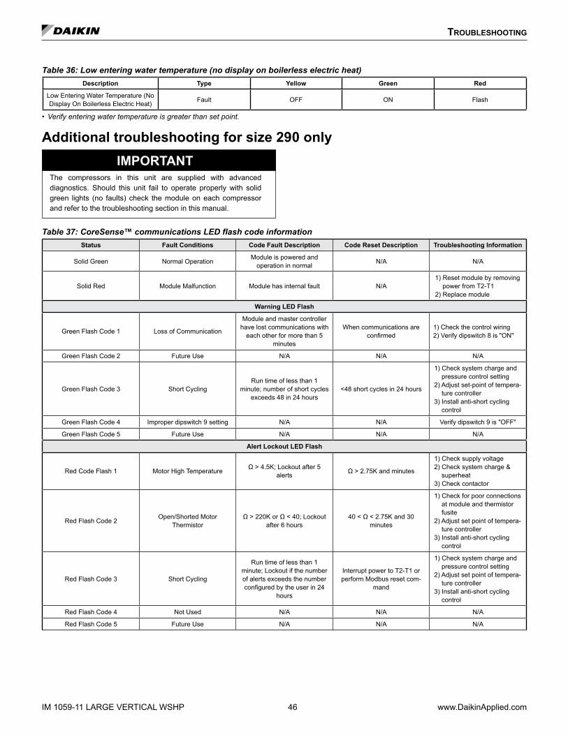
IM 1059-11 LARGE VERTICAL WSHP 46 www.DaikinApplied.com
troubleshooting
Table 36: Low entering water temperature (no display on boilerless electric heat)Description Type Yellow Green Red
Low Entering Water Temperature (No Display On Boilerless Electric Heat) Fault OFF ON Flash
• Verify entering water temperature is greater than set point.
Additional troubleshooting for size 290 onlyIMPORTANT
The compressors in this unit are supplied with advanced diagnostics. Should this unit fail to operate properly with solid green lights (no faults) check the module on each compressor and refer to the troubleshooting section in this manual.
Table 37: CoreSense™ communications LED flash code informationStatus Fault Conditions Code Fault Description Code Reset Description Troubleshooting Information
Solid Green Normal Operation Module is powered and operation in normal N/A N/A
Solid Red Module Malfunction Module has internal fault N/A1) Reset module by removing
power from T2-T12) Replace module
Warning LED Flash
Green Flash Code 1 Loss of Communication
Module and master controller have lost communications with
each other for more than 5 minutes
When communications are confirmed
1) Check the control wiring2) Verify dipswitch 8 is "ON"
Green Flash Code 2 Future Use N/A N/A N/A
Green Flash Code 3 Short CyclingRun time of less than 1
minute; number of short cycles exceeds 48 in 24 hours
<48 short cycles in 24 hours
1) Check system charge and pressure control setting
2) Adjust set-point of tempera-ture controller
3) Install anti-short cycling control
Green Flash Code 4 Improper dipswitch 9 setting N/A N/A Verify dipswitch 9 is "OFF"
Green Flash Code 5 Future Use N/A N/A N/A
Alert Lockout LED Flash
Red Code Flash 1 Motor High Temperature Ω > 4.5K; Lockout after 5 alerts Ω > 2.75K and minutes
1) Check supply voltage2) Check system charge &
superheat3) Check contactor
Red Flash Code 2 Open/Shorted Motor Thermistor
Ω > 220K or Ω < 40; Lockout after 6 hours
40 < Ω < 2.75K and 30 minutes
1) Check for poor connections at module and thermistor fusite
2) Adjust set point of tempera-ture controller
3) Install anti-short cycling control
Red Flash Code 3 Short Cycling
Run time of less than 1 minute; Lockout if the number of alerts exceeds the number configured by the user in 24
hours
Interrupt power to T2-T1 or perform Modbus reset com-
mand
1) Check system charge and pressure control setting
2) Adjust set point of tempera-ture controller
3) Install anti-short cycling control
Red Flash Code 4 Not Used N/A N/A N/A
Red Flash Code 5 Future Use N/A N/A N/A

www.DaikinApplied.com 47 LARGE VERTICAL WSHP IM 1059-11
Red Flash Code 6 Missing phase Missing phase; Lockout after 10 consecutive alerts
After 5 minutes and missing phase condition is not present
1) Check incoming power2) Check fuses/breakers3) Check contactor
Red Flash Code 7 Reverse phase Reverse phase; Lockout after 1 alert
Interrupt power to T2-T1 or perform Modbus reset com-
mand
1) Check incoming phase sequence
2) Check contactor3) Check module phasing
wires A-B-C
Red Flash Code 8 Future Use N/A N/A N/A
Red Flash Code 9 Module Low Voltage Low voltage on T2-T1 terminals*
After 5 minutes and the voltage is back in the normal
range
1) Verify correct module p/n2) Check VA rating of trans-
former3) Check for blown fuse in
transformer secondary
Notes: The flash code number corresponds to the number of LED flashes, followed by a pause, and then the flash code is repeated. A lockout condition produces a red flash, followed by a pause, a solid red, a second pause, and then repeated.
* This alert does not result in a Lockout
Troubleshooting water source heat pump unitsTable 38: Troubleshooting refrigeration circuit
SymptomHead
PressureSuction
PressureCompressor Amp Draw Super Heat Subcooling Air Temp
DifferentialWater (loops)
Temp DifferentialSafety
Lock Out
Charge Undercharge System (Possible Leak) Low Low Low High Low Low Low Low Pressure
Overcharge System High High High Normal HighNormal
Normal High PressureLow
Low Air Flow Heating High High HighHigh
Low High Low High PressureNormal
Low Air Flow Cooling Low Low LowLow
High High Low Low TempNormal
Low Water Flow HeatingLow Low
Low Low High Low High Low TempNormal Normal
Low Water Flow Cooling High High High High Low Low High High Pressure
High Air Flow Heating Low Low Low Low High Low Low Low Temp
High Air Flow Cooling Low High Normal High Low Low Normal High Pressure
High Water Flow Heating Normal Low Normal High Normal Normal Low High Pressure
High Water Flow Cooling Low Low Low Low High Normal Low Low Temp
TXV Restricted High LowNormal
High High Low LowLow
troubleshooting
CoreSense communications LED flash code information (continued)
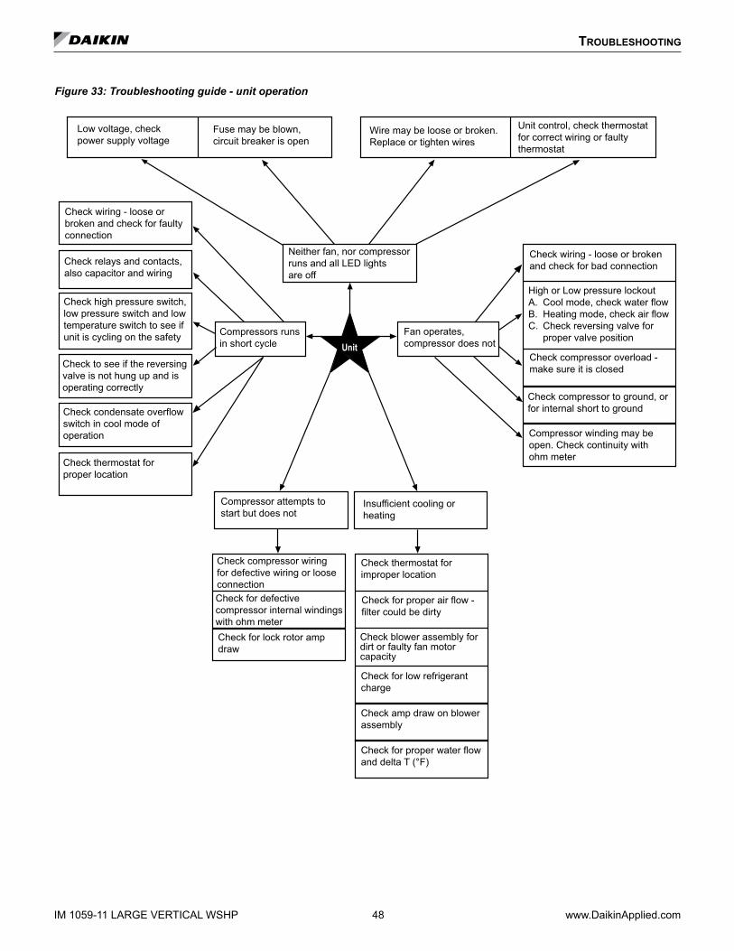
IM 1059-11 LARGE VERTICAL WSHP 48 www.DaikinApplied.com
troubleshooting
Figure 33: Troubleshooting guide - unit operation
Unit
Low voltage, check power supply voltage
Fuse may be blown, circuit breaker is open
Wire may be loose or broken. Replace or tighten wires
Unit control, check thermostat for correct wiring or faulty thermostat
Check wiring - loose or broken and check for faulty connection
Check relays and contacts, also capacitor and wiring
Check high pressure switch, low pressure switch and low temperature switch to see if unit is cycling on the safety
Check to see if the reversing valve is not hung up and is operating correctly
Check condensate overflow switch in cool mode of operation
Compressor attempts to start but does not
Check compressor wiring for defective wiring or loose connection
Insufficient cooling or heating
Check for lock rotor amp draw
Check for defective compressor internal windings with ohm meter
Check for proper air flow - filter could be dirty
Check for low refrigerant charge
Check amp draw on blower assembly
Fan operates, compressor does not
Compressors runs in short cycle
Neither fan, nor compressor runs and all LED lights are off
Check wiring - loose or broken and check for bad connection
High or Low pressure lockout A. Cool mode, check water flowB. Heating mode, check air flowC. Check reversing valve for
proper valve position
Check compressor overload - make sure it is closed
Check compressor to ground, or for internal short to ground
Compressor winding may be open. Check continuity with ohm meter
Check thermostat for improper location
Check blower assembly fordirt or faulty fan motor capacity
Check thermostat forproper location
Check for proper water flowand delta T (°F)

www.DaikinApplied.com 49 LARGE VERTICAL WSHP IM 1059-11
LubricationR-410A should be used only with polyester (POE) oil. The HFC refrigerant components in R-410A will not be compatible with mineral oil or alkylbenzene lubricants. R-410A systems will be charged with the OEM recommended lubricant, ready for use with R-410A.
ChargingDue to the zeotropic nature of R- 410A, it should be charged as a liquid. In situations where vapor is normally charged into a system, a valve should be installed in the charging line to flash the liquid to vapor while charging. Make certain that the recycle or recovery equipment used is designed for R-410A. The pressure of R-410A refrigerant is approximately 60 percent greater than that of R-22. Pressure gauges require a range up to 800 PSIG high side and 250 PSIG low side. Recovery cylinders require a 400 PSIG rating – do not put R-410A in a 300 PSIG rated cylinder.
WARNINGRecycle/recovery equipment must be designated for R-410A. R-410A pressure is greater than R-22. Improper equipment can cause severe injury or death.
Note: Because a water source heat pump operates under a wide range of water and air tempera-tures, the values printed below are to be taken as suggested pressure and temperatures.) All Daikin water source heat pumps are designed for commercial use. The units are designed for the cooling mode of operation and fail safe to cooling. The reversing valve is energized for the heating mode of operation.
Superheat Head Pressure Water Delta T 8 to 14 degrees 335-355 PSIG 10° to 14°
Note: All information above is based on ISO standard 13256-1 and tested at these conditions.
General maintenance1 . Normal maintenance on all units is generally
limited to filter changes. Units are provided with permanently lubricated motors and require no oiling even though oil caps may be provided.
2 . Filter changes are required at regular intervals. The time period between changes will depend upon the project requirements. Some applications such as motels produce a lot of lint from carpeting and linen changes, and will require more frequent filter changes. Check filters at 60-day intervals for the first year until experience is acquired. If light cannot be seen through the filter when held up to sunlight or a bright light, it should be changed. A more critical standard may be desirable.
3 . The condensate drain pan should be checked annually and cleaned and flushed as required.
4 . Record performance measurements of volts, amps, and water temperature differences (both heating and cooling). A comparison of logged data with start-up and other annual data is useful as an indicator of general equipment condition.
5 . Periodic lockouts almost always are caused by air or water problems. The lockout (shutdown) of the unit is a normal protective result. Check for dirt in the water system, water flow rates, water temperatures, airflow rates (may be a dirty filter), and air temperatures. If the lockout occurs in the morning following a return from night setback, entering air below machine limits may be the cause.
general MaintenanCe

IM 1059-11 LARGE VERTICAL WSHP 50 www.DaikinApplied.com
Typical cooling refrigeration cycle – dual compressorsNote: Typical temperature readings are at full load con-
ditions at ISO-13256 for boiler-tower applications.When the wall thermostat calls for COOLING, the reversing valve (de-energized) directs the flow of the refrigerant, a hot gas, from the compressor to the water-to-refrigerant heat exchanger (coaxial heat exchanger). There, the heat is removed by the water, and the hot
gas condenses to become a liquid. The liquid then flows through a thermal expansion valve to the air-to-refrigerant heat exchanger coil (evaporator). The liquid then evaporates and becomes a gas, at the same time absorbing heat and cooling the air passing over the surfaces of the coil. The refrigerant then flows as a low pressure gas through the reversing valve and back to the suction side of the compressor to complete the cycle. Figure 34: Cooling refrigeration cycle
tyPiCal refrigeration CyCles

www.DaikinApplied.com 51 LARGE VERTICAL WSHP IM 1059-11
Typical heating refrigeration cycle – dual compressorsNote: Typical temperature readings are at full load con-
ditions at ISO-13256 for boiler-tower applications.When the wall thermostat calls for HEATING, the reversing valve (energized) directs the flow of the refrigerant, a hot gas, from the compressor to the air-to-refrigerant heat exchanger coil (condenser). There,
the heat is removed by the air passing over the surfaces of the coil and the hot gas condenses and becomes a liquid. The liquid then flows through a thermal expansion valve to the water-to-refrigerant heat exchanger (evaporator). The liquid then evaporates and becomes a gas, at the same time absorbing heat and cooling the water. The refrigerant then flows as a low pressure gas through the reversing valve and back to the suction side of the compressor to complete the cycle.
tyPiCal refrigeration CyCles
Figure 35: Heating Refrigeration Cycle
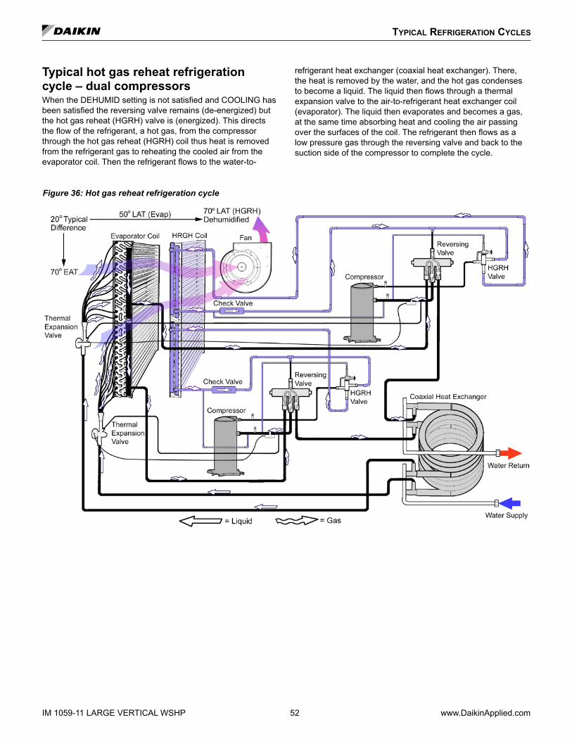
IM 1059-11 LARGE VERTICAL WSHP 52 www.DaikinApplied.com
Typical hot gas reheat refrigeration cycle – dual compressorsWhen the DEHUMID setting is not satisfied and COOLING has been satisfied the reversing valve remains (de-energized) but the hot gas reheat (HGRH) valve is (energized). This directs the flow of the refrigerant, a hot gas, from the compressor through the hot gas reheat (HGRH) coil thus heat is removed from the refrigerant gas to reheating the cooled air from the evaporator coil. Then the refrigerant flows to the water-to-
refrigerant heat exchanger (coaxial heat exchanger). There, the heat is removed by the water, and the hot gas condenses to become a liquid. The liquid then flows through a thermal expansion valve to the air-to-refrigerant heat exchanger coil (evaporator). The liquid then evaporates and becomes a gas, at the same time absorbing heat and cooling the air passing over the surfaces of the coil. The refrigerant then flows as a low pressure gas through the reversing valve and back to the suction side of the compressor to complete the cycle.
tyPiCal refrigeration CyCles
Figure 36: Hot gas reheat refrigeration cycle

www.DaikinApplied.com 53 LARGE VERTICAL WSHP IM 1059-11
Job Name _________________________________________________________ Check, Test & Start Date ________________
City or Town __________________________________________ State _________________________ Zip ________________
Who is Performing CTS _____________________________________ Equipment Type (Check all that apply)
General Contractor _________________________________________
Essential Items Check of System – Note: “No” answers below require notice to installer by memorandum (attached copy.)
Closed Loop Open Loop
Geothermal Other (specify)______________
Water source heat pump equipment check, test and start form
Essential Items Check
A. Voltage Check __________ Volts Loop Temp. ___________ °F Heating System Water P.H. Levels __________ Set For ___________ °F Cooling
B. Yes No Condition Comments
Loop Water Flushed Clean _________________________________________________________________
Closed Type Cooling Tower _________________________________________________________________
Water Flow Rate to Heat Pump Balanced ______________________________________________________
Standby Pump Installed ___________________________________________________________________
System Controls Functioning _______________________________________________________________
Outdoor Portion of Water System Freeze Protected ______________________________________________
Loop System Free of Air ___________________________________________________________________
Filters Clean ____________________________________________________________________________
Condensate Traps Installed _________________________________________________________________
Note: “No” answers below require notice to installer by memorandum (attached copy.)
Outdoor Air to Heat Pumps: ________________________________________________________________
Other Conditions Found: ___________________________________________________________________
This form must be completed and submitted within ten (10) days of start-up to comply with the terms of the Daikin warranty. Forms should be returned to Daikin Warranty Department.
Installation Data
Please include any suggestions or comments for Daikin Applied: ___________________________________________________
______________________________________________________________________________________________________
______________________________________________________________________________________________________
______________________________________________________________________________________________________
Above System is in Proper Working OrderNote: This form must be filled out and sent to the warranty administrator before any service money can be released.
Date
Signature for Sales Representative
Signature for Customer
For Internal Use Release:
SM ________________________
CTS ________________________
T ________________________
Service Manager Approval
Date

IM 1059-11 LARGE VERTICAL WSHP 54 www.DaikinApplied.com
Unit check / equipment dataInstallation Data
Job Name ___________________________________________________ Check Test Date: __________________________
City __________________________________________________________ State _______________ Zip ______________
Daikin Model # ______________________________________________________
Daikin Serial # _______________________________________ Job site Unit ID # (HP #) _____________________________
General Contractor: _____________________________________ Mechanical Contractor: _____________________________
Technician Performing Start-Up: Name ______________________________ Employer: _____________________________
Complete equipment data from measurements taken at the locations indicated on the drawing below .
Equipment Data
Flow Rate EWP - LWP = ∆P
EWP - PSI In _________________minus LWP - PSI Out __________ equals ∆P ____________
The first step in finding GPM is to subtract leaving water pressure from entering water pressure. The difference between the two is referred to as ∆P. ∆P can be converted to GPM by looking in the equipment specificaton catalog. Caution ∆P ≠ GPM
Note: A conversion table must be used to find GPM from (Delta) ∆P measurements.
Loop Fluid Temperature Rise / Drop through Coaxial Heat Exchanger EWT - LWT = ∆T
EWT - °F Out _________________ minus LWT - °F Out __________________ equals Fluid ∆T _______________
∆T is the rise or drop in the fluid temperature as it passes through the Coaxial.
Air Temperature Rise / Drop through the air coil ∆T x CFM x 1.08 = BTUH Sensible
EAT - °F In ___________________ minus LAT - °F Out ___________________ equals Air ∆T _________________
Note: Perform Check, Test and Start-Up in the Cooling Mode Only .
EWT - Entering Water Temperature EWP - Entering Water Pressure EAT - Entering Air Temperature ∆ - Delta (Differential)
LWT - Leaving Water Temperature LWP - Leaving Water Pressure LAT - Leaving Air Temperature CFM - Cubic Feet/Minute
BTUH - British Thermal Units/Hour
AIR
COIL
V
VV
V
V
V
DischargeHot Gas
Suction
Compressor
Reversing Valve
V
COAX
IN OUTLWP
LWT
Loop Fluid Pressure (In PSI) EWP
Loop Fluid Temperature °F EWT
EATAir Temperature °F
LAT
IN OUT
ExpansionValve
Check, Test & Start
13
24
5 6
1 2
3 4
5 6
Form No . ____________________________

www.DaikinApplied.com 55 LARGE VERTICAL WSHP IM 1059-11
Commercial check, test and start worksheet(Complete all equipment measurements indicated for each unit per installation on previous page)
Model Serial # H .P . # EWT 3
LWT 4
EWP 1
LWP 2
EAT 5
LAT 6 Volts
Amps Cool-ing
Check Air
Filter and Coil
Comments(provide comments on
additional sheets)
1.
2.
3.
4.
5.
6.
7.
8.
9.
10.
11.
12.
13.
14.
15.
16.
17.
18.
19.
20.
21.
22.
23.
24.
25.
26.
27.
28.
29.
30.
31.
32.
33.
34.
35.
36.
37.
38.
39.
40.
41.
42.
Part No . _____________________________

IM 1059-11 ©2018 Daikin Applied (01/18) | (800) 432–1342 | www.DaikinApplied.com
Daikin Applied Training and Development
Now that you have made an investment in modern, efficient Daikin equipment, its care should be a high priority. For training information on all Daikin HVAC products, please visit us at www.DaikinApplied.com and click on Training, or call 540-248-9646 and ask for the Training Department.
Warranty
All Daikin equipment is sold pursuant to its standard terms and conditions of sale, including Limited Product Warranty. Consult your local Daikin Applied representative for warranty details. Refer to Form 933-430285Y. To find your local Daikin Applied representative, go to www.DaikinApplied.com.
Aftermarket Services
To find your local parts office, visit www.DaikinApplied.com or call 800-37PARTS (800-377-2787). To find your local service office, visit www.DaikinApplied.com or call 800-432-1342.
This document contains the most current product information as of this printing. For the most up-to-date product information, please go to www.DaikinApplied.com.
Products manufactured in an ISO Certified Facility.


![+RUL]RQWDO&HLOLQJ 0RXQWHG :DWHU6RXUFH ......CAT 1108-29 • ENFINITY HORIZONTAL WSHP 2 Contents Model Nomenclature . . . . . . . . . . . . . . . . . . . . . . . . .3 . AHRI Performance](https://img.dokumen.tips/doc/110x75/6103972cec713301f26eae5c/rulrqwdohlolqj-0rxqwhg-dwhu6rxufh-cat-1108-29-a-enfinity-horizontal.jpg)


![+RUL]RQWDO :DWHU6RXUFH+HDW3XPSV · Installation and Maintenance Manual IM 1060-9 Group: WSHP Part Number: 910301787 Date: January 2020 (Q¿QLW\ /DUJH&DSDFLW\+RUL]RQWDO :DWHU6RXUFH+HDW3XPSV](https://img.dokumen.tips/doc/110x75/5f841b963fb16612484d2a75/rulrqwdo-dwhu6rxufhhdw3xpsv-installation-and-maintenance-manual-im-1060-9-group.jpg)


![+RUL]RQWDO&HLOLQJ 0RXQWHG :DWHU6RXUFH+HDW3XPSV · K = 460/60/3* L = 575/60/3 M = 230/50/1 N = 380/50/3 Return Air 08 12 L = Left R = Right Discharge Air 09 13 E = End Discharge S](https://img.dokumen.tips/doc/110x75/5e976e74c28c933f304e5f06/rulrqwdohlolqj-0rxqwhg-dwhu6rxufhhdw3xpsv-k-460603-l-575603-m.jpg)