Embed Size (px)
Citation preview

OM-G102A
HYDRAULICS INTERNATIONAL, INC.
OPERATION AND MAINTENANCE INSTRUCTIONS
FOR
AIR DRIVEN GAS BOOSTER DOUBLE ACTING, DOUBLE AIR DRIVE
AS CHECKED BELOW:
OM-GDD-100 (7 Pages) APPLIES TO ALL MODELS BELOW: SPECIFIC
Drawings MODEL Trouble- shooting Unit Sub-assy Seal Kits
80832 80217 80627 80219 80628 80287 80289
5G-DD-14 5G-DD-14 5 Pages
80279 80209 80627 80212 80629 80217 80219
5G-DD-28 5G-DD-28 5 Pages
80280 80210 80627 80213 80630 80217 80219
5G-DD-60 5G-DD-60 5 Pages
80963 80217 80627 80219 80636 80969 80976
5G-DD-100 5G-DD-100 5 Pages
80281 80211 80627 80214 80631 80217 80219
5G-DD-150 5G-DD-150 5 Pages
Supplementary Data Attached:

OM-GDD100A
CONTENTS A. GENERAL INSTRUCTIONS – OM-GDD-100
1.0 SAFETY INFORMATION
1.1 High Pressure Gas 1.1.1 Mishandling 1.1.2 Misapplication 1.1.2.1 Published Ratings 1.1.2.2 Potential Pressures 1.1.2.3 Basic Data Maximum Safe Pressures By Model 1.1.2.4 Basic Formulas Potential Outlet Pressures 1.1.2.5 Compression Ratio Limits – Chart 1
2.0 LIMITED WARRANTY – RETURN GOODS AUTHORIZATION (RGA)
3.0 ASSEMBLY DRAWINGS AND PARTS LISTS
3.1 Unit Assembly 3.2 Subassembly Detail 3.3 Seal Kit Assembly Detail
4.0 PORT CONFIGURATION DETAIL
5.0 THEORY OF OPERATION
5.1 Drive Section 5.2 Boost Section 5.3 Cycling Section 5.4 Operational and Area Relationships
6.0 STARTUP/SHUTDOWN
6.1 Controls 6.2 Operation
7.0 MAINTENANCE
7.1 Periodic 7.2 Special Tools
B. SPECIFIC ATTACHMENTS BY MODEL 8.0 TROUBLESHOOTING BY SPECIFIC MODEL
8.1 Understanding How It Works 8.2 The Basic Drive System 8.3 The Basic Gas Boosting System 8.4 The Basic Air Cycling System 8.5 Chart: Symptoms and Suggested Remedies
9.0 TESTING 9.1 Individual Gas Sections 9.2 Both Gas Sections in Parallel 9.3 Drive Section
1 of 7
OM-GDD100A
A. GENERAL INSTRUCTIONS
1.0 SAFETY INFORMATION
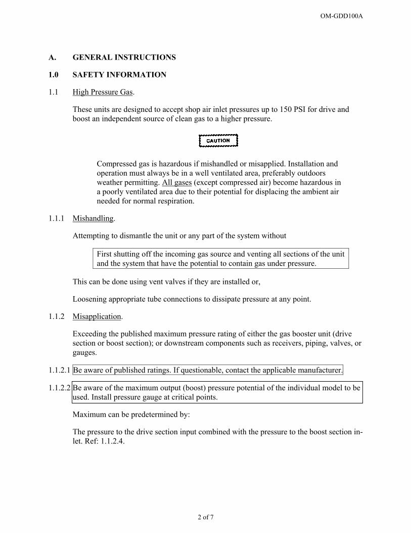
1.1 High Pressure Gas.
These units are designed to accept shop air inlet pressures up to 150 PSI for drive and boost an independent source of clean gas to a higher pressure.
Compressed gas is hazardous if mishandled or misapplied. Installation and operation must always be in a well ventilated area, preferably outdoors weather permitting. All gases (except compressed air) become hazardous in a poorly ventilated area due to their potential for displacing the ambient air needed for normal respiration.
1.1.1 Mishandling.
Attempting to dismantle the unit or any part of the system without
First shutting off the incoming gas source and venting all sections of the unit and the system that have the potential to contain gas under pressure.
This can be done using vent valves if they are installed or,
Loosening appropriate tube connections to dissipate pressure at any point.
1.1.2 Misapplication.
Exceeding the published maximum pressure rating of either the gas booster unit (drive section or boost section); or downstream components such as receivers, piping, valves, or gauges.
1.1.2.1 Be aware of published ratings. If questionable, contact the applicable manufacturer.
1.1.2.2 Be aware of the maximum output (boost) pressure potential of the individual model to be used. Install pressure gauge at critical points.
Maximum can be predetermined by:
The pressure to the drive section input combined with the pressure to the boost section in-let. Ref: 1.1.2.4.
2 of 7
OM-GDD100A
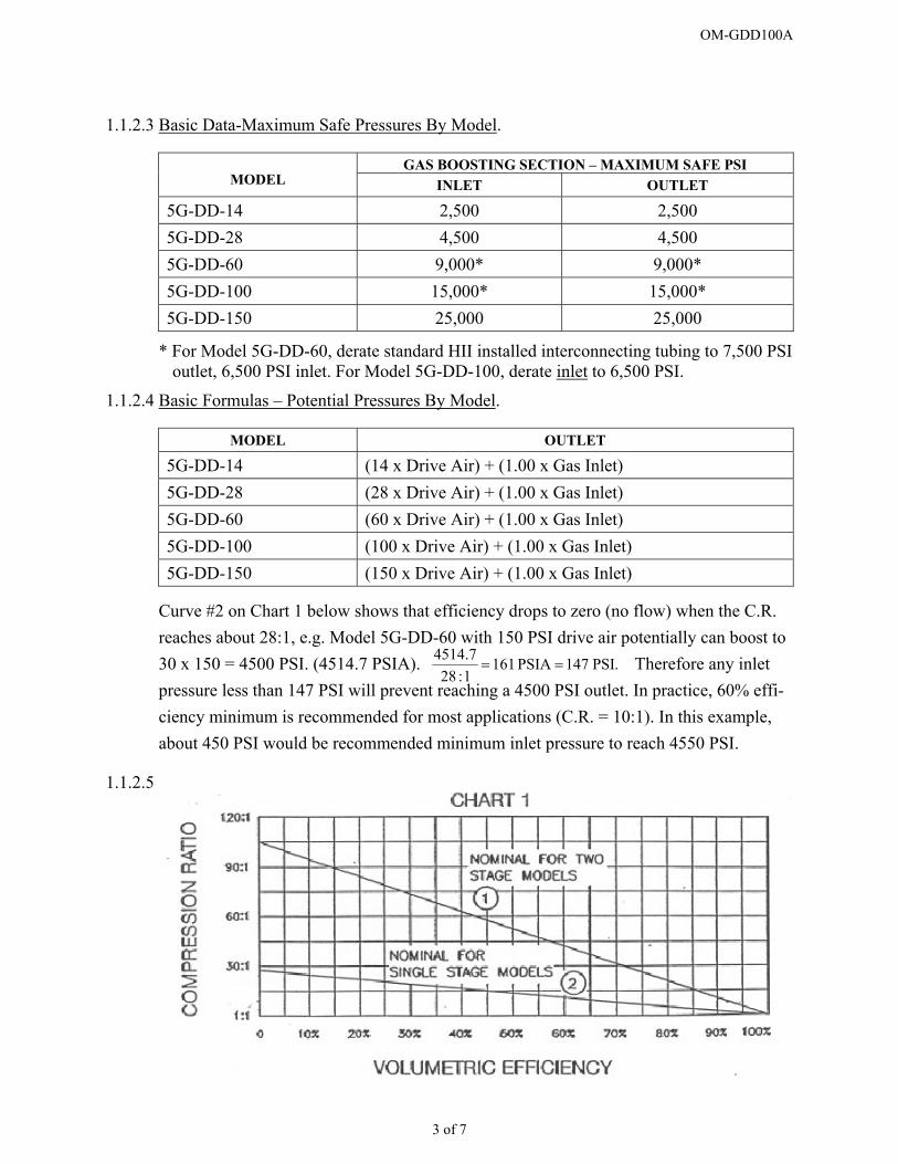
1.1.2.3 Basic Data-Maximum Safe Pressures By Model.
GAS BOOSTING SECTION – MAXIMUM SAFE PSI MODEL INLET OUTLET
5G-DD-14 2,500 2,500 5G-DD-28 4,500 4,500 5G-DD-60 9,000* 9,000* 5G-DD-100 15,000* 15,000* 5G-DD-150 25,000 25,000
* For Model 5G-DD-60, derate standard HII installed interconnecting tubing to 7,500 PSI outlet, 6,500 PSI inlet. For Model 5G-DD-100, derate inlet to 6,500 PSI.
1.1.2.4 Basic Formulas – Potential Pressures By Model.
MODEL OUTLET
5G-DD-14 (14 x Drive Air) + (1.00 x Gas Inlet) 5G-DD-28 (28 x Drive Air) + (1.00 x Gas Inlet) 5G-DD-60 (60 x Drive Air) + (1.00 x Gas Inlet) 5G-DD-100 (100 x Drive Air) + (1.00 x Gas Inlet) 5G-DD-150 (150 x Drive Air) + (1.00 x Gas Inlet)
Curve #2 on Chart 1 below shows that efficiency drops to zero (no flow) when the C.R. reaches about 28:1, e.g. Model 5G-DD-60 with 150 PSI drive air potentially can boost to 30 x 150 = 4500 PSI. (4514.7 PSIA). Therefore any inlet pressure less than 147 PSI will prevent reaching a 4500 PSI outlet. In practice, 60% effi-ciency minimum is recommended for most applications (C.R. = 10:1). In this example, about 450 PSI would be recommended minimum inlet pressure to reach 4550 PSI.
4514= .PSI147PSIA161
1:287.
=
1.1.2.5
3 of 7

OM-GDD100A
2.0 LIMITED WARRANTY
Hydraulics International manufactured products are warranted free of original defects in material and workmanship for a period of one year from date of purchase to first user. This warranty does not include O-rings, seals or failures caused by lack of proper main-tenance, incompatible fluids, foreign contaminants in the drive section, in the pump sec-tion or application of pressures beyond catalog ratings. Products believed to be originally defective may be returned, freight prepaid, for repair and/or replacement to the distributor or to the factory. If upon inspection by the factory or distributor the problem is found to be originally defective material or workmanship, repair or replacement will be made at no charge for labor or materials, F.O.B. the point of repair or replacement. Permission to re-turn under warrant should be requested before shipment and include the following: A Re-turn Goods Authorization Number (RGA), the original purchase date, purchase order number, serial number, model number, reason for return or other pertinent data to estab-lish warranty claim and to expedite the return or replacement to the owner.
If the unit has been disassembled and reassembled in a facility other than HYDRAULICS INTERNATIONAL without prior written authorization, warranty is void if it has been improperly reassembled or substitute parts have been used in place of factory manufac-tured parts.
Any modification to any HYDRAULICS INTERNATIONAL product that you have made or may make in the future has been and will be at your sole risk and responsibility, and without HYDRAULICS INTERNATIONAL’s approval or consent. HYDRAULICS INTERNATIONAL disclaims any and all liability obligation, or responsibility for the modified product. And for any claims, demands or causes of action for damage or for personal injuries resulting from the modification and/or use of such a modified HY-DRAULICS INTERNATIONAL product.
HYDRAULICS INTERNATIONAL obligation with respect to its products shall be limited to replacement, and in no event shall HYDRAULICS INTERNATIONAL be liable for any loss or damage, consequential or special, of whatever kind or nature, or any other expense which may arise in connection with or as a result of such products or the use or incorporation thereof in a job. This warranty is expressly made in lieu of all other warranties of merchantability and fitness for a particular purpose. No express warranty and no implies warranties whether of merchantabil-ity or fitness for a particular purpose or otherwise, other than those expressly set forth above, shall apply to HYDRAULICS INTERNATIONAL products.
4 of 7

OM-GDD100A
3.0 ASSEMBLY, PARTS LIST, AND SUBASSEMBLY DRAWINGS
The DRAWINGS that apply are listed on the front cover page, and are also attached.
3.1 Unit Assembly Drawing.
- Lists all parts in your unit by Item No. vs Part No.
- Lists any subassemblies by their own drawing number.
- Lists all seal kits by their own drawing number.
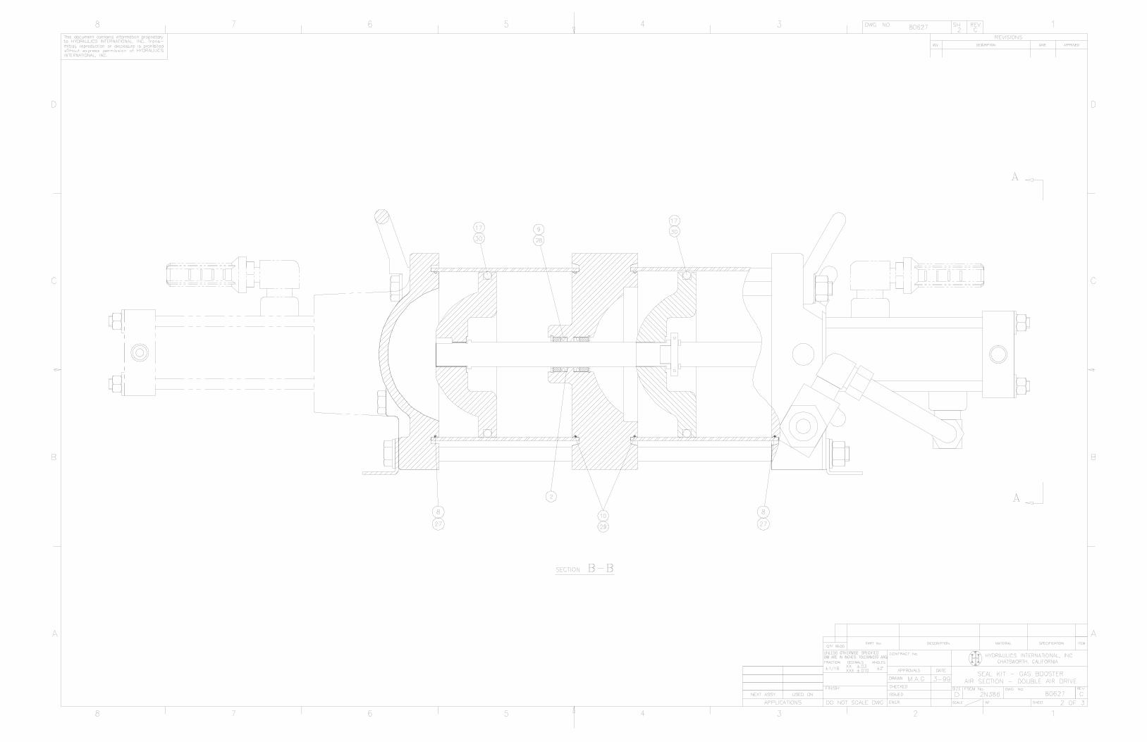
- Provides a detailed cross section of your unit which will be the major reference in a subsequent discussion of operation, maintenance, and troubleshooting.
3.2 Subassembly Drawings provide subassembly cross section detail plus piece part item numbers whose part numbers are listed on page 1 of the subassembly drawing.
3.3 Seal Kit Drawings provide cross section detail with item numbers showing where each seal kit item fits. Part numbers are listed on both the seal kit drawing and on the unit as-sembly drawing, but item numbering will differ.
4.0 PORT CONFIGURATION DETAIL Refer to current catalog GB500 under selection table and notes.
5.0 THEORY OF OPERATION All units consist of 3 basic sections, each with their specific function;
5.1 Drive Section.
Provides the reciprocating force to the boost section.
5.2 Boost Sections.
Provides the compressing (pumping) action for high pressure output.
5.3 Cycling Section.
Consists of the directional control air valving built into the drive enabling the drive to re-ciprocate continuously whenever air is applied to the drive input.
5.4 Operational and Area Relationships. PISTON AREA RATIOS-
NOMINAL MODEL
A:A1* A:A2* A1:A2 5G-DD-14 14:1 14:1 1:1 5G-DD-28 28:1 28:1 1:1 5G-DD-60 60:1 60:1 1:1 5G-DD-100 100:1 100:1 1:1 5G-DD-150 150:1 150:1 1:1
* Point of possible confusion: Note that on the attached Gas Section and End Cap Assembly Drawings, the “-Ratio” designation is ½ the above A:A1 and A:A2. Reason: These assemblies and drawings are all derived from the basic single air drive models, and when used with these double air drives, the basic area ”Ratio” doubles.
5 of 7
OM-GDD100A
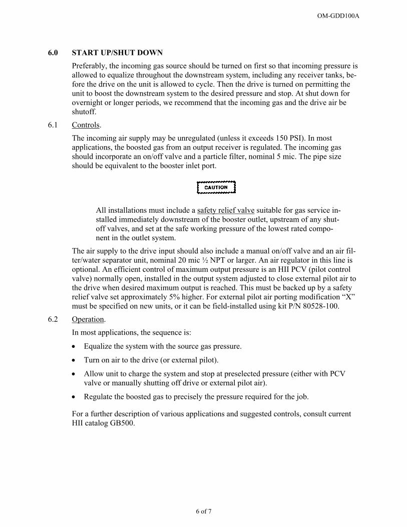
6.0 START UP/SHUT DOWN
Preferably, the incoming gas source should be turned on first so that incoming pressure is allowed to equalize throughout the downstream system, including any receiver tanks, be-fore the drive on the unit is allowed to cycle. Then the drive is turned on permitting the unit to boost the downstream system to the desired pressure and stop. At shut down for overnight or longer periods, we recommend that the incoming gas and the drive air be shutoff.
6.1 Controls.
The incoming air supply may be unregulated (unless it exceeds 150 PSI). In most applications, the boosted gas from an output receiver is regulated. The incoming gas should incorporate an on/off valve and a particle filter, nominal 5 mic. The pipe size should be equivalent to the booster inlet port.
All installations must include a safety relief valve suitable for gas service in-stalled immediately downstream of the booster outlet, upstream of any shut-off valves, and set at the safe working pressure of the lowest rated compo-nent in the outlet system.
The air supply to the drive input should also include a manual on/off valve and an air fil-ter/water separator unit, nominal 20 mic ½ NPT or larger. An air regulator in this line is optional. An efficient control of maximum output pressure is an HII PCV (pilot control valve) normally open, installed in the output system adjusted to close external pilot air to the drive when desired maximum output is reached. This must be backed up by a safety relief valve set approximately 5% higher. For external pilot air porting modification “X” must be specified on new units, or it can be field-installed using kit P/N 80528-100.
6.2 Operation.
In most applications, the sequence is:
• Equalize the system with the source gas pressure.
• Turn on air to the drive (or external pilot).
• Allow unit to charge the system and stop at preselected pressure (either with PCV valve or manually shutting off drive or external pilot air).
• Regulate the boosted gas to precisely the pressure required for the job.
For a further description of various applications and suggested controls, consult current HII catalog GB500.
6 of 7

OM-GDD100A
7 of 7
7.0 MAINTENANCE.
7.1 Periodic.
All HII models incorporate a spool-type directional control valve that is the heart of the cycling system for the drive. The standard valve depends on dynamic O-rings which are lubricated with light grease at original assembly. *Periodically, these valve O-rings should be wiped clean and regreased for reliable operation. The frequency will be deter-mined by many variables such as air moisture content, contamination, cycle rates, and overall duty cycle of individual applications. All HII units are designed so that this spool/O-ring assembly is easily accessible with simple hand tools without disassembling any other sections of the drive. The typical symptom indicating need for regreasing the O-rings is slow, erratic cycling. It is suggested that a note be made of the frequency of this slow down, so that it can be predicted, and then the O-rings cleaned and regreased at a convenient shut down to insure uninterrupted operation when the unit is needed.
The detailed assembly drawing attached clearly shows the cycling spool/O-ring assembly and its accessibility.
Be sure the incoming air is shut off before removing any parts.
Periodic lubrication of any OTHER PARTS of the unit is NOT REQUIRED nor recom-mended.
* If the booster is equipped with modification “N”, a lapped, match fit spool and sleeve assembly replaces the O-ring sealed spool and is further explained on service bulletin SB02-NMOD.
7.2 Special Tools. Available at low cost from HII Service Dept.
P/N 80273-100 - Sleeve Extractor. Used for pulling the valve sleeve 80028-1 (Item 1, Drawing 80217) out of end cap assembly 80217. This is done only if it is necessary to re-place the 4 each O-rings, Item 8 on the sleeve O.D., or the bumper, Item 7 behind the sleeve.
P/N 80844-100 - Spanner Wrench. Used for removal or installation of check valve re-tainer nuts 80248, 80247, Items 9 and 10 on the Gas Section End Cap Assembly Draw-ing.
5G-DD-14
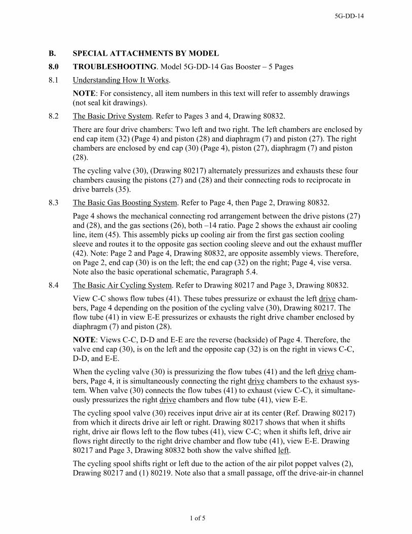
B. SPECIAL ATTACHMENTS BY MODEL
8.0 TROUBLESHOOTING. Model 5G-DD-14 Gas Booster – 5 Pages
8.1 Understanding How It Works.
NOTE: For consistency, all item numbers in this text will refer to assembly drawings (not seal kit drawings).
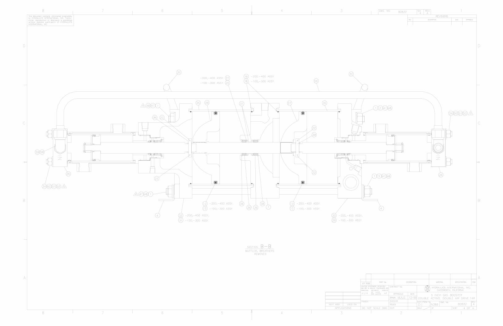
8.2 The Basic Drive System. Refer to Pages 3 and 4, Drawing 80832.
There are four drive chambers: Two left and two right. The left chambers are enclosed by end cap item (32) (Page 4) and piston (28) and diaphragm (7) and piston (27). The right chambers are enclosed by end cap (30) (Page 4), piston (27), diaphragm (7) and piston (28).
The cycling valve (30), (Drawing 80217) alternately pressurizes and exhausts these four chambers causing the pistons (27) and (28) and their connecting rods to reciprocate in drive barrels (35).
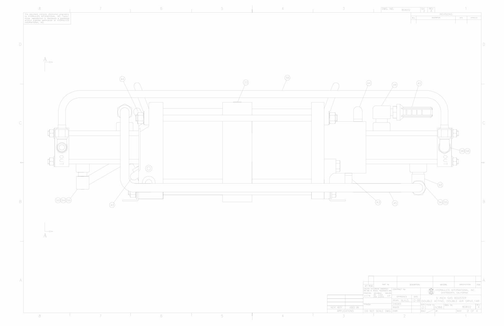
8.3 The Basic Gas Boosting System. Refer to Page 4, then Page 2, Drawing 80832.
Page 4 shows the mechanical connecting rod arrangement between the drive pistons (27) and (28), and the gas sections (26), both –14 ratio. Page 2 shows the exhaust air cooling line, item (45). This assembly picks up cooling air from the first gas section cooling sleeve and routes it to the opposite gas section cooling sleeve and out the exhaust muffler (42). Note: Page 2 and Page 4, Drawing 80832, are opposite assembly views. Therefore, on Page 2, end cap (30) is on the left; the end cap (32) on the right; Page 4, vise versa. Note also the basic operational schematic, Paragraph 5.4.
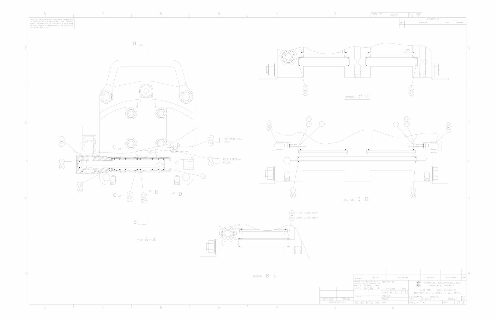
8.4 The Basic Air Cycling System. Refer to Drawing 80217 and Page 3, Drawing 80832.
View C-C shows flow tubes (41). These tubes pressurize or exhaust the left drive cham-bers, Page 4 depending on the position of the cycling valve (30), Drawing 80217. The flow tube (41) in view E-E pressurizes or exhausts the right drive chamber enclosed by diaphragm (7) and piston (28).
NOTE: Views C-C, D-D and E-E are the reverse (backside) of Page 4. Therefore, the valve end cap (30), is on the left and the opposite cap (32) is on the right in views C-C, D-D, and E-E.
When the cycling valve (30) is pressurizing the flow tubes (41) and the left drive cham-bers, Page 4, it is simultaneously connecting the right drive chambers to the exhaust sys-tem. When valve (30) connects the flow tubes (41) to exhaust (view C-C), it simultane-ously pressurizes the right drive chambers and flow tube (41), view E-E.
The cycling spool valve (30) receives input drive air at its center (Ref. Drawing 80217) from which it directs drive air left or right. Drawing 80217 shows that when it shifts right, drive air flows left to the flow tubes (41), view C-C; when it shifts left, drive air flows right directly to the right drive chamber and flow tube (41), view E-E. Drawing 80217 and Page 3, Drawing 80832 both show the valve shifted left.
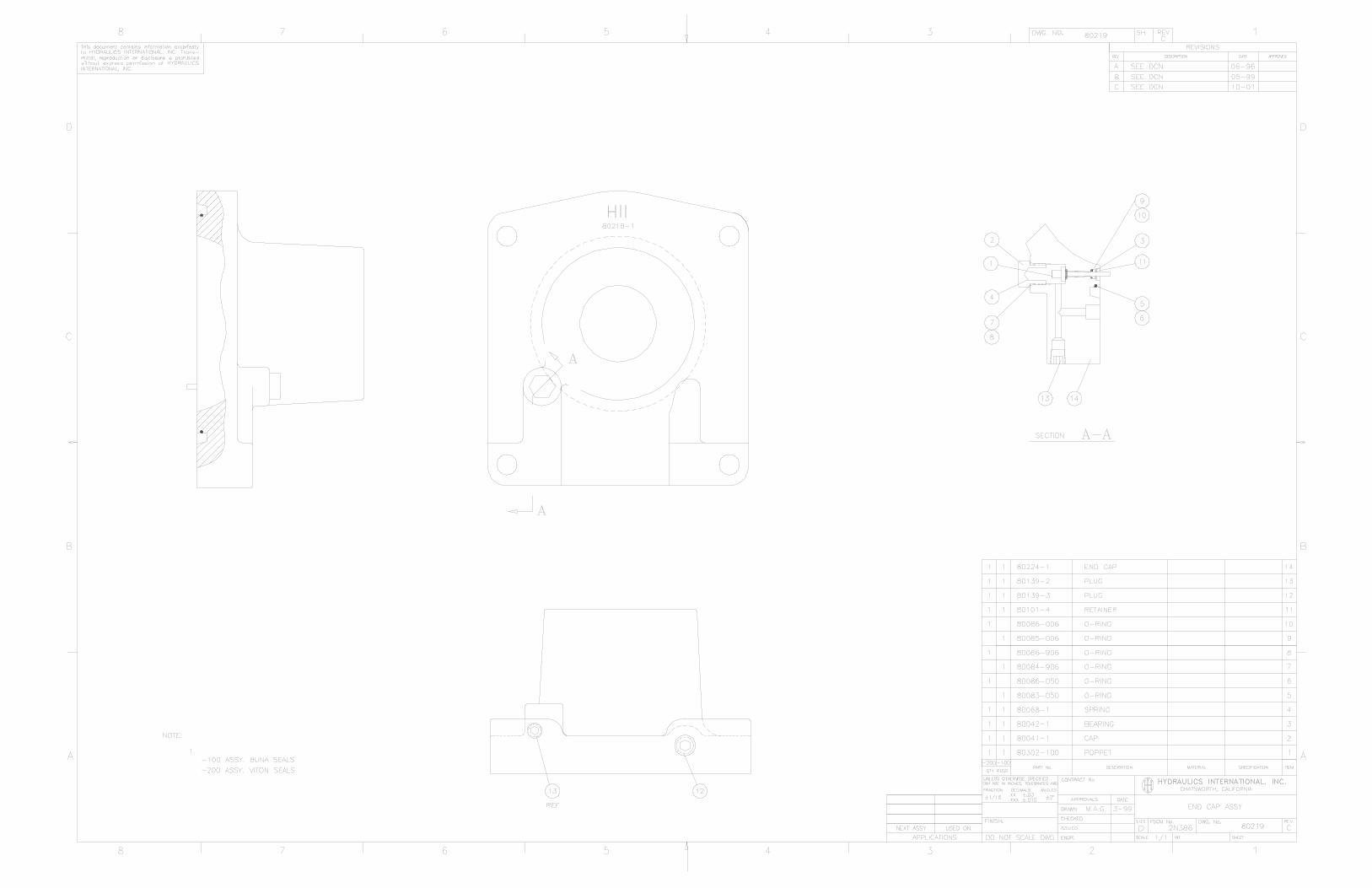
The cycling spool shifts right or left due to the action of the air pilot poppet valves (2), Drawing 80217 and (1) 80219. Note also that a small passage, off the drive-air-in channel
Rev A 1 of 5
5G-DD-14
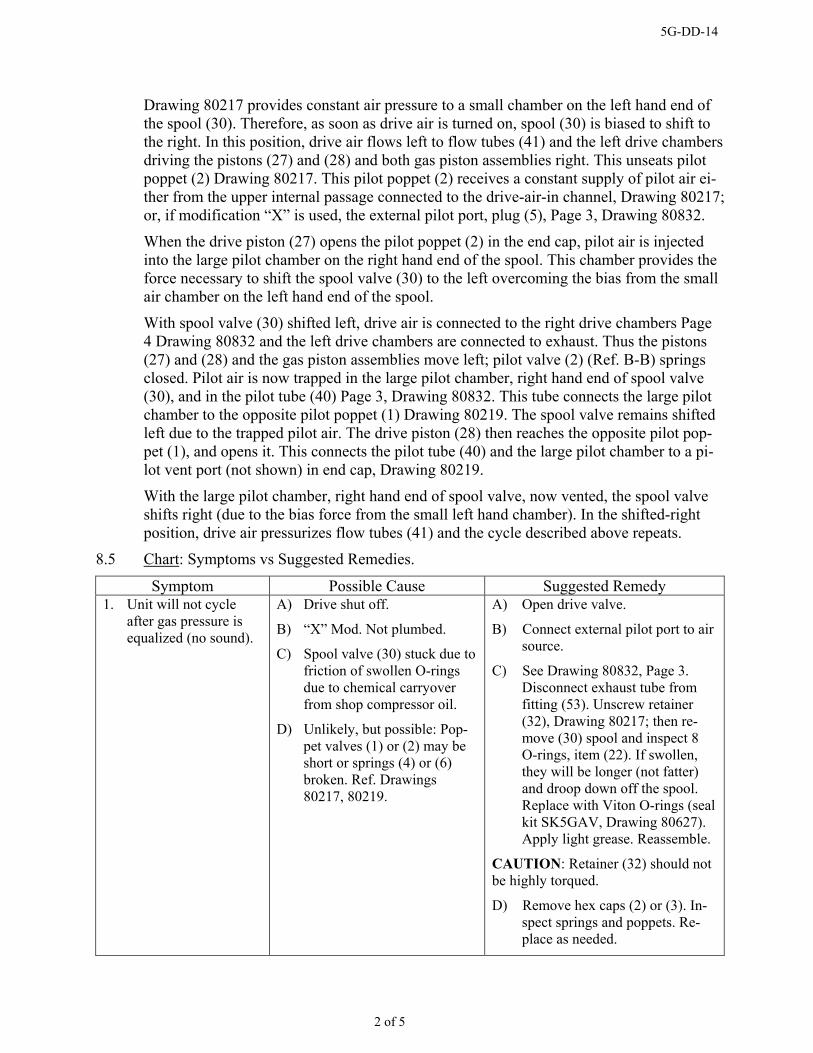
Drawing 80217 provides constant air pressure to a small chamber on the left hand end of the spool (30). Therefore, as soon as drive air is turned on, spool (30) is biased to shift to the right. In this position, drive air flows left to flow tubes (41) and the left drive chambers driving the pistons (27) and (28) and both gas piston assemblies right. This unseats pilot poppet (2) Drawing 80217. This pilot poppet (2) receives a constant supply of pilot air ei-ther from the upper internal passage connected to the drive-air-in channel, Drawing 80217; or, if modification “X” is used, the external pilot port, plug (5), Page 3, Drawing 80832.
When the drive piston (27) opens the pilot poppet (2) in the end cap, pilot air is injected into the large pilot chamber on the right hand end of the spool. This chamber provides the force necessary to shift the spool valve (30) to the left overcoming the bias from the small air chamber on the left hand end of the spool.
With spool valve (30) shifted left, drive air is connected to the right drive chambers Page 4 Drawing 80832 and the left drive chambers are connected to exhaust. Thus the pistons (27) and (28) and the gas piston assemblies move left; pilot valve (2) (Ref. B-B) springs closed. Pilot air is now trapped in the large pilot chamber, right hand end of spool valve (30), and in the pilot tube (40) Page 3, Drawing 80832. This tube connects the large pilot chamber to the opposite pilot poppet (1) Drawing 80219. The spool valve remains shifted left due to the trapped pilot air. The drive piston (28) then reaches the opposite pilot pop-pet (1), and opens it. This connects the pilot tube (40) and the large pilot chamber to a pi-lot vent port (not shown) in end cap, Drawing 80219.
With the large pilot chamber, right hand end of spool valve, now vented, the spool valve shifts right (due to the bias force from the small left hand chamber). In the shifted-right position, drive air pressurizes flow tubes (41) and the cycle described above repeats.
8.5 Chart: Symptoms vs Suggested Remedies.
Symptom Possible Cause Suggested Remedy 1. Unit will not cycle
after gas pressure is equalized (no sound).
A) Drive shut off.
B) “X” Mod. Not plumbed.
C) Spool valve (30) stuck due to friction of swollen O-rings due to chemical carryover from shop compressor oil.
D) Unlikely, but possible: Pop-pet valves (1) or (2) may be short or springs (4) or (6) broken. Ref. Drawings 80217, 80219.
A) Open drive valve.
B) Connect external pilot port to air source.
C) See Drawing 80832, Page 3. Disconnect exhaust tube from fitting (53). Unscrew retainer (32), Drawing 80217; then re-move (30) spool and inspect 8 O-rings, item (22). If swollen, they will be longer (not fatter) and droop down off the spool. Replace with Viton O-rings (seal kit SK5GAV, Drawing 80627). Apply light grease. Reassemble.
CAUTION: Retainer (32) should not be highly torqued.
D) Remove hex caps (2) or (3). In-spect springs and poppets. Re-place as needed.
Rev A 2 of 5
5G-DD-14
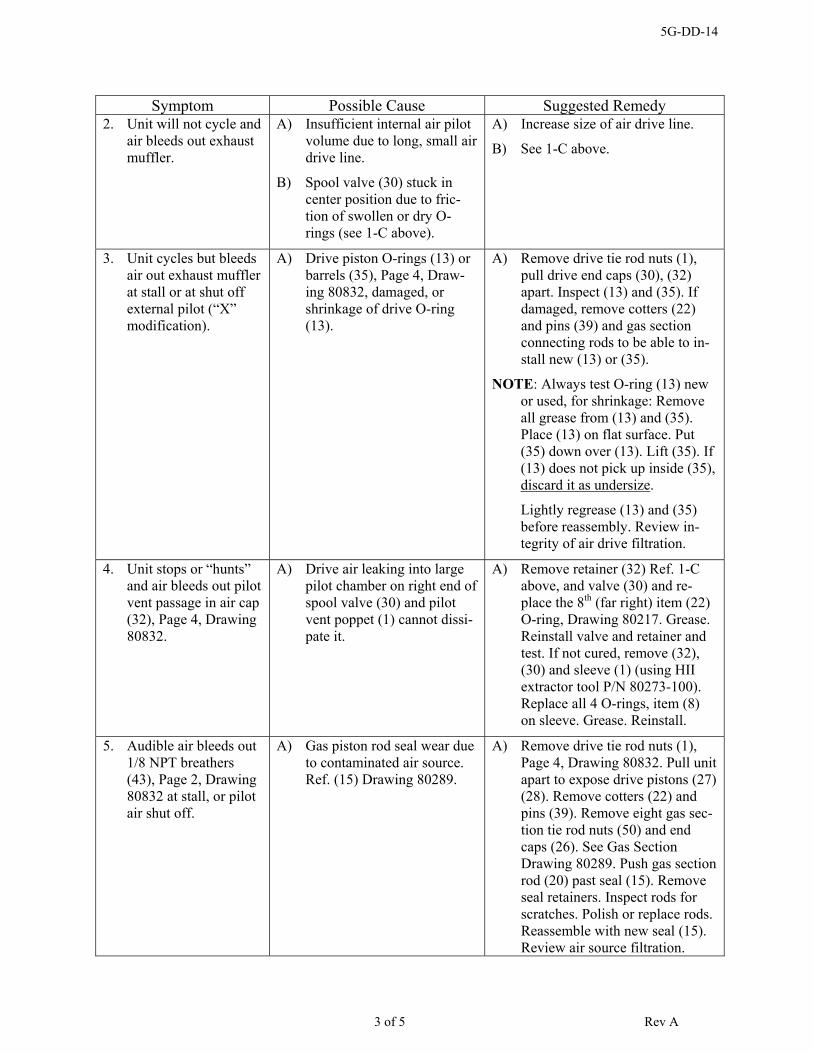
Symptom Possible Cause Suggested Remedy 2. Unit will not cycle and
air bleeds out exhaust muffler.
A) Insufficient internal air pilot volume due to long, small air drive line.
B) Spool valve (30) stuck in center position due to fric-tion of swollen or dry O-rings (see 1-C above).
A) Increase size of air drive line.
B) See 1-C above.
3. Unit cycles but bleeds air out exhaust muffler at stall or at shut off external pilot (“X” modification).
A) Drive piston O-rings (13) or barrels (35), Page 4, Draw-ing 80832, damaged, or shrinkage of drive O-ring (13).
A) Remove drive tie rod nuts (1), pull drive end caps (30), (32) apart. Inspect (13) and (35). If damaged, remove cotters (22) and pins (39) and gas section connecting rods to be able to in-stall new (13) or (35).
NOTE: Always test O-ring (13) new or used, for shrinkage: Remove all grease from (13) and (35). Place (13) on flat surface. Put (35) down over (13). Lift (35). If (13) does not pick up inside (35), discard it as undersize.
Lightly regrease (13) and (35) before reassembly. Review in-tegrity of air drive filtration.
4. Unit stops or “hunts” and air bleeds out pilot vent passage in air cap (32), Page 4, Drawing 80832.
A) Drive air leaking into large pilot chamber on right end of spool valve (30) and pilot vent poppet (1) cannot dissi-pate it.
A) Remove retainer (32) Ref. 1-C above, and valve (30) and re-place the 8th (far right) item (22) O-ring, Drawing 80217. Grease. Reinstall valve and retainer and test. If not cured, remove (32), (30) and sleeve (1) (using HII extractor tool P/N 80273-100). Replace all 4 O-rings, item (8) on sleeve. Grease. Reinstall.
5. Audible air bleeds out 1/8 NPT breathers (43), Page 2, Drawing 80832 at stall, or pilot air shut off.
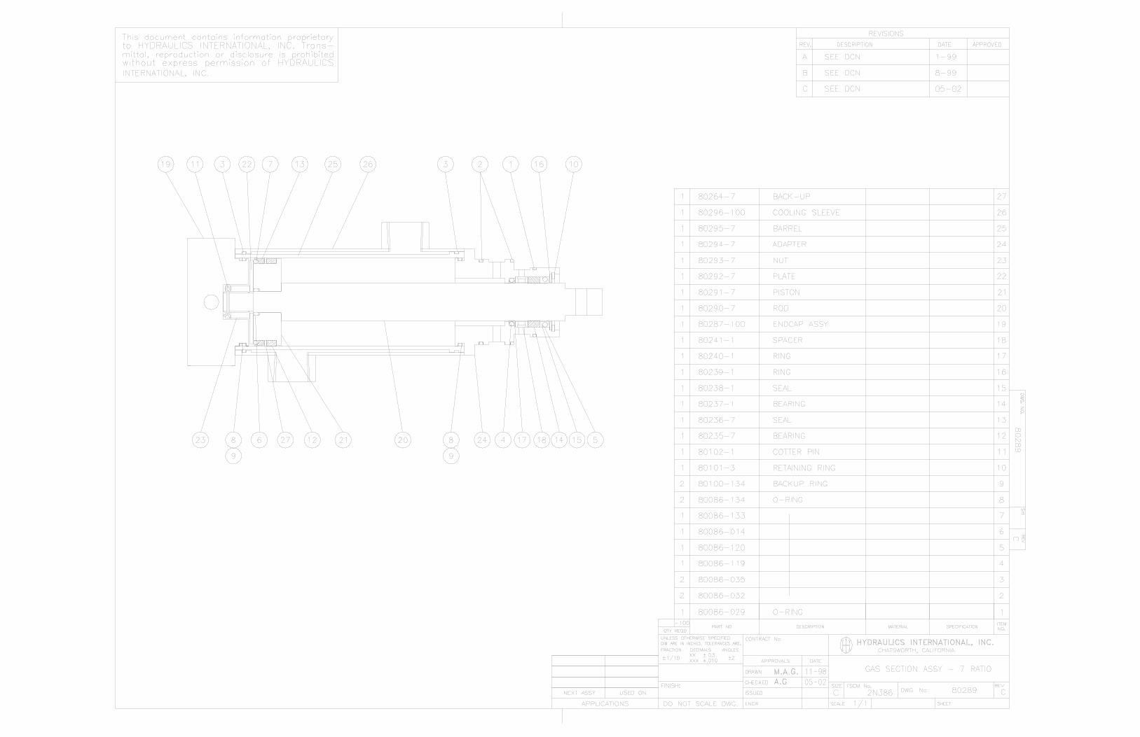
A) Gas piston rod seal wear due to contaminated air source. Ref. (15) Drawing 80289.
A) Remove drive tie rod nuts (1), Page 4, Drawing 80832. Pull unit apart to expose drive pistons (27) (28). Remove cotters (22) and pins (39). Remove eight gas sec-tion tie rod nuts (50) and end caps (26). See Gas Section Drawing 80289. Push gas section rod (20) past seal (15). Remove seal retainers. Inspect rods for scratches. Polish or replace rods. Reassemble with new seal (15). Review air source filtration.
3 of 5 Rev A

5G-DD-14
Symptom Possible Cause Suggested Remedy 6. Unit cycles but output
performance is ques-tionable. Audible gas leakage from breathers (44) Page 2, Drawing 80832, when unit is stopped with gas sup-ply on.
A) Ref. Drawing 80289. Worn gas piston seal (13) or scored barrel (25), due to contami-nated gas source.
A) Disassemble per 5-A above. In-spect and replace all worn parts. Review gas source filtration and/or source of contaminates.
Ref. Drawings 80289, 80628. Gas piston seals & supporting parts must be confined in-side gas barrel before tightening piston nut and installing cotter pin.
6a. Questionable output performance, yet not audible gas breather (44) leakage.
A) Check valves, Drawing 80287 hanging up due to failed springs or contamina-tion.
A) Remove interconnecting gas inlet and outlet tubing. Test each gas section individually per Para-graph 9.0. If under performing, remove check cartridge parts on under performing section. In-spect all parts. Clean and/or re-place as needed. Reassemble.
7. Unit false cycles (short strokes).
A) Pilot air venting prematurely due to damage or contamina-tion of pilot vent poppet (1) in air cap (14), Drawing 80219; or external pilot air leaks from static O-rings sealing the pilot tube (40), Drawing 80832, Page 3, or the pilot poppet hex cap (2) in air cap (14), or leakage at threaded plugs (27) ½ NPT, Drawing 80217 or (13) 1/8 NPT, Drawing 80219.
B) Pilot valve stem seal assem-bly with retaining ring has vibrated loose resulting in nonconcentric valve action.
C) Drive air leaking into the pilot chamber.
A) Inspect pilot vent poppet, spring and seat in air cap. Replace if damaged. Check pilot tube ends and hex cap (2) in end cap (14), Drawing 80219, with soap solu-tion for external leaks. Replace static seal O-rings if soap bub-bles are detected. Check NPT plugs with soap solution. Tighten or retape if leaking.
B) Disassemble drive cylinders and look for loose parts items (3), (4), and (33) (seal kit drawing 80627). Replace item (3), (4) and (33). To insure concentricity, use pilot valve as a centering tool and, by tapping with a light hammer, a tool to evenly deflect the legs of retainer (33), P/N 80101-4.
C) Ref item 4 above.
4 of 5 Rev A

5G-DD-14
9.0 TESTING. Use Ambient Air only. Do not use compressed gas or air at “IN” port.
9.1 Individual Gas Sections.
Setup and Steps:
9.1.1 Loosen nuts on high pressure intercon-necting inlet and outlet tubing.
9.1.2 Remove tubes from both gas sections.
9.1.3 Install 0-500 PSI (minimum) pressure gauge at outlet of section to be tested.
9.1.4 Cycle Booster. If check valves and pis-ton in the first stage are operating properly, it should be able to boost AMBIENT AIR to 250-300 PSI.
9.1.5 Install same gauge at outlet of the other section. Cycle booster. This sec-tion also should be able to boost AM-BIENT AIR to 250-300 PSI if check valves and piston are operating prop-erly.
9.2 Both Sections in Parallel.
Setup and Steps:
9.2.1 Reconnect interconnecting inlet and outlet tubing.
9.2.2 Install 0-500 PSI (minimum) gauge at outlet.
9.2.3 Cycle Booster. It should be able to boost AMBIENT AIR up to 250-300 PSI on outlet gauge using 90-100 PSI air drive.
9.2.4 Shutoff and trap drive air. Using soap solution or “Leak Tec”, check all ex-ternal connections and breathers for leakage. All connections, except breathers, must be bubble tight.
9.3 Drive Section.
Setup per above 9.2.3 but reduce drive air pressure to 15 PSI. Bleed air at gauge. Unit should cycle smoothly.
5 of 5 Rev A