Embed Size (px)
Citation preview

Part No. DOC-10000_REV_A
Fortus® 380/450mc OPERATION ANDMAINTENANCE GUIDE

ii
LIABILITY STATEMENT
The information in this document is subject to change without notice. Stratasys, Inc. shall not be liable for errors contained herein or for incidental or consequential damages in connection with the furnishing, performance, or use of this material. Stratasys, Inc. makes no warranty of any kind with regard to this material, including, but not limited to, the implied warranties of merchantability and fitness for a particular purpose. It is the responsibility of the system owner/material buyer to determine that the Stratasys material is safe, lawful, and technically suitable for the intended application as well as identify the proper disposal (or recycling) method consistent with local environmental regulations. Except as provided in Stratasys' standard conditions of sale, Stratasys shall not be responsible for any loss resulting from any use of its products described herein.
COPYRIGHT STATEMENT
© Copyright 2017 Stratasys Inc. All rights reserved.This document is protected by copyright. No part of this document may be photocopied, reproduced or translated into another language without the prior written consent of Stratasys, Inc. All drawings and information herein are the property of Stratasys Inc. All unauthorized use and reproduction is prohibited.
TRADEMARK ACKNOWLEDGMENTS
Stratasys, Insight, FORTUS, and FDM are trademarks of Stratasys Ltd. and/or subsidiaries or affiliates and may be registered in certain jurisdictions. FORTUS 380mc and 450mc are a registered trademark and service mark of Stratasys Inc. in the United States and other countries. ULTEM™ is a registered trademark of SABIC or affiliates or subsidiaries. All other product names and trademarks are the property of their respective owners.
DECLARATION OF CONFORMITY
Declaration of Conformity information is available from the Stratasys website at: http://www.stratasys.com/customer-support/customer-resource-center/documentation.
EMC CLASS A WARNING
MSDS (MATERIAL SAFETY DATA SHEET)
You can obtain current Material Safety Data Sheets for the material used in the printer is available at: http://www.stratasys.com/materials/material-safety-data-sheets.
Warning: This is a Class A product. In a domestic environment this product may cause radiointerference in which case the user may be required to take adequate measures.

iii
DISPOSAL OF WASTE EQUIPMENT BY USERS IN PRIVATE HOUSEHOLDS IN THE EUROPEAN UNION
This symbol on the product or on its packaging indicates that this product must not be disposed of with your other household waste. Instead, it is your responsibility to dispose of your waste equipment by handing it over to a designated collection point for the recycling of waste electrical and electronic equipment. The separate collection and recycling of your waste equipment at the time of disposal will help to conserve natural resources and ensure that it is recycled in a manner that protects human health and the environment. For more information about where you can drop off your waste equipment for recycling, please contact your local city
office, your household waste disposal service or the shop where you purchased the product.
REVISION LOG
Revision Date Description of Changes
DOC-10000_REV_A July 2017 Initial release.
iv
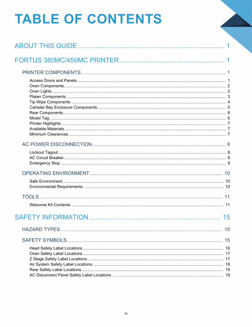
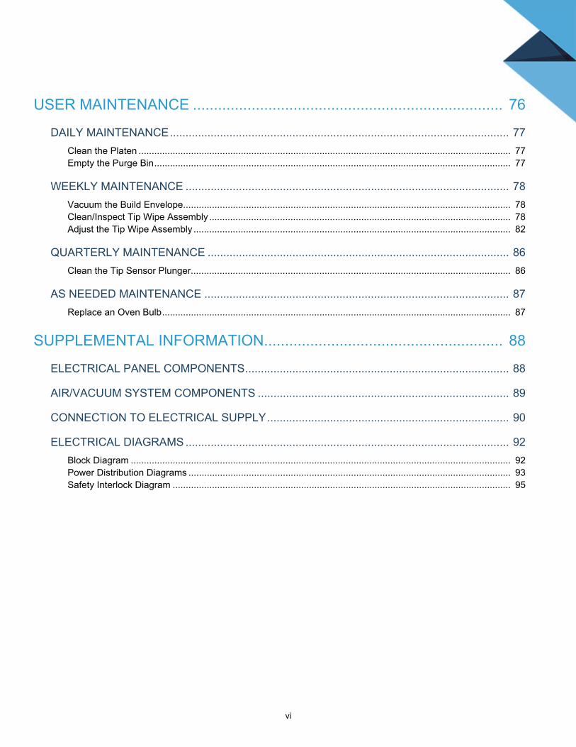
TABLE OF CONTENTS
ABOUT THIS GUIDE ............................................................................... 1
FORTUS 380MC/450MC PRINTER......................................................... 1
PRINTER COMPONENTS......................................................................................................... 1
Access Doors and Panels.................................................................................................................................. 1Oven Components............................................................................................................................................. 2Oven Lights........................................................................................................................................................ 2Platen Components ........................................................................................................................................... 3Tip Wipe Components ....................................................................................................................................... 4Canister Bay Enclosure Components................................................................................................................ 5Rear Components.............................................................................................................................................. 6Model Tag.......................................................................................................................................................... 6Printer Highlights ............................................................................................................................................... 7Available Materials............................................................................................................................................. 7Minimum Clearances......................................................................................................................................... 7
AC POWER DISCONNECTION................................................................................................. 8
Lockout Tagout .................................................................................................................................................. 8AC Circuit Breaker ............................................................................................................................................. 8Emergency Stop ................................................................................................................................................ 9
OPERATING ENVIRONMENT................................................................................................. 10
Safe Environment ............................................................................................................................................ 10Environmental Requirements .......................................................................................................................... 10
TOOLS ..................................................................................................................................... 11
Welcome Kit Contents ..................................................................................................................................... 11
SAFETY INFORMATION ....................................................................... 15
HAZARD TYPES...................................................................................................................... 15
SAFETY SYMBOLS ................................................................................................................. 15
Head Safety Label Locations........................................................................................................................... 16Oven Safety Label Locations........................................................................................................................... 17Z Stage Safety Label Locations....................................................................................................................... 17Air System Safety Label Locations .................................................................................................................. 18Rear Safety Label Locations............................................................................................................................ 19AC Disconnect Panel Safety Label Locations ................................................................................................. 19

v
SAFETY PRECAUTIONS ........................................................................................................ 20
Oven ................................................................................................................................................................ 20Gantry .............................................................................................................................................................. 20Z Stage ............................................................................................................................................................ 20
DOOR LOCKS ......................................................................................................................... 21
STABILITY PADS..................................................................................................................... 21
GENERAL SAFETY PRACTICES............................................................................................ 21
BASIC USER OPERATIONS ................................................................. 22
POWERING ON THE PRINTER .............................................................................................. 22
POWERING OFF THE PRINTER ............................................................................................ 23
USER INTERFACE .................................................................................................................. 24
Build Page ....................................................................................................................................................... 24Queue Page .................................................................................................................................................... 25Tips Page......................................................................................................................................................... 26Calibration Page .............................................................................................................................................. 27Settings Page .................................................................................................................................................. 28Maintenance Page........................................................................................................................................... 29
LOADING/UNLOADING MATERIAL........................................................................................ 30
Loading Material to the Liquefier Tips.............................................................................................................. 30Unloading Material from the Liquefier Tips ...................................................................................................... 32
CHANGING TIPS OR MATERIAL TYPE ................................................................................. 33
Using the Tip Change Wizard.......................................................................................................................... 33Changing Tips.................................................................................................................................................. 66
BASIC JOB BUILD TASKS ...................................................................................................... 69
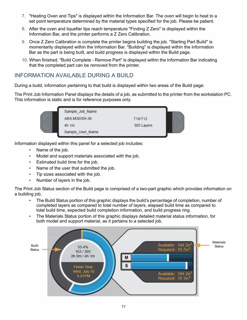
Before a Build .................................................................................................................................................. 69Preparing the Printer........................................................................................................................................ 69Selecting a Job to Build ................................................................................................................................... 70Information Available During a Build................................................................................................................ 71Build Warnings................................................................................................................................................. 72Pausing a Build................................................................................................................................................ 72Aborting a Build ............................................................................................................................................... 73After a Build is Complete ................................................................................................................................. 74Removing a Part from the Printer .................................................................................................................... 75
vi
USER MAINTENANCE .......................................................................... 76
DAILY MAINTENANCE............................................................................................................ 77
Clean the Platen .............................................................................................................................................. 77Empty the Purge Bin........................................................................................................................................ 77
WEEKLY MAINTENANCE ....................................................................................................... 78
Vacuum the Build Envelope............................................................................................................................. 78Clean/Inspect Tip Wipe Assembly ................................................................................................................... 78Adjust the Tip Wipe Assembly ......................................................................................................................... 82
QUARTERLY MAINTENANCE ................................................................................................ 86
Clean the Tip Sensor Plunger.......................................................................................................................... 86
AS NEEDED MAINTENANCE ................................................................................................. 87
Replace an Oven Bulb..................................................................................................................................... 87
SUPPLEMENTAL INFORMATION......................................................... 88
ELECTRICAL PANEL COMPONENTS.................................................................................... 88
AIR/VACUUM SYSTEM COMPONENTS ................................................................................ 89
CONNECTION TO ELECTRICAL SUPPLY............................................................................. 90
ELECTRICAL DIAGRAMS ....................................................................................................... 92
Block Diagram ................................................................................................................................................. 92Power Distribution Diagrams ........................................................................................................................... 93Safety Interlock Diagram ................................................................................................................................. 95
1
ABOUT THIS GUIDEThis guide provides basic instructions for the Fortus 380mc/450mc. Instructions and specifications pertain to both the 380mc and 450mc model, unless otherwise stated. For additional information, contact your Stratasys representative.
FORTUS 380MC/450MC PRINTERThe Fortus 380mc/450mc™ 3D Production System incorporates the latest in innovative technologies to provide you with precise prototypes from a CAD design. Stratasys’ Fused Deposition Modeling (FDM) technology provides prototype parts, including internal features, that can be used to field-test form, fit, and function. Direct Digital Manufacturing (DDM) allows for the creation of customized end-use parts straight from 3D CAD data. The 380mc/450mc printer features a servo/belt driven XY gantry with multiple high temperature modeling material capability.
PRINTER COMPONENTSThe 380mc/450mc printer system consists of the following components.
• The 380mc/450mc Printer• Modeling Material• Support Material• Insight Software Package• A Computer Workstation (not sold by Stratasys)
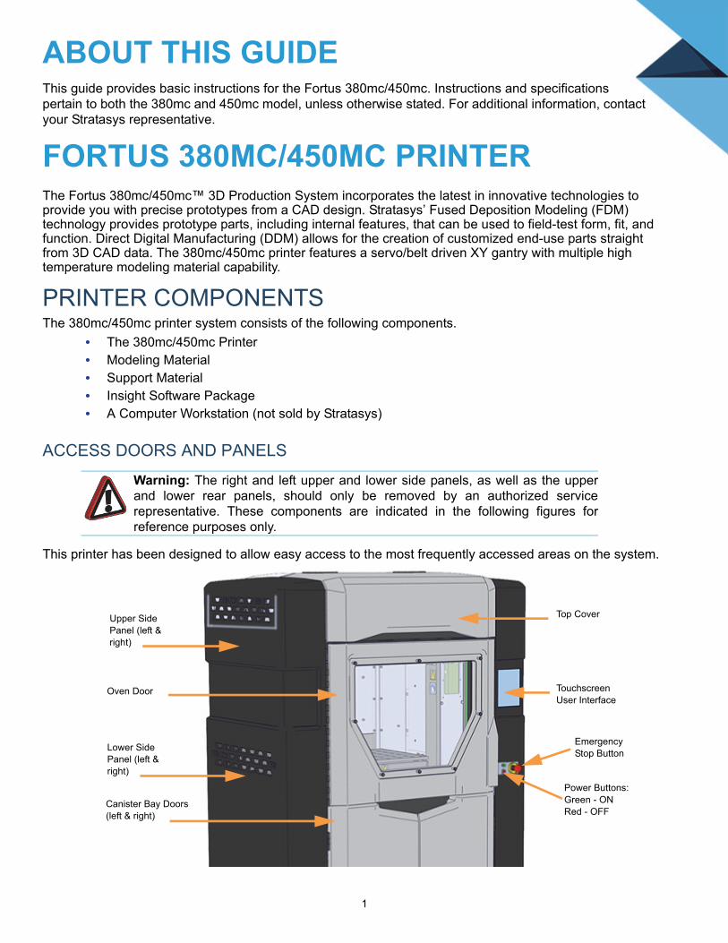
ACCESS DOORS AND PANELS
This printer has been designed to allow easy access to the most frequently accessed areas on the system.
Warning: The right and left upper and lower side panels, as well as the upperand lower rear panels, should only be removed by an authorized servicerepresentative. These components are indicated in the following figures forreference purposes only.
Top Cover
Canister Bay Doors (left & right)
Touchscreen User Interface
Upper Side Panel (left & right)
Lower Side Panel (left & right)
Emergency Stop Button
Power Buttons:Green - ONRed - OFF
Oven Door

2
OVEN COMPONENTS
The oven is comprised of the oven door and everything that you see through the oven door window, including the platen and the tip wipe assembly. The oven is where parts are built.
OVEN LIGHTS
There are four Festoon bulbs (Figure ) mounted on the front upper edge of the oven, two per side, which illuminate the oven. Each bulb is rated at 12 volts.
The Oven Light Control button within the Dashboard indicates the current state of the oven light and allows you to manually turn the light ON of OFF.
Hot Surface: Bulbs are hot. Never touch bulbs when the oven light is turned on. Bulbs should only be removed/replaced when the oven light is turned off.
Tip Wipe Assembly
Purge Chute Access Panel
Platen
OvenDoor
Festoon Bulb (2 per side)
3
PLATEN COMPONENTS
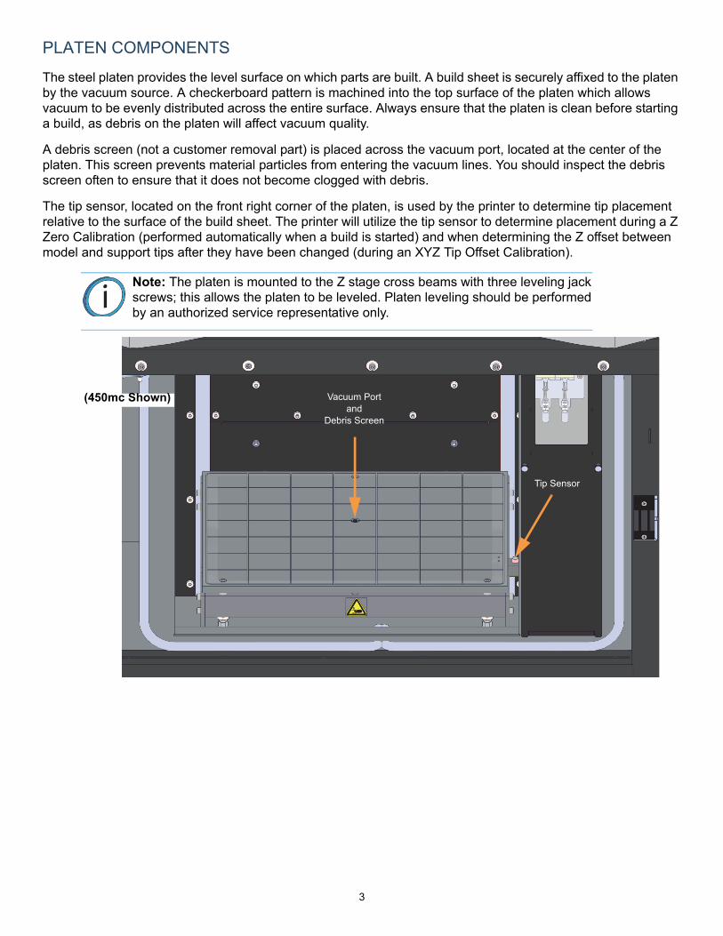
The steel platen provides the level surface on which parts are built. A build sheet is securely affixed to the platen by the vacuum source. A checkerboard pattern is machined into the top surface of the platen which allows vacuum to be evenly distributed across the entire surface. Always ensure that the platen is clean before starting a build, as debris on the platen will affect vacuum quality.
A debris screen (not a customer removal part) is placed across the vacuum port, located at the center of the platen. This screen prevents material particles from entering the vacuum lines. You should inspect the debris screen often to ensure that it does not become clogged with debris.
The tip sensor, located on the front right corner of the platen, is used by the printer to determine tip placement relative to the surface of the build sheet. The printer will utilize the tip sensor to determine placement during a Z Zero Calibration (performed automatically when a build is started) and when determining the Z offset between model and support tips after they have been changed (during an XYZ Tip Offset Calibration).
Note: The platen is mounted to the Z stage cross beams with three leveling jackscrews; this allows the platen to be leveled. Platen leveling should be performedby an authorized service representative only.
Vacuum Port and
Debris Screen
Tip Sensor
(450mc Shown)
4
TIP WIPE COMPONENTS
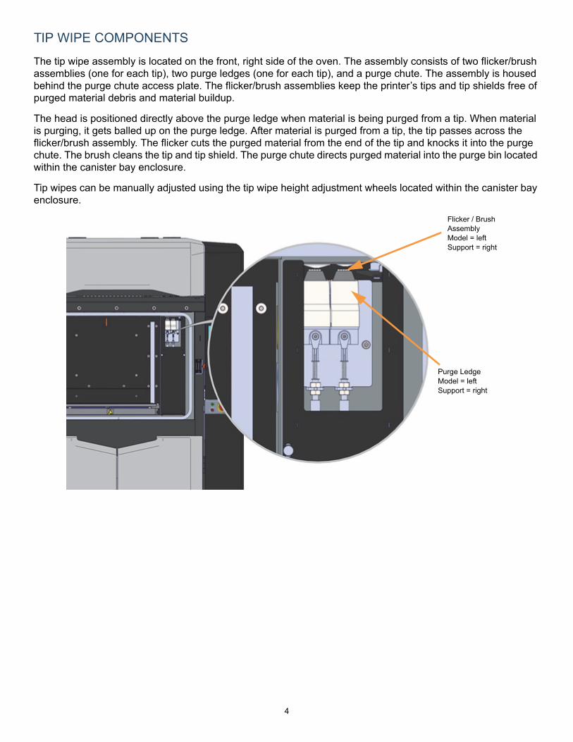
The tip wipe assembly is located on the front, right side of the oven. The assembly consists of two flicker/brush assemblies (one for each tip), two purge ledges (one for each tip), and a purge chute. The assembly is housed behind the purge chute access plate. The flicker/brush assemblies keep the printer’s tips and tip shields free of purged material debris and material buildup.
The head is positioned directly above the purge ledge when material is being purged from a tip. When material is purging, it gets balled up on the purge ledge. After material is purged from a tip, the tip passes across the flicker/brush assembly. The flicker cuts the purged material from the end of the tip and knocks it into the purge chute. The brush cleans the tip and tip shield. The purge chute directs purged material into the purge bin located within the canister bay enclosure.
Tip wipes can be manually adjusted using the tip wipe height adjustment wheels located within the canister bay enclosure.
Flicker / Brush Assembly Model = leftSupport = right
Purge LedgeModel = leftSupport = right

5
CANISTER BAY ENCLOSURE COMPONENTS
The model and support material canister bays are accessed by opening the canister bay doors on the front of the printer. The canister bay doors do not contain electromagnetic locks and can therefore be opened while the printer is building.
Canister Status LEDs
Model Material Canister Bay(M1 & M2)
Support Material Canister Bay
(S1 & S2)
Canister DriveRelease Knobs
Storage Area
Purge Waste Bin & Waste Bin Door
Tip Wipe Height Adjustment Wheels (Model - top wheel Support - bottom wheel)
Canister Drives
(450mc Shown)

6
REAR COMPONENTS
MODEL TAG
The model tag lists the printer’s model number, part number, and power requirements. This tag also lists all patent numbers associated with the printer, some FCC compliance information, voltage warnings and the Stratasys web address. Use the information on these tags when identifying your printer with Customer Support.
AC Disconnect Lever
Lockout Bar
Power Cable Connection
AC Circuit Breaker (OFF Position)
Ethernet Network Connection (RJ45)
Optional UPS Connection

7
PRINTER HIGHLIGHTS
• Envelope Size: 380mc - 14 x 12 x 12 inch (355.6 x 304.8 x 304.8 mm)450mc - 16 x 14 x 16 inch (406.4 x 355.6 x 406.4 mm)
• Material Canister Bays:380mc - 1 model, 1 support450mc - 2 model, 2 support
• Touchscreen Graphical User Interface
AVAILABLE MATERIALS
Three material options are available for the 450mc. Option details are as follows:
In addition to the material bundles listed above, a stand-alone license can be purchased for any of these materials.
MINIMUM CLEARANCES
Option Option Details
Standard ABS-M30 (all colors), ABS-M30i, ABS-ESD7, and ASA (all colors) model material with SR-30 or SR-35 support material.
Engineering PC, PC-ABS, PC-ISO, and Nylon12 model material with associated PC_S, SR-100 and SR-110 support materials.
High Performance ULTEM 9085 and ULTEM Black model material with associated Ultem support material (ULT_S), Ultem 1010 model material with associated ULTEM 1010 support material (U1010S1), ST130 model material with associated ST130-S support material, and Nylon12 CF model material with associated SR-110 support material.
Side Clearance Minimum 30 inches (76.20 cm) on each side
Rear Clearance Minimum 12 inches (30.48 cm)
Front Clearance Minimum 36 inches (91.44 cm)
Overhead Clearance Minimum 24 inches (60.96 cm)
8
AC POWER DISCONNECTION
LOCKOUT TAGOUT
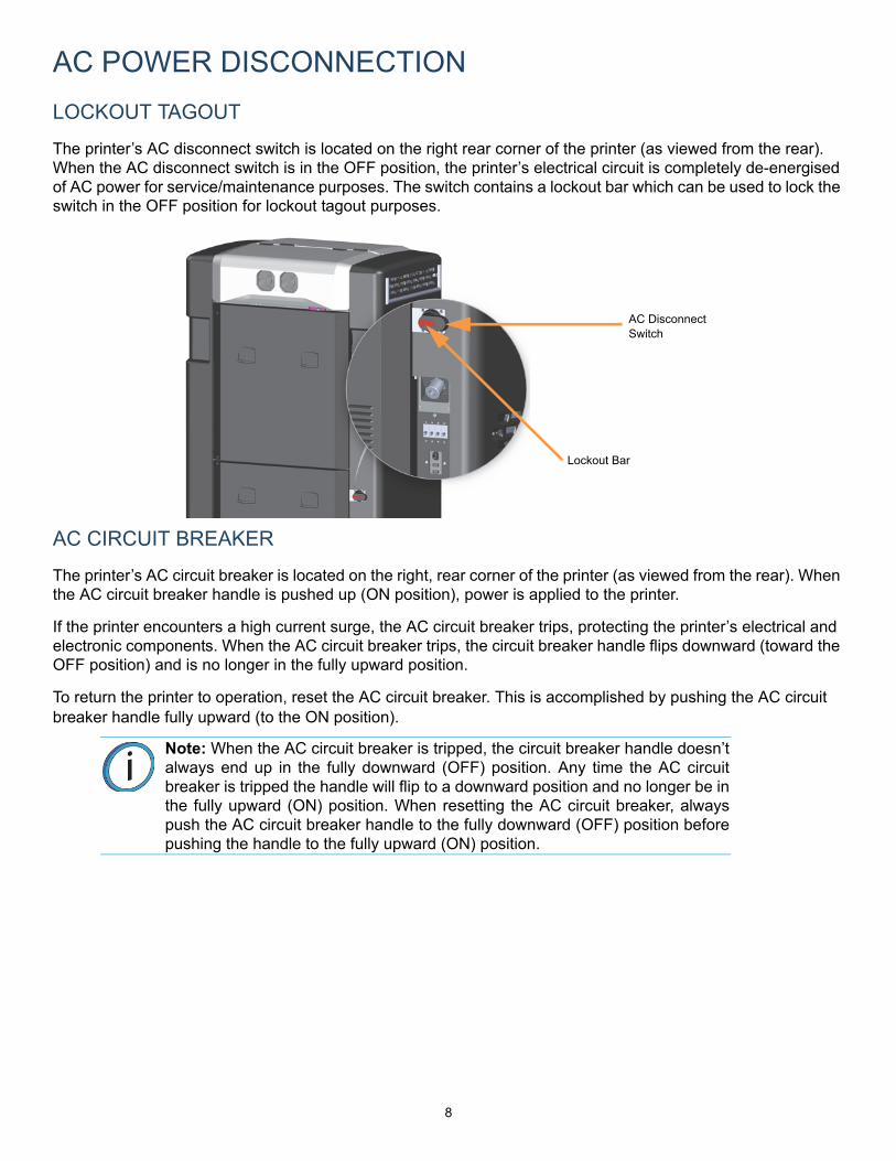
The printer’s AC disconnect switch is located on the right rear corner of the printer (as viewed from the rear). When the AC disconnect switch is in the OFF position, the printer’s electrical circuit is completely de-energised of AC power for service/maintenance purposes. The switch contains a lockout bar which can be used to lock the switch in the OFF position for lockout tagout purposes.
AC CIRCUIT BREAKER
The printer’s AC circuit breaker is located on the right, rear corner of the printer (as viewed from the rear). When the AC circuit breaker handle is pushed up (ON position), power is applied to the printer.
If the printer encounters a high current surge, the AC circuit breaker trips, protecting the printer’s electrical and electronic components. When the AC circuit breaker trips, the circuit breaker handle flips downward (toward the OFF position) and is no longer in the fully upward position.
To return the printer to operation, reset the AC circuit breaker. This is accomplished by pushing the AC circuit breaker handle fully upward (to the ON position).
Note: When the AC circuit breaker is tripped, the circuit breaker handle doesn’talways end up in the fully downward (OFF) position. Any time the AC circuitbreaker is tripped the handle will flip to a downward position and no longer be inthe fully upward (ON) position. When resetting the AC circuit breaker, alwayspush the AC circuit breaker handle to the fully downward (OFF) position beforepushing the handle to the fully upward (ON) position.
AC Disconnect Switch
Lockout Bar
9
EMERGENCY STOP
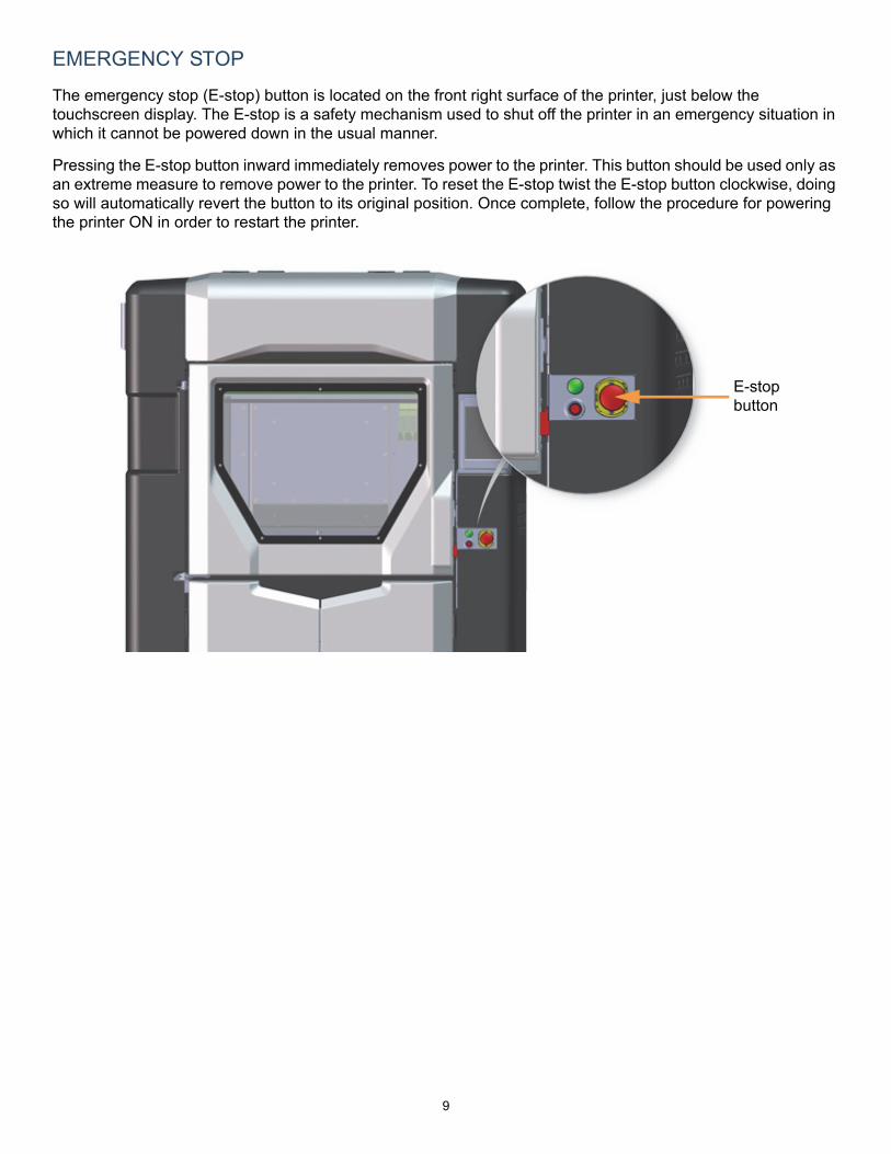
The emergency stop (E-stop) button is located on the front right surface of the printer, just below the touchscreen display. The E-stop is a safety mechanism used to shut off the printer in an emergency situation in which it cannot be powered down in the usual manner.
Pressing the E-stop button inward immediately removes power to the printer. This button should be used only as an extreme measure to remove power to the printer. To reset the E-stop twist the E-stop button clockwise, doing so will automatically revert the button to its original position. Once complete, follow the procedure for powering the printer ON in order to restart the printer.
E-stopbutton

10
OPERATING ENVIRONMENT
SAFE ENVIRONMENT
• Connect equipment to a grounded facility power source. Do not defeat or bypass the ground lead.• Know the location of equipment branch circuit interrupters or circuit breakers and how to turn them
on and off in case of emergency.• Know the location of fire extinguishers and how to use them. Use only ABC type extinguishers on
electrical fires.• Know local procedures for first aid and emergency assistance at the customer facility.• Use adequate lighting at the equipment.• Maintain the recommended range of temperature and humidity in equipment area.
• Do not use this product in an environment containing volatile or flammable compounds.
ENVIRONMENTAL REQUIREMENTS
• The 380mc and 450mc are for indoor use only.• Air quality conditions with excessive solid particulates (conductive or
non-conductive) may result in system damage.• Air quality conditions in which airborne oils are allowed to accumulate on or within the printer
can damage the plastic components.• Operating temperature shall be in the range of 65°F to 86°F (18°C to 30°C), with relative
humidity range of 30% to 70% non-condensing.• Storage temperature shall be in the range of -40°F to 129.2°F (-40°C to 54°C), with relative
humidity range of 10% to 85% non-condensing.• Altitude shall not exceed 6561.68 feet (2000 m).• Noise emission (acoustic):
• <65dBA when idle
• <66dBA when building
Note: The 380mc and 450mc printers are capable of generating vibrationsdepending mainly on part build geometry and material characteristics. Thisconsideration will need to be taken into account if locating the printer nearvibration sensitive equipment.
11
TOOLS
WELCOME KIT CONTENTS
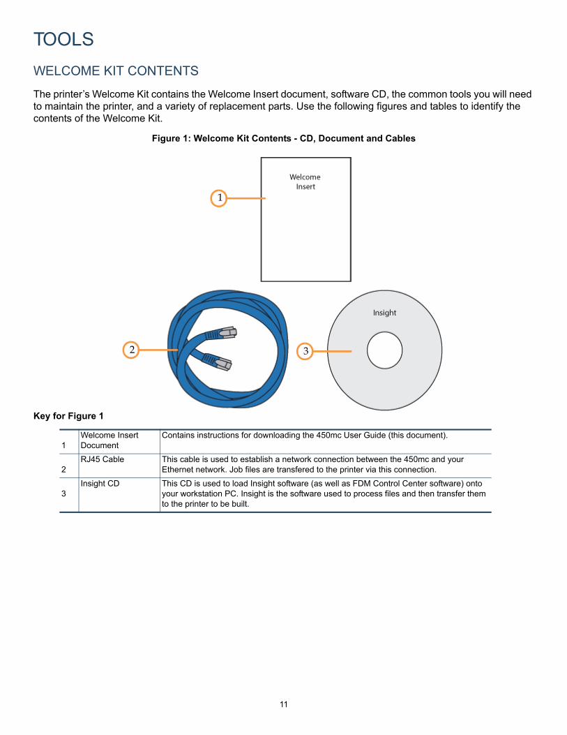
The printer’s Welcome Kit contains the Welcome Insert document, software CD, the common tools you will need to maintain the printer, and a variety of replacement parts. Use the following figures and tables to identify the contents of the Welcome Kit.
Figure 1: Welcome Kit Contents - CD, Document and Cables
Key for Figure 1
1Welcome Insert Document
Contains instructions for downloading the 450mc User Guide (this document).
2RJ45 Cable This cable is used to establish a network connection between the 450mc and your
Ethernet network. Job files are transfered to the printer via this connection.
3Insight CD This CD is used to load Insight software (as well as FDM Control Center software) onto
your workstation PC. Insight is the software used to process files and then transfer them to the printer to be built.
1
32

12
Figure 2: Welcome Kit Contents - Tools
Key for Figure 2
1Leather Safety Gloves
Printer components may be extremely hot. To prevent burns or other injuries, these gloves should be worn any time you see the gloves safety sign.
2Magnetic Handle Pick Set
Occasionally, you may need to use these picks to aid in the removal of breakaway supports or clearing debris which have accumulated on the head and/or tips.
3Platen Dusting Brush
This tool is used to brush away material debris when cleaning the platen. Always ensure that the platen is clean before starting a build, as debris on the platen will affect vacuum quality.
4Hex Ball End Driver(9/64)
This is used throughout the process of changing the printer’s tips.
510x Lighted Magnifier
This tool is included to aid you with performing an XYZ Tip Offset Calibration which requires you to view small toolpath relationships. Batteries for this item (2 C batteries) are not included.
6 5” Cutters These are used to cut a canister’s filament when unloading and removing materials from the printer.
7Needle Nose Pliers
(7 1/8)
Occasionally, you may need to use pliers to aid in the removal of breakaway supports or clearing debris which have accumulated on the head and/or tips.
2
1
3
4
5
6
7
13
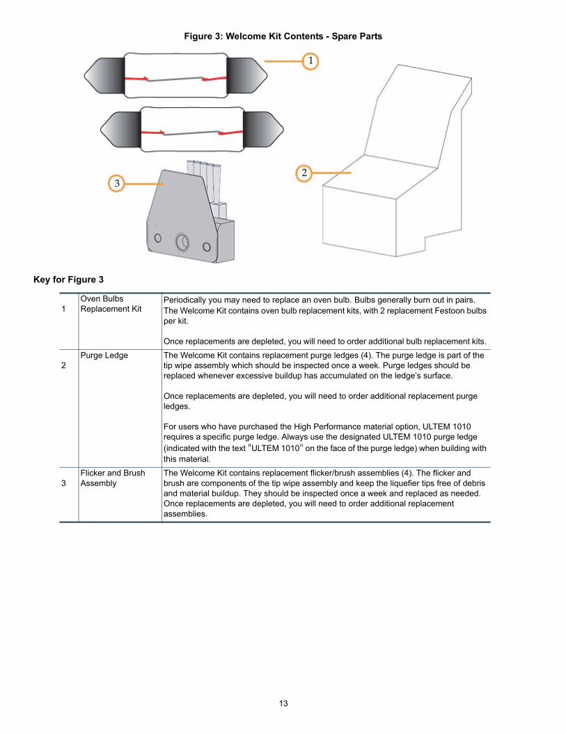
Figure 3: Welcome Kit Contents - Spare Parts
Key for Figure 3
1Oven Bulbs Replacement Kit
Periodically you may need to replace an oven bulb. Bulbs generally burn out in pairs. The Welcome Kit contains oven bulb replacement kits, with 2 replacement Festoon bulbs per kit.
Once replacements are depleted, you will need to order additional bulb replacement kits.
2Purge Ledge The Welcome Kit contains replacement purge ledges (4). The purge ledge is part of the
tip wipe assembly which should be inspected once a week. Purge ledges should be replaced whenever excessive buildup has accumulated on the ledge’s surface.
Once replacements are depleted, you will need to order additional replacement purge ledges.
For users who have purchased the High Performance material option, ULTEM 1010 requires a specific purge ledge. Always use the designated ULTEM 1010 purge ledge (indicated with the text "ULTEM 1010" on the face of the purge ledge) when building with this material.
3Flicker and Brush Assembly
The Welcome Kit contains replacement flicker/brush assemblies (4). The flicker and brush are components of the tip wipe assembly and keep the liquefier tips free of debris and material buildup. They should be inspected once a week and replaced as needed. Once replacements are depleted, you will need to order additional replacement assemblies.
1
23
14
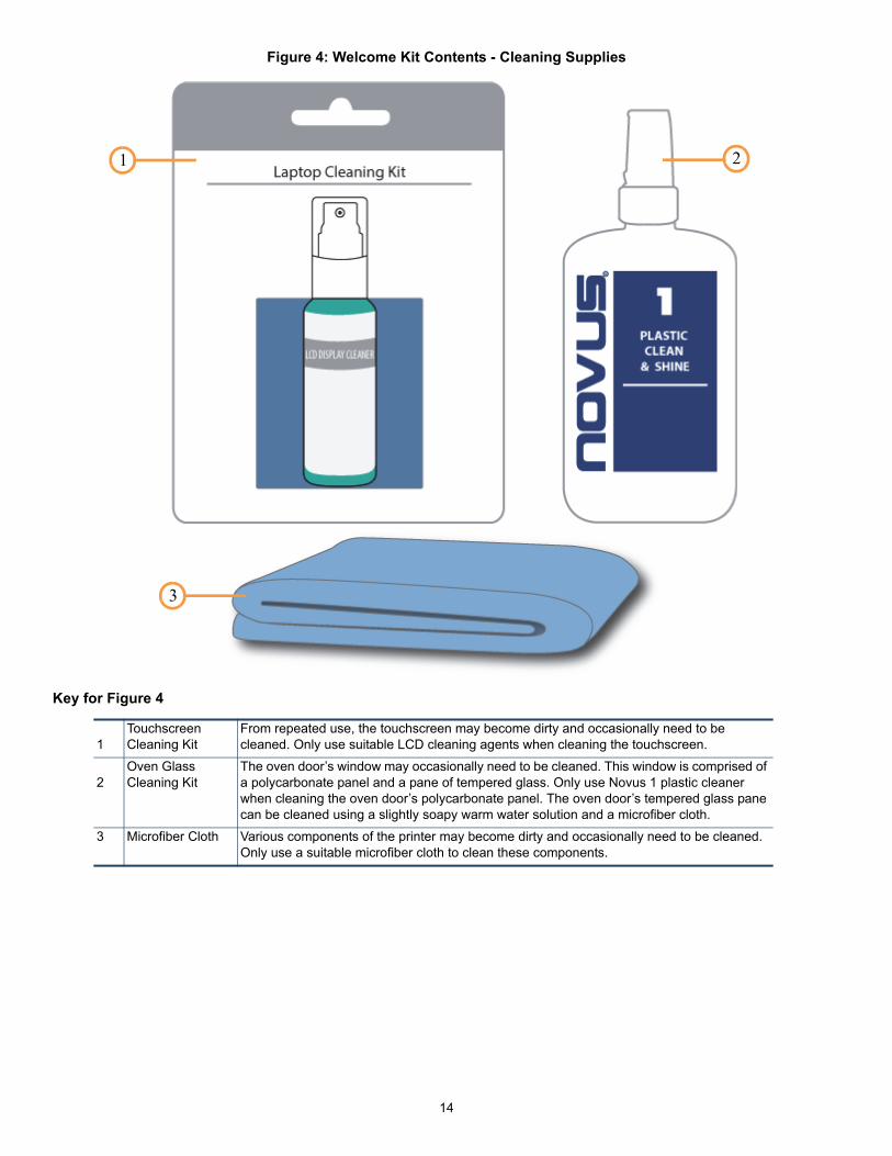
Figure 4: Welcome Kit Contents - Cleaning Supplies
Key for Figure 4
1Touchscreen Cleaning Kit
From repeated use, the touchscreen may become dirty and occasionally need to be cleaned. Only use suitable LCD cleaning agents when cleaning the touchscreen.
2Oven Glass Cleaning Kit
The oven door’s window may occasionally need to be cleaned. This window is comprised of a polycarbonate panel and a pane of tempered glass. Only use Novus 1 plastic cleaner when cleaning the oven door’s polycarbonate panel. The oven door’s tempered glass pane can be cleaned using a slightly soapy warm water solution and a microfiber cloth.
3 Microfiber Cloth Various components of the printer may become dirty and occasionally need to be cleaned. Only use a suitable microfiber cloth to clean these components.
21
3

15
SAFETY INFORMATIONThe following basic safety tips are given to ensure safe installation, operation, and maintenance of Stratasys equipment and are not to be considered as comprehensive on matters of safety. The Fortus 450mc printer is designed to be a safe and reliable rapid prototyping printer. Access to areas of the printer are potentially dangerous.
HAZARD TYPES
Stratasys recommends that all services be performed by qualified personnel. All personnel working on or around this printer should be knowledgeable of what the following hazard classifications mean throughout this guide.
• Warnings and Cautions precede the paragraph to which they pertain.
SAFETY SYMBOLS
We make every effort to ensure that our printers are safe and reliable at all times. However, there will be times when you must access areas of the printer where potentially high voltages, hot temperatures, and/or moving mechanical components could cause severe injury.
Warning: Indicates a potentially hazardous situation which, if not avoided, mayresult in injury or death.
Caution: Indicates a situation which, if not avoided, could result in damage toequipment.
Note: Indicates additional information relative to the current topic.
Note: Always read and adhere to safety statements, and be aware of the following safetysigns when you see them on the printer.
High Voltage: The high voltage sign indicates the presence of high voltages. Always stayaway from any exposed electrical circuitry. It is recommended that all jewelry be removed.
Hot Surface: The hot surface sign indicates the presence of devices with high temperatures.Always use extra care when working around heated components. Always wear the safetygloves provided in the Welcome Kit.
Head temperatures in the printer can exceed 450°C (800°F).

16
HEAD SAFETY LABEL LOCATIONS
Gloves: The gloves sign indicates that if you enter the area specified by the symbol you mustwear safety gloves (provided in the Welcome Kit) which have been approved for hightemperatures.
Crushed Hand: The crushed hand sign indicates that a hazard exists where you could getyour hand crushed between two objects. One or more objects move in the area that you areworking.
Arc Flash: The arc flash sign indicates that a hazard exists which may result in theoccurrence of an arc flash. Do not operate controls or open covers without appropriatepersonal protection equipment.
Rotating Blade: The rotating blade sign indicates the presence of a rotating fan blade.Rotating fan blades can cause serious bodily injury or cuts. Always keeps hands clear ofrotating blades.

17
OVEN SAFETY LABEL LOCATIONS
Z STAGE SAFETY LABEL LOCATIONS

18
AIR SYSTEM SAFETY LABEL LOCATIONS
Compressed Air System
Vacuum System
19
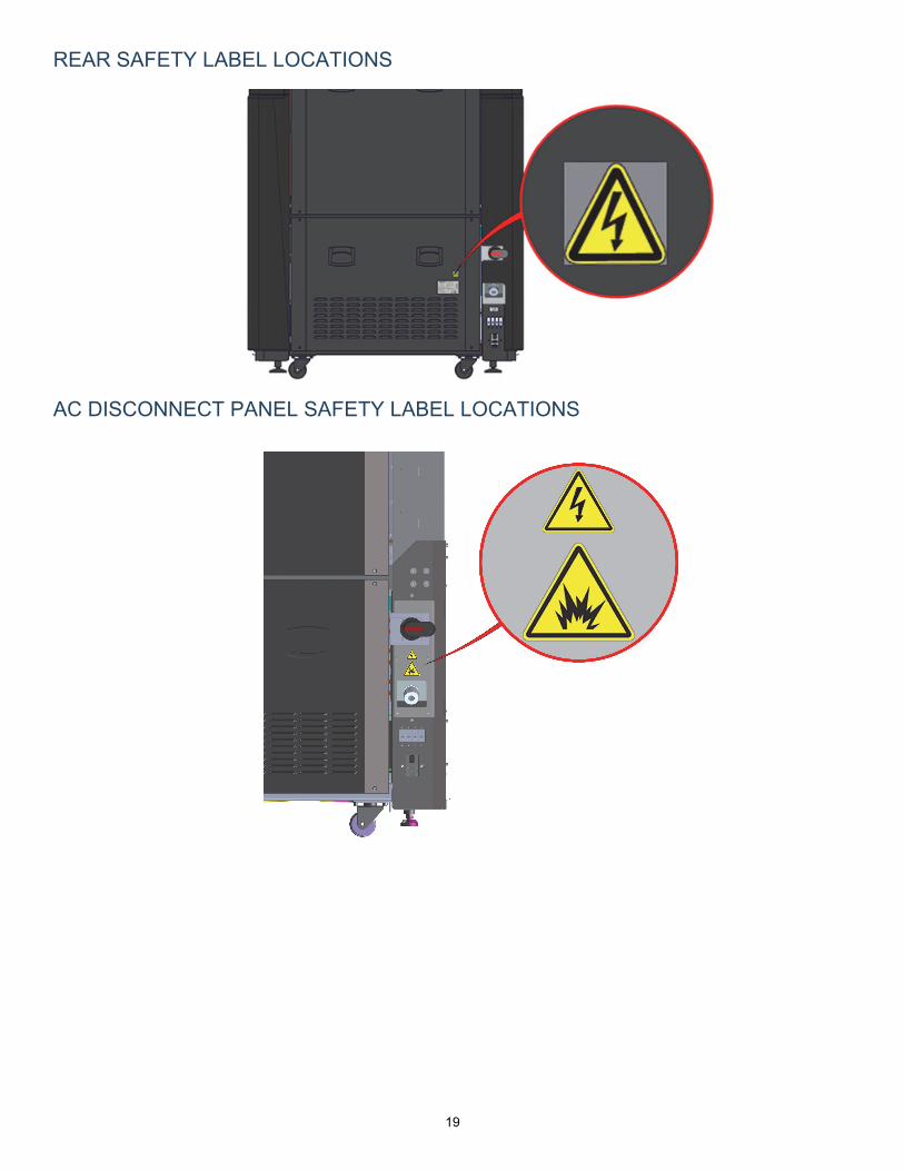
REAR SAFETY LABEL LOCATIONS
AC DISCONNECT PANEL SAFETY LABEL LOCATIONS
20
SAFETY PRECAUTIONS
The following components and areas of the printer are potential safety hazards. Take adequate precautions when using and maintaining the printer.
OVEN
GANTRY
Z STAGE
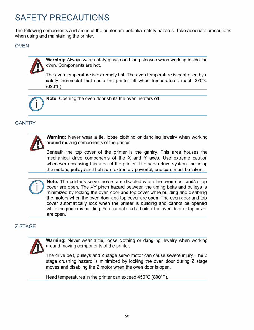
Warning: Always wear safety gloves and long sleeves when working inside theoven. Components are hot.
The oven temperature is extremely hot. The oven temperature is controlled by asafety thermostat that shuts the printer off when temperatures reach 370°C(698°F).
Note: Opening the oven door shuts the oven heaters off.
Warning: Never wear a tie, loose clothing or dangling jewelry when workingaround moving components of the printer.
Beneath the top cover of the printer is the gantry. This area houses themechanical drive components of the X and Y axes. Use extreme cautionwhenever accessing this area of the printer. The servo drive system, includingthe motors, pulleys and belts are extremely powerful, and care must be taken.
Note: The printer’s servo motors are disabled when the oven door and/or topcover are open. The XY pinch hazard between the timing belts and pulleys isminimized by locking the oven door and top cover while building and disablingthe motors when the oven door and top cover are open. The oven door and topcover automatically lock when the printer is building and cannot be openedwhile the printer is building. You cannot start a build if the oven door or top coverare open.
Warning: Never wear a tie, loose clothing or dangling jewelry when workingaround moving components of the printer.
The drive belt, pulleys and Z stage servo motor can cause severe injury. The Zstage crushing hazard is minimized by locking the oven door during Z stagemoves and disabling the Z motor when the oven door is open.
Head temperatures in the printer can exceed 450°C (800°F).
21
DOOR LOCKSSensors are used to communicate the status of the oven door and the top cover to the printer. For safety reasons, the oven door and top cover must be closed before the X, Y, and Z motors will operate. Electromagnetic locks ensure that the oven door and top cover remain securely closed when the printer is building.
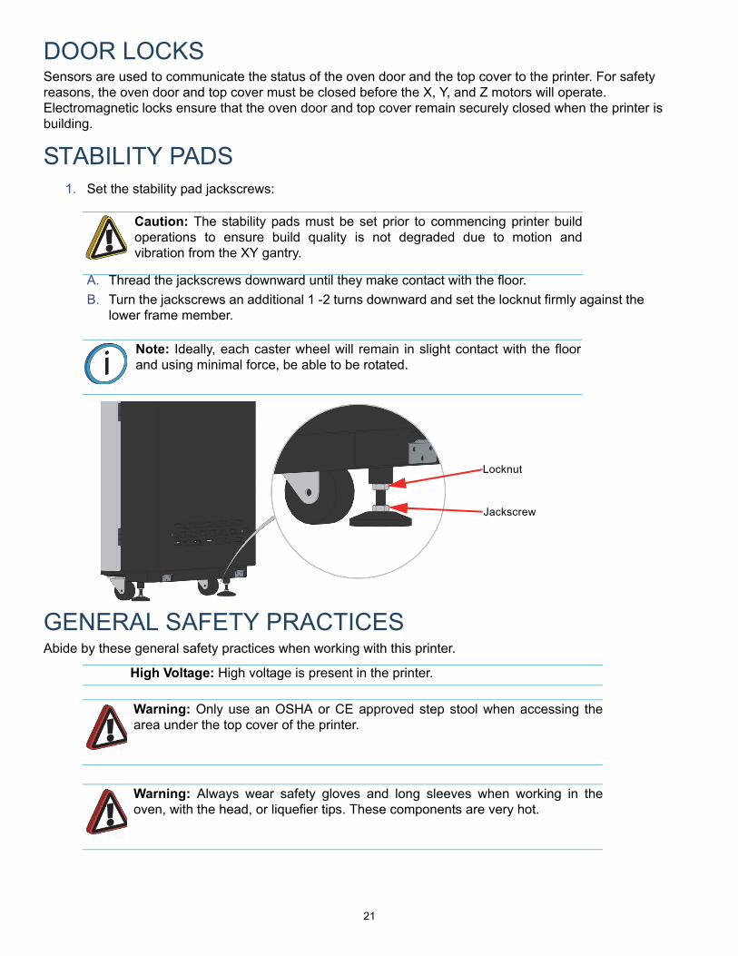
STABILITY PADS1. Set the stability pad jackscrews:
A. Thread the jackscrews downward until they make contact with the floor.
B. Turn the jackscrews an additional 1 -2 turns downward and set the locknut firmly against the lower frame member.
GENERAL SAFETY PRACTICESAbide by these general safety practices when working with this printer.
Caution: The stability pads must be set prior to commencing printer buildoperations to ensure build quality is not degraded due to motion andvibration from the XY gantry.
Note: Ideally, each caster wheel will remain in slight contact with the floorand using minimal force, be able to be rotated.
High Voltage: High voltage is present in the printer.
Warning: Only use an OSHA or CE approved step stool when accessing thearea under the top cover of the printer.
Warning: Always wear safety gloves and long sleeves when working in theoven, with the head, or liquefier tips. These components are very hot.
Jackscrew
Locknut
22
BASIC USER OPERATIONS
POWERING ON THE PRINTER
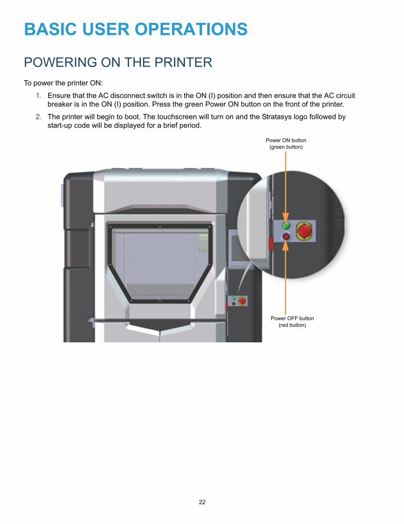
To power the printer ON:
1. Ensure that the AC disconnect switch is in the ON (I) position and then ensure that the AC circuit breaker is in the ON (I) position. Press the green Power ON button on the front of the printer.
2. The printer will begin to boot. The touchscreen will turn on and the Stratasys logo followed by start-up code will be displayed for a brief period.
Power ON button(green button)
Power OFF button(red button)

23
3. Once the printer boots up "Initializing" will be displayed on the touchscreen, followed by "Starting". "Initializing" followed by "Starting" will also be displayed within the Information Bar. The icons within the Dashboard will be blank until this process is complete.
4. After the initialization and start up process is complete, the printer will automatically perform an XY Home Calibration.
5. Once calibration is complete, the Dashboard will refresh and display the printer’s current configuration (materials and tips) information. If this is the first time you’ve powered up the printer, all material and tip status icons will be yellow indicating that tips and material canisters need to be installed.
POWERING OFF THE PRINTER
To power the printer OFF:
1. Ensure that the printer is stopped (idle) and is not building.
2. Press the red Power OFF button on the front of the printer.
3. The oven light and User Interface will turn off, and after a couple of minutes the printer will shutdown.
Note: This procedure only powers down the electronics. To completelydisengage power to the printer, you must flip the AC circuit breaker to the OFFposition and then turn the AC disconnect switch to the OFF (O) position.
24
USER INTERFACE
The User Interface is broken up into six main pages providing access to the Build, Queue, Tips, Calibration, Settings, and Maintenance functions of the printer. A Navigation Bar provides one-touch access to each of the main pages, allowing you to perform tasks within that page.
BUILD PAGE
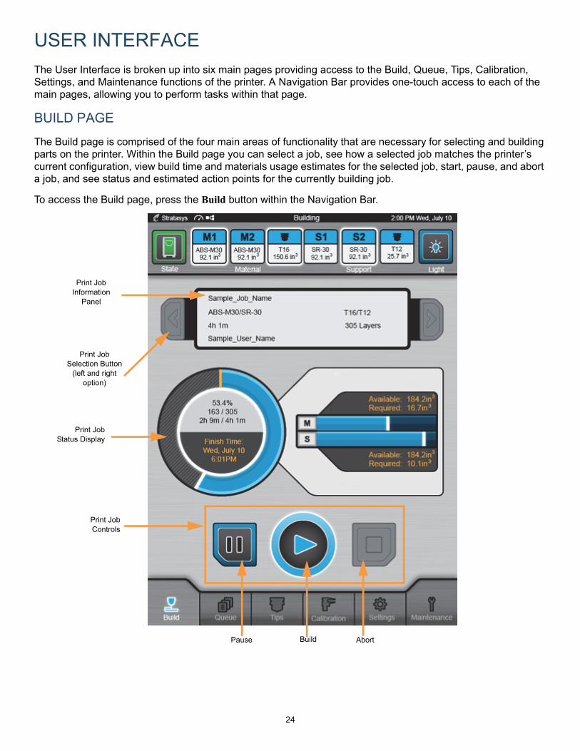
The Build page is comprised of the four main areas of functionality that are necessary for selecting and building parts on the printer. Within the Build page you can select a job, see how a selected job matches the printer’s current configuration, view build time and materials usage estimates for the selected job, start, pause, and abort a job, and see status and estimated action points for the currently building job.
To access the Build page, press the Build button within the Navigation Bar.
Print JobInformation
Panel
Print JobStatus Display
Print JobSelection Button
(left and right option)
Print JobControls
Pause Build Abort
25
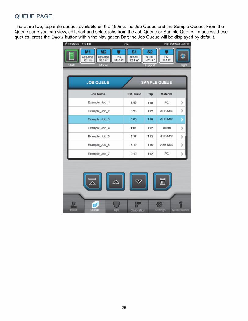
QUEUE PAGE
There are two, separate queues available on the 450mc: the Job Queue and the Sample Queue. From the Queue page you can view, edit, sort and select jobs from the Job Queue or Sample Queue. To access these queues, press the Queue button within the Navigation Bar; the Job Queue will be displayed by default.

26
TIPS PAGE
The Tips page displays a detailed representation of the printer’s current materials and tips configuration. Two Tip Status Icons and four Material Status Icons (similar to the icons within the Dashboard) represent the tips and model/support materials loaded/installed within the printer. These icons will take on a variety of colors and highlighted states depending on their status.
Within this page you can view the current configuration of the printer including model and support tip size and odometer values, current and set point tip temperatures and model and support material types, view canister volumes and load statuses, load and unload materials, access the Tip Change Wizard and Tip Wipe Adjust Wizard, and perform a variety of tip maintenance functions.
To access the Tips page, press the Tips button within the Navigation Bar.
Tip Status Icons
Material Load Controls
Material Status Icons
Canister Load Status
Cancel Material Load/Unload Button
Tip Change Tip Maintenance Tip Control

27
CALIBRATION PAGE
The Calibration page allows you to perform a variety of calibration procedures on the printer, including:
• XYZ Tip Offset Calibration• Touchscreen Calibration• Find XY Home • Find Z Home
To access the Calibration page, press the Calibration button within the Navigation Bar.
Calibration Control Buttons
Calibration Status Pane
XYZ Tip Offset Calibration
Touchscreen Calibration
Z Homing XY Homing
28
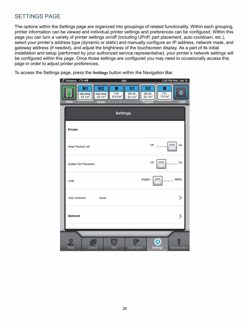
SETTINGS PAGE
The options within the Settings page are organized into groupings of related functionality. Within each grouping, printer information can be viewed and individual printer settings and preferences can be configured. Within this page you can turn a variety of printer settings on/off (including UPnP, part placement, auto cooldown, etc.), select your printer’s address type (dynamic or static) and manually configure an IP address, network mask, and gateway address (if needed), and adjust the brightness of the touchscreen display. As a part of its initial installation and setup (performed by your authorized service representative), your printer’s network settings will be configured within this page. Once those settings are configured you may need to occasionally access this page in order to adjust printer preferences.
To access the Settings page, press the Settings button within the Navigation Bar.
29
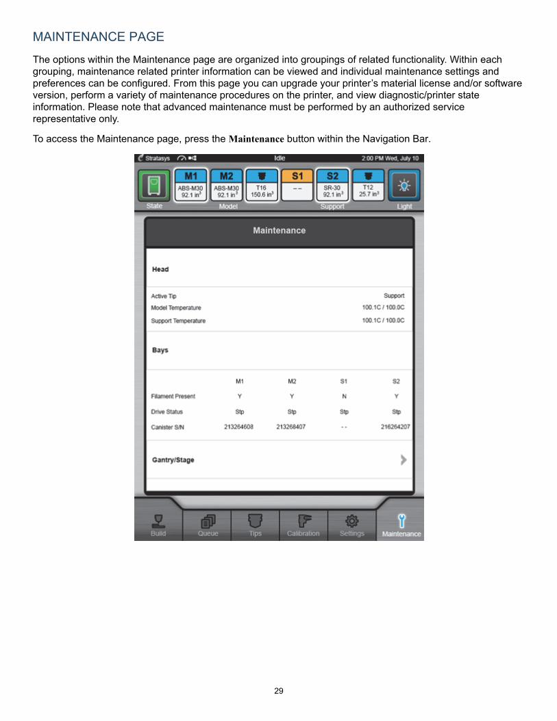
MAINTENANCE PAGE
The options within the Maintenance page are organized into groupings of related functionality. Within each grouping, maintenance related printer information can be viewed and individual maintenance settings and preferences can be configured. From this page you can upgrade your printer’s material license and/or software version, perform a variety of maintenance procedures on the printer, and view diagnostic/printer state information. Please note that advanced maintenance must be performed by an authorized service representative only.
To access the Maintenance page, press the Maintenance button within the Navigation Bar.
30
LOADING/UNLOADING MATERIAL
LOADING MATERIAL TO THE LIQUEFIER TIPS
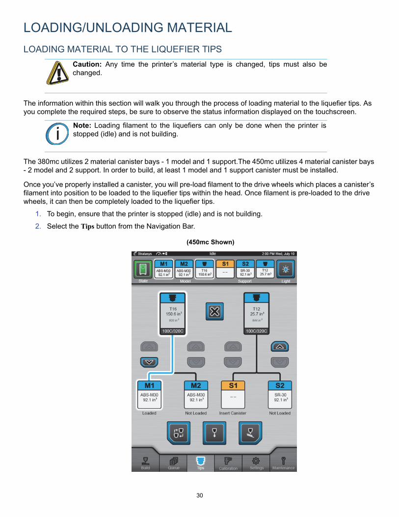
The information within this section will walk you through the process of loading material to the liquefier tips. As you complete the required steps, be sure to observe the status information displayed on the touchscreen.
The 380mc utilizes 2 material canister bays - 1 model and 1 support.The 450mc utilizes 4 material canister bays - 2 model and 2 support. In order to build, at least 1 model and 1 support canister must be installed.
Once you’ve properly installed a canister, you will pre-load filament to the drive wheels which places a canister’s filament into position to be loaded to the liquefier tips within the head. Once filament is pre-loaded to the drive wheels, it can then be completely loaded to the liquefier tips.
1. To begin, ensure that the printer is stopped (idle) and is not building.
2. Select the Tips button from the Navigation Bar.
Caution: Any time the printer’s material type is changed, tips must also bechanged.
Note: Loading filament to the liquefiers can only be done when the printer isstopped (idle) and is not building.
(450mc Shown)
31
3. Observe the status information displayed below each of the model and support canister icons. The "Insert Canister" status indicates that a canister is not present in the material’s corresponding canister bay.
4. Insert a material canister into its appropriate material bay and lower the canister drive.
5. Feed filament into the cannister drive by pressing in and down on the canister’s thumbwheel. Turn the thumbwheel until you feel the drive motor pull the filament and the canister status LED begins to flash green.
6. The printer automatically completes the process of pre-loading filament.
• The canister advances filament until it contacts the filament present sensor. Once filament is detected, the drive motor stops and the canister status LED begins to flash green.
• A status of "Advance Filament" is displayed until filament is detected by the filament present sensor. Once filament is detected, status is updated to "Not Loaded".
• Close the canister’s thumbwheel door.
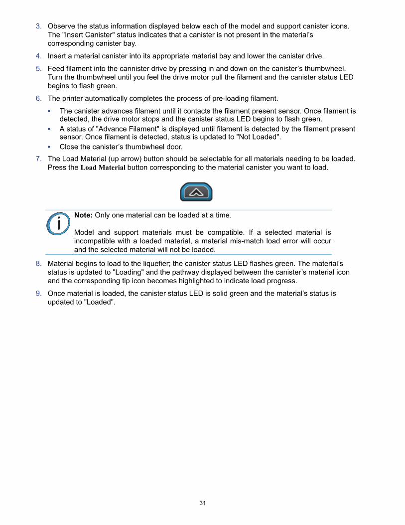
7. The Load Material (up arrow) button should be selectable for all materials needing to be loaded. Press the Load Material button corresponding to the material canister you want to load.
8. Material begins to load to the liquefier; the canister status LED flashes green. The material’s status is updated to "Loading" and the pathway displayed between the canister’s material icon and the corresponding tip icon becomes highlighted to indicate load progress.
9. Once material is loaded, the canister status LED is solid green and the material’s status is updated to "Loaded".
Note: Only one material can be loaded at a time.
Model and support materials must be compatible. If a selected material isincompatible with a loaded material, a material mis-match load error will occurand the selected material will not be loaded.
32
UNLOADING MATERIAL FROM THE LIQUEFIER TIPS
Perform the following steps to unload material from the liquefier tips:
1. Ensure that the printer is stopped (idle) and is not building.
2. Select the Tips button from the Navigation Bar. The information displayed represents the current configuration of your printer.
3. Observe the status information displayed below each of the model and support canister option icons. A "Loaded" status indicates currently loaded material.
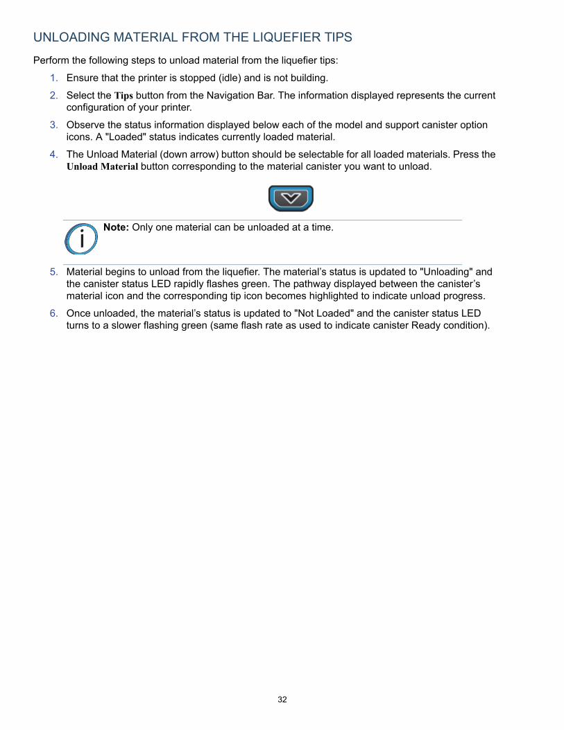
4. The Unload Material (down arrow) button should be selectable for all loaded materials. Press the Unload Material button corresponding to the material canister you want to unload.
5. Material begins to unload from the liquefier. The material’s status is updated to "Unloading" and the canister status LED rapidly flashes green. The pathway displayed between the canister’s material icon and the corresponding tip icon becomes highlighted to indicate unload progress.
6. Once unloaded, the material’s status is updated to "Not Loaded" and the canister status LED turns to a slower flashing green (same flash rate as used to indicate canister Ready condition).
Note: Only one material can be unloaded at a time.
33
CHANGING TIPS OR MATERIAL TYPE
The information within this section is meant to guide you through the process of changing materials and tips. The Tips page includes a Tip Change Wizard designed to streamline the process of changing the printer’s model and/or support materials and tips.
Whenever the printer’s material type is changed, tips must also be changed. The Tip Change Wizard contains a step which will instruct you to change tips when necessary.
After changing one or both tips and exiting the wizard, you must manually adjust tip wipe heights to ensure proper placement of the printer’s flicker/brush assemblies in relation to tips/tip shields. The final page of the wizard will prompt you to perform this adjustment.
USING THE TIP CHANGE WIZARD
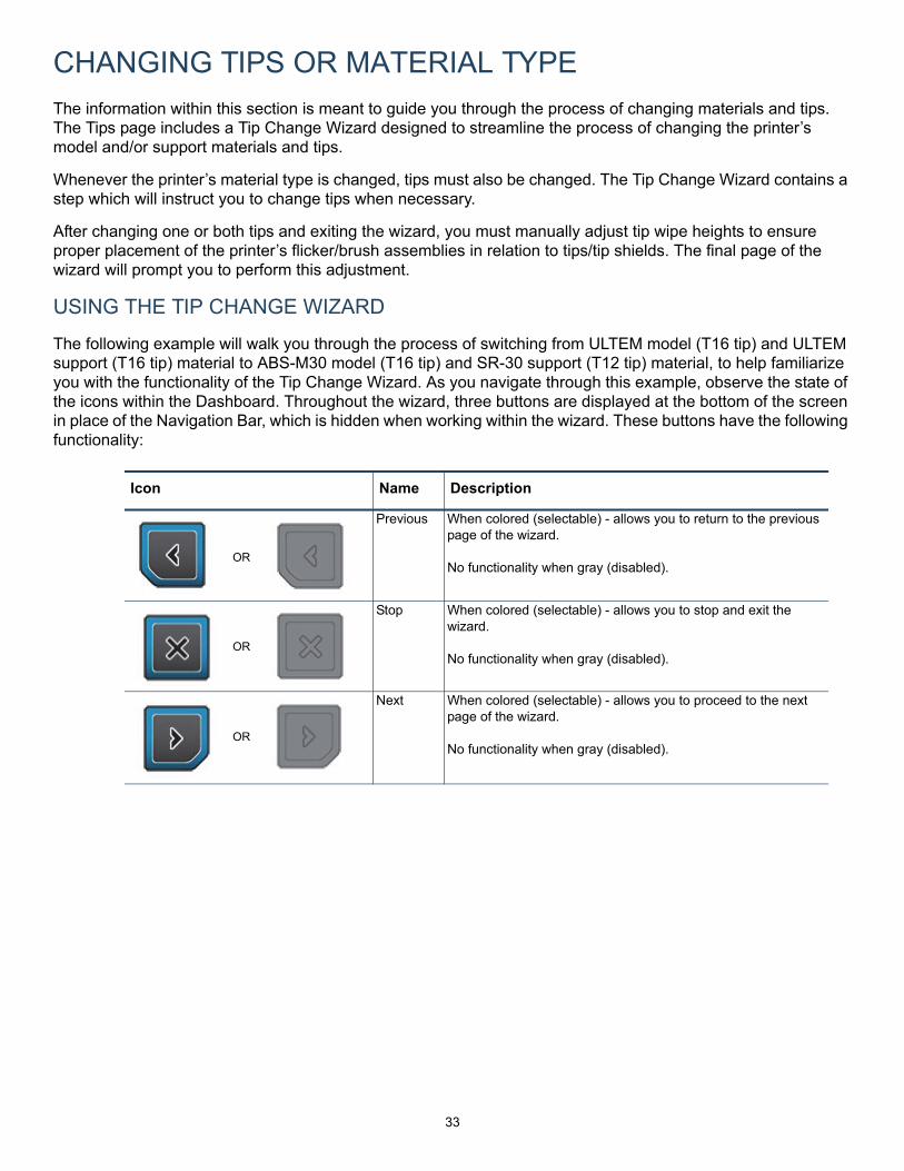
The following example will walk you through the process of switching from ULTEM model (T16 tip) and ULTEM support (T16 tip) material to ABS-M30 model (T16 tip) and SR-30 support (T12 tip) material, to help familiarize you with the functionality of the Tip Change Wizard. As you navigate through this example, observe the state of the icons within the Dashboard. Throughout the wizard, three buttons are displayed at the bottom of the screen in place of the Navigation Bar, which is hidden when working within the wizard. These buttons have the following functionality:
Icon Name Description
Previous When colored (selectable) - allows you to return to the previous page of the wizard.
No functionality when gray (disabled).
Stop When colored (selectable) - allows you to stop and exit the wizard.
No functionality when gray (disabled).
Next When colored (selectable) - allows you to proceed to the next page of the wizard.
No functionality when gray (disabled).
OR
OR
OR
34
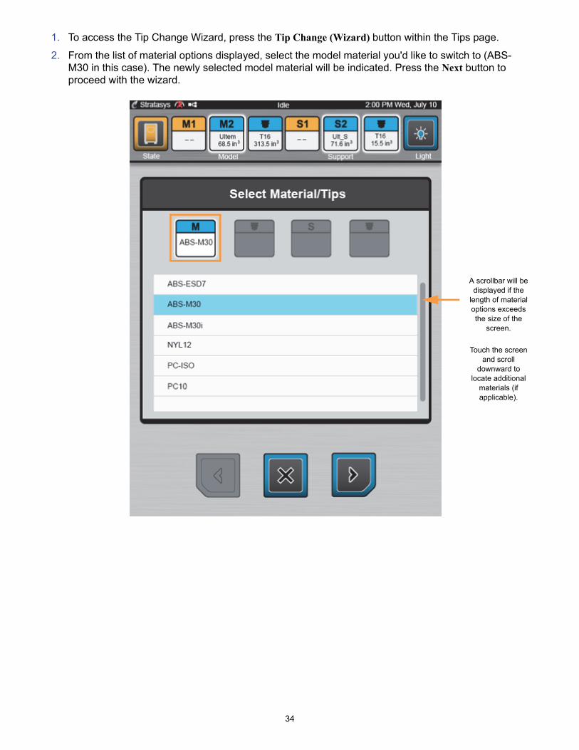
1. To access the Tip Change Wizard, press the Tip Change (Wizard) button within the Tips page.
2. From the list of material options displayed, select the model material you'd like to switch to (ABS-M30 in this case). The newly selected model material will be indicated. Press the Next button to proceed with the wizard.
A scrollbar will be displayed if the
length of material options exceeds the size of the
screen.
Touch the screen and scroll
downward to locate additional
materials (if applicable).

35
3. From the list of tip options displayed, select the model tip you'd like to switch to (T16 (new) in this case). The newly selected model tip will be indicated. Press the Next button to proceed with the wizard.
Note: When selecting the tip you’d like to switch to you are given a "current"(i.e. T16 (current)) and "new" (i.e. T16 (new)) option for the tip size currentlyinstalled in the printer (if applicable). If the currently installed tip is compatiblewith the material type you’re switching to you can reuse the tip; however, youmay only reuse one tip. For example, if you choose to reuse the currentlyinstalled model tip (i.e. selecting T16(current) below) you must select a newsupport tip in step 5.

36
4. Based on the model material you selected in step 2, a list of support material options will be displayed. From the list of material options displayed, select the support material you'd like to switch to (SR-30 in this case).
In this case, only one material option is displayed (and is selected by default) as only one support material is compatible with the model material selected previously. Press the Next button to proceed with the wizard.

37
5. Based on the support material you selected in the previous step, a list of compatible support tip options will be displayed. From the list of support tip options displayed select the support tip you'd like to switch to (T12 in this case). In this case, only one support tip option (T12) is displayed, and is selected by default, as only one support tip is compatible with the support material selected previously. Press the Next button to proceed with the wizard.
Note: When selecting the tip you’d like to switch to you are given a "current"(i.e. T16 (current)) and "new" (i.e. T16 (new)) option for the tip size currentlyinstalled in the printer (if applicable). If the currently installed tip is compatiblewith the material type you’re switching to you can reuse the tip; however, youmay only reuse one tip. For example, if you chose to reuse the currently installedmodel tip in step 5 you must select a new support tip.
38
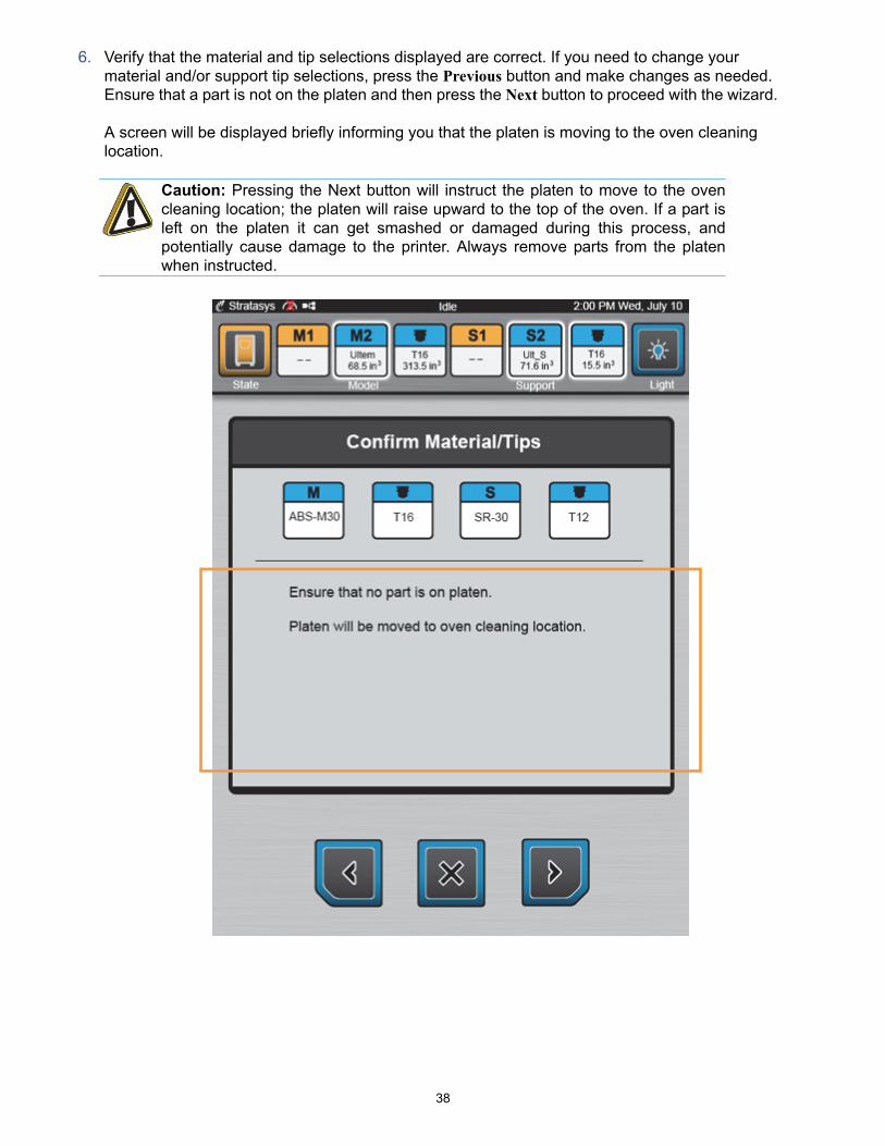
6. Verify that the material and tip selections displayed are correct. If you need to change your material and/or support tip selections, press the Previous button and make changes as needed. Ensure that a part is not on the platen and then press the Next button to proceed with the wizard.
A screen will be displayed briefly informing you that the platen is moving to the oven cleaning location.
Caution: Pressing the Next button will instruct the platen to move to the ovencleaning location; the platen will raise upward to the top of the oven. If a part isleft on the platen it can get smashed or damaged during this process, andpotentially cause damage to the printer. Always remove parts from the platenwhen instructed.
39
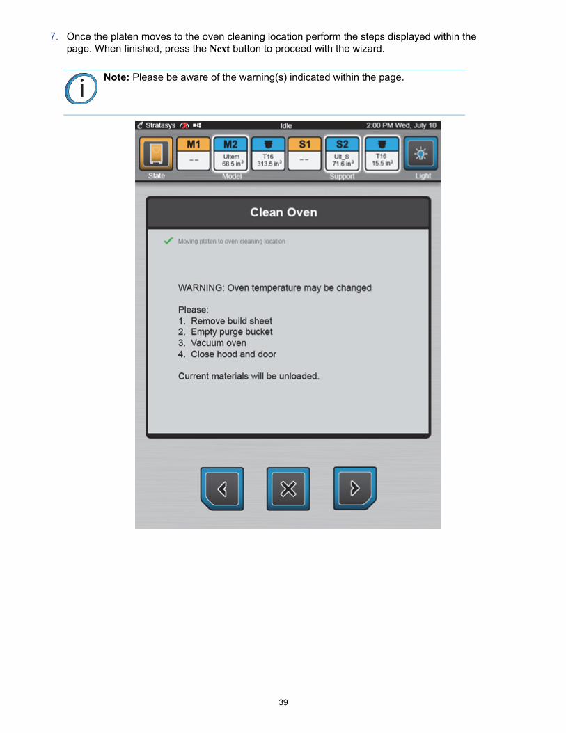
7. Once the platen moves to the oven cleaning location perform the steps displayed within the page. When finished, press the Next button to proceed with the wizard.
Note: Please be aware of the warning(s) indicated within the page.
40
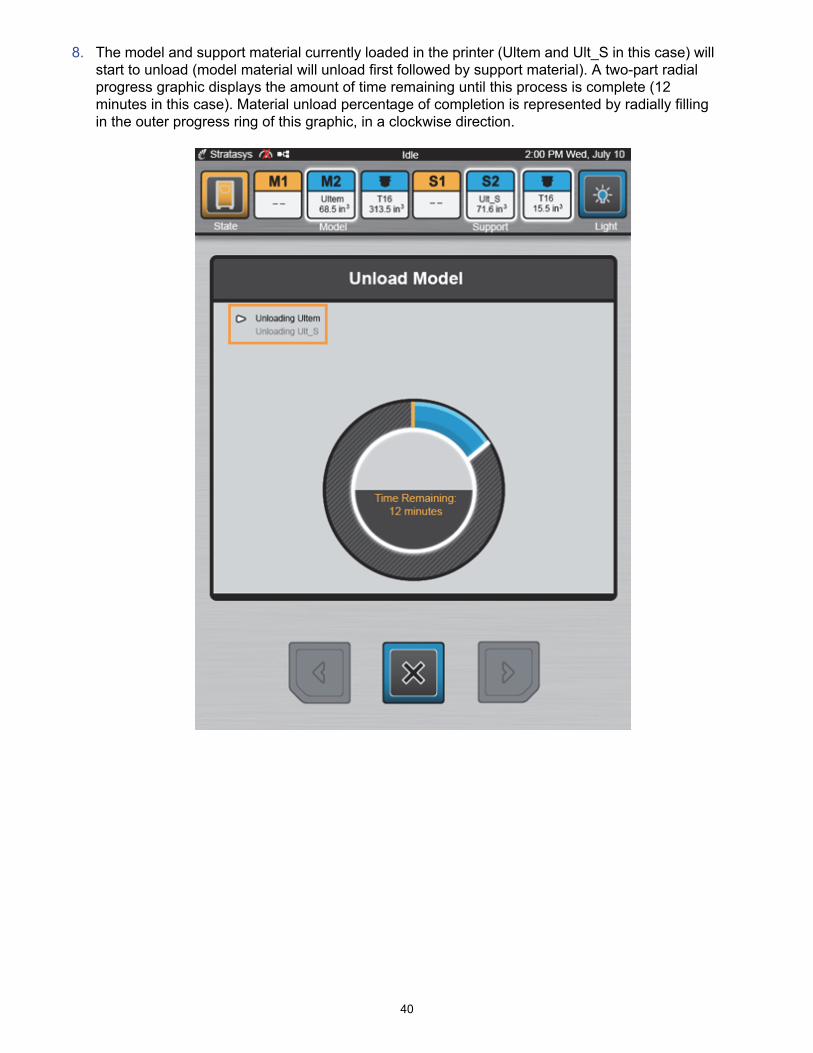
8. The model and support material currently loaded in the printer (Ultem and Ult_S in this case) will start to unload (model material will unload first followed by support material). A two-part radial progress graphic displays the amount of time remaining until this process is complete (12 minutes in this case). Material unload percentage of completion is represented by radially filling in the outer progress ring of this graphic, in a clockwise direction.
41
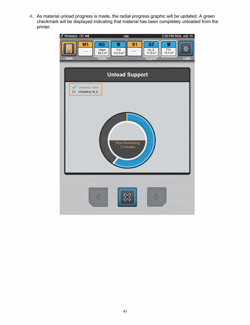
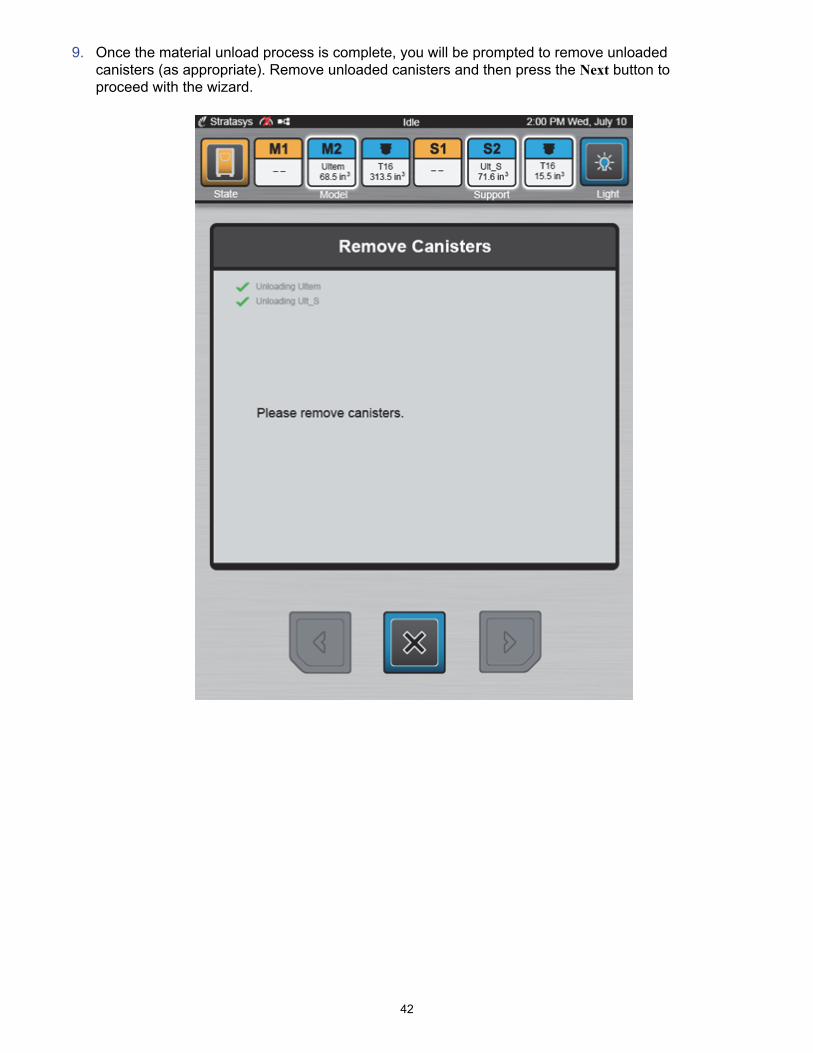
A. As material unload progress is made, the radial progress graphic will be updated. A green checkmark will be displayed indicating that material has been completely unloaded from the printer.
42
9. Once the material unload process is complete, you will be prompted to remove unloaded canisters (as appropriate). Remove unloaded canisters and then press the Next button to proceed with the wizard.

43
Once canisters have been removed, the printer will clear the filament remaining within the filament tubes. Excess material accumulates in the empty canister bay; discard this material and then press the Next button to proceed with the wizard.
Caution: Discard material pulled from printer. Do not attempt to rewind materialin canister. If filament is forced into canister, cross winding will most likely occur,making the entire canister unusable.
Note: The Material Status Icons for the unloaded canisters will update to reflecttheir now empty state.

44
1. Confirm that the material and tip selections displayed are correct and then press the Next button to proceed with the wizard.
Note: Please be aware of the warnings associated with your selections. A tipand/or material type change will require calibration. If you proceed past thispage of the wizard and exit the wizard without performing an XYZ Tip OffsetCalibration, your printer will not be calibrated. You will not be able to build partsuntil you calibrate the printer by performing an XYZ Tip Offset Calibration.
Note: If the printer’s head is not currently in the Service Location, a screen willbe displayed briefly informing you that the head is moving to the ServiceLocation.

45
2. A screen will be displayed momentarily indicating that the printer is preparing to have its tip(s) replaced. Perform the necessary steps to replace model and/or support tips.
If a tip is removed that may be re-installed at a later time, be sure to record the tip’s odometer reading (item 4 in the image below) and store this reading with the removed tip. Once a new model and/or support tip is installed, press the Next button to proceed with the wizard.
46
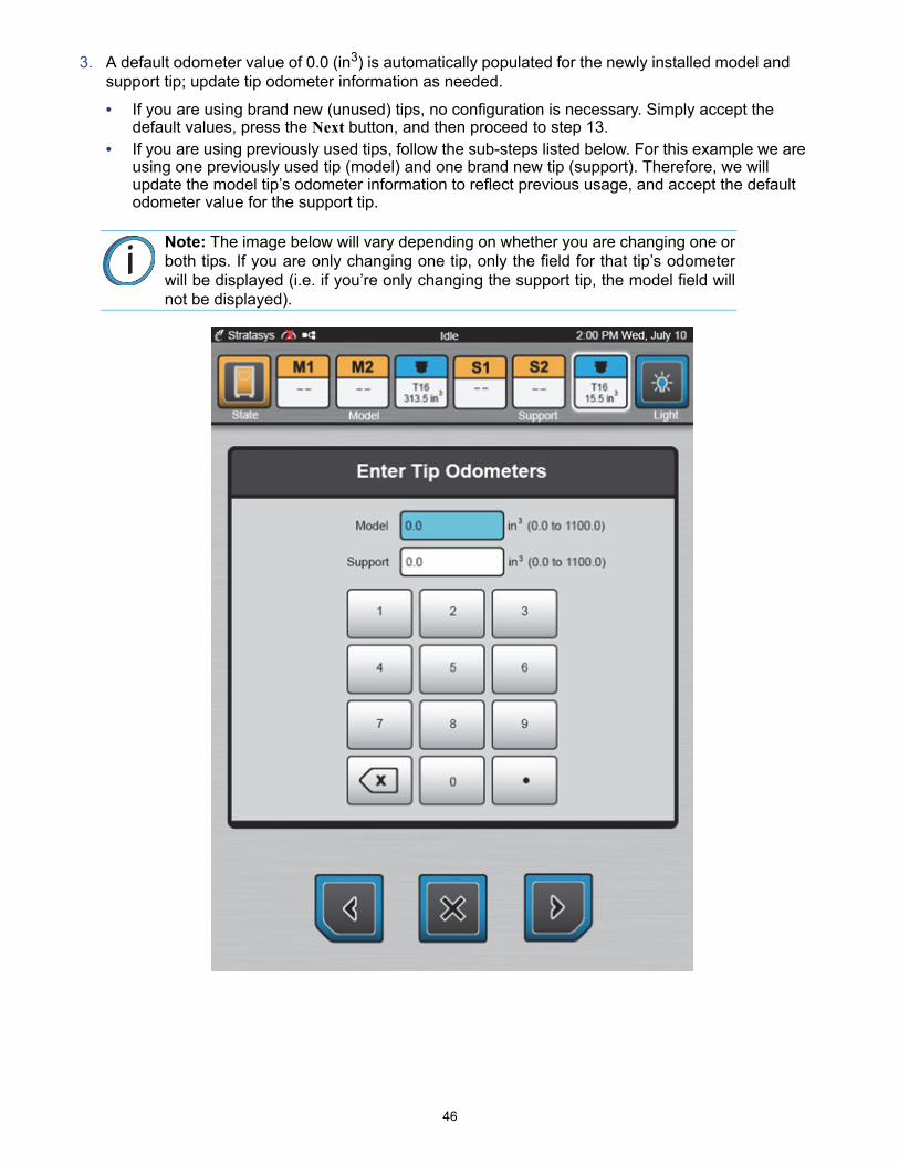
3. A default odometer value of 0.0 (in3) is automatically populated for the newly installed model and support tip; update tip odometer information as needed.
• If you are using brand new (unused) tips, no configuration is necessary. Simply accept the default values, press the Next button, and then proceed to step 13.
• If you are using previously used tips, follow the sub-steps listed below. For this example we are using one previously used tip (model) and one brand new tip (support). Therefore, we will update the model tip’s odometer information to reflect previous usage, and accept the default odometer value for the support tip.
Note: The image below will vary depending on whether you are changing one orboth tips. If you are only changing one tip, only the field for that tip’s odometerwill be displayed (i.e. if you’re only changing the support tip, the model field willnot be displayed).

47
A. Press the touchscreen anywhere within the Model field. When selected, the field will turn blue.
B. Using the keypad, enter the odometer value corresponding to your model tip
(150.6 in3 in this case). Use the delete key to erase a field’s default value.
C. Repeat steps A and B as needed to update the support tip's odometer information. For this
example, we will accept the default value of 0.0 (in3).
D. Confirm that the tip odometer information you entered is correct and then press the Next button to proceed with the wizard.
Note: Depending on the printer’s current oven temperature, oven temperaturemay need to stabilize following this step.
Delete Key
48
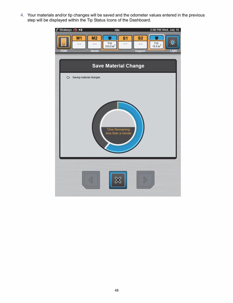
4. Your materials and/or tip changes will be saved and the odometer values entered in the previous step will be displayed within the Tip Status Icons of the Dashboard.
49
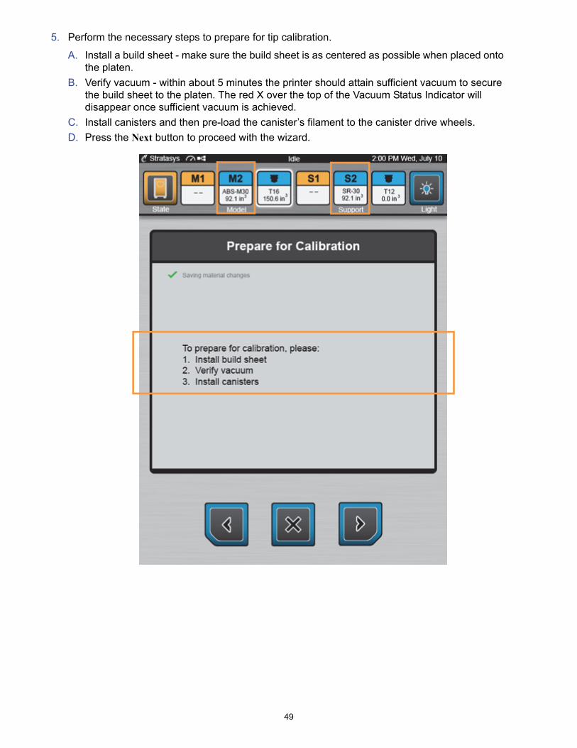
5. Perform the necessary steps to prepare for tip calibration.
A. Install a build sheet - make sure the build sheet is as centered as possible when placed onto the platen.
B. Verify vacuum - within about 5 minutes the printer should attain sufficient vacuum to secure the build sheet to the platen. The red X over the top of the Vacuum Status Indicator will disappear once sufficient vacuum is achieved.
C. Install canisters and then pre-load the canister’s filament to the canister drive wheels.
D. Press the Next button to proceed with the wizard.

50
6. Select the model and support canisters to be loaded during the calibration sequence (M2 and S2 in this case) by pressing the corresponding row on the touchscreen. When selected, the row will be blue. Selected canisters are indicated by a white outline encasing the canister's icon. Canisters with the lowest volume of material are selected by default. If only one model and one support canister are installed, those canisters are selected by default. Press the Next button to proceed with the wizard.
51
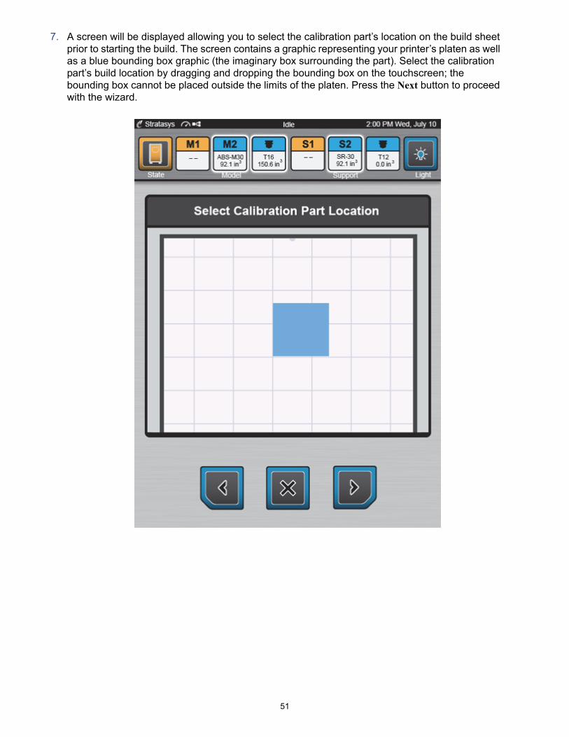
7. A screen will be displayed allowing you to select the calibration part’s location on the build sheet prior to starting the build. The screen contains a graphic representing your printer’s platen as well as a blue bounding box graphic (the imaginary box surrounding the part). Select the calibration part’s build location by dragging and dropping the bounding box on the touchscreen; the bounding box cannot be placed outside the limits of the platen. Press the Next button to proceed with the wizard.

52
8. The printer will begin the process of building a calibration part. This process includes allowing oven temperature to stabilize, performing a Z tip-to-tip calibration, loading model material, loading support material, and then building the calibration part. The status of each task is indicated on the screen. A green checkmark will be displayed once a task is completed and the page’s header will update to reflect the task currently in process.
A two-part radial progress graphic is displayed within the center of the page. This graphic displays the amount of time remaining until the entire process is complete (18 minutes in this case). Completion percentage is represented by radially filling in the outer progress ring of this graphic, in a clockwise direction. As each task is completed, the progress graphic will be updated.
Name of task in
process
Tasks to complete

53
A. The screen will update as the printer:
• Performs a Z tip-to-tip calibration.
54
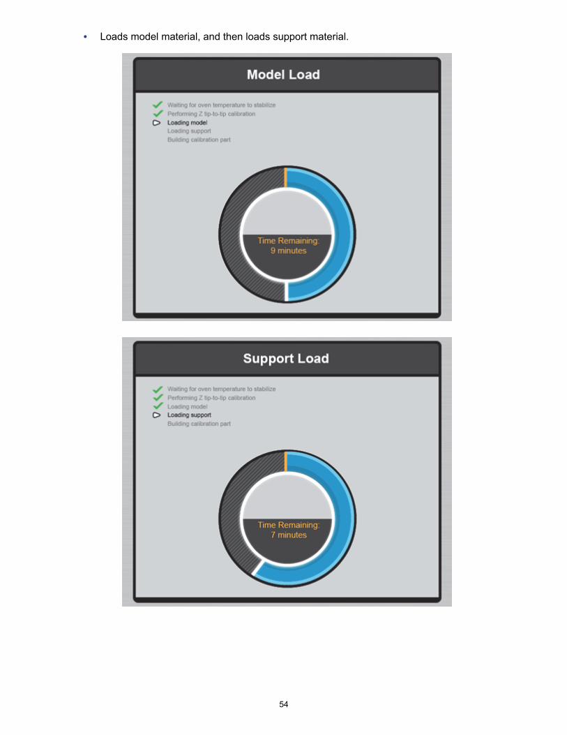
• Loads model material, and then loads support material.
55
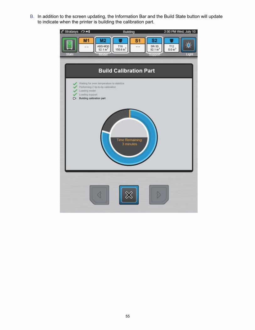
B. In addition to the screen updating, the Information Bar and the Build State button will update to indicate when the printer is building the calibration part.

56
C. Once the calibration part is complete you will be prompted to remove the part from the printer. Remove the completed part and then press the Next button to proceed with the wizard.
57
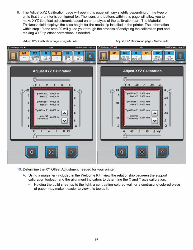
9. The Adjust XYZ Calibration page will open; this page will vary slightly depending on the type of units that the printer is configured for. The icons and buttons within this page will allow you to make XYZ tip offset adjustments based on an analysis of the calibration part. The Material Thickness field displays the slice height for the model tip installed in the printer. The information within step 19 and step 20 will guide you through the process of analyzing the calibration part and making XYZ tip offset corrections, if needed.
10. Determine the XY Offset Adjustment needed for your printer.
A. Using a magnifier (included in the Welcome Kit), view the relationship between the support calibration toolpath and the alignment indicators to determine the X and Y axis calibration.
• Holding the build sheet up to the light, a contrasting-colored wall, or a contrasting-colored piece of paper may make it easier to view this toolpath.
Adjust XYZ Calibration page - English units Adjust XYZ Calibration page - Metric units

58
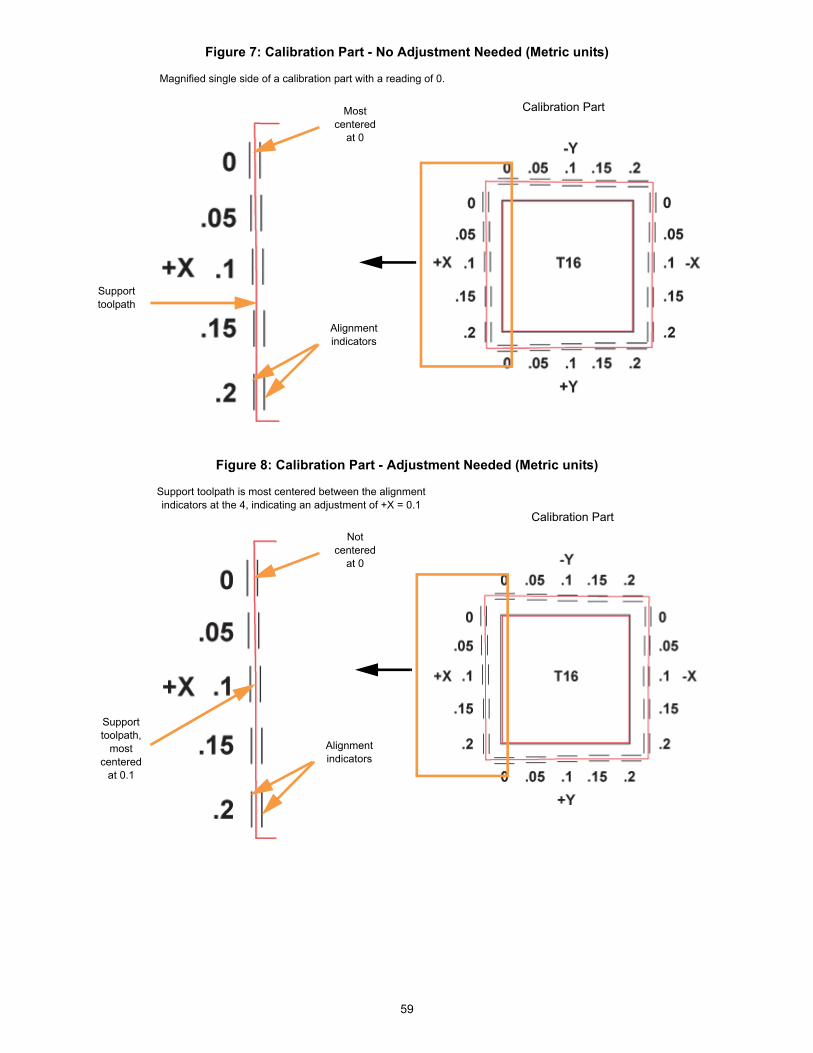
B. Determine where on each axis the support toolpath is most centered between the X-Y alignment indicators (see Figure 5 and Figure 6 for English units, and Figure 7 and Figure 8 for Metric units). The numbers on the calibration part represent thousandths of an inch (e.g., 4 = 0.004 in. (0.1mm)).
Figure 5: Calibration Part - No Adjustment Needed (English units)
Figure 6: Calibration Part - Adjustment Needed (English units)
Calibration Part
Alignment indicators
Support toolpath
Magnified single side of a calibration part with a reading of 0.
Most centered
at 0
Calibration Part
Support toolpath,
most centered
at 4
Not centered
at 0
Support toolpath is most centered between the alignment indicators at the 4, indicating an adjustment of +X = 0.004
Alignment indicators
59
Figure 7: Calibration Part - No Adjustment Needed (Metric units)
Figure 8: Calibration Part - Adjustment Needed (Metric units)
Calibration Part
Alignment indicators
Support toolpath
Magnified single side of a calibration part with a reading of 0.
Most centered
at 0
Calibration Part
Support toolpath,
most centered
at 0.1
Not centered
at 0
Support toolpath is most centered between the alignment indicators at the 4, indicating an adjustment of +X = 0.1
Alignment indicators
60
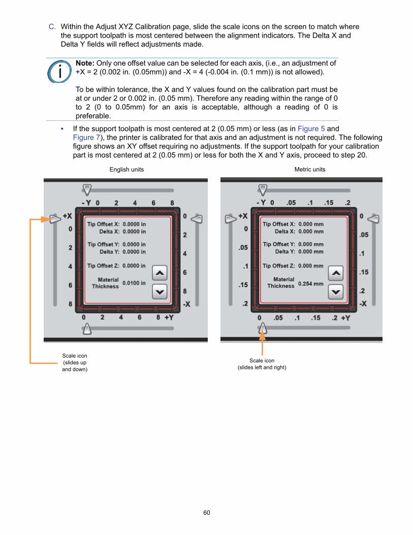
C. Within the Adjust XYZ Calibration page, slide the scale icons on the screen to match where the support toolpath is most centered between the alignment indicators. The Delta X and Delta Y fields will reflect adjustments made.
• If the support toolpath is most centered at 2 (0.05 mm) or less (as in Figure 5 and Figure 7), the printer is calibrated for that axis and an adjustment is not required. The following figure shows an XY offset requiring no adjustments. If the support toolpath for your calibration part is most centered at 2 (0.05 mm) or less for both the X and Y axis, proceed to step 20.
Note: Only one offset value can be selected for each axis, (i.e., an adjustment of +X = 2 (0.002 in. (0.05mm)) and -X = 4 (-0.004 in. (0.1 mm)) is not allowed).
To be within tolerance, the X and Y values found on the calibration part must beat or under 2 or 0.002 in. (0.05 mm). Therefore any reading within the range of 0to 2 (0 to 0.05mm) for an axis is acceptable, although a reading of 0 ispreferable.
English units Metric units
Scale icon (slides up and down)
Scale icon (slides left and right)
61
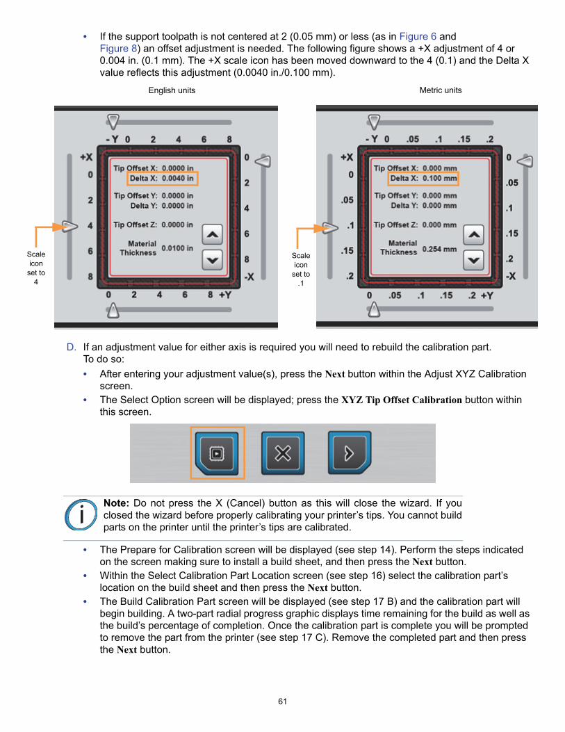
• If the support toolpath is not centered at 2 (0.05 mm) or less (as in Figure 6 and Figure 8) an offset adjustment is needed. The following figure shows a +X adjustment of 4 or 0.004 in. (0.1 mm). The +X scale icon has been moved downward to the 4 (0.1) and the Delta X value reflects this adjustment (0.0040 in./0.100 mm).
D. If an adjustment value for either axis is required you will need to rebuild the calibration part. To do so:
• After entering your adjustment value(s), press the Next button within the Adjust XYZ Calibration screen.
• The Select Option screen will be displayed; press the XYZ Tip Offset Calibration button within this screen.
• The Prepare for Calibration screen will be displayed (see step 14). Perform the steps indicated on the screen making sure to install a build sheet, and then press the Next button.
• Within the Select Calibration Part Location screen (see step 16) select the calibration part’s location on the build sheet and then press the Next button.
• The Build Calibration Part screen will be displayed (see step 17 B) and the calibration part will begin building. A two-part radial progress graphic displays time remaining for the build as well as the build’s percentage of completion. Once the calibration part is complete you will be prompted to remove the part from the printer (see step 17 C). Remove the completed part and then press the Next button.
Note: Do not press the X (Cancel) button as this will close the wizard. If youclosed the wizard before properly calibrating your printer’s tips. You cannot buildparts on the printer until the printer’s tips are calibrated.
Scale icon
set to 4
Scale icon
set to .1
English units Metric units
62
• Repeat the instructions in step 19. Continue to check and adjust for XY offset. Readjusting until the calibration toolpath is centered at 0 for the X and Y axis is preferable. However, readjusting until the calibration toolpath for X and Y is within tolerance, which is at or under 2 or 0.002 in. (0.05 mm) for an axis, is acceptable.
E. Proceed to the Z offset adjustment (step 20) once the calibration toolpath for X and Y is within tolerance.
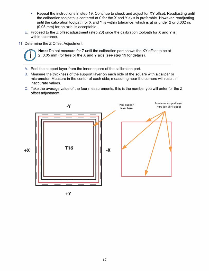
11. Determine the Z Offset Adjustment.
A. Peel the support layer from the inner square of the calibration part.
B. Measure the thickness of the support layer on each side of the square with a caliper or micrometer. Measure in the center of each side; measuring near the corners will result in inaccurate values.
C. Take the average value of the four measurements; this is the number you will enter for the Z offset adjustment.
Note: Do not measure for Z until the calibration part shows the XY offset to be at2 (0.05 mm) for less or the X and Y axis (see step 19 for details).
Peel support layer here
Measure support layerhere (on all 4 sides)
63
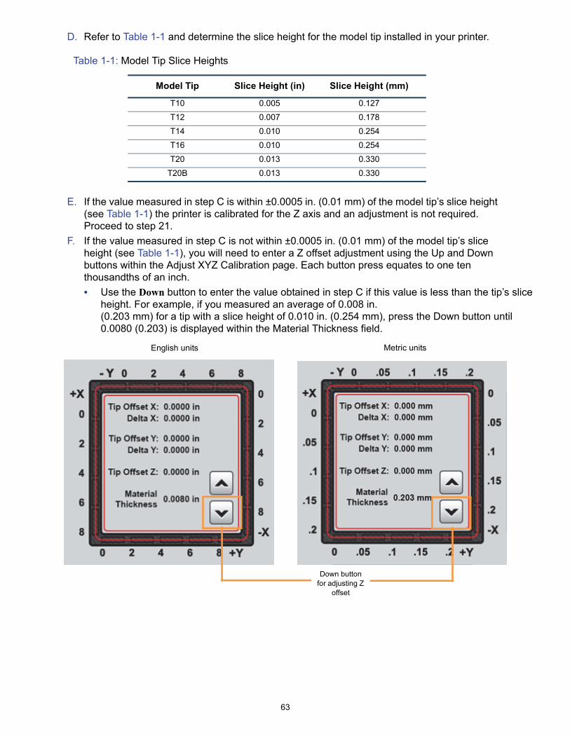
D. Refer to Table 1-1 and determine the slice height for the model tip installed in your printer.
Table 1-1: Model Tip Slice Heights
E. If the value measured in step C is within ±0.0005 in. (0.01 mm) of the model tip’s slice height (see Table 1-1) the printer is calibrated for the Z axis and an adjustment is not required. Proceed to step 21.
F. If the value measured in step C is not within ±0.0005 in. (0.01 mm) of the model tip’s slice height (see Table 1-1), you will need to enter a Z offset adjustment using the Up and Down buttons within the Adjust XYZ Calibration page. Each button press equates to one ten thousandths of an inch.
• Use the Down button to enter the value obtained in step C if this value is less than the tip’s slice height. For example, if you measured an average of 0.008 in. (0.203 mm) for a tip with a slice height of 0.010 in. (0.254 mm), press the Down button until 0.0080 (0.203) is displayed within the Material Thickness field.
Model Tip Slice Height (in) Slice Height (mm)
T10 0.005 0.127
T12 0.007 0.178
T14 0.010 0.254
T16 0.010 0.254
T20 0.013 0.330
T20B 0.013 0.330
Down button for adjusting Z
offset
English units Metric units
64
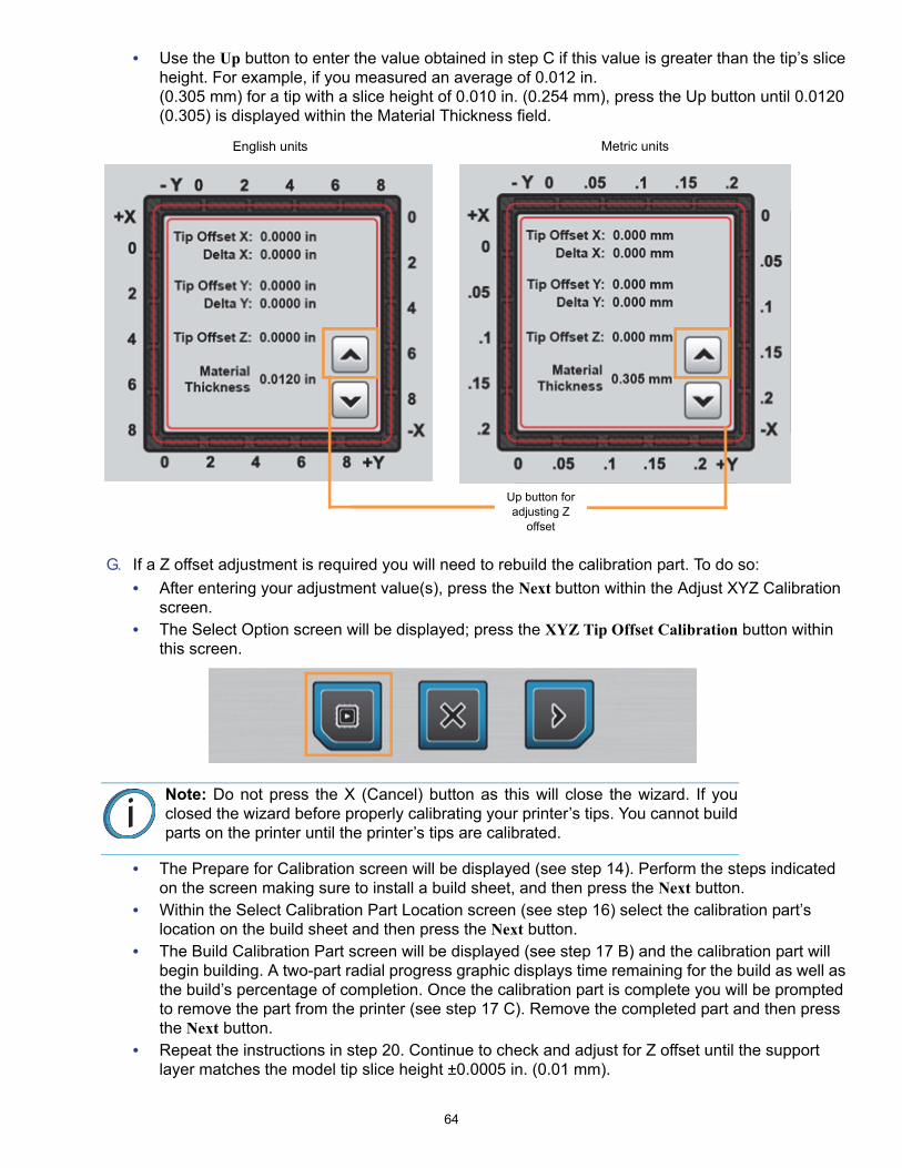
• Use the Up button to enter the value obtained in step C if this value is greater than the tip’s slice height. For example, if you measured an average of 0.012 in. (0.305 mm) for a tip with a slice height of 0.010 in. (0.254 mm), press the Up button until 0.0120 (0.305) is displayed within the Material Thickness field.
G. If a Z offset adjustment is required you will need to rebuild the calibration part. To do so:
• After entering your adjustment value(s), press the Next button within the Adjust XYZ Calibration screen.
• The Select Option screen will be displayed; press the XYZ Tip Offset Calibration button within this screen.
• The Prepare for Calibration screen will be displayed (see step 14). Perform the steps indicated on the screen making sure to install a build sheet, and then press the Next button.
• Within the Select Calibration Part Location screen (see step 16) select the calibration part’s location on the build sheet and then press the Next button.
• The Build Calibration Part screen will be displayed (see step 17 B) and the calibration part will begin building. A two-part radial progress graphic displays time remaining for the build as well as the build’s percentage of completion. Once the calibration part is complete you will be prompted to remove the part from the printer (see step 17 C). Remove the completed part and then press the Next button.
• Repeat the instructions in step 20. Continue to check and adjust for Z offset until the support layer matches the model tip slice height ±0.0005 in. (0.01 mm).
Note: Do not press the X (Cancel) button as this will close the wizard. If youclosed the wizard before properly calibrating your printer’s tips. You cannot buildparts on the printer until the printer’s tips are calibrated.
English units Metric units
Up button for adjusting Z
offset
65
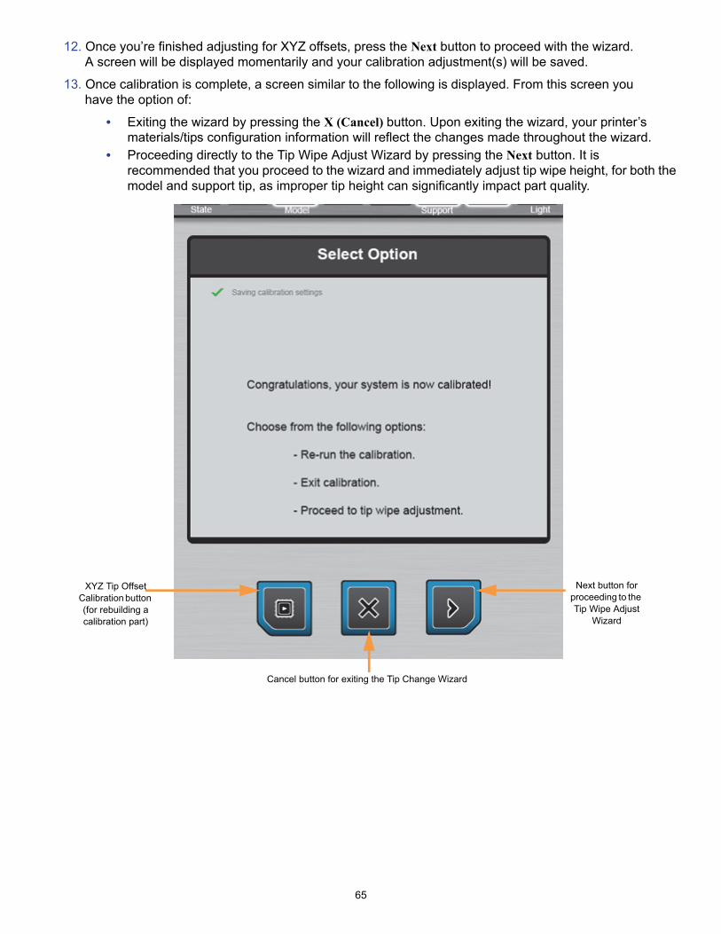
12. Once you’re finished adjusting for XYZ offsets, press the Next button to proceed with the wizard. A screen will be displayed momentarily and your calibration adjustment(s) will be saved.
13. Once calibration is complete, a screen similar to the following is displayed. From this screen you have the option of:
• Exiting the wizard by pressing the X (Cancel) button. Upon exiting the wizard, your printer’s materials/tips configuration information will reflect the changes made throughout the wizard.
• Proceeding directly to the Tip Wipe Adjust Wizard by pressing the Next button. It is recommended that you proceed to the wizard and immediately adjust tip wipe height, for both the model and support tip, as improper tip height can significantly impact part quality.
XYZ Tip Offset Calibration button (for rebuilding a calibration part)
Next button for proceeding to the Tip Wipe Adjust
Wizard
Cancel button for exiting the Tip Change Wizard

66
CHANGING TIPS
Any time the printer’s material type is changed, tips must also be changed. If you are following the steps outlined in the Tip Change Wizard, complete the steps below to change tips.
1. Open the top cover.
2. Place the head in the head maintenance bracket.
Warning: Always use an approved ladder or step stool when working withcomponents under the top cover.
Gloves: Liquefier tips can be hot. You must wear safety gloves (provided in theWelcome Kit) when replacing tips.
67
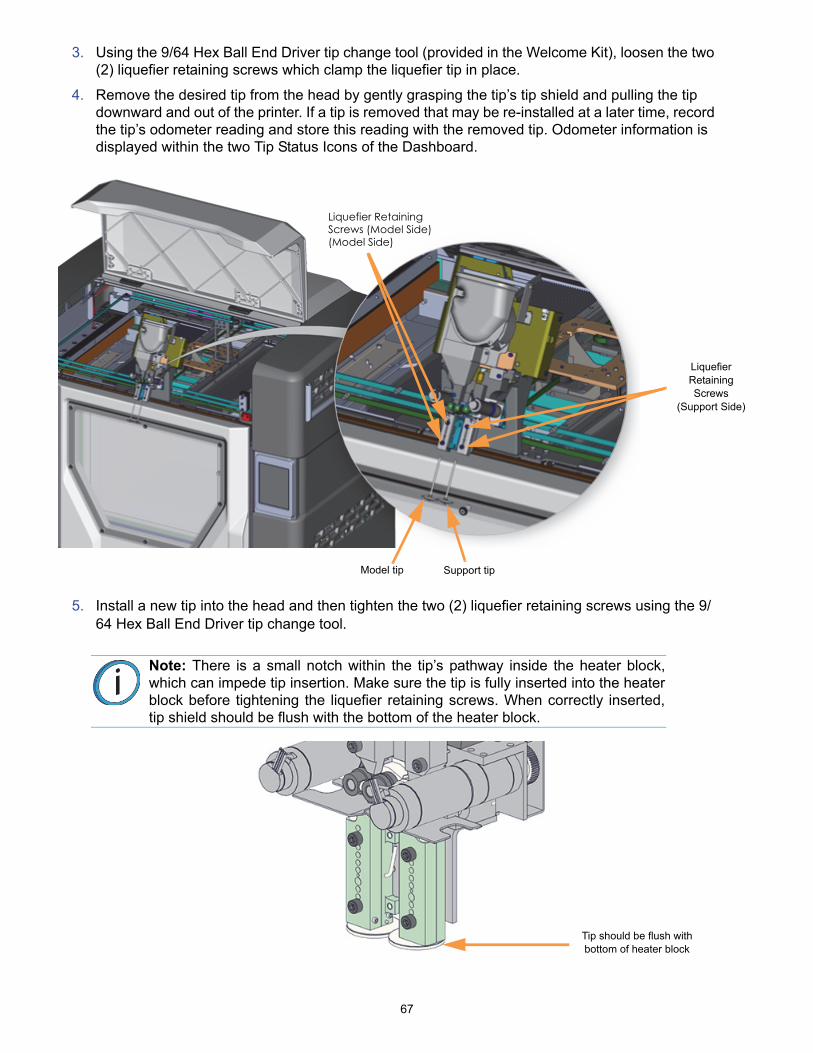
3. Using the 9/64 Hex Ball End Driver tip change tool (provided in the Welcome Kit), loosen the two (2) liquefier retaining screws which clamp the liquefier tip in place.
4. Remove the desired tip from the head by gently grasping the tip’s tip shield and pulling the tip downward and out of the printer. If a tip is removed that may be re-installed at a later time, record the tip’s odometer reading and store this reading with the removed tip. Odometer information is displayed within the two Tip Status Icons of the Dashboard.
5. Install a new tip into the head and then tighten the two (2) liquefier retaining screws using the 9/64 Hex Ball End Driver tip change tool.
Note: There is a small notch within the tip’s pathway inside the heater block,which can impede tip insertion. Make sure the tip is fully inserted into the heaterblock before tightening the liquefier retaining screws. When correctly inserted,tip shield should be flush with the bottom of the heater block.
Liquefier Retaining Screws
(Support Side)
Support tipModel tip
Liquefier RetainingScrews (Model Side)(Model Side)
Tip should be flush with bottom of heater block

68
6. Repeat steps 3 - 5 if an additional tip needs to be changed.
7. Remove the head from the head maintenance bracket and return head to its initial position. Secure the head to the head mounting plate using the two (2) recessed head mount fasteners.
8. Close the top cover.
9. After changing one or both tips, you must manually adjust tip wipe heights to ensure proper placement of the printer’s flicker/brush assemblies in relation to tips/tip shields. Adjust tip wipe heights as needed.
Note: Make sure the filament tubes, umbilical cable, and air hose are nottangled and are routed correctly.

69
BASIC JOB BUILD TASKS
BEFORE A BUILD
To build a job, you must first send the job file to the printer from the Control Center application installed on your workstation PC. Jobs are sent in CMB format and placed in the Job Queue (stored on the printer’s hard drive). The header of the CMB file contains the processed job’s basic information (material type, approximate material amount required for the build, tip size, etc.). This information is used to verify job compatibility with the printer’s existing configuration.
PREPARING THE PRINTER
To prepare the printer for a build:
1. Install a new build sheet.
A. Remove the plastic wrap from both sides of the build sheet.
B. Open the oven door and place the build sheet onto the platen.
• Make sure the build sheet is as centered as possible when placed onto the platen.• If the oven is hot, the build sheet will curl when placed on the platen. As the build sheet warms
up, it will flatten and adhere to the platen. Some adjustment of the build sheet may be necessary to seal it against the platen.
• Within about 5 minutes the printer should attain sufficient vacuum to secure the build sheet to the platen. The red X over the top of the Vacuum Status Indicator will disappear once sufficient vacuum is achieved. The Build State button will remain yellow at this point.
2. Make sure that the tip wipe assembly’s brushes as well as the printer’s tips are clean and that the purge bin is empty.
Warning: Wear proper safety equipment when handling items inside the oven.Surfaces in the build chamber can be very hot.
Note: Always use a new build sheet when building a job; the build sheet isintended for one-time use. Do not turn a build sheet over and place it on theplaten. Material residue on the sheet can adhere to the platen or interfere withthe build sheet vacuum.
Note: Using build sheets not provided by Stratasys may impact part quality andprinter reliability.
Note: ABS, ASA and PC parts use a clear build sheet. ULTEM parts use an amber-colored build sheet. Nylon 12 parts use a green tinted build sheet.

70
SELECTING A JOB TO BUILD
1. Select the Queue button within the Navigation Bar. The Queue page will open, and the Job Queue tab will be selected by default.
2. Within the Job Queue, select the job you wish to build by touching its entry in the list; the job’s row will turn blue. After selecting a job the Build State button will turn green.
• If you wish to select a job from the Sample Queue, toggle to the Sample Queue by touching its header within the Queue page and then selecting the job you wish to build by touching its entry in the list.
3. Return to the Build page by selecting the Build button from the Navigation Bar. The details of the job you selected will be displayed within the Print Job Selection Panel.
4. Compare the materials/tips requirements of the selected job to the printer’s current configuration. Ensure that loaded materials match the material requirements of the selected job, and installed tips match the tips required by the selected job.
• If the model and/or support materials loaded in the printer do not match the materials required to complete the build you will receive a warning.
5. Ensure that the active model and support canister bays have filament loaded to the head.
6. Press the Build (play) button within the Build page to start the build.
• If the Enable Part Placement setting is set to Off (default setting), a dialog will not be displayed and the job will automatically be built in the center of the build sheet.
• If you set the Enable Part Placement setting to On, a dialog will be displayed allowing you to select the job’s build location. The dialog contains a graphic representing your printer’s platen as well as a blue bounding box graphic (the imaginary box surrounding the part). Select the job’s build location by dragging and dropping the bounding box on the touchscreen. When finished, press the checkmark button to confirm your selected placement and start the build.
71
7. "Heating Oven and Tips" is displayed within the Information Bar. The oven will begin to heat to a set point temperature determined by the material types specified for the job. Please be patient.
8. After the oven and liquefier tips reach temperature "Finding Z Zero" is displayed within the Information Bar, and the printer performs a Z Zero Calibration.
9. Once Z Zero Calibration is complete the printer begins building the job. "Starting Part Build" is momentarily displayed within the Information Bar. "Building" is displayed within the Information Bar as the part is being built, and build progress is displayed within the Build page.
10. When finished, "Build Complete - Remove Part" is displayed within the Information Bar indicating that the completed part can be removed from the printer.
INFORMATION AVAILABLE DURING A BUILD
During a build, information pertaining to that build is displayed within two areas of the Build page:
The Print Job Information Panel displays the details of a job, as submitted to the printer from the workstation PC. This information is static and is for reference purposes only.
Information displayed within this panel for a selected job includes:
• Name of the job.• Model and support materials associated with the job.• Estimated build time for the job.• Name of the user that submitted the job.• Tip sizes associated with the job.• Number of layers in the job.
The Print Job Status section of the Build page is comprised of a two-part graphic which provides information on a building job.
• The Build Status portion of this graphic displays the build’s percentage of completion, number of completed layers as compared to total number of layers, elapsed build time as compared to total build time, expected build completion information, and build progress ring.
• The Materials Status portion of this graphic displays detailed material status information, for both model and support material, as it pertains to a selected job.
Build Status
Materials Status
72
BUILD WARNINGS
If the printer detects an issue that may affect a build, it will be indicated within the Dashboard. The Build State button will turn yellow or red depending on the severity of the warning. Pressing the Build State button will open a dialog indicating the reason(s) for the warning/error. The body of the dialog will contain information related to the cause of the warning/error. Depending on the type of warning, the canister load status text displayed beneath each Material Status Icon of the Tips page also provides information indicating the cause of a warning/error.
• When loading and unloading materials you may encounter load related warnings which need to be resolved prior to starting a build.
• When starting a build you may encounter a variety of warnings pertaining to the printer’s current materials and tips configuration. If the printer’s tips have not been calibrated, the materials/tips installed within the printer do not match the requirements of the build, or the printer does not contain enough material to complete the build, you will receive a warning instructing you to resolve this issue.
• In some cases, the warning will prevent you from starting a build and will need to be corrected before the printer can build a part.
• While the printer is building, various pause and abort related warnings may be displayed. Some of these warnings may be due to a manual pause or abort, while others may be the result of the printer automatically pausing or aborting a build. Depending on the severity of the warning you may or may not be able to resume building.
PAUSING A BUILD
During a build the Pause button within the Build page becomes selectable. The printer can pause automatically, or be manually paused using this button:
• An automatic pause occurs when a canister runs out of material, a failure is detected, etc.• A manual pause occurs whenever the Pause button is pressed.
When the printer is directed to pause:
1. The current toolpath is completed, the Z stage is lowered slightly, and then the head is parked. "Pausing" followed by "Build Paused" is displayed within the Information Bar.
• If an automatic pause occurs, pressing the Build State button will open a dialog indicating the reason for the pause condition (i.e. empty canister). Correct this condition and then press the checkmark button to exit the dialog.
2. To resume building, press the Build (play) button within the Build page. A resume command will be sent to the printer instructing it to resume the build.
3. "Resuming" will be displayed within the Information Bar and the Pause button will be shown in its selected state. Once the build resumes, "Building" will be displayed within the Information Bar and the Pause button will revert to it unselected state.
Note: You can choose to ignore the warning and continue the build, but partbuild quality will be unpredictable. A warning generated from a mis-match ofmodel/support material or from low/no vacuum cannot be bypassed.
Note: The printer will not resume building instantaneously, please be patient.
If the oven door or top cover are open, or if vacuum is not present, the part willnot resume building immediately. Press the Build State button to check for anyerrors in order to troubleshoot this situation.
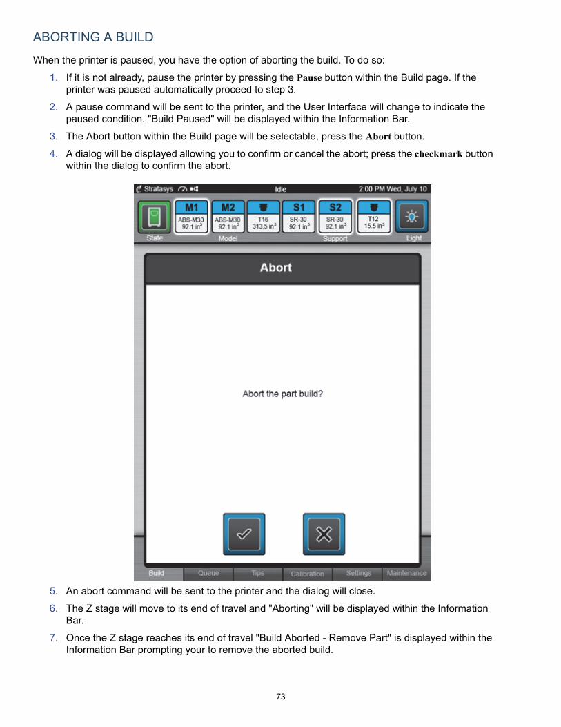
73
ABORTING A BUILD
When the printer is paused, you have the option of aborting the build. To do so:
1. If it is not already, pause the printer by pressing the Pause button within the Build page. If the printer was paused automatically proceed to step 3.
2. A pause command will be sent to the printer, and the User Interface will change to indicate the paused condition. "Build Paused" will be displayed within the Information Bar.
3. The Abort button within the Build page will be selectable, press the Abort button.
4. A dialog will be displayed allowing you to confirm or cancel the abort; press the checkmark button within the dialog to confirm the abort.
5. An abort command will be sent to the printer and the dialog will close.
6. The Z stage will move to its end of travel and "Aborting" will be displayed within the Information Bar.
7. Once the Z stage reaches its end of travel "Build Aborted - Remove Part" is displayed within the Information Bar prompting your to remove the aborted build.

74
AFTER A BUILD IS COMPLETE
After the completion of a build, the printer performs the following actions:
• The Z stage is lowered and the head is parked.• Depending on your printer’s auto cooldown configuration, the oven may or may not begin to
cool.• "Build Complete - Remove Part" is displayed within the Information Bar. • The Build Status Display graphic shows the build’s percentage of completion as 100% and the
outer progress ring is completely filled.• The Build State button turns yellow indicating a warning. Pressing this button will display a
dialog prompting you to remove the finished part.

75
REMOVING A PART FROM THE PRINTER
To remove a part from the printer:
1. Open the oven door.
2. Push up on the edge of the build sheet to release the vacuum grip. A red X will be displayed over the top of the Vacuum Status Indicator.
3. Remove the build sheet from the platen.
4. Remove debris that may have fallen onto the platen - use a vacuum or the Platen Dusting Brush (included in the Welcome Kit).
5. Carefully peel the part from the build sheet.
• If the part does not peel easily, use a metal scraper to carefully pry the part from the build sheet.
6. Remove supports from the completed part (material specific information and instructions can be found on the Stratasys Website and Customer Extranet).
• PC and PC-ISO material and ULTEM resin use break-away supports, called BASS. This support material must be removed manually; material should break away with relative ease. If necessary, use needle nose pliers or a pick (included in the Welcome Kit) to remove supports.
• Soluble Release support material is used with ABS-M30/ABS-M30i, ABS-ESD7, ASA, PC, PC-ABS, and Nylon 12 material. After building a part, you can remove supports using an Ultrasonic or Circulation Tank containing a solution of water and WaterWorks soluble solution. For more information on WaterWorks, refer to the WaterWorks User Guide located on Stratasys’ Customer Extranet.
Warning: Wear proper safety equipment when handling items inside the oven assurfaces within the oven can be very hot.
Note: If your printer’s Auto Cooldown setting is set to Always, allow the oven tocool to the standby temperature before removing the part.
Caution: Do not attempt to remove a part from the build sheet while the buildsheet is on the platen. Damage to the platen or platen level may occur.
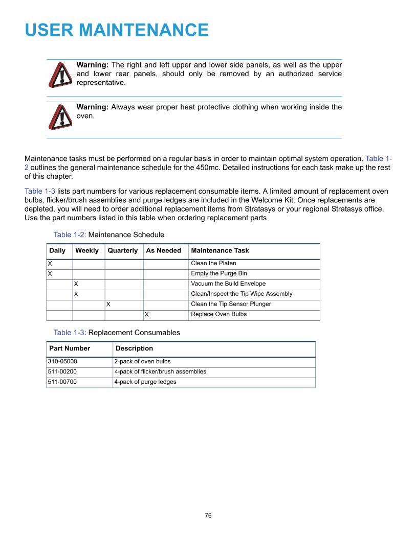
76
USER MAINTENANCE
Maintenance tasks must be performed on a regular basis in order to maintain optimal system operation. Table 1-2 outlines the general maintenance schedule for the 450mc. Detailed instructions for each task make up the rest of this chapter.
Table 1-3 lists part numbers for various replacement consumable items. A limited amount of replacement oven bulbs, flicker/brush assemblies and purge ledges are included in the Welcome Kit. Once replacements are depleted, you will need to order additional replacement items from Stratasys or your regional Stratasys office. Use the part numbers listed in this table when ordering replacement parts
Table 1-2: Maintenance Schedule
Table 1-3: Replacement Consumables
Warning: The right and left upper and lower side panels, as well as the upperand lower rear panels, should only be removed by an authorized servicerepresentative.
Warning: Always wear proper heat protective clothing when working inside theoven.
Daily Weekly Quarterly As Needed Maintenance Task
X Clean the Platen
X Empty the Purge Bin
X Vacuum the Build Envelope
X Clean/Inspect the Tip Wipe Assembly
X Clean the Tip Sensor Plunger
X Replace Oven Bulbs
Part Number Description
310-05000 2-pack of oven bulbs
511-00200 4-pack of flicker/brush assemblies
511-00700 4-pack of purge ledges
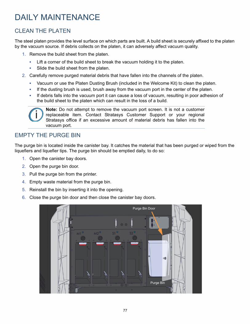
77
DAILY MAINTENANCE
CLEAN THE PLATEN
The steel platen provides the level surface on which parts are built. A build sheet is securely affixed to the platen by the vacuum source. If debris collects on the platen, it can adversely affect vacuum quality.
1. Remove the build sheet from the platen.
• Lift a corner of the build sheet to break the vacuum holding it to the platen. • Slide the build sheet from the platen.
2. Carefully remove purged material debris that have fallen into the channels of the platen.
• Vacuum or use the Platen Dusting Brush (included in the Welcome Kit) to clean the platen.• If the dusting brush is used, brush away from the vacuum port in the center of the platen.• If debris falls into the vacuum port it can cause a loss of vacuum, resulting in poor adhesion of
the build sheet to the platen which can result in the loss of a build.
EMPTY THE PURGE BIN
The purge bin is located inside the canister bay. It catches the material that has been purged or wiped from the liquefiers and liquefier tips. The purge bin should be emptied daily, to do so:
1. Open the canister bay doors.
2. Open the purge bin door.
3. Pull the purge bin from the printer.
4. Empty waste material from the purge bin.
5. Reinstall the bin by inserting it into the opening.
6. Close the purge bin door and then close the canister bay doors.
Note: Do not attempt to remove the vacuum port screen. It is not a customerreplaceable item. Contact Stratasys Customer Support or your regionalStratasys office if an excessive amount of material debris has fallen into thevacuum port.
Purge Bin
Purge Bin Door
78
WEEKLY MAINTENANCE
VACUUM THE BUILD ENVELOPE
The purge chute is designed to catch purged material debris and pass debris into the purge bin for disposal. However, some excess material debris may fall into the bottom of the build envelope. Do not allow excess material debris to accumulate in the build envelope as this could cause damage to the printer. Vacuum the build envelope on a weekly basis to remove build material debris and dust.
CLEAN/INSPECT TIP WIPE ASSEMBLY
You should clean the tip wipe assembly once a week. While cleaning the assembly, inspect the flicker/brush assemblies and purge ledges for wear and replace parts as necessary when wear is detected.
The flicker/brush assembly is replaced as a single unit. Once material is purged from a tip, the flicker portion of the flicker/brush assembly passes across the tip’s opening, cutting purged material off in small segments. The brush portion of the flicker/brush assembly then passes across the tip’s opening cleaning the tip and its tip shield. As a result, the flicker will wear at the location where the tip contacts its surface and eventually develop a notch large enough for the tip to completely pass through the flicker; a notched flicker cannot properly cut purging material. Similarly, material can become embedded within the bristles of the brush resulting in clumping; clumped bristles cannot properly clean a tip or its tip shield. The flicker should be replaced once a significant notch develops, and the brush should be replaced whenever bristle clumping (which cannot be removed with a brush) is apparent.
A purge ledge is replaced as a single unit; you do not need to replace a model side purge ledge and support side purge ledge together. Segments of purged material that have been knocked away from a tip’s opening by the flicker drop onto the purge ledge. Purged material is then balled up by the purge ledge, and transported through the purge chute into the purge waste bin. As a result, material buildup will accumulate on the surface of the purge ledge. A purge ledge should be replaced whenever excessive buildup has accumulated on the ledge’s surface.
To clean the tip wipe assembly and inspect its components:
1. Ensure that the printer is stopped (idle) and is not building.
2. Open the oven door.
3. Remove the two thumbscrews securing the purge chute access plate.
4. Carefully remove the purge chute access plate by pulling it up and out of its slot within the oven frame.
Hot Surface: Depending on how long the oven has been allowed to cool,components may be hot. If the printer’s thumbscrews are hot, wear the safetygloves provided in the Welcome Kit to perform all remaining steps.
Note: The glass pane within the purge chute access plate is loose and maypotentially break. Use caution when removing the purge chute access plate toensure that the glass pane does not fall from its slot.

79
5. Remove the model side purge ledge by lifting it upward until it clears it locating pin.
6. Repeat step 5 to remove and the support side purge ledge.

80
7. Remove the model side flicker/brush assembly by lifting it upward until it clears it locating pins.
8. Repeat step 7 to remove the support side flicker/brush assembly.
9. Clean and inspect the surface around the locating pins. Make sure that the purge ledges and flicker/brush assemblies can sit flush on the surface.
10. Inspect the purge ledges. Purge surfaces should be free from irregularities and excessive material buildup.
• Clean the purge ledges if they are to be reinstalled. • Replace the purge ledge(s) if excessive buildup has accumulated on the ledge’s surface.
Replacement purge ledges are supplied within the Welcome Kit. Once these replacements are depleted you will need to order additional replacement purge ledges.
Note: If the head is positioned above the purge area it may impede your abilityto remove the flicker/brush assemblies. Open the top cover and manually movethe head backwards and away from the purge area.
Note: For users who have purchased the High Performance material option,ULTEM 1010 requires a specific purge ledge. Always use the designatedULTEM 1010 purge ledge (indicated with the text "ULTEM 1010" on the face ofthe purge ledge) when building with this material.
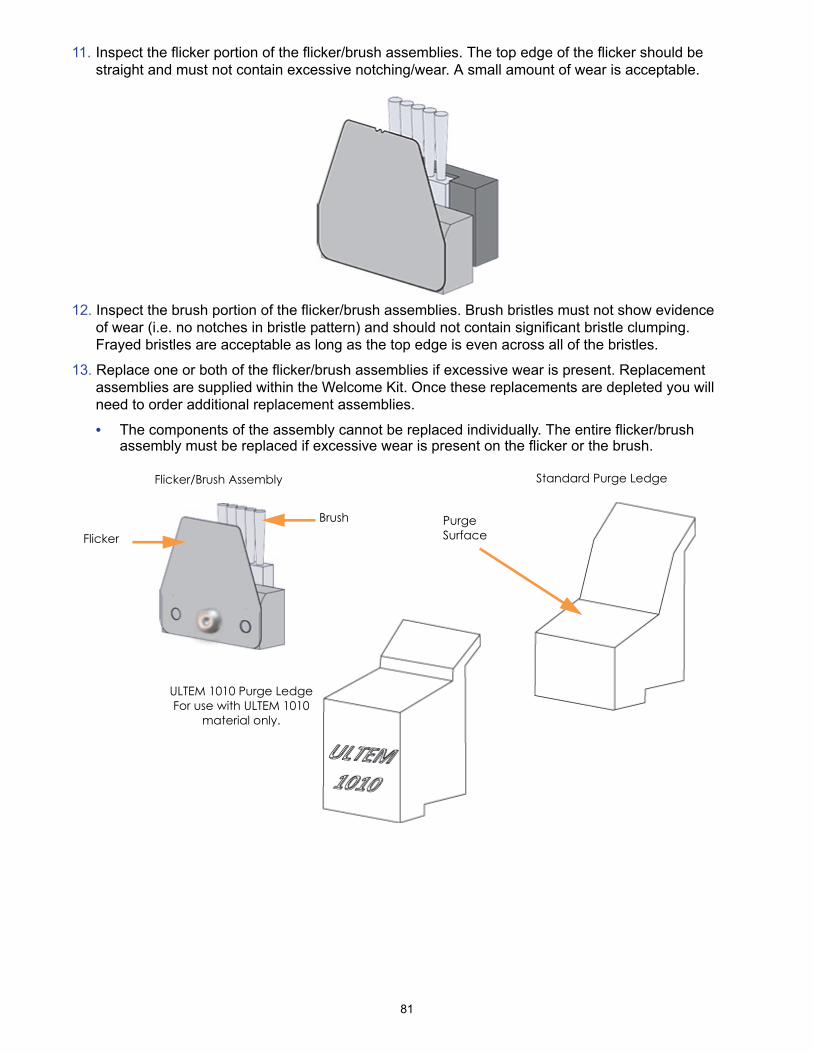
81
11. Inspect the flicker portion of the flicker/brush assemblies. The top edge of the flicker should be straight and must not contain excessive notching/wear. A small amount of wear is acceptable.
12. Inspect the brush portion of the flicker/brush assemblies. Brush bristles must not show evidence of wear (i.e. no notches in bristle pattern) and should not contain significant bristle clumping. Frayed bristles are acceptable as long as the top edge is even across all of the bristles.
13. Replace one or both of the flicker/brush assemblies if excessive wear is present. Replacement assemblies are supplied within the Welcome Kit. Once these replacements are depleted you will need to order additional replacement assemblies.
• The components of the assembly cannot be replaced individually. The entire flicker/brush assembly must be replaced if excessive wear is present on the flicker or the brush.
Flicker/Brush Assembly
Flicker
Brush
Standard Purge Ledge
Purge Surface
ULTEM 1010 Purge LedgeFor use with ULTEM 1010
material only.
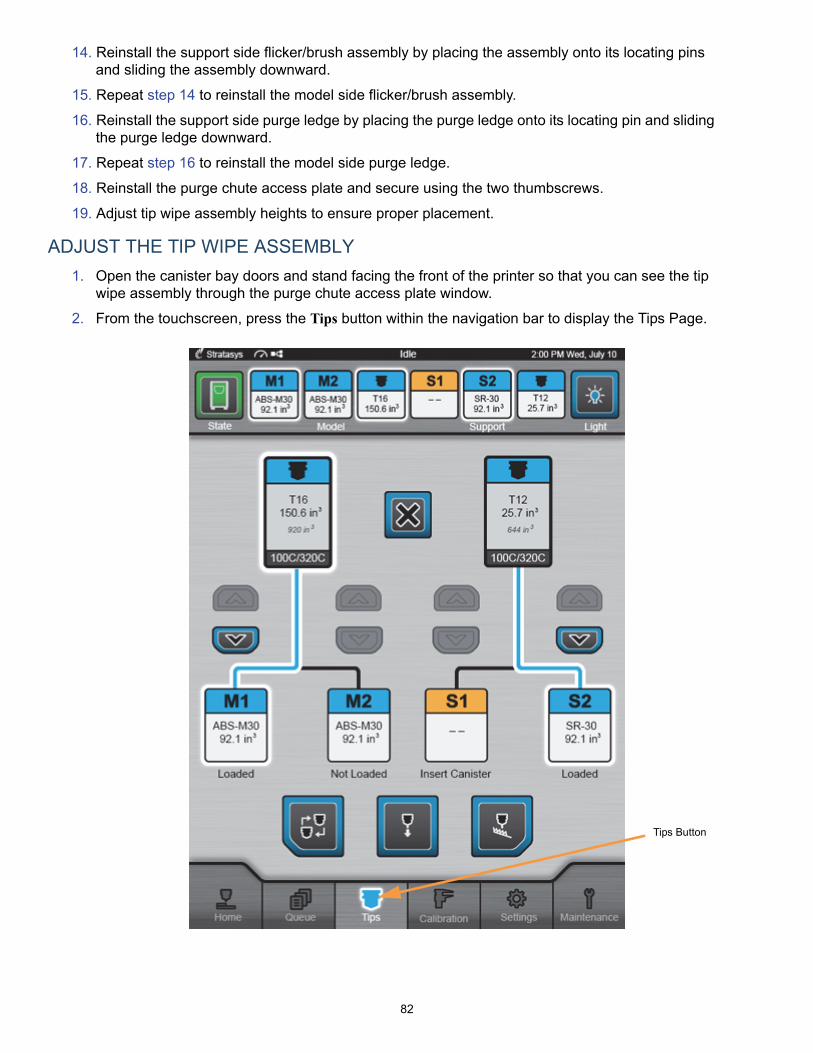
82
14. Reinstall the support side flicker/brush assembly by placing the assembly onto its locating pins and sliding the assembly downward.
15. Repeat step 14 to reinstall the model side flicker/brush assembly.
16. Reinstall the support side purge ledge by placing the purge ledge onto its locating pin and sliding the purge ledge downward.
17. Repeat step 16 to reinstall the model side purge ledge.
18. Reinstall the purge chute access plate and secure using the two thumbscrews.
19. Adjust tip wipe assembly heights to ensure proper placement.
ADJUST THE TIP WIPE ASSEMBLY
1. Open the canister bay doors and stand facing the front of the printer so that you can see the tip wipe assembly through the purge chute access plate window.
2. From the touchscreen, press the Tips button within the navigation bar to display the Tips Page.
Tips Button

83
3. Three buttons are displayed at the bottom of the Tips page (just above the Navigation Bar). These buttons are used to initiate a variety of tip related functions. Press the Tip Wipe Adjustment button.
4. Press the Go to Purge Position button; the head will move to the purge position.
5. Press the Wipe Tips button. After a few seconds the head will begin to move back and forth, slowly passing the model and support tips over the flicker/brush assemblies.
• The head will make 4 passes. With each pass, the head gradually moves horizontally across the flicker to ensure proper adjustment and even wear.
6. Observe placement via the purge chute access plate window and using the Tip Wipe Height Adjustment Wheels, adjust tip wipe height for the replaced tip(s).
• Top wheel corresponds to model tip, bottom wheel corresponds to support tip.
Tip Wipe Adjustment Button
Go to Purge Position Button
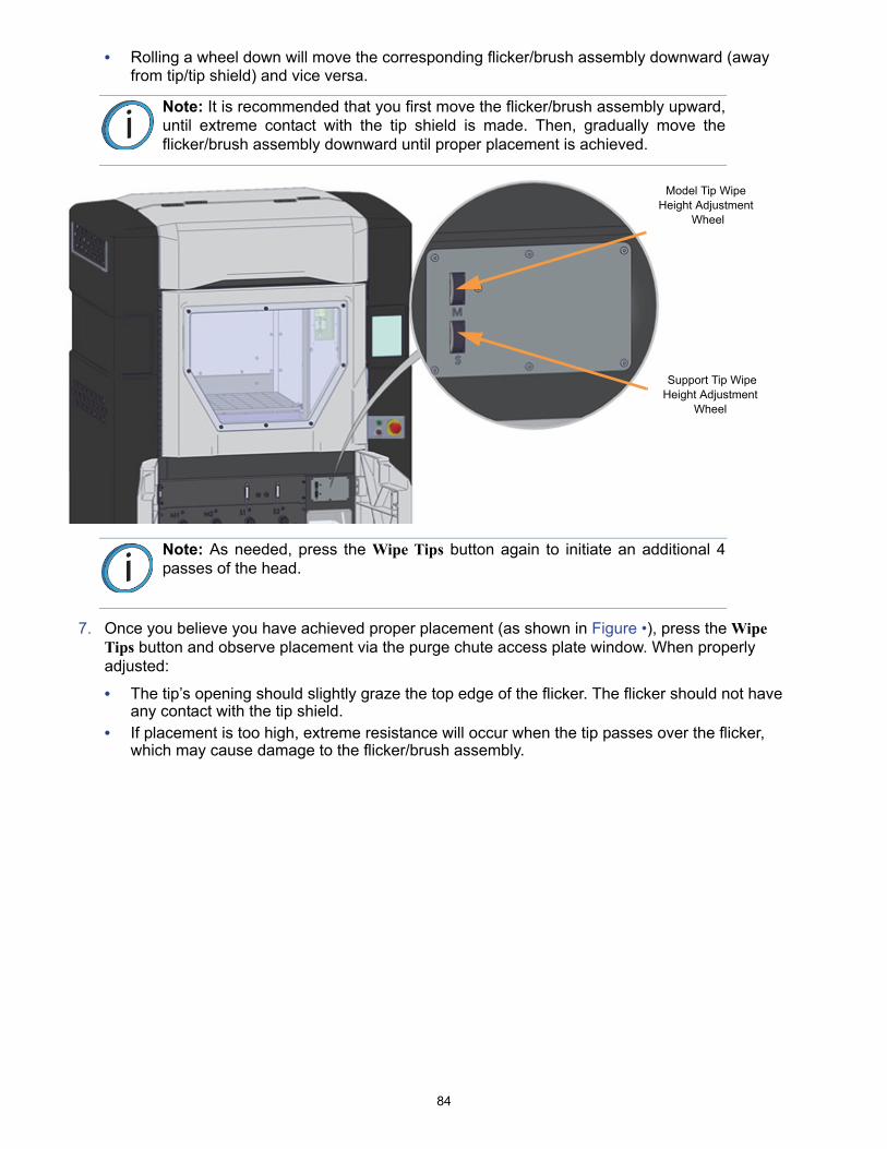
84
• Rolling a wheel down will move the corresponding flicker/brush assembly downward (away from tip/tip shield) and vice versa.
7. Once you believe you have achieved proper placement (as shown in Figure •), press the Wipe Tips button and observe placement via the purge chute access plate window. When properly adjusted:
• The tip’s opening should slightly graze the top edge of the flicker. The flicker should not have any contact with the tip shield.
• If placement is too high, extreme resistance will occur when the tip passes over the flicker, which may cause damage to the flicker/brush assembly.
Note: It is recommended that you first move the flicker/brush assembly upward,until extreme contact with the tip shield is made. Then, gradually move theflicker/brush assembly downward until proper placement is achieved.
Note: As needed, press the Wipe Tips button again to initiate an additional 4passes of the head.
Model Tip Wipe Height Adjustment
Wheel
Support Tip Wipe Height Adjustment
Wheel

85
8. If additional adjustments are needed readjust height using the Tip Wipe Height Adjustment Wheels. When finished, close the canister bay doors.
• If working within the Tip Change Wizard, press the X (Cancel) button when finished to exit the wizard.

86
QUARTERLY MAINTENANCE
CLEAN THE TIP SENSOR PLUNGER
Material debris can occasionally accumulate on the top of the tip sensor plunger. Excessive buildup can affect part build quality. To clean the tip sensor plunger:
1. Remove the plunger by gently pulling it up and out.
2. Remove material residue on the top of the plunger.
3. Replace the plunger in the sensor bracket - make sure the larger flat surface faces upward.
Hot Surface: Components can be hot; never touch the tip sensor plunger with your barehands.
It is recommended that you remove/replace the tip sensor plunger when the printer is poweredOFF or has been allowed to cool thoroughly.

87
AS NEEDED MAINTENANCE
REPLACE AN OVEN BULB
There are four festoon bulbs mounted on the front upper edge of the oven, two per side, which illuminate the oven. Bulbs will periodically burn out and require replacement. Bulbs generally will burn out in pairs. Use the following steps to replace an oven bulb:
1. With the oven light turned ON, take note of which bulb needs to be replaced.
2. Open the oven door. Ensure that you are wearing safety gloves and remove the burnt out bulb by gently pulling it out of the clamps securing it to the edge of the oven.
3. Install a replacement bulb by gently pressing it into place within the securing clamps.
Hot Surface: Bulbs are hot; never touch bulbs with your bare hands. Alwayswear safety gloves (provided in the Welcome Kit) when changing bulbs.
It is recommended that bulbs be removed/replaced when the printer is poweredOFF.
Note: Replacement bulb kits are supplied in the Welcome Kit. Once thesereplacements are depleted you will need to order additional replacement bulbkits.
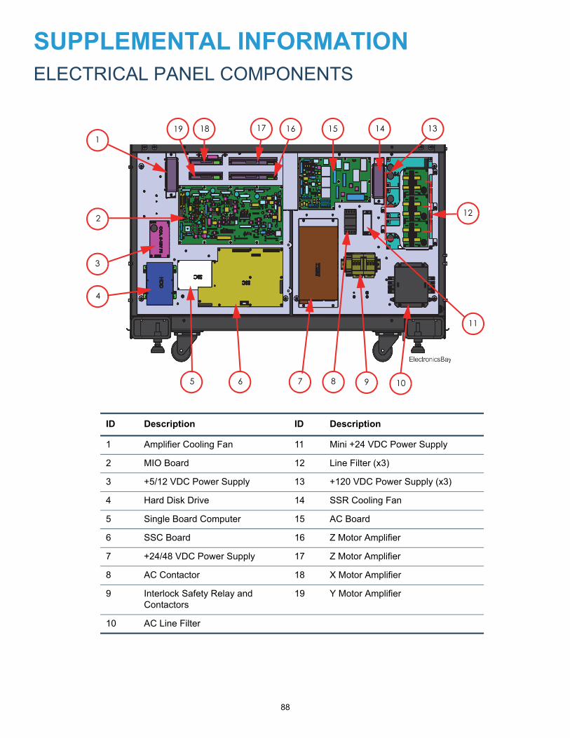
88
SUPPLEMENTAL INFORMATIONELECTRICAL PANEL COMPONENTS
ID Description ID Description
1 Amplifier Cooling Fan 11 Mini +24 VDC Power Supply
2 MIO Board 12 Line Filter (x3)
3 +5/12 VDC Power Supply 13 +120 VDC Power Supply (x3)
4 Hard Disk Drive 14 SSR Cooling Fan
5 Single Board Computer 15 AC Board
6 SSC Board 16 Z Motor Amplifier
7 +24/48 VDC Power Supply 17 Z Motor Amplifier
8 AC Contactor 18 X Motor Amplifier
9 Interlock Safety Relay and Contactors
19 Y Motor Amplifier
10 AC Line Filter
4
3
2
1
765 8
11
10
12
1314151619 18 17
9
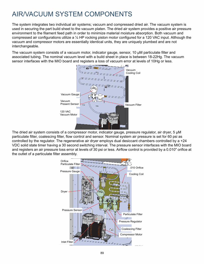
89
AIR/VACUUM SYSTEM COMPONENTS
The system integrates two individual air systems; vacuum and compressed dried air. The vacuum system is used in securing the part build sheet to the vacuum platen. The dried air system provides a positive air pressure environment to the filament feed path in order to minimize material moisture absorption. Both vacuum and compressed air configurations utilize a ¼ HP rocking piston motor configured for a 120 VAC input. Although the vacuum and compressor motors are essentially identical units, they are uniquely plumbed and are not interchangeable.
The vacuum system consists of a vacuum motor, indicator gauge, sensor, 10 µM particulate filter and associated tubing. The nominal vacuum level with a build sheet in place is between 18-22Hg. The vacuum sensor interfaces with the MIO board and registers a loss of vacuum error at levels of 10Hg or less.
The dried air system consists of a compressor motor, indicator gauge, pressure regulator, air dryer, 5 µM particulate filter, coalescing filter, flow control and sensor. Nominal system air pressure is set for 60 psi as controlled by the regulator. The regenerative air dryer employs dual desiccant chambers controlled by a +24 VDC solid state timer having a 30 second switching interval. The pressure sensor interfaces with the MIO board and registers an air pressure loss error at levels of 30 psi or less. Airflow control is provided by a 0.010" orifice at the outlet of a particulate filter assembly.
VacuumCooling Coil
VacuumPresent Sensor
120 VACVacuum Motor
Vacuum Gauge
Vacuum Filter
Compressor Motor
Coalescing Filter
Pressure Regulator
Particulate Filter
Cooling Coil
.010 Orifice
Inlet Filter
Pressure Sensor
Pressure Gauge
Dryer
OrificeParticulate Filter
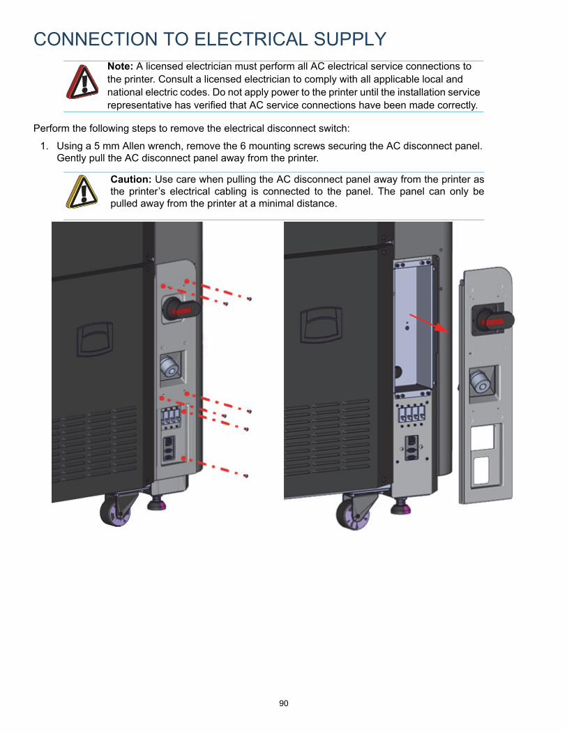
90
CONNECTION TO ELECTRICAL SUPPLY
Perform the following steps to remove the electrical disconnect switch:
1. Using a 5 mm Allen wrench, remove the 6 mounting screws securing the AC disconnect panel. Gently pull the AC disconnect panel away from the printer.
Note: A licensed electrician must perform all AC electrical service connections to the printer. Consult a licensed electrician to comply with all applicable local and national electric codes. Do not apply power to the printer until the installation service representative has verified that AC service connections have been made correctly.
Caution: Use care when pulling the AC disconnect panel away from the printer asthe printer’s electrical cabling is connected to the panel. The panel can only bepulled away from the printer at a minimal distance.
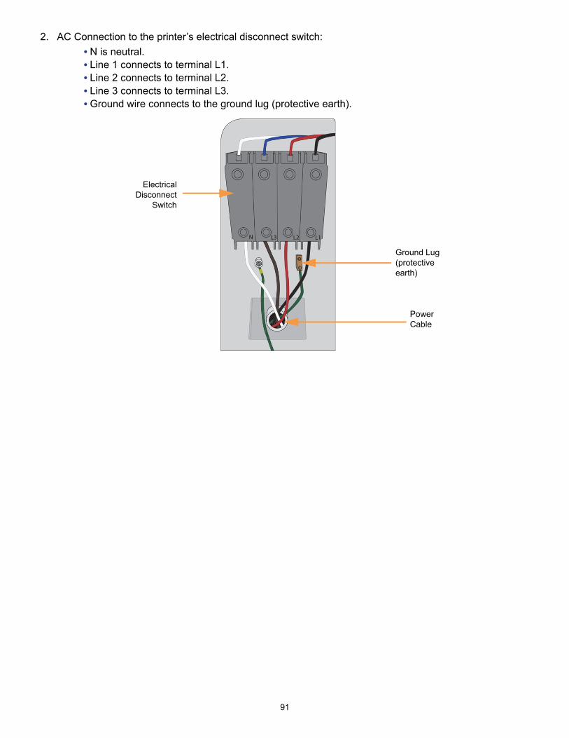
91
2. AC Connection to the printer’s electrical disconnect switch:
• N is neutral.• Line 1 connects to terminal L1.• Line 2 connects to terminal L2.• Line 3 connects to terminal L3.• Ground wire connects to the ground lug (protective earth).
ElectricalDisconnect
Switch
Ground Lug (protective earth)
Power Cable

92
ELECTRICAL DIAGRAMS
BLOCK DIAGRAM

93
POWER DISTRIBUTION DIAGRAMS
Figure 9: Ladder Diagram 1
Figure 10: Ladder Diagram 2

94
Figure 11: Ladder Diagram 3

95
SAFETY INTERLOCK DIAGRAM
• The oven door and top cover Interlock sensor switches utilize three contactor sets; one set is used to provide open/closed status to the MIO board CPLD. The other two sets of each sensor switch report this status to the safety control relay.
• The oven door sensor switch provides two cable connectors; P3 connector of cable 821698 interfaces switch status to the safety control relay.
• The top cover sensor switch provides two cable connectors; P4 connector of cable 821698 interfaces switch status to the safety control relay.
• Power (+24 VDC) to the safety control relay and dual contactors is provided by P5 of cable 821698.
• Power (+48 VDC) to the dual contactors is provided by P22 of cable 821698 on the MIO board.• One contact set of each of the dual contactors utilize +24 VDC to feedback contactor status to
the safety control relay.• No calibration or periodic testing of the interlock relays is required.

HEADQUARTERS7665 Commerce Way, Eden Prairie, MN 55344+1 888 480 3548 (US Toll Free)+1 952 937 3000 (Intl)+1 952 937 0070 (Fax)
2 Holtzman St., Science Park, PO Box 2496Rehovot 76124, Israel+972 74 745-4000+972 74 745 5000 (Fax)
ISO 9001:2008 Certified
For more information about Stratasys systems, materials, and applications contact your Stratasys representative or visit www.stratasys.com.
DOCUMENTATION FEEDBACK
Customers, resellers, and Stratasys employees are encouraged to send comments about our documentation and training to [email protected]. We greatly value your comments, review all of them, and use them to improve subsequent releases of the documentation. In your email message please include the document title, part number (located on the front cover), and page number. Please note that we do not respond to general questions or support requests submitted to this email address.