Embed Size (px)
Citation preview

EUROPEAN FINISHING EQUIPMENT Corp. 901 PENHORN AVE., UNIT #2 SECAUCUS, NJ 07094 PHONE (201) 210-2247 FAX (201) 210-2549 [email protected] www.histeam.com
Operating & Safety
Instructions
- - - - - - - - - - - - - - -
MVP-35 AUTO
Exclusive Distributor of ™ Brand Pressing Equipment

2
IMPORTANT SAFETY INSTRUCTIONS
MODEL MVP-35 AUTO
FOR COMMERCIAL USE ONLY
READ ALL INSTRUCTIONS BEFORE USING
SPECIAL SAFETY INSTRUCTIONS
1. NEVER UNSCREW THE WATER CAP (WITH SAFETY VALVE) DURING USE (WHILE THE BOILER
IS UNDER PRESSURE) as the pressurized steam can lead to scalds.
2. UNSCREW THE WATER CAP ONLY WHEN REPLACEMENT WATER CAP IS NEEDED.
3. Risk of fire -- turn off the boiler and iron switches and unplug the boiler when finished ironing.
4. To avoid a circuit overload, do not operate another high voltage appliance on the same circuit
GENERAL SAFETY INSTRUCTIONS
1. Use iron/boiler only for its intended use.
2. To protect against a risk of electric shock, do not immerse the iron/boiler in water or other liquids.
3. The iron/boiler should always be turned “Off” before unplugging iron or unplugging from outlet. Never
yank cord to disconnect from outlet; instead, grasp plug and pull to disconnect.
4. Do not allow cord to touch hot surfaces. Let boiler and iron cool completely before putting away.
5. Always disconnect appliance from electrical outlet when not in use. The iron must not be left unattended
while it is connected to the power supply. The plug must be removed from the receptacle (outlet) before the
water reservoir is filled with water.
6. Do not operate appliance with damaged cord or hose. Do not use if the appliance has been dropped, or has
visible signs of damage, or if the iron is leaking. To reduce the risk of electric shock, do not disassemble or
attempt to repair this unit. Take it to a qualified service person for examination and repair. Incorrect assem-
bly or repair could cause a risk of fire, electric shock, or injury to persons when the appliance is used.
7. Close supervision is necessary for any appliance being used by or near children. Do not leave appliance un-
attended while iron is on ironing board.
8. Burns could occur from touching hot metal parts, hot water or steam.
SAVE THESE INSTRUCTIONS

3
OPERATING INSTRUCTIONS
MODEL MVP-35 AUTO
A BOILER SET UP
1. Take boiler out of the box.
2. Place boiler on a flat floor.
3. Remove covering from pressure vessel opening (Diagram A, Item (02)) and discard. Screw on black water
cap. Do not overtighten.
4. Insert iron cord with black plug and black steam hose (Diagram C, Item 21) into the receptacle (Diagram A,
Item 06) and snap in until it clicks.
5. Insert metal cord supporter into the hole provided at the top of the boiler (Diagram A, Item 01) . Insert iron
cord and hose into loop on top of the cord supporter.
6. Install drain knob (Diagram B, Item 14) and secure with cotter pin (see Diagram D) provided.
B START UP
1. Insert threaded stem of wheel through hole in Stabilizing Leg (Diagram A, Item 9) and insert in hole on bot-
tom corner of boiler cabinet. Secure wheel and leg with “acorn nuts”. Repeat with remaining three wheels
and legs.
2. Extend Stabilizing Legs from bottom of cabinet. (Diagram A, Item 9)
3. Fill plastic water tank with clean tap water (DO NOT USE DISTILLED WATER).
4. Insert boiler water hose with wire leads (Diagram B, Item 12) completely into water tank. Do NOT insert
drain hose (Diagram B, Item 15) into the water tank.
5. Plug boiler into a properly grounded 120V 15 AMP OUTLET.
6. Turn on iron switch (Diagram A, Item 03) and boiler switch (Diagram A, Item 04). Both switches will light
up.
7. Set thermostat knob on the iron (Diagram C, Item 22) to desired temperature. These temperature settings are
approximate. Please note that the minimum setting for steam is “Cotton”. Always check temperature on hid-
den part of the garment.
8. When the pressure gauge (Diagram A, Item 08) reads approximately 40 PSI and the stream ready indicator
lamp lights up, you are ready to press. During ironing this light will go on and off and the pressure gauge
needle will move up and down. This is normal operating function.
C USING IRON/BOILER
1. To get steam, press the red thumb switch (Diagram C, Item 23) .
2. At the beginning of each pressing session, point the iron away from the garment, in a safe direction, and press
the red thumb switch on the iron to eliminate any condensate from the iron.

4
3. The volume of steam can be controlled by turning the black flow control knob (Diagram A, Item 07) on the
front of the boiler cabinet.
4. During operation, if water supply is used up, the boiler will “beep” to tell you to refill the water tank.
D SHUT DOWN
1. When finished pressing, turn off the boiler and iron switches and unplug the boiler.
2. Remove black water hose from water tank. Failure to remove black water hose will cause the boiler to over-
fill and require shut down and draining before the boiler can be used.
E CLEANING AND MAINTENANCE
Once a week (in hard water areas, every day), it is recommended to clean out the boiler unit using the follow-
ing procedure:
1. Turn off the iron switch and the boiler switch, unplug the boiler from the electrical outlet and
allow the boiler to cool and the pressure gauge to go down to “0”.
2. Remove water supply tank. Place a bucket or other suitable container (not included) under the
boiler drain hose (Diagram B, Item 15) located at the top of the water tank compartment. (Do
not use water supply tank for this purpose). When the boiler has completely cooled, slowly open
drain knob (Diagram B, Item 14) to drain the dirty water from the boiler.
WARNING: Do not open this drain knob when the boiler is under pressure. Opening this
drain knob under pressure can cause serious burns and injury.
3. When the boiler is empty, close the drain knob.

5
03
04
05
06
07
02
08
01
09
09
09
Diagram A

6
Legend
01
02
03
04
05
06
07
08
09
10
11
12
13
14
15
16
17
18
19
20
21
22
23
Cord holder support
Safety cap
Iron switch
Boiler switch
Steam ready lamp
Steam and power outlet
Steam flow knob
Pressure gauge
Stabilizing legs
N/A
Power cable
Boiler water hose
Water tank
Drain knob
Drain hose
N/A
N/A
N/A
N/A
N/A
Steam and power plug
Thermostat Knob
Red thumb switch
11 12
13
14
15
Diagram B
7
21
22
23
Diagram C
21 23
Diagram D
Drain Knob Installation
01
02
03
04
Cotter pin
Optional Steam gun
Professional Steam Iron
8
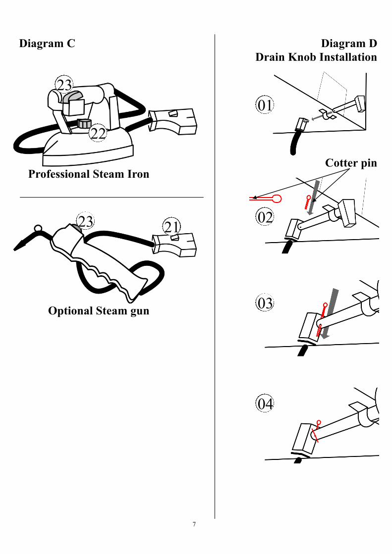
Diagram E
Boiler Parts List

9
MVP-AUTO Boiler Parts List (Diagram E)
Diagram # Description Part No.
1 Pressure Vessel MVPA013
2 Insulation Set-Vessel & Top MVPA014
3 Drain Tap and Nipple Set MVPA015
4 Knob for Draining tap MVPA016
5 Heating Element 120V MVP004A
5 Heating Element 220V MVP004AV
6 Thermostat with fuse for Boiler MVP003A
7 N/A
8 Water Cap (with Safety Valve) with 2 Extra Gaskets MVP030
9 Gasket for Water Cap (Pack of 5) MVP029S
10/11 Brass Ring with Silicone Packing MVP028
12 Gasket Packing MVP008
13 Complete Solenoid Valve 120V MVP035
13 Complete Solenoid Valve 220V MVP035V
14 Knob for Solenoid Valve MVP038
15 Hose Adaptor1/4 Male for Solenoid Valve MVPA017
16 Pressure Gauge MVP053
17 Pressure Switch MVP006
18 Male-Female Elbow MVPA018
19 Check Valve MVPA019
20 Boiler sensor MVPA020
21 Recharge Hose Set MVPA021
22 Electronic Board 120V MVPA022
22 Electronic Board 220V MVPA022V
23 Electronic Board Housing MVPA023
24 Taper straight adaptor male 3/8 MVPA024
25 Teflon hose d.8mm MVPA025
26 Elbow Adaptor 1/8 MVPA026
27 Pump Valve MVPA027
28 Water Pump 120V MVPA028
28 Water Pump 220V MVPA028V
29 Pump bracket MVPA029
30 Complete Steam/Power Outlet 120V MVPA030
30 Complete Steam/Power Outlet 220V MVPA030V
10
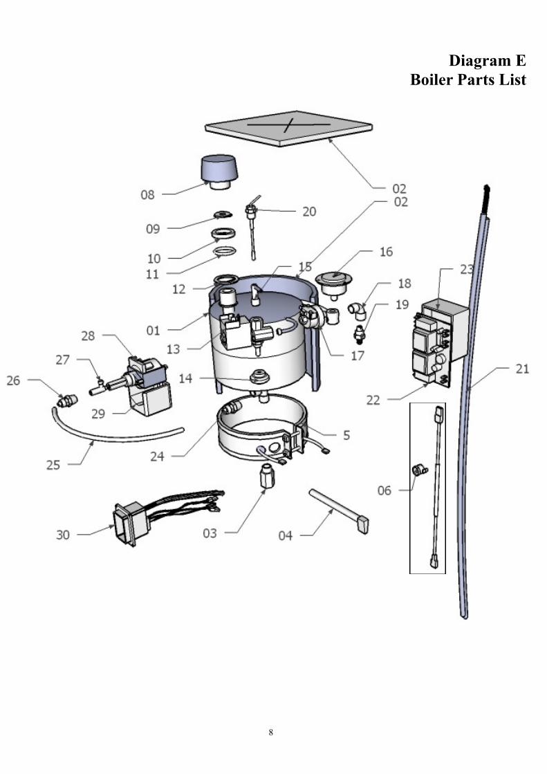
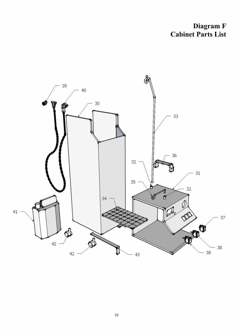
Diagram F
Cabinet Parts List
11
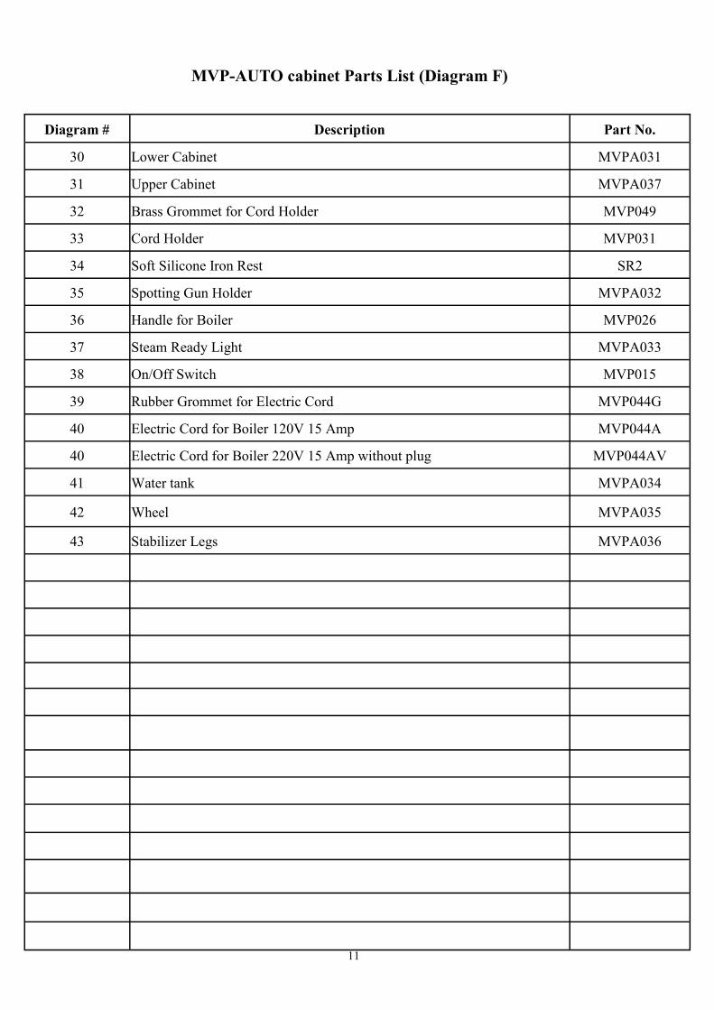
MVP-AUTO cabinet Parts List (Diagram F)
Diagram # Description Part No.
30 Lower Cabinet MVPA031
31 Upper Cabinet MVPA037
32 Brass Grommet for Cord Holder MVP049
33 Cord Holder MVP031
34 Soft Silicone Iron Rest SR2
35 Spotting Gun Holder MVPA032
36 Handle for Boiler MVP026
37 Steam Ready Light MVPA033
38 On/Off Switch MVP015
39 Rubber Grommet for Electric Cord MVP044G
40 Electric Cord for Boiler 120V 15 Amp MVP044A
40 Electric Cord for Boiler 220V 15 Amp without plug MVP044AV
41 Water tank MVPA034
42 Wheel MVPA035
43 Stabilizer Legs MVPA036

12
2
1
4
3
5
6
7
8 13
14
9
10
11
12
16
15
17
Diagram G
Iron Parts List

13
Iron Parts List (Diagram G)
Diagram # Description Part No.
1 Microswitch MVP021
2 Microswitch Cover MVP024
3 Iron Handle MVP042
4 Terminal Block MVP019
5 Back Terminal Cover MVP017
6 Thermostat with Thermal Fuse MVP013
7 Lead Wire-Thermostat to Terminal Block MVP051
8 Iron Heating Element w/Base 120V MVP010
9 Iron Cover MVP023
10 Hand Guard for Iron MVP037
11 Knob for Thermostat MVP022
12 Hose Nipple MVP009
13 Hose Clamp MVP014
14 Rubber Steam Hose MVP048
15 Iron Cord Supporter MVP027
16 Electric Cord for Iron MVP018
17 Steam/Power Plug MVPA012
14
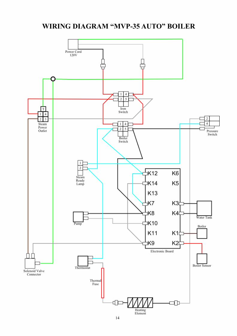
WIRING DIAGRAM “MVP-35 AUTO” BOILER

15
LIMITED WARRANTY for
MINI BOILERS with IRON
Hi-Steam Mini Boilers with Iron are warranted by European Finishing Equipment Corp. (“European Finishing”) to the original pur-
chaser against defects in workmanship and material, for a period of (a) 12 months for heating elements and pressure vessels, and (b) 90
days for all other parts, in either case from the date of original purchase, with the following limitations:
1 This warranty is contingent upon compliance with the installation, operation and maintenance instructions contained in the
equipment’s instruction manual. The equipment is intended solely for industrial use.
2 This warranty is limited to repair or replacement of defective parts plus the cost of labor, and does not cover any shipping cost
or other incidental costs.
3 This warranty is void for parts that are, in the sole judgment of European Finishing:
damaged from mishandling, faulty installation or adjustments, improper use or maintenance, corrosion, accident,
negligence, not operating within the specifications provided, failure to follow instructions, use of improper voltage,
etc.
damaged by causes beyond the control of European Finishing, such as fire, flood, earthquake, lightning, power
surge, damage in shipping, etc.
altered or repaired in any way that changes the original design, construction, specifications or performance, or by
replacing parts with unauthorized components.
expendable in the normal course of operation. Expendable items include, but are not limited to, the iron cords,
hoses, gaskets, etc
The warranty period on each repaired or replacement part in fulfillment of this warranty shall be for the unexpired portion of the original
warranty.
Defective equipment covered by this warranty must be shipped, freight prepaid, to one of European Finishing’s designated repair shops
for repair or for replacement of parts with new or refurbished parts. Repair or replacement of parts will be done at the discretion of the
designated repair shop .
Replacement or repair of parts is the sole and exclusive remedy available under this warranty. EXCEPT AS STATED IN THIS LIM-
ITED WARRANTY, THERE IS NO WARRANTY OF ANY KIND, EXPRESS OR IMPLIED, INCLUDING ANY WARRANTY OF
MERCHANTABILITY OR FITNESS FOR A PARTICULAR PURPOSE, OR ANY OTHER WARRANTIES OTHERWISE ARISING
BY OPERATION OF LAW, COURSE OF DEALING, CUSTOM, TRADE OR OTHERWISE.
In no event shall European Finishing be liable for any direct, indirect, consequential or incidental damages arising out of the use of or
inability to use the equipment or parts, even if it could foresee or has been advised of the possibility of such damage.
For warranty service by one of the designated repair shops in your area, please contact:
European Finishing Equipment Corp.
901 Penhorn Avenue, Unit #2
Secaucus, N.J. 07094
(888) 460-9292
10/10/11

16
EUROPEAN FINISHING EQUIPMENT Corp. 901 PENHORN AVE., UNIT #2
SECAUCUS, NJ 07094 PHONE (201) 210-2247 FAX (201) 210-2549
[email protected] www.histeam.com
January 2014