Embed Size (px)
Citation preview

Operating ManualSUNNY BOY 1.5 / 2.5
SB15-25-BE-en-10 | Version 1.0 ENGLISH

Legal ProvisionsThe information contained in these documents is property of SMA Solar Technology AG. Anypublication, whether in whole or in part, requires prior written approval by SMA Solar TechnologyAG. Internal reproduction used solely for the purpose of product evaluation or other proper use isallowed and does not require prior approval.
SMA WarrantyYou can download the current warranty conditions from the Internet at www.SMA-Solar.com.
TrademarksAll trademarks are recognized, even if not explicitly identified as such. A lack of identification doesnot mean that a product or symbol is not trademarked.The BLUETOOTH® word mark and logos are registered trademarks of Bluetooth SIG, Inc. and anyuse of these marks by SMA Solar Technology AG is under license.Modbus® is a registered trademark of Schneider Electric and is licensed by the ModbusOrganization, Inc.QR Code is a registered trademark of DENSO WAVE INCORPORATED.Phillips® and Pozidriv® are registered trademarks of Phillips Screw Company.Torx® is a registered trademark of Acument Global Technologies, Inc.
SMA Solar Technology AGSonnenallee 134266 NiestetalGermanyTel. +49 561 9522-0Fax +49 561 9522-100www.SMA.deE-mail: [email protected]© 2004 to 2015 SMA Solar Technology AG. All rights reserved.
Legal Provisions SMA Solar Technology AG
Operating ManualSB15-25-BE-en-102

Table of Contents1 Information on this Document ................................................. 51.1 Validity ................................................................................................ 51.2 Target Group...................................................................................... 51.3 Additional Information ....................................................................... 51.4 Symbols .............................................................................................. 61.5 Nomenclature..................................................................................... 61.6 Typographies...................................................................................... 6
2 Safety......................................................................................... 72.1 Intended Use ...................................................................................... 72.2 Safety Information.............................................................................. 7
3 Scope of Delivery...................................................................... 9
4 Product Description................................................................... 104.1 Sunny Boy........................................................................................... 104.2 Interfaces and Functions .................................................................... 134.3 LED Signals ......................................................................................... 15
5 Mounting ................................................................................... 165.1 Requirements for Mounting ............................................................... 165.2 Mounting the Inverter......................................................................... 18
6 Electrical Connection................................................................. 206.1 Safety during Electrical Connection.................................................. 206.2 Overview of the Connection Area .................................................... 216.3 AC Connection................................................................................... 21
6.3.1 Requirements for the AC Connection............................................ 216.3.2 Connecting the Inverter to the Utility Grid.................................... 236.3.3 Connecting Additional Grounding ............................................... 25
6.4 Connecting the Inverter to the Network ........................................... 266.5 DC Connection................................................................................... 28
6.5.1 Requirements for the DC Connection............................................ 286.5.2 Assembling the DC Connectors .................................................... 296.5.3 Connecting the PV Array ............................................................... 30
Table of ContentsSMA Solar Technology AG
Operating Manual 3SB15-25-BE-en-10

6.5.4 Disassembling the DC Connectors................................................ 31
7 Commissioning the Inverter ..................................................... 33
8 Using the Inverter User Interface ............................................ 348.1 Calling Up the Inverter User Interface .............................................. 34
8.1.1 Calling Up the Inverter User Interface via Direct Connection ..... 348.1.2 Calling Up the Inverter User Interface in the Local Network ...... 36
8.2 Design of the Inverter User Interface ................................................ 378.3 Changing the Password..................................................................... 398.4 Forgotten Password............................................................................ 40
9 Configuration ............................................................................ 419.1 Configuration Procedure.................................................................... 419.2 Starting the Installation Assistant ....................................................... 419.3 Starting the Self-Test (For Italy Only) ................................................ 429.4 Activating the Receipt of Control Signals (Only for Italy)................ 429.5 Deactivating Grounding Conductor Monitoring.............................. 439.6 Setting SMA OptiTrac Global Peak ................................................. 439.7 Saving the Configuration in a File..................................................... 449.8 Adopting a Configuration from a File............................................... 449.9 Updating the Firmware ...................................................................... 449.10 Integrating the Inverter into the Network.......................................... 459.11 Setting the Date and Device Time..................................................... 459.12 Configuring the Energy Meter........................................................... 459.13 Configuring Feed-In Management.................................................... 469.14 Changing Operating Parameters...................................................... 469.15 Configuring the Country Data Set..................................................... 479.16 Switching the Dynamic Power Display Off....................................... 489.17 Switching WLAN Off ......................................................................... 489.18 Switching WLAN On ......................................................................... 48
10 Disconnecting the Inverter from Voltage Sources.................. 50
11 Technical Data........................................................................... 52
12 Contact....................................................................................... 57
Table of Contents SMA Solar Technology AG
Operating ManualSB15-25-BE-en-104

1 Information on this Document
1.1 ValidityThis document is valid for the following device types from firmware version 2.0.1.R:• SB1.5-1VL-40 (Sunny Boy 1.5)• SB2.5-1VL-40 (Sunny Boy 2.5)
1.2 Target GroupThis document is intended for qualified persons and end users. Only qualified persons are allowedto perform the activities marked in this document with a warning symbol and the caption"Qualified person". Tasks that do not require any particular qualification are not marked and canalso be performed by end users. Qualified persons must have the following skills:• Knowledge of how an inverter works and is operated• Training in how to deal with the dangers and risks associated with installing and usingelectrical devices and installations
• Training in the installation and commissioning of electrical devices and installations• Knowledge of the applicable standards and directives• Knowledge of and compliance with this document and all safety information
1.3 Additional InformationLinks to additional information can be found at www.SMA-Solar.com:
Document title Document typeTroubleshooting, Cleaning and Decommissioning Service Manual
"Efficiency and Derating"Efficiency and Derating Behavior of the Sunny Boy, Sunny Tripowerand Sunny Mini Central Inverters
Technical Information
"Application for SMA Grid Guard Code" Certificate
"Circuit Breaker"Dimensioning and Selection of a Suitable AC Circuit Breaker for In-verters under PV-Specific Influences
Technical Information
"Criteria for Selecting a Residual-Current Device" Technical Information
"Temperature Derating"Causes of Temperature Derating and Possible Corrective Measures
Technical Information
"Overvoltage Protection"Measures For Lightning and Overvoltage Protection in PV Systems
Technical Information
"Webconnect Systems in Sunny Portal"Registration in Sunny Portal
User Manual
1 Information on this DocumentSMA Solar Technology AG
Operating Manual 5SB15-25-BE-en-10

1.4 SymbolsSymbol Explanation
Indicates a hazardous situation which, if notavoided, will result in death or serious injury
Indicates a hazardous situation which, if notavoided, can result in death or serious injury
Indicates a hazardous situation which, if notavoided, can result in minor or moderate injury
Indicates a situation which, if not avoided, can re-sult in property damage
Sections describing activities to be performed byqualified persons only
Information that is important for a specific topic orgoal, but is not safety-relevant
Indicates a requirement for meeting a specific goal
Desired result
A problem that might occur
1.5 NomenclatureComplete designation Designation in this documentSunny Boy Inverter, product
1.6 TypographiesTypography Use Examplebold • Display texts
• Elements on a user interface• Terminals• Elements to be selected• Elements to be entered
• The value can be found inthe field Energy.
• Select Settings.• Enter 10 in the field
Minutes.
> • Connects several elements to beselected
• Select Settings > Date.
[Button][Key]
• Button or key to be selected orpressed
• Select [Next].
1 Information on this Document SMA Solar Technology AG
Operating ManualSB15-25-BE-en-106
2 Safety
2.1 Intended UseThe Sunny Boy is a transformerless PV inverter which converts the direct current of the PV array togrid-compliant alternating current and feeds it into the utility grid.The product is suitable for indoor and outdoor use.The product must only be operated with PV arrays of protection class II in accordance withIEC 61730, application class A. The PV modules must be compatible with this product.PV modules with a high capacity to ground must only be used if their coupling capacity does notexceed 900 nF (for information on how to calculate the coupling capacity, see the TechnicalInformation "Leading Leakage Currents" at www.SMA-Solar.com).All components must remain within their permitted operating ranges at all times.The product must only be used in countries for which it is approved or released by SMA SolarTechnology AG and the grid operator.Use this product only in accordance with the information provided in the enclosed documentationand with the locally applicable standards and directives. Any other application may causepersonal injury or property damage.Alterations to the product, e.g. changes or modifications, are only permitted with the express writtenpermission of SMA Solar Technology AG. Unauthorized alterations will void guarantee andwarranty claims and usually void the operation permit. SMA Solar Technology AG shall not beheld liable for any damage caused by such changes.Any use of the product other than that described in the Intended Use section does not qualify asappropriate.The enclosed documentation is an integral part of this product. Keep the documentation in aconvenient place for future reference and observe all instructions contained therein.The type label must remain permanently attached to the product.
2.2 Safety InformationThis section contains safety information that must be observed at all times when working on or withthe product.To prevent personal injury and property damage and to ensure long-term operation of the product,read this section carefully and observe all safety information at all times.
2 SafetySMA Solar Technology AG
Operating Manual 7SB15-25-BE-en-10

Danger to life due to high voltages of the PV arrayWhen exposed to sunlight, the PV array generates dangerous DC voltage which is present in theDC conductors and the live components of the inverter. Touching the DC conductors or the livecomponents can lead to lethal electric shocks. If you disconnect the DC connectors from theinverter under load, an electric arc may occur leading to electric shock and burns.• Do not touch non-insulated cable ends.• Do not touch the DC conductors.• Do not touch any live components of the inverter.• Have the inverter mounted, installed and commissioned only by qualified persons with theappropriate skills.
• If an error occurs, have it rectified by qualified persons only.• Prior to performing any work on the inverter, disconnect it from all voltage sources asdescribed in this document (see Section 10 "Disconnecting the Inverter from VoltageSources", page 50).
Danger to life due to high voltages in the inverterTouching live components within the inverter can lead to lethal electric shocks. Some componentsalso require at least five minutes to discharge after the inverter has been disconnected fromvoltage sources.• Do not open the inverter.
Danger to life due to electric shockTouching an ungrounded PV module or array frame can cause a lethal electric shock.• Connect and ground the PV modules, array frame and electrically conductive surfaces sothat there is continuous conduction. Observe the applicable local regulations.
Damage to the inverter due to the use of cleaning agents• If the inverter is dirty, clean the enclosure, the enclosure lid, the type label and the LEDs usingonly clean water and a cloth.
2 Safety SMA Solar Technology AG
Operating ManualSB15-25-BE-en-108

3 Scope of DeliveryCheck the scope of delivery for completeness and any externally visible damage. Contact yourdistributor if the scope of delivery is incomplete or damaged.
Figure 1: Components included in the scope of delivery
Position Quantity DesignationA 1 Inverter
B 1 Negative DC connector
C 1 Positive DC connector
D 1 Clamping bracket
E 1 Cylindrical screw M5 x 16
F 1 Spring lock washer
G 1 Washer
H 1 AC connector
I 1 Connection cap
K 1 Quick reference guide with password label on the rearsideThe label contains the following information:• PIC (Product Identification Code) identification keyfor registering the PV system in Sunny Portal
• RID (Registration Identifier) registration ID forregistering the PV system in Sunny Portal
• WLAN password WPA2-PSK (Wi-Fi Protected Access2 - Preshared Key) for direct access to the inverter viaWLAN
3 Scope of DeliverySMA Solar Technology AG
Operating Manual 9SB15-25-BE-en-10

4 Product Description
4.1 Sunny BoyThe Sunny Boy is a transformerless PV inverter which converts the direct current of the PV array togrid-compliant alternating current and feeds it into the utility grid.
B
A
C
D
Figure 2: Design of the Sunny Boy
Position DesignationA DC Load-Break Switch
The inverter is equipped with a DC load-break switch. If the DC load-breakswitch is set to the position I, it establishes a conductive connection betweenthe PV array and the inverter. Setting the DC load-break switch to the O posi-tion interrupts the DC electric circuit and completely disconnects the PV arrayfrom the inverter. Disconnection takes place at all poles.
B LEDsThe LEDs indicate the operating state of the inverter.
4 Product Description SMA Solar Technology AG
Operating ManualSB15-25-BE-en-1010
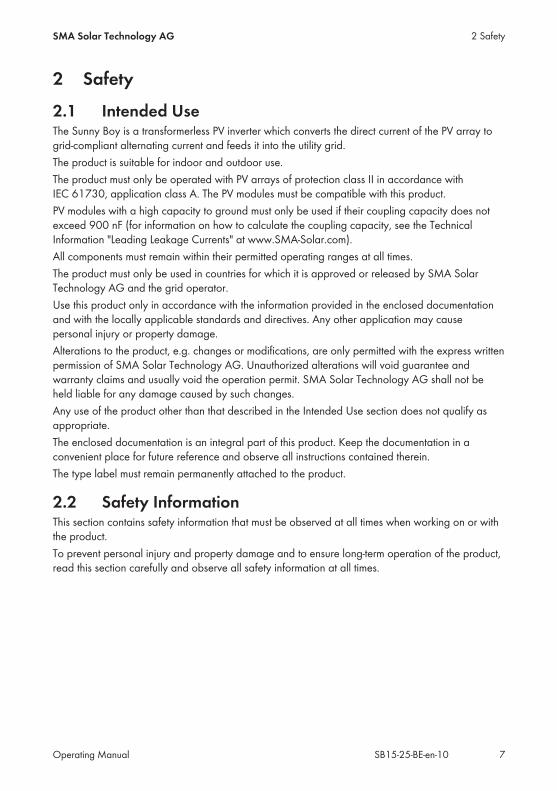
Position DesignationC Connection cap
Connection area with cable glands for connection to the utility grid and the lo-cal network
D Type labelThe type label uniquely identifies the inverter. You will require the informationon the type label to use the product safely and when seeking customer sup-port from the SMA Service Line. The type label must remain permanently at-tached to the product. You will find the following information on the type la-bel:• Device type (Model)• Serial number (Serial No.)• Date of manufacture• Identification key (PIC) for registration in Sunny Portal• registration ID (RID) for registration in Sunny Portal• WLAN password (WPA2-PSK) for direct access to the inverter via WLAN• Device-specific characteristics
Symbols on the Inverter and on the Type Label
Symbol ExplanationInverterTogether with the green LED, this symbol indicates the operatingstate of the inverter
Observe the documentationTogether with the red LED, this symbol indicates an error (for infor-mation regarding troubleshooting, see the service manual atwww.SMA-Solar.com)
Data transmissionTogether with the blue LED, this symbol indicates that the inverterhas an active network connection
Grounding conductorThis symbol indicates the position for connecting a grounding con-ductor.
Danger to life due to high voltages in the inverter; observe the wait-ing time of five minutesHigh voltages that can cause lethal electric shocks are present in thelive components of the inverter. Prior to performing any work on theinverter, disconnect it from all voltage sources as described in thisdocument (see Section 10, page 50).
4 Product DescriptionSMA Solar Technology AG
Operating Manual 11SB15-25-BE-en-10

Symbol ExplanationRisk of burns due to hot surfacesThe product can get hot during operation. Avoid contact during op-eration. Prior to performing any work on the product, allow the prod-uct to cool down sufficiently.
Danger to life due to electric shockThe product operates at high voltages. Prior to performing any workon the product, disconnect the product from voltage sources. Allwork on the product must be carried out by electrically qualified per-sons only.
Observe the documentationObserve all documentation supplied with the product.
DangerThis symbol indicates that the inverter must be additionally groundedif additional grounding or equipotential bonding is required at theinstallation site (see Section 6.3.3 "Connecting Additional Ground-ing", page 25).
Direct current
The product does not have a transformer.
Alternating current
WEEE designationDo not dispose of the product together with the household waste butin accordance with the disposal regulations for electronic waste ap-plicable at the installation site.
CE markingThe product complies with the requirements of the applicable EU di-rectives.
Degree of protection IP65The product is protected against dust intrusion and water jets fromany angle.
4 Product Description SMA Solar Technology AG
Operating ManualSB15-25-BE-en-1012

Symbol ExplanationThe product is suitable for outdoor installation.
RCM (Regulatory Compliance Mark)The product complies with the requirements of the applicable Aus-tralian standards.
4.2 Interfaces and FunctionsThe inverter is equipped with the following interfaces and functions:
Web server with user interface for configurationThe inverter is equipped as standard with an integrated web server that enables configuration ofthe inverter via an individual user interface. The inverter user interface can be called up directly viathe web browser in a computer, tablet PC or smartphone so long as there is a WLAN or Ethernetconnection (see Section 8 "Using the Inverter User Interface", page 34).
SMA SpeedwireThe inverter is equipped with SMA Speedwire as standard. SMA Speedwire is a type ofcommunication based on the Ethernet standard. This enables inverter-optimized 10/100 Mbit datatransmission between Speedwire devices in PV systems and the inverter user interface.
WebconnectThe inverter is equipped with a Webconnect function as standard. The Webconnect functionenables direct data transmission between the inverters of a small-scale system and the Internetportal Sunny Portal without any additional communication device and for a maximum of fourinverters per Sunny Portal system. In large-scale PV power plants, data transmission betweeninverters and the Internet portal Sunny Portal is carried out via the Sunny Home Manager. You canaccess your Sunny Portal system from any computer with an Internet connection.Webconnect enables - for PV systems operated in Italy - the connection or disconnection of theinverter to or from the utility grid and the specifying of the frequency limits to be used viaIEC61850-GOOSE messages.
WLANThe inverter is equipped with a WLAN interface as standard. The inverter is delivered with theWLAN interface activated as standard. If you do not want to use WLAN, you can deactivate theWLAN interface (see Section 9.17 "Switching WLAN Off", page 48). In addition, the inverter hasa WPS (WiFi Protected Setup) function. The WPS function connects the inverter automatically withan end device (e.g. smartphone, tablet PC or computer). You can activate the WPS function bytapping on the enclosure lid twice in quick succession. The open interface will then be signalizedvia the rapid flashing of the blue LED on the inverter.
4 Product DescriptionSMA Solar Technology AG
Operating Manual 13SB15-25-BE-en-10
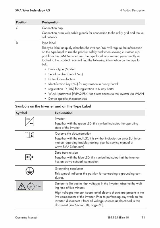
Limited function in the event of frostThe integrated WLAN interface is only designed for temperatures down to -20°C.• Deactivate the WLAN interface at low temperatures (see Section 9.17 "Switching WLANOff", page 48).
Grid Management ServicesThe inverter is equipped with service functions for grid management.Depending on the requirements of the grid operator, you can activate and configure the functions(e.g. active power limitation) via operating parameters.
SMA OptiTrac Global PeakSMA OptiTrac Global Peak is an advancement of SMA OptiTrac and allows the operating point ofthe inverter to follow the optimal operating point of the PV array (MPP) precisely at all times. Inaddition, with the aid of SMA OptiTrac Global Peak, the inverter detects several maximum powerpoints in the available operating range, such as may occur particularly with partially shadedstrings. SMA OptiTrac Global Peak is enabled by default.
All-pole sensitive residual-current monitoring unitThe all-pole sensitive residual-current monitoring unit detects alternating and direct differentialcurrents. In single-phase and three-phase inverters, the integrated differential current sensor detectsthe current difference between the neutral conductor and the line conductor(s). If the currentdifference increases suddenly, the inverter disconnects from the utility grid.
Connection of the SMA Energy MeterIf an SMA Energy Meter is installed in the PV system, the inverter can receive data on thehousehold energy consumption directly from this.
4 Product Description SMA Solar Technology AG
Operating ManualSB15-25-BE-en-1014

4.3 LED SignalsLED Status ExplanationGreen LED flashing Waiting for connection conditions
The LED is on for two seconds and then off for two sec-onds. The conditions for feed-in operation are not yet met.As soon as the conditions are met, the inverter will startfeed-in operation.
glowing Feed-in operation (Power: ≥ 90%, relative to the active power limit set)The inverter feeds in with a power of at least 90%.
pulsing Feed-in operation (Power: < 90%, relative to the active power limit set)The inverter feeds in with a power of less than 90%. TheLED flashes on and off uniformly. The higher the power,the greater the frequency. If required, you can switch thedynamic power display off (see Section 9.16 "Switchingthe Dynamic Power Display Off", page 48).
Red LED glowing ErrorIf an error occurs, a distinct error message and the corre-sponding event number will be displayed in addition onthe inverter user interface or in the communication prod-uct. The error must be rectified by a qualified person (fortroubleshooting, see the service manual at www.SMA-So-lar.com).
Blue LED flashes slowly forapprox. oneminute
Communication connection is being establishedThe inverter is establishing a connection to a local networkor creating an Ethernet direct connection to an end device(e.g. smartphone, tablet PC or computer).
flashes slowly forapprox. two min-utes
WPS activeThe WPS function of the inverter for WLAN direct connec-tion with an end device (e.g. smartphone, tablet PC orcomputer) is active.
glowing Communication activeThere is an active connection with a local network or anEthernet direct connection with an end device (e.g. smart-phone, tablet PC or computer).
4 Product DescriptionSMA Solar Technology AG
Operating Manual 15SB15-25-BE-en-10

5 Mounting
5.1 Requirements for MountingRequirements for the mounting location:
Danger to life due to fire or explosionDespite careful construction, electrical devices can cause fires.• Do not mount the inverter in areas containing highly flammable materials or gases.• Do not mount the inverter in a potentially explosive atmosphere.
Do not mount the inverter on a pillar. A solid support surface must be available for mounting, e.g. concrete or masonry. The support surface must be even. The difference between the outer anchoring points must notexceed 5 mm.
The mounting location must be suitable for the weight and dimensions of the inverter (seeSection 11 "Technical Data", page 52).
The mounting location should not be exposed to direct solar irradiation. Direct solar irradiationcan cause the inverter to overheat. As a result, the inverter reduces its power output.
The mounting location should be freely and safely accessible at all times without the need forany auxiliary equipment (such as scaffolding or lifting platforms). Non-fulfillment of thesecriteria may restrict servicing.
To ensure optimum operation, the ambient temperature should be between -25°C and 40°C. Climatic conditions must be met (see Section 11 "Technical Data", page 52).
5 Mounting SMA Solar Technology AG
Operating ManualSB15-25-BE-en-1016

Dimensions for mounting:
115 mm 105 mm240 mm
33
4 m
m2
3
mm
Figure 3: Position of the anchoring points
Recommended clearances:If you maintain the recommended clearances, adequate heat dissipation will be ensured. Thus, youwill prevent power reduction due to excessive temperature. Maintain the recommended clearances to walls as well as to other inverters or objects. If multiple inverters are mounted in areas with high ambient temperatures, increase theclearances between the inverters and ensure sufficient fresh-air supply.
5 MountingSMA Solar Technology AG
Operating Manual 17SB15-25-BE-en-10

Figure 4: Recommended clearances
Permitted and prohibited mounting positions: The inverter must only be mounted in one of the permitted positions. This will ensure that nomoisture can penetrate the inverter.
The inverter should be mounted in such a way that LED signals can be read without difficulty.15°
Figure 5: Permitted and prohibited mounting positions:
5.2 Mounting the Inverter
Additionally required mounting material (not included in the scope of delivery): Two stainless steel hexagon head wood screws (AF 10, diameter 6 mm), screw length must besuitable for the support surface and the weight of the inverter (fastening bracket thickness:4 mm)
If necessary, two screw anchors suitable for the support surface and the screws
5 Mounting SMA Solar Technology AG
Operating ManualSB15-25-BE-en-1018

Risk of injury when lifting the inverter, or if it is droppedThe inverter weighs 9 kg. There is risk of injury if the inverter is lifted incorrectly or dropped whilebeing transported or when attaching it to or removing it from the wall mounting bracket.• Transport and lift the inverter carefully.
Procedure:1.
Risk of injury due to damaged cablesThere may be power cables or other supply lines (e.g. gas or water) routed in the wall.• Ensure that no lines are laid in the wall which could be damaged when drilling holes.
2. Mark the position of the drill holes. Use the information on dimensioning given in thisdocument for this (see Section 5.1 "Requirements for Mounting", page 16).
3. Ensure that the positions marked are aligned horizontally.4. Drill the holes at the positions marked.5. If necessary, plug the screw anchors into the holes.6. Screw the screws in so that there is still at least 6 mm distance between the screw head andthe mounting surface.
7. Hang the inverter onto the screws using themetal brackets.
8. Tighten the screws hand-tight using a ratchet or box wrench. When doing this you cancompensate for any misalignment of the drill holes by aligning the metal brackets accordingly.
9. Ensure that the inverter is securely in place.
5 MountingSMA Solar Technology AG
Operating Manual 19SB15-25-BE-en-10
6 Electrical Connection
6.1 Safety during Electrical Connection
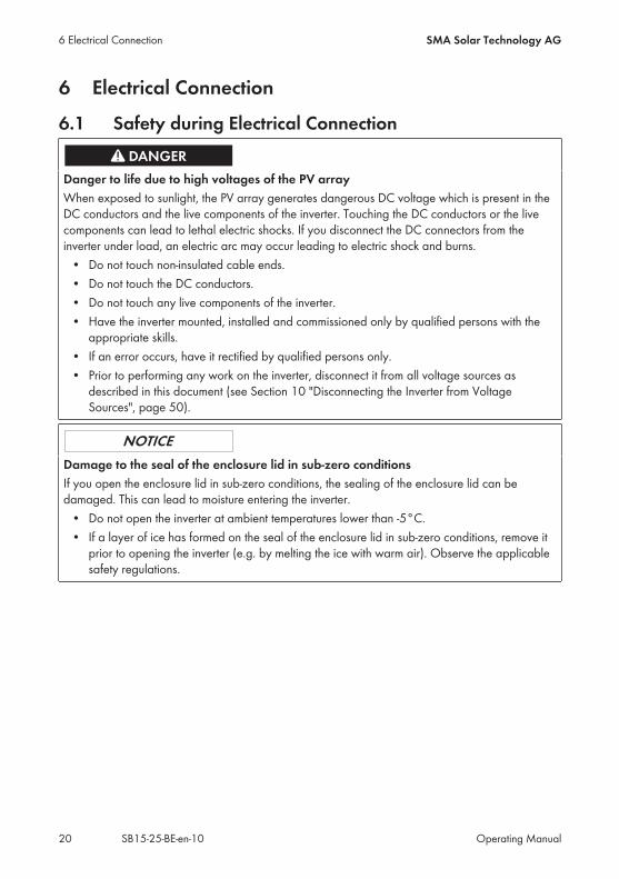
Danger to life due to high voltages of the PV arrayWhen exposed to sunlight, the PV array generates dangerous DC voltage which is present in theDC conductors and the live components of the inverter. Touching the DC conductors or the livecomponents can lead to lethal electric shocks. If you disconnect the DC connectors from theinverter under load, an electric arc may occur leading to electric shock and burns.• Do not touch non-insulated cable ends.• Do not touch the DC conductors.• Do not touch any live components of the inverter.• Have the inverter mounted, installed and commissioned only by qualified persons with theappropriate skills.
• If an error occurs, have it rectified by qualified persons only.• Prior to performing any work on the inverter, disconnect it from all voltage sources asdescribed in this document (see Section 10 "Disconnecting the Inverter from VoltageSources", page 50).
Damage to the seal of the enclosure lid in sub-zero conditionsIf you open the enclosure lid in sub-zero conditions, the sealing of the enclosure lid can bedamaged. This can lead to moisture entering the inverter.• Do not open the inverter at ambient temperatures lower than -5°C.• If a layer of ice has formed on the seal of the enclosure lid in sub-zero conditions, remove itprior to opening the inverter (e.g. by melting the ice with warm air). Observe the applicablesafety regulations.
6 Electrical Connection SMA Solar Technology AG
Operating ManualSB15-25-BE-en-1020

6.2 Overview of the Connection AreaC DA B
H G F
E
Figure 6: Connection areas and enclosure openings at the bottom of the inverter
Position DesignationA Positive DC connector
B Negative DC connector
C RJ45 pin connector for the network cable
D Pin connector for the AC connector
E Connection of the grounding terminal for additional grounding
F Cable gland for the AC cable
G Cable gland with filler plug for the network cable
H Connection cap
6.3 AC Connection
6.3.1 Requirements for the AC ConnectionCable requirements: External diameter: 5 mm to 13 mm Conductor cross-section: 1.5 mm² to 4 mm² Insulation stripping length: 15 mm
6 Electrical ConnectionSMA Solar Technology AG
Operating Manual 21SB15-25-BE-en-10

Sheath stripping length: 70 mm The cable must be dimensioned in accordance with the local and national directives for thedimensioning of cables. The requirements for the minimum wire size derive from thesedirectives. Examples of factors influencing cable dimensioning are: nominal AC current, type ofcable, routing method, cable bundling, ambient temperature and maximum desired line losses(for calculation of line losses, see the design software "Sunny Design" from softwareversion 2.0 at www.SMA-Solar.com).
Load-break switch and cable protection:
Damage to the inverter due to the use of screw-type fuses as load-break switchesScrew-type fuses (e.g. DIAZED fuse or NEOZED fuse) are not load-break switches.• Do not use screw-type fuses as load-break switches.• Use a load-break switch or circuit breaker as a load disconnection unit (for information anddesign examples, see the Technical Information "Circuit Breaker" at www.SMA-Solar.com).
In PV systems with multiple inverters, protect each inverter with a separate circuit breaker.Make sure to observe the maximum permissible fuse protection (see Section 11 "TechnicalData", page 52). This will prevent residual voltage being present at the corresponding cableafter disconnection.
Loads installed between the inverter and the circuit breaker must be fused separately.
Residual-current monitoring unit: If an external residual-current device is required, install a residual-current device which trips ata residual current of 100 mA or higher (for details on selecting a residual-current device, seethe Technical Information "Criteria for Selecting a Residual-Current Device" at www.SMA-Solar.com).
Overvoltage category:The inverter can be used in grids of overvoltage category III or lower in accordance withIEC 60664-1. That means that the inverter can be permanently connected to the grid-connectionpoint of a building. In case of installations with long outdoor cabling routes, additional measures toreduce overvoltage category IV to overvoltage category III are required (see the TechnicalInformation "Overvoltage Protection" at www.SMA-Solar.com).
Grounding conductor monitoring:The inverter is equipped with a grounding conductor monitoring device. This grounding conductormonitoring device detects when there is no grounding conductor connected and disconnects theinverter from the utility grid if this is the case. Depending on the installation site and gridconfiguration, it may be advisable to deactivate the grounding conductor monitoring. This isnecessary, for example, in an IT system if there is no neutral conductor present and you intend toinstall the inverter between two line conductors. If you are uncertain about this, contact your gridoperator or SMA Solar Technology AG. Grounding conductor monitoring must be deactivated after initial start-up depending on thegrid configuration (see Section 9.5, page 43).
6 Electrical Connection SMA Solar Technology AG
Operating ManualSB15-25-BE-en-1022

Safety in accordance with IEC 62109 when the grounding conductor monitoring isdeactivatedIn order to guarantee safety in accordance with IEC 62109 when the grounding conductormonitoring is deactivated, carry out one of the following measures:• Connect an additional grounding that has at least the same cross-section as theconnected grounding conductor to the connecting terminal plate for the AC cable (seeSection 6.3.3, page 25). This prevents touch current if the grounding conductor at theconnecting terminal plate for the AC cable fails.
Connection of additional groundingIn some countries, additional grounding is generally required. In each case, observe thelocally applicable regulations.• If additional grounding is required, connect an additional grounding that has at least thesame cross-section as the connected grounding conductor to the connecting terminalplate for the AC cable (see Section 6.3.3, page 25). This prevents touch current if thegrounding conductor at the connecting terminal plate for the AC cable fails.
6.3.2 Connecting the Inverter to the Utility Grid
Requirements: Only the AC connector supplied may be used. The connection requirements of the grid operator must be met. The grid voltage must be in the permissible range. The exact operating range of the inverter isspecified in the operating parameters.
Procedure:1. Disconnect the circuit breaker and secure it against reconnection.2. Unscrew the swivel nut from the cable gland forthe AC connection.
3. Thread the swivel nut over the AC cable.
4. Thread the AC cable through the cable gland.
6 Electrical ConnectionSMA Solar Technology AG
Operating Manual 23SB15-25-BE-en-10

• If the external diameter of the cable isbetween 5 mm and 7 mm, thread the cablethrough the cable gland directly.
• If the external diameter of the cable isbetween 8 mm and 13 mm, first remove theinner sealing ring from the cable gland andthen thread the cable through the cablegland. When doing so, ensure that theouter sealing ring is positioned correctly inthe cable gland.
3
4
2
1
5. Dismantle 70 mm of the AC cable.6. Shorten both L and N by 5 mm respectively, in order that the grounding conductor is the lastto become detached in the event of tension.
7. Strip 15 mm of the insulation of L, N and the grounding conductor.8. Connect L, N and the grounding conductor tothe connecting terminal plate of the supplied ACplug in accordance with the labeling. Whendoing so, ensure that the conductors areplugged completely into the terminal up to theinsulation. Tip: To detach the conductors, plug a flat-bladescrewdriver (blade width: 3 mm) into therectangular openings positioned behind them.
9. Make sure that all conductors are securely in place.
6 Electrical Connection SMA Solar Technology AG
Operating ManualSB15-25-BE-en-1024

10. Plug the AC connector into the pin connector inthe inverter until it snaps into place.
11. Check to ensure that the AC connector is securely in place by pulling lightly on the ACconnector.
12. Tighten the swivel nut slightly.13. If you would like to integrate the inverter into a local network via Ethernet, connect the inverternow (see Section 6.4, page 26).
14. Attach the connection cap to the inverter usingthe three screws and a Torx screwdriver (TX20)(torque: 3.5 Nm).
1
2
3
15. Tighten the swivel nut hand-tight.
6.3.3 Connecting Additional Grounding
If additional grounding or equipotential bonding is required locally, you can connect additionalgrounding to the inverter. This prevents touch current if the grounding conductor at the terminal forthe AC cable fails.The required clamping bracket, the cylindrical screw M5x16, the washer and the spring lockwasher are part of the scope of delivery of the inverter.
Cable requirements:
Use of fine-stranded conductorsYou can use an inflexible or a flexible, fine-stranded conductor.• When using a fine-stranded conductor, it has to be double crimped by a ring terminal lug.Make sure that no insulated conductor is visible when pulling or bending. This will ensuresufficient strain relief by means of the ring terminal lug.
Grounding cable cross-section: max. 10 mm²
6 Electrical ConnectionSMA Solar Technology AG
Operating Manual 25SB15-25-BE-en-10

Procedure:1. Strip off 12 mm of the grounding cable insulation.2. Thread the screw through the spring lock washer, the clamping bracket and the washer.3. Screw the screw into the thread slightly.4. Lead the grounding cable between the washerand clamping bracket and tighten the screw(torque: 6 Nm) using a Torx screwdriver (TX25).
6.4 Connecting the Inverter to the Network
Additionally required material (not included in the scope of delivery): One network cable Where required: Field-assembly RJ45 connector. SMA Solar Technology AG recommends theconnector "MFP8 T568 A Cat.6A" from "Telegärtner".
When laying the network cable outdoors: Overvoltage protection of the installation betweenthe network cable from the inverter and the local network in the building. The overvoltageprotection prevents overvoltages from being conducted via the network cable into the buildingand to other network devices in the event of a lightning strike.
Cable requirements:The cable length and quality affect the quality of the signal. Observe the following cablerequirements. Cable type: 100BaseTx Cable category: Cat5, Cat5e, Cat6, Cat6a or Cat7 Plug type: RJ45 of Cat5, Cat5e, Cat6 or Cat6a Shielding: SF/UTP, S/UTP, SF/FTP or S/FTP Number of insulated conductor pairs and insulated conductor cross-section: at least2 x 2 x 0.22 mm²
Maximum cable length between two nodes when using patch cables: 50 m Maximum cable length between two nodes with installation cable: 100 m UV-resistant for outdoor use
Procedure:1.
Danger to life due to electric shock• If the inverter is already in operation, disconnect the inverter from voltage sources (seeSection 10, page 50).
6 Electrical Connection SMA Solar Technology AG
Operating ManualSB15-25-BE-en-1026

2. When using a self-assembly network cable, assemble the RJ45 connector and connect to thenetwork cable (see connector documentation).
3. Remove the swivel nut from the cable gland for the network connection on the connection cap.4. Thread the swivel nut over the network cable.5. Remove the seal insert from the cable gland.6. Remove one filler plug from the seal insert.7. Push the network cable into the side slot in theseal insert.
8. Thread the network cable through the cable gland.9. Plug the network connector into the pinconnector in the inverter until it snaps into place.
10. Ensure that the network connector is securely in place by pulling slightly on the cable.11. Push the seal insert back into the cable gland.
12. Tighten the swivel nut slightly.
6 Electrical ConnectionSMA Solar Technology AG
Operating Manual 27SB15-25-BE-en-10

13. Attach the connection cap to the inverter usingthe three screws and a Torx screwdriver (TX20)(torque: 3.5 Nm).
1
2
3
14. Tighten the swivel nuts of the AC cable gland and network connection hand-tight.15. If the inverter is installed outdoors, install overvoltage protection.16. Connect the other end of the network cable directly to the computer or router or connect it toanother node. You can only connect the inverter to other nodes via star topology.
6.5 DC Connection
6.5.1 Requirements for the DC ConnectionRequirements for the PV modules of a string: All PV modules must be of the same type. All PV modules must be aligned identically. All PV modules must have the same tilt angle. The thresholds for the input voltage and the input current of the inverter must be adhered to(see Section 11 "Technical Data", page 52).
On the coldest day based on statistical records, the open-circuit voltage of the PV array mustnever exceed the maximum input voltage of the inverter.
Use of Y adapters for parallel connection of stringsThe Y adapters must not be used to interrupt the DC circuit.• Do not use the Y adapters in the immediate vicinity of the inverter. The adapters must notbe visible or freely accessible.
• In order to interrupt the DC circuit, always disconnect the inverter as described in thisdocument (see Section 10 "Disconnecting the Inverter from Voltage Sources", page 50).
6 Electrical Connection SMA Solar Technology AG
Operating ManualSB15-25-BE-en-1028

6.5.2 Assembling the DC Connectors
For connection to the inverter, all PV module connection cables must be fitted with the DCconnectors provided. Assemble the DC connectors as described in the following. Be sure to observethe correct polarity. The DC connectors are marked with the symbols "+" and "−".
Figure 7: Negative (A) and positive (B) DC connectors
Cable requirements: Cable type: PV1-F, UL-ZKLA, USE2 External diameter: 5 mm to 8 mm Conductor cross-section: 2.5 mm² to 6 mm² Qty single wires: minimum 7 Nominal voltage: minimum 1,000 V
Danger to life due to high voltages on DC conductorsWhen exposed to sunlight, the PV array generates dangerous DC voltage which is present in theDC conductors. Touching the DC conductors can lead to lethal electric shocks.• Cover the PV modules.• Do not touch the DC conductors.
Procedure:1. Strip 12 mm of the cable insulation.2. Insert the stripped cable into the DC connectorup to the stop. When doing so, ensure that thestripped cable and the DC connector are of thesame polarity.
+
3. Press the clamping bracket down until it audiblysnaps into place.
+
6 Electrical ConnectionSMA Solar Technology AG
Operating Manual 29SB15-25-BE-en-10

The stranded wire can be seen inside theclamping bracket chamber.
+
The stranded wire cannot be seen in the chamber?The cable is not correctly in place.• Release the clamping bracket. To doso, insert a screwdriver (blade width:3.5 mm) into the clamping bracketand pry the clamping bracket open.
+
1
2
• Remove the cable and go back to step 2.4. Push the swivel nut up to the thread and tighten(torque: 2 Nm).
+
1
2
6.5.3 Connecting the PV Array
Damage to the DC connectors due the use of contact cleaner of other cleaning agentsSome contact cleaners or other cleaning agents may contain substances that decompose theplastic of the DC connectors.• Do not use contact cleaners or other cleaning agents for cleaning the DC connectors.
1. Ensure that the circuit breaker is switched off and that it cannot be reconnected.2. If an external DC load-break switch is installed, disconnect the external DC load-break switchfrom all voltage sources.
6 Electrical Connection SMA Solar Technology AG
Operating ManualSB15-25-BE-en-1030

3. Set the DC load-break switch of the inverter toposition O.
4. Measure the PV array voltage. Ensure that the maximum input voltage of the inverter isadhered to and that there is no ground fault in the PV array.
5. Check whether the DC connectors have the correct polarity.If the DC connector is equipped with a DC cable of the wrong polarity, the DC connector mustbe reassembled. The DC cable must always have the same polarity as the DC connector.
6. Connect the assembled DC connectors to theinverter.
The DC connectors snap into place.7. Ensure that all DC connectors are securely in place.
6.5.4 Disassembling the DC Connectors
Danger to life due to high voltages on DC conductorsWhen exposed to sunlight, the PV array generates dangerous DC voltage which is present in theDC conductors. Touching the DC conductors can lead to lethal electric shocks.• Cover the PV modules.• Do not touch the DC conductors.
To disassemble the DC connectors, proceed as follows.
6 Electrical ConnectionSMA Solar Technology AG
Operating Manual 31SB15-25-BE-en-10

Procedure:1. Set the DC load-break switch of the inverter to position O.2. Release and remove all DC connectors. To dothis, insert a flat-blade screwdriver or an angledscrewdriver (blade width 3.5 mm) into one ofthe slide slots and pull the DC connectors out ina downward direction. Do not pull on the cable.
1
2
3. Remove the DC connector swivel nut.
+
4. Unlock the DC connector. To do this, insert a flat-blade screwdriver (blade width: 3.5 mm) intothe side catch mechanism and pry the catchmechanism open. +
1 2
3
5. Carefully pull the DC connector apart.6. Release the clamping bracket. To do so, insert aflat-blade screwdriver (blade width: 3.5 mm) intothe clamping bracket and pry the clampingbracket open.
+
1
2
7. Remove the cable.
6 Electrical Connection SMA Solar Technology AG
Operating ManualSB15-25-BE-en-1032

7 Commissioning the Inverter
Requirements: The inverter must be correctly mounted. The circuit breaker must be correctly rated. All cables must be correctly connected. A computer with a WLAN- or Ethernet interface or a tablet PC or smartphone with a WLANinterface must be available.
Procedure:1. Turn the DC load-break switch of the inverter toposition I.
2. Switch on the circuit breaker. The green LED flashes for approx. 30 seconds and then glows permanently or pulses.Feed-in operation begins.
The green LED is still flashing after one minute?The DC input voltage is still too low.• Once the DC input voltage is sufficiently high, feed-in operation begins.
The red LED is glowing?An error has occurred.• Rectify the error (see service manual at www.SMA-Solar.com).
3. Configure the inverter via the user interface (see Section 8.1.1 "Calling Up the Inverter UserInterface via Direct Connection", page 34). When doing so you can either configure theinverter manually, use the installation assistant or adopt an existing configuration from a file.SMA Solar Technology AG recommends configuration with the help of the installationassistant.
7 Commissioning the InverterSMA Solar Technology AG
Operating Manual 33SB15-25-BE-en-10

8 Using the Inverter User Interface
8.1 Calling Up the Inverter User Interface
8.1.1 Calling Up the Inverter User Interface via DirectConnection
You can call up the inverter user interface outside of a network via a direct connection betweencomputer, tablet PC or smartphone and the inverter. There are two methods available for this:• Direct connection via WLAN• Direct connection via Ethernet
Inverter SSID and IP address and necessary passwords• Inverter SSID in WLAN: SMA[serial number] (e.g. SMA2130019815)• Standard WLAN password: SMA12345 (usable for initial configuration prior tocompletion of the first ten operating hours)
• Device-specific WLAN password: see WPA2-PSK on the inverter type label or the rearside of the Quick Installation Guide included in delivery
• Standard inverter IP address for direct connection via WLAN outside of a local network:192.168.100.1
• Standard inverter IP address for direct connection via Ethernet outside of a local network:169.254.100.1
Direct connection via WLAN
Requirements: The inverter must be commissioned. A smartphone, tablet PC or computer with WLAN interface must be available. One of the following web browsers must be installed: Firefox (as of version 32), InternetExplorer (as of version 10), Safari (as of version 6) or Google Chrome (as of version 32).
The personal SMA Grid Guard code of the Installer must be available for the changing ofgrid-relevant settings after completion of the first ten operating hours (see certificate"Application for SMA Grid Guard Code" at www.SMA-Solar.com).
File export via Safari web browser not possibleWhen using the Safari web browser, the exporting of files (e.g. saving the current inverterconfiguration or exporting events) is not possible for technical reasons.• Use a different supported web browser.
Procedure:1. If your smartphone, tablet PC or computer has a WPS function:• Tap twice on the lid of the inverter to activate the inverter WPS function. The inverter signalizes the open interface via the rapid flashing of the blue LED.
8 Using the Inverter User Interface SMA Solar Technology AG
Operating ManualSB15-25-BE-en-1034

• Activate the WPS on your device. The connection with your device will be established automatically. Please note thatestablishment of the connection to devices with Windows 7 or 8.1 can take up to 20seconds.
2. If your smartphone, tablet PC or computer does not have a WPS function:• Search for WLAN networks with your device.• Select the inverter SSID SMA[serial number].• Enter the inverter WLAN password. Within the first ten operating hours and prior toclosing the installation assistant for the first time, you can use the standard WLANpassword SMA12345. After this, you must use the device-specific inverter WLANpassword (WPA2-PSK), which is printed on the type label and the rear side of the QuickInstallation Guide included in delivery.
3. Enter 192.168.100.1 in the address line of the web browser and press the enter key. The login page of the user interface opens.
4. Log in as Installer or User. A new password must be assigned upon logging in for the firsttime. To configure the inverter for the first time, login as an Installer.
5. Configure the inverter as desired.
Direct connection via Ethernet
Requirements: The inverter must be commissioned. A computer with an Ethernet interface must be available. One of the following web browsers must be installed: Firefox (as of version 32), InternetExplorer (as of version 10), Safari (as of version 6) or Google Chrome (as of version 32).
The inverter must be connected directly to a computer. The personal SMA Grid Guard code of the Installer must be available for the changing ofgrid-relevant settings after completion of the first ten operating hours (see certificate"Application for SMA Grid Guard Code" at www.SMA-Solar.com).
File export via Safari web browser not possibleWhen using the Safari web browser, the exporting of files (e.g. saving the current inverterconfiguration or exporting events) is not possible for technical reasons.• Use a different supported web browser.
Procedure:1. Enter 169.254.100.1 in the address line of the web browser and press the enter key. The login page of the user interface opens.
2. Log in as Installer or User. A new password must be assigned upon logging in for the firsttime. The initial configuration of the inverter may only be performed by a qualified person. Inthis case, login as an Installer.
3. Configure the inverter as desired.
8 Using the Inverter User InterfaceSMA Solar Technology AG
Operating Manual 35SB15-25-BE-en-10

8.1.2 Calling Up the Inverter User Interface in the LocalNetwork
If the inverter has been integrated into a local network, you can call up the inverter user interface asdescribed in the following:
New IP address with integration in a local networkThe inverter receives a new IP address when it is integrated into the local network. Dependingon the type of configuration, the new IP address will be assigned automatically by the DHCPserver (router) or manually by you. Upon completion of the configuration, the inverter is onlyreachable via this new IP address or the alternative addresses.Inverter access addresses:• Generally applicable access address, e.g. for android products: IP address manuallyassigned or assigned by the DHCP server (router) (identification viaSMA Connection Assist, network scanner software or router manual).
• Alternative access address for Apple products: SMA[serial number].local (e.g.SMA2130019815.local)
• Alternative access address for certain Windows products: SMA[serial number] (e.g.SMA2130019815)
Requirements: Depending on the type of communication, a smartphone or tablet PC with WLAN interface ora computer with Ethernet connection or WLAN interface must be available.
The computer, the tablet PC or the smartphone must be connected with the local network, e.g.via a router.
One of the following web browsers must be installed: Firefox (as of version 32), InternetExplorer (as of version 10), Safari (as of version 6) or Google Chrome (as of version 32).
The inverter must be connected via WLAN or Ethernet to the local network, e.g. via a router. The inverter access address must be known. The personal SMA Grid Guard code of the Installer must be available for the changing ofgrid-relevant settings after completion of the first ten operating hours (see certificate"Application for SMA Grid Guard Code" at www.SMA-Solar.com).
File export via Safari web browser not possibleWhen using the Safari web browser, the exporting of files (e.g. saving the current inverterconfiguration or exporting events) is not possible for technical reasons.• Use a different supported web browser.
Procedure:1. Enter the inverter access address in the address line of the web browser and press the enterkey. The login page of the user interface opens.
2. Log in as Installer or User.
8 Using the Inverter User Interface SMA Solar Technology AG
Operating ManualSB15-25-BE-en-1036

8.2 Design of the Inverter User Interface
A B
F
D
E
C
Figure 8: Design of the Inverter User Interface
8 Using the Inverter User InterfaceSMA Solar Technology AG
Operating Manual 37SB15-25-BE-en-10
Posi-tion
Designation Description
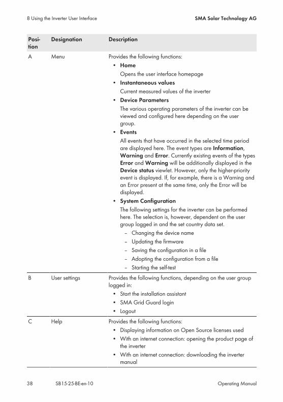
A Menu Provides the following functions:• HomeOpens the user interface homepage
• Instantaneous valuesCurrent measured values of the inverter
• Device ParametersThe various operating parameters of the inverter can beviewed and configured here depending on the usergroup.
• EventsAll events that have occurred in the selected time periodare displayed here. The event types are Information,Warning and Error. Currently existing events of the typesError and Warning will be additionally displayed in theDevice status viewlet. However, only the higher-priorityevent is displayed. If, for example, there is a Warning andan Error present at the same time, only the Error will bedisplayed.
• System ConfigurationThe following settings for the inverter can be performedhere. The selection is, however, dependent on the usergroup logged in and the set country data set.– Changing the device name– Updating the firmware– Saving the configuration in a file– Adopting the configuration from a file– Starting the self-test
B User settings Provides the following functions, depending on the user grouplogged in:• Start the installation assistant• SMA Grid Guard login• Logout
C Help Provides the following functions:• Displaying information on Open Source licenses used• With an internet connection: opening the product page ofthe inverter
• With an internet connection: downloading the invertermanual
8 Using the Inverter User Interface SMA Solar Technology AG
Operating ManualSB15-25-BE-en-1038

Posi-tion
Designation Description
D Status display The various areas display information on the current status ofthe PV system.• Device statusDisplays whether the inverter is currently in a fault-freeoperating state or whether there is an Error or Warningpresent.
• Current powerDisplays the power currently being generated by theinverter.
• Current consumptionDisplays the current consumption of the household if anenergy meter is installed in the PV system.
• YieldDisplays the energy yield of the inverter.
• ConsumptionDisplays the energy consumption of the household if anenergy meter is installed in the PV system.
• Feed-in managementDisplays whether the inverter is currently limiting its activepower.
E PV power and powerconsumption progres-sion
Temporal progression of the PV power and the power con-sumption of the household over the selected time period. Pleasenote, the power consumption will only be displayed if an en-ergy meter is installed in the PV system.
F Status bar Displays the following information:• Inverter serial number• Inverter firmware version• IP address of the inverter within the local network• User group logged in• Date and device time of the inverter
8.3 Changing the PasswordThe password for the inverter can be changed for both user groups. Furthermore, the user groupInstaller can change the password for the user group User as well as its own password.
8 Using the Inverter User InterfaceSMA Solar Technology AG
Operating Manual 39SB15-25-BE-en-10

PV systems registered in a communication productWith PV systems that are registered in a communication product (e.g. Sunny Portal,Sunny Home Manager), you can also assign a new password for the user group Installer viathe communication product. The password for the user group Installer is also the systempassword for the PV system. If you assign a password for the user group Installer on theinverter user interface that does not correspond to the system password, the inverter can nolonger be reached by the communication product.• Ensure that the password for the user group Installer is the same as the system passwordin the communication product.
Procedure:1. Call up the inverter user interface (see Section 8.1, page 34).2. Log in as Installer or User.3. Call up the menu Device Parameters.4. Select [Edit parameters].5. In the parameter group User Rights > Access Control change the password of the desireduser group.
6. Select [Save all] to save the changes.
8.4 Forgotten PasswordIf you have forgotten the password for the inverter, you can unlock the inverter with a PersonalUnlocking Key (PUK). For each inverter, there is one PUK for each user group (User and Installer).Tip: With PV systems in Sunny Portal, you can also assign a new password via Sunny Portal for theuser group Installer. The password for the user group Installer is the same as the systempassword in Sunny Portal.
Procedure:1. Request PUK (application form available at www.SMA-Solar.com).2. Call up the inverter user interface (see Section 8.1, page 34).3. Enter the PUK instead of the password when registering on the user interface.4. Call up the menu Device Parameters.5. Select [Edit parameters].6. In the parameter group User Rights > Access Control change the password of the desireduser group.
7. Select [Save all] to save the changes.
PV Systems in Sunny PortalThe password for the user group Installer is also the system password for the PV system inSunny Portal. Changing the password of the user group Installer can lead to the inverter nolonger being able to be reached by Sunny Portal.• Assign the changed password of the user group Installer as the new system password inSunny Portal (see the Sunny Portal user manual at www.SMA-Solar.com).
8 Using the Inverter User Interface SMA Solar Technology AG
Operating ManualSB15-25-BE-en-1040

9 Configuration
9.1 Configuration ProcedureOnce you have commissioned the inverter, you may have to adjust various inverter settings. Thissection describes the procedure for configuration and gives an overview of the steps you mustperform in the prescribed order.
No configuration via Sunny ExplorerSunny Explorer does not support the configuration of inverters with integrated web server andtheir own user interface. The inverter can be detected via Sunny Explorer, however it isexpressly not recommended to use Sunny Explorer to configure this inverter. SMA SolarTechnology AG does not accept liability for missing or incorrect data and possibly resultingyield losses.• Use the integrated inverter user interface for the configuration of the inverter.
Procedure See1. Perform initial configuration with the help of the installation
assistant.Section 9.2, page 41
2. In order to receive control commands of the grid operatorvia SMA Speedwire/Webconnect for PV systems in Italy,set the parameters.
Section 9.4, page 42
3. If the inverter is installed in an IT network or another gridconfiguration where deactivation of the grounding con-ductor monitoring is required, deactivate the groundingconductor monitoring.
Section 9.5, page 43
4. For partially shaded PV modules and depending on thegiven shading situation, you should set the interval atwhich the inverter optimizes the MPP of the PV system.
Section 9.6, page 43
5. Make further settings where necessary.
9.2 Starting the Installation Assistant
The installation assistant leads you step-by-step through the steps necessary for the initialconfiguration of the inverter.
Requirements: When configuring after completion of the first ten operating hours, the SMA Grid Guard codemust be available (see "Application for SMA Grid Guard Code" at www.SMA-Solar.com).
Procedure:1. Call up the inverter user interface (see Section 8.1, page 34).2. Log in as Installer.
9 ConfigurationSMA Solar Technology AG
Operating Manual 41SB15-25-BE-en-10

3. On the right-hand side of the menu bar, select the menu User Settings (see Section 8.2"Design of the Inverter User Interface", page 37).
4. In the subsequent context menu, select [Start the installation assistant]. The installation assistant dialog opens.
9.3 Starting the Self-Test (For Italy Only)
The self-test is only required for inverters to be commissioned in Italy. The Italian standard requiresthat all inverters feeding into the utility grid are equipped with a self-test function in accordance withCEI 0-21. During the self-test, the inverter will consecutively check the reaction times forovervoltage, undervoltage, maximum frequency and minimum frequency.The self-test changes the upper and lower disconnection values for each protective function on alinear basis for frequency monitoring and voltage monitoring. As soon as the measured valueexceeds the permitted disconnection threshold, the inverter disconnects from the utility grid. In thisway, the inverter determines the reaction time and checks itself.After the self-test has been completed, the inverter automatically switches back to feed-in operation,resets the original disconnection conditions and connects to the utility grid. The test takesapproximately three minutes.
Requirements: The country data set of the inverter must be set to CEI 0-21 internal.
Procedure:1. Call up the inverter user interface (see Section 8.1, page 34).2. Log in as Installer.3. Select the menu System Configuration.4. Select [Settings]. A context menu opens.
5. Select [Start self-test] in the context menu.6. Observe the instructions shown in the dialog and save the report of the self-test, if necessary.
9.4 Activating the Receipt of Control Signals (Only forItaly)
In order for PV systems in Italy to receive control commands from the grid operator, set thefollowing parameters. Some function-sensitive parameters can only be viewed by qualified personsand can only be changed by qualified persons.
9 Configuration SMA Solar Technology AG
Operating ManualSB15-25-BE-en-1042

The basic procedure for changing operating parameters is explained in another section (seeSection 9.14 "Changing Operating Parameters", page 46).
Parameter Value/range Resolution DefaultApplication ID 0 … 16384 1 16384
GOOSE-Mac address 01:0C:CD:01:00:00…01:0C:CD:01:02:00
1 01:0C:CD:01:00:00
Procedure:1. Select the parameter group External Communication > IEC 61850 configuration.2. In the field Application ID, enter the application ID of the grid operator gateway. You willreceive this value from your grid operator. You can enter a value between 0 and 16384. Thevalue 16384 indicates "deactivated".
3. In the field GOOSE-Mac address, enter the MAC address of the grid operator gateway fromwhich the inverter is to receive the control commands. You will receive this value from your gridoperator.
The receipt of control signals from the grid operator is activated.
9.5 Deactivating Grounding Conductor Monitoring
If the inverter is to be installed in an IT network or another grid configuration in which deactivationof the grounding conductor monitoring is required, deactivate the grounding conductor monitoringas follows.The basic procedure for changing operating parameters is explained in another section (seeSection 9.14 "Changing Operating Parameters", page 46).
Procedure:• Set the parameter PE connection monitoring to Off.
9.6 Setting SMA OptiTrac Global Peak
For partially shaded PV modules, you should set the interval at which the inverter is to optimize theMPP of the PV system.The basic procedure for changing operating parameters is explained in another section (seeSection 9.14 "Changing Operating Parameters", page 46).
Procedure:• Select the parameter Cycle time of the OptiTrac Global Peak algorithm or
MPPShdw.CycTms and set the required time interval. The ideal time interval is usually sixminutes. This value should only be increased if the shading situation changes extremely slowly. The inverter optimizes the MPP of the PV system at the predetermined time interval.
9 ConfigurationSMA Solar Technology AG
Operating Manual 43SB15-25-BE-en-10

9.7 Saving the Configuration in a FileYou can save the current configuration of the inverter in a file. You can use this file as a databackup for this inverter and then import this file into this inverter again or another inverter toconfigure the inverter. When saving, only the device parameters will be saved, not the networkconfiguration or any passwords.
Procedure:1. Call up the inverter user interface (see Section 8.1, page 34).2. Log in as Installer or User.3. Select the menu System Configuration.4. Select [Settings]. A context menu opens.
5. In the context menu, select [Saving the configuration in a file].6. Follow the instructions in the dialog.
9.8 Adopting a Configuration from a File
To configure the inverter, you can adopt the configuration from a file. To be able to do this, youmust first save the configuration of another inverter in a file (see Section 9.7 "Saving theConfiguration in a File", page 44).
Requirements: The SMA Grid Guard code must be available (see "Application for SMA Grid Guard Code"at www.SMA-Solar.com).
Changes to grid-relevant parameters must be approved by the responsible grid operator.
Procedure:1. Call up the inverter user interface (see Section 8.1, page 34).2. Log in as Installer.3. Select the menu System Configuration.4. Select [Settings]. A context menu opens.
5. In the context menu, select [Adopting the configuration from a file].6. Follow the instructions in the dialog.
9.9 Updating the FirmwareYou can manually update the inverter firmware. To do this, proceed as follows.Tip: With PV systems that are registered in Sunny Portal, the inverter firmware is usually updatedautomatically. In certain circumstances, a manual update of the inverter firmware is, however,necessary.
9 Configuration SMA Solar Technology AG
Operating ManualSB15-25-BE-en-1044

Requirements: An update file with the current inverter firmware must be available. The update file is, forexample, available for download on the product page of the inverter at www.SMA-Solar.com.
Procedure:1. Call up the inverter user interface (see Section 8.1, page 34).2. Log in as Installer or User.3. Select the menu System Configuration.4. Select [Settings]. A context menu opens.
5. In the context menu, select [Updating the firmware].6. Follow the instructions in the dialog.
9.10 Integrating the Inverter into the NetworkRequirements: The inverter must be in operation. There must be a router with Internet connection in the local network of the system.
Procedure:1. Call up the inverter user interface (see Section 8.1, page 34).2. Log in as Installer.3. On the right-hand side of the menu bar, select the menu User Settings (see Section 8.2"Design of the Inverter User Interface", page 37).
4. In the subsequent context menu, select [Start the installation assistant].5. Perform the desired network configuration.
9.11 Setting the Date and Device TimeYou can set the date and the device time of the inverter.
Procedure:1. Call up the inverter user interface (see Section 8.1, page 34).2. Log in as Installer or User.3. In the status bar at the bottom, click on the date and the time.4. In the subsequent dialog, perform the desired settings for the date and device time.
9.12 Configuring the Energy Meter
You can add an energy meter to your PV system or replace an existing energy meter.
9 ConfigurationSMA Solar Technology AG
Operating Manual 45SB15-25-BE-en-10

Removing a detected energy meter from the PV systemIf only one energy meter is detected by the inverter, this will be added to the PV systemautomatically. Removal via the menu System Configuration is not possible in this case. Toremove the energy meter from the PV system, proceed as follows:• In the parameter group PV system communication > Measured values > Meter on
Speedwire set the parameter Serial Number to any number (e.g. 1) (see Section 9.14"Changing Operating Parameters", page 46). In this way, instead of the energy meterdetected, the PV system will add a fictitious energy meter to which the inverter can notestablish communication.
Procedure:1. Call up the inverter user interface (see Section 8.1, page 34).2. Log in as Installer.3. On the right-hand side of the menu bar, select the menu User Settings (see Section 8.2"Design of the Inverter User Interface", page 37).
4. In the subsequent context menu, select [Start the installation assistant].5. Select [Save and next] until you arrive in the menu Meter configuration.6. Add or replace the desired energy meter.
9.13 Configuring Feed-In Management
If required by the grid operator, the inverter can provide grid management services. You canconfigure these via the inverter feed-in management. Coordinate the configuration of the feed-inmanagement with your grid operator beforehand.
Procedure:1. Call up the inverter user interface (see Section 8.1, page 34).2. Log in as Installer.3. On the right-hand side of the menu bar, select the menu User Settings (see Section 8.2"Design of the Inverter User Interface", page 37).
4. In the subsequent context menu, select [Start the installation assistant].5. Select [Save and next] until you arrive in the menu Feed-in management.6. Configure the feed-in management as desired.
9.14 Changing Operating ParametersThe operating parameters of the inverter are set to certain values by default. You can change theoperating parameters to optimize the performance of the inverter.
9 Configuration SMA Solar Technology AG
Operating ManualSB15-25-BE-en-1046

This section describes the basic procedure for changing operating parameters. Always changeoperating parameters as described in this section. Some function-sensitive parameters can only beviewed by qualified persons and can only be changed by qualified persons by entering thepersonal SMA Grid Guard code.
No configuration via Sunny ExplorerSunny Explorer does not support the configuration of inverters with integrated web server andtheir own user interface. The inverter can be detected via Sunny Explorer, however it isexpressly not recommended to use Sunny Explorer to configure this inverter. SMA SolarTechnology AG does not accept liability for missing or incorrect data and possibly resultingyield losses.• Use the integrated inverter user interface for the configuration of the inverter.
Requirements: The changes to the grid-relevant parameters must be approved by the grid operator. When changing grid-relevant parameters, the SMA Grid Guard code must be available (see"Application for SMA Grid Guard Code" at www.SMA-Solar.com).
Procedure:1. Call up the inverter user interface (see Section 8.1, page 34).2. Log in as Installer or User.3. Call up the menu Device Parameters.4. Select [Edit parameters].5. Log in using the SMA Grid Guard code to change those parameters designated by a lock(only for installers):• On the right-hand side of the menu bar, select the menu User Settings (see Section 8.2"Design of the Inverter User Interface", page 37).
• In the subsequent context menu, select [SMA Grid Guard login].• Enter the SMA Grid Guard code and select [Login].
6. Change the desired parameters.7. Select [Save all] to save the changes.
9.15 Configuring the Country Data Set
By default, the inverter is set to a universally valid country data set. You can adjust the country dataset for the installation site retroactively.The basic procedure for changing operating parameters is explained in another section (seeSection 9.14 "Changing Operating Parameters", page 46).
Procedure:• Select the parameter Set country standard and set the required country data set.
9 ConfigurationSMA Solar Technology AG
Operating Manual 47SB15-25-BE-en-10

9.16 Switching the Dynamic Power Display OffAs standard, the inverter signals its power dynamically via the pulsing of the green LED. Whendoing so, the LED flashes on and off uniformly or is permanently lit at full power. The variousgradations are related here to the set active power limit of the inverter. If this display is not desired,switch this function off in accordance with the following procedure. Once this has been done, thegreen LED is only lit permanently to signalize feed-in operation.The basic procedure for changing operating parameters is explained in another section (seeSection 9.14 "Changing Operating Parameters", page 46).
Procedure:• In the parameter group Device > Operation, select the parameter Dynamic power
display via green LED and set this to Off.
9.17 Switching WLAN OffThe inverter is equipped with an activated WLAN interface as standard. If you do not want to useWLAN, you can switch the WLAN function off in accordance with the following procedure. Indoing so, you can switch the WLAN direct connection and the WLAN connection in the localnetwork on or off independently of each other. If you would like to switch the WLAN function offcompletely, you must switch off both the WLAN direct connection and the WLAN connection in thelocal network.The basic procedure for changing operating parameters is explained in another section (seeSection 9.14 "Changing Operating Parameters", page 46).
Switching on the WLAN function only possible via Ethernet connectionIf you switch off both the WLAN function for the WLAN direct connection and for the WLANconnection in the local network, access to the inverter user interface and therefore reactivationof the WLAN interface is only possible via an Ethernet connection.
Procedure:• To switch off the WLAN direct connection, select the parameter Soft-access-point is turned
on and set this to No.• To switch off the WLAN connection in the local network, select the parameter WLAN is
turned on and set this to No.
9.18 Switching WLAN OnIf you have switched the WLAN function for direct connection or for connection in the local networkoff, you can switch the WLAN function back on in accordance with the following procedure. Indoing so, you can switch the WLAN direct connection and the WLAN connection in the localnetwork on independently of each other.The basic procedure for changing operating parameters is explained in another section (seeSection 9.14 "Changing Operating Parameters", page 46).
Requirement: If the WLAN function was previously switched off completely, the inverter must be connectedto a computer or router via Ethernet.
9 Configuration SMA Solar Technology AG
Operating ManualSB15-25-BE-en-1048

Procedure:• To switch on the WLAN direct connection, in the parameter group PV system
communication > WLAN, select the parameter Soft-access-point is turned on and set thisto Yes.
• To switch on the WLAN connection in the local network, in the parameter group PV systemcommunication > WLAN, select the parameter WLAN is turned on and set this to Yes.
9 ConfigurationSMA Solar Technology AG
Operating Manual 49SB15-25-BE-en-10

10 Disconnecting the Inverter from Voltage Sources
Prior to performing any work on the inverter, always disconnect it from all voltage sources asdescribed in this section. Always adhere to the prescribed sequence.
Procedure:1. Disconnect the circuit breaker and secure it against reconnection.2. If an external DC load-break switch is installed, disconnect the external DC load-break switchfrom all voltage sources.
3. Set the DC load-break switch of the inverter to O.
4. Wait until the LEDs have gone out.5. Use a current clamp to ensure that no current is present in the DC cables.6. Release and remove all DC connectors. To dothis, insert a flat-blade screwdriver or an angledscrewdriver (blade width 3.5 mm) into one ofthe slide slots and pull the DC connectors out ina downward direction. Do not pull on the cable.
1
2
10 Disconnecting the Inverter from Voltage Sources SMA Solar Technology AG
Operating ManualSB15-25-BE-en-1050

7. Ensure that no voltage is present at the DCinputs on the inverter using a suitable measuringdevice.
8. Loosen the swivel nuts.9. Loosen the screws of the connection cap andremove the connection cap.
10. Use a suitable measuring device to check that no voltage is present at the AC connectorbetween L and N and between L and the grounding conductor. To do so, insert the test probe(maximum diameter: 2 mm) into each round opening of the connecting terminal plate.
11. Release and disconnect the AC connector usingthe sliders located on the side.
L N1
1
2
10 Disconnecting the Inverter from Voltage SourcesSMA Solar Technology AG
Operating Manual 51SB15-25-BE-en-10

11 Technical DataDC Input
SB 1.5-1VL-40 SB 2.5-1VL-40Maximum DC power at cos φ = 1 1,600 W 2,650 W
Maximum input voltage 600 V 600 V
MPP voltage range 160 V to 500 V 260 V to 500 V
Rated input voltage 360 V 360 V
Minimum input voltage 50 V 50 V
Start input voltage 80 V 80 V
Maximum input current 10 A 10 A
Maximum short-circuit current* 18 A 18 A
Maximum reverse current from the in-verter in the system for max. 1 ms
0 A 0 A
Number of independent MPP inputs 1 1
Overvoltage category in accordancewith IEC 60664-1
II II
* In accordance with IEC 62109-2: ISC PV
AC Output
SB 1.5-1VL-40 SB 2.5-1VL-40Rated power at 230 V, 50 Hz 1,500 W 2,500 W
Maximum apparent AC power atcos φ = 1
1,500 VA 2,500 VA
Rated grid voltage 230 V 230 V
Nominal AC voltage 220 V / 230 V / 240 V 220 V / 230 V / 240 V
AC voltage range* 180 V to 280 V 180 V to 280 V
Nominal AC current at 220 V 7 A 11 A
Nominal AC current at 230 V 6.5 A 11 A
Nominal AC current at 240 V 6.25 A 10.5 A
Maximum output current 7 A 11 A
Total harmonic distortion of the outputcurrent with total harmonic distortionof the AC voltage < 2%, and ACpower > 50% of the rated power
≤3 % ≤3 %
11 Technical Data SMA Solar Technology AG
Operating ManualSB15-25-BE-en-1052
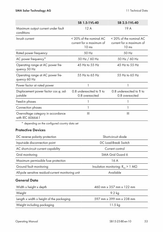
SB 1.5-1VL-40 SB 2.5-1VL-40Maximum output current under faultconditions
12 A 19 A
Inrush current < 20% of the nominal ACcurrent for a maximum of
10 ms
< 20% of the nominal ACcurrent for a maximum of
10 ms
Rated power frequency 50 Hz 50 Hz
AC power frequency* 50 Hz / 60 Hz 50 Hz / 60 Hz
Operating range at AC power fre-quency 50 Hz
45 Hz to 55 Hz 45 Hz to 55 Hz
Operating range at AC power fre-quency 60 Hz
55 Hz to 65 Hz 55 Hz to 65 Hz
Power factor at rated power 1 1
Displacement power factor cos φ, ad-justable
0.8 underexcited to 1 to0.8 overexcited
0.8 underexcited to 1 to0.8 overexcited
Feed-in phases 1 1
Connection phases 1 1
Overvoltage category in accordancewith IEC 60664-1
III III
* depending on the configured country data set
Protective Devices
DC reverse polarity protection Short-circuit diode
Input-side disconnection point DC Load-Break Switch
AC short-circuit current capability Current control
Grid monitoring SMA Grid Guard 6
Maximum permissible fuse protection 16 A
Ground fault monitoring Insulation monitoring: Riso > 1 MΩ
All-pole sensitive residual-current monitoring unit Available
General Data
Width x height x depth 460 mm x 357 mm x 122 mm
Weight 9.2 kg
Length x width x height of the packaging 597 mm x 399 mm x 238 mm
Weight including packaging 11.5 kg
11 Technical DataSMA Solar Technology AG
Operating Manual 53SB15-25-BE-en-10

Climatic category in accordance withIEC 60721-3-4
4K4H
Environmental category Outdoors
Pollution degree outside the inverter 3
Pollution degree inside the inverter 2
Operating temperature range −40°C to +60°C
Maximum permissible value for relative humid-ity, non-condensing
100 %
Maximum operating altitude above mean sealevel
3,000 m
Noise emission, typical < 25 dB
Power loss in night mode 2 W
Maximum data volume per inverter with Speed-wire/Webconnect
550 MB/month
Additional data volume when using the Sun-ny Portal live interface
600 kB/hour
WLAN range in free-field conditions 100 m
Quantity maximum detectable WLAN networks 32
Topology Transformerless
Cooling method Convection
Degree of protection in accordance withIEC 60529
IP65
Protection class in accordance with IEC 62103 I
Grid configurations TN-C, TN-S, TN-CS, TT (if VN_PE < 30 V), IT, DeltaIT, split phase
National standards and approvals, as per04/2015*
AS 4777, C10/11/2012, CEI 0-21,EN 50438:2013, G83/2, NEN-EN50438,VDE-AR-N 4105, VFR2014, DIN EN 62109-1,
IEC 62109-2* IEC 62109-2: In order to meet the requirements of this standard, there must be a link to Sunny Portalwith the fault alert via e-mail activated.
Climatic Conditions
Installation in accordance with IEC 60721-3-4, Class 4K4H
Extended temperature range −40°C to +60°C
11 Technical Data SMA Solar Technology AG
Operating ManualSB15-25-BE-en-1054

Extended humidity range 0 % … 100 %
Extended air pressure range 79.5 kPa to 106 kPa
Transport in accordance with IEC 60721-3-4, Class 2K3
Extended temperature range −25°C to +70°C
Equipment
DC connection SUNCLIX DC connector
AC connection Spring-cage terminal
Speedwire interface As standard
Webconnect interface As standard
WLAN As standard
DC Load-Break Switch
Electrical endurance in the event of short circuit,at nominal current of 10 A
At least 50 switching operations
Maximum switching current 35 A
Maximum switching voltage 800 V
Maximum PV power 11 kW
Torques
Screws wall mounting Hand-tight
Screws connection cap 3.5 Nm
SUNCLIX swivel nut 2.0 Nm
AC swivel nut Hand-tight
Network swivel nut Hand-tight
Additional grounding terminal 6.0 Nm
Data Storage Capacity
Energy yields in the course of the day 63 days
Daily yields 30 years
Event messages for users 1,000 events
Event messages for installers 1,000 events
11 Technical DataSMA Solar Technology AG
Operating Manual 55SB15-25-BE-en-10

Efficiency
SB 1.5-1VL-40 SB 2.5-1VL-40Maximum efficiency, ηmax 97.2 % 97.2 %
European weighted efficiency, ηEU 96.1 % 96.7 %
11 Technical Data SMA Solar Technology AG
Operating ManualSB15-25-BE-en-1056

12 ContactIf you have technical problems with our products, please contact the SMA Service Line. We needthe following information in order to provide you with the necessary assistance:
Australia SMA Australia Pty Ltd.SydneyToll free for Australia:1800 SMA AUS(1800 762 287)International: +61 2 9491 4200
BelgienBelgiqueBelgiëLuxemburgLuxembourgNederland
SMA Benelux BVBA/SPRLMechelen+32 15 286 730
ArgentinaBrasilChilePerú
SMA South America SPASantiago+562 2820 2101
ČeskoMagyarországPolskaRomâniaSlovensko
SMA Central & EasternEurope s.r.o.Praha+420 235 010 417
DanmarkDeutschlandÖsterreichSchweiz
SMA Solar Technology AGNiestetalSMA Online Service Center:www.SMA.de/ServiceSunny Boy, Sunny Mini Central,Sunny Tripower:+49 561 9522‑1499Monitoring Systems (Kommunika-tionsprodukte):+49 561 9522‑2499Fuel Save Controller (PV-Diesel-Hybridsysteme):+49 561 9522-3199Sunny Island, Sunny Backup, Hy-dro Boy: +49 561 9522-399Sunny Central:+49 561 9522-299
France SMA France S.A.S.LyonSunny Boy, Sunny Mini Central,Sunny Tripower:+33 472 09 04 40Monitoring Systems:+33 472 09 04 41Sunny Island :+33 472 09 04 42Sunny Central :+33 472 09 04 43
EspañaPortugal
SMA Ibérica Tecnología Solar,S.L.U.Barcelona+34 935 63 50 99
India SMA Solar India Pvt. Ltd.Mumbai+91 22 61713888
12 ContactSMA Solar Technology AG
Operating Manual 57SB15-25-BE-en-10

South Africa SMA Solar Technology SouthAfrica Pty Ltd.Centurion (Pretoria)08600 SUNNY(08600 78669)International:+27 (12) 622 3000
ΕλλάδαΚύπροςKıbrısБългария
SMA Hellas AEΑθήνα801 222 9 222International:+30 212 222 9 222
Italia SMA Italia S.r.l.Milano+39 02 8934-7299
UnitedKingdom
SMA Solar UK Ltd.Milton Keynes+44 1908 304899
SMA Solar (Thailand) Co., Ltd.
+66 2 670 6999
대한민국 SMA Technology Korea Co.,Ltd.서울+82-2-520-2666
Middle East LLC
,2345%6!78%
9:;*<+%,='3)>+%SMA Middle East LLC
/01,234 9:;
+971 2 234-6177
Other countries International SMA Service LineNiestetalToll free worldwide:00800 SMA SERVICE(+800 762 7378423)
12 Contact SMA Solar Technology AG
Operating ManualSB15-25-BE-en-1058


SMA Solar Technology
www.SMA-Solar.com