Embed Size (px)
Citation preview

MIG/MAGPLASMAOPERAT ING MANUAL
Plasma Cutter 300


Plasma Cutter 300 General information’s: These operating instructions are intended to ensure safe and efficient work with this cutting unit. Prior to initial operation of the unit, read the instructions carefully. The information contained in this manual should be made available to all operational staff. These instructions should always be kept ready-to-hand, near the machine. Electromagnetic compatibility EMC (IEC 60974-10): WARNING: This class A cutting unit is not provided for use in housing areas, where the electric power supply comes from a public low voltage supply. It may possible, that through wire fixed or radiate disturbances, it isn’t easy to guarantee electromagnetic compatibility in these areas. INFORMATION: The user is responsible for the trouble, which the machine generates during the operation. He must rate and consider possible electromagnetic problems in the neighborhood. Warranty: INFORMATION: Improper repair or servicing, technical modifications of the product, unauthorized, not strictly from JÄCKLE GmbH permitted modifications, as well as carelessness at the installation or use, or the nonobservance of care in own affairs lead to the extinction of every warranty.

Plasma Cutter 300
DECLARATION OF CONFORMITY within the meaning of EC recommendation EMC 89/336/EEC, appendix I respectively of EC recommendation 73/23/EEC, appendix III B Manufacturer: Jäckle Schweiß- und Schneidtechnik GmbH
Riedweg 4 D – 88339 Bad Waldsee Germany
We declare, that below mentioned current source corresponds to the safety requirements of the recommendations. Name of unit: Plasma Cutting System Type of unit: Plasma Cutter 300 Relevant EMC recommendation 89/336/EEC, EC recommendations: modified by recommendation 92/31/EEC Low-voltage recommendation 73/23/EEC, modified by recommendation 93/68/EEC Applied EN 60 974-10 harmonised standards: EMC product standard for arc welding equipment Especially: EN 60974-1 Arc welding equipment – Welding power sources Jäckle Schweiß- und Schneidtechnik GmbH
Reinhard Jäckle
Plasma Cutter 300
Contents Page 1. Some general information about plasma cutting ..........................................................1 2. Safety Requirements ....................................................................................................2 3. Brief description............................................................................................................5 4. Technical Data..............................................................................................................6 5. Control Elements ..........................................................................................................7 6. Initial operation .............................................................................................................8 7. Preparations for cutting ..............................................................................................10 8. Cutting ........................................................................................................................11 9. Stand-bye mode / fan Control system ........................................................................12 10. Maintenance and safety check ...............................................................................13 11. Functional description of the control PCB...............................................................14 12. Error messages of the control PCB.........................................................................15 13. Trouble-Shooting ....................................................................................................16 14. Spare Parts .............................................................................................................17 15. Circuit diagram........................................................................................................23 Pictures: Picture 5.1 Control Elements ...............................................................................................7 Picture 10.1 View on the PCB PL 3 ...................................................................................14 Picture 14.1 Frontview .......................................................................................................17 Picture 14.2 Sideview ........................................................................................................19 Picture 14.3 Inside.............................................................................................................21 Picture 14.4 Air unit ...........................................................................................................22 Circuit diagram...................................................................................................................23 Subject to mistakes and technical modifications Version 2.00 December 2008

Plasma Cutter 300
Operating Manual Page 1
1. Some general information about plasma cutting
1.1 Operating principle In a plasma torch, the air is heated to an extremely high temperature through an electric arc, thus forming an electroconductive plasma which allows the cutting current to flow from the electrode to the workpiece. The small-size bore of the cutting nozzle constricts the cutting current and produces a strongly concentrated plasma cutting jet. It causes the metal to melt very rapidly, and its highly kinetic energy ejects the molten metal from the kerb. A clean, clear cut is the result. 1.2 Advantages Time saving due to high cutting speed in cutting thin sheet metal, if compared to oxy-fuel gas cutting, nibbling or sawing. Heat build-up is kept at a reduced level due to the high cutting speed and a strongly concentrated plasma arc. Therefore, warping of the workpiece is very unlikely. Ease of operation. Low Operating expenses due to compressed air being used as plasma gas. Low energy - high efficiency. 1.3 Field of Application The plasma cutting method is applicable on almost any conductive metal, i.e. high alloy chrome nickel steels, any hardened and unhardened tool steels, constructional steels, non-ferrous metals like aluminium and its compounds, brass, copper and even grey cast iron.
Plasma Cutter 300
Operating Manual Page 2
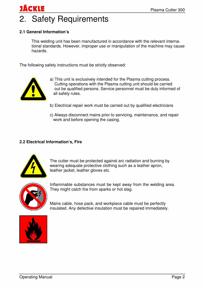
2. Safety Requirements 2.1 General Information’s This welding unit has been manufactured in accordance with the relevant interna- tional standards. However, improper use or manipulation of the machine may cause hazards. The following safety instructions must be strictly observed:
a) This unit is exclusively intended for the Plasma cutting process. Cutting operations with the Plasma cutting unit should be carried out be qualified persons. Service personnel must be duly informed of all safety rules.
b) Electrical repair work must be carried out by qualified electricians
c) Always disconnect mains prior to servicing, maintenance, and repair work and before opening the casing.
2.2 Electrical Information’s, Fire
The cutter must be protected against arc radiation and burning by wearing adequate protective clothing such as a leather apron, leather jacket, leather gloves etc. Inflammable substances must be kept away from the welding area. They might catch fire from sparks or hot slag. Mains cable, hose pack, and workpiece cable must be perfectly insulated. Any defective insulation must be repaired immediately.
Plasma Cutter 300
Operating Manual Page 3
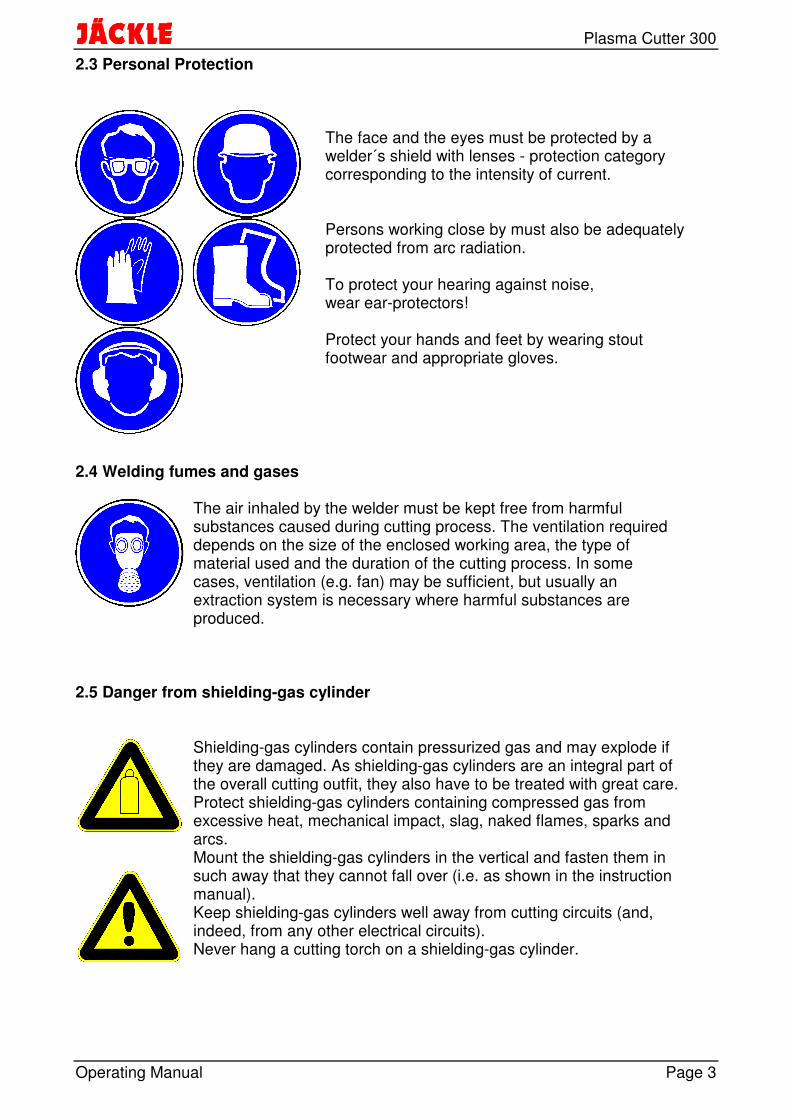
2.3 Personal Protection
The face and the eyes must be protected by a welder´s shield with lenses - protection category corresponding to the intensity of current. Persons working close by must also be adequately protected from arc radiation. To protect your hearing against noise, wear ear-protectors! Protect your hands and feet by wearing stout footwear and appropriate gloves.
2.4 Welding fumes and gases
The air inhaled by the welder must be kept free from harmful substances caused during cutting process. The ventilation required depends on the size of the enclosed working area, the type of material used and the duration of the cutting process. In some cases, ventilation (e.g. fan) may be sufficient, but usually an extraction system is necessary where harmful substances are produced.
2.5 Danger from shielding-gas cylinder
Shielding-gas cylinders contain pressurized gas and may explode if they are damaged. As shielding-gas cylinders are an integral part of the overall cutting outfit, they also have to be treated with great care. Protect shielding-gas cylinders containing compressed gas from excessive heat, mechanical impact, slag, naked flames, sparks and arcs. Mount the shielding-gas cylinders in the vertical and fasten them in such away that they cannot fall over (i.e. as shown in the instruction manual). Keep shielding-gas cylinders well away from cutting circuits (and, indeed, from any other electrical circuits). Never hang a cutting torch on a shielding-gas cylinder.

Plasma Cutter 300
Operating Manual Page 4
2.6 EMC and safety inspection Apart from the instructions given in this operating manual, the general safety standards, in particular the rules for prevention of accidents must be observed. The rules contain additional information’s about the prevention of radiation, smoke, combustion, electric shock, fire and explosion.
The rules are:
BGV A3 (electrical installations and operating supplies) and
BGR 500 chap. 2-26 (welding, cutting and related working processes).
Furthermore, we point out that in some operative ranges where, despite the observ- ance of radiation limits, this welding unit can cause electromagnetic interferences which are the responsibility of the user. This means that in the domain of hospitals, for instance, the function of electro- medical units, data-processing equipment and the like (ECG, PC etc.) may be impaired. Before putting the welding unit into service, please make sure to inform the autho- rities in charge of the above mentioned equipment. If you wish to use the cutting unit in domestic areas, special precautions have to be taken as well. Adequate assistance in assessing the operative range and minimizing electro- magnetic interferences (e.g. use of screening lines) may be obtained from the Electromagnetic Compatibility Standards for Arc Welding Systems. EN 60 974-10 (Electromagnetic compatibility EMC) Safety inspection: The owner/operator is obliged to have a safety inspection performed on the machine at least once every 12 months. Observe the relevant national and international standards and directives in connection with the safety inspection. More detailed information on safety inspections and calibration is available from your regional or national service centre, who will be pleased to provide you with copies of the necessary documents upon request e.g.: EN 60974-4 (Safety, maintenance and inspection of arc welding equipment in use)

Plasma Cutter 300
Operating Manual Page 5
3. Brief description The Plasma Cutting Unit Plasma Cutter 300 has been developed in robust technology. It excels in multipurpose application both for manual cutting operations and in combina-tion with automatic or robot-operated cutting processes. Its Operating principle is characterised by the following: Compressed air as plasma gas for the plasma torch A high-grade filter welding regulator is standard equipment on this unit. The finely filtered, pressure-controlled air expands in the plasma torch body and serves as plasma gas. Water cooling system To protect the torch body against high thermic load, the machine has an high efficiency water cooling system. Inside torch connection for the plasma torch All connections are comfortable placed behind a flap. HF-ignited pilot arc. A pilot arc which is initiated by a high-frequency spark starter ensures reliable ignition of the cutting arc even on lacquered workpieces. In addition, this appliance is suited for automatic cutting processes. Automatic cutting process via Control board. All important function are available at the Remote Control socket. Safety cut-out. In the event of a pilot-arc failure, the current source switches off after approx. 2 seconds to protect the operator from a build-up of no-load voltage. Service friendly design All components are Easy to change.

Plasma Cutter 300
Operating Manual Page 6
4. Technical Data Supply voltage 3-phase 400 V, 50 Hz Max. power draw 105 kVA Fuse 125 A slow Set-point range 100A / 200A / 300A Max. open-circuit voltage 330 V 100 % duty cycle 300 A / 200 V Max. cutting thickness, quality cut 65 mm severance cut 100 mm System of protection IP 22 Insulation class H (180° C) Type of cooling F Dimensions L x W x H (mm) 1140 x 575 x 1070 Weight 362 kg Compressed-air supply 3,5 bar (depending on torch used) 40 l/min
Authorized for welding under increased electrical hazard
Manufactured in acc. with European Standards EN 60 974-1 und EN 60 974-10

Plasma Cutter 300
Operating Manual Page 7
5. Control Elements
Picture 5.1 Control Elements
1 Main switch Position "O": unit is switched off. Position "I": unit is switched on 2 Control lamp ‘mains’ is lit when unit is switched on. 3 Control lamp source active is lit when torch trigger is pressed. 4 Compressed-air fault indicator lights up if there is insufficient supply of compressed air or if the working pressure has been set too low (<3,0 bar). No starting of the arc via torch trigger possible. After elimination of the deficiency, the plant will be operable again. Temperature fault indicator lights up if the current source is overheated. No starting of the arc via torch trigger possible. With the fan running, the unit will be operable again after approx. 5 min. 5 Weld grade switch
sets the cutting current to 100A, 200A or 300A. 6 Compressed air gauge shows the air pressure after the filter pressure reducer
7 Compressed air Control knob To adjust the compressed air shown on the gauge (6) 8 Workpiece connecting socket

Plasma Cutter 300
Operating Manual Page 8
6. Initial operation 6.1 Installation of the cutting unit When putting the unit in place, please make sure there is sufficient space for inlet and outlet cooling air so that the rated duty cycle will be attained. The unit should neither be exposed to moisture not to the plasma arc or the spark ray caused by grinding work. 6.2 Mains connection To be carried out only by a qualified electrician! Connect mains plug to mains cable as specified on the rating plate. The yellow-green lead is provided for PE earth conductor. The three phases (black, brown, and blue) may be connected to L1, L2, and L3 at random. 6.3 Compressed-air connection By means of the rapid action hose coupling provided at the rear of the unit. Take care that there is always an adequate supply of compressed air of the specified pressure. Moreover, the air should be free of oil or water. 6.4 Connection to workpiece Connect workpiece with workpiece cable to corresponding socket. Pinch workpiece termi-nal to workpiece, choosing an appropriate spot without paint or rust for good conductivity.

Plasma Cutter 300
Operating Manual Page 9
6.5 Connections for plasma torch or Plasmaignitionbox • Open the flap in the right side panel by turning the knob left. • Put the torch connections through the opening in the front into the connection box
inside. Connect the cables with the isolated screw fittings G 3/8 and M6. The connections must be fixed.
• Connect the Control cable in any order into the flat blade sockets. • Close the flap and turn the knob right.
Fuse
F13,15AT
F23,15AT
Rotaryswitch
Plasmaignition-box
On Off
Security flap switch
Socket for the torch trigger(Flat blade socket 6,3mm)
Compressed air connection G 1/4
Connection for pilot current M6
Torch connection for cutting current G 3/8 and water return flow
Water forward flow ‘blue’ DN 5
Hand-torch
Machine-torch
10-pole Connection for Plasmaignitionbox PZB 21(Option)
6.6 Directions for water-cooled torches: Water-cooled torches The torch is cooled by an integrated low-noise pump-circulated water-cooling system. The water tank should be about full, and it is advised to Check the water level after changing the torch.
− In order to protect the cooling-system from damage it is necessary to use only antifreezer BTC-15 from Binzel.
− It is not allowed to use normal antifreezer (e.g. Glycol), because hereby it is possible that the pump stucks and get damaged!
− Do not operate the pump without any water, because the liquid also serves as a grease for the pump and the gliding joint rings!
More details see Chapter 9.

Plasma Cutter 300
Operating Manual Page 10
7. Preparations for cutting 7.1 Regulation of cutting current Set the cutting current dependant to the material and thickness of the workpiece. 7.2 Torch equipment Select the correct plasma nozzle according to the table below. If the torch is fitted with an oversized plasma nozzle, the performance and cutting quality will be impaired. An under-sized tip bore will overload and destroy the plasma nozzle.
cutting current 100 A 200 A 300 A
plasma nozzle ∅ 1,5 ∅ 2,0 ∅ 2,0
When replacing a worn part, Check for tight fit. The plasma nozzle and the electrode are wearing parts. A plasma nozzle with a
gravely burnt bore and an electrode exhibiting a deep penetration crater will degrade the ignition characteristics and thus the cutting quality. The parts need to be exchanged.
7.3 Regulation of compressed air Set master switch to „I“; Control lamp ‘mains’ is lit. Unlock the pressure reducer by pulling the Control knob upwards. Set the working pres-sure according to the torch manufacturer’s specification. The working pressure must be regulated at flowing air (press compressed-air test key).
Plasma Cutter 300
Operating Manual Page 11
8. Cutting 8.1 Pilot arc ignition Bring the nozzle of the cutting torch to the starting point of the cut to be executed. Press torch trigger. After a short preweld gas flow time the pilot arc is ignited, and at the instant of the pilot arc impacting the workpiece, the cutting arc is formed. In the event of a cutting arc failure, the pilot arc is switched off after approx. 5 sec.
Repeated ignition of the pilot arc without actually initiating a cutting process should be avoided. An overload of the pilot arc resistance might occur, resulting in unnecessary wear of the torch parts.
8.2 Cutting In a hand-operated cutting process, move the torch with light contact over the workpiece at a constant speed. For achieving an optimum cut, make it a point to keep the right cutting speed correspon-ding with material thickness. If the cutting speed is too low, a blunt cutting edge will be the result because of the unduly high thermal input. Optimum cutting speed becomes apparent when the cutting jet slightly slopes backwards. At the instant of releasing the torch trigger, the plasma jet is extinguished and the current source cut off. The gas is post-flowing for approx. 1 minute to cool the torch. Overshooting the workpiece at pressed torch trigger will initiate the same procedure.
The machine must not be switched off during gas post-flow. Danger of torch damage by overheating!
In hand-operated hole-piercing, the hand cutter must be held in an inclinded position and then slowly brought to a vertical position to avoid the formation of spatter.
In machine-operated hole-piercing, bring the cutting nozzle of the machine torch to ap-prox. 7 - 8 mm distance to the workpiece. Then slowly approach to approx. 4 mm dis-tance.
Plasma Cutter 300
Operating Manual Page 12
9. Stand-bye mode / fan Control system The machine has 2 separate fans and a water pump. To reduce the noise of the machine, the components are only used when they are necessary. If the machine is not in use, all components are switched off. The machine is in stand-bye mode. Another advantage is the reduction of the pollution inside the machine. If the torch trigger is pressed, the water pump and the fans for the water cooling are starting to cool the torch. At the end of the cutting, the water system is running for 1 Minute to cool all components. After this, the cooling system is switching off. The fan for the power unit is separately sensor controlled. If the power unit is getting warm, the fan starts the cooling until the temperature is low enough. Under bad conditions it is possible, that the machine is getting to hot. In this case, the machine switch off and the Temperature fault indicator LED (Chap. 5-4) is flashing. With the fan running, the unit will be operable again after a few minutes.

Plasma Cutter 300
Operating Manual Page 13
10. Maintenance and safety check This unit should be serviced in regular intervals dependent on Operating times and working place conditions.
Before opening the machine switch off the plug!
- Check filter pressure reducer unit. Change cartridge, if required.
- Clean unit from inside by air-blasting according to degree of soiling. Attention: This Welding unit has to be safety checked every year by JÄCKLE Company or another special qualified electrician according to the harmonized standard IEC 60974 – 4 Safety, maintenance and inspection of arc welding equipment in use

Plasma Cutter 300
Operating Manual Page 14
11. Functional description of the control PCB
1
25V
BT OK
Picture 10.1 View on the PCB PL 3 The components in the grey fields have the following functions: • The LED D2 ‚5V‘ indicates the correct voltage on the PCB. • The LED D3 ‚OK‘ shows the normal function of the microprocessor. • The LED D4 ‚BT‘ shows the function of the torch trigger and the possible errors. They
are described in the next chapter ‘error messages’. • The LED’s D5 ‚Gas‘‚ D6 ‚Netz‘ and, D7 ‚Pilot‘ are illuminated, when the relay next to
the led is switched on by the microprocessor.

Plasma Cutter 300
Operating Manual Page 15
12. Error messages of the control PCB The control PCB has the possibility to find some errors in the working cycle. These errors are shown below: Errors in the machine: The LED D4 ‚BT‘ indicates why the microprocessor can not turn on the machine or why the machine is turned off. The LED D4 ‚BT‘ shows the errors by flashing. There are 2 normal- and 4 error states: Number of flashes Description
Normal functions: no light Torch trigger is not pressed permanent light Torch trigger is pressed
Error functions: 1x flash The cutting transformer has turned off, no cutting current 2x flash The reed contact has turned off, no cutting current 3x flash Reed contact is faulty, machine can not turn on 4x flash Pilot time longer than 2 seconds, safety turn off Every flashing sequence repeats after a short interrupt. The error message (led flashing) is shown until the torch trigger is pressed again. In normal function, the PCB always shows one of the possibilities in the error table. Errors in the microprocessor: If the microprocessor himself has a problem, the LED D3 ‚OK‘ has no light or a permanent light. In normal function, the LED flashes with a frequency of 1Hz.

Plasma Cutter 300
Operating Manual Page 16
13. Trouble-Shooting
Malfunction/error Cause Remedy
mains fuse has been tripped
Check mains fuse; if required, increase fuse protection,
mains cable interruption Check mains cable
mains connected and master switch in pos.“I“ /‘mains’ Control lamp is not lit
fuse defective change fuse, see also Chapter 15 circuit diagram
Torch trigger is pressed down - no function (no air)
imperfect assembly of torch head elements(safety cut-out)
Check torch head
torch trigger defective Check torch trigger
torch Control line interruption
Check torch Control line
fault indicators for compressed air, temperature or safety cover are lit
see Chapter 5 ‘Control elements’
one mains phase not connected (mains fuse has been tripped, interrupted lead of mains cable)
Check mains fuse Pressing of torch trigger actuates pilot contactor, however, total failure of the pilot arc or interruption of the pilot arc
excessive working pressure see Chapter 6.3 ‘Regulation of compressed air’
Permanent air flow, no HF ignition
Machine is switched into external plasmabox mode without a plasmbox
Switch the rotary switch (chap. 6.5) to plasmaignitionbox ‘Off’
Pilot arc is available / however, total failure of
one mains phase not connected
Check mains fuse Check mains cable
cutting arc earth cable not connected or without contact to workpiece due to impurities (paint etc.)
clamp earth cable to workpiece or improve contact
fault indicator is lit see Chapter ‘Control elements’
defective torch elements Check / exchange torch elements
insufficient supply of compressed air
see Chapter 6.3 ‘Regulation of compressed air’
cutting arc available, however, bad cut quality/ insufficient cutting performance
wrong plasma nozzle fitted on torch
see Chapter 7 ’Torch equipment’
wear of the plasma nozzle or electrode
Check / exchange plasma nozzle / electrode
Cutting arc switch-off insufficient cutting speed see Chapter 8.2 ‘Cutting’

Plasma Cutter 300
Operating Manual Page 17
14. Spare Parts
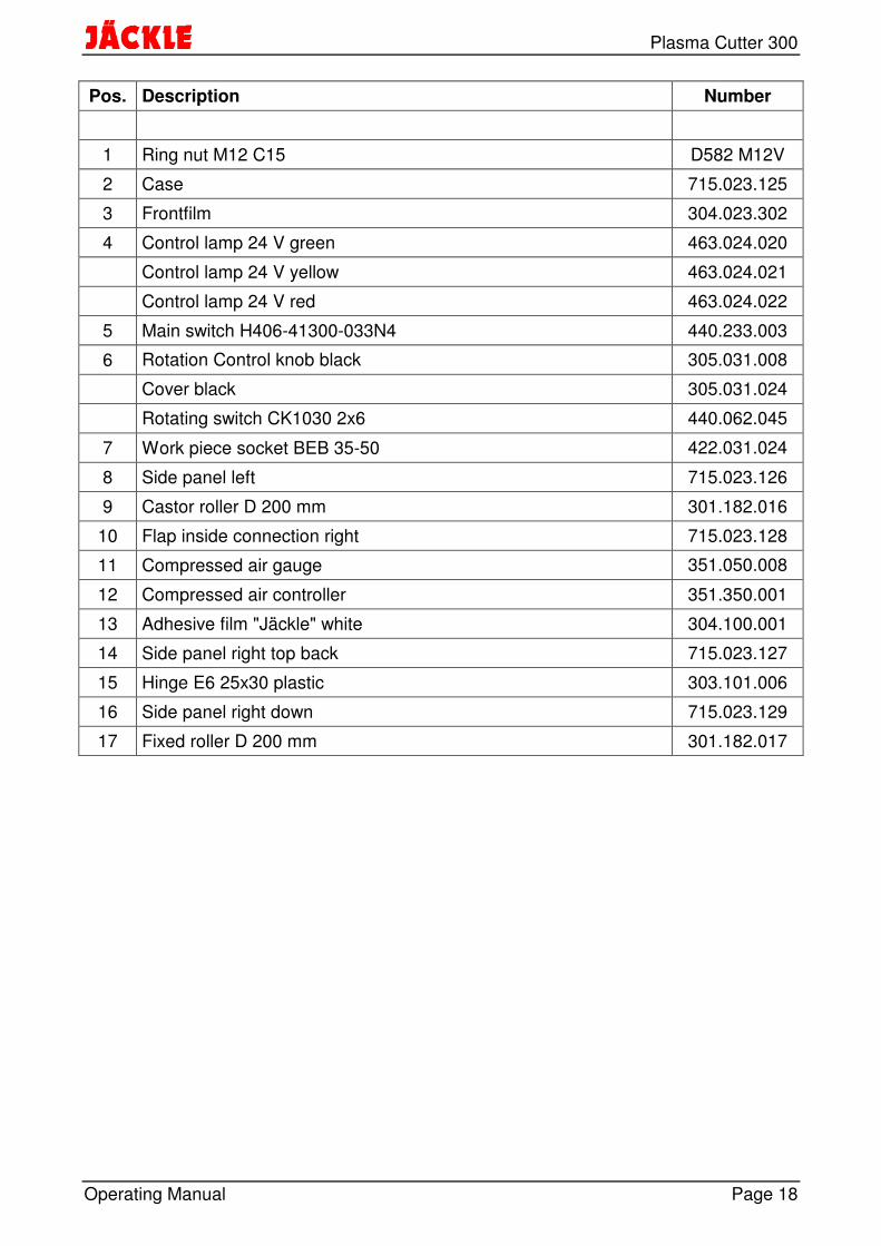
Picture 14.1 Frontview
Plasma Cutter 300
Operating Manual Page 18
Pos. Description Number
1 Ring nut M12 C15 D582 M12V
2 Case 715.023.125
3 Frontfilm 304.023.302
4 Control lamp 24 V green 463.024.020
Control lamp 24 V yellow 463.024.021
Control lamp 24 V red 463.024.022
5 Main switch H406-41300-033N4 440.233.003
6 Rotation Control knob black 305.031.008
Cover black 305.031.024
Rotating switch CK1030 2x6 440.062.045
7 Work piece socket BEB 35-50 422.031.024
8 Side panel left 715.023.126
9 Castor roller D 200 mm 301.182.016
10 Flap inside connection right 715.023.128
11 Compressed air gauge 351.050.008
12 Compressed air controller 351.350.001
13 Adhesive film "Jäckle" white 304.100.001
14 Side panel right top back 715.023.127
15 Hinge E6 25x30 plastic 303.101.006
16 Side panel right down 715.023.129
17 Fixed roller D 200 mm 301.182.017

Plasma Cutter 300
Operating Manual Page 19
Picture 14.2 Sideview

Plasma Cutter 300
Operating Manual Page 20
Pos. Description Number
20 Fuse holder with bayonet type sealing cap 464.601.001
fuse 6,3A slow 464.031.015
21 HF ignition unit SIG 3.2 24V 438.032.002
22 Flap security switch XP52 441.001.001
2-channel flat blade socket for torch trigger 410.002.020
23 Torch connection cpl. M6-1/4-M6 703.015.018
24 Torch connection cpl. G 3/8 703.017.009
25 Rapid action coupling DN5-G1/4I 355.014.007
Air connection G 1/4 357.141.003
26 HF blocking choke 1R100-25-14 438.100.019
27 cooler 309.361.002
30 Micro filter EAF 3000 G1/4 351.300.007
31 Safety bow Filter 715.023.117
32 Water pump stainless steel 456.220.011
33 Back protection 400mm 450.400.002
34 Protection grid 450.400.003
35 Fan400mm 450.400.001
36 Cutting transformer 300 706.023.200
40 Housing complete 715.023.100
41 Water tank 715.023.130
Tank screw cap DT 40 A.1 308.400.002
42 Resistor 5,4 Ohm 452.054.010
43 Strain relief screw fitting 29 420.029.007
Nut PG 29 420.029.008
44 Main cable 4x10mm2, 5m 63A plug 704.100.006
45 Case push-handle 715.023.120
46 Current transformer 438.077.006

Plasma Cutter 300
Operating Manual Page 21
Picture 14.3 Inside
Pos. Description Number
50 PCB WMP 1 600.100.030
51 Choke PLD 1 438.001.003
52 HF protection PCB P1-H 600.021.001
53 PCB AVZ 600.022.007
54 Auxiliary transformer 462.023.001
55 Big Contactor (Main) 442.024.018
56 Small Contactor DL 4K-10 24V/50Hz (Pilot) 442.024.011
57 Control pcb PL3 600.008.017
58 Fuse holder with bayonet type sealing cap 464.601.001
Fuse 6,3A slow 464.031.015
59 Reed switch 705.055.003
60 rectifier 12 Plate - 6 Diodes/ Plate 461.380.041
Plasma Cutter 300
Operating Manual Page 22
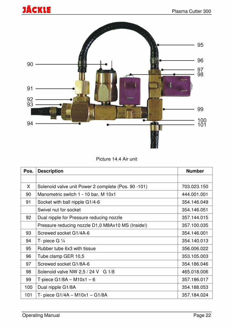
Picture 14.4 Air unit
Pos. Description Number
X Solenoid valve unit Power 2 complete (Pos. 90 -101) 703.023.150
90 Manometric switch 1 - 10 bar, M 10x1 444.001.001
91 Socket with ball nipple G1/4-6 354.146.049
Swivel nut for socket 354.146.051
92 Dual nipple for Pressure reducing nozzle 357.144.015
Pressure reducing nozzle D1,0 M8Ax10 MS (Inside!) 357.100.035
93 Screwed socket G1/4A-6 354.146.001
94 T- piece G ¼ 354.140.013
95 Rubber tube 6x3 with tissue 356.006.022
96 Tube clamp GER 10,5 353.105.003
97 Screwed socket G1/8A-6 354.186.046
98 Solenoid valve NW 2,5 / 24 V G 1/8 465.018.006
99 T-piece G1/8A – M10x1 – 6 357.186.017
100 Dual nipple G1/8A 354.188.053
101 T- piece G1/4A – M10x1 – G1/8A 357.184.024

Plasma Cutter 300
Operating Manual Page 23
15. Circuit diagram
JÄCKLE
24
6
13
5K
32
46
13
5K
4
~~
~
R3
R2C1
A3
Ho
24 V
A2
L1
+
M
M2
Was
serp
umpe
K1
.3-2
.4-2
K2
.1 .2
A 2,3
C 9
A1
A2
K3
A1
A2
K4
P S3
S6
S7
AV
Z87
45
A3
HF
Sch
utzp
latin
e P
1-H
L1
L2
S8
wor
kpie
ce
65
34
21
K2
R1
24
6
13
5K
1
T1F
1
T 6
,3 A
31
5
24
6
V1
Q1
P S5
Y1
Y2
A1
A2
K1
A1
A2
K2
L3
H1
H2
H3
T2
400
V
230
V
0 V
24 V 0 V
U
L1L2
L3P
E
S4
L3S
4
L3cu
rren
t tra
nsfo
rmer
mai
n sw
itch
Q1
M1
fan
R1
pilo
t res
isto
r5,
4 O
hm
A1
Na
me
:
Da
te:
Nr.
:
ciru
it di
agra
mP
lasm
a 30
0
400V
3~
50H
z
torc
h
M M2
S1
H1
cont
rol l
amp
mai
n
H3
cont
rol l
amp
erro
r
pilo
t con
tact
or
H2
K1,
3,4
K2
L1H
F c
hoke
mai
n co
ntac
tor
cont
rol l
amp
pilo
t
K1
.3-1
.4-1
Sch
we
iß-
und
Sch
neid
tech
nik
Sp
iele
r
03.0
2.09
T 1
A
41
1112
67
58
23
910
PL
3
L3
S4
A1
cont
rol p
cb
A2
igni
tion
unit
SIG
3.2
fuse
prim
ary
F1
PL
3
HB
L2ch
oke
PLD
1
F2
T4A
conn
ectio
nbo
x
Pilo
t
mai
n ca
ble
4G16
S2
S2
S2
S2
S2
S2
U1
V1
W1
U1
V1
W1
U1
V1
W1
U2
V2
W2
U2
V2
W2
U2
V2
W2
(cooler)
(middle)
(fan)
56 4 38 7 2 1
1 2 3 4 5A4
M1
Pot
i
S8
K2
.4-3
.3-3
S5
wat
er p
reas
sure
sw
itch
S6
cont
act c
onne
ctio
n fla
pS
7ro
tatio
n sw
itch1
00/2
00/3
00A
torc
htrig
ger
S1
air
prea
ssur
e sw
itch
S3
T1,
3,4
Cut
ting
tran
sfor
mer
s
rect
ifier
V1
Y2
sole
nois
val
ve c
uttin
g ai
r
ther
mos
witc
h Tr
afo
S2
S4
T2
Y1
sole
noid
val
ve lo
w a
ir
reed
con
tact
cut
ting
curr
ent
auxi
liary
tran
sfor
mer
S8
reed
- co
ntac
t WM
P p
cb
A4
WM
P-p
cb w
ater
/ fa
n co
ntro
l
S8
with
WM
P p
cb
PL3
00.0
02
T3
T4
Circuit diagram

Ihr Fachhändler / Your trader
Text und Abbildungen entsprechen dem technischen Stand bei Drucklegung. Irrtümer und Änderungen vorbehalten.Contents corresponding to technical standard at printing. Errors and subjects to change without notice excepted.05/09, online: www.jaeckle-sst.de, copyrightJÄCKLE GmbH Bad Waldsee, Germany
JÄCKLE Schweiß- u.Schneidtechnik GmbHRiedweg 4 u. 9D-88339 Bad WaldseeGERMANY