Embed Size (px)
DESCRIPTION
Operating manual, edition 6 of the Fendt Vario 900 with operating instructions and maintenance information
Citation preview
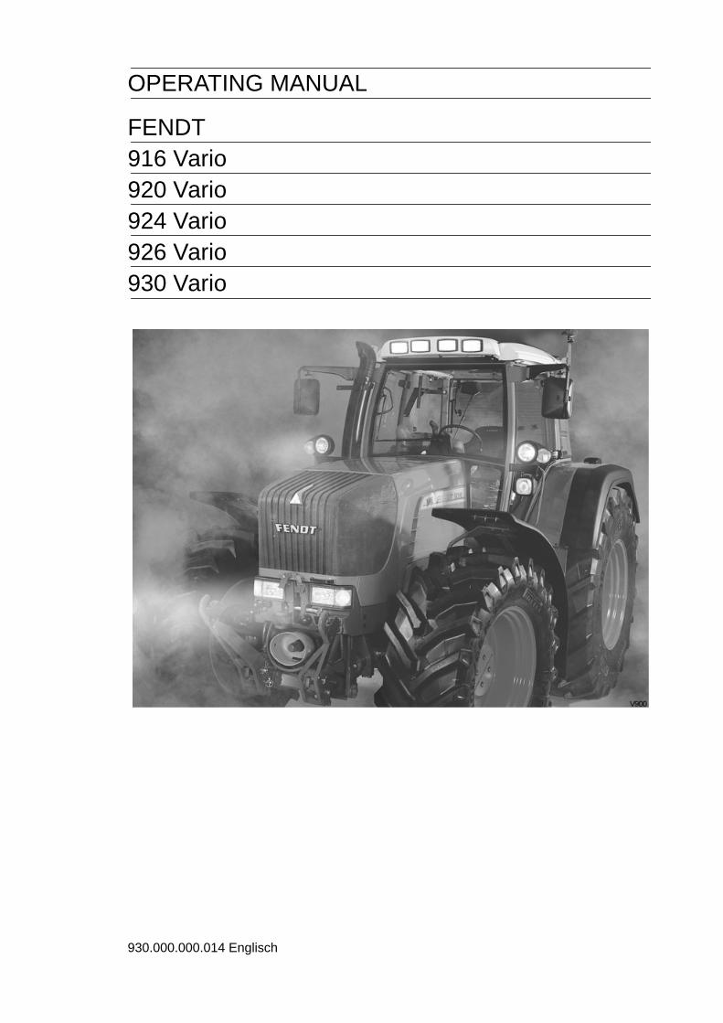
OPERATING MANUAL
FENDT916 Vario920 Vario924 Vario926 Vario930 Vario
930.000.000.014 Englisch

Vehicle delivery
Vehicle pre-delivery inspection by the Service WorkshopFor information, technical date etc. refer to Service Schedule.
Check oil level, top up if necessary.Engine, transmission, axle drives, front axle differential, hub drives, front PTO, lift shaftlubrication. Fill the hydraulic system with additional oil for external consumers as percustomer order.
Check fluid level, and top up if necessary.Cooling system, clutch operation, brake actuation, air conditioning if installed.
Grease vehicle as per Lubrication Chart, lubricate all joints.
Check steering and toe-in. Check tyre pressures. Check that wheel nuts are firmlyattached.
Test electrical system. Check fault memory. Check battery charge status. Check thefunction and settings of the lighting and signalling system.
Fill up with diesel, use pre-filter if necessary.
Check that brakes are working effectively.
Information to be given on vehicle deliveryDraw attention to safety instructions within the Operating Manual and on the vehicleitself.
Information on keeping to countryu-specific regulations regarding vehicle speed andtrailer braking systems.
Explain the following features in detail - see index - and show how they are operated.See also separate vehicle delivery test log.Operating controls, transmission, multiple display, initial start-up, starting, and switching off,fault display, code table, clearing the warning and fault messages.
Explain "Important Information on Service and Maintenance". See inside back cover.
Hand over tool box accessories.
Fill in warranty and delivery card and forward immediately to the factory.
For 50 km/h version, draw attention to the required regular vehicle inspections(country-specific).
Vehicle type .............................
Chassis No. ............................. After-Sales Service
Vehicle delivered on . . . . . . . . . . . . . . .
Signature of mechanic . . . . . . . . . . . . . . . . .

OPERATING MANUAL
FENDT 916 VarioFrom chassis number 916 .. 7001
FENDT 920 VarioFrom chassis number 920 .. 7001
FENDT 924 VarioFrom chassis number 924 .. 7001
FENDT 926 VarioFrom chassis number 926 .. 7001
FENDT 930 VarioFrom chassis number 930 .. 2001
ETManufacturerETAuthor
AGCO GmbHMaschinen und Schlepperfabrik D-87616 Marktoberdorf / Bavaria / GermanyTelephone +49 8342 77-0 Facsimile +49 8342 77-222
© PSD / Ko - SG 10.042941 F - en

4
Customer-notesText-module
Dear Customer,Please note the following:● Before using the tractor, carefully read
through this Manual to familiarize yourselfwith all operating controls and their functionsbefore you begin work. This also applies tothe operating instructions of the implementmanufacturer.
● Follow all the operating and maintenance in-structions. If you do so, your tractor will giveyou many years of economic and trouble-freeoperation. You will find an overview of allmaintenance operations in the Service Sche-dule in this Manual.
● Maintenance and repair work should be car-ried only at your service workshop. see alsothe "Important service and maintenance infor-mation".
Text-module
Authorised useThis tractor is designed only for normal agricultu-ral operations or similar purposes, for example inmunicipal applications.Any other type of use is considered unauthori-sed. The manufacturer will not be liable for anydamage resulting from such uses, which will beentirely at the owner's risk.Authorised use also means fulfilling the opera-ting, service and maintenance conditions set outby the manufacturer.Operation, maintenance and repair of the tractoris restricted to persons who are familiar with thiskind of work and aware of the inherent dangers.All relevant accident prevention regulations andall generally accepted health & safety standardsand road traffic regulations must be observedThe manufacturer does not accept liability for da-mage resulting from unauthorised modifications.Text-module
Marking of places that affect yoursafetyMake sure that any other users have read all thesafety instructions as well.The various levels of safety instructions can bedistinguished as follows:
Text-module
The Operating Manual is an integral part of thevehicle package and must be passed on to anysubsequent owner in the event of resale. The at-tention of the new owner should be drawn to thisinformation.If this Manual is lost or damaged and you need anew one, please contact your Fendt dealer,There you will be able to purchase a replace-ment.
Vehicle Identification NumberOperation_Pic_number:ETpicture-module
Text-module
The Vehicle Identification Number is on the rightframe and also stamped on the rating plate.Text-module
All specifications in the Manual are subject to theusual tolerances. We reserve the right to makedesign changes as part of technical further deve-lopment, without making alterations to this Ma-nual. The drawings and illustrations in the ma-nual are used for function description, some ofthe items shown are not necessarily included inthe vehicle delivery contents.
DANGER:Risk of serious accident.
WARNING:Risk of injury.
CAUTION:Possible risk of injury.

5
NUMERICAL INDEXSAFETY INSTRUCTIONS...............9
OPERATION....................................14
1. Driver seat ................................................141.1 Super deluxe seat ......................................14
2. Display instruments and operating controls.....................................................15
2.1 Front controls .............................................152.2 Glow and starter switch..............................162.3 Combination switch....................................162.4 Steering wheel adjustment.........................162.5 Quick reverse.............................................162.6 Dashboard .................................................172.7 Indication of fluid levels..............................182.8 Operating status display ............................182.9 Multiple display ..........................................192.10 Operating controls, right.............................192.11 Multi-function armrest ................................202.12 Operating console, right side .....................212.13 Vario terminal.............................................222.14 Camera function.........................................262.15 Quick Jump ................................................262.16 Cab top section, front.................................282.17 Cab top right side.......................................282.18 Power outlets .............................................292.19 Reset function ............................................31
3. Heating and ventilation ...........................313.1 Heater with 3-speed blower .......................313.2 Auxiliary ventilation in cab roof ..................323.3 Air conditioning ..........................................32
4. Rearwiew mirror.......................................33
5. Start-up .....................................................335.1 Daily check.................................................335.2 Cold weather operation..............................345.3 Tool box .....................................................34
6. Starting and stopping the engine...........346.1 Memory function ........................................346.2 Starting the engine.....................................356.3 Jump starting .............................................366.4 Tow-starting ...............................................376.5 Stopping the engine ...................................376.6 Stopping and immobilising the tractor........37
7. Vario transmission...................................377.1 Joystick ......................................................377.2 Neutral position ..........................................377.3 Selecting acceleration rates.......................387.4 Driving mode selector ................................397.5 Driving the tractor.......................................407.6 Changing direction of travel .......................427.7 Programmed changes of travel direction ...43
7.8 Cruise control.............................................447.9 Load limit control........................................467.10 Storing engine speeds ...............................477.11 Towing instructions ....................................48
8. Fuel consumption measurement............488.1 Activating fuel consumption
measurement.............................................48
9. Tractor Management System (TMS).......499.1 Engine management system .....................509.2 Accelerator mode.......................................509.3 Setting engine speed range .......................51
10. PTO............................................................5310.1 Rear PTO...................................................5310.2 Engaging and disengaging rear PTO.........5410.3 Front PTO ..................................................5510.4 Engaging and disengaging front PTO........5610.5 Calibrating rear and front PTO coupling ....56
11. Four wheel drive (4-WD)..........................58
12. Differential lock ........................................58
13. Front axle suspension.............................59
14. Power lift and PTO automatic mode ......6014.1 Power lift automatic mode..........................6014.2 PTO automatic mode .................................6114.3 PTO automatic mode with power lift ..........62
15. Brakes .......................................................6315.1 Foot brake..................................................6315.2 Hand brake ................................................6315.3 Trailer brake...............................................6415.4 Engine brake..............................................64
16. Steering.....................................................6516.1 Steering wheel adjustment.........................65
17. Hydraulics.................................................6517.1 General notes on hydraulic operations ......6517.2 Valve locking..............................................6617.3 Valve equipment ........................................6717.4 Operating the valves ..................................6717.5 Priority function ..........................................6917.6 Setting the valves.......................................7017.7 External valve actuation.............................7317.8 Hydraulic connectors .................................74
18. Electronic lifting gear control, rear ........7518.1 Controls......................................................7518.2 EPC safety lock..........................................7618.3 Control panel functions ..............................7718.4 Working with the EPC................................7918.5 Electronic slip control .................................8118.6 Electro-hydraulic external control...............83
6
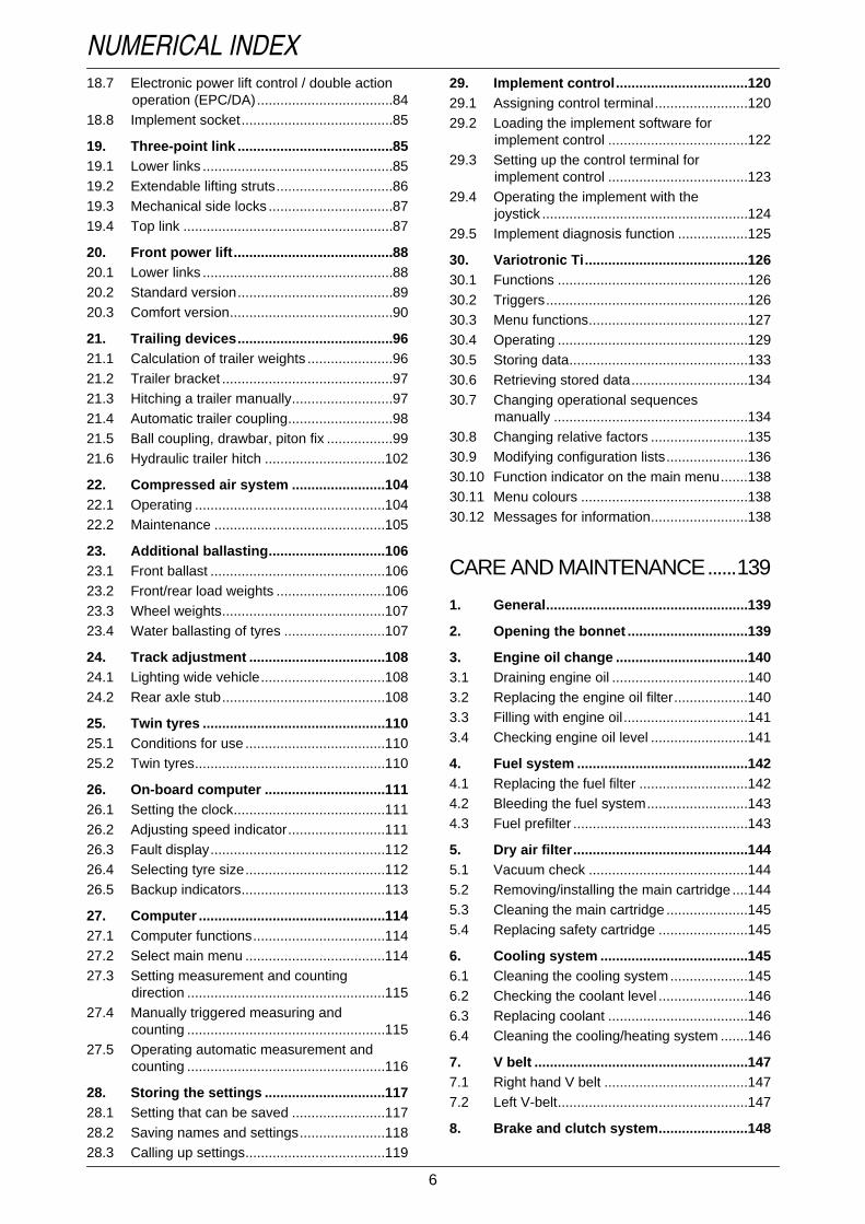
NUMERICAL INDEX18.7 Electronic power lift control / double action
operation (EPC/DA)...................................8418.8 Implement socket.......................................85
19. Three-point link ........................................8519.1 Lower links .................................................8519.2 Extendable lifting struts..............................8619.3 Mechanical side locks ................................8719.4 Top link ......................................................87
20. Front power lift.........................................8820.1 Lower links .................................................8820.2 Standard version........................................8920.3 Comfort version..........................................90
21. Trailing devices........................................9621.1 Calculation of trailer weights ......................9621.2 Trailer bracket ............................................9721.3 Hitching a trailer manually..........................9721.4 Automatic trailer coupling...........................9821.5 Ball coupling, drawbar, piton fix .................9921.6 Hydraulic trailer hitch ...............................102
22. Compressed air system ........................10422.1 Operating .................................................10422.2 Maintenance ............................................105
23. Additional ballasting..............................10623.1 Front ballast .............................................10623.2 Front/rear load weights ............................10623.3 Wheel weights..........................................10723.4 Water ballasting of tyres ..........................107
24. Track adjustment ...................................10824.1 Lighting wide vehicle................................10824.2 Rear axle stub..........................................108
25. Twin tyres ...............................................11025.1 Conditions for use ....................................11025.2 Twin tyres.................................................110
26. On-board computer ...............................11126.1 Setting the clock.......................................11126.2 Adjusting speed indicator.........................11126.3 Fault display.............................................11226.4 Selecting tyre size....................................11226.5 Backup indicators.....................................113
27. Computer ................................................11427.1 Computer functions..................................11427.2 Select main menu ....................................11427.3 Setting measurement and counting
direction ...................................................11527.4 Manually triggered measuring and
counting ...................................................11527.5 Operating automatic measurement and
counting ...................................................116
28. Storing the settings ...............................11728.1 Setting that can be saved ........................11728.2 Saving names and settings......................11828.3 Calling up settings....................................119
29. Implement control..................................12029.1 Assigning control terminal........................12029.2 Loading the implement software for
implement control ....................................12229.3 Setting up the control terminal for
implement control ....................................12329.4 Operating the implement with the
joystick .....................................................12429.5 Implement diagnosis function ..................125
30. Variotronic Ti..........................................12630.1 Functions .................................................12630.2 Triggers....................................................12630.3 Menu functions.........................................12730.4 Operating .................................................12930.5 Storing data..............................................13330.6 Retrieving stored data..............................13430.7 Changing operational sequences
manually ..................................................13430.8 Changing relative factors .........................13530.9 Modifying configuration lists.....................13630.10 Function indicator on the main menu.......13830.11 Menu colours ...........................................13830.12 Messages for information.........................138
CARE AND MAINTENANCE......139
1. General....................................................139
2. Opening the bonnet ...............................139
3. Engine oil change ..................................1403.1 Draining engine oil ...................................1403.2 Replacing the engine oil filter...................1403.3 Filling with engine oil................................1413.4 Checking engine oil level .........................141
4. Fuel system ............................................1424.1 Replacing the fuel filter ............................1424.2 Bleeding the fuel system..........................1434.3 Fuel prefilter .............................................143
5. Dry air filter.............................................1445.1 Vacuum check .........................................1445.2 Removing/installing the main cartridge ....1445.3 Cleaning the main cartridge .....................1455.4 Replacing safety cartridge .......................145
6. Cooling system ......................................1456.1 Cleaning the cooling system....................1456.2 Checking the coolant level .......................1466.3 Replacing coolant ....................................1466.4 Cleaning the cooling/heating system .......146
7. V belt .......................................................1477.1 Right hand V belt .....................................1477.2 Left V-belt.................................................147
8. Brake and clutch system.......................148
7
NUMERICAL INDEX9. Front PTO ...............................................149
10. Transmission and axle drives...............14910.1 Changing the transmission oil..................14910.2 Checking the transmission oil level..........15010.3 Changing the oil in the axle drives ...........151
11. Four-wheel drive axle ............................15111.1 Changing the oil in the front axle
differential gear ........................................15111.2 Replacing the oil in front axle hub drives .15211.3 Front axle suspension..............................152
12. Power lift.................................................153
13. Hydraulic system ...................................15313.1 Checking oil level in hyrdraulic system ....15313.2 Changing the hydraulic oil........................15413.3 Hydraulic oil filter......................................154
14. Steering...................................................156
15. Front wheels...........................................15615.1 Checking toe-in ........................................156
16. Heating and ventilation .........................15716.1 Removing the heater fan filter..................15716.2 Replacing the roof fan filter ......................15716.3 Replacing the recirculating air filter..........158
17. Air conditioning .....................................15817.1 Condenser ...............................................15817.2 Compressor V-belt ...................................159
18. Windshield washer system...................159
19. Cleaning the tractor ...............................15919.1 Clean the cab's air spring bellows............159
20. Electrical and electronic systems ........16020.1 Battery......................................................16020.2 Alternator .................................................16020.3 Electrowelding..........................................16020.4 Adjusting the headlights...........................16020.5 Adjusting the auxiliary headlampss..........16120.6 Auxiliary lights, Xenon headlights ............16120.7 Additional installation of electrical and
electronic equipment................................162
21. Fuses.......................................................16321.1 Fuse holder X050.....................................16421.2 Fuse holder X051.....................................16521.3 Fuse holder F060 - F067 .........................16621.4 Fuse holder (A013) ..................................167
22. Wiring diagrams.....................................16822.1 Legend for circuit diagrams......................16822.2 Colour coding for electric wires................17122.3 Wiring diagrams .......................................171
IMPLEMENTS...............................204
1. Reversing device ...................................204
FAULTS AND REMEDIALACTIONS........................................205
1. Warning and fault messages ................2051.1 Warning messages ..................................2051.2 Fault messages........................................2111.3 Clearing a warning or fault message .......2151.4 General faults...........................................216
2. Variotronic Ti fault messages...............223
3. Warning and information messages for implement settings ..........................227
4. Flame starting system faults ................228
5. Fault code tables....................................229
6. Emergency operation ............................245
TECHNICAL DATA.......................247
1. Technical data ........................................247
2. Tyre pressures .......................................251
3. Tyre combinations .................................252
4. Fuel and lubricants Vario 916 - 930......2534.1 Bio-diesel .................................................2544.2 Bio hydraulic oil........................................254
5. Lubrication chart....................................2555.1 Filling points .............................................2555.2 Lubrication points.....................................256

8
NUMERICAL INDEX

9
SAFETY INSTRUCTIONS
Safety and accident prevention regulations
Safety signs on the machine must be replaced if damaged or lost.
WARNING:Before every operation, check the tractor for road worthiness and operational safety.Carefully read the Manual and observe all safety instructions.
General safety and accidentprevention regulationsText-module
ETNum-list
Carrying passengersText-module
ETNum-list
1.Follow the general safety and accidentprevention regulations, as well as the safetyinformation in this manual.
2.When driving on public roads, follow the usualtraffic regulations!
3.Before starting work, familiarise yourself withall operating controls and their functions. Don'twait until after you have started working!
4.Start the engine from the driver seat only. Donot attempt to start by shorting across thestarter terminals, as this can cause the tractorto move immediately!
5.Before starting up, check the area is clear (e.g.children). Ensure that nothing obstructs vision.
6.Never leave the engine running in a confinedspace!
7.The driver should wear close-fitting clothing.Avoid wearing loose-fitting garments!
8.Take extra care when handling fuel - seriousfire hazard. Never re-fuel in the presence ofsparks or naked flames. Do not smoke whenre-fuelling.
9.Before re-fuelling, turn off the engine andremove the ignition key. Do not re-fuel inconfined spaces. Clean up spillagesimmediately!
10.To avoid fire hazard, keep the tractor clean.11.Beware of leaking brake fluid and battery
acid (these are toxic and corrosive).
1.Passenger should be carried only if the tractoris fitted with an appropriate passenger seat.
2.Do not carry passengers in any other othercircumstances.
Driving the tractorText-module
ETNum-list
Front loader operationText-module
1.Driving speed must always be adapted to thecurrent situation. Avoid sudden corneringwhen driving uphill or downhill, or acrossgradients. Disengage the differential lockwhen cornering. Never disengage the clutch toshift gears when travelling downhill!
2.Make sure all trailers and implements areproperly hitched. Driving characteristics,steering and braking are affected by mountedimplements, trailers and ballast weight.Therefore, always ensure that there isadequate steering and braking capacity.
3.Observe the maximum permissible grossvehicle weight, axle loads and tyre loadcapacity, especially if heavy implements areattached.
4.When negotiating bends with implementsconnected or hitched up, always allow for theoverhang and oscillating weight of theimplement.
1.Never allow anyone to stand in the hazardarea, or within the working range of the frontloader. Keep the area clear of bystanders at alltimes. Do not operate the front loader unlessthere is a clear view of the entire working area- illuminate the area if necessary.
2. It is not permitted to use the standard loader(as supplied) as a working platform. If usingthe loader with a special working platform,additional safety measures are required.
3.Do not handle round bales, pallets etc. unlessthe loader is suitably equipped for thispurpose. If loading objects that cannot besecured and may fall off, do not use the frontloader unless the driving seat is protected by arobust canopy.
10
SAFETY INSTRUCTIONS
ETNum-list
4.When the front loader is raised, the risk of thetractor tipping over is greater, and the brakingeffect at the rear axle may also be reduced.Adapt your driving style and ensure adequateballasting at the rear. For additional loading,we recommend attaching the Fendt 870 kgadditional weight at the three-point link - fitwheel weights and fill the tyres if necessary.
5.Keep a safe distance from high-voltagecables.
6.When on public roads, bring the front loaderinto the transport position and secure it. Keepa maximum distance of 3.5 m between theimplement and the centre of the steeringwheel. If the forward projection exceeds 3.5 m,appropriate measures must be taken toguarantee safe traffic conditions (e.g. usepeople on foot acting as guides or mirrors atroad junctions). Transporting equipment ormaterials with a front loader workingimplement, e.g. a scoop, is not permitted whentravelling on public roads.
7.Danger from unintended lowering of the frontloader. Always secure hydraulic lever at theend of operation. Before leaving the tractor,completely lower the front loader to theground.
8.For safety reasons the front loader should bemounted and removed by one person only, thedriver himself.
9.Always keep hands away from the crushingand cutting areas while parts may still bemoving.
10.Detach the front loader with the attachedimplement (bucket, fork) only on firm andlevel ground. Always use the supportsprovided.
11.The front loader must be parked and securedin such a way as to prevent unauthorisedpersons or children from causing it to tip over.
12.When mounting the front loader, connect allhydraulic connections including the auxiliaryreturn, if equipped in this way. Alwaysconnect hydraulic hose for cylinder loadpressure to +. Take great care not to confuseconnections since this may cause accidentsthrough reversed functions, e.g. liftinginstead of lowering. Before fitting the multiplecoupler, remove the load from hydraulichoses and unplug rear hydraulicconnections, lower the power lift and operateonly via EPC. Hydraulic fluid interflow cancreate danger from unintentional equipmentmotion.
Leaving the tractorText-module
ETNum-list
Mounted and trailing equipmentText-module
ETNum-list
PTO operationText-module
ETNum-list
1.Make sure the tractor is properly securedagainst running off (parking brake, wheelchocks). Switch off the engine and apply thehand brake!
2.Remove the ignition key and lock the cab ifnecessary.
3.Never leave the tractor unattended while theengine is running.
4.Never leave the cab while the tractor is inmotion.
5.Completely lower the mounted implementbefore leaving the tractor.
1.Only attach implements and trailers using theprescribed devices.
2.Use only trailers which comply with thecountry-specific regulations. Do not exceedmaximum vertical bearing load. Ensure thatthe tractor-trailer brake system is functioningcorrectly.
3.Take special care when hitching trailers orimplements!
4.Secure trailers and implements to preventthem rolling. Make sure that detachedimplements and components are safelyparked.
5.Be sure all protection devices are correctlyattached and in the safety position beforeoperating the tractor.
6.When using the power lift, always remain welloutside the travel range of the three-point linkattachment!
1.Always switch off the engine, before fitting orremoving the drive shaft. The PTO shaft mustbe in 0-position.
2.During PTO operations, allow no-one in thevicinity of the rotating PTO or drive shaft.
3.Make sure drive shaft and PTO are equippedwith protective guards and sleeves.
4.After switching off the PTO, the attachedimplement may continue running due to theflywheel mass. In this case, do not go near theimplement. Approach it only when it has cometo a complete standstill.
5.When the drive shaft is removed, cover thePTO shaft with its protective cap.

11
SAFETY INSTRUCTIONSMaintenanceText-module
ETNum-list
1.Before maintenance and repair work, switchoff the engine and remove the ignition key.Relieve pressure from implement lines, e.g. tothe front loader.
2.Any person should keep clear of a lifted,unsecured load (e.g. tilted cab and similar).
3.Never open or remove any protection deviceswhile the engine is running.
4.Never grasp leaking pressure lines.Pressurised fluids (diesel or hydr. oil) escapingunder high pressure can penetrate the skinand cause severe injuries. If this has occurred,seek medical advice at once to avoid the riskof serious infection.
5.Keep at a safe distance from hot areas.6.Hydraulic accumulator and connected pipes
are highly pressurised. Only remove andrepair in accordance with instructions providedin Technical Manual.
7.To avoid eye injury, do not look directly at thesurface of the activated radar sensor.
8.Dispose of oil, fuels and filters properly!9.For fitting tires, specialist knowledge and
special mounting tools are required.10.Run the tractor for a short time, then
retighten all wheel nuts and bolts; checkthem regularly. For correct torque valuesrefer to TECHNICAL DATA.
11.Before working on the electrical system,always remove the ground strap from thebattery. Observe the following, when carryingout electric welding. When carrying outelectric welding on tractor or mountedimplements, make sure that both batteryterminals are disconnected. Attach theground terminal as close as possible to thewelding point.
12.Spare parts must at least meet the technicalrequirements stated by the manufacturer.You can ensure that this is the case by usinggenuine spare parts!
Text-module
ETNum-list
Advice for front loader maintenance:1.Before undertaking maintenance work, lower
the front loader to the ground, switch off theengine and remove the ignition key.
2. If the pipe fracture protection has engaged,support the load before starting repairs, andslowly retract the cylinder.
3.Hydraulic hoses deteriorate with age. Checkthe condition of hydraulic hoses at regularintervals, and replace them in good time.
4.After attachment and repair operations, drivethe tractor for a short time then retighten allmounting screws and nuts and check themregularly.
5.Retighten eccentric bolt for front loaderattachment, if necessary.

12
SAFETY INSTRUCTIONSLocation of safety signs
Operation_Pic_number:1
Inside the cab on the right.Operation_Pic_number:1
Inside the cab on the right.Operation_Pic_number:1
On the right rear mudguard.
Fig.1
Fig.2
Fig.3
Operation_Pic_number:1
On the left and right rear mudguards beside thelifting gear control.
Operation_Pic_number:1
At left front of hydraulic cylinder of front axlesuspension.
Operation_Pic_number:1
On pressure reservoir of front axle suspension.
Fig.4
Fig.5
Fig.6

13
SAFETY INSTRUCTIONSOperation_Pic_number:1
Inside the cab on left.Operation_Pic_number:1
Inside the cab, on the cover of the emergencyoperation controls.
Operation_Pic_number:1
On the front loader forks, left and right.Operation_Pic_number:1
Inside the cab, on the left, on the transversebeam of the front windscreen.
Fig.7
Fig.8
Fig.9
Fig.10

14
OPERATION
1. Driver seat
WARNING:Never adjust the seat while the tractor is moving (risk of accident).If a seat belt is available, always attach it.
1.1 Super deluxe seatOperation_Pic_number:1
Text-module
A = Automatic weight and height adjust-ment.
B = Swivel mechanism.C = Longitudinal adjustment.D = Backrest adjustment.E = Lumbar support (curvature), pneumatic
operation.F = Seat bolster (depth adjustment).G = Seat bolster (tilt adjustment).H = Horizontal springing (on/off).I = Vertical springing (adjustable from soft to
hard in four levels).J = Backrest extension.K = Behind the moulding:
Seat belt fixing point.L = Seat heating.
Fig.1

15
OPERATION
2. Display instruments and operating controls
2.1 Front controlsOperation_Pic_number:1
Text-module
A = Hand brakeB = Clutch pedalC = Steering wheel adjustment and quick reverse.D = Heater and fan controls (see also OPERATION Section 3).E = Combination switchF = Heater starter switchG = Multi-function armrestH = Accelerator pedalI = Brake pedalsK = Emergency operation controls (under the cover).L = Hand throttle
Fig.2

16
OPERATION2.2 Glow and starter switch
Operation_Pic_number:1
Text-module
0 = Ignition off, key can be removed.I = General ignition, key cannot be removed
+ preheating (automatic).II = Starting + ignition.
2.3 Combination switchOperation_Pic_number:1
Text-module
A = Right indicator.B = Left indicator.C = 1. With lights switched on: toggle low
beam, high beam.2. With lights switched off headlight flas-her.
D = HornE = Windshield washer system (wipers run
automatically).F = Windshield wipers with intermittent and
continuous operation.
Fig.3
Fig.4
2.4 Steering wheel adjustment
Operation_Pic_number:1
Text-module
● Pull up lever and adjust steering wheel to thedesired position (see also OPERATION Sec-tion 16).
2.5 Quick reverseOperation_Pic_number:1
● Press button (A).
The tractor slows to a standstill, then acceleratesin the opposite direction up to previous transmis-sion ratio (see also OPERATION Section 7.6).
WARNING:Never adjust the steering wheelwhile the tractor is moving!
Fig.5
Fig.6

17
OPERATION
2.6 DashboardOperation_Pic_number:1
Text-module
Fig.7
A = Multiple displayB = Indication of fluid levelsC = Operating status displayD = Indicator lampsE = Lights including side lightsF = Hazard warning flasher switchG = Key pad for on-board computer (also
see OPERATION Section 26).
H = Key pad for rpm indicators (also seeOPERATION Section 2.8).
J = Key pad for speed display (also seeOPERATION Section 2.8).
K = Emergency mode (also see FAULTSAND REMEDIAL ACTIONS Section 6).
L = Alternator 1 not charging, red.M = Hydraulic trailer brake (optional), (see
also OPERATION Section 15.3).
Text-module
Left turn signal indicator, green.
Preheater indicator lamp, red.
Alternator 2 not charging, red.
High beam, blue.
1st trailer light indicator, green.
2nd trailer light indicator, green.
Hazard light, red.
Forward direction of travel, green.
Reverse direction of travel, green.
4-WD engaged, green.
Differential lock engaged, red.
Text-module
Automatic dimmerfor forward/reverse indicator lamps, 4-WD, diffe-rential lock and related buttons.At dusk or in the dark, the dimmer can be adju-sted manually.
Cruise control on.
Right turn signal indicator, green.
If one of the indicator lamps for forward/reversefails, back-up indicators can be activated on themultiple display (A) activation (see seeOPERATION Section 26.5).
Brightness is increased or decreased bypressing one of the two buttons.

18
OPERATION2.7 Indication of fluid levels
Operation_Pic_number:1
Text-module
A = Fuel supplyB = Engine temperature
When the bar indicators reach the redzone, relieve the engine of load imme-diately and allow to cool down for about2 minutes at 1000 rpm, then turn the en-gine off.
C = Compressed air supplyD = On-board electrical system voltageE = Hydraulic oil supply
Fig.8
2.8 Operating status displayOperation_Pic_number:1
Text-module
A = Wheel slip in %;(only if optional radar sensor is equip-ped).
B = Tractor speed in km/h.Text-module
On tractors with the optional radar sensor, usethese keys to change to:
NOTE:For a precise reading, adjust the speed indi-cator under operating conditions (see alsoOPERATION Section 26.2).Text-module
D = Driving mode indicatorthe selected driving mode is indicated bya spot (D).
E = Rpm indicatorcan be changed with the buttons to:
Text-module
theoretical speed measurementcalculated from transmission speed.
actual speed based on signal from radarsensor, symbol (C) is lit.
Theoretical speed calculation is activated auto-matically when tractor speed is over15 km/h, the wheel slip indicator (A) and symbol(C) then go out.
engine speed symbol (H) is displayed.
rear PTO speed symbol (F) is displayed.
front PTO speed symbol (G) is displayed.
Fig.9

19
OPERATION2.9 Multiple displayFor warnings, fault messages and on-boardcomputer functions.
Operation_Pic_number:1
In the basic display, the clock (A) and operatinghours (B) are indicated. This is interrupted forwarnings, fault messages and on-boardcomputer functions.
Fig.10
2.10 Operating controls, rightOperation_Pic_number:1
Text-module
A = Hand throttleB = Behind the moulding, M10 threaded ho-
les for fixing additional equipment, e.g.radio or telephone, (see also CARE ANDMAINTENANCE Section 20.7).
C = FusesD = Document boxE = Control terminal
Fig.11

20
OPERATION2.11 Multi-function armrest
Operation_Pic_number:1
Text-module
A = Joystick (see also OPERATION Section 7.1).B = Acceleration rate selection (see also OPERATION Section 7.3).C = Activating button on the back of the joystick.D = EPC PTO automatic mode stop button (see also OPERATION Section 14.2).E = Floating position of hydraulic valve, green or blue (see also OPERATION Section 17.3).F = Lifting/lowering hydraulic valve, green or blue (see also OPERATION Section 17.3).G = Floating position of hydraulic valve red or yellow (see also OPERATION Section 17.3).H = Lifting/lowering of hydraulic valve red or yellow (see also OPERATION Section 17.3).I = Rear power lift/ PTO automatic mode (see also OPERATION Section 14.2).J = Front power lift/ PTO automatic mode (see also OPERATION Section 14.2).K = 3rd hydraulic circuit on front loader.L = Crossgate lever, lifting/lowering and floating position of hydraulic valves, yellow/blue or red/
green (see also OPERATION Section 17.3).M = Driving mode selector (see also OPERATION Section 7.4).N = Neutral button with neutral selected LED (see also OPERATION Section 7.2).O = Accelerator pedal function (see also OPERATION Section 9.2).P = Electronic engine control (also refer to OPERATION Section 9).R = Accelerator pedal release (see also OPERATION Section 9.2).
Fig.12
21
OPERATION
2.12 Operating console, right sideOperation_Pic_number:1
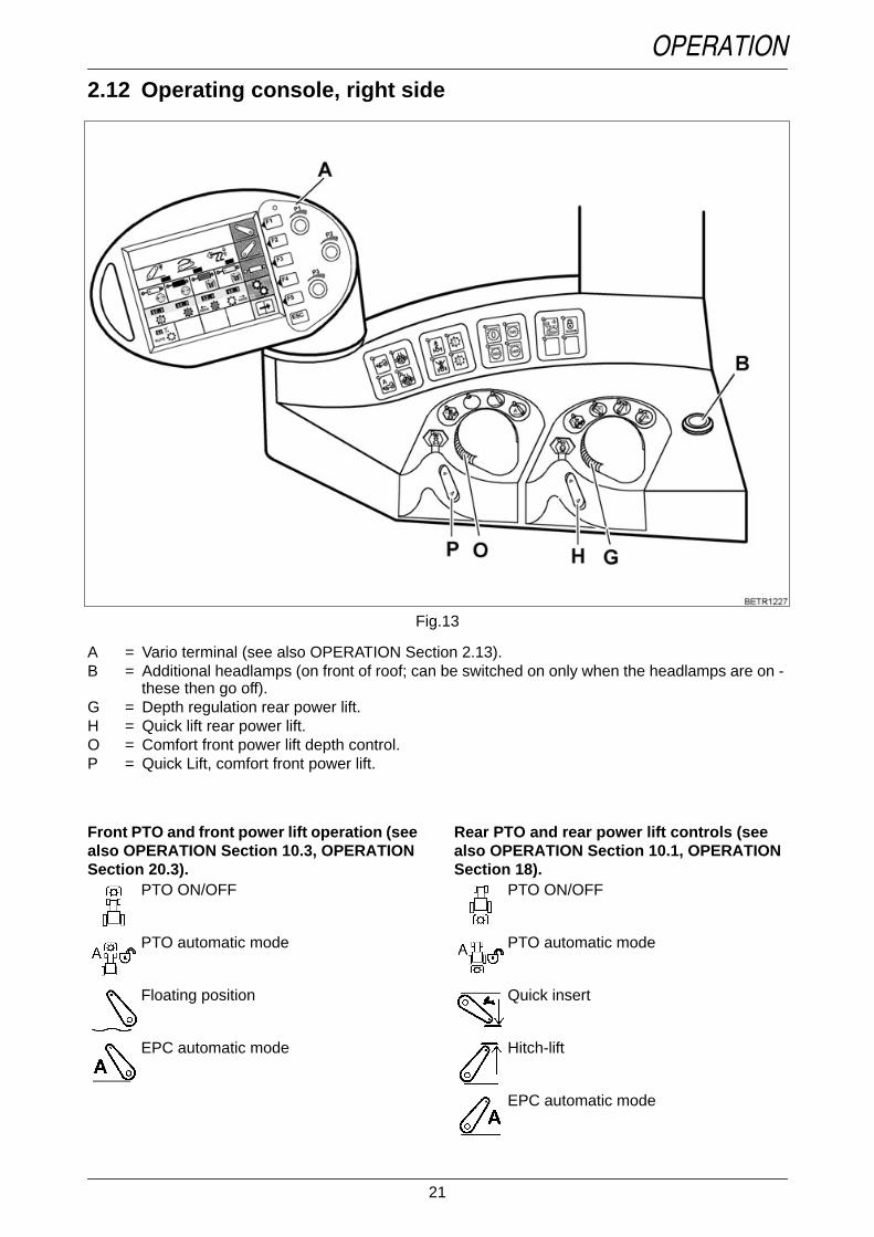
Text-module
A = Vario terminal (see also OPERATION Section 2.13).B = Additional headlamps (on front of roof; can be switched on only when the headlamps are on -
these then go off).G = Depth regulation rear power lift.H = Quick lift rear power lift.O = Comfort front power lift depth control.P = Quick Lift, comfort front power lift.
Fig.13
Text-module
Front PTO and front power lift operation (seealso OPERATION Section 10.3, OPERATIONSection 20.3).
PTO ON/OFF
PTO automatic mode
Floating position
EPC automatic mode
Text-module
Rear PTO and rear power lift controls (seealso OPERATION Section 10.1, OPERATIONSection 18).
PTO ON/OFF
PTO automatic mode
Quick insert
Hitch-lift
EPC automatic mode

22
OPERATIONText-module
Text-module
Text-module
Text-module
Text-module
Text-module
4-WD (see also OPERATION Section 11).4-WD 100%; ON/OFF
4-WD automatic mode ON/OFF
Differential lock (see also OPERATIONSection 12).
Differential lock 100 % ON/OFF
Differential lock automatic mode ON/OFF
Front axle suspension (also see OPERATIONSection 13).
Suspension locked
Suspension ON
Tempomat cruise control (see also OPERATI-ON Section 7.8).
Memory 1
Memorised speed 2
Hydraulic valves (see also OPERATIONSection 17.3).
Hydraulic valve controlThe operating functions of the crossgatelever and the controls on the joystick areinterchanged.Locking the hydraulic valves
Speed preselection for rear PTO (see alsoOPERATION Section 10.1).
PTO neutral
PTO 540
Economy PTO (750)
PTO 1000
2.13 Vario terminalOperation_Pic_number:1
Text-module
NOTE:At low temperatures, a red-orange discolou-ration along with a decrease in contrast anddelayed display may occur for up to 20 minu-tes.At high temperatures there may be a loss ofcontrast.
Text-module
After the start-up display, the following first mainmenu is displayed.
Fig.14

23
OPERATIONFirst main menu
Operation_Pic_number:1
Text-module
Pressing keys (F1 - F5) gives access to the following functions.F1 = Comfort front power liftF2 = Rear EPCF3 = Electric valvesF4 = Transmission settingsF5 = Switch to 2nd main menu level
Display of prevailing operating status of:
A = Rear EPCB = Electric valvesC = Cruise controlD = Programmed changes in direction of travelE = Load limit controlF = Prioritised valveG = Active on-board computerH = LBS-ISO function (optional)I = Front power lift - floating positionK = Variotronic Ti - function displayL = Tractor Management SystemM = Hydraulic valve heatingN = Stored engine speed activatedO = Accelerator rangeP = Accelerator pedal drive activeR = Measuring fuel consumptionS = Slip control active (optional)T = Front EPC activeU = Rear EPC activeV = External valve actuationW = Rear power lift - floating position
Fig.15

24
OPERATIONSecond main menu
Operation_Pic_number:1
Text-module
Pressing keys (F1 - F5) gives access to the follo-wing functions.F1 = On-board computerF2 = Store terminal settingsF3 = Implement controlF4 = Variotronic TiF5 = Switch to third menu
Press the ESC key● Display returns to first main menu.
Fig.16
Third main menuOperation_Pic_number:1
Text-module
Pressing keys (F1 - F5) gives access to the follo-wing functions.F1 = Camera image (optional).F2 = Camera image mirrored (optional).F3 = Quick JumpF4 = Terminal settingsF5 = Switch to first main menuText-module
Settings can be made with the 3 rotary controls(P1, P2, P3) ora preset menu page (Quick Jump) can be selec-ted.Text-module
Press the ESC key● Display returns to first main menu.
The right rotary control for thesettings is displayed in the Varioterminal.
Fig.17

25
OPERATIONAdjusting screen brightness andcontrastThe brightness of the Vario terminal isautomatically adjusted.
Dimming can be adjusted steplesssly ifnecessary.
Operation_Pic_number:1
Text-module
It is set in the third main menu● Press key F4.
Following sub-menu for terminal settings appe-ars.
Fig.18
Operation_Pic_number:1
● Rotary control (P1) for setting degree of dim-ming.
Bar indicators:
right = no dimming.left = max. dimming.
Any setting between the two positions is possi-ble.
Text-module
Pressing keys (F1 - F5) gives access to the follo-wing functions.F1 = No function.F2 = Service function (LBS-ISO) for the work-
shop.F3 = Service function for the workshop.F4 = No function.F5 = LBS-ISO (optional).
Press ESC key● Display returns to first main menu.
Fig.19

26
OPERATION2.14 Camera functionText-module
(optional).Operation_Pic_number:1
● Press the F1 or F2 key.
Following sub-menu for terminal settings appe-ars.
Operation_Pic_number:1
Text-module
Press the ESC key twice.● Toggles between main, implement and ca-
mera menus.
Setting brightness and contrast.● Brightness can be set with the rotary control
(P1).● Contrast can be set with the rotary control
(P2).
Fig.20
Fig.21
2.15 Quick JumpText-module
This function allows a preset menu page to beselected directly from the first menu level.Turning the rotary control (P1 - P3) slightly, se-lects the preset menu page.
Press ESC key● Display returns to first main menu.
Selecting menu pagesOperation_Pic_number:1
● Press F3 key.
Following sub-menu for terminal settings appe-ars.
Operation_Pic_number:1
● Choose the desired menu page with the F2 -F4 keys.
Press key repeatedly until the desired menupage appears.
● Switch function on and off with the F5 key.● LED lights up green - function is on.Text-module
Fig.22
Fig.23

27
OPERATIONSelection of the jump menu itemsThe jump menu items that can be selected, de-pend on the tractor equipment, e.g. if no frontpower lift is fitted, this jump menu item is notshown in the selection list.
Front power lift
Rear power lift
Rear power lift settings
Rear power lift settings, slip control
Overview of electrical valves
Electrical valves 1-4
Cruise control, load limit control
Quick reverse
Engine speed min. - max.
Fuel consumption indicator
On-board computer overview
On-board computer 1- 4
Load implement settingsOnly possible if Teach In and theautomatic modes for the power lift andPTO are not active.
Save implement settingsOnly possible if Teach In and theautomatic modes for the power lift andPTO are not active.
Implement controlOnly possible if implement beinginstalled.
Teach-in
Camera
Camera image mirrored
Terminal settings
Implement control diagnostics
Tractor diagnostics 1
Tractor diagnostics 2
TMS settings
Page with speeds
28
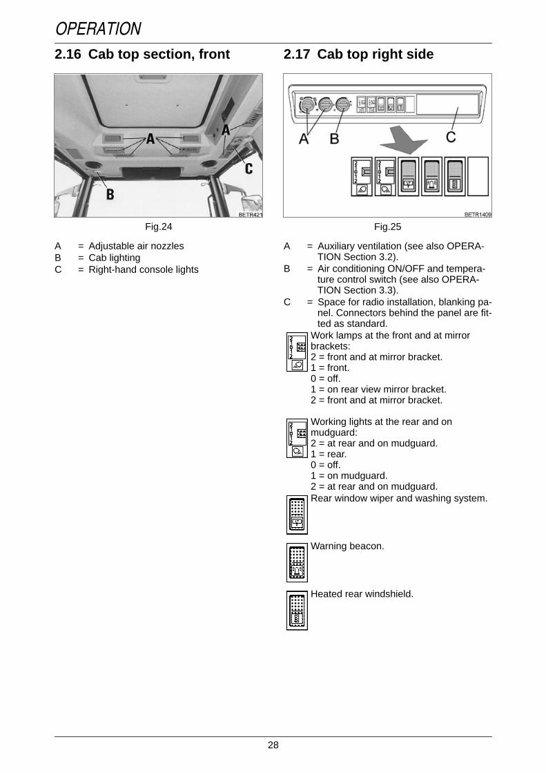
OPERATION2.16 Cab top section, front
Operation_Pic_number:1
Text-module
A = Adjustable air nozzlesB = Cab lightingC = Right-hand console lights
Fig.24
2.17 Cab top right sideOperation_Pic_number:1
Text-module
A = Auxiliary ventilation (see also OPERA-TION Section 3.2).
B = Air conditioning ON/OFF and tempera-ture control switch (see also OPERA-TION Section 3.3).
C = Space for radio installation, blanking pa-nel. Connectors behind the panel are fit-ted as standard.
Work lamps at the front and at mirrorbrackets:2 = front and at mirror bracket.1 = front.0 = off.1 = on rear view mirror bracket.2 = front and at mirror bracket.
Working lights at the rear and onmudguard:2 = at rear and on mudguard.1 = rear.0 = off.1 = on mudguard.2 = at rear and on mudguard.Rear window wiper and washing system.
Warning beacon.
Heated rear windshield.
Fig.25

29
OPERATION2.18 Power outlets
Operation_Pic_number:1
Text-module
A = 25 A constant current socket.B = 10 A socket.C = Implement socket.D = Socket (blue) for external pulse counter.E = LBS-ISO socket (optional) short circuit
plug must remain in place due to feed-back.
F = Camera socket (optional).
Pin - attribution LBS-ISO implementsocket cabin
Operation_Pic_number:1
A = Connector within cabin.
B = Connector for LBS-ISO Terminal.Pin 1 = not used.Pin 2 = CAN Low input.Pin 3 = CAN Low output.Pin 4 = CAN High input.Pin 5 = CAN High output.Pin 6 = CAN-EN.Pin 7 = Power supply for connected implement
(maximum load 5A).Pin 8 = CAN GND.Pin 9 = Ground connection for connected imple-
ment.
Fig.26
Fig.27
Operation_Pic_number:1
A = Trailer socket.Operation_Pic_number:1
A = Electro-hydraulic external control:Socket for external sensor.
Operation_Pic_number:1
LBS-ISO socket (A) rear (optional).
Fig.28
Fig.29
Fig.30

30
OPERATIONPin - attribution LBS-ISO implementsocket rear and front
Operation_Pic_number:1
A = LBS-ISO socket for the mounted implement.
B = LBS-ISO connector for the mountedimplement.
Pin 1 = Earth 60A.Pin 2 = Earth 25A.Pin 3 = 60A power supply.Pin 4 = 25A power supply for implement electro-
nics.Pin 5 = Control signal for switching the end sy-
stem, bridged with pin 4 in the connector.Pin 6 = CAN-EN.Pin 7 = CAN GND.Pin 8 = CAN High.Pin 9 = CAN Low.
Fig.31
ABS socket (A)Operation_Pic_number:1
1 = + UB 302 = + UB 153 = Earth electronics4 = Earth tractor body5 = Indicator lamp
IMPORTANT:When turning the ignition ON or OFF, the in-dicator lamp (B) in the instrument panel mustlight up briefly for monitoring purposes.
Operation_Pic_number:1
Socket (A) at front (with front power lift only).Operation_Pic_number:1
LBS-ISO socket (A) front (optional).
Fig.32
Fig.33
Fig.34

31
OPERATION2.19 Reset function
Operation_Pic_number:1
Reset - initiate function.● Press clutch pedal.● Press push button (A).
To end Reset function.● Stop the tractor.● Switch ignition OFF/ON.Text-module
When a reset is made, the following are re-stored to their basic settings.● Cruise control (Memory 1 - final speed, Me-
mory 2 - 10 km/h).● Load limit control (14% reduction to rated
speed).● Valves (valid for all valves - lift 30 l, lower
30 l, time 10 seconds, floating position ac-tive).
● Rear lifting gear (upper limit 100% up, Trac-tion/Position control 100% Position, loweringspeed 50%).
● Comfort front power lift (upper limit of tra-vel 100% up, lifting speed 30 l, loweringspeed 5 l).
Fig.35
3. Heating and ventila-tion
3.1 Heater with 3-speed blowerOperation_Pic_number:1
The heating depends on the water temperature.
Text-module
Switching on the heater (control knob B).The control knob is ued to switch the cab heatingon/off, and for stepless adjustment to the desiredtemperature.
NOTE:If operating the air conditioning, set all con-trol knobs to '0'.
Switch on fan (control knob A).Fan off.
Fan speed 1.
Blower speed 2.
Blower speed 3.
Directing the air stream (control knob C).Air outlet nozzles closed.
through air vents in the footwell.
through air vents in the footwell and infront of the windscreen.through air outlet nozzles in front ofwindshield, recirculated air mode on at thesame time.
Fig.36

32
OPERATION3.2 Auxiliary ventilation in cabroofText-module
Operation_Pic_number:1
Text-module
Recirculated air/fresh air (A)MIN = 100% recirculated air - 0% fresh air.MAX = 0% recirculated air - 100% fresh air.N = Normal setting approx. 80% recircu-
lated air - 20% fresh air.0 = No fresh air.
The control knob position determines the mixbetween recirculated and fresh air.
Text-module
Blower (B)MIN = Minimum blower output.MAX = Maximum blower output.0 = Fan off.
Depending on the selector position, the bloweroutput can be increased steplessly.
CAUTION:When using the tractor for sprayingoperations (e.g. weed or pestcontrol), fit filter cartridge(aerosols). Use only fan speed 1.After each spraying operation,replace the filter cartridge with anormal cartridge. Follow theinstructions given with the filter. Caband filter do not guarantee 100%protection against harmfulchemicals. Follow themanufacturer's instructions!
Fig.37
3.3 Air conditioning
Operation_Pic_number:1
● Start engine tractor (air conditioning onlyworks with the engine running).
● Switch on blower with selector (A).● Switch on air conditioning with selector (B).
Indicator lamp (C) shows that the system isworking.
Text-module
The air flow is controlled by and directed throughnozzles (in cab roof cladding).MIN = Minimum blower output, cooling
power.MAX = Maximum blower output, cooling
power.0 = Blower / air conditioning OFF.
Depending on the selector position, the bloweroutput and cooling power can be increased ste-plessly.
NOTE:For health reasons it is advisable not to allowthe air inside the cab to drop by more than ap-prox. 5 - 8 °C below the outside temperature.Do not expose yourself directly to colddraughts - danger of catching cold! Forenergy economy and greater efficiency, werecommend using the recriculated air mode.
WARNING:All repair and maintenance workmust be carried out by qualifiedpersonnel only.Avoid all contact with liquid coolant.If accidentally splashed in the eyes,seek medical advice immediately.No welding should be carried out onor near any parts of the airconditioning systems! Risk ofpoisoning!Maximum ambient temperature forcoolant 80 °C.Check the V-belt only while theengine is stopped. Attach theprotective grille again.
Fig.38

33
OPERATION
4. Rearwiew mirror
Pull-out rearview mirrorOperation_Pic_number:1
● Adjust to tractor and/or trailer width usingscrew (arrowed).
CAUTION:Before driving the tractor andstarting work, adjust the mirror toguarantee a clear view of the roadand of the working area to the rear.
Fig.39
5. Start-up
5.1 Daily checkText-module
Tractor must be in proper working condition.Operation_Pic_number:1
● Check fuel level. If necessary, top up throughfiller neck (A).
Top up with fuel after the day's operation to avoidbuild-up of condensation. If it has run dry, bleedthe system.
● Check engine oil level (see also CARE ANDMAINTENANCE Section 3.4).
● Check transmission oil level (see also CAREAND MAINTENANCE Section 10.2).
● Drain the water from compressed air bottle(see also OPERATION Section 22.1).
Fig.40

34
OPERATION5.2 Cold weather operationText-module
Keep battery well charged; fill with winter fuel. Attemperatures below -12 °C, add flow improver orup to 30% petroleum.Top up engine oil with HD-SAE 10W;Antifreeze in coolant 35 - 50 vol.-%.
Engine warmer(optional).
Operation_Pic_number:1
● Connect engine warmer to mains supply(220 V) using the cable supplied.
Warming time at least 3 hours, depending onoutside temperature. Preheating is only neces-sary in extreme cases.
Text-module
Compressed air system● Open the antifreeze pump (see also OPERA-
TION Section 22.1).
5.3 Tool boxOperation_Pic_number:1
Removable tool box (A).
Fig.41
Fig.42
6. Starting and stoppingthe engine
6.1 Memory function● Start tractor.● The following image appears.
Tractor in neutral position(stationary)
Operation_Pic_number:1
Key F4 = Activate selected settings (see OPE-RATION Section 28.1).
Key F5 = Activate the base settings.
If no key is activated, after about 10 seconds thetractor's base settings are activated.
DANGER:Start the engine from the driver seatonly. Never short circuit the battery.Never leave the engine running in aconfined space!Do not use priming fuel (e.g.Startpilot)!
Fig.43

35
OPERATIONTractor in driving modeIf the tractor moves off immediately after it isstarted, the following picture appears.
Operation_Pic_number:1
The selected settings (see OPERATIONSection 28.1) can not be activated.
Key F5 = Main menu appears.
The main menu appears automatically afterabout 10 seconds.
Text-module
orThe selected settings (see OPERATIONSection 28.1) should be activated.Bring tractor to a standstill and press the neutralbutton, further operation (see OPERATIONFig. 43).
Fig.44
6.2 Starting the engineIMPORTANT:Do not start or operate the tractor without abattery. This could destroy the alternator.Pay attention to warnings and fault mes-sages. If necessary, switch off the engine im-mediately.
● Apply the hand brake.● Depress clutch pedal (starting inhibit is deac-
tivated).● Switch off PTOs and other drives.● Electrical operating Switch off all consumers
if possible.Operation_Pic_number:1
● Turn ignition key to position I, following sym-bols are illuminated:
● The LED neutral switch on the multi-functionjoystick.
● Turn ignition key to II and once the enginehas started, move it back to I.
● Battery charge indicator lamps must go out.NOTE:If at very low temperatures the engine doesnot start within about 20 seconds, abort thestarting procedure, allow the starter to cooldown and wait for about 1 minute before try-ing again.Switch off ignition before attempting to startagain.Allow starter to cool down. Do not operate thestarter while the engine is still turning. In theevent of repeatedly unsuccessful starting at-tempts, refer to 'FAULTS AND REMEDIAL AC-TION'.To avoid unnecessary white smoke, operatethe tractor at 1,000 rpm maximum for up to5 minutes (depending on temperature). (Canbe driven with no load).
Charge indicator lamps.
Driving direction indicators.
Wait until preheat indicator flashes.
Steady light indicates preheating time.
Fig.45

36
OPERATIONNOTE:The flame start control unit detects faults inthe flame starting system; these faults are in-dicated through various flash codes dis-played on the preheating indicator (seeFAULTS AND REMEDIAL ACTIONSSection 4.1).
6.3 Jump starting
Use jump leads to connect positive terminal topositive terminal and negative terminal tonegative terminal of the assisting battery.
Operation_Pic_number:1
When battery partially discharged, jump star-ting from another tractor.● Connect jump leads to the discharging trac-
tor's battery in sequence (1-4).● Start the engine of the second tractor.● Start engine after ca. 15 minutes.● Once the engine is running, disconnect the
cables in reverse order.
WARNING:A 24 Volt current destroys electroniccomponents.Do not allow contact between thenon-insulated parts of the batteryclamps. The jump lead connected tothe positive terminal should notcome into contact with anyelectrically conductive parts of thevehicle - danger of shorting!To avoid sparks, always attach thejump lead clamps in the correctorder.
Fig.46
Jump starting a partially discharged batterywith another battery.● Connect jump leads to the assisting battery in
sequence (1-4).● Start engine immediately.● Once the engine is running, disconnect the
cables in reverse order.
If the attempt is unsuccessful.● Connect jump leads to two assisting batteries
in sequence (1-8).● Start engine immediately.● Once the engine is running, disconnect the
cables in reverse order.Text-module
NOTE:Assisting batteries must have a voltage of12 volts and around the same capacity (Ah)as the discharged batteries.When jump starting, the engine must bestarted immediately after connecting, other-wise the assisting battery will become disch-arged as well.Do not reverse the terminal polarity.Use only jump leads with sufficient cross-section, and with insulated clamps.Do not disconnect a discharged battery fromthe on-board electrical system.If the tractor is left unused for an extendedperiod, the battery can be recharged with abattery charger (12V).

37
OPERATION6.4 Tow-starting
6.5 Stopping the engine● Turn ignition key to position 0.Text-module
NOTE:After operating at full load, do not stop the en-gine immediately but allow it to cool down forabout 2 minutes at about 1000 rpm.
6.6 Stopping and immobilisingthe tractor
Hazard warning triangleOperation_Pic_number:1
The hazard warning triangle (A) is attachedbehind the driver seat (hazard warning trianglenot included as standard).
We would recommend ordering the warningtriangle from:
GEKA GmbH Germany 73054 Eislingen / FilsSchloßstraße 97
Tel. 0049 7161/99903-0
Fax 0049 7161/99903-99
WARNING:Tow-starting is not possible!
WARNING:Before leaving the tractor, apply thehand brake, stop the engine, lowerhydraulic implements to the groundand remove the ignition key. Makesure the tractor is secured toprevent it rolling. On slopes, chockthe wheels. If the tractor is left on apublic road, switch on the hazardwarning lights and place the hazardwarning triangle.
Fig.47
7. Vario transmission
7.1 JoystickOperation_Pic_number:1
Text-module
A = Setting forward transmission ratio.B = Setting reverse transmission ratio.C = Change of direction of travel (forward/re-
verse using the joystick).D = Tempomat cruise control ON.
7.2 Neutral position
If the engine is started or hand brake is applied,the transmission shifts to Neutral position.
Operation_Pic_number:1
Text-module
● The transmission is neutralised or activatedwith the neutral button (N).
WARNING:Before leaving the tractor, make surethe transmission is set in neutraland engage parking brake.
Indicators with Neutral position selected.1.LED (N1) lights up.2.Travel direction indicator lamps (C) flash.3.Clock and operating hours (D) indicators on
the multiple display.
Fig.48
Fig.49

38
OPERATIONETNum-list
ETNum-list
7.3 Selecting acceleration ratesOperation_Pic_number:1
Text-module
● Using the switch (arrowed), four different ac-celeration rates can be selected, even whilemoving.
With steady actuating of the joystick in one direc-tion and at steady engine speed, driving speedincreases slowest in Rate I and fastest in RateIV.
In Rate I, the rate of change of speed can be setat between 0.02 km/h and 0.5 km/h using thekeypad on the dashboard (at rated enginespeed).The following table shows the change of speed ifthe joystick is pressed once, and the time to re-ach maximum speed if the joystick is pressedsteadily, for the 4 acceleration rates.
Values at engine rated speed.Text-module
NOTE:When the cruise control is on, the time to re-ach the stored speed depends on the accele-ration rate selected. Position I is not program-mable.
Indicators when Neutral position isdisengaged.1.LED (N1) is not lit.2.Direction of travel indicator (C) are lit.3.ACTIVE symbol indicator (E) on the multiple
display.4.Warning light (F) flashes.
Rate One push 0 to 50 km/hI 0.02 - 0.5 km/h 250-45.5 secsII 0.5 km/h 45.5 secsIII 1 km/h 23.8 secsIV 2 km/h 10 secs
Fig.50
Setting acceleration rate IOperation_Pic_number:1
Text-module
Text-module
NOTE:The acceleration rate cannot be set whenneutral position is switched off.Text-module
Recommended useRate I = Use for specialist operations, e.g. ro-
ad-milling machine.Rate II = Use in field work, heavy traction
work.Rate III = Use in field work, heavy traction
work.Rate IV = Use for transport operations.
Procedure:Press key, graphic (K) is displayed.
Press one of the keys repeatedly untilsymbol (X) flashes.
Press key, graphic (W) is displayed, speedis indicated in km/h.
Press one of keys repeatedly until thedesired value is displayed.The indicated value is immediatelyeffective, press ESC to store the value.
Press key repeatedly until clock andoperating hours are shown on the multipledisplay.
Fig.51

39
OPERATION7.4 Driving mode selector
Operation_Pic_number:1
The currently selected mode is indicated by aspot (A). The selected mode is indicated by aflashing spot.Text-module
● The driver can use button (M) to switch fromrange I to range II.
NOTE:The last range selected is always set, even af-ter turning the ignition on or off.Text-module
RANGE I (field)For heavy field use at a speed of:0.02 - 32 km/h forward.0.02 - 20 km/h in reverse.Text-module
RANGE II (road)For fast transport at speeds of:0.02 - 50 km/h forward.0.02 - 38 km/h in reverse.Text-module
WARNING:When selecting driving mode,tractive power is interrupted. Do notuse on slopes (uphill or downhill).
Fig.52
Switching when tractor stationary● Select Neutral position or● operate clutch pedal.● Select the desired mode.Text-module
Selecting driving mode I or II whiletravelling
Driving mode selection is not possible if:● Neutral position is engaged.● Transmission oil temperature below 10°C.● Engine brake actuated.Text-module
Switching from operating range II to Iwhen travelling
Driving mode selection is not possible if:● Ground speed over 20 km/h.● Neutral position is engaged.● Engine speed over 2300 rpm.● Transmission oil temperature below 10°C.● Engine brake actuated.
NOTE:In unfavourable conditions, e.g. cold weather,selecting a driving mode may simply causethe neutral position to be selected. Interrup-tion of tractive power, repeat driving modeselection with button (M/ OPERATIONFig. 52).Cruise control and Quick Reverse functiondeactivated.

40
OPERATION7.5 Driving the tractor
Operation_Pic_number:1
Text-module
Starting off forward from a standstill:● Press and hold the activating button (C, on
back of joystick).● If the joystick is moved forward, the tractor
moves off and accelerates forward.● If the joystick is released, it automatically re-
turns to center position and speed remainsconstant.
● If the joystick is pulled back, the tractor slowsdown and braking is applied until it comes toan actuated standstill.
Text-module
Reversing from a standstill:● Press and hold the activating button (C, on
back of joystick).● If the joystick is pulled back, the tractor will
move off in reverse and accelerate.● If the joystick is released, it automatically re-
turns to center position and speed remainsconstant.
● If the joystick is moved forward while rever-sing, the tractor slows down and is positivelybraked until it comes to a standstill.
Text-module
NOTE:It is also possible to operate the joystick first,then press the activating button afterwards.
NOTE:Optionally, a warning beep sounds when dri-ving in reverse.Text-module
WARNING:Always engage the gears whentravelling downhill. Do not selectneutral.At engine speeds over 2600 rpm, thetransmission ratio is no longerreduced; to reduce speed, apply thebrake.
Fig.53
TurboclutchThe transmission control includes a turboclutchfunction. This allows the tractor to be stoppedwith the accelerator pedal.
ETNum-list
Deactivating turboclutch functionOperation_Pic_number:1
● Press key (F4). The following sub-menu ap-pears.
Operation_Pic_number:1
ETNum-list
● Pressing key (F2) switches turboclutchfunction on and off.
When the function is on, symbol (A) appears asshown, when the function is off, the symbol isshown with a red cross superimposed.
After every cold start, the turboclutch function isautomatically activated again.
Text-module
This means:1.No engine stalling under difficult conditions.2.No wheel spinning.3.Full power transmission from approx.
1,250 rpm engine speed.
Required conditions:1.Engine is running.2.No current fault messages.3.Transmission in neutral.4.System not in emergency operation.
Fig.54
Fig.55

41
OPERATIONDriving off using the turboclutchfunction● Setting the engine idle speed.● Apply the brake.● Press activating button and use the joystick to
select the desired direction of travel.● Release the brake and start off by accelera-
ting slightly.● Use the joystick to obtain the desired ground
speed.
NOTE:Avoid stopping for long periods (>1 min.) withthe turboclutch on.When operating with sustained load, do notallow the engine speed to drop below1,250 rpm.Do not operate the clutch pedal for long pe-riods.Text-module
Stopping and starting on slopes● Move joystick against the actual travel direc-
tion.
The tractor slows down until it comes to a stand-still. 'Active' symbol flashes.
NOTE:Below an engine speed of 1,250 rpm, depen-ding on load, turbo clutch function will allowtransmission slip.Text-module
Clutch pedalFor connecting implements, the tractor can becontrolled for gradual movements with the clutchpedal.In sudden emergencies, the tractor can be stop-ped by pressing the clutch and brake pedals.Text-module
Final speed controlFinal speed is a cruise control function whichcompensates for variations in engine speed.
T = Theoretical final speedE = Switch-on speedA = Cut-out speed
ETNum-list
T E Aabout 33 km/h 32.5 km/h 31 km/habout 44 km/h 43.5 km/h 42 km/habout 51 km/h 50.5 km/h 49 km/h
The speed control is terminated by operatingany of the following:1.Joystick2.Brake pedals (including independent wheel
brake)3.Engine brake pedal4.Clutch pedal

42
OPERATION7.6 Changing direction of travelThe tractor slows to a standstill, then acceleratesin the desired direction until the previous trans-mission ratio is reached.
The change of direction may be activated by:- with the button on the steering wheel adjust-ment.- with the joystick.
Text-module
ETNum-list
ETNum-list
IMPORTANT:An incomplete Quick Reverse operation is in-dicated by flashing direction of travel indica-tors. The selected change of direction is acti-vated as soon as the problem is solved.
NOTE:According to the selected acceleration rate,the reverse will be executed more or less ra-pidly.
Change of direction of travel usingbutton on the steering wheel lever
Operation_Pic_number:1
● Move the button (A) forwards or backwards.
The tractor slows down to a standstill and acce-lerates in the opposite direction until it reachesthe previous transmission ratio.
● Keep the button (A) pressed forwards orbackwards.
Direction changing is cancelled when thefollowing are operated:1.Joystick.2.Neutral button.
The following factors will block the function,but not terminate it:1.Load limit control.2.Final speed limit.3.Engine speed above 2,600 rpm.4.Turboclutch function.
Fig.56
The tractor slows to a standstill. When the button(A) is released, the tractor continues in the pre-vious travel direction and with the previoustransmission ratio.
Changing the direction of travelusing the joystick
Operation_Pic_number:1
Text-module
● Press and hold the activating button (C, onback of joystick). While the tractor is moving,push the joystick to the left.
If no change of travel direction has been pro-grammed (see also OPERATION Section 7.7),the tractor slows to a stop and accelerates in theother direction of travel until it reaches the trans-mission ratio that was active in the initial direc-tion.
While the tractor is slowing, the preselected di-rection of travel is shown by flashing of the cor-responding indicator (B), and the current traveldirection by a steady light.
NOTE:Optionally, a warning beep sounds when dri-ving in reverse.
Fig.57

43
OPERATION7.7 Programmed changes oftravel directionText-module
NOTE:The set values are only reached at an enginespeed of 1800 rpm.
Text-module
Using the control terminal, a forward speed anda reverse speed can be pre-programmed.
Operation_Pic_number:1
Set values are shown on the display (A / C).
Function display (B / D).
Indicator red , speed programmed for change indirection of travel.
Indicator white , speed not programmed forchange in direction of travel.● Press key (F4). The following sub-menu ap-
pears.Operation_Pic_number:1
● Press key (F1). The following submenu appe-ars.
Fig.58
Fig.59
Operation_Pic_number:1
The set speeds are indicated by the indicators(A and B).
(C) shows actual speed; below 0.5 km/h, thevalues change from km/h to m/h .
Indicator from 100 m/h to 500 m/h.
Setting speeds● Select forward speed with rotary switch (P1).● Select reverse speed with rotary switch (P2).
Activating the selected speedOperation_Pic_number:1
Activating stored forward speed● Press key (F1).● Display (A) changes from white to red.
Activating stored reverse speed● Press key (F2).● Indicator (B) changes from white to red.
Function indicator also appears on the first mainmenu (see OPERATION Fig. 58).
Fig.60
Fig.61

44
OPERATIONActuating the stored speed
Operation_Pic_number:1
Text-module
NOTE:The set values are only reached at an enginespeed of 1800 rpm.
Text-module
● With the vehicle moving, push the activatingbutton (C) and move joystick to the left (to-wards the driver seat).
NOTE:If a direction change has been programmed,the tractor slows to a stop and accelerates inthe opposite direction until it reaches the pro-grammed transmission ratio.
NOTE:Optionally, a warning beep sounds when dri-ving in reverse.
Fig.62
7.8 Cruise control
NOTE:Tempomat cruise control only possible at anengine speed above 1,300 rpm.
With cruise control, current speed is maintainedwithout storing.In addition, two speeds can be stored to allowthe tractor system to be configured for two diffe-rent situations, such as field work and road tra-vel.Once stored, the cruise control actuates one ofthe stored speeds.The stored speed is reached within a time thatdepends on the acceleration rate selected (seealso OPERATION Section 7.3).
Maintaining current speedOperation_Pic_number:1
NOTE:No speed must be stored via one of the keys(A or B).
Fig.63

45
OPERATIONOperation_Pic_number:1
Text-module
● Accelerate to the desired speed.● Move the joystick briefly to the right (away
from driver seat).
Indicator lamp (A) is lit, speed is displayed for 3seconds on the multiple display (B).
Current speed now remains constant, irrespec-tive of engine speed.
Storing speedsThe stored speeds are maintained even after theignition is switched off.
Operation_Pic_number:1
Set values are shown on the display (A / C).
Function display (B / D).
Indicator violet , speed programmed for cruisecontrol.
Indicator white , speed not programmed forcruise control.● Press key (F4). The following sub-menu ap-
pears.
Fig.64
Fig.65
Operation_Pic_number:1
Text-module
Stored speeds are shown on the displays(A and B).● Turn rotary switch (P2) to set speed in me-
mory 1 (indicator A).● Turn rotary switch (P3) to set speed in me-
mory 2 (indicator B).
Selecting speedsOperation_Pic_number:1
Text-module
Pre-selecting when Tempomat cruise controlis not activated.● Briefly press key (A) (Memory 1) or key (B)
(Memory 2).
The corresponding LED next to the key lights up.
Depending on preselection, indicator 1 or 2 is litviolet (see OPERATION Fig. 66).
Depending on preselection, indicator B or D is litviolet (see OPERATION Fig. 65).
A pre-selected speed can be cancelled by re-ac-tivating the respective key.
Fig.66
Fig.67

46
OPERATIONActuating the preselected speed
Operation_Pic_number:1
Text-module
● While the tractor is moving, move the joystickbriefly to the right (away from driver seat).
Depending on preselection, indicator 1 or 2 is litgreen (see OPERATION Fig. 66).
Depending on preselection, indicator B or D is litgreen (see OPERATION Fig. 65).
Memorised selected speed is activated and re-mains constant independent of the enginespeed.
By adjusting the stored speed with the appro-priate rotary control, Tempomat cruise controlspeed can be adjusted to operating conditions.
When operating the other memory button (OPE-RATION Fig. 67/A,B), the cruise control adjuststo the new target speed.
Indicator lamp (A / see OPERATION Fig. 68) islit, speed is indicated on the multiple display (B /see OPERATION Fig. 68) for 3 seconds.
NOTE:Memorised speeds can only be activatedwhile the tractor is moving.The stored speed can be actuated in both dri-ving modes and both directions of travel.If the selected speed is not reached, checkthe setting for the load limit control.
Text-module
ETNum-list
Cruise control function remains active untilone of the following occurs:1.clutch pedal is depressed.2.brake pedal is depressed (also individual
wheel brake).3. joystick is activated.4.neutral key is activated.5.engine brake is activated.6.engine speed falls below 1,300 rpm.7.a driving mode is selected.
Fig.68
7.9 Load limit controlThe load limit control is activated automatically ifengine speed drops under load. To do this, thetractor automatically uses the transmission con-trol to reduce the vehicle speed so that enginespeed does not drop any further.
Setting load limit controlOperation_Pic_number:1
● Press key (F4). The following sub-menu ap-pears.
Operation_Pic_number:1
Text-module
The set engine load limit is displayed by the barindicator (C), e.g. 14 %.● The rotary control (P1) can be used to set en-
gine load between 0 % - 30 %.
The setting is effective immediately. In this way,the tractor can be adapted to the current situa-tion during operation.
The load limit control only changes the transmis-sion ratio to slower. Re-accelerating, once theengine speed rises again, can either be donemanually using the joystick or automatically withthe cruise control function.
Fig.69
Fig.70

47
OPERATION7.10 Storing engine speedsTwo engine speeds can be stored using rotarycontrols (P1/P2) on the Vario terminal.e.g. Speed 1 working speed - full throttle.e.g. Speed 2 standing speed - idle.
Operation_Pic_number:1
● Press key (F4). The following sub-menu ap-pears.
Operation_Pic_number:1
● Press key (F3). The following submenu appe-ars.
Operation_Pic_number:1
Text-module
● Set engine speed 1 in Memory 1 (display A)with rotary control (P1).
● Set engine speed in Memory 2 (indicator B)with rotary switch (P2).
Fig.71
Fig.72
Fig.73
Stored engine speeds are indicated on the dis-plays (A and B).
NOTE:The maximum engine speed that can be set isthe engine limit speed.The minimum engine speed that can be set isthe idle speed.The value set can be exceeded with the acce-lerator.
Read the stored engine speedOperation_Pic_number:1
Text-module
Read the stored higher engine speed(e.g. working speed - full throttle). LED islit.
Activating engine management (seeOPERATION Section 9).
Reading out the lower stored enginespeed (e.g. headland speed - idle). LEDis lit.
Fig.74

48
OPERATIONOperation_Pic_number:1
● Indicator (A) appears on the Vario terminal,indicating active stored engine speed.
Text-module
ETNum-list
7.11 Towing instructionsOperation_Pic_number:1
● Open cover from the cab floor and remove.● Attach auxiliary device to range control switch
(C).● Put transmission into neutral position (centre
position).
NOTE:Do not exceed a towing speed of 10 km/h.Maximum towing distance 8 km.
Engine speed storing is terminated if one offollowing conditions is present.1.Speed over 18 km/h and foot brake is
operated.2.Speed over 18 km/h and engine brake is
operated.3.Call-up buttons are activated again.4.Hand throttle is operated.
Fig.75
Fig.76
8. Fuel consumptionmeasurement(also refer to OPERATION Section 27.4).
8.1 Activating fuel consump-tion measurement
Operation_Pic_number:1
● Press key (F4). The following sub-menu ap-pears.
Operation_Pic_number:1
● Press key (F4). The following sub-menu ap-pears.
Fig.77
Fig.78

49
OPERATIONOperation_Pic_number:1
A = Current fuel consumption.B = Average fuel consumption.
Measurement at tractor START orPress button (F3). Display is reset to '0'.
C = 1. Unit counter (e.g. for comparing thesame operation when different drivingstyles are used).Measurement at tractor START orPress key (F4). Display is reset to '0'.
D = 2nd sum counter (e.g. comparisons ofthe same work done with different dri-ving methods).Measurement at tractor START orPress key (F5). Display is reset to '0'.
Text-module
NOTE:Maximum value for the sum counter is30000 litres, then measuring starts at 0 again.
Fig.79
9. Tractor ManagementSystem (TMS)Text-module
MODE 1Joystick - engine management system offThe transmission ratio is set with the joystick, theengine speed is set with the accelerator.Text-module
MODE 2Joystick - engine management system onDriving speed is set with the joystick; the enginespeed and transmission ratio are set automati-cally.
NOTE:If the TMS is active and change of direction isprogrammed, the speed is taken up indepen-dent of the engine speed.Text-module
MODE 3Accelerator - engine management system offThe transmission ratio and the engine speed areset with the accelerator.Text-module
MODE 4Accelerator - engine management system onDriving speed is set with the accelerator; the en-gine speed and transmission ratio are set auto-matically.
NOTE:If TMS is active and there is a programmedchange of travel direction, only the currentspeed is obtained.

50
OPERATION9.1 Engine management sy-stem
NOTE:Engine speeds settings made with the handthrottle potentiometer can be exceeded, butspeed will not go below the set speed.Text-module
NOTE:If the TMS is active, the Tempomat cruisecontrol function has no engine speed limit(e.g. the Tempomat cruise control can evenbe activated at idling speed).
Operation_Pic_number:1
NOTE:If stored engine speeds are activated usingthe memory keys (A), the speed will not ex-ceed or fall below the set speeds, even withthe engine management system engaged(e.g. when working with the PTO).
Switching on the engine manage-ment system
Operation_Pic_number:1
● Press button (A).● LED (B) is lit.● Indicator (C) appears.Text-module
When the desired ground speed is reached, en-gine speed is reduced as far as possible.
CAUTION:If engine management is active, theengine speed can increase to maxi-mum engine speed.
Fig.80
Fig.81
9.2 Accelerator mode
Activating the accelerator pedalfunction
Operation_Pic_number:1
● Press button (A) forward.
B = Indicator appears on the Vario terminal.C = Indicator appears on the multiple dis-
play.
NOTE:When the accelerator function is engaged,the Tractor Management System (TMS) isswitched on in the basic setting.Text-module
Switching off the accelerator function● Press key (A) backwards.Text-module
Function displaysOn the multiple display.
Appears for about 2 secondswhen accelerator pedal mode isactive or as long as no directionof travel is selected.
Appears for about 2 secondswhen accelerator pedal mode isswitched off.
Appears when the joystick ismoved in the current direction oftravel in accelerator mode. Atthe same time a warning beepsounds.
Accelerating with the joystick is not possible.
Fig.82

51
OPERATIONSelecting direction of travel
Operation_Pic_number:1
● Select direction of travel with switch (A).● Selected direction indicator (B) flashes.● Start off with the accelerator pedal.● Selected travel direction indicator (B) is lit.
NOTE:Once the direction of travel has been acti-vated, the direction of travel can also bechanged by moving the joystick to the leftwith the activating button pressed.On the driver seat is a start-off protection. Ifthe driver's seat is unoccupied for more than3 seconds when the tractor is stationary, thepull-away cutout is activated. The travel di-rection indicators (B) flash. The direction oftravel must be reselected.
Cancelling acceleratorOperation_Pic_number:1
By using lever (A) the 'maximum' speed can bechanged.
Display (B) on the Vario terminal shows thespeed, which is reached with the acceleratorfully depressed.
Fig.83
Fig.84
Decelerating with the joystickOperation_Pic_number:1
In accelerator pedal mode, the tractor can alsobe slowed down with the joystick.
Move the joystick in the direction opposite to thecurrent direction of travel.
Deceleration (I slower - IV faster) can beinfluenced with the acceleration switch (A).
9.3 Setting engine speed rangeText-module
When working with TMS, it can be advan-tageous to set the upper and lower limits for theengine speed control range (target speed).
Operation_Pic_number:1
● Press key (F5). The following sub-menu ap-pears.
Fig.85
Fig.86

52
OPERATIONOperation_Pic_number:1
Text-module
● Set maximum engine speed in Memory 1(display A) with rotary control (P1).
● Set minimum engine speed in Memory 2 (dis-play B) with rotary control (P2).
NOTE:The maximum engine speed that can be set isthe engine limit speed.The minimum engine speed that can be set isthe idle speed.
Activating engine control range
F1 = Engine control range active while dri-ving.
F2 = Engine control range active when front/rear PTO is engaged.
F3 = Engine control range active when hy-draulic valve is actuated.
F4 = Engine control range active when lowe-ring a front/rear power lift.
Function displayOperation_Pic_number:1
Different function displays appear on the mainmenu page.
Engine control range active whiledriving.
Fig.87
Fig.88
Text-module
NOTE:Engine control is interrupted if the footbrakeor exhaust brake is actuated. After releasingthe footbrake, engine control is reactivated.If the tractor is at a standstill and the trans-mission is in neutral, the engine control forthe front/rear PTO or hydraulic valves orfront/rear power lift is active.Engine control switches off, if the driver lea-ves the driver seat for more than 3 secondswhile the tractor is driving and/or the trans-mission is not in neutral.
Engine control range active whiledriving or when front/rear PTO isengaged or when a hydraulic valveis actuated or when loweringfront/rear power lift.
Engine control range active when afront/rear PTO is engaged or when ahydraulic valve is actuated or whenlowering front/rear power lift.
Engine control range active when ahydraulic valve is actuated or whenlowering front/rear power lift.
Engine control range active whenfront/rear PTO is engaged or whenlowering front/rear power lift.
Engine control range active whenfront/rear PTO is engaged or when ahydraulic valve is actuated.
Engine control range active whenfront/rear PTO is engaged.
Engine control range active whenhydraulic valve is actuated.
Engine control range active whenlowering a front/rear power lift.

53
OPERATION
10. PTO
DANGER:Switch off the engine before attaching or removing drive shaft, and before cleaning,servicing or repairing PTO-driven implements. Always wait for the implement to cometo a complete standstill!Do not operate the PTO before all safety devices are in place.Observe the specified pipe overlap requirements for the drive shaft. During PTO ope-ration make sure no-one remains in the hazard zone!When operating with overrunning implements, use a drive shaft with overrunningclutch.
10.1 Rear PTO
IMPORTANT:If the permissible torque is exceeded due tothe nature of the operation, use drive shaftwith overload coupling.
Drive shaft attachmentTo prevent unsteady running, ensure that thedrive shaft is linked correctly.
A = incorrect
B = correctOperation_Pic_number:1
NOTE:See also propeller shaft manufacturer's Tech-nical Manual.
DANGER:After operating the PTO, set rpmselector to 'O' and cover the PTOstub shaft with the protective sleeve.
Fig.89
PTO shaft protection sleeveOperation_Pic_number:1
Direction of PTO rotation: see arrow.
PTO protectionOperation_Pic_number:1
Before operating the rear PTO, attach the PTOprotective plate (A) as shown and lock with lever(B).
NOTE:If the trailer hitch is disconnected at the PTOprotection plate point, the PTO protection isnot required.
Fig.90
Fig.91

54
OPERATIONSelecting PTO speed
Operation_Pic_number:1
● Select the desired PTO speed with one of thefollowing buttons.
NOTE:As long the LED next to the selected key isblinking, the changeover is still taking placeor the PTO is still operating. PTO cannot beengaged.If the LED next to the button pressed is lit, thePTO speed is switched on. The PTO can nowbe engaged.
NOTE:At transmission temperatures below -10 °C.- first switch PTO speed to Neutral, wait for5 seconds, then select a new PTO speed.- after selecting PTO speed, wait for 5 se-conds, then engage the PTO.
PTO 540
Economy PTO (750)
PTO 1000
PTO neutral
Fig.92
10.2 Engaging and disengagingrear PTO
Operation_Pic_number:1
NOTE:If no PTO speed has been selected when en-gaging the PTO, the PTO disengages after afew seconds and a warning message is dis-played on the multiple display (see FAULTSAND REMEDIAL ACTIONS Section 1.1).When changing PTO speeds, always shift toneutral first, then select the desired PTOspeed.For implements that require high initialpower, disengage the rear PTO with pushbut-ton (A) (see OPERATION Fig. 98).
DANGER:Before engaging PTO, make sureno-one remains in the implement’shazard zone.The selected PTO speed must be inaccordance the permitted implementspeed.
The rear PTO can beengaged/disengaged using the button(A).
When the PTO is engaged, the LED beside thebutton is lit.The coupling process depends on the length oftime the button is pressed:Less than 5 sec.Smooth start, PTO clutch adapts automaticallyto the requirements of the implement.More than 5 sec.Speed and electronic monitoring are bypassed.
Fig.93

55
OPERATIONExternal operation
Operation_Pic_number:1
● Press button (arrowed) on the right or left ofthe rear lamp.
Text-module
Safety lockThe PTO rotates only as long as the button (ar-rowed) is pressed.If the button is kept pressed until red light in thebutton comes on, the PTO shaft remains enga-ged.
Flange PTO shaftOperation_Pic_number:1
*Flanged shaft 1 3/8 21-part involute spline.
Flange PTO shaft 1 3/4' 6-part splined profile.
Flange PTO shaft 1 3/4 20-part involute profile.
*Flange PTO shaft 1 3/8' 6-part splined profile.
* Only for implements with a power requirementof 103 kW/140 HP max.
IMPORTANT:When flanged shaft (A) is changed, tightenhexagon bolts (B) at a torque of 69 Nm.
Fig.94
Fig.95
10.3 Front PTOText-module
(optional).
PTO shaft protection sleeveOperation_Pic_number:1
Season selectionOperation_Pic_number:1
Turn off the engine.
Engage season selector with lever (A).
DANGER:After operating the front PTO, switchoff the season selection and put theprotective sleeve back on the PTOstub shaft.
Fig.96
Fig.97

56
OPERATION10.4 Engaging and disengagingfront PTO
Operation_Pic_number:1
The front PTO shaft rotates clockwise in thedirection of travel.
DANGER:Before engaging PTO, make sureno-one remains in the implement’shazard zone.
The front PTO can be engaged anddisengaged using key (B).
When the PTO is engaged, the LED beside thebutton is lit.The coupling process depends on the length oftime the button is pressed:Less than 5 sec.Smooth start, PTO clutch adapts automaticallyto the requirements of the implement.More than 5 sec.Speed and electronic monitoring are bypassed.
Fig.98
10.5 Calibrating rear and frontPTO coupling
The PTO clutch is adjusted to adapt the engageprocess to the implement concerned, e.g. imple-ments that require high initial power to start.The values determined during adjustment areused for the engaging process in the future.The adjustment is to be made only with the im-plement connected.Text-module
Calibrating rear PTO coupling mode● Start engine.
DANGER:During calibration, PTO may rotateslightly.Follow all safety procedures.
Any fault messages must be cancelledindividually.
Press key and hold.
Then press key. The faultmessage is now cancelled.
If no fault is indicated:Press button - the followingscreen appears.
The wrench symbol flashes.
Press button twice , the followingscreen appears.
The wrench symbol flashes.
Press key. The next imageappears.
Input code 6034 for rear PTO.

57
OPERATION
Text-module
If the adjustment is completed successfully, anOK is displayed, and the new settings are sto-red.If incorrect values are detected or the conditionsare not met, an ERROR message is displayed.
● The new data are applied by turning the igni-tion OFF and ON.
Text-module
Adjusting the front PTO clutch● Start engine.
Press one of the keys untildesired digit appears.
Storing with the button.Once the last number has beensaved, the following screenappears.Select any PTO speed andengage rear PTO.
Press button.
Any fault messages must be cancelledindividually.
Press key and hold.
Then press key. The faultmessage is now cancelled.
If no fault is indicated:Press button - the followingscreen appears.
The wrench symbol flashes.
Press button three times , the fol-lowing screen appears.
The wrench symbol flashes.
Text-module
If the adjustment is completed successfully, anOK is displayed, and the new settings are sto-red.If incorrect values are detected or the conditionsare not met, an ERROR message is displayed.
● The new data are applied by turning the igni-tion OFF and ON.
Press key. The next imageappears.
Input code 7034 for front PTO.
Press one of the keys untildesired digit appears.
Storing with the button.Once the last number has beensaved, the following screenappears.Engage front PTO.
Press button.

58
OPERATION
11. Four wheel drive(4-WD)Front-wheel drive can be engaged or disen-gaged under load.To avoid unnecessary noise level and excessivetyre wear, do not use front-wheel drive for ordi-nary road travel. It may however become usefulto engage it on difficult road surfaces or in condi-tions of ice and snow.
Operation_Pic_number:1
4-WD ON/OFF.Press the button to engage / disengagethe 4-WD.
When 4-WD is engaged, the lamp beside thebutton and indicator lamp (K) are lit.
4-WD automatic mode ON/OFF.Press button to switch 4-WD automaticmode on or off.
At speeds greater than 20 km/h the 4WD is auto-matically disengaged, and reactivated at speedsbelow 20 km/h.It is also automatically disengaged when thesteering angle is greater than 25°, andreactivated below 25°.When the automatic 4WD function is engaged,the corresponding LED is illuminated.Indicator lamp (K) lights up when 4WD isengaged automatically.
Fig.99
12. Differential lock
Operation_Pic_number:1
DANGER:Do not use on normal roads or whencornering.Maximum speed 20 km/h.Do not operate steering clutchbrake.
Differential lock ON/OFF.Press this key to engage and disengagedifferential lock.
When differential lock is engaged,corresponding LED and indicator lamp (L) areilluminated.
Differential lock (automatic mode) ON/OFF.Press key to switch the automaticdifferential lock function on or off.
At speeds greater than 20 km/h differential lockdisengages automatically and must bere-selected below 20 km/h.It is also automatically disengaged if the steeringangle is greater than 15°, and engaged againbelow 15°.It is also disengaged if the foot brake isoperated, and engaged again when the footbrake is released.When the automatic differential lock function ison, the corresponding LED is illuminated.Indicator lamp (L) is lit, when differential lockengages automatically.
Fig.100

59
OPERATION
13. Front axle suspen-sion
Operation_Pic_number:1
Function can only be selected while the engineis running.
DANGER:When the tractor is stationary,raising or lowering the tractor bodyis dangerous for people in thevicinity of the front axle.
Fig.101
ETNum-list
NOTE:When the tractor is started, the function se-lected last is activated.
Suspension OFF (locked).Tractor body is lowered to the stop at thefront axle.
Suspension ON (level control).With the tractor stopped:If the button is pressed for more than3 seconds, the body continues to risethrough the total suspension range, aslong as the button remains pressed.Only when speed exceeds 2 km/h. willthe frame adjust automatically to the in-termediate position of the suspensionrange.At speeds above 2 km/h:By pressing key, tractor frame is raisedand its height maintained in theintermediate position of suspensionrange.
Levelling control may be temporarilydeactivated for one of the following factors:1.brakes are applied.2.ground speed is below 2 km/h.3. front axle load too high.

60
OPERATION
14. Power lift and PTOautomatic mode
14.1 Power lift automatic modeAutomatic mode allows the control of the rearand front power lift to be transferred to the but-tons on the joystick.If the basic settings are not suitable, any settingcan be selected with the Variotronic TI .
Activating the automatic functionOperation_Pic_number:1
● Unlock power lift (see also OPERATION Sec-tion 18.2).
● Depth control (O) front, and (G) rear.
NOTE:The automatic function can be by-passedwith the fast lift switches (H) or (P).Example:Lifting gear set to automatic function, fast liftswitch to Lift, lifting gear raised. The lampsnext to automatic mode buttons (N) and (S)remain lit.Automatic mode only becomes active againwhen Quick Lift switches (H) or (P) are at cen-tre position.
Button (N), automatic rear power liftfunction ON/OFF.
Button (S), front power lift automaticmode ON/OFF.
The automatic function can be deselected at anytime.
Fig.102
Using automatic modeOperation_Pic_number:1
● Button (A1), the front power lift goes into'Control' mode.
● Toggle switch in direction (B1), the rear powerlift goes into 'Control' mode.
Power lift is lowered to the value set using depthcontrol (G or O, see OPERATION Fig. 104).
Text-module
● Button (A2), front power lift goes into 'Raise'mode.
● Press rocker switch in direction (B2), rearpower lift goes into lift mode.
Power lift rises to the set upper limit.
● Stop button (C), power lift (front/rear) remainsat the current position.
The power lift can now be moved using the but-tons.
Text-module
NOTE:The external Raise/Lower buttons on thefront and rear of the tractor remain active,and have priority even with the automaticmode active.If the lifting gear is moved with the externalcontrol buttons, the EPC is locked and auto-matic mode must be switched on again.
Fig.103

61
OPERATION14.2 PTO automatic modeAllows the control of rear and front PTOs to betransferred to the buttons on the joystick.
Activating the automatic functionOperation_Pic_number:1
● Selecting PTO speed for rear PTO, (seeOPERATION Section 10.1).
NOTE:The automatic function can be deselected atany time.
Button (J), rear PTO automatic modeON/OFF.
Button (Q), front PTO automatic modeON/OFF.
Fig.104
Using automatic modeOperation_Pic_number:1
Text-module
● Button (A1), front PTO ON.● Button (A2), front PTO OFF.● Toggle switch to (B1), rear PTO ON.● Toggle switch to (B2), rear PTO OFF.● Stop button (C), PTOs (front and rear) are
both disengaged.Text-module
NOTE:The PTO automatic mode can be activatedwith PTOs engaged or disengaged.
Fig.105

62
OPERATION14.3 PTO automatic mode withpower liftAllows the control of front and rear PTOs, andthe front and rear lifting gear to be transferred tothe buttons on the joystick.The PTOs are engaged and disengaged at thepreset position of the power lift.Text-module
Activating the automatic function● Activating power lift automatic mode (see
also OPERATION Section 14.1).● Activate PTO control transfer (see also OPE-
RATION Section 14.2).
Using automatic modeOperation_Pic_number:1
Text-module
● Button (A1), the front power lift goes into'Control' mode. The rear PTO engages whenthe front power lift overruns a preset position.
● Button (A2), front power lift goes into 'Raise'mode. The front PTO disengages when thefront power lift overruns a preset position.
● Button (B1), the rear power lift goes into con-trol mode. The rear PTO engages when therear power lift overruns a preset position.
● Button (B2), rear power lift goes into Raisemode. The rear PTO disengages when therear power lift overruns a preset position.
● Stop button (C), power lift (front/rear) remainsat the current position. If the PTO's were en-gaged, they will now be disengaged.
Fig.106
Text-module
NOTE:In automatic mode, the buttons on the joy-stick have equal priority with the buttons fornormal mode. After operating with the normalmode buttons, the PTOs can be re-engagedwith the joystick buttons.
NOTE:When the travel speed is greater than25 km/h, the automatic function is switchedoff.If the driver seat is unoccupied for more than3 seconds, automatic mode is stopped.

63
OPERATION
15. Brakes
15.1 Foot brake
Operation_Pic_number:1
Operation_Pic_number:1
● For independent wheel braking (steeringclutch brake), unlock the brake pedals.
● Press the pedal for the inner wheel.
NOTE:Use the steering clutch brake only at lowspeeds, and never jerk it; do not use with thedifferential lock engaged.
DANGER:Before each trip, always check thebrakes.
DANGER:On normal roads, and when pullingtrailers equipped with air brakes,lock the brake pedals together(independent wheel braking is notpermitted).
Fig.107
Fig.108
15.2 Hand brake
Hand brakeOperation_Pic_number:1
Text-module
When the hand brake (A) is applied, the trans-mission is automatically shifted to neutral posi-tion, if speed goes under 2 km/h within 2 secs..
Displays when in neutral positionOperation_Pic_number:1
Text-module
ETNum-listText-module
● When the parking brake is activated, the neu-tral position can be cancelled with the neutralbutton (N) (Starting assistance).
If the hand brake is not released within 30 se-conds, or the speed is not above 2 km/h, thetransmission returns to neutral.
DANGER:When parking the tractor, alwaysimmobilise with the hand brake; onslopes, also place chocks at thewheels.
1.LED (N1) lights up.2.Direction of travel indicator lamps (C) are
flashing.3.Clock and operating hours (D) are shown on
the multiple display.
Fig.109
Fig.110

64
OPERATIONBrake release screw
Operation_Pic_number:1
If there is no pressure in the compressed airsystem, the hand brake can be released with thebrake release screw (A).● Screw in the brake release screw (A) up to
the stop; the hand brake after about another 5turns.
15.3 Trailer brakeText-module
For transport operations, please refer to thecountry-specific regulations for trailer brake sy-stems.Trailers with hydraulic brakes should not be to-wed at over 25 km/h. Above 40 km/h, trailersmust be retarded by air brakes.
Hydraulic trailer brakeOperation_Pic_number:1
The hydraulic trailer braking systems is active assoon as the foot brake or parking brake isactivated with the engine running.
To release pressure in the hydraulic trailer brakewhile the engine is running and the hand brake isapplied:Text-module
● Press pushbutton (A).
Fig.111
Fig.112
15.4 Engine brake(optional).
Operation_Pic_number:1
● Press pushbutton (A).Text-module
Engine brake only becomes effective at an en-gine speed above 900 rpm.Full braking effect at high engine speeds only.
NOTE:Maximum permissible engine speed2,600 rpm.
Fig.113

65
OPERATION
16. Steering
16.1 Steering wheel adjustmentThe steering wheel can be height-adjusted by75 mm and inclined at any angle within 30°.
Operation_Pic_number:1
Height adjustment:● Lift lever half way.
Height and angle adjustment:● Pull up lever all the way.
DANGER:In case of complete failure of thehydraulic power for the assistedsteering, the tractor remainscontrollable. However, greater forceis required to steer.Do not exceed 10 km/h!Stop the tractor immediately if thereis a fault with the hydrostaticsteering. Have the fault repaired assoon as you can at a FENDT serviceworkshop.Never adjust the steering wheelwhile the tractor is moving!
Fig.114
17. Hydraulics
17.1 General notes on hydraulicoperations
Only operate three-point linkage externally froma safe position.For road transport, raise the implement to thenecessary height and lock the operating levers.Make sure the EPC is positioned in transport po-sition. When transporting a plough with castorsupport wheel, lock lateral stabilisers and un-hook top link. When cornering, allow for over-hang and the oscillating weight of the implement.Before leaving the tractor, fully lower mountedimplements. Switch off the engine and removethe ignition key. Make sure detached imple-ments are securely parked.Three-point implement must have standardisedconnection dimensions; if necessary, fit suitableball profile for quick-release coupling to towbarmounting.Do not operate the hydraulics with cold oil. If ne-cessary, allow the engine to run at mediumspeed for a few minutes.Stop tractor immediately in case of overheatingof hydraulics.
DANGER:When working with hydraulicequipment, make sure no one isstanding within the working area.Do not stand beneath a raised load.Always follow the accidentprevention regulations!When hydraulic operation iscomplete, lock all hydraulic valves.
DANGER:When hitching implements to thetractor, there is a risk of injury.Never stand between tractor andattachment without having firstsecured the vehicle to prevent itfrom rolling away. (Apply parkingbrake, chock the wheels.)

66
OPERATION17.2 Valve locking
Operation_Pic_number:1
Text-module
NOTE:When the engine is started, all the valves arelocked (for safety reasons).
Operation_Pic_number:1
Locking individual valves.● The key (F1) can be used to activate and de-
activate valve locking.
When the valve is locked, symbol (A) is dis-played as shown.
The valves can be locked/unlocked with thebutton.
Unlock only the valves shown on the valvessubmenu as unlocked.
Fig.115
Fig.116
Operation_Pic_number:1
When the valve lock is activated, symbol (A)appears in the main menu.
Fig.117

67
OPERATION17.3 Valve equipmentText-module
Operation_Pic_number:1
Text-module
The four available hydraulic valves are identifiedby the colours yellow, blue, red and green in allthe valve sub-menus, on the operating controlsand on the caps for front and rear connections.● Yellow valve (standard) direction of actuation
(A).● Blue valve (standard) direction of actuation
(B).● Red valve (standard) toggle switch (C).● Green valve (optional) toggle switch (D).
Fig.118
17.4 Operating the valves
NOTE:After starting the tractor, the spool valvesmust be unlocked (see OPERATIONSection 17.2).
Operation_Pic_number:1
Text-module
A = RaiseB = Lowering/pressureC = Floating position yellow and blue valves
(red, green).D or G = Floating position red valve (yellow).E or H = Floating position green valve (blue).F = No function.
IMPORTANT:If the timer function is active, after the valveis operated, it shuts off only after the presettime has expired.
Valve actuation indicatorOperation_Pic_number:1
Symbols (A, B) appear whenever a valve isactuated.
Fig.119
Fig.120

68
OPERATIONSwitching the valve controls
Operation_Pic_number:1
The valves controls can be switched over usingbutton (A).
Operation_Pic_number:1
A = The yellow and blue valves are operatedwith the crossgate lever, and the red andgreen valves are operated using the tog-gle switches on the joystick.
B = Valves (red, green) are operated fromthe crossgate lever, valves (yellow, blue)are operated from the toggle switches onthe joystick.
NOTE:The new setting remains effective even whenthe tractor is restarted.Do not keep the control valves at the end oftravel for long periods (the hydraulic pumpdelivers against pressure, causing the oil toheat up).
Fig.121
Fig.122
Manual operationIn the event of electronic failure, the individualvalves can also be operated manually.
Operation_Pic_number:1
● Levers (A) under cover on right of doorway.
Actuate the valves using lever.Operation_Pic_number:1
Directions of actuation:
A = RaiseB = NeutralC = LoweringD = Floating position
NOTE:After manual operation, the valves cannotonly be operated again with the crossgate le-ver or toggle switches after a Reset (engineOFF then ON).
This screen is displayed as soonas a valve is operated manually,when the engine running.
Fig.123
Fig.124

69
OPERATIONValve heatingTo ensure safe operation of the valvesirrespective of ambient temperature, the valvesare preheated when the engine is started.
Operation_Pic_number:1
When the heating function is active, the symbol(A) appears.
17.5 Priority functionText-module
The priority function divides the available hy-draulic oil to the four valves.If more than one control unit is operated simulta-neously and the oil quantity requirement ex-ceeds the maximum oil quantity, the oil quantityof all participating control units is reduced per-centually.Priority valve function.The proportional distribution can be deactivatedfor one control unit. The valve always receivesoil quantity first displaced. If more oil is available,it is distributed proportionally to all other consu-mers.
Activating the priority function forone valveCalling up the sub-menu for setting valves.
Operation_Pic_number:1
● Press key (F3). The following valve settingsubmenu appears.
Fig.125
Fig.126
Operation_Pic_number:1
This window gives an overview of the individualvalve settings.
Coloured display (A) of prioritised valve(appears if one valve is prioritised).● Press key (F1 - F4) for the valve that is to be
set. The following valve setting sub-menu ap-pears.
Operation_Pic_number:1
● The valve priority function is activated / deac-tivated with key F4.
Text-module
Symbol (A) is displayed as shown if valve priorityis active.Symbol (A) is displayed CROSSED OUT if valvepriority is not active.Text-module
Example application:When operating a hydraulically driven sowingmachine, the engine should be operated at aconstant speed.
Fig.127
Fig.128

70
OPERATION17.6 Setting the valvesText-module
The following settings can be made:
ETNum-list
Opening the valve setting submenuOperation_Pic_number:1
● Press key (F3). The following valve settingsubmenu appears.
Operation_Pic_number:1
This window gives an overview of the individualvalve settings.Text-module
● Indicator bars (A), lifting flow rate.● Indicator bars (B), lowering flow rate.● Indicator bars (C), activation period.● Lock symbol (D), valve locking ON/OFF.● Clock symbol (E), is displayed while the rele-
vant valve is activated by the time function.● Cylinder symbol (F), is displayed while the re-
levant valve is activated in the floating posi-tion.
● Valve prioritisation (H) appears if a valve isprioritised.
● Keys (F1 - F4), for changing to the sub-menuof individual valves.
1.Flow rate2.Timer3.Floating position4.Valve locking
Fig.129
Fig.130
Example:● Press key (F1). The following submenu appe-
ars.Operation_Pic_number:1
● Use the ESC key to exit this submenu and se-lect a different valve.
Setting the flow rate for lifting/lowe-ring(Setting range between 1-80 l/min).
Operation_Pic_number:1
Bar indicator (A), lifting.
Bar indicator (B), lowering.● Set the flow rate for lifting with rotary switch
(P1), and for lowering with rotary switch (P2).
NOTE:If only the bar indicator (A, B) changes andthe indicator (D) remains unchanged, the hy-draulics are undersupplied. Increase enginespeed.
Fig.131
Fig.132

71
OPERATIONTimer functionUsed to set the operating time for individualvalves.
With a setting from 0 to 60 secs, one the valve isactuated, it switches off automatically after theset time.
If set to over 60 secs, the valve remains oncontinuously once actuated (on continuously forconstant consumers).
Operation_Pic_number:1
Bar indicator (C), operating time.
The number displayed above the bar shows theselected time in seconds.● Rotary switch (P3), for setting the operating
time.Operation_Pic_number:1
Selecting the timer function:● Key (F2), timer function ON/OFF.
If time function has been pre-selected, symbol(E) is displayed as shown.
If the time function has not been pre-selected;the (E) symbol is displayed CROSSED OUT.
Fig.133
Fig.134
Operation_Pic_number:1
Switching the timer function on/off:● If the crossgate lever is moved to RAISE (A)
or LOWER (B) by more than 80 %, the corre-sponding valve switches on.
● If the crossgate lever is moved again, thevalve cuts out immediately.
● If one of the toggle switches is moved toRAISE (A) or LOWER (B), the corespondingvalve cuts in.
● If the toggle switch is moved again, the valvecuts out immediately.
Operation_Pic_number:1
Clock symbol (F) is displayed as long as thecoresponding valve is controlled with the timerfunction.
Fig.135
Fig.136

72
OPERATIONOperation_Pic_number:1
Clock symbol (A), also appears in the first mainmenu for as long as the appropriate valve isactivated via the time function.
Floating positionOperation_Pic_number:1
Activating and deactivating the floating posi-tion● If the crossgate lever is briefly pushed briefly
past LOWER (B) (position C), the correspon-ding valve moves to floating position.
● If the crossgate lever is moved in the same di-rection again, the floating position is immedia-tely deselected.
● If the crossgate lever is moved towardsRAISE (A) by more than 80% when the pre-selected timer function is on, floating posi-tion is deselected and the valve cuts in (seealso timer function).
● If button (D or E) is pressed, the correspon-ding valve goes into floating position, or if oneof the toggle is moved to LOWER (B) and thecorresponding button (D or E) is pressed atthe same time, the appropriate valve goesinto floating position.
● If it is pressed again, the floating position isimmediately deselected.
Fig.137
Fig.138
● With the preselected timer function active,if the toggle switch for the valve in floating po-sition is pushed towards RAISE (A), floatingposition is deselected and the valve cuts in(see also timer function).
Operation_Pic_number:1
Cylinder symbol (G) is displayed as long as thecorresponding valve is in the floating position.
Operation_Pic_number:1
Cylinder symbol (A) also appears on the firstmain menu for as long as the correspondingvalve is in floating position.
Fig.139
Fig.140

73
OPERATION17.7 External valve actuation
NOTE:External actuation can only be activated forthe 3rd and 4th valve.
Activating external valve actuationCalling up the sub-menu for setting valves.
Operation_Pic_number:1
● Press key (F3). The following valve settingsubmenu appears.
Operation_Pic_number:1
● Press key (F3 - F4) for the valve that is to beset. The following valve setting sub-menu ap-pears.
DANGER:No consumers may be coupled atthe front hydraulic connection whenactivating and using external valveactuation.
Fig.141
Fig.142
Operation_Pic_number:1
● External valve actuation is activated and de-activated with key (F5).
A = OFFB = ON
Function displayOperation_Pic_number:1
If external valve actuation is activated, symbol(A) appears in the valve setting sub-menu.
Operation_Pic_number:1
If external valve actuation is activated, symbol(A) appears in the main menu.
Fig.143
Fig.144
Fig.145

74
OPERATIONRear external valve actuation
Operation_Pic_number:1
External control (lift/lower) of the selected valvewith pushbutton (A).
NOTE:The valve is operated as long as the pushbut-ton is pressed.The rear controls have priority over the selec-ted settings on the control panel/multi-function armrest.The maximum hydraulic oil flow rate is ap-prox. 30 l/min.If the stopcock on the standard front powerlift is open (see OPERATION Section 20.2),external actuation cannot be selected for thatvalve.
17.8 Hydraulic connectors
When connecting external hydraulic consumers(e.g. hay loader), the best results are obtainedby controlling them directly from the tractor, rat-her than through an additional control unit on theimplement. The working speed of each consu-mer can be set individually.Text-module
NOTE:It is easier to disconnect a pressurised con-nector from the implement by switching thecorresponding control unit to floating posi-tion.
DANGER:When connecting hydrauliccylinders and motors, make surethat all hydraulic hoses are correctlyconnected (load pressure side ofcylinder to '+')!Switching connections causesfunctions to be reversed (e.g. liftinginstead of lowering), and may lead toaccidents. After working with thehydraulic system, lock all thehydraulic valves!
Fig.146
Hydraulic connections, rearOperation_Pic_number:1
Text-module
A = Yellow valve.B = Blue valve.C = Red valve.D = Green valve.E = Hydraulic trailer brake (optional).RH = Return line at rear, black colour mar-
kings.Text-module
External hydraulic connection(optional).With this connection, an implement such as aharvester can be supplied directly from the hy-draulic pump.F = Pump pressure line.F1 = LS control line (Load Sensing).
NOTE:Implement must be equipped with Load Sen-sing control.Turn tractor off when coupling and uncoup-ling.
Increasing external control pressureOperation_Pic_number:1
The adjustment lever can be used to selectbetween 28 bar (A) and 20 bar (B).
Basic setting is 20 bar.
Fig.147
Fig.148

75
OPERATIONUse the 28 bar position for implements with longhoses, for load sensing signal / or externalpressure supply (for example with manure vat).
NOTE:In the 28 bar position, there are higher hy-draulic losses, which cause the oil to heat up.
Front hydraulic connectionsOperation_Pic_number:1
C = Red valve.RF = Front return flow.
(black coding).
Fig.149
18. Electronic liftinggear control, rear
18.1 Controls
Operating console, right sideOperation_Pic_number:1
G = Depth controlH = Quick Lift key
Vario terminalOperation_Pic_number:1
A = Lift heightB = Lowering speedC = Position/traction mix controlD = DA function active indicator
Fast feed-in
Hitch-lift
EPC automatic mode(also refer to OPERATIONSection 14.1).
Fig.150
Fig.151

76
OPERATIONOperation_Pic_number:1
Symbols (A, B) are displayed when the power liftis lifting or lowering.● By pressing key (F2) sub-menu EPC rear will
be displayed.Operation_Pic_number:1
Settings are adjusted by three rotary controls(P1, P2, P3).A1 = Lift height limitingA2 = Position of the power liftP1 = Rotary control lift height limit/position of
the power liftB = Lowering speedP2 = Rotary switch for lowering speed adjust-
mentC = Position/traction mix controlD = Power lift activeE = Double-acting function activeP3 = Rotary switch, position-traction mix con-
trolF1 = Power lift lock ON/OFFF2 = Slip control ON/OFFF3 = Set slip controlF4 = No function in this sub-menuF5 = Change engaging speed of shock load
stabilisingG = Floating positionESC = Return to a higher-level menu
Fig.152
Fig.153
18.2 EPC safety lock
Text-module
When safety lock is active, the power lift doesnot function.
ETNum-list
Unlocking the power liftThere are two ways of unlocking the power lift.
Operation_Pic_number:1
1. With the Vario Terminal.● By pressing key (F1) the lock can be switched
OFF/ON.
Symbol (D) appears.
DANGER:Select 'Stop' to prevent inadvertentmovements of the power lift.
The safety lock becomes active in any of thefollowing situations:1.When the ignition is switched on/off.2.When starting the tractor.3.During DA operation of the rear power lift.4.When there is a fault in the electrical circuit.5.When rear controls have been operated.6.By connecting or disconnecting an external
sensor.
Fig.154

77
OPERATIONOperation_Pic_number:1
2. Using Quick Lift switch.● Flick quick lift switch (H) once upwards.
When it is unlocked, the power lift moves to theposition selected with the depth control (G).
NOTE:After unlocking EPC, lifting or loweringspeed is reduced until the preset position isattained. Normal speed can be restored im-mediately by briefly selecting the STOP posi-tion.
Fig.155
18.3 Control panel functions
Quick Lift keyOperation_Pic_number:1
Text-module
Stop = Switch (H) in centre position.LED lights up if the EPC, lift or con-trol are active.Press switch (H) again in the activedirection of actuation - the LED goesout.or at speeds under 0.5 km/h.Press switch (H) once in the non-ac-tive direction of actuation, LED goesout.
Raise = Controller position (H2) LED lightsup.The working implement is adjustedto the height control value set.
Control = Controller position (H1) LED lightsup.Implement is set at the value selec-ted with the depth control (G).
Depth controlOperation_Pic_number:1
Depth control (G) for setting the working depth.
Fig.156
Fig.157

78
OPERATIONDirection of rotation for depth control.
right = Raiseleft = LoweringExtreme left = Floating positionas far as 1 = Neutral
Lift height limitingOperation_Pic_number:1
Text-module
Rotary switch (P1) for selecting maximum liftheight.The lift height can be set steplessly from left toright.right = maximum lift.left = minimum lift.Bar indicator (A1) from 30% - 100%.
Position of the power liftOperation_Pic_number:1
Text-module
Use rotary switch (P1) to set the position of thepower lift.The position of the power lift can be set ste-plessly from left to right.right = all the way up.left = all the way down.Indicator bar (A2) from 0% - 100%.
Fig.158
Fig.159
Lowering speedOperation_Pic_number:1
Rotary switch (P2) for selecting the loweringspeed.
Positions of bar indicator (B).
right = Max. lowering speed.left = no lowering.
Lowering speed can be adjusted steplessly bet-ween the two positions.
Position/traction mix controlOperation_Pic_number:1
Rotary switch (P3) for setting position andtractive power, or for stepless adjustment of theposition/traction ratio.
Positions of bar indicator (C).
right = Position control (fertiliser spreader).left = Traction control (plough).
Mixed control is between position and traction.
Fig.160
Fig.161

79
OPERATIONFast feed-in
Operation_Pic_number:1
● Quick lift key (H) to 'Control' (H1), LED lightsup.
External rear controlsOperation_Pic_number:1
Pushbuttons (A) to the left or right of the rearlamp for raising or lowering the lifting gear.
If the safety lock is actuated, External operationis possible at any position of the Quick Liftswitch.
Press key. Implement is lowered tomaximum depth (floating position).Release the button, the implementreturns to the selected working depth.
Fig.162
Fig.163
18.4 Working with the EPC
Hitching three-point implementsOperation_Pic_number:1
● With rotary switch (P3), set 100% position,bar indicator (C).
● With rotary switch (P1), set 30 % lift height,bar indicator (A1).
● Wait until indicator bar (A2) displays 0%.Operation_Pic_number:1
● Quick lift key (H) to 'Control' (H1), LED lightsup.
● Lower the lifting arms by turning the depthcontrol (G) to the left. To raise the lifting arms,turn the control to the right.
The upper and lower links are firmly attached tothe implement.
● Turn depth control (G) fully to the right or setthe quick lift switch (H) to Lift (H2). The imple-ment is raised to the lift height limit (approx.1/4 of the total lift height).
● By turning Rotary control (P1), the implementcan now be raised to the desired lift height.
Fig.164
Fig.165

80
OPERATIONUnlinking 3-point implements usingdepth control
Operation_Pic_number:1
● With rotary switch (P3), set 100% position,bar indicator (C).
Operation_Pic_number:1
● Turn depth control (G) to completely to theright.
● Quick lift key (H) to 'Control' (H1), LED lightsup.
● With depth control (G), lower slowly untilthere is no load on the top link, then detach,release the catch hooks and fully lower thehydraulics.
Fig.166
Fig.167
Setting the desired transport heightOperation_Pic_number:1
● Lower the implement completely.● With rotary switch (P1), set 30 % lift height,
bar indicator (A1).● Wait until indicator bar (A2) displays 0%.
Operation_Pic_number:1
● Quick lift switch (H) to 'Lift' (H2), LED lightsup, implement rises approx. 1/4.
● With rotary switch (P1), set the desired trans-port height.
Text-module
Road haulage(Transport lock).● For road transport, turn depth control (G) fully
to the right.Text-module
Transport with vibration dampingAfter raising the implement with the Quick Liftswitch, vibrations due to uneven road surfacesare reduced by small movements of the powerlift, thus preventing jerking of the tractor. This re-duces the mechanical load on tractor and imple-ment, while improving the steerability.Vibration damping switches on at a speed ofabout 8 km/h.The switch-on speed can be changed to any ot-her value.
NOTE:Vibration damping is only operative if thesafety lock is released with the Quick Liftswitch in the transport position.
Fig.168
Fig.169

81
OPERATIONChanging the activation speed of thestabilising system
Operation_Pic_number:1
● Press key (F5). The following sub-menu ap-pears.
Operation_Pic_number:1
● With rotary switch (P2), set indicator (A) to thedesired switch-on speed
Setting range 0 - 30 km/h.
Fig.170
Fig.171
18.5 Electronic slip controlText-module
(optional).
Operation_Pic_number:1
● Turn electronic slip control on and off with thekey (F2).
When the slip control is inactive, symbol (A) isshown.
Setting slip control sensitivityOperation_Pic_number:1
● Set the implement to the desired type of con-trol (position / traction mix control).
● Press key (F3). The following submenu appe-ars.
CAUTION:The tractor is equipped with a radarsensor. Do not look directly into theradar sensor. Microwave radiation!
Fig.172
Fig.173

82
OPERATIONOperation_Pic_number:1
● Turn on slip control with key (F1).A = Control sensitivityB1 = Wheel slip setpoint
Setting range 3% - 60%.B2 = Wheel slip actual value
Indication range 0% - 60%.Text-module
Setting control sensitivity● Keep limiting wheel slip with rotary control
(P2) until the desired working depth can justbe kept.
Text-module
If an uneven ploughing pattern is formed throughtoo frequent operation of the slip control:● With the rotary switch (P1), set the control
sensitivity.
NOTE:If the tractor stands still more than 30 se-conds, slip control deactivates automatically.Text-module
Adjusting the radar sensor● Measure out and mark an exact distance bet-
ween 30 m and 100 m on the ground(e.g. 100 m).
● Move the tractor to position the front wheelexactly at the start mark.
Operation_Pic_number:1
● Press key (F5). The following sub-menu ap-pears.
Fig.174
Fig.175
Operation_Pic_number:1
● With rotary control (P1) set on display (A) themeasured distance on the ground(e. g. 100 m).
● Press key (F1).
● Start the tractor off, and stop with the frontwheels at the end mark of the measured di-stance.
● Press key (F1).
● Check whether the input distance corre-sponds to the distance marked on the ground.
● Repeat calibration again.
Display changes from'GO' to 'STOP'.
If completedsuccessfully, displayshows 'GO' again.
If the warning symbol(arrowed) alsoappears, theadjustment processmust be repeated.
Fig.176

83
OPERATION18.6 Electro-hydraulic externalcontrolText-module
(optional).
External rear controlOperation_Pic_number:1
● Connect extension cable from auxiliary trans-mitter into socket (A).
Setting working depthOperation_Pic_number:1
The working depth must be set on level ground.● With rotary control (P3) set 100% (position
control) (indicator bar C).● Set position sensor on implement in high po-
sition with a hand crank.
Fig.177
Fig.178
Operation_Pic_number:1
● Start off, and set the working depth with depthcontrol (G).
● Stop the tractor.● Move the position sensor down until the first
lift pulse is set.● Start working and check the working depth,
adjust the sensor so that the depth control (G)reaches the desired working depth at the cen-tre position (position 5).
● If the standard deviations of the implementare too large or too small, adjust the 'traction/position' mix ratio using rotary switch (P3).
Fig.179

84
OPERATION18.7 Electronic power lift con-trol / double action operation(EPC/DA)
The EPC power lift can be switched to double-acting (DA) mode.DA mode is then operated directly with thecrossgate lever.
Operation_Pic_number:1
Switching from EPC to DA.● Lower the lifting gear (if an implement is atta-
ched).● Move crossgate lever into floating position
(see OPERATION Fig. 183).● Move the selection lever to DW (DA).
Switching back from DA to EPC.● Lower the lifting gear fully.● Move crossgate lever to floating position.● Move the selection lever to EPC (EHR).● Unlocking the EPC (see OPERATION Sec-
tion 18.2).
DANGER:Lower all implements mounted onfront and back.Before switching to DA operation,disconnect implements on 2nd rearconnector (blue) and multi-coupler.Otherwise, undesired movements ofthe implement, front loader and rearpower lift could occur.When power lift is used for repairwork, e.g. changing tyres, the tractormust be propped.
Fig.180
Function indicators in DA operationOperation_Pic_number:1
Indicator (A) appears.Operation_Pic_number:1
Indicator (A) appears.Operation_Pic_number:1
Operating the power lift in DA mode.
A = RaiseB = Lowering or exerting pressureC = Floating position
NOTE:Use ground-working implements in 'floatingposition' only.
Fig.181
Fig.182
Fig.183

85
OPERATION18.8 Implement socket
Operation_Pic_number:1
From the implement socket (C) speed signalsare passed to the controlling devices, e.g.sprayers, fertiliser spreaders.
Top view of implement socketOperation_Pic_number:1
Designations are embossed.1 = Radar signal - if equipped2 = Transmission signal3 = PTO shaft speed4 = Fast lift switch5 = Not in use6 = +Battery voltage (+Ub)7 = Ground
Fig.184
Fig.185
19. Three-point link
19.1 Lower links
Operation_Pic_number:1
Category II = 825 mm, III = 965 mm distancebetween the lift support points (A).
NOTE:Check ball/hook and bolts on the implementside for wear and lubricate well.
Adjusting the lower control link di-stance
Operation_Pic_number:1
Setting range: Category II - III.
DANGER:Stay clear of the three-point linkwhen in operation - risk of crushingor severing.
DANGER:For lower link hook locking (seeOPERATION Fig. 189) never operateor transport an implement unlessboth hooks are securely locked.
Fig.186
Fig.187

86
OPERATIONReleasing the side lock.cat. II. = Put peg into hole (A).cat. III. = Put peg into hole (B).
Fine adjustments of the lateral stabilisers are ob-tained by screwing the threaded bolts in or out(C).
Text-module
Checking:● Before raising the hitched implement, it must
be possible to lock both lateral supports freeof play.
IMPORTANT:Lower links automatically become rigid late-rally, when the lifting arm is raised. Too tighta setting will result in clamping in the three-point linkage.
Height-adjustable lower linksOperation_Pic_number:1
● Insert bolt in lower hole (A).
Required for implements with outrigger wheelsand without swing compensation, e.g. for plan-ting machines.
Lower link hook lockingOperation_Pic_number:1
Under particularly heavy operating conditions,secure the lower link hooks against unintentionalrelease (e.g. for logging work).● Insert bolts (e.g. M 8x50) in the holes (arro-
wed) and secure with nuts.
Fig.188
Fig.189
19.2 Extendable lifting strutsOperation_Pic_number:1
The lifting struts are extendable.● Fold up the securing clamp (A).● Adjust the lifting struts by turning handle (B).
NOTE:It must still be possible for the securingclamp (A) to be folded over button (B).
Operation_Pic_number:1
Maximum length is reached when the mark(arrowed) is visible.
Fig.190
Fig.191

87
OPERATION19.3 Mechanical side locks
Operation_Pic_number:1
The lower links are locked using the left and rightlevers (A).
Mounted implement rigid.● Move lever up.
Mounted implement with lateral movement.● Move lever down.
Fig.192
19.4 Top linkOperation_Pic_number:1
● Adjust length by turning handle (A).
Both threads must be of equal length; securingclamp must clip over peg (B).
Attaching at tractorOperation_Pic_number:1
Can be fastened to three bores (for betterimplement adaptation and for increasing liftingforce).
Increased lifting power, reduced liftingheight.● Fit top link into the upper hole.
Reduced lifting power, increased liftingheight.● Fit top link in low position.
Fig.193
Fig.194

88
OPERATION
20. Front power liftText-module
(optional).
Text-module
If the 3.5 m distance of implement from steeringwheel is exceeded, take the appropriate steps toensure road safety (e.g. at road junctions, usemirrors or an assistant to give hand signals). Seethe country-specific vehicle licencing regulati-ons.Distance between lower links:Category II = 825 mm.
IMPORTANT:In order to keep the effect of the hydraulic ac-cumulator, do not raise the implement to up-per limit. (The load can bounce).
Text-module
Additional lightingIf the working lamps at the front are hidden bythe implement, switch on the additional lights.The front headlamps will then go out.
20.1 Lower links
Swing compensationOperation_Pic_number:1
Swing compensation for self-guidingimplements.● Insert bolt (A) in hole as shown, and secure.Text-module
DANGER:Observe vehicle licencingregulations, for example forpermitted axle loads, and the use ofcounterweights.For road haulage, observe themaximum distance of 3.5 metres ofthe implement from the centre of thesteering wheel.When carrying extreme loads e.g.cultivator, only thrust operation ispermitted.
Fig.195
Removing the lower links● Remove bolts (A, B).
NOTE:If the lower links have been removed, usebolts as the base for the lower links for betterassembly. Insert bolt (A) in lower hole.Text-module
Lower link, parking position
NOTE:Always fold up the lower links when not inuse.
Operation_Pic_number:1
● Insert bolt (A) in hole as shown and secure.Text-module
The working range of the front lifting gear can bemodified by changing the lower guide point ofthe lift cylinder.
Lifting cylinder in hole (B)● larger lifting range of lower link.
Lifting cylinder in hole (C)● higher lifting power.
Fig.196

89
OPERATION20.2 Standard version
In the standard version, the front power lift isconnected by a fixed pipe to the red or greenvalve, depending on the the type of equipment.Operating with the control for the correspondingvalve (see also OPERATION Section 17.3).
Shutoff cockOperation_Pic_number:1
OPEN● Turn lever (A) to the left.
CLOSE● Turn lever (A) to the right.
DANGER:Disconnect rear hydraulic linesbefore opening the shutoff cock!Risk of unintentional implementmovement.After finishing front powerliftoperations, turn stopcock to (seeOPERATION Fig. 212) OFF.
Fig.197
DA/SA operationOperation_Pic_number:1
● Turn lever (B) - see sticker.
NOTE:Only use light implements (e.g. mowers)which are loaded without pushing, in the SAposition.
External operationOperation_Pic_number:1
● The lifting gear can be raised or loweredusing buttons (A).
Max. oil quantity 15 l/min.
NOTE:The external controls only work when theshutoff cock is open.
Fig.198
Fig.199

90
OPERATION20.3 Comfort version
Operating console, right sideOperation_Pic_number:1
O = Depth controlP = Quick lift key
Vario terminalOperation_Pic_number:1
Symbols (A, B) appear when the power lift islifting or lowering.● When key (F1) is pressed, the following EPC
front sub-menu appears.
DANGER:Select 'Stop' to prevent undesiredmovements of the power lift.
Floating position
EPC automatic(also refer to OPERATIONSection 14.1).
Fig.200
Fig.201
Operation_Pic_number:1
Settings are adjusted by three rotary controls(P1, P2, P3).A 1 = Lift height limiterA 2 = Position of the power liftP3 = Rotary control lift height limit/position of
the power liftB = Lowering speedP2 = Rotary control for lowering speedC = Lift speedD = Power lift activeP3 = Rotary switch for lift speedE = Power lift in floating positionF1 = Power lift lock ON/OFFF2 = No function in this sub-menuF3 = No function in this sub-menuF4 = No function in this sub-menuF5 = No function in this sub-menuESC = Return to higher-level menuText-module
EPC safety lockWhen safety lock is active, the power lift doesnot function.
ETNum-list
The safety lock becomes active in any of thefollowing situations:1.When ignition is switched OFF/ON.2.When starting the tractor.3.When there is a fault in the electrical circuit.4.After operating the front controls.
Fig.202

91
OPERATIONUnlocking the front power liftThere are two ways of unlocking the front powerlift.
Operation_Pic_number:1
1. With the Vario Terminal.● By pressing key (F1) the lock can be switched
OFF/ON.
Symbol (D) appears.
Operation_Pic_number:1
2. Using Quick Lift switch.● Switch quick lift key (P) once upwards.
As soon as the power lift is unlocked, it moves tothe position selected with the depth control (O).
Fig.203
Fig.204
Quick Lift keyOperation_Pic_number:1
Text-module
STOP = Switch (P) in centre position.LED lights up if the EPC, lift or con-trol are active.Press switch (P) again in the activedirection of actuation - the LED goesout.or at speeds under 0.5 km/h.Press switch (P) once in the non-ac-tive direction of actuation - the LEDgoes out.
Raise = Switch position (P2) LED is lit.The working implement is adjustedto the height control value set.
Control = Control position (P1) LED lights up.Implement is set at the value selec-ted with the depth control (G).
Text-module
NOTE:In the 'STOP' position, all lifting and loweringmovements are stopped at the current positi-ons, except if operated with external frontcontrols. Electronics do not function (no ad-justment facility).
Fig.205
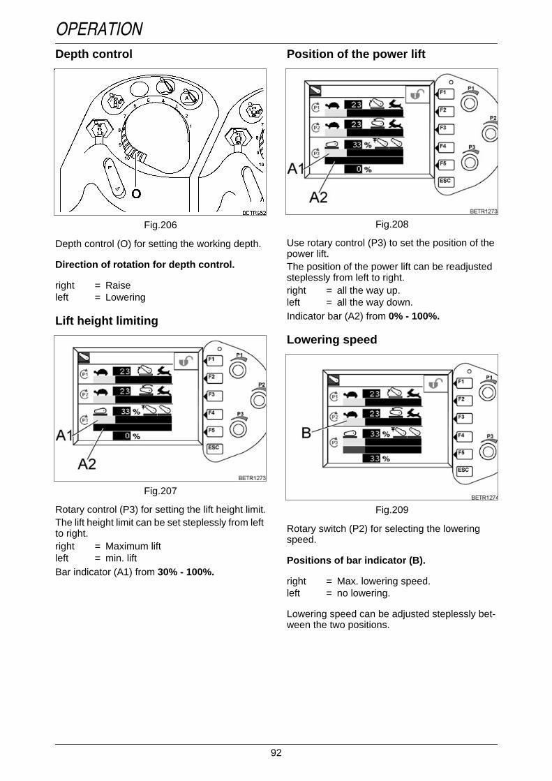
92
OPERATIONDepth control
Operation_Pic_number:1
Depth control (O) for setting the working depth.
Direction of rotation for depth control.
right = Raiseleft = Lowering
Lift height limitingOperation_Pic_number:1
Text-module
Rotary control (P3) for setting the lift height limit.The lift height limit can be set steplessly from leftto right.right = Maximum liftleft = min. liftBar indicator (A1) from 30% - 100%.
Fig.206
Fig.207
Position of the power liftOperation_Pic_number:1
Text-module
Use rotary control (P3) to set the position of thepower lift.The position of the power lift can be readjustedsteplessly from left to right.right = all the way up.left = all the way down.Indicator bar (A2) from 0% - 100%.
Lowering speedOperation_Pic_number:1
Rotary switch (P2) for selecting the loweringspeed.
Positions of bar indicator (B).
right = Max. lowering speed.left = no lowering.
Lowering speed can be adjusted steplessly bet-ween the two positions.
Fig.208
Fig.209

93
OPERATIONLift speed
Operation_Pic_number:1
Rotary switch (P1) for setting the lift speed.
Lift speed is controlled electronically and can beadjusted steplessly.
Positions of bar indicator (C).
right = Max. lift speed.left = No lifting.
Lifting speed can be adjusted steplessly bet-ween the two positions.
Front external controlsOperation_Pic_number:1
● The lifting gear can be raised or loweredusing buttons (A).
NOTE:The maximum hydraulic oil flow rate is ap-prox. 30 l/min.If the safety lock is actuated,External operation is possible at any positionof the Quick Lift switch.
Fig.210
Fig.211
DA/SA operationOperation_Pic_number:1
● Turn lever (A) - see label.
NOTE:Only use light implements (e.g. mowers)which are loaded without pushing, in the SAposition.
Fig.212

94
OPERATIONFloating position
Operation_Pic_number:1
● Quick Lift switch (P) at 'Control' (P1), LED islit.
● Move implement with depth control (O) to thedesired switch-on position.
● Quick Lift switch (P) at 'Raise' (P2), LED is lit.Operation_Pic_number:1
● Quick Lift switch at 'Control' (P1) (does notengage), LED is lit.
The power lift lowering movement is controlled,floating position is selected only when the posi-tion selected with the depth control is reached.Symbol (E) appears.
Press button.
Fig.213
Fig.214
Hitching three-point implementsOperation_Pic_number:1
● With rotary switch (P3), set 30 % lift, bar indi-cator (A1).
● Wait until indicator bar (A2) displays 0%.Operation_Pic_number:1
● Quick Lift switch (P) at 'Control' (P1), LED islit.
● Lower the lifting arms by turning the depthcontrol (O) to the left. To raise the lifting arms,turn the control to the right.
The upper and lower links are firmly attached tothe implement.
● Turn depth control (O) to '0' or quick lift switch(P) to 'Lift' (P2) (no lock), LED lights up. Theimplement is raised to the lift height limit (ap-prox. 1/4 of the total lift height).
● Using rotary switch (P3), the implement cannow be raised to the desired height.
Fig.215
Fig.216

95
OPERATIONUnlinking 3-point implements usingdepth control
Operation_Pic_number:1
● Turn depth control (O) fully to the right.● Quick Lift switch (P) at 'Control' (P1), LED is
lit.● With depth control (O), slowly lower the im-
plement till there is no load on the top link,then unhitch the implement.
● Release the catch hook and lower the hy-draulics completely.
Setting the desired transport heightOperation_Pic_number:1
● Lower the implement completely.● With rotary switch (P3), set 30 % lift, bar indi-
cator (A1).● Wait until indicator bar (A2) displays 0%.
Fig.217
Fig.218
Operation_Pic_number:1
● Quick Lift switch (P) at 'Raise' (P2), LED is lit.The implement is raised by about 1/4 of its liftheight.
● Using rotary switch (P3), select the desiredtransport height.
Road haulage (transport lock).● For road transport turn depth control (O) fully
to the right.
Fig.219

96
OPERATION
21. Trailing devices
21.1 Calculation of trailer weights
Diagram of permissible trailer weightOperation_Pic_number:1
Text-module
Calculating the permissible trailer weightC = T x Dt : (T - Dt) Example: 12 x 7.13 : (12 - 7.13) = 17.6Dt = D : 9.81 Example: 70 : 9.81 = 7.13Text-module
C = Permissible trailer weight (tonnes)T = Weight of tractor vehicle (tonnes)D = D-value (kN)
DANGER:Attach implements and trailers only to the points specified for this purpose.Do not exceed the maximum vertical bearing load on the coupling.Observe appropriate axle loads and weights, and follow the traffic regulations.Make sure trailer is correctly attached. Check that the trailer brake system isfunctioning. Follow the trailer manufacturers instructions!Carry out regular checks to ensure the trailer hitch is in perfect condition, especiallywhen subjected to heavy loads.The coupler is a design-approved component and may be used only for its designatedpurpose.Use only correct drawbar coupling-pin combinations. Use only the bolts provided.When converting to a mechanical or automatic coupling, ensure that the couplingcannot slip out of the guide rails unintentionally, by fitting a locking screw into thebottom hole.We reserve the right to make technical modifications. The details on the rating plateare binding.The maximum traction vehicle/trailer total weight of 40 tonnes must not be exceeded.If there are different values on the trailer bracket and trailer hitch rating plates, thelower value is the definitive value.
Fig.220

97
OPERATION21.2 Trailer bracket
Operation_Pic_number:1
Operation_Pic_number:1
Observe maximum permissible supporting loadand trailer load. (See rating plate.)
Fig.221
Fig.222
21.3 Hitching a trailer manuallyOperation_Pic_number:1
Moving the hitch coupling.● Raise handle (A) and move the coupling.
Operation_Pic_number:1
Observe maximum permissible supporting loadand trailer load. (See rating plate.)
Fig.223
Fig.224

98
OPERATION21.4 Automatic trailer coupling
Operation_Pic_number:1
Moving the hitch coupling.● Turn handle (A) upwards and press to the left.● Bring trailer hitch to the desired height.● Hold trailer hitch in floating position to allow
the locking bolt to lock in place; at the sametime turn handle (A) downwards and press tothe right.
Operating the trailer hitch.● Press handle (B) upwards until it locks.● Control stud (C).
Operation_Pic_number:1
Detaching the hitch coupling.● Demount remote control cable.● Pull pin (A).● Slide the coupling downward and out of the
guide rails.
DANGER:In secured position, handle (A)should only be able to be pressedapprox. 4 mm towards the opening.
DANGER:Control stud (C) should not protrudefrom the control sleeve aftercoupling.
Fig.225
Fig.226
Cylindrical pin versionOperation_Pic_number:1
Observe maximum permissible supporting loadand trailer load. (See rating plate.)
Version with crowned boltOperation_Pic_number:1
Observe maximum permissible supporting loadand trailer load. (See rating plate.)
Fig.227
Fig.228

99
OPERATIONRemote control
Operation_Pic_number:1
● The hitch coupling can be operated from thedriving seat using hand lever (A).
Fig.229
21.5 Ball coupling, drawbar, pi-ton fixText-module
(optional).Text-module
Ball coupling
NOTE:The use of ball coupling when travelling onthe public highway is only permitted if this isentered in the vehicle documents.The trailer must be equipped with a height-adjustable support.
Ball couplingOperation_Pic_number:1
After coupling, secure locking clamp with bolt(A), fit safety lock (B).
Ball coupling height adjustableOperation_Pic_number:1
Moving the hitch coupling.● Press handle (A) upwards and to the right.● Bring trailer hitch to the desired height.● Hold trailer hitch in floating position to allow
the locking bolt to lock in place; at the presshandle (A) to the left.
● After coupling, secure locking clamp with bolt(A), fit cotter pin (B).
Fig.230
Fig.231

100
OPERATION
Operation_Pic_number:1
To reduce wear, make sure the foam ring (A) isfitted.
The permissible vertical play (0.5 mm - 1.0 mm)can be set with the locking clamp.
To reduce wear, lubricate the contact surfaces ofthe ball coupling and hitch mechanism regularly.
After operation, cover ball with cap.
Ball couplingOperation_Pic_number:1
Observe maximum permissible supporting loadand trailer load. (See rating plate.)
DANGER:In secured position, handle (A)should only be able to be pressedapprox. 4 mm towards the opening.
Fig.232
Fig.233
Ball coupling height adjustableOperation_Pic_number:1
Observe maximum permissible supporting loadand trailer load. (See rating plate.)
Ball coupling height adjustableOperation_Pic_number:1
Observe maximum permissible supporting loadand trailer load. (See rating plate.)Text-module
Fig.234
Fig.235

101
OPERATIONDraw barNOTE:The use of a drawbar is recommended for im-plements only.Due to the excessive play, not suitable as atrailer hitch on public roads.
Operation_Pic_number:1
When the bearing bracket (A) is mounted,tighten screws (B) with 580 Nm.
Operation_Pic_number:1
The pull rod can be inserted in different holes.Unscrew safety device. Remove pin (A).
Maximum carrying power (suppor-ting load)
Operation_Pic_number:1
Do not exceed the maximum permissible verticalload and positon on public roads (see modelplate).
Fig.236
Fig.237
Fig.238
Operation_Pic_number:1
Text-module
● The bar travel to the left or right can be movedand/or fully opened by removing both bolts(B).
● Coupler height can be adjusted by invertingthe drawbar (A).
NOTE:On public roads, lock the drawbar with withpin (B).
Operation_Pic_number:1
If coupling jaw (A) has been removed, mount theintermediate panel (B) if attaching it again.
Observe the specified torques.Operation_Pic_number:1
Observe maximum permissible supporting loadand trailer load. (See rating plate.)
Fig.239
Fig.240
Fig.241

102
OPERATIONPiton fix
Operation_Pic_number:1
Text-module
NOTE:The trailer must be equipped with a height-adjustable support.
Operation_Pic_number:1
Observe maximum permissible supporting loadand trailer load. (See rating plate.)
Fig.242
Fig.243
21.6 Hydraulic trailer hitchText-module
(optional).Text-module
NOTE:The use of a hydraulic automatic coupling onthe road is permissible only if an appropriateentry has been made in the vehicle docu-ments.Observe safety and operating instructions(see OPERATION Section 17.8).Text-module
OperatingOperation_Pic_number:1
● Connect hydraulic lines to the desired hy-draulic connection at the rear, e.g. greenvalve (D).
Operation_Pic_number:1
● Lift/lower hydraulic trailer hitch with key (D).
DANGER:Risk of serious injury in the areaaround the three-point link and lif-ting rods!When coupling or uncoupling, re-lease the trailer and/or tractor bra-kes.Tractor or trailer may move back-wards or forwards. Never stand be-hind or in front of either one of them.Danger of crushing!Lock of hitch hook must snap in.
Fig.244
Fig.245

103
OPERATIONLowering
Operation_Pic_number:1
● Before lowering, release lock with lever (A).● Lower hitch hook.
Operation_Pic_number:1
● Lock the hydraulic trailer hitch into parkingposition (arrowed) after finishing work to allowother use of the hydraulic connection.
Operation_Pic_number:1
Observe maximum permissible supporting loadand trailer load. (See rating plate.)
Fig.246
Fig.247
Fig.248
MaintenanceOperation_Pic_number:1
Lubricate hydraulic trailer hitch every 100operating hours at the lubrication points(arrowed).Text-module
Lubrication pointsA = lower hitch, 2 lubrication points.B = lower hitch, 2 lubrication points.C = unscrew cover, 2 lubrication points.D = to the left and right of the catch hook, 2 lubri-
cation points.E = on hitch hook, 1 lubrication point.F = underside of hitch, 4 lubrication points.G = underside of hitch, 4 lubrication points.H = unscrew cover, 1 lubrication point.
Fig.249

104
OPERATION
22. Compressed air sy-stem
Operation_Pic_number:1
Correct operating pressure is reached if the 6pressure indicator bars (C) are shown.
Insufficient operating pressure is indicated by aflashing bar indicator.
DANGER:Make sure trailer is correctlyattached. For trailers with air brakes,start driving only the 3 bar indicatorsare visible on display (C) and thereare no warning messages!Observe trailer manufacturer'sinstructions.Whenever towing trailers equippedwith air brakes, do not useindependent wheel brakes (lock thebrake pedals)!
Fig.250
22.1 OperatingOperation_Pic_number:1
A = 'Black' coupling headConnector for single-line system.
B = 'red' coupling headDual-line system supply.
C = 'Yellow' coupling headDual-line system, brakes.
● After uncoupling, seal the openings with thedust caps.
Antifreeze pump/tankOperation_Pic_number:1
If frost is expected:● Set antifreeze pump lever (A) to I = open.● Fill antifreeze tank (B) with ethyl alcohol
(X 902.015.003).
At the end of the cold season:● Set lever to 0 = closed.Text-module
Filling tyres● Connect the supplied tyre inflating hose to red
coupling head.
IMPORTANT:Regularly check pressure which can rise toabout 8.1 bar.
Fig.251
Fig.252
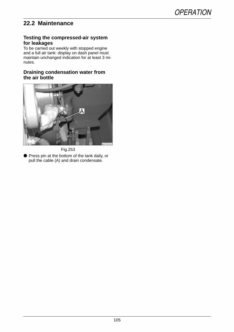
105
OPERATION22.2 MaintenanceText-module
Testing the compressed-air systemfor leakagesTo be carried out weekly with stopped engineand a full air tank: display on dash panel mustmaintain unchanged indication for at least 3 mi-nutes.
Draining condensation water fromthe air bottle
Operation_Pic_number:1
● Press pin at the bottom of the tank daily, orpull the cable (A) and drain condensate.
Fig.253

106
OPERATION
23. Additional ballasting
23.1 Front ballastText-module
Attachment plate 117 kg:3 pcs. maximum.Can only be fitted to tractors without front powerlifts.
Operation_Pic_number:1
NOTE:With the 117 kg attachment plate, fit lock (A).Text-module
Hanging weights approx. 42 kg:Max. of 10.Can only be fitted to tractors without front powerlifts.An attachment plate is required so that they canbe hung.
DANGER:Always make sure there is sufficientweight on the front axle when usingrear-mounted implements. Tomaintain brake effectiveness andsteerability, the front axle must beloaded with at least 20% of theunladen weight of the tractor.Always fit weights in the fixingpositions provided as per theinstructions.Do not exceed the permissible totalweight or axle load (see rating plateor vehicle documents). When usingballast weights, make sure of correcttyre pressures!
Fig.254
23.2 Front/rear load weightsText-module
Ballasting weight 1,800 kg
Front/rear weight 870 kgOperation_Pic_number:1
A = Fastening point of top link.B = Fastening point for top link with quick-re-
lease coupling.C = Attachments for packer transport (sin-
gle-row packer max. 1,000 kg).Additional weights are not possible.
NOTE:870 kg weight can also be supplemented by 3x 117 kg attachment plates or 8 x 42 kg waferplates. Observe permissible front axle loads.
Fig.255

107
OPERATION23.3 Wheel weights
Max. 4 x 295 kg may be mounted.Operation_Pic_number:1
A = Starting torque 210 Nm.B = When replacing screws, new screw
length 95 mm.Starting torque 600 Nm.
NOTE:No wheel load weights must project over thetyres, otherwise they cannot be used on thepublic highway.
WARNING:Observe the maximum permissiblewidth indicated in the vehicledocuments.
Fig.256
23.4 Water ballasting of tyresOperation_Pic_number:1
A = Fill with water.B = Drain water.L = Air.W = Water.
Follow tyre manufacturer's specifications with re-gard to volumes (water + antifreeze solution).Check tyre pressures regularly.
Fig.257

108
OPERATION
24. Track adjustment
24.1 Lighting wide vehicleOperation_Pic_number:1
Apply left and right warning signs flush with theouter edge of the tyre.
Tighten locking screw (A) at 5 Nm.
DANGER:When working on tyres, make surethe tractor is properly parked andsecured against rolling away (wheelchocks)!If the engine needs to be started forturning the wheels, both wheelsmust be jacked up and turn free.When the tractor is jacked up andsome one is working underneath, noone else should be on the tractor.If the tractor is lifted with the lowerlinks, additional supports arerequired!Tyre repairs should be performedonly by qualified personnel usingsuitable tools.Tyres may explode if the air pressureis too high! Check tyre pressuresregularly!Do not use special protective tyresfor heavy-duty traction work or frontloader operations; maximum roadspeed 25 km/h.After wheel mounting or trackadjustment, tighten the bolts andnuts on front and rear wheels and ontrack adjusting elements. Checkthese regularly!
Fig.258
24.2 Rear axle stubText-module
(optional).
Change track widthOperation_Pic_number:1
Jack up rear wheels, loosen screws (A).
Screw in the screws (in tool box) in hole (B) toloosen the chuck cone.
Set to the desired track width.Operation_Pic_number:1
If the track width is changed, the mounting boltsshould be tightened in accordance with thefollowing diagram.1 = Tighten hexagon screws in the order
shown (1-6) at a torque of 200 Nm.2 = Tighten hexagon bolts to Nm in the order
shown (1-6).3 = Drive tractor for a couple of hundred
yards then retighten to 600 Nm in the or-der shown (1-6).
4 = After another 3 operating hours, re-tighten in the order shown (1-6), to600 Nm.
5 = After 10 additional operating hours re-tighten according to the shown pattern(1-6) at 600 Nm.
Fig.259
Fig.260

109
OPERATIONReplacing rims with rear axle stub
Operation_Pic_number:1
NOTE:If changing the rims, check that washers (A)are present.
Fig.261

110
OPERATION
25. Twin tyres
Twin tyres may be used to reduce ground pressure but not to increase load capacity or pulling power.Text-module
NOTE:For use on public roads, twin tyres must be indicated in the vehicle registration documents. Thetwin tyre selection table in this manual may be used when presenting the tractor at a vehicle te-sting station.
WARNING:When working on tyres, make sure the tractor is properly parked and secured againstrolling away (wheel chocks)! When the tractor is jacked up and some one is workingunderneath, no one else should be on the tractor.See also safety directions in Track width adjustment. For tightening torque, see TECH-NICAL DATA.
25.1 Conditions for useOperation_Pic_number:1
Fig.262
● If the standard lights are more than 400 mmfrom the vehicle outer edge, tail lights, sidelights and reflectors must be duplicated. If ne-cessary, fit marker lights.
● In excess of 2,750 mm width, fit warning pla-tes front and rear.
● Max. ground speed 25 km/h (as per vehicle li-censing regulations if wheels have insufficientcovering).
25.2 Twin tyresText-module
2 x standard tyres
* Permissible axle load on request, only HD system from Grasdorf approved.** for 924 - 930 only.Text-module
Twin wheels cannot be used as single tyres. Consult mounting instructions of the manufacturer of twintyres.Ordering and delivery information by:Fa. Metallbau Grasdorf GmbH, Ziegelei Straße 29, 31188 HolleTelephone +49 (0) 5062/902-0, Fax +49 (0) 5062/902-139
Inner tyre track2000
Outer tyres * Inner tyre track1970
Outer tyres *
480/70-R34 480/70-R34 580/70-R34 20.8-R42480/70-R34 16.9-R34 580/70-R34 580/70-R34520/70-R34 520/70-R34 620/70-R42 20.8-R42520/70-R34 18.4-R34 620/70-R42 620/70-R42600/65-R34 600/65-R34 650/65-R34 20.8-R42600/65-R34 18.4-R34 650/65-R34 650/65-R34600/65-R34 600/65-R34 680/85-R38** 680/85-R38**600/65-R34 600/65-R34 710/70-R42** 710/70-R42**

111
OPERATION
26. On-board computerText-module
Functions of the on-board informa-tion system:E = Setting time.F = Calibrating speed display.G = Fault display.
Operation_Pic_number:1
Text-module
On-board computer keypad:
NOTE:Before using the on-board computer, any exi-sting fault messages must be cancelled (seealso FAULTS AND REMEDIAL ACTIONS Sec-tion 1.3).
Text-module
Other keypads
On-board computer - opening or exiting afunction.
The multiple display switches from standarddisplay (clock, operating hours) to computerfunctions.
Up or down to select the desired function.
Confirm, set or disable the selectedfunction.
Return to previous function.
Terminating all on-board informationsystem function on each function level.
'Quit' key (see also FAULTS ANDREMEDIAL ACTIONS Section 1).
Entering tyre size (see also OPERATIONSection 26.4) and calling the servicefunction (settings carried out at workshop).No function.
Open the EPC Service function (settingfunction for the workshop).
Fig.263
26.1 Setting the clockOperation_Pic_number:1
26.2 Adjusting speed indicatorCalibration allows the speed display to be accu-rately adjusted to field conditions, e.g. whenoperating with mounted implements or in theevent of tyre wear.Text-module
NOTE:Use only the clutch pedal to drive the tractorduring the calibration process.If driving with the joystick, the ACTIVE sym-bol, which appears when stopping at markerpoints, cancels the menu-assisted adjust-ment process.● Measure and mark an exact distance bet-
ween 30 meters (minimum) and 100 meters(maximum).
Operation_Pic_number:1
Press key - function selection is displayed.
Press one of the keys repeatedly until theset clock symbol (E) flashes.
Press key - screen (J) appears, 1st digit (K)flashes.
Press repeatedly one of the keys until thedesired digit shows.
Press button. Set consecutively remaining3 digits the same way as the 1st digit.
Press (ESC) key twice (new time is shownon the multiple display).
Press key - function selection is displayed.
Fig.264
Fig.265

112
OPERATION
● Move the tractor to position the front wheelexactly at the start mark.
Operation_Pic_number:1
● Start the tractor off, and stop with the frontwheels at the end mark of the measured di-stance.
● Check whether the measured distance andthe input distance are the same.
● If necessary, enter measured distance asdescribed previously and repeat calibrationprocedure.
Press one of the keys repeatedly until the'Adjust speed indicator' symbol (F) flashes.
Press key - screen (J) appears. 1st digit ofthe distance flashes.
The measured distance must now be entered,e.g. 50 m.
Press one of the keys repeatedly until thedesired digit is displayed, e.g. 0.
Press button. Set the other 2 digits oneafter another as with 1st digit, e.g. 050.
After confirming the last digit, START will flash.
Press key, the display changes from'START' to 'STOP'.
Press button. If the process was completedcorrectly, an 'OK' message appears.
Press key - clock and operating hours aredisplayed.
If an 'ERROR' message is displayed, repeat theadjustment process as follows:
Press key, data entered for the measureddistance is displayed.
Press key - clock and operating hours aredisplayed.
Fig.266
26.3 Fault displayWhen a fault occurs, an error code is stored.These codes can be called up by the workshopfor prompt error diagnosis.
Operation_Pic_number:1
Text-module
Displaying stored fault codes
The following are displayed:
K = Number of stored fault codes (maximum50).
L = Number of the displayed fault code.M = Fault code.
26.4 Selecting tyre sizeIf the tyre size is changed, the speed indicatorcan be quickly adapted to the new tyre size.Text-module
Input value:The rolling circumference of the rear tyres mustbe entered in mm.
NOTE:Rolling circumference can vary according totyre size. Comply with tyre manufacturer’s re-commendations.
Press key - function selection is displayed.
Press key repeatedly until 'Fault Display'symbol (G) flashes.
Press key - screen (J) is displayed.
Press one of the keys repeatedly to showthe stored fault codes one after the other(also see FAULTS AND REMEDIALACTIONS Section 5).
Press key - clock and operating hours aredisplayed.
Fig.267

113
OPERATIONOperation_Pic_number:1
Text-module
L = Enter tyre size.M = PTO clutch (rear/front) adjustment
function.Text-module
Text-module
● Switch ignition OFF and ON (reset).
New value is stored.
26.5 Backup indicatorsIf one of the direction of travel indicator lampsfails.Text-module
Text-module
Activating the backup indicatorAfter removing all warning or fault codes, thebackup display will be automatically activated.How to clear the fault messages (see FAULTSAND REMEDIAL ACTIONS Section 1.3).
Text-module
Press key - image (K) is displayed, symbol(L) flashes.
Press key - screen (N) is displayed, 1st digit(O) flashes.
Press repeatedly one of the keys until thedesired digit shows.
Press button. Set consecutively remaining3 digits the same way as the 1st digit.
Press button.
forward
reverse
a fault will be shown in the multiple display. Abackup indicator can be activated until the faultyindicator lamp is replaced.
By pressing the key, the time and operatinghours display is shown for a period of 5 sec.
If within 5 seconds, the key is pressed a secondtime, the functions of the on-board computer willbe displayed.
Fig.268
Backup display symbolsForward selected.
Forward engaged.
Reverse selected.
Reverse engaged.
Forward engaged, reverseselected.
Reverse engaged, forwardselected.

114
OPERATION
27. Computer27.1 Computer functions
Operation_Pic_number:1
Operation_Pic_number:1
● Connect external counter plug in blue socket(D).
Text-module
The individual measuring/counting process canbe made subject to a certain condition, as fol-lows:Measurement or counting only conducted if:
ETNum-list
Fuel consumption
Distance measurement
Area measurement
Stop watch
External counter
The signal from the on-board computer ispassed through an external counting sensor(e.g. on baler, sprayer).
1.PTO (rear/front) is activated.2. lifting gear (rear/front) is lowered.3.external counter switch closed.
Fig.269
Fig.270
27.2 Select main menuOperation_Pic_number:1
Text-module
Symbol (A) shows whether one or several com-puters are activated in background.Text-module
● Press key (F5). The following sub-menu ap-pears.
Operation_Pic_number:1
Text-module
● Press key (F1). The following submenu appe-ars.
Operation_Pic_number:1
The main menu shows the measured andcounted data.
NOTE:Press ESC to return to previous menu level.
Fig.271
Fig.272
Fig.273

115
OPERATION27.3 Setting measurement andcounting direction
Operation_Pic_number:1
Text-module
● Press key (F1). The following submenu appe-ars.
Operation_Pic_number:1
Text-module
Press key (F1), select between:Real speed(Radar sensor).
Theoretical speed (themeasurement result is distorted ifthere is wheel slip).
Press key (F2), select between:Measurement only available withforward travel(Standard setting).
Measurement only when travellingin reverse.
Measurement only in forward travel(in reverse, the calculation issubtracted).
Fig.274
Fig.275
Text-module
NOTE:Press ESC to return to previous menu level.
27.4 Manually triggered measu-ring and counting
Operation_Pic_number:1
Text-module
● Press key (F2 or F3 or F4 or F5) (location1 - 4). The following submenu appears.
Operation_Pic_number:1
Measurement only in reverse (inforward travel, the calculation issubtracted).
Measurement in forward andreverse.
Set trailed implement width withrotary control (P1).
Fig.276
Fig.277

116
OPERATION
Text-module
NOTE:Before an average fuel consumption measu-rement is carried out, reset measurement rea-ding to "0" to get a meaningful average.Text-module
NOTE:Press ESC to return to previous menu level.
27.5 Operating automatic mea-surement and counting
Operation_Pic_number:1
Text-module
● Press key (F2 or F3 or F4 or F5) (location1 - 4). The following submenu appears.
Activating / Deactivating measurement andcounting function.
Press key (F3) to activate ordeactivate the fuel consumptiondisplay.LED (C) is lit green whenmeasurement is active.Display for average fuelconsumption (D), litres per hectare.
Press key (F2) to switch on/off.If the measuring and countingfunction is active, LED (A) lights up.The LEDs (B) are lit (for informationonly) if the front/rear power lift ofthe front/rear PTO and the eventcounter is operated.
Resetting on-board computer functions andfuel consumption indicator to "0".
Press key (F5) - all values are resetto '0'. Only possible if nomeasurement is running - exceptthe fuel consumption indicator.
Fig.278
Operation_Pic_number:1
Text-module
● Press key (F1). The following sub-menu ap-pears.
Operation_Pic_number:1
Function indicatorsA = Front power liftB = Rear power liftC = Front PTOD = Rear PTOE = Event counter
Text-module
Set trailed implement width withrotary control (P1).
Select forward or reverse measurement.To toggle, press key (F2).
Activate lifting gear measurement (can alsobe combined with PTO measurement and/orexternal counter).
To activate, press key (F3). Whenactivated, the symbol has a greenbackground.Measuring and counting only iflifting gear is switched to 'Control'(lowering).
Fig.279
Fig.280

117
OPERATIONText-module
NOTE:Press ESC to return to previous menu level.
28. Storing the settingsText-module
This setting saving function allows four differentsets of parameters to be saved and named un-der any name and recalled when needed.
28.1 Setting that can be savedText-module
Comfort front power lift● Lock status● Cross adjustment - floating setting● Lift flow regulation● Lower flow regulation● Maximum lifting heightText-module
Rear power lift (EPC)● Lock status● Slip control status● Lowering speed● Mix ratio (position/traction control)● Wheel slip setting● Switch-on speed for vibration damping● Maximum lifting height● Automatic functionText-module
Rear PTO● Rear PTO rpm● Automatic functionText-module
Electrical valves 1-4● Valve priority● Lock status● Kick-out status
Activate PTO measurement (can also becombined with lifting gear measurementand/or external counter).
To activate, press key (F4) - thegreen symbol indicates activestatus.Measuring and counting onlyavailable with rear or front PTOengaged.
Activating external counter input.Connect cable (ID. No. 0071 023100) to blue socket (see pictureOPERATION Fig. 270).To activate, press key (F5). Whenactivated, the symbol is lit green.Measuring and counting onlypossible if there is a sealedcounting sensor on the implement(e.g. hydraulic fertiliser spreader)and this is connected to theon-board computer.
● Timer setting● Lift flow regulation● Lower flow regulation● Timer function selectionText-module
External valve actuation● Valve selection (3rd valve or 4th valve)Text-module
Load limit control● Engine speed drop set valueText-module
Cruise control● Tempomat cruise control speed 1● Tempomat cruise control speed
pre-selection 1● Speed cruise control 2● Tempomat cruise control speed
pre-selection 2Text-module
Quick reverse● Reversing speedText-module
Electronic accelerator● Min/Max engine speed valuesText-module
4WD● 4-WD pre-selectionText-module
Differential lock● Pre-select differential lockText-module
Suspension● Suspension mode pre-selectionText-module
Tractor Management System (TMS)● TMS operation ON● Accelerator mode ON● Set engine speed range● Operating status (PTO, power lift, hydraulic
valve function) of the engine speed controlText-module
Variotronic Ti● Stored operating sequences available for
play back

118
OPERATION28.2 Saving names and settingsEngine must be running to allow a setting to besaved.
Operation_Pic_number:1
● Press key (F5) - the next screen is displayed.Operation_Pic_number:1
Operation_Pic_number:1
If the name consists of question marks only, noparameters have been stored in this memorylocation.
Press key (F2). The followingsub-menu appears.
Fig.281
Fig.282
Fig.283
Operation_Pic_number:1
Text-module
The following submenu appears.
Press key (F5). The followingsub-menu appears.
Key (F1) to select memorylocations 1 - 4.
Key (F2) to select the location ofinput characters (letters ornumbers).
Press key (F3) to scroll characters(letters or numbers) forward (onecharacter at a time).
Key (F4) scrolls the characters(characters or numbers) backward(one character a time).
Quick scroll (selection) forward orbackward through characters(letters or numbers), severalcharacters at a time.
Use key (F5) to save settings.
Settings are stored at the selected memorylocation under the selected name.
Fig.284

119
OPERATIONOperation_Pic_number:1
Text-module
The following submenu appears.Operation_Pic_number:1
NOTE:Use the ESC key to return to the previousfunction levels.
Fig.285
Fig.286
28.3 Calling up settingsOperation_Pic_number:1
● Press key (F5) - the next screen is displayed.Operation_Pic_number:1
Operation_Pic_number:1
With keys (F1 - F4) select the set of parametersto be loaded.
Following screen appears.
Press key (F2) - the followingsubmenu is displayed.
Fig.287
Fig.288
Fig.289

120
OPERATIONOperation_Pic_number:1
The following sub-menu then automaticallyappears. Settings are stored.
Operation_Pic_number:1
If the parameters are loaded successfully, acheckmark appears next to the memory location.
The following sub-menu then automaticallyappears.
NOTE:Engine must be running with the transmis-sion in neutral position.
Operation_Pic_number:1
● Press key (F2). The Variotronic Ti menu ap-pears. For further description (see OPERA-TION Section 30).
● Press key (F3) to return to first main menu.
Fig.290
Fig.291
Fig.292
29. Implement controlText-module
With the implement control, the existing controlson the tractor (operating terminal, joystick) canbe used for operating the attached implement.Text-module
ESC keyThe ESC key has a double function in implementcontrol.
29.1 Assigning control terminalText-module
An LBS control terminal can also work via a se-parate control terminal, e.g. Fieldstar, thereforethe system must be informed which control ter-minal is to be used.
Operation_Pic_number:1
● Press key (F5). The following sub-menu ap-pears.
Press key once (for about 1 sec.) to returnto previous function level.
Press key twice to toggle between lastselected tractor menu and last selectedimplement control menu.
This function only works if there is an activemounted implement.
Fig.293

121
OPERATIONOperation_Pic_number:1
● Press key (F5). The following sub-menu ap-pears.
Operation_Pic_number:1
Text-module
● Press key (F4). The following sub-menu ap-pears.
Operation_Pic_number:1
Fig.294
Fig.295
Fig.296
Press key (F5) - select between:
NOTE:Settings are active after exiting the submenu.
LBS control terminal andFIELDSTAR control terminal.
LBS control terminal.
Deactivating implement control.
ISO control terminal.
LBS control terminal or ISO controlterminal.

122
OPERATION29.2 Loading the implementsoftware for implement controlText-module
Ignition OFF. Connect the mounted implement tothe tractor using the LBS socket.Ignition ON.The following menu quickly appears in the con-trol terminal.
Operation_Pic_number:1
After approx. 30 seconds, download will beinitiated automatically.
The F1 key can be used to start the loadingprocess immediately.
The ESC key can be used to abort the loadingprocess.Text-module
Once the downloading process has started, thefollowing menu appears in the control terminal.
Operation_Pic_number:1
Indicator bar (A) Red: progress of memoryerasing.
Bar indicator (A) Green: progress of datatransfer from the implement to the operatingterminal.
If downloading has been successful, thefollowing image appears.
Fig.297
Fig.298
Operation_Pic_number:1
If downloading has been successful, thefollowing image appears (A).
Operation_Pic_number:1
NOTE:Up to four working implements can be stored.If the data memory is full, the data for the im-plement not used for the longest time are de-leted.
If the loading process is not successful, thefollowing menu appears on the control terminal.
Operation_Pic_number:1
Press key F1 to re-start the loading process.
Press key ESC to abort the loading process.
Fig.299
Fig.300
Fig.301

123
OPERATIONNOTE:Check connections and the fuses in case ofrepeatedly unsuccessful download attempts.Disconnect and reconnect the implementfrom and to the LBS/ISO socket.Restart tractor.
29.3 Setting up the control ter-minal for implement control
Operation_Pic_number:1
● Press key F5. The following sub-menu appe-ars.
Operation_Pic_number:1
Text-module
The control terminal shows:
NOTE:Appears shortly, as soon as the control termi-nal has successfully logged onto the LBS-ISO bus.Text-module
LBS-ISO implement active.
One or more implements arealready stored in implementcontrol.
Fig.302
Fig.303
Press F3 key.
The start menu for the connected implement(e.g. forage box).
Operation_Pic_number:1
● Select/activate the joystick and connected im-plement with the F1 - F4 keys.
Text-module
Function displaysNone = no implement is stored.Blurry = implement is stored but not active.White = implement active without joystick.Green = implement active with joystick.Strikethrough = implement can not be assigned.
Vario terminal deactivated as anLBS-ISO control terminal, noimplement control possible.
Fig.304

124
OPERATION29.4 Operating the implementwith the joystick
Operation_Pic_number:1
Text-module
● Assign joystick with the F1- F4 keys.● To change the control button assignment,
press the F5 key.
NOTE:The following sub-menu appears only for ISOimplements for which the control button as-signment can be changed.
Operation_Pic_number:1
A = Connected implement, e.g. hay wagon.B = Function of the connected implement,
e.g. lower pickup, lift pickup, lower draw-bar.......
Text-module
Text-module
The button which is to trigger afunction is selected with the rotarycontrol (P2).
Browsing forward in the selectionmenu is also possible with therotary control (P3).
Browsing backward in the selectionmenu is also possible with therotary control (P3).
Fig.305
Fig.306
Text-module
Text-module
Text-module
NOTE:Go back to the previous function level withthe ESC key, without saving.
Automatic assignmentOperation_Pic_number:1
1 - 10 = First, second........ function on the imple-ment.
NOTE:For the operation of implements with the con-trol terminal, consult the implement manufac-turer's operating manual.
Automatic assignment ofimplement functions to a joystickcontrol button (see OPERATIONFig. 307).
No joystick control buttonassignment, set new assignment.
Go back to previous selectionpage, with saving the controlfunctions.
Fig.307
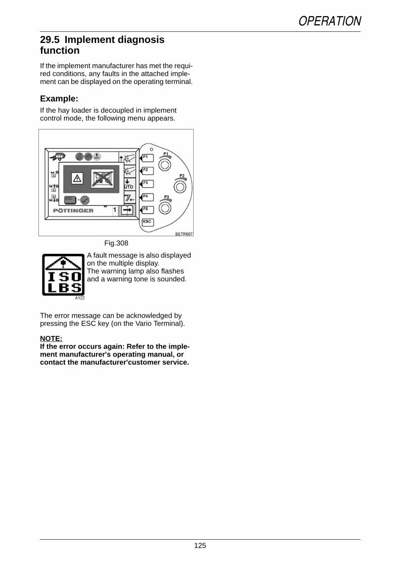
125
OPERATION29.5 Implement diagnosisfunctionText-module
If the implement manufacturer has met the requi-red conditions, any faults in the attached imple-ment can be displayed on the operating terminal.
Example:If the hay loader is decoupled in implementcontrol mode, the following menu appears.
Operation_Pic_number:1
Text-module
Text-module
The error message can be acknowledged bypressing the ESC key (on the Vario Terminal).
NOTE:If the error occurs again: Refer to the imple-ment manufacturer's operating manual, orcontact the manufacturer'customer service.
A fault message is also displayedon the multiple display.The warning lamp also flashesand a warning tone is sounded.
Fig.308

126
OPERATION
30. Variotronic TiThe TeachIn function enables repetitive operational sequences to be saved and retrieved when nee-ded.An individual set of functions and relative factors can be selected (e.g. an engagement/disengagementpoint can be selected for the rear PTO according to distance, time, lift height, or can be selected ma-nually by pressing a button).Text-module
NOTE:On the driver seat is a start-off protection. If the driver's seat is unoccupied for more than 3 se-conds, the pull-away cut-out is activated. Variotronic Ti functions cannot be played back.If a function or a trigger is required during recording, which is not already in the configurationlist, adapt the configuration list (see OPERATION Section 30.9).
30.1 FunctionsText-module
Rear power lift(Raise, Control, Stop, Fast feed-in).
Front power lift(Raise, Control, Stop, Floatingposition).
Rear PTO(ON - OFF).
Front PTO(ON - OFF).
Electric hydraulic valves(Raise, Lower, Stop, Floatingposition).
Vario transmissionCruise control (ON - OFF).
4-WDAutomatic mode, 100%, OFF.
Differential locksAutomatic mode, 100%, OFF.
Electronic engine control(ON-OFF, calling up stored enginespeeds).
30.2 TriggersText-module
NOTE:'RED' light = function active.'GREY' light = function not active.
Distance(travelled).
Time(elapsed).
Manual(by pressing the button).
Lift height of rear power lift.
Lift height of front power lift.

127
OPERATION30.3 Menu functions
Record menu level 1Operation_Pic_number:1
Key (F1) or rotary control P1.Change the button assignments onthe joystick for the controls(Record, Start, Stop, Pause etc.).
Different operating sequences can be assignedto all four buttons on the joystick.
Key (F2)To change to Playback menu.
Key (F3)To modify the configuration lists(see OPERATION Section 30.9).
Key (F4)End Variotronic Ti.
Key (F5)To change to another menu level.
Fig.309
Record menu level 2Operation_Pic_number:1
Key (F1) load operationalsequence from memory (see OPE-RATION Section 30.6).
Key (F2)Storing an operating sequence inmemory (see OPERATIONSection 30.5).
Key (F5)To change to another menu level.
Fig.310

128
OPERATIONPlayback menu level 1
Operation_Pic_number:1
Key (F1) or rotary control P1.to change assignment of joystickkey with which operation (record,start, stop, pause, etc.) iscontrolled.
Key (F2)To change to Record menu level.
Key (F3)To change relative factors (seeOPERATION Section 30.8).
Key (F4)End Variotronic Ti.
Key (F5)To change to another menu level.
Fig.311
Play menu level 2Operation_Pic_number:1
Key (F1) load operationalsequence from memory (see OPE-RATION Section 30.6).
Key (F2) to save operatingsequence to memory (see OPERA-TION Section 30.5).
Key (F3)Run through operational sequencemanually (see OPERATION Sec-tion 30.7).
Key (F5)To change to another menu level.
Fig.312

129
OPERATION30.4 Operating
NOTE:If travelling at more than 25 km/h, playback(Play) is not possible.Recording of an operational sequence bet-ween two activations is limited to 120 se-conds and/or 300 metres.If recording is interrupted for longer than2 minutes, recording is discarded.The direction of travel selected for the recor-ding must correspond with the direction oftravel selected when playing back. Travellingforward and being stopped are consideredthe same.If the playback of a recording is required inthe other direction of travel. Record with(Edit), see OPERATION Section 30.8, start,drive in other direction, new direction of tra-vel is saved.Text-module
Operation_Pic_number:1
● Press key (F5). The following sub-menu ap-pears.
Operation_Pic_number:1
● Press key (F4). The following sub-menu ap-pears.
Fig.313
Fig.314
Record menu levelOperation_Pic_number:1
or
Play menu levelOperation_Pic_number:1
Text-module
To record operational sequence.Up to 13 functions can be put together to form anoperational sequence.
In the next example:● Automatic function power lift and PTO.
The rear power lift is lowered, the rear PTO isengaged at a selected lift height of the rearpower lift. The rear power lift is lifted, the PTO isdisengaged at a selected lifting height of the rearpower lift.
Press key (F2)Change to menu level Record.
Fig.315
Fig.316

130
OPERATIONUnlock EPC, select PTO
Operation_Pic_number:1
● Start tractor.● Unlock rear EPC with quick lift key (A).● Select rear PTO speed using button (B).
Joystick key assignmentOperation_Pic_number:1
● Use rotary switch (P1) or● F1 key to specify which joystick button is used
for an action (Record, Start, Stop, Pause,etc.).
The active button on the joystick is shown in co-lour on the Vario terminal.
Fig.317
Fig.318
Operation_Pic_number:1
● Press the selected joystick button (A).● Display (B) changes from START to STOP.
Start recordingOperation_Pic_number:1
● Lower the rear lifting gear using Quick Liftswitch (A), to the position set with the depthcontrol (B).
● At the desired engagement point for the rearPTO, press button (C).
● Press selected joystick button (D) and recor-ding is ended.
When recording has ended, the following sub-menu appears on the Vario terminal.
Fig.319
Fig.320

131
OPERATIONPlay menu level
Operation_Pic_number:1
● Indicator (A) for operation with joystick button(when the selected joystick button is pressed,playback starts immediately).
● Indicator (B) for rear lifting gear.● Indicator (C) for rear PTO.● Indicator (D) for relative factor for the rear
PTO / rear lifting gear lift height.Text-module
Recording the second operating se-quence
Joystick key assignmentOperation_Pic_number:1
● Use rotary switch (P1) or● F1 key to specify which joystick key is used to
control operation (record, start, stop, pause,etc.).
The active button on the joystick is shown in co-lour on the Vario terminal.
Press key (F2). The followingsubmenu appears.
Fig.321
Fig.322
Record menu levelOperation_Pic_number:1
Operation_Pic_number:1
● Press the selected joystick button (A).● Display (B) changes from START to STOP.
Start recordingOperation_Pic_number:1
● Lift rear lifting gear to the desired height withthe quick lift key (A).
● At the desired disengagement point for therear PTO, press button (C).
● Press selected joystick button (D) and recor-ding is ended.
● Switch off rear lifting gear with the Quick Liftswitch (A).
When recording has ended, the following sub-menu appears on the Vario terminal.
Fig.323
Fig.324
Fig.325

132
OPERATIONPlay menu level
Operation_Pic_number:1
● Indicator (A) for operation with joystick button(after the selected joystick button is pressed,playback starts immediately).
● Indicator (B) for rear lifting gear.● Indicator (C) for rear PTO.● Indicator (D) for relative factor for the rear
PTO / rear lifting gear lift height.
PlaybackOperation_Pic_number:1
Press button (A)● Rear lifting gear is lowered, the rear PTO is
engaged at the selected lift height.
Press button (B)● Rear lifting gear is lifted, the rear PTO is dis-
engaged at the selected lift height.
Press button (C)● STOP.
Fig.326
Fig.327
PAUSEOperation_Pic_number:1
● Hold key (A) pressed down during an opera-tional sequence. The Pause symbol (B) appe-ars.
● Release button (A), Pause mode is endedand the next function is performed immedia-tely.
● Press button (C) to abort an operating se-quence.
NOTE:The changes are not saved.
Fig.328

133
OPERATION30.5 Storing data● Start tractor.Text-module
Operation_Pic_number:1
Text-module
The following submenu appears.
Press key (F2). The following menuappears.
Key (F1) to select memorylocations 1 - 4.
Key (F2) to select the location ofinput characters (letters ornumbers).
Press key (F3) to scroll characters(letters or numbers) forward (onecharacter at a time).
Key (F4) scrolls the characters(characters or numbers) backward(one character a time).
Quick scroll (selection) forward orbackward through characters(letters or numbers), severalcharacters at a time.
Use key (F5) to save settings.
Settings are stored at the selected memorylocation under the selected name.
Fig.329
Operation_Pic_number:1
NOTE:The menu returns automatically to the pre-vious level.
Fig.330

134
OPERATION30.6 Retrieving stored dataText-module
Operation_Pic_number:1
Use keys (F1 - F4) to select operating parameterset.
NOTE:The menu returns automatically to the pre-vious level.
Press key (F1). The following menuappears.
Fig.331
30.7 Changing operational se-quences manuallyText-module
Operation_Pic_number:1
Operation_Pic_number:1
● Press key (A) once - PAUSE.● Press key (A) again, operational sequences
are switched manually using the keys.
The changes are not saved.
Press key (F3). The following menuappears.
Press key (F5)To change to another menu level.
Fig.332
Fig.333
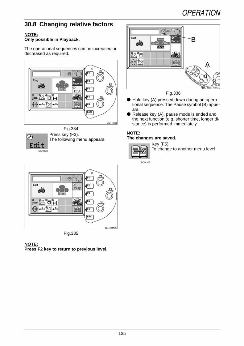
135
OPERATION30.8 Changing relative factors
NOTE:Only possible in Playback.
The operational sequences can be increased ordecreased as required.
Operation_Pic_number:1
Operation_Pic_number:1
NOTE:Press F2 key to return to previous level.
Press key (F3).The following menu appears.
Fig.334
Fig.335
Operation_Pic_number:1
● Hold key (A) pressed down during an opera-tional sequence. The Pause symbol (B) appe-ars.
● Release key (A), pause mode is ended andthe next function (e.g. shorter time, longer di-stance) is performed immediately.
NOTE:The changes are saved.
Key (F5).To change to another menu level.
Fig.336

136
OPERATION30.9 Modifying configurationlistsText-module
There are four configuration lists, which can bechanged according to the operating conditions.Text-module
Text-module
The factory settings (Fendt settings) for theconfiguration lists are:Text-module
List 1
Text-module
List 2
Text-module
List 3
Text-module
Use key (F4) to scroll through theconfiguration lists.
Function TriggerLifting gear Distance
PTO Lift heightElectric hydraulic valves DistanceVario transmission cruise
controlDistance
Four-wheel drive DistanceDifferential lock Distance
Electronic engine speed Distance
Function TriggerLifting gear Time
PTO TimeElectric hydraulic valves TimeVario transmission cruise
controlTime
Four-wheel drive TimeDifferential lock Time
Electronic engine speed Time
Function TriggerLifting gear Manual
PTO ManualElectric hydraulic valves ManualVario transmission cruise
controlManual
Four-wheel drive ManualDifferential lock Manual
Electronic engine speed Manual
List 4
Operation_Pic_number:1
Operation_Pic_number:1
Function Trigger- -- -- -- -- -- -- -
Press key (F3). The followingsubmenu appears.
Indicator showing the button on thejoystick to which the configurationlist is assigned.
Use key (F1)To change the key assignment.
Fig.337
Fig.338

137
OPERATIONText-module
Text-module
Text-module
Text-module
Use key (F2)To copy a configuration list toclipboard.For example, to save the settings ina configuration list to anotherbutton on the joystick.
Use key (F3)To copy a configuration list fromclipboard.
Use key (F4)To retrieve factory settings.
Rotary switch (P1)To select a new function.
Rotary control (P2)To select a new trigger.
Rotary switch (P3)For the configuration pair that canbe changed.
Configuration pair.
Display when there are more thanfour configuration pairs.Move up or down using rotaryswitch (P3).
Press ESC key. Following menuappears (if changes were made).
Operation_Pic_number:1
● Press key (F3) if configuration changes are tobe saved.
● Press key (F4) if the configuration changesare not to be saved.
IMPORTANT:If a configuration change is saved, the opera-tional sequence which was created with thisconfiguration list is deleted.
Fig.339

138
OPERATION30.10 Function indicator on themain menu
Operation_Pic_number:1
Text-module
Record
Playback
Initialise (prepare) the system forrecording and playback.
Edit an operating sequence.
Fault
Pause
Fig.340
30.11 Menu coloursText-module
Colours and what they signify:green = PLAY (playback of operational se-
quences).blue = RECORD (record operating sequen-
ces).yellow = EDIT (edit operating sequences).red = Fault or error message.
30.12 Messages for informationText-module
If the automatic modes for the power lift andPTO are not selected with the Variotronic TIfunction (see OPERATION Section 14), the follo-wing information appears on the multiple display.Power lift and PTO cannot be operated with theVariotronic TI function.
Operation_Pic_number:1
Power lift and/or rear PTO selected.Operation_Pic_number:1
Power lift and/or front PTO selected.
Fig.341
Fig.342

139
CARE AND MAINTENANCE
1. General
Text-module
IMPORTANT:Thoroughly clean the tractor, particularlyconnections and components that need to beopened, as well as the surrounding areas,before performing any maintenance work.Used oils, cooling- and brake fluids must bedisposed as per national laws. Dispose pro-perly according to local environmental regu-lation and to manufacturer's instructions anyused lubricant.
Oil level checks must be conducted when thetractor is horizontal and stationary; if fitted,front axle suspension should be in centre po-sition.
For maintenance intervals, checks to be per-formed, quantity and quality of lubricants tobe used, refer to Fluids and lubricants orMaintenance schedule.
NOTE:Picture catalogues of spare parts are availa-ble on the internet at the following address.www.fendt.com- language- service- spare parts catalogue
WARNING:Before any maintenance or repairwork and before opening the bonnet,switch off the engine and remove theignition key. Apply the hand brakeand chock the wheels if necessary.When working on the engine,disconnect the battery at thenegative terminal.When the maintenance work iscompleted, replace all protectiveand safety devices. Ensure that thetractor is securely parked.Ensure that the correct grades offuel and lubricants are used, andstore these in approved containersonly. See also TECHNICAL DATAFluids and Lubricants.Do not perform any welding, drilling,cutting or grinding on the cab orsafety frame. All damaged partsmust be replaced!
2. Opening the bonnetOperation_Pic_number:1
● Release lock (A).● Use the handle (B) to raise the bonnet.
NOTE:Swing the bonnet closed with a bit of power.
Fig.1

140
CARE AND MAINTENANCE
3. Engine oil changeText-module
IMPORTANT:Engine oil should also be changed prior tolong periods of immobilisation.
3.1 Draining engine oil
Operation_Pic_number:1
● Warm up the engine.
Oil temperature about 80 °C.
● Tractor must be on level ground.● Turn off the engine.● Place a collecting pan underneath the engine.● Unscrew and remove both drain plugs (A).● Drain the used oil completely.● Clean the drain plug and re-insert with a new
seal.
WARNING:Take care when draining hot oil riskof burns!Collect used oil - do not let it seepinto the ground.Dispose of used oil properly.
Fig.2
3.2 Replacing the engine oil fil-ter
Operation_Pic_number:1
Replace the oil filter (A) with every oil change.Operation_Pic_number:1
● Turn off the engine.● Clean away any dirt from the sealing surface
of the filter support.● Place oil collecting pan under the filter, uns-
crew the filter cover (A) and remove the filterelement (B).
● Check the O-ring of cap and threaded rod,and replace if necessary. Clean cover and fil-ter bowl.
● Fit new filter element (B).● Install filter cap (A) and tighten to 25 Nm.
NOTE:Used oil filters are hazardous waste.
DANGER:The oil filter may be filled with hot oil- risk of scalding and burn injuries!
Fig.3
Fig.4
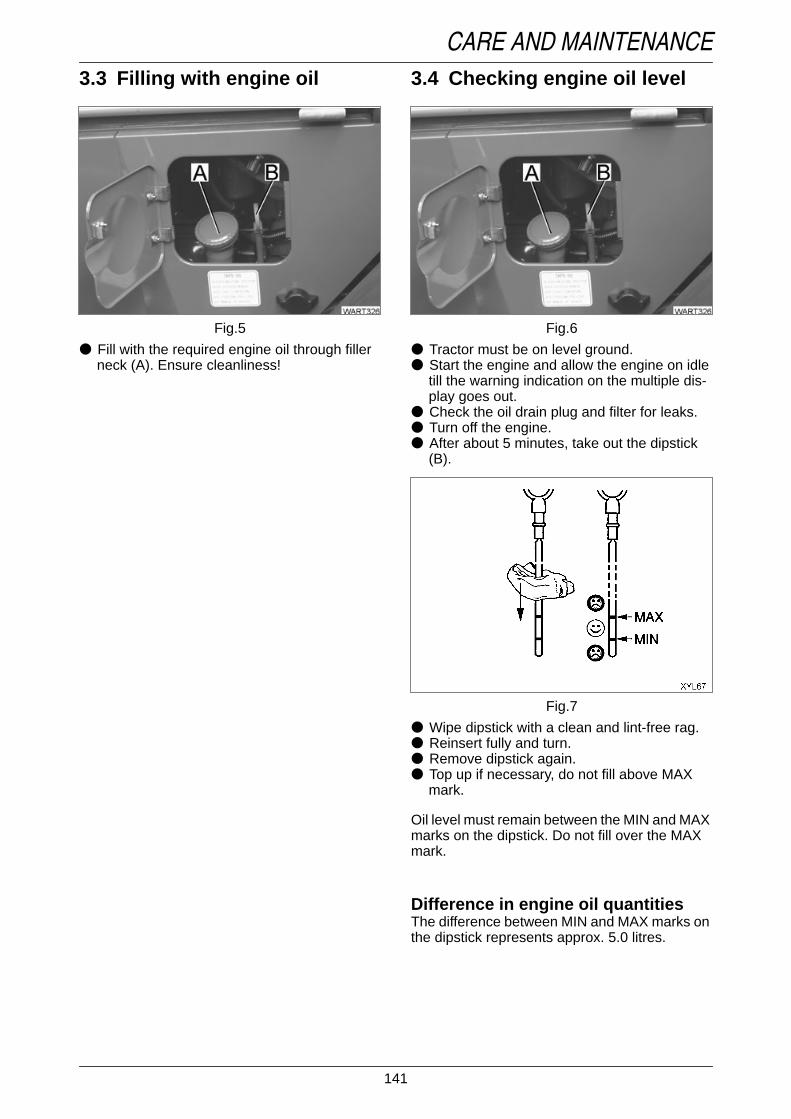
141
CARE AND MAINTENANCE3.3 Filling with engine oil
Operation_Pic_number:1
● Fill with the required engine oil through fillerneck (A). Ensure cleanliness!
Fig.5
3.4 Checking engine oil levelOperation_Pic_number:1
● Tractor must be on level ground.● Start the engine and allow the engine on idle
till the warning indication on the multiple dis-play goes out.
● Check the oil drain plug and filter for leaks.● Turn off the engine.● After about 5 minutes, take out the dipstick
(B).Operation_Pic_number:1
● Wipe dipstick with a clean and lint-free rag.● Reinsert fully and turn.● Remove dipstick again.● Top up if necessary, do not fill above MAX
mark.
Oil level must remain between the MIN and MAXmarks on the dipstick. Do not fill over the MAXmark.
Text-module
Difference in engine oil quantitiesThe difference between MIN and MAX marks onthe dipstick represents approx. 5.0 litres.
Fig.6
Fig.7

142
CARE AND MAINTENANCE
4. Fuel system
4.1 Replacing the fuel filterReplacement and maintenance as indicated inthe maintenance schedule, or sooner if engineperformance begins to fall.
Fuel filterOperation_Pic_number:1
● Turn off the engine.● Unscrew the filter cartridge (A).● Collect any escaping fuel.● Clean away any dirt from the sealing surface
of the filter support.● Lightly oil the oil seals or spray with diesel.● Tighten the filter cartridge by hand until the
seal is in contact.● Tighten the housing cover by another half
turn (to 25 Nm).● Start engine. Check for leaks.
NOTE:Used fuel filters should be treated as specialwaste.
DANGER:Never allow naked flames whenworking on the fuel system.Do not smoke.
Fig.8
Fuel filter - manual displacementpump
Operation_Pic_number:1
● Turn off the engine.● Unscrew the housing cover.● Collect any escaping fuel.● Clean away any dirt from the sealing surface
of the filter support.● Change the filter element.● Lightly oil the oil seal or spray with diesel.● Tighten the housing cover.● Start engine.● Check for leaks.
Fig.9

143
CARE AND MAINTENANCE4.2 Bleeding the fuel system
Operation_Pic_number:1
● Pull out manual pump plunger (arrowed),then push in until fuel is delivered, then givethe pump about 30-50 strokes.
● Start engine.
NOTE:If bleeding, do not open any fuel injection li-nes, the fuel injection lines will have to be re-placed.
Fig.10
4.3 Fuel prefilterText-module
(optional).
To drain water and dirtOperation_Pic_number:1
● Turn off the engine.● Open the ventilation screw (A).● To open drain plug (B), press and turn.● Drain water and contamination. Catch it with
an appropriate drip tray and dispose of it in anenvironmentally friendly manner.
● Close the ventilation screw (A).● Close drain plug (B).● Start engine. Check fuel prefilter for leaks.
Changing the filter(as required, when engine output starts to fall).
Operation_Pic_number:1
● Turn off the engine.● Unclamp the fuel supply line.● Unscrew the filter cover (A).● Remove spring housing (B).● Take out filter (C). Insert new filter.● Insert spring housing (B).● Tighten the filter cover (A).● Start engine. Check fuel prefilter for leaks.
Fig.11
Fig.12

144
CARE AND MAINTENANCE
5. Dry air filter
5.1 Vacuum checkOperation_Pic_number:1
Function check:● Remove cable connector (A) from vacuum
switch and connect to ground.● Turn ignition key to position I.
Operation_Pic_number:1
The vacuum check symbol should now appearon the multiple display, accompanied by anintermittent audible signal and a flashingwarning light.● Check air filter intake hoses and intake sy-
stem for leaks, and tighten the connections ifnecessary.
Fig.13
Fig.14
5.2 Removing/installing themain cartridge
Operation_Pic_number:1
● Undo fastners (A) and remove the cover.Operation_Pic_number:1
● Pull out main cartridge (A).● Clean filter housing; ensure sealing faces are
free of defects.● Insert main cartridge and attach the cover.
NOTE:The main cartridge must be replaced after 5cleanings, or after 2 years at the latest.
Fig.15
Fig.16

145
CARE AND MAINTENANCE5.3 Cleaning the main cartridge
Operation_Pic_number:1
Provisional cleaning by tapping:● Tap the cartridge with the heel of the palm
only.
Cleaning by blowing out:● Blow out the filter from the inside out, with dry
compressed air (maximum 5 bar, at a mini-mum distance of about 5 cm).
● Carefully blow the air through the inside of thecartridge.
NOTE:Check the filter cartridge is in perfect condi-tion after every cleaning.external damage, leaks, damaged paper bel-lows (light shine from the inside).
5.4 Replacing safety cartridgeOnly replace after the main cartridge has beenchanged 3 times, or if the main cartridge is da-maged.
Operation_Pic_number:1
● Pull out safety cartridge.● Ensure cleanliness! The clean air duct must
be kept free of dust particles.
Fig.17
Fig.18
6. Cooling system
6.1 Cleaning the cooling sy-stem
Cleaning the radiatorThe fins on the radiator, hydraulic oil cooler, fuelcooler, transmission oil cooler and airconditioning system (if installed), should be keptclean. The same applies to protective grille, andfront and side grilles.
Operation_Pic_number:1
● Open front bonnet.● Tilt air conditioner condenser up and lock in
this position.● Remove metal panel (A).● Carry out the cleaning from the engine side
using a long-handled brush or compressedair.
● For stubborn dirt, pre-clean with a soft brushusing a suitable cleaning solution (e.g. 'P3').Leave to soak for about 5 minutes then rinsewith a gentle water spray.
Cleaning the viscous fanOperation_Pic_number:1
● Keep the fins of the viscous fan (arrowed)clean.
● Do not cover radiator, otherwise the fan wouldwill not cut in.
Fig.19
Fig.20

146
CARE AND MAINTENANCE6.2 Checking the coolant level
Operation_Pic_number:1
Level between MIN and MAX mark on theexpansion reservoir.
Operation_Pic_number:1
● Only top up with clean, calcium-free waterwith antifreeze (glycol) through filler necks(A).
Check concentration of coolant. Check for even-tual leaks on hose connections (heating systemtoo!).
NOTE:The antifreeze solution also contains inhibi-tors to protect against cavitation and corro-sion. A minimum concentration of35 - 50 vol. % antifreeze and anticorrosive istherefore necessary throughout the year,even in frost-free areas.
CAUTION:When the engine is hot, take extremecare when removing the radiator capand left hot steam escape.The coolant is under pressure - riskof scalding.
Fig.21
Fig.22
6.3 Replacing coolant
Replace coolant at least every 2 years.
Draining coolant from the radiatorOperation_Pic_number:1
● Open the cap on filler neck.● Switch on the heater.● Position drain pan under engine.● Unscrew screw (A) and remove and allow
coolant to run out.Text-module
Filling with coolant● Mix antifreeze solution with clean, deminerali-
sed water and fill to the level of in the expan-sion tank.
● With the heater switched on, run the enginefor about 10 minutes (at about 1,500 rpm).
● When the engine has cooled down, check thecoolant level and top up if necessary.
6.4 Cleaning the cooling/hea-ting systemIf the coolant is badly contaminated, i. e. withrust or grease, use only hot cleaning solution(e.g. 'P3') to flush the cooling system.● Run the engine for about one hour, filled with
the cleaning solution.● Flush out with clean water and top up with
coolant solution.
DANGER:Turn off the engine!
Fig.23

147
CARE AND MAINTENANCE
7. V belt
7.1 Right hand V beltOperation_Pic_number:1
The poly-V-belt (A) has an automatic belttensioner.● Check for cracks, oil fouling, signs of over-
heating and wear.● Replace damaged belts.
The tension pulley must be replaced every timethe V ribbed belt needs to be replaced.
Air conditioning compressor V-belts (see CAREAND MAINTENANCE Section 17.2).
DANGER:Check the V-belt tensioner only withthe engine stopped! Mount theprotective grille again.
Fig.24
Setting V-belt belt tightenerOperation_Pic_number:1
● Setting as delivered of distance between cen-tres A = 92 mm.
● Re-adjustment with max. distanceA = 100 mm to A = 92 mm.
● If the distance reaches A = 100 mm again,then replace power belt.
NOTE:A gap between lugs (dimension A) of morethan 100 mm can lead to total failure of thebelt drive due to insufficient belt tension.
7.2 Left V-beltOperation_Pic_number:1
V-belt tension is to be measured at the centrepoint between pulleys, using Optibelt tensiongauge I.● Loosen alternator nut (A).● Adjustment with clamping screw (B).
Strand pull (operating tension)450+50 N (45+5 kp).
Fig.25
Fig.26

148
CARE AND MAINTENANCE
8. Brake and clutch sy-stem
Reservoir in the steering columnOperation_Pic_number:1
● Fill up the reservoir (arrowed) to 'MAX' usingonly hydraulic oil Pentosin CHF 11S.
DANGER:The brake system should bechecked thoroughly at regularintervals.Brake system adjustment and repairoperations should be performed byspecialised workshops orauthorised brake services!If there is continuous loss ofhydraulic oil from the brake andclutch system, contact the ServiceWorkshop.
Fig.27
Oil level switchOperation_Pic_number:1
Function check:● Unscrew and remove the cover.● Bring float (arrowed) to lowest position.● Turn ignition key to position 'I'.
Operation_Pic_number:1
The 'brake fluid level' symbol must appear on themultiple display, with intermittent audible signaland warning lamp flashing.
NOTE:The clutch and brake system is maintenance-free!
Fig.28
Fig.29

149
CARE AND MAINTENANCE
9. Front PTO
Front PTO oil levelOperation_Pic_number:1
● Fill oil through filler hole (A).● Oil drain screw (B).
Oil level: fill up to overflow at filler hole (A).
Fig.30
10. Transmission andaxle drives
10.1 Changing the transmis-sion oilChange the oil only when the transmission oil iswarm.
Draining the transmission oilOperation_Pic_number:1
● Place oil drip pan underneath the transmis-sion.
● Unscrew drain plug (A), remove and allow oilto drain completely.
● Clean the drain plug, refit and tighten.Operation_Pic_number:1
● Unscrew drain plugs (A) on either side of thebrake housing and allow oil to drain comple-tely.
● Clean the drain plugs, re-insert and tighten.
Fig.31
Fig.32

150
CARE AND MAINTENANCEReplacing pressure filterA soiled pressure filter (A) is indicated by awarning message (see also FAULTS ANDREMEDIAL ACTIONS Section 1.1). Replace thefilter element as soon as possible, but not laterthan every 1000 operating hours.
Operation_Pic_number:1
Text-module
● Unscrew the filter housing (A).● Withdraw the filter element from housing.● Replace the filter element, do not wash out.● Lightly oil the sealing rings.● Put filter housing back in place and tighten
screw (to 40 Nm).
Replacing intake filterOperation_Pic_number:1
● Remove cover (A) and extract the intake filter.● Replace the spin-oil filter.
Fig.33
Fig.34
Filling gear oilOperation_Pic_number:1
● Remove dipstick (A) and pour oil through thefiller hole.
10.2 Checking the transmissionoil level● Tractor must be on level ground.● Twist the dipstick and pull out.● Wipe the dipstick using a clean, fibre-free rag.● Reinsert dipstick fully and twist into place.● Twist the dipstick and remove again.
The oil level must reach the upper notch on thedipstick.
Difference in oil volume between min. and max.marks on dipstick is approx. 3 litres.
Fig.35

151
CARE AND MAINTENANCE10.3 Changing the oil in the axledrives
Operation_Pic_number:1
● Place an oil drip pan underneath the trans-mission.
● Unscrew drain plug (A), remove and allow oilto drain completely.
● Clean the drain plugs, re-insert and tighten.● Pour in the required oil through filler hole (B)
on the left and the right axle carrier.
Oil level must be up to overflow at filler hole (B).
Fig.36
11. Four-wheel driveaxle
11.1 Changing the oil in thefront axle differential gear
Draining the oilOperation_Pic_number:1
● Place an oil drip pan underneath the trans-mission.
● Unscrew drain plug (A), remove and allow oilto drain completely.
● Clean the drain plug, refit and tighten.
Filling with oilOperation_Pic_number:1
● Pour in the required oil through filler hole (A).
Oil level must reach the overflow at filler hole (A).
Fig.37
Fig.38

152
CARE AND MAINTENANCE11.2 Replacing the oil in frontaxle hub drives
Operation_Pic_number:1
To change the oil, jack up front axle until wheelsrotate freely; disengage the 4WD.
Draining the oil● Turn wheel until the hole is at the bottom.● Place collecting pan underneath.● Remove drain plug and allow the oil to drain
completely.● Clean the drain plug, refit and tighten.
Filling with oil● With hole on the left and marker in horizontal
position, fill with oil up to the overlow.
Fig.39
11.3 Front axle suspension
Relieving pressure from hydraulic li-nes
Operation_Pic_number:1
● Remove cover plates from right of doorway.● Open plugs (A).
WARNING:Even with the engine switched offand the load removed from the frontaxle, hydraulic lines of the frontsuspension are under pressure.Always relieve pressure beforeundoing connections!When checking for leaks, to avoidinjury, use suitable material (e.g. apiece of wood).
Fig.40

153
CARE AND MAINTENANCE
12. Power lift
Checking oil level in power liftOperation_Pic_number:1
● Unscrew plug (A).● Check oil level with a test strip (e. g. cable
tie).
The oil level must be approx. 40 mm (vertically)below the bottom edge of the filler hole.
Fig.41
13. Hydraulic system
13.1 Checking oil level in hyr-draulic system
Operation_Pic_number:1
The level (A) in the hydraulic oil reservoir oil levelis shown on the dashboard. When filling with oilto MAX, the rear power lift must be lowered andall cylinders retracted.
DANGER:When working on the hydraulics,always switch off the engine andensure that the tractor is safelyparked (hand brake applied, wheelschocked).The system is under high pressure.Ensure that all pressure is released,and that mounted implements arelowered before any work is carriedout on the hydraulics.When checking for leaks, to avoidinjury, use suitable material (e.g. apiece of wood).Regularly check hydraulic hoses,and replace if they show signs ofdamage or ageing! Replacementhoses must meet the technicalrequirements of the implementmanufacturer!Always ensure the utmostcleanliness when working onhydraulic components.
Fig.42
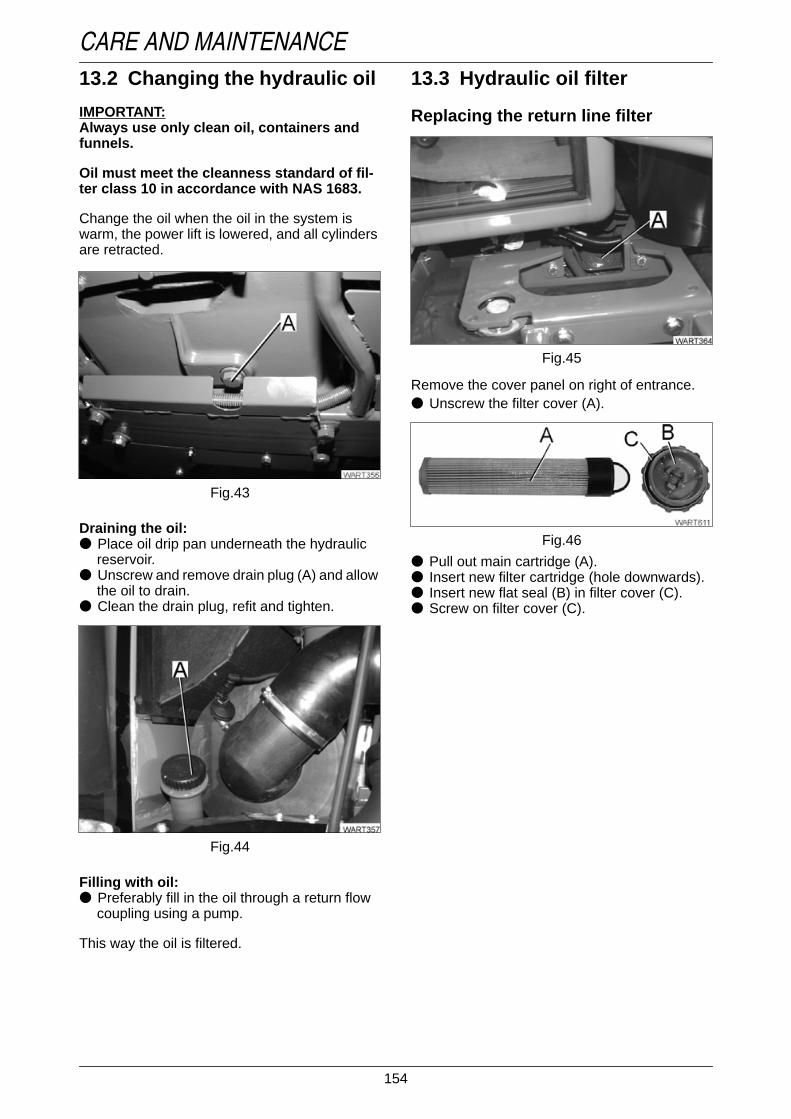
154
CARE AND MAINTENANCE13.2 Changing the hydraulic oil
IMPORTANT:Always use only clean oil, containers andfunnels.
Oil must meet the cleanness standard of fil-ter class 10 in accordance with NAS 1683.
Change the oil when the oil in the system iswarm, the power lift is lowered, and all cylindersare retracted.
Operation_Pic_number:1
Draining the oil:● Place oil drip pan underneath the hydraulic
reservoir.● Unscrew and remove drain plug (A) and allow
the oil to drain.● Clean the drain plug, refit and tighten.
Operation_Pic_number:1
Filling with oil:● Preferably fill in the oil through a return flow
coupling using a pump.
This way the oil is filtered.
Fig.43
Fig.44
13.3 Hydraulic oil filter
Replacing the return line filterOperation_Pic_number:1
Remove the cover panel on right of entrance.● Unscrew the filter cover (A).
Operation_Pic_number:1
● Pull out main cartridge (A).● Insert new filter cartridge (hole downwards).● Insert new flat seal (B) in filter cover (C).● Screw on filter cover (C).
Fig.45
Fig.46

155
CARE AND MAINTENANCEReplacing air vent filter
Operation_Pic_number:1
● Unscrew and remove air vent filter (A) andscrew in a new filter.
NOTE:The vent filter cannot be cleaned.
Replacing the control pressure finefilter
Operation_Pic_number:1
● Unscrew the threaded connection (A) on thevalve end plate.
Fig.47
Fig.48
Operation_Pic_number:1
● Change the fine filter (A).● Screw in the threaded connection (see CARE
AND MAINTENANCE Fig. 48 /A) and tightento 5.5 +1.8 Nm.
NOTE:Ensure the utmost cleanliness when cleaningthe fine filter.Minute particles of dirt in the control circuitcan affect the functioning of the work hydrau-lics.
Fig.49

156
CARE AND MAINTENANCETemperature warning device
Operation_Pic_number:1
If oil temperature is too high, this is indicated bya warning message, (see also FAULTS ANDREMEDIAL ACTIONS Section 1.1).
Function check:● Detach cable connector (A) from the tempe-
rature switch and connect to ground.● Turn ignition key to position 'I'.
Operation_Pic_number:1
'Hydraulic oil temperature' symbol is shown onmultiple display, with warning lamp flashing andintermittent tone.
14. SteeringRegularly check the steering for leaks and signsof damage, check that the sealing bellows are ingood condition, and check the hoses for chafingmarks.
Fig.50
Fig.51
15. Front wheels
15.1 Checking toe-inAfter initial 50 operating hours, then every 500operating hours.
Operation_Pic_number:1
Toe-in should be 0 - ±1 mm.● Steering straight ahead; Average axle load.● Measure distance between tyres on the
wheel hub at the front rim flange (A).● Push tractor forward by 1/2 turn of the front
wheels.● Measure distance between tyres on the
wheel hub at the rear rim flange (B).
Fig.52
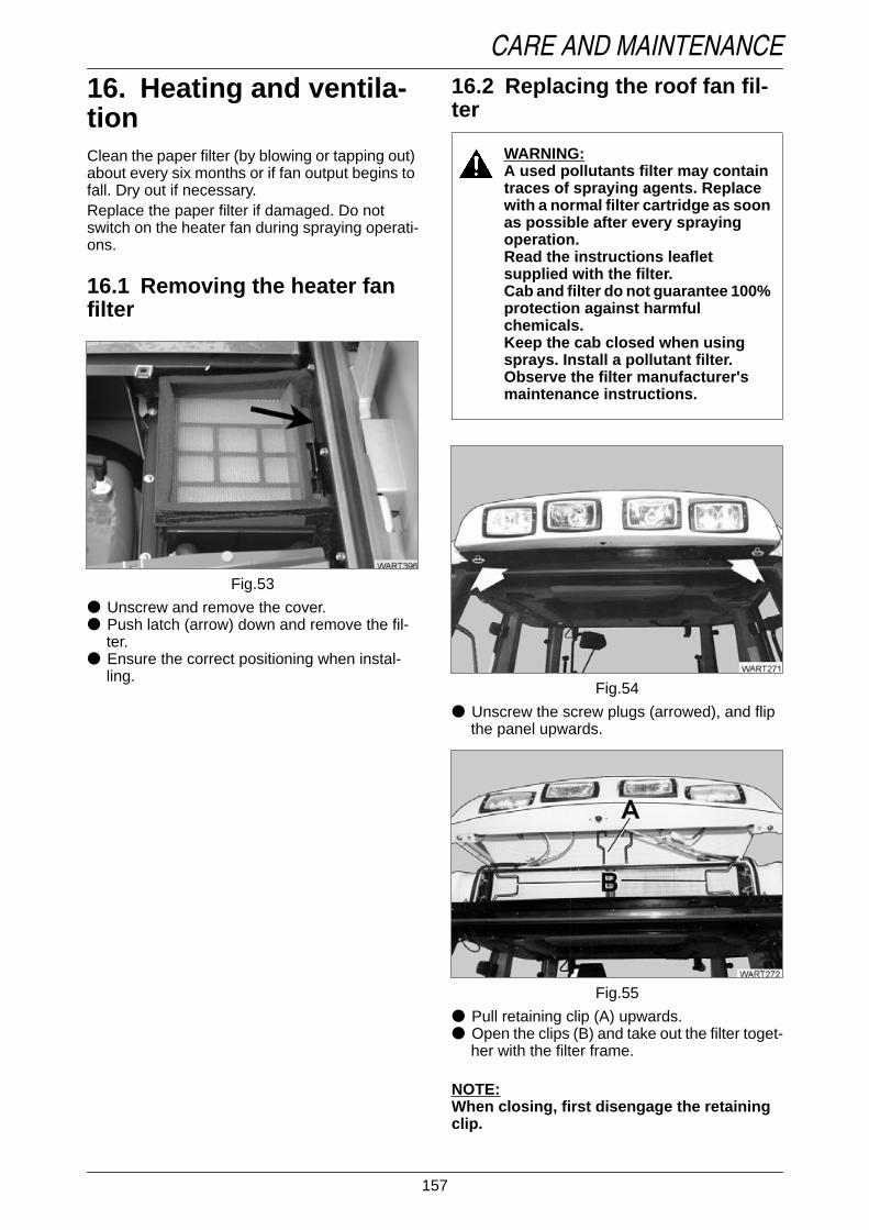
157
CARE AND MAINTENANCE
16. Heating and ventila-tionClean the paper filter (by blowing or tapping out)about every six months or if fan output begins tofall. Dry out if necessary.Replace the paper filter if damaged. Do notswitch on the heater fan during spraying operati-ons.
16.1 Removing the heater fanfilter
Operation_Pic_number:1
● Unscrew and remove the cover.● Push latch (arrow) down and remove the fil-
ter.● Ensure the correct positioning when instal-
ling.
Fig.53
16.2 Replacing the roof fan fil-ter
Text-moduleOperation_Pic_number:1
● Unscrew the screw plugs (arrowed), and flipthe panel upwards.
Operation_Pic_number:1
● Pull retaining clip (A) upwards.● Open the clips (B) and take out the filter toget-
her with the filter frame.Text-module
NOTE:When closing, first disengage the retainingclip.
WARNING:A used pollutants filter may containtraces of spraying agents. Replacewith a normal filter cartridge as soonas possible after every sprayingoperation.Read the instructions leafletsupplied with the filter.Cab and filter do not guarantee 100%protection against harmfulchemicals.Keep the cab closed when usingsprays. Install a pollutant filter.Observe the filter manufacturer'smaintenance instructions.
Fig.54
Fig.55

158
CARE AND MAINTENANCE16.3 Replacing the recirculatingair filter
Operation_Pic_number:1
● Dismount air nozzles (right and left) and re-move filter (A).
Fig.56
17. Air conditioningText-module
Switch on the air conditioning once a month(even in winter) for about 10 minutes, setting theventilation to recirculated air mode (see OPERA-TION Section 3.2).Clean roof fan filter and recirculating air filter(see CARE AND MAINTENANCE Section 16).
17.1 CondenserOperation_Pic_number:1
● If dirty, blow through or spray the condenser(A) from the inside.
Checking coolant levelOperation_Pic_number:1
● Switch on system. The compressor must alsobe running. At an engine speed of 2,000 rpm;white ball (A) in the sight glass of the fluid tankmust float.
Topping up with coolant or replacing the tank /dryer can only be undertaken in the workshop.
NOTE:The blue ball turning pink indicates moisturein the system.
Fig.57
Fig.58
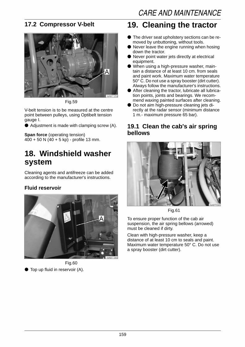
159
CARE AND MAINTENANCE17.2 Compressor V-belt
Operation_Pic_number:1
V-belt tension is to be measured at the centrepoint between pulleys, using Optibelt tensiongauge I.● Adjustment is made with clamping screw (A).
Span force (operating tension)400 + 50 N (40 + 5 kp) - profile 13 mm.
18. Windshield washersystemCleaning agents and antifreeze can be addedaccording to the manufacturer's instructions.
Fluid reservoirOperation_Pic_number:1
● Top up fluid in reservoir (A).
Fig.59
Fig.60
19. Cleaning the tractorText-module
● The driver seat upholstery sections can be re-moved by unbuttoning, without tools.
● Never leave the engine running when hosingdown the tractor.
● Never point water jets directly at electricalequipment.
● When using a high-pressure washer, main-tain a distance of at least 10 cm. from sealsand paint work. Maximum water temperature50° C. Do not use a spray booster (dirt cutter).Always follow the manufacturer's instructions.
● After cleaning the tractor, lubricate all lubrica-tion points, joints and bearings. We recom-mend waxing painted surfaces after cleaning.
● Do not aim high-pressure cleaning jets di-rectly at the radar sensor (minimum distance1 m.- maximum pressure 65 bar).
19.1 Clean the cab's air springbellows
Operation_Pic_number:1
To ensure proper function of the cab airsuspension, the air spring bellows (arrowed)must be cleaned if dirty.
Clean with high-pressure washer, keep adistance of at least 10 cm to seals and paint.Maximum water temperature 50° C. Do not usea spray booster (dirt cutter).
Fig.61

160
CARE AND MAINTENANCE
20. Electrical and elec-tronic systemsSince even a test lamp can damage electroniccomponents in the electrical system, troubleshooting must always be carried out in the work-shop.Disconnect battery if the tractor is not used forlong periods, to prevent it being discharged bysmall consumers. Check the battery charge levelevery 2 months. Do not operate the tractor wit-hout a battery.Text-module
In the following conditions, stored settings (forexample, the speed indicator setting) are lostand are replaced by the default values:
ETNum-list
20.1 Battery
Operation_Pic_number:1
Acid level approx. 15 mm above the top of theplates.● Top up with distilled water when necessary.
Not necessary with sealed batteries. Keep bat-tery clean!
Keep battery in good charging condition - espe-cially in cold weather.
Do not operate the tractor without a battery.
1.Drained or disconnected battery.2.White connector 1 disconnected from
instrument cluster.
WARNING:When working on the electricalsystem, always disconnect thebattery (negative terminal).Use the correct connectingsequence - connect first plusterminal and then minus terminal.Beware of battery acid caustic!Beware of battery gases!Avoid sparks and naked flame nearthe battery. The glass on work lampsare very hot while switched on!
Fig.62
20.2 AlternatorCharge control lamps go out after starting at ap-prox. 1,000 rpm.
20.3 ElectroweldingDisconnect both battery terminals. Keep groundterminal as close to the point of welding as pos-sible; be aware of components sensitive to tem-perature.
20.4 Adjusting the headlights
Operation_Pic_number:1
● Adjust headlights using the Phillips screws(arrows).
CAUTION:Before adjusting, bring the tractorfront axle suspension to centreposition of the total suspensionrange (see also OPERATIONSection 13).
Fig.63

161
CARE AND MAINTENANCE20.5 Adjusting the auxiliaryheadlampss
Operation_Pic_number:1
At a 10 metre distance the upper limit of theilluminated area is two thirds of the height of thetractor lights.
20.6 Auxiliary lights, Xenonheadlights
Text-module
Xenon headlightsOperation_Pic_number:1
Text-module
To be remembered when operating the head-lamps.● Headlamps develop a lot of heat. Fire hazard.● Do not look directly into the light.● Clean the glass from time to time, but only
when they are cold.● Do not clean the glass with fluid when the
lamps are on. Danger of shattering!
DANGER:Always pull out connector (A/ CAREAND MAINTENANCE Fig. 65) whencarrying out maintenance and repairwork.
Fig.64
Fig.65
● Do not use aggressive or abrasive cleaningagents.
● Do not operate on public roads.Text-module
To be remembered when replacing the bulb.● Always turn off the headlamps and discon-
nect the supply voltage before changing thebulb.
● Do not reach into the bulb socket.● The connection between headlamp and con-
nection unit carries high voltage. Do not dis-connect!
● Do not operate transformer unit without abulb. Flashovers at the bulb socket can causedamage.
● Allow bulb to cool.● When changing the bulb, wear safety glasses
and gloves.● The glass body of the bulb is under pressure.
Danger of splitters!● Only touch bulb at the base.● Remove dirt from the glass with alcohol and a
clean cloth.● Only use the bulb in a sealed headlamp.● If the bulb breaks in a closed room, the room
must be cleared of people and aired for at le-ast 20 minutes to avoid health hazards due tothe gases.
● Dispose of faulty bulbs as special waste.

162
CARE AND MAINTENANCE20.7 Additional installation of electrical and electronic equipmentSafety recommendations for subsequent fitting of electrical and electronic equipment and/orcomponents.Text-module
The tractor is equipped with electronic components whose functions can be influenced by electroma-gnetic signals from other units. This may constitute a danger - follow the safety instructions below, toavoid injuries.When installing additional electrical and electronic equipment and/or components in the machine, andconnecting them to the on-board electrical system, it is the user's responsibility to check for possibleinterference with the tractor electronic system. This is particularly important for:
Connection of consumers.● Never connect any equipment to sensing components (sensors) since this may interfere with con-
trol functions (EPC, comfort control, etc.).
Power used by consumers.● Voltage dips or spikes may lead to spurious error messages.
Short-wave transmitters.● Transmissions without a special antenna can cause malfunctions (EPC, comfort control, etc.).
Make sure that all subsequently installed electrical and electronic components comply with the rele-vant version of EMC guideline 89/336/EEC, and that they carry the CE symbol.
Text-module
Subsequent installation of mobile communication systemsFor the subsequent installation of mobile communication systems (e.g. radio, telephone) the followingrequirements have to be met:● Only equipment complying with national regulations may be installed.● The equipment must be securely installed.● Portable or mobile equipment used within the vehicle is permissible only when connected to an ex-
ternally installed aerial.● The transmitter must be fitted well clear of the vehicle electronics.● Make sure the aerial is fitted properly with a good ground contact between aerial and vehicle body.Text-module
For cabling, installation and a maximum permissible power consumption, observe instructions ofequipment manufacturer.

163
CARE AND MAINTENANCE
21. Fuses
DANGER:Use only original fuses. Excess amperage fuses can destroy the electrical system. Firehazard.
Fuse holder (X050, X051, F060-F067)Operation_Pic_number:1
● Unlatch (arrow) and remove document box.Operation_Pic_number:1
Fuse holder (X050, X051, F060-F067)
Fig.66
Fig.67
Fuse holder (A013)Operation_Pic_number:1
● Unscrew trim panel (arrowed).Operation_Pic_number:1
Fuse holder (A013).
Starter relay fuse (A) 24 VOperation_Pic_number:1
Fig.68
Fig.69
Fig.70

164
CARE AND MAINTENANCE21.1 Fuse holder X050
Operation_Pic_number:1
Text-module
Fuse no. PIN Amps(A)
Consumers
1 - - -2 30 25 Glow and starter switch in ON position3 30 5 Joystick4 30 5 Relay EPC Ub5 30 25 LBS implement socket CAN bus connection6 30 15 Hazard warning light pushbutton7 30 15 Driving lamps pushbutton8 30 10 Radio, cab interior lighting9 30 15 Relay no. 56a (high beam)
10 30 15 Relay no. 56b (low beam)11 30 25 Socket 25 A12 30 10 10 A socket13 15 10 Flame starting system14 15 15 Heater switch15 15 15 Hazard warning light pushbutton16 15 5 Driving lamps pushbutton17 15 40 Blower switch18 15 15 Front screen wipers controller19 15 10 Starter lockout switch, emergency operation relay20 15 10 Steering column switch (combination switch)21 15 15 Driver seat, heated seat22 15 10 Engine brake23 15 15 Brake relay24 15 10 Hydraulic circuit 325 15 25 Rear window heater, mirror heater26 15 10 Socket 10 A, reverse travel warning beep27 15 10 LBS implement socket28 50 40 Flame starting device in Start position29 15 25 Not allocated
Fig.71

165
CARE AND MAINTENANCE21.2 Fuse holder X051
Operation_Pic_number:1
Text-module
Fuse no. PIN Amps(A)
Consumers
31 58 25 Rear socket 20 amps32 58 5 Instrument panel33 58 25 Front work lamps switch34 58 40 Front work lamps switch35 58 25 Rear work lamps switch36 58 25 Rear work lamps switch37 58 5 Rear right tail light, right marker light38 58 5 Rear left tail light, left marker light39 30E 10 Terminal, communications box power supply40 30E 5 Instrument panel41 30E 40 E-box comfort42 30E 10 Operating console43 30E 15 Actuator control44 15 E 5 Operating console45 15 E 5 E-box comfort46 15 E 5 Vario Terminal47 15 E 5 Joystick48 15 E 15 EHR, OBE49 15 E 5 Instrument panel50 15/58 15 Valve heating51 15/58 5 Implement socket, communications box power supply52 54 10 Trailer socket53 R 10 Front socket for front power lift, trailer socket54 15 E 5 Test connection55 58L 10 Front socket for front power lift, trailer socket56 L 10 Front socket for front power lift, trailer socket57 58R 10 Trailer socket58 30 15 Engine control59 - - -
Fig.72

166
CARE AND MAINTENANCE21.3 Fuse holder F060 - F067
Operation_Pic_number:1
Text-module
Fuse no. Clip Amps(A)
Consumers
F060 30 25 Socket ABS PIN 1, UB30F061 15 5 Socket ABS PIN 1, UB15F062 15 5 Indicator lamp ABSF063 15 10 Power supply spool valves (SB23)F064 15 5 Radar sensorF065 30 15 JoystickF066 - - -F067 30 60 LBS-socket pin3, DIN-ISO
Fig.73

167
CARE AND MAINTENANCE21.4 Fuse holder (A013)
Operation_Pic_number:1
Text-module
Fig.74
Fuse Con-nector
Components Comp.sep.pt.
01 X200/18 - -02 X200/16 2nd high-pressure
sensorX177
03 X200/15 High pressure sen-sor
X157
04 X200/14 Engine Hall sensor 1 X15905 X200/10 - -06 X200/11 - -07 X200/12 Bevel pinion turning
angle sensorX164
08 X200/09 Clutch pedal turningangle sensor
X166
09 X201/14 - -10 X201/12 - -11 X201/11 Front power lift posi-
tion turning anglesensor
X188
12 X201/10 - -13 X200/07 Operating range re-
cognition torquesensor
X165
14 X200/08 - -15 X200/04 - -16 X200/05 Speed sensor, hy-
drostatic drive col-lector shaft
X163
17 X200/06 Accelerator pedalturning angle sensor
X176
18 X201/04 Suspension turningangle sensor
X152
19 X201/05 - -20 X201/06 - -21 X201/07 Steering angle sen-
sorX403
22 X201/08 Front PTO Hall ge-nerator
X151
23 X201/09 - -24 X201/18 Engine oil pressure
sensorX161
25 X201/16 Compressed airsensor
X168
26 X201/15 Hand throttle turningangle sensor
X183
27 X202/07 - -28 X202/06 - -29 X202/05 - -30 X202/04 - -31 X202/08 - -32 X202/09 Rear PTO Hall ge-
neratorX169
33 X202/10 Rear PTO Hall ge-nerator
X170

168
CARE AND MAINTENANCE
22. Wiring diagrams
22.1 Legend for circuit diagramsText-module
X001 to X999 are electric couplers, butt-type connectors and other connectors.
A002 = E-BoxA003 = Drive mode switchA004 = Operating consoleA005 = E-box lifting gear controlA006 = Front dashboard keyboardA007 = Instrument panelA008 = Vario TerminalA009 = Actuator controlA010 = Electronic thermostatA011 = Radar sensorA012 = Flame starting systemA013 = Fuse board ABCA015 = Radio pre-fittingA016 = Mirror heaterA017 = LBS bus termination boardA018 = TankA020 = Electronic injection pumpA021 = EDC electronics boxA023 = Front LBS bus terminalB001 = Steering angle sensor 1B002 = PTO speed Hall sensorB003 = Suspension turning angle sensorB004 = Vacuum switchB005 = Engine temperature sensorB006 = Charge air temperature sensorB007 = Fuel level sensorB008 = High pressure sensorB009 = Discharge temperature sensorB010 = Engine Hall sensor 1B012 = Engine oil pressure sensorB013 = Hydraulic oil temperature switchB014 = Speed sensor, hydrostatic drive col-
lector shaftB015 = Bevel pinion speed sensorB016 = Operating range recognition torque
sensorB017 = Clutch pedal turning angle sensorB018 = Engine rpm setpoint sensorB019 = Compressed air supply pressure
sensorB020 = Rear PTO rpm Hall sensorB021 = Rear PTO rpm after clutch sensorB022 = Kickout pressure switchB023 = Flame starting system temperature
sensorB024 = Steering angle sensor 2B025 = EDC speed sensorB026 = EDC needle motion sensorB027 = Water temperature sensorB028 = ICharge pressure sensor
B029 = Accelerator pedal turning angle sen-sor
B030 = Measured value, position sensorB031 = Right load sensor pinB032 = Load sensor pin leftB033 = Discharge temperature sensorB034 = Immersed tube sensorB035 = Hand throttle turning angle sensorB036 = Tank sensor 1B037 = Tank Sensor 2B038 = EDC accelerator angle sensorB040 = Front power lift position torque sen-
sorB041 = Temperature sensor
(Air cond. NT C2)B046 = Temperature sensor
(Air cond. NT C1)B047 = Steering angle switchB050 = Loudspeaker, leftB051 = Loudspeaker, rightE001 = H4 headlamp, rightE002 = H4 headlamp, leftE003 = H4 headlamp, rightE004 = H4 additional work lamp, leftE005 = Position lamp, front rightE006 = Position lamp, front leftE007 = Turn signal/brake/tail lamp, rightE008 = Left turn signal/brake/taillampE009 = Licence plate lamp, rightE010 = Licence plate lamp, leftE011 = Work lamp on roof, right rearE012 = Left rear roof work lampE013 = Right front roof work lampE014 = Work lamp on roof front leftE015 = Front work lamp on right turn signal
lampE016 = Front work lamp at left turn signal
lampE017 = Work lamp on taillamp holder rightE018 = Work lamp at left taillamp holderE019 = Cab lightingE020 = EPC lightingE021 = Rotating beacon, rightE022 = Rotating beacon leftE023 = Rear window heaterE024 = Right mirror heater connectionE025 = Connection, mirror heater leftE026 = Right turn signal lamp, on roof top
rearE027 = Left turn signal indicator, roof top
rear
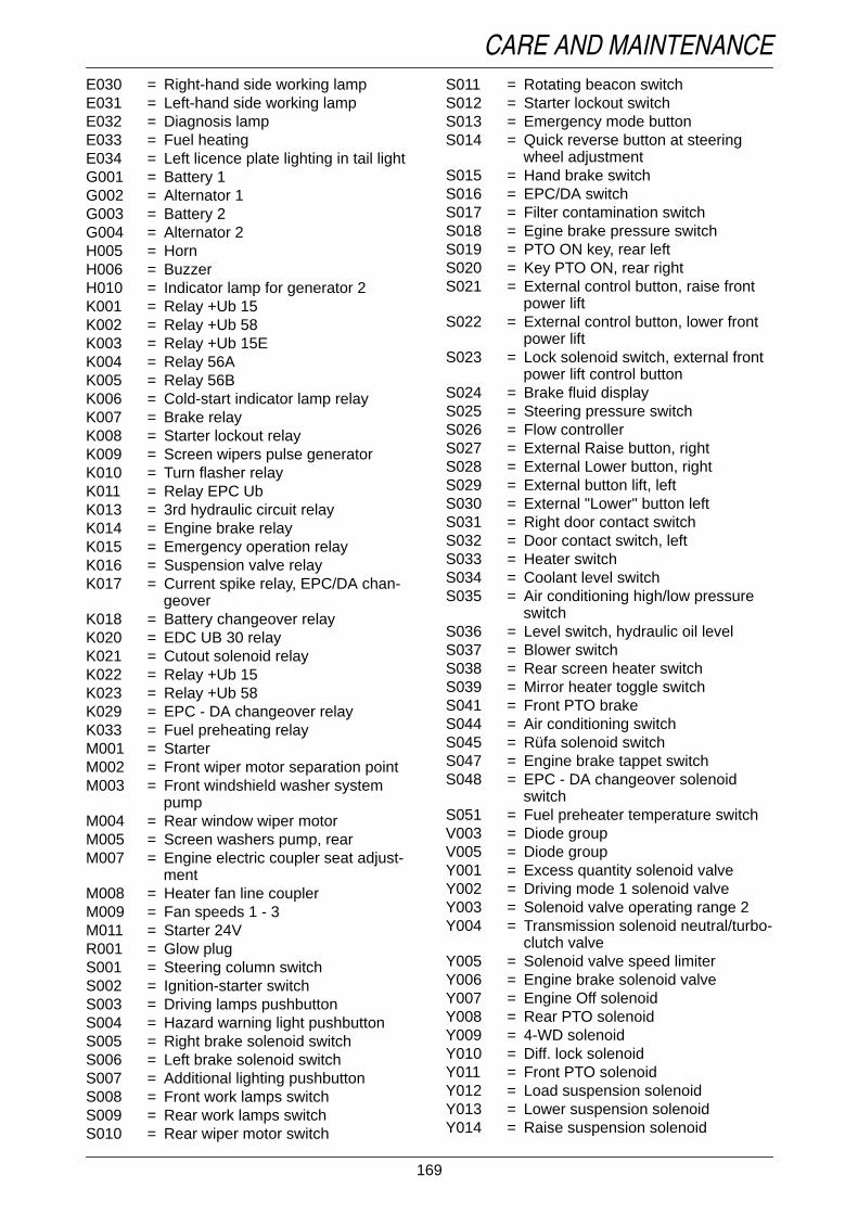
169
CARE AND MAINTENANCEE030 = Right-hand side working lampE031 = Left-hand side working lampE032 = Diagnosis lampE033 = Fuel heatingE034 = Left licence plate lighting in tail lightG001 = Battery 1G002 = Alternator 1G003 = Battery 2G004 = Alternator 2H005 = HornH006 = BuzzerH010 = Indicator lamp for generator 2K001 = Relay +Ub 15K002 = Relay +Ub 58K003 = Relay +Ub 15EK004 = Relay 56AK005 = Relay 56BK006 = Cold-start indicator lamp relayK007 = Brake relayK008 = Starter lockout relayK009 = Screen wipers pulse generatorK010 = Turn flasher relayK011 = Relay EPC UbK013 = 3rd hydraulic circuit relayK014 = Engine brake relayK015 = Emergency operation relayK016 = Suspension valve relayK017 = Current spike relay, EPC/DA chan-
geoverK018 = Battery changeover relayK020 = EDC UB 30 relayK021 = Cutout solenoid relayK022 = Relay +Ub 15K023 = Relay +Ub 58K029 = EPC - DA changeover relayK033 = Fuel preheating relayM001 = StarterM002 = Front wiper motor separation pointM003 = Front windshield washer system
pumpM004 = Rear window wiper motorM005 = Screen washers pump, rearM007 = Engine electric coupler seat adjust-
mentM008 = Heater fan line couplerM009 = Fan speeds 1 - 3M011 = Starter 24VR001 = Glow plugS001 = Steering column switchS002 = Ignition-starter switchS003 = Driving lamps pushbuttonS004 = Hazard warning light pushbuttonS005 = Right brake solenoid switchS006 = Left brake solenoid switchS007 = Additional lighting pushbuttonS008 = Front work lamps switchS009 = Rear work lamps switchS010 = Rear wiper motor switch
S011 = Rotating beacon switchS012 = Starter lockout switchS013 = Emergency mode buttonS014 = Quick reverse button at steering
wheel adjustmentS015 = Hand brake switchS016 = EPC/DA switchS017 = Filter contamination switchS018 = Egine brake pressure switchS019 = PTO ON key, rear leftS020 = Key PTO ON, rear rightS021 = External control button, raise front
power liftS022 = External control button, lower front
power liftS023 = Lock solenoid switch, external front
power lift control buttonS024 = Brake fluid displayS025 = Steering pressure switchS026 = Flow controllerS027 = External Raise button, rightS028 = External Lower button, rightS029 = External button lift, leftS030 = External "Lower" button leftS031 = Right door contact switchS032 = Door contact switch, leftS033 = Heater switchS034 = Coolant level switchS035 = Air conditioning high/low pressure
switchS036 = Level switch, hydraulic oil levelS037 = Blower switchS038 = Rear screen heater switchS039 = Mirror heater toggle switchS041 = Front PTO brakeS044 = Air conditioning switchS045 = Rüfa solenoid switchS047 = Engine brake tappet switchS048 = EPC - DA changeover solenoid
switchS051 = Fuel preheater temperature switchV003 = Diode groupV005 = Diode groupY001 = Excess quantity solenoid valveY002 = Driving mode 1 solenoid valveY003 = Solenoid valve operating range 2Y004 = Transmission solenoid neutral/turbo-
clutch valveY005 = Solenoid valve speed limiterY006 = Engine brake solenoid valveY007 = Engine Off solenoidY008 = Rear PTO solenoidY009 = 4-WD solenoidY010 = Diff. lock solenoidY011 = Front PTO solenoidY012 = Load suspension solenoidY013 = Lower suspension solenoidY014 = Raise suspension solenoid

170
CARE AND MAINTENANCEY015 = Valve 1Y016 = Valve 2Y017 = Valve 3Y018 = Valve 4Y019 = Valve 5Y021 = Raise solenoidY022 = Lower solenoid valveY023 = Compressed air pilot control sole-
noid valveY024 = Air conditioning magnetic clutchY025 = Flame starting system solenoid valveY026 = Rear PTO stage 1 solenoidY027 = Solenoid valve, rear PTO stage 2Y028 = Solenoid valve, rear PTO stage 3Y030 = EPC/DA lock solenoid valveY031 = EPC/DA pilot control solenoid valveY032 = Solenoid valve neutral (valves)Y033 = Solenoid valve, flush valvesY034 = Brake release solenoid valve

171
CARE AND MAINTENANCE22.2 Colour coding for electric wiresText-module
22.3 Wiring diagramsText-module
List of wiring diagramsSheet 2 = Power supply + UBSheet 3 = Grounding layoutSheet 4 = Starter controlSheet 5 = Cold-start systemSheet 6 = Engine brake and engine switch-off, active stationarySheet 7 = STVZO lighting Sheet 1Sheet 8 = STVZO lighting with horn Sheet 2Sheet 9 = Turn signal systemSheet 10 = Brake light, compressed air supply, hydr. trailer brake, ABS brakeSheet 11 = Wipers and rotating beaconSheet 12 = Work lamps front, EPC lightingSheet 13 = Rear work lampsSheet 14 = Cab interior lighting and radioSheet 15 = Ventilation and air conditioningSheet 16 = HeaterSheet 17 = Heated rear window, electrical mirrorsSheet 18 = Socket and open separation points, seat switchSheet 19 = Implement socket, socket event counterSheet 20 = Electronics power supplySheet 21 = Comfort bus (K bus)Sheet 22 = Instrument panelSheet 23 = Electrohydraulic lifting gear controlSheet 24 = Electro-hydraulic spool valves 1 (+UB valves, hydraulics monitoring, external valve ac-
tuation)Sheet 25 = Hydraulic valve 2 (front power lift, hydr. circuit 3, valve operation)Sheet 26 = Transmission bus (G bus)Sheet 27 = Transmission controlSheet 28 = Transmission emergency operationSheet 29 = SuspensionSheet 30 = PTOSheet 31 = 4WD and differential lockSheet 32 = LBS (Agricultural BUS system)Sheet 33 = Engine control
Colour of wire Abbreviation Markwhite (with black printing) ws General colour of wiresred rt + UB 30black sw + UB 15yellow ge + UB 15Egrey (basic colour for lighting) gr + UB 58grey - black gr-sw + UB 58 lighting leftgrey - red gr-rt + UB 58 lighting rightyellow ge + UB power supplybrown br vehicle body groundbrown - white br-ws Electronics groundbrown - yellow br-ge Sensors groundblack - green sw-gn Right side turn signal lampblack - white sw-ws Left side turn signal lamporange or Additional wiringblue blpink rsturquoise tkviolet vi

172
CAR
E AND
MAIN
TENAN
CE
ET
Wiring-diagram
22.3 Power supply + UB930.900.000.004 Sheet 2

173
CAR
E AND
MAIN
TENAN
CE
ET
Wiring-diagram
22.4 Grounding layout930.900.000.004 Sheet 3

174
CAR
E AND
MAIN
TENAN
CE
ET
Wiring-diagram
22.5 Starter control930.900.000.004 Sheet 4

175
CAR
E AND
MAIN
TENAN
CE
ET
Wiring-diagram
22.6 Cold-start system930.900.000.004 Sheet 5

176
CAR
E AND
MAIN
TENAN
CE
ET
Wiring-diagram
22.7 Engine brake and engine switch-off,active stationary930.900.000.004 Sheet 6

177
CAR
E AND
MAIN
TENAN
CE
ET
Wiring-diagram
22.8 STVZO lighting Sheet 1930.900.000.004 Sheet 7

178
CAR
E AND
MAIN
TENAN
CE
ET
Wiring-diagram
22.9 STVZO lighting with horn Sheet 2930.900.000.004 Sheet 8

179
CAR
E AND
MAIN
TENAN
CE
ET
Wiring-diagram
22.10 Turn signal system930.900.000.004 Sheet 9

180
CAR
E AND
MAIN
TENAN
CE
ET
Wiring-diagram
22.11 Brake light, compressed air supply,hydr. trailer brake, ABS brake930.900.000.004 Sheet 10

181
CAR
E AND
MAIN
TENAN
CE
ET
Wiring-diagram
22.12 Wipers and rotating beacon930.900.000.004 Sheet 11

182
CAR
E AND
MAIN
TENAN
CE
ET
Wiring-diagram
22.13 Work lamps front, EPC lighting930.900.000.004 Sheet 12

183
CAR
E AND
MAIN
TENAN
CE
ET
Wiring-diagram
22.14 Rear work lamps930.900.000.004 Sheet 13

184
CAR
E AND
MAIN
TENAN
CE
ET
Wiring-diagram
22.15 Cab interior lighting and radio930.900.000.004 Sheet 14

185
CAR
E AND
MAIN
TENAN
CE
ET
Wiring-diagram
22.16 Ventilation and air conditioning930.900.000.004 Sheet 15

186
CAR
E AND
MAIN
TENAN
CE
ET
Wiring-diagram
22.17 Heater930.900.000.004 Sheet 16

187
CAR
E AND
MAIN
TENAN
CE
ET
Wiring-diagram
22.18 Heated rear window, electricalmirrors930.900.000.004 Sheet 17

188
CAR
E AND
MAIN
TENAN
CE
ET
Wiring-diagram
22.19 Socket and open separation points,seat switch930.900.000.004 Sheet 18

189
CAR
E AND
MAIN
TENAN
CE
ET
Wiring-diagram
22.20 Implement socket, socket eventcounter930.900.000.004 Sheet 19

190
CAR
E AND
MAIN
TENAN
CE
ET
Wiring-diagram
22.21 Electronics power supply930.900.000.004 Sheet 20

191
CAR
E AND
MAIN
TENAN
CE
ET
Wiring-diagram
22.22 Comfort bus (K bus)930.900.000.004 Sheet 21

192
CAR
E AND
MAIN
TENAN
CE
ET
Wiring-diagram
22.23 Instrument panel930.900.000.004 Sheet 22

193
CAR
E AND
MAIN
TENAN
CE
ET
Wiring-diagram
22.24 Electrohydraulic lifting gear control930.900.000.004 Sheet 23

194
CAR
E AND
MAIN
TENAN
CE
ET
Wiring-diagram
22.25 Valve 1 (supply CAN-BUS hydraulicsmonitoring, external valve actuation)930.900.000.004 Sheet 24

195
CAR
E AND
MAIN
TENAN
CE
ET
Wiring-diagram
22.26 Valves 2 (front power lift,3rd hydraulic circuit, valves operation)930.900.000.004 Sheet 25

196
CAR
E AND
MAIN
TENAN
CE
ET
Wiring-diagram
22.27 Transmission bus (G bus)930.900.000.004 Sheet 26

197
CAR
E AND
MAIN
TENAN
CE
ET
Wiring-diagram
22.28 Transmission control930.900.000.004 Sheet 27

198
CAR
E AND
MAIN
TENAN
CE
ET
Wiring-diagram
22.29 Transmission emergency operation930.900.000.004 Sheet 28

199
CAR
E AND
MAIN
TENAN
CE
ET
Wiring-diagram
22.30 Suspension930.900.000.004 Sheet 29

200
CAR
E AND
MAIN
TENAN
CE
ET
Wiring-diagram
22.31 PTO930.900.000.004 Sheet 30

201
CAR
E AND
MAIN
TENAN
CE
ET
Wiring-diagram
22.32 4WD and differential lock930.900.000.004 Sheet 31

202
CAR
E AND
MAIN
TENAN
CE
ET
Wiring-diagram
22.33 LBS930.900.000.004 Sheet 32

203
CAR
E AND
MAIN
TENAN
CE
ET
Wiring-diagram
22.34 Engine control930.900.000.004 Sheet 33

204
IMPLEMENTS
1. Reversing device
Text-module
NOTE:Before changing to reverse mode, switch en-gine OFF.
Operation_Pic_number:1
The steering column can be swivelled if:● Steering wheel fully forward.● Steering wheel fully lowered.● Push seat forward slightly.● Adjust seat height to the middle position (hold
seat up and let air out).● Backrest of driver's seat folded forward (on
the seat). (if fitted, remove backrest exten-sion).
Pull lever (A) backwards. Turn steering columnin clockwise direction. The lock must engage.
NOTE:In reverse mode, accelerator pedal mode isnot available.
DANGER:Use of the reversing device isforbidden on public roads.
Fig.1
Operation_Pic_number:1
Symbol (A) is shown on the multiple display.Text-module
Return to previous function.Text-module
Press key and hold.
Then press button.
Fig.2

205
FAULTS AND REMEDIAL ACTIONS
1. Warning and fault messagesOperation_Pic_number:1
Warning and fault messages are indicated on the multiple display. The warning lamp also flashes anda warning tone is sounded.
Fault codes are stored and can be called up for more accurate definition of the fault. These codes arememorised to be called up in the workshop for rapid fault location.
In normal status, display shows the clock (A) and the number of operating hours (B).
1.1 Warning messagesNo fault code, no storage.Text-module
Calling up several concurrently existing warnings
Fault-module
Press the button to show the symbols for existing warning messages one after the other. If thebutton is not pressed for 3 seconds, the symbol for the warning message indicated firstreappears.
1. Engine temperature
Display accompanied by a continuous beep and warning light.Unload the engine immediately, then switch off.
Cause Remedial Action
Clogged radiator fins. Blow or spray fin from inside to outside.
Not enough cooling water. Top up with warm water while the engine isrunning.
V-belt is loose or torn. Re-tension or change the belt.
Thermostat does not open. Replace thermostat (workshop task).
Coolant circuit dirty. Clean out the inside of the system with hotflushing liquid, e.g. P3 (at workshop).
Viscous fan faulty. Replace viscous fan (at workshop).
Fig.1

206
FAULTS AND REMEDIAL ACTIONSFault-module
Fault-module
Fault-module
Fault-module
2. Engine oil pressure
Display accompanied by a continuous beep and warning light.Switch off engine immediately.
Check the oil level.
Cause Remedial Action
Engine oil pressure too low as a result ofinsufficient or excessively thin oil.
Top up engine oil or fill with correct oil.
Oil control valve in filter head dirty. Clean oil control valve (workshop task).
3. Charge air temperature
Display accompanied by a continuous beep and warning light.Unload the engine immediately, then switch off.
Cause Remedial Action
Charge air dirty. Check charge air cooler, and clean if necessary.
Cracked V-belt. Replace V-belt.
Viscous fan faulty. Replace viscous fan (at workshop).
4. Hydraulic oil temperature
Display accompanied by a continuous beep and warning light.Relieve the hydraulic system of load and switch off the engine.
Cause Remedial Action
When carrying out hydraulic operations, the con-trol valve does not engage in 'Neutral'.
Set control valve to "Neutral" and lock / have faultcorrected at workshop.
Three-point implement is non-standard / lateralsupport set too narrow.
Adapt three-point implement to standard /change side support. If necessary make liftingstruts longer, if lifting height is sufficient.
Three-point implement too heavy / overpressurevalve continuously activated in upper limitposition of power lift.
Connect upper link to a different point on theimplement; measure pressure during the liftingprocess (at workshop).
Insufficient oil suply for the operation concerned. Check and top up oil level.
Final shutoff incorrectly adjusted. Re-adjust final shutoff (at workshop).
5. Hydraulic oil level (early warning)
Display accompanied by a continuous beep and warning light.Hydraulic tank could be empty.
Flow rate is limited to 10 l/min for all valves.

207
FAULTS AND REMEDIAL ACTIONSFault-module
Fault-module
Fault-module
Fault-module
6. Contaminated transmission oil filter
Display accompanied by warning light.Note: Change the cartridge as soon as the display appears. The display may go outagain, still change the cartridge.
Cause Remedial Action
Contaminated hydraulic oil filter element. Replace filter unit.
7. Excessive transmission oil temperature (95 ° - only in range II)
Cause Remedial Action
Heavy traction work over extended period inrange II.
Switch to driving mode I.
Cooler soiled. Clean the transmission oil cooler.
Turboclutch function active for too long. Increase engine speed (above 1400 rpm).
Clutch pedal depressed for too long. Release clutch pedal.
8. Transmission oil temperature too high (105 °)
Cause Remedial Action
Transmission oil too hot. Allow transmission oil to cool down.
Cooler soiled. Clean the transmission oil cooler.
9. Oil level too low in brake and clutch system
Indication accompanied by intermittent audible signal and warning lamp.
Cause Remedial Action
Oil leakage. Check brake system for leaks. If necessary, fill upwith hydraulic oil (Pentosin CHF 11 S).

208
FAULTS AND REMEDIAL ACTIONSFault-module
Fault-module
Fault-module
Fault-module
Fault-module
10. Contaminated air filter
Indication accompanied by intermittent audible signal and warning lamp.
Cause Remedial Action
Air filter main cartridge dirty. Check air filter main cartridge. If necessary, cleanor replace the air filter main cartridge.
11. Instrument cluster memory
Display accompanied by a continuous beep and warning light.
Cause Remedial Action
Invalid programming of combination instrument. Re-programme (at workshop).
12. Hand brake on
Indication accompanied by intermittent audible signal and warning lamp.Note: only when tractor moving.
Cause Remedial Action
Hand brake applied. Release parking brake.
13. Engine speed too high
Indication accompanied by intermittent audible signal and warning lamp.
Cause Remedial Action
Engine speed too high. Reduce engine speed.
14. Rear PTO on neutral
Display accompanied by warning light.
Cause Remedial Action
PTO speed not preselected. Pre-select PTO speed.

209
FAULTS AND REMEDIAL ACTIONSFault-module
Fault-module
Fault-module
Fault-module
Fault-module
15. Engine speed below 500 rpm and turboclutch functionswitched off
Indication accompanied by intermittent audible signal and warning lamp.
Cause Remedial Action
Engine speed too low. Increase engine speed.
16. Front /rear PTO overspeed
Display accompanied by warning light.
Cause Remedial Action
In PTO stage 1000, from 1170 rpm. Reduce PTO speed.
In PTO stage 540E as of 630 rpm. Reduce PTO speed.
In rear PTO 540 setting, from 630 rpm. Reduce PTO speed.
17. Valve prioritisation
Display accompanied by warning light.
Cause Remedial Action
Prioritised valve is requiring more oil than thepump can provide.
Valve priority is deactivated temporarily until thepump is able to provide the required quantityagain.
18. Driving mode selector
Indicator goes off after about 3 seconds.
Cause Remedial Action
Range control oil too cold. Repeat operating range selection at oil tempera-tures above 10°C or shift while at a standstill.
19. Variotronic Ti
Cause Remedial Action
Engine speed below 400 rpm when playback isstarted.
Increase engine speed. Start playback again.

210
FAULTS AND REMEDIAL ACTIONSFault-module
Fault-module
Fault-module
Fault-module
20. Driving mode selection not completed. Mechanical neutralposition!
Repeat driving mode selection.
21. Variotronic Ti
Cause Remedial Action
Ground speed too low when playback started. Increase the ground speed. Start playback again.
22. Variotronic Ti
Cause Remedial Action
Speed greater than 25 km/h when a playbackprocess starts.
Reduce speed of travel. Start playback processagain.
23. Seat switch
Cause Remedial Action
Driver seat empty for more than 3 seconds. Sit on the driver seat.
If the Tractor Management System (TMS) isactive, engine speed is reduced.
In accelerator pedal mode, the direction of travelmust be actuated again while the tractor isactively stopped.
Playback of Variotronic Ti functions must bestarted again.

211
FAULTS AND REMEDIAL ACTIONS1.2 Fault messagesIndication accompanied by intermittent audible signal and warning lamp.Fault codes are stored and can be called up for more accurate definition of the fault. These codes arememorised to be called up in the workshop for rapid fault location.Text-module
In the event of a fault message, proceed as follows:● Make the system operative by turning ignition off-on (reset).● If it was a temporary fault, the system is operative again.Text-module
If the fault is displayed again:● Call up fault code and refer to the code table for what measures to take.
Reading out a fault codeOperation_Pic_number:1
Text-module
Showing more than one fault message at the same time
Fault-module
Fault-module
Press button, fault code (B) is shown on the multiple display.
If the button is pressed repeatedly, the symbols for all existing faults are displayed one after theother, then symbol (A), code (B), next symbol, next code, and so on. If the button is not pressedfor 3 sec., the symbol for the first fault displayed appears again.
1. Four-wheel drive
Try activating with alternate key.Switching off may no longer be possible.
2. Differential lock
Try activating with alternate key.Switching on may no longer be possible.
Fig.2

212
FAULTS AND REMEDIAL ACTIONSFault-module
Fault-module
Fault-module
Fault-module
Fault-module
Fault-module
Fault-module
Fault-module
3. Front or rear PTO
Try engaging with another button (5 seconds).
4. EPC rear lifting gear
Move Quick Lift switch fully or turn ignition off and on again.
5. Front power lift
Move Quick Lift switch fully or turn ignition off and on again.
6. Multifunction control lever
Rear/front automatic mode on/off switch faulty.Automatic mode stop button faulty.
7. Transmission control
Call up fault code and refer to the code table for what measures to take.
8. Sensors
No pressure, speed or volume monitoring.It is essential to determine the cause of the fault immediately using the code table(see FAULTS AND REMEDIAL ACTIONS Section 5).
9. Electronic system
Display accompanied by a continuous beep and warning light.Electronic connections between components are faulty or cut. Other fault codes mayoccur.
10. Indicator lamps
In the event of failure of the forward/reverse indicator lamps, the backup indicatorscan be activated (see also OPERATION Section 26.5).

213
FAULTS AND REMEDIAL ACTIONSFault-module
Fault-module
Fault-module
Fault-module
Fault-module
Fault-module
Fault-module
Fault-module
11. Failure of (one) steering pump
Display accompanied by a continuous beep and warning light.Steering pump or control pump failed. Reduce vehicle speed. Contact the workshopimmediately and have the fault corrected.
12. E-box (not EPC)
E-box hardware fault.Replace corresponding E-box (at workshop).
13. Memory E-box (not EPC)
E-box basic programming invalid(reprogramming, workshop task).
14. Front axle suspension
No longer functioning.Suspension remains in the last position selected.
15. Emergency operation
Partial failure of the electronic monitoring system.Use the emergency mode only to move the tractor out of potential danger or to driveto the workshop.
16. Excessive transmission slip
Specified/actual transmission slip limit exceeded. This fault may occasionally occurunder extreme conditions (e.g. at very low gear oil temperature) even if transmissionis mechanically sound. If the problem persists in normal operating conditions, contactthe workshop immediately.
17. Hydraulic (oil level)
Hydraulic tank empty.Valves, front power lift and rear EPC are locked.
Refill hydraulic oil or switch the valve to floating position manually, so that oil can flowback out of the external cylinder (see also OPERATION Section 17.4).
Switch ignition OFF and ON (Reset).
18. Hydraulic valves
Valve remains incorrectly positioned or goes into neutral.

214
FAULTS AND REMEDIAL ACTIONSFault-module
Fault-module
Fault-module
Fault-module
Fault-module
Fault-module
Fault-module
Fault-module
19. Hydraulic valves (crossgate lever)
Valves cannot be actuated.
20. Hydraulic valves (oil temperature)
Hydraulic oil temperature too low.Operate until the oil has warmed up and unlock the valve again.
21. Hydraulic valves (manual operation)
After manual operation, the valves cannot only be operated again with the crossgatelever or toggle switches after a Reset (engine OFF then ON).
22. Engine coolant (level)
Level of coolant too low.Top up with coolant.
23. Initialisation error on communication driver
CAN bus communication restricted.
24. Fault of mounted implement in implement control mode
Impossible to control the mounted implement via Vario Terminal.Check operating manual of the implement manufacturer or contact their service.
25. Right or left draft sensing pin overloaded
Relieve right or left draft sensing pin of load.
26. Seat switch defective
In accelerator pedal mode, the driving direction must be re-entered if the tractor is inactive stationary mode.Variotronic Ti functions cannot be played back.

215
FAULTS AND REMEDIAL ACTIONSFault-module
Fault-module
Fault-module
Fault-module
Fault-module
Fault-module
Fault-module
1.3 Clearing a warning or fault messageText-module
27. Fault in the Variotronic Ti
One or more functions defective.Variotronic Ti functions cannot be played back.
28. Memory function
One or more functions faulty when activating the memory function.Start tractor again, if the fault message is still there. Call workshop.
29. Fault in Tractor Management System
Restricted operation. Call workshop.
30. Fault in the PTO power lift automatic function
Call workshop.
31. When starting tractor, activating key depressed or jammed
Release activating key.
32. Plausibility error accelerator rotary control
Accelerator mode is no longer possible.
33. Driving mode selector calibration error
Calibrate the driving mode selector.
Press key and hold.
Then press button.
Each stored fault messages must be cleared individually. Clearing a fault message does not removethe fault, it is simply no longer displayed.If the fault is still present, it is indicated again the next time the tractor is started.

216
FAULTS AND REMEDIAL ACTIONS1.4 General faults
Fault-module
Fault-module
Fault-module
Fault-module
Fault-module
1. Engine does not start
Cause Remedial Action
Air in the fuel system. Bleed air from the fuel system.
Fuel system clogged with dirt. Clean the filter inlet. If necessary, change filterbox; vent system.
In very cold conditions: failing cold-start system. Flame heater system needs repair (in workshop).
In winter, at temperatures under -5 °C: fuel feedblocked by ice or paraffin.
Unblock filter duct and fuel filter. Use to winter-grade fuel. Bleed air from system.
No starter contact / faulty starter unit. Main shift lever in neutral (starter lockout!).Check power connection of battery starter.
No power supply to electric shut-off. Check fuses and connectors.
2. Engine cuts out
Cause Remedial Action
Air in the fuel system. Bleed air from the fuel system.
Fuel system clogged with dirt. Clean the filter inlet. If necessary, replace filterelement.
Bleed air from system.
In winter, at temperatures under -5 °C: fuel feedblocked by ice or paraffin.
Unblock filter duct and fuel filter. Use to winter-grade fuel. Bleed air from system.
3. Poor engine performance
Cause Remedial Action
Fuel filter soiled. Replace filter box. Bleed air from the fuel system.
Fuel delivery pump dirty. Clean supply pump and bleed air from thesystem (workshop task).
Engine brake is not fully open. Check engine brake (setting and ease of opera-tion).
Turbocharger: leaky intake system / chargerdamaged.
Check intake and exhaust ducts / checkturbocharger (workshop task).
4. Engine produces a lot of smoke
Cause Remedial Action
Injection nozzles not working properly. Check pressure and spray pattern of nozzles (atworkshop).
Injection volume / start of delivery incorrectly set. Adjust settings (at workshop).
5. Engine causes a lot of noise
Cause Remedial Action
Imbalance on fan shroud due to soiling. Clean the fan shroud.

217
FAULTS AND REMEDIAL ACTIONSFault-module
Fault-module
Fault-module
Fault-module
6. Tractor does not start off
Cause Remedial Action
Actuator not functioning. Mechanical Auxiliary mode.
No operating range selected. Select operating range I or II. Use auxiliary lever,if necessary.
Adjustment not functioning. Measure servo pressure (too low).
Inlet circuit does not work. Measure feed and outlet pressure.
Leak in the main circuit. Measure feed and outlet pressure.
Internal leak in the main circuit. Check transmission characteristic (at workshop).
High-pressure limiting valve does not shut. Measure control pressure.
Flush valve stuck open. Start off in the other directon of travel
Transmission characteristic not programmed. Record the transmission characteristic (atworkshop).
Rpm adjustment not set. Set the rpm adjustment.
7. Transmission oil temperature too high
Cause Remedial Action
Cooler soiled. Clean the radiator.
Heavy traction in operating range II. Switch to driving mode I.
Clutch operated over extended period. Fully engage the clutch.
Turboclutch function active for long period. Increase engine speed.
Leak in the main circuit. Measure feed and outlet pressure.
Leakage in feed circuit. Measure feed and outlet pressure.
Leakage in outlet line. Measure outlet pressure.
High-pressure limiting valve does not shut. Measure control pressure.
Internal leak in the main circuit. Check transmission characteristic (at workshop).
8. Interruption of tractive power while reversing or duringacceleration-deceleration changes
Cause Remedial Action
Flush valve stuck open. Replace purge valve.
High-pressure limiting valve does not shut. Replace high-pressure limiting valve.
9. Tractor no longer reaches maximum speed
Cause Remedial Action
Incorrect transmission calibration. Record the transmission characteristic (atworkshop).
Adjustment does not function properly. Measure servo pressure (too low).
Leak in the main circuit. Measure feed and outlet pressure.

218
FAULTS AND REMEDIAL ACTIONS
Fault-module
Fault-module
Fault-module
Fault-module
Valve for mechanical speed limitation eitherfaulty or incorrectly set.
Replace valve.
Fuel filter soiled. Replace filter box. Bleed air from the fuel system.
Intercooler pressure too low. Check the charge air pressure.
10. Tractor does not pull
Cause Remedial Action
Feed quantity too flow. Measure feed and outlet pressure.
Leak in the main circuit. Measure feed and outlet pressure.
High-pressure limiting valve does not shut. Measure control pressure.
Flush valve stuck open. Drive in opposite direction of travel.
11. System pressure too low
Cause Remedial Action
No feed for servo pump. Check lubricating pressure.
Servo pump does not deliver. Check servo pump pressure.
Leakage in pressure or suction line. Check oil level in clutch housing (too high).
40 bar pressure limiting valve does not close. Measure servo pump pressure (= lubricationpressure).
18 bar pressure control valve does not close. Measure feed pressure (= system pressure).
Leak in comfort circuit. Measure feed pressure, visual check.
12. Inlet pressure too low
Cause Remedial Action
No feed for servo pump. Check lubricating pressure (= 0)
Servo pressure less than 18 bar. Measure servo pressure.
Leak in comfort circuit. Measure servo pressure, visual check.
Leak in feed line. Measure output pressure (too low).
Leak in outlet line. Measure output pressure (too low).
Hydrostatic drive leaks or lifts off. Measure output pressure (too low).
High-pressure valve is loose. Measure output pressure (too low).
Output pressure control valve does not shut. Measure output pressure (too low).
Input pressure control valve does not shut. Measure output pressure (= input pressure).
13. Output pressure too low
Cause Remedial Action
Input pressure too low. Measure input pressure (too low).
Leak in outlet line. Measure input pressure (under load too low,without load OK).
9. Tractor no longer reaches maximum speed

219
FAULTS AND REMEDIAL ACTIONS
Fault-module
Fault-module
Fault-module
Fault-module
Fault-module
Fault-module
Hydrostatic unit leaks. Measure input pressure (too low).
High-pressure valve is loose. Measure feed pressure (too low), tighten.
Outlet pressure limiting valve does not close. Output pressure = pre-cooler flow pressure.
14. Battery charge indicator lamp lit
Cause Remedial Action
Contact problem on alternator connector. Check connectors (in workshop).
Cable from alternator to charging indicator lamphas interrupted ground connection or wire.
Eliminate the short circuit (in workshop).
Fault in alternator. Check the alternator. Repair, or replace ifnecessary (at workshop).
15. No reading on the digital display
Cause Remedial Action
Interrupted power supply. Replace fuse and check connectors.
Check fuses and connectors.
16. General faults in the electrical system
Cause Remedial Action
No contact between terminals and battery ca-bles.
Remove any oxidation from terminals andclamps, tighten the clamp screws; coat terminalswith anticorrosion grease.
17. Turn signal / hazard warning system not functioning
Cause Remedial Action
Power supply interrupted; hazard warning flasherinoperative.
Check fuse / power supply and replace signalpulse generator if necessary.
18. Turn signal indicator lamps do not come on
Cause Remedial Action
Bulbs faulty in corresponding turn signal lampson tractor or trailer.
Replace bulbs; establish current / groundcontact; check trailer cable connectors.
19. Brakes do not function properly (to be dealt with at theservice workshop)
Cause Remedial Action
Brake pedals have too much free travel / unevenbraking effect.
Adjust foot brake, repair if necessary.
Brake pedal movement is spongy and too long. Bleed air from the foot brake circuit. Eliminatecause of leak, as necessary.
Oil loss in brake and clutch system. Remedy the cause of oil loss.
13. Output pressure too low

220
FAULTS AND REMEDIAL ACTIONSFault-module
Fault-module
Fault-module
Fault-module
Fault-module
Fault-module
20. Electronic control hydraulics (EPC) rear, position control atfront not functioning.
Cause Remedial Action
Safety lock active. Press quick lift switch beyond Stop position untilindicator lamps light up.
Rear EPC: lifting gear switched to operation withdual-action additional control unit / lever cannotbe changed over.
Relieve the lifting gear of load, switch off engine,switch the lever fully and release the safety lock.
Lifting height limitation is set to min. lift. If necessary, increase lift.
Fuses blown. Change fuses.
21. Fault in the lifting gear control
Cause Remedial Action
For example, loose electrical connections, failureof an electronic component, etc.
Call up fault code on the multiple display, ifnecessary contact the after-sales serviceworkshop.
22. Slip control operating inaccurately
Cause Remedial Action
Speed signals in the EPC E-box are inaccurate. Adjust the radar sensor.
23. Hydraulic traction control unsatisfactory (insufficientnumber of governor pulses)
Cause Remedial Action
Position / traction setting is set too far towardsPosition.
If necessary, set more towards 'Traction.
Plough blade is blunt (no cutting action). Sharpen plough blade.
Working implement unsuitable for controlhydraulics.
Use an implement suitable for the controlhydraulics.
24. Lifting gear does not lower
Cause Remedial Action
Lowering speed setting too far towards. No lowe-ring.
If necessary, set more towards "Max. loweringspeed".
25. Excessive noise in hydraulic system
Cause Remedial Action
Hydraulic oil still cold. Let engine run for a few minutes at averagespeed before any hydraulic work.
Insufficient oil in the hydraulic oil reservoir. Top up oil level in accordance with specifications.
Air drawn in through suction line connections orpump shaft seal.
Seal the connections and/or replace thehydraulic pump (at workshop).
Suction filter soiled. Replace suction filter.

221
FAULTS AND REMEDIAL ACTIONSFault-module
Fault-module
Fault-module
Fault-module
Fault-module
Fault-module
26. Hydraulic system does not lift
Cause Remedial Action
Hydraulic oil still cold. Let engine run for a few minutes at averagespeed before any hydraulic work.
Insufficient oil in the hydraulic oil reservoir. Top up oil level in accordance with specifications.
Air drawn in through suction line connections. Seal the connections (at workshop).
Suction filter soiled. Replace suction filter.
27. Heater ineffective
Cause Remedial Action
Heating water valve is partially closed / air filterdirty.
Open the heating water valve / replace air filter.
28. Heater fan not working
Cause Remedial Action
Power supply to blower interrupted or blowerfailed / blocked.
Check fuse / power supply, remove foreignbodies (in workshop).
29. Air-sprung seat fails to adjust
Cause Remedial Action
Compressed air compressor not functioning. Check fuse / power supply.
30. Air conditioning does not work
Cause Remedial Action
Fresh air fan not switched on / not functioning /temperature selector set at '0'.
Switch on fan / set temperature selector todesired outlet air temperature / check fuse andpower supply.
AC compressor not functioning - magnetic clutchnot engaging / V-belt is too slack or cracked.
Check fuse / power supply for magnetic clutch orV-belt.
Insufficient refrigerant in the system (system on,engine speed 2,000 rpm; ball must be floating insight glass on fluid reservoir).
Top up refrigerant (at workshop).
31. Cooling effect of air conditioning inadequate
Cause Remedial Action
Condenser dirty (upstream of engine radiator). Blow out or spray condenser from inside out.
Fresh air/ recirculating air filter dirty. Blow out recirculated air filter, tap out the fresh airfilter; replace if necessary.
Evaporator iced up. Reset temperature selector; have the causerectified (at workshop).
Insufficient refrigerant in the system (system on,engine speed 2,000 rpm; ball in sightglass of fluidtank must be floating).
Top up refrigerant (at workshop).

222
FAULTS AND REMEDIAL ACTIONSFault-module
Fault-module
32. Blue ball in fluid tank turned pink
Cause Remedial Action
Dryer in fluid reservoir is saturated. Replace fluid reservoir (workshop job - refer toworkshop manual, air conditioning section).
33. Water drips from fan casing (air conditioning)
Cause Remedial Action
Condensation outlet blocked (line ends at left andright cab access ladders).
Clear the water outlet (blow through ifnecessary).

223
FAULTS AND REMEDIAL ACTIONS
2. Variotronic Ti fault messagesText-module
Fault messages are displayed as symbols on the Vario terminal.Each stored fault messages must be cleared individually. Clearing a fault message does not removethe fault, it is simply no longer displayed.
Operation_Pic_number:1
● Press key (F3). Confirm fault message.● Press key (F4). Cancel process.
Fault-module
Fault-module
Fault-module
Fault-module
1. Fault in a sub-function
Read error code from the multi-display. Consult workshop.
2. Memory fault (EEPROM)
If this occurs several times, consult workshop.
3. Memory fault (system)
If this occurs several times, consult workshop.
4. Specified/actual value error
Process is cancelled.
Fig.3

224
FAULTS AND REMEDIAL ACTIONSFault-module
Fault-module
Fault-module
Fault-module
Fault-module
Fault-module
Fault-module
5. Timeout exceeded (max. 120 seconds)
Process is cancelled.
6. Distance exceeded (max. 300 meters)
Process is cancelled.
7. No configuration available
Create configuration. Start recording again.
8. Communication error on operating console
Call workshop.
9. Joystick faulty
Call workshop.
10. Automatic mode memory error
Call workshop.
11. Fault in a sub-function
Read error code from the multi-display. Consult workshop.

225
FAULTS AND REMEDIAL ACTIONSFault-module
Fault-module
Fault-module
Fault-module
Fault-module
Fault-module
Fault-module
12. Button on joystick faulty
Call workshop.
13. Button on control terminal faulty
Call workshop.
14. Rear PTO setting pre-selection
Setting different in recording/playback. Change the setting pre-selection.
15. Memory function
Press F4 key. Latest settings are activated.Press F5 key. Base settings are activated.
16. Incorrect direction of travel when starting playback
Change the direction of travel (drive forward). Start playback again.
17. Incorrect direction of travel when starting playback
Change direction of travel (to reverse). Start playback again.
18. Automatic mode memory error
Call workshop.
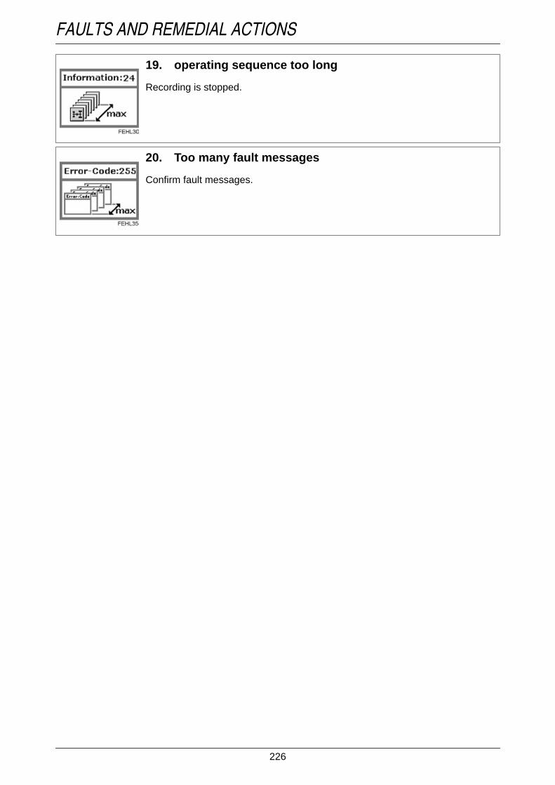
226
FAULTS AND REMEDIAL ACTIONSFault-module
Fault-module
19. operating sequence too long
Recording is stopped.
20. Too many fault messages
Confirm fault messages.

227
FAULTS AND REMEDIAL ACTIONS
3. Warning and information messages for imple-ment settings
Operation_Pic_number:1
Warning and information messages (A) are shown on the Vario terminal.Fault-module
Fault-module
Fault-module
Fault-module
Fault-module
Fault-module
1. Engine speed is less than 400 rpm
Process is not started.Increase engine speed.
2. Transmission not in neutral
Process is not started.Put transmission into neutral.
3. FRONT power lift/PTO automatic mode active on theoperating console
Process is not started.End FRONT power lift/PTO automatic function on the control console.
4. REAR power lift/PTO automatic mode active on theoperating console
Process is not started.Switch off REAR power lift/PTO automatic mode on the operating console.
5. FRONT and REAR power lift/PTO automatic mode activeon the operating console
Process is not started.Switch off FRONT and REAR power lift/PTO automatic mode on the operatingconsole.
6. Variotronic Ti information message active
Fig.4

228
FAULTS AND REMEDIAL ACTIONS
4. Flame starting system faultsThe flame starting system control unit detects faults in the flame starting system, and indicates thesewith flash codes on the preheating indicator lamp.The flashing duration is about 60 secs.
Operation_Pic_number:1
Text-module
The following faults are detected:
Fault code A:● Break in the flame glow plug element loop or its supply line.
Fault code B:● Faulty fuse for the flame start control unit or no supply voltage (B+).
Fault code C:● Break in the solenoid valve line or coil.
In all cases, only the indicator lamp flashes. Solenoid valve and flame heater plug remain switched off.
Fig.5

229
FAULTS AND REMEDIAL ACTIONS
5. Fault code tablesText-module
General
Text-module
Electronic engine control
Fault code Cause Effect and remedy0.0.11 Data transfer from No forward/reverse indicator,0.0.12 Tractor electronic system for 4-WD, diff. lock and0.0.13 instrument cluster inoperative. Front/rear PTO speed.0.0.140.0.150.0.160.0.170.0.180.0.1A0.0.200.0.1B Variotronic Ti data transfer
faulty.Auxiliary operation.
0.0.1F Joystick data transfer faulty. Valves, electronic accelerator, transmis-sion functions not functioning.
0.1.50 Combination instrument notprogrammed.
Programme combination instrument.
0.1.51 Engine oil pressure sensorfaulty.
No more monitoring of engine oil pres-sure.
0.1.54 Sensor for compressed air sup-ply is faulty.
Display no longer valid.
0.1.55 Hydraulic oil supply sensorfaulty.
No monitoring of hydraulic oil level.
0.1.56 Engine temperature sensorfaulty.
Engine temperature is not monitored.
0.1.57 Charge air temperature sensor. No monitoring of intercooler temperature.0.1.59 Sensor for fuel supply faulty. No monitoring of fuel supply indicator.
Fault code Cause Effect and remedy1.1.01 EDC control unit line disconti-
nuity.Normal operation - fault indication.
1.1.03 Foot throttle potentiometerplausibility error.
Accelerator pedal mode not functioning.
1.1.04 Tractor Management System(TMS) checksum error.
Tractor Management System (TMS) notfunctioning, EOL programming.
1.1.05 Engine configuration could notbe read by the electrical enginecontrol module.
Tractor Management System (TMS) notoperational.
1.1.7 E FENDT control unit, line dis-continuity.
Loss of enhanced features, only footthrottle available.
1.1.7F Hand throttle memory buttonsfaulty.
Loss of enhanced features, only footthrottle available.
1.1.9 E Operating console, line discon-tinuity.
Loss of enhanced features, only footthrottle available.
1.1.9F Operating console, line discon-tinuity.
Loss of enhanced features, only footthrottle available.
1.1.A0 Connection to EDC control unit,EDC control unit faulty.
Normal operation - fault indication.
1.1.A1 FENDT control module to EDCcontrol module connectionfaulty.
Reduced engine power.

230
FAULTS AND REMEDIAL ACTIONS
Text-module
Electronic engine control
1.1.BO Communication driver initialisa-tion error; limited CAN buscommunication.
EOL programming.
1.1.EO Calibrated values from manualthrottle rotary control incorrect.
Manual throttle rotary control calibration.
Fault code Cause Effect and remedy1.2.13 Battery voltage too low. Reduced engine operation.1.2.17 Engine overspeed. After the overspeed is left, normal opera-
tion.1.2.18 Start of injection incorrectly set. Reduced end speed, reduced engine
power. Check fuel system.1.2.1A Needle movement sensor in-
correct values.Engine control changed.
1.2.9B Solenoid valve has incorrectvalues.
Reduced end speed, reduced enginepower.
1.2.1E Injection pump. Reduced speed, reduced engine power.1.2.1F Engine control unit or connec-
tion interrupted.Auxiliary operation.
1.2.21 FENDT control module totransmission bus connection in-terrupted.
Optimum engine control not possible.
1.2.23 FENDT control module to EDCcontrol module connection in-terrupted.
Loss of enhanced features, only footthrottle available.
1.2.25 Main relay does not open. Battery is discharged.1.2.2A FENDT control module to EDC
control module connection in-terrupted.
Normal operation - fault indication.
1.2.2B FENDT control module to EDCcontrol module connection in-terrupted.
No control of engine brake.
1.2.2C FENDT control unit connectionto engine brake interrupted.
No control of engine brake.
1.2.2D FENDT control module to EDCcontrol module connection in-terrupted.
Loss of enhanced features, only footthrottle available.
1.2.2 E FENDT control module to EDCcontrol module connection in-terrupted.
Optimum engine control not possible.
1.2.38 Control unit. Reduced speed, reduced engine power.1.2.42 Injection pump. Reduction in power.1.2.46 Control unit. Loss of enhanced features, only foot
throttle available.1.2.81 Pedal position sensor signal
wrong.Normal operation - fault indication.
1.2.82 Injection pump, supply of flow. Engine cuts out, engine does not start.1.2.84 Engine speed sensor, control
module.Reduced speed, reduced engine power.
1.2.85 Boost pressure sensing device. Reduced engine power.1.2.87 Temperature sensor (coolant),
control module.Reduced engine power.
1.2.89 Injection pump. Engine does not start.1.2.91 rpm sensor. Reduced speed, reduced engine power.1.2.92 Injection pump, engine control
module.Reduced end speed, reduced enginepower.
Fault code Cause Effect and remedy

231
FAULTS AND REMEDIAL ACTIONS
Text-module
Implement control
Text-module
1.2.96 Control unit. Engine cuts out.1.2.99 Control unit to injection pump
connection is interrupted.Reduced speed, reduced engine power.
1.2.A2 Engine control unit or injectionpump.
Reduced speed, reduced engine power.
1.2A6 Engine control unit or injectionpump.
Reduced speed, reduced engine power.
1.2.A8 Engine control unit has wrongvalue.
Normal operation - fault indication.
1.2.A9 Injection pump. Reduced end speed, reduced enginepower.
1.2.B1 Control unit to injection pumpconnection is interrupted.
Reduced speed, reduced engine power.
1.2.B2 Control unit, injection pump. Reduced speed, reduced engine power.1.2.B3 Interrupted power supply. Engine stops, engine does not start.1.2.B4 Control unit to injection pump
connection is interrupted.Loss of enhanced features, only footthrottle available.
1.2.B5 Control unit, injection pump. Reduced speed, reduced engine power.1.2.B6 Control unit, injection pump. Reduced speed, reduced engine power.1.2.B7 Engine speed sensor. Reduced speed, reduced engine power.1.2.B9 Control unit, injection pump. Engine stops.1.2.C1 Pump control unit faulty. Engine goes into idle.1.2.C3 EDC control module - pump
controller connection interrup-ted.
Engine goes into idle.
1.2.C4 Injection pump. Engine goes into idle.1.2.C5 Stop solenoid valve. Reduced speed, reduced engine power.1.2.C7 Injection pump, fuel lines faulty. Engine stops. Check fuel system.1.2.C8 Control unit, needle movement
sensor, boost pressure sensor.Engine stops.
1.2.C9 Injection pump. Normal operation - fault indication.1.2.CA Injection timing mechanism va-
lues not within tolerance.Reduced rpm, reduced engine power.Check fuel system.
1.2CB Control unit to injection pumpconnection is interrupted.
Loss of enhanced features, only footthrottle available.
1.2.CD Injection pump. Reduced speed, reduced engine power.1.2.DE Control unit. Loss of enhanced features, only foot
throttle available.1.2.EO EDC control unit not connec-
ted.Normal operation - fault indication.
1.2.E1 PTO rpm or speed signal incor-rect.
Normal operation - fault indication.
Fault code Cause Effect and remedy2.1.EO CAN communication E-Box -
CAN joystick defective.Implements can no longer be controlledusing the joystick.
2.1.EE LBS job computer inoperative. Check CAN bus system for implementcontrol.
2.1.EF Error message from mountedimplement.
Refer to implement manufacturer's ma-nual.
Fault code Cause Effect and remedy

232
FAULTS AND REMEDIAL ACTIONSOperating console
Text-module
Transmission
Fault code Cause Effect and remedy3.1.013.1.023.1.033.1.04 Programming error. Call workshop.3.1.053.1.06
Fault code Cause Effect and remedy4.1.01 Joystick acceleration switch
I-IV faulty.Auxiliary operation.
4.1.04 Clutch pedal potentiometerfaulty.
No monitoring of transmission ratios.
4.1.05 Pressure sensor II defective. Reduced comfort.4.1.06 Accelerator rotary control faulty. Load limit control not functioning.4.1.07 High-pressure sensor faulty. Peak loads in the transmission are no
longer monitored.4.1.08 Operating range I/II analogue
device (function angle device)faulty.
Operating range switching I/II not opera-tional.
4.1.20 Accelerator cancellation rotarycontrol incorrectly calibrated ornot calibrated.
Accelerator mode not working.
4.1.21 Reverse mode switch is defec-tive.
Reverse mode operation and acceleratormode no longer possible.
4.1.22 Accelerator cancellation rotarycontrol faulty.
Restriction in operation of acceleratormode.
4.1.23 Joystick signal Tempomat onfaulty.
Auxiliary operation.
4.1.24 Hand brake switch faulty. Hand brake automatic mode not working.4.1.25 Joystick F-R quick reverse si-
gnal faulty.Auxiliary operation.
4.1.26 Joystick signal acceleratormode faulty.
Accelerator mode not working.
4.1.27 Armrest signal rapid reversal(F/R rocker) faulty.
Rapid reverse not working.
4.1.28 Track width adjustment faulty. Auxiliary operation.4.1.29 Joystick park position signal
faulty.Auxiliary operation.
4.1.2A Bevel pinion rpm sensor direc-tion signal faulty.
Auxiliary operation.
4.1.2B Driving mode I/II selection but-ton faulty.
Tractor remains in current dricing mode.No further selection until ignition ON/OFF.
4.1.2C 'Neutral selection' button faulty. Auxiliary operation.4.1.2D Quick Reverse button (steering
column) faulty.Quick Reverse only available with thejoystick.
4.1.2E Joystick key 'v+' faulty. Auxiliary operation.4.1.2F Joystick v- faulty. Auxiliary operation.4.1.31 Direction signal speed sensor
for hydrostatic unit faulty.Auxiliary operation.
4.1.32 Joystick activating button faulty. Auxiliary operation.4.1.42 Speed sensor hydrostatic unit
faulty.Auxiliary operation.

233
FAULTS AND REMEDIAL ACTIONS
4.1.44 Speed sensor engine 1 faulty. Auxiliary operation.4.1.45 Bevel pinion speed sensor
faulty.Auxiliary operation.
4.1.50 Transmission oil filter dirty. Auxiliary operation.4.1.53 Transmission oil temperature
over 110°.Damage to traction drive.
4.1.58 Slip values of transmission ra-tios beyond acceptable limits.
Occasional occurrences in extreme con-ditions have no effect. If the problem per-sists in normal conditions, contact theworkshop immediately.
4.1.59 Emergency operation manuallyinduced or by electrical activa-tion; emergency operation de-fective when operated non-ma-nually.
Fault code not in the memory.
4.1.61 Faulty activation of operatingrange I valve.
Auxiliary operation.
4.1.62 Faulty activation of operatingrange II valve.
Auxiliary operation.
4.1.63 Faulty activation of valve formechanical speed limitation.
Max. speed 30 km/h only.
4.1.64 Faulty actuation of turboclutchvalve.
Auxiliary operation.
4.1.65 Faulty activation of cardanbrake.
Call workshop.
4.1.66 Faulty activation of cardanbrake.
Call workshop.
4.1.67 Faulty activation of cardanbrake.
Call workshop.
4.1.70 Tempomat cruise control 1 keyfaulty.
No Tempomat cruise control.
4.1.71 Tempomat cruise control 2 keyfaulty.
No Tempomat cruise control.
4.1.72 Filter contamination switch de-fective.
No monitoring of filter contamination.
4.1.73 Temperature output sensorfaulty.
No temperature output monitoring.
4.1.74 Parking brake position recogni-tion switch faulty.
Hand brake position not detected, nohand brake automatic mode.
4.1.76 Engine brake switch faulty. No engine brake function.4.1.77 Joystick acceleration rate I-IV
faulty.Operation only possible in accelerationrate III.
4.1.78 Starting cut-out seat switch foraccelerator mode faulty.
Selection of direction of travel is alwaysdeactivated in accelerator mode whenvehicle stationary for 3 seconds.
4.1.82 Plausibility error (enginespeed) between hydrostaticunit speed sensor and bevel pi-nion speed sensor.
Auxiliary operation.
4.1.83 Plausibility error (direction) bet-ween hydrostatic unit speedsensor and bevel pinion speedsensor.
Auxiliary operation.
4.1.84 Plausibility error between thejoystick controls (F/R, Tempo-mat cruise control).
Auxiliary operation.
4.1.85 Engine speed sensor I plausibi-lity error.
Auxiliary operation.
Fault code Cause Effect and remedy

234
FAULTS AND REMEDIAL ACTIONS
Text-module
Transmission
4.1.86 Plausibility error between pres-sure sensor I and pressure sen-sor II.
Reduced comfort.
4.1.87 Plausibility error on F/R buttonon steering column.
No F/R function on steering column.
4.1.88 Plausibility error on ON/OFFbutton for accelerator pedaldrive.
No function.
4.1.94 CAN communication E-Boxand joystick faulty.
Joystick functions restricted. Call work-shop.
Fault code Cause Effect and remedy4.1.A0 Adjuster actuation faulty. Auxiliary operation.4.1.A1 Control unit mechanical stop
defective.Auxiliary operation.
4.1.A2 Faulty CAN bus connection tocontrol unit.
Auxiliary operation.
4.1.A3 Control unit incremental sensorfaulty / not plausible.
Auxiliary operation.
4.1.A4 Adjuster EST track signal faul-ty/missing.
Auxiliary operation.
4.1.A5 Adjuster reference not found. Auxiliary operation.4.1.A6 Incorrect control unit reference
point during operation.Auxiliary operation.
4.1.B0 Initialisation error on communi-cation driver. CAN bus commu-nication restricted.
Restricted operation.
4.1.B1 Fatal error range control withsubsequent emergency opera-tion (e.g. valve fault).
Auxiliary operation.
4.1.B2 Transmission ratio limitingfaulty.
EOL programming.
4.1.B3 Quick Reverse accelerationrate parameters out of tole-rance.
EOL programming.
4.1.B4 Engine speed sensor I plausibi-lity error.
EOL programming.
4.1.B5 Rapid reversing ramp parame-ter for Tractor Management Sy-stem (TMS) checksum error.
Rapid reversing not operational in theTractor Management System (TMS).
4.1.EO Turboclutch characteristic faul-ty/incorrectly memorised.
EOL programming.
4.1.E1 Traction control pressure regu-lator parameter fault/read error.
EOL programming.
4.1.E2 Pressure regulator parametersin traction control are not plau-sible or read in incorrectly.
No traction control function.
4.1.E3 Accelerator checksum error. EOL programming.4.1.E4 Brake control checksum error. EOL programming.4.1.E9 Values of operating range shift
II-I not within tolerance.Only shift while at a standstill.
4.1.EA Incorrect EOL programming. Auxiliary operation.4.1.EB Range-change values out of to-
lerance or range-change notcalibrated.
Auxiliary operation.
Fault code Cause Effect and remedy

235
FAULTS AND REMEDIAL ACTIONS
Text-module
Four-wheel drive and differential lock
Text-module
Suspension
Text-module
4.1.EC Accelerator rotary control va-lues not within tolerances or nocalibration of accelerator rotarycontrol.
Auxiliary operation.
4.1.ED Clutch pedal potentiometer va-lues out of tolerance or clutchnot calibrated.
Auxiliary operation.
4.1.EE Transmission characteristic va-lues out of tolerance or no cali-bration of transmission.
Auxiliary operation.
4.1.EF Turboclutch values out of tole-rance or no calibration.
Auxiliary operation.
4.1.FF Error in transmission EST con-trol unit.
Auxiliary operation.
Fault code Cause Effect and remedy5.1.31 100% 4-WD button faulty. '4-WD automatic mode' available only.5.1.32 Key for automatic 4WD faulty. '100% 4-WD' available only.5.1.33 Faulty 4-WD clutch solenoid
valve.Function terminated, 4-WD engages.
5.1.34 Steering angle sensor 1 faulty. 4-WD / differential lock automatic modeStop not functioning.
5.1.35 Steering angle sensor 2 faulty. 4-WD / differential lock automatic modeStop not functioning.
5.1.51 100% differential lock buttonfaulty.
Only 'Differential lock automatic mode'function available.
5.1.52 Key for automatic differentiallock faulty.
'100% differential lock' is only functionstill available.
5.1.53 Differential lock solenoid actua-tion faulty.
End of function, differential lock not dis-engaging.
5.1.54 Left brake pedal switch faulty. '100% differential lock' is only functionstill available.
5.1.55 Right brake pedal switch faulty. '100% differential lock' is only functionstill available.
Fault code Cause Effect and remedy5.1.61 Front axle suspension position
sensor faulty.Front axle suspension does not function.Possible to continue without suspension.
5.1.62 Front axle suspension "Raise"solenoid actuation faulty.
Front axle suspension does not function.Possible to continue without suspension.
5.1.63 Incorrect activation of solenoidvalve 'lower'for front axle sus-pension.
Front axle suspension does not function.Possible to continue without suspension.
5.1.64 Front axle suspension on/offkey defective.
Front axle suspension does not function.Possible to continue without suspension.
5.1.65 Lock front axle suspension keyfaulty.
Locking of front axle suspension no lon-ger possible.
5.1.6 E No calibration of position sen-sor.
Front axle suspension does not function.Readjust position sensor.
Fault code Cause Effect and remedy

236
FAULTS AND REMEDIAL ACTIONSPower lift and PTO automatic mode
Text-module
Hydraulic system (push button / flow controller)
Text-module
Other fault codes
Text-module
Rear PTO
Fault code Cause Effect and remedy5.1.91 Joystick rear automatic mode
on/off button faulty.Rear automatic mode not working.
5.1.93 Joystick front automatic modeon/off button faulty.
Front automatic mode not functioning.
5.1.95 Joystick automatic mode stopbutton faulty.
Automatic mode cannot be switched onand off.
Fault code Cause Effect and remedy5.1.98 Control pump oil pressure mo-
nitoring faulty.Possible failure of work hydraulics.
5.1.99 Signal of flow control sensordisturbed or no oil pressure onthe auxiliary pump.
Possible failure of auxiliary pump (con-stant displacement pump).
Fault code Cause Effect and remedy5.1.00 Control unit fault. E-Box faulty.5.1.8D Checksum error. Old automatic
mode configuration data.Reduced comfort.
5.1.8F Checksum error. Old automaticfunction sequential data.
Reduced comfort.
5.1.9A Plausibility check error on flowcontroller with ignition ON andengine OFF.
No pressure monitoring.
5.1.9B 8 bar pressure switch faulty. No pressure monitoring.5.1.B0 Initialisation error on communi-
cation driver. CAN bus commu-nication restricted.
EOL programming.
5.1.9E Engine coolant level too low orempty.
Risk of engine damage. Once the war-ning has been confirmed, the error mes-sage is output every 120 sec. if the coo-lant has not be topped up.
5.1.9F Engine coolant level sensor de-fective.
No coolant level monitoring.
5.1.FF Comfort E-box no longer recei-ving CAN data for enginespeed and PTO speed.
Various indicators no longer available orcomfort E-box fails completely.
Fault code Cause Effect and remedy6.1.01 Button in cab faulty. Does not function, PTO disengages.6.1.02 Key on right mudguard faulty. PTO can only be switched on/off with the
cab button. Button must be pressed for atleast 5 secs.
6.1.03 Button on left mudguard faulty. PTO can only be switched on/off with thecab button. Button must be pressed for atleast 5 secs.
6.1.04 PTO shaft clutch solenoid valvefaulty.
Does not function, PTO disengages.

237
FAULTS AND REMEDIAL ACTIONS
Text-module
6.1.05 PTO shaft rpm sensor faulty. PTO can only be switched on/off with thecab button. Button must be pressed for atleast 5 secs.
6.1.10 Speed sensor shaft faulty.6.1.11 Automatic mode on operating
console faulty.Automatic mode is ended and PTO dis-engages.
6.1.15 Neutral speed selection keyfaulty.
Does not function, PTO disengages.
6.1.16 Selection range key 540 faulty. No function of range selection key 540.6.1.17 Setting 540E selection button
faulty.Setting 540E selection button does notfunction.
6.1.18 Speed selection key 1000faulty.
No function of speed selection key 1000.
6.1.1A Setting 540 valve faulty. Does not function, PTO disengages.6.1.1B Control valve 540E faulty. Does not function, PTO disengages.6.1.1C Control valve 1000 faulty. Does not function, PTO disengages.6.1.41 Cab button plausibility error. Does not function, PTO disengages.6.1.42 Right mudguard button plausi-
bility error.Does not function, PTO disengages.
6.1.43 Left mudguard button plausibi-lity error.
Does not function, PTO disengages.
6.1.45 PTO clutch rpm sensor plausi-bility error.
PTO can only be operated via keys insidethe cab, key must be kept pressed for atleast 5 secs.
6.1.50 Speed sensor PTO shaft plau-sibility error.
When engaging, the button must be pres-sed for at least 5 secs.
6.1.55 Plausibility error in speed se-lection key neutral.
Does not function, PTO disengages.
6.1.56 Plausibility error in speed se-lector key 540.
No function of 540 selection.
6.1.57 540E setting pre-selection but-ton plausibility error.
No function of 540E selection.
6.1.58 Plausibility error in speed se-lection key 1000.
No function of 1000 selection.
6.1.60 Plausibility error between PTOclutch rpm and PTO stub shaftspeed.
Does not function, PTO disengages.
6.1.BO Initialisation error on communi-cation driver. CAN bus commu-nication restricted.
EOL programming.
6.1.C1 Switch-on speed not reachedfor PTO/power lift automaticmode.
Increase ground speed to more than1 km/h.
6.1.EO Checksum parameter currentcontrol for range shifting faulty.
EOL programming.
6.1.E1 Checksum PTO parameterfaulty.
EOL programming.
Fault code Cause Effect and remedy

238
FAULTS AND REMEDIAL ACTIONSFront PTO
Text-module
EPC-C rear power lift
Text-module
Front power lift
Fault code Cause Effect and remedy7.1.01 PTO key inside the cab faulty. Does not function, PTO disengages.7.1.04 Clutch operation solenoid
faulty.7.1.05 PTO shaft rpm sensor faulty. To engage, the button must be pressed
for at least 5 sec.7.1.09 Automatic front PTO key on
operating console defective.Automatic mode is ended and PTO dis-engages.
7.1.41 Cab button plausibility error. Does not function, PTO disengages.7.1.C1 Switch-on speed not reached
for PTO/power lift automaticmode.
Increase ground speed to more than1 km/h.
Fault code Cause Effect and remedy8.3.11 Lift final stage defective. Control is terminated and locked.8.3.12 Lower final stage defective. Control is terminated and locked.8.3.14 Rear left 'Lift'key is defective. Control is terminated and locked.8.3.15 Left rear "Lower" button faulty. Control is terminated and locked.8.3.16 V regulator less than 1 Volt. Control is terminated and locked.8.3.17 Battery voltage over 18 V. Control is terminated and locked.8.3.18 Rear right 'Lift' key is defective. Control is terminated and locked.8.3.19 Rear right 'Lower' key is defec-
tive.Control is terminated and locked.
8.3.22 Position sensor defective. Control is terminated and locked.8.3.23 Setpoint rotary control defec-
tive.Control is terminated and locked.
8.3.26 Faulty external sensor. Control is terminated and locked.8.3.31 Right draught sensing pin de-
fective.Control is continued
8.3.32 Left load sensor pin faulty. Control is continued8.3.33 Battery voltage less than
10.5 V.Control is continued
8.3.40 Quick Lift switch faulty. Raise and Lower only possible with therear controls.
8.3.41 Fast feed-in button faulty. Fast feed-in does not function.8.3.42 Hitch button faulty. Hitch key not functioning.8.3.43 Automatic rear lifting gear key
(control console) defective.Automatic rear lifting gear key not opera-tional.
8.3.50 Warning, right load sensor pinoverloaded.
Warning is not stored. Relieve draftingsensing pin of load.
8.3.51 Warning, left load sensor pinoverloaded.
Warning is not stored. Relieve draftingsensing pin of load.
Fault code Cause Effect and remedy9.1.50 Valve not registered on CAN-
bus.Valve actuation not possible.
9.1.5F Incorrect messages sent onCAN bus. Electronics in valvefaulty.
Valve goes into neutral position.
9.1.51 Electronics in valve faulty. Valve goes into neutral position. Replacevalve.

239
FAULTS AND REMEDIAL ACTIONS
Text-module
9.1.52 Voltage in the valve less than8 V.
Valve goes into neutral position.
9.1.53 Voltage in excess of 18 V. Valve goes into neutral position.9.1.54 Valve actuator falls short. Drops
in control pressure or oil too vis-cous at low temperatures.
Valve goes into neutral position.
9.1.5A Valve actuator goes too far. Valve goes into neutral position.9.1.5B Floating position not reached. Valve goes into neutral position.9.1.5C Manual actuation. None.9.1.55 High overvoltage over 45 V. Valve goes into neutral position.9.1.56 Final stage error (pilot control
solenoid valve).Valve goes into neutral position.
9.1.57 Position pickup sensor error. Valve goes into neutral position.9.1.58 Valve actuator does not return. Valve slide jams.9.1.59 Slide valve jams because of
dirt.Valve slide jams.
9.1.A0 No memorised values after en-gine re-start.
Reduced driving comfort.
9.1.A19.1.B0 Position sensor is not cali-
brated.No position control possible.
9.1.B1 Position sensor transmits novalues or wrong values.
No position control possible.
9.1.B2 Set point rotary control not cali-brated.
Setpoint values cannot be set.
9.1.B3 Setpoint potentiometer sendsno values or incorrect values.
Setpoint values cannot be set.
9.1.C0 Operating console not availa-ble.
No automatic mode, no general locking.
9.1.C1 Automatic mode button faulty. No automatic mode.9.1.C2 Overall locking key faulty. No overall locking of valves.9.1.C3 Floating position button faulty. No floating position.9.1.C4 Front power lift Raise button
faulty.Front power lift cannot be raised properly.
9.1.C5 Front power lift 'Lower' faulty. Front power lift cannot be lowered pro-perly.
9.1.C6 Possible fault on CAN bus tooperating console.
Status changes cannot be detected. En-gagement/disengagement possibly beingoverridden.
9.1.C79.1.C89.1.C99.1.CA9.1.D0 External Lift key faulty. Front power lift cannot be lowered pro-
perly.9.1.D1 External Lower key faulty. Front power lift cannot be lowered pro-
perly.9.1.D2 External key actuates twice or
key sticks.Front power lift cannot be lowered pro-perly.
Fault code Cause Effect and remedy

240
FAULTS AND REMEDIAL ACTIONSElectric valves (oeprating console)
Text-module
Electric valves (crossgate lever)
Text-module
Electric valves (buttons / switches)
Fault code Cause Effect and remedyA.1.C0 Control console not available,
e.g. CAN-bus not connected.No automatic mode. No general lockingof valves.
A.1.C1 Automatic mode button faulty. No automatic mode.A.1.C2 Overall locking key faulty. No overall locking of valves.A.1.C3 Floating position button faulty. No floating position.A.1.C4 Timer function button faulty. No timer function.A.1.C5 Crossgate lever/joystick swit-
chover button faulty.Not possible to switch between crossgatelever operation and joystick operation.
A.1.C6 Operating console CAN busfaulty.
Change of status not detected. Switchingon/off is ignored. Valve locked.
A 1.C7A.1.C8A.1.C9A.1.CAA.1.CB CAN joystick not available. Not possible to operate valves.A.1.CC E-Box and CAN joystick CAN
connection faulty.Limited operation of valves.
Fault code Cause Effect and remedyA.1.B0 Crossgate lever not adjusted. Valves cannot be actuated. Carry out ad-
justment.A.1.B1 Signal fault. Valve position cannot be controlled pro-
perly.A.1.B2A.1.B3A.1.B4A.1.B5 Crossgate lever recognition of
centre position faulty.Valve position cannot be operated accu-rately. Calibrate.
Fault code Cause Effect and remedyA.1.FA External valve actuation. Spool
valve external pushbutton forrear LIFT faulty.
Rear external controls not working.
A.1.FB External valve actuation. Spoolvalve external pushbutton forrear LOWER faulty.
Rear external controls not working.
A.1.FC External valve actuation. Spoolvalve external pushbutton rearactuates twice or pushbutton isfaulty.
Change controls or exchange keys.
A.1.D1 Valve 3, signal disturbed orfaulty valve.
'Lift' and/or 'Lower' valve 3 faulty.
A.1.D3 Valve 4, signal disturbed orfaulty valve.
'Lift' and/or 'Lower' valve 4 faulty.
A.1.D4 Faulty solenoid switch for re-lease of external controls ofstandard front power lift.
Position of shutoff cock for front power liftcannot be detected.
A.1.D5 External front power lift 'Lower'button faulty.
Front power lift cannot be lowered pro-perly.

241
FAULTS AND REMEDIAL ACTIONS
Text-module
Electrical valves (valve 1)
Text-module
A.1.D6 External front power lift 'Raise'button faulty.
Front power lift cannot be raised properly.
A.1.D7 Hydraulic oil level sensor faulty. Hydraulic oil level no longer monitored.A.1.D9 Hydraulic tank is empty. Possible damage to pump or undesired
valve responses.A.1.DA Kickout push button faulty. No Kickout function.A.1.DB Hydraulic oil characteristic not
plausible.Incorrect display of hydraulic oil supply.Reprogramme EOL.
A.1.DC Priority volume of hydraulic oilgreater than pump volume.
Reduce priority hydraulic oil quantity.
A.1.DD Front external key actuatestwice or key sticks.
Front power lift cannot be lowered pro-perly.
Fault code Cause Effect and remedyA.1.10 Valve not registered on CAN
bus.Valve actuation not possible.
A.1.1F CAN-BUS error, valves. Valves locked.A.1.11 Electronics in valve faulty. Valve goes into neutral position.A.1.12 Voltage in the valve less than
8 Volt.Valve goes into neutral position.
A.1.13 Voltage in excess of 18 V. Valve goes into neutral position.A.1.14 Valve actuator falls short. Valve goes into neutral position.A.1.1A Valve actuator goes too far. Valve goes into neutral position.A.1.1B Floating position not reached. Valve goes into neutral position.A.1.1C Manual actuation.A.1.15 High overvoltage over 45 V. Valve goes into neutral position.A.1.16 End stage error (end stage for
pilot control solenoid).Valve goes into neutral position.
A.1.17 Position pickup sensor error. Valve goes into neutral position.A.1.18 Valve actuator does not return
to neutral position.Valve remains set.
A.1.19 Valve actuator not in neutral po-sition when switched on.
Valve remains set.
Fault code Cause Effect and remedy
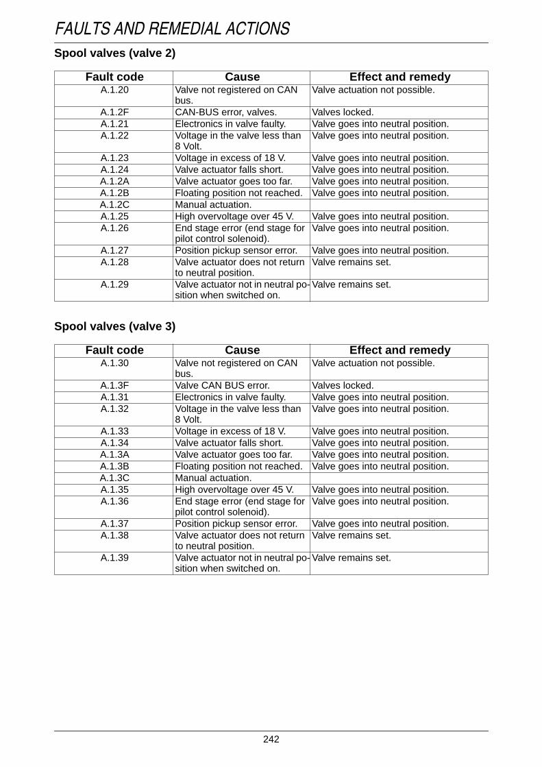
242
FAULTS AND REMEDIAL ACTIONSSpool valves (valve 2)
Text-module
Spool valves (valve 3)
Text-module
Fault code Cause Effect and remedyA.1.20 Valve not registered on CAN
bus.Valve actuation not possible.
A.1.2F CAN-BUS error, valves. Valves locked.A.1.21 Electronics in valve faulty. Valve goes into neutral position.A.1.22 Voltage in the valve less than
8 Volt.Valve goes into neutral position.
A.1.23 Voltage in excess of 18 V. Valve goes into neutral position.A.1.24 Valve actuator falls short. Valve goes into neutral position.A.1.2A Valve actuator goes too far. Valve goes into neutral position.A.1.2B Floating position not reached. Valve goes into neutral position.A.1.2C Manual actuation.A.1.25 High overvoltage over 45 V. Valve goes into neutral position.A.1.26 End stage error (end stage for
pilot control solenoid).Valve goes into neutral position.
A.1.27 Position pickup sensor error. Valve goes into neutral position.A.1.28 Valve actuator does not return
to neutral position.Valve remains set.
A.1.29 Valve actuator not in neutral po-sition when switched on.
Valve remains set.
Fault code Cause Effect and remedyA.1.30 Valve not registered on CAN
bus.Valve actuation not possible.
A.1.3F Valve CAN BUS error. Valves locked.A.1.31 Electronics in valve faulty. Valve goes into neutral position.A.1.32 Voltage in the valve less than
8 Volt.Valve goes into neutral position.
A.1.33 Voltage in excess of 18 V. Valve goes into neutral position.A.1.34 Valve actuator falls short. Valve goes into neutral position.A.1.3A Valve actuator goes too far. Valve goes into neutral position.A.1.3B Floating position not reached. Valve goes into neutral position.A.1.3C Manual actuation.A.1.35 High overvoltage over 45 V. Valve goes into neutral position.A.1.36 End stage error (end stage for
pilot control solenoid).Valve goes into neutral position.
A.1.37 Position pickup sensor error. Valve goes into neutral position.A.1.38 Valve actuator does not return
to neutral position.Valve remains set.
A.1.39 Valve actuator not in neutral po-sition when switched on.
Valve remains set.

243
FAULTS AND REMEDIAL ACTIONSSpool valves (valve 4)
Text-module
Electric valves (E-box)
Text-module
Fault code Cause Effect and remedyA.1.40 Valve not registered on the
CAN bus.Valve actuation not possible.
A.1.4F CAN-BUS error, valves. Valves locked.A.1.41 Electronics in valve faulty. Valve goes into neutral position.A.1.42 Voltage in the valve less than
8 Volt.Valve goes into neutral position.
A.1.43 Voltage in excess of 18 V. Valve goes into neutral position.A.1.44 Valve actuator falls short. Valve goes into neutral position.A.1.4A Valve actuator goes too far. Valve goes into neutral position.A.1.4B Floating position not reached. Valve goes into neutral position.A.1.4C Manual actuation.A.1.45 High overvoltage over 45 V. Valve goes into neutral position.A.1.46 End stage error (end stage for
pilot control solenoid).Valve goes into neutral position.
A.1.47 Position pickup sensor error. Valve goes into neutral position.A.1.48 Valve actuator does not return
to neutral position.Valve remains set.
A.1.49 Valve actuator not in neutral po-sition when switched on.
Valve remains set.
Fault code Cause Effect and remedyA.1.A0 EEPROM error. Loss of enhanced features when opera-
ting valves.A.1.A1A.1.A2 More valves connected than
are registered through end-of-line programming. Undertakeprogramming.
Not all valves can be operated.
A.1.FO Valve control for the switchingof the pilot control of all electri-cal valves with front power liftfaulty.
All valves go into neutral position.
A.1.F1 Valve control for the heating ofall electrical valves with frontpower lift faulty.
Reduced operation in cold conditions.
A.1.F2 Valve control for switching thepilot control of all spool valveswith front power lift faulty.
Call workshop.
A.1.F3 Valve control for switching thepilot control of all spool valveswith front power lift has inter-rupted supply line.
Call workshop.

244
FAULTS AND REMEDIAL ACTIONSVariotronic Ti
Fault code Cause Effect and remedyB.1.11 Electrical fault, automatic
mode.Call workshop.
B.1.12 Electrical fault, terminal. Call workshop.B.1.21 Communications error, internal
communication.Call workshop.
B.1.22 Communications error betweenterminal and Variotronic Ti.
Call workshop.
B.1.23 Communications error betweencontrol console and VariotronicTi.
Call workshop.
B.1.24 Communications error betweenjoystick and Variotronic Ti.
Call workshop.
B.1.41 Communications error, internalcommunication.
Call workshop.
B.1.42 Communications error betweenterminal and Variotronic Ti.
Call workshop.
B.1.43 Communications error betweencontrol console and VariotronicTi.
Call workshop.
B.1.44 Error counter between joystickand Variotronic Ti.
Call workshop.
B.1.BO Error reader Variotronic Ti. Call workshop.B.1.B4 Error in the memory function. Restart tractor. If error is still there, con-
sult workshop.

245
FAULTS AND REMEDIAL ACTIONS
6. Emergency operation
If the transmission ratio can no longer be set bythe electronic system due to actual or indicatedfaults, the transmission can be controlled me-chanically with the auxiliary lever.The maximum speed in range 2 is 34 km/h forforward travel and 25 km/h for reverse, in range1 the maximum speed for forward travel is15 km/h and 11 km/h for reverse.
Operation_Pic_number:1
● Open cover from the cab floor and remove.● Connect auxiliary lever (A) to transmission
adjustment.
Auxiliary lever is included as standard equip-ment.
DANGER:Turn off the engine, put the drivingmode selector in neutral position(centre position) and apply the handbrake.
CAUTION:After starting the engine, thetransmission is fully engaged if adriving mode (I or II) has beenselected.Since either a transmission ratio or adirection of travel is selected, theclutch pedal must be operatedcarefully.
Fig.6
Activating the emergency operationOperation_Pic_number:1
● Press clutch pedal.● Press button (A/red).
Operation_Pic_number:1
Symbol (B) is now shown on the multiple display.
Symbol (B) is also displayed in the event of afault leading to emergency operation.
When using emergency operation, traveldirection indicators are no longer active.
If activated unintentionally:● Stop the tractor.● Terminate emergency operation by switching
ignition OFF and ON.Text-module
Mechanical selection of transmissionratio
IMPORTANT:When setting the transmission ratio, only thesupplied auxiliary lever should be used, ot-herwise the coupling in the adjuster may beturned too far (max. perm. torque 10 Nm).
● Carefully engage clutch pedal.
The tractor starts moving into the last selectedtravel direction and accelerates up to the selec-ted transmission ratio.
Fig.7
Fig.8

246
FAULTS AND REMEDIAL ACTIONSAuxiliary lever
Operation_Pic_number:1
Operation_Pic_number:1
● If the auxiliary lever (A) is moved to the leftduring forwards travel, the tractor accelera-tes. If the auxiliary lever is moved to the right,the tractor slows down because it is braked.
● If the auxiliary lever is moved to the right whilereversing, the tractor accelerates. If the auxi-liary lever is moved to the left, the tractor isbraked and slows down.
Fig.9
Fig.10
Driving mode selectorOperation_Pic_number:1
● Attach auxiliary device to range control switch(B).
● Operate the clutch pedal.
NOTE:An extension can be used as an aid for selec-ting the driving mode.The max. travel speed for any range selectionis 2 km/h.
Selector directions:
Right = Range I (field).Centre = Neutral position N (neutral).Left = Driving mode II (road).Text-module
Terminating emergency operation● Stop the tractor.● Terminate emergency operation by switching
ignition OFF and ON.
Fig.11
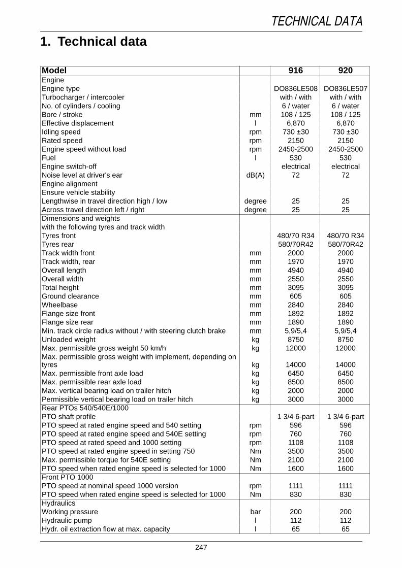
247
TECHNICAL DATA
1. Technical dataText-module
Model 916 920EngineEngine type DO836LE508 DO836LE507Turbocharger / intercooler with / with with / withNo. of cylinders / cooling 6 / water 6 / waterBore / stroke mm 108 / 125 108 / 125Effective displacement l 6,870 6,870Idling speed rpm 730 ±30 730 ±30Rated speed rpm 2150 2150Engine speed without load rpm 2450-2500 2450-2500Fuel l 530 530Engine switch-off electrical electricalNoise level at driver's ear dB(A) 72 72Engine alignmentEnsure vehicle stabilityLengthwise in travel direction high / low degree 25 25Across travel direction left / right degree 25 25Dimensions and weightswith the following tyres and track widthTyres front 480/70 R34 480/70 R34Tyres rear 580/70R42 580/70R42Track width front mm 2000 2000Track width, rear mm 1970 1970Overall length mm 4940 4940Overall width mm 2550 2550Total height mm 3095 3095Ground clearance mm 605 605Wheelbase mm 2840 2840Flange size front mm 1892 1892Flange size rear mm 1890 1890Min. track circle radius without / with steering clutch brake mm 5,9/5,4 5,9/5,4Unloaded weight kg 8750 8750Max. permissible gross weight 50 km/h kg 12000 12000Max. permissible gross weight with implement, depending ontyres kg 14000 14000Max. permissible front axle load kg 6450 6450Max. permissible rear axle load kg 8500 8500Max. vertical bearing load on trailer hitch kg 2000 2000Permissible vertical bearing load on trailer hitch kg 3000 3000Rear PTOs 540/540E/1000PTO shaft profile 1 3/4 6-part 1 3/4 6-partPTO speed at rated engine speed and 540 setting rpm 596 596PTO speed at rated engine speed and 540E setting rpm 760 760PTO speed at rated speed and 1000 setting rpm 1108 1108PTO speed at rated engine speed in setting 750 Nm 3500 3500Max. permissible torque for 540E setting Nm 2100 2100PTO speed when rated engine speed is selected for 1000 Nm 1600 1600Front PTO 1000PTO speed at nominal speed 1000 version rpm 1111 1111PTO speed when rated engine speed is selected for 1000 Nm 830 830HydraulicsWorking pressure bar 200 200Hydraulic pump l 112 112Hydr. oil extraction flow at max. capacity l 65 65

248
TECHNICAL DATA
Text-module
Rear power liftThree-point cat. 2/3 cat. 2/3Control EPC EPCMaximum lifting power at drawbar kN 95,5 95,5Front power lift (optional)Three-point Cat. 2 Cat. 2Max. lifting power kN 50,0 50,0Weight of implement at coupling point kg 3600 3600TransmissionContinuously variable Vario transmission km/h 50 50Range I forwards km/h 0,02 - 32 0,02 - 32Driving mode I reverse km/h 0,02 - 20 0,02 - 20Driving mode II forwards km/h 0,02 - 50 0,02 - 50Driving mode II reverse km/h 0,02 - 38 0,02 - 38Electrical systemOperating tension V 12 12Battery V/Ah 2x 12/90 2x 12/90Alternator W/V/A 2520/14/2x90 2520/14/2x90Starter kW 4,0 4,0Tightening torques for wheels (threads and contact surfaceslightly oiled)Front wheels Nm 450 450Rear wheels Nm 620 620
Model 916 920

249
TECHNICAL DATA
Model 924 926 930EngineEngine type DO836LE506 DO836LE505 DO836LE510Turbocharger / intercooler with / with with / with with / withNo. of cylinders / cooling 6 / water 6 / water 6 / waterBore / stroke mm 108 / 125 108 / 125 108 / 125Effective displacement l 6,870 6,870 6,870Idling speed rpm 810 ±30 810 ±30 810 ±30Rated speed rpm 2250 2250 2250Engine speed without load rpm 2510-2550 2510-2550 2510-2550Fuel l 530 530 530Engine switch-off electrical electrical electricalNoise level at driver's ear dB(A) 72 72 72Engine alignmentEnsure vehicle stabilityLengthwise in travel direction high / low degree 25 25 25Across travel direction left / right degree 25 25 25Dimensions and weightswith the following tyres and track widthTyres front 540/65 R34 600/65 R34 600/65 R34Tyres rear 650/65R42 650/85R38 710/70R42Track width front mm 2000 2000 2000Track width, rear mm 1970 1970 1970Overall length mm 4940 4940 4940Overall width mm 2580 2640 2700Total height mm 3110 3110 3110Ground clearance mm 605 605 605Wheelbase mm 2840 2840 2840Flange size front mm 1892 1892 1892Flange size rear mm 1890 1890 1890Min. track circle radius without / with steeringclutch brake mm 5,9/5,4 5,9/5,4 5,9/5,4Unloaded weight kg 8800 8800 8950Max. permissible gross weight 50 km/h kg 12000 12000 12000Max. permissible gross weight with implement,depending on tyres kg 14000 14000 14000Max. permissible front axle load kg 5450 6000 6000Max. permissible rear axle load kg 8500 8500 9500Max. vertical bearing load on trailer hitch kg 2000 2000 2000Permissible vertical bearing load on trailerhitch
kg 3000 3000 3000
Rear PTOs 540/540E/1000PTO shaft profile 1 3/4 6-part 1 3/4 6-part 1 3/4 6-partPTO speed at rated engine speed and 540 set-ting rpm 596 596 596PTO speed at rated engine speed and 540Esetting rpm 760 760 760PTO speed at rated speed and 1000 setting rpm 1108 1108 1108PTO speed at rated engine speed in setting750 Nm 3500 3500 3500Max. permissible torque for 540E setting Nm 2100 2100 2100PTO speed when rated engine speed is selec-ted for 1000 Nm 1600 1600 1600Front PTO 1000PTO speed at nominal speed 1000 version rpm 1111 1111 1111PTO speed when rated engine speed is selec-ted for 1000 Nm 830 830 830

250
TECHNICAL DATA
Text-module
NOTE:Any modifications to the power output limiter and max. speed setting shall render the Warrantyinvalid. This also applies to any exceeding of the maximum permissible loads and weights.
NOTE:For PTO mode:If the maximum permissible torque can be exceeded (depending on the application), use a driveshaft with safety coupling and overrunning clutch if necessary.Maximum failsafe mechanism to prevent blocking at peaks in torque of 4000 Nm.
HydraulicsWorking pressure bar 200 200 200Hydraulic pump l 117 117 117Hydr. oil extraction flow at max. capacity l 65 65 65Rear power liftThree-point cat. 2/3 cat. 2/3 cat. 2/3Control EPC EPC EPCMaximum lifting power at drawbar kN 108,5 108,5 108,5Front power lift (optional)Three-point Cat. 2 Cat. 2 Cat. 2Max. lifting power kN 50,0 50,0 50,0Weight of implement at coupling point kg 3600 3600 3600TransmissionContinuously variable Vario transmission km/h 50 50 50Range I forwards km/h 0,02 - 32 0,02 - 32 0,02 - 32Driving mode I reverse km/h 0,02 - 20 0,02 - 20 0,02 - 20Driving mode II forwards km/h 0,02 - 50 0,02 - 50 0,02 - 50Driving mode II reverse km/h 0,02 - 38 0,02 - 38 0,02 - 38Electrical systemOperating tension V 12 12 12Battery V/Ah 2x 12/90 2x 12/90 2x 12/90Alternator W/V/A 2520/14/2x90 2520/14/2x90 2520/14/2x90Starter kW 4,0 4,0 4,0Tightening torques for wheels (threads andcontact surfaces lightly oiled)Front wheels Nm 450 450 450Rear wheels Nm 620 620 620
Model 924 926 930

251
TECHNICAL DATA
2. Tyre pressures
Text-module
Tyre pressure front1.6 bar.Text-module
Tyre pressure rear1.6 bar.Text-module
CAUTION:Check tyre pressures regularly!
Comply with tyre manufacturer’s recommen-dations.● Pressures may differ according to tractor mo-
del, make of tyre and type of operation e.g.front loader operation.
● For max. traction and min. ground pressure inthe field, adapt tyre pressures to axle load.
● According to German vehicle licensing regu-lations, if tyres bring the vehicle width to 2.5 m- 3.0 m (wide tyres), the maximum tyre pres-sure is 1.5 bar.
● Tyre load capacity is designated by a 'servicedescription' with a load capacity identifier, e.g.145 = 2,900 kg basic load capacity per tyre,and a speed symbol, e.g. A8 = 40 km/h refe-rence speed.
● If 40 km/h tyre is used at 50 km/h, the basicload capacity is reduced by 9 %.
● Do not operate maintenance wheels above amaximum speed of 40 km/h.
● Increase the tyre pressure when operatingthe front loader.

252
TECHNICAL DATA
3. Tyre combinations
Vario 916 - 920Operation_Pic_number:1
1) Separate TÜV certification
Vario 924 - 930Operation_Pic_number:1
1) Separate TÜV certification
Fig.1
Fig.2

253
TECHNICAL DATA
4. Fuel and lubricants Vario 916 - 930Text-module
Filling points Number Type 4) Frequency of change 2)approx. litres
1)Engine Fendt Extra Grade 15W-40 SHPD, Fendt
Ultra Grade 10W-40 UHPD orafter 50, 500, 1000 operating hours
Maximum fill, with change offilter
24.0 SHPD engine oils 3) in accordance withACEA E3-96.
then every 500 hours of operation ora minimum of once every year, withfuel containing up to 0.5 % sulphur5).
Transmission and differential(topping up)
Fendt Extra Trans 10W-40 or every 2 years or after 2000 operatinghours.
Vario 916-920 65.0 STOU SAE 10 W-40 or 15 W-40Vario 924-930 67.0Lift shaft lubrication 0.2 Lifting shaft lubrication (just top up)
after 50 operating hours or if leaking.Axle drives per side Fendt Super Trans 85W-90, 80W or every 500 operating hoursVario 916-920 13.0 Hypoid transmission oil then every 2 years.Vario 924-930 16.0 SAE 85W-90, SAE 80W-90, SAE 90 acc.
to API GL-5.every 2000 op. hrs.
Front PTO 4.2 Do not use STOU or other universal oils.Front axle Fendt Super Trans LS 85W-90 after 50 and 1000 operating hoursDifferential drives 9.5 or hypoid transmission oil with LS additi-
ves.then every 2 years or every 1,000 op.hours
Axle hub per side 4.0 SAE 85W-90, SAE 80W-90, SAE 90 acc.to API GL-5Do not use STOU or other universal oils.
Rear axle shaft (optional) Hypoid transmission oil 85 W-140 in accor-dance with API GL-5.
after 500 operating hours, then every2 years or 2000 operating hours
Axle drives per side 16.0Hydraulic system Fendt Super Hyd, Fendt Extra Hyd 68 or after 1000 op. hours, then every 2 ye-
arsQuantities 70.0 STOU SAE 5W-30, 5W-40, 10W-30,
10W-40, 15W-30,15W-40every 1000 op. hrs.
Maximum capacity 100.0 or engine oil HD-SAE 5W-30, 5W-40,10W-30, 10W-40, 15W-30,15W-40 in ac-cordance with API-CD.HD-SAE 20W-20 to API-CD also allowedfor temperatures above 10 °C
Fuel tank 530.0 Diesel 5) Fill up after use.Cooling system 26.0 water with 35 - 50 % vol. antifreeze and
anticorrosion agent 6)Change antifreeze every 2 years.
Brake and clutch system 0.8 Pentosin CHF 11S (X 902.011.622) every 2 years.Compressed air system 0.5 Ethyl alcohol antifreeze Fill only at temperatures below
+ 5 °C.(X 902.015.003)
Lubrication points Fendt Ultra lithium grease, Fendt ExtraFett EP or
see Lubrication Chart
lithium-saponified grease, NLGI class 2(worked penetration factor 265-295). regularly oil all other joints and be-
aring surfaces.
1. Filling levels are determined with a dipstick or byoverflow at filling screws etc.2. Whichever comes first.4. For registered tradenames, refer to current list ofFluids and Lubricants which is available from everyFendt-authorised workshop.5. If diesel fuel contains more than 0.5 % sulphur, theoil change frequency must be halved. Below 0.05 %we suggest to check and keep the lubricating proper-ties by adding additives. Only use alternative fuels,e.g. RME, once discussed with the Service Workshop.6. Only use coolant as designated in Customer Ser-vice memo 11/02.
Text-module
3) VISCOSITY OF ENGINE OILS
Monograde oils Multigrade oils

254
TECHNICAL DATA4.1 Bio-dieselText-module
Fuel gradeRME R ape seed- M ethyl- E ster,PME V egetable oil- M ethyl- E ster fuelaccording to DIN 51606 are fuels to be used.Cold-pressed rape seed oil cannot be used.Text-module
Maintenance intervalsOil and oil filter change intervals should be hal-ved.After filling a few times with biodiesel, after ha-ving used conventional diesel fuel, the fuel filtermust be replaced. Since biodiesel acts as a sol-vent, diesel residues may block the fuel filter.Text-module
Instructions for useBiodiesel is suitable for winter temperaturesdown to about -10 °C.At temperatures below -10 °C, diesel fuel needsto be added to prevent coagulation of the biodie-sel. 50 % Diesel must be added per tank filling.With temperatures below - 16 °C, use only die-sel.Biodiesel can be mixed in any proportion withdiesel fuel.This may slightly reduce power output.Fuel consumption can be slightly increased.If the tractor is not going to be used for sometime (3 months or more), fill with diesel to pre-vent the fuel injection pump from seizing.Text-module
Special features of biodieselBiodiesel is obtained from plant oil (mainly rapeseed oil) by means of a chemical process, wherethe vegetable oil is mixed with methanol andconverted to biodiesel using a catalyst.Biodiesel is virtually sulphur-free, and the enginetherefore produces almost no SO2 (sulphur di-oxide).The exhaust gases contain- carbon monoxide- hydrocarbons- particulates (e.g soot)than when using conventional diesel.Biodiesel is biodegradable and does not endan-ger ground and water in case of accidents.
4.2 Bio hydraulic oilText-module
Bio hydraulic oil qualitiesUse bio-hydraulic fluid made from vegetable oil,rape seed oil and synthetic oils, according to vis-cosity standard ISO VG 32 - ISO VG 46.
NOTE:Do not use polyglycol-based synthetic oils.Text-module
Maintenance intervalsOil and oil filter need to be changed every 1,000operating hours or every year, whichever comesfirst.After changing over to bio hydraulic oil, changehydraulic oil filter after approx. 10 - 15 operatinghours. BIO hydraulic oil has solvent propertiesand may cause clogging of the filter in reactionwith normal oil.Text-module
Instructions for useBio hydraulic oil is suitable for winter operationsin temperatures down to approx. - 15 °C.Bio hydraulic oil may loose viscosity in outsidetemperatures below -15 °C and prolonged pe-riods of non-operation of the tractor. After a coldstart, allow a short warm-up time at medium en-gine speed to ensure safe operation of the hy-draulic steering and lifting gear. In conditions ofsevere cold, it may be necessary to warm up thewhole tractor.Avoid mixing bio-hydraulic fluid with other oils,e.g with other, normal oil remaining in the sy-stem, or by operating an external implement.This may affect the positive environmental pro-perties of the fluid, and will make it more difficultto dispose of (it will then have to be consideredas special waste).When disposing of oil, current legislation and theinstructions of the oil manufacturer are to be ob-served.A mixing of more than 10% may result in altera-tions in viscosity and may lead to problems withthe valves.Text-module
Special features of bio hydraulic oilIt is biodegradable and ground and ground waterwill not be affected in case of accidental spills.
IMPORTANT:In spite of the high environmental compatibi-lity of bio-hydraulic fluid, accidental spillsmust always be reported.

255
TECHNICAL DATA
5. Lubrication chart
5.1 Filling pointsText-module
Engine:turn dipstick (B) andremove, fill withengine oil (A).
Transmission:Turn dipstick (A) andremove, fill withtransmission oil.
Axle drives, eachside:Pour in oil throughfiller hole (B).
Front axledifferential gear:Fill up to overflow atfiller hole (A).
Front axle hubdrives:fill until the oil spillsover, with hole onthe left and markerin horizontalposition.
Front PTO:Fill up to overflow atfiller hole (A).
Lift shaft:fill until oil is approx.40 mm below fillerhole (A).
Hydraulic system:Unscrew filter cover(A). Fill with oil.
Brake and clutchsystem:Fill container(arrowed) withPentosin CHF 11S.
Cooling system:Pour clean, low-limewater containinganti-freeze into con-tainer (arrowed).
Windshield washersystem:Pour fluid intocontainer (A).
Compressed-airsystem:Fill antifreezecontainer (B) withethyl alcohol.
Fuel tank:fill with fuel throughfiller neck (A).

256
TECHNICAL DATA5.2 Lubrication pointsText-module
Maintenance intervals after:Text-module
125 operating hoursExtendable struts.
Automatic trailerhitch withcylinder-type bolt.
Automatic trailerhitch with ball-typebolt.
Mechanical trailerhitch.
Bottom lift cylinderbearing of front axlesuspension.
Front axle swingarm.
V-belt tensioner.
NOTE:For machines with hydraulic trailer hitch (seeOPERATION Fig. 249).Text-module
250 operating hours
Automaticmudguardadjustment.
Hand brake shaft(A).
Double cardanU-joints onfront-wheel drive.
Front power liftshaft.

257
TECH
NIC
AL DATA
Maintenance ScheduleFENDT 916 Vario, 920 Vario, 924 Vario, 926 Vario, 930 Vario
Vehicle Nos. 916 .. 7001, 920 .. 7001, 924 .. 7001, 926 .. 7001, 930 .. 2001Maintenance jobs during and after the running-in period and for the workshop after the 5th Service
No.
Services regularly 1)
daily
Job Schedule
See also Operating ManualCare and Maintenance
General notes and technical data, types of fluid and oil
Correct levels are determined by dipstick check or from the overflow at theinspection hole.Observe all accident prevention regulations and comply with directives forhandling and disposing of fluid and lubricants.
1.
50
2.
250
3.
500
4.
750
5.
1000
annual orevery500
every 2years
or2000
operating hours
1 EngineX Check oil level. The difference between the MIN and MAX marking on the dipstick is approx.
4.0 litres.
After 100 operating hours add oil to the MAX mark of the dipstick.
Wait until level is just above the MIN marking. Do not fill above MAX marking.
X X X X Replace engine oil and filter cartridge 2). Oil quantity: 24.0 litres
Oil grade: Fendt Extra Grade 15W-40 SHPD, Fendt Ultra Grade10W-40 UHPD or SHPD engine oils acc. to ACEA E3-96.
X 1000 Check valve clearance, adjust if necessary (atworkshop).
Valve clearance: Intake valve 0.5 mm, exhaust valve 0.5 mm, with enginecold (max 50 °C).
X X as re-quired
Clean the filter strainer and filter chamber in thefuel hand pump.
Repeat more often if engine output begins to fall.
X annu-ally
Replace fuel filter unit. Repeat more often if engine output begins to fall.
as re-quired
Replace preliminary fuel filter (optional). Repeat more often if engine output begins to fall.
X X X X Check V-belt, retighten if necessary 1). Air conditionercompressor:
400+50 N (40+5 kp).
Alternator left side. 450+50 N (45+5 kp).
X X V-belt tightener. Adjust to distance of 92 mm between centres.
X X X X X Check coolant level, top up if necessary. Coolant level: With the engine cold, top up if necessary with clean, lime-free water containing antifreeze to between the MIN andMAX mark on the expansion reservoir.
X Replace coolant. Coolant quantity: 26.0 litres
A concentration of 35 - 50% vol. of antifreeze and anticorrosion agent is neces-sary throughout the year, even in frost-free areas.
Add anti-freeze as indicated in Fendt Customer Service memo 11/02.

258
TECH
NIC
AL DATA
X Clean the fan shroud. Clean with high-pressure cleaner - also refer to Fendt Customer Service memo12/02.
as requi-red
Check, and if necessary clean the cooling finson engine, hydraulic system, charge air, trans-mission and air conditioning system.
Blow out with compressed air or with a dust extractor.
X X X X as requi-red
Air filter maintenance. Maintenance required only if a fault (symbol) is indicated on the multiple display.Clean with compressed air at 5 bar max., then check for damage.
X Replace air filter main cartridge.
X X X X Check air filter suction line for leaks, checkmaintenance switch and indication on multipledisplay 1).
There should be no cracks on the intake hoses.
X 1000 Clean the heater and roof fan filters. Repeat more frequently if fan output begins to fall.
X X X Clean the recirculating air filter of heater androof fan.
Repeat more frequently if fan output begins to fall.
2 TransmissionX X X X Check fluid level in reservoir for brake and
clutch actuation 1).Top up if necessary. For Min and Max marks, see reservoir.
X Fluid for brake and clutch operation. Filling capacity: 0.8 litres
Type: Hydraulic oil Pentosin CHF 11 S (X 902.011.622).
X Check oil level in transmission and differential. Quantity of oil between MIN and MAX markings: approx. 3.0 l
Max. oil quantity: 85.0 litres
X Change the transmission oil and replace trans-mission oil suction filter.
Oil quantity: Vario 916-920 refill 65.0 l
Oil quantity: Vario 924-930 refill 67.0 l
Oil grade: Fendt Extra Trans 10W-40 or STOU SAE 10W-40 or15W-40 acc. to API GL4 4).
X X 1000on in-dica-tor
Replace transmission oil pressure filter. If the 'Pressure filter dirty' symbol appears on the multiple display, replace filter assoon as possible.
X X Front PTO: replace transmission oil. Oil quantity: 4.2 litres
Oil grade: Fendt Super Trans 85W-90, 80W or Hypoid transmissionoil acc. to API-GL5. SAE 85W-90 or SAE 80W-90 or SAE90. Not STOU or other any universal oil.
No.
Services regularly 1)
daily
Job Schedule
See also Operating ManualCare and Maintenance
General notes and technical data, types of fluid and oil
Correct levels are determined by dipstick check or from the overflow at theinspection hole.Observe all accident prevention regulations and comply with directives forhandling and disposing of fluid and lubricants.
1.
50
2.
250
3.
500
4.
750
5.
1000
annual orevery500
every 2years
or2000
operating hours

259
TECH
NIC
AL DATA
X X X Check oil level in axle drives or front PTO gear1).
Oil level: up to overflow on filler hole.
X X Oil change for axle drives. Oil quantity: Vario 916-920 each side 13.0 l
Oil quantity: Vario 924-930 each side 16.0 l
Oil grade: Fendt Super Trans 85W-90, 80W or Hypoid transmissionoil acc. to API-GL5. SAE 85W-90 or SAE 80W-90 or SAE90. Not STOU or other any universal oil.
X X Oil change for axle drives with rear axle stub(optional).
Oil quantity: 16.0 litres each side.
Oil grade: Hypoid transmission oil in accordance with API-GL5. SAE85W 140 Do not use STOU or any other universal oil.
3 Front axleX X Check oil level in differential gears and hub
drives.Oil level up to overflow at check bore, top up if necessary.
X X 1000 Oil change for differential and hub drives. Oil quantity: Differential gears 9.5 Ltr.
Oil quantity: Axle hub each side 4.0 Ltr.
Oil grade: Fendt Super Trans LS 85W-90 or Hypoid transmission oilwith LS additives acc. to API-GL5. SAE 85W-90 or SAE80W-90 or SAE 90. Not STOU or other any universal oil.
X X X X Check toe-in. Adjust, if necessary. Toe-in: 0 ±1 mm.
4 Hydraulic systemX Replace return line filter.
X 1000 Change oil, including return line filter and airvent filter.
Oil quantity: about 70.0 l (extraction flow: 50.0 l)
Oil quantity: Maximum fill ca. 100.0 l. (available: 80.0 l)
Oil grade: Fendt Super Hyd, Fendt Extra Hyd 68 or STOU SAE5W-30, 5W-40, 10W-30, 10W-40, 15W-30,15W-40 or en-gine oil HD-SAE 5W-30, 5W-40, 10W-30, 10W-40,15W-30,15W-40 acc. to API-CD.
Also permissible: For temperatures over 10°C, HD-SAE 20 W-20 to API-CD.
every4 ye-ars
Replace fine filter for control pressure.
No.
Services regularly 1)
daily
Job Schedule
See also Operating ManualCare and Maintenance
General notes and technical data, types of fluid and oil
Correct levels are determined by dipstick check or from the overflow at theinspection hole.Observe all accident prevention regulations and comply with directives forhandling and disposing of fluid and lubricants.
1.
50
2.
250
3.
500
4.
750
5.
1000
annual orevery500
every 2years
or2000
operating hours

260
TECH
NIC
AL DATA
X X Check oil level of lifting shaft lubrication. Top up,if necessary. (Only if leaking).
Oil level: Check using a measuring strip of about 40 mm straightlength.
Oil grade: Fendt Extra Trans 10W-40 or STOU SAE 10W-40 or15W40.
5 Electrical, electronic systemsX X X Check battery acid level; if necessary top up
with distilled water. Not applicable to mainten-ance-free batteries.
Level about 15 mm above top of plates. Open-circuit voltage with battery fullycharged 12.75 V.
X X X X Check lighting and signalling system and allmonitoring and warning systems for correctoperation. Read out up diagnostic memory andremedy the faults.
Short circuit sensor. A fault message (symbol) must appear on the multiple displayaccompanied by an intermittent audible signal.
X X X X Check software version and interconnection ofthe electronic components and update if neces-sary.
Complete tractor programming with end-of-line program - check interconnection.
6 Compressed air systemX X X X X Drain the water from the bottle. Pull cable to operate drainage valve.
as requi-red
Check antifreeze level. Top up with antifreeze at temperatures below 5 °C.
Antifreeze: ethyl alcohol (X 902.015.003).
7 Assemblies / generalX X X X Check that bolted connections are firmly sea-
ted, especially on engine, transmission, frontaxle, body and hydraulics; tighten if necessary.Tighten hydraulic screw connections only in theevent of a leak. In particular, check steering andfront hydraulic hoses for chafing points.
Check for chafing points on hydraulic hoses, loose parts or missing protection de-vices.
Switch off engine before tightening the pressure lines.
With front axle suspension, unload the pressure lines as well.
X X X X Check the trailer hitch. Swivel joint on trailer hitch: maximum play 3 mm.
X X X X Check and correct tyre pressure, if necessary. See technical data.
X X X X For lubrication of greasing points refer to Lubri-cation chart, lubricate all joints.
Fendt Ultra lithium grease, Fendt Extra EP or multi-purpose grease, lithium-sapo-nified, NLGI class 2 (worked penetration 265 - 295).
X X X X Test drive the tractor, checking braking effi-ciency, adjust if necessary.
At 20 km/h, tractor must come to standstill within a stopping distance of 4 - 6 m.
No.
Services regularly 1)
daily
Job Schedule
See also Operating ManualCare and Maintenance
General notes and technical data, types of fluid and oil
Correct levels are determined by dipstick check or from the overflow at theinspection hole.Observe all accident prevention regulations and comply with directives forhandling and disposing of fluid and lubricants.
1.
50
2.
250
3.
500
4.
750
5.
1000
annual orevery500
every 2years
or2000
operating hours

261
TECH
NIC
AL DATA
Brake pedal free play max. 110 mm.
X X X X Check active parking function. After the test drive. Stop the tractor using the joystick. Active symbol appears inthe multi-display. After the tractor has been stationary for about 5 seconds, openthe emergency operation cover.
Engage driving mode II, turn the transmission adjuster about 15 degrees to theleft.
The tractor should not move forward.
For summary of services, see Operating Manual
(inside back cover) and also the workshop data
card.
1) Max. values Whichever comes first. In difficultoperating conditions, more frequent maintenanceis recommended. Always have the main servicecarried out before long periods of non-use.
2) If the fuel contains more than 0.5% sulphur, theoil replacement intervals should be halved.
4) For registered trade names, refer to the currentlist of Fluids and Lubricants, which is available(as customer information) from every Fendt-ap-proved workshop.
3) VISCOSITY OF ENGINE OILS
No.
Services regularly 1)
daily
Job Schedule
See also Operating ManualCare and Maintenance
General notes and technical data, types of fluid and oil
Correct levels are determined by dipstick check or from the overflow at theinspection hole.Observe all accident prevention regulations and comply with directives forhandling and disposing of fluid and lubricants.
1.
50
2.
250
3.
500
4.
750
5.
1000
annual orevery500
every 2years
or2000
operating hours
Monograde oils Multigrade oils

262
TECHNICAL DATA
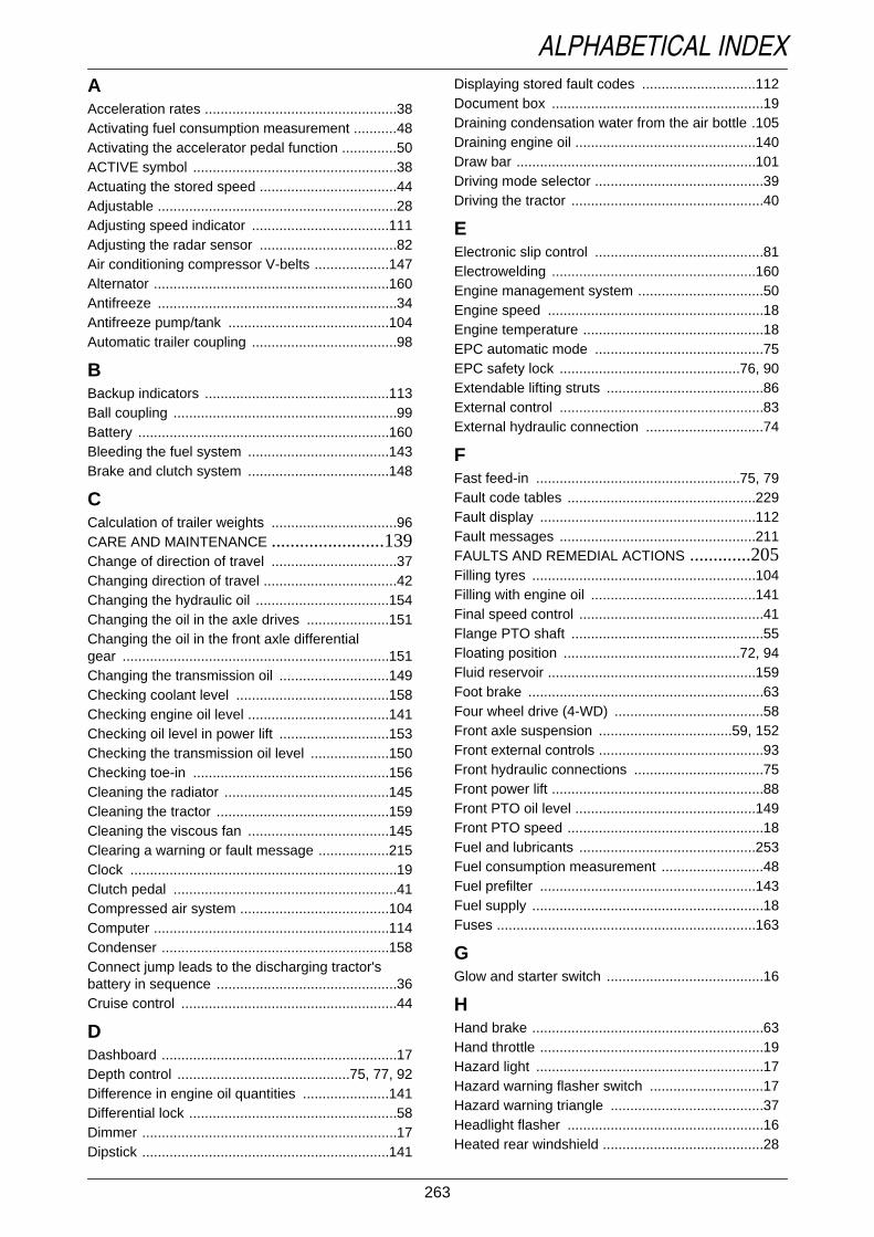
263
ALPHABETICAL INDEXAAcceleration rates .................................................38Activating fuel consumption measurement ...........48Activating the accelerator pedal function ..............50ACTIVE symbol ....................................................38Actuating the stored speed ...................................44Adjustable .............................................................28Adjusting speed indicator ...................................111Adjusting the radar sensor ...................................82Air conditioning compressor V-belts ...................147Alternator ............................................................160Antifreeze .............................................................34Antifreeze pump/tank .........................................104Automatic trailer coupling .....................................98
BBackup indicators ...............................................113Ball coupling .........................................................99Battery ................................................................160Bleeding the fuel system ....................................143Brake and clutch system ....................................148
CCalculation of trailer weights ................................96CARE AND MAINTENANCE ........................139Change of direction of travel ................................37Changing direction of travel ..................................42Changing the hydraulic oil ..................................154Changing the oil in the axle drives .....................151Changing the oil in the front axle differentialgear ....................................................................151Changing the transmission oil ............................149Checking coolant level .......................................158Checking engine oil level ....................................141Checking oil level in power lift ............................153Checking the transmission oil level ....................150Checking toe-in ..................................................156Cleaning the radiator ..........................................145Cleaning the tractor ............................................159Cleaning the viscous fan ....................................145Clearing a warning or fault message ..................215Clock ....................................................................19Clutch pedal .........................................................41Compressed air system ......................................104Computer ............................................................114Condenser ..........................................................158Connect jump leads to the discharging tractor'sbattery in sequence ..............................................36Cruise control .......................................................44
DDashboard ............................................................17Depth control ............................................75, 77, 92Difference in engine oil quantities ......................141Differential lock .....................................................58Dimmer .................................................................17Dipstick ...............................................................141
Displaying stored fault codes .............................112Document box ......................................................19Draining condensation water from the air bottle .105Draining engine oil ..............................................140Draw bar .............................................................101Driving mode selector ...........................................39Driving the tractor .................................................40
EElectronic slip control ...........................................81Electrowelding ....................................................160Engine management system ................................50Engine speed .......................................................18Engine temperature ..............................................18EPC automatic mode ...........................................75EPC safety lock ..............................................76, 90Extendable lifting struts ........................................86External control ....................................................83External hydraulic connection ..............................74
FFast feed-in ....................................................75, 79Fault code tables ................................................229Fault display .......................................................112Fault messages ..................................................211FAULTS AND REMEDIAL ACTIONS .............205Filling tyres .........................................................104Filling with engine oil ..........................................141Final speed control ...............................................41Flange PTO shaft .................................................55Floating position .............................................72, 94Fluid reservoir .....................................................159Foot brake ............................................................63Four wheel drive (4-WD) ......................................58Front axle suspension ..................................59, 152Front external controls ..........................................93Front hydraulic connections .................................75Front power lift ......................................................88Front PTO oil level ..............................................149Front PTO speed ..................................................18Fuel and lubricants .............................................253Fuel consumption measurement ..........................48Fuel prefilter .......................................................143Fuel supply ...........................................................18Fuses ..................................................................163
GGlow and starter switch ........................................16
HHand brake ...........................................................63Hand throttle .........................................................19Hazard light ..........................................................17Hazard warning flasher switch .............................17Hazard warning triangle .......................................37Headlight flasher ..................................................16Heated rear windshield .........................................28
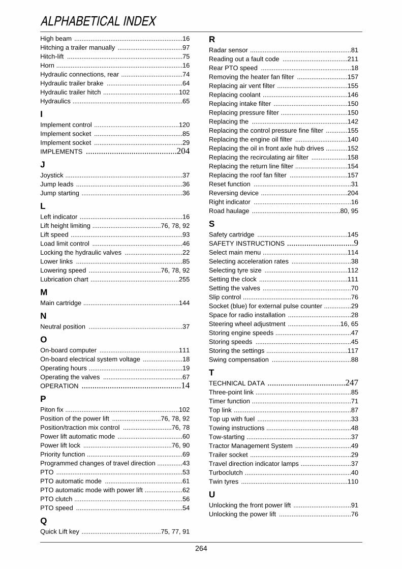
264
ALPHABETICAL INDEXHigh beam ............................................................16Hitching a trailer manually ....................................97Hitch-lift ................................................................75Horn ......................................................................16Hydraulic connections, rear ..................................74Hydraulic trailer brake ..........................................64Hydraulic trailer hitch ..........................................102Hydraulics .............................................................65
IImplement control ...............................................120Implement socket .................................................85Implement socket .................................................29IMPLEMENTS ..........................................204
JJoystick .................................................................37Jump leads ...........................................................36Jump starting ........................................................36
LLeft indicator .........................................................16Lift height limiting ......................................76, 78, 92Lift speed ..............................................................93Load limit control ..................................................46Locking the hydraulic valves ................................22Lower links ...........................................................85Lowering speed ........................................76, 78, 92Lubrication chart .................................................255
MMain cartridge .....................................................144
NNeutral position ....................................................37
OOn-board computer ............................................111On-board electrical system voltage ......................18Operating hours ....................................................19Operating the valves ............................................67OPERATION ..............................................14
PPiton fix ...............................................................102Position of the power lift ...........................76, 78, 92Position/traction mix control ...........................76, 78Power lift automatic mode ....................................60Power lift lock .................................................76, 90Priority function .....................................................69Programmed changes of travel direction ..............43PTO ......................................................................53PTO automatic mode ...........................................61PTO automatic mode with power lift .....................62PTO clutch ............................................................56PTO speed ...........................................................54
QQuick Lift key ............................................75, 77, 91
RRadar sensor ........................................................81Reading out a fault code ....................................211Rear PTO speed ..................................................18Removing the heater fan filter ............................157Replacing air vent filter .......................................155Replacing coolant ...............................................146Replacing intake filter .........................................150Replacing pressure filter .....................................150Replacing the .....................................................142Replacing the control pressure fine filter ............155Replacing the engine oil filter .............................140Replacing the oil in front axle hub drives ............152Replacing the recirculating air filter ....................158Replacing the return line filter .............................154Replacing the roof fan filter ................................157Reset function ......................................................31Reversing device ................................................204Right indicator ......................................................16Road haulage .................................................80, 95
SSafety cartridge ..................................................145SAFETY INSTRUCTIONS ...............................9Select main menu ...............................................114Selecting acceleration rates .................................38Selecting tyre size ..............................................112Setting the clock .................................................111Setting the valves .................................................70Slip control ............................................................76Socket (blue) for external pulse counter ...............29Space for radio installation ...................................28Steering wheel adjustment .............................16, 65Storing engine speeds ..........................................47Storing speeds .....................................................45Storing the settings .............................................117Swing compensation ............................................88
TTECHNICAL DATA ....................................247Three-point link .....................................................85Timer function .......................................................71Top link .................................................................87Top up with fuel ....................................................33Towing instructions ...............................................48Tow-starting ..........................................................37Tractor Management System ...............................49Trailer socket ........................................................29Travel direction indicator lamps ............................37Turboclutch ...........................................................40Twin tyres ...........................................................110
UUnlocking the front power lift ................................91Unlocking the power lift ........................................76

265
ALPHABETICAL INDEXVValve equipment ...................................................67Valve heating ........................................................69Variotronic Ti ......................................................126Variotronic Ti fault messages .............................223V-belt ..................................................................147V-belt tension .............................................147, 159Vehicle Identification Number .................................4Vibration damping ................................................80
WWarning beacon ...................................................28Warning light ........................................................38Warning messages .............................................205Wheel slip indicator ..............................................18Windshield washer system ...........................16, 159Windshield wipers ................................................16Winter fuel ............................................................34Work lamps ..........................................................28

266
ALPHABETICAL INDEX

Important information on service and maintenanceYour tractor will only perform to your complete satisfaction if you take good care of it from thevery start. Your Customer Service Centre will therefore prepare your tractor, free of charge, andinstruct you on how to operate and maintain it.
Protect your claims under Warranty by having all servicing carried out at the correct time by anauthorised FENDT service workshop!
After 50 operating hours (1st service)
After 500 operating hours (2nd service)
After 1000 operating hours (3rd service)
All subsequent maintenance will be carried out at our customer workshops by skilled technici-ans at reasonable cost and as indicated in the Maintenance Schedule of this Operating Manual.
To extend the life of the tractor, we recommend our annual Major Service, which includes an en-gine oil change, immediately after the main working season (e.g. the autumn).
During the initial 100 operating hours, it is not advisable to subject the tractor to extreme loads.
Every 100 operating hours, top up engine oil to the upper notch on the dipstick.
Make sure that only FENDT original parts are used for all services and repairs.
Unauthorised changes and modifications, and any damage resulting from rigidly mountedimplements (e.g. front loader) not purchased from FENDT, are not covered by the Warranty andare entirely at the owner's risk. This applies in particular to modifications to the power outputlimiter and maximum speed settings, and any damage as a result of exceeding the maximumpermissible loads and weights.
Services carried out according to the Maintenance Schedule:
50 operating hours 2000 operating hours 4500 operating hoursFirst service
Date and signature of mechanic Date and signature of mechanic Date and signature of mechanic500 operating hours 2500 operating hours 5000 operating hours
Second service
Date and signature of mechanic Date and signature of mechanic Date and signature of mechanic1000 operating hours 3000 operating hours 5500 operating hours
Third service
Date and signature of mechanic Date and signature of mechanic Date and signature of mechanic1500 operating hours 3500 operating hours 6000 operating hours
Date and signature of mechanic Date and signature of mechanic Date and signature of mechanic