Embed Size (px)
Citation preview
e v e r i t h i n g n e w e m e r g e s n o w
Operating Manual
EPPU-28-3000-1 ELECTRIC PLUNGER PUMPING UNIT
А Т . 6 8 7 4 5 2 . 0 7 4 O M

2 А Т . 6 8 7 4 5 2 . 0 7 4 O M
Dear Messrs,
Thank you for purchasing our equipment. We hope that out electric plunger pumping unit (hereinaf-ter referred to as EPPU) will be effectively used at your applications and will be of great benefit for you.
We also want to remind that this unit is a complex electrical and mechanical device, improper operation of which may lead to its failure. So we strongly recommend studying this Operating Manual carefully before proceeding to operation of this unit.
Set of documents supplied with the unit includes:- Operating Manual;- LMPSEM Certificate.- NPG Certificate.- VSD Certificate.- EPPU-28-3000-1 specification.This Operating Manual serves to make a user aware of the EPPU specifications, component parts,
principles of operation, operating and maintenance procedures.

3T R I O L C O R P O R A T I O N w w w . t r i o l c o r p . r u
Operating ManualContents
Contents
1.INTRODUCTION .......................................................................................4
2.INTENDED USE AND BRIEF DESCRIPTION ......................................................5
2.1. Intended use ............................................................................................................ 5
2.2. Specifications .......................................................................................................... 5
2.3 Submersible unit component parts and operation ........................................................ 7
2.4 Tools and accessories ............................................................................................... 9
3SAFETY PRECAUTIONS .............................................................................14
4EQUIPMENT PREPARATION AND WELL CONDITIONING ....................................15
5EQUIPMENT LAYOUT AT A WELL ..................................................................16
6RIGGING UP AND RUNNING SUBMERSIBLE UNIT INTO A WELL ...........................17
6.1 EPPU rigging-up ......................................................................................................17
7EPPU RUNNING INTO A WELL, ENSURING LEAKTIGHTNESS, TRIAL RUN ...............18
8UNIT STARTUP AND WELL DEVELOPMENT .....................................................19
9MAINTENANCE IN THE PROCESS OF OPERATION ............................................21
10EQUIPMENT PULLING-OUT AND DISMANTLING ............................................21
11TRANSPORTATION AND STORAGE ............................................................. 22
12INVESTIGATION OF CAUSES OF THE UNIT FAILURES WITHINWARRANTY PERIOD OF OPERATION ..................................................... 23
Appendix A(mandatory) .............................................................................. 24
Appendix B(optionally) ............................................................................... 25
4 А Т . 6 8 7 4 5 2 . 0 7 4 O M
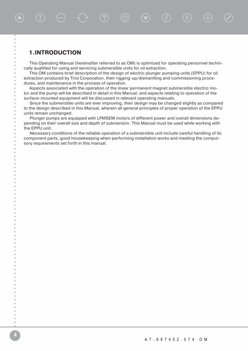
1.INTRODUCTION
This Operating Manual (hereinafter referred to as OM) is optimized for operating personnel techni-cally qualified for using and servicing submersible units for oil extraction.
This OM contains brief description of the design of electric plunger pumping units (EPPU) for oil extraction produced by Triol Corporation, their rigging-up/dismantling and commissioning proce-dures, and maintenance in the process of operation.
Aspects associated with the operation of the linear permanent magnet submersible electric mo-tor and the pump will be described in detail in this Manual; and aspects relating to operation of the surface-mounted equipment will be discussed in relevant operating manuals.
Since the submersible units are ever improving, their design may be changed slightly as compared to the design described in this Manual, wherein all general principles of proper operation of the EPPU units remain unchanged.
Plunger pumps are equipped with LPMSEM motors of different power and overall dimensions de-pending on their overall size and depth of submersion. This Manual must be used while working with the EPPU unit.
Necessary conditions of the reliable operation of a submersible unit include careful handling of its component parts, good housekeeping when performing installation works and meeting the compul-sory requirements set forth in this manual.

5T R I O L C O R P O R A T I O N w w w . t r i o l c o r p . r u
Operating Manual
2.INTENDED USE AND BRIEF DESCRIPTION
2.1. Intended use
Submersible units are designed for pumping stratum fluid out of oil wells.Stratum fluid is a mixture of oil, produced water and oil gas. It has the following characteristics:
• maximum fluid density is 1400 kg/m3;• maximum kinematic viscosity of a single-phase fluid at which the pump may operate without
any change in head and efficiency is 30 mm2/s;• produced water pH value is 4.2÷÷8.5 (this value may be decreased down to zero for no more
than 6 hours);• maximum content of produced water is 99 %; • Mohs’ micro-hardness of particles shall not exceed 7;• maximum concentration of H2S for conventional units is 0.01 g/l (0.001 %);• maximum concentration of aggressive components for corrosion-resistant units is as follows:
H2S – 1.25 g/l, CO2 – 1.15 g/l, Cl – 20 g/l, HCO3 – 1 g/l, and Ca2+ – 2 g/l;• temperature of the pumped-out fluid shall not exceed 150 °С;• maximum content of free gas at the pump suction side is up to 20 %.
Wells in which such units operate shall meet the following requirements:• maximum inner diameter of a well for each overall size of the unit shall correspond to thetech-
nical specification of pumps and submersible electric motors;• maximum deviation rate in the running-in area is 2° per 10 meters;• borehole deviation angle in the submersible unit operation area shall not exceed 40°.• maximum hydrostatic pressure in the unit operation region is 300 kgf/cm2.
2.2. Specifications
Table 2.1 EPPU specifications.
Parameter Value/description
Pump NPG-32-1200-1
Electric motor LPMSEM В-18-114
Variable-speed drive АК06-LL-400-110231-480 VSD, VSD for linear motor control
Telemetry No
Optional equipment Three-phase oil transformer of ACVOT type
Rated volume of extracted fluid at maximum setting depth and temperature of 70о С, m3/day
27.8
Maximum EPPU setting depth(with NPG32-1200-1 pump), m
3000
Number of strokes per cycle 1
Plunger speed of displacement, m/s 0 – 1.1
Number of poles in motor 304
Plunger greatest diameter, mm 32
Plunger displacement, mm 1200
Number of double strokes per minute up to 20
6 А Т . 6 8 7 4 5 2 . 0 7 4 O M
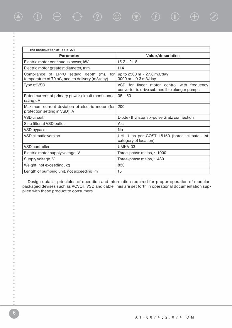
The continuation of Table 2.1
Parameter Value/description
Electric motor continuous power, kW 15.2 – 21.8
Electric motor greatest diameter, mm 114
Compliance of EPPU setting depth (m), for temperature of 70 оС, acc. to delivery (m3/day)
up to 2500 m - 27.8 m3/day3000 m - 9.3 m3/day
Type of VSD VSD for linear motor control with frequency converter to drive submersible plunger pumps
Rated current of primary power circuit (continuous rating), A
35 – 50
Maximum current deviation of electric motor (for protection setting in VSD), A
200
VSD circuit Diode- thyristor six-pulse Gratz connection
Sine filter at VSD outlet Yes
VSD bypass No
VSD climatic version UHL 1 as per GOST 15150 (boreal climate, 1st category of location)
VSD controller UMKA-03
Electric motor supply voltage, V Three-phase mains, ~ 1000
Supply voltage, V Three-phase mains, ~ 480
Weight, not exceeding, kg 830
Length of pumping unit, not exceeding, m 15
Design details, principles of operation and information required for proper operation of modular-packaged devises such as ACVOT, VSD and cable lines are set forth in operational documentation sup-plied with these product to consumers.

7T R I O L C O R P O R A T I O N w w w . t r i o l c o r p . r u
Operating Manual
2.3 Submersible unit component parts and operation
A single-stroke EPPU unit for oil extraction includes:• linear permanent magnet submersible electric motor (hereinafter referred to as LPMSEM);• submersible plunger pump (NPG);• three-phase oil transformer of ACVOT type (supplied separately);• cable line (supplied separately);• variable-speed drive (hereinafter referred to as VSD);• set of tools and accessories for rigging up the EPPU unit
Figure 2.1 – EPPU

8 А Т . 6 8 7 4 5 2 . 0 7 4 O M
The unit assembly is shown in Fig. 2.1The NPG unit drives LPMSEM and ensures supply of stratum fluid from a well into the pipeline at the
surface through the tubing string (hereinafter referred to as TS).LPMSEM is powered up from VSD through a transformer of ACVOT type.Cable line ensures a supply of electric energy to LPMSEM, and is connected to the said LPMSEM
by means of a cable gland. The cable is attached to NPG and TS using metal straps or cable protectors selected depending on the TS diameter, cable overall size and inner diameter of the casing string.
1. Tubing; 2. Valve unit; 3. Cable; 4. Pump; 5. Damper; 6. Filter; 7. Pump connection;
8. Linear motor.
Figure 2.2 – EPPU assembly
Surface-mounted electrical equipment, i.e. VSD and ACVOT, convert voltage of industrial network to a value ensuring optimum voltage across the LPMSEM input with due regard to the voltage drop in the cable, ensures control of the submersible unit operation and its protection in abnormal operating modes.
A set of tools and accessories helps to perform mounting/dismantling and RIH/POOH operations with the submersible unit in a well.
9T R I O L C O R P O R A T I O N w w w . t r i o l c o r p . r u
Operating Manual
2.4 Tools and accessories
A set of tools and accessories for EPPU rigging-up comprises the following basic items and materials:• pedestal for running in and pulling out units – 1 pc;• hanger – 1 pc;• multi-purpose single joint elevator or mounting single joint elevator – 2 pcs;• filling pump – 1 pc;• filling nozzle – 1 pc;• device for tightening straps – 1 pc;• device for pushing NPG plunger – 1 pc;• megohmmeter – 1 pc;• wrench 14 ÷17 – 1 pc;• wrench 17÷÷19 – 1 pc;• square wrench – 1 pc;• wrench for bleed nipple – 1 pc;• torque wrench with heads – 1 pc;• wrench for connecting LPMSEM rod with NPG plunger – 2 pcs;• hammer – 1 pc;• flat file – 1 pc;• feather-edge file – 1 pc;• round file – 1 pc;• mounting awl– 1 pc;• pliers – 1 pc;• screwdriver – 1 pc;• chisel – 1 pc;• knife – 1 pc;• Insulating gloves – 1 pc;• Protective goggles – 1 pc;• methyl alcohol – 0.2 l;• Unigerm-9 sealant – 0.05 kg.Pedestal (refer to Fig. 2.3) is designed for protecting the cable line against mechanical damages
during RIH/POOH operations. The pedestal makes it possible to conduct RIH/POOH operations with tubing string 73 mm in diameter.
10 А Т . 6 8 7 4 5 2 . 0 7 4 O M
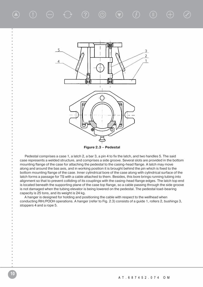
Figure 2.3 – Pedestal
Pedestal comprises a case 1, a latch 2, a bar 3, a pin 4 to fix the latch, and two handles 5. The said case represents a welded structure, and comprises a side groove. Several slots are provided in the bottom mounting flange of the case for attaching the pedestal to the casing-head flange. A latch may move along and around the bas axis, and in working position it is brought behind the pin which is fixed to the bottom mounting flange of the case. Inner cylindrical bore of the case along with cylindrical surface of the latch forms a passage for TS with a cable attached to them. Besides, this bore brings running tubing into alignment so that to prevent colliding of its couplings with the casing-head flange edges. The latch top end is located beneath the supporting plane of the case top flange, so a cable passing through the side groove is not damaged when the tubing elevator is being lowered on the pedestal. The pedestal load-bearing capacity is 25 tons, and its weight is 24 kg.
A hanger is designed for holding and positioning the cable with respect to the wellhead when conducting RIH/POOH operations. A hanger (refer to Fig. 2.3) consists of a guide 1, rollers 2, bushings 3, stoppers 4 and a rope 5.

11T R I O L C O R P O R A T I O N w w w . t r i o l c o r p . r u
Operating Manual
А-А
Figure 2.3 – Hanger
A guide is made as an arc-shaped frame consisting of two angle sections between which rollers and bushings are fixed. A cable being lowered or lifted is directed in a certain direction, and slides over rollers and bushings. Stoppers prevent a cable from accidental falling out of the guide. A rope serves to suspend a hanger from the hoisting unit mast. The hanger load-bearing capacity is 2 tons, and its weight is 20 kg.
Mounting single joint elevator is designed for pulling out, running in and hanging off or holding the entire unit on the casing-head flange.
Mounting single joint elevator (refer to Fig. 2.4) consists of a case 1, a latch 2, two pins 3 and two nuts 4. Pins may rotate about axes 5. A case represents an attachment clip with lugs welded to it, in which several ports for links and holes for studs 6 are provided. Inner surfaces of a case and a latch have a collar which enters a circular groove on the NPG head when elevator is closing.
Load-bearing capacity of a single joint elevator is 3 tons, and its weight is 12.5 kg.Instead of a mounting single joint elevator a multi-purpose single joint elevator of may be used, which
makes it possible to pull out, run in and hang off or hold any LPMSEM and NPG with a case diameter of 92 – 117 mm on the casing-head flange.
Load-bearing capacity of a single joint elevator of is 3 tons, and its weight is 14.5 kg.

12 А Т . 6 8 7 4 5 2 . 0 7 4 O M
Figure 2.4 – Mounting single joint elevator
Mounting single joint elevator is designed for pulling out, running in, hanging off or holding a LPMSEM on the casing-head flange. Mounting single joint elevator (refer to Fig. 7) consists of a case 1, a latch 2, a hinged bolt 3 and a nut 4. A latch may rotate about axis 5, and a hinged bolt may rotate about axis 6. A case represents an attachment clip with lugs, in which several ports for links and holes for studs 7 are provided. Inner surfaces of a case and a latch have rectangular projections, a distance between which is 105±0.5 mm. Load-bearing capacity of a single joint elevator is 2 tons, and its weight is 11 kg.
Figure 2.5 – Mounting single joint elevator

13T R I O L C O R P O R A T I O N w w w . t r i o l c o r p . r u
Operating Manual
A device for tightening straps is used in the process of running the EPPU unit to attach a cable line to NPG and TS using straps. The device shall be used as follows:
• wrap a product (NPG or TS) and cable with the strap not putting its end into the buckle;• push the device into the buckle with its slots facing the product, and insert the strap end into the
device slot, and then pull the device from the buckle holding it with a hand; • holding the strap on a cable with one hand, tighten the strap with another hand – using the • device as a lever and shifting the buckle along the device away from the handle – until the device
comes out from the buckle;• remove the strap from the device, and bend the free end down to the tightened strap by tapping.Megohmmeter is designed for measuring insulation resistance of electrical equipment of the pumping
unit in the process of its installation and operation.Other items of the set of tools and accessories are intended for conducting relevant operations in the
process of the EPPU mounting/dismantling.A set of tools and accessories is packed into a metal box ensuring safe-keeping and integrity of its
items during transportation and storage. It is supplied to a separate order.
14 А Т . 6 8 7 4 5 2 . 0 7 4 O M
3 SAFETY PRECAUTIONS
All activities associated with mounting and operation of the EPPU unit shall be done following the safe operation regulations set forth in the following labor safety regulations:
• Regulations for Operation of Hoisting Equipment;• Regulations for Operation of Consumers’ Electrical Installations;• Electric Safety Code;• Safety Rules for Operation of Customers’ Electrical Installations;• Safety Rules in Oil and Gas Industry РД 08-200-98;• Labor and Fire Safety Regulations.Electrical equipment of the unit shall be checked up and connected only by the personnel with at least
4th electrical safety qualification level.Checks of surface-mounted electrical equipment and other kinds of work admitting the possibility of
contacts with conductive parts shall be performed only when the equipment is switched off.Surface-mounted electrical equipment shall be reliable grounded. A ground loop shall be made using
busbars with a cross-section of at least 50 mm 2. The loop resistance shall not exceed 4 Ohm. A well shall be connected to a ground loop by busbars with a cross-section of at least 100 mm 2.
Operations with electrical equipment connected to the mains shall be conducted using personal protection equipment such as rubber insulating gloves, insulating stools, tools with insulated handles, etc.
When coupling LPMSEM and NPG with each other in the process of mounting it is strict-ly prohibited to manually connect the LPMSEM rod to the NPG plunger in the space between flanges/threads of LPMSEM and NPG cases.
When installing a single joint elevator on LPMSEM make sure that a collar of the elevator has surely entered the groove on the head, and the elevator latch is tightened by nuts.
It is not recommended to execute any installation work with the unit at the air temperatureс below - 30°С.Any well-site installation works are prohibited in the following cases:
• when the ambient temperature is below -30÷°С; but if a heat-insulated spulling device and well-head pad are available, such works may be executed until ultimate temperatures prescribed for RIH/POOH operations are reached;
• in case of atmospheric precipitation (rain, snow, dust-storm); but such installation works may be executed if a shelter for the well servicing and workover (WSWO) crew is provided which may protect the EPPU assemblies against precipitation;
• f the wind speed exceeds 11 m/s;• oil and gas blowouts at a well-site (also if the well flows; at gas outburst or breakthrough);• low light conditions at the work site (less than 100 lux);• oil contamination of the work site;• no cable roll (or its improper installationе), cable supports, automatic takeup at a well-site or other
deviations from the list of equipment pertinent to WSWO crews to be used for running EPPU units or placing/laying out crews’ equipment.
Before starting operations associated with the unit pulling out of a well it’s necessary to remove fluid from the tubing string using a bleedoff vale.
In the process of mounting/dismantling take care to ensure that tools and small items do not fall into a well as this may cause some troubles when running in or pulling out the unit.
In the course of mounting any sand or dirt on outer surfaces of NPG and LPMSEM as well as on inner surfaces of tubing is unacceptable.
15T R I O L C O R P O R A T I O N w w w . t r i o l c o r p . r u
Operating Manual
4 EQUIPMENT PREPARATION AND WELL CONDITIONING
Provided that rules of the equipment transportation and storage have been observed, an incoming inspection of the EPPU component parts produced by Triol Corporation needs not to be conducted by the Consumer before their shipping to a well-site. The Corporation guarantees normal operation of the equipment provided that installation and service regulations set forth in this Manual are observed.
However the Consumer in entitled to test any product within the scope of the RSI program set forth in relevant technical specifications.
Preparatory operations for the EPPU component parts to be conducted before rigging-up are described in this Manual.Parameters of the well and stratum fluid shall correspond to the EPPU service conditions specified in Section 2 of this Manual.The EPPU version suitable for a particular well, well operating practices and parameters of the surface-
mounted equipment shall be selected pursuant to a methodology adapted to the conditions of a particular oil deposit.
Operating mode of the unit shall be selected with due regard to ensuring pumping-out of the well-killing fluid during the well commissioning and supply of stratum fluid up to the booster pump
station at expected dynamic head, flowing tubing pressure and friction losses in TS and in-filed flow line.
To avoid troubles during running the EPPU into a well and its commissioning the following operations shall be conducted:
- flushing of production string and bottom-hole to remove corrosive liquids, dirt, sand, paraffin and any foreign objects;
- production string calipering: a caliper, which diameter is 3 – 4 mm less than the minimum well diameter specified in the LPMSEM and NPG technical specification, and which length is equal to that of the unit, shall be lowered to the depth exceeding the unit setting depth by 100 – 150 m.
If such a caliper does not pass or in case of drags the production string shall be reamed with a subsequent callipering.

16 А Т . 6 8 7 4 5 2 . 0 7 4 O M
5 EQUIPMENT LAYOUT AT A WELL
The EPPU delivery to the well shall be performed only using specially-equipped transport means, wherein all assemblies must be fastened by all means specified.
The EPPU handling operations at the well-site shall be performed jointly by the WSWO crew and a rigger from the ESU CMW (Central Maintenance Workshop for Electric Submersible Units) using hoisting devices and special machinery delivered the unit. The equipment shall be off-loaded by grasping it in two points while excluding impacts and drops.
LPMSEM and NPG shall be unloaded from the shipping boxes onto a special rack or pads with their heads facing the wellhead, and placed on supports (e.g. wooden pads) so that the distance from the LPMSEM or NPG end to the nearest support is equal to one-quarter of the NPG/LPMSEM length.
The EPPU assemblies shall be unloaded on the V-door ramp of WSWO crew cleaned from oil products and sand, and a drum with a cable shall be unloaded directly on the spulling device. If there is no access to the ramp or spulling device any mounting operations are prohibited.
Take care to preserve the EPPU assemblies and the cable from impacts and damages. Spulling device shall be located 15 – 20 m from the wellhead where viewable by the crew members. The cable shall run out from the drum top.
Supports for the cable about 1 m in height shall be spaced between the wellhead and the spulling device with the interval of 2 – 3 m to prevent the cable contacting the ground surface. The cable roll shall be suspended from the hoisting unit mast at the height of 9 – 10 m. Axes of rotation of the cable roll and drum shall be perpendicular to the line conventionally drawn from the wellhead to the drum, wherein the roll and drum centers shall be on this line.
VSD and transformer shall be installed and fixed on the foundation or base at the distance at least 20 m from the wellhead. Height of the foundations (bases) shall be such as to exclude any possibility of flooding and snowing of the equipment installed on them.
Drum with a cable shall be placed on a specially prepared flat level surface at the distance of 15 – 20 m from the wellhead, and installed on a power-driven cable-winding machine or supports on which the drum will rotate. The drum shall be located so that the axis of its rotation is perpendicular to the imaginary line drawn from the wellhead to the drum center. A cable shall be paid out from the drum top.
A hanger shall be suspended from the hoisting unit mast at the height of 12 – 15 m so that to be located away from the well axis facing the drum with a cable, wherein the hanger guide orientation shall coincide with the direction of the cable recovering. Then a cable shall be paid out the drum, and a flat cable shall be dragged through the hanger being directed on the rollers and bushings.
CAUTION! Prevent twisting of a flat cable! Prevent the cable contacting the ground!
Block-and-tackle system of the hoisting unit shall be aligned with respect to the wellhead.TS and relevant subs shall be prepared and placed on the rack or pads in such a way that the tubing
couplings face the wellhead, the tubing is within sight of the hoisting unit operator and does not hamper the handling of the cable. Outer and inner surfaces of the tubing must be clean.
17T R I O L C O R P O R A T I O N w w w . t r i o l c o r p . r u
Operating Manual
6 RIGGING UP AND RUNNING SUBMERSIBLE UNIT INTO A WELL
6.1 EPPU rigging-up
Rigging-up of a single-stroke EPPU unit shall be performed strictly in accordance with the relevant operating procedures.
1. Install a single joint elevator on the LPMSEM, lift it over the wellhead using a hanger and run into the well until the said elevator lands the casing-head flange.
2. Pay out the cable to the wellhead, drag it through the cable roll and lower to the LPMSEM cable outlet.
Caution! During pulling prevent bending of a cable with a bend radius less than 380 mm; prevent cable dragging on the ground.
3. Wash the LPMSEM cable ends with electrical insulating oil, clean them with a cloth, pull the ends apart and measure the insulation resistance using a 2500V megohmmeter. Discharge cable conductors after each measurement by grounding them instantaneously. Check up the integrity of cable conductors using a 1000V megohmmeter or low-voltage electric probe.
4. Splice a cable leaving the LPMSEM with the cable line using a special coupling.5. Measure the insulation resistance of the “cable – LPMSEM” system conductors with the help
of a 1000V megohmmeter. Discharge cable conductors by grounding them instantaneously upon completion of the measurement. Check up the integrity of the “cable – LPMSEM” system conductors using a 1000V megohmmeter or low-voltage electric probe. Make sure that the “cable – LPMSEM” system delta connection is available.
6. Remove the shipping cover from the LPMSEM head. In case the LPMSEM rod is deep inside the case it’s necessary to connect the LPMSEM to the VSD and pull the rod out of the motor case to the distance of about 30 cm above the LPMSEM head in manual control mode.
7. Make sure that the motor rod upstroke corresponds to the upstroke displayed on the VSD screen; and if not, interchange the motor connection phases and make this check once again until the rod upstroke corresponds to that displayed on the controller screen.
8. Disconnect the motor from the variable-speed drive.9. Install a single joint elevator on the NPG top at the distance about 30 cm from its upper head. Lift
the NPG over the well using a hanger and run it into the well so that the distance from the LPMSEM head to NPG is about 50 cm.
10. Remove the shipping cover from the NPG and pull the NPG extension piece out until it contacts the LPMSEM rod.
11. Degrease threads of the LPMSEM rod and NPG extension piece with alcohol. Apply the Unigerm-9 sealant (three droplets 3 mm in diameter spaced 120° apart), spec 6-01-1326-86, on the NPG extension piece thread near the 5th turn. Bring threads of the rod and extension piece into coincidence with each other, and connect the rod and extension piece using relevant special wrenches simultaneously rotating the NPG extension piece with the LPMSEM rod remained fixed. Tightening shall be performed with a torque of 10 ÷ 12 kgf∙m.
12. Run the NPG into the well until it engages with the LPMSEM end face. Running shall be performed carefully preventing damages of the sealing ring and studs. A cable shall be laid down into the NPG intake groove. Fasten the connection using nuts with spring washes (locking plates). Use a torque wrench for tightening. Nuts torque is 3.5 ÷ 4.5 kgf∙m. When using locking plates, nuts shall be fixed by unbending plates on the nut edges.
13. Fasten the submersible cable by steel strap (cable band) which is about 20 cm higher than the coupling connecting the NPG intake with the case.
14. Lift the LPMSEM+NPG assembly, remove the yoke clamp from the LPMSEM head and lower the assembly until a single joint elevator installed on the NPG top lands on the casing-head flange. In the process of running fasten the submersible cable by steel straps (cable bands) spaced along
18 А Т . 6 8 7 4 5 2 . 0 7 4 O M
the NPG length with the intervals of 0.5 m; wherein the “lock” of the fastening strap shall be located in “shadow” so that not to increase the pumping unit overall size.
15. Connect the first tubing joint to the NPG reducing coupling.The EPPU running into the well is further performed by a special team.
7 EPPU RUNNING INTO A WELL, ENSURING LEAKTIGHTNESS, TRIAL RUN
The EPPU running into the well, leak-proofing and trial run shall be performed in strict sequence specified below; and relevant operating procedures shall be followed at that.
1. Smoothly lift the EPPU unit, remove a single joint elevator, lay a flat cable along the NPG generating line and connect it using a cable band (steel strap) to the first tubing joint at the distance of 200-250 mm from the coupling.
2. Install a pedestal with opened latch onto the casing-head flange so that the tubing string is inside the inner cylindrical bore of the pedestal and the cable enters the side groove.
3. Align the pedestal bore to the inner cylindrical surface of the casing head, bolt the pedestal to the casing-head flange, and close the pedestal latch. Smoothly lower the EPPU unit until the tubing elevator lands on the pedestal. Drive in the next tubing joint and connect a cable to it with the help of a steel strap (cable band) at the distance of 200 – 250 mm from the coupling.
4. While connecting tubing joints and attaching a cable to them in a sequential order, run the EPPU unit into the well to the preset depth observing the following conditions:
• Float valve shall be installed over the third tubing joint or higher. Drain valve shall be installed on the next tubing joint; the drain screw insert proper shall be made of brass or cast iron, and sealed in the valve housing bore with a rubber ring.
• In locations where the cable line has a splice (somewhat thickened section where an extension piece is connected to the main cable), attach the cable to the tubing at the distance of 150 – 200mm above or below the splice. Do not locate a splice on the tubing coupling. If the splice location turns out to be on the coupling, replace the tubing joint by another one having different length.
• When attaching cable to the tubing string prevent its twisting in a spiral around the tubing joints in the process of their making-up and running-in.
• Pulling of the cable in the process of running-in shall be accomplished due to its own weight in the area between a hanger and the cable winding machine. Prevent slackening of the cable and its dragging on the ground. Cable bands shall be tightened up to the torque of the armour initial deformation. Buckle of the cable band shall be located in the free space between NPG and the cable but in no case on the cable surface; the cable band clinched end shall be firmly pressed to the buckle.
• Spinning of the EPPU unit and the tubing string in the process of running into the well is unacceptable; to avoid this the hook block of the hoisting unit shall be locked to prevent rotation.
• Running-in shall be performed smoothly with a speed not exceeding 0.25 m/s. In the course of running-in make sure to periodically check the alignment of the hoisting unit with respect to the wellhead; the EPPU running-in using non-aligned hoisting unit is prohibited.
• Measure the insulation resistance of the “cable – LPMSEM” system by a 1000V megohmmeter every 300 meters of the tubing string run in while recording the values in the data sheet. It shall be at least 5 Mohm. If the insulation resistance decreases below 5 Mohm, stop running in and wipe dry the cable; in case the resistance does not recover, call a representative of the ESU CMW who is authorized to finally decide if the running-in is still possible or the unit should be pulled out.
5. Remove the pedestal upon completion of the running-in.6. Upon completion of the running-in measure the LPMSEM insulation resistance (it shall be at least 5
Mohm) before and after leak-proofing of the gland inlet. 7. Free end of the cable armour shall be fastened under the nut of the wellhead fittings and tightened
19T R I O L C O R P O R A T I O N w w w . t r i o l c o r p . r u
Operating Manual
up. Lay the cable from the wellhead to the variable-speed drive. 8. Indicate a number of tubing joints run into the well and their setting depth (according to
measurements of the tubing) in the operational data sheet. 9. Call a representative of the ESU CMW and the oil production workshop to perform a trial run.10. In the course of the trial run conduct a pressure test of the lift up to the value of about 60 atm.
with the help of the NPG being in operation, check the leaktightness of the wellhead fittings and serviceability of the annulus float valve.
11. If no deviations are found the WSWO crew shall submit the filled-in operational data sheet of the EPPU unit to the oil production workshop (OPWS). The certificate shall be kept in the OPWS till the next workover and submission of a work plan to the WSWO crew with the purpose of pulling out this unit.
8 UNIT STARTUP AND WELL DEVELOPMENT
The EPPU startup, adjustment and run-up shall be performed in strict sequence specified below; and relevant operating procedures shall be followed at that.
1. Prepare and connect surface-mounted electrical equipment pursuant to its technical specifications and operating manuals. When using ACVOT and VSD use a cable with a cross-sectional area of at least 50 mm2 for their electrical connection to each other.
2. Connect a cable line extending from EPPU to ACVOT observing the following conditions:• marks on the cable line ends shall correspond to U, V and W marks on the terminals of • electrical equipment;• cable line ends to be brought into the ACVOT shall be stripped and unshielded; unshielded • section shall be long enough for the conductors to be pulled apart and connected to the terminals
of electrical equipment; armour end shall be grounded.• a cable extending from the well shall be laid on supports of at least 0.5 mm in height, wherein the
distance between these supports shall not exceed 3 m.3. Define the approximate required voltage at the ACVOT inlet (tap voltage) accounting for the voltage
loss in the cable line as per Appendix B (using UMKA controller).4. Set a voltage level for the transformer, which is the next higher than the rated voltage.5. Before starting the EPPU unit the following shall be checked:
• insulation resistance of the “cable – LPMSEM” system shall be at least 5 Mohm;• if ACVOT voltage is set properly;• if VSD functions properly in automatic mode with EPPU not connected;• if VSD protection set values are correct;• if other parameters of VSD are set correctly as per VSD Operating Manual;• if the cable cross-section corresponds to current loads;• fluid static level in the annulus;• if the surface-mounted Christmas tree is in good order and functions properly.
Test results shall be recorded in corresponding columns of the operational data sheet.6. Start up the EPPU unit following the relevant operating manuals for the surface-mounted electrical
equipment and VSD. 7. In case the overload protection is active when starting the EPPU unit, no more than two restarts
with the time interval of at least 2 ÷ 3 minutes are allowed. 8. The fluid level in the well as measured by echometer, the unit flow rate as per indications of the
measuring device, flowing tubing and annulus pressure, operating current and insulation resistance of the EPPU unit shall be continuously monitored in the course of starting-up. These parameters must be checked every 15 minutes over the run-up time.
9. After startup the EPPU unit shall operate for no more than one hour. At the same time a decrease of the annulus fluid level shall be monitored by echometer or other means preventing its decrease for no more than 200 m above the NPG intake (unless otherwise stipulated by the process flow

20 А Т . 6 8 7 4 5 2 . 0 7 4 O M
documentation).10. If the fluid level is not restored after the unit shutdown, the unit shall be restarted in 90 minutes.
Before starting, the electrical equipment protective devices shall be adjusted to the average value of operating current according to the data from the previous startup.
11. The unit shall operate once again for no more than one hour. Starts and stops shall be alternately repeated until the process of restoration of the fluid level in the well commences. In the course of the unit operation the LPMSEM operating current shall be monitored.
12. After the fluid level in the well starts restoring, start up the EPPU unit and watch the dynamic level. In case the level drops below 400 m (unless otherwise stipulated by the process flow documentation), decrease the number of the EPPU strokes per minute and keep monitoring the fluid level. By adjusting the number of strokes per minute a certain operation mode of the EPPU unit shall be achieved at which a dynamic level in the well will remain constant constituting at least 400 ÷ 600 m (unless otherwise stipulated by the process flow documentation).
13. The fluid pumping-out of the well shall be performed concurrently with the level restoration control until the “EPPU – well” system reaches operating conditions, i.e. until the delivery and dynamic level are constant at sufficient rate of the LPMSEM cooling.In steady-state mode the NPG shall be submersed at least 400 ÷ 600 meters below the dynamic level (unless otherwise stipulated by the process flow documentation). The NPG constant delivery and dynamic level indicate that the
“EPPU – well” system has reached operating conditions. 14. While bringing the well on to stable production the fluid level decrease down to the EPPU intake
shall be prevented. If less than 10 meters left to the NPG intake, the unit shall be shut down. 15. In the process of the unit running-up the delivery start time shall be controlled based on the values
specified in Table 8.1.
Table 8.1. Theoretic delivery start time for single-stroke EPPU (minutes).
Number of strokes per minute
Depth 2 4 6 8 10 12 14 16 18 20
1000 1017 509 339 254 203 170 145 127 113 102
1500 1526 763 509 381 305 254 218 191 170 153
2000 2035 1017 678 509 407 339 291 254 226 203
2500 2543 1272 848 636 509 424 363 318 283 254
3000 3052 1526 1017 763 610 509 436 381 339 305
Calculations have been made assuming that the NPG plunger diameter is 32 mm, plunger dis-placement is 1200 mm, and the string is composed of tubing 60 mm in diameter with the wall thickness of 5.0 mm.
16. After the unit has reached steady-state conditions its final adjustment for preventing overloads shall be performed, and the data obtained shall be recorded in the EPPU operational data sheet.
17. In case of a delay in the delivery commencement and a lower flow rate, check up the tubing string leaktightness and make sure there is a free passage though them. The EPPU lift shall be pressure tested with pressure not exceeding 60 kgf/cm2, in which case the pressure drop rate shall not exceed 10 kgf/cm2 per minute. To avoid any excess pressure during pressure testing a crew member shall be near the EPPU VSD, who will switch the EPPU off by operator’s command in case of a danger. Check up the leaktightness of the wellhead fittings and serviceability of the annulus float valve.
18. If the pressure drop rate exceeds specified values, or the flowing tubing head pressure does not increase, leaktightness of the assembly run into the well is defined with the help of surface-mounted devices. To execute such a work, connect the surface-mounted devices and pressure test the assembly through the tubing string. If complete leaktightness is not obtained, the EPPU and TS hang-er shall be pulled out until a leakage is revealed or pulled out completely.
21T R I O L C O R P O R A T I O N w w w . t r i o l c o r p . r u
Operating Manual
9 MAINTENANCE IN THE PROCESS OF OPERATION
In the process of the well operation by means of the EPPU unit the following parameters shall be monitored:
• amount of pumped out fluid;• content of produced water in pumping-out fluid and its pH value;• concentration of solids (total suspended solids – TSS) and Mohs’ micro-hardness;• content of hydrogen sulphide;• dynamic kevel;• flowing tubing pressure, annulus pressure and line pressure (if a telemetry system is available);• “cable – LPMSEM” system insulation resistance;• LPMSEM current;• supply voltage.The stratum fluid characteristics shall be measured once a month. Operating parameters of the unit and
well shall be checked at least once a week. Data on the unit operation shall be recorded in the operational data sheet.
The LPMSEM current in steady-state mode shall not exceed its rated value. The unit may be operated only in the modes permitted.
All stops of the EPPU unit and their causes shall be recorded in the operational data sheet. During stops a reliability of cables and external connections of the surface-mounted electrical
equipment shall be inspected.Preventive measures in relation to the surface-mounted electrical equipment shall be taken and
maintenance of such equipment shall be performed pursuant to its operating manuals.Emergency stops may take place in the course of the EPPU operation. In such a case the operating
personnel shall define causes of the stop, fix problems and start the unit or make a decision of its dismantling in accordance with the process procedures.
10 EQUIPMENT PULLING-OUT AND DISMANTLING
The EPPU unit shall be pulled out and dismantled in strict sequence specified below, in which case the relevant operating procedures shall be followed.
1. Arrange a hoisting unit at the wellhead and align its block-and-tackle system with respect to the wellhead.
2. Arrange a power-driven cable-winding machine or supports with the bare cable drum at the site in the same manner as before the rigging-up.
3. Fix a hanger on the hoisting unit mast.4. Prepare racks or pads on which the tubing and NPG component parts to be pulled out shall be laid,
and arrange them in the same manner as before the rigging-up.5. Prepare tools and accessories used for the LPMSEM and NPG rigging up and running in. Note that
shipping covers are provided for all submersible equipment and cable line.6. Disconnect the cable line, which has been used to apply electric energy to the EPPU unit, from the
surface-mounted electrical equipment, and bring its disconnected end thought the hanger towards the bare cable drum.
7. Dismantle the wellhead fittings. Lift the tubing string with EPPU, install and fix a pedestal on the casing-head flange.
8. Pull out the unit in the sequence reverse to that of the running-in process while observing the following conditions:
• While pulling the unit out of the well it should be kept in mind that it requires as careful and delicate handling as during pulling out; cable line shall be handled with extreme caution.
• In the process of pulling-out prevent rotation of the tubing string about its axis; remove steel straps (cable bands) from the cable as the tubing is pulled out of the well.

22 А Т . 6 8 7 4 5 2 . 0 7 4 O M
• Fix the cable-line end, which has been disconnected from the surface-mounted equipment, on the cable drum, whereupon take up the cable preventing its dragging on the ground.
• It is prohibited to pay the cable out on the ground. In the process of pulling-out inspect the cable thoroughly, reveal and mark all fault locations.
9. After some fluid appears in the tubing string, drop a metal bar inside, which will knock down the end of the bleed valve nipple; do not drop a metal bar inside empty tubing as it may put on high speed and damage the tubing string and the NPG float valve.
10. After the last tubing joint has been pulled out, remove the pedestal.11. Dismantle EPPU in the sequence reverse to that of the rigging-up process. At the same time bleed
all the fluid remained in the tubing sting, and then install shipping covers with new sealing rings.12. Dismantled NPG shall be placed on the racks or pads.13. Put the cover onto the LPMSEM head with new sealing ring.14. Disconnect LPMSEM from the mains. Measure and record the insulation resistance at voltage of
2500V.15. Measure and record the cable line insulation resistance at voltage of 5000V. Remove the cable-line
end from the hanger, wind it around the drum and fix there.16. Arrange LPMSEM on the racks or pads and remove a single joint elevator.17. Make a detailed visual examination of all the equipment pulled out, and record all damages and
faults detected. Retain sealing rings dismantled. Upon completion of dismantling record the 18. results of visual examination, measurements of insulation resistance of the cable and LPMSEM in
the operational data sheet.After the EPPU has been dismantled, its component parts shall be tested at the CMW test bench-es. If
the tests demonstrate positive results, the unit may be rerun into the well (without its disassembly at the shop) to return to service. A decision is made by the unit’s owner taking into account service conditions and hours in operation of the unit after the previous running-in.
If the tests demonstrate negative results, component parts of the unit are disassembled, flaws in parts and assemblies are detected and recorded, and their subsequent repair is carried out in accordance with the Consumer’s process flow documentation. Supplier’s warranty for the units pulled out at the Consumer’s discretion within the guarantee period of operation is canceled.
11 TRANSPORTATION AND STORAGE
NPG, LPMSEM and EPPU spare parts packed in shipping boxes may be transported by any means of transport provided that the Consumer shipping rules in force for each mode of transport are observed.
Loading and unloading of shipping boxed is performed by crane, in which case ropes with hooks shall be attached to four eye lugs available on the box.
LPMSEM and NPG may be transported uncased on specially equipped vehicles observing the rules for arrangement on pads, and provided that safety fastening that excludes any bending has been ensured.
The LPMSEM and NPG loading and unloading shall be performed by crane with the help of two ropes by wrapping them around. Ropes shall wrap the products at the distance of one quarter of the LPMSEM and NPG length from their ends.
LPMSEM and NPG shall be stored packed in shipping box or on racks excluding bending.EPPU may be stored at the ambient temperature from -50°С to +50°С under roof; outdoor storage is
also acceptable.A filling pump, tank with reserve electrical insulating oil and spare parts for EPPU shall be stored in a
warehouse at the temperature from 0°С to +40°С at the distance at least 1 m from heating appli-ances. Fabricated rubber products shall not be exposed to agents which may destroy them.
Transportation and storage of the surface-mounted electrical equipment shall be performed pursuant to their technical specifications and relevant operating manuals.
Drummed cable lines may be transported by any mode of transport provided that the Consumer shipping rules in force for each mode of transport are observed.
Drums shall be securely fastened on a transport vehicle so that to exclude any rolling or displacement. Loading and unloading of drums with cable lines shall be performed by crane, in which case a drum shall
23T R I O L C O R P O R A T I O N w w w . t r i o l c o r p . r u
Operating Manual
be caught only by its axle.Cable line shall be stored closed by a wooden mat, wherein a drum with the cable shall be placed on
a rigid pad excluding its rolling. It may be also stored outdoors at the ambient temperature from -50°С to +50°С but preferably it shall be stored under roof. When storing in a heated room, a cable line shall be located at least 1 m from heating appliances.
12 INVESTIGATION OF CAUSES OF THE UNIT FAILURES WITHINWARRANTY PERIOD OF OPERATION
If the EPPU unit fails within the warranty period of operation, any investigation of the fault causes shall be performed pursuant to the Consumer regulations in force. If in the course of the investigation a supposition is made that the failure is caused by poor workmanship of some unit assemblies, the Supplier shall be informed of the same and its representative shall be invited to joint revealing and clarifying the fault causes.
When investigating causes of the EPPU failure jointly by representatives of the Supplier and Consumer, the Consumer shall submit all documentation relating to the well and the unit, namely:
• well data sheet;• warranty certificate for the unit;• warranty certificates for two previous units, which had been in operation in this well;• plans, schedules, acts, reports of all kinds of work with the unit and surface-mounted equipment
executed at the well provided that operational data sheet is unavailable.A list of information to be included into the documentation is given in Appendix A. It is the Consumer
who is liable for the information validity. Besides, all component parts of the unit shall be submitted to the commission, namely LPMSEM, NPG, cable line and surface-mounted equipment. Based on the results of the submitted data analysis and inspection of the unit component parts, a conclusion of the EPPU fault causes shall be made and a corresponding bilateral act shall be drawn up.
No claim is admitted by the Supplier in case of improper selection of the unit not fitted for a particular well; in case of improper storage, transportation, rigging-up, operation and dismantling; and if incomplete information has been submitted.
If some defects in workmanship are revealed in the unit assemblies, the Supplier shall incur expenses only for replacement or repair of these particular faulty assemblies. Warranty liabilities for repaired or replaced items only cover the period of the unit operation not yet expired.
24 А Т . 6 8 7 4 5 2 . 0 7 4 O M
Appendix A(mandatory)
List of information to be submitted by the Consumer to the commission investigating the causes of the unit failures within the warranty period of operation:
1. Diameter and wall thickness of the casing. Borehole deviation in the area of the EPPUoperation.2. Results of the well killing operation (type of well-killing fluid, specific density, volume, and pH).3. Results of the well callipering; TS hazardous locations.4. Results of the well flushing-out.5. Results of the well tagging.6. Results of the TS pressure testing before the EPPU startup, when delivery is decreased or stopped.7. Characteristics of EPPU and surface-mounted equipment before delivery to the well-site (complete
set of supply, capacity, head, LPMSEM and cable insulation resistance, LPMSEM leaktightness, oil breakdown voltage, length of the unit).
8. EPPU conditions after rigging-up (LPMSEM and cable insulation resistance, results of the tubing string pressure testing).
9. The unit running-in and pulling-out speed.10. Results of check measurements of the “cable – LPMSEM” system insulation resistance every 300
meters of the tubing string run in when lowering the unit.11. Results of the EPPY inspection before starting (insulation resistance of the “cable – LPMSEM”
system, accuracy of voltage connection, serviceability of the VSD protection, phasing, automatic startup time after applying voltage).
12. Static fluid level in the annulus.13. Fluid level in the well after the unit has reached steady-state conditions, results of the dynamic
level time tracing. Results of check measurements of steady-state dynamic level, production rate, flowing tubing pressure, load current and supply voltage.
14. Results of the optimum supply voltage selection for LPMSEM, protection settings after two days of the unit operation.
15. All kinds of work done until steady-state conditions have been reached (shutdowns, power cutoff, changeovers, replacement of gates and valves) and its duration.
16. NPG setting depth, pumping capacity, thrust.17. Results of weekly measurements of load current, voltage, annular pressure, production rate and
dynamic level.18. Stratum fluid characteristics (content of mechanical impurities, micro-hardness of solids, water-cut,
content of free gas, hydrogen sulfide content and temperature).19. Information concerning the electrical power outage (causes and duration) and the work executed
by the cleanout crew.20. Results of the insulation resistance measurements for the “cable – LPMSEM” system; protection
parameters after repair of the mounted-surface equipment before the EPPU startup.21. Date and time of the EPPU startup, stop and pulling-out.22. Insulation resistance of the “cable – LPMSEM” system after the tubing string has been pulled out
(before the unit dismantling).23. Data on the cable mechanical damages.24. Check results after dismantling (appearance, cable and LPMSEM insulation resistance, oil
condition and its availability\in LPMSEM, LPMSEM leaktightness, availability of plugs).25. Results of disassembly and visual examination in CMW.26. Results of investigation of the causes of accidents with two previous units, which had been in
operation in this well.

25T R I O L C O R P O R A T I O N w w w . t r i o l c o r p . r u
Operating Manual
Appendix B(optionally)
Tap voltage calculationThis methodology describes algorithms of the ACVOT tap voltage calculation in AK06 Triol variable-
speed drives with UMKA-03 controllers.Calculation of the recommended tap shall be made by the following formulae:
where Urec
is recommended tap voltage;U
rate is rated tap voltage;
Ub is base voltage (maximum voltage at the VSD output allowing for losses in VSD), V;
Uloss
is voltage loss in the line from VSD to LPMSEM calculated by the following formula:
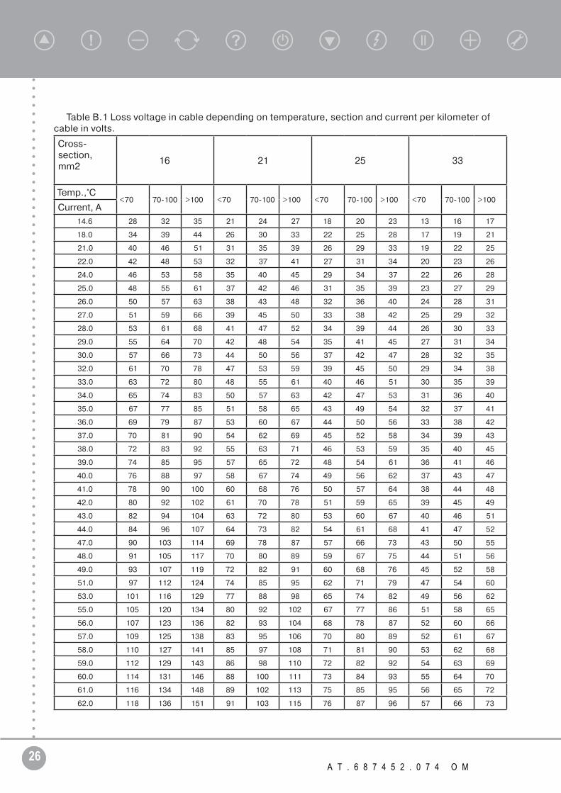
where Utab
loss
is loss voltage per kilometer depending on the current, wire section and stratum temperature ; H is LPMSEM setting depth, mValues are given in Table B.1.The nearest tap in the ACVOT is defined in accordance with the recommended tap.
26 А Т . 6 8 7 4 5 2 . 0 7 4 O M
Table B.1 Loss voltage in cable depending on temperature, section and current per kilometer of cable in volts.
Cross-section,mm2
16 21 25 33
Temp.,°С<70 70-100 >100 <70 70-100 >100 <70 70-100 >100 <70 70-100 >100
Current, A
14.6 28 32 35 21 24 27 18 20 23 13 16 17
18.0 34 39 44 26 30 33 22 25 28 17 19 21
21.0 40 46 51 31 35 39 26 29 33 19 22 25
22.0 42 48 53 32 37 41 27 31 34 20 23 26
24.0 46 53 58 35 40 45 29 34 37 22 26 28
25.0 48 55 61 37 42 46 31 35 39 23 27 29
26.0 50 57 63 38 43 48 32 36 40 24 28 31
27.0 51 59 66 39 45 50 33 38 42 25 29 32
28.0 53 61 68 41 47 52 34 39 44 26 30 33
29.0 55 64 70 42 48 54 35 41 45 27 31 34
30.0 57 66 73 44 50 56 37 42 47 28 32 35
32.0 61 70 78 47 53 59 39 45 50 29 34 38
33.0 63 72 80 48 55 61 40 46 51 30 35 39
34.0 65 74 83 50 57 63 42 47 53 31 36 40
35.0 67 77 85 51 58 65 43 49 54 32 37 41
36.0 69 79 87 53 60 67 44 50 56 33 38 42
37.0 70 81 90 54 62 69 45 52 58 34 39 43
38.0 72 83 92 55 63 71 46 53 59 35 40 45
39.0 74 85 95 57 65 72 48 54 61 36 41 46
40.0 76 88 97 58 67 74 49 56 62 37 43 47
41.0 78 90 100 60 68 76 50 57 64 38 44 48
42.0 80 92 102 61 70 78 51 59 65 39 45 49
43.0 82 94 104 63 72 80 53 60 67 40 46 51
44.0 84 96 107 64 73 82 54 61 68 41 47 52
47.0 90 103 114 69 78 87 57 66 73 43 50 55
48.0 91 105 117 70 80 89 59 67 75 44 51 56
49.0 93 107 119 72 82 91 60 68 76 45 52 58
51.0 97 112 124 74 85 95 62 71 79 47 54 60
53.0 101 116 129 77 88 98 65 74 82 49 56 62
55.0 105 120 134 80 92 102 67 77 86 51 58 65
56.0 107 123 136 82 93 104 68 78 87 52 60 66
57.0 109 125 138 83 95 106 70 80 89 52 61 67
58.0 110 127 141 85 97 108 71 81 90 53 62 68
59.0 112 129 143 86 98 110 72 82 92 54 63 69
60.0 114 131 146 88 100 111 73 84 93 55 64 70
61.0 116 134 148 89 102 113 75 85 95 56 65 72
62.0 118 136 151 91 103 115 76 87 96 57 66 73

27T R I O L C O R P O R A T I O N w w w . t r i o l c o r p . r u
Operating Manual
The continuation of Table B.1
Cross-section,mm2
16 21 25 33
Temp.,°С<70 70-100 >100 <70 70-100 >100 <70 70-100 >100 <70 70-100 >100
Current, A
63.0 120 138 153 92 105 117 77 88 98 58 67 74
64.0 122 140 155 93 107 119 78 89 100 59 68 75
65.0 124 142 158 95 108 121 79 91 101 60 69 76
67.0 128 147 163 98 112 124 82 94 104 62 71 79
69.0 131 151 168 101 115 128 84 96 107 64 73 81
72.0 137 158 175 105 120 134 88 101 112 66 77 85
73.5 140 161 179 107 123 137 90 103 114 68 78 86
77.5 148 170 188 113 129 144 95 108 121 71 82 91
78.5 150 172 191 115 131 146 96 110 122 72 83 92
81.0 154 177 197 118 135 150 99 113 126 75 86 95
82.0 156 180 199 120 137 152 100 115 128 75 87 96
86.5 165 189 210 126 144 161 106 121 135 80 92 102
88.0 168 193 214 129 147 163 108 123 137 81 94 103
90.5 172 198 220 132 151 168 111 126 141 83 96 106
98.0 187 215 238 143 163 182 120 137 152 90 104 115
99.0 189 217 240 145 165 184 121 138 154 91 105 116
104.0 198 228 253 152 173 193 127 145 162 96 111 122
131.0 250 287 318 191 218 243 160 183 204 121 139 154
178.0 339 390 432 260 297 331 218 249 277 164 189 209