Embed Size (px)
Citation preview

®
Guided Wave Radar
Level Transmitter
Installation and Operating Manual
™ 705software V3.x

2
UNPACKING
Unpack the instrument carefully. Make sure all componentshave been removed from the foam protection. Inspect allcomponents for damage. Report any concealed damage tothe carrier within 24 hours. Check the contents of the car-ton/crates against the packing slip and report any discrep-ancies to Magnetrol. Check the nameplate model numberto be sure it agrees with the packing slip and purchaseorder. Check and record the serial number for future refer-ence when ordering parts.
SPECIAL CONDITIONS FOR ATEX INTRINSICALLY SAFE USE
These units are in conformity with theprovisions of:1. The EMC Directive: 2004/108/EC.
The units have been tested to EN61326: 1997 + A1 + A2.
2. Directive 94/9/EC for Equipment or protective system foruse in potentially explosive atmospheres. EC-type exam-ination certificate number DEKRA99ATEX0518X (intrin-sic safe units) or BKI 12 ATEX 0017 (Ex d units) orKEMA99ATEX5014 (Non sparking units).
3. The PED directive 97/23/EC (pressure equipment direc-tive). Safety accessories per category IV module H1.
Amplifier nameplate:- partnumber- amplifier- serial n°- temperature/pressure- approval data
Probe nameplate- partnumber- serial number
00380344
IMPORTANT:To avoid damaging during transportation, Eclipse® 7MD/7ML large coax probes are shipped with 3 transport screws, securingthe inner antenna. The 3 screws have to be removed prior to installation. They are located nearby the process connection. Aseparate label is attached to draw the attention to remove the screws.
Because the enclosure of the Guided Wave Radar Level Transmitter Eclipse Model 705-5xxx-x1x and 705-5xxx-x7x and/orProbe Eclipse Model 7xx-xxx-xxx is made of aluminium, if it is mounted in an area where the use of category 1G apparatus isrequired, it must be installed such, that, even in the event of rare incidents, ignition sources due to impact and friction sparksare excluded.For applications in explosive atmospheres caused by combustible dust, gases, vapours or mists and where category 1G or 1Dapparatus is required, electrostatic charges on the non-metallic parts of the Probe Eclipse Model 7M5-xxx-xxx, Model 7M7-xxx-xxx and Model 7xF-xxx-xxx shall be avoided.

Size: 38 mm(1 1/2") oradjustablewrench
Customer supplied brackets are recommendedper each 3 m length. (Required for WGH § 19installations.)
Not important
min 25 mm (1")from tank bottom
3
Overfill safe and Overfill proofEclipse 7MD/7ML, 7MR/7MM and 7MT/7MN coaxial GWRprobes are “Overfill safe” in use and “Overfill proof” certified.Overfill safe means that the unit is capable to measure upto the process connection.Overfill proof protection (such as WHG or VLAREM) cer-tifies reliable operation when the transmitter is used asoverfill alarm but assumes that the installation is designedin such way that the vessel/ cage cannot overfill.Eclipse 7MS has a transitioning zone (zone in which the unitdoes not measure accurately) at the top. Maximum levelshould not be higher than 25 mm (1") up to 200 mm (8")(depending dielectrics - see probe specifications) below theprocess connection. This may include utilizing a nozzle orspool piece.Note: When using the 7MS probe, keep transmitter andprobe matched as a set.
Metallic (or any conductive) obstructions in the tanksMetallic obstructions have no influence on the measuringperformance of coaxial GWR probes.TurbulenceCustomer supplied mounting brackets are recommendedper each 3 m (10’) length and have no influence on the mea-suring performance of coaxial GWR probes.Stillwell /cagesCoaxial GWR probes are ideally suited for use in stillwellsor cages. There is no min. clearance allowance to be takeninto consideration.Shortening of probe lengthCoaxial GWR probes can be easily shortened on site whena procedure for this is strictly followed. This procedure canbe separately obtained from factory.
Size: 38 mm(1 1/2") oradjustablewrench
1/4" NPTpluggedflushingconnection
1/4" NPTpluggedflushingconnection
Customer supplied brackets are recommendedper each 3 m length. (Required for WGH § 19installations.)
Not important
min 25 mm (1")from tank bottom
MOUNTINGCoaxial type GWR probes(7MD - 7MR - 7MS - 7MT)
Note: The flushing connection allows to purge the inside ofthe coaxial probe without dismantling. Re-assure the use ofcompatible purging liquid/gas to avoid unwanted chemicalreaction.
Coaxial type GWR probes: Flushing connection(7ML - 7MM - 7MN)

4
MOUNTING
Overfill safe and Overfill proofEclipse twin rod GWR probes use software to ignore levelreadings in the transitioning zone at the top of the GWRprobe. The maximum level is a minimum of 150 mm (6")below the process connection. This may include utilizing anozzle or spool piece to raise the probe. Twin rod probesare overfill proof certified but not overfill safe in use.Eclipse twin cable GWR probes, used in media with lowdielectrics (hydrocarbons, powders) may require the settingof a blocking distance (zone in which the unit will not mea-sure) of 300 mm up to 500 mm (12" to 20") depending probelength. The longer the probe, the longer the blocking dis-tance will be. Eclipse twin cable GWR probes are not over-fill proof certified and not overfill safe in use.
Metallic (or any conductive) obstructions in the tanksObjects in the proximity within 25 mm (1") or closer such aspipes, support beams, metal ladders etc… may cause erro-neous readings.
Turbulence7MB: Customer supplied brackets are recommended pereach 3 m (10') length and have no influence on the mea-suring performance of 7MB GWR probes. Use the “off cen-ter” rod to fasten the brackets (see above drawings).7M5/7M7: It is recommended to secure the probe if signifi-cant turbulence exists. Optional weights are available tokeep the probe taught. The probe should not make any con-tact with the metal tank wall. The 7M7 (liquids) probe can beattached to the bottom of the tank – it is not recommendedto attach the 7M5 (solids) probe at the bottom of the tank.
Stillwell/cagesMin. 3" / DN 80 size nozzles, stillwells or by-pass cages arerequired for a good operation. Twin rod/cable probes shouldbe min 25 mm (1") away from any metal tank wall. 7M5/7M7have a 76 mm (3") inactive section. For nozzles < 3"/DN 80, this section should be flush with the bottom of thenozzle or extend into the vessel.
IMPORTANT:Twin rod/cable probes should be installed into a metal tank,stillwell or by-pass cage to meet CE requirements(EN 61326: 1997 + A1 + A2) electromagnetic compatibility.
Tank or cage wall
Off center rod
min 25(1)
Size: 47 mm(1 7/8") oradjustablewrench
min. 25 mm (1")from any metal
object
min 25 mm (1")from tank bottom
Use half open bracketsfor twin rod probes.
Twin rod (7MB) / Twin cable (7M5 - 7M7) GWR probes
For twin cable:min 25 mm(1") from anymetal object
Mounting considerations for 7MBNozzle should be DN80 (3") diameter or larger.
Mounting considerations for 7M5/7M7For nozzles < DN80 (3") diameter, the bottom of the inac-tive section of the probe should be flush with the bottom ofthe nozzle or extend into the vessel.

5
MOUNTING
13 mm Ø(0.50")
1
3
24
7M7/7M5 probe can be shortenedin field.a. raise the weight (1) to expose the two
securing devices (2)b. loosen the two #10-32 set screws (3)
on both securing devices using a2.5 mm (3/32") hex wrench and slidethe securing devices off of the probe
c. slide the TFE weight off of the probe.d.cut and remove the required cable (4)
lengthe. remove 90 mm (3 1/2") of the rib
between the two cablesf. strip 16 mm (5/8") of coating from the
two cables.g.slide the TFE weight back on to the
probe.h.enter new probe length (cm or inches)
in software (See page 12, Item 9)
Note: Probe can be attached to the tankbottom using the noose or the 13 mm Ø(0.50") hole provided in the TFE weight.7M7 GWR probes: cable tension shouldnot exceed 89 N7M5 GWR probes: pull down force shouldnot exceed 1360 kg (3000 lbs)
Twin rod (7MB) / Twin cable (7M5 - 7M7) GWR probes
Cage GWR probe (7MG)
Shortening of probe length7MB probes can be shortened safely in the field. Make sure to re-install the bottom spacer for proper alignment and to adaptthe probe length/ 4-20 mA settings in the menu.Twin cable probes can be safely shortened in the field using below procedure. Make sure to adapt the probe length / 4-20 mAsettings in the menu.
Vent
DrainCustomer or magnetrolsupplied cage/bridle or still well.
Ventingholes
Bottom spacer
Bottom spacer
For cage/still well:2": Ø 13 mm(0.50") rod
For cage/still wells:3": Ø 19 mm (0.75") tubing4": Ø 25 mm (1.00") tubing
Overfill safeAll 7MG GWR probes are overfill safe. Overfill safe meansthat the impedance match of the waveguide (probe) isaligned from electronics down to the bottom of the GWRprobe. This allows the Eclipse 705 to measure up to theprocess flange without any dead zone at the top of the GWRprobe.
Metallic (or any conductive) obstructions in the tanksMetallic obstructions have no influence on the measuringperformance of cage GWR probes.
Stillwell/cagesThe cage GWR probe is a single rod GWR probe whichuses an existing or new cage, bridle or schedule pipe still-well to re-create the same propagation of signal of a coaxi-al GWR probe. Cage GWR probes are suited for 2", 3" or 4"size diam. and use an impedance matching part that alignsin the same way with the characteristic impedance of a stan-dard coaxial style GWR probe.
Shortening of probe lengthCage GWR probes can be easily shortened on site. Alwaysre-install the bottom spacer and adapt the new probe lengthin the menu of the amplifier.

6
MOUNTING
Single rod (7MF - 7MJ) / Single cable (7M1 - 7M2) GWR probes
Size: 38 mm(1 1/2") oradjustablewrench
Size: 38 mm(1 1/2") oradjustablewrench
High Level shutdown and Overfill protectionSpecial consideration is necessary in any high level shut-down / overfill protection application where single rod GWRprobes are used. To ensure proper measurement, the guid-ed wave radar probe should be installed so the maximumoverfill level is at a minimum of 120 mm (4.8") up to910 mm (36") – blocking distance depending applicationbelow the process connection. Consult factory for furtherinformation.
Metallic (or any conductive) obstructions in the tanksObjects in the proximity of the probe may cause erroneousreadings.
TurbulenceThe bottom of the probe should be stabilized if turbulencewill cause a deflection of more than 75 mm at 3 m (3" at 10')of length. Optional bottom spacers in TFE (for 7MF) orPEEK (for 7MJ) should be used to stabilize the probe, incase turbulence exists. It is recommended to secure theprobe (7M1/7M2) if significant turbulence exists (see abovedrawing at right side). Optional weights are available tokeep the probe taught. The 7M1 (liquids) probe can beattached to the bottom of the tank – it is not recommendedto attach the 7M2 (solids) probe at the bottom of the tank.The probe should not make any contact with the metal tankwall.
Stillwell/cagesMax. 6” / DN 150 size stillwells or by-pass cages or a metaltank wall within 150 mm (6”) of the probe, will allow the unitto measure accurately in media with dielectrics down toεr 1,9.Nozzles do not restrict the performance by ensuring the fol-lowing:1. Nozzle must be 50 mm (2") or larger diameter.2. Nozzle inside diameter (A) should be ≥ to nozzle height
(B). If this is not the case, it is recommended to adjustBLOCKING DISTANCE and/or SENSITIVITY settings.
IMPORTANT:Single rod/cable probes should be installed into a metaltank, stillwell or by-pass cage to meet CE requirements(EN 61326: 1997 + A1 + A2) electromagnetic compatibility.When used in a non-metallic vessel flange (metal) mountingis recommended for optimal performance.
Distance to probe Acceptable objects< 150 mm (6") Continuous, smooth, parallel,
conductive surface (e.g. metaltank wall); probe should not touchtank wall
> 150 mm (6") < 1"/DN25 diameter pipe andbeams, ladder rungs
> 300 mm (12") < 3"/DN80 diameter pipe andbeams, concrete walls
> 450 mm (18") All remaining objects
Pipe reducersshould not be used
Correct installation
AB

7
MOUNTING
Shortening of probe lengthSingle rod/cable probes can be shortened safely in the field. Make sure to adapt the probe length/ 4-20 mA settings in the menuand the re-install of a bottom spacer when applicable.Single cable probes can be safely shortened in the field using below procedure. Make sure to adapt the probe length/ 4-20 mAsettings in the menu.
13 mm Ø(0.50")
1
2 3
4
7M1/7M2 probe can be shortened infield.a. raise TFE weight (1) exposing secur-
ing device (2)b. loosen both #10-32 set screws (3)
using 2.5 mm (3/32") hex wrenchand remove securing device
c. cut and remove needed cable length(4)
d. re-attach securing device (2) andtighten screws
e.enter new probe length (cm or inch-es) in software (See page 12, Item 9)
13 mm Ø(0.50")
Note: Probe can be attached to the tankbottom using the noose or the 13 mm Ø(0.50") hole provided in the TFE weight.7M1 GWR probes: cable tension shouldnot exceed 89 N (20 lbs).7M2 GWR probes: pull down forceshould not exceed 1360 kg (3000 lbs)
Single rod (7MF - 7MJ) / Single cable GWR probes
Overfill safe and Overfill proofEclipse 7EK GWR probes are “Overfill safe” in use and“Overfill proof” certified.Overfill safe means that the unit is capable to measure upto the process connection. Units with “non overfill safe”probes use software to ignore level readings in the block-ing distance or transitioning zone. When level rises too highin this zone, the unit may consider the end of probe reflec-tion as the real level and may report an empty vesselinstead of an overfilling vessel.Overfill proof protection (such as WHG or VLAREM) cer-tifies reliable operation when the transmitter is used asoverfill alarm but assumes that the installation is designedin such way that the vessel/cage cannot overfill.The 7EK probe is designed to replace without modificationtop/bottom mounted displacer transmitters. The unit willmeasure over the entire probe length and indicate for20.5 mA above the highest measurable point and 3.8 belowthe lowest measurable point.
Top/Bottom GWR probes(7EK)
1 1/2" or 2"socket weld orNPT
1 1/2" or 2"Flanged

8
MOUNTING
Do not insulate thehigh frequency connector
in case of high temperatureapplications
Insulation
WRONG GOOD
Max +150 °C (+300 °F)Max +100 °C (+212 °F) for Ex d unit
On high or low temperature applications, install a ventedprotection around the probe/housing.
360° rotatable: Position foroptimum wiring/viewing
Max. rotation 270°
Size: 38 mm (1 1/2") oradjustable wrenchRecommended torque 60 Nm(45 ft-lbs)
Remove protection
Removeprotection
CAUTION: be careful not to bend or dirty the gold, high frequencymale connector (a) and its female connector (b). Clean with iso-propyl alcohol and cotton swabs, if necessary
(a)
(b)
Transmitter
IntegralRemote

9
WIRING
CAUTION: power must be switched OFF before wiring the unit.
– +
IS
®
–LOOP
CURRENT
IS
0 % 100 %
Positive supply to (+) terminal/HART connectionNegative supply to (-) terminal/HART connectionmin. 11 V DC requiredmax 28,4 V DC – ATEX intrinsically safemax 36 V DC – all other versions
Shield wire to green grounding screw (resistance toground must be < 1 Ω).
Standard shielded twistedpair cable (recommendedbut not needed when wiredas per NAMUR NE 21 forfield strenghts up to10 V/m).
Use certified flameproof cablegland(s) and cable for Explosionproof area.
Currentloop testpoint
Galvanic Barrier:Only needed for intrinsically safe units:max 28,4 V DC @ 94 mA
ANALOG I/Oor
DIGITAL I/O(only for units with HART)
Customer suppliedlocal current meter
Do not connect shield
ExNon Ex
ExNon Ex
ExNon Ex
IMPORTANT:The shield wire should only be grounded at ONE side only. It is recommended to connect the shield to ground in the field (atthe transmitter side - as shown above) but connecting in the control room is also allowed.
LOOP RESISTANCE
1200
1000
800
600
400
200
00 10 20 30 40 Vdc
20,5 mA
24 Vdc
630
11
Ω

10
Display Action Comment
Units!cm
Unitscm
Units!cm
CONFIGURATION
NOTE: When connected to an approved barrier, the intrinsically safe electronics of the Eclipse allow to remove thecovers with power switched on – even if the area is known to be hazardous
2 line – 8 characters LCDDefault display cycles every 5 s through Status «STATUS» / Level «LEVEL»/ % output «% OUTPUT» / Loop «LOOP».
Up/Down and Enter pushbuttons
IMPORTANT: The Eclipse amplifier can be bench configured without GWRprobe connected. Ignore the start up message «No Level Signal» /«STATUS» / «WeakSgnl» in this case.
Press : The last character on the first line of the display changes to «!». This sign con-firms that the values/choices of the second line can be modified via the andpush buttons.
Press * Scroll through the choices or increase/decrease the values on the second lineof the display by and pushbuttons.
* Accept values/choices as selected by pushbutton.
Press Scroll through the menu.
PASSWORD
DISPLAY ACTION COMMENT
Ent Pass0
New Pass4096
Ent Pass!1
NOTE: Password protection is activated when after 5 minutes no keystrokes are sensed.
Display shows «0» Factory default settingData is not protected
Press and last character changes into «!»Enter your personal password with and(any value between 1 and 255)Press to confirm
Setting password
Press and enter old passwordPress and last character changes into «!»Enter your new password with and(any value between 1 and 255)Press to confirm
Changing password
Display shows an encrypted value, enter your passwordor call Magnetrol for assistance to recoop your passwordif necessary
Data is protected by a validPassword

11
20 mA Level(100%-point)
Referencepoint
Probe TypeProbe
Length
Offset
SafetyZone
Inch or cm
Dielectricof medium
Blockingdistance
4 mA Level(0%-point)
TERMINOLOGY
BEFORE STARTING
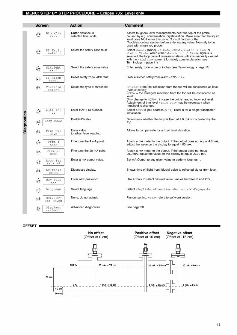
Offset = cm or inchesThe offset is the distance between reference point (e.g.bottom of tank) and end of probe. From the reference pointboth 4 mA and 20 mA levels are calibrated. When offset isset at zero, the end of the probe is the reference point.
4 mA Level = cm or inchesor zero level point, is measured from the reference point.The unit has a transition zone at the bottom of the probe.Min. level to enter for media with:εr = 2.0: 150 mm (6") + Offsetεr = 80: 25 mm (1") + Offset
20 mA Level = cm or inchesor 100 % level point, is measured from the reference point.The unit has a transition zone at the top of the probe.Transition zone varies depending on probe type andmedia: see probe specifications page 33, up to 37.
Probe length = cm or inches, record the exact probe length asprinted on the nameplate: 705-xxxx-xxx / 7Mx-xxx-xxx
Dielectric Select the dielectric scale of the media to measure:1.4–1.7 or 1.7–3 or 3–10 or 10–100. When the dielectric isknown, it will enhance the overall accuracy of the unit butselect the dielectric scale ALWAYS to the lowest expecteddielectricum.
CONFIGURATION
Start from run mode:1. Select the desired language for configuration: English, French, German or Spanish in the language screen (32)
«language». Scroll up for quickly reaching the language selection screen.2. Define type of measurement:
a. Level only (pages 12 & 13)b. Level and Volume (pages 14 & 15)c. Interface only (pages 16 & 17)d. Interface and Volume (pages 18 & 19)Scroll down until the screen reads «MeasType». The unit will now show only the applicable screens for the selected typeof measurement.
3. Scroll one screen down and select the applicable engineering unit in «LvlUnits», all configuration values will be enteredin that engineering unit.
4. Move to the loop control screen «LoopCtrl», select the loop control in function of the type of measurement «MeasType»selected.
5. Refer to the configuration procedure of the selected type of measurement.6. Refer to page 20 for all hidden diagnostic screens and advanced configuration parameters. These screens allow the
advanced user to configure the unit for special applications or to troubleshoot the unit in the field. It is NOT recommendedto access this toolset without proper guidance or having followed proper training.
No offset(Offset at 0 cm)
Positive offset(Offset at 10 cm)
Negative offset(Offset at -15 cm)
75 cm
100 %
0 %15 cm10 cm
20 mA = 75 cm
4 mA = 15 cm
20 mA = 85 cm
4 mA = 25 cm
20 mA = 60 cm
4 mA = 0 cm
Safety zone: In addition to the blocking distance,the user can introduce a safety zoneto warn for liquid level entering thiszone beneath the blocking distance.The loop signal will shift in this zoneto a selectable fault signal. The unitwill go to normal read out, when leveldrops lower than the safety zone,unless a latched fault signal is used.The safety zone is disabled from fac-tory. Safety zone related settingsinclude:«SZ Fault»: to select the preferrederror signal«SZ Height»: to define the safetyzone area«SZ Alarm Reset»: to manuallyreset a latched «SZ Fault»

12
= Quick Start up
MENU: STEP BY STEP PROCEDURE – Eclipse 705: Level only
Screen Action CommentRu
nm
ode
Confi
gura
tion
1
2
3
4
7
10
12
13
16
17
*Status**Level*
*%Output**Loop*
Levelxx.x
%Outputxx.x%
Loopxx.xx mA
5 PrbModel(select)
MeasType(select)
6 PrbMount(select)
9 Probe Lnxxx.x
8 LvlUnits(select)
Lvl Ofstxxx.x
11 Dielctrc(Select)
Senstvtyxxx
Loop Ctrl(Select)
14 Set 4mAxxx.x
Dampingxx sec
15 Set 20mAxxx.x
Fault(Select)
Transmitter Display Transmitter default values cycle every 5 seconds. Status «Status»,Level «Level», % Output «% Output», and Loop «Loop».
Transmitter Display Transmitter displays level value in selected engineering units.
Transmitter Display Transmitter displays % Output measurement derived from 20 mAspan.
Transmitter Display Transmitter displays Loop measurement (mA).
Select the type of probe Select as per the 3 first digits of the probe partnumber. The partnumberis shown on the nameplate: e.g. 705-510A-A11/7MT-A230-218, select7xT-x from the list.
Select the type of probemounting.
Select NPT «NPT», BSP «BSP» or Flange «Flange». (consult facto-ry when a «7xK» GWR probe is used)
Select the type of measurement Select level «Levl Only».
Select units for level cm «cm», m «m», inches «inches» or feet «feet».
Enter the exact length ofprobe.
Enter as per the 3 last digits of the probe partnumber on the nameplate:- rigid probes, enter value cm or inches,- flexible probes, enter value in meters or feete.g. 705-510A-A11/7MR-A230-218, enter «218» cm probe length.
Enter the offset value. When entering configuration values from the end of the probe iscumbersome, an offset can be introduced to determine a newreference point. This reference point can be either below theprobe (positive offset) or at the probe (negative offset). See page11 “Terminology”.
Enter the dielectric rangevalue of the media
Select: «1.4–1.7»; «1.7–3»; «3–10» or «10–100»«1.7–3» is recommended for dielectrics ≥ 1,7
Enter sensitivity value Allows fine adjustment of internal gain.
Select primary variable (PV) Primary variable is the loop controlling parameter. Select level«Lvl only»
Enter the level valuefor the 4 mA point.
A transition zone may exist at the bottom of the probe. See FunctionalSpecifications Probe, see pages 33 up to 37.
Enter the level valuefor the 20 mA point.
A transition zone / blocking distance may exist at the top of the probe.See Functional Specifications Probe, see pages 33 up to 37.
Enter the damping factor. A Damping factor (1-10 seconds) may be added to smooth a noisydisplay and/or output due to turbulence.
Enter the value for error. Select «3.6 mA», «22 mA» or hold last value «HOLD». In case ofloop failure, error signal will follow the failing trend; meaning the unitwill show 3.6 mA when the reviewed loop current by the device isfound too low. The unit will show 22 mA in case the reviewed loopcurrent is found too high.
13
MENU: STEP BY STEP PROCEDURE – Eclipse 705: Level only
Screen Action CommentDi
agno
stic
s 23
26
27
28
29
30
Poll Adrxx
Trim 4xxxx
25 Trim Lvlxx.x
24 Loop Mode
Trim 20xxxx
Loop Tstxx.x mA
LvlTicksxxxxx
New Passxxx
31
32
Language
Mdl705HTVer xx.xx
33 DispFact(select)
18
19
20
21
22
BlockDisxx.x
SZ Fault(select)
SZHeightxx.x
SZ AlarmReset
Threshld(select)
Enter distance inselected level units
Allows to ignore level measurements near the top of the probe,caused by e.g. condensation, crystalization. Make sure that the liquidlevel does NOT enter this zone. Consult factory or the‘Troubleshooting’ section before entering any value. Normaly to beused with single rod probe.
Select the safety zone fault. Select «None» (None), «3.6mA», «22mA», «Latch 3.6mA» or«Latch 22mA». When either «Latch 3.6 / 22mA» signals isselected, the loop current remains in alarm until it is manually clearedwith the «SZAlarm» screen ( for safety zone explanation seeTerminology - page 11).
Select the safety zone value Enter safety zone in cm or inches (see Terminology - page 11).
Reset safety zone latch fault Clear a latched safety zone alarm «SZFault».
Select the type of threshold «Fixed» = the first reflection from the top will be considered as level(default setting)«CFD» = the strongest reflection from the top will be considered aslevel.Only change to «CFD», in case the unit is reading incorrect level.Adjustment of trim level «Trim Lvl» may be necessary whenthreshold is changed.
Enter HART ID number. Select a HART poll address (0-15). Enter 0 for a single transmitterinstallation.
Enable/Disable Determines whether the loop is fixed at 4.0 mA or controlled by thePV.
Enter valueto adjust level reading.
Allows to compensate for a fixed level deviation.
Fine tune the 4 mA point. Attach a mA meter to the output. If the output does not equal 4.0 mA,adjust the value on the display to equal 4.00 mA.
Fine tune the 20 mA point. Attach a mA meter to the output. If the output does not equal20.0 mA, adjust the value on the display to equal 20.00 mA.
Enter a mA output value. Set mA Output to any given value to perform loop test .
Diagnostic display. Shows time of flight from fiducial pulse to reflected signal from level.
Enter new password. Use arrows to select desired value. Values between 0 and 255.
Select language Select «English», «Français», «Deutsch» or «Espagnol».
None, do not adjust. Factory setting. «Ver» refers to software version.
Advanced diagnostics. See page 20.
No offset(Offset at 0 cm)
Positive offset(Offset at 10 cm)
Negative offset(Offset at -15 cm)
75 cm
100 %
0 %15 cm10 cm
20 mA = 75 cm
4 mA = 15 cm
20 mA = 85 cm
4 mA = 25 cm
20 mA = 60 cm
4 mA = 0 cm
OFFSET

14
= Quick Start up
MENU: STEP BY STEP PROCEDURE – Eclipse 705: Level & Volume
Screen Action CommentRu
nm
ode
Confi
gura
tion
1
2
3
4
8
11
12
13
19
20
*Status**Volume**%Output**Loop*
Volumexxx
%Outputxx.x%
Loopxx.xx mA
5 Levelxxx
MeasType(select)
7 PrbMount(select)
6 PrbModel(select)
10 Probe Lnxxx.x
9 LvlUnits(select)
Lvl Ofstxxx.x
14 Dielctrc(Select)
VolUnits(select)
StrapTblxx pnts
17 Set 4mAxxx.x
Dampingxx sec
18 Set 20mAxxx.x
15 Senstvtyxxx
16 Loop Ctrl(Select)
Fault(Select)
Transmitter Display Transmitter default values cycle every 5 seconds. Status «Status»,Volume «Volume», % Output «% Output», and Loop «Loop».
Transmitter Display Transmitter displays Volume Value in selected engineering units.
Transmitter Display Transmitter displays % Output measurement derived from 20 mAspan.
Transmitter Display Transmitter displays Loop measurement (mA).
Transmitter Display Transmitter displays level in selected volume units «LvlUnits».
Select the type of probe Select as per the 3 first digits of the probe partnumber. The partnumberis shown on the nameplate: e.g. 705-510A-A11/7MT-A230-218, select7xT-x from the list.
Select the type of probemounting.
Select NPT «NPT», BSP «BSP» or Flange «Flange». (consult facto-ry when a «7xK» GWR probe is used)
Select the type of measurement Select level and volume «Lvl&Vol».
Select units for level cm «cm», m «m», inches «inches» or feet «feet».
Enter the exact length ofprobe.
Enter as per the 3 last digits of the probe partnumber on the nameplate:- rigid probes, enter value cm or inches,- flexible probes, enter value in meters or feete.g. 705-510A-A11/7MR-A230-218, enter «218» cm probe length.
Enter the offset value. When entering configuration values from the end of the probe iscumbersome, an offset can be introduced to determine a newreference point. This reference point can be either below theprobe (positive offset) or at the probe (negative offset). See page11 “Terminology”.
Select units for volume Liters «l» or gallons «g».
Enter level/volumepairs in max 20 steps
Liters «l» or gallons «g».
Enter the dielectric rangevalue of the media
Select: «1.4–1.7»; «1.7–3»; «3–10» or «10–100»«1.7–3» is recommended for dielectrics ≥ 1,7
Enter sensitivity value Allows fine adjustment of internal gain.
Select primary variable (PV) Primary variable is the loop controlling parameter. Select level«Lvl only» or volume «volume»
Enter the level valuefor the 4 mA point.
A transition zone may exist at the bottom of the probe. See FunctionalSpecifications Probe, see page 33 up to 37.
Enter the level valuefor the 20 mA point.
A transition zone / blocking distance may exist at the top of the probe.See Functional Specifications Probe, see page 33 up to 37.
Enter the damping factor. A damping factor (1-10 seconds) may be added to smooth a noisydisplay and/or output due to turbulence.
Enter the value for error. Select «3.6 mA», «22 mA» or hold last value «HOLD». In case ofloop failure, error signal will follow the failing trend; meaning the unitwill show 3.6 mA when the reviewed loop current by the device isfound too low. The unit will show 22 mA in case the reviewed loopcurrent is found too high.
15
MENU: STEP BY STEP PROCEDURE – Eclipse 705: Level & Volume
Screen Action CommentDi
agno
stic
s 26
29
30
31
32
33
Poll Adrxx
Trim 4xxxx
28 Trim Lvlxx.x
27 Loop Mode
Trim 20xxxx
Loop Tstxx.x mA
LvlTicksxxxxx
New Passxxx
34
35
Language
Mdl705HTVer xx.xx
21
22
23
24
25
BlockDisx.x
SZ Fault(select)
SZHeightxx.x
SZ AlarmReset
Threshld(select)
Enter distance inselected level units
Allows to ignore level measurements near the top of the probe,caused by e.g. condensation, crystalization. Make sure that the liquidlevel does NOT enter this zone. Consult factory or the‘Troubleshooting’ section before entering any value. Normaly to beused with single rod probe.
Select the safety zone fault. Select «None» (None), «3.6mA», «22mA», «Latch 3.6mA» or«Latch 22mA». When either «Latch 3.6 / 22mA» signals isselected, the loop current remains in alarm until it is manually resetwith the «SZAlarm» reset screen ( for safety zone explanation seeTerminology - page 11).
Select the safety zone value Enter safety zone in cm or inches (see Terminology - page 11).
Reset safety zone latch fault Select «Reset» «No» or «Yes» to reset alam when either «Latch3.6mA» or «Latch 22mA» was selected in «SZFault».
Select the type of threshold «Fixed» = the first reflection from the top will be considered as level(default setting)«CFD» = the strongest reflection from the top will be considered aslevel.Only change to «CFD», in case the unit is reading incorrect level.Adjustment of trim level «Trim Lvl» may be necessary whenthreshold is changed.
Enter HART ID number. Select a HART poll address (0-15). Enter 0 for a single transmitterinstallation.
Enable/Disable Determines whether the loop is fixed at 4.0 mA or controlled by thePV.
Enter valueto adjust level reading.
Allows to compensate for a fixed level deviation.
Fine tune the 4 mA point. Attach a mA meter to the output. If the output does not equal 4.0 mA,adjust the value on the display to equal 4.00 mA.
Fine tune the 20 mA point. Attach a mA meter to the output. If the output does not equal20.0 mA, adjust the value on the display to equal 20.00 mA.
Enter a mA output value. Set mA Output to any given value to perform loop test.
Diagnostic display. Shows time of flight from fiducial pulse to reflected signal from level.
Enter new password. Use arrows to select desired value. Values between 0 and 255.
Select language Select «English», «Français», «Deutsch» or «Espagnol».
None, do not adjust. Factory setting. «Ver» refers to software version.
Advanced diagnostics. See page 20.
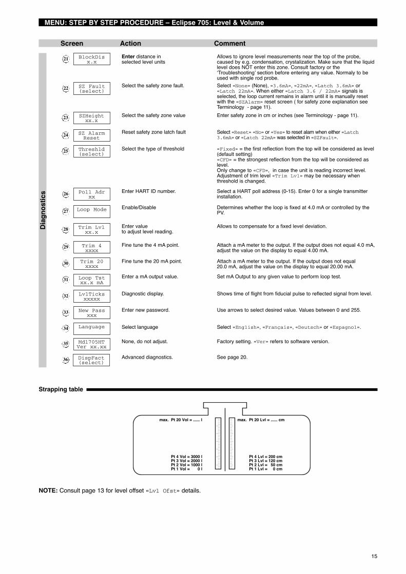
Strapping table
max. Pt 20 Lvl = ...... cm
Pt 4 Lvl = 200 cmPt 3 Lvl = 120 cmPt 2 Lvl = 50 cmPt 1 Lvl = 0 cm
max. Pt 20 Vol = ...... l
Pt 4 Vol = 3000 lPt 3 Vol = 2000 lPt 2 Vol = 1000 lPt 1 Vol = 0 l
36 DispFact(select)
NOTE: Consult page 13 for level offset «Lvl Ofst» details.

16
= Quick Start up
MENU: STEP BY STEP PROCEDURE – Eclipse 705: Interface
Screen Action CommentRu
nm
ode
Confi
gura
tion
1
2
3
4
8
11
12
15
18
19
*Status**IfcLevel**%Output**Loop*
IfcLevelxx.x
%Outputxx.x%
Loopxx.xx mA
5 Levelxxx
MeasType(select)
7 PrbMount(select)
6 PrbModel(select)
10 Probe Lnxxx.x
9 LvlUnits(select)
Lvl Ofstxxx.x
13 Dielctrc(Select)
14 Senstvtyxxx
Upr Diel(Select)
Loop Ctrl(Select)
16 Set 4mAxxx.x
Dampingxx sec
17 Set 20mAxxx.x
Fault(Select)
Transmitter Display Transmitter default values cycle every 5 seconds. Status «Status»,Interface level «Ifclevel», % Output «% Output», and Loop«Loop».
Transmitter Display Transmitter displays interface level in selected engineering units.
Transmitter Display Transmitter displays % Output measurement derived from 20 mAspan.
Transmitter Display Transmitter displays Loop measurement (mA).
Transmitter Display Transmitter displays interface level in selected level units «LvlUnits».
Select the type of probe Select as per the 3 first digits of the probe partnumber. The partnumberis shown on the nameplate: e.g. 705-510A-A11/7MT-A230-218, select7xT-x from the list.
Select the type of probemounting.
Select NPT «NPT», BSP «BSP» or Flange «Flange». (consult facto-ry when a «7xK» GWR probe is used)
Select the type of measurement Select interface «Interface».
Select units for level cm «cm», m «m», inches «inches» or feet «feet».
Enter the exact length ofprobe.
Enter as per the 3 last digits of the probe partnumber on the nameplate:- rigid probes, enter value cm or inches,- flexible probes, enter value in meters or feete.g. 705-510A-A11/7MR-A230-218, enter «218» cm probe length.
Enter the offset value. When entering configuration values from the end of the probe iscumbersome, an offset can be introduced to determine a newreference point. This reference point can be either below theprobe (positive offset) or at the probe (negative offset). See page11 “Terminology”.
Enter the dielectric rangevalue of the upper media.
Enter the dielectrics of the upper layer liquid (between 1,4 and 5,0) –only upper layer dielectrics need to be entered.
Select the dielectric rangevalue of the lower media
Select: «10–100»
Enter sensitivity value Allows fine adjustment of internal gain.
Select primary variable (PV) Primary variable is the loop controlling parameter. Select inter-face level «Ifc Level» or top level «Lvl Only»
Enter the level valuefor the 4 mA point.
A transition zone may exist at the bottom of the probe. See FunctionalSpecifications Probe, see pages 33 up to 37.
Enter the level valuefor the 20 mA point.
A transition zone / blocking distance may exist at the top of the probe.See Functional Specifications Probe, see pages 33 up to 37.
Enter the damping factor. A damping factor (1-10 seconds) may be added to smooth a noisydisplay and/or output due to turbulence.
Enter the value for error. Select «3.6 mA», «22 mA» or hold last value «HOLD». In case ofloop failure, error signal will follow the failing trend; meaning the unitwill show 3.6 mA when the reviewed loop current by the device isfound too low. The unit will show 22 mA in case the reviewed loopcurrent is found too high.

17
MENU: STEP BY STEP PROCEDURE – Eclipse 705: Interface
Screen Action CommentDi
agno
stic
s
26
25
30
31
32
35
Poll Adrxx
IfcThrs(select)
24 Threshld
Trim 20xxxx
Loop Tstxx.x mA
28
29
Trim Lvlxx.x
27 Loop Mode
Trim 4xxxx
LvlTicksxxxxx
New Passxxx
36
37
Language
Mdl705HTVer xx.xx
33
34
IfcTicksxxxx
Medium
20
21
22
23
BlockDisx.x
SZ Fault(select)
SZHeightxx.x
SZ AlarmReset
Enter distance inselected level units
Allows to ignore level measurements near the top of the probe,caused by e.g. condensation, crystalization. Make sure that the liquidlevel does NOT enter this zone. Consult factory or the‘Troubleshooting’ section before entering any value. Normaly to beused with single rod probe.
Select the safety zone fault. Select «None» (None), «3.6mA», «22mA», «Latch 3.6mA» or«Latch 22mA». When either «Latch 3.6 / 22mA» signals isselected, the loop current remains in alarm until it is manually resetwith the «SZAlarm» reset screen ( for safety zone explanation seeTerminology - page 11).
Select the safety zone value Enter safety zone in cm or inches (see Terminology - page 11).
Reset safety zone latch fault Clear a latched safety zone alarm «SZFault».
Select top level threshold. Default selection for most common applications is «Fixed».
Select interface threshold. Default selection for all applications is «CFD». In case the unit doesnot track the correct interface layer, select «Fixed».
Enter HART ID number. Select a HART poll address (0-15). Enter 0 for a single transmitterinstallation.
Enable/Disable Determines whether the loop is fixed at 4.0 mA or controlled by thePV.
Enter valueto adjust level reading.
Allows to compensate for a fixed level deviation.
Fine tune the 4 mA point. Attach a mA meter to the output. If the output does not equal 4.0 mA,adjust the value on the display to equal 4.00 mA.
Fine tune the 20 mA point. Attach a mA meter to the output. If the output does not equal20.0 mA, adjust the value on the display to equal 20.00 mA.
Enter a mA output value. Set mA Output to any given value to perform loop test .
Diagnostic display. Shows time of flight from fiducial pulse to reflected signal from level.
Diagnostic display. Shows time of flight through the upper liquid layer.
Diagnostic display. Shows type of detected upper liquid; unknown «Unknown» oil only«Oil Only», thin oil layer «Thin Oil», thick oil layer «ThickOil», or no level «Dry Probe».
Enter new password. Use arrows to select desired value. Values between 0 and 255.
Select language Select «English», «Français», «Deutsch» or «Espagnol».
None, do not adjust. Factory setting. «Ver» refers to software version.
Advanced diagnostics. See page 20.38 DispFact(select)
No offset(Offset at 0 cm)
Positive offset(Offset at 10 cm)
Negative offset(Offset at -15 cm)
75 cm
100 %
0 %15 cm10 cm
20 mA = 75 cm
4 mA = 15 cm
20 mA = 85 cm
4 mA = 25 cm
20 mA = 60 cm
4 mA = 0 cm
OFFSET

18
= Quick Start up
MENU: STEP BY STEP PROCEDURE – Eclipse 705: Interface & Volume
Screen Action CommentRu
nm
ode
Confi
gura
tion
1
2
3
4
7
13
16
19
22
23
*Status**IfcVol**%Output**Loop*
IfcLevelor Ifc Vol
%Outputxx.x%
Loopxx.xx mA
6 Volumexx.x
Levelxxxx
5 IfcLvlxxxx
12 Probe Lnxxx.x
11 LvlUnits(select)
Lvl Ofstxxx.x
17 Dielctrc(Select)
Upr Diel(Select)
Loop Ctrl(Select)
14 VolUnits
Dampingxx s
15 StrapTblxx pnts
Fault(Select)
Transmitter Display Transmitter default values cycle every 5 seconds. Status «Status»,Interface volume «IfcVolume», % Output «% Output», and Loop«Loop».
Transmitter Display Transmitter displays Interface volume or Interface level in selectedengineering units (depending selection in Loop control «Loop Ctrl»
Transmitter Display Transmitter displays % Output measurement derived from 20 mAspan.
Transmitter Display Transmitter displays Loop measurement (mA).
Transmitter Display Transmitter displays interface level in selected level units«LvlUnits».
Transmitter Display Transmitter displays volume in selected volume units «VollUnits».
Transmitter Display Transmitter displays level in selected level units «LvlUnits».
Select the type of probe Select as per the 3 first digits of the probe partnumber. The partnumberis shown on the nameplate: e.g. 705-510A-A11/7MT-A230-218, select7xT-x from the list.
Select the type of probemounting.
Select NPT «NPT», BSP «BSP» or Flange «Flange». (consult facto-ry when a «7xK» GWR probe is used)
Select the type of measurement Select interface - volume «IfcVol».
Select units for level cm «cm», m «m», inches «inches» or feet «feet».
Enter the exact length ofprobe.
Enter as per the 3 last digits of the probe partnumber on the nameplate:- rigid probes, enter value cm or inches,- flexible probes, enter value in meters or feete.g. 705-510A-A11/7MR-A230-218, enter «218» cm probe length.
Enter the offset value. When entering configuration values from the end of the probe iscumbersome, an offset can be introduced to determine a newreference point. This reference point can be either below theprobe (positive offset) or at the probe (negative offset). See page11 “Terminology”.
Select units for volume. Liters «l» or gallons «g».
Enter level/volumepairs in max 20 steps
Liters «l» or gallons «g».
Enter the dielectric rangevalue of the upper media.
Enter the dielectrics of the upper layer liquid (between 1,4 and 5,0) –only upper layer dielectrics need to be entered.
Select the dielectric rangevalue of the lower media
Select: «10–100»
Enter sensitivity value Allows fine adjustment of internal gain.
Select primary variable (PV) Primary variable is the loop controlling parameter. Select inter-face level «IfcLevel» or interface volume «Ifc Vol»
Enter the level valuefor the 4 mA point.
A transition zone may exist at the bottom of the probe. See FunctionalSpecifications Probe, see pages 33 up to 37.
Enter the level valuefor the 20 mA point.
A transition zone / blocking distance may exist at the top of the probe.See Functional Specifications Probe, see pages 33 up to 37.
Enter the damping factor. A damping factor (1-10 seconds) may be added to smooth a noisydisplay and/or output due to turbulence.
Enter the value for error. Select «3.6 mA», «22 mA» or hold last value «HOLD». In case ofloop failure, error signal will follow the failing trend; meaning the unitwill show 3.6 mA when the reviewed loop current by the device isfound too low. The unit will show 22 mA in case the reviewed loopcurrent is found too high.
10
8 PrbModel(select)
MeasType(select)
9 PrbMount(select)
18 Senstvtyxxx
20 Set 4mAxxx.x
21 Set 20mAxxx.x

19
MENU: STEP BY STEP PROCEDURE – Eclipse 705: Interface & Volume
Screen Action CommentDi
agno
stic
s
31
29
34
35
36
39
Loop Mode
30 Poll Adrxx
IfcThrsh(select)
28 Threshld
Trim 20xxxx
Loop Tstxx.x mA
LvlTicksxxxxx
New Passxxx
40
41
Language
Mdl705HTVer xx.xx
37
38
IfcTicksxxxx
Medium
24
25
26
27
BlockDisx.x
SZ Fault(select)
SZHeightxx.x
SZ AlarmReset
Enter distance inselected level units
Allows to ignore level measurements near the top of the probe,caused by e.g. condensation, crystalization. Make sure that the liquidlevel does NOT enter this zone. Consult factory or the‘Troubleshooting’ section before entering any value. Normaly to beused with single rod probe.
Select the safety zone fault. Select «None» (None), «3.6mA», «22mA», «Latch 3.6mA» or«Latch 22mA». When either «Latch 3.6 / 22mA» signals isselected, the loop current remains in alarm until it is manually resetwith the «SZAlarm» reset screen ( for safety zone explanation seeTerminology - page 11).
Select the safety zone value Enter safety zone in cm or inches (see Terminology - page 11).
Reset safety zone latch fault Clear a latched safety zone alarm «SZFault».
Select top level threshold. Default selection for most common applications is «Fixed».
Select interface threshold. Default selection for all applications is «CFD». In case the unit doesnot track the correct interface layer, select «Fixed».
Enter HART ID number. Select a HART poll address (0-15). Enter 0 for a single transmitterinstallation.
Enable/Disable Determines whether the loop is fixed at 4.0 mA or controlled by thePV.
Enter valueto adjust level reading.
Allows to compensate for a fixed level deviation.
Fine tune the 4 mA point. Attach a mA meter to the output. If the output does not equal 4.0 mA,adjust the value on the display to equal 4.00 mA.
Fine tune the 20 mA point. Attach a mA meter to the output. If the output does not equal20.0 mA, adjust the value on the display to equal 20.00 mA.
Enter a mA output value. Set mA Output to any given value to perform loop test .
Diagnostic display. Shows time of flight from fiducial pulse to reflected signal from level.
Diagnostic display. Shows time of flight through the upper liquid layer.
Diagnostic display. Shows type of detected upper liquid; unknown «Unknown» oil only«Oil Only», thin oil layer «Thin Oil», thick oil layer «ThickOil» or no level «Dry Probe».
Enter new password. Use arrows to select desired value. Values between 0 and 255.
Select language Select «English», «Français», «Deutsch» or «Espagnol».
None, do not adjust. Factory setting. «Ver» refers to software version.
Advanced diagnostics. See page 20.
Strapping table
max. Pt 20 Lvl = ...... cm
Pt 4 Lvl = 200 cmPt 3 Lvl = 120 cmPt 2 Lvl = 50 cmPt 1 Lvl = 0 cm
max. Pt 20 Vol = ...... l
Pt 4 Vol = 3000 lPt 3 Vol = 2000 lPt 2 Vol = 1000 lPt 1 Vol = 0 l
32
33
Trim Lvlxx.x
Trim 4xxxx
42 DispFact(select)
NOTE: Consult page 17 for level offset «Lvl Ofst» details.

20
MENU: STEP BY STEP PROCEDURE: ADVANCED CONFIGURATION
Screen Action Comment
Diag
nost
ics
1
3
4
6
7
8
DispFactSelect
Run timexx h
2 History(current status)
HistoryReset
FidTicksxxxx
5 HF cable(select)
14 Ifc Amplxxx
FidSprdX
Fid Type(select)
9
10
20
Fid Gainxxx
Windowxxx
11 Conv Fctxxxx
12 Scl Ofstxxx
13 Neg Amplxxx
15 Pos Amplxxx
16 Signalxxx
17 Compensate(select)
18 DrateFctXxxx
19 Targ AmplXxxx
Targ TksXxxx
21 Targ CalXxxx
22 OperMode(select)
25
23 7xKCorrxxx
24 ElecTempxxx C
Max Tempxxx C
26 Min Tempxxx C
27 SZ Hystxx.x
Review factory parameters Select «YES» to reveal Factory parameters; «NO» to hide.
Review Diagnostic messages. A cumulative review of all diagnostic messages. Press the enter but-ton twice to clear.
Display mode. Shows time in hours that unit is in operation since last power on.
Diagnostic display. Select «YES» to clear «History».
Superuser parameter Select from 1 m (3') or 3,6 m (12') remote.
Diagnostic display. Shows time of flight from electronics to fiducial pulse. Value shouldremain stable within ± 10 ticks.
Diagnostic display. Value represents the variation of fiducial ticks – a value indicates thatunit is OK, a problematic spread results into an error message.
Select fiducial pulse type.Requires superuser password.
«positive» or «negative» (selection only allowed for someprobes). Consult factory before changing status.
Change gain. Value represents the # of gain applied to the fiducial signal.
None, do not adjust. Factory setting.
None, do not adjust. Factory setting.
None, do not adjust. Factory setting.
Enter new value.Requires superuser password.
Negative amplitude threshold.
Enter new value.Requires superuser password.
Interface amplitude threshold.
Enter new value.Requires superuser password.
Positive amplitude threshold.
Diagnostic display. Indication of signal strength.
Access compensation screens.Requires superuser password.
«None» default.The selection of «Manual» or «Auto» activates the screens 16through 20 for 7MS probes.
None, do not adjust. Diagnostic display if «Compsate» is on «Auto».Shows velocity derating factor.
None, do not adjust. Diagnostic display if «Compsate» is on «Auto».Shows amplitude of steam reference target.
Diagnostic display if «Compsate» is on «Auto».Shows # of ticks from fiducial to steam reference target.
None, do not adjust. Diagnostic display if «Compsate» is on «Auto».Shows the calibrated # of ticks at ambient temperature.
Select operating mode. Selection screen if «Compsate» is on «Auto».Select run automatically «Run», calibrate «Cal», deactivate «Off».
Enter a value.Requires additional password.
Distance in mm (regardless .«LvlUnits») from fiducial to user refer-ence point. Only for 7EK (top/bottom) probe.
None, do not adjust. Shows internal housing temperature.
None, do not adjust. Diagnostic display, shows maximum internal housing temperaturerecorded.
None, do not adjust. Diagnostic display, shows minimum internal housing temperaturerecorded.
None, do not adjust. Safety zone Hysterisis, diagnostic factory setting
Hidden diagnostic screens. Do not acces without assistance or having followed advanced training.

21
For more details about the use of PACTware™ and FDT technology, refer to instruction manual 59-601
PACTware™ – Configuration and Troubleshooting
WHAT IS FDT, PACTware AND DTM
Power
Transmitter
HART connections
24 V DC
PC withHART SerialInterface
• FDT (Field Device Tool) is a new interface code thatdescribes the standardization between frame programs(e.g., PACTware) and DTMs (Device Type Manager).
• PACTware (Process Automation Configuration Tool)is a frame program. It is a device-independent softwareprogram that communicates with all approved DTMs.
• DTM (Device Type Manager) is a device-specific soft-ware driver designed to operate within a FDT compatibleframe program such as PACTware. It includes all specialinformation needed to communicate with a specificdevice (e.g., Pulsar RX5). There are two basic categoriesof DTM’s—Communication (HART, Fieldbus®, Profibus®,etc.) and Field Device (e.g. Pulsar RX5 Radar transmit-ter).
QUICK START
CONNECTIONS
1. Start a projectOpen Pactware and add the Hart modem key and thenthe Magnetrol instrument to your project.Select: «Device» – «add device» – select device(repeat for each device in your project)Important: Make sure that the COM port settings foryour Hart modem key are correct;
2. Connect the devicesSelect in the left window the Magnetrol instrument.Select: «Device» – «connect» (both modem andMagnetrol instrument are getting connected)
3. Configure the instrumentSelect: «Device» – «parameter» – «Online parame-terization»Open «+ Main Menu» and select «+ Device set up»– «Calibration»Parameters can be changed in the window at right, viathe drop down boxes. ENTER confirms the changeonline.
4. Troubleshoot / Monitior the instrumentProcess trend:Select: «Device» – «Additional functions» –«Process Trend»Process trend: all key data (level % Output, Loop, Signalstrength) can be trended and saved, time scales can beadapted.Echo Curve:Select: «Device» – «Additional functions» – «EchoCurve»Echo Curve: shows the actual waveform. The echocurve is an efficient tool for advanced calibration andtroubleshooting.Present Status:Open Main Menu and select «+ Device set up» –«Diagnostics» – «Present status»Present status: shows the entire overview of alldetectable faults and warnings. Blank boxes indicate thehealthy condition of the instrument. Ticked off boxesindicate for a possible fault or warning.
The following diagram shows a typical hardware configura-tion. Observe all safety codes when attaching to instrumentloops in hazardous areas or when measuring flammablemedia. Computers are not intrinsically safe devices.
PACTware™ CD withDTM drivers
Magnetrol recom-mends the VIATOR®
USB HART® Interfacefrom MACTek®
Corporation.

22
PACTware™ – Configuration and Troubleshooting
Echo Curve patterns
Normal oil/water interface
Below screens are examples of the most typical echo curves that occur in normal operation / error condition.
Normal signal pulses from oil over water
Level with Blocking Distance correction
Signal pulse from level. Unit suffered from build up on topof the probe. The introduced blocking distance (see area inframe) solves the problem.
Dry Probe
Signal pulse from an empty vessel/ cage – displayed mes-sage on the unit is «DryProbe» Dry Probe
EOP High or Low
Signal pulse from an empty vessel or cage but with wrong-ly entered probe length – displayed message is «EOPHigh» or «EOP Low» (as shown in graph). Correct theprobe length in either case.
Weak Signal
Signal pulse of a weak signal. Displayed message is«WeakSgnl». Solve this by either to:- change dielectric setting to a lower range or- increase the sensitivity
Threshold Fixed or CFD
Signal pulse of oil over water level. Always select«Threshld Fixed» (as shown in the graph). «ThreshldCFD»will track the stronger reflection pulse. In case of levelmeasurement, the unit will not compensate for the signalvelocity in the upper oil layer and show an erroneous levelreading.

23
CONFIGURATION USING HART®
IMPORTANT: The digital HART® communication is superimposed on the4-20 mA loop and requires a min. load resistance of 250 Ω and a max loadresistance of 450 Ω.
+
+
-
-
Junction
ControlRoom
Display
PowerSupply
CurrentMeter
250 Ω < RL < 450 Ω
CONNECTIONS
CHECK HART®
Connection of your Hart communicator:• at power terminals (+) and (-) in wiring compartment• at first junction box between unit and control room.
Before starting the HART® configuration procedure – check if your HART® commu-nicator is equipped with the proper Eclipse Device Descriptors (DD’s).
I/O start up the communicatorSelect NO: go offlineSelect 4: utilitySelect 5: simulationCheck manufacturer: Magnetrol
HART MENUI/O Start up the device1 Enter Device Set Up «DEVICE SET UP»
Press one of the following alphanumeric keys (if no key is sensed after 5 s, theunit will automatically jump to RUN mode and alternatively show Level/% Outputand Loop signal1 for entering Calibration «CALIBRATION» (see page 24 for additional informa-
tion)2 for entering Basic Set Up «BASIC SET UP» – general HART3 for Advanced Set Up «ADVANCED SET UP» (see page 24 for additional infor-
mation)4 for entering Diagnostics «DIAGNOSTICS» (see page 24 for additional infor-
mation)5 for entering Review «REVIEW» to review all settings.
When the proper software version is not found, consult your local HART® ServiceCenter to load the correct Eclipse DD’s.
HCF Release Date HART Version Model Compatible with softwareJune 2005 Dev V1 DD V1 705 3.x Version 3.0 and laterSeptember 2008 Dev V1 DD V2 Version 3.0A and laterAugust 2011 Dev V2 DD V1 Version 3.2A and later

24
CONFIGURATION USING HART®
1 Calibration 2 Basic Setup 3 Advanced Setup 4 Diagnostics 5 Review
1 Device Setup 2 Level 3 % Range 4 Loop 5 Device Variables
1 Tag2 Descriptor3 Date4 Message5 Poll Address6 Final Asmbly Num
1 Model2 Manufacturer3 Magnetrol S/N4 Firmware Version5 Tag6 Descriptor7 Date8 Message9 Poll Address
10 Final asmbly num 11 Device ID 12 Probe Model13 Probe Mount14 Measurement Type
16 Probe Length15 Level Units
17 Level Offset18 Volume Units19 Dielectric Range20 Sensitivity21 PV is22 SV is23 TV is24 QV is25 4mA Set Point26 20mA Set Point27 Damping28 System Fault State29 Blocking Distance30 SZ Fault State31 SZ Height32 Trim Level33 4 mA Trim Value34 20 mA Trim Value35 Threshold36 Interface Threshold37 Fiducial Type38 Fiducial Gain39 Neg Threshold Ampl40 Pos Threshold Ampl41 Ifc Threshold Ampl42 Compensation Mode43 Upper Dielectric44 7xK Correction45 SZ Hysteresis46 Universal rev47 Field dev rev48 Software rev49 Num req preams
3 Measurement Type4 Level Units
6 Level Offset7 Volume Parameters
9 Sensitivity8 Dielectric Range
10 PV is11 Variable Selection12 4 mA Set Point13 20 mA Set Point14 Damping15 System Fault State16 Blocking Distance17 SZ Fault State18 SZ Height19 SZ Alarm Reset20 Threshold21 Interace Params22 Trim Level23 Date/Time/Initials
5 Probe Length
1 Probe Model2 Probe Mount
1 Faults2 Warnings
1 Loop Test2 Present Status3 Status History4 Level Ticks5 Fiducial Ticks6 Fiducial Spread7 Signal Strength8 Elec Temperature9 Interface Ticks
10 Interface Medium11 Derating Factor12 Target Amplitude13 Target Ticks
1 Software Failure2 CPU Failure3 EEPROM Failure4 Default Params5 No End of Ramp6 Loop Failure7 Fiducial Shift8 Slope Error9 No Probe
10 No Fiducial11 Safety Zone Alrm12 No Signal13 EOP High14 Hi Volume Alrm15 Lvl < Probe Length16 EOP < Probe Length
1 Trim Loop Current2 Enter Password
3 Fiducial Type4 Fiducial Gain5 Neg Threshold Ampl6 Pos Threshold Ampl7 Compensation8 Factory Settings9 SZ Hystersis
10 Max Temperature11 Min Temperature12 Reset Temperatures13 New User Password
1 Level2 Volume3 IfcLvl4 IfcVol
3 Table Length2 Strapping Table1 Volume Units
3 QV IS2 TV IS1 SV IS
3 Ifc Threshold Ampl2 Interface Threshold1 Upper Dielectric
1 Magnetrol S/N2 Device ID3 HF Cable4 Window5 Conversion Factor6 Scale Offset7 Waveform Selection8 Factory Param 2
1 Compensation Mode2 Upper Dielectric3 Target Calibration4 7xK Correction
1 Target Oper Mode2 Target Calib Value3 Auto Target Calib
1 Seal Leak2 Fiducial Spread3 Hi Temperature4 Lo Temperature5 Calib Required6 EOP Too Low7 Trim Required8 Initializing9 May Be Flooded
10 Dry Probe11 Weak Signal12 System Warning13 Warning 114 Warning 215 No Steam Target16 Warning 4

25
MAINTENANCE
TROUBLESHOOTING
Symptom Problem Solution
LEVEL, % OUTPUT and LOOP valuesare all inaccurate.
Basic configuration data isquestionable.
Reconfigure the Probe Length «Prb Ln»and Offset «Offset». Check also theProbe Model «Prb Model» / ProbeMount «Prb Mount»
1) Ensure the Level is accurate.2) Reconfigure Loop values.
Interface level has significant emulsion. Examine process to reduce/eliminateemulsion layer.
LEVEL readings are repeatable butconsistently high or low from actualby a fixed amount.
Configuration data does notaccurately match probe length or tankheight.
Ensure proper probe length «Prb Ln» &probe Model «Prb Model».Adjust trim level value by the amount ofnoted inaccuracy.
LEVEL, % OUTPUT and LOOPvalues fluctuate.
Turbulence. Increase the Damping «Damping» factoruntil the readings stabilize.
High frequency connection. Check Fiducial Spread «FidSprd»(should be stable within ± 10 counts.)
LEVEL, % OUTPUT and LOOPvalues all reading low vs. actual(level or volume applications).
Lower dielectric material over higherdielectric material, e.g. oil over water.
Select Fixed Threshold option «Fixed»and/or select dielectric range from top layer.
Coating, clumping or buildup on probe. Expected inaccuracies due to affect onpulse propagation.
Dense, water based foam. Expected inaccuracies due to affect onpulse propagation.
LEVEL reading on Display is correctbut LOOP is stuck on 4 mA
Basic configuration datais questionable.
Set Hart poll address «POLL ADR» to«0». If not using HART® multi drop
HART device only: handheld will onlyread Universal Commands.
Most current Device Descriptors(DDs) are not installed in handheld.(see page 20)
Contact local HART service center forthe latest DD’s.
LEVEL reading on display is stuckat full scale, LOOP is stuck at 20,5 mA.
Software believes probe is flooded(level near very top of probe).
Check actual level. If probe is not flood-ed, check for build up or obstructionsnear top of probe. Select higher dielec-tric range.Check for condensation in probe con-nection. Add Blocking Distance.
LEVEL, % OUTPUT and LOOPvalues all at maximum level.
Possible configuration issue with singlerod probe
1) Increase Blocking Distance2) Increase Dielectric Range
LEVEL, % OUTPUT and LOOPvalues all reading high vs. actual.
Possible obstruction in tank affectingsingle rod probe.
1) Increase Dielectric Range untilobstruction is ignored.
2) Relocate probe away from obstruc-tion.
LEVEL value reading high whenshould be zero.
Transmitter loose or disconnectedfrom probe.
Ensure transmitter connected securelyto probe.
HART ERROR MESSAGES
Error Screen Displayed status
Faults Enlists possible error messages. OFF: safe statusON: highlighted error is occurring – seepage 27
Warnings Enlists warning messages. OFF: safe statusON: highlighted warning is occurring –see page 26
History Built in log of the last 26 error messages. See page 20.
PACTware™ PC ProgramThe Eclipse Model 705 offers the ability to do Trending and Echo Curve analysis using a PACTware DTM. This is a powerful troubleshoot-ing tool that can aid in the resolution of some of the Error Messages shown above.
Refer to Bulletins 59-101 and 59-601 for more information.
26
MAINTENANCE
DisplayMessage Action Comment
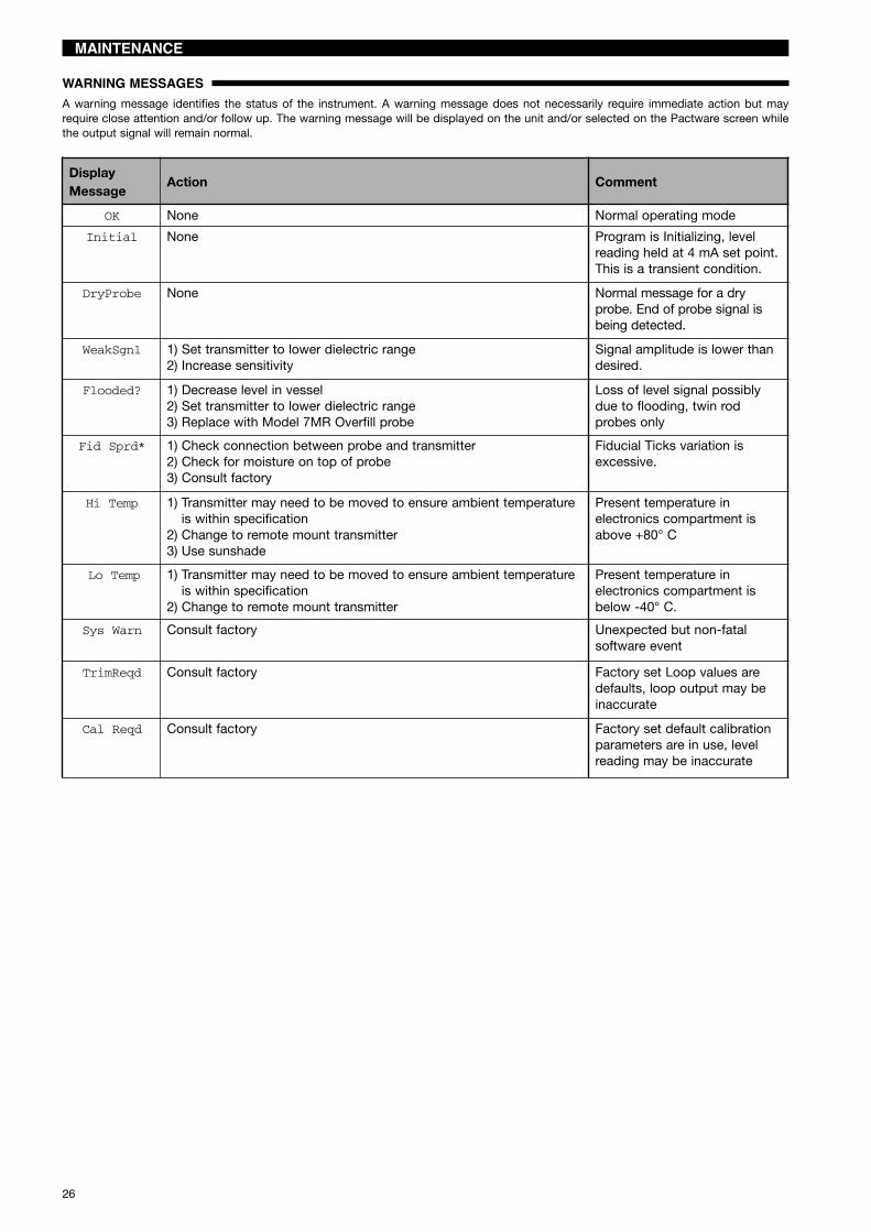
OK None Normal operating mode
Initial None Program is Initializing, levelreading held at 4 mA set point.This is a transient condition.
DryProbe None Normal message for a dryprobe. End of probe signal isbeing detected.
WeakSgnl 1) Set transmitter to lower dielectric range2) Increase sensitivity
Signal amplitude is lower thandesired.
Flooded? 1) Decrease level in vessel2) Set transmitter to lower dielectric range3) Replace with Model 7MR Overfill probe
Loss of level signal possiblydue to flooding, twin rodprobes only
Fid Sprd* 1) Check connection between probe and transmitter2) Check for moisture on top of probe3) Consult factory
Fiducial Ticks variation isexcessive.
Hi Temp 1) Transmitter may need to be moved to ensure ambient temperatureis within specification
2) Change to remote mount transmitter3) Use sunshade
Present temperature inelectronics compartment isabove +80° C
Lo Temp 1) Transmitter may need to be moved to ensure ambient temperatureis within specification
2) Change to remote mount transmitter
Present temperature inelectronics compartment isbelow -40° C.
Sys Warn Consult factory Unexpected but non-fatalsoftware event
TrimReqd Consult factory Factory set Loop values aredefaults, loop output may beinaccurate
Cal Reqd Consult factory Factory set default calibrationparameters are in use, levelreading may be inaccurate
WARNING MESSAGESA warning message identifies the status of the instrument. A warning message does not necessarily require immediate action but mayrequire close attention and/or follow up. The warning message will be displayed on the unit and/or selected on the Pactware screen whilethe output signal will remain normal.
27
MAINTENANCE
DisplayMessage Action Comment
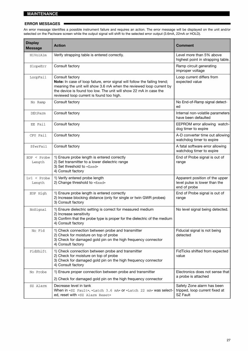
HiVolAlm Verify strapping table is entered correctly. Level more than 5% abovehighest point in strapping table.
SlopeErr Consult factory Ramp circuit generatingimproper voltage
LoopFail Consult factoryNote: In case of loop failure, error signal will follow the failing trend;meaning the unit will show 3.6 mA when the reviewed loop current bythe device is found too low. The unit will show 22 mA in case thereviewed loop current is found too high.
Loop current differs fromexpected value
No Ramp Consult factory No End-of-Ramp signal detect-ed
DfltParm Consult factory Internal non-volatile parametershave been defaulted
EE Fail Consult factory EEPROM error allowing watch-dog timer to expire
CPU Fail Consult factory A-D converter time out allowingwatchdog timer to expire
SfwrFail Consult factory A fatal software error allowingwatchdog timer to expire
EOP < ProbeLength
1) Ensure probe length is entered correctly2) Set transmitter to a lower dielectric range3) Set threshold to «fixed»4) Consult factory
End of Probe signal is out ofrange
Lvl < ProbeLength
1) Verify entered probe length2) Change threshold to «fixed»
Apparent position of the upperlevel pulse is lower than theend of probe
EOP High 1) Ensure probe length is entered correctly2) Increase blocking distance (only for single or twin GWR probes)3) Consult factory
End of Probe signal is out ofrange
NoSignal 1) Ensure dielectric setting is correct for measured medium2) Increase sensitivity3) Confirm that the probe type is proper for the dielectric of the medium4) Consult factory
No level signal being detected.
No Fid 1) Check connection between probe and transmitter2) Check for moisture on top of probe3) Check for damaged gold pin on the high frequency connector4) Consult factory
Fiducial signal is not beingdetected
FidShift 1) Check connection between probe and transmitter2) Check for moisture on top of probe3) Check for damaged gold pin on the high frequency connector4) Consult factory
FidTicks shifted from expectedvalue
No Probe 1) Ensure proper connection between probe and transmitter
2) Check for damaged gold pin on the high frequency connector
Electronics does not sense thata probe is attached
SZ Alarm Decrease level in tankWhen in «SZ Fault», «Latch 3.6 mA» or «Latch 22 mA» was select-ed, reset with «SZ Alarm Reset»
Safety Zone alarm has beentripped, loop current fixed atSZ Fault
ERROR MESSAGESAn error message identifies a possible instrument failure and requires an action. The error message will be displayed on the unit and/orselected on the Pactware screen while the output signal will shift to the selected error output (3.6mA, 22mA or HOLD).

28
MAINTENANCE
TROUBLESHOOTING APPLICATIONS: Level
TROUBLESHOOTING APPLICATIONS: Interface
Most frequent application problems that may occur, mediabuildup on the probe and stratification, are covered here.Media buildup on the probe is not a problem in mostcases–Eclipse circuitry typically works very effectively.Media buildup should be viewed as two types – FilmCoating and Bridging.Recommended guidelines to select the right GWR probe:- Relatively clean liquids: use the standard coax GWR
probes- Possible build up: use the enlarged coax or twin rod
GWR probe- Extreme build up: use the single rod GWR probe
• Continuous Film CoatingThe most typical of coating problems where the mediaforms a continuous coating on the probe. Eclipse willcontinue to measure effectively with some small degra-dation in performance. A problem can develop if theproduct begins to buildup on the spacers that separatethe probe elements. High dielectric media (e.g, water-based) will cause the greatest error.
• BridgingMedia that is viscous or solid enough to form a clog, orbridge, between the elements causes the greatestdegradation in performance. High dielectric media (eg.water-based) will show as level at the location of thebridging.
• Stratification/InterfaceThe Eclipse transmitter is designed to measure the firstair/media interface it detects, when configured for levelmeasurement only. It will not measure further liquid/liquid interfaces. However, a low dielectric over a highdielectric application can cause a measurement problemif the level of the low dielectric medium becomes smallenough (a few cm) to cause the electronics to trigger onthe high dielectric medium that lies beneath it. Select theFixed Threshold option to read the upper medium.Example: oil over water.
FilmCoating
Bridging
FilmCoating
Threshold«Fixed»GOOD
Threshold«CFD»
WRONG
Outer tube
Inner rod
Bridging
Oilεr 2.0
EmulsionLayer
Air/gas
<εr
>εr
Waterεr 80
It is not uncommon for interface applications to have anemulsion layer form between the two media. This emulsionlayer may pose problems for Guided Wave Radar as it maydecrease the strength of the reflected signal. Since theproperties of this emulsion layer are difficult to quantify,applications with emulsion layer should be avoided withEclipse.
Continuous film coating / Bridging Stratification/Interface

29
MAINTENANCE
TROUBLESHOOTING APPLICATIONS: Single Rod type GWR probe
Most frequent application problems that may occur, mediabuildup on the probe and stratification, are covered here.Significant buildup on the probe is not a problem in mostcases–Eclipse circuitry typically works very effectively.• Nozzles (only for 7MF/7M1/7M2/7MJ)
Nozzles can create false echoes that can cause diag-nostic messages and/or errors in measurement. If endof probe high «Eop High» is displayed when first con-figuring the instrument:1. Ensure the probe length «Prb Ln» as entered in the
software is equal to the actual probe length (see page12, item 9). This value must be changed if the probeis cut shorter from the original length.
2. Increase the blocking distance «BlockDis» valueuntil the message is eliminated; 20 mA point mayneed to be lowered.
3. Increase the dielectric range a small amount ordecrease the sensitivity to aid in reducing echoes innozzle. Increasing the dielectric settings may causeinstrument to lose level of lower dielectric media; con-sult factory.
• Obstructions (only for 7MF/7M1/7M2/7MJ)If the level reading repeatedly locks on to a specific levelhigher than the current level, it may be caused by ametallic obstruction. Obstructions in the vessel (e.g.pipes, ladders) that are located close to the probe maycause the instrument to show them as level.1. Refer to the Probe Clearance Table2. Increase the dielectric range a small amount or
decrease the sensitivity to aid in reducing disturbingechoes in nozzle. Increasing the dielectric settingsmay cause instrument to lose level of lower dielectricmedia; consult factory.
• Coating/build-up (only for 7MF/7M1/7M2/7MJ)The Eclipse® 705 wih Single Rod Probe was designed tooperate effectively in the presence of media building up.Some expected error may be generated based upon thefollowing factors: Dielectric of the media that created the coating Thickness of the coating Length of the coating above the present levelIn case build up is picked up as level, increase thedielectric range a small amount or decrease the sensi-tivity.
• Coating/build-up (only for 7M7/7M5)Continuous film coating is where the media forms a thincontinuous coating on the probe. Eclipse® will continueto measure effectively with some degradation in perfor-mance. The degradation is proportional to the dielectricof the media and the thickness of the coating up to adegree that the unit will see coating as a level. Higherdielectric media (eg. water based) will show sooner as alevel at the location of the build up.
Obstruction
Nozzles• 2" diameter minimum• Ratio of diameter: length should be > 1:1
If not, set blocking distance at 2 x nozzle height• Do not use pipe reducers (restriction)
Coating Build-up
Distance to probe Acceptable objects< 150 mm (6") Continuous, smooth, parallel,
conductive surface (e.g. metaltank wall); probe should not touchtank wall
> 150 mm (6") < 1"/DN25 diameter pipe andbeams, ladder rungs
> 300 mm (12") < 3"/DN80 diameter pipe andbeams, concrete walls
> 450 mm (18") All remaining objects
Probe clearance table

30
REPLACEMENT PARTS
1
2
3
4
3
5
5
3
CAUTION: the electronic module connects to the antenna via the “High frequency connector”. This part isextremely sensitive and brittle and requires to be handled very careful. It is recommended to exchange completeamplifier heads instead of electronic modules in the field.
1X 742 3 8 9 105 6Digit in partn°:
7 50 5Partn°:
= Industrial Eclipse 705= Hygienic Eclipse 705
X = product with a specific customer requirement
Electronic Module (1)Digits Replacement part
5 6 & 7 9 Hart
1
001, 2,7 or
8
Z31-2835-0020A Z31-2835-001A0 Z31-2835-004AA Z31-2835-003
00 or 0A 3 or9
089-7254-001A0 or AA 089-7254-003
FF
200 1, 2,
7 or 8Z31-2841-002
0A Z31-2841-00100 or 0A 3 or 9 089-7254-002
Profibus PA
300 1, 2,
7 or 8Z31-2846-002
0A Z31-2846-00100 or 0A 3 or 9 089-7254-004
Wiring board (2)Digits Replacement part
5 8 9 Hart1 all
1, 2,7 or 8
Z30-9151-001FF - Profibus PA
2or3
1, 2, A or B Z30-9151-0043, 4, C, D, E,
or F Z30-9151-003
Housing cover (5)Digits Replacement part7 8 9
0 all 1 or 7 004-9193-003all 2 or 8 004-9193-007
A
1, 2, A, B, Eor F 1 or
7036-4410-001
3, 4, C or D 036-4410-003all 2 or 8 036-4410-004
0 all 3 or9
036-5702-003A 036-5702-002
Housing “O” ring (3)Digit 9 Replacement part
1, 2, 7 or 8 012-2201-2373 or 9 012-2201-155
Housing cover (4)Digit 9 Replacement part1 or 7 004-9193-0032 or 8 004-9193-007
Industrial
Hygienic
Serial n°:See nameplate, always provide complete partn° andserial n° when ordering spares.
31
REPLACEMENT PARTS
11
8 9
8 9
8 9
76
10
10
12
9
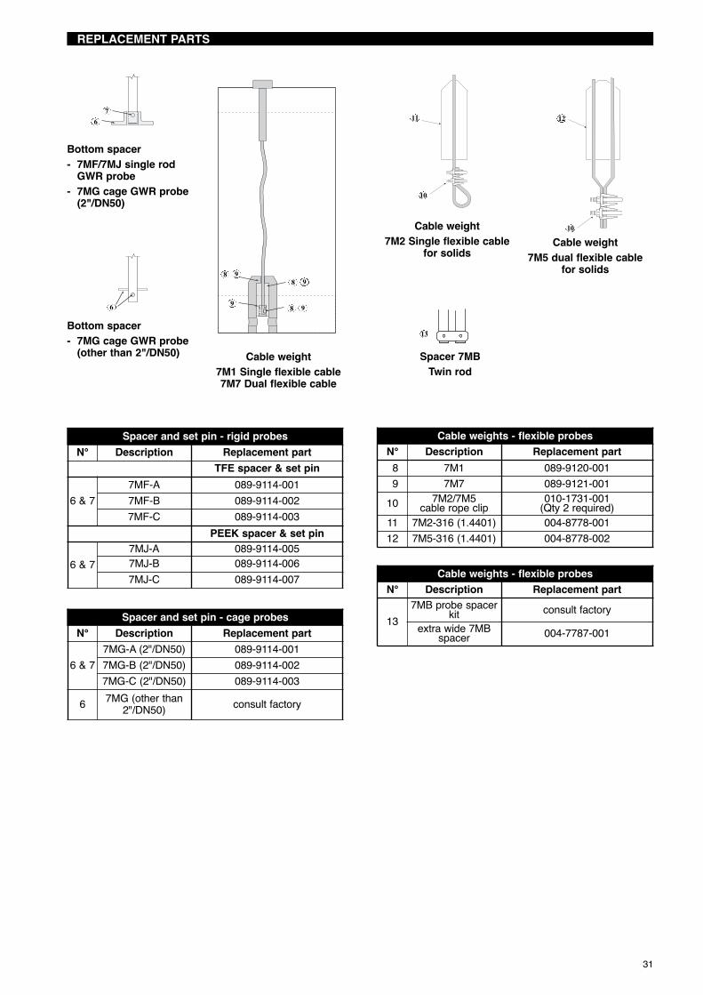
Cable weight7M1 Single flexible cable7M7 Dual flexible cable
Bottom spacer- 7MF/7MJ single rod
GWR probe- 7MG cage GWR probe
(2"/DN50)
Cable weight7M2 Single flexible cable
for solids
Spacer 7MBTwin rod
Cable weight7M5 dual flexible cable
for solids
6
Bottom spacer- 7MG cage GWR probe
(other than 2"/DN50)13
Spacer and set pin - rigid probesN° Description Replacement part
TFE spacer & set pin
6 & 77MF-A 089-9114-0017MF-B 089-9114-0027MF-C 089-9114-003
PEEK spacer & set pin
6 & 77MJ-A 089-9114-0057MJ-B 089-9114-0067MJ-C 089-9114-007
Spacer and set pin - cage probesN° Description Replacement part
6 & 77MG-A (2"/DN50) 089-9114-0017MG-B (2"/DN50) 089-9114-0027MG-C (2"/DN50) 089-9114-003
6 7MG (other than2"/DN50) consult factory
Cable weights - flexible probesN° Description Replacement part8 7M1 089-9120-0019 7M7 089-9121-001
10 7M2/7M5cable rope clip
010-1731-001(Qty 2 required)
11 7M2-316 (1.4401) 004-8778-00112 7M5-316 (1.4401) 004-8778-002
Cable weights - flexible probesN° Description Replacement part
137MB probe spacer
kit consult factoryextra wide 7MB
spacer 004-7787-001

32
TRANSMITTER SPECIFICATIONS
PERFORMANCEDescription SpecificationReference Conditions with a 1,8 m (72")coaxial type GWR probe
Reflection from liquid, with dielectric in center of selected range, at +20 °C (70 °F) withCFD threshold
Linearity Coaxial/twin lead probes < 0,1 % of probe length or 2,5 mm (0.1"), whichever is greaterSingle lead probes < 0,3 % of probe length or 8 mm (0.3"), whichever is greater
Accuracy Coaxial/twin lead probes < 0,1 % of probe length or 2,5 mm (0.1"), whichever is greaterSingle lead probes ± 0,5 % of probe length or 13 mm (0.5"), whichever is greater7MT/7ML interface ± 25 mm (1")
Resolution ± 2,5 mm (0.1")Repeatability < 2,5 mm (0.1")Hysteresis < 2,5 mm (0.1")Response Time < 1 secondWarm-up Time < 5 secondsAmbient Temp. -40 °C to +80 °C (-40 °F to +175 °F) – blind transmitter
-20 °C to +70 °C (-5 °F to +160 °F) – with digital display-40 °C to +70 °C (-40 °F to +160 °F) – for EEx ia and EEx d[ia] with blind transmitter-20 °C to +70 °C (-5 °F to +160 °F) – for EEx ia and EEx d[ia] with digital display
Process Dielectric Effect < 7,5 mm (0.3") within selected rangeOperating Temp. Effect Approx. +0,02 % of probe length/°C for probes ≥ 2,5 m (8')Humidity 0-99 %, non-condensingElectromagnetic Compatibility Meets CE requirements (EN-61326: 1997 + A1 + A2) and NAMUR NE 21
(Single and Twin-Rod probe must be used in metallic vessel or stillwell)
FUNCTIONAL/PHYSICAL
Foundation Fieldbus™ and Profibus PA™ units. For ATEX flameproof enclosure units use Ex d bushing material
STYCAST 2057 FR. May degrade for 7MD/7ML probe or with fixed threshold.
Top 600 mm (24") of twin rod probe: 30 mm (1.18").Top 1220 mm (48") of single rod: application dependant.
Accuracy may degrade slightly < 2,5 m (8')
Description SpecificationPower (at terminals) HART®:
- Weatherproof / ATEX flameproof enclosure / ATEX non sparking: 11 to 36 V DC- ATEX Intrinsically Safe: 11 to 28,4 V DC
Output 4-20 mA with HART®, 3,8 mA to 20,5 mA useable (meets NAMUR NE 43)Span 15 cm to 22 m (6" to 72.18') depending on selected probeResolution Analog: 0,01 mA
Display: 0,1 (cm or inch)Loop Resistance 630 Ω @ 20,5 mA - 24 V DCDamping Adjustable 0-10 sDiagnostic Alarm Adjustable 3,6 mA, 22 mA, HOLD last outputUser Interface HART® communicator, AMS® or PACTware™ and/or 3-button keypadDisplay 2-line x 8-character LCDMenu Language English/Spanish/French/GermanHousing Material IP 66/Aluminium A356T6 (< 0.20 % copper) or stainless steelApprovals ATEX II 3 (1) G EEx nA [ia] IIC T6, non sparking (probe can be used in flammable liquids)
ATEX II 3 (1) G EEx nA [nL][ia] IIC T6, FNICO – non incendive (probe can be used inflammable liquids)ATEX II 1 G Ex ia IIC T4 Ga, intrinsically safeATEX II 1 G Ex ia IIC T4 Ga, FISCO – intrinsically safe
ATEX II 1/2 G Ex d[ia Ga] IIC T6 Gb
ATEX II 1/2 D Ex t[ia Da] IIIC T85°C Db IP66
IEC Ex d[ia Ga] IIC T6 GbIEC Ex t[ia Da] IIIC T85°C Db IP66IEC Ex ia IIC T4 Ga, intrinsically safeIEC Ex ia IIC T4 Ga, FISCO – intrinsically safe
IEC Ex ic [ia Ga] IIC T4 GcIEC EN 12952-11 and EN 12953-9 CE approved for steam drums as primary level safety deviceTÜV – WHG § 63, VLAREM II 5.17-7LRS – Lloyds Register of Shipping (marine applications)Other approvals are available, consult factory for more details
SIL(Safety Integrity Level)
Standardelectronics
Functional safety to SIL 1 as 1oo1 / SIL 2 as 1oo2 in accordance to IEC 61508 – SFF of85,4 % – full FMEDA reports and declaration sheets available at request
Enhancedelectronics
Functional safety to SIL 2 as 1oo1 in accordance to IEC 61508 – SFF of 91 %– full FMEDA reports and declaration sheets available at request.Certified for use in SIL 3 loops.
Electrical Data Ui = 28,4 V, li = 120 mA, Pi = 0,84 W (HART®)Equivalent Data Ci = 2,2 nF, Li = 3 µH (HART®)Shock/Vibration Class ANSI/ISA-S71.03 Class SA1 (Shock), ANSI/ISA-S71.03 Class VC2 (Vibration)Net weight Cast aluminium 2,7 kg (6.0 lbs) – transmitter head / electronics only
Stainless steel 5,7 kg (12.6 lbs) – transmitter head / electronics onlyOverall Dimensions H 214 mm (8.43") x W 111 mm (4.38") x D 188 mm (7.40")
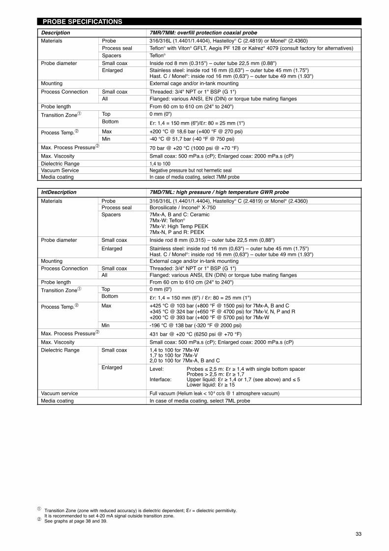
33
PROBE SPECIFICATIONS
Transition Zone (zone with reduced accuracy) is dielectric dependent; εr = dielectric permitivity.It is recommended to set 4-20 mA signal outside transition zone.
See graphs at page 38 and 39.
Description 7MR/7MM: overfill protection coaxial probeMaterials Probe 316/316L (1.4401/1.4404), Hastelloy® C (2.4819) or Monel® (2.4360)
Process seal Teflon® with Viton® GFLT, Aegis PF 128 or Kalrez® 4079 (consult factory for alternatives)Spacers Teflon®
Probe diameter Small coax Inside rod 8 mm (0.315") – outer tube 22,5 mm (0.88")Enlarged Stainless steel: inside rod 16 mm (0,63") – outer tube 45 mm (1.75")
Hast. C / Monel®: inside rod 16 mm (0,63") – outer tube 49 mm (1.93")Mounting External cage and/or in-tank mountingProcess Connection Small coax Threaded: 3/4" NPT or 1" BSP (G 1")
All Flanged: various ANSI, EN (DIN) or torque tube mating flangesProbe length From 60 cm to 610 cm (24" to 240")Transition Zone Top 0 mm (0")
Bottom εr: 1,4 = 150 mm (6")/εr: 80 = 25 mm (1")Process Temp. Max +200 °C @ 18,6 bar (+400 °F @ 270 psi)
Min -40 °C @ 51,7 bar (-40 °F @ 750 psi)Max. Process Pressure 70 bar @ +20 °C (1000 psi @ +70 °F)Max. Viscosity Small coax: 500 mPa.s (cP); Enlarged coax: 2000 mPa.s (cP)Dielectric Range 1,4 to 100Vacuum Service Negative pressure but not hermetic sealMedia coating In case of media coating, select 7MM probe
IntDescription 7MD/7ML: high pressure / high temperature GWR probeMaterials Probe 316/316L (1.4401/1.4404), Hastelloy® C (2.4819) or Monel® (2.4360)
Process seal Borosilicate / Inconel® X-750Spacers 7Mx-A, B and C: Ceramic
7Mx-W: Teflon®
7Mx-V: High Temp PEEK7Mx-N, P and R: PEEK
Probe diameter Small coax Inside rod 8 mm (0.315) – outer tube 22,5 mm (0,88")Enlarged Stainless steel: inside rod 16 mm (0,63") – outer tube 45 mm (1.75")
Hast. C / Monel®: inside rod 16 mm (0,63") – outer tube 49 mm (1.93")Mounting External cage and/or in-tank mountingProcess Connection Small coax Threaded: 3/4" NPT or 1" BSP (G 1")
All Flanged: various ANSI, EN (DIN) or torque tube mating flangesProbe length From 60 cm to 610 cm (24" to 240")Transition Zone Top 0 mm (0")
Bottom εr: 1,4 = 150 mm (6") / εr: 80 = 25 mm (1")Process Temp. Max +425 °C @ 103 bar (+800 °F @ 1500 psi) for 7Mx-A, B and C
+345 °C @ 324 bar (+650 °F @ 4700 psi) for 7Mx-V, N, P and R+200 °C @ 393 bar (+400 °F @ 5700 psi) for 7Mx-W
Min -196 °C @ 138 bar (-320 °F @ 2000 psi)Max. Process Pressure 431 bar @ +20 °C (6250 psi @ +70 °F)Max. Viscosity Small coax: 500 mPa.s (cP); Enlarged coax: 2000 mPa.s (cP)Dielectric Range Small coax 1,4 to 100 for 7Mx-W
1,7 to 100 for 7Mx-V2,0 to 100 for 7Mx-A, B and C
Enlarged Level: Probes ≤ 2,5 m: εr ≥ 1,4 with single bottom spacerProbes > 2,5 m: εr ≥ 1,7
Interface: Upper liquid: εr ≥ 1,4 or 1,7 (see above) and ≤ 5Lower liquid: εr ≥ 15
Vacuum service Full vacuum (Helium leak < 10-8 cc/s @ 1 atmosphere vacuum)Media coating In case of media coating, select 7ML probe

34
PROBE SPECIFICATIONS
Transition Zone (zone with reduced accuracy) is dielectric dependent; εr = dielectric permitivity.It is recommended to set 4-20 mA signal outside transition zone / blocking distance.
See graphs at page 38 and 39.
Description 7MF: standard single rod 7MJ: HTHP single rod
Materials
Probe(industrial)
316/316L (1.4401/1.4404), Hastelloy® C (2.4819),Monel® (2.4360), or PFA insulated 316/316L(1.4401/1.4404)
316/316L (1.4401/1.4404), Hastelloy® C (2.4819)or Monel® (2.4360)
Probe(hygienic)
316/316L (1.4401/1.4404), Hastelloy® C22(2.4602) or AL-6XN stainless steel (UNS N08367) -
Process sealTFE with Viton® GFLT, Aegis PF 128 or Kalrez®
4079 (consult factory for alternatives)Hygienic: PTFE facing
PEEK with Aegis PF 128
Probe diameterBare: 13 mm (0.50") -PFA coated: 16 mm (0.625")Hygienic: 13 mm (0,50") or 6 mm (0,25")
Bare: 13 mm (0.50")
Process ConnectionThreaded: 2" NPT or 2" BSP (G 2")Flanged: various ANSI or EN (DIN) flangesHygienic: Tri-Clamp (7MF only)
Probe length From 60 cm to 610 cm (24" to 240"); hygienic down to 30 cm (12")Blocking distance (top) 120 mm up to 910 mm (4.8" up to 36") - depending probe length (adjustable)Transition Zone (bottom) εr ≥ 10: 25 mm (1")
Process Temp.
Max +150 °C @ 27,6 bar (+300 °F @ 400 psi)Hygienic: +150 °C @ 13,8 bar (+300 °F @ 200 psi) +315 °C @ 155 bar (+600 °F @ 2250 psi)
Min 7MF-F: -40 °C @ 13,8 bar (-40 °F @ 200 psi)Other 7MF-probes: -40 °C @ 51,7 bar (-40 °F @750 psi)Hygienic: -40 °C @ 13,8 bar (-40 °F @ 200 psi)
-15 °C @ 245 bar (0 °F @ 3550 psi)
Max Process Pressure 70 bar @ +20 °C (1000 psi @ +70 °F)Hygienic: 13,8 bar @ +150 °C (200 psi @ +300 °F) 245 bar @ +20 °C (3550 psi @ +70 °F)
Max Viscosity 10.000 mPa.s (cP) – consult factory in case of agitation/turbulenceDielectric Range εr: 10-100 (depending installation conditions, down to εr ≥ 1,9)Vacuum service Negative pressure but not hermetic seal
Media coating Max error of 10 % of coated length. % Error is related to dielectric of medium, thickness of coating andcoated probe length above level.
Description 7MS: saturated steam GWR probeMaterials Probe 316/316L (1.4401/1.4404)
Process seal High Temp PEEK with Aegis PF 128Spacers High Temp PEEK
Probe diameter Inside rod 8 mm (0.315) – outer tube 22,5 mm (0,88")Mounting External cage and/or in-tank mountingProcess Connection Threaded: 3/4" NPT or 1" BSP (G 1")
Flanged: various ANSI, EN (DIN) or torque tube mating flangesProbe length From 60 cm to 450 cm (24" to 177")Transition Zone Top 200 mm (8"); consult factory for overfill applications
Bottom εr ≥ 10 = 25 mm (1")Process Temp. Max +345 °C @ 155 bar (+650 °F @ 2250 psi)
Min -15 °C @ 207 bar (0 °F @ 3000 psi)Max. Process Pressure 155 bar @ +345 °C (2250 psi @ +650 °F)Max. Viscosity 500 mPa.s (cP)Dielectric Range 10 to 100Vacuum service Negative pressure but not hermetic sealMedia coating Not applicable

35
PROBE SPECIFICATIONS
Transition Zone (zone with reduced accuracy) is dielectric dependent; εr = dielectric permitivity.It is recommended to set 4-20 mA signal outside transition zone / blocking distance.
See graphs at page 38 and 39.
Description 7M1 (liquids) / 7M2 (solids): single flexible 7M5 (solids) /7M7 (liquids): twin flexible
MaterialsProbe 316 SST (1.4401) FEP coated 316 SST (1.4401)
Process seal 7M1/7M7: Teflon® with Viton® GFLT, Aegis PF 128 or Kalrez® 4079 (consult factory for alternatives)7M2/7M5: Teflon® with Viton® GFLT
Probe diameter 7M1: 5 mm (0.19")7M2: 6 mm (0.25") 6 mm (0.25")
Process Connection Threaded: 2" NPT or 2" BSP (G 2")Flanged: various ANSI or EN (DIN) flanges
Probe length From 2 m (6.56') to max 22 m (72.18')Blocking distance (top) 120 mm up to 910 mm (4.8" up to 36") - depending
probe length (adjustable) 300 mm to 500 mm (12" to 20")
Transition Zone (bottom) 305 mm (12")
Process Temp.Max 7M1/7M7: +150 °C @ 27,6 bar (+300 °F @ 400 psi)
7M2/7M5: +65 °C @ 3,45 bar (+150 °F @ 50 psi)
Min 7M1/7M7: -40 °C @ 51,7 bar (-40 °F @ 750 psi)7M2/7M5: -40 °C @ 3,45 bar (-40 °F @ 50 psi)
Max Process Pressure 7M1/7M7: 70 bar @ +20 °C (1000 psi @ +70 °F)7M2/7M5: 3,45 bar @ +20 °C (50 psi @ +70 °F)
Max Viscosity 10.000 mPa.s (cP) – consult factory in case ofagitation/ turbulence 1500 mPa.s (cP)
Dielectric Range7M1: εr: 10-100 (depending installation conditions,down to εr ≥ 1,9)7M2: εr: 4-100
εr: 1,9-100
Mechanical load 7M1: 9 kg (20 lbs)Pull-down force 7M2: 1360 kg (3000 lbs) 7M5: 1360 kg (3000 lbs)Vacuum service Negative pressure but not hermetic seal
Media coating Max error of 10 % of coated length. % Error is related to dielectric of medium, thickness of coating andcoated probe length above level.
Description 7EK: Top/Bottom GWR probeεεr ≥ 1,4 - max +260 °C
7EK: Top/Bottom GWR probeεεr ≥ 10 - max +315 °C
Materials Probe 316/316L (1.4401/1.4404)Process seal PEEK and TFE with Aegis PF 128 PEEK and Alumina with Aegis PF 128Bottom spacer TFE PEEK
Probe diameter Inside tube: max 22,5 mm (0.88")Cage 2" - Sch 80 Top/Bottom cageProcess Connection Threaded: 1 1/2" NPT or 2" NPT
Welded: 1 1/2" or 2" socket weldFlanged: Various ANSI, EN (DIN) or torque tube mating flanges
Measuring range min 356 mm (14") Std. – max 6,1 m (240")Process Temp. Max +260 °C @ 117 bar (+500 °F @ 1700 psi) +315 °C @ 109 bar (+600 °F @ 1585 psi)
Min -15 °C @ 117 bar (0 °F @ 1700 psi)Max. Process Pressure 117 bar @ -15 °C (1700 psi @ +0 °F)Max. Viscosity 10.000 mPa.s (cP)Dielectric Range (level only) 1,4 to 100 - Non conductive and conductive
media10 to 100 - Conductive media
Vacuum service Negative pressure but not hermetic seal

36
PROBE SPECIFICATIONS
Description 7MT/7MN: interface GWR probeMaterials Probe 316/316L (1.4401/1.4404), Hastelloy® C (2.4819) or Monel® (2.4360)
Process seal Teflon® with Viton® GFLT, Aegis PF 128 or Kalrez® 4079 (consult factory for alternatives)Spacers Teflon®
Probe diameter Small coax inside rod 8 mm (0.315") – outer tube 22,5 mm (0.88")Enlarged Stainless steel: inside rod 16 mm (0.63") – outer tube 45 mm (1.75")
Hast. C / Monel®: inside rod 16 mm (0.63") – outer tube 49 mm (1.93")Mounting External cage and/or in-tank mountingProcess Connection Small coax Threaded: 3/4" NPT or 1" BSP (G 1")
all Flanged: various ANSI, EN (DIN) or torque tube mating flangesProbe length From 60 cm to 610 cm (24" to 240")Transition Zone Top 0 mm (0")
Bottom εr: 1,4 = 150 mm (6")/εr: 80 = 50 mm (2")Process Temp. Max +200 °C @ 18,6 bar (+400 °F @ 270 psi)
Min -40 °C @ 51,7 bar (-40 °F @ 750 psi)Max. Process Pressure 70 bar @ +20 °C (1000 psi @ +70 °F)Max. Viscosity Small coax: 500 mPa.s (cP); Enlarged coax: 2000 mPa.s (cP)Dielectric Range Upper liquid: εr ≥ 1,4 and ≤ 5
Lower liquid: εr ≥ 15Vacuum service Negative pressure but not hermetic sealMedia coating In case of media coating, select 7MN probe
Description 7MG: cage GWR probeMaterials Probe 316/316L (1.4401/1.4404), Hastelloy® C (2.4819) or Monel® (2.4360)
Process seal Teflon® with Viton® GFLT, Aegis PF 128 or Kalrez® 4079 (consult factory for alternatives)Bottom spacer 2" cage: Teflon®; 3" and 4" cage: PEEK
Probe diameter 2" cage 13 mm (0.50")3" cage 19 mm (0.75")4" cage 25 mm (1")
Mounting In a 2", 3" or 4" cage / schedule pipe stillwell or bridleProcess Connection Flanged: various ANSI or EN (DIN) flangesProbe length From 60 cm to 610 cm (24" to 240")Transition Zone Top 0 mm (0")
Bottom εr: 1,4 = 150 mm (6")/εr: 80 = 50 mm (2")Process Temp. Max +200 °C @ 18,6 bar (+400 °F @ 270 psi)
Min -40 °C @ 51,7 bar (-40 °F @ 750 psi)Max. Process Pressure 70 bar @ +20 °C (1000 psi @ +70 °F)Max. Viscosity 10.000 mPa.s (cP)Dielectric Range Level εr ≥ 1,4
Interface Upper liquid: εr ≥ 1,4 and ≤ 5Lower liquid: εr ≥ 15
Vacuum Service Negative pressure but not hermetic sealMedia coating Max error of 10 % of coated length. % Error is related to dielectric of medium, thickness of
coating and coated probe length above level.
Transition Zone (zone with reduced accuracy) is dielectric dependent; εr = dielectric permitivity. It is recommended to set 4-20 mA signal outside transition zones.
See graphs at page 38 and 39.

37
Description 7MB: standard twin rod GWR probeMaterials Probe 316/316L (1.4401/1.4404), Hastelloy® C (2.4819) or Monel® (2.4360)
Process seal Teflon® with Viton® GFLT, Aegis PF 128 or Kalrez® 4079 (consult factory for alternatives)Spacers Teflon®
Probe diameter Two 13 mm (0.5") Ø rods – 22,2 mm (0.875") CL to CLMounting In-tank mounting only.
Twin rod probe must be used in metallic vessel or stillwell > 25 mm (1") from any surface orobstruction.
Process Connection Threaded: 2" NPT or 2" BSP (G 2")Flanged: various ANSI, EN (DIN) or torque tube mating flanges
Probe length From 60 cm to 610 cm (24" to 240")Transition Zone Top εr ≥ 1,9 = 150 mm (6")
Bottom εr: 1,9 = 150 mm (6")/εr: 80 = 25 mm (1")Process Temp. Max +150 °C @ 27,6 bar (+300 °F @ 400 psi)
Min -40 °C @ 51,7 bar (-40 °F @ 750 psi)Max. Process Pressure 70 bar @ +20 °C (1000 psi @ +70 °F)Max. Viscosity 1500 mPa.s (cP)Dielectric Range 1,9 to 100Vacuum service Negative pressure but not hermetic sealMedia coating Film: 3% error of coated length, bridging not recommended
PROBE SPECIFICATIONS
Transition Zone (zone with reduced accuracy) is dielectric dependent; εr = dielectric permitivity. It is recommended to set 4-20 mA signal out-side transition zones.
See graphs at page 38 and 39.
Bridging is defined as continuous accumulation of material between theprobe elements.

38
TEMPERATURE - PRESSURE RATING FOR ECLIPSE PROBE SEAL
Process Temperature (°C)
Proc
ess
Pres
sure
(bar
)
Process Temperature (°C)
Proc
ess
Pres
sure
(bar
)
7MR/7MM, 7MT/7MN, 7MG probes
7MD/7ML probessmall coax
Process Temperature (°C)
Proc
ess
Pres
sure
(bar
)
7MS probes7MJ probes
Process Temperature (°C)
Proc
ess
Pres
sure
(bar
)
7M1/7M7, 7MB, 7MF probes except 7MF-E, F, G, H7MF-F probes
Process Temperature (°C)
Proc
ess
Pres
sure
(bar
)
7MD/7ML probesenlarged coax
Process Temperature (°C)
Proc
ess
Pres
sure
(bar
)
0 2468
10
1214
-40 -20 0 20 40 60 80 100 120 140 160 180 200
7MF-E, G, H probes

39
TEMPERATURE - PRESSURE RATING FOR ECLIPSE PROBE SEAL
“O”-ring material max process min process max process not recommended for recommended for applicationstemperature temperature pressure applications
Viton® 200°C @ 16 bar -40 °C (-40 °F) 70 bar @ 20 °C ketones (MEK, acetone), skydrol fluids, general purpose, ethyleneGFLT (400 °F @ 230 psi) (1000 psi @ 70 °F) amines, anhydrous ammonia,
low molecular weight esters and ethers,hot hydrofluoric or chlorosulfonic acids,
sour hydrocarbonsNeoprene® 150 °C @ 20 bar -55 °C (-65 °F) 70 bar @ 20 °C phosphate ester fluids, refrigerants, high anline point
(300 °F @ 290 psi) (1000 psi @ 70 °F) ketones (MEK, acetone) petroleum oils, silicate ester lubricants
EPDM 125 °C @14 bar -50 °C (-60 °F) 70 bar @ 20 °C petroleum oils, di-ester base acetone, MEK, skydrol fluids(250 °F @ 200 psi) (1000 psi @ 70 °F) lubricant, steam
Kalrez® 4079 200 °C @ 16 bar -40 °C (-40 °F) 70 bar @ 20 °C hot water/steam, hot aliphatic inorganic and organic acids (including (400 °F @ 232 psi) (1000 psi @ 70 °F) amines, ethylene oxide, propylene hydro fluids and nitric), aldehydes,
oxide ethylene, organic oils, glycols, silicone oils, vinegar, sour hydrocarbons
Chemraz® 505 200 °C @ 14 bar -30 °C (-20 °F) 70 bar @ 20 °C acetaldehyde, ammonia + lithium inorganic and organic acids,(400 °F @ 200 psi) (1000 psi @ 70 °F) metal solution, butyraldehyde, alkalines, ketones, esters, aldehydes,
di-water, freon, ethylene oxide, fuelsliquors, isobutyraldehyde
Buna-N 135 °C @ 22 bar -20 °C (-4 °F) 70 bar @ 20 °C halogenated hydrocarbons, nitro general purpose sealing, petroleum(275 °F @ 320 psi) (1000 psi @ 70 °F) hydrocarbons, phosphate ester oils and fluids, cold water, silicone
hydraulic fluids, ketones (MEK, greases and oils, di-ester baseacetone), strong acids, ozone, lubricants, ethylene glycol base
automotive brake fluid fluidsPolyurethane 95 °C @29 bar -55 °C (-65 °F) 70 bar @ 20 °C acids, ketones, chlorinated hydraulic systems, petroleum
(200 °F @ 420 psi) (1000 psi @ 70 °F) hydrocarbons oils, hydrocarbon fuel, oxygen,ozone
HSN 135 °C @ 22 bar -20 °C (-4 °F) 70 bar @ 20 °C halogenated hydrocarbons, nitro NACE applications(Highly Saturated (275 °F @ 320 psi) (1000 psi @ 70 °F) hydrocarbons, phosphate ester
Nitrile) hydraulic fluids, ketones (MEK,acetone), strong acids, ozone,automotive brake fluid, steam
Aegis PF128 200 °C @ 16 bar -20 °C (-4 °F) 70 bar @ 20 °C black liquor, freon 43, freon 75, inorganic and organic acids (including (400 °F @ 232 psi) (1000 psi @ 70 °F) galden, KEL-F liquid, molten potassium, hydro fluids and nitric), aldehydes,
molten sodium ethylene, organic oils, glycols, silicone oils, vinegar, sour hydrocarbons, steam,amines, ethylene oxide, propylene oxide,
NACE applications
“O” RING SPECIFICATIONS – Not suited for Ammonia/Chlorine applications
Valid for all GWR probe types, except 7MD, 7ML, 7MS, 7MJ, 7EK Max +150 °C (+300 °F) for use on steam.
Process Temperature (°C)
Proc
ess
Pres
sure
(bar
)
7EK probes for max +260 °C7EK probes for max +315 °C and conductiveliquids only

40
DIMENSIONS in mm (inches) - Twin Rod
DIMENSIONS in mm (inches) - Dual compartment housing
7MB with threaded
2" BSP (G 2") connection
7MBwith threaded
2" NPT connection
7MB with flanged connection
83(3.28)
105(4.12)
256(10.08)
103 (4)126 (4.96) 129 (5.08)
256(10.08)
256(10.08)
102(4.00)
2 cableentries
ProbeInsertionLength
45°
83(3.28)
105(4.12)
2 cableentries
ProbeInsertionLength
45°
83(3.28)
105(4.12)
2 cableentries
ProbeInsertionLength
45°
22,2 (0.875)Ø 13 (0.50)
Rods
Twin Rod GWR Probe,End View
102(4.00)
102(4.00)
214 (8.43)
126 (4.94)
111(4.38)
45° View
Eclipse Housing,(45° View)
Integral Electronics
83(3.28)
105(4.12)
256(10.08)
102(4.00)
2 cableentries
45°
83(3.28)
105(4.12)
108(4.25)
95(3.75)102
(4.00)
89(3.50)
70(2.75)
2 holesØ 9,5 (0.37)
2 cableentries
19(0.75) 840 or 3660
(33 or 144)
102(4.00)
45°
Remote Electronics

41
DIMENSIONS in mm (inches) - Coaxial GWR probes
137 (5.39)144(5.68)
83(3.28)
105(4.12)
256(10.08)
256(10.08)
102(4.00)
102(4.00)
2 cableentries
45°
7MR / 7MT with threaded connection
Probe InsertionLength
BSPProbe InsertionLength NPT
162 (6.38)171(6.73)
83(3.28)
105(4.12)
256(10.08)
102(4.00)
2 cableentries
45°
7MM / 7MN with threaded connection
Probe InsertionLength
BSPProbe InsertionLength NPT
168 (6.61)
7MR / 7MTwith flanged connection
83(3.28)
105(4.12)
2 cableentries
45°
ProbeInsertionLength
256(10.08)
102(4.00)
206 (8.11)1/4" NPTplugged
1/4" NPTplugged
7MM / 7MNwith flanged connection
83(3.28)
105(4.12)
2 cableentries
45°
ProbeInsertionLength
7MD/7MSwith threaded connection
7MD/7MS with flanged connection
7MD: 277 (10.90).7MS: 240 (9.45)
83(3.28)
105(4.12)
256(10.08)
102(4.00)
2 cableentries
45°
ProbeInsertionLength
7MD: 199 (7.83)7MS: 156 (6.14)7MD: 218 (8.58)
7MS: 177 (6.97)
83(3.28)
105(4.12)
256(10.08)
102(4.00)
2 cableentries
45°
Probe InsertionLength
BSP
Probe InsertionLength NPT
7ML with flanged connection
375 (14.76)
83(3.28)
105(4.12)
256(10.08)
102(4.00)
2 cableentries
45°
ProbeInsertionLength
1/4" NPTplugged
7ML with threaded connection
297 (11.69)
83(3.28)
105(4.12)
256(10.08)
102(4.00)
2 cableentries
45°
ProbeInsertionLength
1/4" NPTplugged

42
DIMENSIONS in mm (inches) - Coaxial GWR probes
Coaxial GWR Probe,End View
Venting holesfor level
AB
C D
E
Venting holesfor interface
Slots for 7MR-A, 7MD-A/V/W(order per “x” description)
50 (1.97)
20 (0.79)
4 (0.16)
Dim. Small coax mm (inch) Large coax mm (inch)A 305 (12) 305 (12)B Ø 6,4 (0.25) Ø 12,7 (0.5)C 19 (0.75) 25,4 (1)
D 22,5 (0.88) 45 (1.75) - SST49 (1.29) - HC and Monel
E 8 (0.31) 16 (0.63)
Proprietary flangesØ 229(9.0)
32(1.125)
Fisher 249B/259B (600 lbs), carbon steel
133(5.23) 6
(.22)
Ø 184(7.25)
Ø 22(.875)
45°
Ø 143(5.625)
29(1.125)
Fisher 249C (600 lbs), 316 stainless steel
86(3.375) 5
(.188)
Ø 121(4.750)
Ø 11(.438)
45°
Ø 191(7.50)
29(1.125)
Masoneilan (600 lbs), 316 carbon steel
102(4.00) 6
(.25)
Ø 149(5.875)
Ø 22(.875)
45°
DIMENSIONS in mm (inches) - Single Rod
7MF-Fwith PFA
faced-flanged connection
Ø RodBare 13 (0.50) /PFA insulated 16 (0.62)
60(2.36)
ProbeInsertion
Length
7MF/7MJ with threaded connection
7MF/7MJ with flanged connection
7MF: 60 (2.36)7MJ: 150 (5.91)
Optional Spacer
13 (0.50) Ø Rod
ProbeInsertion
Length
B
83(3.28)
105(4.12)
256(10.08)
7MF: 36 (1.42)7MJ: 126 (4.96)7MF: 57 (2.24)
7MJ: 147 (5.79)
Optional Spacer
102(4.00)
Ø RodBare 13 (0.50) /PFA insulated 16 (0.62)
2 cableentries
Probe InsertionLength
BSPProbe Insertion
LengthNPT
45°
Spacer (end view)
49(1.90)

43
DIMENSIONS in mm (inches) - Hygienic
109(4.28)
43° View
52(2.05)
58(2.28)
108(4.25)
95(3.75)
102(4.00)
89(3.50)
70(2.75)
2 holesØ 9,5(0.37)
Cable entry
Cable entry
19(0.75)
840 or 3660(33 or 144)
60(2.36)
60(2.36)
175(6.89)
43°
43°
Remote Electronics
Integral Electronics
52(2.05)
58(2.28)
1" - 3" Tri-Clamp® connection
60(2.36)
13 (0.50) Ø Rod
ProcessConnection
ProbeInsertionLength
3/4" Tri-Clamp® connection
60(2.36)
6 (0.25) Ø Rod
ProcessConnection
ProbeInsertionLength

44
DIMENSIONS in mm (inches) - cable GWR probe
7M1 with threaded connection
41 (1.61) 59 (2.32)
Probe InsertionLength
NPT
Probe InsertionLength BSP
610 (24)
7M5with threaded connection
93 (3.66)111 (4.37)
Probe InsertionLength
NPT
Probe InsertionLength BSP
76 (3)
7M7with threaded connection
62 (2.44)80 (3.13)
Probe InsertionLength
NPT
Probe InsertionLength BSP
76 (3)
Ø 51(2)
99(3.88)
Ø 51(2)
Ø 51(2)
Ø 51(2)
Ø 51(2)
Ø 51(2)
Ø 51(2) Ø 51
(2)
7M7with flanged connection
83 (3.25)
Probe InsertionLength
76 (3)
7M5with flanged connection
114 (4.49)
Probe InsertionLength
76 (3)
7M1 with flanged connection
62 (2.44)
Probe InsertionLength
610 (24)
7M2 with threaded connection
62 (2.44) 80 (3.13)
Probe InsertionLength
NPT
Probe InsertionLength BSP
76 (3)
7M2 with flanged connection
83 (3.25)
Probe InsertionLength
76 (3)
99(3.88) 152
(6)152(6)
Weight WeightWeight Weight
152(6)
Weight152(6)
Weight
73(2.88)
Weight
73(2.88)
Weight
Additional weight
TFE Weight450 g (1 lb.)
7M1
SST Weight2,25 kg (5 lbs)
7M2
29 (1.13)
Ø 51(2) Ø 51
(2)
Ø 13,2(0.52)
99 (3.88)
19 (0.75)
152 (6)
TFE Weight284 g (10 oz.)
7M7
SST Weight2,25 kg (5 lbs)
7M5
32 (1.25)
Ø 51(2) Ø 51
(2)
Ø 13,2(0.52)
73 (2.88)
19 (0.75)
152 (6)

45
DIMENSIONS in mm (inches) - cage GWR probe
ProbeInsertionLength
Teflon® spacer
Ø 13 (0.50) rodProbe
InsertionLength
PEEK spacer
Ø 19 (0.75) rodProbe
InsertionLength
PEEK spacer
Ø 25 (1) rod
7MG - 2" cage 7MG - 3" cage 7MG - 4" cage
MODEL IDENTIFICATION
A complete measuring system consists of:1.Eclipse transmitter head/electronics2.Eclipse 705 GWR probe3.Free of charge: Magnetrol master CD with Eclipse 705 DTM (PACTware™). Order code: 090-BE59-200 (included in each
order).4.Option: MACTek Viator USB HART® interface: order code: 070-3004-0025.Option: - TFE spacer for single rod metal GWR probes; order code: 089-9114-001 (7MF-A), 089-9114-002 (7MF-B),
- 089-9114-003 (7MF-C)- PEEK spacer for single rod 7MJ GWR probe; order code: 089-9114-005 (7MJ-A), 089-9114-006 (7MJ-B), - 089-9114-007 (7MJ-C)- Additional weight for 7M1 GWR probe; order code: 089-9120-001- Additional weight for 7M7 GWR probe; order code: 089-9121-001- Additional weight for 7M2 GWR probe; order code: 004-8778-001- Additional weight for 7M5 GWR probe; order code: 004-8778-002
Spacer (end view)
49(1.90)
187(7.37)
187(7.37)
Ø 71 (2.80) Ø 95 (3.77)
187(7.37)
Spacer (end view)
71 (2.80)
Spacer (end view)94 (3.70)

MODEL IDENTIFICATION
1. Code for ECLIPSE 705 transmitter head/electronics
7 50 5
POWER
complete code for ECLIPSE 705 transmitter head/electronics
5 24 V DC, two wire loop powered
BASIC MODEL NUMBER7 0 5 Eclipse 705 guided wave radar transmitter
OUTPUT AND ELECTRONICS
ACCESSORIESA Digital display and keypad0 - Blind transmitter (no display/keypad) for dual compartment housing
- Blind housing cover for hygienic housing
SEE NEXT PAGE
1 0 4-20 mA with HART® – standard electronics (SFF of 85.4%)1 A 4-20 mA with HART® – SIL enhanced electronics (SFF of 91%)2 0 Foundation Fieldbus™ communication3 0 Profibus PA™ communication
X = product with a specific customer requirement
46

47
MODEL IDENTIFICATION
1. Code for ECLIPSE 705 transmitter head/electronics
7 50 5 complete code for ECLIPSE 705 transmitter head/electronics
CABLE ENTRY1 M20 x 1,5 (2 entries - 1 plugged)0 3/4" NPT (2 entries - 1 plugged)4 1/2" NPT (1 entry)
MOUNTING / HOUSING MATERIAL / APPROVAL
1 1 WeatherproofA 1 ATEX intrinsically safe (digit 5 = 1) / ATEX FISCO (digit 5 = 2 or 3)C 1 ATEX flameproof enclosureE 1 ATEX non sparking (digit 5 =1) / ATEX FNICO (digit 5 = 2 or 3)
Integral mount electronicsCast aluminium - dual compartment
1 2 WeatherproofA 2 ATEX intrinsically safe (digit 5 = 1) / ATEX FISCO (digit 5 = 2 or 3)C 2 ATEX flameproof enclosureE 2 ATEX non sparking (digit 5 =1) / ATEX FNICO (digit 5 = 2 or 3)
Cast SST - dual compartment
1 3 WeatherproofA 3 ATEX intrinsically safe (digit 5 =1) / ATEX FISCO (digit 5 = 2 or 3)
304 SST - IP 67 - hygienic
2 3 WeatherproofB 3 ATEX intrinsically safe (digit 5 =1) / ATEX FISCO (digit 5 = 2 or 3)
304 SST - IP 67 - hygienic
2 9 WeatherproofB 9 ATEX intrinsically safe (digit 5 =1) / ATEX FISCO (digit 5 = 2 or 3)
304 SST - IP 67 - hygienic
2 1 WeatherproofB 1 ATEX intrinsically safe (digit 5 = 1) / ATEX FISCO (digit 5 = 2 or 3)D 1 ATEX flameproof enclosureF 1 ATEX non sparking (digit 5 =1) / ATEX FNICO (digit 5 = 2 or 3)
84 cm (33") remote mount electronicsCast aluminium - dual compartment
2 2 WeatherproofB 2 ATEX intrinsically safe (digit 5 = 1) / ATEX FISCO (digit 5 = 2 or 3)D 2 ATEX flameproof enclosureF 2 ATEX non sparking (digit 5 =1) / ATEX FNICO (digit 5 = 2 or 3)
Cast SST - dual compartment
2 7 WeatherproofB 7 ATEX intrinsically safe (digit 5 = 1) / ATEX FISCO (digit 5 = 2 or 3)D 7 ATEX flameproof enclosureF 7 ATEX non sparking (digit 5 =1) / ATEX FNICO (digit 5 = 2 or 3)
3,66 m (144") remote mount electronics (consult factory for applications with εεr < 10)Cast aluminium - dual compartment
2 8 WeatherproofB 8 ATEX intrinsically safe (digit 5 = 1) / ATEX FISCO (digit 5 = 2 or 3)D 8 ATEX flameproof enclosureF 8 ATEX non sparking (digit 5 =1) / ATEX FNICO (digit 5 = 2 or 3)
Cast SST - dual compartment
X = product with a specific customer requirement
For IEC approval, use ATEX approval and clearly request IEC nameplate.
SEE PREVIOUS PAGE

48
MODEL IDENTIFICATION
7 M
MATERIAL OF CONSTRUCTION - wetted parts (including process connection flange when applicable)
complete code for ECLIPSE 705 GWR probe
A 316/316L (1.4401/1.4404) stainless steelB Hastelloy C (2.4819)C Monel (2.4360)E 316/316L (1.4401/1.4404) stainless steel 0,4 µm Ra (15 Ra) electropolished surface finishF PFA insulated 316/316L (1.4401/1.4404) stainless steelG AL-6XN stainless steel (UNS N08367) 0,4 µm Ra (15 Ra) electropolished surface finishH Hastelloy® C22 (2.4602) 0,4 µm Ra (15 Ra) electropolished surface finish4 PFA insulated 316/316L (1.4401/1.4404) stainless steelV 316/316L (1.4401/1.4404) stainless steel with High Temp PEEK® spacers εr: ≥ 1,7W 316/316L (1.4401/1.4404) stainless steel with Teflon® spacers εr: ≥ 1,4N Enlarged coax 316/316L (1.4401/1.4404) stainless steelP Enlarged coax Hastelloy C (2.4819)R Enlarged coax Monel (2.4360)
BASIC MODEL NUMBER7 M B Twin Rod GWR probe for liquid level – WHG approved εr: ≥ 1,97 M D HTHP GWR probe for level – WHG approved εr: ≥ 2,0 if digit 4 = A, B or C7 M F Single rod GWR probe εr: ≥ 1,9/107 M G Cage GWR probe for level/interface7 M J HTHP single rod GWR probe εr: ≥ 1,9/107 M L HTHP GWR probe for level with flushing connection εr: ≥ 2,0 if digit 4 = A, B or C7 M M GWR probe for level with flushing connection εr: ≥ 1,47 M N GWR probe for interface with flushing connection upper liq: εr: ≥ 1,4 and ≤ 5 / lower liq: ≥ 157 M R GWR probe for level – WHG approved εr: ≥ 1,47 M S Coaxial GWR probe for saturated steam applications, incl. steam compensation / reference target7 M T GWR probe for interface upper liq: εr: ≥ 1,4 and ≤ 5 / lower liq: ≥ 157 M 1 Single cable GWR probe in 316 stainless steel (1.4401) εr: ≥ 1,9/10 – liquids7 M 2 Single cable GWR probe in 316 stainless steel (1.4401) εr: ≥ 4,0 – solids7 M 5 Twin cable GWR probe in FEP coated 316 SST (1.4401) εr: ≥ 1,9 – solids7 M 7 Twin cable GWR probe in FEP coated 316 SST (1.4401) εr: ≥ 1,9 – liquids
PROCESS CONNECTION - SIZE/TYPE (consult factory for other process connections)
1 1 3/4" NPT2 2 1" BSP (G 1")
Threaded4 1 2" NPT4 2 2" BSP (G 2")
2 3 1" 150 lbs ANSI RF2 4 1" 300 lbs ANSI RF2 5 1" 600 lbs ANSI RF2 K 1" 600 lbs ANSI RJ2 L 1" 900 lbs ANSI RJ3 3 1 1/2" 150 lbs ANSI RF3 4 1 1/2" 300 lbs ANSI RF3 5 1 1/2" 600 lbs ANSI RF3 K 1 1/2" 600 lbs ANSI RJ3 M 1 1/2" 900/1500 lbs ANSI RJ3 N 1 1/2" 2500 lbs ANSI RJ4 3 2" 150 lbs ANSI RF4 4 2" 300 lbs ANSI RF4 5 2" 600 lbs ANSI RF4 K 2" 600 lbs ANSI RJ4 M 2" 900/1500 lbs ANSI RJ
4 N 2" 2500 lbs ANSI RJ5 3 3" 150 lbs ANSI RF5 4 3" 300 lbs ANSI RF5 5 3" 600 lbs ANSI RF5 K 3" 600 lbs ANSI RJ5 L 3" 900 lbs ANSI RJ5 M 3" 1500 lbs ANSI RJ5 N 3" 2500 lbs ANSI RJ6 3 4" 150 lbs ANSI RF6 4 4" 300 lbs ANSI RF6 5 4" 600 lbs ANSI RF6 K 4" 600 lbs ANSI RJ6 L 4" 900 lbs ANSI RJ6 M 4" 1500 lbs ANSI RJ6 N 4" 2500 lbs ANSI RJ
ANSI flanges
X = product with a specific customer requirement
2. Code for ECLIPSE 705 GWR probe
SEE NEXT PAGE

49
MODEL IDENTIFICATION
7 M complete code for ECLIPSE 705 GWR probe
INSERTION LENGTH
0 6 0 min 60 cm (24")6 1 0 max 610 cm (240") – max 450 cm (177") for 7MS
PROCESS SEAL - MATERIAL0 Viton® GFLT1 EPDM (Ethylene Propylene)2 Kalrez® 40793 HSN (highly saturated nitrile)4 Buna-N5 Neoprene®
6 Chemraz® 5057 Polyurethane8 Aegis PF 1289 Kalrez® 2035N Borosilicate/Inconel® X-750 for 7MD/7ML
Rigid GWR probes: specify per cm (0.39") increment
0 3 0 min 30 cm (12")1 8 0 max 180 cm (72") for 3/4" process conn. size6 1 0 max 610 cm (240") for 1" up to 3" process conn. size
Hygienic GWR probes: specify per cm (0.39") increment
0 0 2 min 2 m (6.56')0 2 2 max 22 m (72.18')
Flexible GWR probes: specify per m (3.28') increment
Hygienic
T T 300/600 lbs Fisher (249B/259B) in carbon steelT U 300/600 lbs Fisher (249C) in stainless steelU T 300/600 lbs Masoneilan flange in carbon steelU U 300/600 lbs Masoneilan flange in stainless steel
Torque tube mating flanges
PROCESS CONNECTION - SIZE/TYPE
SEE PREVIOUS PAGE
2 P 3/4" Tri-Clamp®
3 P 1" - 1 1/2" Tri-Clamp®
4 P 2" Tri-Clamp®
9 P 2 1/2" Tri-Clamp®
5 P 3" Tri-Clamp®
B B DN 25 PN 16/25/40 EN 1092-1 Type AB C DN 25 PN 63/100 EN 1092-1 Type B2B F DN 25 PN 160 EN 1092-1 Type B2C B DN 40 PN 16/25/40 EN 1092-1 Type AC C DN 40 PN 63/100 EN 1092-1 Type B2C F DN 40 PN 160 EN 1092-1 Type B2C G DN 40 PN 250 EN 1092-1 Type B2C H DN 40 PN 320 EN 1092-1 Type B2C J DN 40 PN 400 EN 1092-1 Type B2D A DN 50 PN 16 EN 1092-1 Type AD B DN 50 PN 25/40 EN 1092-1 Type AD D DN 50 PN 63 EN 1092-1 Type B2D E DN 50 PN 100 EN 1092-1 Type B2D F DN 50 PN 160 EN 1092-1 Type B2D G DN 50 PN 250 EN 1092-1 Type B2D H DN 50 PN 320 EN 1092-1 Type B2
D J DN 50 PN 400 EN 1092-1 Type B2E A DN 80 PN 16 EN 1092-1 Type AE B DN 80 PN 25/40 EN 1092-1 Type AE D DN 80 PN 63 EN 1092-1 Type B2E E DN 80 PN 100 EN 1092-1 Type B2E F DN 80 PN 160 EN 1092-1 Type B2E G DN 80 PN 250 EN 1092-1 Type B2E H DN 80 PN 320 EN 1092-1 Type B2E J DN 80 PN 400 EN 1092-1 Type B2F A DN 100 PN 16 EN 1092-1 Type AF B DN 100 PN 25/40 EN 1092-1 Type AF D DN 100 PN 63 EN 1092-1 Type B2F E DN 100 PN 100 EN 1092-1 Type B2F F DN 100 PN 160 EN 1092-1 Type B2F G DN 100 PN 250 EN 1092-1 Type B2F H DN 100 PN 320 EN 1092-1 Type B2F J DN 100 PN 400 EN 1092-1 Type B2
EN (DIN) flanges
X = product with a specific customer requirement
2. Code for ECLIPSE 705 GWR probe

50
MODEL IDENTIFICATION
2. Code for ECLIPSE® 705 Top/Bottom GWR probe and cageAdditional dimensions are provided (see drawings at bottom of this page):- Dimension A: top of process connection up to 20 mA range- Dimension B: bottom of process connection up to 4 mA range- Level Range, if different from 356 mm (14")
7 AE K 0
MATERIAL OF CONSTRUCTION - wetted parts (including process connection flange when applicable)
complete code for ECLIPSE 705 Top/Bottom GWR probe and cage
Cage and Flanges GWR probeK 316/316L (1.4401/1.4404) stainless steel 316/316L (1.4401/1.4404) stainless steelM Carbon steel
LEVEL RANGE
LIQUID TYPE / OPERATING TEMPERATURE
A 356 mm (14")
PROCESS CONNECTION - SIZE/TYPE
3 3 1 1/2" 150 lbs ANSI RF3 4 1 1/2" 300 lbs ANSI RF3 5 1 1/2" 600 lbs ANSI RF4 3 2" 150 lbs ANSI RF4 4 2" 300 lbs ANSI RF4 5 2" 600 lbs ANSI RF
ANSI flanges
BASIC MODEL NUMBERGWR probe suited for in-line external cage mounting
7 E K Top/Bottom GWR probe and cage - overfill safe
3 1 1 1/2" NPT4 1 2" NPT
1 0 Conductive liquids (εr ≥ 10) max +315 °C (+600 °F)2 0 All liquids (εr ≥ 1,4) max +260 °C (+500 °F)
3 9 1 1/2" socket weld4 9 2" socket weld
Threaded Welded
OPTIONS0 None2 Sight glass connections (sight glass not included)
DIMENSIONS in mm (inches)
Flanged 7EK
Threaded 7EK
Welded 7EK
Optional sight glassconnections
midrange
midrange
3/4" NPT-Fmidrange
midrange
A min 11/2": 102 (4.03)2": 110 (4.34)
A min 11/2": 64 (2.50)2": 86 (3.37)
A min 94 (3.69) A min. 156 (6.12)
B min 76 mm (3") B min 76 mm (3") B min 76 mm (3") B min 76 mm (3")
Max level rangein mm or inches
min 356 (14)max 6,1 m (240)
Max level range inmm or inchesmin 356 (14)
max 6,1 m (240)
Max level range inmm or inchesmin 356 (14)
max 6,1 m (240)
100 %
0 %
100 %
0 %
100 %
0 %
100 %
0 %
X = product with a specific customer requirement

51
Copy blank page and store calibration data for future reference and troubleshooting.Item Screen Value Value
Vessel Name
Vessel #
Process Medium
Tag #
Electronics Serial # TROUBLESHOOTING
Probe Serial # Working Value Non-Working Value
Level «Level»
Volume (optional) «Volume»
Interface (optional) «IfcLvl»
Interface Volume (opt.) «IfcVol»
Probe Model «PrbModel»
Probe Mount «PrbMount»
Measurement Type «MeasType»
Level Units «LvlUnits»
Probe Length «Probe Ln»
Level Offset «Lvl Ofst»
Volume Units (opt.) «VolUnits»
Strapping Table (opt.) «StrapTbl»
«Pt1..20»
Dielectric «Dielectrc»
Sensitivity «Senstvty»
Loop Control «LoopCtrl»
4mA point «Set 4mA»
20mA point «Set 20mA»
Damping «Damping»
Blocking Distance «BlockDis»
Safety Zone Fault «Sz Fault»
Safety Zone Height «SzHeight»
Safety Zone Alarm «Sz Alarm Reset»
Fault Choice «Fault»
Threshold «Treshld»
Interface Threshold «IfcThrs»
HART Poll Address «Poll Adr»
Level Trim «Trim Lvl»
Trim 4 mA «Trim 4»
Trim 20 mA «Trim 20»
Level Ticks «LvlTicks»
Interface Ticks (opt.) «IfcTicks»
HF cable «HF Cable»
®705 Eclipse Guided Wave Radar Transmitter
Configuration Data Sheet
(Make a separate list for eachlevel and its corresponding volume

52
Copy blank page and store calibration data for future reference and troubleshooting.Item Screen Value Value TROUBLESHOOTING
Correct Value Incorrect Value
# of Fiducial Ticks «FidTicks»
Fiducial Spread «Fid Sprd»
Sys Code «Sys Code»
Fiducial Type «Fid Type»
Fiducial Gain «Fid Gain»
Window «Window»
Conversion Factor «Conv Fct»
Scale Offset «Scl Ofst»
Negative Amplitude «Neg Ampl»
Positive Amplitude «Pos Ampl»
Signal «Signal»
Compensate «Compensate»
Derating Factor «DrateFct»
Target Amplitude (7MS) «TargAmpl»
Target Ticks (7MS) «Targ Tks»
Target Calibration (7MS) «Targ Cal»
Operating Mode «OperMode»
7EK Correction «7xK Corr»
Electronics temperature «ElecTemp»
Max temperature «Max Temp»
Min temperature «Min Temp»
Safety Zone Hysterisis «SZ Hyst»
®705 Eclipse Guided Wave Radar TransmitterConfiguration Data Sheet – additional Advanced Diagnostic

53

54

55

IMPORTANTSERVICE POLICY
Owners of Magnetrol products may request the return of a control; or, any part of a control for complete rebuilding or replacement. They will be rebuilt or replaced promptly. Magnetrol International will repair or replace the control, at no cost tothe purchaser, (or owner) other than transportation cost if:
a. Returned within the warranty period; and,b. The factory inspection finds the cause of the malfunction to be defective material or workmanship.
If the trouble is the result of conditions beyond our control; or, is NOT covered by the warranty, there will be charges for labourand the parts required to rebuild or replace the equipment.In some cases, it may be expedient to ship replacement parts; or, in extreme cases a complete new control, to replace theoriginal equipment before it is returned. If this is desired, notify the factory of both the model and serial numbers of the control to be replaced. In such cases, credit for the materials returned, will be determined on the basis of the applicability ofour warranty.No claims for misapplication, labour, direct or consequential damage will be allowed.
RETURNED MATERIAL PROCEDURESo that we may efficiently process any materials that are returned, it is essential that a “Return Material Authorisation” (RMA)form will be obtained from the factory. It is mandatory that this form will be attached to each material returned. This form isavailable through Magnetrol’s local representative or by contacting the factory. Please supply the following information:
1. Purchaser Name2. Description of Material3. Serial Number and Ref Number4. Desired Action5. Reason for Return6. Process details
Any unit that was used in a process must be properly cleaned in accordance with the proper health and safety standardsapplicable by the owner, before it is returned to the factory.A material Safety Data Sheet (MSDS) must be attached at the outside of the transport crate or box.All shipments returned to the factory must be by prepaid transportation. Magnetrol will not accept collect shipments.All replacements will be shipped Ex Works.
www.magnetrol.com
BENELUX Heikensstraat 6, 9240 Zele, België -BelgiqueFRANCE Tel. +32 (0)52.45.11.11 • Fax. +32 (0)52.45.09.93 • E-Mail: [email protected] Alte Ziegelei 2-4, D-51491 Overath Tel. +49 (0)2204 / 9536-0 • Fax. +49 (0)2204 / 9536-53 • E-Mail: [email protected] C-20 Community Centre, Janakpuri, New Delhi - 110 058 Tel. +91 (11) 41661840 • Fax +91 (11) 41661843 • E-Mail: [email protected] Via Arese 12, I-20159 Milano Tel. +39 02 607.22.98 • Fax. +39 02 668.66.52 • E-Mail: [email protected] 198095 Saint-Petersburg, Marshala Govorova street, house 35A, office 343 Tel. +7-812.702.70.87 • E-Mail: [email protected]. DAFZA Office 5EA 722 • PO Box 293671 • Dubai Tel. +971-4-6091735 • Fax +971-4-6091736 • E-Mail: [email protected] Unit 1 Regent Business Centre, Jubilee Road Burgess Hill West Sussex RH 15 9TLKINGDOM Tel. +44 (0)1444 871313 • Fax +44 (0)1444 871317 • E-Mail: [email protected]
BULLETIN N°: BE 57-600.16EFFECTIVE: JUNE 2013SUPERSEDES: December 2012UNDER RESERVE OF MODIFICATIONS