Embed Size (px)
Citation preview

Operating InstructionsRadar sensor for continuous level measurement
VEGAPULS 11Two-wire 4 … 20 mA
Document ID: 58350

2
Contents
VEGAPULS 11 • Two-wire 4 … 20 mA
58350-EN-200806
Contents1 About this document ............................................................................................................... 4
1.1 Function ........................................................................................................................... 41.2 Target group ..................................................................................................................... 41.3 Symbols used................................................................................................................... 4
2 For your safety ......................................................................................................................... 52.1 Authorised personnel ....................................................................................................... 52.2 Appropriate use ................................................................................................................ 52.3 Warning about incorrect use ............................................................................................. 52.4 General safety instructions ............................................................................................... 52.5 Modes for worldwide use.................................................................................................. 62.6 Installation and operation in the USA and Canada ........................................................... 6
3 Product description ................................................................................................................. 73.1 Configuration .................................................................................................................... 73.2 Principle of operation........................................................................................................ 93.3 Adjustment ....................................................................................................................... 93.4 Packaging, transport and storage ..................................................................................... 93.5 Accessories.................................................................................................................... 10
4 Mounting ................................................................................................................................. 114.1 General instructions ....................................................................................................... 114.2 Mounting instructions ..................................................................................................... 114.3 Measurement setup - Flow ............................................................................................. 15
5 Connecting to power supply ................................................................................................. 185.1 Preparing the connection ............................................................................................... 185.2 Connecting ..................................................................................................................... 195.3 Wiring plan ..................................................................................................................... 205.4 Switch-on phase............................................................................................................. 20
6 Access protection .................................................................................................................. 216.1 Bluetooth radio interface ................................................................................................ 216.2 Protection of the parameterization .................................................................................. 216.3 Storing the codes in myVEGA ........................................................................................ 22
7 Setup with smartphone/tablet (Bluetooth) .......................................................................... 237.1 Preparations ................................................................................................................... 237.2 Connecting ..................................................................................................................... 237.3 Parameter adjustment .................................................................................................... 24
8 Setup with PC/notebook (Bluetooth) ................................................................................... 258.1 Preparations ................................................................................................................... 258.2 Connecting ..................................................................................................................... 258.3 Parameter adjustment .................................................................................................... 26
9 Adjustment menu ................................................................................................................... 289.1 Menu overview ............................................................................................................... 289.2 Description of the applications ....................................................................................... 30
10 Diagnostics and servicing .................................................................................................... 3410.1 Maintenance .................................................................................................................. 3410.2 Rectify faults ................................................................................................................... 34

3
Contents
VEGAPULS 11 • Two-wire 4 … 20 mA
5835
0-EN
-200
806
10.3 Diagnosis, fault messages ............................................................................................. 3510.4 Status messages according to NE 107 .......................................................................... 3510.5 Treatment of measurement errors .................................................................................. 3810.6 Software update ............................................................................................................. 4210.7 How to proceed if a repair is necessary .......................................................................... 42
11 Dismount................................................................................................................................. 4311.1 Dismounting steps.......................................................................................................... 4311.2 Disposal ......................................................................................................................... 43
12 Certificatesandapprovals .................................................................................................... 4412.1 Radio licenses ................................................................................................................ 4412.2 EU conformity ................................................................................................................. 4412.3 Environment management system ................................................................................. 44
13 Supplement ............................................................................................................................ 4513.1 Technical data ................................................................................................................ 4513.2 Dimensions .................................................................................................................... 4913.3 Industrial property rights ................................................................................................. 5013.4 Licensing information for open source software ............................................................. 5013.5 Trademark ...................................................................................................................... 50
Safety instructions for Ex areasTakenoteoftheExspecificsafetyinstructionsforExapplications.These instructions are attached as documents to each instrument with Ex approval and are part of the operating instructions.
Editing status: 2020-08-04

4
1 About this document
VEGAPULS 11 • Two-wire 4 … 20 mA
58350-EN-200806
1 About this document
1.1 FunctionThis instruction provides all the information you need for mounting, connection and setup as well as important instructions for mainte-nance,faultrectification,theexchangeofpartsandthesafetyoftheuser. Please read this information before putting the instrument into operation and keep this manual accessible in the immediate vicinity of the device.
1.2 Target groupThis operating instructions manual is directed to trained personnel. Thecontentsofthismanualmustbemadeavailabletothequalifiedpersonnel and implemented.
1.3 Symbols usedDocument IDThis symbol on the front page of this instruction refers to the Docu-ment ID. By entering the Document ID on www.vega.com you will reach the document download. Information, note, tip: This symbol indicates helpful additional infor-mation and tips for successful work. Note: This symbol indicates notes to prevent failures, malfunctions, damage to devices or plants. Caution: Non-observance of the information marked with this symbol may result in personal injury. Warning: Non-observance of the information marked with this symbol may result in serious or fatal personal injury. Danger: Non-observance of the information marked with this symbol results in serious or fatal personal injury.
Ex applicationsThis symbol indicates special instructions for Ex applications.
• ListThe dot set in front indicates a list with no implied sequence.
1 Sequence of actionsNumbers set in front indicate successive steps in a procedure.
Battery disposalThis symbol indicates special information about the disposal of bat-teries and accumulators.

5
2 For your safety
VEGAPULS 11 • Two-wire 4 … 20 mA
5835
0-EN
-200
806
2 For your safety
2.1 Authorised personnelAll operations described in this documentation must be carried out onlybytrained,qualifiedpersonnelauthorisedbytheplantoperator.During work on and with the device, the required personal protective equipment must always be worn.
2.2 Appropriate useVEGAPULS 11 is a sensor for continuous level measurement. Youcanfinddetailedinformationabouttheareaofapplicationinchapter " Product description". Operational reliability is ensured only if the instrument is properly usedaccordingtothespecificationsintheoperatinginstructionsmanual as well as possible supplementary instructions.
2.3 Warning about incorrect useInappropriate or incorrect use of this product can give rise to applica-tion-specifichazards,e.g.vesseloverfillthroughincorrectmountingor adjustment. Damage to property and persons or environmental contamination can result. Also, the protective characteristics of the instrument can be impaired.
2.4 General safety instructionsThis is a state-of-the-art instrument complying with all prevailing regulations and directives. The instrument must only be operated in a technicallyflawlessandreliablecondition.Theoperatorisresponsi-ble for the trouble-free operation of the instrument. When measuring aggressive or corrosive media that can cause a dangerous situation if the instrument malfunctions, the operator has to implement suitable measures to make sure the instrument is functioning properly.The safety instructions in this operating instructions manual, the na-tional installation standards as well as the valid safety regulations and accident prevention rules must be observed by the user.For safety and warranty reasons, any invasive work on the device beyond that described in the operating instructions manual may be carried out only by personnel authorised by the manufacturer. Arbi-traryconversionsormodificationsareexplicitlyforbidden.Forsafetyreasons,onlytheaccessoryspecifiedbythemanufacturermustbeused.To avoid any danger, the safety approval markings and safety tips on the device must also be observed.The low transmitting power of the radar sensor is far below the inter-nationally approved limits. No health impairments are to be expected with intended use. The band range of the transmission frequency can be found in chapter " Technical data".

6
2 For your safety
VEGAPULS 11 • Two-wire 4 … 20 mA
58350-EN-200806
2.5 Modes for worldwide useCountryspecificsettingsfortheradarsignalsaredeterminedviatheoperating mode. The operating mode must be set in the operating menu via the respective adjustment tool at the beginning of the setup (see chapter " Setup" resp. " Menu overview".
Caution:Operating the device without selecting the appropriate country group constitutes a violation of the regulations of the radio approvals of the respective country.
Further information can be found in the document " Regulations for radar level measuring instruments with radio licenses" on our home-page.
2.6 Installation and operation in the USA and Canada
This information is only valid for USA and Canada. Hence the follow-ing text is only available in the English language.Installations in the US shall comply with the relevant requirements of the National Electrical Code (ANSI/NFPA 70).Installations in Canada shall comply with the relevant requirements of the Canadian Electrical Code.

7
3 Product description
VEGAPULS 11 • Two-wire 4 … 20 mA
5835
0-EN
-200
806
3 Product description
3.1 ConfigurationThe scope of delivery encompasses:
• Radar sensor
• Information sheet " Documents and software" with: – Instrument serial number – QR code with link for direct scanning
• Information sheet " PINs and Codes" (with Bluetooth versions) with:
– Bluetooth access code
• Information sheet " Access protection" (with Bluetooth versions) with:
– Bluetooth access code – Emergency Bluetooth unlock code – Emergency device code
The further scope of delivery encompasses:
• Documentation – Ex-specific"Safety instructions" (with Ex versions) – Ifnecessary,furthercertificates
Note:Optional instrument features are also described in this operating instructions manual. The respective scope of delivery results from the orderspecification.
This operating instructions manual applies to the following instrument versions:
• Hardware version from 1.0.0• Software version from 1.2.0
Scope of delivery
Scope of this operating instructions
8
3 Product description
VEGAPULS 11 • Two-wire 4 … 20 mA
58350-EN-200806
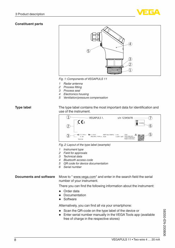
4
5
123
Fig. 1: Components of VEGAPULS 111 Radar antenna2 Processfitting3 Process seal4 Electronics housing5 Ventilation/pressure compensation
Thetypelabelcontainsthemostimportantdataforidentificationanduse of the instrument.
0044
12...35V 4...20mAIP66/IP67, TYPE 4x0...8m
123456
1
5
6
7
2
3 2020www.vega.com77761 SCHILTACH,Made in Germany
VEGAPULS 1. s/n 12345678
MWP 3bar (300kPa) PVDF
L=5m1½ NPT / 1 NPT
TAG1234
Fig. 2: Layout of the type label (example)1 Instrument type2 Field for approvals3 Technical data4 Bluetooth access code5 QR code for device documentation6 Serial number
Move to " www.vega.com"andenterinthesearchfieldtheserialnumber of your instrument. Thereyoucanfindthefollowinginformationabouttheinstrument:
• Order data• Documentation• Software
Alternatively,youcanfindallviayoursmartphone:
• Scan the QR-code on the type label of the device or• Enter serial number manually in the VEGA Tools app (available
free of charge in the respective stores)
Constituent parts
Type label
Documents and software

9
3 Product description
VEGAPULS 11 • Two-wire 4 … 20 mA
5835
0-EN
-200
806
3.2 Principle of operationVEGAPULS 11 is a radar sensor for non-contact, continuous level measurement. It is suitable for liquids and solids in practically all industries.
The instrument emits a continuous, frequency-modulated radar signal throughitsantenna.Theemittedsignalisreflectedbythemediumandreceivedbytheantennaasanechowithmodifiedfrequency.Thefrequency change is proportional to the distance and is converted into the level.
3.3 AdjustmentDevices with integrated Bluetooth module can be adjusted wirelessly via standard adjustment tools:
• Smartphone/tablet (iOS or Android operating system)• PC/notebook with Bluetooth USB adapter (Windows operating
system)
1 3
2
Fig. 3: Wireless connection to standard operating devices with integrated Bluetooth LE1 Sensor2 Smartphone/Tablet3 Bluetooth USB adapter4 PC/Notebook
3.4 Packaging, transport and storageYour instrument was protected by packaging during transport. Its capacity to handle normal loads during transport is assured by a test based on ISO 4180.The packaging consists of environment-friendly, recyclable card-board. For special versions, PE foam or PE foil is also used. Dispose of the packaging material via specialised recycling companies.
Transport must be carried out in due consideration of the notes on the transport packaging. Nonobservance of these instructions can cause damage to the device.
Application area
Functional principle
Wireless adjustment
Packaging
Transport
10
3 Product description
VEGAPULS 11 • Two-wire 4 … 20 mA
58350-EN-200806
The delivery must be checked for completeness and possible transit damage immediately at receipt. Ascertained transit damage or con-cealed defects must be appropriately dealt with.
Up to the time of installation, the packages must be left closed and stored according to the orientation and storage markings on the outside.Unless otherwise indicated, the packages must be stored only under the following conditions:
• Not in the open• Dry and dust free• Not exposed to corrosive media• Protected against solar radiation• Avoiding mechanical shock and vibration
• Storage and transport temperature see chapter " Supplement - Technical data - Ambient conditions"
• Relative humidity 20 … 85 %
3.5 AccessoriesScrewedflangesareavailableindifferentversionsaccordingtothefollowing standards: DIN 2501, EN 1092-1, BS 10, ASME B 16.5, JIS B 2210-1984, GOST 12821-80.
Welded sockets are used to connect the devices to the process.Threaded adapters enable simple adaptation of devices with stand-ardthreadedfittings,e.g.toprocess-sidehygieneconnections.
The mounting accessories are used for stable mounting of the device at the measuring point. The parts are available in various versions and sizes.
Transport inspection
Storage
Storage and transport temperature
Flanges
Welded sockets and adapters
Mounting accessories
11
4 Mounting
VEGAPULS 11 • Two-wire 4 … 20 mA
5835
0-EN
-200
806
4 Mounting
4.1 General instructionsThe instrument is suitable for standard and extended ambient condi-tions acc. to DIN/EN/IEC/ANSI/ISA/UL/CSA 61010-1. It can be used indoors as well as outdoors.
Note:For safety reasons, the instrument must only be operated within the permissibleprocessconditions.Youcanfinddetailedinformationonthe process conditions in chapter " Technical data" of the operating instructions or on the type label.
Hence make sure before mounting that all parts of the instrument ex-posed to the process are suitable for the existing process conditions.These are mainly:
• Active measuring component• Processfitting• Process seal
Process conditions in particular are:
• Process pressure• Process temperature• Chemical properties of the medium• Abrasionandmechanicalinfluences
Protect your instrument against moisture ingress through the following measures:
• Use a suitable connection cable (see chapter " Connecting to power supply")
• Tighten the cable gland or plug connector• Lead the connection cable downward in front of the cable entry or
plug connector
This applies mainly to outdoor installations, in areas where high humidity is expected (e.g. through cleaning processes) and on cooled or heated vessels.
Note:Make sure that during installation or maintenance no moisture or dirt can get inside the instrument.To maintain the housing protection, make sure that the housing lid is closed during operation and locked, if necessary.
4.2 Mounting instructionsRadar sensors for level measurement emit electromagnetic waves. The polarization is the direction of the electrical component of these waves.The polarization direction is marked on the housing, see following drawing:
Ambient conditions
Process conditions
Protection against mois-ture
Polarisation

12
4 Mounting
VEGAPULS 11 • Two-wire 4 … 20 mA
58350-EN-200806
1
Fig. 4: Position of the polarisation1 Marking of the polarisation
Note:When the housing is rotated, the direction of polarization changes andhencetheinfluenceofthefalseechoonthemeasuredvalue.Please keep this in mind when mounting or making changes later.
When mounting the device, keep a distance of at least 200 mm (7.874 in) from the vessel wall. If the device is installed in the center of dished or round vessel tops, multiple echoes can arise. However, these can be suppressed by an appropriate adjustment (see chapter " Set up"). If you cannot maintain this distance, you should carry out a false signal suppression during setup. This applies particularly if buildup on the vessel wall is expected. In such cases, we recommend repeating the false signal suppression at a later date with existing buildup.
> 200 mm(7.87")
Fig. 5: Mounting of the radar sensor on round vessel tops
In vessels with conical bottom it can be advantageous to mount the device in the centre of the vessel, as measurement is then possible down to the bottom.
Installation position

13
4 Mounting
VEGAPULS 11 • Two-wire 4 … 20 mA
5835
0-EN
-200
806
Fig. 6: Mounting of the radar sensor on vessels with conical bottom
The centre of the antenna lens is the beginning of the measuring range and at the same time the reference plane for the min./max. adjustment, see following diagram:
1Fig. 7: Reference plane1 Reference plane
Donotmounttheinstrumentsinorabovethefillingstream.Makesurethatyoudetectthemediumsurface,nottheinflowingproduct.
Fig.8:Mountingoftheradarsensorwithinflowingmedium
With threaded connection, the antenna end should protrude at least 5 mm (0.2 in) out of the nozzle.
Reference plane
Inflowingmedium
Threaded socket und socket piece

14
4 Mounting
VEGAPULS 11 • Two-wire 4 … 20 mA
58350-EN-200806
ca. 5
mm
Fig. 9: Thread mounting
Ifthereflectivepropertiesofthemediumaregood,youcanmountVEGAPULS 11 on sockets longer than the antenna. The socket end should be smooth and burr-free, if possible also rounded. Youwillfindrecommendedvaluesforsocketheightsinthefollowingillustration or the table. The values come from typical applications. Deviating from the proposed dimensions, also longer sockets are possible, however the local conditions must be taken into account.
d
h
Fig. 10: Socket mounting
Socket diameter d Socket length h
40 mm 1½" ≤150mm ≤5.9in
50 mm 2" ≤200mm ≤7.9in
80 mm 3" ≤300mm ≤11.8in
100 mm 4" ≤400mm ≤15.8in
150 mm 6" ≤600mm ≤23.6in
Note:When mounting on longer nozzles, we recommend carrying out a false signal suppression (see chapter " Parameter adjustment").
The mounting location of the radar sensor should be a place where no otherequipmentorfixturescrossthepathoftheradarsignals.Vessel installations, such as e.g. ladders, limit switches, heating spi-rals, struts, etc., can cause false echoes and impair the useful echo. Make sure when planning your measuring point that the radar sensor has a " clear view" to the measured product. In case of existing vessel installations, a false signal suppression should be carried out during setup.If large vessel installations such as struts or supports cause false echoes, these can be attenuated through supplementary measures. Small,inclinedsheetmetalbafflesabovetheinstallations"scatter" theradarsignalsandpreventdirectinterferingreflections.
Vessel installations

15
4 Mounting
VEGAPULS 11 • Two-wire 4 … 20 mA
5835
0-EN
-200
806
Fig.11:Coverflat,large-areaprofileswithdeflectors
In liquids, direct the device as perpendicular as possible to the me-dium surface to achieve optimum measurement results.
Fig. 12: Alignment in liquids
If there are agitators in the vessel, a false signal suppression should be carried out with the agitators in motion. This ensures that the interferingreflectionsfromtheagitatorsaresavedwiththebladesindifferentpositions.
Fig. 13: Agitators
Throughtheactionoffilling,stirringandotherprocessesinthevessel,compact foams which considerably damp the emitted signals may form on the medium surface.If foams lead to measurement errors, you should use the biggest pos-sible radar antennas or sensors with guided radar.
4.3 Measurement setup - FlowIn general, the following must be observed while mounting the device:
Orientation
Agitators
Foam generation

16
4 Mounting
VEGAPULS 11 • Two-wire 4 … 20 mA
58350-EN-200806
• Mounting the sensor on the upstream or inlet side• Installationinthecentreoftheflumeandverticaltotheliquid
surface• DistancetotheoverfallorificeorVenturiflume• Min. distance to the max. height of damming for optimum accu-
racy: 250 mm (9.843 in) 1)
Detailed project planning data can be found at the channel manufac-turers and in the technical literature.Thefollowingexamplesserveasanoverviewforflowmeasurement.
3 ... 4 hmax
90°
2 3
1
h max
≥ 2
x h m
ax
90°
42 3
≥ 25
0 m
m(9
.84"
)
≥ 25
0 m
m(9
.84"
)
Fig.14:Flowmeasurementwithrectangularflume:hmax.=max.fillingoftherectangularflume1 Overfallorifice(sideview)2 Upstream water3 Tailwater4 Overfallorifice(viewfromtailwater)
Rectangular overfall
1) At smaller distances the measuring accuracy is reduced, see "Technical data".

17
4 Mounting
VEGAPULS 11 • Two-wire 4 … 20 mA
5835
0-EN
-200
806
2
3 ... 4 x hmax
90°
hmax
B1
≥ 25
0 m
m(9
.84"
)
Fig.15:FlowmeasurementwithKhafagi-Venturiflume:hmax.=max.fillingoftheflume;B=tightestconstrictionintheflume1 Position sensor2 Venturiflume
Khafagi-Venturiflume
18
5 Connecting to power supply
VEGAPULS 11 • Two-wire 4 … 20 mA
58350-EN-200806
5 Connecting to power supply
5.1 Preparing the connectionAlways keep in mind the following safety instructions:
• Carryoutelectricalconnectionbytrained,qualifiedpersonnelauthorised by the plant operator
Warning:Only connect or disconnect in de-energized state.
Thedataforpowersupplyarespecifiedinchapter"Technical data".
Note:Power the instrument via an energy-limited circuit (power max. 100 W) acc. to IEC 61010-1, e.g.
• Class 2 power supply unit (acc. to UL1310)• SELV power supply unit (safety extra-low voltage) with suitable
internal or external limitation of the output current
Keepinmindthefollowingadditionalfactorsthatinfluencetheoperat-ing voltage:
• Lower output voltage of the power supply unit under nominal load (e.g. with a sensor current of 20.5 mA or 22 mA in case of fault)
• Influenceofadditionalinstrumentsinthecircuit(seeloadvaluesinchapter " Technical data")
Use cable with round cross section for instruments with housing and cablegland.Toensurethesealeffectofthecablegland(IPprotectionrating),findoutwhichcableouterdiameterthecableglandissuitablefor.The instrument is connected with standard two-wire cable.If electromagnetic interference is expected which is above the test values of EN 61326-1 for industrial areas, shielded cable should be used.
Note:If the temperatures are too high, the cable insulation can be dam-aged. Hence keep apart from the ambient temperature also the self-heating of the instrument for the temperature resistance of the cable in the connection compartment in mind 2).
We recommend to connect the cable screening to ground potential at one end on the supply side when using shielded cable.
Metric threadsIn the case of instrument housings with metric thread, the cable gland is screwed in at the factory. It is sealed with plastic plugs as transport protection.
Safety instructions
Voltage supply
Connection cable
Cable screening and grounding
Cable gland
2) Withanambienttemperature≥50°C(122°F)theconnectioncableshouldbesuitableforatemperaturewhichisatleast20°C(36°F)higher.

19
5 Connecting to power supply
VEGAPULS 11 • Two-wire 4 … 20 mA
5835
0-EN
-200
806
You have to remove this plug before electrical connection.
NPT threadIn the case of instrument housings with self-sealing NPT threads, it is not possible to have the cable entry screwed in at the factory. The cable gland is therefore covered with a red dust protection cap as transport protection.
Note:To ensure the housing protection class, you must replace this protec-tive cap with an approved NPT cable gland before setup.
Note:Do not use grease when screwing in the NPT cable gland or a conduit steel pipe.
Maximum torque see chapter " Technical data".
5.2 ConnectingThe voltage supply and signal output are connected via the spring-loaded terminals in the housing.
Note:Fixedconductorsandflexibleconductorswithferrulescanbeinserteddirectlyintotheterminalopenings.Inthecaseofflexibleconductors for opening the terminals, use a screwdriver (3 mm blade width) to push the actuator lever away from the terminal opening. When released, the terminals are closed again.
Fig. 16: Connection
Connection technology

20
5 Connecting to power supply
VEGAPULS 11 • Two-wire 4 … 20 mA
58350-EN-200806
Youcanfindfurtherinformationonthemax.wirecross-sectionunder" Technical data - Electromechanical data".
Connect the instrument according to the following wiring plan.
5.3 Wiring plan
(+)1 2(-)
1
Fig. 17: Connection compartment VEGAPULS 111 Voltagesupply,signaloutput
5.4 Switch-on phaseAfter connection to the power supply, the device carries out a self-test:
• Internal check of the electronics• Output signal is set to failure
The current measured value is then output on the signal cable.
Connecting
Electronics and connec-tion compartment

21
6 Access protection
VEGAPULS 11 • Two-wire 4 … 20 mA
5835
0-EN
-200
806
6 Access protection
6.1 Bluetooth radio interfaceDevices with a Bluetooth radio interface are protected against un-wanted access from outside. This means that only authorized persons can receive measured and status values and change device settings via this interface.
A Bluetooth access code is required to establish Bluetooth com-munication via the adjustment tool (smartphone/tablet/notebook). This code must be entered once when Bluetooth communication is establishedforthefirsttimeintheadjustmenttool.Itisthenstoredinthe adjustment tool and does not have to be entered again.The Bluetooth access code is individual for each device. It is printed on the device housing and is also supplied with the device in the infor-mation sheet " PINs and Codes". It can be changed by the user after thefirstconnectionhasbeenestablished.IftheBluetoothaccesscode has not been entered correctly, a new entry can only be made after a waiting period has elapsed. The waiting time increases with each additional incorrect entry.
The emergency Bluetooth access code enables Bluetooth communi-cation to be established in the event that the Bluetooth access code is no longer known. It can't be changed. The emergency Bluetooth access code can be found in information sheet " Access protection". If this document is lost, the emergency Bluetooth access code can be retrieved from your personal contact person after legitimation. The storage and transmission of Bluetooth access codes is always encrypted (SHA 256 algorithm).
6.2 Protection of the parameterizationThe settings (parameters) of the device can be protected against un-wanted changes. The parameter protection is deactivated on delivery, all settings can be made.
To protect the parameterization, the device can be locked by the user with the aid of a freely selectable device code. The settings (param-eters) can then only be read out, but not changed. The device code is also stored in the adjustment tool. However, unlike the Bluetooth access code, it must be re-entered for each unlock. When using the adjustment app or DTM, the stored device code is then suggested to the user for unlocking.
The emergency device code allows unlocking the device in case the device code is no longer known. It can't be changed. The emergency device code can also be found on the supplied information sheet " Ac-cess protection". If this document is lost, the emergency device code can be retrieved from your personal contact person after legitimation. The storage and transmission of the device codes is always encrypt-ed (SHA 256 algorithm).
Bluetooth access code
Emergency Bluetooth unlock code
Device code
Emergency device code

22
6 Access protection
VEGAPULS 11 • Two-wire 4 … 20 mA
58350-EN-200806
6.3 Storing the codes in myVEGAIf the user has a " myVEGA" account, then the Bluetooth access code as well as the device code are additionally stored in his account under " PINs and Codes".Thisgreatlysimplifiestheuseofadditionaladjust-ment tools, as all Bluetooth access and device codes are automati-cally synchronized when connected to the " myVEGA" account

23
7 Setup with smartphone/tablet (Bluetooth)
VEGAPULS 11 • Two-wire 4 … 20 mA
5835
0-EN
-200
806
7 Setup with smartphone/tablet (Bluetooth)
7.1 PreparationsMake sure that your smartphone/tablet meets the following system requirements:
• Operating system: iOS 8 or newer• Operating system: Android 5.1 or newer• Bluetooth 4.0 LE or newer
Download the VEGA Tools app from the " Apple App Store", " Goog-le Play Store" or " Baidu Store" to your smartphone or tablet.
Make sure that the VEGAPULS 11 is activated, see chapter " Operat-ingmodus,activatedevice".
7.2 ConnectingStart the adjustment app and select the function " Setup". The smart-phone/tablet searches automatically for Bluetooth-capable instru-ments in the area. The message " Connecting …" is displayed. The devices found are listed and the search is automatically contin-ued.Select the requested instrument in the device list.
Whenestablishingtheconnectionforthefirsttime,theoperatingtoolandthesensormustauthenticateeachother.Afterthefirstcorrectauthentication, each subsequent connection is made without a new authentication query.
For authentication, enter the 6-digit Bluetooth access code in the nextmenuwindow.Youcanfindthecodeontheoutsideofthedevicehousing and on the information sheet " Pins and Codes" in the device packaging.
Fig. 18: Enter Bluetooth access code
Note:If an incorrect code is entered, the code can only be entered again after a delay time. This time gets longer after each incorrect entry.
The message " Waiting for authentication" is displayed on the smart-phone/tablet.
System requirements
Device activated
Connecting
Authenticate
Enter Bluetooth access code

24
7 Setup with smartphone/tablet (Bluetooth)
VEGAPULS 11 • Two-wire 4 … 20 mA
58350-EN-200806
After connection, the sensor adjustment menu is displayed on the respective adjustment tool.If the Bluetooth connection is interrupted, e.g. due to a too large distance between the two devices, this is displayed on the adjustment tool. The message disappears when the connection is restored.
Parameter adjustment of the device is only possible if the parameter protection is deactivated. When delivered, parameter protection is deactivated by default and can be activated at any time.It is recommended to enter a personal 6-digit device code. To do this, go to menu " Extended functions", " Access protection", menu item " Protection of the parameter adjustment".
7.3 Parameter adjustmentThe sensor adjustment menu is divided into two areas, which are arranged next to each other or one below the other, depending on the adjustment tool.
• Navigation section• Menu item display
The selected menu item can be recognized by the colour change.
Fig. 19: Example of an app view - Setup measured values
Entertherequestedparametersandconfirmviathekeyboardortheeditingfield.Thesettingsarethenactiveinthesensor.Close the app to terminate connection.
Connected
Change device code
Enter parameters

25
8 Setup with PC/notebook (Bluetooth)
VEGAPULS 11 • Two-wire 4 … 20 mA
5835
0-EN
-200
806
8 Setup with PC/notebook (Bluetooth)
8.1 PreparationsMake sure that your PC/notebook meets the following system require-ments:
• Operating system Windows 10• DTM Collection 10/2020 or newer• Bluetooth 4.0 LE or newer
Activate the Bluetooth connection via the project assistant.
Note:Older systems do not always have an integrated Bluetooth LE. In these cases, a Bluetooth USB adapter is required. Activate the Bluetooth USB adapter using the Project Wizard.
After activating the integrated Bluetooth or the Bluetooth USB adapt-er, devices with Bluetooth are found and created in the project tree.
Make sure that the VEGAPULS 11 is activated, see chapter " Operat-ingmodus,activatedevice".
8.2 ConnectingSelect the requested device for the online parameter adjustment in the project tree.
Whenestablishingtheconnectionforthefirsttime,theoperatingtoolandthedevicemustauthenticateeachother.Afterthefirstcorrectauthentication, each subsequent connection is made without a new authentication query.
For authentication, enter in the next menu window the 6-digit Bluetooth access code:
System requirements
Activate Bluetooth con-nection
Device activated
Connecting
Authenticate
Enter Bluetooth access code

26
8 Setup with PC/notebook (Bluetooth)
VEGAPULS 11 • Two-wire 4 … 20 mA
58350-EN-200806
Fig. 20: Enter Bluetooth access code
Youcanfindthecodeontheoutsideofthedevicehousingandontheinformation sheet " PINs and Codes" in the device packaging.
Note:If an incorrect code is entered, the code can only be entered again after a delay time. This time gets longer after each incorrect entry.
The message " Waiting for authentication" is displayed on the PC/notebook.
After connection, the device DTM appears.If the connection is interrupted, e.g. due to a too large distance be-tween device and adjustment tool, this is displayed on the adjustment tool. The message disappears when the connection is restored.
Parameter adjustment of the device is only possible if the parameter protection is deactivated. When delivered, parameter protection is deactivated by default and can be activated at any time.It is recommended to enter a personal 6-digit device code. To do this, go to menu " Extended functions", " Access protection", menu item " Protection of the parameter adjustment".
8.3 Parameter adjustmentFor parameter adjustment of the instrument via a Windows PC, the configurationsoftwarePACTwareandasuitableinstrumentdriver(DTM) according to FDT standard are required. The latest PACTware version as well as all available DTMs are compiled in a DTM Collec-tion. The DTMs can also be integrated into other frame applications according to FDT standard.
Connected
Change device code
Prerequisites
27
8 Setup with PC/notebook (Bluetooth)
VEGAPULS 11 • Two-wire 4 … 20 mA
5835
0-EN
-200
806
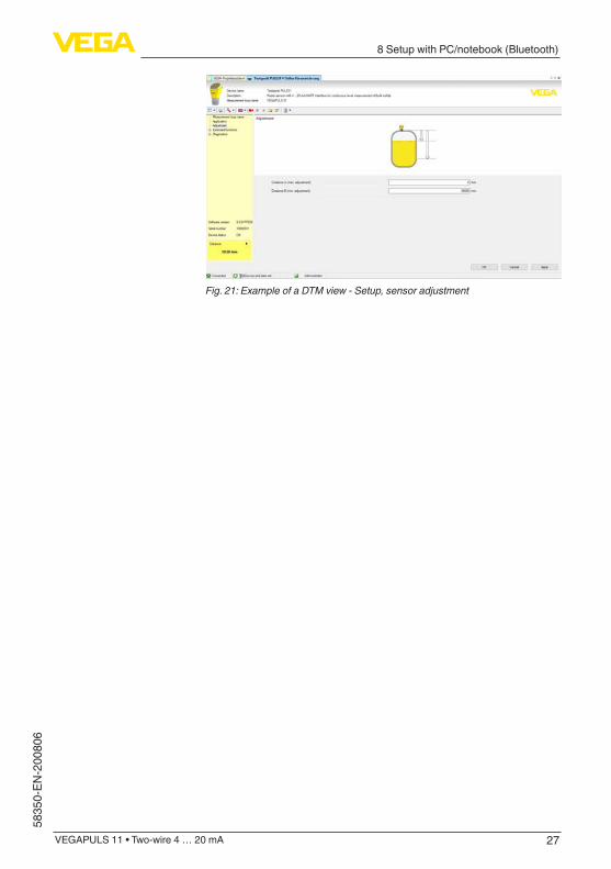
Fig.21:ExampleofaDTMview-Setup,sensoradjustment

28
9 Adjustment menu
VEGAPULS 11 • Two-wire 4 … 20 mA
58350-EN-200806
9 Adjustment menu
9.1 Menu overview
Menu item Selection Basic settings
Measurement loop name
Alphanumeric characters Sensor
Medium LiquidBulk solid
Liquid
Application liquid Storage tank, agitator tank, dos-ing tank, pumping station/pump shaft,rainoverflowbasin,tank/collection basin, plastic tank (measurement through tank top), mobile plastic tank (IBC), level measurement in waters, flowmeasurementflume/over-flow,demonstration
Storage tank
Application bulk solid Silo (slim and high), bunker (large volume), stockpile (point measurement/profiledetection),crusher, demonstration
Silo (slender and high)
Units Distance unit of the deviceTemperature unit of the instru-ment
Distance in mTemperaturein°C
Adjustment Max. adjustment (distance A)Min. adjustment (distance B)
Max. adjustment 8,000 mMin. adjustment 0,000 m
Menu item Selection Basic settings
Damping Integration time 0 s
Current output Output characteristics 4 … 20 mA
Current range Min. current 3.8 mA and max. current 20.5 mA
Reaction when malfunctions occur
Failure mode < 3.6 mA
Linearisation Linearization type Linear
Scaling Scaling sizeScaling unitScaling format
0 % correspond to 0 l100 % correspond to 100 l
Display Menu languageDisplayed valueBacklight
EnglishFilling heightOn
Access protection Bluetooth access code -
Main menu
Extended functions

29
9 Adjustment menu
VEGAPULS 11 • Two-wire 4 … 20 mA
5835
0-EN
-200
806
Menu item Selection Basic settings
Protection of the parameteri-zation
Deactivated
False signal sup-pression
False signal suppression 0 m
Sounded distance to the me-dium
0 m
Reset Delivery status, basic settings -
Mode Mode 1: EU, Albania, Andorra, Azerbaijan, Australia, Bela-rus, Bosnia and Herzegovina, Canada, Liechtenstein, Molda-via, Monaco, Montenegro, New Zealand, Northern Macedonia, Norway, San Marino, Saudi Ara-bia, Serbia, Switzerland, Turkey, Ukraine, United Kingdom, USAMode 2: South Korea, Taiwan,ThailandMode 3: South AfricaMode 4: Russia
Mode 1
Menu item Selection Basic settings
Status Sensor statusMeasured value statusStatus outputStatus additional measured val-ues
-
Echo curve Indication of echo curve -
Peak value indicator Pointer function distance, meas-urement reliability, meas. rate, electronic temperature
-
Measured values Measured valuesAdditional measured valuesOutputs
-
Sensor information Device name, serial number, hardware/software version, de-vice revision, factory calibration date
-
Sensor character-istics
Sensor features from order text -
Simulation Measured valueSimulation value
-
Measured value memory (DTM)
Indication measured value mem-ory from DTM
Diagnostics

30
9 Adjustment menu
VEGAPULS 11 • Two-wire 4 … 20 mA
58350-EN-200806
9.2 Description of the applicationsThis menu item enables you to optimally adapt the sensor to the ap-plication, the place of use and the measuring conditions. The adjust-ment possibilities depend on the selection made under " Medium", " Liquid" or " Bulk solid". The vessels as well as the measuring and process conditions are described in the following as an overview.
With " Liquid", the applications are based on the following features, to which the measuring characteristic of the sensor is adjusted in particular:
Storage tank• Vessel:
– Large volume – Upright cylindrical, horizontal round
• Process/measurement conditions: – Slowfillingandemptying – Smooth medium surface – Multiplereflectionsfromdishedvesselceiling – Condensation
Stirrer vessel• Vessel:
– Large agitator blades of metal – Installationslikeflowbreakers,heatingspirals – Nozzle
• Process/measurement conditions: – Frequent,fasttoslowfillingandemptying – Strongly agitated surface, foam and strong vortex generation – Multiplereflectionsthroughdishedvesselceiling – Condensation, buildup on the sensor
• Further recommendations – False signal suppression with running agitator via adjustment
app or PACTware/DTM
Dosing vessel• Vessel:
– Small vessels• Process/measurement conditions:
– Frequentandfastfilling/emptying – Tight installation situation – Multiplereflectionsthroughdishedvesselceiling – Product buildup, condensate and foam generation
Pumping station/Pump shaft• Process/measurement conditions:
– Partly strongly agitated surface – Installations such as pumps and ladders – Multiplereflectionsthroughflatvesselceiling – Dirt and grease deposits on shaft wall and sensor – Condensation on the sensor
Application
Application - liquid

31
9 Adjustment menu
VEGAPULS 11 • Two-wire 4 … 20 mA
5835
0-EN
-200
806
• Further recommendations – False signal suppression via adjustment app or PACTware/DTM
Overflowbasin• Vessel
– Large volume – Partly installed underground
• Process/measurement conditions: – Partly strongly agitated surface – Multiplereflectionsthroughflatvesselceiling – Condensation, dirt deposits on the sensor – Flooding of the sensor antenna
Vessel/Collecting basin• Vessel:
– Large volume – Upright cylindrical or rectangular
• Process/measurement conditions: – Slowfillingandemptying – Smooth medium surface – Condensation
Plastic tank (measurement through the vessel top)• Process/measurement conditions:
– Measurement through the tank top, if appropriate to the applica-tion
– Condensation on the plastic ceiling – In outdoor facilities, water and snow on vessel top possible
• Further recommendations – With measurement through the tank top false signal suppres-
sion via adjustment app or PACTware/DTM – When measuring through the tank top in outdoor areas protec-
tive roof for the measuring point
Transportable plastic tank (IBC)• Process/measurement conditions:
– Materialandthicknessdifferent – Measurement through the vessel top, if appropriate to the
application – Changedreflectionconditionsaswellasjumpsinmeasured
values when changing vessels• Further recommendations
– With measurement through the tank top false signal suppres-sion via adjustment app or PACTware/DTM
– When measuring through the tank top in outdoor areas protec-tive roof for the measuring point
Gauge measurement in waters• Process/measurement conditions:
– Slow gauge change – Extreme damping of output signal in case of wave generation – Ice and condensation on the antenna possible – Floating debris sporadically on the water surface

32
9 Adjustment menu
VEGAPULS 11 • Two-wire 4 … 20 mA
58350-EN-200806
Flowmeasurementflume/Overfall• Process/measurement conditions:
– Slow gauge change – Smooth to agitated water surface – Measurement often from a short distance with the demand for
accurate measurement results – Ice and condensation on the antenna possible
Demonstration• Applications that are not typical level measurements, e.g. device
tests – Instrument demonstration – Object recognition/monitoring – Fast position changes of a measuring plate during functional
test
With " Bulk solid", the applications are based on the following fea-tures, to which the measuring characteristic of the sensor is adjusted in particular:
Silo (slender and high)• Process/measurement conditions:
– Interferingreflectionsduetoweldseamsonthevessel – Multipleechoes/diffusereflectionsduetounfavourablepouringpositionswithfinegrain
– Varyingpouringpositionsduetooutletfunnelandfillingcone• Further recommendations
– False signal suppression via adjustment app or PACTware/DTM – Alignment of the measurement to the silo outlet
Bunker (large-volume)• Process/measurement conditions:
– Large distance to the medium – Steep angles of repose, unfavourable pouring positions due to outletfunnelandfillingcone
– Diffusereflectionsduetostructuredvesselwallsorinternals – Multipleechoes/diffusereflectionsduetounfavourablepouringpositionswithfinegrain
– Changing signal conditions when large amounts of material slip off
• Further recommendations – False signal suppression via adjustment app or PACTware/DTM
Heap(pointmeasurement/profiledetection)• Process/measurement conditions:
– Measuredvaluejumps,e.g.throughheapprofileandtraverses – Large angles of repose, varying pouring positions – Measurementnearthefillingstream – Sensor mounting on movable conveyor belts
Crusher• Process/measurement conditions:
Application - bulk solid

33
9 Adjustment menu
VEGAPULS 11 • Two-wire 4 … 20 mA
5835
0-EN
-200
806
– Measured value jumps and varying pouring positions, e.g. due totruckfilling
– Fast reaction time – Large distance to the medium – Interferingreflectionsfromfixturesorprotectivedevices
• Further recommendations – False signal suppression via adjustment app or PACTware/DTM
Demonstration• Applications that are not typical level measurements
– Instrument demonstration – Object recognition/monitoring – Measuredvalueverificationwithhighermeasuringaccuracywithreflectionwithoutbulksolids,e.g.viaameasuringplate

34
10 Diagnostics and servicing
VEGAPULS 11 • Two-wire 4 … 20 mA
58350-EN-200806
10 Diagnostics and servicing
10.1 MaintenanceIf the device is used properly, no special maintenance is required in normal operation.
Insomeapplications,buildupontheantennasystemcaninfluencethe measuring result. Depending on the sensor and application, take measures to avoid heavy soiling of the antenna system. If necessary, clean the antenna system in certain intervals.
The cleaning helps that the type label and markings on the instrument are visible.Take note of the following:
• Use only cleaning agents which do not corrode the housings, type label and seals
• Use only cleaning methods corresponding to the housing protec-tion rating
10.2 Rectify faultsThe operator of the system is responsible for taking suitable meas-ures to rectify faults.
Thedeviceoffersmaximumreliability.Nevertheless,faultscanoccurduring operation. These may be caused by the following, e.g.:
• Sensor• Process• Voltage supply• Signal processing
Thefirstmeasuresare:
• Evaluation of fault messages• Checking the output signal• Treatment of measurement errors
A smartphone/tablet with the adjustment app or a PC/notebook with thesoftwarePACTwareandthesuitableDTMofferyoufurthercom-prehensive diagnostic possibilities. In many cases, the causes can be determined in this way and the faults eliminated.
Depending on the reason for the fault and the measures taken, the steps described in chapter " Setup" must be carried out again or must be checked for plausibility and completeness.
Should these measures not be successful, please call in urgent cases the VEGA service hotline under the phone no. +49 1805 858550. The hotline is also available outside normal working hours, seven days a week around the clock.
Maintenance
Precaution measures against buildup
Cleaning
Reaction when malfunc-tion occurs
Causes of malfunction
Faultrectification
Reaction after fault recti-fication
24 hour service hotline

35
10 Diagnostics and servicing
VEGAPULS 11 • Two-wire 4 … 20 mA
5835
0-EN
-200
806
Sinceweofferthisserviceworldwide,thesupportisprovidedinEnglish. The service itself is free of charge, the only costs involved are the normal call charges.
10.3 Diagnosis, fault messagesConnect a multimeter in the suitable measuring range according to the wiring plan. The following table describes possible errors in the current signal and helps to eliminate them:
Error Cause Rectification
4 … 20 mA signal not stable Fluctuating measured value Set damping
4 … 20 mA signal missing Electrical connection faulty Check connection, correct, if necessary
Voltage supply missing Check cables for breaks; repair if nec-essary
Operating voltage too low, load resist-ance too high
Check, adapt if necessary
Current signal greater than 22 mA, less than 3.6 mA
Sensor electronics defective Replace device or send in for repair de-pending on device version
The LED illuminated ring on the device (see chapter " Configuration") indicates the operating status of the device. This enables simple on-site diagnosis without the need for tools.
Colour 3) Permanent light Flashing
Green Operation without interference Message " Maintenance required" is displayed
Yellow Operation without interference -
Red Operation with interference Message acc. to to NE 107 " Function check", " Outofspecification" or " Simu-lation state" is displayed
10.4 Status messages according to NE 107The instrument features self-monitoring and diagnostics according to NE 107 and VDI/VDE 2650. In addition to the status messages in the following tables there are more detailed error messages available under the menu item " Diagnostics" via the respective adjustment module.
The status messages are divided into the following categories:
• Failure• Function check• Outofspecification• Maintenance required
and explained by pictographs:
4 … 20 mA signal
LED illuminated ring
Status messages
3) Adjustable via VEGA Tools app or PACTware/DTM

36
10 Diagnostics and servicing
VEGAPULS 11 • Two-wire 4 … 20 mA
58350-EN-200806
41 2 3Fig. 22: Pictographs of the status messages1 Failure - red2 Outofspecification-yellow3 Function check - orange4 Maintenance required - blue
Failure: Due to a malfunction in the instrument, a fault message is output. This status message is always active. It cannot be deactivated by the user.Function check: The instrument is being worked on, the measured value is temporarily invalid (for example during simulation). This status message is inactive by default.Outofspecification: The measured value is unreliable because an instrumentspecificationwasexceeded(e.g.electronicstemperature).This status message is inactive by default.Maintenance required:Duetoexternalinfluences,theinstrumentfunctionislimited.Themeasurementisaffected,butthemeasuredvalue is still valid. Plan in maintenance for the instrument because a failure is expected in the near future (e.g. due to buildup). This status message is inactive by default.
CodeText message
Cause Rectification
F013no measured value available
No measured value in the switch-on phase or during operation
Check or correct installation and/or pa-rameter settingsClean the antenna system
F017Adjustment span too small
Adjustmentnotwithinspecification Change adjustment according to the limit values(differencebetweenmin.andmax.≥10mm)
F025Error in the lineariza-tion table
Index markers are not continuously rising, for example illogical value pairs
Check linearization tableDelete table/Create new
F036No operable software
Checksum error if software update failed or aborted
Repeat software updateSend instrument for repair
F040Error in the electronics
Limit value exceeded in signal processingHardware error
Restart instrumentSend instrument for repair
F080General software error
General software error Restart instrument
Failure

37
10 Diagnostics and servicing
VEGAPULS 11 • Two-wire 4 … 20 mA
5835
0-EN
-200
806
CodeText message
Cause Rectification
F105Determine measured value
The instrument is still in the start phase, the measured value could not yet be de-termined
Wait for the end of the switch-on phaseDuration up to 3 minutes depending on the measurement environment and pa-rameter settings
F260Error in the calibration
Checksum error in the calibration valuesError in the EEPROM
Send instrument for repair
F261Error in the instrument settings
Error during setupFalse signal suppression faultyError when carrying out a reset
Repeat setupCarry out a reset
F265Measurement function disturbed
Program sequence of the measuring func-tion disturbed
Device restarts automatically
CodeText message
Cause Rectification
C700Simulation active
A simulation is active Finish simulationWait for the automatic end after 60 mins.
CodeText message
Cause Rectification
S600Impermissible electron-ics temperature
Temperature of the electronics in the non-specifiedrange
Check ambient temperatureInsulate electronics
S601Overfilling
Dangerofvesseloverfilling MakesurethatthereisnofurtherfillingCheck level in the vessel
S603Impermissible operating voltage
Terminal voltage too small Check terminal voltage, increase operat-ing voltage
CodeText message
Cause Rectification
M500Error in the delivery status
The data could not be restored during the reset to delivery status
Repeat resetLoadXMLfilewithsensordataintothesensor
M501Error in the delivery status
Hardware error EEPROM Send instrument for repair
M504Error at a device inter-face
Hardware defect Check connectionsExchanging the electronicsSend instrument for repair
Function check
Outofspecification
Maintenance

38
10 Diagnostics and servicing
VEGAPULS 11 • Two-wire 4 … 20 mA
58350-EN-200806
CodeText message
Cause Rectification
M505No echo available
Sensor does not detect an echo during operationAntenna dirty or defective
Clean the antennaUse a more suitable antenna/sensorRemove possible false echoesOptimize sensor position and orientation
M507Error in the instrument settings
Error during setupError when carrying out a resetFalse signal suppression faulty
Carry out reset and repeat setup
M508No executable Bluetooth software
Checksum error in Bluetooth software Carry out software update
M509Software update running
Software update running Waituntilsoftwareupdateisfinished
M510No communication with the main controller
Communication between main electronics and display module disturbed
Check the connection cable to the displaySend instrument for repair
M511Inconsistent software configuration
A software unit requires a software update Carry out software update
10.5 Treatment of measurement errorsThe tables below give typical examples of application-related meas-urement errors.The images in column " Error description" show the actual level as a dashed line and the output level as a solid line.
12
Leve
l
time0
1 Real level2 Level displayed by the sensor
Note:If the output level is constant, the cause could also be the fault setting of the current output to " Hold value". If the level is too low, the reason could be a line resistance that is too high

39
10 Diagnostics and servicing
VEGAPULS 11 • Two-wire 4 … 20 mA
5835
0-EN
-200
806
Liquids: Measurement error at constant level
Fault description Cause Rectification
Measured value shows a too low or too high level
Leve
l
time0
Min./max. adjustment not correct Adapt min./max. adjustment
Incorrect linearization curve Adapt linearization curve
Measured value jumps to-wards 100 %
Leve
l
time0
Due to the process, the amplitude of the level echo sinksA false signal suppression was not car-ried out
Carry out a false signal suppression
Amplitude or position of a false signal has changed (e.g. condensation, build-up); false signal suppression no longer matches actual conditions
Determine the reason for the changed false signals, carry out false signal sup-pression, e.g. with condensation.
Liquids:Measurementerrorduringfilling
Fault description Cause Rectification
Measured value remains un-changedduringfilling
Leve
l
time0
False signals in the close range too big or level echo too smallStrong foam or vortex generationMax. adjustment not correct
Eliminate false signals in the close rangeCheck measuring point: Antenna should protrude out of the threaded mounting socket, possible false echoes through flangesocket?Remove contamination on the antennaIn case of interferences due to instal-lations in the close range, change polarisation directionCreate a new false signal suppressionAdapt max. adjustment
Measured value jumps to-wards0%duringfilling
Leve
l
time0
The level echo cannot be distinguished from the false signal at a false signal po-sition (jumps to multiple echo)
In case of interferences due to instal-lations in the close range: Change polarisation directionChose a more suitable installation po-sition
Measured value jumps to-wards100%duringfilling
Leve
l
time0
Due to strong turbulence and foam gen-erationduringfilling,theamplitudeofthe level echo sinks. Measured value jumps to false signal
Carry out a false signal suppression

40
10 Diagnostics and servicing
VEGAPULS 11 • Two-wire 4 … 20 mA
58350-EN-200806
Fault description Cause Rectification
Measured value jumps spo-radically to 100 % during filling
Level
time0
Varying condensation or contamination on the antenna
Carry out a false signal suppression or increase false signal suppression with condensation/contamination in the close range by editing
Measured value jumps to ≥100%or0mdistance
Leve
l
time0
Level echo is no longer detected in the close range due to foam genera-tion or false signals in the close range. Thesensorgoesintooverfillprotectionmode. The max. level (0 m distance) as well as the status message " Overfillprotection" are output.
Check measuring point: Antenna should protrude out of the threaded mounting socket, possible false echoes through flangesocket?Remove contamination on the antenna
Liquids: Measurement error during emptying
Fault description Cause Rectification
Measured value remains un-changed in the close range during emptying
Leve
l
time0
False signal larger than the level echoLevel echo too small
Check measuring point: Antenna should protrude out of the threaded mounting socket, possible false echoes through flangesocket?Remove contamination on the antennaIn case of interferences due to instal-lations in the close range: Change polarisation directionAfter eliminating the false signals, the false signal suppression must be de-leted. Carry out a new false signal suppression
Measured value jumps spo-radically towards 100 % during emptying
Leve
l
time0
Varying condensation or contamination on the antenna
Carry out false signal suppression or in-crease false signal suppression in the close range by editingWith bulk solids, use radar sensor with purging air connection
Bulk solids: Measurement error at constant level
Fault description Cause Rectification
Measured value shows a too low or too high level
Leve
l
time0
Min./max. adjustment not correct Adapt min./max. adjustment
Incorrect linearization curve Adapt linearization curve

41
10 Diagnostics and servicing
VEGAPULS 11 • Two-wire 4 … 20 mA
5835
0-EN
-200
806
Fault description Cause Rectification
Measured value jumps to-wards 100 %
Leve
l
time0
Due to the process, the amplitude of the product echo decreasesA false signal suppression was not car-ried out
Carry out a false signal suppression
Amplitude or position of a false signal has changed (e.g. condensation, build-up); false signal suppression no longer matches actual conditions
Determine the reason for the changed false signals, carry out false signal sup-pression, e.g. with condensation.
Bulksolids:Measurementerrorduringfilling
Fault description Cause Rectification
Measured value jumps to-wards0%duringfilling
Leve
l
time0
The level echo cannot be distinguished from the false signal at a false signal po-sition (jumps to multiple echo)
Remove/reduce false signal: minimize interfering installations by changing the polarization directionChose a more suitable installation po-sition
Transversereflectionfromanextractionfunnel, amplitude of the transverse re-flectionlargerthanthelevelecho
Direct sensor to the opposite fun-nelwall,avoidcrossingwiththefillingstream
Measuredvaluefluctuatesaround 10 … 20 %
Leve
l
time0
Various echoes from an uneven medi-um surface, e.g. a material cone
Check parameter "Material Type" and adapt, if necessaryOptimize installation position and sen-sor orientation
Reflectionsfromthemediumsurfaceviathevesselwall(deflection)
Select a more suitable installation po-sition, optimize sensor orientation, e.g. with a swivelling holder
Measured value jumps spo-radically to 100 % during filling
Level
time0
Changing condensation or contamina-tion on the antenna
Carry out a false signal suppression or increase false signal suppression with condensation/contamination in the close range by editing
Bulk solids: Measurement error during emptying
Fault description Cause Rectification
Measured value remains un-changed in the close range during emptying
Leve
l
time0
False signal greater than level echo or level echo too small
Eliminate false signals in the close range. Check: Antenna must protrude out of the nozzleRemove contamination on the antennaMinimize interfering installations in the close range by changing the polariza-tion directionAfter eliminating the false signals, the false signal suppression must be de-leted. Carry out a new false signal suppression

42
10 Diagnostics and servicing
VEGAPULS 11 • Two-wire 4 … 20 mA
58350-EN-200806
Fault description Cause Rectification
Measured value jumps spo-radically towards 100 % during emptying
Leve
l
time0
Changing condensation or contamina-tion on the antenna
Carry out false signal suppression or in-crease false signal suppression in the close range by editing
Measuredvaluefluctuatesaround 10 … 20 %
Leve
l
time0
Various echoes from an uneven medi-um surface, e.g. an extraction funnel
Check parameter "Material Type" and adapt, if necessary
Reflectionsfromthemediumsurfaceviathevesselwall(deflection)
Optimize installation position and sen-sor orientation
10.6 Software updateThe device software is updated via Bluetooth.The following components are required:
• Instrument• Voltage supply• PC/notebook with PACTware/DTM and Bluetooth USB adapter• CurrentinstrumentsoftwareasfileYoucanfindthecurrentinstrumentsoftwareaswellasdetailedinfor-mation on the procedure in the download area of our homepage.
Caution:Instruments with approvals can be bound to certain software versions. Thereforemakesurethattheapprovalisstilleffectiveafterasoftwareupdate is carried out.Youcanfinddetailedinformationinthedownloadareaonourhome-page.
10.7 How to proceed if a repair is necessaryYoucanfindaninstrumentreturnformaswellasdetailedinformationabout the procedure in the download area of our homepage. By doing this you help us carry out the repair quickly and without having to call back for needed information.In case of repair, proceed as follows:
• Printandfilloutoneformperinstrument• Clean the instrument and pack it damage-proof• Attach the completed form and, if need be, also a safety data
sheet outside on the packaging• Ask the agency serving you to get the address for the return ship-
ment.Youcanfindtheagencyonourhomepage.
43
11 Dismount
VEGAPULS 11 • Two-wire 4 … 20 mA
5835
0-EN
-200
806
11 Dismount
11.1 Dismounting stepsWarning:Before dismounting, be aware of dangerous process conditions such as e.g. pressure in the vessel or pipeline, high temperatures, cor-rosive or toxic media etc.
Take note of chapters " Mounting" and " Connecting to voltage sup-ply" and carry out the listed steps in reverse order.
11.2 DisposalThe device is made of recyclable materials. For this reason, it should be disposed of by a specialist recycling company. Observe the ap-plicable national regulations.

44
12Certificatesandapprovals
VEGAPULS 11 • Two-wire 4 … 20 mA
58350-EN-200806
12 Certificatesandapprovals
12.1 Radio licensesRadarThe device has been tested and approved in accordance with the cur-renteditionoftheapplicablecountry-specificnormsorstandards.Regulations for use can be found in the document " Regulations for radar level measuring instruments with radio licenses" on our home-page.
BluetoothThe Bluetooth radio module in the device has been tested and approved according to the current edition of the applicable country-specificnormsorstandards.Theconfirmationsaswellasregulationsforusecanbefoundinthedocument " Radio licenses" supplied or on our homepage.
12.2 EU conformityThedevicefulfilsthelegalrequirementsoftheapplicableEUdirec-tives.ByaffixingtheCEmarking,weconfirmtheconformityoftheinstrument with these directives.The EU conformity declaration can be found on our homepage.
12.3 Environment management systemProtection of the environment is one of our most important duties. That is why we have introduced an environment management system with the goal of continuously improving company environmental pro-tection.TheenvironmentmanagementsystemiscertifiedaccordingtoDINENISO14001.Pleasehelpusfulfilthisobligationbyobserv-ing the environmental instructions in chapters " Packaging,transportand Lagestoragerung", " Disposal" of these operating instructions.

45
13 Supplement
VEGAPULS 11 • Two-wire 4 … 20 mA
5835
0-EN
-200
806
13 Supplement
13.1 Technical dataNote for approved instrumentsThe technical data in the respective safety instructions which are included in delivery are valid for approvedinstruments(e.g.withExapproval).Thesedatacandifferfromthedatalistedherein,forexample regarding the process conditions or the voltage supply.All approval documents can be downloaded from our homepage.
Materials and weightsMaterials, wetted parts
Ʋ Antenna,processfitting PVDF Ʋ Process seal FKM
Materials, non-wetted parts Ʋ Housing Plastic PBT (Polyester) Ʋ Housing seals O-rings (silicone) Ʋ Cable gland PA Ʋ Sealing, cable gland NBR Ʋ Blind plug, cable gland PA
Weight 0.7 kg (1.543 lbs)
TorquesMax. torque mounting boss 7 Nm (5.163 lbf ft)Max. torque for NPT cable glands and Conduit tubes
10 Nm (7.376 lbf ft)
Input variableMeasured variable The measured variable is the distance between the
antenna edge of the sensor and the medium surface. The antenna edge is also the reference plane for the measurement.
2
1
Fig. 23: Data of the input variable1 Reference plane2 Measuredvariable,max.measuringrange

46
13 Supplement
VEGAPULS 11 • Two-wire 4 … 20 mA
58350-EN-200806
Max. measuring range 4) 8 m (26.25 ft)Recommended measuring range 5) up to 5 m (16.4 ft)blocking distance 6)
Ʋ Modes 1, 2, 4 0 mm (0 in) Ʋ Mode 3 ≥250mm(9.843in)
Switch-on phaseStart-up time with operating voltage UB < 15 sStarting current (for run-up time) ≤3.6mA
Output variableOutput signal 4 … 20 mARange of the output signal 3.8 … 20.5 mA (default setting)Signal resolution 0.3 µAResolution, digital 1 mm (0.039 in)Fault signal, current output (adjustable) ≤3.6mA,>=21mA,lastvalidmeasuredvalueMax. output current 22 mALoad See load resistance under Power supplyStarting current ≤3.6mA;≤10mAfor5msafterswitchingonDamping (63 % of the input variable), adjustable
0 … 999 s
Deviation (according to DIN EN 60770-1)Process reference conditions according to DIN EN 61298-1
Ʋ Temperature +18…+30°C(+64…+86°F) Ʋ Relative humidity 45 … 75 % Ʋ Air pressure 860 … 1060 mbar/86 … 106 kPa (12.5 … 15.4 psig)
Installation reference conditions Ʋ Distance to installations >200mm(7.874in) Ʋ Reflector Flatplatereflector Ʋ Falsereflections Biggest false signal, 20 dB smaller than the useful signal
Deviation with liquids ≤5mm(meas.distance>0.25m/0.8202ft)Non-repeatability 7) ≤5mmDeviation with bulk solids The values depend to a great extent on the application.
Bindingspecificationsarethusnotpossible.
4) Depending on application and medium5) With bulk solids6) Depending on the operating conditions7) Already included in the meas. deviation

47
13 Supplement
VEGAPULS 11 • Two-wire 4 … 20 mA
5835
0-EN
-200
806
0,25 m (0.8202 ft)
10 mm (0.3937 in)
- 10 mm (- 0.3937 in)
5 mm (0.1969 in)
- 5 mm (- 0.1969 in)
0
1 2
Fig. 24: Deviation under reference conditions 8)
1 Antennaedge,referenceplane2 Recommended measuring range
VariablesinfluencingmeasurementaccuracyTemperature drift - Current output <0.03%/10Krelatingtothe16mAspanor≤0.3%Deviation in the current output due to digital/analogue conversion
< 15 µA
Additional deviation through electromagnetic interference Ʋ According to NAMUR NE 21 < 80 µA Ʋ According to EN 61326-1 None Ʋ According to IACS E10 (shipbuilding)/IEC 60945
< 250 µA
Characteristics and performance dataMeasuring frequency W-band (80 GHz technology)Measuring cycle time 9) ≤250msStep response time 10) ≤3sBeam angle 11) 8°Emitted HF power (depending on the parameter setting) 12)
Ʋ Average spectral transmission power density
-3 dBm/MHz EIRP
Ʋ Max. spectral transmission power density
+34 dBm/50 MHz EIRP
Ʋ Max. power density at a distance of 1 m
< 3 µW/cm²
Ambient conditionsAmbient temperature -40…+60°C(-40…+140°F)
8) Incaseofdeviationsfromreferenceconditions,theoffsetduetoinstallationcanbeupto+/-4mm.Thisoffsetcan be compensated by the adjustment.
9) With operating voltage UB≥24VDC10) Timespanafterasuddendistancechangefrom1mto5muntiltheoutputsignalreaches90%ofthefinalvalueforthefirsttime(IEC61298-2).ValidwithoperatingvoltageUB≥24VDC.
11)Outsidethespecifiedbeamangle,theenergyleveloftheradarsignalis50%(-3dB)less.12) EIRP: Equivalent Isotropic Radiated Power

48
13 Supplement
VEGAPULS 11 • Two-wire 4 … 20 mA
58350-EN-200806
Storage and transport temperature -40…+80°C(-40…+176°F)
Mechanical environmental conditionsVibrations Class 4M8 acc. to IEC 60271-3-4 (5 g at 4 ... 200 Hz)Impacts (mechanical shock) Class 6M4 acc. to IEC 60271-3-6 (50 g, 2.3 ms)Impact resistance IK07 acc. to IEC 62262
Process conditionsFortheprocessconditions,pleasealsonotethespecificationsonthetypelabel.Thelowestvalue(amount) always applies.Process temperature -40…+60°C(-40…+140°F)Process pressure -1 … 3 bar (-100 … 200 kPa/-14.5 … 43.51 psig)
Electromechanical dataCable entry
Ʋ Options M20 x 1.5; ½ NPT Ʋ Cable gland M20 x 1.5 (cable diameter 5 … 9 mm) Ʋ Closing cap ½ NPT
Wire cross-section (spring-loaded terminals) Ʋ Massive wire, stranded wire 0.2 mm² (AWG 24) … 2.5 mm² (AWG 14) Ʋ Stranded wire with end sleeve 0.2 mm² (AWG 24) … 1.5 mm² (AWG 16)
Bluetooth interfaceBluetooth standard Bluetooth 5.0 (downward compatible to Bluetooth
4.0 LE)Frequency 2.402 … 2.480 GHzMax. emitted power +2.2 dBmMax. number of participants 1Effectiverangetyp.13) 25 m (82 ft)
AdjustmentPC/Notebook PACTware/DTMSmartphone/Tablet Adjustment app
Voltage supplyOperating voltage UB
Ʋ at 4 mA 12 … 35 V DC Ʋ at 20 mA 9 … 35 V DC
Reverse voltage protection IntegratedPermissible residual ripple
Ʋ for 12 V < UB < 18 V ≤0.7Veff (16 … 400 Hz) Ʋ for 18 V < UB < 35 V ≤1Veff (16 … 400 Hz)
13) Depending on the local conditions

49
13 Supplement
VEGAPULS 11 • Two-wire 4 … 20 mA
5835
0-EN
-200
806
Load resistor Ʋ Calculation (UB - Umin)/0.022 A Ʋ Example - with UB=24VDC (24V-12V)/0.022A=545Ω
Overvoltage protectionDielectric strength against metallic mounting parts
>10kV
Overvoltage resistance (test impulse voltages1.2/50µsat42Ω)
>1000V
Additional overvoltage arrester Duetothefloatingstructureoftheelectronicsandcom-prehensive insulation measures generally not necessary.
Electrical protective measuresPotential separation Electronics potential free up to 500 V ACProtection rating IP66/IP67 acc. to IEC 60529
Type 4X acc. to UL 50Altitude above sea level 5000 m (16404 ft)Protection class IIIPollution degree 4
13.2 Dimensions
50 m
m(1
.97"
)
122
mm
(4.8
0")
25 m
m(0
.98"
)
G1½
SW 50
ø 58 mm(2.28")
ø 77,5 mm(3.05")
1½ - 14 NPT R 1½
156
mm
(6.1
4")
1 2 3
Fig. 25: Dimensions VEGAPULS 111 Thread G1½2 Thread 1½ NPT3 Thread R1½

50
13 Supplement
VEGAPULS 11 • Two-wire 4 … 20 mA
58350-EN-200806
13.3 Industrial property rightsVEGA product lines are global protected by industrial property rights. Further information see www.vega.com. VEGA Produktfamilien sind weltweit geschützt durch gewerbliche Schutzrechte.Nähere Informationen unter www.vega.com. Les lignes de produits VEGA sont globalement protégées par des droits de propriété intellec-tuelle. Pour plus d'informations, on pourra se référer au site www.vega.com. VEGA lineas de productos están protegidas por los derechos en el campo de la propiedad indus-trial. Para mayor información revise la pagina web www.vega.com. Линии продукции фирмы ВЕГА защищаются по всему миру правами на интеллектуальную собственность. Дальнейшую информацию смотрите на сайте www.vega.com. VEGA系列产品在全球享有知识产权保护。进一步信息请参见网站< www.vega.com。
13.4 Licensing information for open source softwareOpen source software components are also used in this device. A documentation of these compo-nents with the respective license type, the associated license texts, copyright notes and disclaimers can be found on our homepage.
13.5 TrademarkAll the brands as well as trade and company names used are property of their lawful proprietor/originator.

51
Notes
VEGAPULS 11 • Two-wire 4 … 20 mA
5835
0-EN
-200
806

Printing date:
VEGA Grieshaber KGAm Hohenstein 11377761 SchiltachGermany
5835
0-EN
-200
806
All statements concerning scope of delivery, application, practical use and operat-ing conditions of the sensors and processing systems correspond to the information available at the time of printing.Subject to change without prior notice
© VEGA Grieshaber KG, Schiltach/Germany 2020
Phone +49 7836 50-0Fax +49 7836 50-201E-mail: [email protected]