Embed Size (px)
Citation preview

Level and Pressure
Operating InstructionsVEGAPULS 42 and 444 … 20 mA; HART® compact sensor

2 VEGAPULS 42 and 44 – 4 … 20 mA
Contents
Contents
Safety information ........................................................................ 3
Note Ex area ................................................................................ 3
Quick start
Quick start with the PC ................................................................ 4
Quick start with adjustment module MINICOM......................... 5
1 Product description
1.1 Function ................................................................................. 7
1.2 Application features ............................................................. 9
1.3 Adjustment .......................................................................... 10
1.4 Antennas ............................................................................. 12
2 Types and versions
2.1 Survey ................................................................................. 15
2.2 Configuration of measuring systems ............................... 17
3 Technical data
3.1 Technical data ..................................................................... 25
3.2 Approvals ........................................................................... 30
3.3 Dimensions ......................................................................... 31
4 Mounting and installation
4.1 General installation instructions ........................................ 34
4.2 Measurement of liquids ..................................................... 36
4.3 Measurement in standpipe (surge or bypass tube) ...... 38
4.4 False echoes ...................................................................... 48
4.5 Common installation mistakes ........................................... 50

VEGAPULS 42 and 44 – 4 … 20 mA 3
Safety informationPlease read this manual carefully, and also takenote of country-specific installation standards(e.g. the VDE regulations in Germany) as wellas all prevailing safety regulations and acci-dent prevention rules.
For safety and warranty reasons, any internalwork on the instruments, apart from that in-volved in normal installation and electrical con-nection, must be carried out only by qualifiedVEGA personnel.
Note Ex areaPlease note the approval documents (yellowbinder), and especially the included safetydata sheet.
Contents
5 Electrical connection
5.1 Connection and connection cable .................................... 53
5.2 Connection of the sensor .................................................. 54
5.3 Connection of the external indicating instrumentVEGADIS 50 ....................................................................... 56
6 Setup
6.1 Adjustment methods .......................................................... 57
6.2 Adjustment with PC ............................................................ 57
6.3 Adjustment with adjustment module MINICOM ............... 75
6.4 Adjustment with HART® handheld ..................................... 82
7.2 Error codes ........................................................................ 87
7 Diagnostics
7.1 Simulation ............................................................................ 87

4 VEGAPULS 42 and 44 – 4 … 20 mA
Quick start
Quick start
In the majority of applications, the radar sen-sor displays the distance to the productsurface immediately after the power supply isswitched on. You only have to carry out theempty and full adjustment so that at yourrequired empty and full distances, 4 mA and20 mA, respectively, are outputted.
However, it is always useful, especially underdifficult measurement conditions (processtanks, stirrers, filling stream, vessel installa-tions), to carry out a sensor optimisation, seechapter "6 Setup“.
Quick start with the PC
Configuration
Start the adjustment software VVO 2.60 withthe user level "Planning“.
• Click to …
… and enter a name for the measurementloop.
• Choose under "Application“ e.g. "Level“.• Confirm with "OK“.
Adjustment
• Click to "Instrument data/Parameter adjust-ment“.
• Click in the window "Adjustment“ to "Min/Max adjustment and choose "no (adjust-ment without medium)“ in the followingwindow „Min/Max adjustment“.
• Click to „OK“.
• Enter the distance of the sensor to theproduct surface at 0 % (empty) and at100 % (full) in meters.
• Activate the two boxes "Carry out adjust-ment and click to „OK“.
You are again in the window "Adjustment“.
• Click in the window "Adjustment“ to "Quit“.
The sensor will now output at the adjustedempty distance 4 mA and at the full distance20 mA. In the example, the sensor calibratesthe span of 5.85 m to 1.27 mto the signal range of 4 … 20 mA.
• Then click to "Adjustment“.

VEGAPULS 42 and 44 – 4 … 20 mA 5
Quick start
Scaling of the measured value display
• Click to "Instrument data/Parameter adjust-ment/Conditioning“.
• Click in the window "Conditioning“ to "Scal-ing“.
The window …
opens.
Allocate in the menu window "Scaling“ aphysical quantity and the unit of measure-ment to the 0 % and 100 % values. Here youinform the sensor, e.g. that at 0 % filling thereare still 0.1 m3 and at 100 % filling 216.6 m3 inthe vessel. The sensor display then indicates0.1 m3 (0 %) for an empty vessel and216.6 m3 (100 %) for a full vessel.
Empty adjustment
Key Display text
Adjust-ment
Para-meter
Sensor
m(d) 4.700
w.outmedium
Adjust-mentin
m(d)
(Min. adjustment)
OK
OK
+
OK
OK
OK
The display text flashes andyou can choose between"feet“ and "m“.
Confirm the adjustment with"OK“.
ESC
OK
Quick start with adjustment moduleMINICOM
In the menu field you can move with these keys to the left, right,top and bottom.
5,85
1,27
4 20
m
mA
Adjust-mentin
m(d)
0.0%at
m (d)XX.XXX
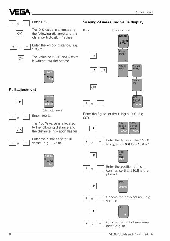
6 VEGAPULS 42 and 44 – 4 … 20 mA
Quick start
100.0%at
m (d)XX.XXX
OK
+ –or
+ –or
Enter 100 %.
The 100 % value is allocatedto the following distance andthe distance indication flashes.
Enter the distance with fullvessel, e.g. 1.27 m.
Condit-ioning
Scal-ing
0 %corresponds
XXXX
Adjust-ment
Para-meter
Sensor
m(d) 4.700
(Max. adjustment)
OK
OK
Enter the figure for the filling at 0 %, e.g.0001.
OK
+ –or
0 %corresponds
XXXX
100 %corresponds
XXXX
Deci-malpoint888.8
prop.toVolume
Unit
m3
+ –orEnter the figure of the 100 %filling, e.g. 2166 for 216.6 m3
Enter the position of thecomma, so that 216.6 is dis-played.
+ –or
Choose the physical unit, e.g.volume.
+ –or
Choose the unit of measure-ment, e.g. m3.
+ –or
OK
+ –or
OK
+ –or
Enter 0 %.
The 0 % value is allocated tothe following distance and thedistance indication flashes.
Enter the empty distance, e.g.5.85 m.
The value pair 0 % and 5.85 mis written into the sensor.
0.0%at
m (d)5,85
Full adjustment
Scaling of measured value display
Key Display text
100.0%at
m (d)1,27
VEGAPULS 42 and 44 – 4 … 20 mA 7
Product description
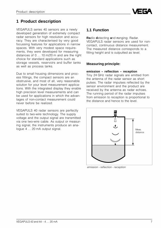
emission - reflection - reception
Meas.distance
1 Product description
VEGAPULS series 40 sensors are a newlydeveloped generation of extremely compactradar sensors for high resolution and accu-racy. They are characterised by very goodfocussing features for applications in narrowspaces. With very modest space require-ments, they were developed for measuringdistances of 0 … 10 m/20 m and are the rightchoice for standard applications such asstorage vessels, reservoirs and buffer tanksas well as process tanks.
Due to small housing dimensions and proc-ess fittings, the compact sensors are anobstrusive, and most of all, very reasonablesolution for your level measurement applica-tions. With the integrated display they enablehigh precision level measurements and canbe used for applications in which the advan-tages of non-contact measurement couldnever before be realized.
VEGAPULS 40 radar sensors are perfectlysuited to two-wire technology. The supplyvoltage and the output signal are transmittedvia one two-wire cable. As output or measur-ing signal, the instruments produce an ana-logue 4 … 20 mA output signal.
1.1 Function
Radio detecting and ranging: Radar.VEGAPULS radar sensors are used for non-contact, continuous distance measurement.The measured distance corresponds to afilling height and is outputted as level.
Measuring principle:
emission – reflection – receptionTiny 24 GHz radar signals are emitted fromthe antenna of the radar sensor as shortpulses. The radar impulses reflected by thesensor environment and the product arereceived by the antenna as radar echoes.The running period of the radar impulsesfrom emission to reception is proportional tothe distance and hence to the level.

8 VEGAPULS 42 and 44 – 4 … 20 mA
Reflected radar power dependent on the dielectricconstant of the measured product
20
0
10
25 %
40 %
5
10
5 %
20
30
40
50
%
4 6 8 12 14 16 1820 r
t t
1 ns
278 ns
Time transformation
Pulse sequence
Product description
The radar impulses are emitted by the an-tenna system as pulse packages with apulse duration of 1 ns and pulse intervals of278 ns; this corresponds to a pulse packagefrequency of 3.6 MHz. In the impulse inter-vals, the antenna system operates as re-ceiver. Signal running periods of less thanone billionth of a second must be processedand the echo image must be evaluated in afraction of a second.
All products which are electrically conductivereflect radar signals very well. Even slightlyconductive products ensure a sufficient re-flection for a reliable measurement.
All products with a dielectric constant r ofmore than 2.0 reflect radar impulses suffi-ciently (note: air has a dielectric constant r of1).
The signal reflection increases with the con-ductivity or with the dielectric constant of theproduct. Hence, virtually all products can bemeasured.
With standard flanges of DN 50 to DN 250,ANSI 2“ to ANSI 10“ or G 11/2 A and 11/2“ NPT,the sensor antenna systems can be adaptedto the various measured products and meas-urement environments.
The high-quality materials can also withstandextreme chemical and physical conditions.The sensors deliver a stable, reproducibleanalogue or digital level signal with reliabilityand precision, and have a long useful life.
VEGAPULS radar sensors can accomplishthis through a special time transformationprocedure which spreads out the more than3.6 million echo images per second in a slow-motion picture, then freezes and processesthem.
Hence, it is possible for the VEGAPULS 40radar sensors to process the slow-motionpictures of the sensor environment preciselyand in detail in cycles of 0.5 to 1 secondwithout using time-consuming frequencyanalysis (e.g. FMCW, required by other radartechniques).
Virtually all products can be measured
Radar signals display physical propertiessimilar to those of visible light. According tothe quantum theory, they propagate throughempty space. Hence, they are not depend-ent on a conductive medium (as e.g. soundwaves in air), and spread out like light at thespeed of light. Radar signals react to twobasic electrical properties:- the electrical conductivity of a substance- the dielectric constant of a substance.

VEGAPULS 42 and 44 – 4 … 20 mA 9
Product description
Temperature influence: Temperature error absolutelyzero (e.g. at 500°C 0.018 %)
Pressure influence: Error with pressure increase verylow (e.g. at 50 bar 1.44 %)
100 500 1000 1300 ˚C0
0
0,01
0,02
0,03
%
0,018 %0,023 %
100
0
5
%
1,44 %2,8 %
10
5020 30 40 60 10070 80 90 110 120 130 140 bar
0,29 %
3,89 %
Continuous and reliable
Unaffected by temperature, pressure andindividual gas atmospheres, VEGAPULSradar sensors are used for quick and reliablecontinuous level measurement of variousproducts.
VEGAPULS 40 sensors enable level meas-urement with radar in facilities where previ-ously, due to high cost, it was completely outof the question.
1.2 Application features
Applications• level measurement of liquids• measurement also in vacuum• all slightly conductive materials and all
substances with a dielectric constant > 2.0can be measured
• measuring range 0 … 10 m (type 42).measuring range 0 … 20 m (type 44).
Two-wire technology• supply and output signal on one two-wire
cable (Loop powered)• 4 … 20 mA output signal or HART® output
signal.
Rugged and abrasion proof• non-contact• high-resistance materials
Exact and reliable• accuracy 0.05 %.• resolution 1 mm.• unaffected by noise, vapours, dusts, gas
compositions and inert gas stratification• unaffected by varying density and tem-
perature of the medium• measurement in pressures up to 40 bar
and product temperatures up to 200°C
Communicative• integrated display of measured value• optional display module separate from
sensor• adjustment with detachable adjustment
module, pluggable in the sensor or in theexternal display
• adjustment from the PLC level with the PC• adjustment with HART® handheld
Approvals• CENELEC, ATEX, PTB, FM, CSA, ABS,
LRS, GL, LR, FCC.

10 VEGAPULS 42 and 44 – 4 … 20 mA
Visualised input of a vessel linearisation curve
The adjustment program recognises the sensor type
The PC can be connected at any location inthe system or on the signal cable. It is con-nected by means of the two-wire PC interfaceconverter VEGACONNECT 2 to the sensor orthe signal cable. The adjustment and param-eter data can be saved with the adjustmentsoftware on the PC and can be protected bypasswords. On request, the adjustments canbe quickly transferred to other sensors.
Product description
1.3 Adjustment
Each measuring situation is unique. For thatreason, every radar sensor needs somebasic information on the application and theenvironment, e.g. which level means "empty“and which level "full“. Beside this "empty andfull adjustment“, many other settings andadjustments are possible with VEGAPULSradar sensors.
The adjustment and parameter setting ofradar sensors are carried out with- the PC- the detachable adjustment module MINI-
COM- the HART®- handheld
Adjustment with PC
The setup and adjustment of the radar sen-sors is generally done on the PC with theadjustment program VEGA Visual Operating(VVO) under Windows®. The program leadsquickly through the adjustment and param-eter setting by means of pictures, graphicsand process visualisations.
Adjustment with the PC on the analogue 4 … 20 mAsignal and supply cable or directly on the sensor(four-wire sensor)
2
2 4 ... 20 mA
VEGAPULS 42 and 44 – 4 … 20 mA 11
Detachable adjustment module MINICOM
- + ESC
OK
Tank 1
m (d)12.345
2
2
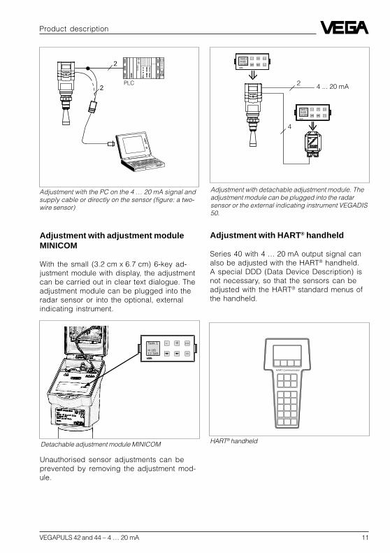
Adjustment with the PC on the 4 … 20 mA signal andsupply cable or directly on the sensor (figure: a two-wire sensor)
Product description
Adjustment with adjustment moduleMINICOM
With the small (3.2 cm x 6.7 cm) 6-key ad-justment module with display, the adjustmentcan be carried out in clear text dialogue. Theadjustment module can be plugged into theradar sensor or into the optional, externalindicating instrument.
PLC
Unauthorised sensor adjustments can beprevented by removing the adjustment mod-ule.
2
4
4 ... 20 mA
- + ESC
OK
Tank 1m (d)12.345
- + ESC
OK
Tank 1m (d)12.345
Adjustment with detachable adjustment module. Theadjustment module can be plugged into the radarsensor or the external indicating instrument VEGADIS50.
Adjustment with HART® handheld
Series 40 with 4 … 20 mA output signal canalso be adjusted with the HART® handheld.A special DDD (Data Device Description) isnot necessary, so that the sensors can beadjusted with the HART® standard menus ofthe handheld.
HART® handheld
HART Communicator

12 VEGAPULS 42 and 44 – 4 … 20 mA
1.4 Antennas
The antenna is the eye of the radar sensor.An uninitiated observer would probably notrealise how carefully the antenna geometrymust be adapted to the physical propertiesof electromagnetic fields.The geometrical form determines focal prop-erties and sensitivity - the same way it deter-mines the sensitivity of a unidirectionalmicrophone.
Four antenna systems are available for differ-ent applications and process requirements.
Horn antennas
Horn antennas focus theradar signals very well.Manufactured of 1.4435(stainless steel) or Hastel-loy C22, they are very rug-ged, and are physically aswell as chemically, resistant.They are suitable for pres-sures up to 40 bar and forproduct temperatures up to150°C. The horn diametersdetermine the focussing ofthe radar signals. The an-tenna gain grows strongerwith increasing diameter(40, 48, 75, 95 mm). Theantenna gain representsthe ratio of emitted energyto received echo energy.
Product description
2
24 ...20 mA
HART® handheld on the 4 … 20 mA signal cable
For adjustment, just connect the HART® hand-held to the 4 … 20 mA output signal cable orinsert the two communication cables of theHART® handheld into the adjustment jacks onthe sensor.
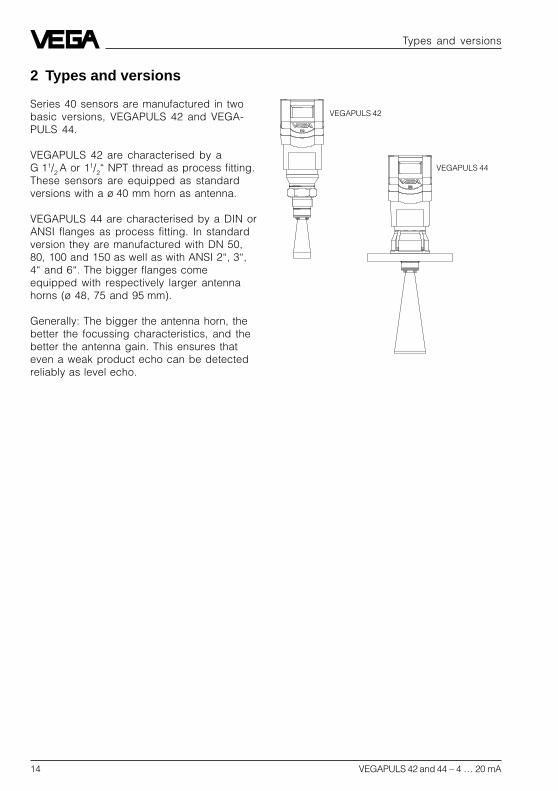
VEGAPULS 42
VEGAPULS 44

VEGAPULS 42 and 44 – 4 … 20 mA 13
Product description
Pipe antennas
The pipe antennas on surgeor bypass tubes only form acomplete antenna system inconjunction with a measuringtube (which can also becurved). The measuring tubeacts as a conductor forradar signals. The runningperiod of the radar signalschanges in the tube and isdependent on tube diameter.The tube inner diameter mustbe programmed in the sen-sor so that it can take thealtered running time intoaccount and deliver preciselevel signals. Pipe antennasare especially suitable forprocesses with intenseproduct movements or prod-ucts with low dielectric con-stant.
The antennas are character-ised by very high gain. Highreliability can be achievedeven with products with verypoor reflective features.
VEGAPULS 44 on bypass tube
VEGAPULS 42 on bypass tube
14 VEGAPULS 42 and 44 – 4 … 20 mA
Types and versions
2 Types and versions
Series 40 sensors are manufactured in twobasic versions, VEGAPULS 42 and VEGA-PULS 44.
VEGAPULS 42 are characterised by aG 11/2 A or 11/2“ NPT thread as process fitting.These sensors are equipped as standardversions with a ø 40 mm horn as antenna.
VEGAPULS 44 are characterised by a DIN orANSI flanges as process fitting. In standardversion they are manufactured with DN 50,80, 100 and 150 as well as with ANSI 2“, 3“,4“ and 6“. The bigger flanges comeequipped with respectively larger antennahorns (ø 48, 75 and 95 mm).
Generally: The bigger the antenna horn, thebetter the focussing characteristics, and thebetter the antenna gain. This ensures thateven a weak product echo can be detectedreliably as level echo.
VEGAPULS 42
VEGAPULS 44

VEGAPULS 42 and 44 – 4 … 20 mA 15
2.1 Survey
General features• Application preferably for liquids in storage tanks, reservoirs and process vessels with
increased accuracy requirements.• Measuring range 0 … 10 m or 0 … 20 m.• Ex approved in zone 1 (IEC) or zone 1 (ATEX) classification
EEx ia [ia] IIC T6.• Integrated display of measured values.
Survey
VEGAPULS …42 44
Signal output– active (4 … 20 mA) • •– passive (4 … 20 mA loop powered) • •
Voltage supply– two-wire technology (voltage
supply and signal outputvia one two-wire cable) • •
– four-wire technology (voltagesupply separate from the signalcable) • •
Process fitting– G 11/2 A; 11/2“ NPT • –– DN 50; ANSI 2“ – •– DN 80; ANSI 3“ – •– DN 100; ANSI 4“ – •– DN 150; ANSI 6“ – •
Adjustment– PC • •– adjustment module in the sensor • •– adjustment module in external
indicating instrument • •– HART® handheld • •
Measuring range max.– ø 40 mm horn 10 m –– ø 48 mm horn 15 m 15 m– ø 75 mm horn 20 m 20 m– ø 95 mm horn 20 m 20 m
Types and versions

16 VEGAPULS 42 and 44 – 4 … 20 mA
Type code
PS 42 .XX X X X XXX X XK - Plastic housing PBT, M20 x 1,5 cable entryN - Plastic housing PBT, 1/2“ NPT cable entryA - Aluminium housing, M20 x 1,5 cable entryD - Aluminium housing, 1/2“ NPT cable entry in Exd connection
housing
V - Seal of the antenna system: VitonA - Seal of the antenna system: Kalrez
G - Process fitting G 11/2 AN - Process fitting 11/2“ NPTABC- Process fitting DN 50 PN 16BBE- Process fitting DN 80 PN 16CBG-Process fitting DN 100 PN 16DBG-Process fitting DN 150 PN 16ARC- Process fitting ANSI 2“ 150 psiBRE- Process fitting ANSI 3“ 150 psiCRG-Process fitting ANSI 4“ 150 psiDRG-Process fitting ANSI 6“ 150 psiYYY- Process fitting on request
X - without displayA - with integrated display
X - without adjustment module MINICOMB - with adjustment module MINICOM (mounted)
B - 20 … 72 V DC; 20 … 250 V AC; 4 … 20 mA, HART®
(four-wire)D - Two-wire (loop powered), 4 … 20 mA, HART®
E - Supply via signal conditioning instrumentG - Segment coupler for Profibus PA
XX - FTZ (standard telecommunication approval Germany)AX - Approval in Ex-Zone 1, EEx ia IIC T6CX - Approval in Ex-Zone 0, EEx ia IIC T6BX - Approval in Ex-Zone 1 (Exd connection housing)DX - Approval in Ex-Zone 0 (Exd connection housing)
Type 42: with screw-on process fittingType 44: instrument series with flange process fitting
PS: Series 40 radar sensors
Types and versions

VEGAPULS 42 and 44 – 4 … 20 mA 17
2 4 … 20 mA
-+1)
4
2.2 Configuration of measuringsystems
A measuring system consists of a sensorwith a 4 … 20 mA signal output and a modulethat evaluates and further processes thelevel-proportional current signal.
On the following pages you will see variousmeasuring systems, each consisting of adifferent instrument configuration (severalalso with signal conditioning).
Measuring systems in two-wire technol-ogy:• 4 … 20 mA shown without processing unit,
(bottom)• 4 … 20 mA on active PLC, (page 18)• 4 … 20 mA in Ex area on active PLC (Ex ia
page 20, Ex d PAGE 23)• 4 … 20 mA in Ex area on passive PLC,
(page 21)• 4 … 20 mA in Ex area on VEGADIS 371 Ex
indicating instrument, (page 22)
Measuring systems in four-wire technol-ogy:• 4 … 20 mA shown without signal condi-
tioning instrument, (non Ex page 19, Ex dpage 23)
VEGADIS 50
VEGA-CONNECT 2
HART® handheld
Types and versions
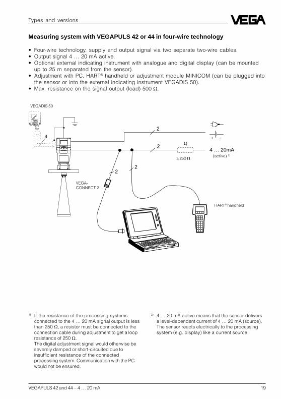
Measuring systems with VEGAPULS 42 or 44 connected to any 4 … 20 mA signalprocessing unit
• Two-wire technology (loop powered), supply and output signal via one two-wire cable.• Output signal 4 … 20 mA (passive).• Optional external indicating instrument with analogue and digital display (can be mounted
up to 25 m separated from the sensor).• Adjustment with PC, HART® handheld or the adjustment module MINICOM (can be plugged
into the sensor or into the external indicating instrument VEGADIS 50).
1) If the resistance of the processing systemsconnected to the 4 … 20 mA signal output is lessthan 250 , a resistor must be connected to theconnection cable during adjustment to get a loopresistance of 250 .The digital adjustment signal would otherwise beseverely damped or short-circuited due toinsufficient resistance of the connectedprocessing system. Communication with the PCwould not be ensured.

18 VEGAPULS 42 and 44 – 4 … 20 mA
2 2 4 … 20 mA
4
2 2
Measuring system with VEGAPULS 42 or 44 on active PLC
• Two-wire technology, supply by active PLC.• Output signal 4 … 20 mA (passive).• Measured value display integrated in the sensor.• Optional external indicating instrument (can be mounted up to 25 m separated from the
sensor in Ex area).• Adjustment with PC, HART® handheld or the adjustment module MINICOM (can be plugged
into the sensor or into the external indication instrument).
HART® handheld
VEGA-CONNECT 2
Types and versions
1) If the resistance of the processing systemsconnected to the 4 … 20 mA signal output is lessthan 250 , a resistor must be connected to theconnection cable during adjustment to get a loopresistance of 250 .The digital adjustment signal would otherwise beseverely damped or short-circuited due toinsufficient resistance of the connected processingsystem. Communication with the PC would not beensured.
1 )
VEGADIS 50
passive 2)
PLC (active) 3)
2) 4 … 20 mA passive means that the sensorconsumes a level-dependent current of4 … 20 mA. The sensor reacts electrically like avarying resistor (consumer) to the PLC.
3) Active means that the PLC powers the passivesensor as voltage source.
VEGAPULS 42 and 44 – 4 … 20 mA 19
Types and versions
2
-+
4 … 20mA2
22
1)
4
Measuring system with VEGAPULS 42 or 44 in four-wire technology
• Four-wire technology, supply and output signal via two separate two-wire cables.• Output signal 4 … 20 mA active.• Optional external indicating instrument with analogue and digital display (can be mounted
up to 25 m separated from the sensor).• Adjustment with PC, HART® handheld or adjustment module MINICOM (can be plugged into
the sensor or into the external indicating instrument VEGADIS 50).• Max. resistance on the signal output (load) 500
(active) 2)
VEGADIS 50
1) If the resistance of the processing systemsconnected to the 4 … 20 mA signal output is lessthan 250 , a resistor must be connected to theconnection cable during adjustment to get a loopresistance of 250 .The digital adjustment signal would otherwise beseverely damped or short-circuited due toinsufficient resistance of the connectedprocessing system. Communication with the PCwould not be ensured.
HART® handheld
VEGA-CONNECT 2
250
2) 4 … 20 mA active means that the sensor deliversa level-dependent current of 4 … 20 mA (source).The sensor reacts electrically to the processingsystem (e.g. display) like a current source.
20 VEGAPULS 42 and 44 – 4 … 20 mA
2 4 … 20 mA
2
22
4
Types and versions
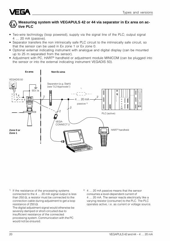
Measuring system with VEGAPULS 42 or 44 via separator in Ex area on ac-tive PLC
• Two-wire technology (loop powered), supply via the signal line of the PLC; output signal4 … 20 mA (passive).
• Separator transfers the non intrinsically safe PLC circuit to the intrinsically safe circuit, sothat the sensor can be used in Ex zone 1 or Ex zone 0.
• Optional external indicating instrument with analogue and digital display (can be mountedup to 25 m separated from the sensor).
• Adjustment with PC, HART® handheld or adjustment module MINICOM (can be plugged intothe sensor or into the external indicating instrument VEGADIS 50).
HART® handheld
Ex area Non Ex area
Separator (e.g. Stahl)(see "3.2 Approvals“)
VEGA-CONNECT 2
VEGADIS 50
passive 2)
1 )
PLC (active)
1) If the resistance of the processing systemsconnected to the 4 … 20 mA signal output is lessthan 250 , a resistor must be connected to theconnection cable during adjustment to get a loopresistance of 250 .The digital adjustment signal would otherwise beseverely damped or short-circuited due toinsufficient resistance of the connectedprocessing system. Communication with the PCwould not be ensured.
Zone 0 orZone 1
EEx ia
2) 4 … 20 mA passive means that the sensorconsumes a level-dependent current of4 … 20 mA. The sensor reacts electrically like avarying resistor (consumer) to the PLC. The PLCoperates active, i.e. as current or voltage source.

VEGAPULS 42 and 44 – 4 … 20 mA 21
2 4 … 20 mA
22
4
-+
Measuring system with VEGAPULS 42 or 44 via separator (Smart-Transmit-ter) on passive PLC
• Two-wire technology (loop powered), intrinsically safe ia supply via the signal cable of theseparator for operation of the sensor in Ex zone 1 or Ex zone 0.
• Output signal sensor 4 … 20 mA passive.Output signal separator 4 … 20 mA active.
• Optional external indicating instrument with analogue and digital display (can be mountedup to 25 m separated from the sensor).
• Adjustment with PC, HART® handheld or adjustment module MINICOM (can be plugged intothe sensor or into the external indicating instrument VEGADIS 50).
Types and versions
(active) 2)
VEGA-CONNECT 2
Separator (e.g. VEGATRENN 149 Ex see"3.2 Approvals“)
VEGADIS 50
1 )
PLC (passive) 3)
Ex area Non Ex area
1) If the resistance of the processing systemsconnected to the 4 … 20 mA signal output is lessthan 250 , a resistor must be connected to theconnection cable during adjustment to get a loopresistance of 250 .The digital adjustment signal would otherwise beseverely damped or short-circuited due toinsufficient resistance of the connectedprocessing system. Communication with the PCwould not be ensured.
2) 4 … 20 mA active means that the separatordelivers a level-dependent current of 4 … 20 mA(source). The separator reacts electrically to thePLC like a current source.
3) 4 … 20 mA passive means that the PLC consumesa level-dependent current of 4 … 20 mA. The PLCreacts electrically like a varying resistor(consumer) to the PLC.
HART® handheld
Zone 0 orZone 1
EEx ia

22 VEGAPULS 42 and 44 – 4 … 20 mA
Types and versions
22
4 2
-+
4 ... 20 mA
VEGADIS 371 Ex
Measuring system with VEGAPULS 42 or 44 on VEGADIS 371 Ex indicatinginstrument with current and relay output
• Two-wire technology (loop powered), intrinsically safe ia supply via the signal cable of theVEGADIS 371 Ex indicating instrument for operation of the sensor in Ex zone 1 or Exzone 0.
• Optional external indicating instrument with analogue and digital display (can be mountedup to 25 m separated from the sensor).
• Adjustment with PC, HART® handheld or adjustment module MINICOM (can be plugged intothe sensor or into the external indicating instrument VEGADIS 50).
(passive)
VEGADIS 50
0/4 … 20 mA(active)
Relay
(see "3.2 Approvals“)
Ex area Non Ex area
HART® handheld
VEGA-CONNECT 2
1) If the resistance of the processing systemsconnected to the 4 … 20 mA signal output is lessthan 250 , a resistor must be connected to theconnection cable during adjustment to get a loopresistance of 250 .The digital adjustment signal would otherwise beseverely damped or short-circuited due toinsufficient resistance of the connectedprocessing system. Communication with the PCwould not be ensured.
1 )
Zone 0 orZone 1
EEx ia

VEGAPULS 42 and 44 – 4 … 20 mA 23
Types and versions
VEGAPULS 42 Ex or 44 Ex (loop powered) with pressure-tight encapsulatedterminal compartment on active PLC
• Two-wire technology, supply via the signal cable of active PLC on Exd connection housingfor operation in Ex zone 1 (VEGAPULS …Ex) or Ex zone 0 (VEGAPULS …Ex0).
• Output signal 4 … 20 mA (passive).• Measured value display integrated in the sensor.• Optional external indicating instrument (can be mounted up to 25 m separated from the
sensor in Ex area).• Adjustment with PC, HART® handheld or adjustment module MINICOM (can be plugged into
the sensor or into the external indicating instrument VEGADIS 50).
1) If the resistance of the processing systemsconnected to the 4 … 20 mA signal output is lessthan 250 , a resistor must be connected to theconnection cable during adjustment to get a loopresistance of 250 .The digital adjustment signal would otherwise beseverely damped or short-circuited due toinsufficient resistance of the connectedprocessing system. Communication with the PC orthe HART® handheld would not be ensured.
2 4 … 20 mA
22
4 2
VEGA-CONNECT 2
VEGADIS 50 Ex
passive 2)
Ex area Non Ex-area
HART® hand-held
PLC (active)
2) 4 … 20 mA passive means that the sensorconsumes a level-dependent current of4 … 20 mA. The sensor reacts electrically like avarying resistor (consumer) to the PLC.
24 VEGAPULS 42 and 44 – 4 … 20 mA
Technical data
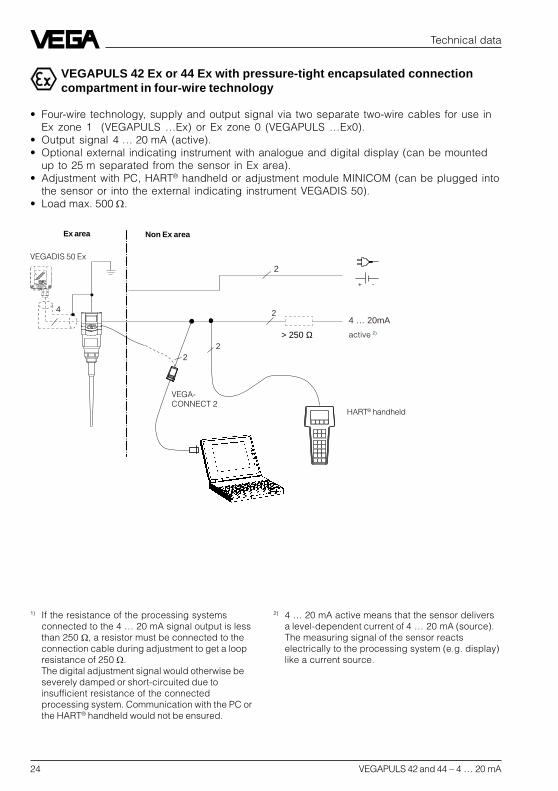
VEGAPULS 42 Ex or 44 Ex with pressure-tight encapsulated connectioncompartment in four-wire technology
• Four-wire technology, supply and output signal via two separate two-wire cables for use inEx zone 1 (VEGAPULS …Ex) or Ex zone 0 (VEGAPULS …Ex0).
• Output signal 4 … 20 mA (active).• Optional external indicating instrument with analogue and digital display (can be mounted
up to 25 m separated from the sensor in Ex area).• Adjustment with PC, HART® handheld or adjustment module MINICOM (can be plugged into
the sensor or into the external indicating instrument VEGADIS 50).• Load max. 500.
22
4 2
2
-+
4 … 20mA
> 250 Ω
1) If the resistance of the processing systemsconnected to the 4 … 20 mA signal output is lessthan 250 , a resistor must be connected to theconnection cable during adjustment to get a loopresistance of 250 .The digital adjustment signal would otherwise beseverely damped or short-circuited due toinsufficient resistance of the connectedprocessing system. Communication with the PC orthe HART® handheld would not be ensured.
VEGA-CONNECT 2
VEGADIS 50 Ex
Ex area
active 2)
HART® handheld
Non Ex area
2) 4 … 20 mA active means that the sensor deliversa level-dependent current of 4 … 20 mA (source).The measuring signal of the sensor reactselectrically to the processing system (e.g. display)like a current source.

VEGAPULS 42 and 44 – 4 … 20 mA 25
1000
900
800
700670
600
500
400
300
250
200
100
0
14 20 25 30 35
15 29 36
V
Ω
975
720
25,519,5
Adjustmentresistor(HART® andVEGACON-NECT)
max. voltage limitEx ia sensors
max. voltage limitNon Ex andEx d ia sensors
min. voltage limit when using the HART®
adjustment resistor:- Non Ex and Ex ia sensors- Ex d ia sensors
Non Ex and Ex i
a
Exd ia
3 Technical data
3.1 Technical data
Power supply
Supply voltage- four-wire sensor 24 V DC (20 … 72 V DC)
230 V AC (20 … 250 V AC), 50/60 Hzfuse 0.2 A TR
- two-wire sensor 24 V DC (14 … 36 V DC)- two-wire Ex ia sensor 24 V DC (14 … 29 V DC)- two-wire Ex d ia sensor 24 V DC (20 … 36 V DC)
Current consumption- four-wire sensor max. 60 mA- two-wire sensor max. 22.5 mAPower consumption- four-wire sensor max. 200 mW, 1.2 VA- two-wire sensor 55 … 810 mWLoad- four-wire sensor max. 500 Ohm- two-wire sensor see diagram
Technical data
max. load Non Ex
max. load Ex d ia
max. load Ex ia
26 VEGAPULS 42 and 44 – 4 … 20 mA
Technical data
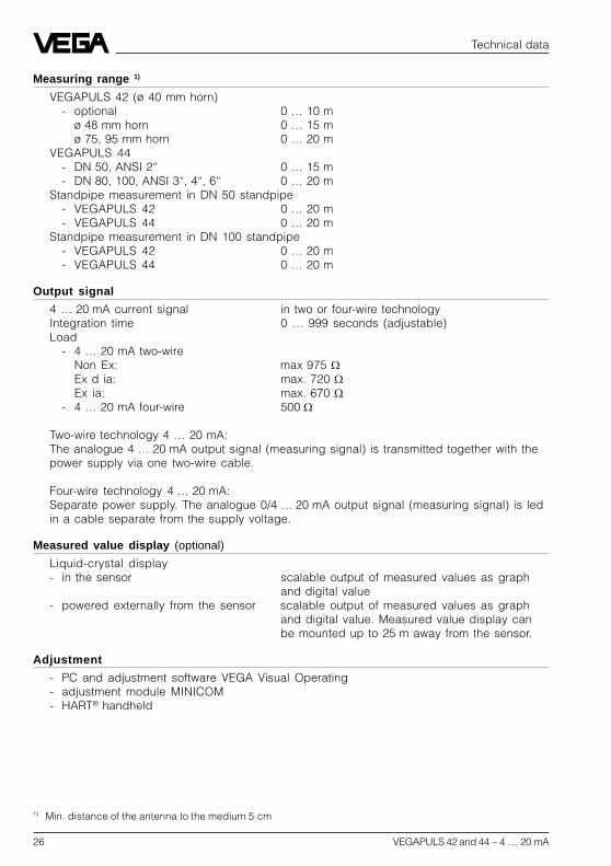
Measuring range 1)
VEGAPULS 42 (ø 40 mm horn)- optional 0 … 10 m
ø 48 mm horn 0 … 15 mø 75, 95 mm horn 0 … 20 m
VEGAPULS 44- DN 50, ANSI 2“ 0 … 15 m- DN 80, 100, ANSI 3“, 4“, 6“ 0 … 20 m
Standpipe measurement in DN 50 standpipe- VEGAPULS 42 0 … 20 m- VEGAPULS 44 0 … 20 m
Standpipe measurement in DN 100 standpipe- VEGAPULS 42 0 … 20 m- VEGAPULS 44 0 … 20 m
Output signal
4 … 20 mA current signal in two or four-wire technologyIntegration time 0 … 999 seconds (adjustable)Load
- 4 … 20 mA two-wireNon Ex: max 975 Ex d ia: max. 720 Ex ia: max. 670
- 4 … 20 mA four-wire 500
Two-wire technology 4 … 20 mA:The analogue 4 … 20 mA output signal (measuring signal) is transmitted together with thepower supply via one two-wire cable.
Four-wire technology 4 … 20 mA:Separate power supply. The analogue 0/4 … 20 mA output signal (measuring signal) is ledin a cable separate from the supply voltage.
Measured value display (optional)
Liquid-crystal display- in the sensor scalable output of measured values as graph
and digital value- powered externally from the sensor scalable output of measured values as graph
and digital value. Measured value display canbe mounted up to 25 m away from the sensor.
Adjustment
- PC and adjustment software VEGA Visual Operating- adjustment module MINICOM- HART® handheld
1) Min. distance of the antenna to the medium 5 cm

VEGAPULS 42 and 44 – 4 … 20 mA 27
Technical data
Accuracy 2)
(typical values under reference conditions, all statements relate to the nominal measuringrange)
Characteristics linearDeviation in characteristics including
linearity, reproducibility andhysteresis (determined acc. to thelimit point method) < 0.05 %
Linearity better than 0.05 %Average temperature coefficient of thezero signal 0.06 %/10 KResolution in general max. 1 mmResolution of the output signal 0.01 % or 1 mm
Characteristics 1)
(typical values under reference conditions, all statements relate to the nominal measuringrange)
Min. span betweenfull and empty > 10 mm (recommended > 50 mm)
Frequency 24 GHz technologyIntervals- two-wire sensor (4 … 20 mA) 1 s- two-wire sensor (digital) 0.6 s- four-wire sensor 0.5 sBeam angle (at –3 dB)
- VEGAPULS 42 22°optional 18°, 10° and 8° when using bigger coupling
horn deviating from nominal size- VEGAPULS 44
DN 50, ANSI 2“ 18°DN 80, ANSI 3“ 10°DN 100, ANSI 4“ 8°DN 150, ANSI 6“ 8°
Adjustment time (response time) > 1 s (depending on parameter setting)Influence of the process temperature not measurable at 0 bar; at 5 bar 0.004 %/10 K;
at 40 bar 0.03 %/10 KInfluence of the process pressure 0.0265 %/barAdjustment time 2) > 1 s (depending on parameter setting)Radar emitted power (average) 0.717 µWReceived average emitted power 3)
- distance 1 m 0.5 … 1.5 nW pro cm² (0.5 … 1.5 x 10⁻⁹W/cm²)- distance 5 m 0.02 … 0.6 nW pro cm²
1) Similar to DIN 16 086, reference conditions acc. to IEC 770, e.g.temperature 15°C … 35°C; moisture 45 % … 75 %; pressure 860 mbar … 1060 mbar
2) The adjustment time (also actuating time, response time or adjustment period) is the time the sensorrequires to output the correct level (with max. 10% deviation) after a quick level change.
3) Average emitted power reaching an object (electromagnetic energy) per cm² directly in front of the antenna.The received emitted power depends on the antenna version and the distance.
28 VEGAPULS 42 and 44 – 4 … 20 mA
Technical data
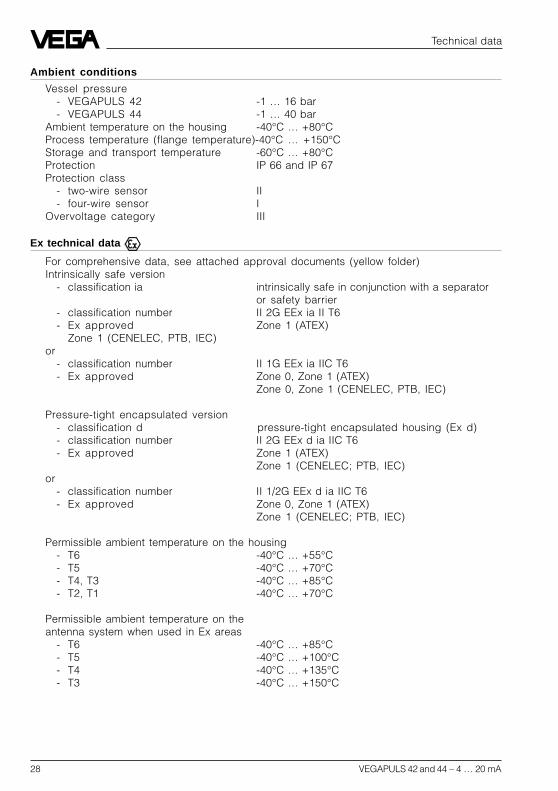
Ambient conditions
Vessel pressure- VEGAPULS 42 -1 … 16 bar- VEGAPULS 44 -1 … 40 bar
Ambient temperature on the housing -40°C … +80°CProcess temperature (flange temperature)-40°C … +150°CStorage and transport temperature -60°C … +80°CProtection IP 66 and IP 67Protection class
- two-wire sensor II- four-wire sensor I
Overvoltage category III
Ex technical data
For comprehensive data, see attached approval documents (yellow folder)Intrinsically safe version
- classification ia intrinsically safe in conjunction with a separatoror safety barrier
- classification number II 2G EEx ia II T6- Ex approved Zone 1 (ATEX)
Zone 1 (CENELEC, PTB, IEC)or
- classification number II 1G EEx ia IIC T6- Ex approved Zone 0, Zone 1 (ATEX)
Zone 0, Zone 1 (CENELEC, PTB, IEC)
Pressure-tight encapsulated version- classification d pressure-tight encapsulated housing (Ex d)- classification number II 2G EEx d ia IIC T6- Ex approved Zone 1 (ATEX)
Zone 1 (CENELEC; PTB, IEC)or
- classification number II 1/2G EEx d ia IIC T6- Ex approved Zone 0, Zone 1 (ATEX)
Zone 1 (CENELEC; PTB, IEC)
Permissible ambient temperature on the housing- T6 -40°C … +55°C- T5 -40°C … +70°C- T4, T3 -40°C … +85°C- T2, T1 -40°C … +70°C
Permissible ambient temperature on theantenna system when used in Ex areas
- T6 -40°C … +85°C- T5 -40°C … +100°C- T4 -40°C … +135°C- T3 -40°C … +150°C

VEGAPULS 42 and 44 – 4 … 20 mA 29
Process fittings
VEGAPULS 42 G 11/2 A, 11/2“ NPT screw-on antennawith ø 40 mm antenna horn (antenna hornsof ø 48 … 95 mm can be retrofitted as option)
VEGAPULS 44 DN 50, DN 80, DN 100, DN 150, ANSI 2“, 3“, 4“and 6“ (horn antenna)
Connection cable
Two-wire sensors supply and signal via onetwo-wire cable
Four-wire sensor supply and signal separateCross-section area of conductor generally 2.5 mm2
Ground connection max. 4 mm2
Cable entry- ia terminal compartment 2 x M20 x 1.5 (cable diameter 5 … 9 mm)- Exd terminal compartment 2 x 1/2“ NPT EEx d (cable diameter
3.1 … 8.7 mm or 0.12 … 0.34 inch)
Materials
Housing PBT (Valox) oraluminium die-casting (GD-AlSi 10 Mg)
EEx d connection compartment aluminium ingot casting (GK-AlSi 7 Mg)Process fitting 1.4435Antenna (wetted parts) 1.4435 and PTFEAntenna seal with
horn and pipe antenna- standard Viton- option Kalrez, Viton for low temperature
Weights
VEGAPULS 42 1.5 … 3.6 kgVEGAPULS 44
- DN 50 5.8 … 6.5 kg- DN 80 7.6 … 8.4 kg- DN 100 8.6 … 9.4 kg- DN 150 13.5 … 14.2 kg- ANSI 2“ 5.2 … 5.7 kg- ANSI 3“ 6.9 … 7.5 kg- ANSI 4“ 10.5 … 11.1 kg- ANSI 6“ 14.6 … 15.4 kg
CE conformity
VEGAPULS 42/44 radar sensors meet the protective regulations of EMC (89/336/EWG)and NSR (73/23/EWG). The conformity has been judged acc. to the following standards:EMC Emission EN 50 081 - 1: 1992; EN 50 041: 1997
Susceptibility EN 50 082 - 2: 1995; EN 50 020: 1994NSR EN 61 010 - 1: 1993
Technical data

30 VEGAPULS 42 and 44 – 4 … 20 mA
3.2 Approvals
When using radar sensors in Ex areas or onships, the instruments must be suitable andapproved for the explosion zones and appli-cations.The suitability is checked by the approvalauthorities and is certified in approval docu-ments.
Please note the attached approval docu-ments when using a sensor in Ex area.
Test and approval authorities
VEGAPULS radar sensors are tested andapproved by the following monitoring, testand approval authorities:
- PTB(Physikalisch Technische Bundesanstalt -Physical Technical Approval Authority)
- FM(Factory Mutual Research)
- ABS(American Bureau of Shipping)
- LRS(Lloyds Register of Shipping)
- GL(German Lloyd)
- CSA(Canadian Standards Association)
Technical data
Intrinsically safe in Ex environment
Series 40 sensors in EEx ia (intrinsically safe)version require for use in Ex areas specialseparators or safety barriers. The separatorsor safety barriers provide intrinsically safe(ia) circuits. Below, a selection of instrumentswith which series 40 sensors work reliably.
Separator and signal conditioning instru-ment:- VEGADIS 371 Ex- A puissance 3 PROFSI 37-24070A- VEGAMET 614 Ex- Apparatebau Hundsbach
AH MS 271-B41EEC 010
Separator:- VEGATRENN 149 Ex…- Stahl 9303/15/22/11- CEAG GHG 124 3111 C1206
Safety barrier:- Stahl 9001/01/280/110/10- CEAG GHG 11 1 9140 V0728- Typ 9130 (VEGA)- Stahl 9001/51/280/110/14- MTL 787 S+- CEAG CS 3/420-106
Pressure-tight encapsulated in Ex area
Series 42/44 sensors in EEx d ia (pressure-tight encapsulated) version can be used inEx areas without special safety barriers, dueto their pressure-tight encapsulated terminalcompartment (provided the appropriateinstallation regulations are observed).
VEGAPULS 42 and 44 – 4 … 20 mA 31
Technical data
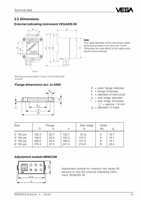
Flange dimensions acc. to ANSID = outer flange diameterb = flange thicknessk = diameter of hole circled1 = seal ledge diameterf = seal ledge thickness
1/16" = approx. 1.6 mmd2 = diameter of holes
External indicating instrument VEGADIS 50
82
Pg 13,5
118
108
135
38
85
ø5
10
48
Mounting on carrier rail 35 x 7.5 acc. to EN 50 022 or flatscrewed
f
d
b
d
kD
2
1
Note:The cable diameter of the connection cableshould be at least 5 mm and max. 9 mm.Otherwise the seal effect of the cable entrywould not be ensured.
Size Flange Seal ledge HolesD b k d1 No. d2
2" 150 psi 152.4 20.7 120.7 91.9 4 19.13" 150 psi 190.5 25.5 152.4 127.0 4 19.14" 150 psi 228.6 25.5 190.5 157.2 8 19.16" 150 psi 279.4 27.0 241.3 215.9 8 22.4
3.3 Dimensions
Adjustment module MINICOM
- + ESC
OK
Tank 1
m (d)12.345
74
32,5
67,5
Adjustment module for insertion into series 50sensors or into the external indicating instru-ment VEGADIS 50
32 VEGAPULS 42 and 44 – 4 … 20 mA
Technical data
215
185
370
205
185
215
370
205
11625
11625
M20x1,5
½" NPT
201
10˚ 101
91
182
322
M20x1,5
165
ø 40
100
22
145 19
9
ø 40
253
ø 40
307
ø125
ø18
ø165
1918
139
ø 48
ø 40
PBT: 53Al: 78
ø 160
ø18
ø 200
45˚
20
ø 75
219
DN 50 PN 16 DN 80 PN 16
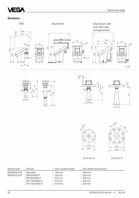
Sensor type Version max. socket length with antenna extension
VEGAPULS 42 Standard 140 mm 250 mmVEGAPULS 44 DN50/ANSI 2“ 135 mm 245 mm
DN 80/ANSI 3“ 210 mm 325 mmDN 100/ANSI 4“ 310 mm 425 mmDN 150/ANSI 6“ 310 mm 425 mm
PBT Aluminium Aluminium withExd terminalcompartment
Sensors

VEGAPULS 42 and 44 – 4 … 20 mA 33
Technical data
ø 180
ø 220
45˚
ø18
2031
9
ø 95
ø 240
ø22
ø 285
45˚
ø 95
319
22
DN 100 PN 16 DN 150 PN 16
ø 40 108
34 VEGAPULS 42 and 44 – 4 … 20 mA
Mounting and installation
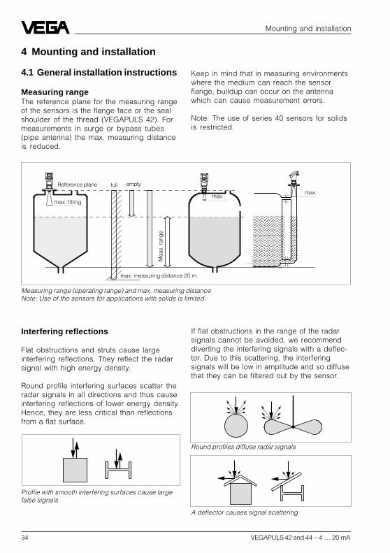
Measuring range (operating range) and max. measuring distanceNote: Use of the sensors for applications with solids is limited.
full
Mea
s. ra
nge
max. measuring distance 20 m
4 Mounting and installation
4.1 General installation instructions
Measuring rangeThe reference plane for the measuring rangeof the sensors is the flange face or the sealshoulder of the thread (VEGAPULS 42). Formeasurements in surge or bypass tubes(pipe antenna) the max. measuring distanceis reduced.
Keep in mind that in measuring environmentswhere the medium can reach the sensorflange, buildup can occur on the antennawhich can cause measurement errors.
Note: The use of series 40 sensors for solidsis restricted.
Reference plane empty
Profile with smooth interfering surfaces cause largefalse signals
Round profiles diffuse radar signals
A deflector causes signal scattering
max.max.
max. filling
Interfering reflections
Flat obstructions and struts cause largeinterfering reflections. They reflect the radarsignal with high energy density.
Round profile interfering surfaces scatter theradar signals in all directions and thus causeinterfering reflections of lower energy density.Hence, they are less critical than reflectionsfrom a flat surface.
If flat obstructions in the range of the radarsignals cannot be avoided, we recommenddiverting the interfering signals with a deflec-tor. Due to this scattering, the interferingsignals will be low in amplitude and so diffusethat they can be filtered out by the sensor.

VEGAPULS 42 and 44 – 4 … 20 mA 35
15 m
0 m
4,0 2,3 4,02,30
50%
m
25˚
18˚
100%
Emission cone of a VEGAPULS 42 with screw-onantenna and with ø 40 mm horn
10 m
0 m
3,50 1,90 3,501,900
50%
m
30˚
22˚
100%
Meas.distance
Emission cone of a DN 50 flange antenna
Meas.distance
Mounting and installation
VEGAPULS 44 withø 48 mm horn
Emission cone and interfering reflec-tions
The radar signals are focused by the an-tenna system. The signals leave the antennain a conical path similar to the beam patternof a spotlight. The form and intensity of theemission cone depend on the antenna used.
Any object in this beam cone causes a reflec-tion of the radar signals. Within the first fewmeters of the beam cone, tubes, struts orother installations can interfere with the meas-urement. At a distance of 6 m, the false echoof a strut has an amplitude nine times greaterthan at a distance of 18 m.
At greater distances, the energy of the radarsignal distributes itself over a larger area,thus causing weaker echoes from obstruct-ing surfaces. The interfering signals aretherefore less critical than those at closerange.
If possible, orient the sensor axis perpen-dicularly to the product surface and avoidvessel installations (e.g. pipes and struts)within the 100 % area of the emission cone.
The following illustrations of the emissionbeams are simplified and represent only themain beam - a number of weaker beams alsoexist. Therefore in practical application, theantenna has to be oriented so that the lowestpossible false echo signal strength isachieved. Only giving attention to a largeuseful echo is not always adequate underdifficult measuring conditions.
In a difficult measurement environment,searching for a mounting location with thelowest possible false echo intensity will bringthe best results. In most cases, the usefulecho will then be present with sufficientstrength. With the adjustment software VVOon the PC, you can have a look at the echoimage and optimise the mounting location(see chapter "6.2 Adjustment with the PC –Sensor optimisation – Echo curve“).
If possible, provide a "clear view“ to theproduct inside the emission cone and avoidvessel installations in the first third of theemission cone.
Optimum measuring conditions exist whenthe emission cone reaches the measuredproduct perpendicularly and when the emis-sion cone is free of obstructions.
VEGAPULS 42

36 VEGAPULS 42 and 44 – 4 … 20 mA
< 135 mm (DN 50)< 210 mm (DN 80)< 310 mm (DN 100, DN 150)
< 135 … 310 mm(250 … 425 mm)
Emission cone of a DN 80 flange antenna
Meas. distance
Mounting and installation
20˚
10˚
20 m
0 m
3,0 1,7 3,01,70m
100%
50%
Mounting on DIN socket piece
When mounting on dished vessel tops, theantenna length should at least correspond tothe length of the longer sockets.
Mounting on a dished vessel top; max. socket lengthdepending on flange size and, if applicable, on thelength of the antenna extension (see "3.3 Dimen-sions“).
4.2 Measurement of liquids
Horn antenna
Horn antenna on DIN socket pieceIn most cases, the mounting of radar sensorsis done on short DIN socket pieces. Thelower side of the instrument flange is thereference plane for the measuring range. Theantenna should always protrude out of theflange pipe.When the DIN socket piece is longer, pleasemake sure that the horn antenna is not cov-ered completely by the socket. It is better ifthe antenna protrudes slightly out of thesocket.
Reference plane
20 m
0 m
2,5 1,3 2,51,30
50%
m
14˚
8˚
100%
Emission cone of a DN 100 and DN 150 flange antenna
VEGAPULS 44 withø 75 mm horn
Meas. distance
VEGAPULS 44 withø 95 mm horn
Vessel center orsymmetry axis

VEGAPULS 42 and 44 – 4 … 20 mA 37
Mounting and installation
Mounting directly on the flat vessel top
Reference plane
Mounting on dished tank ends
Reference plane
1/2 vessel radius
Horn antenna directly on the vessel topIf the stability of the vessel will allow it (sensorweight), flat mounting directly on the vesseltop is a good and economical solution. Thetop side of the vessel is the reference plane.
Screw-on antenna with antenna extension on socketpiece
250 mm
Screw-on antenna
Screw-on antenna on socket pieceThe screwed antenna is mainly used on smallvessels. The antenna fits on small vesselopenings down to 11/2“ socket.
The socket must not be longer than 140 mm(when using the longer antenna, not longerthan 250 mm).
On dished tank ends, please do not mountthe instrument in the centre or close to thevessel wall, but approx. 1/2 vessel radius fromthe centre or from the vessel wall.
Dished tank ends can act as paraboloidalreflectors. If the radar sensor is placed in thefocal point of the parabolic tank, the radarsensor receives amplified false echoes. Theradar sensor should be mounted outside thefocal point. Parabolically amplified echoescan be thereby avoided.
Screw-on antenna on socket piece 11/2“
140 m
Reference plane
Vessel center orsymmetry axis

38 VEGAPULS 42 and 44 – 4 … 20 mA
Mounting and installation
Pipe antenna systems in the tank
Type label
Vent holeø 5 … 10 mm
Surge pipe weldedto the tank
Surge pipe in thesocket piece
Surge pipes which are open at the bottommust extend over the full measuring range(i.e. down to 0% level), as measurement isonly possible within the tube.
4.3 Measurement in standpipe(surge or bypass tube)
General instructions
Pipe antennas are preferred in vessels whichcontain many installations, e.g. heating tubes,heat exchangers or fast-running stirrers.Measurement is then possible where theproduct surface is very turbulent, and vesselinstallations cannot cause false echoes.
Due to concentration of the radar signal withinthe measuring tube, even products with smalldielectric constants (r= 1.6 up to 3) can bereliably measured in surge or bypass tubes.Please note the following instructions.
without deflector with deflector
min.
max.
Screw-on antenna directly in vessel opening
Screw-on antenna directly in vesselopening
As an alternative to socket mounting, thescrew-on antenna can be mounted in roundvessel openings (holes).

VEGAPULS 42 and 44 – 4 … 20 mA 39
100 %
0 %
> 300 mm
Mounting and installation
Tube flange system as bypass tube
Extended bypass tube on a vessel with turbulentproduct movements
Type label
75 %
0 %
100 %
> 300 mm
Make sure the required upper vent hole inthe surge pipe is aligned with the sensortype label.
As an alternative to a surge pipe in the ves-sel, a pipe antenna system outside the ves-sel in a bypass tube is also possible.The surge and bypass tubes must generallybe made of metal. For plastic tubes, aclosed, conductive jacket is always required.For metal tubes with plastic inner coating,make sure that the thickness of the coating isminimal (approx. 2 … 4 mm).
Align the sensor such that the type label lieson one axis with the tube holes or the tubeconnection openings. The polarisation of theradar signal enables a considerably stablermeasurement with this alignment.
When mounting the sensor on a bypass tube(e.g. on a previous floating or displacer unit),the radar sensor should be placed approx.300 mm or more from the max. level.
100 %
0 %
> 300 mm
300 ... 800 mm
Tube flange system as bypass tube
Type label
For products with small dielectric constants(< 4), a much longer bypass tube should beused than required by the lower tube con-nection. Products with small dielectric con-stants are partly penetrated by the radarsignals, so that the tube bottom delivers astronger echo than the product (when thebypass tube is nearly empty). Due to theextension of the lower tube end, sufficientliquid will remain even when the vessel isemptied.
40 VEGAPULS 42 and 44 – 4 … 20 mA
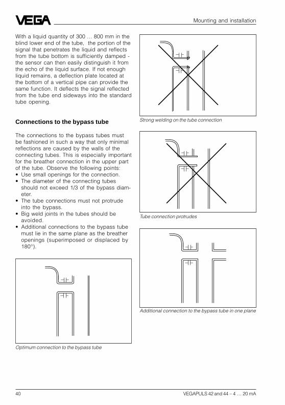
Optimum connection to the bypass tube
Strong welding on the tube connection
Tube connection protrudes
Additional connection to the bypass tube in one plane
Mounting and installation
With a liquid quantity of 300 … 800 mm in theblind lower end of the tube, the portion of thesignal that penetrates the liquid and reflectsfrom the tube bottom is sufficiently damped -the sensor can then easily distinguish it fromthe echo of the liquid surface. If not enoughliquid remains, a deflection plate located atthe bottom of a vertical pipe can provide thesame function. It deflects the signal reflectedfrom the tube end sideways into the standardtube opening.
Connections to the bypass tube
The connections to the bypass tubes mustbe fashioned in such a way that only minimalreflections are caused by the walls of theconnecting tubes. This is especially importantfor the breather connection in the upper partof the tube. Observe the following points:• Use small openings for the connection.• The diameter of the connecting tubes
should not exceed 1/3 of the bypass diam-eter.
• The tube connections must not protrudeinto the bypass.
• Big weld joints in the tubes should beavoided.
• Additional connections to the bypass tubemust lie in the same plane as the breatheropenings (superimposed or displaced by180°).
VEGAPULS 42 and 44 – 4 … 20 mA 41
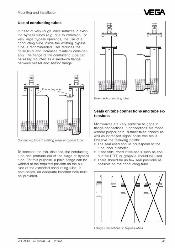
Conducting tube in existing surge or bypass tube
Extended conducting tube
Flange connections on bypass tubes
Mounting and installation
Conducting tube
Use of conducting tubes
In case of very rough inner surfaces in exist-ing bypass tubes (e.g. due to corrosion), orvery large bypass openings, the use of aconducting tube inside the existing bypasstube is recommended. This reduces thenoise level and increases reliability consider-ably. The flange of the conducting tube canbe easily mounted as a sandwich flangebetween vessel and sensor flange.
To increase the min. distance, the conductingtube can protrude out of the surge or bypasstube. For this purpose, a plain flange can bewelded at the required position on the out-side of the extended conducting tube. Inboth cases, an adequate breather hole mustbe provided.
Seals on tube connections and tube ex-tensions
Microwaves are very sensitive to gaps inflange connections. If connections are madewithout proper care, distinct false echoes aswell as increased signal noise can result.Observe the following points:• The seal used should correspond to the
tube inner diameter.• If possible, conductive seals such as con-
ductive PTFE or graphite should be used.• There should be as few seal positions as
possible on the conducting tube.
42 VEGAPULS 42 and 44 – 4 … 20 mA
ø 5...10
ø 5...10
Mounting and installation
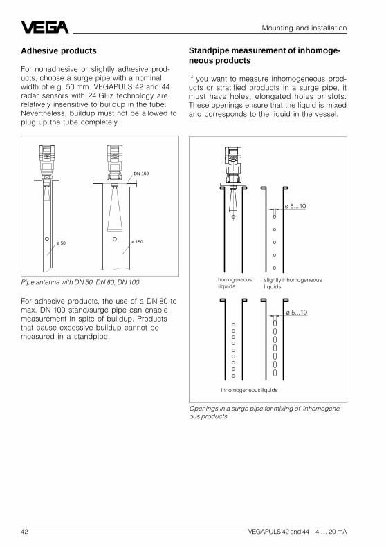
Openings in a surge pipe for mixing of inhomogene-ous products
slightly inhomogeneousliquids
inhomogeneous liquids
homogeneousliquids
Pipe antenna with DN 50, DN 80, DN 100
DN 150
ø 50 ø 150
Standpipe measurement of inhomoge-neous products
If you want to measure inhomogeneous prod-ucts or stratified products in a surge pipe, itmust have holes, elongated holes or slots.These openings ensure that the liquid is mixedand corresponds to the liquid in the vessel.
Adhesive products
For nonadhesive or slightly adhesive prod-ucts, choose a surge pipe with a nominalwidth of e.g. 50 mm. VEGAPULS 42 and 44radar sensors with 24 GHz technology arerelatively insensitive to buildup in the tube.Nevertheless, buildup must not be allowed toplug up the tube completely.
For adhesive products, the use of a DN 80 tomax. DN 100 stand/surge pipe can enablemeasurement in spite of buildup. Productsthat cause excessive buildup cannot bemeasured in a standpipe.

VEGAPULS 42 and 44 – 4 … 20 mA 43
Mounting and installation
ø50
> 300 mm
Tube antenna system with ball valve cutoff in measur-ing tube
Ball valve
Vent hole
The more inhomogeneous the measuredproduct, the closer the openings should bespaced.
Due to radar signal polarisation, the holes orslots must be positioned in two rows offsetby 180°.
The radar sensor must then be mounted sothat the type label of the sensor is alignedwith the rows of holes.
Every wider slot causes a false echo. Theslots should therefore not exceed a width of10 mm, to keep the signal-to-noise ratio at aminimum. Round slot ends are better thanrectangular ones.
Surge pipe with ball valve
If a ball valve is mounted in the surge pipe,maintenance and servicing can be carriedout without opening the vessel (e.g. if it con-tains liquid gas or toxic products).
Deflector
A prerequisite for trouble-free operation is aball valve throat that corresponds to the pipediameter and provides a flush surface withthe pipe inner wall. The valve must not haveany rough edges or constrictions in its chan-nel, and should be located at least 300 mmfrom the sensor flange.
ø 5...10
VEGAPULS 44: Rows of holes on one axis with thetype label
Type label
44 VEGAPULS 42 and 44 – 4 … 20 mA
Mounting and installation
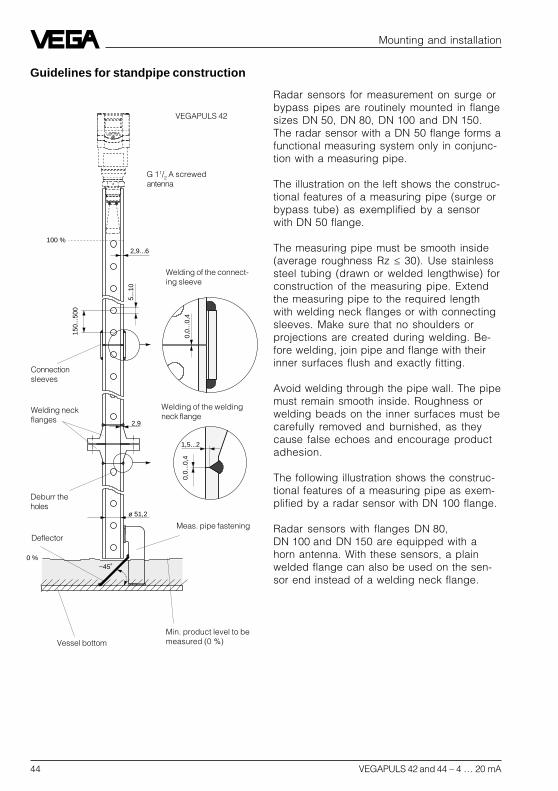
Guidelines for standpipe construction
Radar sensors for measurement on surge orbypass pipes are routinely mounted in flangesizes DN 50, DN 80, DN 100 and DN 150.The radar sensor with a DN 50 flange forms afunctional measuring system only in conjunc-tion with a measuring pipe.
The illustration on the left shows the construc-tional features of a measuring pipe (surge orbypass tube) as exemplified by a sensorwith DN 50 flange.
The measuring pipe must be smooth inside(average roughness Rz 30). Use stainlesssteel tubing (drawn or welded lengthwise) forconstruction of the measuring pipe. Extendthe measuring pipe to the required lengthwith welding neck flanges or with connectingsleeves. Make sure that no shoulders orprojections are created during welding. Be-fore welding, join pipe and flange with theirinner surfaces flush and exactly fitting.
Avoid welding through the pipe wall. The pipemust remain smooth inside. Roughness orwelding beads on the inner surfaces must becarefully removed and burnished, as theycause false echoes and encourage productadhesion.
The following illustration shows the construc-tional features of a measuring pipe as exem-plified by a radar sensor with DN 100 flange.
Radar sensors with flanges DN 80,DN 100 and DN 150 are equipped with ahorn antenna. With these sensors, a plainwelded flange can also be used on the sen-sor end instead of a welding neck flange.
0 %~45˚
ø 51,2
0,0.
..0,4
1,5...2
2,9
0,0.
..0,4
150.
..500
5...1
0
2,9...6
100 %
VEGAPULS 42
Connectionsleeves
Welding neckflanges
Welding of the connect-ing sleeve
Welding of the weldingneck flange
Meas. pipe fastening
Vessel bottom
Deflector
Min. product level to bemeasured (0 %)
Deburr theholes
G 11/2 A screwedantenna

VEGAPULS 42 and 44 – 4 … 20 mA 45
Mounting and installation
0 %
~45˚
ø 100,8
0,0…
0,4
1,5…2
3,6
0,0…
0,4
150…
500
5…10
3,6
ø 952
100 %
VEGAPULS 44
FlangeDN 100
ConnectingsleeveWelding neckflanges
Welding of the plainwelded flange
Welding of the connect-ing sleeves
Meas. pipe fastening
Vesselbottom
Deflector
Deburr theholes
If the vessel contains agitated products,fasten the measuring pipe to the vessel bot-tom. Provide additional fastenings for longermeasuring pipes.
When measuring products with lower dielec-tric values (< 4), a part of the radar signalpenetrates the medium. If the vessel is nearlyempty, an echo is generated by the mediumand the vessel bottom. In some cases, thevessel bottom generates a stronger signalecho than the product surface. With a deflec-tor on the measuring pipe end, the radarsignals are scattered. In nearly empty ves-sels and products with low dielectric value,the medium then generates a stronger echothan the vessel bottom.
Thanks to the deflector, only the useful signalis received in a nearly empty vessel - thecorrect measured value is thus transmittedand the 0 % level reliably detected.
Instead of a deflector, the standpipe or surgepipe can be equipped with a quadrant pipeat the end. This reflects the radar signals thatpenetrate the medium diffusely to the sideand reduces strong echoes from the tubeend or vessel bottom.
Welding of the weldingneck flange
0 %
0 %
Quadrant pipe on the bypass tube end
Quadrant pipe on the standpipe end

46 VEGAPULS 42 and 44 – 4 … 20 mA
Examples of flange and pipe dimensionsThe following shows a few examples of flanges and stainless steel pipes.
Plain welded flanges ND 6
D
b e 45˚
Db e 45˚k k
d 5 d 5
d 2d 2
D1 D1
Tube Flange Screws WeightNW D1 d5 D b e k No. Thread d2 kg
80 88.9 90.2 200 20 7 160 8 M16 18 3.79
100 108 109.6 220 20 7 180 8 M16 18 4.20114.3 115.9 4.03
150 159 161.1 285 22 7 240 8 M20 22 6.72168.3 170.5 6.57
Mounting and installation

VEGAPULS 42 and 44 – 4 … 20 mA 47
Tube Flange Neck Screws
NW D1 D b k h1 D3 s r H2 D4 f No. Thread D2
50 57 165 18 125 45 72 2.9 6 8 102 3 4 M16 1860.3 75
80 88.9 200 20 160 50 105 3.2 8 10 138 3 8 M16 18
100 108 220 20 180 52 125 3.6 8 12 158 3 8 M16 18114.3 131
150 159 285 22 240 55 175 4.5 10 12 212 3 8 M20 22168.3 184
Examples of pipe dimensions (drawn stainlesssteel pipe)
d
s
D
f bD4
D2
s H2
h1
D1
r
k
Welding neck flanges ND 16
Mounting and installation
D3
d (ø outer) s kg/m DN
57.00 2.90 3.493 50
88.90 3.20 7.112 80
108.00 3.60 9.411 100
114.30 3.60 9.979 100
159.00 4.50 17.409 150
48 VEGAPULS 42 and 44 – 4 … 20 mA
Mounting and installation
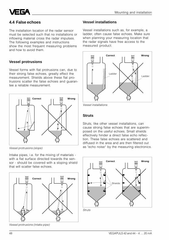
4.4 False echoes
The installation location of the radar sensormust be selected such that no installations orinflowing material cross the radar impulses.The following examples and instructionsshow the most frequent measuring problemsand how to avoid them.
Vessel protrusions
Vessel forms with flat protrusions can, due totheir strong false echoes, greatly effect themeasurement. Shields above these flat pro-trusions scatter the false echoes and guaran-tee a reliable measurement.
Intake pipes, i.e. for the mixing of materials -with a flat surface directed towards the sen-sor - should be covered with a sloping shieldthat will scatter false echoes.
Vessel protrusions (slope)
Vessel protrusions (intake pipe)
Correct Wrong
Correct Wrong
Vessel installations
Vessel installations such as, for example, aladder, often cause false echoes. Make surewhen planning your measuring location thatthe radar signals have free access to themeasured product.
Vessel installations
Correct Wrong
LadderLadder
Struts
Struts, like other vessel installations, cancause strong false echoes that are superim-posed on the useful echoes. Small shieldseffectively hinder a direct false echo reflec-tion. These false echoes are scattered anddiffused in the area and are then filtered outas "echo noise“ by the measuring electronics.
Struts
Correct Wrong
Shields

VEGAPULS 42 and 44 – 4 … 20 mA 49
75 %
0 %
100 %
Strong product movements
Buildup
Correct Wrong
Strong product movementsStrong turbulences in the vessel, e.g. causedby stirrers or intense chemical reactions, canseriously interfere with the measurement. Asurge or bypass tube (see illustration) ofsufficient size always allows, provided theproduct causes no buildup in the tube, areliable measurement even with strong turbu-lence in the vessel.
Inflowing material
Correct Wrong
Mounting and installation
Inflowing materialDo not mount the instrument in or above thefilling stream. Ensure that you detect theproduct surface and not the inflowing mate-rial.
BuildupIf the sensor is mounted too close to thevessel wall, buildup and adhesions of themeasured product to the vessel wall willcause false echoes. Position the sensor at asufficient distance from the vessel wall.Please also note chapter "4.1 General instal-lation instructions“.
Correct Wrong

50 VEGAPULS 42 and 44 – 4 … 20 mA
< 140 mm(250 mm)
Mounting and installation
4.5 Common installation mistakes
Socket piece too long
If the sensor is mounted in a socket exten-sion that is too long, false reflections arecaused, and measurement is hindered. Makesure that the horn antenna protrudes out ofthe socket piece.
Flange antenna: Correct and unfavourable socketlength
Flange antenna: Correct and unfavourable socketlength
Unfavour-able
Correct Unfavourable
Wrong
Mounting on a vessel with parabolic tank top
Correct
~ 1/2
vesselradius
Wrong
Correct
Parabolic effects on dished or archedvessel tops
Round or parabolic tank tops act like a para-bolic mirror on the radar signals. If the radarsensor is placed at the focal point of such aparabolic tank top, the sensor receives am-plified false echoes. The optimum mountingposition is generally in the range of half thevessel radius from the centre.
Reference plane

VEGAPULS 42 and 44 – 4 … 20 mA 51
Mounting and installation
Sensor too close to the vessel wall
If the radar sensor is mounted too close tothe vessel wall, strong false echoes can becaused. Buildup, rivets, screws or weld jointssuperimpose their echoes onto the productor useful echo. Please ensure sufficient dis-tance of the sensor to the vessel wall.
In case of good reflection conditions (liquidswithout vessel installations), we recommendselecting the sensor distance so that there isno vessel wall within the inner emission cone.For products in less favourable reflectionenvironments, it is a good idea to also keepthe outer emission cone free of interferinginstallations. Note chapter "4.1 General instal-lation instructions“.
Wrong orientation to the product
Weak measuring signals are caused if thesensor is not directly pointed at the productsurface. Orient the sensor axis perpendicu-larly to the product surface to achieve opti-mum measuring results.
Foam generation
Conductive foam is penetrated by the radarsignals to different depths and generates anumber of single (bubble) echoes. The sig-nals in the foam are also damped, like heatradiation that tries to penetrate styrofoam.Thick, dense, creamy foam, and especiallyconductive foam, on the product surface cancause incorrect measurements.
Foam generation
conductivefoam
Liquid
Direct sensor vertically to the product surface
Correct Wrong
LadderLadder
Take measures to avoid foam, measure in abypass tube or use a different measuringtechnology, e.g. capacitive electrodes orhydrostatic pressure transmitters.
In many cases, VEGAPULS 54 radar sensorswith 5.8 GHz operating frequency reachconsiderably better and more reliable meas-uring results in foam applications than type40 sensors with 24 GHz technology.
52 VEGAPULS 42 and 44 – 4 … 20 mA
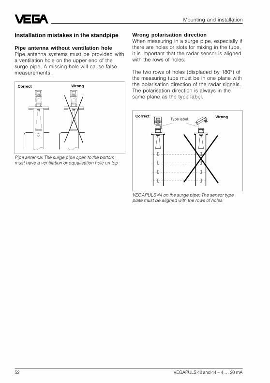
Pipe antenna: The surge pipe open to the bottommust have a ventilation or equalisation hole on top
Correct Wrong
VEGAPULS 44 on the surge pipe: The sensor typeplate must be aligned with the rows of holes.
Type labelCorrect Wrong
Mounting and installation
Installation mistakes in the standpipe
Pipe antenna without ventilation holePipe antenna systems must be provided witha ventilation hole on the upper end of thesurge pipe. A missing hole will cause falsemeasurements.
Wrong polarisation directionWhen measuring in a surge pipe, especially ifthere are holes or slots for mixing in the tube,it is important that the radar sensor is alignedwith the rows of holes.
The two rows of holes (displaced by 180°) ofthe measuring tube must be in one plane withthe polarisation direction of the radar signals.The polarisation direction is always in thesame plane as the type label.

VEGAPULS 42 and 44 – 4 … 20 mA 53
Electrical connection
5 Electrical connection
5.1 Connection and connection ca-ble
Safety information
As a rule, do all connecting work in the com-plete absence of line voltage. Always switchoff the power supply before you carry outconnecting work on the radar sensors. Pro-tect yourself and the instruments, especiallywhen using sensors which do not operate onlow voltage.
Qualified personnelInstruments which are not operated withprotective low voltage or DC voltage must beconnected only by qualified personnel.
Connecting and grounding
A standard two or four-wire cable (sensorswith separate supply) with max. 2.5 mm2 canbe used for connection. Very often the "elec-tromagnetic pollution“ by electronic actuators,energy cables and transmitting stations is soconsiderable that the two-wire cable or thefour-wire cable should be shielded.
We recommend the use of screened cable.Screening is also a good preventative meas-ure against future sources of interference.However, you must make sure that noground equalisation currents flow through thecable screening. Ground equalisation cur-rents can be avoided by ground potentialequalisation systems. When earthing on bothends, it is possible to connect the cableshield on one earth side (e.g. in the switchingcabinet) via a capacitor (e.g. 0.1 µF; 250 V)to the earth potential. Use a very low-resist-ance earth connection (foundation, plate ormains earth).
Note!In Ex applications, grounding on both ends isnot allowed due to potential transfer.
Ex protection
If an instrument is used in hazardous areas,the respective regulations, conformity certifi-cates and type approvals for systems in Exareas must be noted (e.g. DIN 0165).
Intrinsically safe circuits with more than oneactive instrument (instrument delivering elec-trical energy) are not allowed. Please note thespecial installation regulations (DIN 0165).
Connection cable
Please note that the connection cables arespecified for the expected operating tempera-tures in your systems. The cable must have anouter diameter of 5 … 9 mm (1/2 up to 1/3 inch)or Ex d housing 3.1 … 8.7 mm (0.12 … 0.34inch). Otherwise the seal effect of the cableentry will not be ensured.
Cables for intrinsically safe circuits must bemarked blue and must not be used for othercircuits.
Earth conductor terminal
On all VEGAPULS 44 sensors as well as theseries 42 sensors with metal thread, the earthconductor terminal is galvanically connectedwith the flange or the thread.

54 VEGAPULS 42 and 44 – 4 … 20 mA
Electrical connection
+ -
+ -
2.232
741(+) L1
2Communication
8765Display4-20mA
4-+3N
-
OK
+ ESCTank 1m (d)12.345
+ -
Display5 6 7 8
Communication2 -+
4-20mA1
2.23
272
-
OK
+ ESCTank 1m (d)12.345
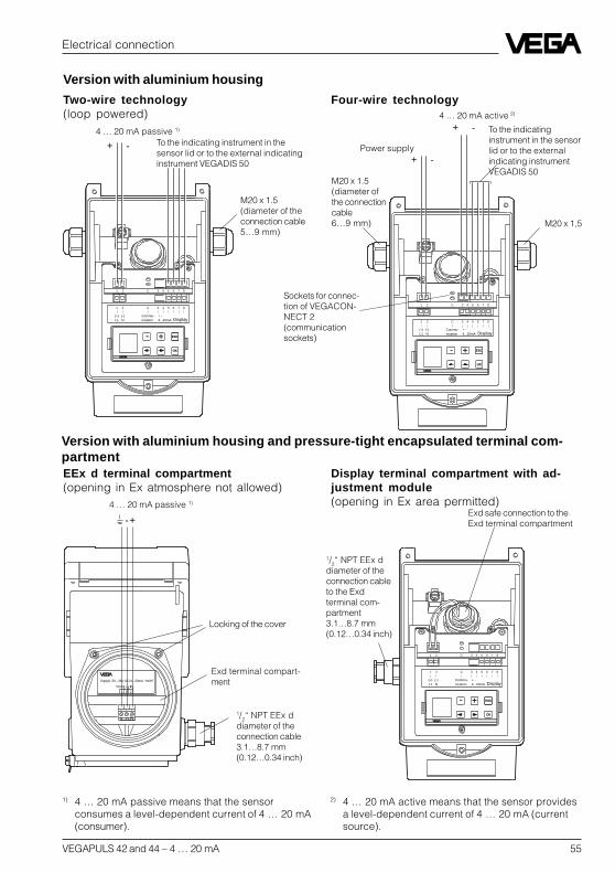
Power supply4 … 20 mA (passive) 1)
To the indicating instrument in thesensor lid or to the external indicatinginstrument VEGADIS 50
Sockets for connection ofthe HART® handheld orthe VEGACONNECT
Two-wire technology inplastic housing(loop powered)
Four-wire technology inplastic housing(separate supply)
Power supply
4 … 20 mA (active) 2)
Terminals(max. 2.5 mm2
wire cross-section)
Openingtabs
Pluggableadjustmentmodule MINI-COM
5.2 Connection of the sensor
After mounting the sensor at the measure-ment location according to the instructions inchapter "4 Mounting and installation“, loosenthe closing screw on top of the sensor. Thesensor lid with the optional indication displaycan then be opened. Unscrew the sleeve nutand slip it over the connection cable (afterremoving about 10 cm of insulation). Thesleeve nut of the cable entry has a self-lock-ing ratchet that prevents it from opening onits own.
Now insert the cable through the cable entryinto the sensor. Screw the sleeve nut backonto the cable entry and clamp the strippedwires of the cable into the proper terminalpositions.
The terminals hold the wire without a screw.Press the white opening tabs with a smallscrewdriver and insert the copper core of theconnection cable into the terminal opening.Check the hold of the individual wires in theterminals by lightly pulling on them.
1) 4 … 20 mA passive means that the sensorconsumes a level-dependent current of4 … 20 mA (consumer).
2) 4 … 20 mA active means that the sensor providesa level-dependent current of 4 … 20 mA (currentsource).
Version with plastic housing
Cable entryM20 x 1.5
To the display in the lid orthe external indicatinginstrument
VEGAPULS 42 and 44 – 4 … 20 mA 55
Electrical connection
- +2 1
Shield
Supply: 20...36V DC/4...20mA HART
1 2
-+
ESCESC+-
OKOK
1 2 C 5 6 7 843
(+) (-)L1 N
Commu-nication
+ -4...20mA Display
1 2 C 5 6 7 843
4 … 20 mA passive 1)
EEx d terminal compartment(opening in Ex atmosphere not allowed)
Display terminal compartment with ad-justment module(opening in Ex area permitted)
Exd terminal compart-ment
1/2“ NPT EEx ddiameter of theconnection cableto the Exdterminal com-partment3.1…8.7 mm(0.12…0.34 inch)
Exd safe connection to theExd terminal compartment
1/2“ NPT EEx ddiameter of theconnection cable3.1…8.7 mm(0.12…0.34 inch)
Version with aluminium housing and pressure-tight encapsulated terminal com-partment
Locking of the cover
ESCESC+-
OKOK
-+
-+
1 2 C 5 6 7 843
(+) (-)L1 N
Commu-nication
+ -4...20mA Display
1 2 C 5 6 7 843
ESCESC+-
OKOK
-+
1 2 C 5 6 7 843
(+) (-)L1 N
Commu-nication
+ -4...20mA Display
1 2 C 5 6 7 843
4 … 20 mA passive 1)
To the indicating instrument in thesensor lid or to the external indicatinginstrument VEGADIS 50
Two-wire technology(loop powered)
Four-wire technology
Power supply
4 … 20 mA active 2)
M20 x 1.5(diameter of theconnection cable5…9 mm)
M20 x 1.5(diameter ofthe connectioncable6…9 mm) M20 x 1,5
To the indicatinginstrument in the sensorlid or to the externalindicating instrumentVEGADIS 50
Version with aluminium housing
Sockets for connec-tion of VEGACON-NECT 2(communicationsockets)
1) 4 … 20 mA passive means that the sensorconsumes a level-dependent current of 4 … 20 mA(consumer).
2) 4 … 20 mA active means that the sensor providesa level-dependent current of 4 … 20 mA (currentsource).

56 VEGAPULS 42 and 44 – 4 … 20 mA
Electrical connection
SENSOR DISPLAY1 2 3 4 5 6 7 8
ESCESC+-
OKOK
-+
1 2 C 5 6 7 843
(+) (-)L1 N
Commu-nication
+ -4...20mA Display
1 2 C 5 6 7 843
- + ESC
OK
Tank 1m (d)12.345
5.3 Connection of the external indi-cating instrument VEGADIS 50
Loosen the four screws of the housing lid onVEGADIS 50.The connection procedure can be facilitatedby attaching the housing cover during con-nection work with one or two screws on theright side of the housing.
VEGADIS 50
ESCESC+-
OKOK
-+
1 2 C 5 6 7 843
(+) (-)L1 N
Commu-nication
+ -4...20mA Display
1 2 C 5 6 7 843
Four-wire sensor in aluminium housing(separate supply)
Two-wire sensor in aluminium housing(loop powered)
Screws
OUTPUT(to the sensor)
DISPLAY(in the lid of the indicatinginstrument)
4 … 20 mAactive
Power supply
Adjustmentmodule
4 … 20 mApassive
to VEGADIS 50 or to thedisplay in the sensor lid
M20x1,5
VEGAPULS 42 and 44 – 4 … 20 mA 57
Setup
VEGA signal conditioning instr Rx
VEGAMET 513, 514, 515, 602 50 … 100 Ohm
VEGAMET 614 no additionalVEGADIS 371 resistor
necessary
VEGAMET 601 200 … 250 Ohm
VEGASEL 643 150 … 200 Ohm
VEGAMET 513 S4, 514 S4515 S4, VEGALOG EA card 100 … 150 Ohm
6.2 Adjustment with PC
PC on the sensorFor connection of the PC to the sensor, theinterface converter VEGACONNECT 2 isrequired. It is plugged into the providedCONNECT socket in the sensor.
Make sure that the pins of VEGACONNECT 2are completely inserted into the sensor sock-ets, as the new pins have a slightly increasedresistance to insertion. The pins should beinserted up to a depth of approx. 13 mm to15 mm.
PC on the signal cableConnect the two-wire cable ofVEGACONNECT 2 to the signal cable of thesensor. If the resistance of the systems (PLC,current source etc.) connected to the signalcable is less than 250 a resistor of250 … 350 must be connected to the signalcable during adjustment (next page). Thedigital signals superimposed on the signalcable would otherwise be considerablydamped or even short-circuited due to insuf-ficient system resistance, resulting in faultycommunication with the PC.
When using a sensor in conjunction with aVEGA signal conditioning instrument, use acommunication resistor according to thefollowing schedule:
6 Setup
6.1 Adjustment methods
The radar sensors can be adjusted with- PC (adjustment program VVO)- with detachable adjustment module
MINICOM- with HART® handheld.The adjustment must be carried out with onlyone adjustment device. If, for example, youtry the parameter adjustment with the MINI-COM and the HART® handheld, the adjust-ment will not work.
PCThe adjustment program VVO (VEGA VisualOperating System) on the PC enables quickand easy adjustment of radar sensors. ThePC communicates via the interface adapterVEGACONNECT 2 with the sensor. Duringthe process, a digital adjustment signal issuperimposed on the signal and supplycable. The adjustment can be carried outdirectly on the sensor or at any desired loca-tion along the signal cable.
Adjustment module MINICOMWith the adjustment module MINICOM youadjust in the sensor or in the external indicat-ing instrument VEGADIS 50. With a dialoguetext display and 6 keys, the module offersthe same adjustment functionality as theadjustment software VVO.
HART® handheldVEGAPULS 42 and 44 radar sensors, likeother HART® protocol-compatible instruments,can be adjusted with the HART® handheld. Amanufacturer-specific DDD (Data-Device-Description) is not required. The radar sen-sors are adjusted with the HART® standardmenus. All main functions are accessible.Functions that are rarely used, such as, forexample, the scaling of the A/D converter forthe signal output or the adjustment with me-dium, are not possible or are blocked withthe HART® handheld. These functions mustbe carried out with the PC or the MINICOM.

58 VEGAPULS 42 and 44 – 4 … 20 mA
Rx
VEGAMET/VEGALOG
+
-
Ri ³ 250 W
250 W
+
-
Ri < 250 W
Setup
PLC
PLC

VEGAPULS 42 and 44 – 4 … 20 mA 59
Adjustment with the PC
In chapter "2.2 Configuration of measuringsystems“, connection of the PC to differentmeasuring systems is shown. The PC withthe adjustment program VVO version 2.60(VEGA Visual Operating) can be connectedto the- sensor- signal cable.
Note:Please note that for adjustment of VEGAPULS42 and 44 sensors, the adjustment programVVO version 2.60 or higher is required.
In the following setup and adjustment instruc-tions you will find information on the followingtopics and adjustment points:
• Configuration- configuration info- create new/modify measurement loop
• Parameter adjustment 1- measurement loop info- adjustment- conditioning/scaling
• Sensor optimisation- meas. environment/operating range- meas. environment/meas. conditions- meas. environment/sound velocity- echo curve- false echo storage
• Parameter adjustment 2 (optional)- linearisation- defining the linearisation curve by incre-
mental filling- calculating the linearisation curve- calculating a cylindrical tank- parameter adjustment current output and
sensor display• Simulation
Configuration and parameter adjust-ment
During the setup of the sensor you are con-fronted with two terms: "Configuration“ and"Parameter adjustment“. The meas. system isfirst set up with a configuration and then witha parameter adjustment.
Setup
ConfigurationThe term "Configuration“ means the basicadjustments of the meas. system. You informthe meas. system about the application (levelmeasurement, gauge, distance …), themeasurement loop name and the DCS outputaddress of the sensors. The configurationrepresents an electronic wiring and labellingof your sensor or, in other words, telling thesystem which sensor for what applicationand where.
Parameter adjustmentAfter the configuration, you carry out theparameter adjustment for each individualsensor. This means adjusting the sensors tothe respective operating range and adaptingthem to the specific application. You informthe sensor which product distance (whichlevel) is "empty“ and which "full“. This is calledadjustment. Here you choose in which physi-cal unit (volume, mass) and unit of measure-ment (m3, gal, liters …) the adjustedmeasured value should be outputted. In thesubmenu "Sensor optimisation“, you informthe sensor electronics about the actual envi-ronment, such as e.g. quick changes of themeasured value, foam generation, gas strati-fication, solid or liquid.
Before starting the setup:Do not be confused by the many pictures,adjustment steps and menus on the followingpages. Just carry out the setup with the PCstep by step and you will soon no longerneed the following instructions. Actions, likeentering a value or making a choice, areindicated in the following by a large blackdot, like this:• Choose …• Start …• Click to …
By this convention, the actions to be carriedout are clearly separated from supplemen-tary information in the following adjustmentinstructions.

60 VEGAPULS 42 and 44 – 4 … 20 mA
Setup
You have already connected the PC with theadjustment software VVO to your measuringsystem.
• Now switch on the power supply of theconnected sensor.
In the first 10 … 15 seconds the sensor startsto draw a current of approx. 22 mA (self-test)and immediately after, a level-proportional, i.e.,distance-proportional current of 4 … 20 mA.
• Switch on the PC and start the adjustmentsoftware VVO.
• Choose with the arrow keys or the mousethe item "Planning“ on the entrance screenand click to "OK“.
You are asked for the user identification.
• Enter under name "VEGA“.• Also enter "VEGA“ under password.
The adjustment program VEGA Visual Ope-rating (VVO), called in the following VVO,gets into contact with the connected sensor…
… and indicates after a few seconds if andwith which sensor a connection exists.
Note:When connecting the adjustment software(VVO) to a sensor from which data has al-ready been saved, you are asked if thesaved data should be transferred to thesensor or if you want to transfer the sensordata to the database of VVO (and the avail-able data of the current sensor will be over-written).
If you don’t get communication with the sen-sor, check the following:- Is the sensor being supplied with sufficient
voltage (min. 14 V)- When VEGACONNECT 2 is connected to
the signal cable, is the resistance of signalcable, processing system and load resist-ance 250 … 350
- Did you inadvertently use a VEGACON-NECT instead of the new VEGACON-NECT 2?
- Did you connect VEGACONNECT 2 toCOM1 on the PC?
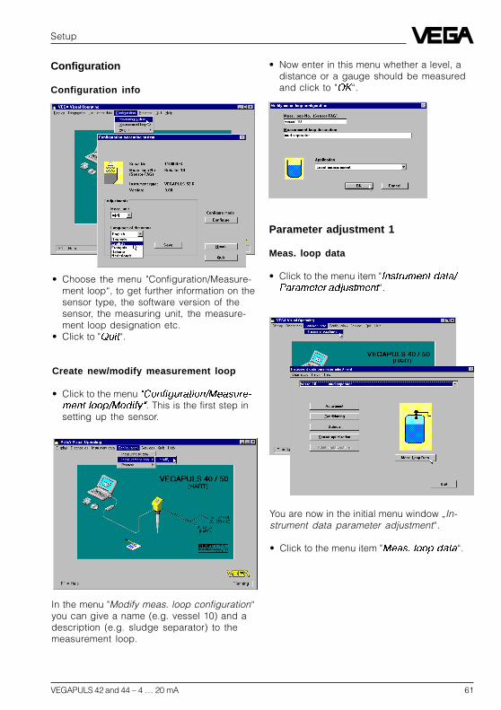
VEGAPULS 42 and 44 – 4 … 20 mA 61
Parameter adjustment 1
Meas. loop data
• Click to the menu item "Instrument data/Parameter adjustment“.
Setup
Configuration
Configuration info
• Choose the menu "Configuration/Measure-ment loop“, to get further information on thesensor type, the software version of thesensor, the measuring unit, the measure-ment loop designation etc.
• Click to "Quit“.
Create new/modify measurement loop
• Click to the menu "Configuration/Measure-ment loop/Modify. This is the first step insetting up the sensor.
• Now enter in this menu whether a level, adistance or a gauge should be measuredand click to "OK“.
In the menu "Modify meas. loop configuration“you can give a name (e.g. vessel 10) and adescription (e.g. sludge separator) to themeasurement loop.
You are now in the initial menu window „In-strument data parameter adjustment“.
• Click to the menu item "Meas. loop data“.

62 VEGAPULS 42 and 44 – 4 … 20 mA
You can carry out the min./max. adjustmentwith medium or without medium. Generallyyou will carry out the adjustment without me-dium. When you want to carry out the adjust-ment with medium, you have to carry out themin. adjustment with emptied vessel and themax. adjustment with filled vessel.
In the window “Measurement loop data”, allsensor data are displayed.
Adjustment
• Now choose the menu "Parameter adjust-ment“.
In the menu "Instrument data/Parameter ad-justment“ you now carry out all importantsensor adjustments. In the heading you nowsee the previously entered measurement loopname and the measurement loop description.
• Choose in the menu window "Instrumentdata parameter adjustment“ "Adjustment“.
Setup
• Click to "Min/Max-Adjustment“.
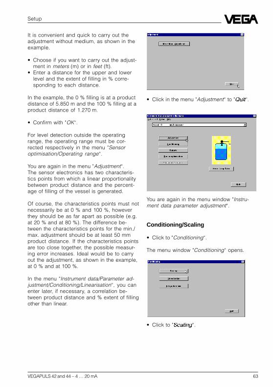
VEGAPULS 42 and 44 – 4 … 20 mA 63
Setup
It is convenient and quick to carry out theadjustment without medium, as shown in theexample.
• Choose if you want to carry out the adjust-ment in meters (m) or in feet (ft).
• Enter a distance for the upper and lowerlevel and the extent of filling in % corre-sponding to each distance.
In the example, the 0 % filling is at a productdistance of 5.850 m and the 100 % filling at aproduct distance of 1.270 m.
• Confirm with "OK“.
For level detection outside the operatingrange, the operating range must be cor-rected respectively in the menu "Sensoroptimisation/Operating range“.
You are again in the menu "Adjustment“.The sensor electronics has two characteris-tics points from which a linear proportionalitybetween product distance and the percent-age of filling of the vessel is generated.
Of course, the characteristics points must notnecessarily be at 0 % and 100 %, howeverthey should be as far apart as possible (e.g.at 20 % and at 80 %). The difference be-tween the characteristics points for the min./max. adjustment should be at least 50 mmproduct distance. If the characteristics pointsare too close together, the possible measur-ing error increases. Ideal would be to carryout the adjustment, as shown in the example,at 0 % and at 100 %.
In the menu "Instrument data/Parameter ad-justment/Conditioning/Linearisation“, you canenter later, if necessary, a correlation be-tween product distance and % extent of fillingother than linear.
• Click in the menu "Adjustment“ to "Quit“.
You are again in the menu window "Instru-ment data parameter adjustment“.
Conditioning/Scaling
• Click to "Conditioning“.
The menu window "Conditioning“ opens.
• Click to "Scaling“.

64 VEGAPULS 42 and 44 – 4 … 20 mA
Sensor optimisation
In the menu "Sensor optimisation" you adaptthe sensor to the specific meas. environment.
Meas. environment/Operating range
• Choose in the menu window "Instrumentdata parameter adjustment“ the menu item"Sensor optimisation.
Setup
In the menu "Scaling“, you allocate a unit ofmeasurement and a numerical value to the0 % and the 100 % values of the physicalquantity. You thereby inform the sensor, e.g.that at 0 % filling there are still 45 liters and at100 % filling 1200 liters in the vessel. Thesensor display then shows with empty vessel(0 %) 45 liters and with full vessel (100 %)1200 liters.
• First click to "Meas. environment.
As physical quantity you can choose "dimen-sionless (plain numbers), volume, mass,height and distance“ and assign an appro-priate unit of measurement (e.g. l, hl). Thesensor display then shows the measuredvalue in the selected physical quantity andunit.
• Save the adjustments in the menu "Scaling“by clicking "OK.
The adjustments are now transferred to thesensor.
• Click in the menu window "Meas. environ-ment“ to "Operating range“.

VEGAPULS 42 and 44 – 4 … 20 mA 65
Setup
With the menu item "Operating range“, youcan define the operating range of the sensordeviating from the "Min/Max adjustment“. Bydefault, the operating range correspondsotherwise to the min./max. adjustment, i.e. thespan.
Generally, it is better to choose the operatingrange approx. 5 % bigger than the adjustedmeasuring range (span) determined by themin./max. adjustment.In the example:- Min. adjustment to 1.270 m,- Max. adjustment to 5.85 m.In the example you would have set the oper-ating range from 1 m to 6 m.
• Save the adjustments and quit the menuwindow "Limitation of the operating range“.
Meas. environment/Meas. conditions
• Click to "Measuring conditions“.• In the menu window "Measuring condi-
tions“ you click on the options correspond-ing to your application.
After a few seconds during which the adjust-ments are permanently saved in the sensor,you are again in the window "Meas. environ-ment“.
Meas. conditions/Pulse velocity
In the menu item "Pulse velocity“ adjustmentsare only necessary when measuring in asurge or bypass tube (standpipe). Whenmeasuring in a standpipe, a shift of the run-ning time of the radar signal (dependent onthe inner diameter of the standpipe) occurs.To take this running time shift into account, itis necessary to inform the sensor in the menuof the tube inner diameter.
In the menu point "Pulse velocity“, it is addi-tionally possible to set manually a correctionfactor for the pulse velocity (light velocity) ofthe radar signal.
• Confirm with "OK.

66 VEGAPULS 42 and 44 – 4 … 20 mA
Setup
• If you want to make no adjustments, quitthis menu with "Quit“.
• With "OK“ you save the adjustments made.• Click in the menu window „Meas. environ-
ment“ to "Quit“.
You are again in the menu window „Sensoroptimisation“.
Echo curve
In the next illustration, you see the echo curveafter optimum directing of the sensor to theproduct surface (sensor axis perpendicularto the product surface). The false echo, e.g.caused by a strut, is now reduced by morethan 10 dB and will no longer influence themeasurement.
• Quit the menu "Echo curve“ with "Quit“.
False echo storage
With the menu item "Echo curve“ in the menuwindow "Sensor optimisation“, you can seethe course and the strength of the detectedradar echo. If, due to vessel installations, youexpect strong false echoes, a correction (ifpossible) of the mounting location and orien-tation (during simultaneous monitoring of heecho curve) can help localise and reduce thesize of the false echoes. In the following illus-tration, you see the echo curve with the falseecho nearly as large as the product echo(before correction of the sensor orientation,i.e. pointing it directly at the product surface).
With the menu item "False echo storage“ inthe menu "Sensor optimisation“, you canauthorise the sensor to save false echoes.The sensor electronics then saves the falseechoes in an internal database and assignsthem a lower level of importance than theuseful echo.

VEGAPULS 42 and 44 – 4 … 20 mA 67
Setup
• Click in the menu window "Sensor optimisa-tion“ to the menu item "False echo storage.
• Now click in the opening menu window"False echo storage“ to "Learn false ech-oes. The small window "Learn false ech-oes“ opens.
• Enter here the verified product distanceand click to "Create new.
You hereby authorise the sensor to mark allechoes before the product echo as falseechoes. This prevents the sensor from erro-neously detecting a false echo as level echo.
• Click to "Show echo curve.
The echo curve and the false echo markingare shown.
• Quit the menu with "Quit.
You are again in the menu window "Sensoroptimisation“.
With the menu item "Reset“ you reset all op-tions in the menu "Sensor optimisation“ todefault.
• Quit the menu window "Sensor optimisa-tion“ with "Quit.
Linearisation
If, in your vessel, there is a correlation otherthan linear between product distance and the% value of the filling, choose the menu item"Linearisation“ in the menu window "Condi-tioning“.
• Click to "Linearisation“.
The menu window "Linearisation“ opens.
A linear correlation between product distance(in %) and filling volume (in %) has beenpreset. Beside the two programmed lineari-sation curves "Cylindrical tank“ and "Spheri-cal tank“ you can also enter "userprogrammable curves“. Linear means thatthere is a linear correlation between level andvolume.

68 VEGAPULS 42 and 44 – 4 … 20 mA
The distance (product distance) outputtedby the sensor, if you have chosen "Distance“,is then:5.85 – (4.58 • 0.9579) = 1.463 m.If the index markers or value points of yourvessel are not known, you must gauge thevessel incrementally or calculate it with thevessel calculation program of VVO.
Defining the linearisation curve by incre-mental fillingIn the characteristics of the example, you seefour index markers or value pairs. There isalways a linear interpolation between theindex markers. The example vessel consistsof three cylindrical segments of differentheight and diameter. The middle segmenthas a considerably smaller diameter.
• Click in the check box "Show scaled val-ues“, to have the selected unit of measure-ment displayed on the y-axis (left bottompart in the menu window).
0 m
100 % at 1,27 m
1,463 m (95,79 %)
Span4,58 m(100 %)
4,387 m(95,79 %)
0 % at 5,85 m
User programmable linearisation curves
• Click to "User programmable curve“ toenter your own vessel geometry or a userprogrammable filling curve.
• Click to "Edit“.
The user-programmable linearisation curve isgenerated by index markers. Each indexmarker consists of a value pair. A value pairis composed of a value "Linearised“ and avalue "Percentage value“. “Percentage value”represents the percentage value of level."Linearised“ represents the percentage ofvessel volume at a certain percentage valueof the level.
In the field "Transfer measured value“ thecurrent level as a percentage of the adjustedspan is displayed. The measuring span hasalready been adjusted with the min./max.adjustment. In the example, the span is4.58 m and is between 5.85 m (empty) and1.27 m (full), see the following illustration.
5.85 m meas. distance correspond to 0 %level. 1.27 m meas. distance correspond to100 % level. The span is therefore 4.58 m(5.85 m – 1.27 m = 4.58 m).
A percentage value of 95.79 % then meansthat 4.387 of the adjusted span (4.58 m) hasbeen reached:4.58 • 0.9579 = 4.387 m.
Setup
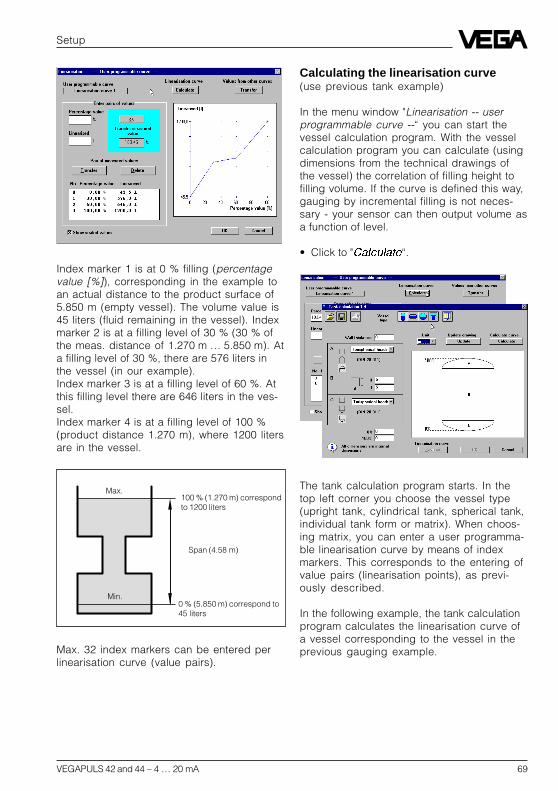
VEGAPULS 42 and 44 – 4 … 20 mA 69
Max.
Min.
100 % (1.270 m) correspondto 1200 liters
Span (4.58 m)
0 % (5.850 m) correspond to45 liters
Index marker 1 is at 0 % filling (percentagevalue [%]), corresponding in the example toan actual distance to the product surface of5.850 m (empty vessel). The volume value is45 liters (fluid remaining in the vessel). Indexmarker 2 is at a filling level of 30 % (30 % ofthe meas. distance of 1.270 m … 5.850 m). Ata filling level of 30 %, there are 576 liters inthe vessel (in our example).Index marker 3 is at a filling level of 60 %. Atthis filling level there are 646 liters in the ves-sel.Index marker 4 is at a filling level of 100 %(product distance 1.270 m), where 1200 litersare in the vessel.
Setup
Max. 32 index markers can be entered perlinearisation curve (value pairs).
Calculating the linearisation curve(use previous tank example)
In the menu window "Linearisation -- userprogrammable curve --“ you can start thevessel calculation program. With the vesselcalculation program you can calculate (usingdimensions from the technical drawings ofthe vessel) the correlation of filling height tofilling volume. If the curve is defined this way,gauging by incremental filling is not neces-sary - your sensor can then output volume asa function of level.
• Click to "Calculate“.
The tank calculation program starts. In thetop left corner you choose the vessel type(upright tank, cylindrical tank, spherical tank,individual tank form or matrix). When choos-ing matrix, you can enter a user programma-ble linearisation curve by means of indexmarkers. This corresponds to the entering ofvalue pairs (linearisation points), as previ-ously described.
In the following example, the tank calculationprogram calculates the linearisation curve ofa vessel corresponding to the vessel in theprevious gauging example.

70 VEGAPULS 42 and 44 – 4 … 20 mA
You are again in the menu window "Tankcalculation“.
• Click to „OK“ to save the tank calculation.
You are again in the menu window "Linearisa-tion -- user programmable curve --“. Thevolume percentages, with the correspondinglevel percentages, are shown as scaledvalues (liters in this example), if you haveclicked in the check box in the bottom leftcorner of the window.
Calculate cylindrical tank
• Click in the menu window "Linearisation --user programmable curve --“ to"Calculate“ and in the menu window "Tankcalculation“ to the symbol for cylindricaltanks.
Setup
• Click to "individual tank form and choosethree round tank segments with the dimen-sions 0.88 m • 0.9 m (height by diameter),0.66 m • 0.47 m and 0.66 m • 1.12 m (thistank form corresponds to the tank form ofthe gauging example).
• Click to "Calculate“.
After a short calculation time, the levels as apercentage of span and the correspondingvolume percentages are shown. Theoutputted curve shows this correlation in adiagram.
• Quit the linearisation table with „OK“.

VEGAPULS 42 and 44 – 4 … 20 mA 71
Setup
• Choose the "Meas. unit“, e.g. mm, thatshould apply to the entered vessel dimen-sions.
The following example shows how to enter acylindrical tank that is inclined by 3° and hasa cylinder length of 10000 mm and a diam-eter of 5000 mm. The cylindrical tank has a1500 mm wide, spherical form at the rightend and a dished tank form at the left.
In the bottom left corner in the menu window"Tank calculation“ you find the information "Alldimensions are internal dimensions“.
The entering of a wall thickness is only nec-essary for the calculation of the dished boilerend as its mathematical calculation is basedon the outer dimension.
The calculation program calculates by meansof the vessel inner dimensions the vesselvolume. Above the information "All dimensionsare internal dimensions“, you will find twofields with the percentage values 0 % and100 %. Here you can shift the 100 % line orthe 0 % line. In the example, the 100 % fillingline was defined at a distance of 650 mmfrom the upper vessel edge (inside).
• Click to "Calculate“.
You will get the calculated linearisation tableafter a short calculation time. By means of 32linearisation points, a function correlatingvessel volume to filling height is outputted.The example vessel has a filling of 216561liters at the 100 % line or of 216.6 m3. It ispossible to output the volume value in bar-rels, gallons, cubic yards or cubic feet.

72 VEGAPULS 42 and 44 – 4 … 20 mA
In the menu "Scaling“ (Instrument data/Condi-tioning/Scaling) you entered earlier that at0 % filling there are 45 liters in the tank and at100 % filling 1200 liters. The geometry of thecalculated cylindrical tank was accordinglyscaled down to a size that indeed evaluatesto a volume of only 1200 liters. The modifiedlinearisation curve was then applied to thevolume data that you entered in the menu"Scaling“.
If the true content of the calculated vesselshould be outputted, the volume that wasdetermined by the tank calculation programmust be entered in the menu "Scaling“.
The sensor then outputs the actual fillingvolume calculated from the entered vesseldimensions.
Setup
There is a linear interpolation between thelinearisation points.
• Click to "OK“ and you are again in themenu window "Tank calculation“.
• Again click in the menu window "Tank cal-culation“ to "OK“ and you are in the lineari-sation menu.
Here the calculated linearisation curve isagain outputted. The volume informationunder "Linearised“ now no longer corre-sponds to the calculated volume of the tankcalculation program.
Why?

VEGAPULS 42 and 44 – 4 … 20 mA 73
• Quit the menu with "OK“.• Confirm with "OK“ and your individual
linearisation curve is saved in the sensor.
Again in the menu window "Conditioning“, youcan enter with the menu item "Integrationtime“ a measured value integration. This isrecommended for agitated product surfaces,to prevent rapid fluctuation of the outputsignal and the measured value indication.The standard setting is an integration time of0 seconds.
• Quit the menu with "OK“.
You are again in the menu window "Instru-ment data parameter adjustment“.
• Quit the menu window with "OK“.
Parameter adjustment for current out-put and sensor display
• Choose "Instrument data parameter ad-justment“.
• Choose in the menu window "Instrumentdata parameter adjustment“ the menu item„Outputs“.
Setup
You are in the menu window "Outputs“.
Parameter adjustment current output
With the menu item "Current output“ youchoose the menu window "Current output“.Here you can adjust the signal condition ofthe 4 … 20 mA output signal.
• Click to "Save“, if you have made adjust-ments in this menu window.
• If the adjustments should remain un-changed, click to "Quit“.
You are again in the menu window "Outputs“.
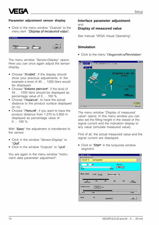
74 VEGAPULS 42 and 44 – 4 … 20 mA
The menu window "Display of measuredvalue“ opens. In this menu window you canalso set the filling height in the vessel or thesignal current and the indication display toany value (simulate measured value).
First of all, the actual measured value and thesignal current are displayed.
• Click to "Start“ in the turquoise windowsegment.
Interface parameter adjustmentandDisplay of measured value
See manual "VEGA Visual Operating“.
Simulation
• Click to the menu "Diagnostics/Simulation“.
Setup
The menu window "Sensor-Display“ opens.Here you can once again adjust the sensordisplay.
• Choose "Scaled“, if the display shouldshow your previous adjustments. In theexample a level of 45 … 1200 liters wouldbe displayed.
• Choose "Volume percent“, if the level of45 … 1200 liters should be displayed aspercentage value of 0 … 100 %.
• Choose "Distance“, to have the actualdistance to the product surface displayed(in m).
• Choose "Percent“, if you want to have theproduct distance from 1.270 to 5.850 mdisplayed as percentage value of0 … 100 %.
With "Save“ the adjustment is transferred tothe sensor.
• Click in the window "Sensor-Display“ to"Quit“.
• Click in the window "Outputs“ to "Quit“.
You are again in the menu window "Instru-ment data parameter adjustment“.
Parameter adjustment sensor display
• Click in the menu window "Outputs“ to themenu item "Display of measured value“.

VEGAPULS 42 and 44 – 4 … 20 mA 75
2
4
4 ... 20 mA
- + ESC
OK
Tank 1m (d)12.345
- + ESC
OK
Tank 1m (d)12.345
6.3 Adjustment with adjustmentmodule MINICOM
As with the PC, you can also adjust the sen-sor with the small, detachable adjustmentmodule MINICOM. The adjustment module issimply plugged into the sensor or into theexternal indicating instrument (optional).
For the adjustment with adjustment module,all sensor versions (adjustment options), aswith the PC and the adjustment programVVO, are available. There are some differ-ences, however, with MINICOM. It is notpossible to enter your own linearisationcurve.
You carry out all adjustment steps with the 6keys of the adjustment module. A small dis-play shows you, apart from the measuredvalue, a short message on the menu item orthe entered value of a menu adjustment.
The volume of information of the small display,however, cannot be compared with that of theadjustment program VVO, but you will soonget used to it and be able to carry out youradjustments quickly and efficiently with thesmall MINICOM.
Setup
The grey scroll bar becomes active. With thisscroll bar you can change the measuredvalue to any value in the range of-10 % … 110 % and thereby simulate thefilling or emptying of the vessel. In the inputbox of the turquoise window cutout you canenter any percentage value of filling.
Note on the simulation mode:One hour after the last simulation adjustment,the sensor automatically returns to standardoperating mode. The display of measuredvalue flashes during simulation.
Backup
See manual "VEGA Visual Operating“.

76 VEGAPULS 42 and 44 – 4 … 20 mA
2. Operating range
Without special adjustment, the operatingrange corresponds to the measuring range.Generally, it is useful to choose a slightlywider range (approx. 5 %) for the operatingrange than for the measuring range.
Example:Min./max. adjustment: 1.270 … 5.850 m;adjust operating range to approx. 1.000 …6.000 m.
Max.
Min.
100 % (1.270 m) correspondto 1200 liters
Span (4.58 m)
0 % (5.850 m) correspondsto 45 liters
3. Adjustment
Under the menu item "Adjustment“ you informthe sensor of the measuring range it shoulduse.
You can carry out the adjustment with orwithout medium. Generally you will carry outthe adjustment without medium, as you canthen adjust without an actual filling/emptyingcycle.
Error codes:E013 No valid measured value
- Sensor in the warm-up phase- Loss of the useful echo
E017 Adjustment span too smallE036 Sensor program not operating
- Sensor must be reprogrammed(service)
- Fault signal also appears duringprogramming
E040 Hardware failure, electronicsdefective
Adjustment steps
On pages 80 and 81 you will find the com-plete menu schematic of the adjustment mod-ule MINICOM.Set up the sensor in the numbered se-quence:1. Measuring tube adjustments (only for
measurement in a standpipe)2. Operating range3. Adjustment4. Conditioning5. Meas. conditions6. False echo storage (only required when
errors occur during operation).7. Indication of the useful and noise level8. OutputsShort explanations to the setup steps 1 … 8follow.
1. Measurement in a standpipe
Adjustment is only necessary, if the sensor ismounted in a standpipe (surge or bypasstube). When measuring in a standpipe, do asounding of the distance and correct thedisplay of measured value (which can differseveral percent from the sounded value)according to the sounding. From then on, thesensor corrects running time shift of the ra-dar signal and displays the correct value ofthe level in the standpipe (measuring tube).
Setup

VEGAPULS 42 and 44 – 4 … 20 mA 77
With the "+“ or "–“ key you canassign a level distance (exam-ple 5.85 m) to the previouslyadjusted percentage value. Ifyou do not know the distance,you have to do a sounding.
The adjusted product dis-tance is written in the sensorand the display stops flash-ing.
You thereby adjusted the lower product dis-tance as well as the percentage filling valuecorresponding to the lower product distance.
Note:For level detection outside the operating range,the operating range must be corrected accord-ingly in the menu "Sensor optimisation/Opera-ting range“.
OK
+ –or
100.0%at
m (d)XX.XXX
(max. adjustment)
Now you make the max. adjustment (upperproduct distance) (example: 100 % and1.270 m product distance). First enter the per-centage value and then the product distancecorresponding to the percentage value.
Note:The difference between the adjustment val-ues of the lower product distance and theupper product distance should be as big aspossible, preferably at 0 % and 100 %. If thevalues are very close together, e.g. lowerproduct distance indication at 40 % (3.102 m)and upper product distance adjustment at45 % (3.331 m), the measurement will beinaccurate. A characteristic curve is gener-ated from the two points. Even the smallestdeviations between actual product distanceand entered product distance will consider-ably influence the slope of the characteristiccurve. If the adjustment points are too closetogether, small errors inflate to considerablylarger ones when the 0 % or the 100 % valueis outputted.
Adjustment without medium(adjustment independent of the level)
Key Display indication
Setup
Adjust-ment
Para-meter
Sensor
m(d) 4.700
w.omedium
Adjust-mentin
m(d)
(min. adjustment)
OK
OK
+
OK
OK
OK
Adjust-mentin
m(d)
0.0%at
m (d)XX.XXX
OK
+ –or
The distance indication flashesand you can choose "feet“ and"m“.
Confirm the adjustment with"OK“.
With "+“ and "–“ you adjust thepercentage value for the min.value (example 0.0 %).
The adjusted percentagevalue is written in the sensorand the distance of the min.value corresponding to thepercentage value flashes.

78 VEGAPULS 42 and 44 – 4 … 20 mA
• Confirm with "OK“.
If necessary, choose a decimal point. How-ever, note that only max. 4 digits can bedisplayed. In the menu "prop. to“ you choosethe physical quantity (mass, volume, dis-tance…) and in the menu "Unit“ the physicalunit (kg, l, ft3, gal, m3 …).
Linearisation:
Lin.curve
Linear
Integrationtime
0 s
Adjustment
Signalconditioning
Scaling
A linear correlation between the percentagevalue of the product distance and percent-age value of the filling volume is preadjusted.With the menu "Lin. curve“ you can choosebetween linear, spherical tank and cylindricaltank. The generation of a customized lineari-sation curve is only possible with the PC andthe adjustment program VVO.
5. Meas. conditions
(see menu plan no. 5)Choose „Liquid“ or „Solid“ and select theoptions corresponding to your application.
6. False echo storage
A false echo storage is always useful whenunavoidable false echo sources (e.g. struts)must be minimised. By creating a false echostorage, you authorise the sensor electronicsto record the false echoes and save them inan internal database. The sensor electronicstreats these (false) echoes differently fromthe useful echoes and filters them out.
Setup
withmedium
Min.adjustat %
XXX.X
Max.adjustat %
XXX.X
Signalconditioning
Scaling
0 %corresponds
XXXX
100 %corresponds
XXXX
Deci-malpoint888.8
prop.to
Mass
Unit
Kg
Adjustment with medium
Fill the vessel e.g. to 10 % and enter 10 % inthe menu "Min. adjust“ with the "+“ and "–“keys. Then fill the vessel, e.g. to 80 % or100 % and enter 100 % in the menu "Max.adjust“ with the "+“ and "–“ keys.
4. Conditioning
Under the menu item "Conditioning“ you as-sign a product distance at 0 % and at 100 %filling. Then you enter the parameter and thephysical unit as well as the decimal point.
Enter in the menu window "0 % corresponds“the numerical value of the 0 % filling. In theexample of the adjustment with the PC andthe adjustment software VVO this would be45 for 45 liters.
• Confirm with "OK“.
With the "—>“ key you change to the 100 %menu. Enter here the numerical value of yourparameter corresponding to a 100 % filling.In the example 1200 for 1200 liters.

VEGAPULS 42 and 44 – 4 … 20 mA 79
Setup
Ampl.:XX dB
S-N:XX dB
7. Signal-Noise divergence
In the menu
you get important information on the signalquality of the product echo. The higher the "S-N“ value, the more reliable the measure-ment (menu schematic MINICOM).
Ampl.: means amplitude of the level echo indB (useful level)
S-N: means Signal-Noise, i.e. the usefullevel minus the level of the back-ground noise
The bigger the "S-N“ value (difference be-tween the amplitudes of the useful signal leveland the noise level), the better the measure-ment:> 50 dB Measurement excellent40 … 50 dB Measurement very good20 … 40 dB Measurement good10 … 20 dB Measurement satisfactory5 … 10 dB Measurement sufficient< 5 dB Measurement poor
Example:Ampl. = 68 dBS-N = 53 dB
68 dB – 53 dB = 15 dB
This means that the noise level is only68 dB – 53 dB = 15 dB.
A 15 dB noise level with a 53 dB higher signallevel would ensure a high degree of meas-urement reliability.
8. Outputs
Under the menu "Outputs“ you determine, forexample, if the current output should beinverted, or in which unit of measurement themeasured value should appear in the sensordisplay.

80 VEGAPULS 42 and 44 – 4 … 20 mA
Setup
Menu schematic for the adjustment module MINICOM
Sensoropti-mize
Para-meter
Sensor
m(d) 4.700
Meas.environment
Opera-tingrange
Begin
m (d) 0.50
End
m (d) 6.00
Meas.conditions
Measuring intube
CorrectionNow
OK
Tubediametmm (d)
50
PULS44K2.00
When switching on, the sensortype and the software version aredisplayed for a few seconds.
2. 5. 1.
CorrectionNow
OK
Correctionfactor
2,50 %
Confi-gura-tion
SensorTag
Sensor
Sensoraddr.
0
Meas.unit
m (d)
Adjustment
Signalconditioning
w.outmedium
Adjustmentin
m(d)
withmedium
0.0 %at
m (d)XX.XXX
100.0%at
m (d)XX.XXX
Min-adjustat %
XXX.X
Max-adjustat %
XXX.X
Sca-ling
Lin.curve
Linear
Integrationtime
0 s
0 %corresponds
XXXX
100 %corresponds
XXXX
Deci-malpoint888.8
Prop.to
Mass
Unit
Kg
3. 4.
Condition
liquid
Agitated surface No
Foam-ingprod. No
Fastchange
No
Meas-ure intube No
Multipleecho No
Low DKpro-duct No
Condition
solid
Highdustlevel No
Largeanglerepose No
Fastchange
No
Multipleecho No
Multidrop operation (HART® sensoraddress):• Sensor address zero: The sensor outputs
beside the 4…20 mA signal also a digital(HART®) level signal.
• Sensor address 1…15: the sensor deliversonly a digital (HART®) level signal. Thesensor current is frozen to 4 mA (powersupply).

VEGAPULS 42 and 44 – 4 … 20 mA 81
Setup
Createnew
Act.dist.
m (d) 4.700
Falseechomemory
UpdateNow
OK
Meas.dist.
m (d) X.XX
Learn-ing
Update
UpdateNow
OK
Learn-ing
Delete
Delet-ing
DeleteNow
OK
Add’lfunc-tions
Info Lan-guageEng-lish
ResetNow
OK
Reseting
Basicreset
SensortypePULS54K
Serialnumber
10940213
Softw.vers.
2.00
Act.dist.
m (d)4.700
max.range
m (d)7.000
SensorTag
Sensor
Softw.date15.09.1999
Meas.dist.
m (d) X.XX
Ampl.:XX dB
S-N:XX dB
Ampl.:XX dB
S-N:XX dB
With these keys you move inthe menu field to the left, right,top and bottom
6. 7.
ESC
OK
Simulation:
One hour after the last simulationadjustment the sensor returnsautomatically to normal operatingmode.
Sensoraddr.
0
Foam-ingprod Yes
Act.dist. m X,XX
Light grey menu fields are onlydisplayed if required (dependenton the adjustments in othermenus).
Menu items in bolt print providesensor and measured valueinformation and cannot bemodified in this position.
Fastchange
No
White menu items can bemodified with the "+“ or "–“ keyand saved with the "OK“ key.
Simu-lation
Simu-lationNow!
OK
Simu-lation
%XXX.X
Out-puts
Curr.out-put
Sensordispl.
Fail-uremode22mA
Prop.todi-stance
Curr-out-put4-20mA
8.
Act.current
mA8.565
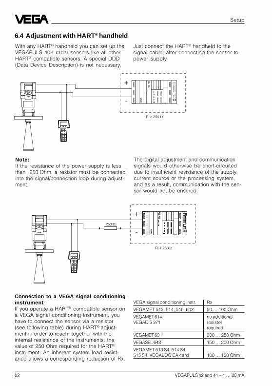
82 VEGAPULS 42 and 44 – 4 … 20 mA
Connection to a VEGA signal conditioninginstrumentIf you operate a HART® compatible sensor ona VEGA signal conditioning instrument, youhave to connect the sensor via a resistor(see following table) during HART® adjust-ment in order to reach, together with theinternal resistance of the instruments, thevalue of 250 Ohm required for the HART®
instrument. An inherent system load resist-ance allows a corresponding reduction of Rx.
VEGA signal conditioning instr. Rx
VEGAMET 513, 514, 515, 602 50 … 100 Ohm
VEGAMET 614 no additionalVEGADIS 371 resistor
required
VEGAMET 601 200 … 250 Ohm
VEGASEL 643 150 … 200 Ohm
VEGAMET 513 S4, 514 S4515 S4, VEGALOG EA card 100 … 150 Ohm
Setup
Just connect the HART® handheld to thesignal cable, after connecting the sensor topower supply.
Note:If the resistance of the power supply is lessthan 250 Ohm, a resistor must be connectedinto the signal/connection loop during adjust-ment.
The digital adjustment and communicationsignals would otherwise be short-circuiteddue to insufficient resistance of the supplycurrent source or the processing system,and as a result, communication with the sen-sor would not be ensured.
+
-
Ri ³ 250 W
250 W
+
-
Ri < 250 W
With any HART® handheld you can set up theVEGAPULS 40K radar sensors like all otherHART® compatible sensors. A special DDD(Data Device Description) is not necessary.
6.4 Adjustment with HART® handheld
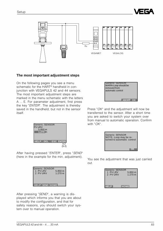
VEGAPULS 42 and 44 – 4 … 20 mA 83
Setup
Rx
VEGAMET VEGALOG
The most important adjustment steps
On the following pages you see a menuschematic for the HART® handheld in con-junction with VEGAPULS 42 and 44 sensors.The most important adjustment steps aremarked in the menu schematic with the lettersA … E. For parameter adjustment, first pressthe key "ENTER“. The adjustment is therebysaved in the handheld, but not in the sensoritself.
After pressing "SEND“, a warning is dis-played which informs you that you are aboutto modify the configuration, and that forsafety reasons, you should switch your sys-tem over to manual operation.
4.2(5.2)
After having pressed "ENTER“, press "SEND“(here in the example for the min. adjustment).
Press "OK“ and the adjustment will now betransferred to the sensor. After a short timeyou are asked to switch your system overfrom manual to automatic operation. Confirmwith "OK“.
You see the adjustment that was just carriedout.
Generic: SENSOR1 PV LRV 5.850 m2 PV URV 1.270 m
HELP SEND HOME
Generic: SENSORPV URV
5.850 m1.270 m
HELP DEL ESC ENTER
Generic: SENSOR WARN-Loop should be removed from automatic control
ABORT OK
Generic: SENSORNOTE- Loop may be re-turned to automatic control
OK
Generic: SENSOR1 PV LRV 5.850 m2 PV URV 1.270 m
HELP HOME

84 VEGAPULS 42 and 44 – 4 … 20 mA
HART® menu schematic VEGAPULS 42 and 44
Setup
A
6 PV Dämpfung
1
2
3
4
5
1.1
1.2
1.3
1.4
4.1(5.1)
4.2(5.2)
1.4.3
1.3.11.3.2
not necessary1.3.4
1.3.6
1.2.2
B
Switch on:
after approx.20 s
(max.meas.distance)
(min.meas.distance)Continue as under figure 4
linear
not necessary
Important andnecessary menuwindows
Less importantmenu windows
Hart Communicator
Self Testin Progress
Firmware Rev: F2.2Module Rev: 3.6
01992-96 FRSI
Generic: SENSORDiag/Service
1 Test device2 Loop test3 Calibration4 D/A trim
SAVE HOME
Generic: SENSORDetailed setup
1 Sensors2 Signal condition3 Output condition4 Device information
SAVE HOME
Generic: SENSORBasic setup
1 Tag2 PV Unit3 Range values4 Device information5 PV xfer fnctn
HELP SAVE HOME
Generic: SENSORProcess variables
1 Snsr 2.281 m2 AI % rnge 69,140 %3 AO 1 15.059 mA
HELP SAVE HOME
Generic: SENSOROnline(Generic)
1 Device setup2 PV 2.281 m3 PV AO 15.059 mA4 PV LRV 20.000 m5 PV URV 0.000 m
SAVE
Generic: SENSORDevice setup
1 Process variables2 Diag/Service3 Basic setup4 Detailed setup5 Review
SAVE HOME
Generic: SENSORPV
2.281 m
HELP EXIT
Generic: SENSORAA1
15.264 mA
HELP EXIT
Generic: SENSOR1 PV LRV 20.000 m2 PV URV 0.000 m
HELP HOME
Generic: SENSORPV URV
0.000 m0.300 m
HELP DEL ESC ENTER
Generic: SENSORPV LRV
20.000 m5.850 m
HELP DEL ESC ENTER
Generic: SENSOR1 PV LRV
20.000 m2 PV URV 0.000 m
HELP HOME

VEGAPULS 42 and 44 – 4 … 20 mA 85
Setup
1.1.3
1.1.2
1.3.1
1.3.2
1.3.4
1.3.66 Write protect None7 Descriptor8 Message9 PV Sensr s/n
Final asmbly numRevision #’s
1.3.4.21.3.4.31.3.4.4
1.3.4.5
1.3.4.71.3.4.8
1.3.4.91.3.4.101.3.4.11
1.3.4.1
see nextpage
1.3.4.6
C
1.2.2
Switch offcontrol
Individual current values for testpurposes (measured value simula-tion).See also menu window 1.4.3.1.on the next page
The following menu windows are notsupported by the sensor. Saving of adjust-ments carried out here is not possible.
The adjustment of actual "empty“ or "full“measured values should be carried out inthe menu window 4.1 and 4.2. Enter therethe meas. distance with empty vessel aszero and the meas. distance with fullvessel as end.
Sensor serial number
E
1.4.3
1.4.3.2
OFF: Sensor signals measured values only on requestON: Sensor signals measured values unrequested
1.4.3.2
D
like menu 1.3.1
see nextpage
1.4.3.1
Multidrop operation (sensor address):The sensor outputs beside the 4 … 20 mAsignal also a digital (HART®) level signal:• Enquiry address zero, the sensor
consumes a level dependent 4 … 20 mAcurrent and delivers a digital (HART®)level signal.
• Enquiry address 1 … 15, the sensordelivers a digital (HART®) level signaland the sensor current is frozen to 4 mA(power supply).The 4 … 20 mA signal is no longeravailable.
Generic: SENSORPV
2.281 m
HELP EXIT Generic: SENSORA01
8.264 mA
HELP EXIT
Generic: SENSORPV % rnge
45.390 %
HELP EXIT
Generic: SENSORPV Damp
0.000 s0.000 s
HELP DEL ESC ENTER
Generic: SENSORDevice information
1 Distributor2 Model3 Dev id4 Tag5 Date 01/01/97
HELP SAVE HOME
Generic: SENSORPV Snsr unitm
mbblincm
ESC ENTER
Generic: SENSORTag
SENSORSENSOR
HELP DEL ESC ENTER
Generic: SENSORChoose analog outputlevel
1 4mA2 20mA3 Other4 End
ABORT ENTER
Generic: SENSOROutput condition
1 Analog output2 HART output
SAVE HOME
Generic: SENSORHART output
1 Poll addr 02 Num req preams 03 Burst mode4 Burst option
HELP SAVE HOME
Generic: SENSORPoll addr
00
HELP DEL ESC ENTER
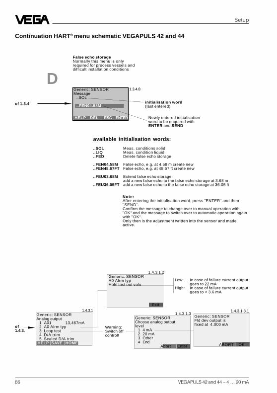
86 VEGAPULS 42 and 44 – 4 … 20 mA
Setup
Continuation HART® menu schematic VEGAPULS 42 and 44
1.3.4.8
available initialisation words:
..SOL Meas. conditions solid
..LIQ Meas. condition liquid
..FED Delete false echo storage
..FEN04.58M False echo, e.g. at 4.58 m create new
..FEN48.67FT False echo, e.g. at 48.67 ft create new
..FEU03.68M Extend false echo storage:add a new false echo to the false echo storage at 3.68 m
..FEU36.05FT add a new false echo to the false echo storage at 36.05 ft
initialisation word(last entered)
Newly entered initialisationword to be enquired withENTER and SEND
D
Note:After entering the initialisation word, press "ENTER“ and then"SEND“.Confirm the message to change over to manual operation with"OK“ and the message to switch over to automatic operation againwith "OK“.Only then is the adjustment written into the sensor and madeactive.
1.4.3.1
1.4.3.1.2
Low: In case of failure current outputgoes to 22 mA
High: In case of failure current outputgoes to < 3.6 mA
1.4.3.1.31.4.3.1.3.1
Warning:Switch offcontrol!
False echo storageNormally this menu is onlyrequired for process vessels anddifficult installation conditions
of 1.3.4
of1.4.3.
Generic: SENSORMessage
..SOL
..FEN04.58M
HELP DEL ESC ENTER
Generic: SENSORAnalog output
1 A01 13,467mA2 A0 Alrm typ3 Loop test4 D/A trim5 Scaled D/A trim
HELP SAVE HOME
Generic: SENSORChoose analog outputlevel
1 4 mA2 20 mA3 Other4 End
Abort Enter
Generic: SENSORFld dev output isfixed at 4.000 mA
ABORT OK
Generic: SENSORA0 Alrm typHold last out valu
Exit

VEGAPULS 42 and 44 – 4 … 20 mA 87
Diagnostics
7 Diagnostics
7.1 Simulation
For simulation of a certain filling, you can callup the function “Simulation” in the adjustmentmodule MINICOM, in the software programVVO or in the HART® handheld.You simulate a vessel filling level and therebya certain sensor current. Please note thatconnected instruments, such as e.g. a PLCreact according to their adjustments and willprobably activate alarms or system func-tions. One hour after the last simulation ad-justment, the sensor returns automatically tostandard operating mode.
7.2 Error codes
Error codes Rectification
E013 No valid measured value Message is displayed during warm-up phase- Sensor in the warm-up phase- Loss of the useful echo If the message remains, a false echo storage
must be made with the adjustment moduleMINICOM in the menu “sensor optimisation” orbetter, with the PC and VVO.If the message still remains, carry out a newadjustment.
E017 Adjustment span too small Carry out a readjustment.Make sure that the difference betweenmin. and max. adjustment is at least 10 mm.
E036 Sensor software does not run Sensor must be programmed with new software(service).Message appears during a software update.
E040 Hardware failure/Electronics defec- Check all connection cables.tive Contact our service department.

HiTECH Technologies, Inc. 301 Oxford Valley Road - Building 505
Yardley, PA 19067-7706 Tel: 215. 321. 6012; Fax: 215. 321. 6067
Tech Support (Toll Free) 866-DrLevel or 888-NIVELCO Email: [email protected] or [email protected] Web Site: www.DrLevel.com or www.hitechtech.com
A TECHNOLOGY FOR EVERY LEVEL APPLICATION