Embed Size (px)
Citation preview

LINAX A315 Modbus connection Be 09.15
Camille Bauer Metrawatt AGAargauerstrasse 7CH-5610 Wohlen/SwitzerlandTel +41 56 618 21 11Fax +41 56 618 21 [email protected]
Operating Instructions Universal Data ManagerModbus-SlaveModbus connection via TCP or RS485LINAX A315
Universal Data Manager/Modbus Slave ___________________________________________________________________________________
2
Table of contents: 1 General information ..................................................................................................................................................... 3
1.1 Prerequisites .......................................................................................................................................................... 3 1.2 Modbus RTU connection ....................................................................................................................................... 3 1.3 Modbus TCP connection ....................................................................................................................................... 3
1.3.1 Transfer LED ................................................................................................................................................... 3 1.3.2 Link LED .......................................................................................................................................................... 3
1.4 Functional description .......................................................................................................................................... 4 1.5 Checking the availability of the Modbus Slave function ................................................................................... 4
2 Settings in the setup ..................................................................................................................................................... 5 2.1 Modbus TCP, RS485 .............................................................................................................................................. 5 2.2 Universal channels ................................................................................................................................................ 6
2.2.1 Data transfer: Modbus Master -> device: .................................................................................................... 6 2.2.2 Data transfer: device -> Modbus Master: .................................................................................................... 6
2.3 Mathematics channels .......................................................................................................................................... 6 2.3.1 Data transfer: device -> Modbus Master: .................................................................................................... 6
2.4 Digital channels ..................................................................................................................................................... 7 2.4.1 Data transfer: Modbus Master -> device: .................................................................................................... 7 2.4.2 Data transfer: device -> Modbus Master: .................................................................................................... 7
2.5 General information .............................................................................................................................................. 8 2.6 Addressing ............................................................................................................................................................. 9
2.6.1 Modbus Master -> device: instantaneous value of universal channels ................................................... 9 2.6.2 Modbus Master -> device: digital input state ........................................................................................... 11
2.6.2.1 Writing all the states simultaneously ................................................................................................. 11 2.6.2.2 Writing states individually ................................................................................................................... 12
2.6.3 Device -> Modbus Master: universal channels (instantaneous value) .................................................. 13 2.6.4 Device -> Modbus Master: math channels (result) .................................................................................. 15 2.6.5 Device -> Modbus Master: digital channels (state) .................................................................................. 18
2.6.5.1 Reading out all the states simultaneously ......................................................................................... 18 2.6.5.2 Reading out states individually ........................................................................................................... 19
2.6.6 Device -> Modbus Master: digital channels (totalizer) ............................................................................ 20 2.6.7 Device -> Modbus Master: integrated universal channels (totalizer) .................................................... 22 2.6.8 Device -> Modbus Master: integrated math channels (totalizer)........................................................... 24 2.6.9 Device -> Modbus Master: reading relay states........................................................................................ 26 2.6.10 Structure of the process values ................................................................................................................. 27
2.6.10.1 32-bit floating point number (IEEE-754) ........................................................................................ 27 2.6.10.2 64-bit floating point number (IEEE-754) ........................................................................................ 27 2.6.10.3 Limit value violations ......................................................................................................................... 28 2.6.10.4 Status of the floating point numbers................................................................................................ 29
3 Overview of registers .................................................................................................................................................. 30 4 List of abbreviations/glossary of terms .................................................................................................................... 32 5 Index ............................................................................................................................................................................. 32
Universal Data Manager/Modbus Slave ___________________________________________________________________________________
3
1 General information Please pay attention to the following signs:
Note: Information and tips for safe commissioning
Caution: Failure to observe the caution sign can result in a device defect or a malfunction!
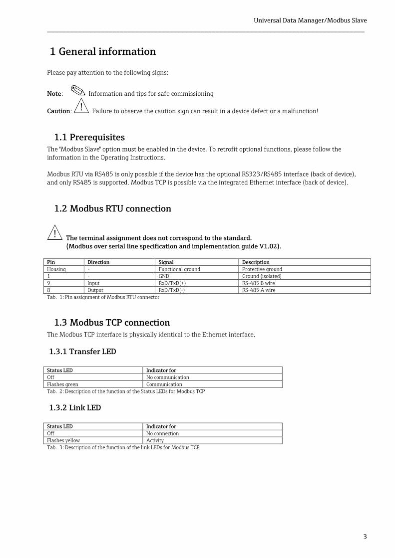
1.1 Prerequisites The "Modbus Slave" option must be enabled in the device. To retrofit optional functions, please follow the information in the Operating Instructions. Modbus RTU via RS485 is only possible if the device has the optional RS323/RS485 interface (back of device), and only RS485 is supported. Modbus TCP is possible via the integrated Ethernet interface (back of device).
1.2 Modbus RTU connection
The terminal assignment does not correspond to the standard. (Modbus over serial line specification and implementation guide V1.02).
Pin Direction Signal Description
Housing - Functional ground Protective ground 1 - GND Ground (isolated)
9 Input RxD/TxD(+) RS-485 B wire 8 Output RxD/TxD(-) RS-485 A wire
1.3 Modbus TCP connection The Modbus TCP interface is physically identical to the Ethernet interface.
1.3.1 Transfer LED
Status LED Indicator for Off No communication
Flashes green Communication
1.3.2 Link LED
Status LED Indicator for
Off No connection Flashes yellow Activity
Tab. 1: Pin assignment of Modbus RTU connector
Tab. 2: Description of the function of the Status LEDs for Modbus TCP
Tab. 3: Description of the function of the link LEDs for Modbus TCP

Universal Data Manager/Modbus Slave ___________________________________________________________________________________
4
1.4 Functional description The Modbus RTU option makes it possible to connect the device to Modbus via RS485 with the functionality of a Modbus RTU slave. Supported baud rates: 9600, 19200, 38400, 57600, 115200 Parity: None, Even, Odd (for "None", "2 stop bits" must be configured in the master) The Modbus TCP option makes it possible to connect the device to Modbus TCP with the functionality of a Modbus TCP slave. The Ethernet connection supports 10/100 Mbit, full or half duplex. The user can choose between Modbus TCP or Modbus RTU in the settings. It is not possible to select both at the same time.
1.5 Checking the availability of the Modbus Slave function Under /Main menu/Diagnostics/Device information/Device options or /Main menu/Setup/Advanced setup/System/Device options, it is possible to check whether the Modbus Slave option is enabled under Fieldbus. Under Communication, it is possible to determine the hardware interface via which communication is possible:
Fig. 1 Checking the availability of the Modbus Slave function

Universal Data Manager/Modbus Slave ___________________________________________________________________________________
5
2 Settings in the setup
2.1 Modbus TCP, RS485 The interface to be used for Modbus can be selected under /Setup/Advanced setup/Communication/Modbus Slave:
If Modbus RTU (RS485) is selected, the following parameters can be configured:
Device address (1 to 247) Baud rate (9600, 19200, 38400, 57600, 115200) Parity (None, Even, Odd)
If Modbus TCP (Ethernet) is selected, the following parameter can be configured:
Port TCP port (standard: 502) If Modbus TCP is used, the settings for the Ethernet interface can be made under /Setup/Advanced setup/Communication/Ethernet:
In addition, a timeout period can be set under /Expert/Advanced setup/Communication/Modbus Slave/Timeout after which the channel in question is set to "Invalid". The timeout only refers to channels that receive a value from the Modbus Master. It does not affect channels that are only read by the Modbus Master.
Universal Data Manager/Modbus Slave ___________________________________________________________________________________
6
2.2 Universal channels
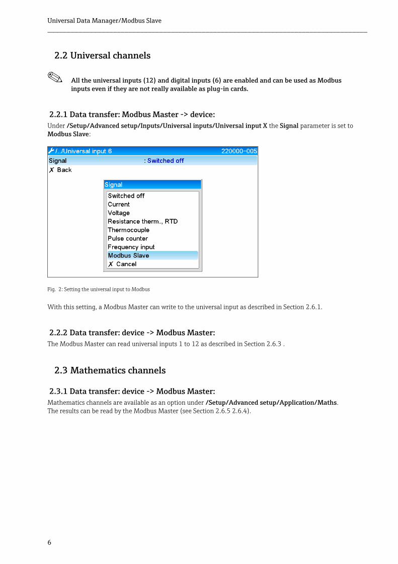
All the universal inputs (12) and digital inputs (6) are enabled and can be used as Modbus inputs even if they are not really available as plug-in cards.
2.2.1 Data transfer: Modbus Master -> device:
Under /Setup/Advanced setup/Inputs/Universal inputs/Universal input X the Signal parameter is set to Modbus Slave:
Fig. 2: Setting the universal input to Modbus
With this setting, a Modbus Master can write to the universal input as described in Section 2.6.1.
2.2.2 Data transfer: device -> Modbus Master:
The Modbus Master can read universal inputs 1 to 12 as described in Section 2.6.3 .
2.3 Mathematics channels
2.3.1 Data transfer: device -> Modbus Master:
Mathematics channels are available as an option under /Setup/Advanced setup/Application/Maths. The results can be read by the Modbus Master (see Section 2.6.5 2.6.4).
Universal Data Manager/Modbus Slave ___________________________________________________________________________________
7
2.4 Digital channels
2.4.1 Data transfer: Modbus Master -> device:
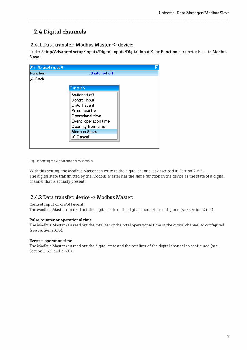
Under Setup/Advanced setup/Inputs/Digital inputs/Digital input X the Function parameter is set to Modbus Slave:
With this setting, the Modbus Master can write to the digital channel as described in Section 2.6.2. The digital state transmitted by the Modbus Master has the same function in the device as the state of a digital channel that is actually present.
2.4.2 Data transfer: device -> Modbus Master:
Control input or on/off event The Modbus Master can read out the digital state of the digital channel so configured (see Section 2.6.5). Pulse counter or operational time The Modbus Master can read out the totalizer or the total operational time of the digital channel so configured (see Section 2.6.6). Event + operation time The Modbus Master can read out the digital state and the totalizer of the digital channel so configured (see Section 2.6.5 and 2.6.6).
Fig. 3: Setting the digital channel to Modbus
Universal Data Manager/Modbus Slave ___________________________________________________________________________________
8
2.5 General information Functions 03: Read Holding Register and 16: Write Multiple Register are supported. The following values can be transmitted from the Modbus Master to the device: - Analog values (instantaneous values) - Digital states The following values can be transmitted from the device to the Modbus Master: - Analog values (instantaneous values) - Integrated analog values (totalizer) - Math channels (result: state, instantaneous value, operating time, totalizer) - Integrated math channels (totalizer) - Digital states - Pulse counter (totalizer) - Operational times - Relay states
Universal Data Manager/Modbus Slave ___________________________________________________________________________________
9
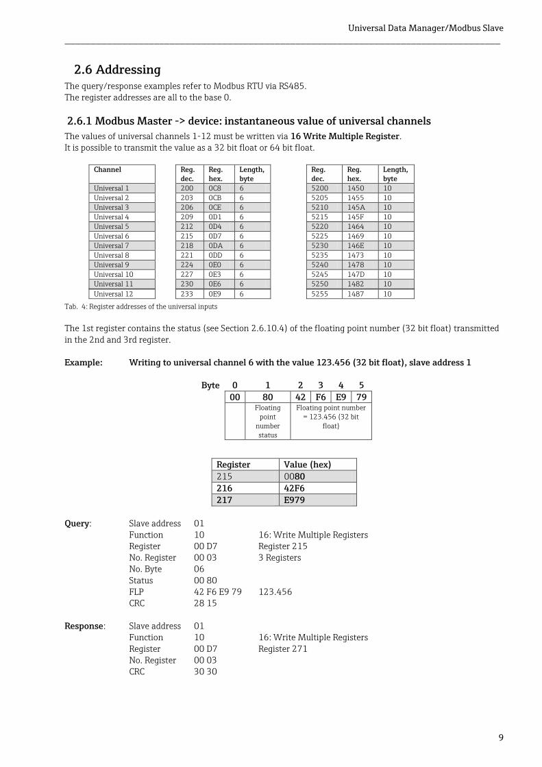
2.6 Addressing The query/response examples refer to Modbus RTU via RS485. The register addresses are all to the base 0.
2.6.1 Modbus Master -> device: instantaneous value of universal channels
The values of universal channels 1-12 must be written via 16 Write Multiple Register. It is possible to transmit the value as a 32 bit float or 64 bit float.
Channel Reg. dec.
Reg. hex.
Length, byte
Reg. dec.
Reg. hex.
Length, byte
Universal 1 200 0C8 6 5200 1450 10
Universal 2 203 0CB 6 5205 1455 10 Universal 3 206 0CE 6 5210 145A 10
Universal 4 209 0D1 6 5215 145F 10 Universal 5 212 0D4 6 5220 1464 10
Universal 6 215 0D7 6 5225 1469 10 Universal 7 218 0DA 6 5230 146E 10
Universal 8 221 0DD 6 5235 1473 10 Universal 9 224 0E0 6 5240 1478 10
Universal 10 227 0E3 6 5245 147D 10 Universal 11 230 0E6 6 5250 1482 10
Universal 12 233 0E9 6 5255 1487 10
The 1st register contains the status (see Section 2.6.10.4) of the floating point number (32 bit float) transmitted in the 2nd and 3rd register. Example: Writing to universal channel 6 with the value 123.456 (32 bit float), slave address 1
Byte 0 1 2 3 4 5
00 80 42 F6 E9 79 Floating
point number status
Floating point number = 123.456 (32 bit
float)
Register Value (hex)
215 0080 216 42F6 217 E979
Query: Slave address 01
Function 10 16: Write Multiple Registers Register 00 D7 Register 215 No. Register 00 03 3 Registers No. Byte 06 Status 00 80 FLP 42 F6 E9 79 123.456 CRC 28 15
Response: Slave address 01
Function 10 16: Write Multiple Registers Register 00 D7 Register 271 No. Register 00 03 CRC 30 30
Tab. 4: Register addresses of the universal inputs
Universal Data Manager/Modbus Slave ___________________________________________________________________________________
10
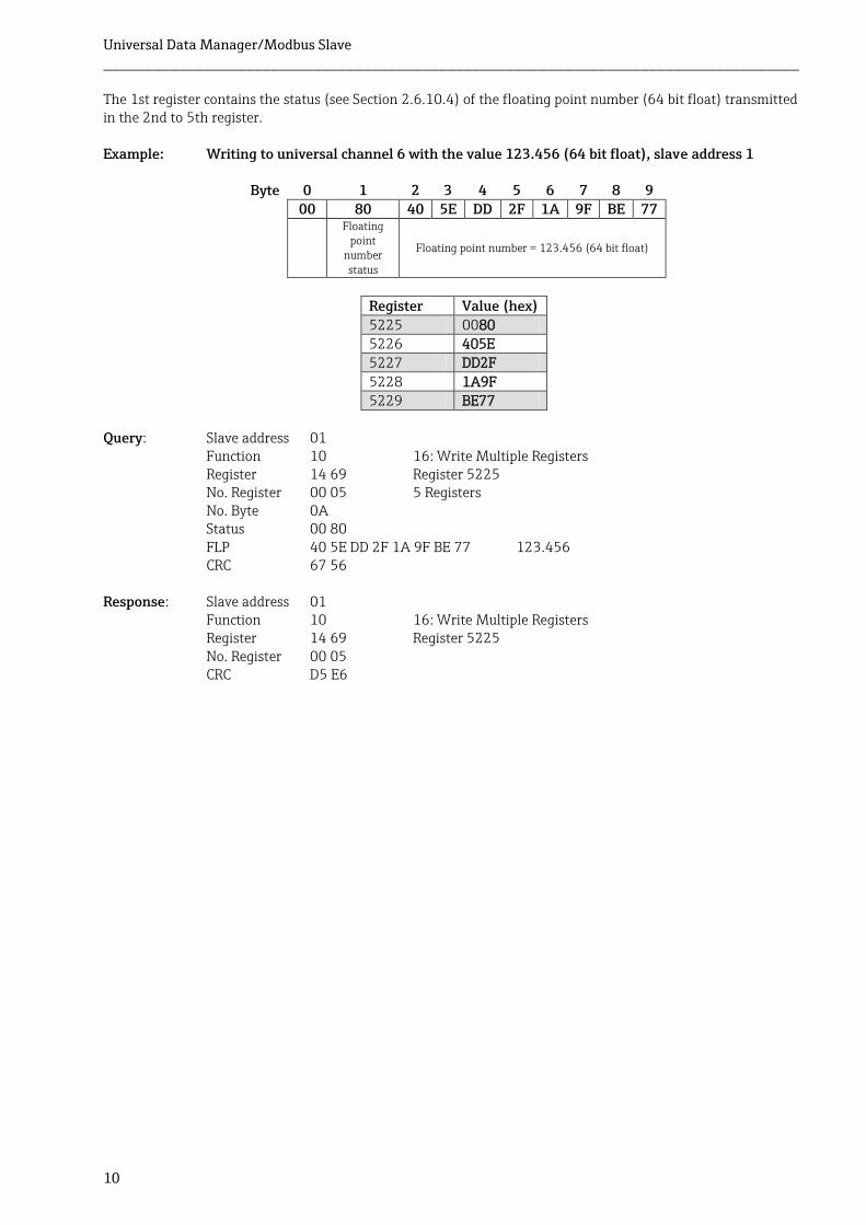
The 1st register contains the status (see Section 2.6.10.4) of the floating point number (64 bit float) transmitted in the 2nd to 5th register. Example: Writing to universal channel 6 with the value 123.456 (64 bit float), slave address 1
Byte 0 1 2 3 4 5 6 7 8 9 00 80 40 5E DD 2F 1A 9F BE 77
Floating point
number status
Floating point number = 123.456 (64 bit float)
Register Value (hex)
5225 0080 5226 405E 5227 DD2F
5228 1A9F 5229 BE77
Query: Slave address 01
Function 10 16: Write Multiple Registers Register 14 69 Register 5225 No. Register 00 05 5 Registers No. Byte 0A Status 00 80 FLP 40 5E DD 2F 1A 9F BE 77 123.456 CRC 67 56
Response: Slave address 01
Function 10 16: Write Multiple Registers Register 14 69 Register 5225 No. Register 00 05 CRC D5 E6
Universal Data Manager/Modbus Slave ___________________________________________________________________________________
11
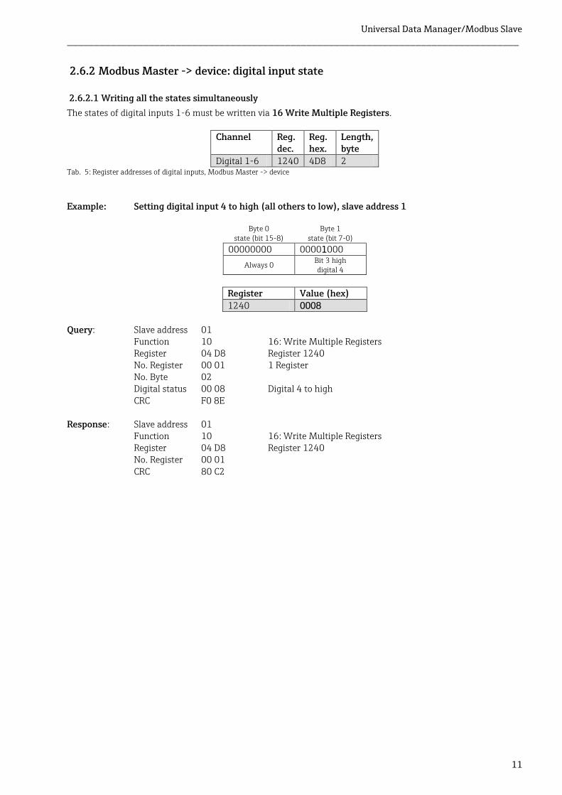
2.6.2 Modbus Master -> device: digital input state
2.6.2.1 Writing all the states simultaneously
The states of digital inputs 1-6 must be written via 16 Write Multiple Registers.
Channel Reg. dec.
Reg. hex.
Length, byte
Digital 1-6 1240 4D8 2
Example: Setting digital input 4 to high (all others to low), slave address 1
Byte 0 state (bit 15-8)
Byte 1 state (bit 7-0)
00000000 00001000
Always 0 Bit 3 high digital 4
Register Value (hex) 1240 0008
Query: Slave address 01
Function 10 16: Write Multiple Registers Register 04 D8 Register 1240 No. Register 00 01 1 Register No. Byte 02 Digital status 00 08 Digital 4 to high CRC F0 8E
Response: Slave address 01
Function 10 16: Write Multiple Registers Register 04 D8 Register 1240 No. Register 00 01 CRC 80 C2
Tab. 5: Register addresses of digital inputs, Modbus Master -> device
Universal Data Manager/Modbus Slave ___________________________________________________________________________________
12
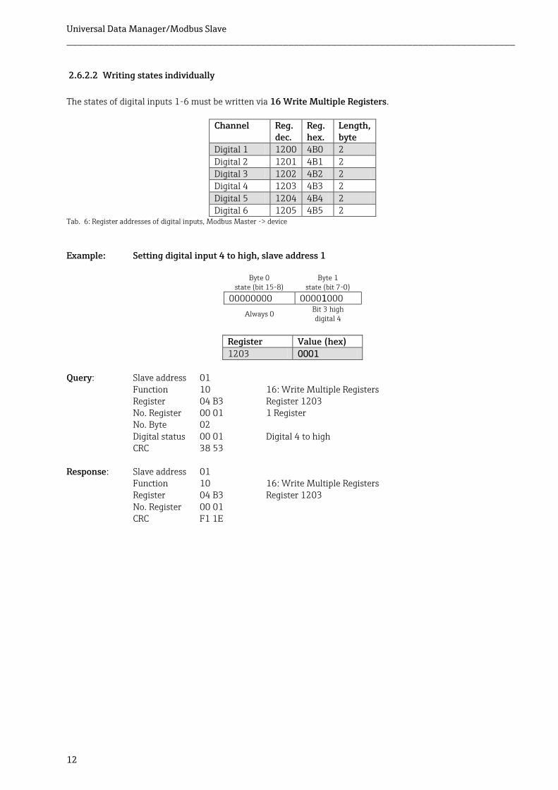
2.6.2.2 Writing states individually
The states of digital inputs 1-6 must be written via 16 Write Multiple Registers.
Channel Reg. dec.
Reg. hex.
Length, byte
Digital 1 1200 4B0 2
Digital 2 1201 4B1 2 Digital 3 1202 4B2 2 Digital 4 1203 4B3 2
Digital 5 1204 4B4 2 Digital 6 1205 4B5 2
Example: Setting digital input 4 to high, slave address 1
Byte 0 state (bit 15-8)
Byte 1 state (bit 7-0)
00000000 00001000
Always 0 Bit 3 high digital 4
Register Value (hex) 1203 0001
Query: Slave address 01
Function 10 16: Write Multiple Registers Register 04 B3 Register 1203 No. Register 00 01 1 Register No. Byte 02 Digital status 00 01 Digital 4 to high CRC 38 53
Response: Slave address 01
Function 10 16: Write Multiple Registers Register 04 B3 Register 1203 No. Register 00 01 CRC F1 1E
Tab. 6: Register addresses of digital inputs, Modbus Master -> device
Universal Data Manager/Modbus Slave ___________________________________________________________________________________
13
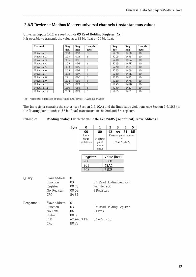
2.6.3 Device -> Modbus Master: universal channels (instantaneous value)
Universal inputs 1-12 are read out via 03 Read Holding Register (4x). It is possible to transmit the value as a 32 bit float or 64 bit float.
Channel Reg. dec.
Reg. hex.
Length, byte
Reg. dec.
Reg. hex.
Length, byte
Universal 1 200 0C8 6 5200 1450 10
Universal 2 203 0CB 6 5205 1455 10 Universal 3 206 0CE 6 5210 145A 10
Universal 4 209 0D1 6 5215 145F 10 Universal 5 212 0D4 6 5220 1464 10
Universal 6 215 0D7 6 5225 1469 10 Universal 7 218 0DA 6 5230 146E 10
Universal 8 221 0DD 6 5235 1473 10 Universal 9 224 0E0 6 5240 1478 10
Universal 10 227 0E3 6 5245 147D 10 Universal 11 230 0E6 6 5250 1482 10
Universal 12 233 0E9 6 5255 1487 10
The 1st register contains the status (see Section 2.6.10.4) and the limit value violations (see Section 2.6.10.3) of the floating point number (32 bit float) transmitted in the 2nd and 3rd register. Example: Reading analog 1 with the value 82.47239685 (32 bit float), slave address 1
Byte 0 1 2 3 4 5
00 80 42 A4 F1 DE Limit
value violations
Floating
point number status
Floating point number =
82.47239685
Register Value (hex) 200 0080
201 42A4 202 F1DE
Query: Slave address 01
Function 03 03: Read Holding Register Register 00 C8 Register 200 No. Register 00 03 3 Registers CRC 84 35
Response: Slave address 01
Function 03 03: Read Holding Register No. Byte 06 6 Bytes Status 00 80 FLP 42 A4 F1 DE 82.47239685 CRC B0 F8
Tab. 7: Register addresses of universal inputs, device -> Modbus Master
Universal Data Manager/Modbus Slave ___________________________________________________________________________________
14
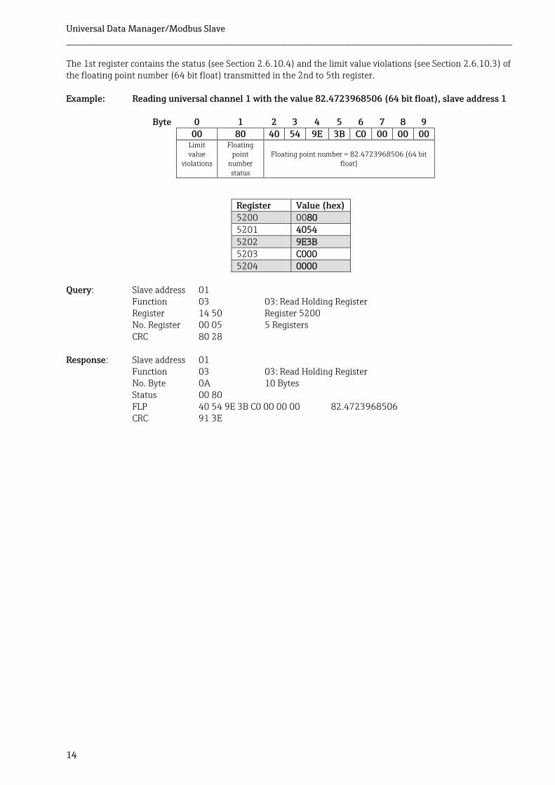
The 1st register contains the status (see Section 2.6.10.4) and the limit value violations (see Section 2.6.10.3) of the floating point number (64 bit float) transmitted in the 2nd to 5th register. Example: Reading universal channel 1 with the value 82.4723968506 (64 bit float), slave address 1
Byte 0 1 2 3 4 5 6 7 8 9 00 80 40 54 9E 3B C0 00 00 00 Limit
value violations
Floating point
number status
Floating point number = 82.4723968506 (64 bit float)
Register Value (hex) 5200 0080 5201 4054
5202 9E3B 5203 C000 5204 0000
Query: Slave address 01
Function 03 03: Read Holding Register Register 14 50 Register 5200 No. Register 00 05 5 Registers CRC 80 28
Response: Slave address 01
Function 03 03: Read Holding Register No. Byte 0A 10 Bytes Status 00 80 FLP 40 54 9E 3B C0 00 00 00 82.4723968506 CRC 91 3E
Universal Data Manager/Modbus Slave ___________________________________________________________________________________
15
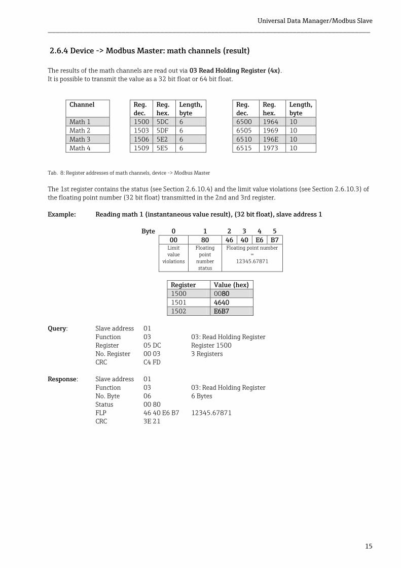
2.6.4 Device -> Modbus Master: math channels (result)
The results of the math channels are read out via 03 Read Holding Register (4x). It is possible to transmit the value as a 32 bit float or 64 bit float.
Channel Reg. dec.
Reg. hex.
Length, byte
Reg. dec.
Reg. hex.
Length, byte
Math 1 1500 5DC 6 6500 1964 10 Math 2 1503 5DF 6 6505 1969 10
Math 3 1506 5E2 6 6510 196E 10 Math 4 1509 5E5 6 6515 1973 10
The 1st register contains the status (see Section 2.6.10.4) and the limit value violations (see Section 2.6.10.3) of the floating point number (32 bit float) transmitted in the 2nd and 3rd register. Example: Reading math 1 (instantaneous value result), (32 bit float), slave address 1
Byte 0 1 2 3 4 5
00 80 46 40 E6 B7 Limit
value violations
Floating point
number status
Floating point number =
12345.67871
Register Value (hex) 1500 0080
1501 4640 1502 E6B7
Query: Slave address 01
Function 03 03: Read Holding Register Register 05 DC Register 1500 No. Register 00 03 3 Registers CRC C4 FD
Response: Slave address 01
Function 03 03: Read Holding Register No. Byte 06 6 Bytes Status 00 80 FLP 46 40 E6 B7 12345.67871 CRC 3E 21
Tab. 8: Register addresses of math channels, device -> Modbus Master
Universal Data Manager/Modbus Slave ___________________________________________________________________________________
16
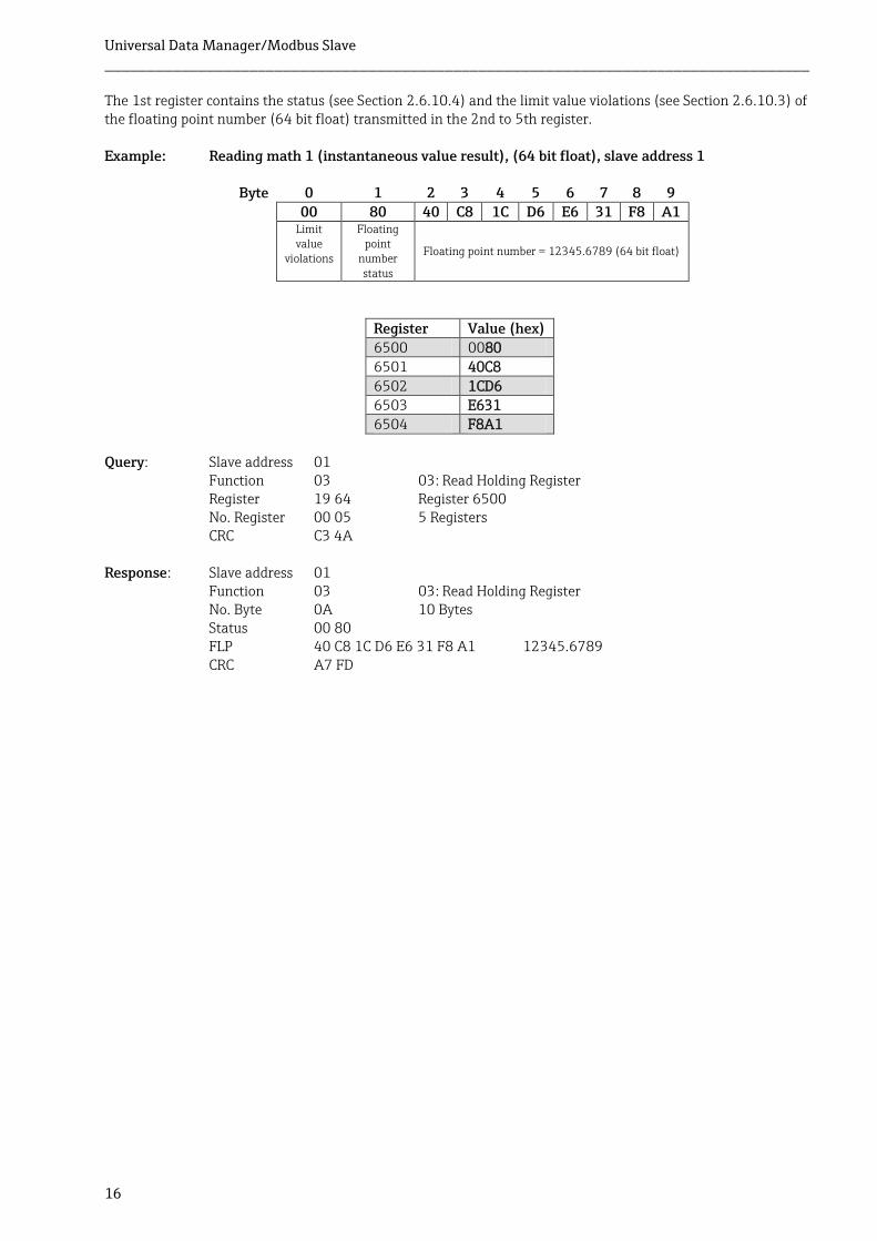
The 1st register contains the status (see Section 2.6.10.4) and the limit value violations (see Section 2.6.10.3) of the floating point number (64 bit float) transmitted in the 2nd to 5th register. Example: Reading math 1 (instantaneous value result), (64 bit float), slave address 1
Byte 0 1 2 3 4 5 6 7 8 9 00 80 40 C8 1C D6 E6 31 F8 A1
Limit value
violations
Floating point
number status
Floating point number = 12345.6789 (64 bit float)
Register Value (hex) 6500 0080 6501 40C8
6502 1CD6 6503 E631 6504 F8A1
Query: Slave address 01
Function 03 03: Read Holding Register Register 19 64 Register 6500 No. Register 00 05 5 Registers CRC C3 4A
Response: Slave address 01
Function 03 03: Read Holding Register No. Byte 0A 10 Bytes Status 00 80 FLP 40 C8 1C D6 E6 31 F8 A1 12345.6789 CRC A7 FD

Universal Data Manager/Modbus Slave ___________________________________________________________________________________
17
Example: Reading math 1-4 (state result), slave address 1 The states of math channels 1-4 are read out via 03 Read Holding Register (4x).
Channel Reg. dec.
Reg. hex.
Length, byte
Math 1-4 1800 708 2
Byte 0
Byte 1 state (bit 5-0)
00000000 00000011
Always 0 Bit 0 and 1 high
Math 1 and 2
Register Value (hex) 1800 0003
Query: Slave address 01
Function 03 3: Read Holding Register Register 07 08 Register 1800 No. Register 00 01 1 Register CRC 04 BC
Response: Slave address 01
Function 03 16: Write Multiple Registers Number 02 2 Bytes States 00 03 Math 1 and 2 state high CRC F8 45
Tab. 9: Register address of states of math channels, device -> Modbus Master
Universal Data Manager/Modbus Slave ___________________________________________________________________________________
18
2.6.5 Device -> Modbus Master: digital channels (state)
2.6.5.1 Reading out all the states simultaneously
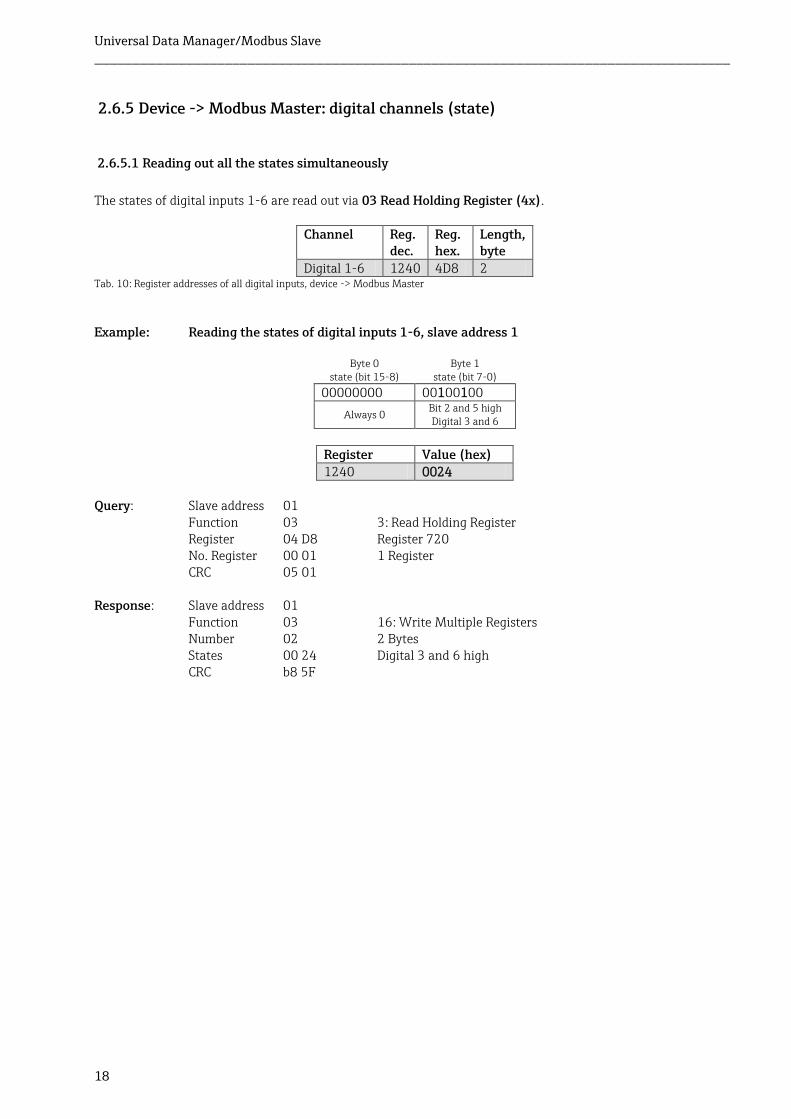
The states of digital inputs 1-6 are read out via 03 Read Holding Register (4x).
Channel Reg. dec.
Reg. hex.
Length, byte
Digital 1-6 1240 4D8 2
Example: Reading the states of digital inputs 1-6, slave address 1
Byte 0 state (bit 15-8)
Byte 1 state (bit 7-0)
00000000 00100100
Always 0 Bit 2 and 5 high Digital 3 and 6
Register Value (hex) 1240 0024
Query: Slave address 01
Function 03 3: Read Holding Register Register 04 D8 Register 720 No. Register 00 01 1 Register CRC 05 01
Response: Slave address 01
Function 03 16: Write Multiple Registers Number 02 2 Bytes States 00 24 Digital 3 and 6 high CRC b8 5F
Tab. 10: Register addresses of all digital inputs, device -> Modbus Master
Universal Data Manager/Modbus Slave ___________________________________________________________________________________
19
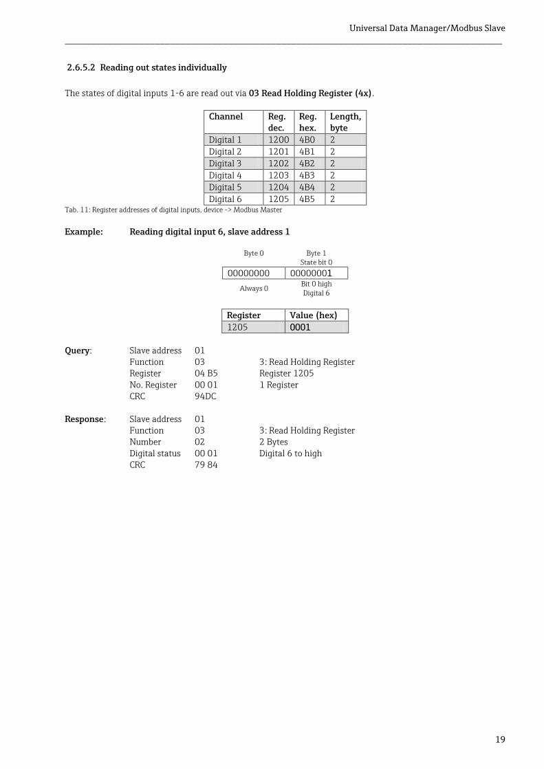
2.6.5.2 Reading out states individually
The states of digital inputs 1-6 are read out via 03 Read Holding Register (4x).
Channel Reg. dec.
Reg. hex.
Length, byte
Digital 1 1200 4B0 2 Digital 2 1201 4B1 2 Digital 3 1202 4B2 2
Digital 4 1203 4B3 2 Digital 5 1204 4B4 2 Digital 6 1205 4B5 2
Example: Reading digital input 6, slave address 1
Byte 0 Byte 1 State bit 0
00000000 00000001
Always 0 Bit 0 high Digital 6
Register Value (hex)
1205 0001 Query: Slave address 01
Function 03 3: Read Holding Register Register 04 B5 Register 1205 No. Register 00 01 1 Register CRC 94DC
Response: Slave address 01
Function 03 3: Read Holding Register Number 02 2 Bytes Digital status 00 01 Digital 6 to high CRC 79 84
Tab. 11: Register addresses of digital inputs, device -> Modbus Master
Universal Data Manager/Modbus Slave ___________________________________________________________________________________
20
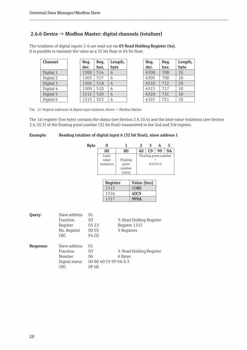
2.6.6 Device -> Modbus Master: digital channels (totalizer)
The totalizers of digital inputs 1-6 are read out via 03 Read Holding Register (4x). It is possible to transmit the value as a 32 bit float or 64 bit float.
Channel Reg. dec.
Reg. hex.
Length, byte
Reg. dec.
Reg. hex.
Length, byte
Digital 1 1300 514 6 6300 708 10
Digital 2 1303 517 6 6305 70D 10 Digital 3 1306 51A 6 6310 712 10 Digital 4 1309 51D 6 6315 717 10
Digital 5 1312 520 6 6320 71C 10 Digital 6 1315 523 6 6325 721 10
The 1st register (low byte) contains the status (see Section 2.6.10.4) and the limit value violations (see Section 2.6.10.3) of the floating point number (32 bit float) transmitted in the 2nd and 3rd register. Example: Reading totalizer of digital input 6 (32 bit float), slave address 1
Byte 0 1 2 3 4 5
00 80 40 C9 99 9A Limit
value violations
Floating
point number status
Floating point number =
65552.0
Register Value (hex) 1315 0080
1316 40C9 1317 999A
Query: Slave address 01
Function 03 3: Read Holding Register Register 05 23 Register 1315 No. Register 00 03 3 Registers CRC F4 CD
Response: Slave address 01
Function 03 3: Read Holding Register Number 06 6 Bytes Digital status 00 80 40 C9 99 9A 6.3 CRC 0F 6E
Tab. 12: Register addresses of digital input totalizers, device -> Modbus Master
Universal Data Manager/Modbus Slave ___________________________________________________________________________________
21
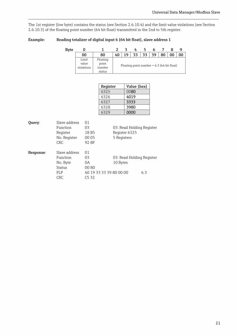
The 1st register (low byte) contains the status (see Section 2.6.10.4) and the limit value violations (see Section 2.6.10.3) of the floating point number (64 bit float) transmitted in the 2nd to 5th register. Example: Reading totalizer of digital input 6 (64 bit float), slave address 1
Byte 0 1 2 3 4 5 6 7 8 9
00 80 40 19 33 33 39 80 00 00 Limit
value violations
Floating point
number status
Floating point number = 6.3 (64 bit float)
Register Value (hex) 6325 0080
6326 4019 6327 3333 6328 3980
6329 0000 Query: Slave address 01
Function 03 03: Read Holding Register Register 18 B5 Register 6325 No. Register 00 05 5 Registers CRC 92 8F
Response: Slave address 01
Function 03 03: Read Holding Register No. Byte 0A 10 Bytes Status 00 80 FLP 40 19 33 33 39 80 00 00 6.3 CRC C5 32

Universal Data Manager/Modbus Slave ___________________________________________________________________________________
22
2.6.7 Device -> Modbus Master: integrated universal channels (totalizer)
The totalizers of universal inputs 1-6 are read out via 03 Read Holding Register (4x). It is possible to transmit the value as a 32 bit float or 64 bit float.
Channel Reg. dec.
Reg. hex.
Length, byte
Reg. dec.
Reg. hex.
Length, byte
Universal1 800 320 6 5800 16A8 10 Universal2 803 323 6 5805 16AD 10 Universal3 806 326 6 5810 16B2 10
Universal4 809 329 6 5815 16B7 10 Universal5 812 32C 6 5820 16BC 10 Universal6 815 32F 6 5825 16C1 10
Universal7 818 332 6 5830 16C6 10 Universal8 821 335 6 5835 16CB 10 Universal9 824 338 6 5840 16D0 10
Universal10 827 33B 6 5845 16D5 10 Universal11 830 33E 6 5850 16DA 10 Universal12 833 341 6 5855 16DF 10
The 1st register contains the status (see Section 2.6.10.4) and the limit value violations (see Section 2.6.10.3) of the floating point number (32 bit float) transmitted in the 2nd and 3rd register. Example: Reading totalizer for universal channel 1 with the value 26557.48633 (32 bit float),
slave address 1
Byte 0 1 2 3 4 5 00 80 46 CF 7A E6 Limit
value violations
Floating point
number status
Floating point number =
26557.48633
Register Value (hex)
800 0080 801 46CF 802 7AE6
Query: Slave address 01
Function 03 03: Read Holding Register Register 03 20 Register 800 No. Register 00 03 3 Registers CRC 04 45
Response: Slave address 01
Function 03 03: Read Holding Register No. Byte 06 6 Bytes Status 00 80 FLP 46 CF 7A E6 3192.73242 CRC E6 FE
Tab. 13: Register addresses of universal input totalizer, device -> Modbus Master
Universal Data Manager/Modbus Slave ___________________________________________________________________________________
23
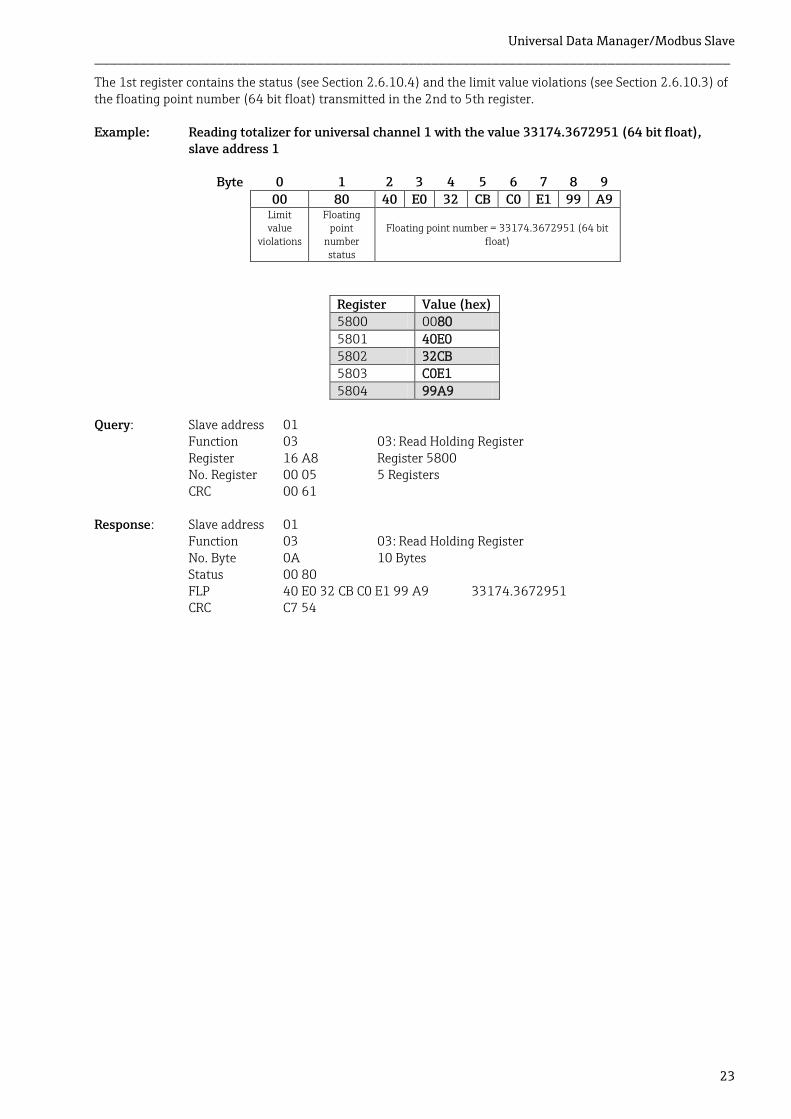
The 1st register contains the status (see Section 2.6.10.4) and the limit value violations (see Section 2.6.10.3) of the floating point number (64 bit float) transmitted in the 2nd to 5th register. Example: Reading totalizer for universal channel 1 with the value 33174.3672951 (64 bit float),
slave address 1
Byte 0 1 2 3 4 5 6 7 8 9
00 80 40 E0 32 CB C0 E1 99 A9 Limit
value violations
Floating point
number status
Floating point number = 33174.3672951 (64 bit float)
Register Value (hex) 5800 0080
5801 40E0 5802 32CB 5803 C0E1
5804 99A9 Query: Slave address 01
Function 03 03: Read Holding Register Register 16 A8 Register 5800 No. Register 00 05 5 Registers CRC 00 61
Response: Slave address 01
Function 03 03: Read Holding Register No. Byte 0A 10 Bytes Status 00 80 FLP 40 E0 32 CB C0 E1 99 A9 33174.3672951 CRC C7 54
Universal Data Manager/Modbus Slave ___________________________________________________________________________________
24
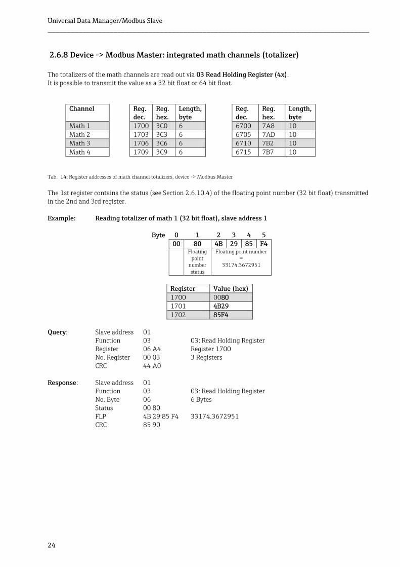
2.6.8 Device -> Modbus Master: integrated math channels (totalizer)
The totalizers of the math channels are read out via 03 Read Holding Register (4x). It is possible to transmit the value as a 32 bit float or 64 bit float.
Channel Reg. dec.
Reg. hex.
Length, byte
Reg. dec.
Reg. hex.
Length, byte
Math 1 1700 3C0 6 6700 7A8 10 Math 2 1703 3C3 6 6705 7AD 10 Math 3 1706 3C6 6 6710 7B2 10
Math 4 1709 3C9 6 6715 7B7 10
The 1st register contains the status (see Section 2.6.10.4) of the floating point number (32 bit float) transmitted in the 2nd and 3rd register. Example: Reading totalizer of math 1 (32 bit float), slave address 1
Byte 0 1 2 3 4 5 00 80 4B 29 85 F4 Floating
point number status
Floating point number =
33174.3672951
Register Value (hex)
1700 0080 1701 4B29 1702 85F4
Query: Slave address 01
Function 03 03: Read Holding Register Register 06 A4 Register 1700 No. Register 00 03 3 Registers CRC 44 A0
Response: Slave address 01
Function 03 03: Read Holding Register No. Byte 06 6 Bytes Status 00 80 FLP 4B 29 85 F4 33174.3672951 CRC 85 90
Tab. 14: Register addresses of math channel totalizers, device -> Modbus Master
Universal Data Manager/Modbus Slave ___________________________________________________________________________________
25
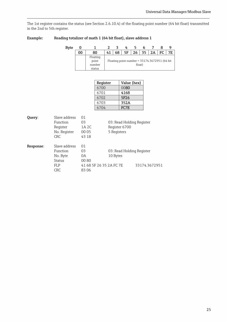
The 1st register contains the status (see Section 2.6.10.4) of the floating point number (64 bit float) transmitted in the 2nd to 5th register. Example: Reading totalizer of math 1 (64 bit float), slave address 1
Byte 0 1 2 3 4 5 6 7 8 9
00 80 41 68 5F 26 35 2A FC 7E
Floating point
number status
Floating point number = 33174.3672951 (64 bit float)
Register Value (hex) 6700 0080
6701 4168 6702 5F26 6703 352A
6704 FC7E Query: Slave address 01
Function 03 03: Read Holding Register Register 1A 2C Register 6700 No. Register 00 05 5 Registers CRC 43 18
Response: Slave address 01
Function 03 03: Read Holding Register No. Byte 0A 10 Bytes Status 00 80 FLP 41 68 5F 26 35 2A FC 7E 33174.3672951 CRC 83 06
Universal Data Manager/Modbus Slave ___________________________________________________________________________________
26
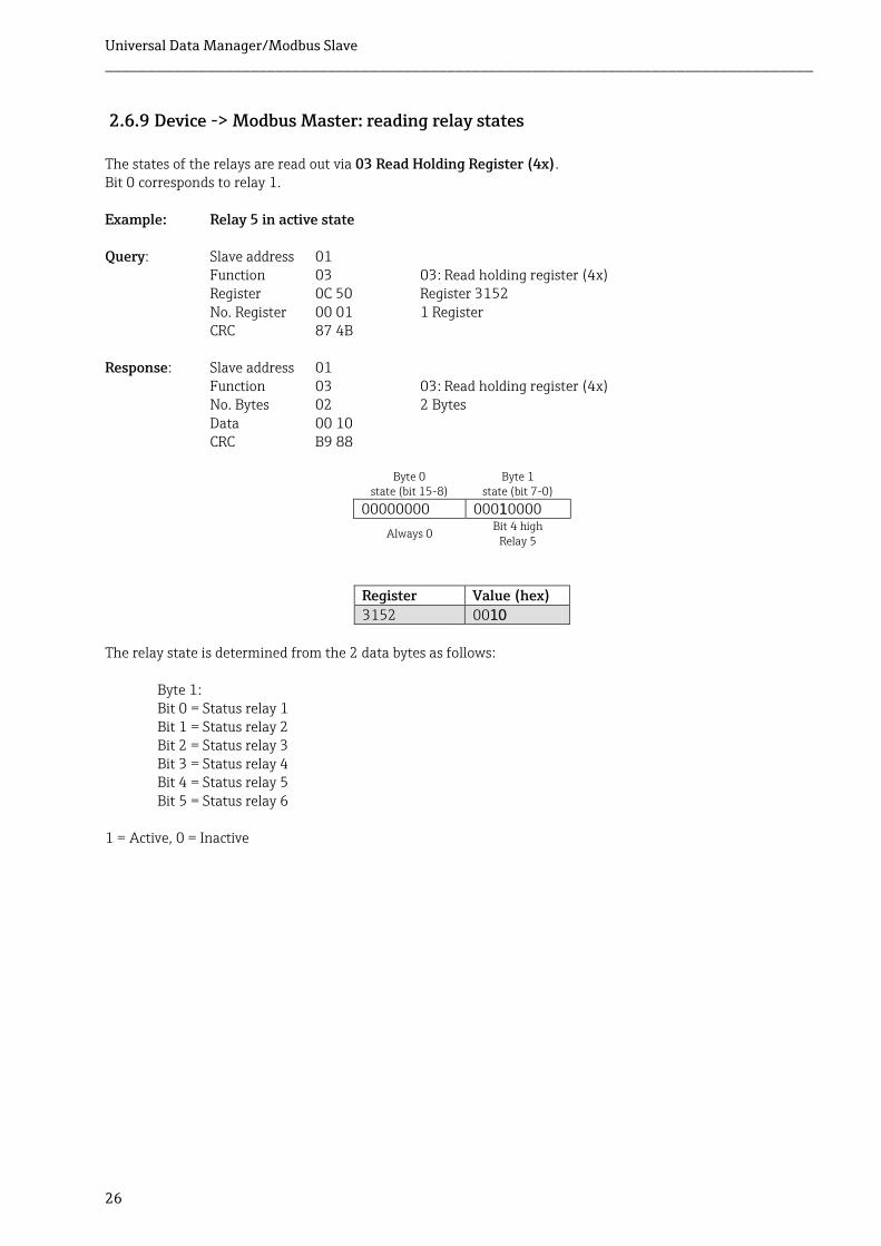
2.6.9 Device -> Modbus Master: reading relay states
The states of the relays are read out via 03 Read Holding Register (4x). Bit 0 corresponds to relay 1. Example: Relay 5 in active state Query: Slave address 01
Function 03 03: Read holding register (4x) Register 0C 50 Register 3152 No. Register 00 01 1 Register CRC 87 4B
Response: Slave address 01 Function 03 03: Read holding register (4x) No. Bytes 02 2 Bytes Data 00 10 CRC B9 88
Byte 0 state (bit 15-8)
Byte 1 state (bit 7-0)
00000000 00010000
Always 0 Bit 4 high
Relay 5
Register Value (hex)
3152 0010 The relay state is determined from the 2 data bytes as follows:
Byte 1: Bit 0 = Status relay 1 Bit 1 = Status relay 2 Bit 2 = Status relay 3 Bit 3 = Status relay 4 Bit 4 = Status relay 5 Bit 5 = Status relay 6
1 = Active, 0 = Inactive
Universal Data Manager/Modbus Slave ___________________________________________________________________________________
27
2.6.10 Structure of the process values
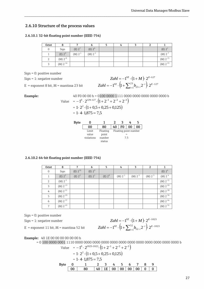
2.6.10.1 32-bit floating point number (IEEE-754)
Octet 8 7 6 5 4 3 2 1
0 Sign (E) 27 (E) 26 (E) 21
1 (E) 20 (M) 2-1 (M) 2-2 (M) 2-7
2 (M) 2-8 (M) 2-15
3 (M) 2-16 (M) 2-23
Sign = 0: positive number
Sign = 1: negative number 127211 EVZ MZahl
E = exponent 8 bit, M = mantissa 23 bit 12723
1 23 2211
E
i
i
i
VZ bZahl
Example: 40 F0 00 00 h = 0100 0000 1111 0000 0000 0000 0000 0000 b
Value = 3211271290 222121
= 125,025,05,0121 2
= 5,7875,141
Byte 0 1 2 3 4 5 00 80 40 F0 00 00 Limit
value violations
Floating point
number status
Floating point number =
7.5
2.6.10.2 64-bit floating point number (IEEE-754)
Octet 8 7 6 5 4 3 2 1
0 Sign (E) 210 (E) 29 (E) 24
1 (E) 23 (E) 22 (E) 21 (E) 20 (M) 2-1 (M) 2-2 (M) 2-3 (M) 2-4
2 (M) 2-5 (M) 2-12
3 (M) 2-13 (M) 2-20
4 (M) 2-21 (M) 2-28
5 (M) 2-29 (M) 2-36
6 (M) 2-37 (M) 2-44
7 (M) 2-45 (M) 2-52
Sign = 0: positive number
Sign = 1: negative number 1023211 EVZ MZahl
E = exponent 11 bit, M = mantissa 52 bit 102352
1 52 2211
E
i
i
i
VZ bZahl
Example: 40 1E 00 00 00 00 00 00 h
= 0 100 0000 0001 1110 0000 0000 0000 0000 0000 0000 0000 0000 0000 0000 0000 0000 b
Value = 321102310250 222121
= 125,025,05,0121 2
= 5,7875,141
Byte 0 1 2 3 4 5 6 7 8 9
00 80 40 1E 00 00 00 00 0 0
Universal Data Manager/Modbus Slave ___________________________________________________________________________________
28
Floating point
number status
Floating point number =7.5
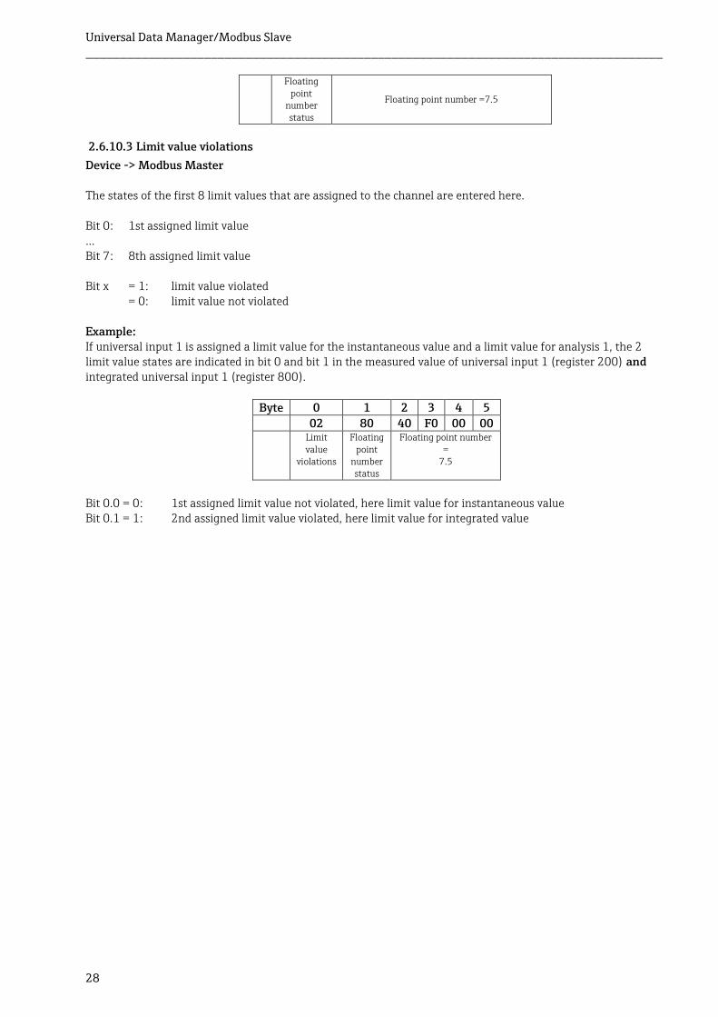
2.6.10.3 Limit value violations
Device -> Modbus Master The states of the first 8 limit values that are assigned to the channel are entered here. Bit 0: 1st assigned limit value … Bit 7: 8th assigned limit value Bit x = 1: limit value violated = 0: limit value not violated Example: If universal input 1 is assigned a limit value for the instantaneous value and a limit value for analysis 1, the 2 limit value states are indicated in bit 0 and bit 1 in the measured value of universal input 1 (register 200) and integrated universal input 1 (register 800).
Byte 0 1 2 3 4 5 02 80 40 F0 00 00 Limit
value violations
Floating point
number status
Floating point number =
7.5
Bit 0.0 = 0: 1st assigned limit value not violated, here limit value for instantaneous value Bit 0.1 = 1: 2nd assigned limit value violated, here limit value for integrated value
Universal Data Manager/Modbus Slave ___________________________________________________________________________________
29
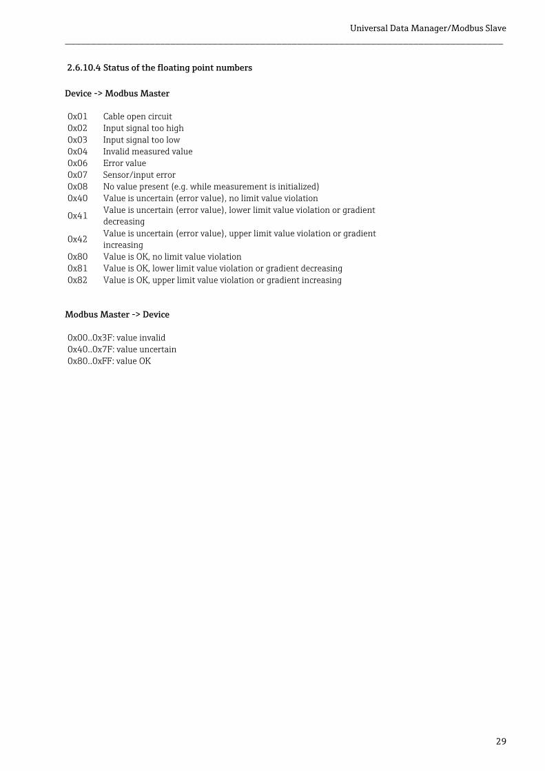
2.6.10.4 Status of the floating point numbers
Device -> Modbus Master 0x01 Cable open circuit 0x02 Input signal too high 0x03 Input signal too low 0x04 Invalid measured value 0x06 Error value 0x07 Sensor/input error 0x08 No value present (e.g. while measurement is initialized) 0x40 Value is uncertain (error value), no limit value violation
0x41 Value is uncertain (error value), lower limit value violation or gradient decreasing
0x42 Value is uncertain (error value), upper limit value violation or gradient increasing
0x80 Value is OK, no limit value violation 0x81 Value is OK, lower limit value violation or gradient decreasing 0x82 Value is OK, upper limit value violation or gradient increasing
Modbus Master -> Device 0x00..0x3F: value invalid 0x40..0x7F: value uncertain 0x80..0xFF: value OK

Universal Data Manager/Modbus Slave ___________________________________________________________________________________
30
3 Overview of registers
The register addresses are all to the base 0, i.e. they correspond to the value that is transmitted in the Modbus protocol. Register Value Format Access 200 Universal 1 Status + 32 Bit Float R/W
203 Universal 2 Status + 32 Bit Float R/W 206 Universal 3 Status + 32 Bit Float R/W
209 Universal 4 Status + 32 Bit Float R/W 212 Universal 5 Status + 32 Bit Float R/W
215 Universal 6 Status + 32 Bit Float R/W 218 Universal 7 Status + 32 Bit Float R/W
221 Universal 8 Status + 32 Bit Float R/W 224 Universal 9 Status + 32 Bit Float R/W
227 Universal 10 Status + 32 Bit Float R/W 230 Universal 11 Status + 32 Bit Float R/W
233 Universal 12 Status + 32 Bit Float R/W 800 Universal 1 totalizer Status + 32 Bit Float R
803 Universal 2 totalizer Status + 32 Bit Float R 806 Universal 3 totalizer Status + 32 Bit Float R
809 Universal 4 totalizer Status + 32 Bit Float R 812 Universal 5 totalizer Status + 32 Bit Float R
815 Universal 6 totalizer Status + 32 Bit Float R 818 Universal 7 totalizer Status + 32 Bit Float R
821 Universal 8 totalizer Status + 32 Bit Float R 824 Universal 9 totalizer Status + 32 Bit Float R
827 Universal 10 totalizer Status + 32 Bit Float R 830 Universal 11 totalizer Status + 32 Bit Float R
833 Universal 12 totalizer Status + 32 Bit Float R 1200 Digital 1 state 2 Byte R/W
1201 Digital 2 state 2 Byte R/W 1202 Digital 3 state 2 Byte R/W
1203 Digital 4 state 2 Byte R/W 1204 Digital 5 state 2 Byte R/W
1210 Digital 6 state 2 Byte R/W 1240 Digital 1-6 states 2 Byte R/W
1300 Digital 1 totalizer Status + 32 Bit Float R 1303 Digital 2 totalizer Status + 32 Bit Float R
1306 Digital 3 totalizer Status + 32 Bit Float R 1309 Digital 4 totalizer Status + 32 Bit Float R
1312 Digital 5 totalizer Status + 32 Bit Float R 1315 Digital 6 totalizer Status + 32 Bit Float R
1700 Math 1 totalizer Status + 32 Bit Float R 1703 Math 2 totalizer Status + 32 Bit Float R
1706 Math 3 totalizer Status + 32 Bit Float R 1709 Math 4 totalizer Status + 32 Bit Float R
5200 Universal 1 Status + 64 Bit Float R/W 5205 Universal 2 Status + 64 Bit Float R/W
5210 Universal 3 Status + 64 Bit Float R/W 5215 Universal 4 Status + 64 Bit Float R/W
5220 Universal 5 Status + 64 Bit Float R/W 5225 Universal 6 Status + 64 Bit Float R/W
5230 Universal 7 Status + 64 Bit Float R/W 5235 Universal 8 Status + 64 Bit Float R/W
5240 Universal 9 Status + 64 Bit Float R/W 5245 Universal 10 Status + 64 Bit Float R/W
5250 Universal 11 Status + 64 Bit Float R/W 5255 Universal 12 Status + 64 Bit Float R/W
5800 Universal 1 totalizer Status + 64 Bit Float R 5805 Universal 2 totalizer Status + 64 Bit Float R
5810 Universal 3 totalizer Status + 64 Bit Float R 5815 Universal 4 totalizer Status + 64 Bit Float R
5820 Universal 5 totalizer Status + 64 Bit Float R 5825 Universal 6 totalizer Status + 64 Bit Float R
5830 Universal 7 totalizer Status + 64 Bit Float R

Universal Data Manager/Modbus Slave ___________________________________________________________________________________
31
5835 Universal 8 totalizer Status + 64 Bit Float R 5840 Universal 9 totalizer Status + 64 Bit Float R
5845 Universal 10 totalizer Status + 64 Bit Float R 5850 Universal 11 totalizer Status + 64 Bit Float R
5855 Universal 12 totalizer Status + 64 Bit Float R 6300 Digital 1 totalizer Status + 64 Bit Float R
6305 Digital 2 totalizer Status + 64 Bit Float R 6310 Digital 3 totalizer Status + 64 Bit Float R
6315 Digital 4 totalizer Status + 64 Bit Float R 6320 Digital 5 totalizer Status + 64 Bit Float R
6325 Digital 6 totalizer Status + 64 Bit Float R 6300 Math 1 totalizer Status + 64 Bit Float R
6305 Math 2 totalizer Status + 64 Bit Float R 6310 Math 3 totalizer Status + 64 Bit Float R
6315 Math 4 totalizer Status + 64 Bit Float R 3152 Relay states 2 Byte R

Universal Data Manager/Modbus Slave ___________________________________________________________________________________
32
4 List of abbreviations/glossary of terms Modbus Master: All instruments such as a PLC, PC-plug-in cards etc. that perform a Modbus Master function.
5 Index Analog channel 6 Baud rate 4 Floating point number 27 Floating point number status 29 Function 4
Inputs 6 LED, status 3 Mathematics channel 6 Outputs 6


![Oracle Identity Manager Oracle FLEXCUBE Universal Banking · Oracle Identity Manager Oracle FLEXCUBE Universal Banking Release 11.3.0 [May] [2011] Oracle Part Number E51536-01.](https://img.dokumen.tips/doc/110x75/5f08fc4e7e708231d424ae18/oracle-identity-manager-oracle-flexcube-universal-banking-oracle-identity-manager.jpg)