Embed Size (px)
Citation preview
TCF SeriesInstallation and Operation Manual

Table of Contents1 GENERAL . . . . . . . . . . . . . . . . . . . . . . . . . . . . . . . . . . . . . . . . . . . . . . . . . . . . . . . . . . . . . . . . . . . . . . . . . . . . . 1
1 .1 PRODUCTSCOVEREDINTHISMANUAL . . . . . . . . . . . . . . . . . . . . . . . . . . . . . . . . . . . . . . . . . . . 11 .2 PRODUCTCHANGES . . . . . . . . . . . . . . . . . . . . . . . . . . . . . . . . . . . . . . . . . . . . . . . . . . . . . . . . . . . 11 .3 WARRANTY . . . . . . . . . . . . . . . . . . . . . . . . . . . . . . . . . . . . . . . . . . . . . . . . . . . . . . . . . . . . . . . . . . . 11 .4 RECEIVING . . . . . . . . . . . . . . . . . . . . . . . . . . . . . . . . . . . . . . . . . . . . . . . . . . . . . . . . . . . . . . . . . . . 11 .5 SAFETYINFORMATION . . . . . . . . . . . . . . . . . . . . . . . . . . . . . . . . . . . . . . . . . . . . . . . . . . . . . . . . . 11 .6 CUSTOMERMODIFICATION . . . . . . . . . . . . . . . . . . . . . . . . . . . . . . . . . . . . . . . . . . . . . . . . . . . . . 2
2 TCFDIMENSIONS . . . . . . . . . . . . . . . . . . . . . . . . . . . . . . . . . . . . . . . . . . . . . . . . . . . . . . . . . . . . . . . . . . . . . . 33 TCFMODELDESIGNATIONCODE . . . . . . . . . . . . . . . . . . . . . . . . . . . . . . . . . . . . . . . . . . . . . . . . . . . . . . . . 54 TCFSPECIFICATIONS . . . . . . . . . . . . . . . . . . . . . . . . . . . . . . . . . . . . . . . . . . . . . . . . . . . . . . . . . . . . . . . . . . 65 TCFRATINGS . . . . . . . . . . . . . . . . . . . . . . . . . . . . . . . . . . . . . . . . . . . . . . . . . . . . . . . . . . . . . . . . . . . . . . . . . 76 INSTALLATION . . . . . . . . . . . . . . . . . . . . . . . . . . . . . . . . . . . . . . . . . . . . . . . . . . . . . . . . . . . . . . . . . . . . . . . . 9
6 .1 INSTALLATIONAFTERALONGPERIODOFSTORAGE . . . . . . . . . . . . . . . . . . . . . . . . . . . . . . 106 .2 EXPLOSIONPROOFAPPLICATIONS . . . . . . . . . . . . . . . . . . . . . . . . . . . . . . . . . . . . . . . . . . . . . 10
7 INPUTACPOWERREQUIREMENTS . . . . . . . . . . . . . . . . . . . . . . . . . . . . . . . . . . . . . . . . . . . . . . . . . . . . . 117 .1 INPUTVOLTAGERATINGS . . . . . . . . . . . . . . . . . . . . . . . . . . . . . . . . . . . . . . . . . . . . . . . . . . . . . 117 .2 INPUTFUSING&DISCONNECTREQUIREMENTS . . . . . . . . . . . . . . . . . . . . . . . . . . . . . . . . . . 127 .3 INPUTWIRESIZEREQUIREMENTS . . . . . . . . . . . . . . . . . . . . . . . . . . . . . . . . . . . . . . . . . . . . . . 137 .4 INSTALLATIONACCORDINGTOEMCREQUIREMENTS . . . . . . . . . . . . . . . . . . . . . . . . . . . . . 13
8 POWERWIRING . . . . . . . . . . . . . . . . . . . . . . . . . . . . . . . . . . . . . . . . . . . . . . . . . . . . . . . . . . . . . . . . . . . . . . 148 .1 WIRINGFORSINGLEPHASEORTHREEPHASEINPUT . . . . . . . . . . . . . . . . . . . . . . . . . . . . . 14
9 TCFPOWERWIRINGDIAGRAM . . . . . . . . . . . . . . . . . . . . . . . . . . . . . . . . . . . . . . . . . . . . . . . . . . . . . . . . . 1510 CONTROLWIRING . . . . . . . . . . . . . . . . . . . . . . . . . . . . . . . . . . . . . . . . . . . . . . . . . . . . . . . . . . . . . . . . . . . . 16
10 .1 CONTROLWIRINGVS .POWERWIRING . . . . . . . . . . . . . . . . . . . . . . . . . . . . . . . . . . . . . . . . . . 1610 .2 TB-2ANDTB-4 . . . . . . . . . . . . . . . . . . . . . . . . . . . . . . . . . . . . . . . . . . . . . . . . . . . . . . . . . . . . . . . 1610 .3 SURGESUPPRESSIONONRELAYS . . . . . . . . . . . . . . . . . . . . . . . . . . . . . . . . . . . . . . . . . . . . . 1610 .4 START/STOPCONTROL . . . . . . . . . . . . . . . . . . . . . . . . . . . . . . . . . . . . . . . . . . . . . . . . . . . . . . . 1610 .5 SPEED/TORQUEREFERENCESIGNALS . . . . . . . . . . . . . . . . . . . . . . . . . . . . . . . . . . . . . . . . . . 1710 .6 SPEEDREFERENCESELECTION . . . . . . . . . . . . . . . . . . . . . . . . . . . . . . . . . . . . . . . . . . . . . . . . 1710 .7 ANALOGOUTPUTSIGNALS . . . . . . . . . . . . . . . . . . . . . . . . . . . . . . . . . . . . . . . . . . . . . . . . . . . . 1910 .8 DRIVESTATUSDIGITALOUTPUTS . . . . . . . . . . . . . . . . . . . . . . . . . . . . . . . . . . . . . . . . . . . . . . 19
11 TCFCONTROLWIRINGDIAGRAMS . . . . . . . . . . . . . . . . . . . . . . . . . . . . . . . . . . . . . . . . . . . . . . . . . . . . . . 2011 .1 TCFTERMINALSTRIP . . . . . . . . . . . . . . . . . . . . . . . . . . . . . . . . . . . . . . . . . . . . . . . . . . . . . . . . . 2011 .2 TWO-WIRESTART/STOPCONTROL . . . . . . . . . . . . . . . . . . . . . . . . . . . . . . . . . . . . . . . . . . . . . 2111 .3 ALTERNATETWO-WIRESTART/STOPCONTROL . . . . . . . . . . . . . . . . . . . . . . . . . . . . . . . . . . 2211 .4 THREE-WIRESTART/STOPCONTROL . . . . . . . . . . . . . . . . . . . . . . . . . . . . . . . . . . . . . . . . . . . . 2311 .5 SPEEDPOTANDPRESETSPEEDCONTROL . . . . . . . . . . . . . . . . . . . . . . . . . . . . . . . . . . . . . . 2411 .6 BIPOLARSPEEDCONTROL(-10to+10VDC) . . . . . . . . . . . . . . . . . . . . . . . . . . . . . . . . . . . . . . 25
12 INITIALPOWERUPANDMOTORROTATION . . . . . . . . . . . . . . . . . . . . . . . . . . . . . . . . . . . . . . . . . . . . . . 2613 PROGRAMMINGTHETCFDRIVE . . . . . . . . . . . . . . . . . . . . . . . . . . . . . . . . . . . . . . . . . . . . . . . . . . . . . . . . 28
13 .1 ELECTRONICPROGRAMMINGMODULE(EPM) . . . . . . . . . . . . . . . . . . . . . . . . . . . . . . . . . . . . 2913 .2 TCFDRIVEPERSONALITY . . . . . . . . . . . . . . . . . . . . . . . . . . . . . . . . . . . . . . . . . . . . . . . . . . . . . 31
14 PARAMETERMENU . . . . . . . . . . . . . . . . . . . . . . . . . . . . . . . . . . . . . . . . . . . . . . . . . . . . . . . . . . . . . . . . . . . 3215 DESCRIPTIONOFPARAMETERS . . . . . . . . . . . . . . . . . . . . . . . . . . . . . . . . . . . . . . . . . . . . . . . . . . . . . . . . 3616 TROUBLESHOOTING . . . . . . . . . . . . . . . . . . . . . . . . . . . . . . . . . . . . . . . . . . . . . . . . . . . . . . . . . . . . . . . . . . 5717 TCFDISPLAYMESSAGES . . . . . . . . . . . . . . . . . . . . . . . . . . . . . . . . . . . . . . . . . . . . . . . . . . . . . . . . . . . . . 59
17 .1 SPEED/TORQUEDISPLAY . . . . . . . . . . . . . . . . . . . . . . . . . . . . . . . . . . . . . . . . . . . . . . . . . . . . . . 5917 .2 CHANGINGTHESPEEDREFERENCESOURCE . . . . . . . . . . . . . . . . . . . . . . . . . . . . . . . . . . . . 6017 .3 STATUSANDWARNINGMESSAGES . . . . . . . . . . . . . . . . . . . . . . . . . . . . . . . . . . . . . . . . . . . . . 61
A APPENDIX-VECTORMODE . . . . . . . . . . . . . . . . . . . . . . . . . . . . . . . . . . . . . . . . . . . . . . . . . . . . . . . . . . . . 62B APPENDIX-INPUTASSERTIONLEVEL . . . . . . . . . . . . . . . . . . . . . . . . . . . . . . . . . . . . . . . . . . . . . . . . . . . 64
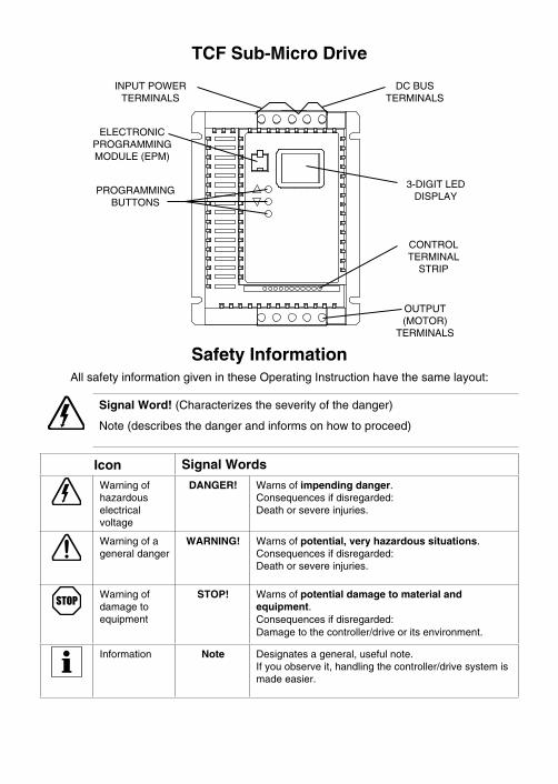
TCF Sub-Micro Drive
INPUTPOWERTERMINALS
OUTPUT(MOTOR)
TERMINALS
CONTROLTERMINAL
STRIP
3-DIGITLEDDISPLAY
ELECTRONICPROGRAMMINGMODULE(EPM)
PROGRAMMINGBUTTONS
DCBUSTERMINALS
Safety InformationAllsafetyinformationgivenintheseOperatingInstructionhavethesamelayout:
Signal Word!(Characterizestheseverityofthedanger)
Note(describesthedangerandinformsonhowtoproceed)
Icon Signal Words
Warningofhazardouselectricalvoltage
DANGER! Warnsofimpending danger .Consequencesifdisregarded:Deathorsevereinjuries .
Warningofageneraldanger
WARNING! Warnsofpotential, very hazardous situations .Consequencesifdisregarded:Deathorsevereinjuries .
Warningofdamagetoequipment
STOP! Warnsofpotential damage to material and equipment .Consequencesifdisregarded:Damagetothecontroller/driveoritsenvironment .
Information Note Designatesageneral,usefulnote .Ifyouobserveit,handlingthecontroller/drivesystemismadeeasier .

1 GENERAL
1 .1 PRODUCTSCOVEREDINTHISMANUAL
ThismanualcoverstheLenzeACTechTCFSeriesVariableFrequencyDrive .
1 .2 PRODUCTCHANGES
LenzeACTechCorporationreservestherighttodiscontinueormakemodificationstothedesignofitsproductswithoutpriornotice,andholdsnoobligationtomakemodificationstoproductssoldpreviously .LenzeACTechalsoholdsnoliabilityforlossesofanykindwhichmayresultfromthisaction .Instructionmanualswiththemostup-to-dateinformationareavailablefordownloadfromtheLenzeACTechwebsite(www .lenzeamericas .com) .
1 .3 WARRANTY
LenzeACTechCorporationwarrantstheTCFSeriesACmotorcontroltobefreeofdefectsinmaterialandworkmanshipforaperiodof24monthsfromthedateofshipmentfromLenzeACTech'sfactory .IfaTCFmotorcontrol,undernormaluse,becomesdefectivewithinthestatedwarrantytimeperiod,contactLenzeACTech'sServiceDepartmentforinstructionsonobtainingawarranty replacementunit .LenzeACTechreserves theright tomake thefinal determination as to the validity of a warranty claim, and sole obligation is to repairorreplaceonlycomponentswhichhavebeenrendereddefectiveduetofaultymaterialorworkmanship .Nowarrantyclaimwillbeacceptedforcomponentswhichhavebeendamagedduetomishandling,improperinstallation,unauthorizedrepairand/oralterationoftheproduct,operationinexcessofdesignspecificationsorothermisuse,orimpropermaintenance .LenzeACTechmakesnowarrantythatitsproductsarecompatiblewithanyotherequipment,ortoanyspecificapplication,towhichtheymaybeappliedandshallnotbeheldliableforanyotherconsequentialdamageorinjuryarisingfromtheuseofitsproducts .Thiswarrantyisinlieuofallotherwarranties,expressedorimplied .Nootherperson,firmorcorporationisauthorizedtoassume,forLenzeACTech,anyotherliabilityinconnectionwiththedemonstrationorsaleofitsproducts .
1 .4 RECEIVING
Inspectallcartonsfordamagewhichmayhaveoccurredduringshipping .Carefullyunpackequipmentandinspectthoroughlyfordamageorshortage .Reportanydamagetocarrierand/orshortagestosupplier .Allmajorcomponentsandconnectionsshouldbeexaminedfordamageandtightness,withspecialattentiongiventoPCboards,plugs,knobsandswitches .
1 .5 SAFETYINFORMATION
GENERALSomepartsofLenzeACTechcontrollerscanbeelectricallyliveandsomesurfacescanbehot .Non-authorizedremovaloftherequiredcover,inappropriateuse,andincorrectinstallationoroperationcreatestheriskofsevereinjurytopersonnelordamagetoequipment .Alloperationsconcerningtransport,installation,andcommissioningaswellasmaintenancemust be carried out by qualified, skilled personnel who are familiar with the installation,assembly,commissioning,andoperationofvariablefrequencydrivesandtheapplicationforwhichitisbeingused .
1
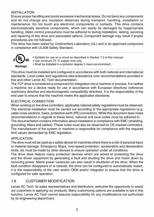
INSTALLATIONEnsureproperhandlingandavoidexcessivemechanicalstress .Donotbendanycomponentsand do not change any insulation distances during transport, handling, installation ormaintenance . Do not touch any electronic components or contacts . This drive containselectrostatically sensitive components, which can easily be damaged by inappropriatehandling .Staticcontrolprecautionsmustbeadheredtoduringinstallation,testing,servicingandrepairingofthisdriveandassociatedoptions .Componentdamagemayresultifproperproceduresarenotfollowed .ThisdrivehasbeentestedbyUnderwritersLaboratory(UL)andisanapprovedcomponentincompliancewithUL508SafetyStandard .
Warnings!
•SuitableforuseonacircuitasdescribedinSection7 .0ofthismanual .•Useminimum75°Ccopperwireonly .•Shallbeinstalledinapollutiondegree2macro-environment .
Thisdrivemustbeinstalledandconfiguredinaccordancewithbothnationalandinternationalstandards .LocalcodesandregulationstakeprecedenceoverrecommendationsprovidedinthisandotherLenzeACTechdocumentation .TheTCFdriveisconsideredacomponentforintegrationintoamachineorprocess .Itisneitheramachinenoradevice ready foruse inaccordancewithEuropeandirectives (referencemachinerydirectiveandelectromagneticcompatibilitydirective) .Itistheresponsibilityoftheendusertoensurethatthemachinemeetstheapplicablestandards .
ELECTRICALCONNECTIONWhenworkingonlivedrivecontrollers,applicablenationalsafetyregulationsmustbeobserved .Theelectricalinstallationmustbecarriedoutaccordingtotheappropriateregulations(e .g .cablecross-sections,fuses,protectiveearth[PE]connection) .Whilethisdocumentdoesmakerecommendationsinregardstotheseitems,nationalandlocalcodesmustbeadheredto .ThedocumentationcontainsinformationaboutinstallationincompliancewithEMC(shielding,grounding,filtersandcables) .ThesenotesmustalsobeobservedforCE-markedcontrollers .ThemanufacturerofthesystemormachineisresponsibleforcompliancewiththerequiredlimitvaluesdemandedbyEMClegislation .
APPLICATIONThedrivemustnotbeusedasasafetydeviceformachineswherethereisariskofpersonalinjuryormaterialdamage .EmergencyStops,over-speedprotection,accelerationanddecelerationlimits,etcmustbemadebyotherdevicestoensureoperationunderallconditions .The drive does feature many protection devices which are aimed at protecting the driveandthedrivenequipmentbygeneratingafaultandshuttingthedriveandmotordownbyremovingpower .Mainspowervariancescanalsoresultinshutdownofthedrive .Whenthefaultconditiondisappearsoriscleared,thedrivecanbeconfiguredtoautomaticallyrestart,it is theresponsibilityof theuserand/orOEMand/or integrator toensurethat thedrive isconfiguredforsafeoperation .
1 .6 CUSTOMERMODIFICATION
LenzeACTech,itssalesrepresentativesanddistributors,welcometheopportunitytoassistourcustomersinapplyingourproducts .Manycustomizingoptionsareavailabletoaidinthisfunction .LenzeACTechcannotassumeresponsibilityforanymodificationsnotauthorizedbyitsengineeringdepartment .
2
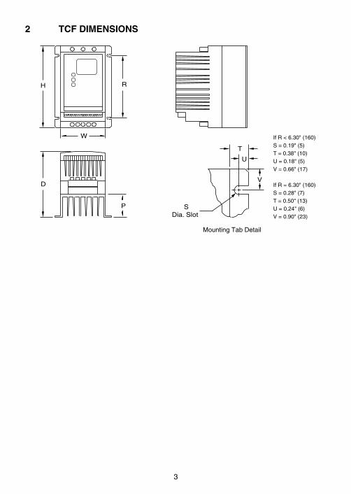
2 TCF DIMENSIONS
MountingTabDetail
IfR<6 .30"(160)S=0 .19"(5)T=0 .38"(10)U=0 .18"(5)V=0 .66"(17)
IfR=6 .30"(160)S=0 .28"(7)T=0 .50"(13)U=0 .24"(6)V=0 .90"(23)
D
H
W
R
P
T
U
V
SDia. Slot
3

HP kWINPUT
VOLTAGEMODEL H W D P R
0 .5 0 .37208/240 TF205Y 5 .75(146) 2 .88(73) 3 .94(100) 0 .80(20) 4 .37(111)
400/480 TF405 5 .75(146) 3 .76(96) 5 .24(133) 1 .90(48) 4 .37(111)
1 0 .75
208/240 TF210Y 5 .75(146) 2 .88(73) 4 .74(120) 1 .60(41) 4 .37(111)
208/240 TF210 5 .75(146) 2 .88(73) 4 .74(120) 1 .60(41) 4 .37(111)
400/480 TF410 5 .75(146) 3 .76(96) 5 .24(133) 1 .90(48) 4 .37(111)
480/590 TF510 5 .75(146) 3 .76(96) 5 .24(133) 1 .90(48) 4 .37(111)
1 .5 1 .1
208/240 TF215Y 5 .75(146) 3 .76(96) 5 .24(133) 1 .90(48) 4 .37(111)
208/240 TF215 5 .75(146) 2 .88(73) 5 .74(146) 2 .60(66) 4 .37(111)
400/480 TF415 5 .75(146) 3 .76(96) 5 .24(133) 1 .90(48) 4 .37(111)
2 1 .5
208/240 TF220Y 5 .75(146) 3 .76(96) 6 .74(171) 3 .40(86) 4 .37(111)
208/240 TF220 5 .75(146) 3 .76(96) 6 .74(171) 3 .40(86) 4 .37(111)
400/480 TF420 5 .75(146) 3 .76(96) 6 .74(171) 3 .40(86) 4 .37(111)
480/590 TF520 5 .75(146) 3 .76(96) 6 .74(171) 3 .40(86) 4 .37(111)
3 2 .2
208/240 TF230Y 5 .75(146) 3 .76(96) 6 .74(171) 3 .40(86) 3 .25(83)
208/240 TF230 5 .75(146) 3 .76(96) 6 .74(171) 3 .40(86) 3 .25(83)
400/480 TF430 5 .75(146) 3 .76(96) 6 .74(171) 3 .40(86) 3 .25(83)
480/590 TF530 5 .75(146) 3 .76(96) 6 .74(171) 3 .40(86) 3 .25(83)
5 4 .0
208/240 TF250 5 .75(146) 3 .76(96) 6 .74(171) 3 .40(86) 3 .25(83)
400/480 TF450 5 .75(146) 3 .76(96) 6 .74(171) 3 .40(86) 3 .25(83)
480/590 TF550 5 .75(146) 3 .76(96) 6 .74(171) 3 .40(86) 3 .25(83)
7 .5 5 .5
208/240 TF275 7 .75(197) 5 .02(128) 7 .18(182) 3 .40(86) 4 .81(122)
400/480 TF475 7 .75(197) 5 .02(128) 7 .18(182) 3 .40(86) 4 .81(122)
480/590 TF575 7 .75(197) 5 .02(128) 7 .18(182) 3 .40(86) 4 .81(122)
10 7 .5
208/240 TF2100 7 .75(197) 5 .02(128) 7 .18(182) 3 .40(86) 4 .81(122)
400/480 TF4100 7 .75(197) 5 .02(128) 7 .18(182) 3 .40(86) 4 .81(122)
480/590 TF5100 7 .75(197) 5 .02(128) 7 .18(182) 3 .40(86) 4 .81(122)
4
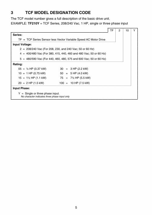
3 TCF MODEL DESIGNATION CODETheTCFmodelnumbergivesafulldescriptionofthebasicdriveunit .
EXAMPLE:TF210Y=TCFSeries,208/240Vac,1HP,singleorthreephaseinput
TF 2 10 Y
Series:
TF=TCFSeriesSensorlessVectorVariableSpeedACMotorDrive
Input Voltage:
2=208/240Vac(For208,230,and240Vac;50or60Hz)
4=400/480Vac(For380,415,440,460and480Vac;50or60Hz)
5=480/590Vac(For440,460,480,575and600Vac;50or60Hz)
Rating:
05=½HP(0 .37kW) 30 = 3HP(2 .2kW)
10=1HP(0 .75kW) 50 = 5HP(4 .0kW)
15=1½HP(1 .1kW) 75 = 7½HP(5 .5kW)
20=2HP(1 .5kW) 100 = 10HP(7 .5kW)
Input Phase:
Y=Singleorthreephaseinput . No character indicates three phase input only
5
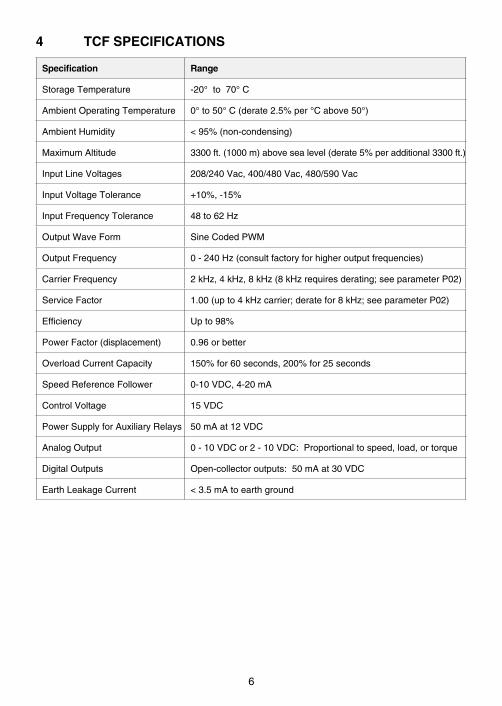
4 TCF SPECIFICATIONS
Specification Range
StorageTemperature -20°to70°C
AmbientOperatingTemperature 0°to50°C(derate2 .5%per°Cabove50°)
AmbientHumidity <95%(non-condensing)
MaximumAltitude 3300ft .(1000m)abovesealevel(derate5%peradditional3300ft .)
InputLineVoltages 208/240Vac,400/480Vac,480/590Vac
InputVoltageTolerance +10%,-15%
InputFrequencyTolerance 48to62Hz
OutputWaveForm SineCodedPWM
OutputFrequency 0-240Hz(consultfactoryforhigheroutputfrequencies)
CarrierFrequency 2kHz,4kHz,8kHz(8kHzrequiresderating;seeparameterP02)
ServiceFactor 1 .00(upto4kHzcarrier;deratefor8kHz;seeparameterP02)
Efficiency Upto98%
PowerFactor(displacement) 0 .96orbetter
OverloadCurrentCapacity 150%for60seconds,200%for25seconds
SpeedReferenceFollower 0-10VDC,4-20mA
ControlVoltage 15VDC
PowerSupplyforAuxiliaryRelays 50mAat12VDC
AnalogOutput 0-10VDCor2-10VDC:Proportionaltospeed,load,ortorque
DigitalOutputs Open-collectoroutputs:50mAat30VDC
EarthLeakageCurrent <3 .5mAtoearthground
6
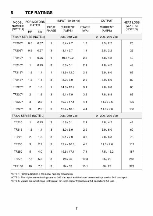
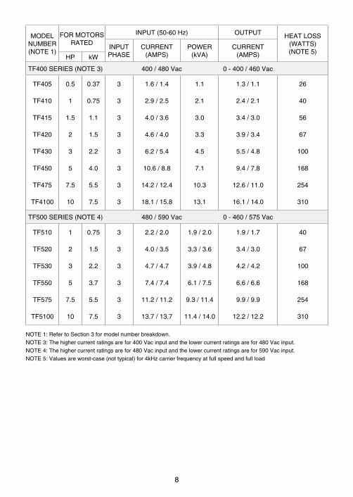
5 TCF RATINGS
MODELNUMBER(NOTE1)
FORMOTORSRATED
INPUT(50-60Hz) OUTPUTHEATLOSS
(WATTS)(NOTE5)
INPUTPHASE
CURRENT(AMPS)
POWER(kVA)
CURRENT(AMPS)HP kW
TF200YSERIES(NOTE2) 208/240Vac 0-200/230Vac
TF205Y 0 .5 0 .37 1 5 .4/4 .7 1 .2 2 .5/2 .2 26
TF205Y 0 .5 0 .37 3 3 .1/2 .7 1 .1 2 .5/2 .2 26
TF210Y 1 0 .75 1 10 .6/9 .2 2 .2 4 .8/4 .2 49
TF210Y 1 0 .75 3 5 .8/5 .1 2 .1 4 .8/4 .2 49
TF215Y 1 .5 1 .1 1 13 .9/12 .0 2 .9 6 .9/6 .0 82
TF215Y 1 .5 1 .1 3 8 .0/6 .9 2 .9 6 .9/6 .0 82
TF220Y 2 1 .5 1 14 .8/12 .9 3 .1 7 .8/6 .8 86
TF220Y 2 1 .5 3 9 .1/7 .9 3 .2 7 .8/6 .8 86
TF230Y 3 2 .2 1 19 .7/17 .1 4 .1 11 .0/9 .6 130
TF230Y 3 2 .2 3 12 .4/10 .8 4 .4 11 .0/9 .6 130
TF200SERIES(NOTE2) 208/240Vac 0-200/230Vac
TF210 1 0 .75 3 5 .8/5 .1 2 .1 4 .8/4 .2 41
TF215 1 .5 1 .1 3 8 .0/6 .9 2 .9 6 .9/6 .0 69
TF220 2 1 .5 3 9 .1/7 .9 3 .3 7 .8/6 .8 78
TF230 3 2 .2 3 12 .4/10 .8 4 .5 11 .0/9 .6 117
TF250 5 4 .0 3 19 .6/17 .1 7 .1 17 .5/15 .2 187
TF275 7 .5 5 .5 3 28/25 10 .3 25/22 286
TF2100 10 7 .5 3 34/32 13 .1 30/28 379
NOTE1:RefertoSection3formodelnumberbreakdown .NOTE2:Thehighercurrentratingsarefor208Vacinputandthelowercurrentratingsarefor240Vacinput .NOTE5:Valuesareworst-case(nottypical)for4kHzcarrierfrequencyatfullspeedandfullload .
7
MODELNUMBER(NOTE1)
FORMOTORSRATED
INPUT(50-60Hz) OUTPUT HEATLOSS(WATTS)(NOTE5)
INPUTPHASE
CURRENT(AMPS)
POWER(kVA)
CURRENT(AMPS)HP kW
TF400SERIES(NOTE3) 400/480Vac 0-400/460Vac
TF405 0 .5 0 .37 3 1 .6/1 .4 1 .1 1 .3/1 .1 26
TF410 1 0 .75 3 2 .9/2 .5 2 .1 2 .4/2 .1 40
TF415 1 .5 1 .1 3 4 .0/3 .6 3 .0 3 .4/3 .0 56
TF420 2 1 .5 3 4 .6/4 .0 3 .3 3 .9/3 .4 67
TF430 3 2 .2 3 6 .2/5 .4 4 .5 5 .5/4 .8 100
TF450 5 4 .0 3 10 .6/8 .8 7 .1 9 .4/7 .8 168
TF475 7 .5 5 .5 3 14 .2/12 .4 10 .3 12 .6/11 .0 254
TF4100 10 7 .5 3 18 .1/15 .8 13 .1 16 .1/14 .0 310
TF500SERIES(NOTE4) 480/590Vac 0-460/575Vac
TF510 1 0 .75 3 2 .2/2 .0 1 .9/2 .0 1 .9/1 .7 40
TF520 2 1 .5 3 4 .0/3 .5 3 .3/3 .6 3 .4/3 .0 67
TF530 3 2 .2 3 4 .7/4 .7 3 .9/4 .8 4 .2/4 .2 100
TF550 5 3 .7 3 7 .4/7 .4 6 .1/7 .5 6 .6/6 .6 168
TF575 7 .5 5 .5 3 11 .2/11 .2 9 .3/11 .4 9 .9/9 .9 254
TF5100 10 7 .5 3 13 .7/13 .7 11 .4/14 .0 12 .2/12 .2 310
NOTE1:RefertoSection3formodelnumberbreakdown .NOTE3:Thehighercurrentratingsarefor400Vacinputandthelowercurrentratingsarefor480Vacinput .NOTE4:Thehighercurrentratingsarefor480Vacinputandthelowercurrentratingsarefor590Vacinput .NOTE5:Valuesareworst-case(nottypical)for4kHzcarrierfrequencyatfullspeedandfullload
8
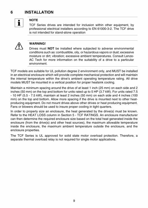
6 INSTALLATION
NOTE
TCF Series drives are intended for inclusion within other equipment, byprofessionalelectricalinstallersaccordingtoEN61000-3-2 .TheTCFdriveisnotintendedforstand-aloneoperation
WARNING!
Drives must NOT be installed where subjected to adverse environmentalconditionssuchas:combustible,oily,orhazardousvaporsordust;excessivemoistureordirt;vibration;excessiveambienttemperatures .ConsultLenze-AC Tech for more information on the suitability of a drive to a particularenvironment .
TCFmodelsaresuitableforULpollutiondegree2environmentonly,andMUSTbeinstalledinanelectricalenclosurewhichwillprovidecompletemechanicalprotectionandwillmaintainthe internal temperaturewithin thedrive’sambientoperating temperature rating .AlldrivemodelsMUSTbemountedinaverticalpositionforproperheatsinkcooling .
Maintainaminimumspacingaroundthedriveofatleast1inch(25mm)oneachsideand2inches(50mm)onthetopandbottomforunitsratedupto5HP(3 .7kW) .Forunitsrated7 .5-10HP(5 .5-7 .5kW),maintainatleast2inches(50mm)oneachsideand4inches(100mm)onthetopandbottom .Allowmorespacingifthedriveismountednexttootherheat-producingequipment .Donotmountdrivesaboveotherdrivesorheatproducingequipment .Fansorblowersshouldbeusedtoinsurepropercoolingintightquarters .
Inordertoproperlysizeanenclosure,theheatgeneratedbythedrive(s)mustbeknown .RefertotheHEATLOSScolumninSection5-TCFRATINGS .Anenclosuremanufacturercanthendeterminetherequiredenclosuresizebasedonthetotalheatgeneratedinsidetheenclosure(fromthedrive(s)andotherheatsources),themaximumallowabletemperatureinside the enclosure, the maximum ambient temperature outside the enclosure, and theenclosureproperties .
The TCF Series is UL approved for solid state motor overload protection . Therefore, aseparatethermaloverloadrelayisnotrequiredforsinglemotorapplications .
9

6 .1 INSTALLATIONAFTERALONGPERIODOFSTORAGE
STOP!
SeveredamagetothedrivecanresultifitisoperatedafteralongperiodofstorageorinactivitywithoutreformingtheDCbuscapacitors!
Ifinputpowerhasnotbeenappliedtothedriveforaperiodoftimeexceedingthreeyears(duetostorage,etc),theelectrolyticDCbuscapacitorswithinthedrivecanchangeinternally,resultinginexcessiveleakagecurrent .Thiscanresultinprematurefailureofthecapacitorsifthedriveisoperatedaftersuchalongperiodofinactivityorstorage .
Inordertoreformthecapacitorsandpreparethedriveforoperationafteralongperiodofinactivity,applyinputpowertothedrivefor8hourspriortoactuallyoperatingthemotor .
6 .2 EXPLOSIONPROOFAPPLICATIONS
Explosionproofmotorsthatarenotratedforinverteruselosetheircertificationwhenusedforvariablespeed .Duetothemanyareasofliabilitythatmaybeencounteredwhendealingwiththeseapplications,thefollowingstatementofpolicyapplies:
“Lenze AC Tech inverter products are sold with no warranty of fitness for a particular purpose or warranty of suitability for use with explosion proof motors. Lenze AC Tech accepts no responsibility for any direct, incidental or consequential loss, cost, or damage that may arise through the use of its AC inverter products in these applications. The purchaser expressly agrees to assume all risk of any loss, cost, or damage that may arise from such application."
10

7 INPUT AC POWER REQUIREMENTS
DANGER!
Hazard of electrical shock! Capacitors retain charge after they've beenremoved . Disconnect incoming power and wait until the voltage betweenterminalsB+andB-is0VDCbeforeservicingthedrive .
Theinputvoltagemustmatchthenameplatevoltageratingofthedrive .Voltagefluctuationmustnotvarybygreaterthan10%overvoltageor15%undervoltage .
NOTE
Driveswithdual inputvoltageratingsmustbeprogrammedforthepropersupply voltage (refer to Parameter 01 - LINE VOLTAGE SELECTION inSection15-DESCRIPTIONOFPARAMETERS) .
Thedrive issuitable foruseonacircuit capableofdeliveringnotmore than5,000RMSsymmetricalamperesat5HP(4 .0kW)andbelow,and18,000RMSsymmetricalamperesat7 .5-10HP(5 .5-7 .5kW),atthedrive’sratedvoltage .
IfthekVAratingoftheACsupplytransformerisgreaterthan10timestheinputkVAratingofthedrive(s),anisolationtransformeror2-3%inputlinereactormustbeaddedtothelinesideofthedrive(s) .
Threephasevoltageimbalancemustbelessthan2 .0%phasetophase .Excessivephasetophaseimbalancecancauseseveredamagetothedrive’spowercomponents .
Motorvoltageshouldmatchlinevoltageinnormalapplications .Thedrive’smaximumoutputvoltagewillequaltheinputvoltage .Useextremecautionwhenusingamotorwithavoltageratingwhichisdifferentfromtheinputlinevoltage .
7 .1 INPUTVOLTAGERATINGS
TF200 Seriesdrivesareratedfor208/240Vac,threephase,50-60Hzinput .Thedrivewillfunctionwithinputvoltagesof208to240Vac(+10%,-15%)at48to62Hz .
TF200Y Seriesdrivesareratedfor208/240Vac,singleorthreephase,50-60Hzinput .Thedrivewillfunctionwithinputvoltageof208to240Vac(+10%,-15%)at48to62Hz .
TF400 Seriesdrivesareratedfor400/480Vacthreephase,50-60Hzinput .Thedrivewillfunctionwithinputvoltagesof400to480Vac(+10%,-15%)at48to62Hz .
TF500 Seriesdrivesareratedfor480/590Vac,threephase,50-60Hzinput,andwillfunctionwithinputvoltagesof480to590Vac(+10%,-15%)at48to62Hz .
NOTE
Parameter 01 - LINE VOLTAGE SELECTION must be programmedaccordingtotheappliedinputvoltage .RefertoSection15-DESCRIPTIONOFPARAMETERS .
11

7 .2 INPUTFUSING&DISCONNECTREQUIREMENTS
AcircuitbreakeroradisconnectswitchwithfusesmustbeprovidedinaccordancewiththeNationalElectricCode(NEC)andall localcodes .Refer to the following tables forproperfuse/circuitbreakerratingsandwiresizes .
INPUT FUSE & CIRCUIT BREAKER RATINGS
208/240Vac,1phase 208/240Vac,3phase 400/480Vac,3phase 480/590Vac,3phase
MODEL RATING MODEL RATING MODEL RATING MODEL RATING
TF205Y 10A TF205Y 10A TF405 10A
TF210Y 15A TF210(Y) 10A TF410 10A TF510 10A
TF215Y 20A TF215(Y) 12/10A TF415 10A
TF220Y 25/20A TF220(Y) 15/12A TF420 10A TF520 10A
TF230Y 30/25A TF230(Y) 20/15A TF430 10A TF530 10A
TF250 30/25A TF450 15A TF550 12A
TF275 45/40A TF475 20A TF575 20A
TF2100 50/50A TF4100 30/25A TF5100 20A
NOTE
• Applicable national and local electrical codes take precedence overrecommendationsinthesetables .
• UseULClassCCfast-acting,current limiting type fuses .Select fuseswith low I2T values, rated at 200,000 AIC . Recommended fuses areBussmanKTK-R,JJN,andJJS .Similarfuseswithequivalentratingsbyothermanufacturersmayalsobeacceptable .
WARNING!
This product can cause a DC current in the protective conductor . Wherearesidualcurrentdevice(RCD) isused forprotection incaseofdirectorindirectcontact,onlyanRCDofTypeB isallowedon thesupplysideofthisproduct .Otherwise,anotherprotectivemeasureshallbeapplied,suchasseparation from theenvironmentbydoubleor reinforced insulation,orisolationfromthesupplysystembyatransformer .
ObservethefollowingwhenusingRCDs:
1 . OnlyinstalltheRCDbetweenthesupplymainsanddrivecontroller .2 . TheRCDcanbeactivatedby:
• capacitiveleakagecurrentsbetweenthecablescreensduringoperation(especiallywithlong,screenedmotorcables)
• connectingseveraldrivestothemainsatthesametime• additionalRFIfilters
12

7 .3 INPUTWIRESIZEREQUIREMENTS
INPUT WIRE SIZE REQUIREMENTS
208/240Vac,1phase 208/240Vac,3phase 400/480Vac,3phase 480/590Vac,3phase
MODEL AWG mm2 MODEL AWG mm2 MODEL AWG mm2 MODEL AWG mm2
TF205Y 14 1 .5 TF205Y 14 1 .5 TF405 14 1 .5
TF210Y 14 1 .5 TF210(Y) 14 1 .5 TF410 14 1 .5 TF510 14 1 .5
TF215Y 12 2 .5 TF215(Y) 14 1 .5 TF415 14 1 .5
TF220Y 12 2 .5 TF220(Y) 14 1 .5 TF420 14 1 .5 TF520 14 1 .5
TF230Y 10 4 .0 TF230(Y) 12 2 .5 TF430 14 1 .5 TF530 14 1 .5
TF250 10 4 .0 TF450 14 1 .5 TF550 14 1 .5
TF275 8 6 .0 TF475 12 2 .5 TF575 14 1 .5
TF2100 8 10 TF4100 10 4 .0 TF5100 12 2 .5
7 .4 INSTALLATIONACCORDINGTOEMCREQUIREMENTS
ThisdrivecanbeinstalledtomeettheEuropeanstandardsforElectromagneticCompatibility(EMC)requirements .Theserequirementsgovernthepermissibleelectromagneticemissionsandimmunity,bothradiatedandconducted,ofadrivesystem .
The EMC requirements apply to the final installation in its entirety, not to the individualcomponents used . Because every installation is different, the recommended installationshould follow these guidelines as a minimum . Additional equipment (such as ferrite coreabsorbers on power conductors) or alternative wiring practices may be required to meetconformanceinsomeinstallations .
Filter:Theinputtothedrive(orgroupofdrives)mustincludeafiltertoreducetheelectricalnoisereflectedbacktotheACLine .TomeettheindustrialstandardssetbytheEU,EN61800-3forconductedemissionsandEN55011forradiatedemissionstoclassAcompliance,thedrivemustbeinstalledwithanappropriatefilterandamaximummotorcablelengthof10m .
EMCCompliancewithEN61800-3/A11
SM01 1
B
C
DA
E
Installation:Shieldedcablemustbeusedforallcontrolandpowercablesandexposedwiringmustbekeptasshortaspossible .
AScreenclamps
BControlcable
CLow-capacitancemotorcable
(core/core<75pF/m,core/screen<150pF/m)
DElectricallyconductivemountingplate
EFilter
13
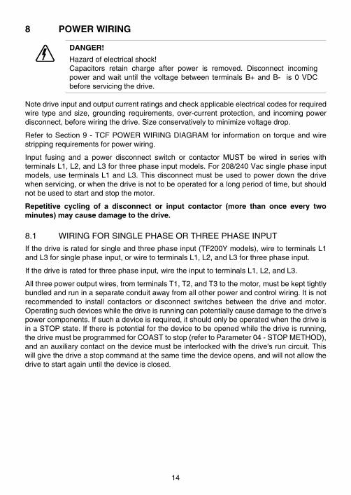
8 POWER WIRING
DANGER!
Hazardofelectricalshock!Capacitors retain charge after power is removed . Disconnect incomingpowerandwaituntil thevoltagebetween terminalsB+andB- is0VDCbeforeservicingthedrive .
Notedriveinputandoutputcurrentratingsandcheckapplicableelectricalcodesforrequiredwire typeandsize,grounding requirements,over-currentprotection,and incomingpowerdisconnect,beforewiringthedrive .Sizeconservativelytominimizevoltagedrop .
Refer toSection9-TCFPOWERWIRINGDIAGRAMfor informationon torqueandwirestrippingrequirementsforpowerwiring .
Input fusing and a power disconnect switch or contactor MUST be wired in series withterminalsL1,L2,andL3forthreephaseinputmodels .For208/240Vacsinglephaseinputmodels,useterminalsL1andL3 .Thisdisconnectmustbeusedtopowerdownthedrivewhenservicing,orwhenthedriveisnottobeoperatedforalongperiodoftime,butshouldnotbeusedtostartandstopthemotor .
Repetitive cycling of a disconnect or input contactor (more than once every two minutes) may cause damage to the drive.
8 .1 WIRINGFORSINGLEPHASEORTHREEPHASEINPUT
Ifthedriveisratedforsingleandthreephaseinput(TF200Ymodels),wiretoterminalsL1andL3forsinglephaseinput,orwiretoterminalsL1,L2,andL3forthreephaseinput .
Ifthedriveisratedforthreephaseinput,wiretheinputtoterminalsL1,L2,andL3 .
Allthreepoweroutputwires,fromterminalsT1,T2,andT3tothemotor,mustbekepttightlybundledandruninaseparateconduitawayfromallotherpowerandcontrolwiring .Itisnotrecommended to install contactors or disconnect switches between the drive and motor .Operatingsuchdeviceswhilethedriveisrunningcanpotentiallycausedamagetothedrive'spowercomponents .Ifsuchadeviceisrequired,itshouldonlybeoperatedwhenthedriveisinaSTOPstate .Ifthereispotentialforthedevicetobeopenedwhilethedriveisrunning,thedrivemustbeprogrammedforCOASTtostop(refertoParameter04-STOPMETHOD),andanauxiliarycontactonthedevicemustbeinterlockedwiththedrive'sruncircuit .Thiswillgivethedriveastopcommandatthesametimethedeviceopens,andwillnotallowthedrivetostartagainuntilthedeviceisclosed .
14
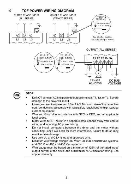
9 TCF POWER WIRING DIAGRAMTHREEPHASEINPUT
(ALLSERIES)
L1 L2 L3
OUTPUT(ALLSERIES)
3PHASEACMOTOR
DCBUSVOLTAGE
T1 T2 T3 B- B+
+
SINGLEPHASEINPUT(TF200YSERIES)
L1 L2 L3Forallothermodels,
useoutputtorquevalues .
TF230Y&TF250only
7 .0lb-in/0 .8Nm0 .24in/6mm
0 .5-5HP
(0 .37-3 .7kW)
4 .5lb-in/0 .5Nm
0 .24in/6mm
7 .5-10HP
(5 .5-7 .5kW)
10lb-in/1 .2Nm
0 .35in/9mm
STOP!
• DoNOTconnectAClinepowertooutputterminalsT1,T2,orT3 .Severedamagetothedrivewillresult .
• Leakagecurrentmayexceed3 .5mAAC .Minimumsizeoftheprotectiveearthconductorshallcomplywithlocalsafetyregulationsforhighleakagecurrentequipment .
• WireandGroundinaccordancewithNECorCEC,andallapplicablelocalcodes .
• MotorwiresMUSTberuninaseparatesteelconduitawayfromcontrolwiringandincomingACpowerwiring .
• Do not install contactors between the drive and the motor withoutconsultingLenze-ACTechformoreinformation .Failuretodosomayresultindrivedamage .
• UseonlyULandCSAlistedandapprovedwire .• Minimumwirevoltageratingis300Vfor120,208,and240Vacsystems,
and600Vfor400and480Vacsystems .• Wiregaugemustbebasedonaminimumof125%oftheratedinput/
outputcurrentofthedrive,andaminimum75°Cinsulationrating .Usecopperwireonly .
15
10 CONTROL WIRING
10 .1 CONTROLWIRINGVS .POWERWIRING
ExternalcontrolwiringMUSTbe run inaseparateconduitaway fromallother inputandoutputpowerwiring .Ifcontrolwiringisnotkeptseparatefrompowerwiring,electricalnoisemaybegeneratedonthecontrolwiringthatwillcauseerraticdrivebehavior .UsetwistedwiresorshieldedcablegroundedatthedrivechassisONLY .RecommendedcontrolwireisBelden8760or8770,orequivalent .
NOTE
Control terminals provide basic isolation (insulation per EN 61800-5-1) .Protectionagainstcontactcanonlybeassuredbyadditionalmeasurese .g .supplementalinsulation .
Strip off 0 .20 to 0 .25 inches (5 to 6 mm) of insulation for control wiring, and torque theterminalsto2lb-in(0 .2Nm) .Becarefulnottoovertorquetheterminals,asthiswillcausedamagetotheterminalstrip .Thisisnotcoveredunderwarrantyandcanonlyberepairedbyreplacingthecontrolboard .
10 .2 TB-2ANDTB-4
TheTB-2terminalsarethecircuitcommonfortheanaloginputandanalogoutputfunctions .TheTB-4terminalsarethereferenceforallofthedigitalinputs(TB-1,13A,13B,13C,and13D) .Thedigital inputsareactive-highasstandard,butcanbeconfigured foractive-lowduring initial set-up . Refer to APPENDIX B - INPUT ASSERTION LEVEL . When set foractive-high,TB-4isat+12VDC .
NOTETB-2maybeconnectedtochassisgroundifnoiseisaconcern .TB-2mustbeconnectedtochassisgroundwhenusingserialcommunications .
10 .3 SURGESUPPRESSIONONRELAYS
Currentandvoltagesurgesandspikesinthecoilsofcontactors,relays,solenoids,etc,nearor connected to thedrive, cancauseerraticdriveoperation .Therefore,asnubbercircuitshouldbeusedoncoilsassociatedwith thedrive .ForACcoils,snubbersshouldconsistof a resistor and a capacitor in series across the coil . For DC coils, a free-wheeling orflybackdiodeshouldbeplacedacross thecoil .Snubbersare typicallyavailable from themanufacturerofthedevice .
10 .4 START/STOPCONTROL
Therearevariouscontrolschemesthatallowfor2-wireand3-wireStart/Stopcircuits .RefertothewiringdiagramsinSection11-TCFCONTROLWIRINGDIAGRAMS
16
10 .5 SPEED/TORQUEREFERENCESIGNALS
SPEEDPOT ConnectthewiperofthespeedpottoterminalTB-5,andthehighandlowleadstoterminalsTB-6andTB-2,respectively .Thespeedpotcanbe2 .5kΩupto10kΩ .
0-10VDC WirethepositivetoterminalTB-5andthenegativetoterminalTB-2 .TB-5inputimpedanceis120kΩ .
-10to+10VDC ConnectthesignalwiretoTB-5andthecommontoTB-2 .TB-5inputimpedanceis120kΩ .Thissignalcanbeusedforspeedreferenceonly .
4-20mA WirethepositivetoterminalTB-25andthenegativetoterminalTB-2 .TB-25inputimpedanceis100Ω .
10 .6 SPEEDREFERENCESELECTION
Ifananalogspeed/torquereferenceinputisusedtocontrolthedrive,terminalTB-13A,13B,13C,or13D(Parameter10,11,12,or49)maybeprogrammedastheinputselectforthedesiredanaloginputsignal .WhenthatTB-13terminalisthenclosedtoTB-4,thedrivewillrespondtotheselectedanalogreferenceinput .
Ifananalogspeed/torquereferenceinputisnotselectedontheterminalstripusingTB-13A,13B,13C,or13D,controlwilldefaulttoSTANDARDmode,whichisgovernedbythesettingof Parameter 05 - STANDARD REFERENCE SOURCE . The STANDARD REFERENCESOURCEcanbethesandtbuttonsonthefrontofthedrive,PRESETSPEED#1(speedmodeonly;nottorquemode),a0-10VDCsignal,ora4-20mAsignal .
0-10VDC,-10to+10VDC,and4-20mAINPUTSIGNALS
TB-13A,TB-13B,TB-13C,andTB-13Dcanallbeprogrammedtoselecta0-10VDCor4-20mAanalogspeed/torquereferenceinput .Toselecta-10to+10VDCbipolarspeedinput,Parameter07-BIPOLARREFERENCESELECTIONmustbesettoENABLE(02),whichdisablesallotherspeedreferencesexceptforJOGFORWARDandJOGREVERSE(refertoParameter07) .
PRESETSPEEDS
TB-13A(or13D)canbeprogrammedtoselectPRESETSPEED#1,TB-13BtoselectPRESETSPEED#2,andTB-13CtoselectPRESETSPEED#3 .Thereareatotalofsevenpresetspeeds,whichareactivatedbydifferentcombinationsofcontactclosuresbetweenTB-13A(or13D),13B,13CandTB-4 .RefertoParameters31-37inSection15-DESCRIPTIONOFPARAMETERS .
JOG(notavailableinVectorTorquemode)
TB-13BcanbeprogrammedforJOGFORWARD,andTB-13CcanbeprogrammedforJOGREVERSE .TheJOGFORWARDspeedissetbyPRESETSPEED#2,andtheJOGREVERSEspeedissetbyPRESETSPEED#4 .CloseTB-13BorTB-13CtoTB-4toJOGinthedesireddirection,andopenthecontacttoSTOP .
17
WARNING!
WhenoperatinginJOGmode,theSTOPsignalandtheAUXILIARYSTOPfunction (Parameters10-12)WILLNOTstop thedrive .Tostop thedrive,removetheJOGcommand .
JOGREVERSEwilloperatethedriveinreverserotationevenifROTATIONDIRECTION(Parameter17)issettoFORWARDONLY
NOTE
If thedrive iscommandedtoJOGwhilerunning, thedrivewillenterJOGmode,butwhentheJOGcommandisremoved,thedrivewillSTOP .
MOTOROPERATEDPOT(MOP)/FLOATINGPOINTCONTROL
TB-13BandTB-13Careusedforthisfunction,whichcontrolsthedrivespeedusingcontactswiredtotheterminalstrip .ProgramTB-13BforDECREASEFREQ(05),andprogramTB-13CforINCREASEFREQ(05) .
ClosingTB-13BtoTB-4willcausethespeedsetpointtodecreaseuntilthecontactisopened .ClosingTB-13CtoTB-4willcausethespeedsetpointtoincreaseuntilthecontactisopened .TheINCREASEFREQfunctionwillonlyoperatewhilethedriveisrunning .
NOTE
IfTB-13A,TB-13B,TB-13C,andTB-13Dareallprogrammedtoselectspeedreferences,andtwoormoreoftheterminalsareclosedtoTB-4,thehigherterminalhaspriorityandwilloverride theothers .Forexample, ifTB-13A isprogrammed to select 0-10 VDC, and TB-13C is programmed to selectPRESETSPEED#3,closingboth terminals toTB-4willcause thedrive torespondtoPRESETSPEED#3becauseTB-13CoverridesTB-13A .
TheexceptiontothisistheMOPfunction,whichrequirestheuseofTB-13BandTB-13C .This leaves TB-13A and TB-13D to be used for other functions . If TB-13A or TB-13D isprogrammedforaspeedreferenceandthatterminal isclosedtoTB-4, itwilloverridetheMOPfunction .
NOTE
Thisanalogoutputsignalcannotbeusedwith"loop-powered"devicesthatderivepowerfroma4-20mAsignal .
18
10 .7 ANALOGOUTPUTSIGNALS
Terminal TB-30 can provide a 0-10 VDC or a 2-10 VDC signal proportional to outputfrequency,load,ortorque .The2-10VDCsignalcanbeconvertedtoa4-20mAsignalusingaresistorinserieswiththesignalsuchthatthetotalloadresistanceis500Ohms .RefertoTB-30OUTPUT(Parameter08)inSection15-DESCRIPTIONOFPARAMETERS .
10 .8 DRIVESTATUSDIGITALOUTPUTS
There are two open-collector outputs at terminals TB-14 and TB-15 . The open-collectorcircuitsarecurrent-sinkingtypesratedat30VDCand50mAmaximum .
The open-collector outputs can be programmed to indicate any of the following: RUN,FAULT, INVERSEFAULT,FAULTLOCKOUT,ATSPEED,ABOVEPRESETSPEED#3,CURRENTLIMIT,AUTOSPEEDMODE,andREVERSE .RefertoParameters06and13inSection15-DESCRIPTIONOFPARAMETERS .
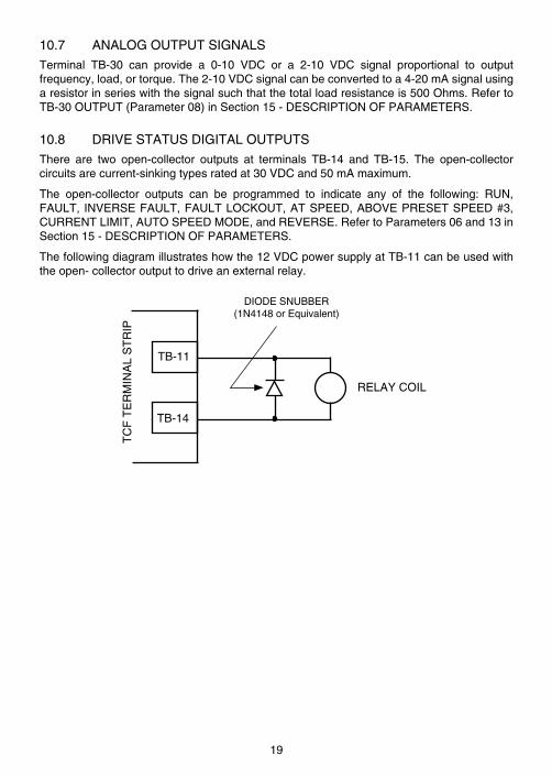
Thefollowingdiagramillustrateshowthe12VDCpowersupplyatTB-11canbeusedwiththeopen-collectoroutputtodriveanexternalrelay .
TB-11
TB-14
TC
FT
ER
MIN
AL
ST
RIP
RELAYCOIL
DIODESNUBBER(1N4148orEquivalent)
19
11 TCF CONTROL WIRING DIAGRAMS
11 .1 TCFTERMINALSTRIP
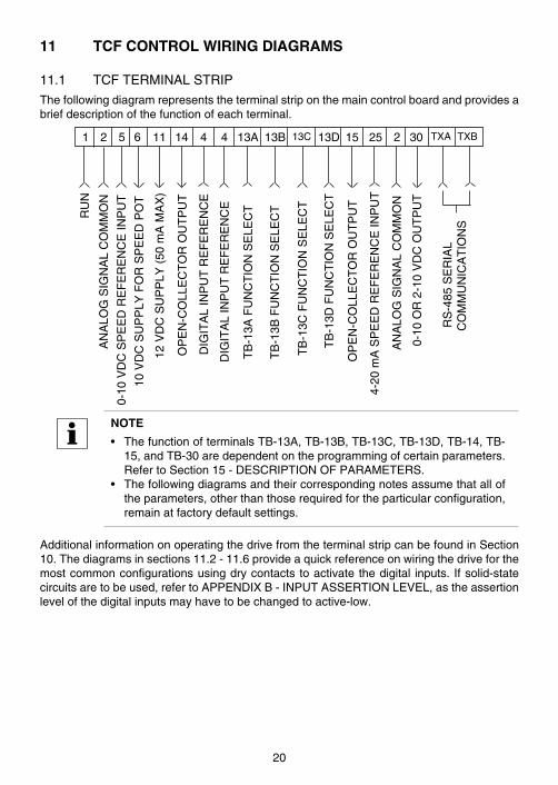
Thefollowingdiagramrepresentstheterminalstriponthemaincontrolboardandprovidesabriefdescriptionofthefunctionofeachterminal .
AN
ALO
GS
IGN
AL
CO
MM
ON
0-10
VD
CS
PE
ED
RE
FE
RE
NC
EIN
PU
T
10V
DC
SU
PP
LYF
OR
SP
EE
DP
OT
0-10
OR
2-1
0V
DC
OU
TP
UT
DIG
ITA
LIN
PU
TR
EF
ER
EN
CE
RU
N
TB
-13A
FU
NC
TIO
NS
ELE
CT
TB
-13B
FU
NC
TIO
NS
ELE
CT
TB
-13C
FU
NC
TIO
NS
ELE
CT
OP
EN
-CO
LLE
CT
OR
OU
TP
UT
OP
EN
-CO
LLE
CT
OR
OU
TP
UT
RS
-485
SE
RIA
LC
OM
MU
NIC
AT
ION
S
4-20
mA
SP
EE
DR
EF
ER
EN
CE
INP
UT
12V
DC
SU
PP
LY(
50m
AM
AX
)
1 2 5 6 14 TXA TXB4 13A 13B 13C4 13D 2511 15 302
TB
-13D
FU
NC
TIO
NS
ELE
CT
AN
ALO
GS
IGN
AL
CO
MM
ON
DIG
ITA
LIN
PU
TR
EF
ER
EN
CE
NOTE
• ThefunctionofterminalsTB-13A,TB-13B,TB-13C,TB-13D,TB-14,TB-15,andTB-30aredependentontheprogrammingofcertainparameters .RefertoSection15-DESCRIPTIONOFPARAMETERS .
• Thefollowingdiagramsandtheircorrespondingnotesassumethatalloftheparameters,otherthanthoserequiredfortheparticularconfiguration,remainatfactorydefaultsettings .
AdditionalinformationonoperatingthedrivefromtheterminalstripcanbefoundinSection10 .Thediagramsinsections11 .2-11 .6provideaquickreferenceonwiringthedriveforthemostcommonconfigurationsusingdrycontactstoactivatethedigital inputs . Ifsolid-statecircuitsaretobeused,refertoAPPENDIXB-INPUTASSERTIONLEVEL,astheassertionlevelofthedigitalinputsmayhavetobechangedtoactive-low .
20
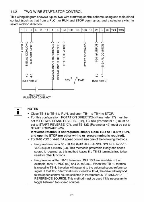
11 .2 TWO-WIRESTART/STOPCONTROL
Thiswiringdiagramshowsatypicaltwo-wirestart/stopcontrolscheme,usingonemaintainedcontact(suchasthatfromaPLC)forRUNandSTOPcommands,andaselectorswitchtoselectrotationdirection .
MAINTAINEDRUN/STOPCONTACT
SIG
NA
LC
OM
MO
N
0-10
VD
CIN
PU
T
DIG
ITA
LIN
PU
TR
EF
ER
EN
CE
ST
AR
T
ST
AR
TR
EV
ER
SE
4-20
mA
INP
UT
1 2 5 6 14 TXA TXB4 13A 13B 13C4 13D 2511 15 302
SIG
NA
LC
OM
MO
N
DIG
ITA
LIN
PU
TR
EF
ER
EN
CE
(SeeNote3)
ST
AR
TF
OR
WA
RD
FWDREV(SeeNote3)
NOTES
• CloseTB-1toTB-4toRUN,andopenTB-1toTB-4toSTOP .• Forthisconfiguration,ROTATIONDIRECTION(Parameter17)mustbe
settoFORWARDANDREVERSE(02),TB-13A(Parameter10)mustbesettoSTARTREVERSE(07),andTB-13D(Parameter49)mustbesettoSTARTFORWARD(05) .If reverse rotation is not required, simply close TB-1 to TB-4 to RUN, and open to STOP (no other wiring or programming is required).
• For0-10VDCor4-20mAspeedcontrol,useoneofthefollowingmethods:
- ProgramParameter05-STANDARDREFERENCESOURCEfor0-10VDC(03)or4-20mA(04) .Thismethodispreferableifonlyonespeedsourceisrequired,asthismethodleavestheTB-13terminalsfreetobeusedforotherfunctions .
- ProgramoneoftheTB-13terminals(13B,13Careavailableinthisexample)for0-10VDC(02)or4-20mA(03) .WhenthatTB-13terminalisclosedtoTB-4,thedrivewillrespondtotheselectedspeedreferencesignal .IfthatTB-13terminalisnotclosedtoTB-4,thedrivewillrespondtothespeedcontrolsourceselectedinParameter05-STANDARDREFERENCESOURCE .Thismethodmustbeusedifitisnecessarytotogglebetweentwospeedsources .
21
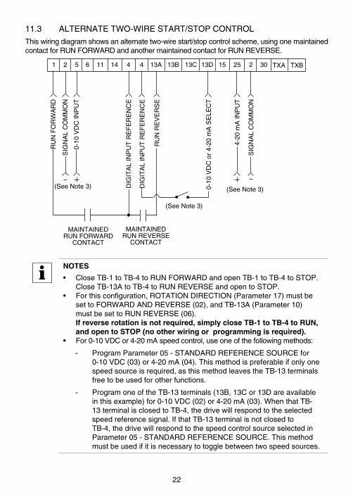
11 .3 ALTERNATETWO-WIRESTART/STOPCONTROL
Thiswiringdiagramshowsanalternatetwo-wirestart/stopcontrolscheme,usingonemaintainedcontactforRUNFORWARDandanothermaintainedcontactforRUNREVERSE .
MAINTAINEDRUNFORWARD
CONTACT
SIG
NA
LC
OM
MO
N
0-10
VD
CIN
PU
T
DIG
ITA
LIN
PU
TR
EF
ER
EN
CE
RU
NF
OR
WA
RD
RU
NR
EV
ER
SE
0-10
VD
Co
r4-
20m
AS
ELE
CT
4-20
mA
INP
UT
1 2 5 6 14 TXA TXB4 13A 13B 13C4 13D 2511 15 302
SIG
NA
LC
OM
MO
N
DIG
ITA
LIN
PU
TR
EF
ER
EN
CE
MAINTAINEDRUNREVERSE
CONTACT
(SeeNote3)
(SeeNote3) (SeeNote3)
NOTES
• CloseTB-1toTB-4toRUNFORWARDandopenTB-1toTB-4toSTOP .CloseTB-13AtoTB-4toRUNREVERSEandopentoSTOP .
• Forthisconfiguration,ROTATIONDIRECTION(Parameter17)mustbesettoFORWARDANDREVERSE(02),andTB-13A(Parameter10)mustbesettoRUNREVERSE(06) .If reverse rotation is not required, simply close TB-1 to TB-4 to RUN, and open to STOP (no other wiring or programming is required).
• For0-10VDCor4-20mAspeedcontrol,useoneofthefollowingmethods:
- ProgramParameter05-STANDARDREFERENCESOURCEfor0-10VDC(03)or4-20mA(04) .Thismethodispreferableifonlyonespeedsourceisrequired,asthismethodleavestheTB-13terminalsfreetobeusedforotherfunctions .
- ProgramoneoftheTB-13terminals(13B,13Cor13Dareavailableinthisexample)for0-10VDC(02)or4-20mA(03) .WhenthatTB-13terminalisclosedtoTB-4,thedrivewillrespondtotheselectedspeedreferencesignal .IfthatTB-13terminalisnotclosedtoTB-4,thedrivewillrespondtothespeedcontrolsourceselectedinParameter05-STANDARDREFERENCESOURCE .Thismethodmustbeusedifitisnecessarytotogglebetweentwospeedsources .
22
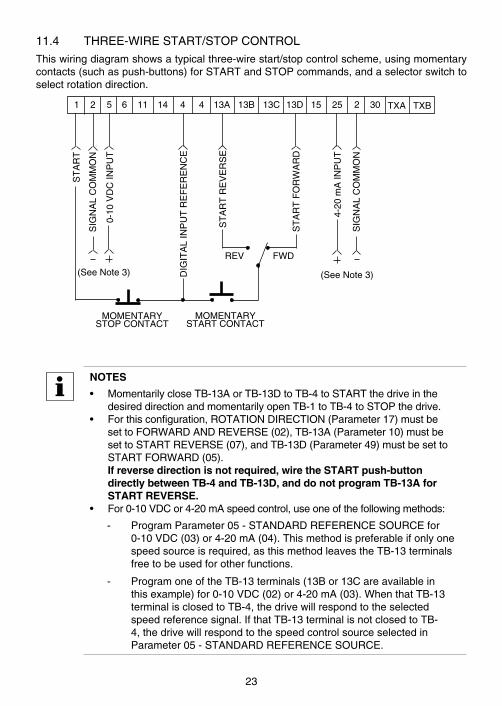
11 .4 THREE-WIRESTART/STOPCONTROL
Thiswiringdiagramshowsatypicalthree-wirestart/stopcontrolscheme,usingmomentarycontacts(suchaspush-buttons)forSTARTandSTOPcommands,andaselectorswitchtoselectrotationdirection .
MOMENTARYSTOPCONTACT
SIG
NA
LC
OM
MO
N
0-10
VD
CIN
PU
T
DIG
ITA
LIN
PU
TR
EF
ER
EN
CE
ST
AR
T
4-20
mA
INP
UT
1 2 5 6 14 TXA TXB4 13A 13B 13C4 13D 2511 15 302
SIG
NA
LC
OM
MO
N
(SeeNote3)
ST
AR
TF
OR
WA
RD
MOMENTARYSTARTCONTACT
(SeeNote3)
FWDREV
ST
AR
TR
EV
ER
SE
NOTES
• MomentarilycloseTB-13AorTB-13DtoTB-4toSTARTthedriveinthedesireddirectionandmomentarilyopenTB-1toTB-4toSTOPthedrive .
• Forthisconfiguration,ROTATIONDIRECTION(Parameter17)mustbesettoFORWARDANDREVERSE(02),TB-13A(Parameter10)mustbesettoSTARTREVERSE(07),andTB-13D(Parameter49)mustbesettoSTARTFORWARD(05) .If reverse direction is not required, wire the START push-button directly between TB-4 and TB-13D, and do not program TB-13A for START REVERSE.
• For0-10VDCor4-20mAspeedcontrol,useoneofthefollowingmethods:
- ProgramParameter05-STANDARDREFERENCESOURCEfor0-10VDC(03)or4-20mA(04) .Thismethodispreferableifonlyonespeedsourceisrequired,asthismethodleavestheTB-13terminalsfreetobeusedforotherfunctions .
- ProgramoneoftheTB-13terminals(13Bor13Careavailableinthisexample)for0-10VDC(02)or4-20mA(03) .WhenthatTB-13terminalisclosedtoTB-4,thedrivewillrespondtotheselectedspeedreferencesignal .IfthatTB-13terminalisnotclosedtoTB-4,thedrivewillrespondtothespeedcontrolsourceselectedinParameter05-STANDARDREFERENCESOURCE .
23
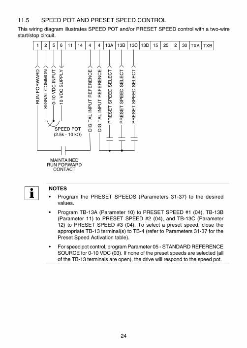
11 .5 SPEEDPOTANDPRESETSPEEDCONTROL
ThiswiringdiagramillustratesSPEEDPOTand/orPRESETSPEEDcontrolwithatwo-wirestart/stopcircuit .
MAINTAINEDRUNFORWARD
CONTACT
SIG
NA
LC
OM
MO
N
0-10
VD
CIN
PU
T
DIG
ITA
LIN
PU
TR
EF
ER
EN
CE
RU
NF
OR
WA
RD
PR
ES
ET
SP
EE
DS
ELE
CT
1 2 5 6 14 TXA TXB4 13A 13B 13C4 13D 2511 15 302
DIG
ITA
LIN
PU
TR
EF
ER
EN
CE
PR
ES
ET
SP
EE
DS
ELE
CT
PR
ES
ET
SP
EE
DS
ELE
CT
10V
DC
SU
PP
LY
SPEEDPOT(2 .5k-10kΩ)
NOTES
• Program the PRESET SPEEDS (Parameters 31-37) to the desiredvalues .
• ProgramTB-13A(Parameter10)toPRESETSPEED#1(04),TB-13B(Parameter11) toPRESETSPEED#2 (04), andTB-13C (Parameter12) toPRESETSPEED#3 (04) .To select a preset speed, close theappropriateTB-13terminal(s)toTB-4(refertoParameters31-37forthePresetSpeedActivationtable) .
• Forspeedpotcontrol,programParameter05-STANDARDREFERENCESOURCEfor0-10VDC(03) .Ifnoneofthepresetspeedsareselected(alloftheTB-13terminalsareopen),thedrivewillrespondtothespeedpot .
24

11 .6 BIPOLARSPEEDCONTROL(-10to+10VDC)
Thethreewiringdiagramshereinprovideexamplesofusinga-10to+10VDCbipolarspeedreference .
SIG
NA
LC
OM
MO
N
0-10
VD
CIN
PU
T
1 2 5 6 11
-10to+10VDCSOURCE
(suchasPLC)
SIG
NA
LC
OM
MO
N
0-10
VD
CIN
PU
T1 2 5 6 11
10V10V
SPEEDPOT(2 .5k-10kΩ)
- + - +
SIG
NA
LC
OM
MO
N
0-10
VD
CIN
PU
T
1 2 5 6 11
+10
VD
CS
UP
PLY
10V
SPEEDPOT(2 .5k-10kΩ)
- + (COM)(SIGNAL)
NOTES:
• Tousea-10to+10VDCspeedreferencesignal,thefollowingparametersmustbeset:
P07 BIPOLARREFERENCESELECTIONmustbesettoENABLE(02) .
P17 ROTATIONmustbesettoFORWARDANDREVERSE(02) .
P45 SPEED AT MIN SIGNAL must be set to the maximum desiredspeedinthereversedirection .
P46 SPEEDATMAXSIGNALmustbeset to themaximumdesiredspeedintheforwarddirection .
• Inthisconfiguration,allotherspeedreferencesaredisabledexceptJOGFORWARDandJOGREVERSE .
• In this configuration, the RUN and START functions on TB-13A andTB-13Dwillonlystartthedrive,theywillnotselectdirection .Directionisdeterminedbythepolarityofthe-10to+10VDCsignal .
25
12 INITIAL POWER UP AND MOTOR ROTATION
DANGER!
Hazardofelectricalshock!Capacitors retain charge after power is removed . Disconnect incomingpowerandwaituntil thevoltagebetween terminalsB+andB- is0VDCbeforeservicingthedrive .
STOP!
• DoNOTconnectincomingACpowertooutputterminalsT1,T2,andT3!Severedamagetothedrivewillresult .
• DoNOTcontinuouslycycle inputpower to thedrivemore thanonceeverytwominutes .Damagetothedrivewillresult .
• SeveredamagetothedrivecanresultifitisoperatedafteralongperiodofstorageorinactivitywithoutreformingtheDCbuscapacitors!
Ifinputpowerhasnotbeenappliedtothedriveforaperiodoftimeexceedingthreeyears(duetostorage,etc),theelectrolyticDCbuscapacitorswithinthedrivecanchangeinternally,resultinginexcessiveleakagecurrent .Thiscanresultinprematurefailureofthecapacitorsifthedriveisoperatedaftersuchalongperiodofinactivityorstorage .
Inordertoreformthecapacitorsandpreparethedriveforoperationafteralongperiodofinactivity,applyinputpowertothedrivefor8hourspriortoactuallyoperatingthemotor .
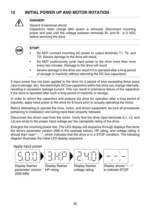
Beforeattemptingtooperatethedrive,motor,anddrivenequipment,besureallprocedurespertainingtoinstallationandwiringhavebeenproperlyfollowed .
Disconnectthedrivenloadfromthemotor .Verifythatthedriveinputterminals(L1,L2,andL3)arewiredtotheproperinputvoltageperthenameplateratingofthedrive .
Energizetheincomingpowerline .TheLEDdisplaywillsequencethroughdisplaysthatshowthedrive'sparameterversion(500intheexamplebelow),HPrating,andvoltagerating .Itshouldthenread“---”,whichindicatesthatthedriveisinaSTOPcondition .ThefollowingdiagramillustratestheinitialLEDdisplaysequence .
Display flashes HP rating
Apply input power
Display flashes parameter version (500-599)
Display shows "- - -" to indicate STOP
Display flashes voltage rating
26

Followtheprocedurebelowtocheckthemotorrotation .Thisprocedureassumesthatthedrivehasbeenpoweredupfor thefirst time,andthatnoneof theparametershavebeenchanged .
1 . Usethetbuttontodecreasethespeedsetpointto00 .0Hz .Ifthetbuttonishelddown,thespeedsetpointwilldecreasebytenthsofHzuntilthenextwholeHzisreached,andthenitwilldecreasebyoneHzincrements .Otherwise,eachpushofthetbuttonwilldecreasethespeedsetpointbyatenthofaHz .
Once00 .0Hzisreached,thedisplaywilltogglebetween“00 .0”and“---”,whichindicatesthatthedriveisinaSTOPconditionwithaspeedsetpointof00 .0Hz .
2 . GivethedriveaSTARTcommand .ThiscanbedoneusingoneofseveralwiringmethodsdescribedinSection11-TCFCONTROLWIRINGDIAGRAMS .OncetheSTARTcommandisissued,thedisplaywillread“00 .0”,indicatingthatthedriveisinaRUNconditionwithaspeedsetpointof00 .0Hz .
3 . Usethesbuttontoincreasethespeedsetpointuntilthemotorstartstorotate .Ifthesbuttonishelddown,thespeedsetpointwillincreasebytenthsofHzuntilthenextwholeHzisreached,andthenitwillincreasebyoneHzincrements .Otherwise,eachpushofthebuttonwillincreasethespeedsetpointbyatenthofaHz .
4 . Ifthemotorisrotatinginthewrongdirection,givethedriveaSTOPcommandandremovepowerfromthedrive .Waitthreeminutesforthebuscapacitorstodischarge,andswapanytwoofthemotorwiresconnectedtoT1,T2,andT3 .
NOTE
Thedrive isphase insensitivewith respect to incoming linevoltage .Thismeansthatthedrivewilloperatewithanyphasesequenceoftheincomingthreephasevoltage .Therefore, tochange themotor rotation, thephasesmustbeswappedatthedriveoutputterminalsoratthemotor .
27
13 PROGRAMMING THE TCF DRIVEThedrivemaybeprogrammedbyoneofthreemethods:usingthethreebuttonsand3-digitLEDdisplayonthefrontofthedrive,programmingtheElectronicProgrammingModule(EPM)usingtheoptionalEPMProgrammer,andthroughaseriallinkusingserialcommunications .Thissectiondescribesprogrammingthedriveusingthebuttonsanddisplay .
NOTE
Refer toAppendixA for informationonoperating theTCFSeriesdrive invectormode .
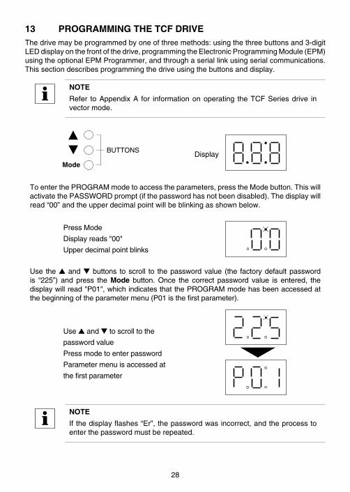
BUTTONS
Mode
Display
ToenterthePROGRAMmodetoaccesstheparameters,presstheModebutton .ThiswillactivatethePASSWORDprompt(ifthepasswordhasnotbeendisabled) .Thedisplaywillread“00”andtheupperdecimalpointwillbeblinkingasshownbelow .
PressMode
Displayreads"00"
Upperdecimalpointblinks
Use thesandtbuttons toscroll to thepasswordvalue (the factorydefaultpasswordis “225”) and press the Mode button . Once the correct password value is entered, thedisplaywillread"P01",whichindicatesthatthePROGRAMmodehasbeenaccessedatthebeginningoftheparametermenu(P01isthefirstparameter) .
Usesandttoscrolltothe
passwordvalue
Pressmodetoenterpassword
Parametermenuisaccessedat
thefirstparameter
NOTE
Ifthedisplayflashes“Er”,thepasswordwasincorrect,andtheprocesstoenterthepasswordmustberepeated .
28
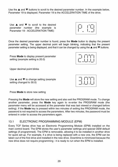
Usethesandtbuttonstoscrolltothedesiredparameternumber .Intheexamplebelow,Parameter19isdisplayed .Parameter19istheACCELERATIONTIMEofthedrive .
Use s and t to scroll to the desiredparameter number (the example isParameter19-ACCELERATIONTIME)
Once thedesiredparameternumber is found,press theModebutton todisplay thepresentparameter setting . The upper decimal point will begin blinking, indicating that the presentparametersettingisbeingdisplayed,andthatitcanbechangedbyusingthesandtbuttons .
PressModetodisplaypresentparametersetting(examplesettingis20 .0)
Upperdecimalpointblinks
Usesandttochangesetting(examplesettingchangedto30 .0)
PressModetostorenewsetting
PressingtheModewillstorethenewsettingandalsoexitthePROGRAMmode .Tochangeanother parameter, press the Mode key again to re-enter the PROGRAM mode (theparametermenuwillbeaccessedattheparameterthatwaslastviewedorchangedbeforeexiting) .IftheModekeyispressedwithintwominutesofexitingthePROGRAMmode,thepasswordisnotrequiredtoaccesstheparameters .Aftertwominutes,thepasswordmustbeenteredinordertoaccesstheparametersagain .
13 .1 ELECTRONICPROGRAMMINGMODULE(EPM)
Every TCF Series drive has an Electronic Programming Module (EPM) installed on themaincontrolboard .TheEPMstorestheuser’sparametersettingsandspecialOEMdefaultsettings(ifprogrammed) .TheEPMisremovable,allowingittobeinstalledinanotherdriveforquickset-up .Forexample,ifadriveisbeingreplacedwithanewone,theEPMcanbetakenoutofthefirstdriveandinstalledinthenewdrive .Downtimeisminimizedbecausethenewdrivedoesnotrequireprogramming-itisreadytorunwhentheEPMisinstalled .
29

TheTCFSeriesdrivecontainstwoorthreesetsofparametervalues,dependingonwhetherthedrivehasbeenprogrammedwithoptionalOEMdefaultsettings .Thefirstsetofvaluesis the factory default settings, which are permanently stored on the main control boardandcannotbechanged .Thesecondsetofvaluesistheusersettings,whicharestoredintheEPM .Whenthedriveleavesthefactory,theusersettingsarethesameasthefactorydefaultsettings,buttheusersettingscanbechangedtoconfigurethedriveforaparticularapplication .
TheoptionalthirdsetofvaluesistheOEMdefaultsettings,whicharealsostoredintheEPM .OEMdefaultsettingsaretypicallyusedincaseswheremanydrivesareusedforthesameapplication,whichrequiresthatallofthedriveshavethesameparametersettings .TheOEMdefaultsettingscannotbechangedwithouttheoptionalEPMProgrammer .ThedrivecanbeprogrammedtooperateaccordingtotheusersettingsortheOEMdefaultsettings(refertoParameter48inSection15) .
NOTEThedrivewillnotoperatewithouttheEPMinstalled .Thedrivewilldisplay“F1”if theEPMismissingordamaged .TheTCFdrivewillonlyworkwithblueEPMs;theblackEPMswillnotwork .
STOP!
DoNOTremovetheEPMwhilepowerisappliedtothedrive .DamagetotheEPMand/ordrivemayresult .
TheEPMProgrammer,availableasanoptionfromLenze-ACTech,hastheabilitytoquicklyandeasilyprogrammanyTCFSeriesdrivesforthesameconfiguration .Oncea“master”EPMisprogrammedwith thedesiredparametersettings, theEPMProgrammercancopy thosesettingstootherEPMs,allowingmanydrivestobeconfiguredveryquickly .ConsulttheEPMProgrammerInstructionManualorcontactLenze-ACTechformoreinformation .
IftheOEMsettingsintheEPMbecomecorrupted,thedrivewilloperatenormally,untilanattemptismadetoperformaRESETOEMusingParameter48-PROGRAMSELECTION .Thedrivewillthenflash“GF”toindicatethattheOEMsettingsarenolongervalid .ThiswillrequirethattheEPMbere-programmedusingtheoptionalEPMProgrammer .
If the OEM settings and the user settings are both corrupted, the drive will display “GF”immediately and the drive will require a RESET 60 or RESET 50 using Parameter 48 -PROGRAM SELECTION . Once the RESET is performed, the parameters can then beprogrammed individually to match the OEM default settings . This will allow the drive tooperateasifitwereinOEMmode,eventhoughitisactuallyoperatinginUSERmode .RefertoParameter48inSection15-DESCRIPTIONOFPARAMETERS .
NOTE
Thedrivewillalsodisplay“GF”ifaRESETOEMorOPERATEWITHOEMSETTINGSisattemptedwhentheEPMdoesnotcontainOEMdefaults .
30
13 .2 TCFDRIVEPERSONALITY
EachTCFmodelhasaunique"personality"(voltageandHP) .ThisinformationisstoredintheEPM,andisalsopermanentlystoredwithinthedrive .If theEPMisreplaced,andthepersonalitystoredintheEPMdoesnotmatchthepersonalitystoredinthedrive,itmaytripintoa"bF"fault,dependingontheinformationstoredonthenewEPM .
1 . IfthenewEPMwasfromaTCFdrivethatwasconfiguredforV/Hzmode(refertoParameter80-DRIVEMODE),thedrivewilloperatenormallyandwillnottripintoa"bF"fault .TosetupthedriveforVectormode,followtheinstructionsinAppendixA .
2 . IfthenewEPMwasfromaTCFdrivethatwasconfiguredforVectormodeorEnhancedV/Hzmode(refertoParameter80-DRIVEMODE),thedrivewilltripintoa"bF"fault .Thisfaultcanberesetbyoneoftwomethods:a . PerformaRESET60orRESET50usingParameter48-PROGRAM
SELECTION .Thiswillresetalloftheparametersbacktofactorydefaults .TosetupthedriveforVectororEnhancedV/Hzmode,followtheinstructionsinAppendixA .
b . Setparameters85-91properlyfortheconnectedmotorandthensetParameter94-DRIVEPERSONALITYtothecorrectvaluebasedontheHPandvoltageratingofthedrive .ThenperformtheAutoCalibrationfunctionaccordingtotheinstructionsinAppendixA .
NOTE
If an attempt is made to change Parameter 94 - DRIVE PERSONALITYbeforeparameters85-91arechanged,thedrivewilldisplaya"GH"fault .
31
14 PARAMETER MENU
NO. PARAMETER NAME RANGE OF ADJUSTMENTFACTORYDEFAULT
(NOTE1)
01 LINEVOLTAGE HIGH(01),LOW(02) HIGH(01)
02 CARRIERFREQUENCY 2kHz(01),4kHz(02),8kHz(03) 4kHz(02)
03 STARTMETHOD
NORMAL(01),STARTONPOWERUP(02),
NORMAL(01)
STARTWITHDCBRAKE(03),
AUTORESTARTWITHDCBRAKE(04),
FLYINGRESTART1(05),
FLYINGRESTART2(06)
04 STOPMETHODCOAST(01),COASTWITHDCBRAKE(02),
COAST(01)RAMP(03),RAMPWITHDCBRAKE(04)
05STANDARD
REFERENCESOURCE
speed mode:KEYPAD(01),PRESET#1(02),
KEYPAD(01)0-10VDC(03),4-20mA(04)
torque mode:KEYPAD(01),KEYPAD(02),
0-10VDC(03),4-20mA(04)
0613
TB-14OUTPUTTB-15OUTPUT
NONE(01),RUN(02),FAULT(03),
NONE(01)NONE(01)
INVERSEFAULT(04),FAULTLOCKOUT(05),
ATSETSPEED(06),ABOVEPRESET#3(07),
CURRENTLIMIT(08),AUTOSPEED(09),
REVERSE(10),DYNAMICBRAKING(11)
07 BIPOLARREFERENCESELECTION
DISABLE(01),ENABLE(02) DISABLE(01)
08 TB-30OUTPUT
NONE(01),0-10VDCFREQ(02),
NONE(01)2-10VDCFREQ(03),0-10VDCLOAD(04),
2-10VDCLOAD(05),0-10VDCTORQUE(06),
2-10VDCTORQUE(07)
10TB-13A
FUNCTIONSELECT
NONE(01),0-10VDC(02),4-20mA(03),
NONE(01)
PRESETSPEED#1(04),
STARTFORWARD(05),RUNREVERSE(06),
STARTREVERSE(07),EXTERNALFAULT(08),
REMOTEKEYPAD(09),DBFAULT(10),
AUXILIARYSTOP(11),ACCEL/DECEL#2(12)
NOTE1:Factorydefaultsareshownfora60Hzbasefrequency .RefertoParameter48for50Hzbasefrequency .
32
NO. PARAMETER NAME RANGE OF ADUSTMENTFACTORYDEFAULT
(NOTE1)
11TB-13BFUNCTION
SELECT
NONE(01),0-10VDC(02),4-20mA(03),
NONE(01)PRESETSPEED#2(04),DECREASEFREQ(05),
JOGFORWARD(06),AUXILIARYSTOP(07)
12TB-13CFUNCTION
SELECT
NONE(01),0-10VDC(02),4-20mA(03),
NONE(01)
PRESETSPEED#3(04),INCREASEFREQ(05),
EXTERNALFAULT(06),REMOTEKEYPAD(07),
DBFAULT(08),JOGREVERSE(09),
ACCEL/DECEL#2(10)
13 TB-15OUTPUT (SEEPARAMETER6-TB-14OUTPUT) NONE(01)
14 CONTROL
TERMINALSTRIPONLY(01),TERMINALSTRIP
ONLY(01)REMOTEKEYPADONLY(02),
TERMINALSTRIPORREMOTEKEYPAD(03)
15 SERIALLINK
DISABLE(01),9600,8,N,2WITHTIMER(02),
9600,8,N,2WITHOUTTIMER(03),
9600,8,E,1WITHTIMER(04), 9600,8,N,2
9600,8,E,1WITHOUTTIMER(05), WITHTIMER(02)
9600,8,O,1WITHTIMER(06),
9600,8,O,1WITHOUTTIMER(07)
17 ROTATIONFORWARDONLY(01), FORWARD
FORWARDANDREVERSE(02) ONLY(01)
18 MTROVERLOADTYPE SPEEDCOMP(01),NOCOMP(02) SPEEDCOMP(01)
19 ACCELERATIONTIME 0 .1-1300 .0SEC 20 .0SEC
20 DECELERATIONTIME 0 .1-1300 .0SEC 20 .0SEC
21 DCBRAKETIME 0 .0-999 .0SEC 0 .0SEC
22 DCBRAKEVOLTAGE 0 .0-30 .0% 0 .00%
23 MINIMUMFREQUENCY 0 .0-MAXIMUMFREQUENCY 0 .0Hz
24 MAXIMUMFREQUENCY MINIMUMFREQ-240 .0Hz 60 .0Hz
25 CURRENTLIMIT 50-200%(NOTE2) 200%
26 MOTOROVERLOAD 30-100% 100%
27 BASEFREQUENCY 25 .0-500 .0Hz 60 .0Hz
NOTE1:Factorydefaultsareshownfora60Hzbasefrequency .RefertoParameter48for50Hzbasefrequency .NOTE2:IfLINEVOLTAGEissettoLOW,maximumsettingis167% .
33
NO. PARAMETER NAME RANGE OF ADJUSTMENTFACTORYDEFAULT
(NOTE1)
28 FIXEDBOOST 0 .0-30 .0% 1 .0%
29 ACCELBOOST 0 .0-20 .0% 0 .0%
30 SLIPCOMPENSATION 0 .0-5 .0% 0 .0%
31-37 PRESETSPEEDS 0 .0-MAXIMUMFREQUENCY 0 .0Hz
38 SKIPBANDWIDTH 0 .0-10 .0Hz 0 .0Hz
39 SPEEDSCALING 0 .0-6500 .0 0 .0
40 FREQUENCYSCALING 3 .0-1200 .0Hz 60 .0Hz
41 LOADSCALING 10-200% 200%
42 ACCEL/DECEL#2 0 .1-1300 .0SEC 20 .0SEC
43 SERIALADDRESS 1-247 1
44 PASSWORD 000-999 225
45 SPEEDATMINSIGNAL 0 .0-999Hz 0 .0Hz
46 SPEEDATMAXSIGNAL 0 .0-999Hz 60 .0Hz
47 CLEARHISTORY MAINTAIN(01),CLEAR(02) MAINTAIN(01)
48 PROGRAMSELECTION
USERSETTINGS(01),OEMSETTINGS(02),USERSETTINGS
(01)RESETOEM(03),RESET60(04),
RESET50(05),TRANSLATE(06)
49TB-13D
FUNCTIONSELECT
NONE(01),0-10VDC(02),4-20mA(03),
NONE(01)
PRESETSPEED#1(04),
STARTFORWARD(05),
EXTERNALFAULT(06),
REMOTEKEYPAD(07),DBFAULT(08),
AUXILIARYSTOP(09),ACCEL/DECEL#2(10)
50 SOFTWARECODE (VIEW-ONLY) (N/A)
51 SOFTWARECODE (VIEW-ONLY) (N/A)
52 DCBUSVOLTAGE (VIEW-ONLY) (N/A)
53 MOTORVOLTAGE (VIEW-ONLY) (N/A)
54 LOAD (VIEW-ONLY) (N/A)
55 0-10VDCINPUT (VIEW-ONLY) (N/A)
56 4-20mAINPUT (VIEW-ONLY) (N/A)
NOTE1:Factorydefaultsareshownfora60Hzbasefrequency .RefertoParameter48for50Hzbasefrequency .
34

NO. PARAMETER NAME RANGE OF ADJUSTMENTFACTORYDEFAULT
(NOTE1)
57 TBSTRIPSTATUS (VIEW-ONLY) (N/A)
58 KEYPADSTATUS (VIEW-ONLY) (N/A)
59 TB-30OUTPUT (VIEW-ONLY) (N/A)
73 HEATSINKTEMP (VIEW-ONLY) (N/A)
79INPUTASSERTION
LEVELHIGH(01),LOW(02) HIGH(01)
80 DRIVEMODE
CONSTANTV/Hz(01),VARIABLEV/Hz(02),
CONSTANTV/Hz(01)
ENHANCEDCONSTANTV/Hz(03),
ENHANCEDVARIABLEV/Hz(04),
VECTORSPEED(05),VECTORTORQUE(06)
81 AUTOCALIBRATION
CALIBRATIONNOTDONE(00),CALIBRATION
NOTDONE(00)CALIBRATIONCYCLEENABLED(01),
CALIBRATIONCOMPLETE(02)
82 CURRENTLOOPPGAIN 0 .00-16 .0 0 .25
83 CURRENTLOOPIGAIN 12-9990mSEC 65mSEC
84 STATORRESISTANCE 0 .00-64 .0OHMS(NOTE3) 0 .00OHMS
85 MOTORRATEDSPEED 300-65000RPM 1750RPM
86 MOTORRATEDAMPS 0 .0-480AMPS 0 .0AMPS
87 MOTORRATEDVOLTS 0-600Vac 0Vac
88 MOTORBASEFREQ 25-500Hz 60Hz
91 MOTORCOSINEPHI 0 .40-0 .99 0 .80
92 MOTORINDUCTANCE 0 .0-2000mH(NOTE3) 0 .0mH
93 TORQUELIMIT 0-400% 100%
94 DRIVEPERSONALITY (NOTE4) (NOTE4)
95 MOTORCURRENT (VIEW-ONLY) (N/A)
96 TORQUEPERCENT (VIEW-ONLY) (N/A)
NOTE1:Factorydefaultsareshownfora60Hzbasefrequency .RefertoParameter48for50Hzbasefrequency .NOTE3:ThisparameterisautomaticallysetduringtheAUTOCALIBRATIONfunction .NOTE4:RefertoSection15-DESCRIPTIONOFPARAMETERS .
35
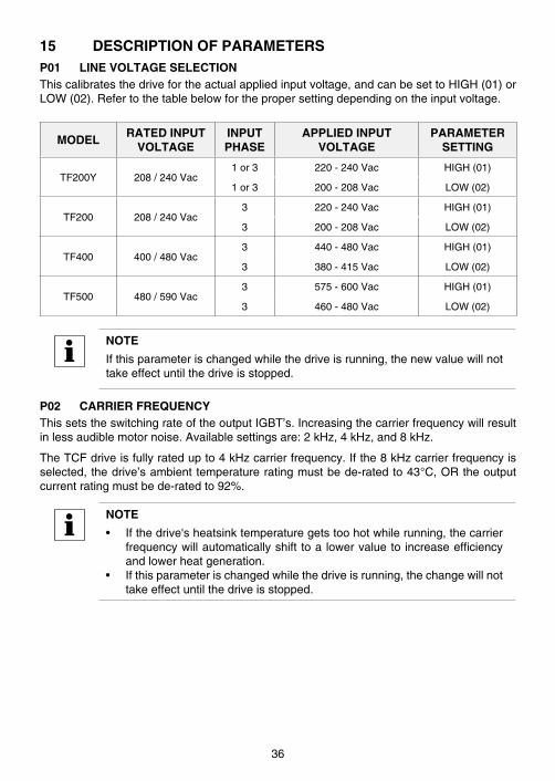
15 DESCRIPTION OF PARAMETERSP01 LINE VOLTAGE SELECTIONThiscalibratesthedrivefortheactualappliedinputvoltage,andcanbesettoHIGH(01)orLOW(02) .Refertothetablebelowforthepropersettingdependingontheinputvoltage .
MODELRATED INPUT
VOLTAGEINPUTPHASE
APPLIED INPUTVOLTAGE
PARAMETERSETTING
TF200Y 208/240Vac1or3 220-240Vac HIGH(01)
1or3 200-208Vac LOW(02)
TF200 208/240Vac3 220-240Vac HIGH(01)
3 200-208Vac LOW(02)
TF400 400/480Vac3 440-480Vac HIGH(01)
3 380-415Vac LOW(02)
TF500 480/590Vac3 575-600Vac HIGH(01)
3 460-480Vac LOW(02)
NOTE
Ifthisparameterischangedwhilethedriveisrunning,thenewvaluewillnottakeeffectuntilthedriveisstopped .
P02 CARRIER FREQUENCYThissetstheswitchingrateoftheoutputIGBT’s .Increasingthecarrierfrequencywillresultinlessaudiblemotornoise .Availablesettingsare:2kHz,4kHz,and8kHz .
TheTCFdriveisfullyratedupto4kHzcarrierfrequency .Ifthe8kHzcarrierfrequencyisselected,thedrive’sambienttemperatureratingmustbede-ratedto43°C,ORtheoutputcurrentratingmustbede-ratedto92% .
NOTE
• Ifthedrive'sheatsinktemperaturegetstoohotwhilerunning,thecarrierfrequencywillautomaticallyshift toalowervalueto increaseefficiencyandlowerheatgeneration .
• Ifthisparameterischangedwhilethedriveisrunning,thechangewillnottakeeffectuntilthedriveisstopped .
36
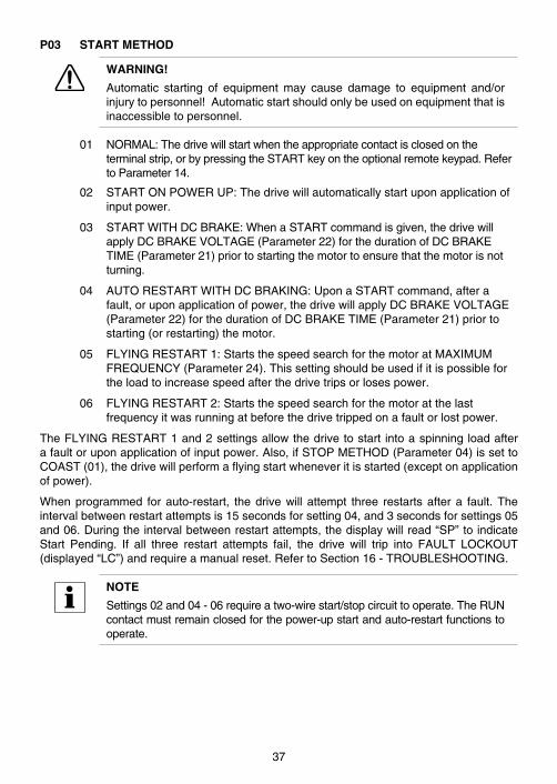
P03 START METHOD
WARNING!
Automatic starting of equipment may cause damage to equipment and/orinjurytopersonnel!Automaticstartshouldonlybeusedonequipmentthatisinaccessibletopersonnel .
01 NORMAL:Thedrivewillstartwhentheappropriatecontactisclosedontheterminalstrip,orbypressingtheSTARTkeyontheoptionalremotekeypad .RefertoParameter14 .
02 STARTONPOWERUP:Thedrivewillautomaticallystartuponapplicationofinputpower .
03 STARTWITHDCBRAKE:WhenaSTARTcommandisgiven,thedrivewillapplyDCBRAKEVOLTAGE(Parameter22)forthedurationofDCBRAKETIME(Parameter21)priortostartingthemotortoensurethatthemotorisnotturning .
04 AUTORESTARTWITHDCBRAKING:UponaSTARTcommand,afterafault,oruponapplicationofpower,thedrivewillapplyDCBRAKEVOLTAGE(Parameter22)forthedurationofDCBRAKETIME(Parameter21)priortostarting(orrestarting)themotor .
05 FLYINGRESTART1:StartsthespeedsearchforthemotoratMAXIMUMFREQUENCY(Parameter24) .Thissettingshouldbeusedifitispossiblefortheloadtoincreasespeedafterthedrivetripsorlosespower .
06 FLYINGRESTART2:Startsthespeedsearchforthemotoratthelastfrequencyitwasrunningatbeforethedrivetrippedonafaultorlostpower .
TheFLYINGRESTART1and2settingsallowthedrivetostart intoaspinningloadafterafaultoruponapplicationofinputpower .Also,ifSTOPMETHOD(Parameter04)issettoCOAST(01),thedrivewillperformaflyingstartwheneveritisstarted(exceptonapplicationofpower) .
Whenprogrammed forauto-restart, thedrivewill attempt three restartsaftera fault .Theintervalbetweenrestartattemptsis15secondsforsetting04,and3secondsforsettings05and06 .Duringtheintervalbetweenrestartattempts,thedisplaywillread“SP”toindicateStart Pending . If all three restart attempts fail, the drive will trip into FAULT LOCKOUT(displayed“LC”)andrequireamanualreset .RefertoSection16-TROUBLESHOOTING .
NOTE
Settings02and04-06requireatwo-wirestart/stopcircuittooperate .TheRUNcontactmustremainclosedforthepower-upstartandauto-restartfunctionstooperate .
37
P04 STOP METHOD01 COASTTOSTOP:WhenaSTOPcommandisgiven,thedriveshutsoffthe
outputtothemotor,allowingittocoastfreelytoastop .
02 COASTWITHDCBRAKE:Whenastopcommandisgiven,thedrivewillactivateDCbraking(afteradelayofupto2seconds,dependingonfrequency)tohelpdeceleratetheload .RefertoParameters:21-DCBRAKETIME,and22-DCBRAKEVOLTAGE .
03 RAMPTOSTOP:Whenastopcommandisgiven,thedrivewilldeceleratethemotortoastopattheratedeterminedbyParameter20-DECELERATIONTIME .
04 RAMPWITHDCBRAKE:Whenastopcommandisgiven,thedrivewilldeceleratethemotordownto0 .2Hz(attheratesetbyParameter20-DECELERATIONTIME)andthenactivateDCbrakingaccordingtothesettingsofParameters21-DCBRAKETIMEand22-DCBRAKEVOLTAGE .Thisisusedtobringtheloadtoafinalstop,asthemotormaystillbeturningslightlyafterthedrivestops .
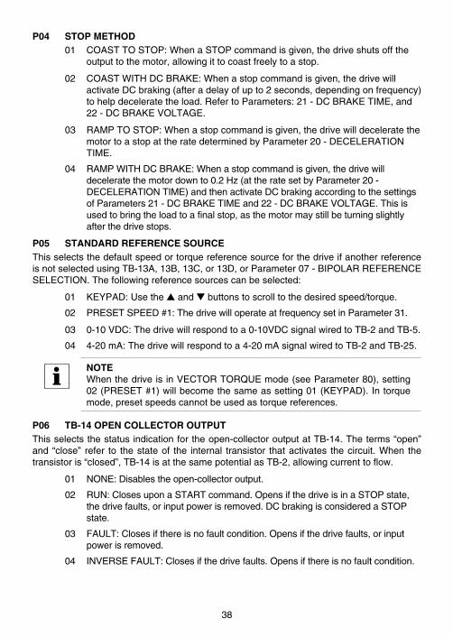
P05 STANDARD REFERENCE SOURCEThisselectsthedefaultspeedortorquereferencesourceforthedriveifanotherreferenceisnotselectedusingTB-13A,13B,13C,or13D,orParameter07-BIPOLARREFERENCESELECTION .Thefollowingreferencesourcescanbeselected:
01 KEYPAD:Usethesandtbuttonstoscrolltothedesiredspeed/torque .
02 PRESETSPEED#1:ThedrivewilloperateatfrequencysetinParameter31 .
03 0-10VDC:Thedrivewillrespondtoa0-10VDCsignalwiredtoTB-2andTB-5 .
04 4-20mA:Thedrivewillrespondtoa4-20mAsignalwiredtoTB-2andTB-25 .
NOTEWhenthedriveisinVECTORTORQUEmode(seeParameter80),setting02(PRESET#1)willbecomethesameassetting01(KEYPAD) .Intorquemode,presetspeedscannotbeusedastorquereferences .
P06 TB-14 OPEN COLLECTOR OUTPUTThisselectsthestatusindicationfortheopen-collectoroutputatTB-14 .Theterms“open”and “close” refer to thestateof the internal transistor thatactivates thecircuit .When thetransistoris“closed”,TB-14isatthesamepotentialasTB-2,allowingcurrenttoflow .
01 NONE:Disablestheopen-collectoroutput .
02 RUN:ClosesuponaSTARTcommand .OpensifthedriveisinaSTOPstate,thedrivefaults,orinputpowerisremoved .DCbrakingisconsideredaSTOPstate .
03 FAULT:Closesifthereisnofaultcondition .Opensifthedrivefaults,orinputpowerisremoved .
04 INVERSEFAULT:Closesifthedrivefaults .Opensifthereisnofaultcondition .
38

05 FAULTLOCKOUT:Closeswheninputpowerisapplied .Opensifthreerestartattemptsareunsuccessful,orifinputpowerisremoved .
06 ATSETSPEED:Closesifthedriveiswithin+0 .5Hzofthespeedsetpoint .
07 ABOVEPRESETSPEED#3:ClosesiftheoutputfrequencyexceedsthevalueinPRESETSPEED#3 .OpensiftheoutputfrequencyisequaltoorlessthanthevalueinPRESETSPEED#3(Parameter33) .
08 CURRENTLIMIT:ClosesiftheoutputcurrentexceedstheCURRENTLIMITsetting .OpensiftheoutputcurrentisequaltoorlessthanCURRENTLIMIT(refertoParameter25) .
09 AUTOMATICSPEEDMODE:ClosesifanAUTOMATIC(terminalstrip)speedreferenceisselectedusingTB-13A,13B,13C,or13D .OpensifaSTANDARD(Parameter5)speedreferenceisactive .
10 REVERSE:Closeswhenreverserotationisactive .Openswhenforwardrotationisactive .(RefertoParameter17-ROTATIONDIRECTION) .
11 DYNAMICBRAKING:Usedto"trigger"theoptionalexternalDynamicBrakingmodule .RefertotheinstructionsincludedwiththeDynamicBrakingoption .
P07 BIPOLAR REFERENCE SELECTIONThisparameterisusedtoenablethe-10to+10VDCbipolarspeedreferenceinput(cannotbeusedasatorquereference) .RefertoSection11 .6for-10to+10VDCwiringexamples .
01 DISABLE:ThedrivewilloperatenormallyandrespondtothespeedreferenceselectedinParameter5-STANDARDREFERENCESOURCE,orselectedusingterminals13A,13B,13C,and13D .RefertoSection10 .6formoreinformationonspeedreferenceselection .
02 ENABLE:Thedrivewillonlyrespondtoa-10to+10VDCbipolarsignal(allotherspeedreferencesaredisabled) .
From+0 .1to+10VDCthedrivewilloperateintheForwarddirection,withthemaximumspeeddeterminedbySPEEDATMAXSIGNAL(Parameter46)orMAXIMUMFREQUENCY(Parameter24),whicheverislower .
From-0 .1to-10VDC,thedrivewilloperateintheReversedirection,withthemaximumspeeddeterminedbySPEEDATMINSIGNAL(Parameter45)orMAXIMUMFREQUENCY(Parameter24),whicheverislower .
NOTE
• Whensetting02isselected,Parameter17-ROTATIONmustbesettoFORWARDANDREVERSE(02)forthebipolarspeedreferencetoworkproperly .
• Whensetting02isselected,theRUNandSTARTfunctionsonterminalsTB-13AandTB-13Dcanonlybeusedtostartthedrive;theywillnolongerselectdirection(directionisonlydeterminedbythepolarityofthe-10to+10VDCsignal) .However,TB-13BandTB-13CcanstillbeusedforJOGFORWARDandJOGREVERSEfunctions .
RefertoParameters10,11,12,and49
39
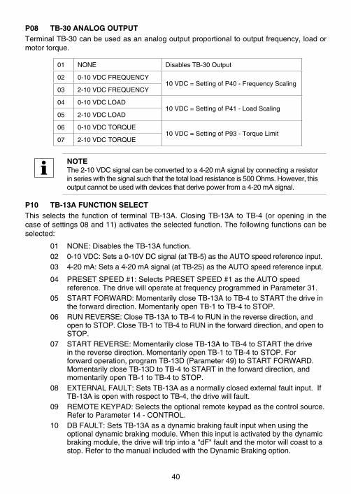
P08 TB-30 ANALOG OUTPUTTerminalTB-30canbeusedasananalogoutputproportionaltooutputfrequency,loadormotortorque .
01 NONE DisablesTB-30Output
02 0-10VDCFREQUENCY10VDC=SettingofP40-FrequencyScaling
03 2-10VDCFREQUENCY
04 0-10VDCLOAD10VDC=SettingofP41-LoadScaling
05 2-10VDCLOAD
06 0-10VDCTORQUE10VDC=SettingofP93-TorqueLimit
07 2-10VDCTORQUE
NOTEThe2-10VDCsignalcanbeconvertedtoa4-20mAsignalbyconnectingaresistorinserieswiththesignalsuchthatthetotalloadresistanceis500Ohms .However,thisoutputcannotbeusedwithdevicesthatderivepowerfroma4-20mAsignal .
P10 TB-13A FUNCTION SELECTThis selects the function of terminal TB-13A . Closing TB-13A to TB-4 (or opening in thecaseofsettings08and11)activatestheselectedfunction .Thefollowingfunctionscanbeselected:
01 NONE:DisablestheTB-13Afunction .02 0-10VDC:Setsa0-10VDCsignal(atTB-5)astheAUTOspeedreferenceinput .03 4-20mA:Setsa4-20mAsignal(atTB-25)astheAUTOspeedreferenceinput .
04 PRESETSPEED#1:SelectsPRESETSPEED#1astheAUTOspeedreference .ThedrivewilloperateatfrequencyprogrammedinParameter31 .
05 STARTFORWARD:MomentarilycloseTB-13AtoTB-4toSTARTthedriveintheforwarddirection .MomentarilyopenTB-1toTB-4toSTOP .
06 RUNREVERSE:CloseTB-13AtoTB-4toRUNinthereversedirection,andopentoSTOP .CloseTB-1toTB-4toRUNintheforwarddirection,andopentoSTOP .
07 STARTREVERSE:MomentarilycloseTB-13AtoTB-4toSTARTthedriveinthereversedirection .MomentarilyopenTB-1toTB-4toSTOP .Forforwardoperation,programTB-13D(Parameter49)toSTARTFORWARD .MomentarilycloseTB-13DtoTB-4toSTARTintheforwarddirection,andmomentarilyopenTB-1toTB-4toSTOP .
08 EXTERNALFAULT:SetsTB-13Aasanormallyclosedexternalfaultinput .IfTB-13AisopenwithrespecttoTB-4,thedrivewillfault .
09 REMOTEKEYPAD:Selectstheoptionalremotekeypadasthecontrolsource .RefertoParameter14-CONTROL .
10 DBFAULT:SetsTB-13Aasadynamicbrakingfaultinputwhenusingtheoptionaldynamicbrakingmodule .Whenthisinputisactivatedbythedynamicbrakingmodule,thedrivewilltripintoa"dF"faultandthemotorwillcoasttoastop .RefertothemanualincludedwiththeDynamicBrakingoption .
40
11 AUXILIARYSTOP:WhenTB-13AisopenedwithrespecttoTB-4,thedrivewilldeceleratetoaSTOP(evenifSTOPMETHODissettoCOAST)attherateprogrammedintoParameter42-ACCEL/DECEL#2 .
12 ACCEL/DECEL#2:SelectstheaccelerationanddecelerationtimeprogrammedintoParameter42-ACCEL/DECEL#2 .
NOTE
• InorderfortheRUNREVERSEandSTARTREVERSEfunctionstooperate,Parameter17-ROTATIONDIRECTIONmustbesettoFORWARDANDREVERSE(02) .
• Ifa-10to+10VDCbipolarspeedreferenceisbeingused(Parameter07-BIPOLARREFERENCESELECTIONisENABLED),theRUNandSTARTfunctionsonTB-13Awillonlystartthedrive,theywillnotselectdirection .Directionisdeterminedbythepolarityofthe-10to+10VDCsignal .
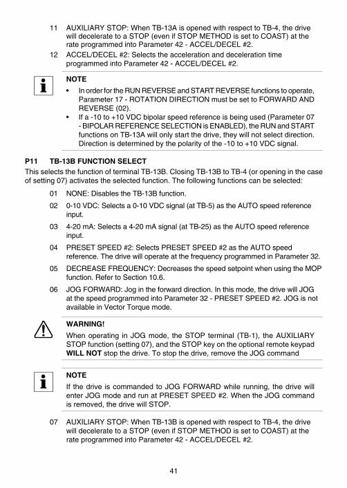
P11 TB-13B FUNCTION SELECTThisselectsthefunctionofterminalTB-13B .ClosingTB-13BtoTB-4(oropeninginthecaseofsetting07)activatestheselectedfunction .Thefollowingfunctionscanbeselected:
01 NONE:DisablestheTB-13Bfunction .
02 0-10VDC:Selectsa0-10VDCsignal(atTB-5)astheAUTOspeedreferenceinput .
03 4-20mA:Selectsa4-20mAsignal(atTB-25)astheAUTOspeedreferenceinput .
04 PRESETSPEED#2:SelectsPRESETSPEED#2astheAUTOspeedreference .ThedrivewilloperateatthefrequencyprogrammedinParameter32 .
05 DECREASEFREQUENCY:DecreasesthespeedsetpointwhenusingtheMOPfunction .RefertoSection10 .6 .
06 JOGFORWARD:Jogintheforwarddirection .Inthismode,thedrivewillJOGatthespeedprogrammedintoParameter32-PRESETSPEED#2 .JOGisnotavailableinVectorTorquemode .
WARNING!
Whenoperating inJOGmode, theSTOP terminal (TB-1), theAUXILIARYSTOPfunction(setting07),andtheSTOPkeyontheoptionalremotekeypadWILL NOTstopthedrive .Tostopthedrive,removetheJOGcommand
NOTE
If thedrive iscommandedtoJOGFORWARDwhilerunning, thedrivewillenterJOGmodeandrunatPRESETSPEED#2 .WhentheJOGcommandisremoved,thedrivewillSTOP .
07 AUXILIARYSTOP:WhenTB-13BisopenedwithrespecttoTB-4,thedrivewilldeceleratetoaSTOP(evenifSTOPMETHODissettoCOAST)attherateprogrammedintoParameter42-ACCEL/DECEL#2 .
41
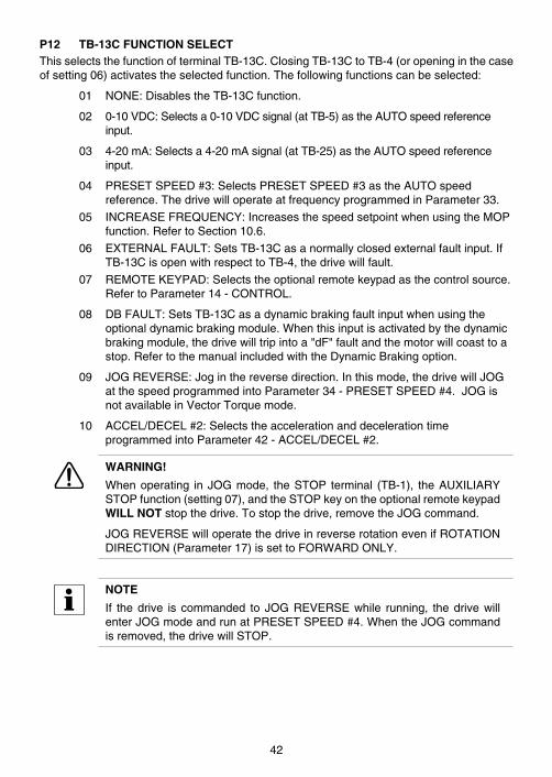
P12 TB-13C FUNCTION SELECTThisselectsthefunctionofterminalTB-13C .ClosingTB-13CtoTB-4(oropeninginthecaseofsetting06)activatestheselectedfunction .Thefollowingfunctionscanbeselected:
01 NONE:DisablestheTB-13Cfunction .
02 0-10VDC:Selectsa0-10VDCsignal(atTB-5)astheAUTOspeedreferenceinput .
03 4-20mA:Selectsa4-20mAsignal(atTB-25)astheAUTOspeedreferenceinput .
04 PRESETSPEED#3:SelectsPRESETSPEED#3astheAUTOspeedreference .ThedrivewilloperateatfrequencyprogrammedinParameter33 .
05 INCREASEFREQUENCY:IncreasesthespeedsetpointwhenusingtheMOPfunction .RefertoSection10 .6 .
06 EXTERNALFAULT:SetsTB-13Casanormallyclosedexternalfaultinput .IfTB-13CisopenwithrespecttoTB-4,thedrivewillfault .
07 REMOTEKEYPAD:Selectstheoptionalremotekeypadasthecontrolsource .RefertoParameter14-CONTROL .
08 DBFAULT:SetsTB-13Casadynamicbrakingfaultinputwhenusingtheoptionaldynamicbrakingmodule .Whenthisinputisactivatedbythedynamicbrakingmodule,thedrivewilltripintoa"dF"faultandthemotorwillcoasttoastop .RefertothemanualincludedwiththeDynamicBrakingoption .
09 JOGREVERSE:Joginthereversedirection .Inthismode,thedrivewillJOGatthespeedprogrammedintoParameter34-PRESETSPEED#4 .JOGisnotavailableinVectorTorquemode .
10 ACCEL/DECEL#2:SelectstheaccelerationanddecelerationtimeprogrammedintoParameter42-ACCEL/DECEL#2 .
WARNING!
Whenoperating inJOGmode, theSTOP terminal (TB-1), theAUXILIARYSTOPfunction(setting07),andtheSTOPkeyontheoptionalremotekeypadWILL NOTstopthedrive .Tostopthedrive,removetheJOGcommand .
JOGREVERSEwilloperatethedriveinreverserotationevenifROTATIONDIRECTION(Parameter17)issettoFORWARDONLY .
NOTE
If thedrive is commanded to JOGREVERSEwhile running, thedrivewillenterJOGmodeandrunatPRESETSPEED#4 .WhentheJOGcommandisremoved,thedrivewillSTOP .
42
P13 TB-15 OPEN COLLECTOR OUTPUT
Thisselectsthestatusindicationfortheopen-collectoroutputatTB-15,andhasthesameselectionsasParameter6-TB-14OPENCOLLECTOROUTPUT .
P14 CONTROLThisselectsthesourceofSTART/STOPanddirectioncommands .
01 TERMINALSTRIPONLY:ThedrivewillonlyrespondtoSTART/STOPanddirectioncommandsfromtheterminalstrip .
02 REMOTEKEYPADONLY:ThedrivewillonlyrespondtoSTART/STOPanddirectioncommandsfromtheoptionalremotekeypad .
03 TERMINALSTRIPORREMOTEKEYPAD:TerminalTB-13A,TB-13C,orTB-13Dcanbeusedtoselectterminalstripcontrolorremotekeypadcontrol .RefertoParameters10,12,and49 .
NOTE
TheSTOPbuttonontheoptionalremotekeypadisalwaysactiveaslongastheseriallinkremainsintact .
P15 SERIAL LINKThisparameterconfiguresthedriveforModbusRTUserialcommunications .Theoptionsarelistedbybaudrate,numberofdatabits,parity,numberofstopbitsandwhetherthewatchdogtimerisenabledordisabled .
WARNING!
Controlling the drive from the serial link without the watchdog timer couldcausedamagetoequipmentand/orinjurytopersonnel!
Thewatchdog timerwill stop thedriveafter10secondsofnoserialactivity tosafeguardagainstafailedseriallink .Duringset-uportroubleshootingitmaybeusefultodisablethewatchdogtimerbutisitnotrecommendedtorunnormallywithoutthewatchdogtimer .
01 DISABLED:Disablestheseriallink
02 9600,8,N,2-ENABLEDWITHTIMER
03 9600,8,N,2-ENABLEDWITHOUTTIMER
04 9600,8,E,1-ENABLEDWITHTIMER
05 9600,8,E,1-ENABLEDWITHOUTTIMER
06 9600,8,O,1-ENABLEDWITHTIMER
07 9600,8,O,1-ENABLEDWITHOUTTIMER
43

P17 ROTATION DIRECTION01 FORWARDONLY:Thedrivewillonlyallowrotationintheforwarddirection .
However,JOGREVERSE(Parameter12)willstilloperateevenifFORWARDONLYisselected .
02 FORWARDANDREVERSE:Thedrivewillallowrotationinbothdirections .
P18 MOTOR OVERLOAD TYPE01 SPEEDCOMPENSATED:Below40Hz,thecontinuouscurrentratingis
reducedtoprotectstandardmotorsthatcannotcoolthemselveseffectivelyatlowspeeds .From40Hzto0Hz,theallowablecontinuouscurrentdecreasesfrom100%to62% .
02 NOCOMPENSATION:Fullratedcurrentisavailablethroughoutthespeedrange .Onlyusethissettingifthemotorisratedforlowspeedoperationunderhighloads .
P19 ACCELERATION TIMEThisparametersets theacceleration rate forallof thespeedreferencesources (keypad,speedpot,4-20mA,0-10VDC,-10to+10VDC,jog,MOP,andpresetspeeds) .Thissettingisthetimetoacceleratefrom0HztotheBASEFREQUENCY(Parameter27) .
P20 DECELERATION TIMEThisparametersets thedecelerationrate forallof thespeedreferencesources(keypad,speedpot,4-20mA,0-10VDC,-10to+10VDC,jog,MOP,andpresetspeeds) .ThissettingisthetimetodeceleratefromBASEFREQUENCYto0Hz .IfthedriveissetforCOASTTOSTOP(setting01or02inParameter04),thisparameterwillhavenoeffectwhenaSTOPcommandisgiven .
P21 DC BRAKE TIMEThisdeterminesthelengthoftimethattheDCbrakingvoltageisappliedtothemotor .IfDCBRAKETIMEissetto999 .0SEC(themaximumvalue),theDCbrakingwillbecontinuous(theDCbrakingwillbeonwheneverthedriveisinaSTOPstate) .TheDCBRAKETIMEshouldbesettothelowestvaluethatprovidessatisfactoryoperationinordertominimizemotorheating .
P22 DC BRAKE VOLTAGEThissetsthemagnitudeof theDCbrakingvoltage, inpercentageof thenominalDCBusvoltage(DCBus=inputACvoltageX1 .414) .ThepointatwhichtheDCbrakingisactivateddependsontheselectedSTOPMETHOD(Parameter04):
IfCOASTWITHDCBRAKEisselected,theDCbrakingisactivatedafteratimedelayofupto2seconds,dependingontheoutputfrequencyatthetimeoftheSTOPcommand .Inthiscase,theDCbrakingistheonlyforceactingtodeceleratetheload .
If RAMP WITH DC BRAKE is selected, braking is activated when the output frequencyreaches0 .2Hz .Inthiscase,thedrivedeceleratestheloadtoanearstopandtheDCbrakingisusedtobringtheloadtoafinalstop .
P23 MINIMUM FREQUENCYThissetstheminimumoutputfrequencyofthedriveforallspeedreferencesourcesexceptthePRESETSPEEDS(Parameters31-37) .
44

NOTE
If either the Minimum Frequency or Maximum Frequency parameter ischangedwhilethedriveisrunning,thenewvaluewillnottakeeffectuntilthedriveisstopped .
P24 MAXIMUM FREQUENCYThissetsthemaximumoutput frequencyof thedriveforallspeedreferencesourcesandisusedwithMINIMUMFREQUENCY(Parameter23)todefinetheoperatingrangeofthedrive .
P25 CURRENT LIMITThissetsthemaximumallowableoutputcurrentofthedrive .Themaximumsettingiseither200%or167%,dependingonwhetherLINEVOLTAGESELECTION(Parameter01)issettoHIGHorLOW .
ThedrivewillentercurrentlimitwhentheloaddemandsmorecurrentthantheCURRENTLIMITsetting .Whenthishappens,thedrivewillreducetheoutputfrequencyinanattempttoreducetheoutputcurrent .Whentheoverloadconditionpasses,thedrivewillacceleratethemotorbackuptothespeedsetpoint .
P26 MOTOR OVERLOADTheTCFSeriesisULapprovedforsolidstatemotoroverloadprotectionandthereforedoesnotrequireaseparatethermaloverloadrelayforsinglemotorapplications .
The drive contains an adjustable thermal overload circuit that protects the motor fromexcessiveovercurrent .Thiscircuitallows thedrive todeliverup to150%current foroneminute .Iftheoverloadcircuit“timesout”,thedrivewilltripintoanOVERLOADfault(displayedas"PF") .
MOTOROVERLOADshouldbesettotheratio(inpercent)ofthemotorcurrentratingtothedrivecurrentratinginordertoproperlyprotectthemotor .Refertotheexampleherein .
Example: A3HP,480Vacdrivewitha4 .8Amprating isoperatinga2HPmotorwithacurrentratingof3 .4Amps .Dividingthemotorcurrentratingbythedrivecurrentratingyields71%(3 .4/4 .8=0 .71=71%),sothisparametershouldbesetto71% .
P27 BASE FREQUENCYBASEFREQUENCYisactiveonlyinV/Hzmode(Parameter80)anddeterminestheV/Hzratiobysettingtheoutputfrequencyatwhichthedrivewilloutputfullvoltagetothemotor .InmostcasestheBASEFREQUENCYshouldbesettomatchthemotor’sratedfrequency .
Example: A 460 Vac, 60 Hz motor requires a V/Hz ratio of 7 .67 (460 V / 60 Hz = 7 .67V/Hz)toproducefulltorque .SettingtheBASEFREQUENCYto60Hzcausesthedrivetooutputfullvoltage(460Vac)at60Hz,whichyieldstherequired7 .67V/Hz .Outputvoltageisproportionaltooutputfrequency,sothe7 .67V/Hzratioismaintainedfrom0-60Hz,allowingthemotortoproducefulltorquefrom2Hz(below2Hzthereislesstorqueduetoslip)upto60Hz .
NOTEIfthisparameterischangedwhilethedriveisrunning,thenewvaluewillnottakeeffectuntilthedriveisstopped .
45

P28 FIXED BOOSTFIXEDBOOSTisactiveonlyinV/Hzmode(refertoParameter80),andincreasesstartingtorqueby increasingtheoutputvoltagewhenoperatingbelowhalfof thebasefrequency,whichincreasestheV/Hzratio .ThefactorydefaultsettingdependsonHPrating,asshowninthefollowingtable .
HP DEFAULT HP DEFAULT
0 .5-1 2 .0% 5 1 .2%
1 .5-2 1 .8% 7 .5 1 .0%
3 1 .5% 10 1 .0%
P29 ACCELERATION BOOSTACCELERATIONBOOSTisactiveonly inV/Hzmode(refer toParameter80),andhelpsacceleratehigh-inertialoads .Duringaccelerationtheoutputvoltageisincreasedtoincreasemotortorque .Oncethemotorreachesthenewspeedsetpointtheboostisturnedoff .
P30 SLIP COMPENSATIONSLIPCOMPENSATION isactiveonly inV/Hzmode (refer toParameter80)and isusedto counteract changes in motor speed (slip) caused by changes in load . In a standardAC inductionmotor, theshaft speeddecreasesas load increasesand increasesas loaddecreases .Byincreasingordecreasingtheoutputfrequencyinresponsetoanincreasingordecreasingload,theslipiscounteractedandspeedismaintained .MoststandardNEMABmotorshavea3%sliprating .
P31-P37 PRESET SPEED #1 - #7PresetspeedsareactivatedbycontactclosuresbetweenTB-4andTB-13A(or13D),13Band13C .TheTB-13terminalsmustbeprogrammedaspresetspeedselectsusingParameters10,11,12and49 .PresetSpeeds#2and#4arealsousedwhenthedriveisinJOGmode .RefertoParameters11and12 .PresetspeedsarenotavailableinVectorTorquemode .
NOTE
Preset speeds can operate below the frequency defined by MINIMUMFREQUENCY(Parameter23) .Therangeofadjustmentforthepresetspeedsisfrom0HztoMAXIMUMFREQUENCY(Parameter24) .
46
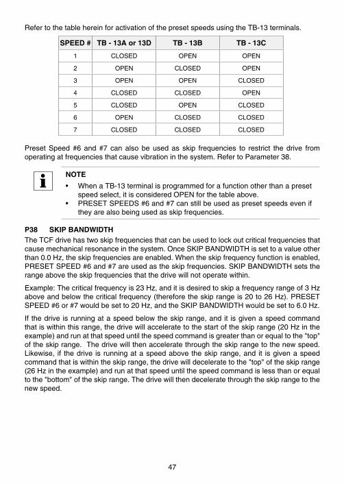
RefertothetablehereinforactivationofthepresetspeedsusingtheTB-13terminals .
SPEED # TB - 13A or 13D TB - 13B TB - 13C
1 CLOSED OPEN OPEN
2 OPEN CLOSED OPEN
3 OPEN OPEN CLOSED
4 CLOSED CLOSED OPEN
5 CLOSED OPEN CLOSED
6 OPEN CLOSED CLOSED
7 CLOSED CLOSED CLOSED
Preset Speed #6 and #7 can also be used as skip frequencies to restrict the drive fromoperatingatfrequenciesthatcausevibrationinthesystem .RefertoParameter38 .
NOTE
• WhenaTB-13terminalisprogrammedforafunctionotherthanapresetspeedselect,itisconsideredOPENforthetableabove .
• PRESETSPEEDS#6and#7canstillbeusedaspresetspeedseveniftheyarealsobeingusedasskipfrequencies .
P38 SKIP BANDWIDTHTheTCFdrivehastwoskipfrequenciesthatcanbeusedtolockoutcriticalfrequenciesthatcausemechanicalresonanceinthesystem .OnceSKIPBANDWIDTHissettoavalueotherthan0 .0Hz,theskipfrequenciesareenabled .Whentheskipfrequencyfunctionisenabled,PRESETSPEED#6and#7areusedastheskipfrequencies .SKIPBANDWIDTHsetstherangeabovetheskipfrequenciesthatthedrivewillnotoperatewithin .
Example:Thecriticalfrequencyis23Hz,anditisdesiredtoskipafrequencyrangeof3Hzaboveandbelowthecriticalfrequency(thereforetheskiprangeis20to26Hz) .PRESETSPEED#6or#7wouldbesetto20Hz,andtheSKIPBANDWIDTHwouldbesetto6 .0Hz .
If thedrive isrunningataspeedbelowtheskiprange,andit isgivenaspeedcommandthatiswithinthisrange,thedrivewillacceleratetothestartoftheskiprange(20Hzintheexample)andrunatthatspeeduntilthespeedcommandisgreaterthanorequaltothe"top"oftheskiprange .Thedrivewillthenacceleratethroughtheskiprangetothenewspeed .Likewise, if thedrive is runningataspeedabove theskiprange,and it isgivenaspeedcommandthatiswithintheskiprange,thedrivewilldeceleratetothe"top"oftheskiprange(26Hzintheexample)andrunatthatspeeduntilthespeedcommandislessthanorequaltothe"bottom"oftheskiprange .Thedrivewillthendeceleratethroughtheskiprangetothenewspeed .
47

P39 SPEED SCALINGThisscalesthedisplaytoindicatespeedoruserunitsotherthanfrequency .Thisparametershouldbesettothedesireddisplayvaluewhenthedriveoutputis60Hz .Thehighestsettingis6500,andthehighestvaluethatcanbedisplayedis6553 .6 .
Example: A machine produces 175 parts per hour when the motor is running at 60 Hz .SettingtheSPEEDSCALINGto175willcalibratethedrive'sdisplaytoread175whenthemotorisrunningat60Hz .Thisisalinearfunction,soat30Hzthedisplaywouldread87 .5,andat120Hz,thedisplaywouldread350 .v
NOTEIfSPEEDSCALINGissetsuchthatthemaximumdisplayedvalue(6553 .6)isexceeded,thedisplaywillflash"9999"toindicatethatthevalueisoutofrange .Forexample,ifSPEEDSCALINGissetto6000,thedrivewilldisplay6000 when it is running at 60 Hz . If the speed is increased past 65 .5 Hz(at65 .5Hz, thescaledvaluewouldbe6550), thedisplaywillflash"9999"becauseascaledvalueabove6553 .6cannotbedisplayed .
P40 FREQUENCY SCALINGThisscalestheanalogoutputsignalatTB-30whenitisconfiguredforafrequencyoutput .Thissetting is theoutput frequency that is indicatedwhentheoutputsignalmeasures10VDC .
Example:A0-5VDCsignalisrequiredtoindicate0-60Hz .Settingthisparameterto120Hzwouldyield10VDCat120Hz,and5VDCat60Hz .Ifthedriveonlyoperatesupto60Hz,theoutputsignalatTB-30islimitedtothedesired0-5VDC .
P41 LOAD SCALINGThisscalestheanalogoutputsignalatTB-30whenitisconfiguredforaloadoutput .Thissettingistheload(in%)thatisindicatedwhentheoutputsignalmeasures10VDC .
Example:A0-10VDCsignalisrequiredtoindicate0-150%load .Settingthisparameterto150%willyield10VDCat150%load .
P42 ACCEL/DECEL #2Thisparametersetsthesecondaccelerationanddecelerationrateofthedrive .Toactivatethisaccelerationanddecelerationrate,useterminalsTB-13A,TB-13B,TB-13C,orTB-13D .TB-13A,TB-13BandTB-13DcanbesettoAUXILIARYSTOPwhichwillcausethedrivetodeceleratetoastopaccordingtothetimeprogrammedinthisparameter .TB-13A,TB-13Cand TB-13D can be set to ACCEL/DECEL #2 which causes the drive to accelerate anddecelerateaccordingtothetimeprogrammedinthisparameter .
P43 SERIAL ADDRESSIfaseriallinkisbeingusedtocommunicatewithmultipledrives,eachdrivemustbegivenadifferentaddress(from1to247)sothatanindividualdriveinthenetworkcanbeaccessed .
48

P44 PASSWORDThisallowsthePASSWORDtobechangedtoanynumberbetween000and999 .SettingPASSWORDto000disablesthepasswordfunction .
NOTE
Thefactorydefaultpasswordis225 .
P45 SPEED AT MIN SIGNALThissetsthespeedatwhichthedrivewillrunwhenitreceivestheminimumspeedreferencesignal(0VDCor4mA) .ThisisusedinconjunctionwithSPEEDATMAXSIGNAL(Parameter46)todefinethespeedrangeofthedrivewhenfollowingananalogspeedreferencesignal .
NOTE
Whenthedriveisconfiguredfor-10to+10VDCspeedcontrol,SPEEDATMINSIGNALwillsetthemaximumspeedthatthedrivewillrunatinreversedirection when it receives -10 VDC . Refer to Parameter 07 - BIPOLARREFERENCESELECTION .
P46 SPEED AT MAX SIGNALThissetsthespeedatwhichthedrivewillrunwhenitreceivesthemaximumspeedreferencesignal(10VDCor20mA) .ThisisusedinconjunctionwithSPEEDATMINSIGNAL(Parameter45)todefinethespeedrangeofthedrivewhenfollowingananalogspeedreferencesignal .
NOTE
If SPEED AT MIN SIGNAL is set higher than SPEED AT MAX SIGNAL, thedrivewillreactinverselytothespeedreferencesignal .Therefore,asthespeedreferencesignal increases, thedrivespeedwilldecrease,andvice-versa .Thisfunctionisdisabledwhenusinga-10to+10VDCspeedreferencesignal .RefertoParameter07-BIPOLARREFERENCESELECTION .
P47 CLEAR FAULT HISTORY01 MAINTAIN:MaintainstheFAULTHISTORY(Parameter50)entriesfor
troubleshooting .
02 CLEAR:ErasestheFAULTHISTORY(Parameter50)entries .
49

P48 PROGRAM SELECTIONThis isused toselectwhether thedrivewilloperateaccording to theusersettingsor theoptional OEM default settings and to reset the parameters to default settings . Refer toSection13 .1 .
01 OPERATEWITHUSERSETTINGS:Thedrivewilloperateaccordingtotheusersettings .OperationinUSERmodeallowstheparametervaluestobechangedtosuitanyapplication .
02 OPERATEWITHOEMDEFAULTS:ThedrivewilloperateaccordingtotheoptionalOEMdefaultsettings,whichconfigurethedriveforaspecificapplication .WhenoperatinginOEMmode,theparametervaluescanbeviewed,butnotchanged .Ifanattemptismadetochangeaparametersetting,thedisplaywillflash“GE” .IfthedriveisnotprogrammedwithOEMdefaultsettings,thedisplaywillflash“GF”ifthisoptionisselected .
03 RESETOEM:ResetstheuserparameterstotheOEMdefaultsettings .IfthedriveisnotprogrammedwithOEMdefaultsettings,thedisplaywillflash“GF”ifthisoptionisselected .
04 RESET60:Resetstheuserparameterstothefactorydefaultsfora60Hzbasefrequency .
05 RESET50:Resetstheuserparameterstothefactorydefaultsfora50Hzbasefrequency .Parameters24,27,40,46and88willresetto50 .0Hz,andParameter85willresetto1450RPM .
06 TRANSLATE:IfanEPMfromadrivewithapreviousparameterversionisinstalledinanewdrive,thenewdrivewillfunctionlikethepreviousversiondrive,butnoneoftheparametersettingscanbechanged("cE"willbedisplayedifthisisattempted) .TheTRANSLATEfunctionconvertstheEPMtothenewparameterversionsothattheparameterscanbechanged,butitalsoretainstheoldparametersettingssothenewdrivewilloperateliketheolddrivewithouthavingtore-programalloftheparameters .
NOTE
• IftheuserparametersareresettotheOEMdefaults(usingtheRESETOEMoption),andthenOPERATEWITHUSERSETTINGSisselected,theUSERsettingswillbethesameastheOEMdefaultsettings .ThisallowsthedrivetooperateasifitwasinOEMmode,buttheparametervaluescanbechanged .ThisisusefulifsomeoftheOEMdefaultsettingsneedtobefine-tunedforproperoperation .Thenewparametervaluesarenotactually storedasnewOEMdefault settingshowever; theyaresimplystoredasnewUSERsettings .Therefore,iftheparametersareresettotheOEMdefaultsagaintheparametersthatwerechangedwillberesettotheir“old”value .TheoptionalEPMProgrammerisrequiredtochangeOEMdefaultsettings .RefertoSection13 .2 .
• OnlytheTRANSLATE(06)functioncanbeperformedwhilethedriveisrunning .Thedisplaywillflash“Er”ifanattemptismadetoselectanyotherfunctionwhilethedriveisrunning .
50
P49 TB-13D FUNCTION SELECTThisselectsthefunctionofterminalTB-13D .ClosingTB-13DtoTB-4(oropeninginthecaseofsettings06and09)activatestheselectedfunction .Thesefunctionsareselectable:
01 NONE:DisablestheTB-13Dfunction .
02 0-10VDC:Selectsa0-10VDCsignal(atTB-5)astheAUTOspeedreferenceinput .
03 4-20mA:Selectsa4-20mAsignal(atTB-25)astheAUTOspeedreferenceinput .
04 PRESETSPEED#1:SelectsPRESETSPEED#1astheAUTOspeedreference .ThedrivewilloperateatthefrequencyprogrammedintoParameter31 .
05 STARTFORWARD:MomentarilycloseTB-13DtoTB-4toSTARTintheforwarddirection,andmomentarilyopenTB-1toTB-4toSTOP .Forreverseoperation,programTB-13A(Parameter10)toSTARTREVERSE(07) .MomentarilycloseTB-13AtoTB-4toSTARTinthereversedirection,andmomentarilyopenTB-1toTB-4toSTOP
06 EXTERNALFAULT:SetsTB-13Dasanormallyclosedexternalfaultinput .IfTB-13DisopenwithrespecttoTB-4,thedrivewillfault .
07 REMOTEKEYPAD:Selectstheoptionalremotekeypadasthecontrolsource .RefertoParameter14-CONTROL .
08 DBFAULT:SetsTB-13Dasadynamicbrakingfaultinputwhenusingtheoptionaldynamicbrakingmodule .Whenthisinputisactivatedbythedynamicbrakingmodule,thedrivewilltripintoa"dF"faultandthemotorwillcoasttoastop .RefertothemanualincludedwiththeDynamicBrakingoption .
09 AUXILIARYSTOP:WhenTB-13DisopenedwithrespecttoTB-4,thedrivewilldeceleratetoaSTOP(evenifSTOPMETHODissettoCOAST)attherateprogrammedintoParameter42-ACCEL/DECEL#2 .
10 ACCEL/DECEL#2:SelectstheaccelerationanddecelerationtimeprogrammedintoParameter42-ACCEL/DECEL#2 .
NOTE
Ifa -10 to+10VDCbipolarspeedreference isbeingused(Parameter07-BIPOLARREFERENCESELECTIONisENABLED),theSTARTFORWARDfunctiononTB-13Dwillonlystartthedrive,itwillnotselectdirection .Directionisdeterminedbythepolarityofthe-10to+10VDCsignal .
P50 FAULT HISTORYTheFAULTHISTORYstoresthelasteightfaultsthattrippedthedrive .RefertoSection16-TROUBLESHOOTINGforalistofthefaultsandpossiblecauses .
Usethesandtbuttonstoscrollthroughthefaultentries .Thefarleftdigitofthedisplaywillbethefaultnumberandtheremainingtwodigitswillbethefaultcode .Thefaultsarestoredfromnewesttooldest,withthefirstfaultshownbeingthemostrecent .
Thedisplaywillread“__”iftheFAULTHISTORYdoesnotcontainanyfaultmessages .
51

P51 SOFTWARE VERSIONThisdisplaysthesoftwareversionnumberforthecontrolboardsoftware .Thisinformationisusefulwhencontactingthefactoryforprogrammingortroubleshootingassistance .
Thesoftwareversionisdisplayedintwopartswhichalternate .Thefirstpartisthesoftwareversion,andthesecondpartistherevisionnumber .Forexample,ifthedisplayshows"106"and"-02"thisindicatesthatthedrivecontainsthesecondrevisionofversion106software .
P52 DC BUS VOLTAGEThisdisplaystheDCbusvoltageinpercentofnominal .NominalDCbusvoltageisdeterminedbymultiplyingthedrive’snameplateinputvoltageratingby1 .4 .
P53 MOTOR VOLTAGEThisdisplaystheoutputvoltageinpercentofthedrive’snameplateoutputvoltagerating .
P54 MOTOR LOADThisdisplaysthemotorloadinpercentofthedrive’soutputcurrentrating .
P55 0-10 VDC ANALOG INPUTThis displays the level of the 0-10 VDC analog input signal at TB-5 . A reading of 100%indicatesa10VDCinputatTB-5 .
NOTE
Ifthe-10to+10VDCbipolarinputisused,thisparameterwilldisplay0%at-10VDC,50%at0VDC,and100%at+10VDC .
P56 4-20 mA ANALOG INPUTThisdisplaysthelevelofthe4-20mAanaloginputsignalatTB-25 .Areadingof20%indicatesa4mAinputatTB-25,andareadingof100%indicatesa20mAinputatTB-25 .
P57 TERMINAL STRIP STATUSThisindicatesthestatusofseveralterminalsusingtheverticalsegmentsoftheLEDdisplay .An illuminatedsegment indicatesthat theparticular terminal isclosedwithrespect toTB-2 .TheCHARGERELAYisnotaterminal,andshouldalwaysbeilluminated .Refertothediagramherein .
CHARGERELAY
TB-1
TB-13D
TB-13A
TB-13B
TB-15
TB-14
TB-13C
52
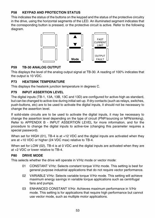
P58 KEYPAD AND PROTECTION STATUSThisindicatesthestatusofthebuttonsonthekeypadandthestatusoftheprotectivecircuitryinthedrive,usingthehorizontalsegmentsoftheLED .Anilluminatedsegmentindicatesthatthecorrespondingbuttonispressed,ortheprotectivecircuitisactive .Refertothefollowingdiagram .
FASTCURRENT
LIMIT
ModeOUTPUTFAULT
s
t
P59 TB-30 ANALOG OUTPUTThisdisplaystheleveloftheanalogoutputsignalatTB-30 .Areadingof100%indicatesthattheoutputis10VDC .
P73 HEATSINK TEMPERATUREThisdisplaystheheatsinkjunctiontemperatureindegreesC .
P79 INPUT ASSERTION LEVELThedigitalinputs(TB-1,13A,13B,13Cand13D)areconfiguredforactive-highasstandard,butcanbechangedtoactive-lowduringinitialset-up .Ifdrycontacts(suchasrelays,switches,push-buttons,etc)aretobeusedtoactivatethedigitalinputs,itshouldnotbenecessarytochangetheassertionlevel .
If solid-state circuitsare tobeused toactivate thedigital inputs, itmaybenecessary tochangetheassertionleveldependingonthetypeofcircuit(PNP/sourcingorNPN/sinking) .Refer to APPENDIX B - INPUT ASSERTION LEVEL for more information, and for theprocedure to change the digital inputs to active-low (changing this parameter requires aspecialpassword) .
WhensetforHIGH(01),TB-4isat+12VDCandthedigitalinputsareactivatedwhentheyareat+10VDCorhigher(24VDCmax)relativetoTB-4 .
WhensetforLOW(02),TB-4isat0VDCandthedigitalinputsareactivatedwhentheyareat+2VDCorlowerrelativetoTB-4 .
P80 DRIVE MODEThisselectswhetherthedrivewilloperateinV/Hzmodeorvectormode:
01 CONSTANTV/Hz:SelectsconstanttorqueV/Hzmode .Thissettingisbestforgeneralpurposeindustrialapplicationsthatdonotrequirevectorperformance .
02 VARIABLEV/Hz:SelectsvariabletorqueV/Hzmode .Thissettingwillachievemaximumenergysavingsinvariabletorqueapplicationssuchascentrifugalfansandpumps .
03 ENHANCEDCONSTANTV/Hz:AchievesmaximumperformanceinV/Hzmode .Thissettingisforapplicationsthatrequirehighperformancebutcannotusevectormode,suchasmultiplemotorapplications .
53
04 ENHANCEDVARIABLEV/Hz:Achievesmaximumperformanceforvariabletorqueapplications .Thissettingmayberequiredforhighinertiafanapplicationsthatrequirefastaccelerationanddeceleration .
05 VECTORSPEED:Selectsvectorspeedmode .Thissettingachievesmaximumperformanceforspeedcontrol .
06 VECTORTORQUE:Selectsvectortorquemode .Thissettingisforapplicationswheretorqueneedstobecontrolledratherthanspeed .
NOTE
• Ifsetting01or02isselectedallparametersabove80willbehidden .Ifsetting03or04isselectedparameters84,85andallparametersabove87willbehidden .
• If setting 03-06 is selected the AUTO CALIBRATION (Parameter 81)function must be performed and the appropriate motor characteristicparametersmustbeprogrammedproperly .
• Ifsetting06isselectedtheavailablesettingsinParameter05-STANDARDREFERENCE SOURCE change . Setting 02 (normally PRESET #1),becomesthesameassetting01(KEYPAD) .
P81 AUTO CALIBRATIONThis is used in the ENHANCED V/Hz and VECTOR modes to measure certain motorcharacteristics toachievemaximummotorperformance .Select setting01 toperform thecalibration cycle on the next start command . Setting 02 cannot be selected unless thecalibrationcyclehasalreadybeencompleted .
00 CALIBRATIONNOTDONE:DrivecannotbeoperatedinVECTORmodeifthisparametervalueis00 .
01 CALIBRATIONCYCLEENABLED:Calibrationwilloccuronthenextstartcommandandwilltakeabout40secondstocomplete .Oncethecalibrationcycleissuccessfullycompleted,thisparameterwilldisplay"02"toindicatethatthedrivecanruninvectormode .
02 CALIBRATIONCOMPLETE:Thedrivecanbeoperatedinvectormode .
NOTE
PriortoperformingtheAUTOCALIBRATION,Parameters85-88and91mustbesetproperlybasedon themotordata .Refer toAppendixB -VECTORMODEformoreinformation .
P82 CURRENT LOOP P GAINNormally, this parameter should not require adjustment . In special cases, however, itmayneed tobeadjusted tooptimizeperformance .Donotchange thisparameterwithoutconsultingLenze-ACTech .
54
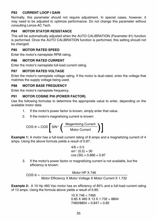
P83 CURRENT LOOP I GAINNormally, this parameter should not require adjustment . In special cases, however, itmayneed tobeadjusted tooptimizeperformance .Donotchange thisparameterwithoutconsultingLenze-ACTech .
P84 MOTOR STATOR RESISTANCEThiswillbeautomaticallyadjustedwhentheAUTOCALIBRATION(Parameter81)functionisperformed .OncetheAUTOCALIBRATIONfunctionisperformed,thissettingshouldnotbechanged .
P85 MOTOR RATED SPEEDEnterthemotor'snameplateRPMrating .
P86 MOTOR RATED CURRENTEnterthemotor'snameplatefull-loadcurrentrating .
P87 MOTOR RATED VOLTAGEEnterthemotor'snameplatevoltagerating .Ifthemotorisdual-rated,enterthevoltagethatmatchesthesupplyvoltagebeingused .
P88 MOTOR BASE FREQUENCYEnterthemotor'snameplatefrequency .
P91 MOTOR COSINE PHI (POWER FACTOR)Usethe followingformulas todeterminetheappropriatevalue toenter,dependingontheavailablemotordata:
1 . Ifthemotor'spowerfactorisknown,simplyenterthatvalue .
2 . Ifthemotor'smagnetizingcurrentisknown:
COSF=COS [SIN-1( MagentizingCurrent )]MotorCurrent
Example 1:Amotorhasafull-loadcurrentratingof8ampsandamagnetizingcurrentof4amps .Usingtheaboveformulayieldsaresultof0 .87:
4/8=0 .5 sin-1(0 .5)=30 cos(30)=0 .866=0 .87
3 . Ifthemotor'spowerfactorormagnetizingcurrentisnotavailable,buttheefficiencyisknown:
COSF=MotorHPX746
MotorEfficiencyXMotorVoltageXMotorCurrentX1 .732
Example 2:A10Hp460Vacmotorhasanefficiencyof85%andafull-loadcurrentratingof13amps .Usingtheformulaaboveyieldsaresultof0 .85:
10X746=7460 0 .85X460X13X1 .732=8804 7460/8804=0 .847=0 .85
55

P92 MOTOR INDUCTANCEThiswillbeautomaticallyadjustedwhentheAUTOCALIBRATION(Parameter81)functionisperformed .OncetheAUTOCALIBRATIONfunctionisperformed,thissettingshouldnotbechanged .
P93 TORQUE LIMITWhenthedriveisinVECTORTORQUEmode(refertoParameter80)thisparametersetsthemaximumoutputtorque .Inthismode,thetorquereferencesourcecanbethekeypad(sandtbuttons),a0-10VDCsignal,ora4-20mAsignal(presetspeedscannotbeusedastorquereferences) .Thedrivewillrunatthefastestspeedpossibletodeliverthedesiredtorque .
P94 DRIVE PERSONALITYThisparameterwilldisplaythedrive's"personality"byindicatingthevoltageandHPrating .Thedisplayedvalueis3digits .
Thefirstdigitindicatesthevoltage(2=208/240Vac;4=400/480Vac,5=480/590Vac) .Ifthedriveisratedforsingle-phaseandthree-phaseinput(modelnumbersthatendin"Y"),theleftbottomdecimalpointwillilluminatetodistinguishitfromathree-phaseonlymodel .Refertotheexamplesherein .
ThesecondandthirddigitsindicatetheHPrating(01=1HP,02=2HP,etc) .Ifthedrive'sHPratingis0 .5,1 .5,or7 .5,thebottomrightdecimalpointwillbeilluminated .Refertotheexamplesherein .
Example 1:Thedisplayedvalueis"405" .The"4"indicatesthatthedriveisa400/480Vacmodel,andthe"05"indicatesthatitisrated5HP .
Example 2: The displayed value is "2 .1 .5" . The "2" with the bottom left decimal pointilluminatedindicatesthatthedriveisa208/240Vacmodelthatcanacceptsingle-phaseorthree-phaseinput .The"1 .5"indicatesthatthedriveisrated1 .5HP .
Example1 Example2
NOTE
IfthepersonalitystoredontheEPMdoesnotmatchthedrivemodel,thedrivemaytripintoa"bF"fault .RefertoSection13 .2 .
P95 MOTOR CURRENTThisdisplaysthecurrent(inamps)thatthemotorisdrawing .
P96 MOTOR TORQUEThisdisplaysthetorque(in%)thatthemotorisgenerating .
56
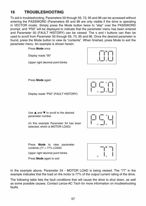
16 TROUBLESHOOTING Toaidintroubleshooting,Parameters50through59,73,95and96canbeaccessedwithoutenteringthePASSWORD(Parameters95and96areonlyvisible if thedrive isoperatingin VECTOR mode) . Simply press the Mode button twice to “skip” over the PASSWORDprompt,and“P50”willbedisplayedtoindicatethattheparametermenuhasbeenenteredand Parameter 50 (FAULT HISTORY) can be viewed . The s and t buttons can then beusedtoscrollfromParameter50through59,73,95and96 .Oncethedesiredparameterisfound,presstheModebuttontoviewits“contents” .Whenfinished,pressModetoexittheparametermenu .Anexampleisshownherein .
PressModeonce
Upperrightdecimalpointblinks
Displayreads"00"
PressModeagain
Displayreads"P50"(FAULTHISTORY)
Usesandttoscrolltothedesiredparameternumber
Press Mode to view parametercontents(77=77%LOAD)
PressModeagaintoexit
Upperrightdecimalpointblinks
(In this example Parameter 54 has beenselected,whichisMOTORLOAD)
In the example above, Parameter 54 - MOTOR LOAD is being viewed . The “77” in theexampleindicatesthattheloadonthemotoris77%oftheoutputcurrentratingofthedrive .
Thefollowingtableliststhefaultconditionsthatwillcausethedrivetoshutdown,aswellassomepossiblecauses .ContactLenze-ACTechformoreinformationontroubleshootingfaults .
57
FAULT MESSAGES
FAULT DESCRIPTION & POSSIBLE CAUSES
Ad A/Dconverteroffseterror-consultfactory .
AF HighTemperatureFault:Ambienttemperatureistoohigh;Coolingfanhasfailed(ifequipped) .
AL,A1-A4 Assertionlevelfaults .RefertosectionB .5inAppendixB .
bFPersonalityFault:Thepersonality(P94)storedontheEPMdoesnotmatchthedrivemodel .RefertoSection13 .2 .
CFControlFault:AblankEPM,oranEPMwithcorrupteddatahasbeeninstalled .PerformafactoryresetusingParameter48-PROGRAMSELECTION .
cFIncompatibilityFault:AnEPMwithanincompatibleparameterversionhasbeeninstalled .EitherexchangetheEPM,orperformafactoryreset(Parameter48)tochangetheparameterversionoftheEPMtomatchtheparameterversionofthedrive .
dFDynamicBrakingFault:Thedrivehassensedthatthedynamicbrakingresistorsareoverheatingandshutsdowntoprotecttheresistors .
EFExternalFault:TB-13A,TB-13C,and/orTB-13DissetasanExternalFaultinputandoneofthoseterminalsisopenwithrespecttoTB-4 .RefertoParameters10,12,and/or49 .
GF DataFault:UserdataandOEMdefaultsintheEPMarecorrupted .
HFHighDCBusVoltageFault:Linevoltageistoohigh;Decelerationrateistoofast;Overhaulingload .Forfastdecelerationoroverhaulingloads,dynamicbrakingmayberequired .
ILIllegalSetup:TB-13AandTB-13DarebothsetforSTARTFORWARD,orTB-13AissetforRUNREVERSEandTB-13DissetforSTARTFORWARD .
JF SerialFault:Thewatchdogtimerhastimedout,indicatingthattheseriallinkhasbeenlost .
LF LowDCBusVoltageFault:Linevoltageistoolow .
OFOutputTransistorFault:Phasetophaseorphasetogroundshortcircuitontheoutput;Failedoutputtransistor;Boostsettingsaretoohigh;Accelerationrateistoofast .
PFCurrentOverloadFault:VFDisundersizedfortheapplication;Mechanicalproblemwiththedrivenequipment .
rF FlyingRestartFault:Drivewasunabletosynchronizewiththemotorduringtherestartattempt .
SF Single-phaseFault:Single-phaseinputpowerhasbeenappliedtoathree-phasedrive .
UFStartFault:Startcommandwaspresentwhenthedrivewaspoweredup .Mustwait2secondsafterpower-uptoapplyStartcommandifSTARTMETHODissettoNORMAL .
F1 EPMFault:TheEPMismissingordamaged .
F2-F9,Fo InternalFaults:Thecontrolboardhassensedaproblem-consultfactory .
ToclearafaultissueaSTOPcommand,eitherontheterminalstriporusingtheSTOPbuttonontheoptionalremotekeypad .Thefaultwillonlycleariftheconditionthatcausedthefaulthaspassed .Forexample,ifthedrivetripsonaLOWDCBUSVOLTAGEFAULT(LF)duetolowinputvoltage,thefaultcannotbecleareduntiltheinputvoltagereturnstoanormallevel .
If thedrive isprogrammed toautomatically restart after a fault (Parameter03), thedrivewillattempttorestartthreetimesafterafault(thedrivewillnotrestartafterAd,AL,A1-A4,bF,CF,cF,GF,IL,F1,F2-F9,orFofaults) .Ifall threerestartattemptsareunsuccessful,thedrivewilltripintoFAULTLOCKOUT(LC),whichrequiresamanualresetasdescribedabove .
58
17 TCF DISPLAY MESSAGES ThefollowingdescribesthevariousdisplaysandmessagesthatcanappearontheTCFdrive .
17 .1 SPEED/TORQUEDISPLAY
If the drive is in a STOP state (indicated by "- - -" on the display), and the commandedspeed/torque is changedusing the keypad (s andt buttons), thedisplaywill show thecommandedspeed/torque,andaftera fewseconds itwillbegin toalternatebetween thecommandedspeed/torquevalueand"---" .IftheModebuttonispressed,thedisplaywillstopalternatingandshow"---"only .
WhenthedriveisgivenaSTARTcommand,thedisplayedspeedwillstartincreasingasthedriveacceleratesuptothecommandedspeed/torque .Ifthecommandedspeed/torquevalueischangedwhilethedriveisrunning,thedisplaywillshowthecommandedvaluewhileitisbeingchanged,butthenitwilldisplaytheactualspeedasthedriverampsupordowntothenewcommandedvalue .
NOTE
• Whenthedriveisrunninginthereversedirection,theupperdecimalpointonthedisplaywillbeilluminated .
• InVECTORTORQUEmode(refertoParameter80),thetorquereferencedisplaywillhavethebottomtwodecimalpointsilluminatedtodistinguishitfromtheactualspeeddisplay .
59
17 .2 CHANGINGTHESPEEDREFERENCESOURCE
Whenthespeed/torquesourceischangedwhilethedriveisrunning,thedisplaywillflashthemessageforthenewspeed/torquesourcetoindicatethatthenewsourceisactive .Also,ifthedriveisbeingcontrolledfromaspeed/torquesourceotherthanthesandtbuttons(0-10VDC,4-20mA,etc),andoneofthesortbuttonsispressed,thedisplaywillflashthepresentspeedsourcemessagetoindicatethatthesandtbuttonsareinvalid .
NOTE
If the drive is in a STOP state, and the speed reference is changed, thedisplaywillnotshowthemessageforthenewreferencesource .Itwillonlydosowhenthedriveisrunning .
Example 1:Thedrive is runningandthepresentspeedsource is thekeypad .TB-13A isprogrammed toselecta4-20mAsignalas thespeedsource .WhenTB-13A isclosed toTB-2,thedisplaywillflash“EI”toindicatethatthespeedsourcehaschangedtothe4-20mAsignal .IfthecontactbetweenTB-13AandTB-2isopened,thedisplaywillflash“CP”toindicatethatthespeedsourcehaschangedbacktothes andtbuttons .
Example 2:Thespeedsource isa0-10VDCsignal . If thesortbutton ispushed, thedisplaywillflash“EU”toindicatethatthepresentspeedsourceisthe0-10VDCsignalandthatthesandtbuttonsareinvalid .
Refertothetablebelowforthepossiblespeed/torquereferencesourcedisplays:
SPEED SOURCE DISPLAYS
DISPLAY DESCRIPTION
CP/tCPCONTROL
PADSpeed/torqueissetusingthesandtbuttonsonthefrontofthedrive .
EI/tEIEXTERNALCURRENT
Speed/torquesourceisa4-20mAsignalwiredtoTB-25andTB-2 .
EU/tEUEXTERNALVOLTAGE
Speed/torquesourceisa0-10VDCsignalwiredtoTB-5andTB-2 .
JG JOGThedriveisinJogmode,andthespeedissetbyPresetSpeed#2(Parameter32) .
OP MOP(MotorOperatedPot)ContactswiredtoTB-13BandTB-13Careusedtoincreaseanddecreasethedrivespeed .
Pr1-Pr7PRESET
SPEEDS#1-7SpeedissetbytheindicatedPresetSpeed(Parameters31-37) .
NOTEThe speed source displays will flash when the speed reference source ischangedwhilethedriveisrunningtoindicatethatthenewspeedreferencesourceisactive .
60
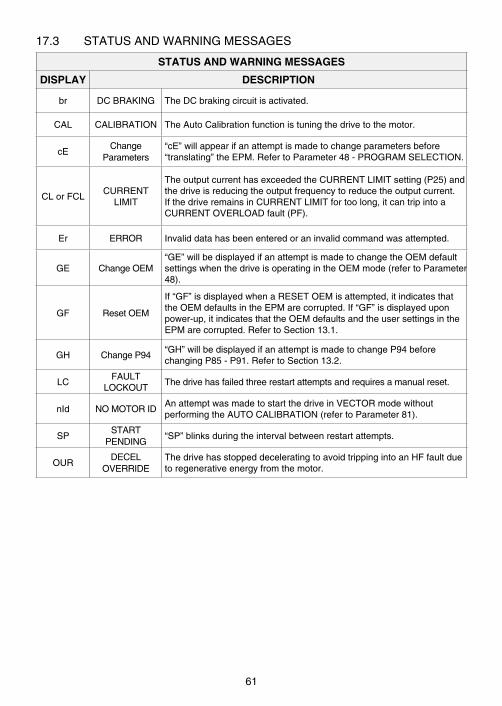
17 .3 STATUSANDWARNINGMESSAGES
STATUS AND WARNING MESSAGES
DISPLAY DESCRIPTION
br DCBRAKING TheDCbrakingcircuitisactivated .
CAL CALIBRATION TheAutoCalibrationfunctionistuningthedrivetothemotor .
cEChange
Parameters“cE”willappearifanattemptismadetochangeparametersbefore“translating”theEPM .RefertoParameter48-PROGRAMSELECTION .
CLorFCLCURRENT
LIMIT
TheoutputcurrenthasexceededtheCURRENTLIMITsetting(P25)andthedriveisreducingtheoutputfrequencytoreducetheoutputcurrent .IfthedriveremainsinCURRENTLIMITfortoolong,itcantripintoaCURRENTOVERLOADfault(PF) .
Er ERROR Invaliddatahasbeenenteredoraninvalidcommandwasattempted .
GE ChangeOEM“GE”willbedisplayedifanattemptismadetochangetheOEMdefaultsettingswhenthedriveisoperatingintheOEMmode(refertoParameter48) .
GF ResetOEM
If“GF”isdisplayedwhenaRESETOEMisattempted,itindicatesthattheOEMdefaultsintheEPMarecorrupted .If“GF”isdisplayeduponpower-up,itindicatesthattheOEMdefaultsandtheusersettingsintheEPMarecorrupted .RefertoSection13 .1 .
GH ChangeP94“GH”willbedisplayedifanattemptismadetochangeP94beforechangingP85-P91 .RefertoSection13 .2 .
LCFAULT
LOCKOUTThedrivehasfailedthreerestartattemptsandrequiresamanualreset .
nId NOMOTORIDAnattemptwasmadetostartthedriveinVECTORmodewithoutperformingtheAUTOCALIBRATION(refertoParameter81) .
SPSTART
PENDING“SP”blinksduringtheintervalbetweenrestartattempts .
OURDECEL
OVERRIDEThedrivehasstoppeddeceleratingtoavoidtrippingintoanHFfaultduetoregenerativeenergyfromthemotor .
61

A APPENDIX - VECTOR MODEA.1 GENERALTheTCFSeriesisasensorlessvectordrivethatcanbeoperatedinspeedortorquemode,aswellasV/Hzmode .Operation inVectormoderesults ingreater torque(200%startingtorqueandfulltorquedownto1Hz)andmoreprecisespeedregulationthanV/Hzmode .However,therearecaseswhereVectormodeisnotrecommended:
1 . Multiplemotorapplications .
2 . Whererequiredmotordataisnotavailable .
3 . WhererunninginVectormodecausesunstablemotoroperation .
Inthesecases, it isrecommendedthat thedrivebeoperated inV/HzmodeorEnhancedV/Hzmode(refertoParameter80-DRIVEMODE) .
A.2 CONFIGURING THE TCF FOR VECTOR MODE1 . ConnectthedrivetothemotoraccordingtothediagraminSection9-TCF
POWERWIRINGDIAGRAM .
2 . Applypowertothedrive .
3 . SetParameter80-DRIVEMODEtoVECTORSPEED(05)orVECTORTORQUE(06),dependingonwhetheritisdesiredtocontrolspeedortorque .
4 . SetParameters85-88and91accordingtothemotor'snameplatedata .
5 . SetParameter81-AUTOCALIBRATIONtoCALIBRATIONCYCLEENABLED(01) .Thedrive'sdisplaywillalternatebetween"CAL"and"---" .
6 . Makesurethemotoriscold(rotorandwindingsareatroomtemperatureof20°to25°C),andgivethedriveaSTARTcommandusingoneoftheStart/StopcircuitsshowninSection11-TCFCONTROLWIRINGDIAGRAMS .Thedrive'sdisplayshouldindicate"CAL"forabout40secondswhilethecalibrationprocedureisperformed .Oncethecalibrationisdone,thedisplaywillshow"---"toindicatethatitisstopped .Thedriveisnowreadytobeoperated .GivethedriveanotherSTARTcommandtoactuallystartthemotor .
NOTE
• IfthemotorishotwhentheAUTOCALIBRATIONisperformed,thedrivewillnotbeabletoachievemaximumperformance .
• InVECTORSPEEDorVECTORTORQUEmode,ifanattemptismadetostartthedrivebeforeperformingtheAUTOCALIBRATION,thedrivewilldisplay"nId",andthemotorwillnotoperate .
62
A.3 ENHANCED V/Hz MODEIncaseswhereVectormode isnotappropriate, theTCFSeriesdrivecanbeoperated inEnhancedV/HzmodetoachievemaximumV/Hzperformance .UsethefollowingproceduretoconfigurethedriveforEnhancedV/Hzmode:
1 . ConnectthedrivetothemotoraccordingtothediagraminSection9-TCFPOWERWIRINGDIAGRAM .
2 . Applypowertothedrive .
3 . SetParameter80-DRIVEMODEtoENHANCEDCONSTANTV/Hz(03)orENHANCEDVARIABLEV/Hz(04),dependingonwhethertheapplicationisconstanttorqueorvariabletorque .IftheapplicationisacentrifugalfanorpumpselectENHANCEDVARIABLEV/Hz(04) .Otherwise,selectENHANCEDCONSTANTV/Hz(03) .
4 . SetParameter86and87accordingtothemotor'snameplatedata .
5 . SetParameter81-AUTOCALIBRATIONtoCALIBRATIONCYCLEENABLED(01) .Thedrive'sdisplaywillalternatebetween"CAL"and"---" .
6 . Makesurethemotoriscold(rotorandwindingsareatroomtemperatureof20°to25°C),andgivethedriveaSTARTcommandusingoneoftheStart/StopcircuitsshowninSection11-TCFCONTROLWIRINGDIAGRAMS .Thedrive'sdisplayshouldindicate"CAL"forabout40secondswhilethecalibrationprocedureisperformed .Oncethecalibrationisdone,thedisplaywillshow"---"toindicatethatitisstopped .Thedriveisnowreadytobeoperated .GivethedriveanotherSTARTcommandtoactuallystartthemotor .
63
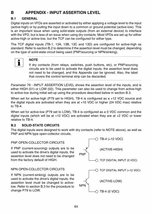
B APPENDIX - INPUT ASSERTION LEVELB.1 GENERALDigitalinputsonVFDsareassertedoractivatedbyeitherapplyingavoltageleveltotheinput(active-high)orbypullingtheinputdowntoacommonorgroundpotential(active-low) .Thisisanimportantissuewhenusingsolid-stateoutputs(fromanexternaldevice)tointerfacewiththeVFD,butislessofanissuewhenusingdrycontacts .MostVFDsaresetupforeitheractive-highoractive-low,buttheTCFcanbeconfiguredforeithertype .
TheTCFdigital inputs (TB-1, 13A, 13B, 13Cand13D)are configured for active-highasstandard .RefertosectionB .2todetermineiftheassertionlevelmustbechanged,dependingonthetypeofsolid-statecircuitbeingused(PNP/sourcingorNPN/sinking) .
NOTE
Ifdrycontacts (from relays,switches,pushbuttons,etc),orPNP/sourcingcircuitsaretobeusedtoactivatethedigitalinputs,theassertionleveldoesnotneedtobechanged,andthisAppendixcanbeignored .Also,thelabelthatcoversthecontrolterminalstripcanbediscarded .
Parameter79-INPUTASSERTIONLEVELshowstheassertionleveloftheinputs,andiseitherHIGH(01)orLOW(02) .Thisparametercanalsobeusedtochangefromactive-hightoactive-lowduringinitialset-upusingtheproceduredescribedbelowinsectionB .3 .
Whensetforactive-high(P79settoHIGH),TB-4isconfiguredasa+12VDCsourceandthedigitalinputsareactivatedwhentheyareat+10VDCorhigher(24VDCmax)relativetoTB-4 .
Whensetforactive-low(P79settoLOW),TB-4isconfiguredasa0VDCcommonandthedigital inputs(whichwillbeat+12VDC)areactivatedwhentheyareat+2VDCor lowerrelativetoTB-4 .
B.2 SOLID-STATE CIRCUITSThedigitalinputsweredesignedtoworkwithdrycontacts(refertoNOTEabove),aswellasPNPandNPNtypeopen-collectorcircuits .
PNPOPEN-COLLECTORCIRCUITS
IfPNP (current-sourcing)outputsare tobeusedtoactivatethedrive'sdigitalinputs,theassertionleveldoesnotneedtobechangedfromthefactorydefaultofHIGH .
NPNOPEN-COLLECTORCIRCUITS
If NPN (current-sinking) outputs are to beusedtoactivatethedrive'sdigitalinputs,theassertion level must be changed to active-low .RefertosectionB .3fortheproceduretochangeP79toLOW .
TB-4(+12VDC)
TCFDIGITALINPUT(0VDC)
(ACTIVE-HIGH)
PNP
TB-4(0VDC)
TCFDIGITALINPUT(+12VDC)
(ACTIVE-LOW)NPN
64
B.3 PROCEDURE FOR CHANGING INPUTS FROM ACTIVE-HIGH TO ACTIVE-LOWIfitisnecessarytochangetheassertionlevelfromactive-hightoactive-low,itcanbedonevia procedure 3 .1 'Using the Programming Buttons on the Drive' or 3 .2 'Using the EPMProgrammer' .
WARNING!
Changing the assertion level of the digital inputs without removing orreconfiguring thecontrolwiringcancausethemotor tostartunexpectedly,resultinginequipmentdamageand/orinjurytopersonnel!Besuretoremoveallcontrolwiringfromthedrive'sterminalstrippriortochangingtheasserionlevel .
NOTE:
Once the followingprocedure isperformedand the inputsarechanged toactive-low,theycannotbechangedbacktoactive-highwiththisprocedure .DO NOT CHANGE THE ASSERTION LEVEL UNLESS YOU ARE SUREITISNECESSARYFORYOURSYSTEM!Iftheprocedureisperformedbymistake,anditisnecessarytochangetheassertionlevelbacktoactive-high,pleasecontactLenze-ACTech .
B.3.1 PROCEDURE #1 - USING THE PROGRAMMING BUTTONS ON THE DRIVE1 . Removeallcontrolwiringfromtheterminalstripofthedrive .
2 . EntertheprogrammingmodeasnormalandgotoParameter79-INPUTASSERTIONLEVEL .
3 . PressModetodisplaythepresentsetting(shouldbe"01"foractive-high) .
4 . Pressthesbutton .Thedisplaywillflash"PAS"andthen"00",indicatingthatthespecialpasswordmustbeenteredfirstinordertochangethesetting .
5 . Usethesandtbuttonstoscrolltothepasswordvalueindicatedonthelabelthatcoversthedrive'scontrolterminalstrip,andpressMode .
6 . ThesettingofP79shouldnowindicate"02"foractive-low .
65
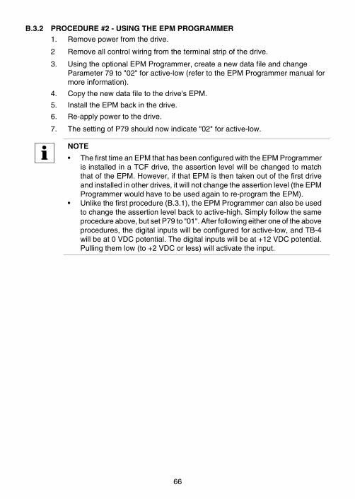
B.3.2 PROCEDURE #2 - USING THE EPM PROGRAMMER1 . Removepowerfromthedrive .
2 Removeallcontrolwiringfromtheterminalstripofthedrive .
3 . UsingtheoptionalEPMProgrammer,createanewdatafileandchangeParameter79to"02"foractive-low(refertotheEPMProgrammermanualformoreinformation) .
4 . Copythenewdatafiletothedrive'sEPM .
5 . InstalltheEPMbackinthedrive .
6 . Re-applypowertothedrive .
7 . ThesettingofP79shouldnowindicate"02"foractive-low .
NOTE
• ThefirsttimeanEPMthathasbeenconfiguredwiththeEPMProgrammerisinstalledinaTCFdrive,theassertionlevelwillbechangedtomatchthatoftheEPM .However,ifthatEPMisthentakenoutofthefirstdriveandinstalledinotherdrives,itwillnotchangetheassertionlevel(theEPMProgrammerwouldhavetobeusedagaintore-programtheEPM) .
• Unlikethefirstprocedure(B .3 .1),theEPMProgrammercanalsobeusedtochangetheassertionlevelbacktoactive-high .Simplyfollowthesameprocedureabove,butsetP79to"01" .Afterfollowingeitheroneoftheaboveprocedures,thedigitalinputswillbeconfiguredforactive-low,andTB-4willbeat0VDCpotential .Thedigitalinputswillbeat+12VDCpotential .Pullingthemlow(to+2VDCorless)willactivatetheinput .
66
B.4 ASSERTION LEVEL AND THE EPMTheTCFdrivewillstorethesettingofParameter79-INPUTASSERTIONLEVELontheEPM (like it does with all of the other parameters), but it will also store this informationinternallyasasafeguardagainsttheassertionlevelbeingchangedaccidentallybyswappingEPMs .
TheP79settingstoredontheEPMmustmatchtheinternallystoredsettingorthedrivewilltripintoan"A1"faultandwillnotoperate .Therefore,ifanEPMwithadifferentP79settingisinstalledinadrive,thedisplaywillshowthe"A1"faultandthedrivewillnotoperate .TheonlyexceptiontothisisiftheEPMwasjustprogrammedusingtheEPMProgrammer,anditwasbeinginstalledinadriveforthefirsttime .Inthiscase,thedrive'sinternalassertionlevelsettingwillchangetomatchtheEPM,asdescribedinNOTE1insectionB .3 .2,andnofaultwouldoccur .
WARNING!
Changing the assertion level of the digital inputs without reconfiguringthe control wiring can cause the motor to start unexpectedly, resulting inequipmentdamageand/orinjurytopersonnel!Besurethecontrolwiringiscorrectfortheselectedassertionlevel .
An"A1"faultcanbeclearedbyoneofthefollowingmethods:
1 . PerformafactoryresetofthedriveusingParameter48-PROGRAMSELECTION .ThiswillchangetheassertionlevelsettingintheEPMtomatchtheinternallystoredsetting .
2 . PowerdownthedriveandinstallanEPMthathasthesameassertionlevelsettingastheinternalsetting .
3 . PowerdownthedriveandinstallanEPMthathasjustbeenprogrammedwiththeEPMProgrammer .
4 . ChangeP79tomatchtheassertionlevelontheEPM .Iftheassertionlevelisactive-low,andneedstobesetbacktoactive-high,pleasecontactLenze-ACTech .
67
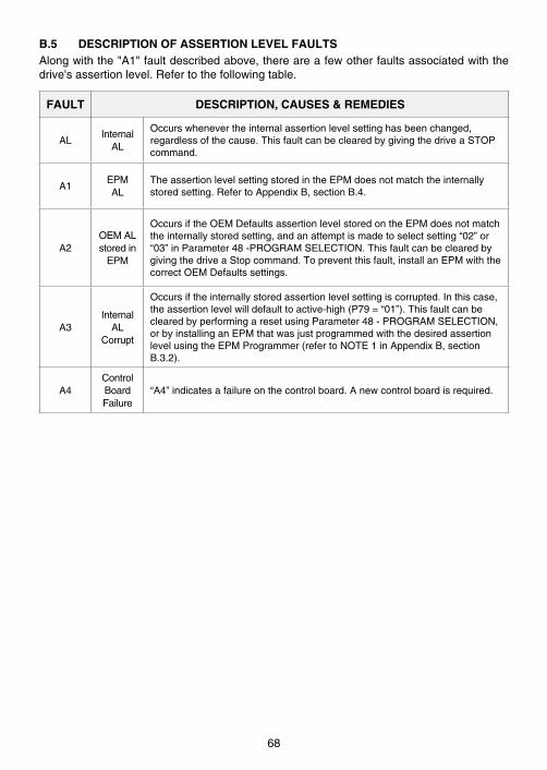
B.5 DESCRIPTION OF ASSERTION LEVEL FAULTSAlongwiththe"A1"faultdescribedabove,thereareafewotherfaultsassociatedwiththedrive'sassertionlevel .Refertothefollowingtable .
FAULT DESCRIPTION, CAUSES & REMEDIES
ALInternal
AL
Occurswhenevertheinternalassertionlevelsettinghasbeenchanged,regardlessofthecause .ThisfaultcanbeclearedbygivingthedriveaSTOPcommand .
A1EPMAL
TheassertionlevelsettingstoredintheEPMdoesnotmatchtheinternallystoredsetting .RefertoAppendixB,sectionB .4 .
A2OEMALstoredin
EPM
OccursiftheOEMDefaultsassertionlevelstoredontheEPMdoesnotmatchtheinternallystoredsetting,andanattemptismadetoselectsetting“02”or“03”inParameter48-PROGRAMSELECTION .ThisfaultcanbeclearedbygivingthedriveaStopcommand .Topreventthisfault,installanEPMwiththecorrectOEMDefaultssettings .
A3Internal
ALCorrupt
Occursiftheinternallystoredassertionlevelsettingiscorrupted .Inthiscase,theassertionlevelwilldefaulttoactive-high(P79=“01”) .ThisfaultcanbeclearedbyperformingaresetusingParameter48-PROGRAMSELECTION,orbyinstallinganEPMthatwasjustprogrammedwiththedesiredassertionlevelusingtheEPMProgrammer(refertoNOTE1inAppendixB,sectionB .3 .2) .
A4ControlBoardFailure
“A4”indicatesafailureonthecontrolboard .Anewcontrolboardisrequired .
68

NOTES
69

NOTES
70


Lenze AC Tech Corporation630 Douglas Street • Uxbridge, MA 01569 • USASales: 800 217-9100 • Service: 508 278-9100
www.lenzeamericas.com
Document:TF01D-e2