Embed Size (px)
Citation preview

Operating Instructions
EDBMF2141N\e
Fieldbus module type 2141LON (Local Operating Network)
ÄN\eä
Service
LON
L
24V DC FTT
2141

qÜÉëÉ léÉê~íáåÖ fåëíêìÅíáçåë ~êÉ î~äáÇ Ñçê ÑáÉäÇÄìë ãçÇìäÉë ïáíÜ íÜÉ ÑçääçïáåÖ å~ãÉéä~íÉëW
2141 IB. 0x. 0x. LON
få ÅçååÉÅíáçå ïáíÜ íÜÉ ìåáí ëÉêáÉë ~ë Ñêçã íÜÉ å~ãÉéä~íÉ Ç~í~W820X E./C. 2x. 1x. (8201 - 8204)
821X E./C. 2x. 2x. (8211 - 8218)
822X E. 1x. 1x. (8221 - 8227)
824X E.C. 1x. 1x. (8241 - 8246)
82EVxxxxxBxxxXX Vx 1x 8200 vector
EPL 10200 I.T. 1x. 1x. (Drive PLC)
93XX E./C. 2x. 1x. (9321 - 9333)
93XX E./C. I.T. 2x. 1x. (9300 Servo PLC)
Type
Design:E = Built-in unit IP20IB = Module
Hardware version and index
Software version and index
Variant
Explanation
Important:
These Operating Instructions are only valid together with the corresponding Operating Instruc-tions for the 82XX, 8200 vector, 93XX and 9300 Servo PLC and Drive PLC.
What is new?
Material no. Version Important Contents455968 1.0 08/02 TD02 1st edition
E 2002 Lenze Drive Systems GmbH
No part of these Instructions must be copied or given to third parties without written approval of Lenze Drive Systems GmbH.
All information given in this documentation have been checked for compliance with the hardware and software described. Nevertheless, deviations andmistakes cannot be ruled out. We do not take any responsibility or liability for damages which might possibly occur. Necessary corrections will be includedin the next edition.

Contents
iL BA2141 EN 1.0
1 Preface and general information 1-1. . . . . . . . . . . . . . . . . . . . . . . . . . . . . . . . . . . . . . . . . . .
1.1 How to use these Operating Instructions 1-1. . . . . . . . . . . . . . . . . . . . . . . . . . . . . . . . . . . . . . . . . . . . . . . .1.1.1 Terminology used 1-1. . . . . . . . . . . . . . . . . . . . . . . . . . . . . . . . . . . . . . . . . . . . . . . . . . . . . . . . .
1.2 Packing list 1-1. . . . . . . . . . . . . . . . . . . . . . . . . . . . . . . . . . . . . . . . . . . . . . . . . . . . . . . . . . . . . . . . . . . . .1.2.1 Legal regulations 1-2. . . . . . . . . . . . . . . . . . . . . . . . . . . . . . . . . . . . . . . . . . . . . . . . . . . . . . . . . .
2 Safety information 2-1. . . . . . . . . . . . . . . . . . . . . . . . . . . . . . . . . . . . . . . . . . . . . . . . . . . . . .
2.1 Persons responsible for the safety 2-1. . . . . . . . . . . . . . . . . . . . . . . . . . . . . . . . . . . . . . . . . . . . . . . . . . . .
2.2 General safety information 2-1. . . . . . . . . . . . . . . . . . . . . . . . . . . . . . . . . . . . . . . . . . . . . . . . . . . . . . . . . .
2.3 Layout of the safety information 2-2. . . . . . . . . . . . . . . . . . . . . . . . . . . . . . . . . . . . . . . . . . . . . . . . . . . . . .
3 Technical data 3-1. . . . . . . . . . . . . . . . . . . . . . . . . . . . . . . . . . . . . . . . . . . . . . . . . . . . . . . . .
3.1 Features of the 2141 fieldbus module 3-1. . . . . . . . . . . . . . . . . . . . . . . . . . . . . . . . . . . . . . . . . . . . . . . . . .
3.2 General data / application conditions 3-1. . . . . . . . . . . . . . . . . . . . . . . . . . . . . . . . . . . . . . . . . . . . . . . . . .
3.3 Rated data 3-2. . . . . . . . . . . . . . . . . . . . . . . . . . . . . . . . . . . . . . . . . . . . . . . . . . . . . . . . . . . . . . . . . . . . . .
3.4 Dimensions 3-2. . . . . . . . . . . . . . . . . . . . . . . . . . . . . . . . . . . . . . . . . . . . . . . . . . . . . . . . . . . . . . . . . . . . .
3.5 Communication times 3-3. . . . . . . . . . . . . . . . . . . . . . . . . . . . . . . . . . . . . . . . . . . . . . . . . . . . . . . . . . . . .3.5.1 Processing time in the basic unit 3-3. . . . . . . . . . . . . . . . . . . . . . . . . . . . . . . . . . . . . . . . . . . . . .3.5.2 Number of devices connected to the bus 3-3. . . . . . . . . . . . . . . . . . . . . . . . . . . . . . . . . . . . . . . .
4 Installation 4-1. . . . . . . . . . . . . . . . . . . . . . . . . . . . . . . . . . . . . . . . . . . . . . . . . . . . . . . . . . . .
4.1 Elements at the front of the 2141 fieldbus module 4-1. . . . . . . . . . . . . . . . . . . . . . . . . . . . . . . . . . . . . . . . .4.1.1 Connection of external voltage supply 4-2. . . . . . . . . . . . . . . . . . . . . . . . . . . . . . . . . . . . . . . . . .4.1.2 Connection for LON bus 4-2. . . . . . . . . . . . . . . . . . . . . . . . . . . . . . . . . . . . . . . . . . . . . . . . . . . . .4.1.3 Data for connection terminals 4-2. . . . . . . . . . . . . . . . . . . . . . . . . . . . . . . . . . . . . . . . . . . . . . . .
4.2 Mechanical installation 4-3. . . . . . . . . . . . . . . . . . . . . . . . . . . . . . . . . . . . . . . . . . . . . . . . . . . . . . . . . . . . .
4.3 Electrical installation 4-4. . . . . . . . . . . . . . . . . . . . . . . . . . . . . . . . . . . . . . . . . . . . . . . . . . . . . . . . . . . . . .4.3.1 Wiring to a host 4-4. . . . . . . . . . . . . . . . . . . . . . . . . . . . . . . . . . . . . . . . . . . . . . . . . . . . . . . . . . .4.3.2 Voltage supply 4-5. . . . . . . . . . . . . . . . . . . . . . . . . . . . . . . . . . . . . . . . . . . . . . . . . . . . . . . . . . . .
5 Commissioning 5-1. . . . . . . . . . . . . . . . . . . . . . . . . . . . . . . . . . . . . . . . . . . . . . . . . . . . . . . .
5.1 First switch-on 5-1. . . . . . . . . . . . . . . . . . . . . . . . . . . . . . . . . . . . . . . . . . . . . . . . . . . . . . . . . . . . . . . . . . .
5.2 Configure the controller for the communication with the 2141 fieldbus module 5-2. . . . . . . . . . . . . . . . . . . .5.2.1 Protection against uncontrolled restart 5-2. . . . . . . . . . . . . . . . . . . . . . . . . . . . . . . . . . . . . . . . . .

Contents
ii LBA2141 EN 1.0
6 Parameter setting 6-1. . . . . . . . . . . . . . . . . . . . . . . . . . . . . . . . . . . . . . . . . . . . . . . . . . . . . .
6.1 Parameter data channel configuration 6-2. . . . . . . . . . . . . . . . . . . . . . . . . . . . . . . . . . . . . . . . . . . . . . . . . .6.1.1 Parameter data 6-2. . . . . . . . . . . . . . . . . . . . . . . . . . . . . . . . . . . . . . . . . . . . . . . . . . . . . . . . . . .6.1.2 Network variable for the parameter data channel 6-3. . . . . . . . . . . . . . . . . . . . . . . . . . . . . . . . . .
6.1.2.1 Structure of network variables 6-3. . . . . . . . . . . . . . . . . . . . . . . . . . . . . . . . . . . . . .
6.2 Overview: Network variable and configuration variable 6-1. . . . . . . . . . . . . . . . . . . . . . . . . . . . . . . . . . . . .6.2.1 Overview: Node Object 6-1. . . . . . . . . . . . . . . . . . . . . . . . . . . . . . . . . . . . . . . . . . . . . . . . . . . . .6.2.2 Overview: Network variable for VSD control 6-2. . . . . . . . . . . . . . . . . . . . . . . . . . . . . . . . . . . . . .6.2.3 Overview: Network variable for AIF-CTRL control 6-2. . . . . . . . . . . . . . . . . . . . . . . . . . . . . . . . . .6.2.4 Overview: Configuration variable for VSD control 6-3. . . . . . . . . . . . . . . . . . . . . . . . . . . . . . . . . . .
6.3 Node Object 6-4. . . . . . . . . . . . . . . . . . . . . . . . . . . . . . . . . . . . . . . . . . . . . . . . . . . . . . . . . . . . . . . . . . . . .6.3.1 Inhibit / Enable all objects 6-4. . . . . . . . . . . . . . . . . . . . . . . . . . . . . . . . . . . . . . . . . . . . . . . . . . .6.3.2 Status messages 6-4. . . . . . . . . . . . . . . . . . . . . . . . . . . . . . . . . . . . . . . . . . . . . . . . . . . . . . . . . .
6.4 VSD control VSD 6-5. . . . . . . . . . . . . . . . . . . . . . . . . . . . . . . . . . . . . . . . . . . . . . . . . . . . . . . . . . . . . . . . . .6.4.1 Network variable (VSD) 6-5. . . . . . . . . . . . . . . . . . . . . . . . . . . . . . . . . . . . . . . . . . . . . . . . . . . . .
6.4.1.1 Speed setpoint 6-5. . . . . . . . . . . . . . . . . . . . . . . . . . . . . . . . . . . . . . . . . . . . . . . . . .6.4.1.2 Actual speed value 6-6. . . . . . . . . . . . . . . . . . . . . . . . . . . . . . . . . . . . . . . . . . . . . . .6.4.1.3 Scaling of the speed setpoint 6-7. . . . . . . . . . . . . . . . . . . . . . . . . . . . . . . . . . . . . . .6.4.1.4 Motor current 6-8. . . . . . . . . . . . . . . . . . . . . . . . . . . . . . . . . . . . . . . . . . . . . . . . . . .6.4.1.5 Motor voltage 6-9. . . . . . . . . . . . . . . . . . . . . . . . . . . . . . . . . . . . . . . . . . . . . . . . . . .6.4.1.6 Operating time 6-10. . . . . . . . . . . . . . . . . . . . . . . . . . . . . . . . . . . . . . . . . . . . . . . . . .
6.4.2 Configuration variable (VSD) 6-11. . . . . . . . . . . . . . . . . . . . . . . . . . . . . . . . . . . . . . . . . . . . . . . . . .6.4.2.1 Location label 6-11. . . . . . . . . . . . . . . . . . . . . . . . . . . . . . . . . . . . . . . . . . . . . . . . . .6.4.2.2 Receive Heartbeat Time 6-12. . . . . . . . . . . . . . . . . . . . . . . . . . . . . . . . . . . . . . . . . . .6.4.2.3 Maximum Send Time 6-13. . . . . . . . . . . . . . . . . . . . . . . . . . . . . . . . . . . . . . . . . . . . .6.4.2.4 Minimum Send Time 6-14. . . . . . . . . . . . . . . . . . . . . . . . . . . . . . . . . . . . . . . . . . . . .6.4.2.5 Maximum speed 6-15. . . . . . . . . . . . . . . . . . . . . . . . . . . . . . . . . . . . . . . . . . . . . . . . .6.4.2.6 Minimum speed 6-16. . . . . . . . . . . . . . . . . . . . . . . . . . . . . . . . . . . . . . . . . . . . . . . . .6.4.2.7 Rated speed value 6-17. . . . . . . . . . . . . . . . . . . . . . . . . . . . . . . . . . . . . . . . . . . . . . .6.4.2.8 Rated frequency 6-18. . . . . . . . . . . . . . . . . . . . . . . . . . . . . . . . . . . . . . . . . . . . . . . . .6.4.2.9 Acceleration time 6-19. . . . . . . . . . . . . . . . . . . . . . . . . . . . . . . . . . . . . . . . . . . . . . . .6.4.2.10 Deceleration time 6-20. . . . . . . . . . . . . . . . . . . . . . . . . . . . . . . . . . . . . . . . . . . . . . . .6.4.2.11 Receive heartbeat for AIF-CTRL 6-21. . . . . . . . . . . . . . . . . . . . . . . . . . . . . . . . . . . . .6.4.2.12 Monitoring reaction for AIF-CTRL 6-22. . . . . . . . . . . . . . . . . . . . . . . . . . . . . . . . . . . .6.4.2.13 Default value for nviDrvSpeedScale 6-23. . . . . . . . . . . . . . . . . . . . . . . . . . . . . . . . . . .
6.5 Device control AIF-CTRL 6-24. . . . . . . . . . . . . . . . . . . . . . . . . . . . . . . . . . . . . . . . . . . . . . . . . . . . . . . . . . . .6.5.1 General information 6-24. . . . . . . . . . . . . . . . . . . . . . . . . . . . . . . . . . . . . . . . . . . . . . . . . . . . . . . .
6.5.1.1 Output variable 6-24. . . . . . . . . . . . . . . . . . . . . . . . . . . . . . . . . . . . . . . . . . . . . . . . . .6.5.1.2 Input variable 6-25. . . . . . . . . . . . . . . . . . . . . . . . . . . . . . . . . . . . . . . . . . . . . . . . . . .
6.5.2 Network variable for 82XX controllers 6-26. . . . . . . . . . . . . . . . . . . . . . . . . . . . . . . . . . . . . . . . . . .6.5.2.1 Status word for 82XX 6-27. . . . . . . . . . . . . . . . . . . . . . . . . . . . . . . . . . . . . . . . . . . . .6.5.2.2 Control word for 82XX 6-29. . . . . . . . . . . . . . . . . . . . . . . . . . . . . . . . . . . . . . . . . . . .
6.5.3 Network variable for 8200 vector controllers 6-30. . . . . . . . . . . . . . . . . . . . . . . . . . . . . . . . . . . . . .6.5.3.1 Status word for 8200 vector 6-32. . . . . . . . . . . . . . . . . . . . . . . . . . . . . . . . . . . . . . . .6.5.3.2 Control word for 8200 vector 6-33. . . . . . . . . . . . . . . . . . . . . . . . . . . . . . . . . . . . . . .
6.5.4 Network variable for 93XX controllers 6-35. . . . . . . . . . . . . . . . . . . . . . . . . . . . . . . . . . . . . . . . . . .6.5.4.1 Status word for 93XX 6-37. . . . . . . . . . . . . . . . . . . . . . . . . . . . . . . . . . . . . . . . . . . . .6.5.4.2 Control word for 93XX 6-40. . . . . . . . . . . . . . . . . . . . . . . . . . . . . . . . . . . . . . . . . . . .
6.5.5 Network variable for 9300 Servo PLC and Drive PLC 6-42. . . . . . . . . . . . . . . . . . . . . . . . . . . . . . .

Contents
iiiL BA2141 EN 1.0
7 Troubleshooting and fault elimination 7-1. . . . . . . . . . . . . . . . . . . . . . . . . . . . . . . . . . . . . . .
7.1 No communication with the controller. 7-1. . . . . . . . . . . . . . . . . . . . . . . . . . . . . . . . . . . . . . . . . . . . . . . . .
7.2 Controller does not execute write job 7-1. . . . . . . . . . . . . . . . . . . . . . . . . . . . . . . . . . . . . . . . . . . . . . . . . .
8 Appendix 8-1. . . . . . . . . . . . . . . . . . . . . . . . . . . . . . . . . . . . . . . . . . . . . . . . . . . . . . . . . . . . .
8.1 Starting Global Drive Control (GDC) from LONMakert 8-1. . . . . . . . . . . . . . . . . . . . . . . . . . . . . . . . . . . . . . .8.1.1 Installation instructions for the plug-In 8-1. . . . . . . . . . . . . . . . . . . . . . . . . . . . . . . . . . . . . . . . . .8.1.2 Open GDC from the LONMakert 8-2. . . . . . . . . . . . . . . . . . . . . . . . . . . . . . . . . . . . . . . . . . . . . . .
8.2 Configuration of the LON network 8-3. . . . . . . . . . . . . . . . . . . . . . . . . . . . . . . . . . . . . . . . . . . . . . . . . . . . .8.2.1 Configuration of the LON network 8-3. . . . . . . . . . . . . . . . . . . . . . . . . . . . . . . . . . . . . . . . . . . . . .8.2.2 Working with network variables 8-5. . . . . . . . . . . . . . . . . . . . . . . . . . . . . . . . . . . . . . . . . . . . . . .8.2.3 Registration of new data types 8-8. . . . . . . . . . . . . . . . . . . . . . . . . . . . . . . . . . . . . . . . . . . . . . . .
8.3 List of abbreviations 8-9. . . . . . . . . . . . . . . . . . . . . . . . . . . . . . . . . . . . . . . . . . . . . . . . . . . . . . . . . . . . . . .
8.4 Glossary 8-10. . . . . . . . . . . . . . . . . . . . . . . . . . . . . . . . . . . . . . . . . . . . . . . . . . . . . . . . . . . . . . . . . . . . . . .
8.5 More information sources 8-10. . . . . . . . . . . . . . . . . . . . . . . . . . . . . . . . . . . . . . . . . . . . . . . . . . . . . . . . . . .
8.6 Table of keywords 8-11. . . . . . . . . . . . . . . . . . . . . . . . . . . . . . . . . . . . . . . . . . . . . . . . . . . . . . . . . . . . . . . .

Contents
iv LBA2141 EN 1.0

Preface and general information
1-1L BA2141 EN 1.0
1 Preface and general information
1.1 How to use these Operating Instructions
• These Operating Instructions are intended for safety-relevant working on and with the 2141fieldbus module. They contain safety information which must be observed.
• All personnel working on and with the 2141 fieldbus module must have these OperatingInstructions available and observe the information and notes relevant for them.
• The Operating Instructions must always be complete and perfectly readable.
These Operating Instructions contain the most important technical data and describe theinstallation of the 2141 fieldbus module. They are only valid in combination with the OperatingInstructions of the corresponding controller.
1.1.1 Terminology used
Controller In the following, the term ”controller” is used for ”93XX servo inverters” or ”82XX frequeny inverters”.
Drive system In the following, the term ”drive system” is used for drive systems with fieldbus modules or other Lenze drivecomponents.
Field bus module In the following text, the term ”fieldbus module” is used for the fieldbus module type 2141 LON.
Cxxx/y Subcode y of code Cxxx (z.B. C0410/3 = subcode 3 of code C0410)
Xk/y Terminal strip Xk/terminal y (z.B. X3/28 = terminal 28 on terminal strip X3)
(�xx-yyy) Cross reference (chapter - page)
1.2 Packing list
Scope of supply Important• 1 2141 fieldbus module with housing (enclosure IP20)• 1 M3 fixing screw• 1 2-pole plug connector for voltage supply• 1 2-pole plug connector for LON
After the delivery has been received, check immediately whether theitems supplied match the accompanying papers. Lenze does notaccept any liability for deficiencies claimed subsequently.Claim• 1 2-pole plug connector for LON
• 1 Mounting Instructions• 1 floppy
Claim• visible transport damage immediately to the forwarder• visible deficiencies/incompleteness immediately to your Lenze
representative.

Preface and general information
1-2 LBA2141 EN 1.0
1.2.1 Legal regulations
Labelling Nameplate CE mark Manufacturerg
Lenze 2141 fieldbus modules areunambiguously identified by their nameplates.
Conforms to the EC Low Voltage Directive Lenze Drive Systems GmbHPostfach 101352D-31763 Hameln
Application asdirected
Fieldbus module 2141• Operate the fieldbus module only under the conditions prescribed in these Operating Instructions.• The fieldbus module is an additional module and can be optionally attached to the Lenze controller series 820X, 821X, 822X, 8200 vector
and 93XX. The 2141 fieldbus module links these Lenze controllers with the standardized serial communication system LON.• The fieldbus module must be attached and electrically connected so that it complies with its function and does not cause any hazards when
attached and operated as instructed.• Observe all notes given in chapter „Safety information“ � 2-1.• Please observe all information given in these Operating Instructions.This means:
– Read these Operating Instructions carefully before you start to work with the system.– These Operating Instructions must always be available during operation of the fieldbus module.
Any other use shall be deemed as inappropriate!
Liability • The information, data, and notes in these instructions met the state of the art at the time of printing. Claims referring to drive systemswhich have already been supplied cannot be derived from the information, illustrations, and descriptions given in these OperatingInstructions.
• The specifications, processes, and circuitry described in these instructions are for guidance only and must be adapted to your own specificapplication. Lenze does not take responsibility for the suitability of the process and circuit proposals.
• The specifications in these Instructions describe the product features without guaranteeing them.• Lenze does not accept any liability for damage and operating interference caused by:
– disregarding these Instructions– unauthorized modifications to the controller– operating errors– improper working on and with the controller
Warranty • Warranty conditions: see Sales and Delivery Conditions of Lenze Drive Systems GmbH.• Warranty claims must be made to Lenze immediately after detecting the deficiency or fault.• The warranty is void in all cases where liability claims cannot be made.
Disposal Material recycle disposep
Metal D -
Plastic D -
Assembled PCBs - D
Operating Instructions D

Safety information
2-1L BA2141 EN 1.0
2 Safety information
2.1 Persons responsible for the safetyOperator• An operator is any natural or legal person who uses the drive system or on behalf of whom the drive system is used.• The operator or his safety personnel is obliged
– to ensure the compliance with all relevant regulations, instructions and legislation.– to ensure that only skilled personnel works on and with the 2102IB fieldbus module.– to ensure that the personnel has the Operating Instructions available for all corresponding works.– to ensure that all unqualified personnel are prohibited from working on and with the drive system.
Qualified personnelQualified personnel are persons who - because of their education, experience, instructions and knowledge about corresponding standards and regulations, rules for theprevention of accidents and operating conditions - are authorized by the person responsible for the safety of the plant to perform the required actions and who areable to recognize potential hazards.(Definition for skilled personnel to VDE105 or IEC364)
2.2 General safety information• These safety notes do not claim to be complete. In case of questions and problems please contact your Lenze representative.• At the time of delivery the fieldbus module meets the state of the art and ensures basically safe operation.• The indications given in these Operating Instructions refer to the stated hardware and software versions of the fieldbus modules.• The fieldbus module is hazardous if:
– unqualified personnel works on and with the fieldbus module.– the fieldbus module is used inappropriately.
• The processing notes and circuit sections shown in these Operating Instructions are proposals which cannot be transferred to other applications without beingtested and checked.
• Ensure by appropriate measures that neither personal injury nor damage to property may occur in the event of failure of the fieldbus module.• The drive system must only be operated when no faults occur.• Retrofittings, modifications or redesigns are basically prohibited. Lenze must be contacted in all cases.• The fieldbus module is electrical equipment intended for use in industrial high-power plants. The fieldbus module must be tightly screwed to the corresponding
controller during operation. In addition, all measures described in the Operating Instructions of the controller used must be taken. Example: Fastening of covers toensure protection against contact.

Safety informationRestgefahren, Gestaltung der Sicherheitshinweise
2-2 LBA2141 EN 1.0
2.3 Layout of the safety information
All safety information given in these Instructions have got the same structure:
Signal word (indicates the severity of danger)
Note (describes the danger and informs the reader how to avoid danger)
Icons used Signal wordsWarning of dangerto persons
Warning of hazardouselectrical voltage
Danger! Warns of impending dangerr.Consequences if disregarded:Death or severe injuries.
Warning of a generaldanger
Warning! Warns of potential, very hazardous situations.Consequences if disregarded:Death or severe injuries.
Caution! Warns of potential, hazardous situations.Consequences if disregarded:Light or minor injuries.
Warning of damageto materials
Stop! Warns of possible damage to material.Consequences if disregarded:Damage of the controller/drive system or its environmentK
Other notes Tip! It designates general, useful notes.If you follow the tip, handling of the controller/drive systemwill be easier.

Technical data
3-1L BA2141 EN 1.0
3 Technical data
3.1 Features of the 2141 fieldbus module
• Attachable additional module for the following devices:– 82XX– 8200 vector– Drive PLC– 93XX– 9300 Servo PLC
• LON connection module with the LONMARK® Functional Profile “Variable Speed MotorDrive”
• Access to all Lenze parameters
• Internal and external 24-V-DC voltage supply possible with devices listed above(exception 820X: only external supply)
3.2 General data / application conditions
Field Values
Order name EMF2141IB
Network topology Free topology (line, tree, star, ring)
Possible number of nodes 64
Max. cable length 2700 m with bus topology500 m if the topology is mixed
Baud rate 78 kBit/s
Ambient temperature duringoperation:duringtransport:during storage:
0° C ... 55° C
-25° C ... 70° C-25° C ... 60 °C
Permissible humidity Class 3K3 to EN 50178 (without condensation, average relative humidity 85%)

Technical data
3-2 LBA2141 EN 1.0
3.3 Rated data
Field Values
Voltage supply 24 V DC � 10 %; max. 120 mA
Communication profile LONMARK® Functional Profile “Variable Speed Motor Drive”
Communication medium FTT - 10 A (Free Topology Transceiver)
Insulation voltage between bus and ... Rated insulation voltage Insulation type
• Earth reference / PE 50 V AC Mains isolation
• External supply (terminal 39/59) 50 V AC Mains isolation
• Power stage– 820X / 821X 270 V AC Basic insulation– 822X / 8200 vector 270 V AC Double insulation– 93XX 270 V AC Double insulation
• Control terminals– 820X / 8200 vector (with internal supply) 0 V AC No mains isolation– 8200 vector (with external supply 100 V AC Basic insulation– 821X 50 V AC Mains isolation– 822X 270 V AC Basic insulation– 93XX 270 V AC Basic insulation
Degree of pollution VDE0110, part 2, pollution degree 2
3.4 Dimensions
Service
LONL
24V DC FTT
2141
62
75
18
23
Fig. 3-1 Dimensions of the 2141 fieldbus module (all dimensions in mm)

Technical data
3-3L BA2141 EN 1.0
3.5 Communication times
The communication times depend on• the data transmission time which depends on
– the baud rate– the user-data length
• the processing time in the basic unit (see the following chapter)
Tip!You will find more information about the data-transfer time in the documentation for your hostsystem.
3.5.1 Processing time in the basic unitThe processing time in the basic unit starts when a message arrives at the fieldbus module (action)and ends with the response of the basic unit to this message.
Processing time 820X
Action Processing step Max. time required by the controller
• Writing of control word or setpoint, if thevalue has changed
Writing of status word and actualvalue
200 ms +40 ms tolerance
• Alternating reading of status word and Control word or setpoint reading 27 ms +48 ms Toleranzg gactual value Control word and setpoint reading 54 ms +56 ms tolerance
• Processing of parameter access if there Read parameter 55 ms +48 ms toleranceg pis a service Parameter writing 108 ms +32 ms tolerance
Tab. 3-1 Processing time: 820X
Processing time: 821X / 8200 vector / 822X
Parameter data and process data are independent of each other.• Parameter data: 30 ms + 20 ms tolerance
• Process data: approx. 3 ms + 2 ms tolerance
Processing time: 9300 servo inverter
Parameter data and process data are independent of each other.
• Parameter data: approx. 30 ms + 20 ms tolerance (typical)– The processing time can be longer for some codes
(see 9300 Manual).• Process data: approx. 3 ms + 2 ms tolerance
Processing time: Drive PLC / 9300 Servo PLC
Parameter data and process data are independent of each other.• Parameter data: approx. 30 ms + 20 ms tolerance
• Process data depend on the process image.The process image is an update of process data made after every task cycle.
3.5.2 Number of devices connected to the busThe maximum bus size depends on
• the baud rate used• the number of repeaters
For more detailed information see the documenation for the control system.

Technical data
3-4 LBA2141 EN 1.0

Installation
4-1L BA2141 EN 1.0
4 Installation
4.1 Elements at the front of the 2141 fieldbus module
2141LON003
Fig. 4-1 Front view of the 2141 LON fieldbus module
Pos. Name/meaning
�
Green bus LED indicates the voltage supply status for the 2141 fieldbus module.ON: 2141 fieldbus module is supplied with voltage and connected to the controller.OFF: 2141 is not supplied with voltage; controller and external voltage supply are switched off.BLINKING:2141 fieldbus module is supplied with voltage but not connected to the controller. Possible reasons: Controller is switched off, ininitialisation or not connected.
�
Yellow bus LED indicates the communication status for the 2141 fieldbus module.OFF: 2141 fieldbus module has not been initialised yet.BLINKING: LON communication is not active
�/�
Green or red DRIVE-LEDOperating status of 82XX, 8200 vector or 93XX (see Operating Instructions for controller)
�
Service LEDOFF: Normal operating statusBLINKING: Fieldbus module not configured yetON: No program available in Neuron
�Service keye.g. for signing on a fieldbus module with the configuration tool “ LONMakert for Windows® “ � 8-1
Two-pole plug for external voltage supply of the 2141 fieldbus module�
Two pole plug for external voltage supply of the 2141 fieldbus module+: Input voltage (see chapter: Technical Data)� p g ( p )- : Reference potential for external voltage (GND)
�Two-pole plug for LON communicationMax. cable cross-section: 1.5 mm2
Only for 820X, 821X: Additional PE shield cable avoids EMC related communication interference

Installation
4-2 LBA2141 EN 1.0
4.1.1 Connection of external voltage supply
Name Explanation
24 V DC /+ External voltage supply +24 V DC/10 %, 120 mA max.
24 V DC /- GND; reference for external voltage supply
4.1.2 Connection for LON bus
Name Explanation
FTT / Connection for LON bus, two cores (twisted pair)
4.1.3 Data for connection terminals
Electrical connection Plug connector with threaded terminal endPossible connections rigid: 1.5 mm2 (AWG 16)
flexible:without wire crimp cap1.5 mm2 (AWG 16)with wire crimp cap,without plastic sleeve1.5 mm2 (AWG 16)with wire crimp cap, with plastic sleeve1.5 mm2 (AWG 16)
Tightening torque 0.5 Nm (4.4 lb-in)Bare end 7 mm

Installation
4-3L BA2141 EN 1.0
4.2 Mechanical installation
• Plug the fieldbus module onto the controller (here: 8200 vector)
2141LON001
• Use the fixing screw to mount the fieldbus module.
2141LON002

Installation
4-4 LBA2141 EN 1.0
4.3 Electrical installation
4.3.1 Wiring to a host
Stop!An additional mains isolation is required, if
• a 820X or 821X controller is connected to a host and
• a safe mains isolation (double basic insulation) to VDE 0160 is necessary.
For this, it is, for instance, possible to use an interface module which provides an additional mainsisolation (see corresponding manufacturer’s data).
For wiring, the electrical isolation of the supply voltage must be taken into account.
Tip!
The communciation of controllers820X and 821X may be interferedby electromagnetic radiation. Ifnecessary, use an additional PEshield cable .

Installation
4-5L BA2141 EN 1.0
4.3.2 Voltage supply
• Internal voltage supply– If possible, use all devices without external voltage supply because of EMC-relevant
reasons.
• External voltage supply (� 4-1)
– Absolutely required for 820X controllers.– If the 2141 fieldbus module is to be able to communicate even if the basic device is switch
off.
• If the bus system is distributed over several control cabinets, install a separate power supplyin every control cabinet to supply all devices/fieldbus modules.Install an equipotential bonding conductor between the control cabinets.
Tip!Internal voltage supply of the fieldbus module connected to a 8200 vector
Controllers with an extended AIF interface (front of the 8200 vector) can be internally supplied. Thepart of the drawing highlighted in grey shows the jumper position.
With Lenze setting, the fieldbus module is not internally supplied.For internal voltage supply, put the jumper in the position indicated below.
Lenze setting(only external voltage supply)
Internal voltage supply

Installation
4-6 LBA2141 EN 1.0

Commissioning
5-1L BA2141 EN 1.0
5 Commissioning
5.1 First switch-on
Please do not change the switch-on sequence explained below!
Stop!Prior to first switch-on of the controller, check the wiring for
• Completeness
• Short circuit
• Earth fault
Step Procedure Remarks1. Connect the basic unit and
if available external supply for the fieldbusmodule.
• Onle of the two operating status LEDs at the controller, see � 4-1, must be onor blinking.If this is not the case, see � 7-1
• The green Vcc display must also be on, see � 4-1.If this is not the case, see � 7-1.
2. Configuration of controllers connected tothe bus
Configure the controllers connected to the bus by means of an appropriateconfiguration tool� e.g. LONMAKERtfor Windows® , see � 8-1
3. It should now be possible to communicatewith the drive.
The yellow bus LED is blinking, see � 4-1, when data is exchanged betweenthe 2141 fieldbus module and other controllers connected to the bus.
4. Drive-specific settings � Operating Instructions of the basic unit5. Enable controller � Terminal controller inhibit (CINH) = HIGH6. Setpoint selection � The drive should be running now.

Commissioning
5-2 LBA2141 EN 1.0
5.2 Configure the controller for the communication with the 2141fieldbus module
82XX /8200 vector
1. The drive can be controlled through LON, if the Lenze parameter “Operating mode” (C0001) is changed from 0 to 3. This change can be madeby using the keypad or directly via LON.
• Example:For LON Write (C0001=3), subindex: 0, value = 30000.Please see the information about how to change parameter values of a code in chapter 6.1.2.1.
2. Terminal 28 (controller enable) is always active and must be HIGH for LON operation (see the corresponding Operating Instructions). Otherwise,the controller cannot be enabled by the LON.
3. 821X, 8200vector and 822X:The QSP function (quick stop) is always active.A input terminal configured for QSP (default setting: not assigned) must be HIGH during LON operation (see Operating Instructions for thecontroller).
4. The controller now accepts control and parameter-setting data from the LON.
93XX 1. If you want to control the drive via LON, configure the Lenze parameter “Signal configuration” (C0005) for xxx3. This change can be carried outusing the 9371BB keypad or the LON. Select the signal configuration 1013 for first commissioning.
• Example:For LON Write (C0005=1013), subindex: 0, value: 10130000.Please see the information about how to change parameter values of a code in chapter 6.1.2.1.
2. Set the parameter C0142 to 0.Please read the next TIP for code C0142.
3. Terminal 28 (RFR = controller enable) is always active and must be HIGH for LON operation (see Operating Instructions for the controller).Otherwise, the controller cannot be enabled by the LON.
4. With the signal configuration C0005=1013, the QSP function (quick stop) and the CW/CCW changeover are assigned to the input terminals E1and E2, and thus they are always active.E1 must be HIGH for LON operation (see 93XX Operating Instructions).With the signal configuration C0005=xx13, terminal A1 is configured as voltage output. Therefore, only the following terminals must beconnected via cables:
• X5.A1 with X5.28 (ctrl. enable)• X5.A1 with X5.E1 (CW/QSP)5. The controller now accepts control and parameter-setting data from the LON.
5.2.1 Protection against uncontrolled restart
Tip!After an error or fault (e.g. short-term mains failure) a restart of the drive is not always wanted.
• The start condition can be changed, i.e. the drive can be inhibited by setting C0142 = 0 forthe event that– the corresponding controller sets a fault „Message“– the fault is active for more than 0.5 s
Parameter function:
• C0142 = 0– Controller remains inhibited (even if the fault is not active any longer)– The drive restarts in a controlled mode: LOW-HIGH transition at one of the inputs for
„Controller inhibit“ (CHIN, e.g. at terminal X5/28)
• C0142 = 1– Uncontrolled restart of the controller possible

Parameter setting
6-1L BA2141 EN 1.0
6 Parameter setting
General information on parameter setting
Two different data types are transferred by the 2141 fieldbus module:
• Parameter data
• Process data,
Different communication channels are assigned to parameter and process data:
Telegram type Communication channel
Parameter data These are, for instance,• Operationg parameters• diagnostics information• motor dataIn general, the parameter transfer is not astime-critical as the tranfer of process data.
Parameter data channel(chapter 6.1)
• Enables the access to all Lenze codes.• Parameter changes are normally saved in
the controller (observe C0003).• If the parameter channel is active, it
assigns 4 words of the input and outputprocess data. � 6-2 )
Process data These are, for instance,• Setpoints• Actual valuesExchange between host and controllerrequired as fast as possible. Small amountsof data, which are transferred cyclically.
Process-data channel(chapter 6.2)
• The controller can be controlled using theprocess data.( � 6-7 ).
• The host has direct access to the processdata.In the PLC, for instance, the data aredirectly assigned to the I/O area.
• Process data are– not stored in the controller.– cyclically transferred between the hostand the controller (continuousexchange of current input and outputdata).
Tab. 6-1 Division of parameter data and process data into different communication channels
The communication protocol is only described as much as it is needed for building up the networkwith Lenze controllers.

Parameter setting
6-2 LBA2141 EN 1.0
6.1 Parameter data channel configuration
6.1.1 Parameter data
Parameter data are addressed through Lenze codes. You find a code table in the OperatingInstructions for your controller.
Lenze parameter sets
Parameter sets are for special code saving which is necessary because of different configurationsfor different application processes.
The following table informs about the number of parameter sets and how to address them.
82XX 8200 vector 93XX
82XX and 8200 vector controllers have 2 and 4 parameter sets. They can be directly addressedthrough LON.They are addressed by means of a code-digit offset:
93XX controllers have 4 parameter sets(depending on the variant) for non-volatilesaving.Another parameter set is in the ser• Offset 0 addesses parameter set 1 with Lenze codes C0000 to C1999
• Offset 2000 addresses parameter set 2 with Lenze codes C2000 to C3999
Another parameter set is in the usermemory of the controller. This is thecurrent parameter set
No additional parameter sets available.
• Offset 4000 addresses parameter set 3 with theLenze codes C4000 to C5999
• Offset 6000 addresses parameter set 4 with theLenze codes C6000 to C7999
current parameter set.After switching on the controller,parameter set 1 is automatically loadedinto the current parameter set.Changes of the current parameter set will
If a parameter is available only once (see Operating Instructions for 82XX or 8200 vector), use thecode digit offset 0.
Changes of the current parameter set willbe lost after switching off the controller.The current parameter set is stored ind C0003Example for C0011 (maximum field frequency):
C0011 in parameter set 1: Lenze code = 11C0011 in parameter set 2: Lenze code = 2011
pcode C0003.Only the current parameter set can bedirectly addressed through LON.The 93XX codes are listed in the
-C0011 in parameter set 3: Lenze code = 4011C0011 in parameter set 4: Lenze code = 6011
The 93XX codes are listed in theOperating Instructions and the Manual.
Parameter changes
Automatic saving in the controller Automatic saving (can be switched off under C0003) Changes must be saved in code C0003.
All changesmade without storing themwillbe lost after the controller is switched off.
Process data changes
No automatic saving No automatic saving No automatic saving
Stop!• For 8200 vector
– Please note that it is not allowed to write parameter data to the EEPROM.– If you want to cyclically change parameter data, the code must be configured as follows
after every mains switching: C0003 = 0.
• For 82XX– Please note that it is not allowed to cyclically write parameter data to the EEPROM.

Parameter setting
6-3L BA2141 EN 1.0
6.1.2 Network variable for the parameter data channel
The network variables nviParamReq, nvoParamRes and nvoLongRes
• enable parameter setting and diagnostics.
• allow access to all Lenze parameters (codes).
The input network variable nviParamReq allows to send a read or write request to the drive.
With parameters with a length of up to 4 bytes, the response is output through the output networkvariable nvoParamRes.
With parameters bigger than 4 bytes, the response to a read request is output through the networkvariable nvoLongRes.
6.1.2.1 Structure of network variables
Tip!User data are displayed in left-justified Motorola format.
High byte or high word are shown before low byte or low word (see
Calculation examples (� 6-6) ).
The structure of nviParamReq and nvoParamRes is defined as follows:
1st byte 2nd byte 3rd byte 4th byte 5th byte 6th byte 7th byte 8th byte 9th byte
Lengthcode code
Subcode Service Data 4 Data 3 Data2 Data1Lengthcode
High bytecode
Low byteSubcode Service
Error code
The structure of nvoLongRes is defined as follows:
1st byte 2nd byte 3rd byte 4th byte 5th byte 6th byte .... 28th byte
Lengthcode
High bytecode
Low byteSubcode Service Data 1 .... Data23
Details about theparameter data
1st byteparameter datatelegram: Length
Indicates the length of the following byte for write orders. Value range: 1, 2 or 4.
Details about the 2nd byte 3rd byteDetails about theparameter datatelegram:
codeHigh byte
codeLow byte
Byte 2 and byte 3 contain the code to be used.
Details about theparameter data
4th byteparameter datatelegram: Subcode
Byte 4 contains the subcode to be used.
• The series 82XX do not have codes with subindex, the value is always 0.
• Many codes of 93XX and 8200 vector controllers require additional addressing via asubindex.
Example for 9300 servo inverters:Code C0039 / subcode 3 addresses ” NSET JOG” (50% = default setting)

Parameter setting
6-4 LBA2141 EN 1.0
Details about theparameter data
5th byteparameter datatelegram: Service
Order type
1 = Read
2 = Write
Data contents
• Response ok– Read: 1– Write: 2
• Faulty response– Read: 81hex (80hex + 1)– Write: 82hex (80hex + 2)
Details about theparameter data
6th byte 7th byte 8th byte 9th byteparameter datatelegram: Data 4 Data 3 Data 2 Data 1
Bytes 6 to 9 contain the data to be written.
Bytes 6 to 9 are not relevant for reading orders.
The parameters of the corresponding code are changed by multiplying the parameter value with10000 (the result is an integer value). Lenze parameters are mainly in the fixed-point format ,datatype Integer32, with four decimal codes.
Tip!Please see the Operating Instructions for your controller for the value range of Lenze codes.
Lenze parameters dec hex
Example: Set C0039 (JOG) = 150.4 Hz 150.4 x 10000 = 1504000 = 0016F300
The parameter value needs 1 to 4 bytes depending on the data format (see “Attribute table” in theOperating Instructions for your controller)
6th byte 7th byte 8th byte 9th byteData 4 Data 3 Data 2 Data 1
High byte Low byte High byte Low byteHigh word Low word
Double word
Assignment of bytes 6 to 9 with parameter value of different lengths
6th byte 7th byte 8th byte 9th byte00 00 00 Parameter value (length 1)00 00 Parameter value (length 2)
Parameter value (length 4)

Parameter setting
6-5L BA2141 EN 1.0
Details about theparameter data
6th byte 7th byte 8th byte 9th byteparameter datatelegram: Error code
If processing the order is completed correctly, the variable nvoParamRes contains the read dataor a copy of the written data.
If an error occurs in the network variable nvoParamRes the error code will be entered in byte 9.The error code can be read from byte 9 if
• the value of byte 1 = 1 and
• bit 7 is set in byte 5 (i.e. the value of byte 5 = 80hex , see example below).
Tip!Strings and data blocks cannot be written.
The following table explains the error codes.
Error codedec hex Meaning of error message
01 01 Service-ID invalid02 02 Caller-ID invalid03 03 Data type invalid04 04 Subcode-No. invalid05 05 Code-No. invalid06 06 Parameter invalid, general07 07 No access authorisation because of operating status08 08 No access authorisation because of operating mode09 09 No access authorisation because parameter can only be read10 A No access authorisation11 B Data block too long12 C Collision with other parameter values14 D Quit value range15 I General limit value exceeding32 20 General33 21 Time limit exceeded34 22 Frame error35 23 Parity error36 24 Overflow
Example:
The brake opening time, code C0196 (C4hex), is wrong.Error code 14, ’Parameter value exceeds the max. permissible value’.
1st byte 2nd byte 3rd byte 4th byte 5th byte 6th byte 7th byte 8th byte 9th byte01 00 C4 00 80 00 00 00 0E

Parameter setting
6-6 LBA2141 EN 1.0
Example 1: Read parameter
The heat sink temperature (Here: � = 43� C) of the controller is to be read (C0061).
• Byte 1: Length– 4 (data length 4 bytes)
• Byte 2 and byte 3: Code– C0061: 61 = 3Dhex
• Byte 4: Subcode– Subindex = 0, as there is not subindex under code C0061.
• Byte 5: Service– Service = 1 (Read)
• Byte 6 ... 9: Data (part of the response of nvoParamRes)– Data 1 to data 4 = 43[� C] x 10000 = 430000 = 00 06 8F B0hex
Result:
Byte1 Byte 2 + byte 3 Byte 4 Byte 5 Byte 6 Byte 7 Byte 8 Byte 9Length
code Lenze subcode Service Parameter value
Request telegram from master to driveHex: 04 003D 00 01 00 00 00 00Wait for response identification with code = 003D and subcode 0Response telegram from drive to master (for faulty execution)Hex: 04 003D 00 01 00 06 8F B0
Tab. 6-2 Telegram exchange in LON parameter data channel
Example 2: Write parameter
The acceleration time (C0012) of the controller is to be set to Tir = 20 s.
• Byte 1: Length– 4 (data length 4 bytes)
• Byte 2 and byte 3: Code– C0012: 12 = 0Chex
• Byte 4: Subcode– Subindex = 0, as there is not subindex under code C0061.
• Byte 5: Service– Service = 2 (Write)
• Byte 6 ... 9: Data (part of the response of nvoParamRes)– Data 1 to data 4 = 20 [s] x 10000 = 200000 = 00 03 0D 40hex
Result:
Byte1 Byte 2 + byte 3 Byte 4 Byte 5 Byte 6 Byte 7 Byte 8 Byte 9Length
code Lenze subcode Service Parameter value
Request telegram from master to drivehex: 04 000C 00 02 00 03 0D 40Wait for response identification with code = 00C and subcode 0Response telegram from drive to master (for faulty execution)hex: 04 000C 00 02 00 00 00 00
Tab. 6-3 Telegram exchange in LON parameter data channel

Parameter setting
6-7L BA2141 EN 1.0
6.2 Overview: Network variable and configuration variable
Communication with 2141 fieldbus module via network variable.
The control Variable Speed Motor Drive (VSD) is the part of the network variable defined in theLonMark® Functional Profile.
The Lenze control AIF-CTRL is the manufacturer-related part of the network variable. Lenze drivesare parameterised and controlled by AIF-CTRL.
The changeover between the two controls is automatic.
• VSD is active if one of the variables nviDriveSpeedStpt or nviDriveSpeedScale gets anew value.
• AIF-CTRL is active if one of the variables nviAIFIn1 to nviAIFIn3 or nviAIFStw getsa new value.
The network variable Node Object accesses the entire node.
6.2.1 Overview: Node Object
nvi00RequestSNVT_obj_request
nvo00StateSNVT_obj_status
• Required network variable
• Selectable network variable
• Configuration variable
nciLocationSNVT_str_asc
• Manufacturer-related part
Fig. 6-1 Node Object, described in chapter 6.3
Parameter setting
6-8 LBA2141 EN 1.0
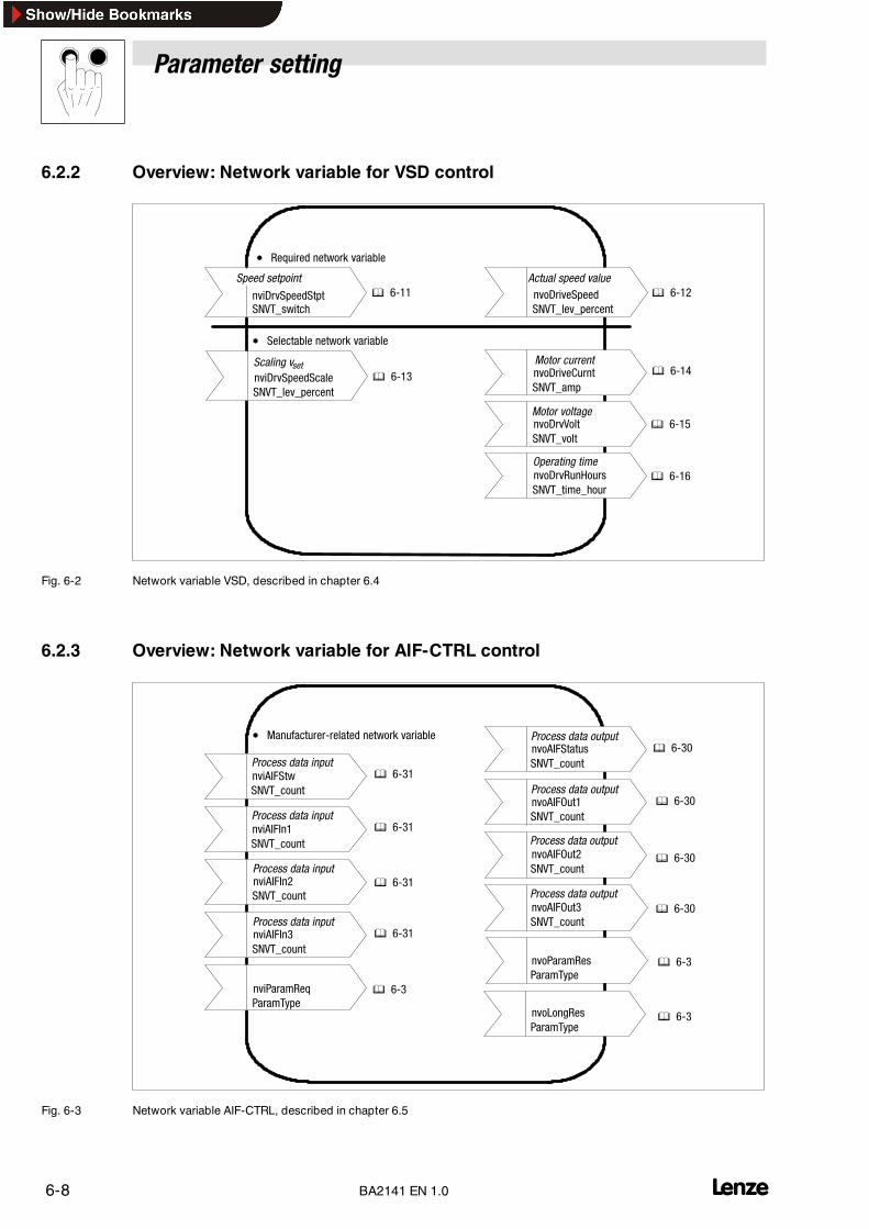
6.2.2 Overview: Network variable for VSD control
nviDrvSpeedStptSNVT_switch
nvoDriveSpeedSNVT_lev_percent
nvoDriveCurntSNVT_amp
nvoDrvVoltSNVT_volt
nvoDrvRunHoursSNVT_time_hour
nviDrvSpeedScaleSNVT_lev_percent
• Required network variable
• Selectable network variable
Actual speed value
Scaling vset
Speed setpoint
Motor current
Motor voltage
Operating time
� 6-11
� 6-13
� 6-12
� 6-14
� 6-15
� 6-16
Fig. 6-2 Network variable VSD, described in chapter 6.4
6.2.3 Overview: Network variable for AIF-CTRL control
nviAIFStwSNVT_count
nviAIFIn1SNVT_count
nviAIFIn2SNVT_count
nviAIFIn3SNVT_count
nviParamReqParamType
nvoParamResParamType
nvoAIFOut3SNVT_count
nvoAIFOut2SNVT_count
nvoAIFOut1SNVT_count
nvoAIFStatusSNVT_count
• Manufacturer-related network variable Process data output
Process data output
Process data output
Process data output
Process data input
Process data input
Process data input
Process data input
nvoLongResParamType
� 6-3
� 6-3
� 6-3
� 6-31
� 6-31
� 6-31
� 6-31
� 6-30
� 6-30
� 6-30
� 6-30
Fig. 6-3 Network variable AIF-CTRL, described in chapter 6.5

Parameter setting
6-9L BA2141 EN 1.0
6.2.4 Overview: Configuration variable for VSD control
nciLocation (O)
nciAIFDefStwnciAIFRecHrtBtnciDrvSpeedScale (O)nciRampDownTm (M)nciRampUpTm (M)nciNmlFreq (M)nciNmlSpeed (M)nciMinSpeed (M)nciMaxSpeed (M)nciMinOutTm (O)nciSndHrtBt (O)nciRcvHrtBt (O)
� 6-17� 6-18� 6-19� 6-20� 6-21� 6-22� 6-23� 6-24� 6-25� 6-26� 6-29� 6-27� 6-28
Fig. 6-4 Configuration variable VSD, described in chapter 6.4.2

Parameter setting
6-10 LBA2141 EN 1.0
6.3 Node Object
6.3.1 Inhibit / Enable all objects
All objects can be inhibited or enabled via the network variable nvi00Request:
• Inhibit: nvi00Request.object_id = Object no.nvi00Request.object_request = 1 (RQ_DISABLED)
• Enable: nvi00Request.object_id = Object no.nvi00Request.object_request = 7 (RQ_ENABLED)
6.3.2 Status messages
In the event of a communication error between the LON interface module and the basic unit the bitcomm_failure will be set under nvo00State.
Structure Type Definition:
typedef struct {
unsigned long object_id;unsigned invalid_id : 1;unsigned invalid_request : 1;unsigned disabled : 1;unsigned out_of_limits : 1;unsigned open_circuits : 1;unsigned out_of_service : 1;unsigned mechanical fault : 1;unsigned feedback_failure : 1;unsigned over_range : 1;unsigned under_range : 1;unsigned electrical_fault : 1;unsigned unable_to_measure : 1;unsigned comm_failure : 1;unsigned fail_self_test : 1;unsigned self_test_in_progress : 1;unsigned locked_out : 1;unsigned manual_control: 1;unsigned in_alarm: 1;unsigned in_override: 1;unsigned report_mask: 1;unsigned programming_mode: 1;unsigned programming_fail: 1;unsigned alarm_notify_disabled: 1;unsigned reserved1: 1;unsigned reserved1: 8;
} SNVT_obj_status;

Parameter setting
6-11L BA2141 EN 1.0
6.4 VSD control VSD
6.4.1 Network variable (VSD)
6.4.1.1 Speed setpoint
network input SNVT_switch nviDrvSpeedStpt;
The input network variable offers the following:
• Motor start/stop option
• Speed selection in percent(resolution = 0.5% ref. to value selected under nciMaxSpeed)
Input range
Status Value Command Explanation0 (FALSE) NA Stop1 (TRUE) 0 0%1 (TRUE) 1 to 200 0.5% to 100.0%1 (TRUE) 201 to 255 100.0%jFFhex NA AUTO (invalid) Standard value.
This value will be set after a reset or if the time set undernciRcvHrtBt expires with an update of the variables.AUTO has the same function as stop, but is also used to check whetherthe “Receive Heartbeat Time” has expired.
Function
The speed setpoint for the controller is calculated as follows:
nsoll =nviDrvSpeedStpt.value× nviDrvSpeedScale
100
The result is used as setpoint preselection in per cent. The setpoint selection is mapped to the AIFinput data word 1 of the process data channel. Since 82XX and 93XX controllers expect differentvalues here, the setpoints are converted in two different ways.
82XX controllers use a setpoint in Hz and a factor of 50 (24000 = 480Hz).
The value for AIF data word 1 is calculated as follows:
AIFIn.W1= nviDrvSpeedStPt.value100[%]× 2 [NVfactor]
× nviDrvSpeedScale100[%]× 200 [NVfactor]
× nciNmlFreq10 [NVfactor]
× 50 [AIFfactor]
93XX servos use a setpoint in % and a factor of 163.83 (16383 = 100%).
The value for AIF input data word 1 results from the following:
AIFIn.W1= nviDrvSpeedStPt.value100[%]× 2 [NVfactor]
× nviDrvSpeedScale100[%]× 200 [NVfactor]
× 16383 [AIFfactor]
If the result of the calculation is a negative value, the direction of rotation will be reversed. This is doneby setting bit 2 in the AIF control word.

Parameter setting
6-12 LBA2141 EN 1.0
6.4.1.2 Actual speed value
network output SNVT_lev_percent nvoDrvSpeed;
The output network variable indicates the current speed as proportion of the rated value. Displayvalue in [%].
Output range
The possible bandwidth for the output variables is between –163.840% and 163.830%. Resolution:0.005%.
The value +163.835% (7FFFhex) is assumed to be wrong.
Update rate
The variable is sent if the value changes or if the time set under Maximum Send Time (nciSndHrtBt)has expired.
The variable value will not be sent quicker than set in Minimum Send Time (nciNinOutTm).
Standard Service Type
The Standard Service Type is acknowledged.
Function
The value of nvoDrvSpeed results from the AIF output data word 1 of the process data channel.Since 82XX and 93XX send different value, the actual speed values are converted in different ways.
82XX controllers send actual values in [Hz] and a factor of 50 (24000 = 480Hz).
The value for nvoDrvSpeed results from:
nvoDrvSpeed= AIFOut.W1nciNmlFreq
10 [NVfactor]× 50[AIFfactor]× 100[%]× 200 [NVfactor]
93XX controllers send actual values in [%] and a factor of 163.83 (16383 = 100%).
The value for nvoDrvSpeed results from:
nvoDrvSpeed= AIFOut.W116383 [NVfactor]
× 100[%]× 200 [NVfactor]

Parameter setting
6-13L BA2141 EN 1.0
6.4.1.3 Scaling of the speed setpoint
network input SNVT_lev_percent nviDrvSpeedScale;
The setpoint can be scaled through this input network variable (nviDrvSpeedStPt).
Negative values result in the opposite direction of rotation.
Actual speed setpoint = nviDrvSpeedStpt× nviDrvSpeedScale
Example:
• nviDrvSpeedStpt.value = 50%
• nviDrvSpeedScale = –150%
The actual speed setpoint is –75% of the rated value.
Input range
The possible bandwidth for the input variables is between –163.840% and 163.830%. Resolution0.005%.
The value +163.835% (7FFFhex) is assumed to be wrong.
Standard value
The standard value is determined by the “Configuration Property” nciDrvSpeedScale.
This value will be set after a reset or if the time set under nciRcvHrtBt passes without an updateof the variable.
Function
The value of nviDrvSpeedStPt.value is multiplied with the value of nviDrvSpeedScale anddivided by 100.
The result is used as setpoint preselection in per cent. The setpoint selection is mapped to the AIFinput data word 1 of the process data channel. Since 82XX and 93XX controllers expect differentvalues here, the setpoints are converted in two different ways.
82XX controller expect the setpoint in [Hz] and a factor of 50 (24000 = 480Hz). The value for AIF dataword 1 is calculated as follows:
AIFIn.W1= nviDrvSpeedStPt.value100[%]× 2 [NVfactor]
× nviDrvSpeedScale100[%]× 200 [NVfactor]
× nciNmlFreq10 [NVfactor]
× 50 [AIFfactor]
93XX controllers expect the setpoint in [%] and a factor of 163.83 (16383 = 100%). The value for AIFinput data word 1 results from the following:
AIFIn.W1= nviDrvSpeedStPt.value100[%]× 2 [NVfactor]
× nviDrvSpeedScale100[%]× 200 [NVfactor]
× 16383 [AIFfactor]
If the result of the calculation is a negative value, the direction of rotation will be reversed. This is doneby setting bit 2 in the AIF control word.

Parameter setting
6-14 LBA2141 EN 1.0
6.4.1.4 Motor current
network output SNVT_amp nvoDriveCurnt;
This network variable outputs the actual output current in Ampere.
Output range
The possible bandwidth for the output variable is between –3276.8 A and +3276.6 A. Resolution 0.1A.
The value +3276.7 A (7FFFhex) is assumed to be wrong.
Update rate
The variable is sent if the value has changed or if the time set under Configuration Property MaximumSend Time (nciSndHrtBt) has expired.
The variable value will not be sent quicker than set in Configuration Property Minimum Send Time(nciMinOutTm).
Standard Service Type
The Standard Service Type is acknowledged.
Function
The output current is cyclically read from the drive
(code 0054, subcode 00). The value is calculated as follows:
nvoDriveCurnt= SDF.LW10000 [AIFfactor]
× 10 [NVfactor]
If an error occurs during the query, nvoDriveCurnt will be set to 7FFFhex.

Parameter setting
6-15L BA2141 EN 1.0
6.4.1.5 Motor voltage
network output SNVT_volt nvoDrvVolt;
The output network variable indicates the current output voltage in [Volt].
Output range
The possible bandwidth for the output variable is between –3276.8 V and +3276.6 V.Resolution 0.1 V.
The value +3276.7 V (7FFFhex) is assumed to be wrong.
The typical output range is between 0 V and 700 V.
Update rate
The variable is sent if the value has changed.
The variable is sent as heart beat if the time set under Configuration Property Maximum Send Time(nciSndHrtBt) has expired.
The variable value will not be sent quicker than set in Configuration Property Minimum Send Time(nciMinOutTm).
Function
The current output voltage is cyclically read by the drive (code 0052, subcode 00). The value iscalculated as follows:
nvoDriveVolt= SDF.LW10000 [AIFfactor]
× 10 [NVfactor]
If an error occurs during the query, nvoDrvVolt is set to 7FFFhex.
Standard Service Type
The Standard Service Type is acknowledged.

Parameter setting
6-16 LBA2141 EN 1.0
6.4.1.6 Operating time
network output SNVT_time_hour nvoDrvRunHours;
This network variable output the entire operating time in hours.
Output range
The possible bandwidth for the output variable is between 0 and 65534 hours. Resolution: 1 hour.
The value of 65535 hours (FFFFhex) is assumed to be wrong.
Update rate
The variable is sent if the value has changed.
The variable value will not be sent quicker than set im Configuration Property Minimum Send Time(nciMinOutTm).
Standard Service Type
The Standard Service Type is acknowledged.
Function
The operating time is cyclically read by the drive (code 0174, subcode 00).
82XX controllers send the operating time in hours with the AIF factor 10000 (30000 = 3 hours).
The value is calculated as follows:
nvoDriveRunHours= SDF.LW10000 [AIFfactor]
× 1 [NVfactor]
93XX controllers send the operating time in seconds without AIF factor.
The value is calculated as follows:
nvoDriveRunHours= SDF.LW3600 [seconds
hour ]× 1 [NVfactor]
If an error occurs during the query, nvoDrvRunHours is set to FFFFhex.

Parameter setting
6-17L BA2141 EN 1.0
6.4.2 Configuration variable (VSD)
6.4.2.1 Location label
network input config SNVT_str_asc nciLocation;
This configuration variable can be used to store a 31-byte string.
Input range
A ZERO terminated string of max. 31 byte
Standard value
ZERO
SCPT Reference
SCPT_location (17)

Parameter setting
6-18 LBA2141 EN 1.0
6.4.2.2 Receive Heartbeat Time
network input config SNVT_time_sec nciRcvHrtBt;
This configuration variable is used to store the time expected for an update, if this time expireswithout an update, the values for the following network variables will be reset to their default settings:
nviDrvSpeedStpt (� 6-11)
nviDrvSpeedScale (� 6-13)
It is also used to monitor the variables configured in nciAIFRecHrtBt (� 6-27). The variables are:nviAIFStw, nviAIFIn1, nviAIFIn2, nviAIFIn3.
Input range
The possible bandwidth for the configuration variable is between 0.0 and 6553.4 seconds (resolution0.1 seconds)
Standard value
0.0 (no monitoring)
SCPT Reference
SCPTmaxRcvTime (48)

Parameter setting
6-19L BA2141 EN 1.0
6.4.2.3 Maximum Send Time
network input config SNVT_time_sec nciSndHrtBt;
This configuration variable stores the time needed before the following network variables will beupdated:
nvoDrvSpeed
nvoDrvCurnt
nvoDrvVolt
nvoAIFStw
nvoAIFOut1
nvoAIFOut2
nvoAIFOut3
Input range
The possible bandwidth for the configuration variable is between 0.0 and 6553.4 seconds (resolution0.1 seconds)
Standard value
0.0 (no automatic update)
SCPT Reference
SCPTmaxSendTime(49)

Parameter setting
6-20 LBA2141 EN 1.0
6.4.2.4 Minimum Send Time
network input config SNVT_time_sec nciMinOutTm;
Here you store the time needed before an output network variable can be updated.
Input range
The possible bandwidth for the configuration variable is between 0.1 and 6553.4 seconds (resolution0.1 seconds)
Standard value
0.5 seconds
SCPT Reference
SCPTminSendTime (52)

Parameter setting
6-21L BA2141 EN 1.0
6.4.2.5 Maximum speed
network input config SNVT_lev_percent nciMaxSpeed;
The configuration variable contains the maximum motor speed. The value is indicated as percentageof the rated value (NciNmlSpeed).
Input range
The possible bandwidth for the configuration variable is between –163.840% and 163.830%(resolution 0.005%). The value +163.835% (7FFFhex) is assumed to be wrong.
The entered value will be checked by means of the following formula:
–163.840% ≤ Minimum speed � Maximum speed ≤ 163.830%
If the result is wrong, the lower value is taken as maximum speed.
Standard value
100.000 %
Function
After a change of the maximum speed, the value will be sent to the drive via the parameter channel(code 0011, subcode 00).
SCPT Reference
SCPTmaxSetpoint (50)

Parameter setting
6-22 LBA2141 EN 1.0
6.4.2.6 Minimum speed
network input config SNVT_lev_percent nciMinSpeed;
The configuration variable contains the minimum motor speed. The value is indicated as percentageof the rated value (nciNmlSpeed).
Input range
The possible bandwidth for the configuration variable is between –163.840% and 163.830%(resolution 0.005%). The value +163.835% (7FFFhex) is assumed to be wrong.
The entered value will be checked by means of the following formula:
–163.840% ≤ Minimum speed � Maximum speed ≤ 163.830%
If the result is wrong, the lower value is taken as minimum speed.
Standard value
0.000 %
Function
After a change of the minimum speed, the value will be sent to the drive via the parameter channel(code 0010, subcode 00).
SCPT Reference
SCPTminSetpoint (53)

Parameter setting
6-23L BA2141 EN 1.0
6.4.2.7 Rated speed value
network input config SNVT_rpm nciNmlSpeed;
This configuration variable contains the rated motor speed in rpm.
Input range
The possible bandwidth for the configuration variable is between 0 and 65534 rpm (resolution 1 rpm)
Standard value
3000 rpm
Function
After a change of the rated speed, the value will be sent to the drive via the parameter channel (code0087, subcode 00).
SCPT Reference
SCPTnomRPM (158)

Parameter setting
6-24 LBA2141 EN 1.0
6.4.2.8 Rated frequency
network input config SNVT_freq_hz nciNmlFreq;
This configuration variable contains the rated motor frequency in Hz.
Input rangeThe possible bandwidth for the configuration variable is between 0 and 6553,4 Hz (resolution 0,1 Hz)
Standard value
50 Hz
Function
After a change of the rated frequency, the value will be sent to the drive via the parameter channel(code 0089, subcode 00).
SCPT Reference
SCPTnomFreq (159)
Parameter setting
6-25L BA2141 EN 1.0
6.4.2.9 Acceleration time
network input config SNVT_time_sec nciRampUpTm;
This configuration variable indicates the acceleration time of the motor.
Input range
The possible bandwidth for the configuration variable is between 0 and 6553.4 seconds (resolution0,1 Sekunden)
Standard value
5 seconds
Function
After a change of the acceleration time, the value will be sent to the drive via the parameter channel(code 0012, subcode 00).
SCPT Reference
SCPTrampUpTm (160)

Parameter setting
6-26 LBA2141 EN 1.0
6.4.2.10 Deceleration time
network input config SNVT_time_sec nciRampDownTm;
This configuration variable indicates the deceleration time of the motor.
Input range
The possible bandwidth for the configuration variable is between 0 and 6553.4 seconds (resolution0,1 Sekunden)
Standard value
5 seconds
Function
After a change of the deceleration time, the value will be sent to the drive via the parameter channel(code 0013, subcode 00).
SCPT Reference
SCPTrampDownTm (161)

Parameter setting
6-27L BA2141 EN 1.0
6.4.2.11 Receive heartbeat for AIF-CTRL
network input config SNVT_state nciAIFRecHrtBt;
Here you can select the manufacturer-specific network variables (nviAIFStw, nviAIFIn1,nviAIFIn2, nviAIFIn3) which are to be monitored with a Receive Timeout.
nciAIFRecHrtBt.bit0 = 0 – No timeout monitoring for nviAIFStw
nciAIFRecHrtBt.bit0 = 1 – Timeout monitoring for nviAIFStw
nciAIFRecHrtBt.bit1 = 0 – No timeout monitoring for nviAIFIn1
nciAIFRecHrtBt.bit1 = 1 – Timeout monitoring for nviAIFIn1
nciAIFRecHrtBt.bit2 = 0 – No timeout monitoring for nviAIFIn2
nciAIFRecHrtBt.bit2 = 1 – Timeout monitoring for nviAIFIn2
nciAIFRecHrtBt.bit3 = 0 – No timeout monitoring for nviAIFIn3
nciAIFRecHrtBt.bit3 = 1 – Timeout monitoring for nviAIFIn3
If one of the monitored variables gets a Receive Heartbeat Timeout, the function selected innciAIFDefStw will be carried out.
Input range
The possible range for the input variable is 0 or 1 for every bit.
Only bits 0 and 3 will be evaluated.
Standard value
0

Parameter setting
6-28 LBA2141 EN 1.0
6.4.2.12 Monitoring reaction for AIF-CTRL
network input config SNVT_state nciAIFDefStw;
If one of the monitored variables of the AIF-CTRL gets a Receive Heartbeat Timeout (� 6-30), thefunction selected in nciAIFDefStw will be carried out.
The quick stop functions sets bit 3 in the AIF control word, the controller inhibit function sets bit 9 inthe AIF control word.
Tip!The functions quick stop and controller inhibit will only be reset after all monitored variables havebeen updated within the Receive Heartbeat Timeout.
Input range
The possible bandwidth for the configuration variables is 0, 1 oooder 2
nciAIFDefStw = 0 – No reaction
nciAIFDefStw = 1 – Quick stop
nciAIFDefStw = 2 – Controller inhibit
Standard value
0

Parameter setting
6-29L BA2141 EN 1.0
6.4.2.13 Default value for nviDrvSpeedScale
network input config_lev_percent nciDrvSpeedScale;
This value determines the default setting for nciDrvSpeedScale. The current configurationvariable nciDrvSpeedScale is overwritten with the default value
• after a reset or
• if the time from nciRcvHrtBt passes without an update of the variable nciDrvSpeedScale.
Input range
The possible bandwidth for the input variable is between -163.840 % and 163.830 % (resolution0.005 %).
The value +163.835 % (7FFFhex) is assumed to be wrong.
Standard value
0
SCPT Reference
SCPTdefScale (162)
Parameter setting
6-30 LBA2141 EN 1.0
6.5 Device control AIF-CTRL
6.5.1 General information
6.5.1.1 Output variable
network output SNVT_count nvoAIFStatus;
network output SNVT_count nvoAIFOut1;
network output SNVT_count nvoAIFOut2;
network output SNVT_count nvoAIFOut3;
The output network variable nvoAIFStatus is directly taken from the AIF status word.
The output network variables nvoAIFOut1 to nvoAIFOut3 are directly taken from thecorresponding AIF data words.
Output range
The possible bandwidth for the output variable is between 0 and 65535.
Update range
The variables are sent if the value changes or if the time set under Configuration Property MaximumSend Time (nciSndHrtBt) has expired.
The variable value will not be sent quicker than set in Configuration Property Minimum Send Time(nciMinOutTm).
Standard Service Type
The Standard Service Type is acknowledged.

Parameter setting
6-31L BA2141 EN 1.0
6.5.1.2 Input variable
network input SNVT_count nviAIFStw;
network input SNVT_count nviAIFIn1;
network input SNVT_count nviAIFIn2;
network input SNVT_count nviAIFIn3;
The input network variable nviAIFStw is directly accepted by the AIF control word.
The input network variables nviAIFIn1 to nviAIFIn3 are directly accepted by the correspondingAIF input data words.
1Input range
The possible bandwidth for the output variable is between 0 and 65535.
Standard value
The standard value after a reset is 0 for all four variables.
The standard value for nviAIFStw is determined by the configuration properties nciAIFDefStwand nciAIFRecHrtBt. nciAIFDefStw indicates the function to be executed in the event of aReceive Heartbeat Timeout and nciAIFRecHrtBt indicates the variables monitored by a ReceiveHeartbeat.
nciAIFRecHrtBt.bit0 = 1 – Timeout monitoring for nviAIFStw
nciAIFRecHrtBt.bit1 = 1 – Timeout monitoring for nviAIFIn1
nciAIFRecHrtBt.bit2 = 1 – Timeout monitoring for nviAIFIn2
nciAIFRecHrtBt.bit3 = 1 – Timeout monitoring for nviAIFIn3
nciAIFStw = 0 – No reaction
nciAIFStw = 1 – Quick stop
nciAIFStw = 2 – Controller inhibit
If one of the monitored variables gets a Receive Heartbeat Timeout, the function selected innciAIFDefStw will be carried out.
The quick stop functions sets bit 3 in the AIF control word, the controller inhibit function sets bit 9 inthe AIF control word. The functions quick stop and controller inhibit will only be reset after allmonitored variables have been updated within the Receive Timeouts.

Parameter setting
6-32 LBA2141 EN 1.0
6.5.2 Network variable for 82XX controllers
Setpoint source selection
The setpoint source for these controllers is selected under code C0001. An evaluation of processdata is only possible if code C0001 is set to ”3” when the controller is operated together with thefieldbus module.
Therefore the process data channel serves as setpoint source, describing the frequency setpoint(C0046) and the control word (parameter channel, C0135) (see Operating Instructions 82XX).
Tip!Please observe that code C0001 is available in all parameter sets.
Network variable from drive
• nvoAIFStatus reads the status word (� 6-38)
Status wordLOW byte HIGH byte
Bits 0 to 7 of the status word (code C0150) areentered here.
Bits 8 to 15 of the status word (code C0150) areentered here.
• nvoAifOut1 reads the actual frequency value
Actual frequency valueLOW byte HIGH byte
The actual frequency value is read from code C0050. The actual frequency value with the signednormalisation 24000 = 480 Hz is provided here.
Network variable to drive
• nviAIFStw writes the control word (� 6-39)
Control wordLOW byte HIGH byte
Bits 0 to 7 of the control word (code C0135) areentered here.
Bits 8 to 15 of the control word (code C0135) areentered here.
• nviAIFIn1 writes the frequency setpoint
Frequency setpointLOW byte HIGH byte
The frequency setpoint (code C0046 via parameter data channel) is selected as process data word.The normalization differs from the setting under C0046. It is a signed value, 24000 = 480 Hz.

Parameter setting
6-33L BA2141 EN 1.0
6.5.2.1 Status word for 82XX
Bit 820X 821x,822x00 Actual parameter set
0 = Parameter set 1 or 3 active1 = Parameter set 2 or 4 active
Actual parameter set0 = Parameter set 1 or 3 active1 = Parameter set 2 or 4 active
01 IMP (pulse inhibit)0 = Pulses for power stage enabled1 = Pulses for power stage inhibited
IMP (pulse inhibit)0 = Pulses for power stage enabled1 = Pulses for power stage inhibited
02 Imax (current limit reached)0 = Current limit not reached1 = current limit reached
Imax (current limit reached)0 = Current limit not reached1 = current limit reached
03 not assigned fd = fdset0 = fd ≠ fdset1 = fd= fdset
04 fd = fdset0: fd ≠ fdset1: fd = fdset
RFG on = RFG off0 = RFG on ≠ RFG off1 = RFG on = RFG out
05 Qmin (fd ≤ fdQmin)0 = Qmin not active1 = Qmin active
Qmin (fd ≤ fdQmin)0 = Qmin not active1 = Qmin active
06 fd = 0 (act. frequency = 0)0: fd ≠ 01: fd > 0
fd > 0 (actual frequency value = 0)0 = fd ≠ 01 = fd > 0
07 Ctrl. inhibit (controller inhibit)0 = controller not inhibited1 = controller inhibited
Ctrl. inhibit (controller inhibit)0 = controller not inhibited1 = controller inhibited
08...11 Controller status0 = Controller initialization8 = Error active
Controller status0 = Controller initialization1 = Switch on inhibit3 = Operation inhibited4 = Flying-restart circuit active5 = DC brake active6 = Operation enabled7 = Message active8 = Error active
12 Overtemperature warning0 = No warning1 = Warning
Overtemperature warning0 = No warning1 = Warning
13 UGmax (DC-bus overvoltage)0 = No overvoltage1 = overvoltage
UGmax (DC-bus overvoltage)0 = No overvoltage1 = overvoltage
14 Direction of rotation0 = CW rotation1 = CCW rotation
Direction of rotation0 = CW rotation1 = CCW rotation
15 Ready0 = not ready for operation1 = ready for operation
Ready0 = not ready for operation1 = ready for operation

Parameter setting
6-34 LBA2141 EN 1.0
2141LON012
16 Bit
16 Bit
.B15
.B12
.B0
.B1
.B2
.B3
.B4
.B8
.B9
.B10
.B11
.B13
.B14
.B5
.B6
.B7
IMP
fd=fdsoll / HLG
Qmin
Imax
- / fd=fdsoll
PAR
fd>0
RSP
Ugmax
R/L
RDY
Tü AIF
C0050
STATB11 B10 B9 B8
0
01......
0
11......
0
00......
0
00......
0
23......
Fig. 6-5 Read access to status word and actual frequency in 82XX (fixed assignment)

Parameter setting
6-35L BA2141 EN 1.0
6.5.2.2 Control word for 82XX
Bit 820X 821x,822xBit 820X 821x,822x
00,00 = C0046 active01 = JOG1 active in C0037
00 = C0046 active01 = JOG1 active in C003700,
01 10 = JOG2 active in C003811 = JOG3 active in C0039
01 JOG1 active in C003710 = JOG2 active in C003811 = JOG3 active in C0039
02 CW/CCW (CW rotation/CCW rotation)0 = CW rotation1 = CCW rotation
CW/CCW (CW rotation/CCW rotation)0 = CW rotation1 = CCW rotation
03 QSP (quick stop)0 = QSP not active1 = QSP active
QSP (quick stop)0 = QSP not active1 = QSP active
04 Reserved RFG stop (stop of the ramp function generator)0 = RFG stop not active1 = RFG stop active
05 Reserved RFG zero (deceleration along the Tif ramp C0013)0 = RFG zero not active1 = RFG zero active
06 Reserved UP function for motor potentiometer0 = UP not active1 = UP active
07 Reserved DOWN function for motor potentiometer0 = DOWN not active1 = DOWN active
08 Reserved Reserved09 Ctrl. inhibit (controller inhibit)
0 = controller not inhibited1 = controller inhibited
Ctrl. inhibit (controller inhibit)0 = controller not inhibited1 = controller inhibited
10 Reserved Reserved11 Reserved TRIP reset
0 -> 1 = Edge from 0 to 112 PAR1 (Parameter set changeover)
0 -> 1 = Parameter set1 -> 0 = Parameter set
PAR1 (Parameter set changeover)0 -> 1 = Parameter set1 -> 0 = Parameter set
13 Reserved Reserved14 DC brake (DC injection brake)
0 = DC brake not active1 = DC brake active
DC brake (DC injection brake)0 = DC brake not active1 = DC brake active
15 Reserved Reserved
2141LON010
AIF
C0046
.B15
.B13
.B14
.B12
.B0
.B1
.B2
.B3
.B4.........
.B8
.B9
.B10
.B11
QSP
CINH
TRIP-SET
TRIP-RESET
16 Bit
16 Bit
0 JOG/
C046
0 1 1
0 1 0 1
PAR
GSB
R/L
Fig. 6-6 Access to control word and actual frequency in 82XX (fixed assignment)

Parameter setting
6-36 LBA2141 EN 1.0
6.5.3 Network variable for 8200 vector controllers
Setpoint source selection
The setpoint source for these controllers is selected under code C0001. An evaluation of processdata is only possible if code C0001 is set to ”3” when the controller is operated together with thefieldbus module. (Selection: process data channel of a fieldbus module AIF-IN.W1 or AIF-IN.W2).
The process data channel which describes the frequency setpoint (C0046) and the control word(parameter channel, C0135) is the setpoint source (see 8200 vector Operating Instructions).
Check under C0412/x whether the setpoint source is assigned to the signal wanted.
Tip!Please ensure that code C0001 or C0410 is the same for all parameter sets.
Digital and analog input and output signals can be freely configured (see Operating Instructions for8200 vector; codes C0410, C0412, C0417 and C0421)The change of the code C0001 to 3 starts thepreconfiguration of the process data words in the controller.

Parameter setting
6-37L BA2141 EN 1.0
Network variable from drive (see function block AIF-OUT (� 6-38) )
• nvoAIFStatus reads bits B0 ... B15 of the status word AIF-STAT (� 6-38)
Status word AIF-STATLOW byte HIGH byte
Bits 0 to 7 of the status word will be entered here. Bits 8 to 15 of the status words will be entered here.
• nvoAifOut1 reads the output word AIF-OUT.W1
Actual valueLOW byte HIGH byte
The actual frequency value with the signed normalisation 24000 = 480 Hz is provided here.Torque values are normalised with 16384 = 100%. AIF-OUT.W1 see C0421/1, (Operating Instructions for 8200 vector)
• nvoAifOut2 reads the output word AIF-OUT.W2
Actual valueLOW byte HIGH byte
The actual frequency value with the signed normalisation 24000 = 480 Hz is provided here.Torque values are normalised with 16384 = 100%. AIF-OUT.W2 see C0421/2, (Operating Instructions for 8200 vector)
Network variable to drive (see function block AIF-IN (� 6-40))
• nviAIFStw writes bits B0 ... B15 in the control word AIF-CTRL (� 6-39)
Control word AIF-CTRLLOW byte HIGH byte
Bits 0 to 7 of the control word will be entered here. Bits 8 to 15 of the control word will be entered here.
• nviAIFIn1 writes the input word AIF-IN.W1
AIF-IN.W1LOW byte HIGH byte
The frequency setpoint is preselected as process data word. The normalisation differs from the setting under C0046. It is a signed value, 24000= 480 Hz. AIF-IN.W1 see C0412/x, Wert “10” (Operating Instructions for 8200 vector)
• nviAIFIn2 writes the input word AIF-IN.W2
AIF-IN.W2LOW byte HIGH byte
The frequency setpoint is preselected as process data word.The normalisation differs from the setting under C0046. It is a signed value, 24000 = 480 Hz.AIF-IN.W2 see C0412/x, Wert “11” (Operating Instructions for 8200 vector)

Parameter setting
6-38 LBA2141 EN 1.0
6.5.3.1 Status word for 8200 vector
Bit 8200vector default setting00 DCTRL-PAR-B001 DCTRL1-IMP02 MCTRL1-IMAX03 MCTRL1-RFG1=NOUT04 NSET1-RFG1-I=005 PCTRL1-QMIN06 DCTRL1-NOUT=007 DCTRL1-CINH08...11 Controller status
0 = Controller initialization1 = Switch-on inhibit3 = Operation inhibited4 = Flying-restart circuit active5 = DC brake active6 = Operation enabled7 = Message active8 = Error active
12 DCTRL1-OH-WARN13 DCTRL1-OV14 DCTRL1-CCW15 DCTRL1-RDY
2141LON013
AIF-OUT
AIF-STAT
16 Bit
16 Bit
.B15
.B12
.B0
.B1
.B2
.B3
.B4
.B8
.B9
.B10
.B11
16 Bit
.B13
.B14
.B5
.B6
.B7
.B0C0417/1
AIF-OUT.W1
AIF-OUT.W2
.B1DCTRL1-IMP
.B2C0417/3
.B3C0417/4
.B4C0417/5
.B5C0417/6
.B6DCTRL1-NOUT=0
.B7DCTRL1-CINH
.B8DCTRL1-STAT*1
.B9DCTRL1-STAT*2
.B10
.B11DCTRL1-STAT*4
DCTRL1-STAT*8.B12
DCTRL1-OH-WARN.B13
DCTRL1-OV.B14
C0417/15.B15
C0417/16
AIF
STAT1
C0421/1
C0421/2
Fig. 6-7 Function block AIF-OUT in 8200 vector
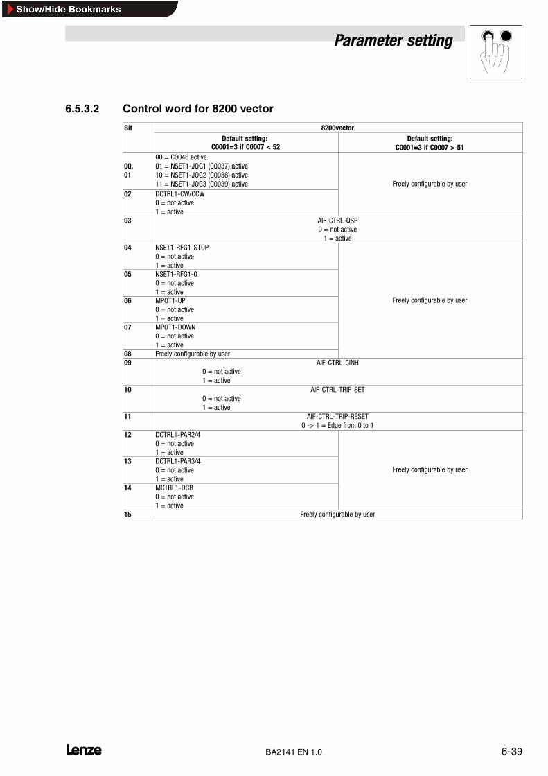
Parameter setting
6-39L BA2141 EN 1.0
6.5.3.2 Control word for 8200 vector
Bit 8200vectorBitDefault setting:
C0001=3 if C0007 < 52Default setting:
C0001=3 if C0007 > 51
00,00 = C0046 active01 = NSET1-JOG1 (C0037) active00,
0101 NSET1 JOG1 (C0037) active10 = NSET1-JOG2 (C0038) active11 = NSET1-JOG3 (C0039) active Freely configurable by user
02 DCTRL1-CW/CCW0 = not active1 = active
y g y
03 AIF-CTRL-QSP0 = not active1 = active
04 NSET1-RFG1-STOP0 = not active1 = active
05 NSET1-RFG1-00 = not active1 = active
06 MPOT1-UP0 = not active1 = active
Freely configurable by user
07 MPOT1-DOWN0 = not active1 = active
08 Freely configurable by user09 AIF-CTRL-CINH
0 = not active1 = active
10 AIF-CTRL-TRIP-SET0 = not active1 = active
11 AIF-CTRL-TRIP-RESET0 -> 1 = Edge from 0 to 1
12 DCTRL1-PAR2/40 = not active1 = active
13 DCTRL1-PAR3/40 = not active1 = active
Freely configurable by user
14 MCTRL1-DCB0 = not active1 = active
15 Freely configurable by user

Parameter setting
6-40 LBA2141 EN 1.0
2141LON011
AIF
AIF-IN
AIF-CTRL
AIF-IN.W2
AIF-IN.W1
.B15
.B12
.B0
.B1
.B2
.B3
.B4...
......
......
......
......
......
...
.B8
.B9
.B10
.B11
DCTRL
QSP
CINH
TRIP-SET
TRIP-RESET
DCTRL16 Bit
16 Bit
16 Bit
Fig. 6-8 Function block AIF-IN in 8200 vector

Parameter setting
6-41L BA2141 EN 1.0
6.5.4 Network variable for 93XX controllers
Setpoint source selection
With 93XX controllers it is not possible to select a setpoint source by means of one code only. It ishowever easy to adapt the controller to the drive task because it is working with preconfiguredfunction blocks which only have to be connected. For this it is not necessary to have specialprogramming skills.
The user himself can link the function blocks. It is however easier to use Lenze preconfigurationswhich are already stored in the controller ROM. The Lenze preconfigurations (see code C0005)determine the source (terminal, keypad, fieldbus module) which describes the frequency setpointand the control word.
The value in code C0005 must be set to ”xxx3” for LON bus operation (x = selected preconfiguration).
Fore more information please see the corresponding Manual and Operating Instructions for thecontroller.
With the 93XX controller the process data assignment can be changed by reconfiguring the functionblocks AIF-IN and AIF-OUT.
Network variable from drive
• nvoAIFStatus = STAT.B0 ... STAT.B15 (status word)
Status wordLOW byte HIGH byte
Bits 0 to 7 of the status word will be entered here. Bits 8 to 15 of the status word will be entered here (see chapter6.5.4.1). The description of the bits can be obtained from the CodeTable.
• nvoAifOut1 = AIF-OUT.W1
• nvoAifOut2 = AIF-OUT.W2
• nvoAifOut3 = AIF-OUT.W3
AIF-OUT.WxLOW byte HIGH byte
The actual frequency value with the signed normalisation 24000 = 480 Hz is provided here.
AIF-OUT.W1 to AIF-OUT.W3 depend on the signal configuration selected under L-C0005. Fordetailed description of the 93XX signal configuration see the Operating Instructions for 93XX (onlythe main configurations: 1000, 4000, 5000, etc.) or the Manual 93XX.
In the controller, other signals can be assigned to AIF-OUT.W1 to AIF-OUT.W3. For this, thefunction-block configuration - described in the Manual 93XX - is used.
The function block AIF-OUT determines the controller output data as data interface for the 2141fieldbus module.

Parameter setting
6-42 LBA2141 EN 1.0
Signal configuration (L-C0005) AIF-OUT.W1 AIF-OUT.W2 AIF-OUT.W3 AIF-OUT.D1
Speed control 1003/1013/1113MCTRL-NACTActual speed100 % = 16383
MCTRL-MSET2Torque display100 % = 16383
MCTRL-NSET2Speed controller input
100 % = 16383
Torque control 4003/4013/4113MCTRL-MSET2Torque display100 % = 16383
MCTRL-NACTAct. speed in %100 % = 16383
MCTRL-NSET2Speed controller input
100 % = 16383
DF master 5003/5013/5113MCTRL-NACTActual speed100 % = 16383
MCTRL-MSET2Torque display100 % = 16383
MCTRL-NSET2Speed controller input
100 % = 16383
DF-slave bus 6003/6013/6113MCTRL-NACTActual speed100 % = 16383
MCTRL-PHI-ACTActual phase
MCTRL-MSET2Torque setpoint in %
100 % = 16383
DF-slave cascade 7003/7013/7113MCTRL-NACTActual speed100 % = 16383
MCTRL-PHI-ACTActual phase
MCTRL-MSET2Torque setpoint in %
100 % = 16383 not assigned
Cam profiler 1xxx3MCTRL-NACTActual speed100 % = 16383
not assigned not assigned
Positioning 2xxx3MCTRL-NACTActual speed100 % = 16383
not assigned not assigned
vector control1xx3/4xx3/5xx3/10xx3
MCTRL-NACTActual speed100 % = 16383
MCTRL-IACT MCTRL-NSET2Speed controller input
100 % = 16383
vector control6xx3/7xx3/8xx3/9xx3
MCTRL-NACTActual speed100 % = 16383
MCTRL-PHI-ANA MCTRL-MSET2Torque setpoint in %
100 % = 16383
vector control 110x3 not assigned not assigned not assigned
For more detailed information about the function block AIF-OUT see the Manual 93XX.

Parameter setting
6-43L BA2141 EN 1.0
6.5.4.1 Status word for 93XX
9300 Servo Servopositioningcontroller
Servo camprofiler
vector
C0005 1xx3 4xx3 5xx3 6xx3,7xx3 2xxx3 1xxx3 xxx, 2xxx,3xxx, 5xxx,10xxx, 11xxx
4xxx 6xxx, 7xxx,8xxx, 9xxx
0 DCTRL-PAR1-0 DCTRL-PAR1-0 DCTRL-PAR1-0 DCTRL-PAR1-0 not assigned CERR1-ERR DCTRL-PAR1-0 DCTRL-PAR1-0 DCTRL-PAR1-01 DCTRL-IMP DCTRL-IMP DCTRL-IMP DCTRL-IMP DCTRL-IMP DCTRL-IMP DCTRL-IMP DCTRL-IMP DCTRL-IMP2 MCTRL-IMAX MCTRL-IMAX REF-OK REF-OK POS-REF-OK MCTRL-IMAX MCTRL-IMAX MCTRL-IMAX MCTRL-IMAX3 MCTRL-MMAX not assigned MCTRL-MMAX not assigned not assigned MCTRL-MMAX MCTRL-MMAX MCTRL-IMAX
negatedMCTRL-MMAX
4 NSET-RFG-I=0 MCTRL-IMAXnegated
NSET-RFG-I=0 MCTRL-IMAXnegated
MCTRL-MMAXnegated
DCTRL-TRIP NSET-RFG-I=0 NSET-RFG-I=0 NSET-QSP-OUT
5 QMIN QMIN REF-BUSY REF-BUSY POS-IN-TARGET
CDATA-X0 QMIN QMIN QMIN
6 DCTRL-NACT=0
DCTRL-NACT=0
DCTRL-NACT=0
DCTRL-NACT=0
DCTRL-NACT=0
DCTRL-NACT=0
DCTRL-NACT=0
DCTRL-NACT=0
DCTRL-NACT=0
7 DCTRL-CINH DCTRL-CINH DCTRL-CINH DCTRL-CINH DCTRL-CINH DCTRL-CINH DCTRL-CINH DCTRL-CINH DCTRL-CINH8 ... 11 Controller status:8 ... 11
0 =1 =3 =4 =5 =6 =7 =8 =10 =
Unit initialisationSwitch-on inhibitOperation inhibitedFlying-restart circuit activeDC injection braking activeOperation enabledMessage activeFault activeFail-QSP (only 9300 servo positioning controller)
12 DCTRL-WARN DCTRL-WARN DCTRL-WARN DCTRL-WARN DCTRL-WARN DCTRL-WARN DCTRL-WARN DCTRL-WARN DCTRL-WARN13 DCTRL-MESS DCTRL-MESS DCTRL-MESS DCTRL-MESS DCTRL-MESS DCTRL-MESS DCTRL-MESS DCTRL-MESS DCTRL-MESS14 DCTRL-CW/CC
WDCTRL-CW/CCW
DCTRL-CW/CCW
not assigned DCTRL-AIFL-QSP
DCTRL-CW/CCW
DCTRL-CW/CCW
DCTRL-CW/CCW
DCTRL-CW/CCW
15 DCTRL-RDY DCTRL-RDY DCTRL-RDY DCTRL-RDY DCTRL-RDY DCTRL-RDY DCTRL-RDY DCTRL-RDY DCTRL-RDY

Parameter setting
6-44 LBA2141 EN 1.0
2111IBU002
� � � � � � � �
���������
� � � �
� � � � � �
� � � �
� � � � � �
��������
��������
��������
�
�
� � � �
�
�
� � � �
� � � � � � ! " �
� � � � � �# � � � $ �
� � � � � �% � & ' � $ �
� � � �
� � � � � �# � � � $ �
� � � � � �% � & ' � $ �
� � � (
� " � �
� � � � � � ! $ �� � � ) �
� � � � ) �
� " � � � �
!!!
� � � � � � ! $ �� � � ) �
� � � � � � ! $ �� � � ) �
� � � � ) �
� � � � ) �
� � ! �
" � * # � � + ,
!!!
� � ! � � �
� � ! � � �
� � � � � �
� �� � � � ) �
� � � � ) � �� " � � � �
� " � � � �
!!!� � � � ) � �
� � � � ) � �
� � � �
� � � � � �
� � � � ) �
� � �
� � � � ) �
� � � � ) �
� �
� � � � � � � � � �
���������
� � � �
� � � � � �
� � � �
� � � � � �
��������
��������
- �
��������
�
�
� � � �
�
�
� � � �
� � � � � � ! " �
� � � � � �# � � � $ �
� � � � � �% � & ' � $ �
� � � �
� � � � � �# � � � $ �
� � � � � �% � & ' � $ �
� � � (
� " � �
� � � � � � ! $ �� � � ) �
� � � � ) �
� " � � � �
!!!
� � � � � � ! $ �� � � ) �
� � � � � � ! $ �� � � ) �
� � � � ) �
� � � � ) �
� � ! �
" � * # � � + ,
!!!
� � ! � � �
� � ! � � �
� � � � � �
� �� � � � ) �
� � � � ) � �� " � � � �
� " � � � �!!!� � � � ) � �
� � � � ) � �
� � � �
� � � � � �
� � � � ) �
� � �
� � � � ) �
� � � � ) �
�
� � � �
�
� � � � � � ! " �� � � ( �
� � � ( �
� � � � � �# � � � $ �
� � � � � �% � & ' � $ �
Fig. 6-9 Function block AIF-OUT and AIF-OUT*)
AIF-OUT*) is available for the 9300 technology variants: servo, positioning controller and cam profiler as of softwareversion 2.0 . AIF-OUT.D2 is new.

Parameter setting
6-45L BA2141 EN 1.0
Network variable to drive
The function block AIF-IN determines the input data of the controller as data interface for the 2141fieldbus module. For more detailed information about the function block AIF-IN, see the Manual93XX.
AIF-IN.W1 to AIF-IN.W3 depend on the signal configuration selected under C0005.
Speed setpoint: 100 %= 16383
• nviAIFStw = AIF-CTRL.B0 ... AIF-CTRL.B15 (control word)
Control wordLOW byte HIGH byte
Bits 0 to 7 of the control word will be entered here. Bits 8 to 15 of the control word will be entered here (see chapter6.5.4.2)The description of the bits can be obtained from the Code Table.
• nviAIFIn1 = AIF-IN.W1
• nviAIFIn2 = AIF-IN.W2
• nviAIFIn3 = AIF-IN.W3
AIF-IN.WxLOW byte HIGH byte
Signal configuration (L-C0005) AIF-IN.W1 AIF-IN.W2 AIF-IN.W3 AIF-IN.D1Speed control 1003 / 1013 /
1113NSET-NSpeed setpoint100 % = 16383
Torque control 4003 / 4013 /4113
MCTRL-MADDTorque setpoint100 % = 16383
not assigned
DF master 5003 / 5013 /5113
NSET-NSpeed setpoint100 % = 16383
DF-slave bus 6003 / 6013 /6113
DFSET-A-TRIMPhase trimming
DFSET-N-TRIMSpeed trimming
not assigned not assignedDF-slave cascade 7003 / 7013 /7113
DFSET-VP-DIVDF factor
DFSET-A-TRIMPhase trimming
not assigned not assigned
Cam profiler 1xxx3 NSET1-FACTPositioning 2xxx3 not assignedvector control 1xx3 / 2xx3 / 3xx3
/ 5xx3 / 100x3NLIM-IN1 not assigned
vector control 4xx3 NCTRL-MADDvector control 6xx3 DFSET-A-TRIM DFSET-N-TRIMvector control 7xx3 / 8xx3 / 9xx3 DFSET-VP-DIV DFSET-A-TRIMvector control 100x3 NLIM-IN1 not assignedvector control 110x3 not assigned
not assigned

Parameter setting
6-46 LBA2141 EN 1.0
6.5.4.2 Control word for 93XX
9300 9300 Servo 9300Positioningcontroller
9300Cam profiler
9300 Vector
C0005 1xx3 4xx3 5xx3 6xx3,7xx3 2xxx3 xxx3 1xxx, 2xxx,3xxx, 5xxx,10xxx, 11xxx
4xx3 6xx3,7xx3
0 NSET-JOG*1 not assigned NSET-JOG*1 not assigned not assigned CSEL1-CAM*1 NSET-JOG*1 not assigned not assigned1 NSET-JOG*2 not assigned NSET-JOG*2 not assigned not assigned CSEL1-CAM*2 NSET-JOG*2 not assigned not assigned2 NSET-N-INV NSET-N-INV NSET-N-INV NSET-N-INV not assigned CSEL1-CAM*4 NSET-N-INV not assigned not assigned3 AIF-CTRL.QSP AIF-CTRL.QSP AIF-CTRL.QSP AIF-CTRL.QSP AIF-CTRL.QSP AIF-CTRL.QSP AIF-CTRL.QSP AIF-CTRL.QSP AIF-CTRL.QSP4 NSET-RFG-
STOPNSET-RFG-STOP
NSET-RFG-STOP
NSET-RFG-STOP
POS-PRG-START CSEL1-EVENT NSET-RFG-STOP
NSET-RFG-STOP
not assigned
5 NSET-RFG-0 NSET-RFG-0 NSET-RFG-0 NSET-RFG-0 POS-PRG-STOP CDATA-CYCLE NSET-RFG-0 NSET-RFG-0 not assigned6 not assigned not assigned not assigned not assigned not assigned CSEL1-LOAD not assigned not assigned not assigned7 not assigned not assigned not assigned not assigned POS-PRG-RESET CSEL1-LOAD not assigned not assigned not assigned8 not assigned not assigned not assigned not assigned not assigned not assigned not assigned not assigned not assigned9 AIF-CTRL.CINH AIF-CTRL.CINH AIF-CTRL.CINH AIF-CTRL.CINH AIF-CTRL.CINH AIF-CTRL.CINH AIF-CTRL.CINH AIF-CTRL.CINH AIF-CTRL.CINH10 AIF-CTRL.TRIP-
SETAIF-CTRL.TRIP-SET
AIF-CTRL.TRIP-SET
AIF-CTRL.TRIP-SET
AIF-CTRL.TRIP-SET
AIF-CTRL.TRIP-SET
AIF-CTRL.TRIP-SET
AIF-CTRL.TRIP-SET
AIF-CTRL.TRIP-SET
11 AIF-CTRL.TRIP-RESET
AIF-CTRL.TRIP-RESET
AIF-CTRL.TRIP-RESET
AIF-CTRL.TRIP-RESET
AIF-CTRL.TRIP-RESET
AIF-CTRL.TRIP-RESET
AIF-CTRL.TRIP-RESET
AIF-CTRL.TRIP-RESET
AIF-CTRL.TRIP-RESET
12 DCTRL-PAR*1 DCTRL-PAR*1 DCTRL-PAR*1 DCTRL-PAR*1 POS-PS-CANCEL not assigned DCTRL-PAR*1 DCTRL-PAR*1 DCTRL-PAR*113 DCTLR-PAR-
LOADDCTLR-PAR-LOAD
DCTLR-PAR-LOAD
DCTLR-PAR-LOAD
POS-PARAM-RD not assigned DCTLR-PAR-LOAD
DCTLR-PAR-LOAD
DCTLR-PAR-LOAD
14 NSET-Ti*1 NSET-JOG*1 REF-ON REF-ON POS-LOOP-ONH not assigned NSET-Ti*1 NSET-JOG*1 not assigned15 NSET-Ti*2 NSET-JOG*2 NSET-Ti*1 not assigned POS-STBY-STP not assigned NSET-Ti*2 NSET-JOG*2 not assigned
Tip!The single bit control commands of the control word depend on other bit positions.

Parameter setting
6-47L BA2141 EN 1.0
2111IBU003
- � � � � � � �
� � � � � �� � � � � . ! $ �
� � � � � . ! $ �
� � � � � / 0 �� � & / � 1 �
� � � � � �# � � � $ �
� � � � � �% � & ' � $ �
� � � � � / 0 �� � & / � 1 �
� � � � � �� � � � � . ! $ �
� � � � � . ! � � �
� � � � � . ! �
� � � � � . ! " �
� � � � � * # ! � � �
� � � � � * # ! � � �
� � � � � * # ! � � �
� � � � � * # ! � � �
��������
��������
��������
- �
� � � � � � � �
� � � �
� � � � � �
������
��
� � � � � * # ! �
� � � � � * # ! � �
� � � � � * # ! � �
� � � � � * # ! � �
� � � � � * # ! � �
� � � � � * # ! � �
� � � � � * # ! � �
� � � �2 � ,� � � � � * # ! � �
" � � � � # 3� � � � � * # ! � �
� � . %� � � � � * # ! � (
* � , � � 3 � � � � � * # ! � �
* � , � * 3 � 3 � � � � � * # ! � � �
� � � � � . ! � � �
� � � � � . ! � �
� � � � � . ! � � �
� � � � � . ! � � �
� � � � � . ! � �
� � � � � . ! � � �
� � � � � �
���
���
� � � �
� � � � ) �
� � � � ) �
� � � � ) �
� � � � ) �
� � � � ) �
� � � ( �
� � � � � �# � � � $ �
� � � � � �% � & ' � $ �
� � � � � . ! " �
� � � � ) �
� � � � � �
� � � � � �� � � � � . ! $ �
� � � � � . ! $ �
� � � � � / 0 �� � & / � 1 �
� � � � � �# � � � $ �
� � � � � �% � & ' � $ �
� � � � � / 0 �� � & / � 1 �
� � � � � �� � � � � . ! $ �
� � � � � . ! � � �
� � � � � . ! �
� � � � � . ! " �
� � � � � * # ! � � �
� � � � � * # ! � � �
� � � � � * # ! � � �
� � � � � * # ! � � �
��������
��������
��������
� � � � �
� � � �
� � � � � �
������
��
� � � � � * # ! �
� � � � � * # ! � �
� � � � � * # ! � �
� � � � � * # ! � �
� � � � � * # ! � �
� � � � � * # ! � �
� � � � � * # ! � �
� � � �
2 � ,� � � � � * # ! � �
" � � � � # 3� � � � � * # ! � �
� � . %� � � � � * # ! � (
* � , � � 3 � � � � � * # ! � �
* � , � * 3 � 3 � � � � � * # ! � � �
� � � � � . ! � � �
� � � � � . ! � �
� � � � � . ! � � �
� � � � � . ! � � �
� � � � � . ! � �
� � � � � . ! � � �
� � � � � �
���
���
� � � �
� � � � ) �
� � � � ) �
� � � � ) �
� � � � ) �
� � � � ) �
Fig. 6-10 Function block AIF-IN and AIF-IN*)
AIF-IN*) is available for the 9300 technology variants: servo, positioning controller and cam profiler as of software version2.0 . AIF-IN.D2 is new.

Parameter setting
6-48 LBA2141 EN 1.0
6.5.5 Network variable for 9300 Servo PLC and Drive PLC
Setpoint source selection
Communication via an AIF fieldbus module (e.g. 2141 LON) requires that AIF-IN 1 ... 3 or AIF-OUT... 3 and if available the AIF management are part of the control configuration of the IEC1131 project.
Process data telegram from drive
Following data can be assigned to PI data:
Name/variable name Explanation
Device status word (AIF1_DctrlStat)AIF_nOutW1_a AIF word 1AIF_nOutW2_a AIF word 2AIF_nOutW3_a AIF word 3AIF2_nOutW1_a AIF word 4AIF2_nOutW2_a AIF word 5AIF2_nOutW3_a AIF word 6AIF2_nOutW4_a AIF word 7AIF3_nOutW1_a AIF word 8AIF3_nOutW2_a AIF word 9AIF3_nOutW3_a AIF word 10AIF3_nOutW4_a AIF word 11AIF1_dnOutD1_p AIF double word 1
Tip!9300 Servo PLC
Link the following in the PLC program of the controller:
AIF1_wDctrlCtrl � DCTRL_wAIF1Ctrl
DCTRL_wStat � AIF1_wDctrlStat
Drive PLC
It is absolutely necessary to use the device control for the Drive PLC.

Parameter setting
6-49L BA2141 EN 1.0
Outputs_AIF1
AutomationInterface
Byte1
Byte2
Byte3
Byte4
Byte5
Byte6
Byte7
Byte8
C0858/1
16 BitLowWord
16 BitHighWord
AIF1_wDctrlStat
AIF1_nOutW1_a
16 Bit
16 Bit
C0858/2
AIF1_nOutW2__a
AIF1_bFDO0_b
AIF1_bFDO15_b
C0858/3
C0859
AIF1_nOutW3_a
AIF1_bFDO16_b
AIF1_bFDO31_b
16 Bit
C0151/4
16 binarysignals
16 Bit
C0151/4
16 binarysignals
……
AIF1_dnOutD1_p
Outputs_AIF2
AutomationInterface
...
Byte1
Byte2
Byte3
Byte4
Byte5
Byte6
Byte7
Byte8
...
16 BitLowWord
16 BitHighWord
16 Bit
16 binarysignals
16 Bit
16 binarysignals
AIF2_nOutW2_a
AIF2_nOutW1_a
AIF2_bFDO0_b
AIF2_bFDO15_b
AIF2_bFDO16_b
AIF2_bFDO31_b
16 Bit
16 BitAIF2_nOutW4_a
AIF2_dnOutD1_p
AIF2_nOutW3_a
Outputs_AIF3
AutomationInterface
...
Byte1
Byte2
Byte3
Byte4
Byte5
Byte6
Byte7
Byte8
...
16 BitLowWord
16 BitHighWord
16 Bit
16 binarysignals
16 Bit
16 binarysignals
AIF3_nOutW2_a
AIF3_nOutW1_a
AIF3_bFDO0_b
AIF3_bFDO15_b
AIF3_bFDO16_b
AIF3_bFDO31_b
16 Bit
16 BitAIF3_nOutW4_a
AIF3_dnOutD1_p
AIF3_nOutW3_a
Fig. 6-11 Function blocks AIF-OUT1, AIF-OUT2 and AIF-OUT3

Parameter setting
6-50 LBA2141 EN 1.0
Process data telegram to drive
Following data can be assigned to PO data:
Name/variable name Explanation
Control word (AIF1_wDctrlCtrl)AIF1_nInW1_a AIF word 1AIF1_nInW2_a AIF word 2AIF1_nInW3_a AIF word 3AIF2_nInW1_a AIF word 4AIF2_nInW2_a AIF word 5AIF2_nInW3_a AIF word 6AIF2_nInW4_a AIF word 7AIF3_nInW1_a AIF word 8AIF3_nInW2_a AIF word 9AIF3_nInW3_a AIF word 10AIF3_nInW4_a AIF word 11AIF1_dnInD1_p AIF double word 1
Tip!9300 Servo PLC
Link the following in the PLC program of the controller:
AIF1_wDctrlCtrl � DCTRL_wAIF1Ctrl
DCTRL_wStat � AIF1_wDctrlStat
Drive PLC
It is absolutely necessary to use the device control for the Drive PLC.

Parameter setting
6-51L BA2141 EN 1.0
Inputs_AIF1
AIF1_nInW1_a
C0856/1
16 Bit
C0855/2
16 binarysignals
C0857
16 BitLowWord
16 BitHighWord
AIF1_dnInD1_p
16 Bit
AIF1_wDctrlCtrl
AIF1_bCtrlB0_b
AIF1_bCtrlB1_b
AIF1_bCtrlB2_b
AIF1_bCtrlQuickstop_b
AIF1_bCtrlB4_b
AIF1_bCtrlB5_b
AIF1_bCtrlB6_b
AIF1_bCtrlB7_b
AIF1_bCtrlDisable_b
AIF1_bCtrlCInhibit_b
AIF1_bCtrlTripSet_b
AIF1_bCtrlTripReset_b
AIF1_bCtrlB12_b
AIF1_bCtrlB13_b
AIF1_bCtrlB14_b
AIF1_bCtrlB15_b
16 Bit
16 binarysignals
16 Bit
C0855/1
16 binarysignals
AIF1_nInW2_a
C0856/2
C0856/3
AIF1_bInB0_b
AIF1_bInB15_b
……
AIF1_nInW3_a
AIF1_bIn16_b
AIF1_bIn31_b
AutomationInterface
Byte1
Byte2
Byte3
Byte4
Byte5
Byte6
Byte7
Byte8
Contr
olw
ord
Inputs_AIF2
AutomationInterface
AIF2_bInB0_b
AIF2_bInB15_b
AIF2_nInW1_a16 Bit
...16 binary
signals
Byte1
Byte2
Byte3
Byte4
Byte5
Byte6
Byte7
Byte8
AIF2_bInB16_b
AIF2_bInB31_b
AIF2_nInW2_a16 Bit
...16 binary
signals
16 BitLowWord
16 BitHighWord
AIF2_nInW3_a
AIF2_dnInD1_p
16 Bit
16 Bit
AIF2_nInW4_a
Inputs_AIF3
AutomationInterface
AIF3_bInB0_b
AIF3_bInB15_b
AIF3_nInW1_a16 Bit
...16 binary
signals
Byte1
Byte2
Byte3
Byte4
Byte5
Byte6
Byte7
Byte8
AIF3_bInB16_b
AIF3_bInB31_b
AIF3_nInW2_a16 Bit
...16 binary
signals
16 BitLowWord
16 BitHighWord
AIF3_nInW3_a
AIF3_dnInD1_p
16 Bit
16 Bit
AIF3_nInW4_a
Fig. 6-12 Function blocks AIF-IN1, AIF-IN2 and AIF-IN3

Parameter setting
6-52 LBA2141 EN 1.0

Troubleshooting and fault elimination
7-1L _^ONQN bk NKM
7 Troubleshooting and fault elimination
7.1 No communication with the controller.
Possible causes Diagnostics Remedy
Is the controller switched on? One of the LED for the operating status mustbe on. � 4-1 .
Controller supply (see Operating Instructions for controller)
Is the fieldbus module supplied withvoltage?
The green bus LED on the fieldbus modulemust be � 4-1 on or blinking
With internal supply, check the connection to the controller.With external supply, check the corresponding terminals for a 24-V voltage: Avoltage of 24 V ±10 % must be applied.
The fieldbus module has not been initialised with the controller yet.Possibility 1: Controller not switched onPossibility 2: Check controller connection
Does the controller receivetelegrams?
The yellow bus LED on the fieldbus module� 4-1 must be blinking when a telegram is
i d tl
Check the wiring.Check whether host sends telegrams and uses the appropriate interface.g g g
received correctly.For testing, send telegrams cyclically fromthe master
The LON address can be set differently for controller and host. Ensure thatthe addresses are identical.
the master.The addresses for all connected controllers must be unambiguous. Ifnecessary, correct addresses.Check wiring to the host.
7.2 Controller does not execute write job
Possible causes Diagnostics RemedyDoes the controller send a negativeacknowledgement?
Operating mode L-C0001: The operating mode C0001 does not match whenL-C046 or L-C0135 are being addressed.Set L-C0001 = 3.Please see the corresponding information given in chapter ”Parameter setting”,� 6-1
This parameter can only be read. See the corresponding Operating Instructions.Does the controller send a positiveacknowledgement?
ACK response from the controller. 82XX parameters can only be changed when the controller is inhibited.Please see the corresponding information given in chapter ”Parameter setting”,� 6-1
The controller uses a different parameter set. The parameter change will becomeactive after the parameter set has been changed.

Troubleshooting and fault elimination
7-2 L_^ONQN bk NKM

Appendix
8-1L _^ONQN bk NKM
8 Appendix
8.1 Starting Global Drive Control (GDC) from LONMakert
Global Drive Control (GDC) can be directly started from LONMakert for Windows® by means of aplug-in.
Software requirements:
• LONMakert for Windows® as of version 3.00.66
• “Global Drive Control easy” or “Global Drive Control, both as of version 4.4
8.1.1 Installation instructions for the plug-In
1. Copy the files “LONMaker2GDC.exe” and “GDCWrapper.exe” from the floppy (included in thedelivery package) to the harddisk.
2. Register these fieles in the system
• using the following commands under DOS for Windows®
– LONMaker2GDC.exe /regserver– GDCWrapper.exe /regplugin
• As alternative, the “GDCWrapper” can also be opened in Windows (e.g. double click the file’GDCWrapper.exe’ in the Windows Explorer). The following dialog box comes up:
2141LON005
3. Copy the file “2141.XIF” to the directory “ ...\Lonworks\Import” .
4. Registration of the plug-In in LONMakert for Windows®.
2141LON006

Appendix
8-2 L_^ONQN bk NKM
8.1.2 Open GDC from the LONMakert
Global Drive Control (GDC) is automatically opened through the installed plug-in if you select thefollowing from the shown context menu (right mouse key in the working area of LONMakert):
• Start GDC directly under Configure...
2141LON007
• or start GDC indirectly through Plug-Ins....
Activate the ’GDCWrapper’ in the selection box that will open.
2141LON008
Go to GDC and press the function key F2 (Find drive) to set the parameters for the drive. An onlineconnection with the connected controller is necessary.

Appendix
8-3L _^ONQN bk NKM
8.2 Configuration of the LON network
The LONMakert for Windows® helps to configure your drive. We use the software version 3.00.66of LONMakert for Windows® which is only available in English at the time of this print.
The windows canbe installed under Windows95®, Windows98® or WindowsNT®. Theconfigurationis explained by examples but only as much as needed for the operation of Lenze controllers.
8.2.1 Configuration of the LON network
1. Insert new device connected to the network
Click the symbol “Device” and � shift it to where you need it.
�
2141LON105
2. Go to the dialog box Device Name and enter the name of the device. Highlight the functionCommission Device.
2141LON106
3. Assignment of interface specification of the connected device
After the device name has been entered (see figure above), it must be linked with the deviceconnected to the network.
Tip!This link is necessary no matter whether you want to use a different device later or load a newapplication to the device.

Appendix
8-4 L_^ONQN bk NKM
The specification can be made online and offline.
• OFFLINE (”Load XIF” , �): The specification is read from the file 2141.XIF.
• ONLINE (“Upload from Device” , �): The specification is read from the module. Please seesteps 4. and 5.
2141LON107
�
�
4. Select the function Auto-Detect (only possible with online connection)
2141LON108/111
5. Press the Service key � at the front of the 2141 fieldbus module.
All configuration features of the device are automatically loaded by using the service PIN.

Appendix
8-5L _^ONQN bk NKM
8.2.2 Working with network variables
Insertion of function blocks
Click the “Functional Block” symbol and � shift it to where you need it.
�
2141LON114
2141LON116

Appendix
8-6 L_^ONQN bk NKM
Insertion of network variables
Click Input Network Variable and shift it to the function block (”Func Block 1”).
2141LON120
�
Highlight the network variables needed at the input.
2141LON123
Repeat the same procedure for the output variables. The function block will be represented asfollows:
2141LON122

Appendix
8-7L _^ONQN bk NKM
Editing network variables with a browser
2141LON141/125
Change of variable format
2141LON142/143
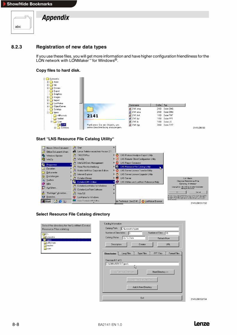
Appendix
8-8 L_^ONQN bk NKM
8.2.3 Registration of new data types
If you use these files, you will get more information and have higher configuration friendliness for theLON network with LONMakertfor Windows®.
Copy files to hard disk.
2141LON150
Start “LNS Resource File Catalog Utility“
2141LON151/152
Select Resource File Catalog directory
2141LON153/154

Appendix
8-9L _^ONQN bk NKM
Add new type directory
2141LON155/154
Click the buttons “Add a new directory” and “Refresh Now” .
8.3 List of abbreviations
Abbreviation Meaning
AIF Automation Interface; interface between controller and automation or fieldbus modules. It also includes defined process data.
EMC Electromagnetic Compatibility
DCB DC-injection brake
hex Display of values in the hexadecimal character format (0, �, 9, A, B, �, F ).
RFG Ramp-function generator; setpoint integrator
Imax Current limit
IMP Pulse inhibit
JOG Fixed speed or input for activation of the fixed speed
CRL Communication reference list
LSB Least Significant Bit; low-weighting bits of a binary value
Max-PDU Maximum Process Data Unit
MSB Most Significant Bit; high-weighting bits of a binary value
PO-data Process-output data
PC Personal Computer
PI-data Process-input data
PE Protective earth
PCD Process data,
QSP Quick stop
Ctrl. enable Controller enable
RS232 Interface standard
RS485 Interface standard with difference signals
Ctrl. inhibit Controller inhibit
TRIP Operation fault
Vcc Controlled constant voltage supply

Appendix
8-10 L_^ONQN bk NKM
8.4 Glossary
Technical term Meaning
Controller General term for servo drives, frequency inverters and DC drives
Baud rate Transmission speed of data in bit/s
Bus terminal Network node between long-distance and peripheral bus
Bus devices Unit which communicates with the host via the bus
code For input and display (access) of parameter values.
Code number/code Clear labelling of a parameter, e.g. C0106. For calculation information see Lenze code addressing in chapter„Parameter setting“,
Fieldbus For the exchange of data between higher-level controls (hosts) and positioning controls (e. g. controllers).
FTT Free Topology Transceiver.
Handshake Stipulated data-transfer method (here implemented by software).
Host PC or PLC
Master see host/host system
LON Logical Operating Network
Network topology Design and structure of a network: e.g. point-to-point network, line network, ring network)
Parameters Adjustable controller variables and values addressable via codes
Peripheral-bus module Bus participant in the peripheral bus
Peripheral-bus station Consists of bus terminal, peripheral-bus module and long-distance bus controller.
Icon Sign or symbol with an unambiguous message.
Process data, Small amounts of data for fast and cyclic transmission; e.g. setpoints and actual values
Process-data channel(PCD channel)
Communication channel for fast and cyclic transmission of process data
Acknowledgement Acknowledgement of a setting or change (e. g. of parameters))
Slave Bus participant which is only allowed to transmit data after a request by a master. For instance, controllersare slaves. (See Host/host system)
Application as directed:Appropriate use of the machine according to the manufacturer’s information or to common use because of itsdesign and function.inappropriateThe use of the machine which does not comply with the manufacturer’s declaration.
Cycle time The cycle time of the communication system is the time required for the exchange of all process databetween the host and the field units (e.g. controllers).
8.5 More information sources
No. Titel Published by1 Engineering Bulletin 170, LonTalk Response Time Measurements Echelon Corporation2 LonMark� Functional Profile: Variable Speed Motor Drive LONMARK Interoperability Association3 LonWorks� FTT-10A Free Topology Transceiver User’s Guide Echelon Corporation4 LonMaker� for Windows� User’s Guide Echelon Corporation

Appendix
8-11L _^ONQN bk NKM
8.6 Table of keywords
AAcceleration time, 6-19
Actual speed value, 6-6
AIF-CTRL, Device control, 6-2, 6-24
AIF-IN, Function block, 6-41
AIF-OUT, Function block, 6-38
Appendix, 8-1
Application as directed, 1-2
Application conditions, 3-1
BBasic insulation, 4-4
CCommissioning, 5-1
Communication interference, 4-4
Communication medium, 3-2
Communication times, 3-3
Configuration variableAcceleration time, 6-19Deceleration time, 6-20Description , 6-11Location label, 6-11Maximum Send Time, 6-13Maximum speed, 6-15Minimum Send Time, 6-14Minimum speed, 6-16Overview, 6-3Rated frequency, 6-18Rated speed value, 6-17Receive heartbeat for manufacturer-specific network variables,6-21Receive Heartbeat Time, 6-12
ConnectionExternal supply, 4-2Plug connector (2-pole), 4-2
Connection terminals, 4-2
Connector plug, LON bus, 4-2
Control word8200 vector, 6-30, 6-3382XX, 6-26, 6-2993XX, 6-37, 6-40
ControllerApplication as directed, 1-2Labelling, 1-2
Controller configuration , 5-2

Appendix
8-12 L_^ONQN bk NKM
D
Data types, Registration, 8-8
Deceleration time, 6-20
Definitions, 1-1
Description , Configuration variable VSD, 6-11
Device control
AIF-CTRL, 6-24Monitoring reaction, 6-22
VSD, 6-5
Dimensions, 3-2
Disposal, 1-2
E
Electrical data. Siehe Ratings
F
Fault elimination, 7-1
Fieldbus module, Order name, 3-1
First switch-on, 5-1
Frequency setpoint
8200 vector, 6-30
82XX, 6-26
Front view of the fieldbus module, 4-1
FTT, 3-2
Function module PROFIBUS-DP
Lenze parameters, 6-4
Parameters, Transmission, 6-1
Process data,, Transmission, 6-1
G
GDCWrapper.exe, 8-1
Glossary, 8-10
Siehe auch Glossary
I
Installation
Electrical, 4-4
Mechanical, 4-3
Wiring to a host, 4-4
LLabelling, Controller, 1-2
Legal regulations, 1-2
Lenze parameter sets, 6-2
Lenze parameters, Function module PROFIBUS-DP, 6-4
Liability, 1-2
ListAbbreviations, 8-9
Technical term. Siehe Glossary
List of abbreviations, 8-9
Location label, 6-11
LON network, Configuration, 8-3
LONMaker, Automatic GDC start, 8-1
LONMaker2GDC.exe, 8-1
MMains isolation, 4-4
Manufacturer, 1-2
Maximum Send Time, 6-13
Maximum speed, 6-15
Minimum Send Time, 6-14
Minimum speed, 6-16
Monitoring reaction, AIF-CTRL, 6-22
Motor current, 6-8
Motor voltage, 6-9
NNetwork variable, 8-5
AIF-CTRL8200 vector, 6-3082XX, 6-269300 Servo PLC, 6-4293XX, 6-35Drive PLC, 6-42Input variables, 6-25Output variables, 6-24
Overview, 6-2
VSDActual speed value, 6-6Motor current, 6-8Motor voltage, 6-9Operating time, 6-10Scaling of the speed setpoint, 6-7Speed setpoint, 6-5
Node Object, 6-1
Number of devices connected to the bus, 3-3

Appendix
8-13L _^ONQN bk NKM
O
Operating time, 6-10
Operator, 2-1
Overview
Configuration variable, 6-1, 6-3
Network variable, 6-1AIF-CTRL, 6-2VSD, 6-2
Node Object, 6-1
P
Parameter data channel, configuration, 6-2
Parameter sets, 6-2
Parameter setting, 6-1
Parameters
Control word (C0135)8200 vector, 6-3082XX, 6-26
Frequency setpoint (C0046)8200 vector, 6-3082XX, 6-26
L-C0142, 5-2
PE shield cable, 4-4
Personnel, Qualified, 2-1
Processing time in the basic unit, 3-3
R
Rated frequency, 6-18
Rated speed value, 6-17
Ratings, 3-2
Receive Heartbeat Time, 6-12
Registration, of data types, 8-8
SSafety information, 2-1
Layout, 2-2Other notes, 2-2Warning of material damage, 2-2Warning of personal damage, 2-2
Safetyinformation, Operating Instructions, 1-1
Scaling of the speed setpoint, 6-7
Scope ofsupply, 1-1
Service key, 4-1
Service LED, 4-1
SpeedMaximum, 6-15
Minimum, 6-16
Speed setpoint, 6-5Scaling, 6-7
Starting GDC, from LONMaker, 8-1
Status word, 82XX, 6-27
Switch-on sequence, First switch-on, 5-1
TTechnical data, 3-1
TechnicaldataCommunication times, 3-3
Dimensions, 3-2
Features of the fieldbus module, 3-1
General data/Application conditions, 3-1
Ratings, 3-2
Troubleshooting, 7-1
UUse, as directed, 1-2
VVoltage supply, 4-5
Voltage supply, external, 4-2
VSD, Device control, 6-2, 6-5
WWarranty, 1-2
Wiring, to a host, 4-4
Write parameter (example), 6-6

Appendix
8-14 L_^ONQN bk NKM