Embed Size (px)
Citation preview

Operating instructions
Maintenance instructions
Catalogue number008 104 31 07/2003
BW 80 AD-2 / BW 80 ADH-2
BW 90 AD-2 / BW 100 ADM-2
BW 90 AC-2 / BW 80 ADSS/N 101 460 42 0101 S/N 101 460 62 0101S/N 101 460 52 0101 S/N 101 460 72 0101
S/N 101 460 73 0101
Tandem vibratory/combination roller
Side-free tandem roller


Foreword
F orewordBOMAG machines are products from the wideproduct range of BOMAG compaction equip-ment.
The vast experience of BOMAG as well asmodern production and testing methods suchas lifetime tests of all important componentsand most stringent quality demands ensurehighest reliability of the machine.
These instructions comprise:
l Safety regulations
l Operating instructions
l Maintenance instructions
l Trouble shooting
Using these instructions will
l help to become acquainted with the machine.
l avoid malfunctions caused by unprofessionaloperation.
Compliance with the maintenance instructions will
l increase the reliability when being used on aconstruction site
l prolong the lifetime of the machine,
l reduce repair costs and downtimes.
BOMAG will not assume liability for the correctfunction of the machine
l if the operation is not in accordance with theoperating instructions,
l if it is used for purposes other than the ones itis determined for (see safety regulations).
No warranty claims can be lodged for damage re-sulting from
l operating errors,
l insufficient maintenance and
l the use of wrong fuels and lubricants.
Please note!
This manual was written for operators and mainte-nance personnel on construction sites.
Make sure that these instructions are always closeat hand, e.g. in the tool compartment of the ma-chine or in the specially provided container. Theoperating and maintenance instruction manual ispart of the machine.
You should only operate this machine after youhave been instructed and by observing these in-structions.
Please observe strictly the safety regulations.
Please observe also the guidelines of the civil en-gineering liability association "safety regulationsfor the operation of road rollers and soil compac-tors" as well as the relevant accident preventionregulations.
For your own safety you should only use gen-uine BOMAG spare parts.
We reserve the right for technical modifica-tions without prior notification.
These operating and maintenance instructions arealso available in other languages.
The spare parts catalogue and the repair instruc-tions are available from your BOMAG dealeragainst the serial number of your machine.
You can also obtain information about the correctuse of our machines for asphalt applications fromyour BOMAG dealer.
The above mentioned or following notes do notconstitute an extension or replacement of the gen-eral terms of business of BOMAG.
We wish you successful work with your BOMAGmachine.
BOMAG GmbH
Printed in Germany
Copyright by BOMAG
BOMAG 3BW 80 AD-2 Fam.

Foreword
Please fill in
. . . . . . . . . . . . . . . . . . . . . . . . . . . .
Machine type (Fig. 1)
. . . . . . . . . . . . . . . . . . . . . . . . . . . .
Serial No. (Fig. 1 and 2)
. . . . . . . . . . . . . . . . . . . . . . . . . . . .
Engine type (Fig. 3)
. . . . . . . . . . . . . . . . . . . . . . . . . . . .
Engine No. (Fig. 3)
i Note
Fill in the above listed data when receiving the ma-chine.
Upon receipt of the machine our organization willinstruct you about correct operation and mainte-nance.
Please observe strictly all safety regulations andnotes on potential dangers!
Fig. 1
Fig. 2
Fig. 3
BOMAG4 BW 80 AD-2 Fam.

Table of Contents
Technical Data 7
Safety regulations 15
Indicators and Controls 23
3.1 General notes 27
3.2 Description of indicators and control elements 27
Operation 35
4.1 General notes 36
4.2 Tests before taking into operation 36
4.3 Starting the engine 37
4.4 Starting at low temperatures 39
4.5 Starting with jump leads 41
4.6 Driving the machine 41
4.7 Operating the parking brake, stopping the machine 43
4.8 Switching the vibration on and off 44
4.9 Switching the gravity sprinkler system on or off 46
4.10 Switching the pressure sprinkling system on and off 46
4.11 Checking the sprinkling system with the machine stopped 47
4.12 Switching the tire sprinkler system in or off 47
4.13 Stopping the engine/machine 48
4.14 Adjusting the operator's seat 49
4.15 Towing 50
4.16 Loading and transport 51
Maintenance 53
5.1 General notes on maintenance 54
5.2 Fuels and lubricants 55
5.3 Table of fuels and lubricants 58
5.4 Running-in instructions 59
5.5 Maintenance chart 60
5.6 Checking the engine oil level 62
5.7 Checking the fuel level 62
5.8 Check the hydraulic oil level 63
5.9 Checking the hydraulic oil filter element 63
5.10 Checking the coolant level 64
5.11 Checking the water level 64
5.12 Checking the emulsion level (BW 90 AC-2) 65
5.13 Cleaning the scrapers 65
5.14 Greasing the articulated joint 66
5.15 Checking the tire pressure 66
5.16 Checking, cleaning, changing the dry air filter cartridge 67
5.17 Changing the engine oil 69
5.18 Change the engine oil filter 70
BOMAG 5BW 80 AD-2 Fam.

Table of Contents
5.19 Checking the condition, tension of the V-belt, changing the V-belt 71
5.20 Checking the condition and tension of the toothed belt for the pump drive72
5.21 Changing the fuel precleaner, bleeding the fuel system 73
5.22 Cleaning the cooling fins on radiator and hydraulic oil cooler 74
5.23 Cleaning the water sprinkler system 76
5.24 Changing the main fuel filter 77
5.25 Draining the fuel tank sludge 77
5.26 Checking the condition of the battery 78
5.27 Checking, adjusting the valve clearance 80
5.28 Changing the hydraulic oil 82
5.29 Changing the hydraulic oil filter element 83
5.30 Changing the coolant 84
5.31 Replacing the pump drive toothed belt 85
5.32 Replacing the dry air filter cartridge 87
5.33 Water sprinkler system, maintenance in the event of frost 88
5.34 Tightening torques for screws with metric unified thread 88
5.35 Engine conservation 89
Trouble shooting 91
6.1 General notes 92
6.2 Engine 93
BOMAG6 BW 80 AD-2 Fam.

BW 80 AD-2 Fam.
1 Technical Data
BOMAG 7

Technical Data
Fig. 4
Dimensions inmm
A B C D H H2 K L O1/O2 S W
BW 80 AD/ADH-2
1282 856 458 580 1482 2300 250 1862 28 13 800
BW 90 AD-2 1282 956 458 580 1482 2300 250 1862 28 12 900
BW 100 ADM-2 1282 1056 458 580 1482 2300 250 1862 28 12 1000
* BW 80 AD-2 BW 80 ADH-2 BW 90 AD-2 BW 100ADM-2
WeightsBasic weight kg 1335 1485 1385 1435Operating weight (CECE) kg 1470 1620 1520 1570Mean axle load (CECE) kg 735 810 760 785Mean static linear load kg/cm 9,2 10,1 8,4 7,9
DimensionsWorking width mm 800 800 900 1000Outer track radius mm 2820 2820 2870 2920Length with ROPS mm 1934 1934 1934 1934
BOMAG8 BW 80 AD-2 Fam.
Technical Data
Travel characteristicsTravel speed (1) km/h 0 to 4,5 0 to 4,5 0 to 4,5 0 to 4,5Travel speed (2) km/h 0 to 8 0 to 8 0 to 8 0 to 8Max. gradability without/with vibration (soil de-pendent)
% 40/30 40/30 40/30 40/30
DriveEngine manufacturer/type Kubota D 722
BCooling WaterNumber of cylinders 3Rated power ISO 9249 kW (PS) 11,9 (16)Rated speed 1 rpm 3000Battery V/AH 12/50Drive system hydrostaticDriven axles front+rear
BrakesService brake hydrostaticParking brake hydrost.
mechanical
SteeringType of steering Oscill.-articul.Steering operation hydrostaticSteering/oscillation angle Degree 31/6
Vibration systemVibrating drum front+rear front+rear front+rear front+rearDrive system hydrostatic hydrostatic hydrostatic hydrostaticFrequency Hz 60/40 60/40 60/40 60/40Amplitude mm 0,5 0,5 0,5 0,5Centrifugal force kN 15 15 15 15
Water sprinkler systemType of sprinkling Gravity, pres-
sure sprinklingwith interval**
Filling capacitiesFuel (diesel) l 23Water l 100Hydraulic oil l 9* The right for technical modifications remains reserved** Optional equipment
* BW 80 AD-2 BW 80 ADH-2 BW 90 AD-2 BW 100ADM-2
BOMAG 9BW 80 AD-2 Fam.

Technical Data
Fig. 5
Dimensions inmm
A B C D H H2 K L O1/O2 S W
BW 90 AC-2 1282 956 458 580 1562 2380 250 1870 28 12 900
* BW 90 AC-2
WeightsBasic weight kg 1530Operating weight (CECE) kg 1670Mean axle load (CECE),drum
kg 701
Mean axle load (CECE),wheels
kg 969
Mean static linear load kg/cm 7,8
DimensionsWorking width mm 900/860Outer track radius mm 2870Length with ROPS mm 1985
BOMAG10 BW 80 AD-2 Fam.

Technical Data
Travel characteristicsTravel speed (1) km/h 0 to 4,5Travel speed (2) km/h 0 to 8Max. gradability without/with vibration (soil de-pendent)
% 40/30
DriveEngine manufacturer/type Kubota D 722 BCooling WaterNumber of cylinders 3Rated power ISO 9249 kW (PS) 11,9 (16)Rated speed 1 rpm 3000Battery V/AH 12/50Drive system hydrostaticDriven axles front+rear
BrakesService brake hydrostaticParking brake hydrost. - mechanical
SteeringType of steering Oscill.-articul.Steering operation hydrostaticSteering/oscillation angle Degree 31/6
Vibration systemVibrating drum frontDrive system hydrostaticFrequency Hz 60/40Amplitude mm 0,5Centrifugal force kN 15
Water sprinkler systemType of sprinkling Pressure sprinkling with interval
Filling capacitiesFuel (diesel) l 23Water l 100Emulsion l 10Hydraulic oil l 9* The right for technical modifications remains reserved
* BW 90 AC-2
BOMAG 11BW 80 AD-2 Fam.
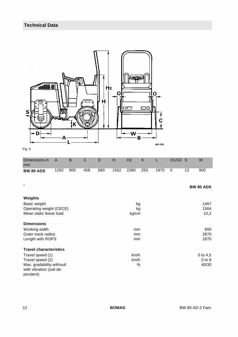
Technical Data
Fig. 6
Dimensions inmm
A B C D H H2 K L O1/O2 S W
BW 80 ADS 1282 900 458 580 1562 2380 250 1870 0 13 900
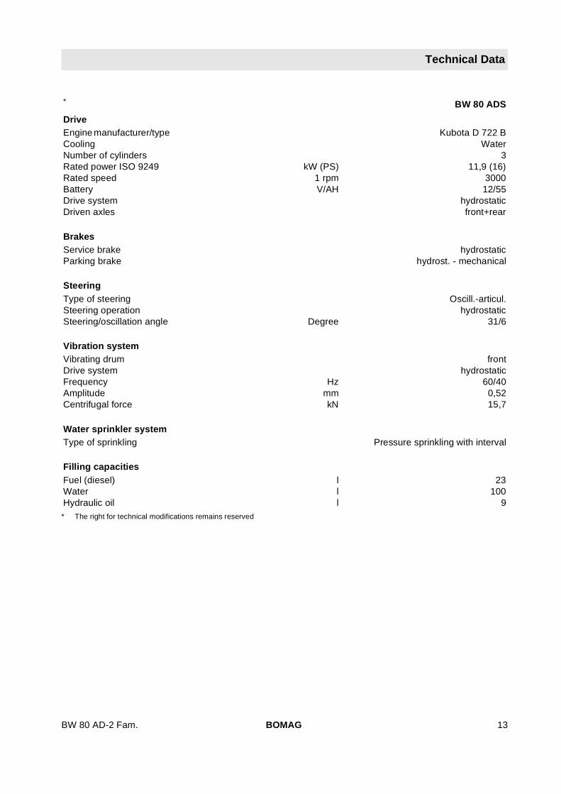
* BW 80 ADS
WeightsBasic weight kg 1467Operating weight (CECE) kg 1564Mean static linear load kg/cm 10,2
DimensionsWorking width mm 800Outer track radius mm 2870Length with ROPS mm 1870
Travel characteristicsTravel speed (1) km/h 0 to 4,5Travel speed (2) km/h 0 to 8Max. gradability without/with vibration (soil de-pendent)
% 40/30
BOMAG12 BW 80 AD-2 Fam.
Technical Data
DriveEngine manufacturer/type Kubota D 722 BCooling WaterNumber of cylinders 3Rated power ISO 9249 kW (PS) 11,9 (16)Rated speed 1 rpm 3000Battery V/AH 12/55Drive system hydrostaticDriven axles front+rear
BrakesService brake hydrostaticParking brake hydrost. - mechanical
SteeringType of steering Oscill.-articul.Steering operation hydrostaticSteering/oscillation angle Degree 31/6
Vibration systemVibrating drum frontDrive system hydrostaticFrequency Hz 60/40Amplitude mm 0,52Centrifugal force kN 15,7
Water sprinkler systemType of sprinkling Pressure sprinkling with interval
Filling capacitiesFuel (diesel) l 23Water l 100Hydraulic oil l 9* The right for technical modifications remains reserved
* BW 80 ADS
BOMAG 13BW 80 AD-2 Fam.

Technical Data
The following noise and vibration values according to the EC-directive for machines, edition (98/37/EEC) and the noise emission regulation 2000/14/EC were measured at nominal engine speed and withthe vibration switched on. The machine was standing on an elastic base.
During operation these values may vary because of the existing operating conditions.
Noise valueThe sound level according to enclosure 1, paragraph 1.7.4. f of the EC-machine regulation is
sound pressure level on the operator’s stand:
BW 80 AD-2
LpA =84,3 dB(A)
BW 90 AC-2
LpA =82,2 dB(A)
BW 90 AD-2
LpA =83,8 dB(A)
BW 100 ADM-2
LpA =82,3 dB(A)
The nose emission value for the machine according to the noise emission regulation 2000/14/EG is
guaranteed sound capacity level of the machine:
BW 80 AD-2
LWA = 102 dB(A)
BW 90 AD-2, BW 90 AC-2, BW 100 ADM-2
LWA = 102 dB(A)
These sound values were determined according to ISO 3744 for the sound capacity level (LWA) and ISO11204 for sound pressure level (LpA) at the place of the operator.
Vibration valueThe vibration values according to enclosure 1, paragraph 3. 6. 3. a of the EC-machine regulation are:
Vibration of the entire boy (driver’s seat)
The weighted effective acceleration value determined according to ISO 7096 is <= 0.5 m/sec2.
Hand-arm vibration values
The weighted effective acceleration value determined according to EN 500/ISO is <= 2.5 m/sec2.
BOMAG14 BW 80 AD-2 Fam.

BW 80 AD-2 Fam.
2 Safety regulations
BOMAG 15
Safety regulations
General Notes
This BOMAG machine has been built in ac-cordance with the latest technical standardand complies with the applicable regulationsand technical rules. However, dangers for per-sons and property may arise from this ma-chine, if:
l it is used for purposes other than the ones it isintended for
l it is operated by untrained personnel
l it is changed or converted in an unprofessionalway
l the safety instructions are not observed
Each person involved in the operation, mainte-nance and repair of the machine must there-fore read and comply with these safetyregulations. If necessary, this must be con-firmed by obtaining the signature of the cus-tomer.
Furthermore, the following instructions and regula-tions must obviously also be complied with:
l applicable accident prevention instructions
l generally accepted safety and road traffic reg-ulations
l country specific safety regulations. It is theduty of the operator to be acquainted withthese instructions and to apply these accord-ingly. This applies also for local regulationsconcerning different types of handling work.Should the recommendations in these instruc-tions be different from the regulations valid inyour country, you must comply with the safetyregulations valid in your country.
Intended useThis machine must only be used for:
l compaction of bituminous material, e.g. roadsurface layers. (Only AC and AD machines)
l medium to heavy compaction work in earthconstruction (road sub-bases)
l You should only operate the unit with fullyfunctional safety equipment.
l Have the machine inspected by an expertonce every year.
Unintended useHowever, dangers may arise from this machine ifit is operated by untrained personnel or if it is sub-ject of unintended use.
Do not work with vibration on hard concrete, curedbitumen layers or extremely frozen ground.
Starting and operation of the machine in explosiveenvironments is prohibited.
Who has permission to operate the ma-chine?Only trained and instructed persons of at least 18years of age are permitted to drive and operatethis machine. For operation of the machine the re-sponsibilities must be clearly specified and com-plied with.
Persons under the influence of alcohol, medicineor drugs are not allowed to operate, service or re-pair the machine.
Maintenance and repair work requires specificknowledge and must therefore only be performedby trained specialists.
Conversions and changes to the ma-chineUnauthorized alterations to the machine are pro-hibited for safety reasons.
Original parts and accessories have been special-ly designed for this machine. We wish to make ex-plicitly clear that we have not tested or approvedany parts or accessories not supplied by us. Theinstallation and/or use of such products may havean adverse effect on the active and/or passivedriving safety. The manufacturer explicitly ex-cludes any liability for damage caused by the useof non-original parts or accessories.
Notes on safety in the operating andmaintenance instructions:
! Danger
Paragraphs marked like this highlight possibledangers for persons.
! Caution
Paragraphs marked like this highlight possibledangers for machines or parts of the machine.
BOMAG16 BW 80 AD-2 Fam.
Safety regulations
i Note
Paragraphs marked like this contain technical in-formation for the optimal economical use of themachine.
Environment
Paragraphs marked like this point out practic-es for safe and environmental disposal of fuelsand lubricants as well as replacement parts.
Observe environmental regulations.
Information and safety stickers/decalson the machineKeep safety stickers in good and legible condition(see parts manual) and comply with their meaning.
Replace damaged and illegible stickers/decals.
Loading the machineAlways check the fastening of the central liftinghook before attempting to lift the machine.
Use only strong and stable loading ramps. Theramp inclination must not exceed the gradability ofthe machine.
Secure the machine against turning over or slip-ping off.
Secure the machine on the transport vehicleagainst rolling, sliding and tipping over.
Persons are highly endangered if
l they step or stand under loads being lifted
l they remain in the drive range of the machineduring a demonstration or during loading.
The machine must not swing about when lifted offthe ground.
Use only safe lifting gear of sufficient load bearingcapacity.
Attach the lifting gear only to the specified liftingpoints.
Towing the machineYou should generally use a tow bar.
Max. towing speed 1 km/h, max. towing distance500 m.
Before releasing the multi-disc brake secure themachine against unintended rolling.
Checking the roll over protectionstructure (ROPS)The frame of the machine must not be warped,bent or cracked in the area of the ROPS fastening.
The ROPS must not show any rust, damage, hair-line cracks or open fractures.
The ROPS must not rattle about when driving.This would indicate that it is not properly fastened.All bolted connections must comply with the spec-ifications and should be absolutely tight (observethe tightening torques). Screw and nuts must notbe damaged, bent or deformed.
No accessories may be welded or bolted on andno additional holes must be drilled without the con-sent of the distributor, since this will impair thestrength of the unit.
Starting the machine
Before starting
The machine must only be operated from the driv-er's seat.
Use only machines which are serviced at regularintervals.
Become acquainted with the equipment, the con-trol elements, the working principle of the machineand the working area.
Wear your personal protective outfit (hard hat,safety boots, etc.).
Before climbing on the machine check whether:
l persons or obstructions are beside or underthe machine
l the machine is free of oily and combustiblematerial
l all grips, steps and platforms are free ofgrease, oils, fuel, dirt, snow and ice
l the engine hood is closed and locked
Use steps and grips to climb onto the machine.
Before starting the machine check whether:
l the machine shows any obvious faults
l all guards and safety elements are in place
l steering, brakes, control elements, light sys-tem and warning horn work correctly
BOMAG 17BW 80 AD-2 Fam.

Safety regulations
l the seat is correctly adjusted
l mirrors (if present) are clean and correctly ad-justed.
Do not start the machine with defective gauges,control lights or control elements.
Do not take any loose objects with you or fastenthem to the machine.
On machines with roll over protection system youmust always wear your seat belt.
Starting
Start and operate the machine only from the driv-er's seat.
For starting set all control levers to 'neutral posi-tion'.
Do not use any starting aids like start pilot or ether.
After starting check all gauges and control lights.
Starting with jump wires
Connect plus with plus and minus with minus(ground cable) - always connect the ground straplast and disconnect it first! A wrong connection willcause severe damage in the electric system.
Do not start the engine by shorting the electric ter-minals on the starter motor, because the machinemay start to drive immediately.
Starting in closed rooms
Exhaust gases are highly dangerous! Always en-sure an adequate supply of fresh air when startingin closed rooms!
Driving the machine
Persons in the endangered area
Before starting or resuming work and especiallywhen reversing, check that there are not any per-sons or obstructions in the endangered area.
If necessary give warning signals. Stop work im-mediately if persons remain in the danger area de-spite the warning.
Do not step or stand in the articulation area of themachine when the engine is running. Risk ofsquashing!
Driving
In events of an emergency operate the emergencystop switch immediately. Do not use the emergen-cy stop switch as a service brake.
Restart the machine only after the danger, that hascaused the actuation of the emergency stop, hasbeen eliminated.
If the machine has come in contact with high-volt-age power lines:
l do not leave the operator's stand
l warn others from coming too close to the ma-chine or touching it
l if possible drive the machine out of the dangerzone
l have the power shut off
Operate the machine only from the operator'sseat.
Do not adjust the seat while driving.
Do not climb onto or off the machine while driving.
Change the travel direction only while the machineis standing.
Do not use the machine to transport persons.
Stop the machine if you notice unusual noises orthe development of smoke. Investigate the causeand have the fault corrected.
Keep a sufficient distance to excavations and em-bankments and make sure that your work does notimpair the stability of the machine.
Do not work with vibration on hard concrete, on acured bitumen surface or heavily frozen ground.
When passing under flyovers, bridges, tunnels,electric power lines etc. keep a sufficient distance.
Driving on slopes and gradients
Do not drive up and down gradients, which exceedthe max. gradability of the machine.
Always drive extremely carefully on slopes and al-ways straight up and down the slope. Change tothe lower speed range before approaching theslope.
Wet and loose soils reduce the ground adhesion ofthe machine on gradients and slopes. Higher riskof accident!
Behaviour in traffic
Match the speed of the machine to the workingconditions.
Always allow loaded transport vehicles to pass.
Switch the lights on when the visibility is poor.
Keep clear of edges and embankments.
BOMAG18 BW 80 AD-2 Fam.

Safety regulations
Check the effect of vibration
When compacting with vibration check the effectof the vibration on nearby buildings and under-ground supply lines (gas, water, sewage, electricpower supply), stop vibratory compaction if neces-sary.
Do not activate the vibration on hard (frozen, con-crete) ground. Risk of bearing damage!
Parking the machinePark the machine on level and firm ground.
Before leaving the machine:
l return the travel lever to neutral position
l apply the parking brake
l shut the engine down and pull the ignition keyout
l secure the machine against unauthorized use.
Do not jump off the machine, use access stepsand hand rails.
Always secure parked machines, which could bein the way, with appropriate measures.
Parking on slopes and gradients
Secure the machine against rolling, place metalchocks in front of and behind the drums.
Filling the fuel tankDo not inhale fuel fumes.
Refuel only after shutting the engine and the aux-iliary heater down.
Do not refuel in closed rooms.
No open fire, do not smoke.
Do not spill any fuel. Catch running out fuel, do notlet it seep into the ground.
Wipe off spilled fuel. Keep dirt and water awayfrom fuel.
Leaking fuel tanks can cause explosions. Ensuretight fit of the fuel tank lid, replace immediately ifrequired.
Fire protection measures
Become acquainted with the location and the han-dling of fire extinguishers. Observe all fire alarmand fire fighting possibilities.
MaintenanceObserve the maintenance tasks described in theoperating and maintenance instructions, includingthe exchange of parts.
Maintenance work must only be carried out byqualified and authorized personnel.
For overhead service and assembly work use theprovided access installations or any other safe ac-cess ladders and work platforms. Do not use ma-chine parts as access steps.
Keep unauthorized persons away from the ma-chine.
Do not perform maintenance work with the ma-chine driving or the engine running.
Park the machine on horizontal, level and stableground.
Pull the key out of the ignition switch.
Lock the articulated joint with the articulation lock.
Working on hydraulic lines
Always depressurize the hydraulic lines beforestarting to work on them. Hydraulic oil escapingunder pressure can penetrate the skin and causesevere injury. If injured by hydraulic oil seek med-ical advice immediately as otherwise severe infec-tions may result.
When adjusting the hydraulic system do not standbehind or in front of the drum/wheels.
Do not change the setting of high pressure reliefvalves.
Drain hydraulic oil at operating temperature - dan-ger of scalding!
Catch running out hydraulic oil and dispose of en-vironmentally.
Always catch and dispose of biological hydraulicoils separately.
Do not start the engine after draining off the hy-draulic oil.
After finishing work (with the system still depressu-rized!) check all connections and fittings for leaks.
Changing hydraulic hoses
All hydraulic hoses must be inspected visually atregular intervals.
Hydraulic hoses must be changed immediately if:
l the outer layer is worn down to the metal lining(e.g. chafing, cuts, cracks)
BOMAG 19BW 80 AD-2 Fam.

Safety regulations
l embrittlement of the outer layer (developmentof cracks in the hose material)
l deformation under pressurized and depressu-rized condition, which are not in accordancewith the normal shape of the hydraulic hose
l deformation in bends, e.g., squeezes, kinks,layer separation, formation of blisters
l leakages.
l non-observance of the installation require-ments.
l separation of the hydraulic hose from the fit-ting
l corrosion of the fitting, which impairs the func-tion and the strength.
l Do not mix up hoses by mistake.
l damage or deformation of the fitting, which im-pairs the function and strength of the hose/hose connection.
Only genuine BOMAG hydraulic hoses ensurethat the correct type of hose (pressure range) isused at the right place.
Working on the engine
Shut the engine down before opening the enginecompartment hood.
Drain the engine oil at operating temperature -danger of scalding!
Wipe off spilled oil, catch running out oil and dis-pose of environmentally.
Store used filters and other oily materials in a sep-arate, specially marked container and dispose ofenvironmentally.
Do not leave any tools or other objects, whichcould cause damage, in the engine compartment.
Check and change the coolant only when the en-gine is cold.
Catch the coolant and dispose of environmentally.
Working on electrical equipment
Before working on electrical equipment disconnectthe battery and cover it with insulating material.
Do not use any fuses with higher Ampere ratingsand do not repair fuses with a piece of wire. Firehazard!
Always disconnect the battery before starting toweld on the machine.
Working on the battery
When working on the battery do not smoke, noopen flames!.
Do not let your hands or clothes come in contactwith acid. In case of injuries caused by acid, flushoff with clear water and consult a doctor.
Metal objects (e.g. tools, rings, wrist watches)must not contact the battery poles - danger ofshort circuit and burns!
When recharging maintenance free batteries re-move the plugs to avoid the accumulation of explo-sive gases.
When using an external battery to start the ma-chine follow the respective instructions.
Dispose of old batteries environmentally.
Switch the charging current off before removingthe charge clamps.
Ensure good ventilation, especially when chargingthe battery in a closed room.
Working on the fuel system
Do not inhale fuel fumes.
No open fire, do not smoke, do not spill any fuel.
Catch running out fuel, do not let it seep into theground and dispose of environmentally.
Working on wheels and tires
Explosion-like bursting of tires and parts of rimsand tires can cause severe or even deadly injuries.
You should only assemble tires if you have thenecessary experience and with the proper equip-ment. If necessary have the tires mounted by aspecialised workshop.
Ensure correct tire pressure and do not exceed thehighest specified pressure.
Check tires and wheels every day for pressuredrop, cuts, bulges, damaged rims, missing wheelstuds and nuts. Do not drive with damaged tires orwheels.
Non-sticking emulsions for tires must only bemade up of a mix of water and a concentrated anti-stick agent according to the instructions of themanufacturer. Observe the regulations for the pro-tection of the environment.
Cleaning
Do not clean the machine while the engine is run-ning.
BOMAG20 BW 80 AD-2 Fam.

Safety regulations
Do not use gasoline or other combustible sub-stances for cleaning purposes.
When using steam cleaning equipment do notsubject electrical components and insulating ma-terials to the direct water jet, but cover them be-forehand.
l Do not guide the water jet into the exhaust orinto the air filter.
After maintenance work
Reinstall all protective devices after completingthe maintenance work.
RepairMark a defective machine by attaching a warningtag to the steering wheel.
Repair work must only be performed by qualifiedand authorized persons. Use our repair instruc-tions for this work.
Exhaust gases are highly dangerous! Always en-sure an adequate supply of fresh air when startingin closed rooms!
Test
The safety of compaction equipment must bechecked by a specialist as required in dependenceon the application and the operating conditions,however at least once every year.
BOMAG 21BW 80 AD-2 Fam.

Safety regulations
BOMAG22 BW 80 AD-2 Fam.

BW 80 AD-2 Fam.
3 Indicators and Controls
BOMAG 23

Indicators and Controls
Fig. 7
BOMAG24 BW 80 AD-2 Fam.
Indicators and Controls
Fig. 8
BOMAG 25BW 80 AD-2 Fam.

Indicators and Controls
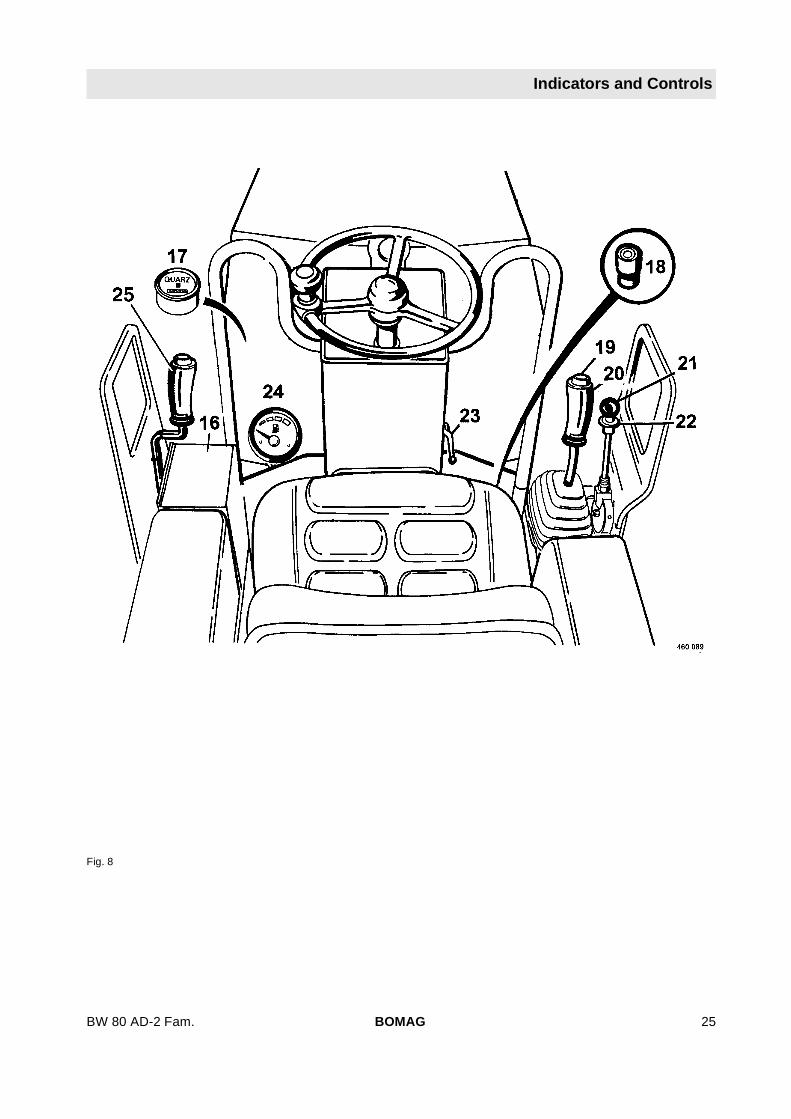
1 Preheating control light
2 Oil pressure warning light
3 Coolant temperature warning light
4 Charge control light
5 Emergency stop switch
6 Ignition switch
7 Sprinkler system interval switch*
8 Rotary switch for sprinkler system
9 Parking brake warning light
10 Warning light for seat contact switch
11 Rotary switch for lighting acc. to StVZO* orworking lights*
12 Rotary switch for hazard light system*
13 Rotary switch for direction indicators*
14 Rotary switch for flashing beacon*
15 Push button for warning horn
16 Fuse box
17 Operating hour meter (in engine compartment)
18 Foot switch for tire sprinkling system (only AC)
19 Push button for vibration
20 Travel lever
21 Throttle lever
22 Locking plate for throttle lever
23 Cock valve for rear vibration shut off
24 Fuel level gauge (in engine compartment)
25 Additional travel lever** Option
BOMAG26 BW 80 AD-2 Fam.

Indicators and Controls
3.1 General notes
Please read this section thoroughly before operat-ing this machine if you are not yet conversant withthe indicators and control elements. All functionsare described in detail hereunder.
Paragraph 4 "Operation" contains only concise de-scriptions of the individual operating steps.
3.2 Description of indicatorsand control elements
Fig. 9
No. 1 = Preheating control light
lights up = for approx. 6 seconds with theignition switch (6) in position"II".
goes out = after approx. 6 seconds withthe ignition switch in position"II", at this point start the en-gine immediately.
Fig. 10
No. 2 = Oil pressure warning light
lights up = with the ignition switch in posi-tion "I" (test) in case of insuffi-cient oil pressure the enginewill be shut down immediately.
goes out = after starting the engine
BOMAG 27BW 80 AD-2 Fam.
Indicators and Controls
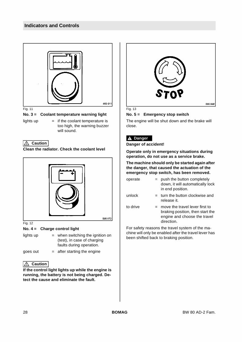
Fig. 11
No. 3 = Coolant temperature warning light
lights up = if the coolant temperature istoo high, the warning buzzerwill sound.
! Caution
Clean the radiator. Check the coolant level
Fig. 12
No. 4 = Charge control light
lights up = when switching the ignition on(test), in case of chargingfaults during operation.
goes out = after starting the engine
! Caution
If the control light lights up while the engine isrunning, the battery is not being charged. De-tect the cause and eliminate the fault.
Fig. 13
No. 5 = Emergency stop switch
The engine will be shut down and the brake willclose.
! Danger
Danger of accident!
Operate only in emergency situations duringoperation, do not use as a service brake.
The machine should only be started again afterthe danger, that caused the actuation of theemergency stop switch, has been removed.
operate = push the button completelydown, it will automatically lockin end position.
unlock = turn the button clockwise andrelease it.
to drive = move the travel lever first tobraking position, then start theengine and choose the traveldirection.
For safety reasons the travel system of the ma-chine will only be enabled after the travel lever hasbeen shifted back to braking position.
BOMAG28 BW 80 AD-2 Fam.
Indicators and Controls
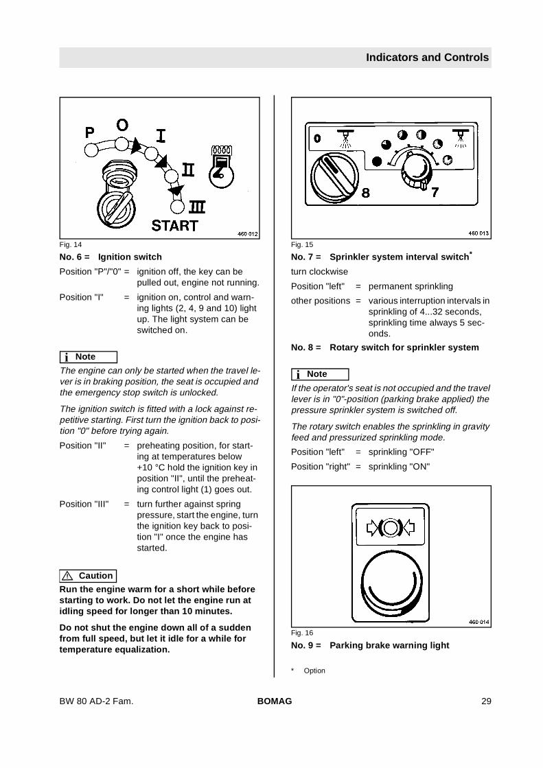
Fig. 14
No. 6 = Ignition switch
Position "P"/"0" = ignition off, the key can bepulled out, engine not running.
Position "I" = ignition on, control and warn-ing lights (2, 4, 9 and 10) lightup. The light system can beswitched on.
i Note
The engine can only be started when the travel le-ver is in braking position, the seat is occupied andthe emergency stop switch is unlocked.
The ignition switch is fitted with a lock against re-petitive starting. First turn the ignition back to posi-tion "0" before trying again.
Position "II" = preheating position, for start-ing at temperatures below+10 °C hold the ignition key inposition "II", until the preheat-ing control light (1) goes out.
Position "III" = turn further against springpressure, start the engine, turnthe ignition key back to posi-tion "I" once the engine hasstarted.
! Caution
Run the engine warm for a short while beforestarting to work. Do not let the engine run atidling speed for longer than 10 minutes.
Do not shut the engine down all of a suddenfrom full speed, but let it idle for a while fortemperature equalization.
Fig. 15
No. 7 = Sprinkler system interval switch*
turn clockwise
Position "left" = permanent sprinkling
other positions = various interruption intervals insprinkling of 4...32 seconds,sprinkling time always 5 sec-onds.
No. 8 = Rotary switch for sprinkler system
i Note
If the operator's seat is not occupied and the travellever is in "0"-position (parking brake applied) thepressure sprinkler system is switched off.
The rotary switch enables the sprinkling in gravityfeed and pressurized sprinkling mode.
Position "left" = sprinkling "OFF"
Position "right" = sprinkling "ON"
Fig. 16
No. 9 = Parking brake warning light
* Option
BOMAG 29BW 80 AD-2 Fam.
Indicators and Controls
lights up = with the ignition switch in posi-tion "I" (Test) with the travel le-ver in "0"-position the parkingbrake is applied.
goes out = when moving the travel leverout of neutral position and sit-ting down on the operator'sseat. Parking brake released.
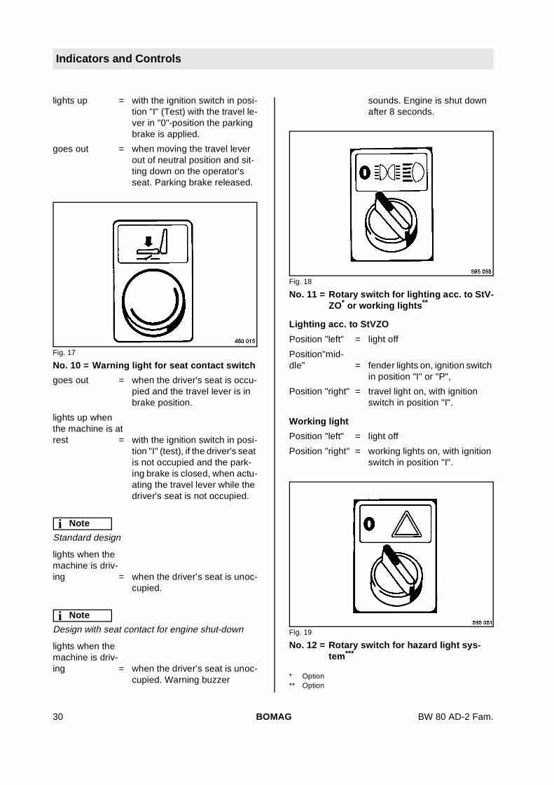
Fig. 17
No. 10 = Warning light for seat contact switch
goes out = when the driver's seat is occu-pied and the travel lever is inbrake position.
lights up whenthe machine is atrest = with the ignition switch in posi-
tion "I" (test), if the driver's seatis not occupied and the park-ing brake is closed, when actu-ating the travel lever while thedriver's seat is not occupied.
i Note
Standard design
lights when themachine is driv-ing = when the driver’s seat is unoc-
cupied.
i Note
Design with seat contact for engine shut-down
lights when themachine is driv-ing = when the driver’s seat is unoc-
cupied. Warning buzzer
sounds. Engine is shut downafter 8 seconds.
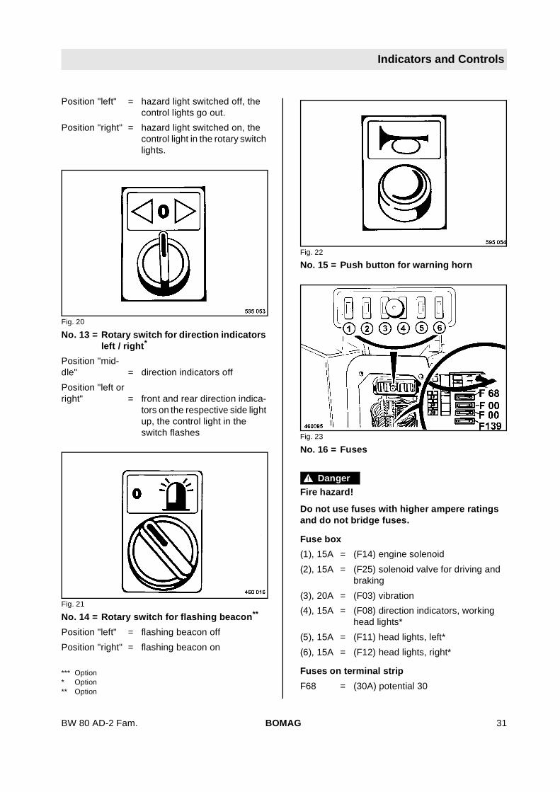
Fig. 18
No. 11 = Rotary switch for lighting acc. to StV-ZO* or working lights**
Lighting acc. to StVZO
Position "left" = light off
Position"mid-dle" = fender lights on, ignition switch
in position "I" or "P",
Position "right" = travel light on, with ignitionswitch in position "I".
Working light
Position "left" = light off
Position "right" = working lights on, with ignitionswitch in position "I".
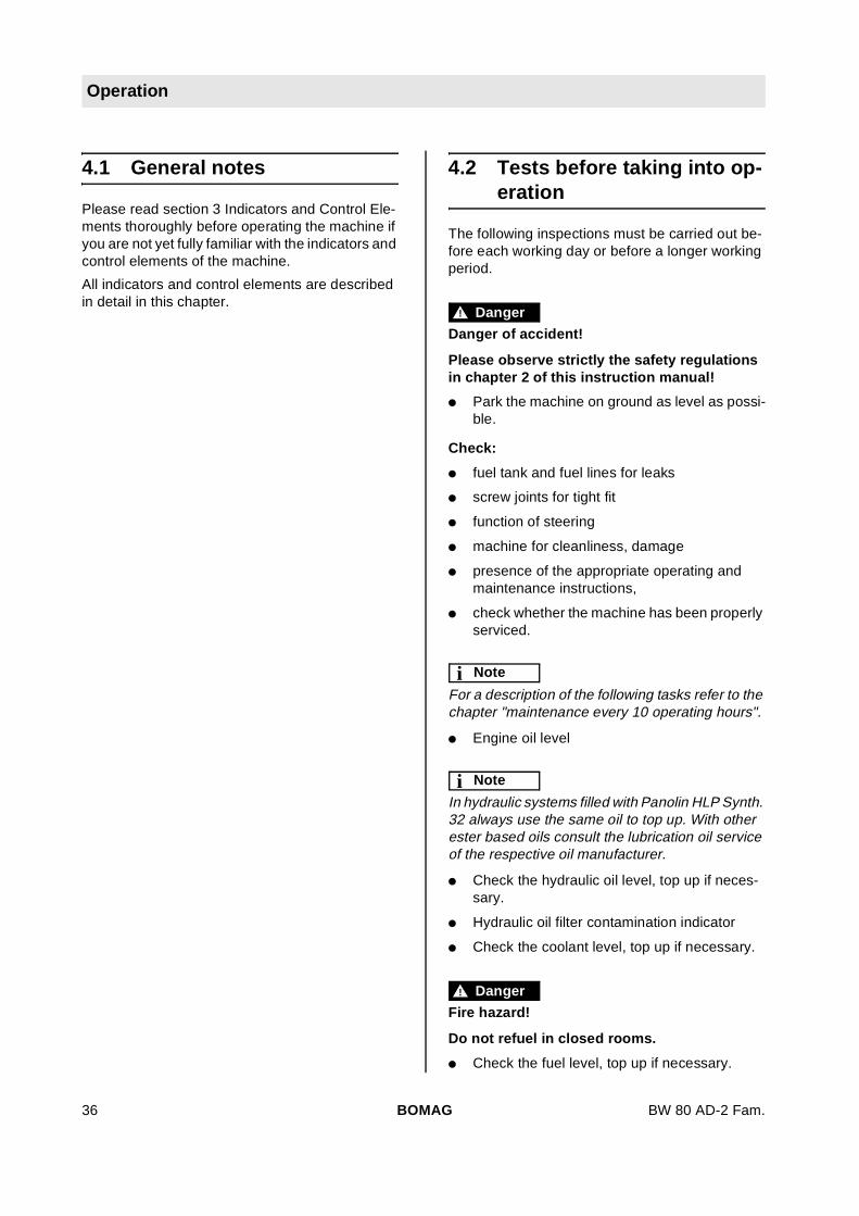
Fig. 19
No. 12 = Rotary switch for hazard light sys-tem***
* Option** Option
BOMAG30 BW 80 AD-2 Fam.
Indicators and Controls
Position "left" = hazard light switched off, thecontrol lights go out.
Position "right" = hazard light switched on, thecontrol light in the rotary switchlights.
Fig. 20
No. 13 = Rotary switch for direction indicatorsleft / right*
Position "mid-dle" = direction indicators off
Position "left orright" = front and rear direction indica-
tors on the respective side lightup, the control light in theswitch flashes
Fig. 21
No. 14 = Rotary switch for flashing beacon**
Position "left" = flashing beacon off
Position "right" = flashing beacon on
Fig. 22
No. 15 = Push button for warning horn
Fig. 23
No. 16 = Fuses
! Danger
Fire hazard!
Do not use fuses with higher ampere ratingsand do not bridge fuses.
Fuse box
(1), 15A = (F14) engine solenoid
(2), 15A = (F25) solenoid valve for driving andbraking
(3), 20A = (F03) vibration
(4), 15A = (F08) direction indicators, workinghead lights*
(5), 15A = (F11) head lights, left*
(6), 15A = (F12) head lights, right*
Fuses on terminal strip
F68 = (30A) potential 30
*** Option* Option** Option
BOMAG 31BW 80 AD-2 Fam.

Indicators and Controls
F00 = (30A) battery
F00 = (30A) battery
F139 = (30A) engine solenoid*
Fig. 24
No. 17 = Operating hour meter
counts the operating hours while the engine is run-ning
All service work must be carried out according tothe reading of the operating hour meter.
Fig. 25
No. 18 = Foot switch for tire sprinkling system(only AC)
depress = to switch the tire sprinkler sys-tem on or off.
Fig. 26
No. 19 = Push button for vibration
depress = to switch the vibration on or off.
Fig. 27
No. 20 = Travel lever
i Note
Double travel lever, optional
shift through po-sition"0", engageto the right = Parking brake applied, the en-
gine can be started. Sprinklersystem switched off.
Position "0" = Service brake, the machine isautomatically braked by thehydrostatic drive.
Position direction"I" = the forward speed is adjusted
according to the travel leverposition.
* Optional equipment
BOMAG32 BW 80 AD-2 Fam.

Indicators and Controls
Position direction"II" = the reverse speed is adjusted
according to the travel leverposition.
Position "III" = Max. forward/reverse travelwith vibration
i Note
When shifting the travel lever through position "III"to position "I" or "II", the vibration will be automati-cally switched off.
On machines with double travel lever the travel le-ver cannot be engaged to the right. The parkingcloses automatically in “0”-position and is releasedwhen shifting the travel lever out of neutral.
Fig. 28
No. 21 = Throttle lever
Position "0" = Idle speed position, enginestart.
Position "I" = Full load position (2000 rpm),operating position for drivingand vibration (40 Hz).
Position "II" = Full load position (3000 rpm),operating position for drivingand vibration (60 Hz).
! Caution
Always drive and vibrate in throttle lever posi-tion I or II!
Control the travel speed only with the travel le-ver!
i Note
Pull up the locking plate to move the throttle lever.
Fig. 29
No. 22 = Locking plate for throttle lever
pull = throttle lever can be moved.
release = throttle lever is locked in place.
Fig. 30
No. 23 = Cock valve for vibration (only AD)
Position "I" = vibration of both drums
Position "II" = vibration of front drum only
BOMAG 33BW 80 AD-2 Fam.

Indicators and Controls
Fig. 31
Ball valve for 3-stage vibration*
Position up-ward = Vibration of rear drum only
Position horizon-tal = Vibration of both drums
Position down-ward = Vibration of front drum only
Fig. 32
No. 24 = Fuel gauge
shows the filling level in the fuel tank
Fig. 33
No. 25 = Edge cutter **
turn to
position "right" = lift
position "left" = lower
* Optional equipment ** Option
BOMAG34 BW 80 AD-2 Fam.

BW 80 AD-2 Fam.
4 Operation
BOMAG 35
Operation
4.1 General notes
Please read section 3 Indicators and Control Ele-ments thoroughly before operating the machine ifyou are not yet fully familiar with the indicators andcontrol elements of the machine.
All indicators and control elements are describedin detail in this chapter.
4.2 Tests before taking into op-eration
The following inspections must be carried out be-fore each working day or before a longer workingperiod.
! Danger
Danger of accident!
Please observe strictly the safety regulationsin chapter 2 of this instruction manual!
l Park the machine on ground as level as possi-ble.
Check:
l fuel tank and fuel lines for leaks
l screw joints for tight fit
l function of steering
l machine for cleanliness, damage
l presence of the appropriate operating andmaintenance instructions,
l check whether the machine has been properlyserviced.
i Note
For a description of the following tasks refer to thechapter "maintenance every 10 operating hours".
l Engine oil level
i Note
In hydraulic systems filled with Panolin HLP Synth.32 always use the same oil to top up. With otherester based oils consult the lubrication oil serviceof the respective oil manufacturer.
l Check the hydraulic oil level, top up if neces-sary.
l Hydraulic oil filter contamination indicator
l Check the coolant level, top up if necessary.
! Danger
Fire hazard!
Do not refuel in closed rooms.
l Check the fuel level, top up if necessary.
BOMAG36 BW 80 AD-2 Fam.
Operation
l Check the sprinkler system water level, fill upif necessary.
l Emulsion level, fill up if necessary (only AC)
l Scrapers, adjust if necessary
l Air pressure in the tires For values refer to thetechnical data.
! Caution
Ensure equal pressure in the rubber tires.
Fig. 34
l Check whether the fuiel shut-off lever (Fig. 34)is pointing vertically down.
4.3 Starting the engine
! Caution
In this chapter it is assumed that the operatoris fully acquainted with the functions of thevarious control elements on the machine.
! Danger
Start the engine only from the operator’s seat.
Fig. 35
l Always start the engine from the driver’s seatwith seat contact switch (Fig. 35).
! Danger
Danger of accident!
Always wear your seat belt.
Fig. 36
l Fasten your seat belt (Fig. 36).
BOMAG 37BW 80 AD-2 Fam.

Operation
Fig. 37
l Check, whether the travel lever (Fig. 37) is en-gaged to the right in brake position.
i Note
On machines with double travel lever* the travel le-ver cannot be engaged to the right. The parkingcloses automatically in “0”-position and is releasedwhen shifting the travel lever out of neutral.
Fig. 38
l Set the throttle lever (Fig. 38) to "0"-position.
Fig. 39
l Check, whether the emergency stop switch(Fig. 39) is unlocked.
Fig. 40
l Turn the ignition key (Fig. 40) to position "I".
Fig. 41
Oil pressure warning light 2 (Fig. 41), charge con-gtrol light (4) and parking brake warning light (9)light up.
* Optional equipment
BOMAG38 BW 80 AD-2 Fam.

Operation
! Caution
Perform the starting process for maximum 20seconds without interruption and pause for aminute between starting attempts.
If the engine has not started after two attemptsperform trouble shooting.
Fig. 42
l Turn the ignition key (Fig. 42) through position"II" to position "III", the starter will crank the en-gine.
l As soon as the engine ignites return the igni-tion key to position "I".
! Caution
Run the engine warm for a short while, but donot run with idle speed for more than 10 min-utes.
4.4 Starting at low tempera-tures
At temperatures below approx. +10 °C:
l Check, whether the travel lever is locked to theright in braking position.
l Check, whether the emergency stop switch isunlocked.
Fig. 43
l Shift the throttle lever (Fig. 43) to position"MAX" and lock it.
Fig. 44
l Turn the ignition key (Fig. 44) through position"I" to position "II" and hold it for approx. 6 sec-onds.
BOMAG 39BW 80 AD-2 Fam.
Operation
Fig. 45
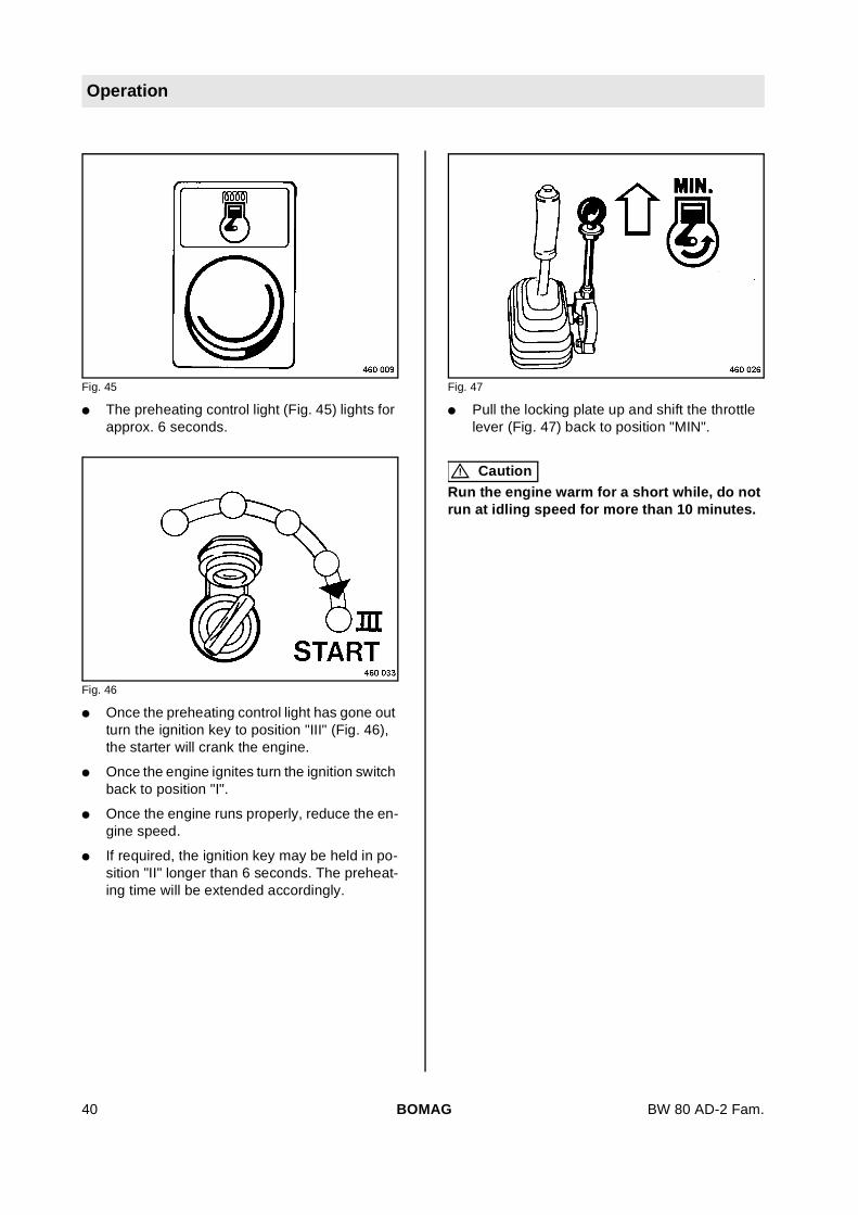
l The preheating control light (Fig. 45) lights forapprox. 6 seconds.
Fig. 46
l Once the preheating control light has gone outturn the ignition key to position "III" (Fig. 46),the starter will crank the engine.
l Once the engine ignites turn the ignition switchback to position "I".
l Once the engine runs properly, reduce the en-gine speed.
l If required, the ignition key may be held in po-sition "II" longer than 6 seconds. The preheat-ing time will be extended accordingly.
Fig. 47
l Pull the locking plate up and shift the throttlelever (Fig. 47) back to position "MIN".
! Caution
Run the engine warm for a short while, do notrun at idling speed for more than 10 minutes.
BOMAG40 BW 80 AD-2 Fam.

Operation
4.5 Starting with jump leads
! Caution
Wrong connection will cause severe damageto the electrical system.
Fig. 48
l When starting with an external battery connectboth plus poles (Fig. 48) first and both minuspoles (earth cable) after.
l Perform all steps as described in the previoussection.
l After starting disconnect the minus poles(earth cable) first and the plus poles after.
4.6 Driving the machine
! Danger
Danger of accident!
Wet and loose soils considerably reduce theground adhesion of the machine on inclina-tions and slopes.
Soil conditions and weather influences impairthe gradability of the machine.
Do not drive up and down inclinations exceed-ing the maximum gradability of the machine(see technical data).
Do not drive without wearing your seat belt.
Always give way to loaded transport vehicles!
Before starting to drive make sure that thedrive range is absolutely safe.
Drive and operate the machine only from thedriver’s seat.
Fig. 49
i Note
Seat contact control light (Fig. 49):
goes out = when the driver’s seat is occu-pied.
lights up whenthe machine is atrest = when the driver’s seat is unoc-
cupied. Drive operation is notpossible. (The brake isclosed).
BOMAG 41BW 80 AD-2 Fam.

Operation
i Note
Standard design
lights when themachine is driv-ing = when the driver’s seat is unoc-
cupied.
i Note
Design with seat contact for engine shut-down*
lights when themachine is driv-ing* = when the driver’s seat is unoc-
cupied. Warning buzzersounds. Engine is shut downafter 8 seconds.
Fig. 50
l Shift the throttle lever (Fig. 50) to position "I" or"II" and lock it.
i Note
During operation the throttle lever always remainsengaged in full load position "I" or "II" .
Control the travel speed only with the travel lever(Fig. 51).
Fig. 51
! Caution
When changing the travel direction hold thetravel lever for a moment in ”0”-position, untilthe machine has stopped, before actuating tothe new travel direction.
l Disengage the travel lever (Fig. 51) to the leftout of braking position and move it slowlythrough ”0”-position to the desired travel direc-tion.
i Note
The parking brake warning light goes out.
Position "I" = max. forward travel without vi-bration
Position "II" = max. backward travel withoutvibration
Position "III" = Max. forward/backward travelwith vibration
i Note
When shifting the travel lever through position "III"to position "I" or "II", the vibration will be automati-cally switched off.
* Optional equipment
BOMAG42 BW 80 AD-2 Fam.

Operation
4.7 Operating the parkingbrake, stopping the ma-chine
Fig. 52
l Shift the travel lever (Fig. 52) slowly to position"0". The hydrostatic drive automatically brakesthe machine.
Fig. 53
l Check, whether the travel lever (Fig. 53) islocked to the right in braking position.
i Note
The travel lever returns automatically to parkingbrake position when releasing it in "0"-position.
The pressure sprinkler system is automaticallyswitched off.
Fig. 54
i Note
The parking brake warning light (Fig. 54) lights up.
BOMAG 43BW 80 AD-2 Fam.

Operation
4.8 Switching the vibration onand off
! Danger
Risk of damage!
When compacting with vibration you mustcheck the effect on nearby buildings and un-derground supply lines (gas, water, sewage,electric power), if necessary stop compactionwork with vibration.
! Caution
Danger of bearing damage!
Do not activate the vibration on hard (frozen,concrete) ground.
i Note
Switch the vibration on only at maximum enginespeed.
Vibration at standstill causes transverse ruts,therefore:
l switch the vibration on only after shifting thetravel lever to the desired travel direction.
l Switch the vibration off before stopping themachine.
Pre-selecting vibration (only AD)
Fig. 55
! Caution
Destruction of hydraulic components!
Switch over only with the vibration switchedoff.
l Pre-select the desired drum or drums with theball valve (Fig. 55).
Position "I" = Vibration of both drums
Position "II" = Vibration of front drum only
Pre-selecting vibration (3 stages, onlyAD)*
Fig. 56
! Caution
Destruction of hydraulic components!
Switch over only with the vibration switchedoff.
l Pre-select the desired drum or drums with theball valve (Fig. 56).
Position up-ward = Vibration of rear drum only
Position horizon-tal = Vibration of both drums
Position down-ward = Vibration of front drum only
* Optional equipment
BOMAG44 BW 80 AD-2 Fam.

Operation
Switch the vibration on
Fig. 57
l Shift the throttle lever (Fig. 57) to position "I"(40 Hz) or "II" (60 Hz) and lock it.
Fig. 58
l Shift the travel lever (Fig. 58) slowly to the de-sired travel direction, max. to position "III".
Fig. 59
l Actuate the vibration push button (Fig. 59).
i Note
When actuating the travel lever (Fig. 58) throughposition "III", vibration will be automaticallyswitched off.
Switching off vibrationl Actuate the vibration push button (Fig. 59)
again.
BOMAG 45BW 80 AD-2 Fam.

Operation
4.9 Switching the gravity sprin-kler system on or off
Fig. 60
l Rotary switch for sprinkler system (Fig. 60).
Position "left" = sprinkling "OFF"
Position "right" = sprinkling "ON"
4.10 Switching the pressuresprinkling system on andoff*
Fig. 61
l Rotary switch for sprinkling system 8 (Fig. 61)
Position left = Sprinkling "OFF"
Position right = Sprinkling "ON"
l Set the interval switch (7) to the desired flowinterval.
Position "A" = Permanent sprinkling
Position "B" to"F" = Interruption intervals of sprin-
kling of 4, 8, 16, 24 and 32 sec-onds, always switched on for 5seconds.
i Note
The pressure sprinkling system is automaticallystopped when the travel lever is in parking brakeposition.
This ensures that the machine will not use any wa-ter when not in operation
In order to test the function of the sprinkling sys-tem with the machine stopped shift the travel leversideways out of braking position.
* Optional equipment
BOMAG46 BW 80 AD-2 Fam.

Operation
4.11 Checking the sprinklingsystem with the machinestopped
Fig. 62
l Shifting the travel lever to the right throughbraking position "0" activates the parkingbrake, the water sprinkling system is automat-ically switched off, checking of sprinkling sys-tem is not possible.
l Shift the travel lever to the left through brakeposition "0" and hold it in position, checkwhether sprinkling system switches on.
4.12 Switching the tire sprinklersystem in or off
i Note
AC-machines only.
Fig. 63
l Operate the foot switch 18 (Fig. 63).
depress = to switch on or off.
BOMAG 47BW 80 AD-2 Fam.
Operation
4.13 Stopping the engine/ma-chine
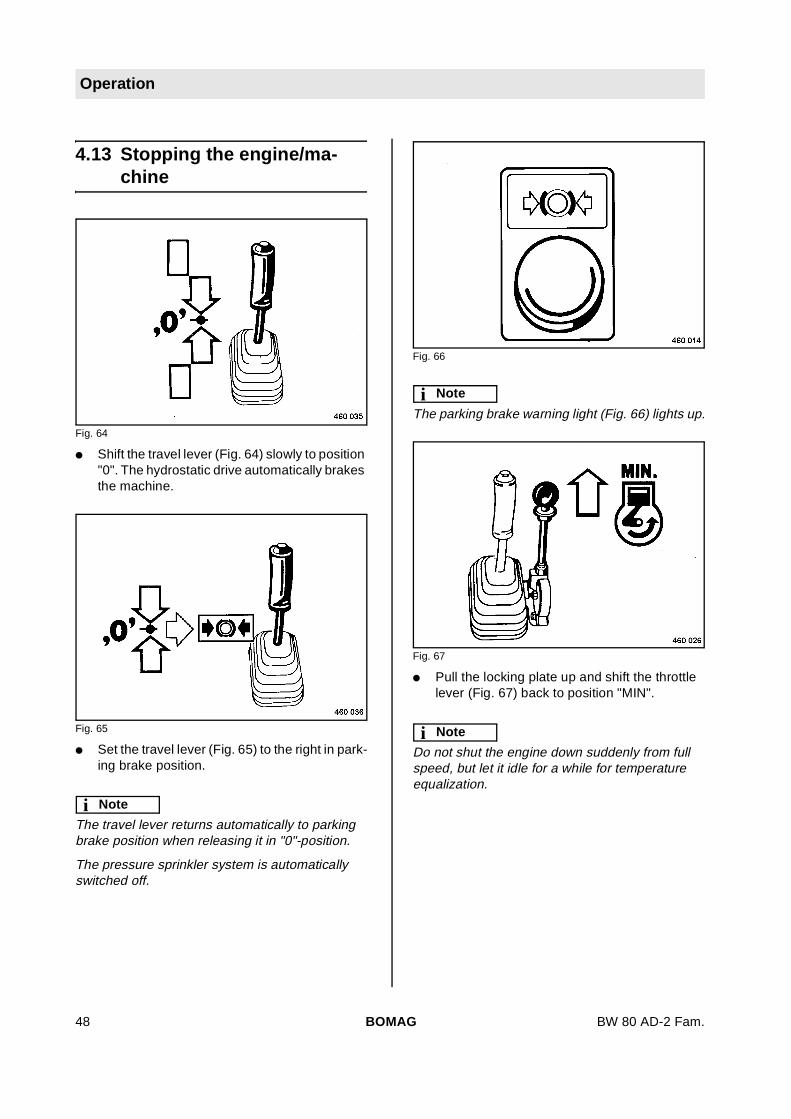
Fig. 64
l Shift the travel lever (Fig. 64) slowly to position"0". The hydrostatic drive automatically brakesthe machine.
Fig. 65
l Set the travel lever (Fig. 65) to the right in park-ing brake position.
i Note
The travel lever returns automatically to parkingbrake position when releasing it in "0"-position.
The pressure sprinkler system is automaticallyswitched off.
Fig. 66
i Note
The parking brake warning light (Fig. 66) lights up.
Fig. 67
l Pull the locking plate up and shift the throttlelever (Fig. 67) back to position "MIN".
i Note
Do not shut the engine down suddenly from fullspeed, but let it idle for a while for temperatureequalization.
BOMAG48 BW 80 AD-2 Fam.
Operation
Fig. 68
l To shut the engine down turn the ignitionswitch (Fig. 68) to position "0".
i Note
After shutting the engine down the parking brakewarning light will light up.
! Danger
Danger of accident!
Secure the machine properly against unau-thorized use, pull the ignition key out.
Always secure parked machines, which couldbe in the way, with appropriate measures.
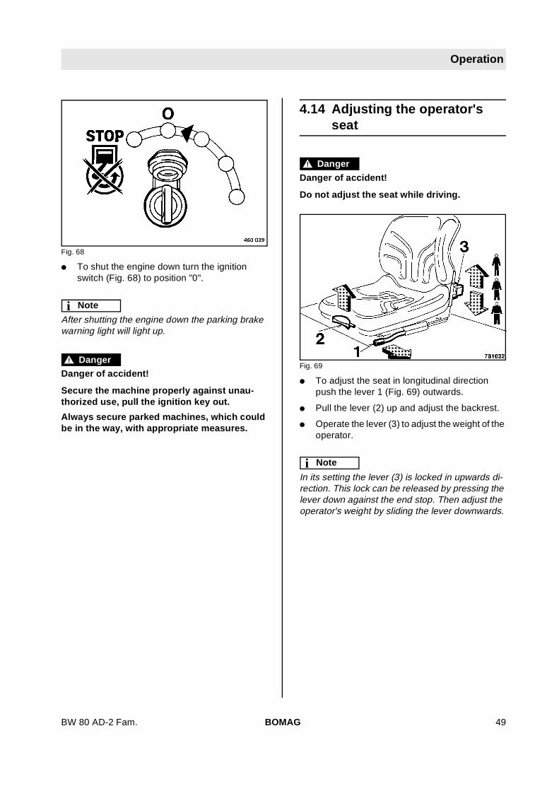
4.14 Adjusting the operator'sseat
! Danger
Danger of accident!
Do not adjust the seat while driving.
Fig. 69
l To adjust the seat in longitudinal directionpush the lever 1 (Fig. 69) outwards.
l Pull the lever (2) up and adjust the backrest.
l Operate the lever (3) to adjust the weight of theoperator.
i Note
In its setting the lever (3) is locked in upwards di-rection. This lock can be released by pressing thelever down against the end stop. Then adjust theoperator's weight by sliding the lever downwards.
BOMAG 49BW 80 AD-2 Fam.
Operation
4.15 Towing*
! Caution
Tow the machine only with the brake releasingdevice attached, otherwise lift by central liftinghook.
! Danger
Danger of accident!
Always secure the machine against unintend-ed rolling.
Release the brake
Fig. 70
l Unscrew the locking bolt (Fig. 70).
l Switch the ball valve over.
Position "I" = Brake released
Position "II" = Brake applied
l Turn the steering wheel anti-clockwise untilthe brake is released.
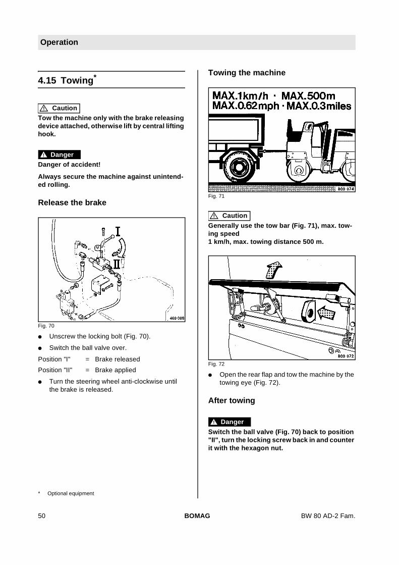
Towing the machine
Fig. 71
! Caution
Generally use the tow bar (Fig. 71), max. tow-ing speed1 km/h, max. towing distance 500 m.
Fig. 72
l Open the rear flap and tow the machine by thetowing eye (Fig. 72).
After towing
! Danger
Switch the ball valve (Fig. 70) back to position"II", turn the locking screw back in and counterit with the hexagon nut.
* Optional equipment
BOMAG50 BW 80 AD-2 Fam.

Operation
4.16 Loading and transport
! Danger
Danger of accident!
Use only strong and stable loading ramps.Make sure that no persons are endangered ifthe machine should turn over or slip off.
Lash the machine down so that it is properlysecured against rolling off, slipping and turn-ing over.
Do not step or stand under loads being lifted.
Always use shackles on the lifting points toload, lift or lash down the machine.
Always check the fastening of the central lift-ing hook before attempting to lift the machine.
Fig. 73
l After driving the machine on the transport ve-hicle swing the articulation lock 1 (Fig. 73) outof its receptacle to the front. Insert the pin (2)and secure it with the cotter pin (3).
Fig. 74
l Lash the machine to the transport vehicle, at-tach the lashing gear (Fig. 74) to the front andrear frames.
l On BW 80 AD/ADH-2 use the fastening hooksto attach the lashing tackle for lashing the ma-chine down.
Fig. 75
l To lift the machine attach the lifting gear to thecentral lifting device (Fig. 75).
BOMAG 51BW 80 AD-2 Fam.
Operation
Loading weight: see technical data.
After the transport
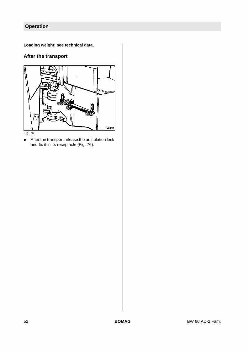
Fig. 76
l After the transport release the articulation lockand fix it in its receptacle (Fig. 76).
BOMAG52 BW 80 AD-2 Fam.

BW 80 AD-2 Fam.
5 Maintenance
BOMAG 53

Maintenance
5.1 General notes on mainte-nance
When servicing the machine pay careful attentionto all applicable safety instructions.
Thorough maintenance of the machine ensuresmaximum reliability and prolongs the lifetime of im-portant components. The effort required for theseactivities is small when being compared with theproblems which may arise, if these instructions arenot observed.
The terms left/right are always related to travel di-rection forward.
l Clean machine and engine thoroughly beforestarting maintenance work.
l For maintenance work park the machine onlevel ground.
l Maintenance work must generally be carriedout with the engine shut down.
l Depressurize hydraulic lines before workingon them.
l Disconnect the battery and cover it with insu-lation material before starting to work on elec-trical components.
l Always attach the articulation lock (transportlock) before starting to work in the articulationarea of the machine.
Environment
Catch running out oils, coolant and fuel and donot let them seep into the ground or into thesewage system. Dispose of oils, coolant andfuels environmentally.
Notes on the fuel systemThe lifetime of the diesel engine is decisively de-pending on the cleanliness of the fuel.
l Keep the engine free of dirt and water as thiscould damage the injection elements of the en-gine.
l Zinc lined drums are not suitable for storing fu-el.
l The fuel drum should rest for a longer periodof time before drawing off fuel.
l Do not let the suction hose disturb the sludgeon the bottom of the drum.
l Do not draw off fuel from near the bottom ofthe fuel drum.
l Fuel left in the fuel drum is not suitable for theengine and should only be used for cleaningpurposes.
Notes on the engine performanceCombustion air and fuel injection rates of the die-sel engine have been carefully adjusted and deter-mine the engine's performance and temperaturelevel as well as the quality of the exhaust gas.
If your machine has to operate permanently in"thin air" (at high altitudes) and with full power, youshould consult the after sales service of BOMAGor the service department of the engine manufac-turer.
Notes on the hydraulic systemWhen servicing the hydraulic system cleanlinessis of utmost importance. Make sure, that no dirt orother contaminating substances enter into the sys-tem. Small particles can flute valves, cause pumpsto seize and block restrictors and pilot bores,thereby causing costly repairs.
l If during the daily oil level check the oil level isfound to have dropped, check all lines, hosesand components for leakages.
l Seal external leakages immediately. If neces-sary inform the after sales service of BOMAG.
l Do not store drums with hydraulic oil outside,or at least store them under a cover. Withchanging weather water can penetratethrough the bunghole.
l Always use the filling and filtering unit(BOMAG part-no. 007 610 01) to fill the hy-draulic system. This unit is fitted with a fine fil-ter, which cleans the hydraulic oil and therebyprolongs the lifetime of the system filter.
l Clean fittings, filler caps and their immediatesurrounding area before removing them, sothat no dirt can fall in.
l Do not leave the tank opening unnecessarilyopen, cover it so that no dirt can fall in.
BOMAG54 BW 80 AD-2 Fam.

Maintenance
Notes on the cooling systemOn water cooled engines the preparation andmonitoring of the coolant is of utmost importance,as otherwise engine failures caused by corrosion,caviation and freezing may occur.
The coolant is a mixture of water and a coolingsystem protection agent.
The cooling system must be continuously moni-tored. Apart from the inspection of the coolant lev-el it means also the inspection of the concentrationof cooling system protection agent.
The concentration of the cooling system protectionagent can be checked with commercially availabletest instruments (glycomat).
! Danger
Health hazard!
The mixing of nitride based cooling systemprotection agents with amine based agents willcause the generation of highly toxic nitro-samines.
Environment
Cooling system protection agents must be dis-posed of environmentally.
5.2 Fuels and lubricants
Engine oilIn order to assure perfect cold starting it is importto chose the viscosity (SAE-class) of the engine oilaccording to the ambient temperature.
Fig. 77
Lubrication oil with a too high viscosity index caus-es starting difficulties. The temperature whenstarting the engine is therefore of highest impor-tance when choosing the viscosity of engine oil forwinter operation.
Oil viscositySince lubrication oil changes its viscosity with thetemperature, the ambient temperature at the oper-ating location of the engine is of utmost impor-tance when choosing the viscosity class (SAE-class) (see diagram).
Occasional falling short of the temperature limit(e.g. use of SAE 15W/40 down to -15°C) may ef-fect the cold starting ability of the engine, but willnot cause any engine damage.
Temperature related lubrication oil changes canbe avoided by using multi-purpose oils. The follow-ing oil change intervals apply also when using mul-ti-purpose oils.
Regular lubrication oil changesThe longest permissible time a lubrication oilshould remain in an engine is 1 year. If the follow-ing oil change intervals are not reached over a pe-riod of 1 year, the oil change should be performed
BOMAG 55BW 80 AD-2 Fam.

Maintenance
at least once per year, irrespective of the operatinghours reached.
Oil qualityLubrication oil are classified according to their per-formance and quality class. Specifications accord-ing to API (American Petroleum Institute) andCCMC (Committee of Common Market Automo-bile Constructors) are commonly used.
Permitted API-oils
Aspiratingengines = CD/SE
Permitted CCMC-oils
Aspiratingengines = D4
Lubrication oil change intervals
! Caution
These intervals apply only when using a dieselfuel with maximum 0.5 % sulphur by weightand for ambient temperatures higher than-10 °C.
CCMC-D4 = 250 operating hours
API: CD/SE = 250 operating hours
When using fuels with a sulphur content of morethan 0,5% to 1% or under ambient temperaturesbelow -10°C the oil change intervals must behalved.
For fuels with a sulphur content of more than 1%you should consult the responsible service agen-cy.
Fuels
Quality
You should only use commercially available branddiesel fuel with a sulphur content below 0.5% andensure strict cleanliness when filling in. A highersulphur content has a negative effect on the oilchange intervals. Use only winter-grade diesel fuelunder low ambient temperatures. The fuel levelshould always be topped up in due time so that thefuel tank is never run dry, as otherwise filter and in-jection lines need to be bled.
The following fuel specifications are permitted:DIN/EN 590; DIN 51 601; Nato Codes: F-54, F-75;BS 2869: A1 and A2; ASTM D 975-78: 1-D and 2-D.
Winter fuelFor winter operation use only winter diesel fuel, toavoid clogging because of paraffin separation. Atvery low temperatures disturbing paraffin separa-tion can also be expected when using winter dieselfuel.
In most cases a sufficient cold resistance can alsobe achieved by adding flow enhancing fuel addi-tives. Consult the engine manufacturer.
Hydraulic oilThe hydraulic system is operated with hydraulic oilHV 32 (ISO) with a kinematic viscosity of32 mm2/s at 40°C. For topping up or for oil chang-es use only high-quality hydraulic oil, type HVLPaccording to DIN 51524, part 3, or hydraulic oilstype HV according to ISO 6743/3. The viscosity in-dex (VI) should be at least 150 (observe informa-tion of manufacturer).
Bio-degradable hydraulic oilOn request the hydraulic system can also be filledwith synthetic ester based biodegradable hydrau-lic oil (Panolin HLP Synth. 32). The biologicallyquickly degradable hydraulic oil meets all de-mands of a mineral oil based hydraulic oil accord-ing to DIN 51524.
In hydraulic systems filled with Panolin HLP Synth.32 always use the same oil to top up. Whenchanging from mineral oil based hydraulic oil to anester based biologically degradable oil, you shouldconsult the lubrication oil service of the oil manu-facturer for details.
Check the filter more frequently after this change.
Lubrication greaseFor lubrication use only EP-high pressure grease,lithium saponified (penetration 2).
CoolantFor coolant mixtures use only soft tap water (drink-ing water) with a water hardness between 3 and12 °dGH. The water should not contain more than
BOMAG56 BW 80 AD-2 Fam.

Maintenance
100 mg/dm3 of chlorine and sulphate. The ph-val-ue should be between 6.5 and 8.5.
As a protection against frost, corrosion and boilingpoint anti-freeze agents must be used under anyclimatic conditions.
The proportion of cooling system protection agentmust be between min. 35% and max. 45% to thewater.
! Caution
Do not mix different coolants and additives ofany other kind.
BOMAG 57BW 80 AD-2 Fam.

Maintenance
5.3 Table of fuels and lubri-cants
Assembly Fuel or lubricant Quantity approx.
Summer Winter Attention
Observe the level marks
Engine Engine oil API: CD/SE or CD/SF SHPD CCMC-D4-D5-PD1
3,9 lup to max. dipstick mark
SAE 10W/40 (-20 °C to +30 °C)
SAE 15W/40
(-10°C to + 40°C)
SAE 30 SAE 10W
(+5 °C to +30 °C) (-5 °C to -30 °C)
SAE 40 SAE 20W/20
(+25°C to +40°C) (+10°C to -10°C)
Fuel
Diesel Winter diesel fuel (downto -12 °C)
23 litres
Cooling system Coolant
Water + anti-freeze 1,9 l
Hydraulic system Hydraulic oil (ISO), HV32, kinem. viscosity32 mm2/s at 40 °C
up to middle of dipstickapprox. 9 litres (tank ca-pacity)
or biodegradable hydraulic oil,ester based
Sprinkler system Water Anti-freeze mixture as required
Water* 100 litres
Sprinkling of tires Emulsion 10 litres
Oscillating articulated joint High pressure grease (lithium saponified) as required
**Mix water and anti-freeze agent by following the instructions of the manufacturer
BOMAG58 BW 80 AD-2 Fam.
Maintenance
5.4 Running-in instructions
i Note
The maintenance plan under the engine hoodhelps with the maintenance work!
Maintenance after 50 operating hours
With new or totally overhauled engines you shouldgenerally:
l Change the engine oil.
l Change the engine oil filter.
l Check the engine for leaks
l Tighten the fastening screws on air filter, ex-haust manifold, and other attachments.
! Caution
Retighten the cylinder head fastening screwsto the engine.
Maintenance after 200 operating hours
l New engines normally have a higher oil con-sumption. It is recommended to check the oillevel twice every day during the running-in pe-riod.
l After the running-in period it is quite sufficientto check the oil level once every day.
l Check and retighten the screws on the ma-chine.
l Watch out for leaks.
BOMAG 59BW 80 AD-2 Fam.

Maintenance
5.5 Maintenance chart
With all maintenance intervals perform alsothe work for shorter preceding service inter-vals.
No. Designation Note
Every 10 operating hours
5.6 Check the engine oil level5.7 Check the fuel level5.8 Check the hydraulic oil level up to middle of dipstick marking5.9 Checking the hydraulic oil filter element contamination indicator5.10 Check the coolant level5.11 Check the water level in the sprinkling system Summer: Water Winter: Anti-freeze mixture5.12 Checking the emulsion level AC-machines)5.13 Check, adjust the scrapers
Every 50 operating hours
5.14 Grease the articulated joint High pressure grease5.15 Check the tire pressure (AC-machines)5.16 Check, clean dry air filter, replace if necessary.
Every 250 operating hours
5.17 Changing the engine oil (at least 1x per year)* up to upper dipstick mark5.18 Changing the engine oil filter5.19 Check condition and tension of the V-belt, replace if
necessary.5.20 Check condition and tension of pump drive toothed
belt5.21 Change the fuel pre-cleaner, bleed the fuel system5.22 Clean the cooling fins on radiator and hydraulic oil
cooler5.23 Clean the sprinkler system
Every 500 operating hours
5.24 Changing the main fuel filter5.25 Fuel tank, draining the sludge off5.26 Service the battery
Every 1000 operating hours
5.27 Check and adjust the valve clearance
BOMAG60 BW 80 AD-2 Fam.
Maintenance
Every 2000 operating hours
5.28 Change the hydraulic oil** (at least every 2 years) HV 325.29 Change the hydraulic oil filter** (at least every 2
years)5.30 Change the coolant5.31 Replace the pump drive toothed belt
As required
5.32 Change the dry air filter cartridge (at least 1 x peryear)
5.33 Water sprinkler system, maintenance in case of frost5.34 Tightening torques for screws with metric unified
thread5.35 Engine conservation* When using diesel fuel with a sulphur content of more than 0,5 % by weight the engine oil change intervals must be halved. This
applies also when using engine oil of API-class CC/SE or CC/SF. Example: Fuel 1 % sulphur and lubrication oil CD/SE.** Also in case of repairs in the hydraulic system.
No. Designation Note
BOMAG 61BW 80 AD-2 Fam.

Every 10 operating hours
Every 10 operating hours
5.6 Checking the engine oil lev-el
i Note
Park the machine on level ground, so that the en-gine is in horizontal position.
Fig. 78
l Shut the engine down.
l Pull the oil dipstick (Fig. 78) out, wipe it cleanwith a lint-free cloth and reinsert it until it bot-toms.
l Pull the oil dipstick out again.
l The oil level must reach the top mark on thedipstick.
l Top up oil immediately if the oil level is too low.
For quality and quantity of oil refer to the sec-tion about fuels, lubricants and filling capaci-ties.
l Check the oil level again after a running timeof approx. 1 minute with the engine shut down.
5.7 Checking the fuel level
! Danger
Fire hazard!
Do not inhale any fuel fumes.
When working on the fuel system do not useopen fire, do not smoke.
Do not refuel in closed rooms
! Caution
Dirty fuel can cause engine failures or evendamage to the engine.
If necessary fill in fuel through a strainer orwith a filling gun.
Fig. 79
l Check the fuel level on the fuel gauge (Fig.79).
i Note
Never drive the fuel tank empty, because thiswould required bleeding of the entire fuel system.
l Clean the area around the filler opening.
l Unscrew the filler cap.
l If necessary top up fuel (diesel or winter die-sel).
For quality of fuel refer to the table of fuels andlubricants.
BOMAG62 BW 80 AD-2 Fam.

Every 10 operating hours
5.8 Check the hydraulic oil level
Fig. 80
l Clean the area around the filler opening.
l Remove the filler cap.
l Check the oil level in the inspection glass. Theoil level must be between the "MIN" and "MAX"marks (Fig. 80).
l If the oil level is too low top up hydraulic oil im-mediately.
For quality and quantity of oil refer to the ”ta-ble of fuels, lubricants and filling capacities”.
i Note
If, during the daily inspection of the oil level the hy-draulic oil level is found to have dropped, check alllines, hoses and components for leaks.
In hydraulic systems filled with Panolin HLP Synth.32 always use the same oil to top up. With otherester based oils consult the lubrication oil serviceof the respective oil manufacturer.
5.9 Checking the hydraulic oilfilter element
Fig. 81
l Check the hydraulic oil filter contamination in-dicator at operating temperature and at maxi-mum engine speed.
l If the optical display (Fig. 81) shows red re-place the hydraulic oil filter element immedi-ately.
i Note
After replacing the dirty filter the optical display willshow green.
BOMAG 63BW 80 AD-2 Fam.

Every 10 operating hours
5.10 Checking the coolant level
! Caution
Fill up coolant only when the engine is cold.
Fig. 82
l Check the coolant level (Fig. 82).
! Caution
If, during the daily inspection the coolant levelis found to have dropped, check all lines, hos-es and engine for leaks.
l To top up unscrew the filler cap and fill in cool-ant up to the MAX-mark.
For quality of coolant refer to the chapter 5.2,fuels and lubricants.
5.11 Checking the water level
Fig. 83
l Open the lid (Fig. 83) and check the water lev-el.
l If necessary top up water and close the lid.
i Note
In the event of frost observe the special mainte-nance notes 'water sprinkler system, maintenancein the event of frost'.
Make sure that the bores in the lid are free.
BOMAG64 BW 80 AD-2 Fam.

Every 10 operating hours
5.12 Checking the emulsion level(BW 90 AC-2)
i Note
The mixing ratio of water and emulsion must be inaccordance with the instructions of the manufac-turer.
Fig. 84
l Check the emulsion level in the emulsion tankat the back of the machine, top up if necessary(Fig. 84).
5.13 Cleaning the scrapers
Fig. 85
l Fold the scrapers up and clean them (Fig. 85).This is of particular importance before com-pacting asphalt surfaces.
BOMAG 65BW 80 AD-2 Fam.

Every 50 operating hours
Every 50 operating hours
5.14 Greasing the articulatedjoint
Fig. 86
l Clean the grease nipples (Fig. 86) and lubri-cate with approx. 5 strokes from the greasegun.
For quality of oil refer to the section about fu-els, lubricants and filling capacities.
5.15 Checking the tire pressure
i Note
AC-machines only
Fig. 87
l Check the tire pressure with a pressure gaugeon the tire inflation valve (Fig. 87).
i Note
Ensure even pressure in all tires.
Specified value 2 ... 2,5 bar (29 ... 36 psi)
BOMAG66 BW 80 AD-2 Fam.

Every 50 operating hours
5.16 Checking, cleaning, chang-ing the dry air filter cartridge
! Caution
Excessive exhaust smoke may be caused by asoiled dry air filter cartridge.
A dry air filter cartridge with damaged filter el-ement or seal must be replaced in any case. Itis therefore recommended to keep at least onecartridge in stock.
The dry air filter cartridge must be changed af-ter being cleaned 6 times, but at the latest after1 year.
Each cleaning must be marked with a cross onthe filter cartridge.
In case of a sooty deposit on the cartridgecleaning does not make sense. Use a new filtercartridge.
Incorrectly handled filter elements may be inef-fective because of faults (e.g. cracks) andcause engine damage.
Always replace the filter cartridge if it is soiledwith wet or oily dirt.
Do not use gasoline or any hot fluids to cleanthe filter cartridge.
Fig. 88
l Unscrew the wing screw and take the air filtercartridge (Fig. 88) out of the air filter housing.
Fig. 89
l Clean the air filter housing out with a cloth (Fig.89).
! Caution
Do not blow the air filter housing out with com-pressed air.
Fig. 90
! Danger
Eye injury!
Wear goggles.
l Blow the dry air filter (Fig. 90) out with cleanand dry compressed air with a pressure ofmax. 7 bar.
! Caution
Do not hold the pressure air nozzle closer than3 cm to the filter.
l Always blow along the inner folds.
BOMAG 67BW 80 AD-2 Fam.

Every 50 operating hours
Wet cleaning:
l Clean the filter cartridge by moving it to and froin luke-warm water containing a commercialdetergent. Then rinse it thoroughly in clear wa-ter, shake all water off and let it dry properly.
! Caution
Do not use gasoline or any hot fluids to cleanthe filter cartridge.
Fig. 91
l Use a torch to examine the dry air filter (Fig.91) from inside for any holes, cracks, groovesand damage.
l Replace a damaged dry air filter immediately.
Fig. 92
l Before inserting the cartridge check the seal-ing faces on the dry air filter.
l Insert the dry air filter and fasten it with thewing screw.
! Caution
If the wing screw is not properly tightened dustand dirt may be drawn in. This may damage theengine.
BOMAG68 BW 80 AD-2 Fam.
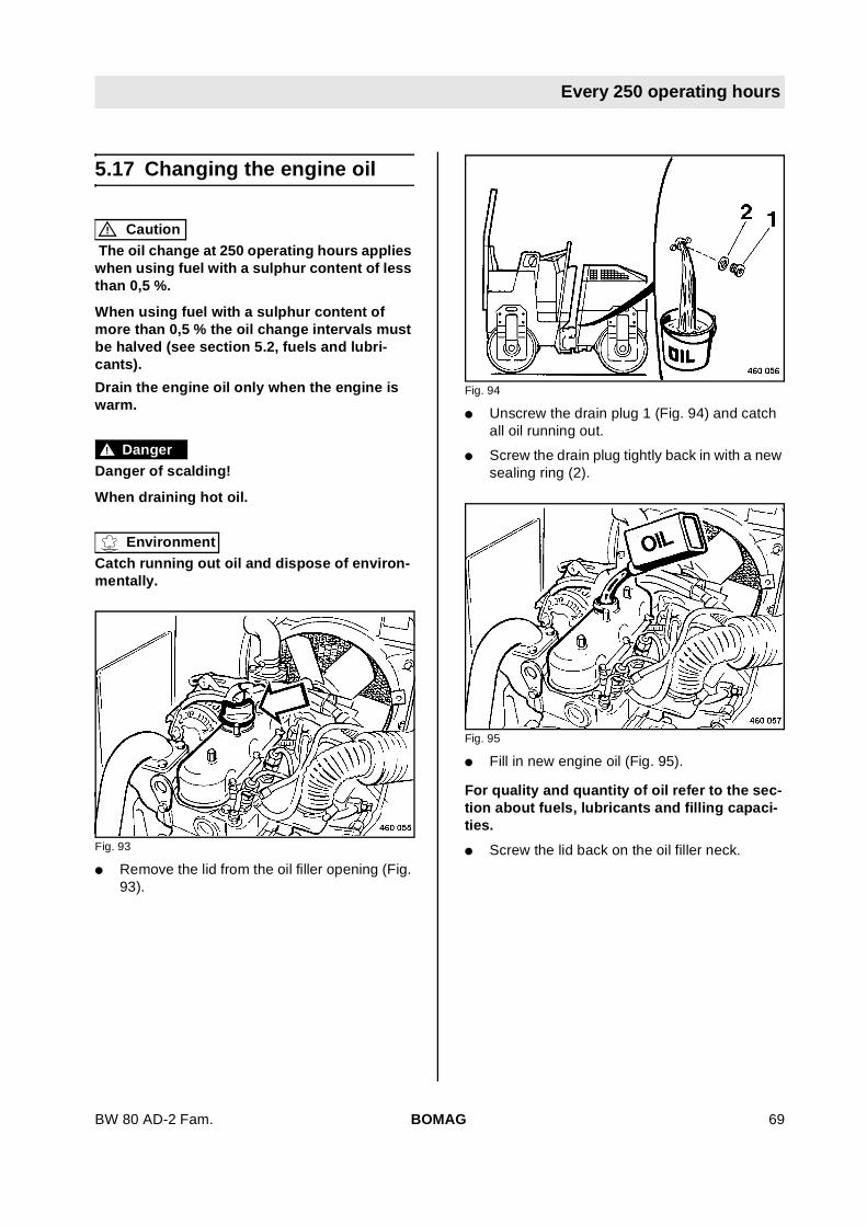
Every 250 operating hours
Every 250 operating hours
5.17 Changing the engine oil
! Caution
The oil change at 250 operating hours applieswhen using fuel with a sulphur content of lessthan 0,5 %.
When using fuel with a sulphur content ofmore than 0,5 % the oil change intervals mustbe halved (see section 5.2, fuels and lubri-cants).
Drain the engine oil only when the engine iswarm.
! Danger
Danger of scalding!
When draining hot oil.
Environment
Catch running out oil and dispose of environ-mentally.
Fig. 93
l Remove the lid from the oil filler opening (Fig.93).
Fig. 94
l Unscrew the drain plug 1 (Fig. 94) and catchall oil running out.
l Screw the drain plug tightly back in with a newsealing ring (2).
Fig. 95
l Fill in new engine oil (Fig. 95).
For quality and quantity of oil refer to the sec-tion about fuels, lubricants and filling capaci-ties.
l Screw the lid back on the oil filler neck.
BOMAG 69BW 80 AD-2 Fam.

Every 250 operating hours
Fig. 96
l After a short test run check the oil level on thedipstick (Fig. 96). The oil level must reach thetop mark on the dipstick, if necessary top upoil.
5.18 Change the engine oil filter
! Danger
Danger of scalding!
There is a danger of scalding by hot oil whenunscrewing the engine oil filter.
Environment
Environmental hazard
Catch running out oil and dispose of environ-mentally together with the engine oil filter car-tridge.
Fig. 97
l Unscrew the filter cartridge (Fig. 97) with asuitable filter wrench.
l Wipe the sealing face on the engine clean.
l Apply some clean oil to the rubber seal on thenew filter cartridge.
l Screw the new filter cartridge on and tighten ithand tight.
l After a short test run examine the engine forleaks and check the oil level, if necessary topup oil.
BOMAG70 BW 80 AD-2 Fam.

Every 250 operating hours
5.19 Checking the condition, ten-sion of the V-belt, changingthe V-belt
! Danger
Danger of accident!
This work must only be performed with the en-gine shut down.
Checking the V-belt
Fig. 98
l Examine the entire circumference of the V-belt(Fig. 98) for damage and cracks. Replacedamaged or cracked V-belts.
l Apply thumb pressure to check whether the V-belt can be depressed for more than 7 to 9 mmbetween the V-belt pulleys, if necessary reten-sion.
Tensioning the V-belt
Fig. 99
l Slacken the fastening screws 1 and 2 (Fig.99).
l Press the generator towards the outside untilthe correct tension of the V-belt is reached.
l Tighten all fastening screws and check the V-belt tension again.
Changing the V-belt
i Note
Remove the guard from the blower.
Fig. 100
l Slacken the fastening screws 1 and 2 (Fig.100).
l Push the generator completely towards theengine..
l Take the old V-belt off.
BOMAG 71BW 80 AD-2 Fam.

Every 250 operating hours
l Place the new V-belt on the V-belt pulleys.
l Tension the V-belt as described before.
! Danger
Danger of injury!
Reassemble the guard for the blower.
! Caution
Check the V-belt tension after a running time of30 minutes.
5.20 Checking the condition andtension of the toothed beltfor the pump drive
! Danger
Danger of accident!
This work must only be performed with the en-gine shut down!
Fig. 101
l Remove the protection hood (Fig. 101).
Fig. 102
l Check the entire circumference of the toothedbelt (Fig. 102) for starting cracks in the area ofthe basis and the back of the teeth.
l Have the toothed belt replaced if startingcracks are found.
l Use the belt tension tester (BOMAG P/N079 947 10) to check whether the toothed beltcan be depressed 6 to 8 mm between the
BOMAG72 BW 80 AD-2 Fam.

Every 250 operating hours
toothed belt pulleys when applying a pressingforce of 70 N.
l Required frequency 100-130 Hz.
l Reassemble the protection hood.
5.21 Changing the fuel preclean-er, bleeding the fuel system
! Danger
Fire hazard!
When working on the fuel system do not useopen fire, do not smoke.
Do not spill any fuel.
! Caution
Environmental hazard!
Catch running out fuel, do not let it seep intothe ground.
Fig. 103
l Loosen the hose clamp (Fig. 103).
l Pull the fuel filter out of the bottom and the tophoses.
l Install a new fuel filter by observing the flow di-rection.
Bleeding the fuel system
! Danger
Fire hazard!
Do not bleed the fuel system while the engineis hot. Fuel may drip onto the hot exhaust.
l In the following cases the fuel system needs tobe bled: after changing the fuel filter, after run-ning the fuel tank dry, after a long resting peri-od of the machine.
BOMAG 73BW 80 AD-2 Fam.
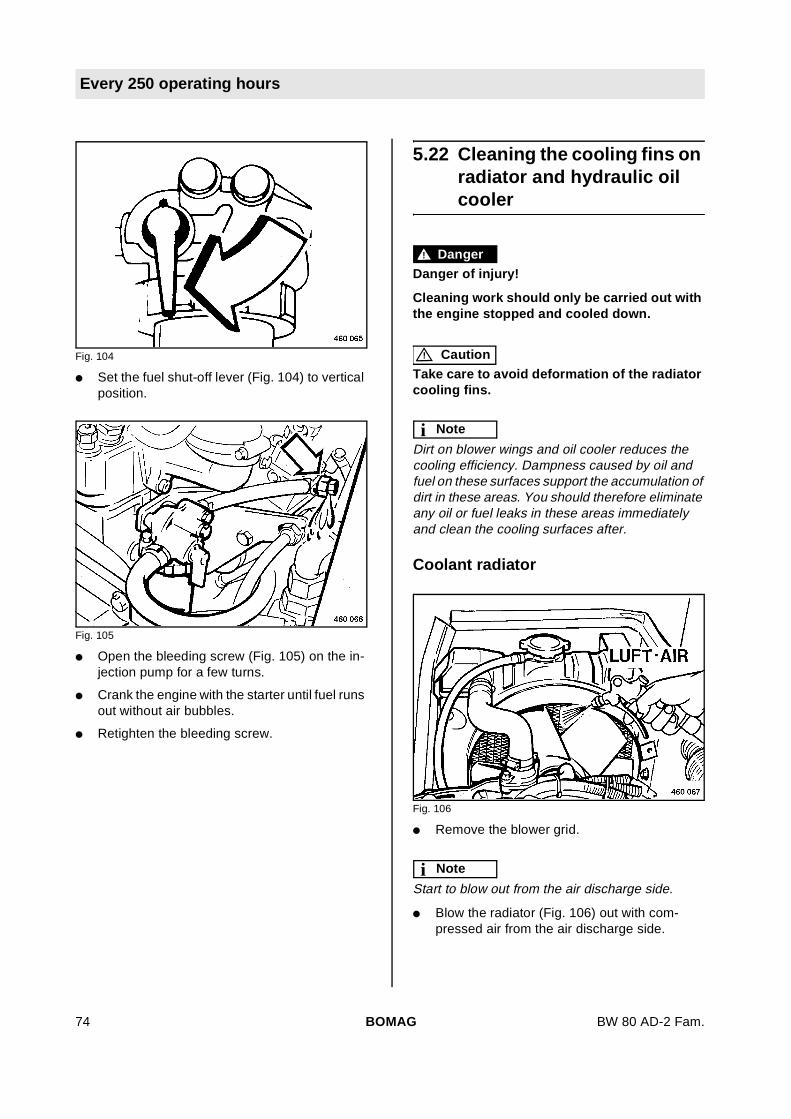
Every 250 operating hours
Fig. 104
l Set the fuel shut-off lever (Fig. 104) to verticalposition.
Fig. 105
l Open the bleeding screw (Fig. 105) on the in-jection pump for a few turns.
l Crank the engine with the starter until fuel runsout without air bubbles.
l Retighten the bleeding screw.
5.22 Cleaning the cooling fins onradiator and hydraulic oilcooler
! Danger
Danger of injury!
Cleaning work should only be carried out withthe engine stopped and cooled down.
! Caution
Take care to avoid deformation of the radiatorcooling fins.
i Note
Dirt on blower wings and oil cooler reduces thecooling efficiency. Dampness caused by oil andfuel on these surfaces support the accumulation ofdirt in these areas. You should therefore eliminateany oil or fuel leaks in these areas immediatelyand clean the cooling surfaces after.
Coolant radiator
Fig. 106
l Remove the blower grid.
i Note
Start to blow out from the air discharge side.
l Blow the radiator (Fig. 106) out with com-pressed air from the air discharge side.
BOMAG74 BW 80 AD-2 Fam.

Every 250 operating hours
Fig. 107
l Blow the coolant radiator (Fig. 107) out fromthe air intake side.
Hydraulic oil cooler
Fig. 108
l Blow the hydraulic oil cooler (Fig. 108) outfrom the air discharge side first.
Fig. 109
l Blow the hydraulic oil cooler (Fig. 109) outfrom the air intake side.
Cleaning with cold cleansing agent
! Caution
Protect electrical equipment such as genera-tor, regulator and starter against the direct wa-ter jet.
l Spray the engine with a suitable cleansingagent, e.g. cold cleansing agent and wash itoff with a strong water jet after a sufficientsoaking time.
l Run the engine warm for a short time to avoidcorrosion.
l Reassemble the blower grid.
BOMAG 75BW 80 AD-2 Fam.

Every 250 operating hours
5.23 Cleaning the water sprinklersystem
i Note
In the event of frost observe the special mainte-nance notes 'water sprinkler system, maintenancein the event of frost'.
l Drain the water tank.
Fig. 110
l Open the rear flap 1 (Fig. 110).
l Unscrew the spigot nut (2).
l Unscrew the water filter (3) and clean it.
l Flush the water tank thoroughly.
l Screw the water filter back in, tighten the spig-ot nut and close the flap.
Fig. 111
l Pull the caps 3 (Fig. 111) off both sprinklertubes.
l Loosen the hose clamps (2) and pull the hosesof the sprinkler tubes.
l Pull the sprinkler tubes (3) out and flush themthoroughly.
l Assemble the sprinkler tubes and fill the watertank.
Environment
Dispose of emulsion fluid environmentally.
l Drain the emulsion tank.
Fig. 112
l Unscrew the fitting.
l Take the emulsion filter (Fig. 112) out andclean it.
l Thoroughly rinse the emulsion tank.
l Reinsert the emulsion filter.
l Turn the fitting back on.
BOMAG76 BW 80 AD-2 Fam.
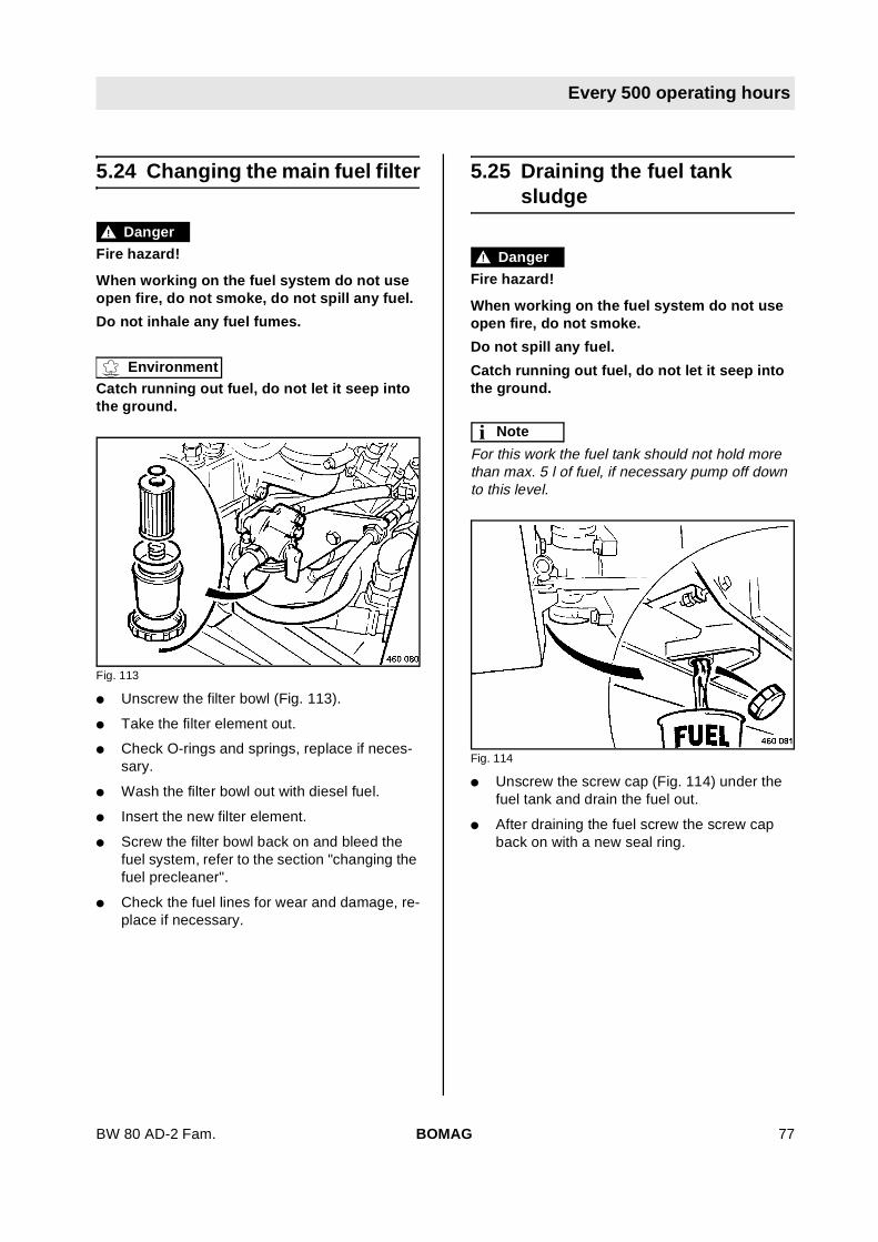
Every 500 operating hours
Every 500 operating hours
5.24 Changing the main fuel filter
! Danger
Fire hazard!
When working on the fuel system do not useopen fire, do not smoke, do not spill any fuel.
Do not inhale any fuel fumes.
Environment
Catch running out fuel, do not let it seep intothe ground.
Fig. 113
l Unscrew the filter bowl (Fig. 113).
l Take the filter element out.
l Check O-rings and springs, replace if neces-sary.
l Wash the filter bowl out with diesel fuel.
l Insert the new filter element.
l Screw the filter bowl back on and bleed thefuel system, refer to the section "changing thefuel precleaner".
l Check the fuel lines for wear and damage, re-place if necessary.
5.25 Draining the fuel tanksludge
! Danger
Fire hazard!
When working on the fuel system do not useopen fire, do not smoke.
Do not spill any fuel.
Catch running out fuel, do not let it seep intothe ground.
i Note
For this work the fuel tank should not hold morethan max. 5 l of fuel, if necessary pump off downto this level.
Fig. 114
l Unscrew the screw cap (Fig. 114) under thefuel tank and drain the fuel out.
l After draining the fuel screw the screw capback on with a new seal ring.
BOMAG 77BW 80 AD-2 Fam.
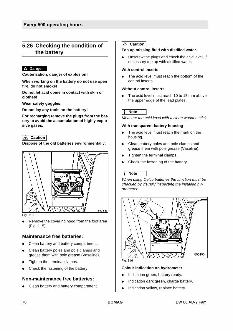
Every 500 operating hours
5.26 Checking the condition ofthe battery
! Danger
Cauterization, danger of explosion!
When working on the battery do not use openfire, do not smoke!
Do not let acid come in contact with skin orclothes!
Wear safety goggles!
Do not lay any tools on the battery!
For recharging remove the plugs from the bat-tery to avoid the accumulation of highly explo-sive gases.
! Caution
Dispose of the old batteries environmentally.
Fig. 115
l Remove the covering hood from the foot area(Fig. 115).
Maintenance free batteries:l Clean battery and battery compartment.
l Clean battery poles and pole clamps andgrease them with pole grease (Vaseline).
l Tighten the terminal clamps.
l Check the fastening of the battery.
Non-maintenance free batteries:l Clean battery and battery compartment.
! Caution
Top up missing fluid with distilled water.
l Unscrew the plugs and check the acid level, ifnecessary top up with distilled water.
With control inserts
l The acid level must reach the bottom of thecontrol inserts.
Without control inserts
l The acid level must reach 10 to 15 mm abovethe upper edge of the lead plates.
i Note
Measure the acid level with a clean wooden stick.
With transparent battery housing
l The acid level must reach the mark on thehousing.
l Clean battery poles and pole clamps andgrease them with pole grease (Vaseline).
l Tighten the terminal clamps.
l Check the fastening of the battery.
i Note
When using Delco batteries the function must bechecked by visually inspecting the installed hy-drometer.
Fig. 116
Colour indication on hydrometer.
l Indication green, battery ready.
l Indication dark green, charge battery.
l Indication yellow, replace battery.
BOMAG78 BW 80 AD-2 Fam.

Every 500 operating hours
BOMAG 79BW 80 AD-2 Fam.

Every 1000 operating hours
Every 1000 operating hours
5.27 Checking, adjusting thevalve clearance
i Note
The valve clearance must only be checked andadjusted when the engine is cold.
! Caution
The first cylinder is at the front on the blowerend.
Fig. 117
l Remove the cylinder head cover (Fig. 117).
Fig. 118
l Remove the protection hood (Fig. 118).
Fig. 119
l Align the mark "1TC" 2 (Fig. 119) on the fly-wheel to the mark (1) on the housing.
i Note
the piston of cylinder 1 is in top dead center. The"1TC"-mark is only valid for cylinder 1.
Fig. 120
l Check whether the piston of cylinder 1 is incompression position or in overlap position, todo so turn the flywheel 15° to right or left re-spectively.
Overlapping = both valves are moving andcannot be checked or adjust-ed.
Compression po-sition = none of the valves moves and
can be checked or adjusted.
i Note
I = Inlet valve
BOMAG80 BW 80 AD-2 Fam.

Every 1000 operating hours
E = Exhaust valve
l Check the valves marked black (Fig. 120) oncylinders 1, 2 and 3, adjust if necessary.
Fig. 121
l Check the gap between rocker arm and valvewith a feeler gauge (Fig. 121).
Valve clearance:
Inlet valve and exhaust valve 0,145 - 0,185 mm.
l If the gap is too narrow or too wide for the feel-er gauge the valve clearance must be adjust-ed.
i Note
Mark checked and adjusted valves with chalk.
Fig. 122
l Turn the flywheel for another 360° and alignthe "1TC"-mark with the mark on the mark onthe housing.
l Check the valves marked black on cylinders 2and 3 (Fig. 122), adjust if necessary.
l Install the cylinder head cover with a new gas-ket.
i Note
After a short test run check the engine for leaks.
BOMAG 81BW 80 AD-2 Fam.
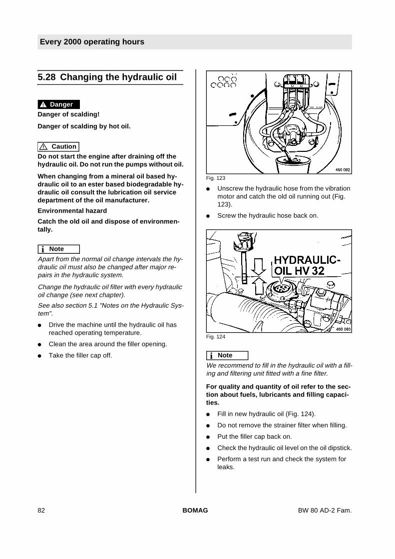
Every 2000 operating hours
Every 2000 operating hours
5.28 Changing the hydraulic oil
! Danger
Danger of scalding!
Danger of scalding by hot oil.
! Caution
Do not start the engine after draining off thehydraulic oil. Do not run the pumps without oil.
When changing from a mineral oil based hy-draulic oil to an ester based biodegradable hy-draulic oil consult the lubrication oil servicedepartment of the oil manufacturer.
Environmental hazard
Catch the old oil and dispose of environmen-tally.
i Note
Apart from the normal oil change intervals the hy-draulic oil must also be changed after major re-pairs in the hydraulic system.
Change the hydraulic oil filter with every hydraulicoil change (see next chapter).
See also section 5.1 "Notes on the Hydraulic Sys-tem".
l Drive the machine until the hydraulic oil hasreached operating temperature.
l Clean the area around the filler opening.
l Take the filler cap off.
Fig. 123
l Unscrew the hydraulic hose from the vibrationmotor and catch the old oil running out (Fig.123).
l Screw the hydraulic hose back on.
Fig. 124
i Note
We recommend to fill in the hydraulic oil with a fill-ing and filtering unit fitted with a fine filter.
For quality and quantity of oil refer to the sec-tion about fuels, lubricants and filling capaci-ties.
l Fill in new hydraulic oil (Fig. 124).
l Do not remove the strainer filter when filling.
l Put the filler cap back on.
l Check the hydraulic oil level on the oil dipstick.
l Perform a test run and check the system forleaks.
BOMAG82 BW 80 AD-2 Fam.

Every 2000 operating hours
Bleeding the hydraulic systeml Run the engine for max. 3 minutes at idle
speed, this will bleed the hydraulic system.
5.29 Changing the hydraulic oilfilter element
! Danger
Danger of scalding!
Danger of scalding by hot hydraulic oil.
! Caution
Do not reuse the oil in the filter bowl.
Environmental hazard!
Catch running out oil and dispose of environ-mentally.
i Note
If the hydraulic oil contamination indicator on thefilter shows 'red' while the engine is running andthe machine has operating temperature, changethe filter element.
When the oil filter element is clean the hydraulic oilfilter contamination indicator shows 'green'.
The filter element must be changed with every hy-draulic oil change and after major repairs in the hy-draulic system.
If the filter has to be changed together with the hy-draulic oil, the filter should in any case be changedafter the oil change and the test run.
Fig. 125
l Unscrew the filter bowl (Fig. 125) from the filterhousing.
l Take the old filter element out and dispose ofenvironmentally.
BOMAG 83BW 80 AD-2 Fam.

Every 2000 operating hours
l Clean the filter bowl.
l Insert the filter element with the opening facingupwards and screw the filter bowl on, observethe condition of the seal ring.
5.30 Changing the coolant
! Danger
Danger of scalding!
Change the coolant only when the engine iscold.
Environment
Catch running out coolant and dispose of envi-ronmentally.
Fig. 126
l Remove the radiator cap (Fig. 126).
Fig. 127
l Unscrew the drain cock (Fig. 127).
l Drain the coolant completely off and collect it.
l Screw the drain cock back in.
l Empty the coolant compensation tank.
BOMAG84 BW 80 AD-2 Fam.
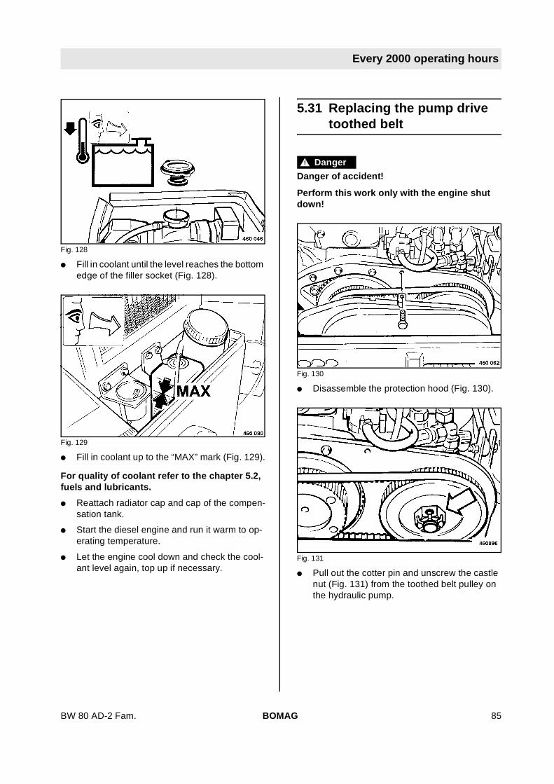
Every 2000 operating hours
Fig. 128
l Fill in coolant until the level reaches the bottomedge of the filler socket (Fig. 128).
Fig. 129
l Fill in coolant up to the “MAX” mark (Fig. 129).
For quality of coolant refer to the chapter 5.2,fuels and lubricants.
l Reattach radiator cap and cap of the compen-sation tank.
l Start the diesel engine and run it warm to op-erating temperature.
l Let the engine cool down and check the cool-ant level again, top up if necessary.
5.31 Replacing the pump drivetoothed belt
! Danger
Danger of accident!
Perform this work only with the engine shutdown!
Fig. 130
l Disassemble the protection hood (Fig. 130).
Fig. 131
l Pull out the cotter pin and unscrew the castlenut (Fig. 131) from the toothed belt pulley onthe hydraulic pump.
BOMAG 85BW 80 AD-2 Fam.

Every 2000 operating hours
Fig. 132
l Use two forcing screws M8 X60 to press thetoothed belt pulley off the retaining taper (Fig.132) and take off toothed belt with toothed beltpulley.
l Take off the woodruff key.
i Note
When reassembling hold the new toothed belt andthe toothed belt pulley always as close as possibleto the pump carrier.
Fig. 133
l Insert the woodruff key into the groove (Fig.133).
l Screw on the castle nut and tighten with atorque of 50Nm
l Lock the castle nut with the cotter pin.
i Note
If the bore is not in line with the recess in the castlenut, turn the castle nut further, do not turn back.
BOMAG86 BW 80 AD-2 Fam.

As required
As required
5.32 Replacing the dry air filtercartridge
! Caution
Perform cleaning, maintenance and repairwork only with the engine shut down. Do notstart the engine after removing the filter ele-ment.
The dry air filter cartridge must be changed af-ter 6 times cleaning, but at the latest after 1year.
Fig. 134
l Unscrew the wing screw and pull the air filtercartridge (Fig. 134) out of the air filter housing.
Fig. 135
l Clean out the air filter housing with a cloth (Fig.135).
! Caution
Do not use compressed air to blow out the airfilter housing.
Fig. 136
l Before installation check the sealing faces onthe dry air filter (Fig. 136).
l Insert the dry air filter and tighten with the wingscrew.
! Caution
If the wing screw is not properly tightened dirtand dust may be drawn in. This may damagethe engine.
BOMAG 87BW 80 AD-2 Fam.
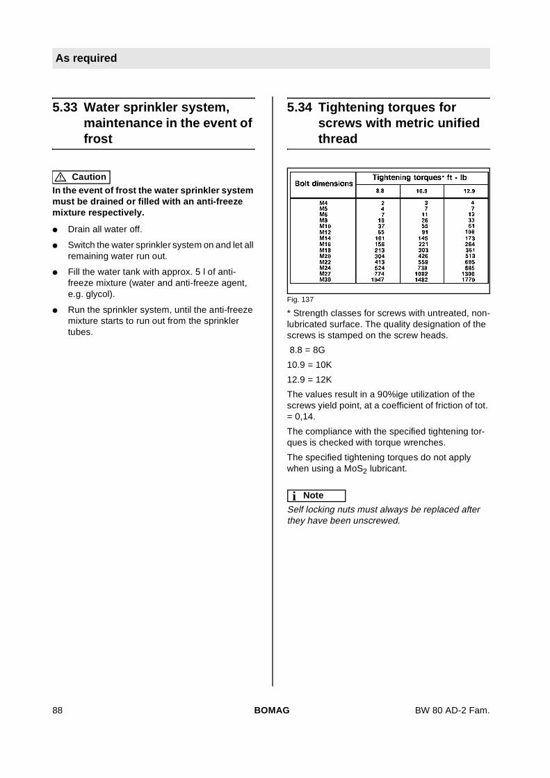
As required
5.33 Water sprinkler system,maintenance in the event offrost
! Caution
In the event of frost the water sprinkler systemmust be drained or filled with an anti-freezemixture respectively.
l Drain all water off.
l Switch the water sprinkler system on and let allremaining water run out.
l Fill the water tank with approx. 5 l of anti-freeze mixture (water and anti-freeze agent,e.g. glycol).
l Run the sprinkler system, until the anti-freezemixture starts to run out from the sprinklertubes.
5.34 Tightening torques forscrews with metric unifiedthread
Fig. 137
* Strength classes for screws with untreated, non-lubricated surface. The quality designation of thescrews is stamped on the screw heads.
8.8 = 8G
10.9 = 10K
12.9 = 12K
The values result in a 90%ige utilization of thescrews yield point, at a coefficient of friction of tot.= 0,14.
The compliance with the specified tightening tor-ques is checked with torque wrenches.
The specified tightening torques do not applywhen using a MoS2 lubricant.
i Note
Self locking nuts must always be replaced afterthey have been unscrewed.
BOMAG88 BW 80 AD-2 Fam.
As required
5.35 Engine conservation
! Caution
Mark a machine with conserved engine by at-taching a clearly visible warning tag.
i Note
Depending on the weather condition these con-serving measures will provide protection for ap-prox. 6 - 12 months.
The conserving oil must be replaced by engine oil(refer to the section "Fuels and lubricants") ac-cording to the API- (MIL) classification before tak-ing the machine into operation.
Anti-corrosion oils are those that comply with thespecification MIL-L-21260 B or TL 9150-037/2 re-sp. Nato Code C 640/642.
If the engine is to be shut down for a longer periodof time (e.g. during winter) we recommend the fol-lowing conservation measures for the engine toavoid corrosion:
l Clean the engine, including the cooling sys-tem: With cold cleansing agent and a water jetor, even better, with steam cleaning equip-ment
l Run the engine warm and shut it down.
l Drain the still warm engine oil and fill in anti-corrosion engine oil.
l Drain the fuel from the fuel tank, mix it well with10% anti-corrosion oil and fill it in again. In-stead of mixing anti-corrosion oil to the fuel thetank may also be filled with injection pumptesting oil with anti-corrosive properties (e.g.Calibration Fluid B).
l Run the engine for 10 minutes until all lines, fil-ter, pump and nozzles are filled with the con-serving mixture and the new engine oil isdistributed to all parts.
l After this run remove the cylinder head coverand spray the rocker chamber with a mixtureof diesel fuel and 10% anti-corrosion oil. Reas-semble the hood.
l Now crank the engine several times (throttlelever in stop-position) to spray the combustionchamber.
l Take the V-belt off and spray the grooves onthe V-belt pulleys with anti-corrosion oil. Re-move the anti-corrosion oil before restartingthe machine.
l Close the air intake opening on the air filterand the exhaust opening.
BOMAG 89BW 80 AD-2 Fam.

As required
BOMAG90 BW 80 AD-2 Fam.

BW 80 AD-2 Fam.
6 Trouble shooting
BOMAG 91

Trouble shooting
6.1 General notes
The following work must only be carried out byqualified and trained personnel or by theBOMAG sales service.
Please observe strictly the safety regulationsin chapter 2 of these operating and mainte-nance instructions.
Malfunctions are frequently caused by incorrectoperation of the machine or insufficient mainte-nance. Whenever a fault occurs you should there-fore thoroughly read these instruction on correctoperation and maintenance. If you cannot locatethe cause of a fault or rectify it yourself by followingthe trouble shooting chart, you should contact theservice departments at our branch offices or deal-ers.
On the following pages you will find a selection offault remedies. It goes without saying that not allpossible reasons for faults could be listed.
! Danger
Danger of injury!
Do not touch rotating parts of the engine.
BOMAG92 BW 80 AD-2 Fam.

Trouble shooting
6.2 Engine
Faults Possible cause Remedy
The enginedoes not start
Fuel tank empty Fill the tank
Fuel filter clogged,in winter due to paraffinseparation
Change the filter Use winter fuel
Fuel lines leaking Check all line connections for leakagesand tighten the fittings.
Travel lever not in "0"-position Move the travel lever to "0"-position
Battery discharged or not connected Charge the battery, check the terminalclamps
Operating error see chapter "Starting the engine"
Incorrect valve clearance Adjust the valve clearance
Lack of oil Top up engine oil
Emergency stop switch is engaged. Emergency stop switch is unlocked.
The enginestarts poorly andworks irregularlywith poor power
Battery power too low Have the battery inspected
Battery clamps loose or oxidized, causingthe starter to turn too slowly
Clean the terminal clamps, tighten themand cover them with acid free grease
Especially during winter: the use of tooviscous engine oil
Use engine oil suitable for the ambienttemperature
Insufficient fuel supply, clogging of thefuel system due to paraffin separation inwinter
Change the fuel filter Check the line con-nections for leaks and tighten the fittings.Use winter fuel in the cold season.
Incorrect valve clearance Adjust the valve clearance
Injection valves or injection pump defec-tive
Have examined by a specialist
Air filter cartridge dirty Clean, change if necessary
Excessive play in the throttle cable Adjust the throttle cable, change it if nec-essary
Engine losespower andspeed, exces-sive exhaustsmoke
Engine oil level too high Drain the oil to the upper dipstick mark
Poor fuel quality Use specified fuel
Air filter dirty Clean, change if necessary
Poor compression due to burned or bro-ken compression rings or incorrect valveclearance
Have compression rings and pistons ex-amined by a specialist, adjust the valveclearance
Injection valve defective Have examined by a specialist
BOMAG 93BW 80 AD-2 Fam.

Trouble shooting
Engine over-heats, shutdown immedi-ately!
Radiator excessively soiled Clean the cooling fins
Coolant level to low Top up coolant.Danger! Only when theengine is cold
Injection valve defective Have examined by a specialist
Engine oil level too low Top up engine oil to the upper dipstickmark
Filling capacity of the injection pump notcorrectly adjusted
Have adjusted by a specialist
Lack of cooling air at the cooling air blow-er
Clean the cooling air duct
V-belt loose or broken Tension or replace the V-belt
Air filter cartridge dirty Clean, change if necessary
Engine oil pres-sure too low,shut down im-mediately
Leakages in the lubrication system, oillevel too low
Check fittings on oil lines, lubrication oil fil-ter for leaks, tighten the fittings if neces-sary. Top up lubrication oil up to the uppermark on the dipstick.
Engine oil of wrong SAE-class Change the engine oil.
The charge con-trol light lightsduring operation
The generator does not charge the bat-tery, because generator or regulator is de-fective
Have examined by a specialist
Faults Possible cause Remedy
BOMAG94 BW 80 AD-2 Fam.


![[1] [2] [9] 3 mm Montageanleitung | Assembly instructions](https://img.dokumen.tips/doc/110x75/62c75fe029cb5f3f6360e608/1-2-9-3-mm-montageanleitung-assembly-instructions-.jpg)