Embed Size (px)
Citation preview

ProM
inen
t®
Part no. 987426 ProMinent Dosiertechnik GmbH · 69123 Heidelberg · Germany BA DM 163 03/08 GB
Please read the operating instructions through completely beforecommissioning this equipment! Do not discard!
The operator shall be liable for any damage caused by installation or operating errors!
Operating InstructionsDULCOMETER® DMTOn-site measurement transducerMeasured variables pH/redox/temperature
Please enter the identity code of the device here.
DMTa ___ ___ ___ ___ ___ ___ ___ ___ ___ ___ ___ ___
BA_DM_163_03_08_GB.p65 26.03.2008, 10:20 Uhr1

ProMinent®Page 2
Publishing details:
Operating InstructionsDULCOMETER® DMT on-site measurement transducerMeasured variables pH/redox/temperature© ProMinent Dosiertechnik GmbH, 2000
Address:
ProMinent Dosiertechnik GmbHIm Schuhmachergewann 5-1169123 HeidelbergGermany
Telephone: +49 6221 842-0Fax: +49 6221 842-419
Subject to technical alterations.
Publishing details
BA_DM_163_03_08_GB.p65 26.03.2008, 10:20 Uhr2

ProMinent® Page 3
Table of contents
Table of contents
Device identification/identity code: measured variable pH .......................... 5
Device identification/identity code: measured variable redox ..................... 6
Device identification/identity code: measured variable temperature .......... 7
1 General instructions for use ............................................................ 8
2 Safety .................................................................................................. 9
2.1 Correct use ............................................................................ 9
2.2 Safety guidelines ................................................................... 9
3 Storage and transport ...................................................................... 9
4 Assembly and installation ................................................................ 10
4.1 Assembly (mechanical) ......................................................... 10
4.1.1 Wall mounting ........................................................................ 10
4.1.2 Pipe mounting ........................................................................ 11
4.1.3 Panel mounting ...................................................................... 12
4.2 Installation (electrical) ........................................................... 13
4.2.1 Wall mounting ........................................................................ 14
4.2.2 Pipe mounting ........................................................................ 15
4.2.3 Panel mounting ...................................................................... 15
4.2.4 Connecting coaxial cable ...................................................... 16
4.2.5 Connecting terminals ............................................................. 16
5 Device overview and control elements .......................................... 17
6 Function description ......................................................................... 18
6.1 General .................................................................................. 18
6.2 Key functions ......................................................................... 19
6.3 Operating menu, schematic .................................................. 19
6.4 Negotiating operating menu ................................................. 20
6.4.1 Calibration menu (pH only) .................................................... 21
6.4.2 Info display ............................................................................ 21
6.4.3 Menu options ......................................................................... 21
6.4.4 Negotiating the menu options ............................................... 21
7 DMT settings ...................................................................................... 22
7.1 Measured variables pH and redox ........................................ 23
BA_DM_163_03_08_GB.p65 26.03.2008, 10:20 Uhr3

ProMinent®Page 4
Table of contents
7.1.1 Menu overview: measured variable pH ................................ 23
7.1.2 Menu overview: measured variable redox ............................ 24
7.1.3 Parameter settings (pH only) ................................................ 25
7.1.4 Checking the ORP probe (redox only) .................................. 25
7.1.5 Parameters: Temperature ...................................................... 26
7.1.6 Parameter output .................................................................. 28
7.1.7 General settings .................................................................... 31
7.2 Measured variable temperature ............................................ 33
7.2.1 Menu overview measured variable, temperature ................. 33
7.2.2 Parameters temperature ....................................................... 34
7.2.3 Parameter output .................................................................. 34
7.2.4 General settings .................................................................... 36
8 Operating the DMT ............................................................................ 38
8.1 Permanent display ................................................................ 38
8.1.1 Probe condition information (pH only) ................................... 38
8.1.2 Brightness of LC display ........................................................ 39
8.2 Calibrating the pH meter ....................................................... 39
8.2.1 Automatic buffer detection .................................................... 39
8.2.2 The calibration process ......................................................... 40
9 Troubleshooting ................................................................................. 44
9.1 Error messages during operation ......................................... 44
9.2 Error messages while calibrating the pH meter ................... 45
10 Maintenance and repair .................................................................... 46
11 Disposal .............................................................................................. 46
12 Technical data .................................................................................... 47
13 Spare parts and accessories ........................................................... 48
Appendix ............................................................................................. 49
Conformity declarationdeclaration ...................................................... 49
Terminal connection plan pH/redox/temperature ................................ 50
Wiring example - two wire system ....................................................... 51
PROFIBUS® circuit board terminal connection ................................... 52
Index .................................................................................................... 53
BA_DM_163_03_08_GB.p65 26.03.2008, 10:20 Uhr4

ProMinent® Page 5
Device identification/identity code: measured variable pH
Please enter the identity code for your device here.
DMTa 0 P 1 0 0
DMTa DULCOMETER® DMT series measurement transducer
Mounting typeW wall/pipe mountedS control panel mounted (not PROFIBUS®-DMT)
Version0 with ProMinent logo
Electrical connection9 4-20 mA (two wire) current loop, 24 V DC (16...40 V DC)5 PROFIBUS®-DP, 24 V DC (16...30 V DC)
Communication interface0 none4 PROFIBUS®-DP
Measured variableP pHR redox (ORP)T temperature
Correction variable1 temperature (PT 1000/PT 100)
Enclosure rating0 standard
Adjustable general settings:
LanguageD GermanE EnglishF FrenchP PolishS SpanishI Italian
Automatic buffer detection0 ProMinent buffer setD DIN 19226 buffer setV automatic buffer adjustment
Temperature measurement0 automatic
(PT 1000 or PT 100)1 manual2 automatic or manual9 none
Output0 measured variable
(fault: 23 mA, calibration: 23 mA)1 manually adjustable
current value2 measured variable or manual
(fault: 23 mA, calibration: 23 mA)3 measured variable or manual
(fault: 23 mA, calibration: HOLD)4 4 mA constant current
Other settings0 standard
BA_DM_163_03_08_GB.p65 26.03.2008, 10:20 Uhr5

ProMinent®Page 6
Device identification/identity code: measured variable redox
Please enter the identity code for your device here.
DMTa 0 R 1 0 0 0
DMTa DULCOMETER® DMT series measurement transducer
Mounting typeW wall/pipe mountedS control panel mounted (not PROFIBUS®-DMT)
Version0 with ProMinent logo
Electrical connection9 4-20 mA (two wire) current loop, 24 V DC (16...40 V DC)5 PROFIBUS®-DP, 24 V DC (16...30 V DC)
Communication interface0 none4 PROFIBUS®-DP
Measured variableR redoxP pHT temperature
Correction variable1 temperature (PT 1000/PT 100) - measurement only
Enclosure rating0 standard
Adjustable general settings:
LanguageD GermanE EnglishF FrenchP PolishS SpanishI Italian
Probe type0 standard
Temperature measurement0 automatic
(PT 1000 or PT 100)9 none
Output0 measured variable
(fault: 23 mA, calibration: 23 mA)1 manually adjustable
current value2 measured variable or manual
(fault: 23 mA, calibration: 23 mA)3 measured variable or manual
(fault: 23 mA, calibration: HOLD)4 4 mA constant current
Other settings0 standard
BA_DM_163_03_08_GB.p65 26.03.2008, 10:20 Uhr6

ProMinent® Page 7
Please enter the identity code for your device here.
DMTa 0 T 0 0 0 0 0
DMTa DULCOMETER® DMT series measurement transducer
Mounting typeW wall/pipe mountedS control panel mounted (not PROFIBUS®-DMT)
Version0 with ProMinent logo
Electrical connection9 4-20 mA (two wire) current loop, 24 V DC (16...40 V DC)5 PROFIBUS®-DP, 24 V DC (16...30 V DC)
Communication interface0 none4 PROFIBUS®-DP
Measured variableP pHR redox (ORP)T temperature
Correction variable0 none
Enclosure rating0 standard
Adjustable general settings:
LanguageD GermanE EnglishF FrenchP PolishS SpanishI Italian
Probe type0 PT 100 or PT 1000
Temperature detection0 Probe (PT 1000 or PT 100)
Output current0 Output: measured variable
(fault: 23 mA, calibration: 23 mA)1 Output adjustable2 measured variable or adjustable
(fault: 23 mA, calibration: 23 mA)3 measured variable + manual + HOLD
(fault: 23 mA, calibration: HOLD)4 Output current = 4 mA
Other settings0 standard
Device identification/identity code: measured variable temperature
BA_DM_163_03_08_GB.p65 26.03.2008, 10:20 Uhr7

ProMinent®Page 8
1 General instructions for use
Please read through these instructions for use carefully. They will enable youto make the best possible use of this operating instructions manual.
The following sections are highlighted in the text:
• Enumerated points Instructions
Working instructions
NOTE
Guidelines are intended to make your work easier.
and safety instructions:
CAUTION
Describes a potentially dangerous situation.Non-observance can lead to personal injury or damageto property.
IMPORTANT
Describes a potentially dangerous situation.Non-observance can lead to damage to property.
General instructions for use
BA_DM_163_03_08_GB.p65 26.03.2008, 10:20 Uhr8

ProMinent® Page 9
2 Safety
2.1 Correct use
The DMT on-site measurement transducer is designed exclusively for the• measurement of pH value resp. redox potential• measurement of temperature• display of measured variables• production of an output signal
It is prohibited to use the device for any other applications or to modify itin any way!The device must not be used outdoors without added protection (housing,weatherproof cover).
2.2 Safety guidelines
CAUTION
• The device must not be used in a possible explosionarea.
• The DMT must be operated by trained and authorisedpersonnel.
IMPORTANT
• The system must be suitably equipped and configured toprevent overdosing of hazardous materials due to probefailure.
• The DMT has no on/off switch. It starts to function as soonas it is connected to a power supply.
3 Storage and transport
Store and transport the DMT in the original packaging.
IMPORTANT
• Protect the DMT from damp and the effects of chemicalseven when packed.
Ambient conditions for storage and transport:
Temperature: -20 °C to 70 °CHumidity: max. 95 % relative humidity,
non condensing
Safety / Storage and transport
BA_DM_163_03_08_GB.p65 26.03.2008, 10:20 Uhr9

ProMinent®Page 10
4 Assembly and installation
IMPORTANT
• The DMT is fully resistant to normal environments controlrooms.
• The DMT must not be placed where it can come intocontact with rain or direct sunlight!Use a protective housing or weatherproof cover if in useout of doors.
4.1 Assembly (mechanical)
The DMT can be wall, pipe or panel mounted (not for PROFIBUS®-DMT).
4.1.1 Wall mounting
Mounting materials (included in delivery):
1 x wall/pipe bracket2 x 5x45 mm round headed screws2 x 5.3 washers2 x wall plugs Ø 8 mm, plastic1 x rubber insert1 x locking screw (PT)
Wall mounting, please follow the steps below:
Remove wall/pipe bracket from DMT:pull the two snap fasteners outwards and push upwards (fig. 1, ➀).Swing the wall/pipe bracket away from the DMT and pull downwards(fig. 1, ➁).
Mark two drill holes diagonally opposite one another using the mountingbracket as a template.
Drill the holes: Ø 8 mm, depth = 50 mm.
Screw the wall/pipe bracket in place inserting the washers (fig. 2).
If the DMT is also to be secured with a screw, pierce the screw hole in theback of the housing (housing must be open) and attach a rubber insert(fig. 2, ➀) to the bracket.
Hang the DMT onto the top of the bracket (fig. 3, ➀) and push downgently against the bracket (fig. 3, ➁), then push upwards until you heara click (fig. 3, ➂).
Tighten the locking screw to secure more firmly (housing is open).
Assembly and installation
BA_DM_163_03_08_GB.p65 26.03.2008, 10:20 Uhr10

ProMinent® Page 11
Fig. 1 Fig. 2
2
3515_4
1
1
3461_4
Fig. 3
3
2
1
3464_4
4.1.2 Pipe mounting
Mounting materials (included in delivery):
1 x wall/pipe bracket2 x cable ties1 x sealing cap1 x locking screw (PT)
Can be mounted onto pipes of diameters from 25 mm to 60 mm.
Assembly and installation
BA_DM_163_03_08_GB.p65 26.03.2008, 10:20 Uhr11

ProMinent®Page 12
Pipe mounting, please follow the steps below:
Remove wall/pipe bracket from DMT:pull the two snap fasteners outwards and push upwards (fig. 1, ➀).Swing the wall/pipe bracket away from the DMT and pull downwards(fig. 1, ➁).
Fasten the bracket to the pipe using the cable ties or pipe clamps (fig. 3). If the DMT is also to be secured with a screw, pierce the screw hole in the
back of the housing (housing must be open) and attach a rubber insert(fig. 2, ➀) to the bracket.
Hang the DMT onto the top of the bracket (fig. 3, ➀) and push downgently against the bracket (fig. 3, ➁), then push upwards until you hear aclick (fig. 3, ➂).
Tighten the locking screw to secure more firmly (housing is open).
4.1.3 Panel mounting
IMPORTANT
• The control panel must be thick enough to withstand theweight of the mounted DMT without buckling. (To achieveenclosure rating IP 54, steel must be at least 2 mm thick;plastic should be correspondingly thicker).
NOTE
The DMT will protrude from the control panel approx. 30 mmonce mounted.
Fig. 4
3463_4
Assembly and installation
BA_DM_163_03_08_GB.p65 26.03.2008, 10:20 Uhr12
ProMinent® Page 13
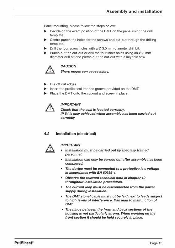
Panel mounting, please follow the steps below:
Decide on the exact position of the DMT on the panel using the drilltemplate.
Centre punch the holes for the screws and cut-out through the drillingtemplate.
Drill the four screw holes with a Ø 3.5 mm diameter drill bit. Punch out the cut-out or drill the four inner holes using an Ø 8 mm
diameter drill bit and pierce out the cut-out with a keyhole saw.
CAUTION
Sharp edges can cause injury.
File off cut edges. Insert the profile seal into the groove provided on the DMT. Place the DMT onto the cut-out and screw in place.
IMPORTANT
Check that the seal is located correctly.IP 54 is only achieved when assembly has been carried outcorrectly.
4.2 Installation (electrical)
IMPORTANT
• Installation must be carried out by specially trainedpersonnel.
• Installation can only be carried out after assembly has beencompleted.
• The device must be connected to a protective low voltagein accordance with EN 60335-1.
• Observe the relevant technical data in chapter 12throughout installation procedures.
• The current loop must be disconnected from the powersupply during installation.
• The DMT signal cable must not be laid next to leads subjectto high levels of interference. Can lead to malfunction ofDMT.
• The hinge between the front and back sections of thehousing is not particularly strong. When working on thefront section it should be held securely in place.
Assembly and installation
BA_DM_163_03_08_GB.p65 26.03.2008, 10:20 Uhr13
ProMinent®Page 14
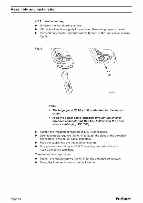
4.2.1 Wall mounting
Unfasten the four housing screws Lift the front section slightly forwards and then swing open to the left. Pierce threaded cable apertures at the bottom of the rear side as required
(fig. 5).
Fig. 5
3468_4
NOTE
• The large gland (M 20 x 1.5) is intended for the sensorcable.
• Feed the power cable leftwards through the smallerthreaded connector (M 16 x 1.5). Follow with the othersensor cables (e.g. PT 1000).
Tighten the threaded connectors (fig. 6, ➀) as required. Use reducers as required (fig. 6, ➁) to adapt the sizes of the threaded
connectors to the actual cable diameters. Feed the cables into the threaded connectors. Now proceed according to 4.2.4 Connecting coaxial cable and
4.2.5 Connecting terminals.
Then follow the steps below:
Tighten the locking screws (fig. 6, ➂) for the threaded connectors. Swing the front section onto the back section.
Assembly and installation
BA_DM_163_03_08_GB.p65 26.03.2008, 10:20 Uhr14

ProMinent® Page 15
IMPORTANT
Check that the seal is located correctly. IP 65 is achieved onlywhen assembly has been carried out correctly.
(If necessary pull the front section forward in order to reducethe stress on the seal.)
Tighten the housing screws finger tight.
Fig. 6
Cl/ClO /OCl/ClO /O32
--
++4to20mA4to20mA
shie
ldsh
ield
(gr) Pt1000 - /sig.gnd.
(gr) Pt1000 - /sig.gnd.
(wth) Pt1000 +(wth) Pt1000 +
(bl) +U(bl) +U------
(blk)-U(blk)-U
(br) meas.sig.(br) meas.sig.
Pt100x -Pt100x -
Pt100x +Pt100x +
------
liquid pot.liquid pot.
rref.el.ef.el.glass el.glass el.
pH/ORpH/ORPP
8866
55
44
33
2
77
11
3465_3
1
2
3
4
4.2.2 Pipe mounting
See 4.2.1 Wall mounting
4.2.3 Panel mounting
NOTE
The cable must be laid in cable ducting on site to minimisestresses.
Connect the cable from the back through the cut-out in the control panel:
Follow the steps given in 4.2.4 Connecting coaxial cable and 4.2.5Connecting terminals.
Assembly and installation
BA_DM_163_03_08_GB.p65 26.03.2008, 10:20 Uhr15

ProMinent®Page 16
4.2.4 Connecting coaxial cable
The pH resp. redox probe is connected via a coaxial cable:
Strip back to reveal cable shield (reference electrode) in accordance withfig. 7 (left) and clamp using the shield clip.
The shield clip is connected internally to terminal 3.
Under normal circumstances measuring can be carried out withoutconnecting a liquid reference potential. In this case provide wire jumpersbetween terminals 1 and 2.
When electrical conditions are more complex a potential plug should beconnected to terminal 1. Terminal 2 is left free.
The appendix contains an overview of connection options (terminalconnection plan).
4.2.5 Connecting terminals
Remove insulation from cable ends as shown in fig. 7 (right) and attachend crimps to each core.
Connect the cables in accordance with the terminal connection plan.
IMPORTANT
• Do not operate PROFIBUS® variants at voltages over 30 V.
• Connect PROFIBUS® variant power supplies via terminals 3and 4 on the PROFIBUS® circuit board in the back section,not terminals 7 and 8 in the front section.
NOTE
• The terminal connection plan is given in the appendix.There is also a panel giving connection information affixedto the housing near the terminals (fig. 6, and fig. 8).
• Push the cable through the housing until the front sectioncan be moved up and down easily.
• If the LC display is too weak, reduce the brightness usingthe up arrow key . If the display is too dark, increase thebrightness using the down arrow key .
Fig. 7 Fig. 8
3312
30
77
3459_4
Cl/ClO /O32
-
+4to20mA
shie
ld
(gr) Pt1000 - /sig.gnd.
(wth) Pt1000 +
(bl) +U
---
(blk)-U
(br) meas.sig.
Pt100 -
Pt100 +
---
liquid pot.
ref.el.
glass el.
pH/ORP
8
6
5
4
3
2
7
1
Assembly and installation
BA_DM_163_03_08_GB.p65 26.03.2008, 10:20 Uhr16

ProMinent® Page 17
5 Device overview and control elements
Fig. 9
3456_4
Device overview and control elements
Change keyCAL key
Measuredvariable label
LC-Display
Down key
Back keyEnter Key
Up key
BA_DM_163_03_08_GB.p65 26.03.2008, 10:20 Uhr17

ProMinent®Page 18
6 Function description
6.1 General
The DULCOMETER® MEASUREMENT TRANSDUCER (DMT) is a micro-processor controlled on site measurement transducer. It displays theselected measured variable and produces a proportional output signal. It canalso use temperature as a correction variable. The user can specify thesefunctions using the operating menu.
The user can switch between the measured variables pH value, redoxpotential and temperature.
The inputs are collectively electrically insulated against the output.
In the event of a fault the DMT indicates an error message on the LC displayand produces an increased current (23 mA) through the ring circuit.
The DMT is also available for the following measured variables:
• Conductivity• Chlorine
Block circuit diagram
Function description
Signaloutput
4 ... 20 mA
at16 ... 40 V DC
and/or30 V DC
(PROFIBUS®
variant)
µP
Keypad LC display
EEPROM(parameter memory)
DA
AD
Measuredvariable
temperatureFlashROM(program memory)
Power supply,current control
BA_DM_163_03_08_GB.p65 26.03.2008, 10:20 Uhr18

ProMinent® Page 19
6.2 Key functions
The key are used to alter the DMT settings and have the followingfunctions:
In the permanent display / In the menu optionsin the info display
Change key Toggles between permanent Scrolls through values of thedisplay and info display current menu optionmodes
Back key Exits info display mode and Exits to info display withoutreturns to permanent display saving changes to valuesmode
Enter key Accesses menu option Saves changes to values in(from an info display) current menu option and
accesses the next infodisplay or another menuoption
CAL key Opens the calibration menu Activates calibration in(from permanent display) calibration menu (pH only)
Down key Alters brightness of the Changes a valueLC display
Up key (in permanent display mode)
6.3 Operating menu, schematic
The operating menu comprises:
• the permanent display
• the calibration menu
• the info displays (info level)for the display of pre-set parameters resp. general settings
• menu options (settings level)for altering parameters resp. general settings
Function description
BA_DM_163_03_08_GB.p65 26.03.2008, 10:20 Uhr19
ProMinent®Page 20
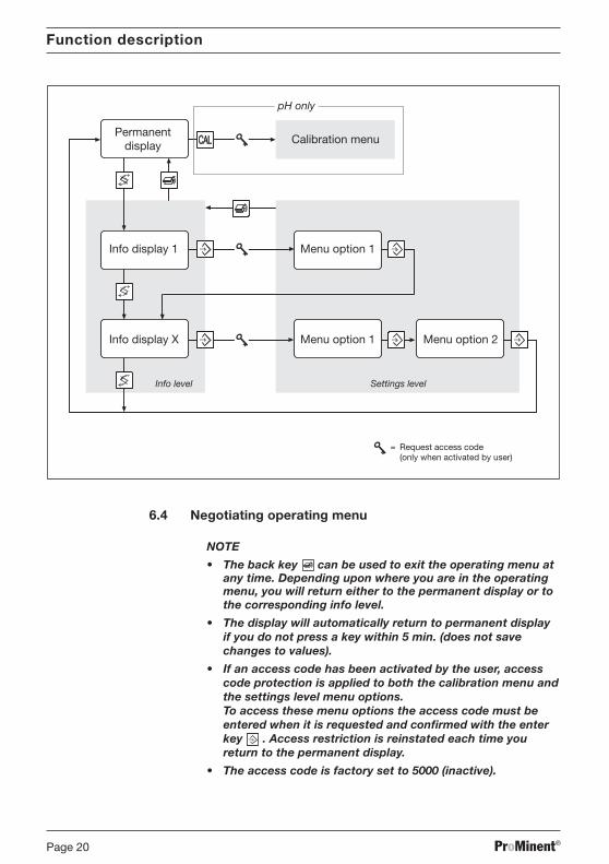
6.4 Negotiating operating menu
NOTE
• The back key can be used to exit the operating menu atany time. Depending upon where you are in the operatingmenu, you will return either to the permanent display or tothe corresponding info level.
• The display will automatically return to permanent displayif you do not press a key within 5 min. (does not savechanges to values).
• If an access code has been activated by the user, accesscode protection is applied to both the calibration menu andthe settings level menu options.To access these menu options the access code must beentered when it is requested and confirmed with the enterkey . Access restriction is reinstated each time youreturn to the permanent display.
• The access code is factory set to 5000 (inactive).
= Request access code(only when activated by user)
Calibration menu
pH only
Info display 1
Info display X
Menu option 1
Menu option 1
Permanentdisplay
Menu option 2
Info level Settings level
Function description
BA_DM_163_03_08_GB.p65 26.03.2008, 10:20 Uhr20

ProMinent® Page 21
6.4.1 Calibration menu (pH only)
Access the calibration menu from the permanent menu using the CAL key (further details given in 8.2 Calibrating the pH meter)
6.4.2 Info display
Access the first info display of the info level from the permanent display usingthe change key .
Use the change key to access the other info displays in turn. Returns tothe permanent display after the last info display.
6.4.3 Menu options
Use the enter key to access the menu options associated with that infolevel.
6.4.4 Negotiating the menu options
= adjustable numericalvalues/texts flashing
input: sensorunit: ˚Coffset = 0.00 ˚Cmeas. val. = 21.00 ˚C
Press the change key to activate all adjustable values in a menu option.Flashing values can be altered. Use the arrow keys / to alter numericalvalues or texts.Keystrokes perform the following actions:
• 1 x short keystroke reduces/increases a numerical value by oneincrement or alters a text
• Holding the key down for longer alters numerical values increasinglyrapidly.
Use the enter key to save changed values in the menu option. You willthen automatically enter the next info display or (if available) the next menuoption.
NOTE
Your entries become active immediately and are storedpermanently when you press the enter key .
If you do not wish to save changes, exit the menu option using the backkey . You will then return to the info display for that menu.
Function description
BA_DM_163_03_08_GB.p65 26.03.2008, 10:20 Uhr21

ProMinent®Page 22
DMT settings
7 DMT settings
NOTE
• Settings need only be changed if your processrequirements differ from factory general settings.
• If your DMT does not display the required settings option,check the general settings of your device as described inchapter 7.1.7.
Menu overview table
pH probe parameters Zero point, slope and proberesistance
Redox probe test Compare with buffer Probe resistance
Parameter Detection means:Temperature • sensormeasurement • manual (enter value)
Unit of measurement• °C• °F
Parameter Value:Output current • proportional measured variable:
measured variable at 4 mAmeasured variable at 20 mA
• manual (enter value)
General settings Measured variable: Settings configuration Access• pH code• ORP (redox)• temperature
Permanent display Calibration of pH probe Zero point and slope
= Request access code(if activated by the user)
BA_DM_163_03_08_GB.p65 26.03.2008, 10:20 Uhr22

ProMinent® Page 23
7.1 Measured variables pH and redox
7.1.1 Menu overview: measured variable pH
NOTE
The following menu is only an example.The displays can vary depending upon the general settings.
DMT settings
pH
param. measurementzero point. = -0.1 mVslope = 60.30 mV/pHprobe check: on
zero point = -0.1 mVslope = 60.30 mV/pHprobe check: onmeas. val. = 7.12 pH
param. output signaloutput: meas. value 4 mA: 2.00 pH20 mA: 12.00 pH
output: meas. value 4 mA: 2.00 pH20 mA: 12.00 pH
general settingsDMTaW090P10E0220
2.1.06
device type!! correct probe ??type = pHDMTaW090P10E0220
general settingslanguageDMTaW090P10E0220E = english
param. temperatureinput: sensorunit: ˚C
pH
12.5 mA 21.0 ˚C7.12 = Request access code
(if activated by the user)
input: sensorunit: ˚Coffset = 0.00 ˚Cmeas. val. = 21.00 ˚C
general settingschangeaccess code = 5000
free access
BA_DM_163_03_08_GB.p65 26.03.2008, 10:20 Uhr23

ProMinent®Page 24
7.1.2 Menu overview: measured variable redox
NOTE
The following menu is only an example.The displays can vary depending upon the general settings.
DMT settings
Redox
param. output signaloutput: meas. value 4 mA: 0 mV20 mA: 1000 mV
= Request access code(if activated by the user)
mV
12.5 mA 21.0 ˚C312
checking ORP-probe probe in buffer!faulty probe!!
buffer value: 465 mVmeas. value: 509 mV
check dry proberesistance = 1.23 MΩallowed > 2 MΩ
faulty probe !!
general settingsDMTaW090R10E00220
2.1.06
general settingslanguageDMTaW090R10E0220E = english
param. temperatureinput: sensorunit: ˚C
device type!! correct probe ??type = ORP (Redox)DMTaW090R10E0220
unit: °Coffset = 0.00 °C
meas. val. = 21.00 °C
output: meas. value 4 mA: 0 mV20 mA: 1000 mV
general settingschangeaccess code = 5000
free access
BA_DM_163_03_08_GB.p65 26.03.2008, 10:20 Uhr24
ProMinent® Page 25
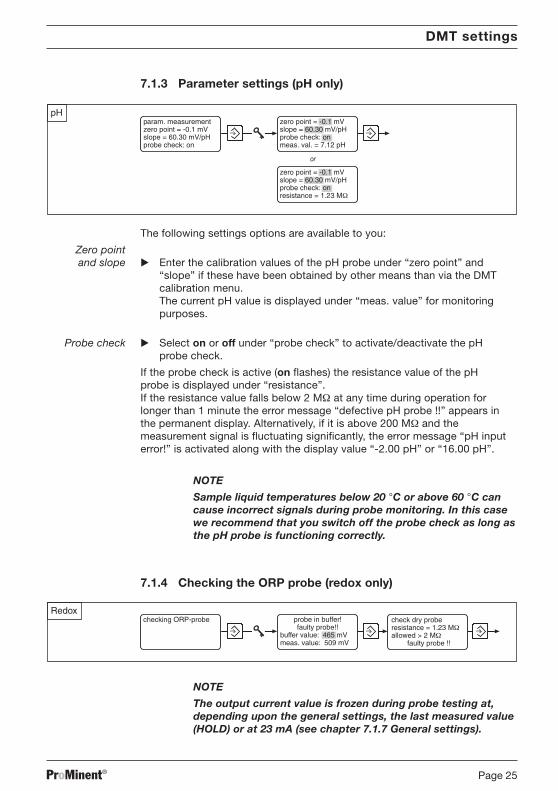
7.1.3 Parameter settings (pH only)
pH
zero point = -0.1 mVslope = 60.30 mV/pHprobe check: onresistance = 1.23 MΩ
param. measurementzero point = -0.1 mVslope = 60.30 mV/pHprobe check: on
zero point = -0.1 mVslope = 60.30 mV/pHprobe check: onmeas. val. = 7.12 pH
or
The following settings options are available to you:
Zero point and slope Enter the calibration values of the pH probe under “zero point” and
“slope” if these have been obtained by other means than via the DMTcalibration menu.The current pH value is displayed under “meas. value” for monitoringpurposes.
Probe check Select on or off under “probe check” to activate/deactivate the pHprobe check.
If the probe check is active (on flashes) the resistance value of the pHprobe is displayed under “resistance”.If the resistance value falls below 2 MΩ at any time during operation forlonger than 1 minute the error message “defective pH probe !!” appears inthe permanent display. Alternatively, if it is above 200 MΩ and themeasurement signal is fluctuating significantly, the error message “pH inputerror!” is activated along with the display value “-2.00 pH” or “16.00 pH”.
NOTE
Sample liquid temperatures below 20 °C or above 60 °C cancause incorrect signals during probe monitoring. In this casewe recommend that you switch off the probe check as long asthe pH probe is functioning correctly.
7.1.4 Checking the ORP probe (redox only)
Redoxchecking ORP-probe probe in buffer!
faulty probe!!buffer value: 465 mVmeas. value: 509 mV
check dry proberesistance = 1.23 MΩallowed > 2 MΩ
faulty probe !!
NOTE
The output current value is frozen during probe testing at,depending upon the general settings, the last measured value(HOLD) or at 23 mA (see chapter 7.1.7 General settings).
DMT settings
BA_DM_163_03_08_GB.p65 26.03.2008, 10:20 Uhr25

ProMinent®Page 26
Two different test options are available:
Comparisonwith buffer You can check the probe in the first menu option by measuring the redox
potential of a buffer solution:
The suggested “buffer value” (the redox potential for the buffer solution) is220 mV or 465 mV. This value can be changed. The device compares thebuffer value with the measured variable and displays an error message“faulty probe !!” if the difference is greater than 40 mV.
Proberesistance The probe can be checked in the second menu option by measuring the
electrical resistance between the electrodes of the probe (must be dry):
It is particularly important that there is no residual moisture adhering to theprobe.If the resistance measured is less than 2 MΩ the device will display the errormessage “faulty probe !!”.
7.1.5 Parameters: Temperature
NOTE
• The DMT automatically detects whether a PT 1000 orPT 100 is connected.
• If there is no temperature gauge connected thetemperature measurement should be set to “none”or “manual” (see chapter 7.1.7 General settings).
Depending upon the “temp. meas.” general setting you have the followingoptions:
7.1.5.1 General setting: Temperature measurement = automatic
Select the unit of measurement for temperature °C or °F under “unit”. Enter the difference ∆t under “offset” to a reference temperature
measurement (see chapter 7.5.5 Calibrating the Pt 100 temperaturegauge).
The actual temperature measured is displayed under “meas. val.”.
DMT settings
BA_DM_163_03_08_GB.p65 26.03.2008, 10:20 Uhr26

ProMinent® Page 27
7.1.5.2 General setting: Temperature measurement = manual(pH only)
pHT = 22.6 ˚Cunit: ˚C
param. temperatureinput: manualunit: ˚C
Enter the process temperature under “T”. Select the temperature unit °C or °F under “unit”.
7.1.5.3 General setting: Temperature measurement = automatic ormanual (pH only)
pHinput: sensorunit: ˚Coffset = 0.00 ˚Cmeas. val. = 21.00 ˚C
or
param. temperatureinput: manualunit: ˚C
input: manualT = 22.6 ˚CUnit: ˚C
Under “input” select sensor or manual:Select sensor if a temperature gauge is connected (temperaturemeasurement = automatic):Select manual if the user is going to enter the process temperature(temperature measurement = manual).
The selection made under “input” affects subsequent settings options.
Sensor If you have selected sensor in the “input” option:
Select the unit of measurement for temperature °C or °F under “unit”. Enter the difference ∆t under “offset” to a reference temperature
measurement (see 7.1.5.5 Calibrating the Pt 100 temperature gauge).
The actual temperature measured is displayed under “meas. val.”.
Manual If you have selected manual in the “input” option:
Enter the process temperature under “T”. Select the temperature unit °C or °F under “unit”.
7.1.5.4 General setting: Temperature measurement = none
No info display appears in the operating menu.
No temperature measurement is carried out.
DMT settings
BA_DM_163_03_08_GB.p65 26.03.2008, 10:20 Uhr27
ProMinent®Page 28
7.1.5.5 Calibrating the PT 100 temperature gauge
NOTE
You need only calibrate the temperature gauge if
- You have a PT 100 temperature gauge and the sensor cableis longer than 4 m.
- You have a precision measurement device (the DMTmeasures to ±0.5 °C / ±0.9 °F accuracy).
• Do not replace the temperature sensor during calibration!
Immerse the DMT temperature gauge and the reference measurementdevice into the same liquid sample.
Read off the value from the reference measurement device once thetemperature is stable.
Set the correction value under “offset” until the temperature value isidentical to the reference value.
7.1.6 Parameter output
Depending upon the “output” general setting you have the following settingsoptions:
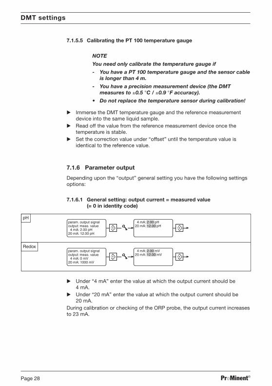
7.1.6.1 General setting: output current = measured value(= 0 in identity code)
Under “4 mA” enter the value at which the output current should be4 mA.
Under “20 mA” enter the value at which the output current should be20 mA.
During calibration or checking of the ORP probe, the output current increasesto 23 mA.
DMT settings
BA_DM_163_03_08_GB.p65 26.03.2008, 10:20 Uhr28
ProMinent® Page 29
DMT settings
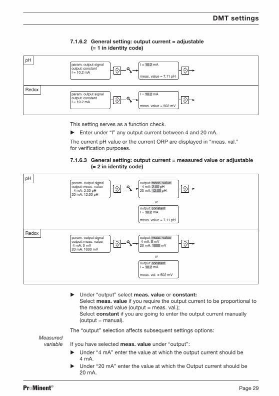
7.1.6.2 General setting: output current = adjustable(= 1 in identity code)
This setting serves as a function check.
Enter under “l” any output current between 4 and 20 mA.
The current pH value or the current ORP are displayed in “meas. val.”for verification purposes.
7.1.6.3 General setting: output current = measured value or adjustable(= 2 in identity code)
pH
Redoxoutput: meas. value 4 mA: 0 mV20 mA: 1000 mV
output: constantI = 10.2 mA
meas. val. = 502 mV
param. output signaloutput: meas. value 4 mA: 0 mV20 mA: 1000 mV
output: constantI = 10.2 mA
meas. value = 7.11 pH
or
or
param. output signaloutput: meas. value 4 mA: 2.00 pH20 mA: 12.00 pH
output: meas. value 4 mA: 2.00 pH20 mA: 12.00 pH
Under “output” select meas. value or constant:Select meas. value if you require the output current to be proportional tothe measured value (output = meas. val.);Select constant if you are going to enter the output current manually(output = manual).
The “output” selection affects subsequent settings options:Measured
variable If you have selected meas. value under “output”:
Under “4 mA” enter the value at which the output current should be4 mA.
Under “20 mA” enter the value at which the Output current should be20 mA.
BA_DM_163_03_08_GB.p65 26.03.2008, 10:20 Uhr29

ProMinent®Page 30
DMT settings
Constant If you have selected constant under “output”
Enter under “l” any output current between 4 and 20 mA.
The current pH/redox value is displayed under “meas. value” formonitoring purposes.
This setting serves as a function check. During calibration or checking of theORP probe, the output current increases to 23 mA.
7.1.6.4 General setting: output current = measured value + adjustable +HOLD(= 3 in identity code)
In this general setting, the DMT can be adjusted as shown in 7.1.6.1 or7.1.6.3. The following differences should be noted:
pH
For DMT pH, the output current remains at the output current value lastreported (HOLD function) during calibration. The output current freezes themoment the menu option “input” is exited using the CAL key. This outputcurrent corresponds to the last measured pH value. The HOLD value of theoutput current is held until the calibration is completed. It is also possible toset a certain HOLD value in the first measuring point of the calibration menu(see 8.2.2).
Redox
With regard to DMT redox, the output current increases during calibration ofthe ORP probe to the output current value last displayed (HOLD function)upon activation of the ENTER key. This output current corresponds to the lastmeasured redox value. The HOLD value of the output current is held until themenu “checking of redox probe” is exited.
7.1.6.5 General setting: output = 4 mA(= 4 in identity code)
No info display appears in the operating menu.
The DMT emits a constant output current of 4 mA.
This setting serves as a function check and is selected if the DMT is to beused purely as a display device (current consumption is minimal in this case!).
BA_DM_163_03_08_GB.p65 26.03.2008, 10:20 Uhr30

ProMinent® Page 31
DMT settings
pH Redoxgeneral settingsDMTaW090P10E0220
2.1.06
device type!! correct probe ??type = pHDMTaW090P10E0220
general settingslanguageDMTaW090P10E0220E = english
general settingschangeaccess code = 5000
free access
7.1.7 General settings
7.1.7.1 Changing the device type
You can select the measured variables, pH or redox potential, in the firstmenu option “device type”. Under “type” select pH or ORP (redox).
Depending upon your choice the corresponding identity code position alters:pH = “P”, redox = “R”.If you have confirmed the change of measured variable with the enter key the output current will change immediately.The settings for each measured variable are unaffected even after a differentselection has been made and are reinstated if the selection is reversed.
7.1.7.2 Changing general settings
You can adapt the DMT to your individual process requirements in thesecond menu option “general settings”.Access the individual identity code positions using the change key .Non-alterable features are automatically bypassed.
The following tables show the settings options depending upon the selectedmeasured value (the sequence from left to right corresponds to the identitycode position).
Measured variable pH
Language Automatic buffer Temperature Output Otherdetection measurement settings
D = German 0 = ProMinent 0 = automatic 0 = measured variable; 0 = standardE = English buffer set 1 = manual fault 23 mA,F = French D = DIN 19266 2 = automatic or at calibration 23 mAP = Polish buffer set manual 1 = manually adjustableI = Italian V = automatic 9 = none current valueS = Spanish adjustment 2 = measured variable
or manual:at fault 23 mA,at calibration 23 mA
3 = measured variableor manual:at fault 23 mA,when calibrating the lastmeasured value (HOLD)
4 = constant 4 mAcurrent
BA_DM_163_03_08_GB.p65 26.03.2008, 10:20 Uhr31
ProMinent®Page 32
DMT settings
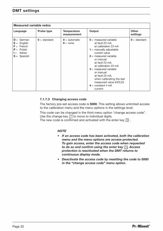
Measured variable redox
Language Probe type Temperature Output Othermeasurement settings
D = German 0 = standard 0 = automatic 0 = measured variable: 0 = standardE = English 9 = none at fault 23 mA,F = French at calibration 23 mAP = Polish 1 = manually adjustableI = Italian current valueS = Spanish 2 = measured variable
or manual:at fault 23 mA,at calibration 23 mA
3 = measured variableor manual:at fault 23 mA,when calibrating the lastmeasured value (HOLD)
4 = constant 4 mAcurrent
7.1.7.3 Changing access code
The factory pre-set access code is 5000. This setting allows unlimited accessto the calibration menu and the menu options in the settings level.
This code can be changed in the third menu option “change access code”.Use the change key to move to individual digits.The new code is confirmed and activated with the enter key .
NOTE
• If an access code has been activated, both the calibrationmenu and the menu options are access-protected.To gain access, enter the access code when requestedto do so and confirm using the enter key . Accessprotection is reactivated when the DMT returns tocontinuous display mode.
• Deactivate the access code by resetting the code to 5000in the “change access code” menu option.
BA_DM_163_03_08_GB.p65 26.03.2008, 10:20 Uhr32
ProMinent® Page 33
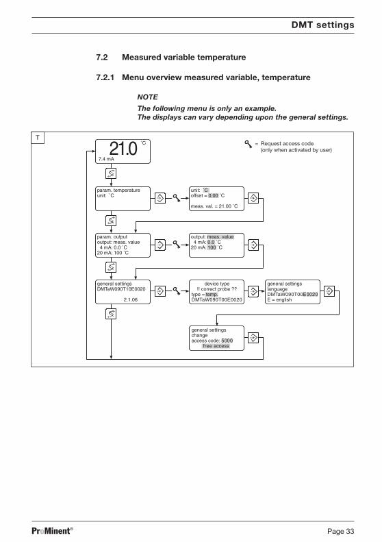
7.2 Measured variable temperature
7.2.1 Menu overview measured variable, temperature
NOTE
The following menu is only an example.The displays can vary depending upon the general settings.
DMT settings
T
param. outputoutput: meas. value 4 mA: 0.0 ˚C20 mA: 100 ˚C
general settingsDMTaW090T10E0020
2.1.06
general settingslanguageDMTaW090T00E0020E = english
param. temperatureunit: ˚C
˚C
7.4 mA21.0 = Request access code
(only when activated by user)
unit: ˚Coffset = 0.00 ˚C
meas. val. = 21.00 ˚C
general settingschangeaccess code: 5000
free access
device type!! correct probe ??
type = temp.DMTaW090T00E0020
output: meas. value 4 mA: 0.0 ˚C20 mA: 100 ˚C
BA_DM_163_03_08_GB.p65 26.03.2008, 10:20 Uhr33

ProMinent®Page 34
DMT settings
7.2.2 Parameters temperature
Select the temperature unit ˚C or ˚F under “unit”.
Enter under “offset” the difference ∆t from a reference temperaturemeasurement (see 7.1.5.5 Calibrating the Pt 100 temperature gauge).
The actual measured temperature is displayed under “meas. val.”.
NOTE
• The DMT automatically recognises whether a PT 1000 or aPT 100 has been connected.
7.2.3 Parameter output
You have the following settings options, depending on the “output” type youselected under general settings:
7.2.3.1 General setting: output current = measured variable(= 0 in the identity code)
Under “4 mA”, enter the value at which the output current should be 4 mA. Under “20 mA”, enter the value at which the output current should be
20 mA.
7.2.3.2 General setting: output current = adjustable(= 1 in the identity code)
Under “l”, enter an output current between 4 and 20 mA.
This setting is used for the function check.
BA_DM_163_03_08_GB.p65 26.03.2008, 10:20 Uhr34

ProMinent® Page 35
DMT settings
7.2.3.3 General setting: output current = measured value or adjustable(= 2 in the identity code)
Under “output”, select meas. value or constant:Select meas. value if the output current should be proportional to themeasured value (output = measured value):Select constant if the output current is to be entered manually(output = adjustable).
The selection you make under “output” influences the subsequent settingsoptions:
If you selected “output” meas. value:
Under “4 mA”, enter the value at which the output current should be 4 mA. Under “20 mA”, enter the value at which the output current should be
20 mA.
Entry If you selected “output” constant:
Under “l”, enter any output current between 4 and 20 mA.
7.2.3.4 General setting: output = 4 mA(= 4 in the identity code)
No information display will appear in the operating menu.
The DMT emits a constant output current of 4 mA.
This setting is used for the function check and/or is selected if the DMT is tobe used purely as a display device (the power consumption is minimal in thiscase).
BA_DM_163_03_08_GB.p65 26.03.2008, 10:20 Uhr35

ProMinent®Page 36
7.2.4 General settings
Tgeneral settingsDMTaW090T10E0020
2.1.06
device type!! correct probe ??type = temp.DMTaW090T10E0020
general settingslanguageDMTaW090T10E0020E = english
general settingschangeaccess code = 5000
free access
7.2.4.1 Changing device type
The first menu option, “device type”, is used to switch between the measuredvariables pH value, redox voltage or temperature:
Under “type”, select pH, ORP (redox) or Temperature.The corresponding identity code position changes depending on your choice:pH= “P”, redox = “R”, temperature = “T”.
If you confirm the change of measured variable using the enter key ,the output current changes immediately.
The settings for each measured variable are unaffected by switching from oneto another, i.e. you do not need to re-set them when re-selecting a measuredvariable.
7.2.4.2 Changing general settings
The second menu option; “general settings”, is used to adapt the DMT toyour specific process requirements.
Scroll through individual identity code positions using the “Change” key until you reach the one you require. Non-adjustable features are automaticallybypassed.
The following tables show the settings options for each measured variable(the sequence from left to right corresponds to the identity code positions).
Measured variable temperature
Language Probe type Temperature Output current Additionalinput settings
D = German standard 0 = sensor 0 = measured variable; 0 = standardE = English 0 = PT 100 or PT 1000 (100) at fault 23 mAF = French PT 1000 at calibration 23 mAP = Polish 1 = adjustable outputI = Italian 2 = measured variableS = Spanish or adjustable;
at fault 23 mAat calibration 23 mA
4 = 4 mA constant current
DMT settings
BA_DM_163_03_08_GB.p65 26.03.2008, 10:20 Uhr36

ProMinent® Page 37
DMT settings
7.2.4.3 Change access code
The factory-set default access code is 5000. This setting allows unlimitedaccess to the calibration menu and the settings level menu options.
This code can be changed in the third menu option; “change access code”.Use the change key to bring up the individual digits and confirm using theenter key. Once all digits have been selected you can activate the code bypressing the enter key once more.
NOTE
• If an access code has been activated, both the calibrationmenu and the menu options are access-protected.To gain access, enter the access code when requested todo so and confirm using the enter key . Accessprotection is reactivated when the DMT returns tocontinuous display mode.
• Deactivate the access code by resetting the code to 5000 inthe “change access code” menu option.
BA_DM_163_03_08_GB.p65 26.03.2008, 10:20 Uhr37

ProMinent®Page 38
8 Operating the DMT
8.1 Permanent display
pH
Redox
pH
12.5 mA 21.0 ˚C7.12 Information about the probe condition
mV
12.5 mA 21.0 ˚C312
The permanent display allows you to monitor the DMT measured valuesduring operation.
The permanent display can indicate the following (depending upongeneral settings):
• Measured variable • Information about the probe condition• Correction variable • Error messages• Output current
8.1.1 Probe condition information (pH only)
mV/pH
mV
-60 +60+500-50
300s
40 656345
The pre-set time depends upon thetemperature and the cable length.Depending on the system the settingtime can be more than 60 seconds.
Pre-set time:
Slope:
Admissible range
Zero point:
visible = probe OKnot visible = on the limit of admissible range
and/or not in order
Condition:Zero point SlopePre-set time
Display:
59,16
Optimum range
Admissible range
Optimum range
Operating the DMT
BA_DM_163_03_08_GB.p65 26.03.2008, 10:20 Uhr38
ProMinent® Page 39
8.1.2 Brightness of LC display
You can alter the brightness of the LC display in the permanent display:
Increase brightness using the down arrow key or reduce using the uparrow key .
8.2 Calibrating the pH meter
The pH probe condition is a key factor in the quality of the measurement. ThepH probe must therefore be re-calibrated at regular intervals with the aid ofbuffer solutions. The DMT incorporates automatic buffer detection.
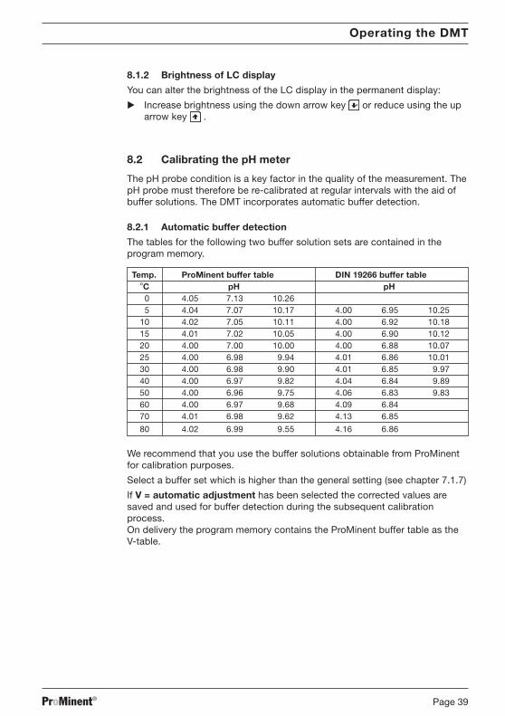
8.2.1 Automatic buffer detection
The tables for the following two buffer solution sets are contained in theprogram memory.
Temp. ProMinent buffer table DIN 19266 buffer table°C pH pH
0 4.05 7.13 10.265 4.04 7.07 10.17 4.00 6.95 10.25
10 4.02 7.05 10.11 4.00 6.92 10.1815 4.01 7.02 10.05 4.00 6.90 10.1220 4.00 7.00 10.00 4.00 6.88 10.0725 4.00 6.98 9.94 4.01 6.86 10.0130 4.00 6.98 9.90 4.01 6.85 9.9740 4.00 6.97 9.82 4.04 6.84 9.8950 4.00 6.96 9.75 4.06 6.83 9.8360 4.00 6.97 9.68 4.09 6.8470 4.01 6.98 9.62 4.13 6.85
80 4.02 6.99 9.55 4.16 6.86
We recommend that you use the buffer solutions obtainable from ProMinentfor calibration purposes.
Select a buffer set which is higher than the general setting (see chapter 7.1.7)
If V = automatic adjustment has been selected the corrected values aresaved and used for buffer detection during the subsequent calibrationprocess.On delivery the program memory contains the ProMinent buffer table as theV-table.
Operating the DMT
BA_DM_163_03_08_GB.p65 26.03.2008, 10:20 Uhr39
ProMinent®Page 40
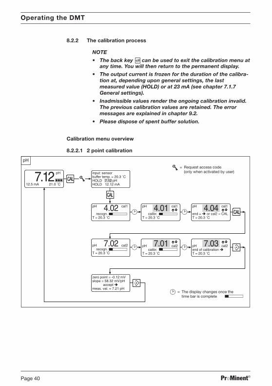
8.2.2 The calibration process
NOTE
• The back key can be used to exit the calibration menu atany time. You will then return to the permanent display.
• The output current is frozen for the duration of the calibra-tion at, depending upon general settings, the lastmeasured value (HOLD) or at 23 mA (see chapter 7.1.7General settings).
• Inadmissible values render the ongoing calibration invalid.The previous calibration values are retained. The errormessages are explained in chapter 9.2.
• Please dispose of spent buffer solution.
Calibration menu overview
8.2.2.1 2 point calibration
Operating the DMT
BA_DM_163_03_08_GB.p65 26.03.2008, 10:20 Uhr40

ProMinent® Page 41
8.2.2.2 1 point calibration
Proceed as follows to call up the calibration menu:
pH
7.12 input: manualbuffer temp. = 20.3 ˚CHOLD 7.12 pHHOLD 12.12 mA
input: sensorbuffer temp. = 20.3 ˚CHOLD 7.12 pHHOLD 12.12 mA
pH
12.5 mA 21.0 ˚C
or
Startingcalibration Press the CAL key when in the permanent display mode while the pH
probe is immersed in the liquid sample.
Under “input” set the detection method of the buffer temperature(correction value):Sensor (if the pH sensor incorporates a temperature gauge) ormanual (if using a separate temperature gauge).If you select manual, you must set the buffer temperatures under “buffertemp.” using the up and down arrow / keys.This setting is only valid during calibration.
You can change the pH HOLD value under “HOLD”. This setting is onlyvalid during calibration.
Remove the pH probe from the liquid sample, rinse and immerse in thefirst buffer solution.
Press the CAL key to start automatic buffer detection:
Operating the DMT
BA_DM_163_03_08_GB.p65 26.03.2008, 10:20 Uhr41

ProMinent®Page 42
pH
pH cal1
recogn.T = 20.3 ˚C
pH cal1
calibr.T = 20.3 ˚C
pH cal1
end = or cal2 = CALT = 20.3 ˚C
4.02 4.01 4.04
The progress of the buffer detection is indicated by a time bar. The calcu-lation of the calibration parameters begins automatically after the bufferdetection. This is also indicated by a time bar.
If you have selected sensor as the detection method for the buffer temper-ature, the current measured buffer temperature is displayed under “T”. If youhave selected manual, the manually entered buffer temperature is displayedunder “T”.The buffer value can be corrected during calibration using the / arrowkeys. If the sensor signal is unstable the time bar will wait until it becomesstable.
After completion of this calibration stage the display shows the nextmenu option for 1 point calibration:The buffer value can be corrected once again at this point using the arrowkeys / .
Progress from this point onwards depends upon whether you have selected a1 point calibration or a 2 point calibration (recommended!).
1 pointcalibration Press the enter key to end 1 point calibration.
The zero point is calibrated if the buffer value is between 5.5 pH and 8.0 pH.The slope is calibrated if the buffer value is less than 5.5 pH or greater than8.0 pH.
Proceed as for “conclude calibration”.
2 pointcalibration For a 2 point calibration remove the pH probe from the first buffer
solution, rinse and immerse in the second buffer solution.
Press the CAL key to restart automatic buffer detection.
Buffer detection and calibration take place as described above.
Operating the DMT
BA_DM_163_03_08_GB.p65 26.03.2008, 10:20 Uhr42

ProMinent® Page 43
After completion of this calibration stage the display shows the nextmenu option for 2 point calibration:The buffer value can be corrected once again at this point using the arrowkeys / .
Press the enter key to end 2 point calibration. Proceed as for “conclude calibration”.
Concludecalibration The calibration values (zero point and slope) are now displayed:
pH
zero point = -0.12 mVslope = 58.32 mV/pH acceptance meas. val. = 7.21 pH
The current pH value is shown under “meas. val.”.
Press the enter key to adopt the values or the back key to exitwithout saving the values.
The display changes to permanent display. The calibration is complete.
NOTE
Inadmissible values render the current calibration processinvalid. The previous calibration values are retained.The error messages during calibration are explained inchapter 9.2.
Operating the DMT
BA_DM_163_03_08_GB.p65 26.03.2008, 10:20 Uhr43

ProMinent®Page 44
9 Troubleshooting
9.1 Error messages during operation
The following error messages can appear in the permanent display duringoperation:
Message Displayed Cause of fault Remedyvalue
Output overflow Measured Warning: detected current value Change configuration ifvalue greater than pre-set necessary
20 mA value
Output underflow Measured Warning: detected current value Change configuration ifvalue less than pre-set necessary
4 mA value
pH input error ! -2.00 pH Probe not present or lead Check probe connectionor damaged (switch off probe check if16.00 pH necessary)
pH input error ! ~7.00 pH Short circuit Check probe connection(probe resistance ≅ 0 Ω)
defective pH probe !! Measured Measured probe Replace probe (switch offvalue resistance < 2 MΩ probe check if necessary)
ORP input error ! Measured value > 1200 mV or Check probe connection< -1200 mV,resp. fluctuating significantly
temp. input error ! 999.9 ° Probe not present or Check probe connectionlead damaged (set temperature measurement
to manual if necessary)
temp. input error ! -99.9 ° Short circuit Check probe connection(set temperature measurementto manual if necessary)
The error message disappears automatically once you have remedied thefault.
Troubleshooting
BA_DM_163_03_08_GB.p65 26.03.2008, 10:20 Uhr44
ProMinent® Page 45
Troubleshooting
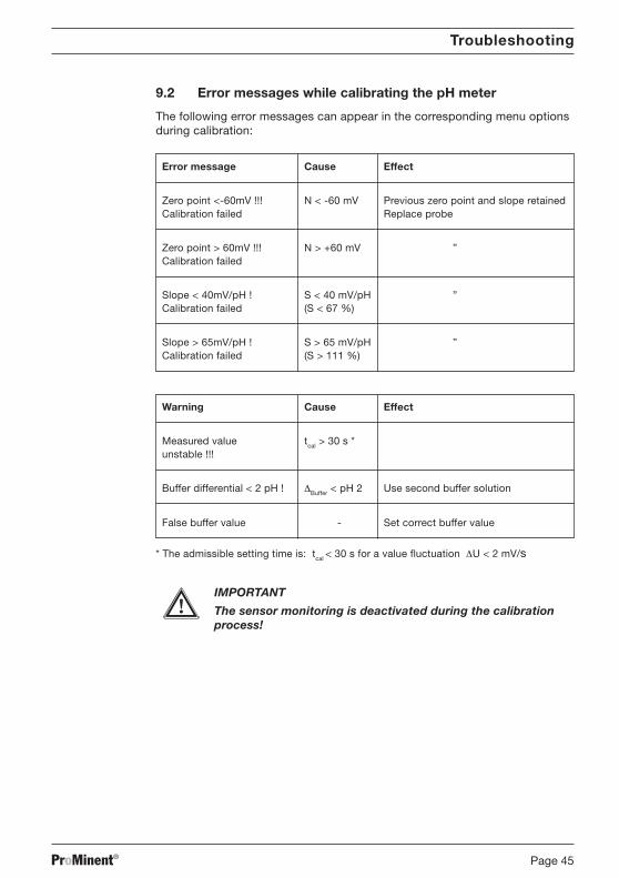
9.2 Error messages while calibrating the pH meter
The following error messages can appear in the corresponding menu optionsduring calibration:
Error message Cause Effect
Zero point <-60mV !!! N < -60 mV Previous zero point and slope retainedCalibration failed Replace probe
Zero point > 60mV !!! N > +60 mV ”Calibration failed
Slope < 40mV/pH ! S < 40 mV/pH ”Calibration failed (S < 67 %)
Slope > 65mV/pH ! S > 65 mV/pH ”Calibration failed (S > 111 %)
Warning Cause Effect
Measured value tcal > 30 s *unstable !!!
Buffer differential < 2 pH ! ∆Buffer < pH 2 Use second buffer solution
False buffer value - Set correct buffer value
* The admissible setting time is: tcal < 30 s for a value fluctuation ∆U < 2 mV/s
IMPORTANT
The sensor monitoring is deactivated during the calibrationprocess!
BA_DM_163_03_08_GB.p65 27.03.2008, 13:11 Uhr45

ProMinent®Page 46
10 Maintenance and repair
Maintenance The DMT requires no maintenance.
You should clean the housing with a damp, soapy cloth and then rub dry.
IMPORTANT
Solvents may attack the surfaces and must not be used.
Repair Please return the DMT to ProMinent Dosiertechnik GmbH for repair.
11 Disposal
IMPORTANT
Electronic waste is treated as special waste!
Observe current nationally and locally applicable directives.
Maintenance and repair / Disposal
BA_DM_163_03_08_GB.p65 26.03.2008, 10:20 Uhr46
ProMinent® Page 47
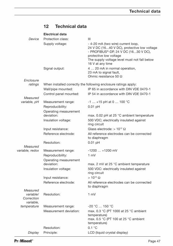
12 Technical data
Electrical dataDevice Protection class: III
Supply voltage: - 4-20 mA (two wire) current loop,24 V DC (16...40 V DC), protective low voltage- PROFIBUS®-DP, 24 V DC (16...30 V DC),protective low voltageThe supply voltage level must not fall below16 V at any time
Signal output: 4 … 20 mA in normal operation,23 mA to signal fault,Ohmic resistance 50 Ω
Enclosureratings When installed correctly the following enclosure ratings apply:
Wall/pipe mounted: IP 65 in accordance with DIN VDE 0470-1Control panel mounted: IP 54 in accordance with DIN VDE 0470-1
Measuredvariable, pH Measurement range: -1 … +15 pH at 0 … 100 °C
Reproducibility: 0.01 pHOperating measurementdeviation: max. 0.02 pH at 25 °C ambient temperatureInsulation voltage: 500 VDC; electrically insulated against
ring circuitInput resistance: Glass electrode: > 1012 ΩReference electrode: All reference electrodes can be connected
to diaphragmResolution: 0.01 pH
Measuredvariable, redox Measurement range: -1200 … +1200 mV
Reproducibility: 1 mVOperating measurementdeviation: max. 2 mV at 25 °C ambient temperatureInsulation voltage: 500 VDC: electrically insulated against
ring circuitInput resistance: > 1012 ΩReference electrode: All reference electrodes can be connected
to diaphragmMeasured
variable/ Resolution: 1 mVCorrection
variable,temperature Measurement range: -20 °C … 150 °C
Measurement deviation: max. 0.3 °C (PT 1000 at 25 °C ambienttemperature)max. 0.5 °C (PT 100 at 25 °C ambienttemperature)
Resolution: 0.1 °CDisplay Principle: LCD (liquid crystal display)
Technical data
BA_DM_163_03_08_GB.p65 26.03.2008, 10:20 Uhr47
ProMinent®Page 48
Technical data / Spare parts and accessories
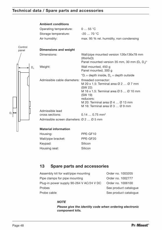
Ambient conditions
Operating temperature: 0 … 55 °C
Storage temperature: -20 … 70 °C
Air humidity: max. 95 % rel. humidity, non condensing
Dimensions and weight
Dimensions: Wall/pipe mounted version 126x136x78 mm(WxHxD)Panel mounted version 35 mm, 30 mm (Di, Do)*
Weight: Wall mounted, 450 gPanel mounted, 300 g
*Di = depth inside, Do = depth outside
Admissible cable diameters: threaded connector:M 20 x 1.5: Terminal area Ø 2 … Ø 7 mm(SW 22)M 16 x 1.5: Terminal area Ø 5 … Ø 10 mm(SW 19)reducers:M 20: Terminal area Ø 4 … Ø 13 mmM 16: Terminal area Ø 3 … Ø 9 mm
Admissible leadcross sections: 0.14 … 0.75 mm2
Admissible screen diameters: Ø 2 … Ø 5 mm
Material information
Housing: PPE-GF10
Wall/pipe bracket: PPE-GF20
Keypad: Silicon
Housing seal: Silicon
13 Spare parts and accessories
Assembly kit for wall/pipe mounting Order no. 1003205
Pipe clamps for pipe mounting Order no. 1002777
Plug-in power supply 90-264 V AC/24 V DC Order no. 1006100
Probes See product catalogue
Probe cable See product catalogue
NOTE
Please give the identity code when ordering electroniccomponent kits.
Do
Controlpanel
Di
BA_DM_163_03_08_GB.p65 27.03.2008, 13:11 Uhr48
ProMinent® Page 49
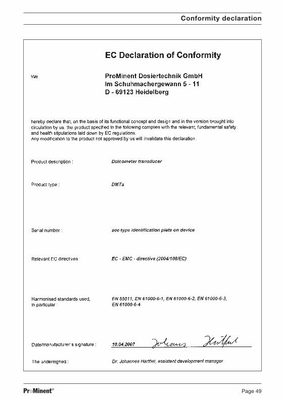
Conformity declaration
BA_DM_163_03_08_GB.p65 26.03.2008, 10:20 Uhr49
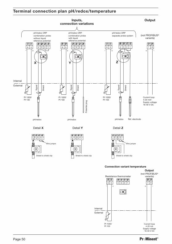
ProMinent®Page 50
External
pH/redox ORPcombination probe
pH/redox ORPseparate probe system
Pot
entia
l plu
g
pH/redox pH/redox pH/redox Ref. electrodeS
igna
l
Shi
eld
Sig
nal
Shi
eld
Sig
nal
Shi
eld
with liquidreference potential
5 56 6
connection variations
4 43 32 21 1 56 4 3 2 1
Pt 1000/Pt 100
+ +- - - +87
-+
X Y Z
Inputs, Output
ϑPt 1000/Pt 100
ϑPt 1000/Pt 100
ϑ
pH/redox ORPcombination probewithout liquidreference potential
(not PROFIBUS®
variants)
Internal
Current loop4-20 mA/Supply voltage16-40 V DC
Shield to shield clipShield to shield clip Shield to shield clip
3 334 442 1 2 1 2 1
Detail ZDetail YDetail X
Wire jumperWire jumper
Terminal connection plan pH/redox/temperature
(not PROFIBUS®
variants)
Current loop4-20 mA
Supply voltage16-40 V DC
External
Internal
56 4 3 2 1
Pt 1000/Pt 100
+-87
-+
Output
ϑ
Connection variant temperature
Resistance thermometer
BA_DM_163_03_08_GB.p65 26.03.2008, 10:20 Uhr50

ProMinent® Page 51
=~
2
1
=
3
4
5
6
+-
+-
+-
+-
+-
1 DMT transducer2 Controller3 Meter4 Recorder5 24 V DC (16...30 V DC/40 V DC) power supply unit6 4-20 mA current loop
IMPORTANT
• The signal inputs of all devices in the current loop must beelectrically isolated from the current output.
• Take into account the sum of the ohmic resistances of alldevices in the current loop (excluding power supply).
The input voltage of the transducer must never drop below16 V during operation.
The measured value will otherwise be wrong.
Wiring example - two wire system
BA_DM_163_03_08_GB.p65 26.03.2008, 10:20 Uhr51
ProMinent®Page 52
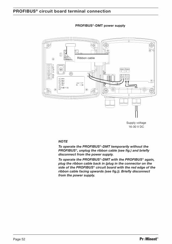
PROFIBUS®-DMT power supply
+ - + -Intern Extern
1 2 3 4
+ - + -
Supply voltage16-30 V DC
NOTE
To operate the PROFIBUS®-DMT temporarily without thePROFIBUS®, unplug the ribbon cable (see fig.) and brieflydisconnect from the power supply.
To operate the PROFIBUS®-DMT with the PROFIBUS® again,plug the ribbon cable back in (plug in the connector on theside of the PROFIBUS® circuit board with the red edge of theribbon cable facing upwards (see fig.)). Briefly disconnectfrom the power supply.
PROFIBUS® circuit board terminal connection
Ribbon cable
BA_DM_163_03_08_GB.p65 26.03.2008, 10:20 Uhr52

ProMinent® Page 53
Index
A
Access code 32
B
Buffer detection 39, 41General settings 31
C
Calibrationfault messages 44pH meter 39Pt 100 28
Calibration menu 40menu overview 40
Conformity declaration 48Control elements 17Check ORP probe 25
D
Device type 31
F
Fault messageduring operation 43during calibration 44
G
General settings 31changing 31
I
Identity codemeasured variable pH 5measured variable redox 6measured variable temperature 7
Info display 20, 21Installation 13
K
Key functions 19
L
Languagegeneral settings 31
LC displaybrightness 39
M
Menu option 21Menu overview
calibration menu 40measured variable pH 23measured variable redox 24measured variable temperature 33tabular 22
Mounting 10
O
Operating 38Operating menu 20
schematic 19Output
General settings 31, 32, 36parameters 28, 34
P
Parametersoutput 28, 34measurement 25temperature 26, 34
Permanent display 38Probe check (pH) 25Probe condition (pH) 38Probe type (temperature)
general settings 36PROFIBUS® 16, 50
S
Settings 22Slope 25, 42
T
Temperature measurementparameters 26, 34
Temperature gaugegeneral settings 31, 32, 36
Terminal connection plan 49Troubleshooting 43
2-wire system 51Typical wiring for a 2-wire system 51
Z
Zero point 25, 42
BA_DM_163_03_08_GB.p65 26.03.2008, 10:20 Uhr53

ProMinent®Page 54
BA_DM_163_03_08_GB.p65 26.03.2008, 10:20 Uhr54

Drilling template for DMT
Page 55ProMinent®
4 x 3.5 mm diam. holes
3460-4.1
108
100
5
100
60
R 4
ATTENTION: Photocopying the template can change the scale!
3460-4.1
ProMinent®
Addresses and delivery informationfrom the manufacturer:
ProMinent Dosiertechnik GmbHIm Schuhmachergewann 5-1169123 HeidelbergGermany
Telephone: +49 6221 842-0Fax: +49 6221 842-419
BA_DM_163_03_08_GB.p65 10.04.2008, 8:44 Uhr56