Embed Size (px)
Citation preview
1/36
VS-pumps Manual Rev 3.docx Subject to change without prior notice.
OPERATING INSTRUCTIONS
CENTRIFUGAL PUMPS WITH INTEGRATED FREQUENCY DRIVE
VS-SERIES
2/36
VS-pumps Manual Rev 3.docx Subject to change without prior notice.
Contents 1. General ...............................................................................................................................................................4
1.1 Symbols ........................................................................................................................................................4
1.2 Fields of applications ..................................................................................................................................4
1.2.1 AE_-, L_-, AL_- pumps........................................................................................................................4
1.2.2 AEP-, LP-, ALP- pumps ......................................................................................................................4
1.2.3 LH-, ALH- pumps .................................................................................................................................4
1.2.4 LS-, ALS- pumps ..................................................................................................................................4
1.3 Limits of application and use .....................................................................................................................5
1.4 Manufacturer ................................................................................................................................................5
1.5 Version ..........................................................................................................................................................5
2. Handling, transport and storage of the pump ................................................................................................5
3. Design and function ..........................................................................................................................................6
3.1 Construction .................................................................................................................................................6
3.2 Technical data .............................................................................................................................................6
3.3 Pump identification ......................................................................................................................................8
4. Safety ..................................................................................................................................................................9
4.1 Safety instructions .......................................................................................................................................9
4.2 Training .........................................................................................................................................................9
4.3 Elements of danger if safety regulations are not obeyed ......................................................................9
4.4 Safety instructions for inspection and assembly ................................................................................. 10
4.5 Operating the pump ................................................................................................................................. 10
5. Installation, introduction and start-up .......................................................................................................... 10
5.1 Positions for installation .......................................................................................................................... 11
5.2 Electrical connections .............................................................................................................................. 11
5.3 Control methods and connections ......................................................................................................... 12
5.3.1 I/O’s and Kolmeks Factory Defaults of the VS-pump (inputs and outputs) ............................. 12
5.3.2 VS-pump monitoring parameters ................................................................................................... 14
5.3.3 VSA-pump – speed reference from the display ........................................................................... 15
5.3.4 VSB-pump – constant pressure between the pump flanges ...................................................... 15
5.3.5 VSC-pump - constant pressure in between inlet- and outlet-line .............................................. 16
5.3.6 VSD-pump - constant pressure in discharge (pressure boosting) ............................................ 17

3/36
VS-pumps Manual Rev 3.docx Subject to change without prior notice.
5.3.7 VSF-pump - constant temperature ................................................................................................. 17
5.3.8 VSG-pump - controlled by external system .................................................................................. 18
5.3.9 VSM-pump – controlled by MODBUS RTU –bus connection .................................................... 18
6. Service, spare parts and troubleshooting ................................................................................................... 19
6.1 Shaft seals ................................................................................................................................................. 19
6.2 Other parts ................................................................................................................................................ 20
6.3 Troubleshooting ........................................................................................................................................ 21
6.4 Checking of alarm history ....................................................................................................................... 25
6.5 Alarm and fault codes .............................................................................................................................. 25
7. Declaration of Conformity .............................................................................................................................. 29
8. Annex ............................................................................................................................................................... 30
8.1 Wiring diagram VSA-single pump .......................................................................................................... 30
8.2 Wiring diagram VSB-single pump .......................................................................................................... 31
8.3 Wiring diagram VSC-single pump ......................................................................................................... 32
8.4 Wiring diagram VSD-single pump ......................................................................................................... 33
8.5 Wiring diagram VSF-single pump .......................................................................................................... 34
8.6 Wiring diagram VSG-single pump ......................................................................................................... 35
8.7 Wiring diagram VSM-single pump ......................................................................................................... 36
4/36
VS-pumps Manual Rev 3.docx Subject to change without prior notice.
1. General
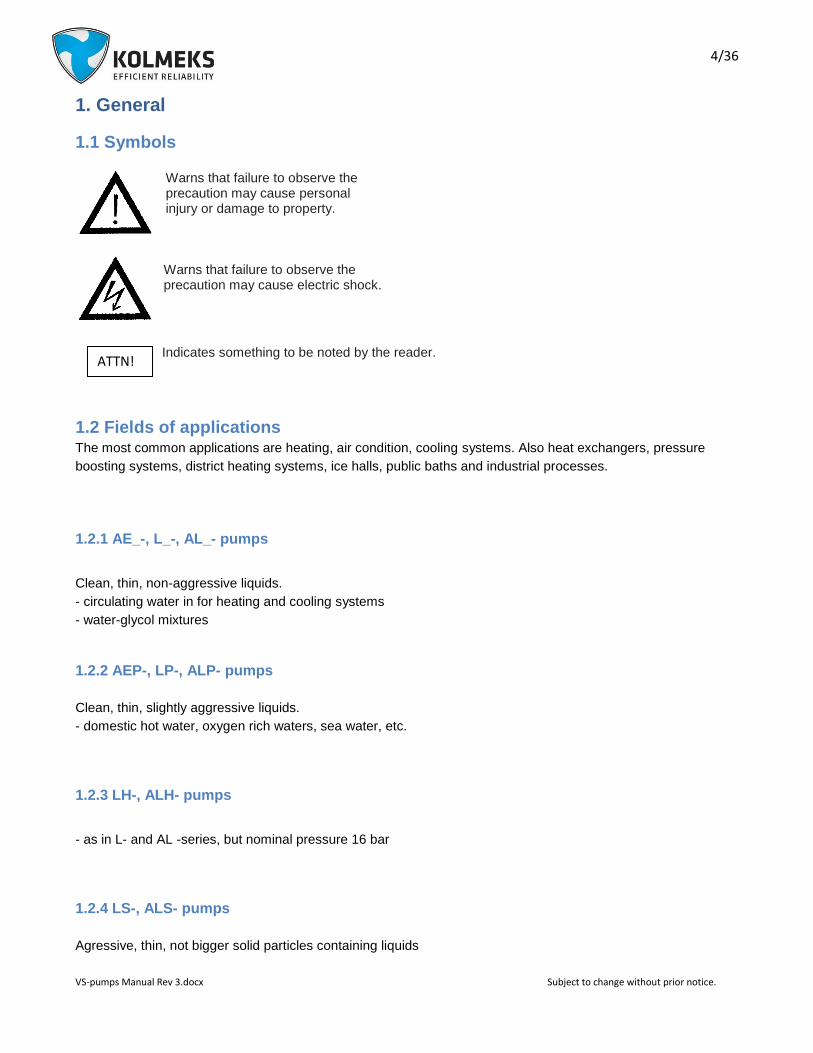
1.1 Symbols
Warns that failure to observe the precaution may cause personal injury or damage to property. Warns that failure to observe the precaution may cause electric shock.
Indicates something to be noted by the reader.
1.2 Fields of applications The most common applications are heating, air condition, cooling systems. Also heat exchangers, pressure
boosting systems, district heating systems, ice halls, public baths and industrial processes.
1.2.1 AE_-, L_-, AL_- pumps
Clean, thin, non-aggressive liquids.
- circulating water in for heating and cooling systems
- water-glycol mixtures
1.2.2 AEP-, LP-, ALP- pumps
Clean, thin, slightly aggressive liquids.
- domestic hot water, oxygen rich waters, sea water, etc.
1.2.3 LH-, ALH- pumps
- as in L- and AL -series, but nominal pressure 16 bar
1.2.4 LS-, ALS- pumps
Agressive, thin, not bigger solid particles containing liquids
ATTN!

5/36
VS-pumps Manual Rev 3.docx Subject to change without prior notice.
- in addition to above mentioned liquids various acids, salts, oxidizing and chemically active organic fluids
1.3 Limits of application and use
Nominal pressure: AE-, AEP-, L-, AL-, ALP- pumps: 10 bar
LH-, ALH-, LS- and ALS-pumps: 16 bar
Medium temperature range: -10 ... + 90 °C
Ambient temperature: 0 ... +40°C (diurnal average max. +35°C)
Suitability of materials and seals for pumped liquid shall be always checked between purchaser
and supplier. The nominal pressure and the max. temperature of pumped liquid are stamped on
the pump rating plate. Never use the pump in any other application or conditions without
manufacturer’s acceptance. In the case of damage there may be danger to persons by having
poisoning, burns, wounds etc. depending on the pumped liquid and it’s temperature and pressure. The
pump surface temperature may cause danger depending on the working conditions.
1.4 Manufacturer
This product is manufactured by KOLMEKS OY, P.O.BOX 27, FIN-14201 TURENKI, FINLAND.
1.5 Version Release date of this manual is 23.02.2015. This is version no. 0.
2. Handling, transport and storage of the pump
Normally the pumps are stable when they are transported and don’t go down even they are bent 10°. Pumps
shall be stored in a dry and cool place protected from dust. Temperature of environment must be in -10 °C ...
+50°C. It is not allowed to lift the pump from frequency converter. In the case of longer storage time or the
pump serves as a stand-by, it is recommended to rotate the pump manually eg. from the motor fan at least
once a month.
ATTN
!
ATTN!

6/36
VS-pumps Manual Rev 3.docx Subject to change without prior notice.
3. Design and function
3.1 Construction The pump and motor constitute a unit, where the rotating parts of both the pump and the motor are on the same
shaft (mono-block design). The motor is of a dry type and the frequency converter is integrated to the electric
motor.
Electric motor: Totally enclosed, fan cooled A.C. motor, with frequency converter.
Protection form: IP54
Insulating class: F
3.2 Technical data
Pump Connection Hz Nominal power
Supply current A Weight
type
max P2n kW 1 x 230 V kg
AE_/AEP-26/2VS 1" 50 0,65 3,0 20
AE_/AEP-33/2VS 1 1/4" 65 1,1 4,0 27
AE_/AEP-33/2VS 1 1/4" 50 1,5 4,0 38
L_-32A/2VS DN32 50 0,65 3,0 27
L_-32A/2VS DN32 60 1,1 4,0 30
L_-40A/2VS DN40 50 1,1 4,0 32
L_-40A/2VS DN40 50 1,5 4,0 43
L_/LP-50A/4VS DN50 55 0,55 2,2 42
L_/LP -50A/4VS DN50 63 0,9 3,0 42
L_/LP -50B/2VS DN50 50 1,1 4,0 36
L_/LP -50D/2VS DN50 50 2,2 7,3 49
L_/LP -50D/2VS DN50 50 3,0 9,6 55
L_-65A/4VS DN65 50 0,55 2,2 48
L-65A/4VS DN65 60 0,9 3,0 48
L_-65A/4VS DN65 60 1,5 4,0 57
L_-65A/4VS DN65 65 3,0 9,6 64
L_-65B/2VS DN65 50 3,0 9,6 64
L_-65B/2VS DN65 50 4,0 11,5 72
L_-65B/2VS DN65 50 5,5 14,2 96
L_-65B/2VS DN65 50 7,5 20,0 104
Noise level of all pump types is under 70 dB (A, 1 m). Weight is without transmitter.

7/36
VS-pumps Manual Rev 3.docx Subject to change without prior notice.
Pump Connection Hz Nominal power
Supply current A Weight
type
max P2n kW 1 x 230 V kg
L_-80A/4VS DN80 50 0,75 3,0 52
L_-80A/4VS DN80 50 1,5 4,0 60
L_-80A/4VS DN80 63 3,0 9,6 66
L_-80A/2VS DN80 50 4,0 11,5 73
L_-80A/2VS DN80 50 5,5 14,2 97
L_-80A/2VS DN80 50 7,5 20,0 105
L_-100S/4VS DN100 50 4,0 11,5 175
L_-100S/4VS DN100 50 5,5 14,2 185
L_-100S/4VS DN100 50 7,5 20,0 210
AL_/ALP-1102/4VS DN100 50 0,75 3,0 66
AL_/ALP-1102/4VS DN100 50 1,5 4,0 69
AL_/ALP-1102/4VS DN100 60 3,0 9,6 75
AL_/ALP-1102/2VS DN100 50 5,5 14,2 107
AL_/ALP-1102/2VS DN100 50 7,5 20,0 114
AL_-1129/4VS DN125 50 4,0 11,5 174
AL_-1129/4VS DN125 50 5,5 14,2 181
AL_-1129/4VS DN125 50 7,5 20,0 208
AL_-1154/4VS DN150 50 7,5 20,0 221

8/36
VS-pumps Manual Rev 3.docx Subject to change without prior notice.
3.3 Pump identification
AL - 110 2 / 4 VS B
L P - 50 A / 4 VS C
Pump series:AE-, L-, AL- Material of pump housing, sealing flange and impeller: no letter = grey cast iron EN-GJL-200 / 10 bar H = nodular cast iron EN-GJS-400 / 16 bar P = bronze CuSn10 / 10 bar S = stainless steel AISI 316 / 16 bar
Flange size, DN-size:
20 = 3/4”
25 = 1”
32 = DN 32
40 = DN 40
50 = DN 50
65 = DN 65
80 = DN 80
110 = DN 100
112 = DN125
115 = DN150
Poles of the electric motor:
2 = rotation speed 50 r/s (50 Hz)
rotation speed 60 r/s (60 Hz)
4 = rotation speed 25 r/s (50 Hz)
rotation speed 30 r/s (60 Hz)
rotation speed 31.5 r/s (63 Hz)
rotation speed 32.5 r/s (65 Hz)
VS = VS - the frequency converter is integrated
to the pump:
VSA, VSB, VSC, VSD, VSF, VSG, VSM (check 5.3
Control methods and connections)
(5/10) => VSB ja VSC: 5 = measure range of
differential pressure [bar], 10 = measure range of
pressure transmitter [bar]
Pump type Motor code Impeller size Electrical power at duty point Duty point, Max. medium temperature
Motor type Nominal voltage and current
Rotating speed range, isolating and enclosure
glass
Serial number, Nominal pressure
Different material of impeller:
PM = Bronze CuSn10
SS = Stainless steel AISI316
Markins for accessories:
T = external mechanical seal for aggressive medium
H = flush for mechanical seal
KT = double mechanical seal
Sn = different mechanical seal
Kn = different surface treatment
Phases, frequency and duty
typetötapa Nominal shaft power
Bearing types, CE -marking Manufacturer, country of origin

9/36
VS-pumps Manual Rev 3.docx Subject to change without prior notice.
4. Safety This manual includes important information concerning installation and operating the pump. Persons
who are involved in installation or/and operation of the pump, should read and understand these
instructions before installation or starting the pump.
There are live parts inside the frequency converter of the VS -pump, when the supply voltage is connected.
Incorrect installation of VS –pump may cause damage to the pump or bodily injuries, even death. Touching the
live parts may be mortal even the supply voltage is disconnected. Obey instructions of this
manual and national and local requirements and standards.
Wait at least 4 minutes!
- installation must be protected by fuses and insulated correctly.
- covers and cable inlets must be installed.
It is user’s or certified electrician’s responsibility to ensure the correct earthing and protection in accordance
with applicable national and local requirements and standards.
4.1 Safety instructions
1. VS-pump must be disconnected from the mains if repair work is to be carried out. Check that the mains supply
has been disconnected and necessary time has passed (at least 10 minutes).
2. The device must be connected correctly to the earth. User must be protected from supply voltage and the
pump must be protected from short circuit according to the national and local requirements and standards. The
overload protection is included in VS -pump.
3. Earth leakage is more than 3,5 mA. It means, that installation of supply cable must be fixed.
4.2 Training
The persons who have responsibility for installing or/and operating the pump, should be trained.
4.3 Elements of danger if safety regulations are not obeyed
ATTN!

10/36
VS-pumps Manual Rev 3.docx Subject to change without prior notice.
If the safety regulations are not obeyed, personal injuries or damage to the pump or related devices may occur.
Valid safety instructions must be obeyed.
4.4 Safety instructions for inspection and assembly
it is user’s responsibility to ensure that persons who carry out inspections and installations are qualified experts
and familiarized themselves with these instructions carefully.
4.5 Operating the pump
Working safety of the delivered pump and related devices can be ensured only if these devices are operated
according to the section 1.2 Fields of application and 1.3 Limits of application and use of this manual.
5. Installation, introduction and start-up
The pump can be installed to the piping without separate supporting.
The position of the motor unit with the frequency converter can be changed by removing the motor unit from the
pump housing and setting it to the desired position with certain limitations.
When installing the pump pay attention to the following:
- space enough for service and inspection of the pump
- free visibility to the display of the potentiometer
- free visibility to the rating plate of the pump.
- possibility to use lifting mechanism if needed
- shut-off valves on the both sides of the pump
- the frequency converter is not too close hot pipes.
11/36
VS-pumps Manual Rev 3.docx Subject to change without prior notice.
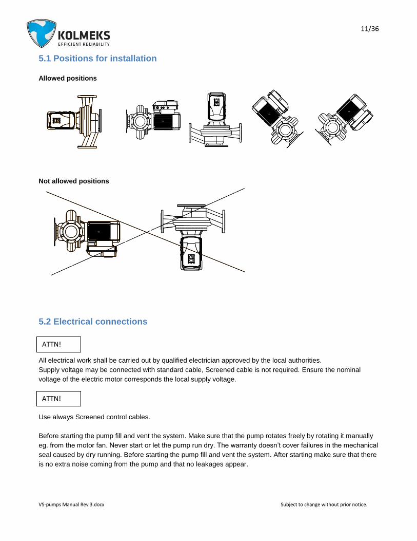
5.1 Positions for installation
Allowed positions
Not allowed positions
5.2 Electrical connections
All electrical work shall be carried out by qualified electrician approved by the local authorities.
Supply voltage may be connected with standard cable, Screened cable is not required. Ensure the nominal
voltage of the electric motor corresponds the local supply voltage.
Use always Screened control cables.
Before starting the pump fill and vent the system. Make sure that the pump rotates freely by rotating it manually
eg. from the motor fan. Never start or let the pump run dry. The warranty doesn’t cover failures in the mechanical
seal caused by dry running. Before starting the pump fill and vent the system. After starting make sure that there
is no extra noise coming from the pump and that no leakages appear.
ATTN!
ATTN!

12/36
VS-pumps Manual Rev 3.docx Subject to change without prior notice.
5.3 Control methods and connections
5.3.1 I/O’s and Kolmeks Factory Defaults of the VS-pump (inputs and outputs)
Terminal Signal Kolmeks Factory Defaul
A RS485 Serial -
B RS485 Serial +
1 +10Vref +10 V reference voltage
2 AI1+ Analogue input 1 voltage or
current
A-, B- and C-versions: Current (SW 2 + P3.1) D- and G-versions: Voltage (SW2 + P.3.1)
3 AI1-/GND
AI1-
6b
6 24Vout +24 V, loadability 100mA -------------
7 DIN COM
Digital input common
8 DI1 Digital input 1 Run / Stop (P4.1 - P4.18) *
9 DI2 Digital input 2 PID-Controller (P4.1 - P4.18) *
10 DI3 Digital input 3 Preset speed, 40 Hz (P4.1 - P4.18) *
4 AI2+ Analogue input 2 voltage or
current Current (SW 3 + P3.5)
5 AI2-/GND
AI2-
13 DO1- Digital output -
14 DI4 Digital input 4 Not in use(P4.1 - P4.18) *
15 DI5 Digital input 5 Fault reset (P4.1 - P4.18) *
16 DI6 Digital input 6 NC External fault (P4.1 - P4.18) *
18 AO1+ Analogue output Output Frequency 0 - fmax , 0 - 10V (P6.1)
20 DO1+ Digital output + Not in use
*) Parameter group 4 operations are activated by choosing digital inputs with parameters 4.1 - 4.18
22 RO1/2
Run 23 RO1/3
24 RO2/1
Fault 25 RO2/2
26 RO2/3
13/36
VS-pumps Manual Rev 3.docx Subject to change without prior notice.
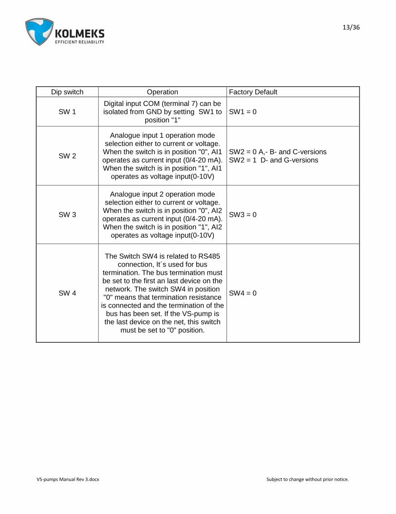
Dip switch Operation Factory Default
SW 1 Digital input COM (terminal 7) can be isolated from GND by setting SW1 to
position "1" SW1 = 0
SW 2
Analogue input 1 operation mode selection either to current or voltage. When the switch is in position "0", AI1 operates as current input (0/4-20 mA). When the switch is in position "1", AI1
operates as voltage input(0-10V)
SW2 = 0 A,- B- and C-versions SW2 = 1 D- and G-versions
SW 3
Analogue input 2 operation mode selection either to current or voltage. When the switch is in position "0", AI2 operates as current input (0/4-20 mA). When the switch is in position "1", AI2
operates as voltage input(0-10V)
SW3 = 0
SW 4
The Switch SW4 is related to RS485 connection, It´s used for bus
termination. The bus termination must be set to the first an last device on the network. The switch SW4 in position "0" means that termination resistance
is connected and the termination of the bus has been set. If the VS-pump is the last device on the net, this switch
must be set to "0" position.
SW4 = 0

14/36
VS-pumps Manual Rev 3.docx Subject to change without prior notice.
5.3.2 VS-pump monitoring parameters
While VS-pump is running following frequency converter actual values can be seen from frequency converter
‘M’-menu.
Monitoring parameters ('M'-menu):
Code Monitoring value Unit ID Description
V1.1 Output frequency Hz 1 Output frequency to motor
V1.2 Frequency reference Hz 25 Frequency reference to motor control
V1.3 Motor shaft speed rpm 2 Motor speed in rpm
V1.4 Motor Current A 3
V1.5 Motor Torque % 4 Calculated shaft torque
V1.6 Motor Power % 5 Total power consumption of AC drive
V1.7 Motor Voltage V 6
V1.8 Motor temperature % 9 Calculated motor temperature
V1.9 DC-link Voltage V 7
V1.10 Unit temperature °C 8 Heatsink temperature
V1.11 Board temperature °C 1825 Power board temperature
V1.12 Analogue input 1 % 13 Analogue input AI1
V1.13 Analogue input 2 % 14 Analogue input AI2
V1.14 Exp. Analogue input % 1837 Analogue input on OPTB4
V1.15 Analogue output % 26 Analogue output
V1.16 Exp. Analogue out 1 % 1838 Analogue output 1 on OPTB4-BF
V1.17 Exp. Analogue out 2 % 1839 Analogue output 2 on OPTB4
V1.18 DI1, DI2, DI3 15 Digital inputs status
V1.19 DI4, DI5, DI6 16 Digital inputs status
V1.20 DI7, DI8, DI9 1835 Digital inputs on OPTB1 status
V1.21 DI10, DI11, DI12 1836 Digital inputs on OPTB1 status
V1.21 RO1, RO2, DO 17 Digital outputs status
V1.23 EO1, EO2, EO3, EO4 1852 Expansion board digital outputs status
V1.24 Process variable 29 Scaled process variable. See P7.10
V1.25 PID setpoint % 20 PID controller setpoint
V1.26 PID error value % 22 PID controller error
V1.27 PID feedback % 21 PID controller actual value
V1.28 PID output % 23 PID controller output
V1.29 Temperature sensor 1 °C or °K 1860 OPTBH sensor 1
V1.30 Temperature sensor 2 °C or °K 1861 OPTBH sensor 2
V1.31 Temperature sensor 3 °C or °K 1862 OPTBH sensor 3
V1.32 ASi board state 1894 OPTBK state
NOTE! All monitoring parameters may not be visible, if option board isn´t connected or
PID-controller is disactivated (Digital input 2)

15/36
VS-pumps Manual Rev 3.docx Subject to change without prior notice.
5.3.3 VSA-pump – speed reference from the display
Applications
Systems, where the duty point remains constant and where is no need for continuous automated regulation.
Accessories
Pump and frequency converter.
Operation principle
The speed of electric motor can be adjusted manually at the site during commissioning of the pump. The pump
will run with constant speed. The required speed is selected by pushing button BACK/RESET-button until can be
selected either ’R’, ’M’, ’P’ or ’S’. From these is selected ’R’ (=Reference) and pressed ’OK’. Frequency
reference is selected with Arrow-buttons and confirmed by pushing ‘OK’ –button. While pump is running,
frequency converter actual values can be researched from ‘M’-menu (=Monitoring)
Pump curve
QH-curve of the pump is equal with that of single speed pump.
Standard control connections (see ANNEX 8.1 VSA-wiring diagram)
5.3.4 VSB-pump – constant pressure between the pump flanges
Applications
Systems, where are variations in the flow and where pressure losses are generated mainly on the consumption
equipment. Heating circulation, where the pressure loss on the heat equipment is small.
Accessories
Pump, frequency converter, 2 pcs of pressure transmitters installed to the pump flanges.
Operation principle and flow adjustment
The level of the constant pressure difference between the pump flanges can be adjusted by the controller of
frequency converter (parameter P.12.2). By pushing button BACK/RESET-button until can be selected either ’R’,
’M’, ’P’ or ’S’. From these is selected ’P’ (=Parameters) and pressed ’OK’. With Arrow-buttons is searched
parameter P.12.2. By pushing ‘OK’ –button, appears value of the parameter P12.2 to the display which is
reference for PI –controller (constant differential pressure). The required reference value can be adjusted by the
Up- and Down-arrow buttons. It is saved by pushing ‘OK’ –button. Value is percents of max. measuring value.
For Example when using 10 bar Pressure Transmitters the Pressure Difference 5 bars = 100 %. With 6 bar
Transmitters the difference 3 bars = 100% and so on. After the set point is saved, by pushing button
BACK/RESET-button twice, starting situation is achieved. While pump is running, frequency converter actual
values can be researched from ‘M’-menu (=Monitoring)

16/36
VS-pumps Manual Rev 3.docx Subject to change without prior notice.
Pump curve
QH-curve of the pump is controlled to a horizontal line, which is suitable for systems with low pressure loss
share in heat exchanger compared to the total pressure loss.
Standard control connections (see ANNEX 8.2 VSB-wiring diagram)
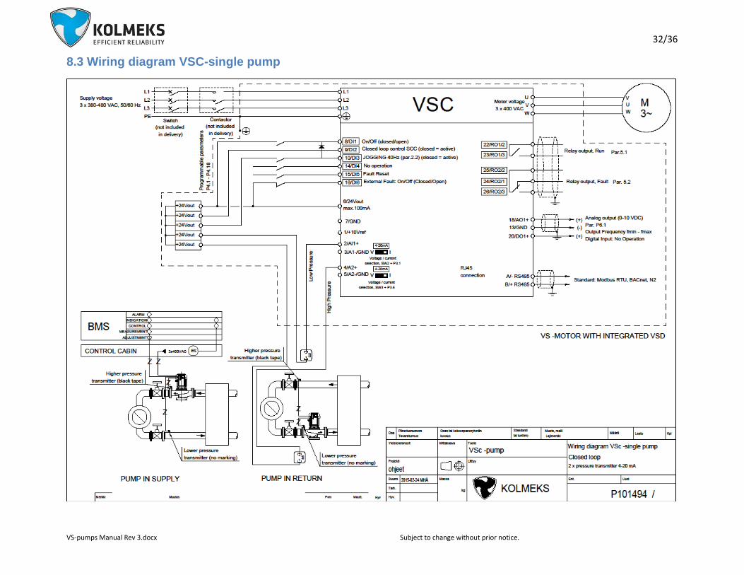
5.3.5 VSC-pump - constant pressure in between inlet- and outlet-line
Applications
Systems, where are variations in the flow and where pressure losses are generated mainly on the source of heat
equipment. Heating and cooling circulations and the pressure boosting of parellel circulations.
Accessories
Pump, frequency converter and 2 pcs of pressure transmitters. Another transmitter to be installed to the suction
or pressure flange of the pump and another one on to the system inlet or outlet pipe.
Operation principle and flow adjustment
The level of the constant pressure difference between the inlet and outlet line can be adjusted by the controller
of frequency converter (parameter P.12.2). By pushing button BACK/RESET-button until can be selected either
’R’, ’M’, ’P’ or ’S’. From these is selected ’P’ (=Parameters) and pressed ’OK’. With Arrow-buttons is searched
parameter P.12.2. By pushing ‘OK’ –button, appears value of the parameter P12.2 to the display which is
reference for PI –controller (constant differential pressure). The required reference value can be adjusted by the
Up- and Down-arrow buttons. It is saved by pushing ‘OK’ –button. Value is percents of max. measuring value.
For Example when using 10 bar Pressure Transmitters the Pressure Difference 5 bars = 100 %. With 6 bar
Transmitters the difference 3 bars = 100% and so on. After the set point is saved, by pushing button
BACK/RESET-button twice, starting situation is achieved. While pump is running, frequency converter actual
values can be researched from ‘M’-menu (=Monitoring)
Pump curve
QH-curve of the pump is controlled to a quadratic. The relation of pressure loss in the source of heat (cold) to the
loss in the system defines the shape of the curve. When the losses in the heat exchanger are large part of the
whole losses in the system the curve is more steep.
Standard control connections (see ANNEX 8.3 VSC-wiring diagram)
17/36
VS-pumps Manual Rev 3.docx Subject to change without prior notice.
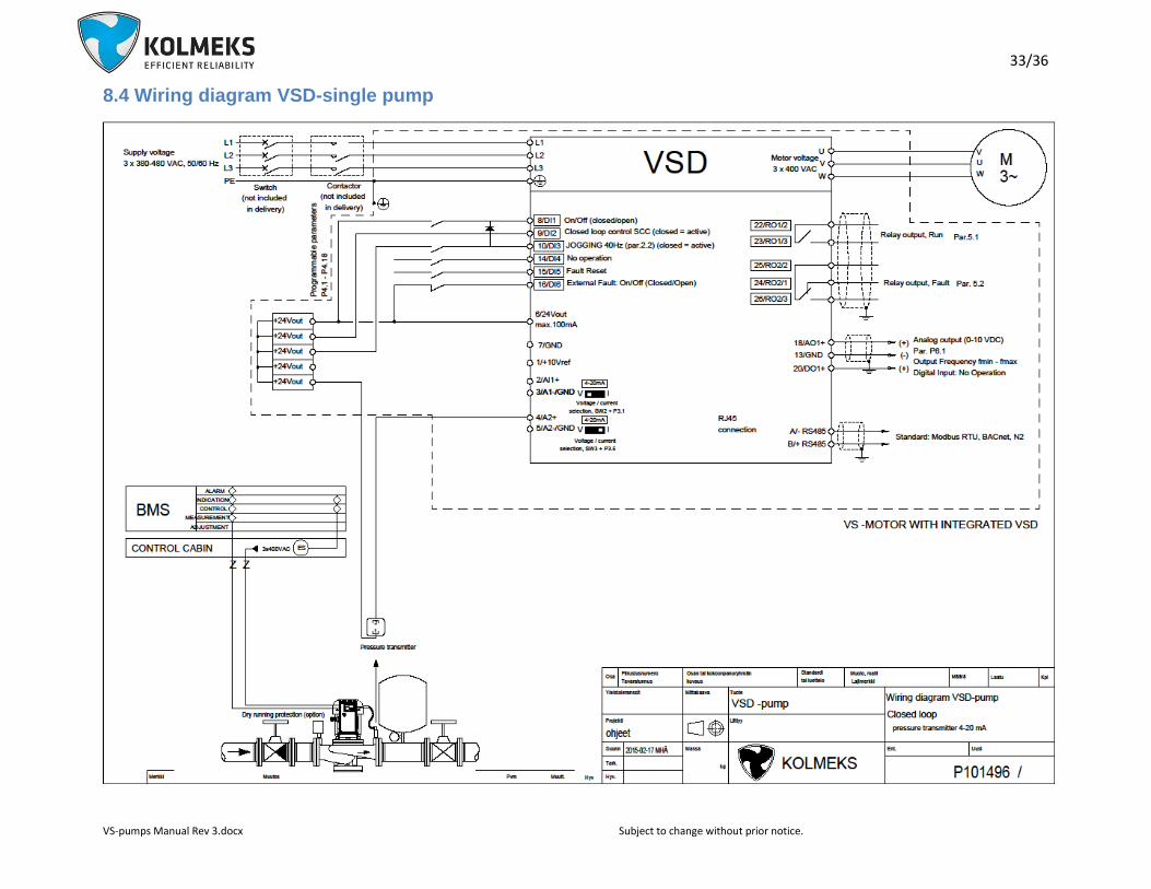
5.3.6 VSD-pump - constant pressure in discharge (pressure boosting)
Applications
Pressure boosting or other open systems, where constant pressure is required.
Accessories
Pump, frequency converter and pressure transmitter. The pressure transmitter is installed
to the pressure flange of the pump or near to the consumption in the pipe line.
Operation principle
The level of the constant pressure in discharge can be adjusted by the controller of frequency converter
(parameter P.12.2). By pushing button BACK/RESET-button until can be selected either ’R’, ’M’, ’P’ or ’S’. From
these is selected ’P’ (=Parameters) and pressed ’OK’. With Arrow-buttons is searched parameter P.12.2. By
pushing ‘OK’ –button, appears value of the parameter P12.2 to the display which is reference for PI –controller
(constant pressure). The required reference value can be adjusted by the Up- and Down-arrow buttons. It is
saved by pushing ‘OK’ –button. Value is percents of max. measuring value (mentioned in transducer). After the
set point is saved, by pushing button BACK/RESET-button twice, starting situation is achieved. While pump is
running, frequency converter actual values can be researched from ‘M’-menu (=Monitoring)
Standard control connections (see ANNEX 8.6 VSD-wiring diagram)
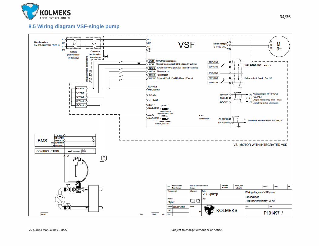
5.3.7 VSF-pump - constant temperature
Applications
Heating and cooling systems, where the constant temperature is required by adjusting the flow.
Accessories
Pump, frequency converter and temperature transmitter (and sensor).
Operation principle
The level of the constant temperature can be adjusted by the controller of frequency converter (parameter
P.12.2). By pushing button BACK/RESET-button until can be selected either ’R’, ’M’, ’P’ or ’S’. From these is
selected ’P’ (=Parameters) and pressed ’OK’. With Arrow-buttons is searched parameter P.12.2. By pushing
‘OK’ –button, appears value of the parameter P12.2 to the display which is reference for PI –controller (constant
temperature). The required reference value can be adjusted by the Up- and Down-arrow buttons. It is saved by
pushing ‘OK’ –button. Value is percents of max. measuring value (mentioned in transducer). After the set point
is saved, by pushing button BACK/RESET-button twice, starting situation is achieved. While pump is running,
frequency converter actual values can be researched from ‘M’-menu (=Monitoring)
ATTENTION! When ordering the pump, the response of the control must be informed. In the heating system the
response is normal, in the cooling system inverse. Normal, the pumping goes down, when the temperature
(feedback) goes up, inverse, the pumping goes up, when the temperature (feedback) goes up (par. P.12.10 =>
normal = 0, inverse = 1).
Standard control connections (see ANNEX 8.7 VSF-wiring diagram)
18/36
VS-pumps Manual Rev 3.docx Subject to change without prior notice.
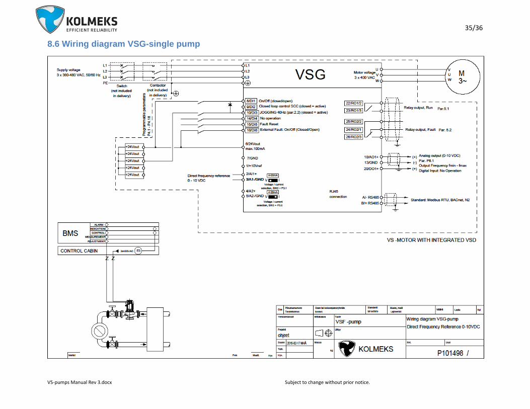
5.3.8 VSG-pump - controlled by external system
Applications
Systems, where are variations in the flow and/or where the flow is controlled mainly with the pump. The pump is
controlled by an external system or controller.
Accessories
Pump and frequency converter.
Operation principle
The speed reference for pumps is given to Analogue input 1 (0-10 V) from external control system, external
controller, process control, etc
ATTENTION!! If the external control system is not in use when pumping is neededFrequency reference source
must be changed; Parameter P.1.12 is changed 0 4. After the change Frequency reference is set as in 5.3.3
VSA-pump – speed reference from the display.
Standard control connections (see ANNEX 8.8 VSG-wiring diagram - with external controller in use)
5.3.9 VSM-pump – controlled by MODBUS RTU –bus connection
Applications
Systems, where are variations in the flow and/or where the flow is controlled mainly with the pump. The pump is
controlled by an external system or controller.
.
Accessories
Pump and frequency converter.
Operation principle
All control, adjusting and indications are taken care with MODBUS RTU –bus connections.
Standard control connections (see ANNEX 8.9 VSM-wiring diagram - MODBUS RTU –bus connection)
5.3.10 Local Control Panel
The VS -pump optionally features a separate cable connected Local Control Panel, which makes up the
complete interface for operation and monitoring of the VS -pump. If the pump is located such as the display is
hard to see, it helps the parameterizing of the frequency converter.
19/36
VS-pumps Manual Rev 3.docx Subject to change without prior notice.
6. Service, spare parts and troubleshooting The pump doesn’t need any regular servicing. As a shaft seal is used an adjustment free mechanical seal. It is a
wearing part which has to be replaced if it starts to leak. Note that few drops leakage per hour can be quite
normal especially when coolants (eg. glycol) are pumped.
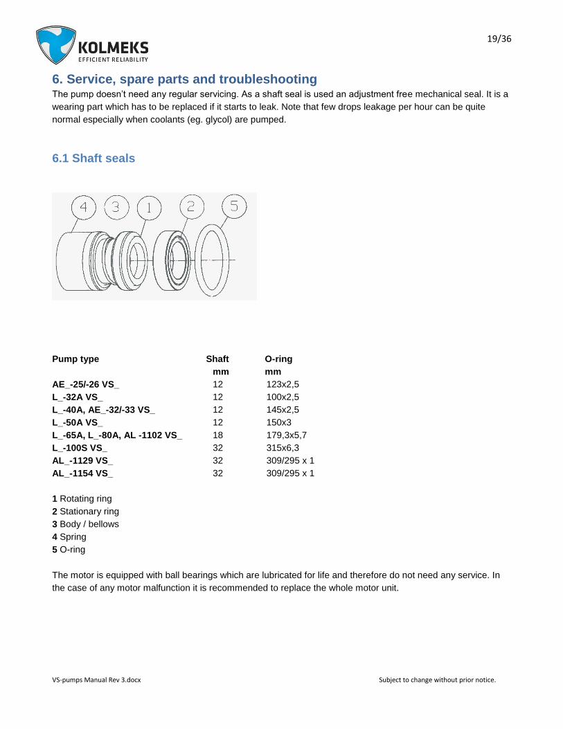
6.1 Shaft seals
Pump type Shaft O-ring
mm mm
AE_-25/-26 VS_ 12 123x2,5
L_-32A VS_ 12 100x2,5
L_-40A, AE_-32/-33 VS_ 12 145x2,5
L_-50A VS_ 12 150x3
L_-65A, L_-80A, AL -1102 VS_ 18 179,3x5,7
L_-100S VS_ 32 315x6,3
AL_-1129 VS_ 32 309/295 x 1
AL_-1154 VS_ 32 309/295 x 1
1 Rotating ring
2 Stationary ring
3 Body / bellows
4 Spring
5 O-ring
The motor is equipped with ball bearings which are lubricated for life and therefore do not need any service. In
the case of any motor malfunction it is recommended to replace the whole motor unit.
20/36
VS-pumps Manual Rev 3.docx Subject to change without prior notice.
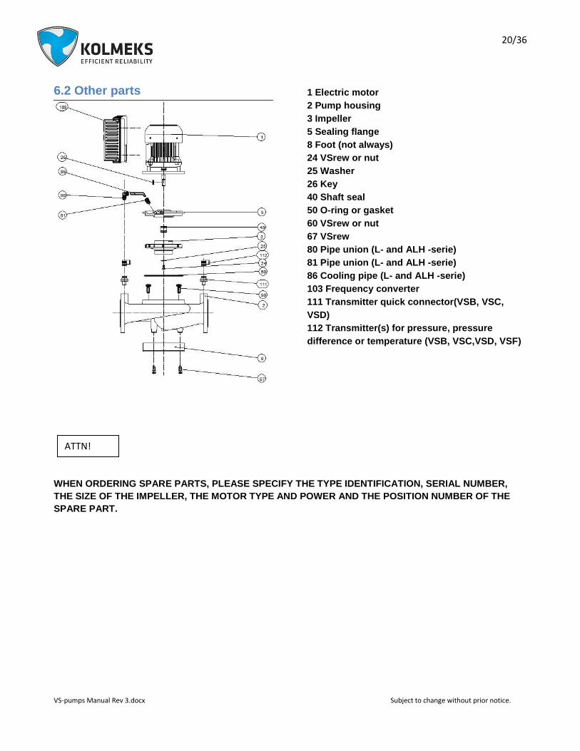
6.2 Other parts
1 Electric motor
2 Pump housing
3 Impeller
5 Sealing flange
8 Foot (not always)
24 VSrew or nut
25 Washer
26 Key
40 Shaft seal
50 O-ring or gasket
60 VSrew or nut
67 VSrew
80 Pipe union (L- and ALH -serie)
81 Pipe union (L- and ALH -serie)
86 Cooling pipe (L- and ALH -serie)
103 Frequency converter
111 Transmitter quick connector(VSB, VSC,
VSD)
112 Transmitter(s) for pressure, pressure
difference or temperature (VSB, VSC,VSD, VSF)
WHEN ORDERING SPARE PARTS, PLEASE SPECIFY THE TYPE IDENTIFICATION, SERIAL NUMBER,
THE SIZE OF THE IMPELLER, THE MOTOR TYPE AND POWER AND THE POSITION NUMBER OF THE
SPARE PART.
ATTN!

21/36
VS-pumps Manual Rev 3.docx Subject to change without prior notice.
6.3 Troubleshooting
Trouble Fault Fixing
Shaft seal is
leaking.
Wearing. Change the seal.
Pump has run dry. Change the seal.
Pump doesn’t
run.
The shaft of the pump is blocked. Check the free rotation of the shaft by turning the motor fan. If required, loosen the motor unit from the pump housing and repair the cause of the block.
Fuses have worked. Repair the cause of the fault. Change the fuses. If necessary, call the expert.
No electricity. Check and repair connections. If necessary, call the expert.
The disorder has stopped the pump. Reset the pump by disconnecting the supply voltage at least for 10 seconds.
Control wiring is not correct. Check the wiring in accordance with the
control diagram. Between terminals PC-
STF must be jumpered or closed switch.
The parametres of the frequency converter are changed or the pump is stopped with local control panel.
Correct the parameters or start the pump with the local control panel (not included in standard delivery). If necessary, call the expert.
The frequency converter or electric motor is damaged.
Replace the frequency converter and/or electric motor with a new one. Contact to Kolmeks.
If the pump is operated when
cover of the frequency converter
is open, the special carefulness
must be observed.
Pump stops by
itself or runs
irregular and
noisy.
The supply voltage is defective. One phase is possible missing.
Check the supply voltage. Check and repair fuses and connections of the cables.
The frequency converter or electric motor is damaged.
Replace the complete motor unit with frequency converter with a new one. Contact to Kolmeks.
ATTN!
22/36
VS-pumps Manual Rev 3.docx Subject to change without prior notice.
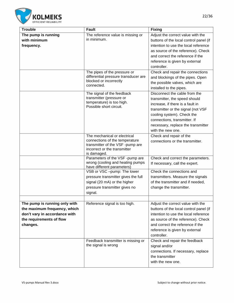
Trouble Fault Fixing
The pump is running
with minimum
frequency.
The reference value is missing or in minimum.
Adjust the correct value with the
buttons of the local control panel (if
intention to use the local reference
as source of the reference). Check
and correct the reference if the
reference is given by external
controller.
The pipes of the pressure or differential pressure transducer are blocked or incorrectly connected.
Check and repair the connections
and blockings of the pipes. Open
the possible valves, which are
installed to the pipes.
The signal of the feedback transmitter (pressure or temperature) is too high. Possible short circuit.
Disconnect the cable from the
transmitter, the speed should
increase, if there is a fault in
transmitter or the signal (not VSF
cooling system). Check the
connections, transmitter. If
necessary, replace the transmitter
with the new one.
The mechanical or electrical connections of the temperature transmitter of the VSF -pump are incorrect or the transmitter is damaged.
Check and repair of the
connections or the transmitter.
Parameters of the VSF -pump are wrong (cooling and heating pumps have different parameters)
Check and correct the parameters.
If necessary, call the expert.
VSB or VSC –pump: The lower
pressure transmitter gives the full
signal (20 mA) or the higher
pressure transmitter gives no
signal.
Check the connections and
transmitters. Measure the signals
of the transmitter and if needed,
change the transmitter.
The pump is running only with
the maximum frequency, which
don’t vary in accordance with
the requirements of flow
changes.
Reference signal is too high. Adjust the correct value with the
buttons of the local control panel (if
intention to use the local reference
as source of the reference). Check
and correct the reference if the
reference is given by external
controller.
Feedback transmitter is missing or the signal is wrong
Check and repair the feedback
signal and/or
connections. If necessary, replace
the transmitter
with the new one.
23/36
VS-pumps Manual Rev 3.docx Subject to change without prior notice.
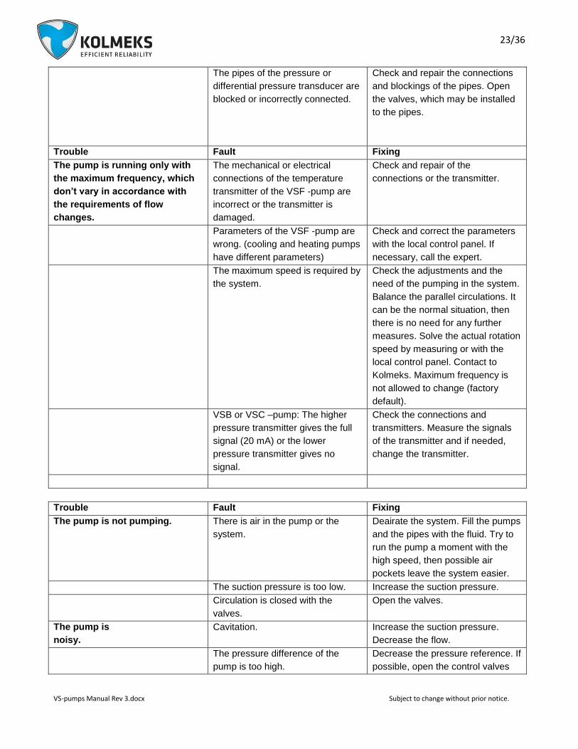
The pipes of the pressure or
differential pressure transducer are
blocked or incorrectly connected.
Check and repair the connections
and blockings of the pipes. Open
the valves, which may be installed
to the pipes.
Trouble Fault Fixing
The pump is running only with
the maximum frequency, which
don’t vary in accordance with
the requirements of flow
changes.
The mechanical or electrical
connections of the temperature
transmitter of the VSF -pump are
incorrect or the transmitter is
damaged.
Check and repair of the
connections or the transmitter.
Parameters of the VSF -pump are
wrong. (cooling and heating pumps
have different parameters)
Check and correct the parameters
with the local control panel. If
necessary, call the expert.
The maximum speed is required by
the system.
Check the adjustments and the
need of the pumping in the system.
Balance the parallel circulations. It
can be the normal situation, then
there is no need for any further
measures. Solve the actual rotation
speed by measuring or with the
local control panel. Contact to
Kolmeks. Maximum frequency is
not allowed to change (factory
default).
VSB or VSC –pump: The higher
pressure transmitter gives the full
signal (20 mA) or the lower
pressure transmitter gives no
signal.
Check the connections and
transmitters. Measure the signals
of the transmitter and if needed,
change the transmitter.
Trouble Fault Fixing
The pump is not pumping. There is air in the pump or the
system.
Deairate the system. Fill the pumps
and the pipes with the fluid. Try to
run the pump a moment with the
high speed, then possible air
pockets leave the system easier.
The suction pressure is too low. Increase the suction pressure.
Circulation is closed with the
valves.
Open the valves.
The pump is
noisy.
Cavitation. Increase the suction pressure.
Decrease the flow.
The pressure difference of the
pump is too high.
Decrease the pressure reference. If
possible, open the control valves

24/36
VS-pumps Manual Rev 3.docx Subject to change without prior notice.
and decrease the pressure
reference, then the head of the
pump is lower and the flow remains
the same.
There is a faulty shaft seal or
bearings.
Continuous rough noise refers to
the faulty bearings. High noise, few
seconds long, occasionally refers
to the faulty shaft seal. Replace
faulty bearings and shaft seal with
the new ones. If necessary, contact
Kolmeks.
Electrical noise from the frequency
converter or electric motor.
Replace the motor with the new
one. If necessary, correct the
parameters of the frequency
converter. Contact
Kolmeks.
25/36
VS-pumps Manual Rev 3.docx Subject to change without prior notice.
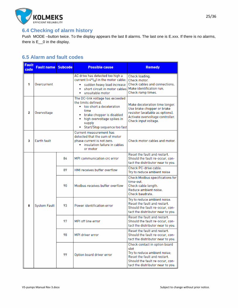
6.4 Checking of alarm history Push MODE –button twice. To the display appears the last 8 alarms. The last one is E.xxx. If there is no alarms,
there is E__0 in the display.
6.5 Alarm and fault codes

26/36
VS-pumps Manual Rev 3.docx Subject to change without prior notice.

27/36
VS-pumps Manual Rev 3.docx Subject to change without prior notice.

28/36
VS-pumps Manual Rev 3.docx Subject to change without prior notice.
29/36
VS-pumps Manual Rev 3.docx Subject to change without prior notice.
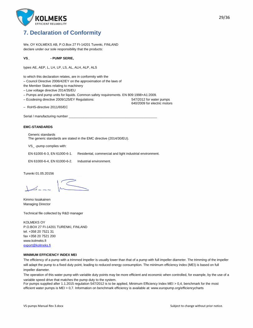
7. Declaration of Conformity
We, OY KOLMEKS AB, P.O.Box 27 FI-14201 Turenki, FINLAND
declare under our sole responsibility that the products:
VS_ - PUMP SERIE,
types AE, AEP, L, LH, LP, LS, AL, ALH, ALP, ALS
to which this declaration relates, are in conformity with the
– Council Directive 2006/42/EY on the approximation of the laws of
the Member States relating to machinery
– Low voltage directive 2014/35/EU
– Pumps and pump units for liquids. Common safety requirements. EN 809:1998+A1:2009.
– Ecodesing directive 2009/125/EY Regulations: 547/2012 for water pumps 640/2009 for electric motors
– RoHS-directive 2011/65/EC
Serial / manufacturing number ________________________________________________
EMC-STANDARDS Generic standards The generic standards are stated in the EMC directive (2014/30/EU). VS_ -pump complies with: EN 61000-6-3, EN 61000-6-1. Residental, commercial and light industrial environment. EN 61000-6-4, EN 61000-6-2. Industrial environment.
Turenki 01.05.20156
Kimmo Issakainen
Managing Director
Technical file collected by R&D manager
KOLMEKS OY
P.O.BOX 27 FI-14201 TURENKI, FINLAND
tel. +358 20 7521 31
fax +358 20 7521 200
www.kolmeks.fi
MINIMUM EFFICIENCY INDEX MEI
The efficiency of a pump with a trimmed impeller is usually lower than that of a pump with full impeller diameter. The trimming of the impeller
will adapt the pump to a fixed duty point, leading to reduced energy consumption. The minimum efficiency index (MEI) is based on full
impeller diameter.
The operation of this water pump with variable duty points may be more efficient and economic when controlled, for example, by the use of a
variable speed drive that matches the pump duty to the system. For pumps supplied after 1.1.2015 regulation 547/2012 is to be applied, Minimum Efficiency Index MEI > 0,4, benchmark for the most
efficient water pumps is MEI > 0,7. Information on benchmark efficiency is available at: www.europump.org/efficiencycharts

30/36
VS-pumps Manual Rev 3.docx Subject to change without prior notice.
8. Annex
8.1 Wiring diagram VSA-single pump

31/36
VS-pumps Manual Rev 3.docx Subject to change without prior notice.
8.2 Wiring diagram VSB-single pump
32/36
VS-pumps Manual Rev 3.docx Subject to change without prior notice.
8.3 Wiring diagram VSC-single pump
33/36
VS-pumps Manual Rev 3.docx Subject to change without prior notice.
8.4 Wiring diagram VSD-single pump
34/36
VS-pumps Manual Rev 3.docx Subject to change without prior notice.
8.5 Wiring diagram VSF-single pump
35/36
VS-pumps Manual Rev 3.docx Subject to change without prior notice.
8.6 Wiring diagram VSG-single pump

36/36
VS-pumps Manual Rev 3.docx Subject to change without prior notice.
8.7 Wiring diagram VSM-single pump