Embed Size (px)
Citation preview

open
ETC
SO
ETC
S/W
P5/
M5.
1
ITEA2 ProjectCall 6 110252012 – 2015
openETCS@ITEA Work-Package 5: “Demonstrator”
EVC simulator architecture
Eric Schellenberg, Nicolas Van Landeghem, Didier Weckmann,Alexis Julin
June 2014
Confidential – only for members of the consortium, including ITEA2 services.

This page is intentionally left blank

OETCS/WP5/M5.1 i
openETCS@ITEA Work-Package 5: “Demonstrator” OETCS/WP5/M5.1June 2014
EVC simulator architecture
Document approbation
Lead author: Technical assessor: Quality assessor: Project lead:
location / date location / date location / date location / date
signature signature signature signature
Alexis Julin Nicolas Van Landeghem Ainhoa Gracia Klaus-Rüdiger Hase
(ERSA) (ERSA) (SQS) (DB Netz)
Eric Schellenberg, Nicolas Van Landeghem, Didier Weckmann, Alexis Julin
ERSA5 Rue Maurice Blin67500 Haguenau, France
Final Report
Prepared for openETCS@ITEA2 Project
Confidential – only for members of the consortium, including ITEA2 services.

OETCS/WP5/M5.1 ii
Abstract: The purpose of this document is to describe the architecture of the EVC simulator: itsbreakdown into modules, the exchanged data, and the interfaces with external devices. The EVCsimulator behaves according to the SRS Class 1 version 3.3.0. The first part of this documentdescribes the context of the EVC simulator, its interfaces and its breakdown into modules. Thefollowing parts describe for each modules of the ERSA EVC simulator the exchanged data, theallocated functions.
Confidential – only for members of the consortium, including ITEA2 services.

OETCS/WP5/M5.1 iii
Modification History
Version Section Modification / Description Author
0.1Allparts
Creation Eric Schellenberg
1.0Allparts
Official version Eric Schellenberg
1.1Allparts
Update Eric Schellenberg
2.0Allparts
Update for OpenETCS review Alexis Julin
2.1Allparts
Update with SQS review comments Nicolas Van Landeghem
Confidential – only for members of the consortium, including ITEA2 services.

OETCS/WP5/M5.1 iv
Table of ContentsModification History.............................................................................................................. iii
Figures and Tables................................................................................................................. viii
1 Introduction....................................................................................................................... 1
1.1 Overview of European Vital Computer (EVC) ..................................................................... 1
1.2 Limitations .................................................................................................................. 2
2 System overview................................................................................................................ 3
2.1 Context diagram .......................................................................................................... 3
2.1.1 EVC simulator.................................................................................................... 3
2.1.2 EuroBalise transmitter ......................................................................................... 4
2.1.3 EuroLoop transmitter ........................................................................................... 4
2.1.4 EuroRadio......................................................................................................... 4
2.1.5 Odometer ......................................................................................................... 4
2.1.6 TIU .................................................................................................................. 4
2.1.7 DMI ................................................................................................................. 4
2.1.8 GUI/Diagnostic................................................................................................... 4
2.1.9 JRU ................................................................................................................. 4
2.2 Architecture diagram..................................................................................................... 5
3 Train interface manager ...................................................................................................... 8
3.1 Overview.................................................................................................................... 8
3.2 Exchanged data........................................................................................................... 8
3.2.1 Input data ......................................................................................................... 8
3.2.2 Output data ....................................................................................................... 9
3.3 Functions .................................................................................................................. 11
3.3.1 Initialize the external communication ...................................................................... 11
3.3.2 Manage odometric data ...................................................................................... 11
3.3.3 Manage TIU data............................................................................................... 12
3.3.4 Close the external communication ......................................................................... 12
4 Balise/loop interface manager............................................................................................. 13
4.1 Overview................................................................................................................... 13
4.2 Exchanged data.......................................................................................................... 13
4.2.1 Input data ........................................................................................................ 13
4.2.2 Output data ...................................................................................................... 13
4.3 Functions .................................................................................................................. 15
4.3.1 Initialize the external communication ...................................................................... 15
4.3.2 Manage loop message........................................................................................ 16
4.3.3 Manage balise message ..................................................................................... 16
4.3.4 Manage data from internal module ........................................................................ 16
4.3.5 Manage linking.................................................................................................. 16
4.3.6 Manage brake due to balise inconsistency .............................................................. 16
4.3.7 Manage big metal masses ................................................................................... 16
4.3.8 Close the external communication ......................................................................... 16
Confidential – only for members of the consortium, including ITEA2 services.

OETCS/WP5/M5.1 v
5 DMI interface manager ....................................................................................................... 17
5.1 Overview................................................................................................................... 17
5.2 Exchanged data.......................................................................................................... 17
5.2.1 Input data ........................................................................................................ 17
5.2.2 Output data ...................................................................................................... 18
5.3 Functions .................................................................................................................. 19
5.3.1 Initialize the external communication ...................................................................... 20
5.3.2 Send periodical data to DMI ................................................................................. 20
5.3.3 Manage text message ........................................................................................ 20
5.3.4 Manage TAF..................................................................................................... 20
5.3.5 Manage data from internal modules ....................................................................... 20
5.3.6 Manage available option...................................................................................... 20
5.3.7 Manage data from DMI ....................................................................................... 20
5.3.8 Close the external communication ......................................................................... 20
6 Radio interface manager .................................................................................................... 21
6.1 Overview................................................................................................................... 21
6.2 Exchanged data.......................................................................................................... 21
6.2.1 Input data ........................................................................................................ 21
6.2.2 Output data ...................................................................................................... 21
6.3 Functions .................................................................................................................. 23
6.3.1 Manage data from internal module ........................................................................ 23
6.3.2 Supervise radio link............................................................................................ 23
6.3.3 Manage RBC transition ....................................................................................... 24
7 EuroRadio interface manager ............................................................................................. 25
7.1 Overview................................................................................................................... 25
7.2 Exchanged data.......................................................................................................... 25
7.2.1 Input data ........................................................................................................ 25
7.2.2 Output data ...................................................................................................... 25
7.3 Functions .................................................................................................................. 26
7.3.1 Initialize the external communication ...................................................................... 26
7.3.2 Manage data from internal module ........................................................................ 26
7.3.3 Manage EuroRadio message ............................................................................... 26
7.3.4 Close the external communication ......................................................................... 26
8 Recorder interface manager ............................................................................................... 28
8.1 Overview................................................................................................................... 28
8.2 Exchanged data.......................................................................................................... 28
8.2.1 Input data ........................................................................................................ 28
8.2.2 Output data ...................................................................................................... 28
8.3 Functions .................................................................................................................. 29
8.3.1 Initialize the external communication ...................................................................... 29
8.3.2 Manage data from internal module ........................................................................ 29
8.3.3 Record changes ................................................................................................ 29
8.3.4 Close the external communication ......................................................................... 29
9 Data manager ................................................................................................................... 30
9.1 Overview................................................................................................................... 30
9.2 Exchanged data.......................................................................................................... 30
Confidential – only for members of the consortium, including ITEA2 services.

OETCS/WP5/M5.1 vi
9.2.1 Input data ........................................................................................................ 30
9.2.2 Output data ...................................................................................................... 31
9.3 Functions .................................................................................................................. 33
9.3.1 Manage data from internal modules ....................................................................... 33
9.3.2 Manage MA request ........................................................................................... 34
9.3.3 Manage position report ....................................................................................... 34
9.3.4 Manage RIU area .............................................................................................. 34
9.3.5 Manage data in level transition area....................................................................... 34
9.3.6 Manage national data ......................................................................................... 34
9.3.7 Manage track conditions ..................................................................................... 34
9.3.8 Manage route suitability ...................................................................................... 34
9.3.9 Manage emergency stop ..................................................................................... 34
9.3.10 Manage geographical position .............................................................................. 34
10 Movement limitation computer ............................................................................................ 36
10.1 Overview................................................................................................................... 36
10.2 Exchanged data.......................................................................................................... 36
10.2.1 Input data ........................................................................................................ 36
10.2.2 Output data ...................................................................................................... 37
10.3 Functions .................................................................................................................. 38
10.3.1 Manage data from internal module ........................................................................ 38
10.3.2 Manage reduction of MA at standstill...................................................................... 39
10.3.3 Manage MA timers............................................................................................. 39
10.3.4 Update movement authorization............................................................................ 39
10.3.5 Manage track description .................................................................................... 39
11 Train movement controller.................................................................................................. 40
11.1 Overview................................................................................................................... 40
11.2 Exchanged data.......................................................................................................... 40
11.2.1 Input data ........................................................................................................ 40
11.2.2 Output data ...................................................................................................... 41
11.3 Functions .................................................................................................................. 42
11.3.1 Manage data from internal module ........................................................................ 42
11.3.2 Control train speed and location............................................................................ 43
11.3.3 Manage brake request ........................................................................................ 43
11.3.4 Standstill supervision.......................................................................................... 43
11.3.5 Roll away protection ........................................................................................... 43
11.3.6 Reverse movement protection .............................................................................. 43
11.3.7 Apply brake change ........................................................................................... 43
12 Mode/level manager .......................................................................................................... 44
12.1 Overview................................................................................................................... 44
12.2 Exchanged data.......................................................................................................... 44
12.2.1 Input data ........................................................................................................ 44
12.2.2 Output data ...................................................................................................... 45
12.3 Functions .................................................................................................................. 46
12.3.1 Manage data from internal module ........................................................................ 46
12.3.2 Manage on-board status ..................................................................................... 47
12.3.3 Manage train data status ..................................................................................... 47
12.3.4 Manage mode profile.......................................................................................... 47
Confidential – only for members of the consortium, including ITEA2 services.

OETCS/WP5/M5.1 vii
12.3.5 Manage level transition ....................................................................................... 47
12.3.6 Manage reversing area ....................................................................................... 47
12.3.7 Manage override EOA ........................................................................................ 47
12.3.8 Manage end of mission ....................................................................................... 47
Appendix A: Glossary ............................................................................................................. 48
Appendix B: Odometric data .................................................................................................... 49
Appendix C: TIU data .............................................................................................................. 50
Appendix D: EuroRadio data .................................................................................................... 53
D.1 Format of the exchanged primitives ................................................................................. 53
D.1.1 Connection request ............................................................................................ 54
D.1.2 Connection indication ......................................................................................... 54
D.1.3 Connection response.......................................................................................... 55
D.1.4 Connection confirmation ..................................................................................... 55
D.1.5 Data request..................................................................................................... 55
D.1.6 Data indication .................................................................................................. 56
D.1.7 Hight priority data request.................................................................................... 56
D.1.8 Hight priority data indication ................................................................................. 56
D.1.9 Disconnection request ........................................................................................ 57
D.1.10Disconnection indication...................................................................................... 57
Confidential – only for members of the consortium, including ITEA2 services.

OETCS/WP5/M5.1 viii
Figures and Tables
Figures
Figure 1. Overview of ETCS Onboard ............................................................................................ 1
Figure 2. Context diagram ........................................................................................................... 3
Figure 3. Architecture diagrams .................................................................................................... 5
Figure 4. Train interface manager, sequence diagram....................................................................... 11
Figure 5. Balise/loop interface manager, sequence diagram............................................................... 15
Figure 6. DMI interface manager, sequence diagram........................................................................ 19
Figure 7. Radio interface manager, sequence diagram ..................................................................... 23
Figure 8. EuroRadio interface manager, sequence diagram ............................................................... 26
Figure 9. Recorder interface manager, sequence diagram ................................................................. 29
Figure 10. Data manager, sequence diagram ................................................................................. 33
Figure 11. Movement limitation computer, sequence diagram............................................................. 38
Figure 12. Train movement controller, sequence diagram .................................................................. 42
Figure 13. Mode/level manager, sequence diagram ......................................................................... 46
Tables
Table 1. Train interface manager: Input data .................................................................................... 8
Table 2. Train interface manager: Output data.................................................................................. 9
Table 3. Balise/loop interface manager: Input data ........................................................................... 13
Table 4. Balise/loop interface manager: Output data ........................................................................ 13
Table 5. DMI interface manager: Input data .................................................................................... 17
Table 6. DMI interface manager: Output data.................................................................................. 18
Table 7. Radio interface manager: Input data.................................................................................. 21
Table 8. Radio interface manager: Output data ............................................................................... 22
Table 9. EuroRadio interface manager: Input data ........................................................................... 25
Table 10. EuroRadio interface manager: Output data ....................................................................... 25
Table 11. Recorder interface manager: Input data ........................................................................... 28
Table 12. Recorder interface manager: Output data ......................................................................... 28
Table 13. Data manager: Input data.............................................................................................. 30
Table 14. Data manager: Output data ........................................................................................... 31
Table 15. Movement limitation computer: Input data ......................................................................... 36
Table 16. Movement limitation computer: Output data....................................................................... 37
Table 17. Train movement controller: Input data .............................................................................. 40
Table 18. Train movement controller: Output data ............................................................................ 41
Table 19. Mode/level manager: Input data...................................................................................... 44
Table 20. Mode/level manager: Output data ................................................................................... 45
Table A1. Glossary ................................................................................................................... 48
Table B1. Odometric data ........................................................................................................... 49
Table C1. TIU received data........................................................................................................ 50
Table C2. TIU sent data ............................................................................................................. 51
Table D1. Connection on EVC initiative ......................................................................................... 53
Table D2. Connection on RBC initiative ......................................................................................... 53
Table D3. Transmission of data .................................................................................................... 53
Table D4. Disconnection ............................................................................................................ 53
Confidential – only for members of the consortium, including ITEA2 services.

OETCS/WP5/M5.1 ix
Table D5. Format of the exchanged primitives................................................................................. 54
Table D6. Connection request ..................................................................................................... 54
Table D7. Connection indication................................................................................................... 54
Table D8. Connection response ................................................................................................... 55
Table D9. Connection confirmation ............................................................................................... 55
Table D10. Data request ............................................................................................................ 55
Table D11. Data indication.......................................................................................................... 56
Table D12. Hight priority data request ........................................................................................... 56
Table D13. Hight priority data indication......................................................................................... 56
Table D14. Disconnection request ................................................................................................ 57
Table D15. Disconnection indication ............................................................................................. 57
Confidential – only for members of the consortium, including ITEA2 services.

OETCS/WP5/M5.1 x
Confidential – only for members of the consortium, including ITEA2 services.

OETCS/WP5/M5.1 1
1 Introduction
1.1 Overview of European Vital Computer (EVC)
The European Vital Computer (EVC) is the brain or kernel of the ERTMS/ETCS system which isinstalled in trains. It allows the safe movement of trains on lines equipped with ERTMS/ETCS.It uses a certain number of interfaces with other equipments. Some of them are defined asmandatory at FFFIS or FIS level, and some others are not standard.
Figure 1. Overview of ETCS Onboard
• MMI: this interface is in fact the DMI product, which has a non standardized interface to theEVC;
• TIU: this interface defined at FIS level allows the communication with the train;
• BTM: this interface defined at FFFIS level reads the balise telegrams;
• LTM: this interface defined at FFFIS level reads the loop telegrams;
• Euroradio (RIM): this interface defined at FFFIS level allows the communication by radio;
• Odometry: this module calculates the travelled distance, train speed and accelerations;
• JRU: this module records all events occurring in the train; the extraction of data is defined atFFFIS level;
Confidential – only for members of the consortium, including ITEA2 services.

OETCS/WP5/M5.1 2
• STM: this module exists in theory in two versions: national or European; it converts as faras possible national information into ETCS information, including braking the train, whenappropriate. It is optional in openETCS’ scope.
1.2 Limitations
The mode STM European is not supported.
Confidential – only for members of the consortium, including ITEA2 services.

OETCS/WP5/M5.1 3
2 System overview
2.1 Context diagram
Figure 2. Context diagram
2.1.1 EVC simulator
The EVC simulator is, fundamentally, the centre of all the control process and protection of thetrain movement. It performs the following main tasks:
• it checks the state of the system and performs all mode and level transitions;
• it validates the data entered by the driver;
• it calculates the train supervision curves;
• it reads the balise, loop and radio telegrams and processes the data;
• it validates the RBC messages and processes the data;
• it transmits the train location and other information to the RBC;
• it manages the movement authorities from the RBC, balises or loops;
• it calculates the most restrictive speed limits for the current train location;
Confidential – only for members of the consortium, including ITEA2 services.

OETCS/WP5/M5.1 4
• it supervises the train movements (including the protection against undesirable movement)and triggers warnings and interventions;
• it records all events occurring in the system.
2.1.2 EuroBalise transmitter
The EuroBalise transmitter manages the reception of the balise messages and transmits them tothe EVC simulator. The useful data are binary balise messages according to SRS Class 1 v3.3.0,Chapter 7&8. It is a simplified BTM.
2.1.3 EuroLoop transmitter
The EuroLoop transmitter manages the reception of the loop messages and transmits them tothe EVC simulator. The useful data are binary loop messages according to SRS Class 1 v3.3.0,Chapter 7&8. It is a simplified LTM.
2.1.4 EuroRadio
The EuroRadio manages the interface with the radio network. It manages the connection andthe exchanged of data between the EVC simulator and the RBC / RIU. The exchanged data arecomposed of radio primitives and radio messages. The format of the exchanged messages isdescribed in Appendix D (page 53)
2.1.5 Odometer
The Odometer transmits to the EVC simulator the train location data (position, speed, accelera-tion). The odometric data are described in Appendix B (page 49)
2.1.6 TIU
The TIU manages the interface between the EVC simulator and the train equipment. It receivessome commands from the EVC simulator (service brake application, emergency brake application,...) and transmits some status (main power switch, cabin open, service brake applied, ...). TheTIU data are described in Appendix C (page 50)
2.1.7 DMI
The DMI manages the interface with the driver. It receives from the EVC simulator the informa-tion to displayed to the driver (train speed, permitted speed, track description, ...) and it transmitsthe driver action (train data entry, shunting request, ...). The data are exchanged according tospecification for EVC-DMI communication (see /6/). The DMI interface is according to /6/.
2.1.8 GUI/Diagnostic
The GUI / diagnostic interface is specific to the EVC simulator. It displays the status of internaldata of the EVC simulator and the operator can send some commands.
2.1.9 JRU
The JRU receives the juridical data to record. The format of the binary frame is according to /1/.
Confidential – only for members of the consortium, including ITEA2 services.

OETCS/WP5/M5.1 5
2.2 Architecture diagram
Figure 3. Architecture diagrams
The EVC simulator has been divided into 10 separate modules (a module is implemented by aperiodic thread). The communication between the modules is performed via an internal mailboxand shared memories.
• Train interface manager: it performs the following tasks:
– It receives and processes the odometric data to update the internal location data.
– It updates the EVC commands on the TIU.
– It gets the train statuses from the TIU.
• Balise/loop interface manager: it performs the following tasks:
– It receives and decodes the balise and loop message.
– It manages the balise groups.
– It manages the balise linking.
– It manages the track condition about big metal masses.
• DMI interface manager: it performs the following tasks:
– It manages the communication with the DMI.
– It sends relevant data for display.
– It manages the train data entry.
– It gets the driver request.
Confidential – only for members of the consortium, including ITEA2 services.

OETCS/WP5/M5.1 6
• Radio interface manager: it performs the following tasks:
– It manages the radio session with RBC/RIU.
– It receives and decodes the radio messages.
– It builds and sends radio messages.
– It manages the supervision of the radio link.
– It manages the RBC transition.
• EuroRadio interface manager: it performs the following tasks:
– It manages the communication with the EuroRadio.
– It manages the safe radio connection.
– It transmits the radio messages.
• Recorder interface manager: it performs the following tasks:
– It manages the recording of juridical data.
• Data manager: it performs the following tasks:
– It manages the received data from trackside: apply filter according to the ETCSmode/level and current level transition, dispatch data to the other modules.
– It manages the track condition.
– It manages the national data.
– It manages the route suitability data.
– It manages the emergency stop.
– It manages the operator action on the GUI.
• Movement limitation computer: it performs the following tasks:
– It computes and provides supervision data according to ETCS mode/level.
– It manages the track description: static speed profile, gradient profile, temporary speedrestriction, axle load speed profile.
– It manages reduction of movement authority according to conditional emergency stop,route unsuitability, mode profile.
• Train movement controller: it performs the following tasks:
– It manages the supervision of the train movement according to the ETCS mode and theavailable supervision data.
– It manages the service brakes and emergency brakes requests.
– It supervises an area according to a list of balise group (in shunting or staff responsiblemode).
• Mode/level manager: it performs the following tasks:
– It manages the EVC status, ETCS mode and level.
– It manages the level transition.
– It manages the reversing area.
– It manages the Override EOA.
– It manages the mode profile.
Confidential – only for members of the consortium, including ITEA2 services.

OETCS/WP5/M5.1 7
There is one additional module: the EVC simulator controller. It performs the following maintasks:
• It creates the shared memories.
• It gets the configuration data to initialise the shared memories and to configure the EVCsimulation.
• It creates the internal mailbox of the EVC simulator.
• It manages the start and stop of the other modules.
Confidential – only for members of the consortium, including ITEA2 services.
OETCS/WP5/M5.1 8
3 Train interface manager
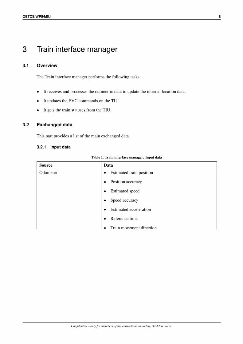
3.1 Overview
The Train interface manager performs the following tasks:
• It receives and processes the odometric data to update the internal location data.
• It updates the EVC commands on the TIU.
• It gets the train statuses from the TIU.
3.2 Exchanged data
This part provides a list of the main exchanged data.
3.2.1 Input data
Table 1. Train interface manager: Input data
Source Data
Odometer • Estimated train position
• Position accuracy
• Estimated speed
• Speed accuracy
• Estimated acceleration
• Reference time
• Train movement direction
Confidential – only for members of the consortium, including ITEA2 services.

OETCS/WP5/M5.1 9
TIU • Main power switch status
• Train integrity status
• Active cabin
• Sleeping signal status
• Non leading permission
• Passive shunting permission
• Direction controller position
• Regenerative brake status
• Magnetic shoe brake status
• Eddy current brake status
• Electro Pneumatic brake status
• Additional brake status
• Train data information
• Type of train data entry
• Traction status
• National system isolation status
• Brake pressureShared memories • Odometry error model
• TIU data (outputs)
3.2.2 Output data
Table 2. Train interface manager: Output data
Destination Data
Confidential – only for members of the consortium, including ITEA2 services.

OETCS/WP5/M5.1 10
TIU • Service Brake command
• Emergency Brake command
• Traction Cut-Off command
• Regenerative Brake inhibition
• Magnetic Shoe Brake inhibition
• Eddy Current Brake for SB inhibition
• Eddy Current Brake for EB inhibition
• Change of traction system
• Pantograph command
• Air Tightness command
• Main Power Switch command (sometimes named maincircuit breaker)
• Isolation status
• Station location
• Allowed current consumptionShared memories • TIU data (inputs)
• Train location data
Confidential – only for members of the consortium, including ITEA2 services.

OETCS/WP5/M5.1 11
3.3 Functions
The following functions are performed by the Train interface manager:
Figure 4. Train interface manager, sequence diagram
3.3.1 Initialize the external communication
It initialises the communication with the Odometer. It initialises the communication with theTIU.
3.3.2 Manage odometric data
It gets the odometric data (position, speed, acceleration) of the train. It calculates the internaltrain location data (train front location, train rear location, ...):
• It converts the location data in train coordinate according to the active cabin: the distanceincrement direction is the train orientation defined by the active cabin.
• It calculates the location error according to the error model.
Confidential – only for members of the consortium, including ITEA2 services.

OETCS/WP5/M5.1 12
It updates the train location data stored in shared memory.
3.3.3 Manage TIU data
It updates the EVC commands on TIU from data in the shared memories. It gets the train statusesfrom TIU and stores them in the shared memories.
3.3.4 Close the external communication
It closes the communication with the Odometer. It closes the communication with the TIU.
Confidential – only for members of the consortium, including ITEA2 services.

OETCS/WP5/M5.1 13
4 Balise/loop interface manager
4.1 Overview
The Balise/loop interface manager performs the following tasks:
• It receives and decodes the balise and loop message.
• It manages the balise groups.
• It manages the balise linking.
• It manages the track condition about big metal masses.
4.2 Exchanged data
4.2.1 Input data
Table 3. Balise/loop interface manager: Input data
Source Data
EuroBalise transmitter • Balise message
EuroLoop transmitter • Loop message
Data manager • Linking data
• Track condition about big metal masses
• Loop informationShared memories • Train location data
• Onboard status data
• LRBG data
• Train equipment
4.2.2 Output data
Table 4. Balise/loop interface manager: Output data
Destination Data
Data manager • Balise group message
• Loop messageTrain movement controller • Service brake application request
• Service brake release requestMovement limitation computer • MA reduction request
Confidential – only for members of the consortium, including ITEA2 services.

OETCS/WP5/M5.1 14
Mode/level manager • Train trip request
DMI interface manager • Track condition data about big metal masses
Shared memories • Current linking data
• LRBG data
• Indication of big metal masses (TIU data)
Confidential – only for members of the consortium, including ITEA2 services.

OETCS/WP5/M5.1 15
4.3 Functions
The following functions are performed by the Balise/loop interface manager:
Figure 5. Balise/loop interface manager, sequence diagram
4.3.1 Initialize the external communication
Confidential – only for members of the consortium, including ITEA2 services.

OETCS/WP5/M5.1 16
It initialises the communication with the EuroLoop transmitter. It initialises the communicationwith the EuroBalise transmitter.
4.3.2 Manage loop message
It receives and decodes the loop messages. It selects the data valid for the train direction accordingto the available information about the loop. It transmits the decoded loop message to the datamanager.
4.3.3 Manage balise message
It receives and decodes the balise messages. It manages the balise group and checks its consistency(place of balise in group, number of balise in group). It selects the data valid for the train directionaccording to the balise group orientation. It checks the balise group linking and applies therequired reaction if an inconsistency is detected. It transmits the valid balise group message tothe data manager.
4.3.4 Manage data from internal module
It receives and processes the following data from the others modules:
• new linking data: it is taken into account to update the current linking data used to check thebalise group linking.
• Loop information: it is stored and will be used for the management of loop message reception.
• Track condition about big metal masses: it is taken into account to update the current list oftrack condition.
4.3.5 Manage linking
It checks if a balise group has not been missed according to the current linking data and performsthe required reaction.
4.3.6 Manage brake due to balise inconsistency
If a service brakes application has been requested due to balise inconsistency, it manages therequest for the release of the service brakes when the train reaches standstill and it request thereduction of the movement authority to the current train location.
4.3.7 Manage big metal masses
It manages the current list of track condition about big metal masses and it ignores the balisereception alarm when the balise antenna is in an area with big metal masses.
4.3.8 Close the external communication
It closes the communication with the EuroLoop transmitter. It closes the communication with theEuroBalise transmitter.
Confidential – only for members of the consortium, including ITEA2 services.

OETCS/WP5/M5.1 17
5 DMI interface manager
5.1 Overview
The DMI interface manager performs the following tasks:
• It manages the communication with the DMI.
• It sends relevant data for display.
• It manages the train data entry.
• It gets the driver request.
5.2 Exchanged data
5.2.1 Input data
Table 5. DMI interface manager: Input data
Source Data
Data manager • Track condition
• Text message from tracksideBalise/loop interface manager • Track condition data about big metal masses
All modules • Text messages
Movement limitation computer • Track description (gradient profile, static speed profile,TSR)
Shared memories • On-board status data
• Train location data
• Route unsuitability indication
• Train data
• RBC data
• SR data
• TIU data
• Emergency stop
• Supervision data
• Radio communication status
• Reversing area indication
• Adhesion data
Confidential – only for members of the consortium, including ITEA2 services.

OETCS/WP5/M5.1 18
5.2.2 Output data
Table 6. DMI interface manager: Output data
Destination Data
All modules • Text message acknowledgement result
Train movement controller • Service brake application request
• Service brake release requestMode/level manager • Driver request (start, shunting, non leading, override, ...)
• Data entry (driver id, level, train data, ...)Data manager • Override route unsuitability
• Adhesion factor from driverMovement limitation computer • MA reduction request
• Request for new calculation of supervision dataShared memories • RBC data
• Train data
• SR data
Confidential – only for members of the consortium, including ITEA2 services.

OETCS/WP5/M5.1 19
5.3 Functions
The following functions are performed by the DMI interface manager:
Figure 6. DMI interface manager, sequence diagram
Confidential – only for members of the consortium, including ITEA2 services.

OETCS/WP5/M5.1 20
5.3.1 Initialize the external communication
It initialises the communication with the DMI.
5.3.2 Send periodical data to DMI
It builds and sends a message containing some data to be updated periodically on DMI: trainlocation, train speed, supervised speed, status of brakes, ETCS mode & level, ...
5.3.3 Manage text message
It manages the conditions to display or remove a text message on the DMI from a list of textmessage.
5.3.4 Manage TAF
It manages the display, the remove of the track ahead free request. It processes the acknowledg-ment.
5.3.5 Manage data from internal modules
It receives and processes the following data from the others modules:
• New text message to display: it adds the text message in the current list of text message tomanage.
• New track description: it builds and sends a message containing the track description (staticspeed profile, gradient profile, track condition, ...) to the DMI.
• Operator request via GUI: it manages the operation request performed on the GUI as it was adriver action performed on the DMI.
5.3.6 Manage available option
According to the On-board status, it builds and sends a message to the DMI containing theavailable option (entry of level, selection of shunting request, ...).
5.3.7 Manage data from DMI
It receives, decodes and processes the messages from the DMI:
• It manages the data entry (driver id, ETCS level, train data, ...) and informs the other modules.
• It gets the driver request (Shunting request, Start of Mission request, ...) and transmits themto the suitable module.
• It manages the text message acknowledgements.
5.3.8 Close the external communication
It closes the communication with the DMI.
Confidential – only for members of the consortium, including ITEA2 services.

OETCS/WP5/M5.1 21
6 Radio interface manager
6.1 Overview
The Radio interface manager performs the following tasks:
• It manages the radio session with RBC/RIU.
• It receives and decodes the radio messages.
• It builds and sends radio messages.
• It manages the supervision of the radio link.
• It manages the RBC transition.
6.2 Exchanged data
6.2.1 Input data
Table 7. Radio interface manager: Input data
Source Data
Data manager • Request to send a radio message
• RBC transition data
• Radio session data
• RBC connection /.disconnection requestMode /level manager • Request to send a radio message
• RBC connection /.disconnection requestEuroRadio interface manager • Connection / disconnection information
• Radio message receivedMovement limitation computer • Request to send a radio message
Shared memories • RBC data
• National values
• Train location data
• LRBG data
• Train data
6.2.2 Output data
Confidential – only for members of the consortium, including ITEA2 services.

OETCS/WP5/M5.1 22
Table 8. Radio interface manager: Output data
Destination Data
EuroRadio interface manager • Connection /.disconnection request
• Request to send a radio messageMode/level manager • Radio communication session open/closed
• Train trip requestTrain movement controller • Service brake application request
• Service brake release requestMovement limitation computer • MA reduction request
Data manager • Received radio message
Shared memories • Radio communication status
• RBC data
Confidential – only for members of the consortium, including ITEA2 services.

OETCS/WP5/M5.1 23
6.3 Functions
The following functions are performed by the Radio interface manager:
Figure 7. Radio interface manager, sequence diagram
6.3.1 Manage data from internal module
It receives and processes the following data from the others modules:
• Connection / disconnection request: it manages the radio communication session establish-ment / termination.
• Send message request: it builds and sends the requested message.
• New RBC transition data: it is stored for the management of the RBC transition.
• Connection / disconnection indication: it is taken into account for the management of theradio communication session.
• Reception of radio message: it is decoded, the timestamp consistency is checked, it checks theused LRBG, it selects the data valid for the train direction, it manages the acknowledgement,it manages the radio communication session and it transmits the message to the Data manager.
6.3.2 Supervise radio link
Confidential – only for members of the consortium, including ITEA2 services.

OETCS/WP5/M5.1 24
According to the national values, it checks the maximum time since the last received radiomessage when a radio communication session is established and it applies the required reaction.It manages the radio holes.
6.3.3 Manage RBC transition
It manages the RBC transition according to the available radio equipment (one or two equipmentsavailable).
Confidential – only for members of the consortium, including ITEA2 services.

OETCS/WP5/M5.1 25
7 EuroRadio interface manager
7.1 Overview
The EuroRadio interface manager performs the following tasks:
• It manages the communication with the EuroRadio.
• It manages the safe radio connection.
• It transmits the radio messages.
7.2 Exchanged data
7.2.1 Input data
Table 9. EuroRadio interface manager: Input data
Source Data
EuroRadio • Connection/disconnection indication
• Reception of radio messageRadio interface manager • Connection/disconnection request
• Request to send a radio message
7.2.2 Output data
Table 10. EuroRadio interface manager: Output data
Destination Data
Radio interface manager • Connection / disconnection information
• Radio message receivedEuroRadio • Connection / disconnection request
• Transmission of radio message requestShared memories • Radio connection status
Confidential – only for members of the consortium, including ITEA2 services.

OETCS/WP5/M5.1 26
7.3 Functions
The following functions are performed by the EuroRadio interface manager:
Figure 8. EuroRadio interface manager, sequence diagram
7.3.1 Initialize the external communication
It initialises the communication with the EuroRadio.
7.3.2 Manage data from internal module
It receives and processes the following data from the others modules:
• Connection/disconnection request: it builds and sends the message for the connection/disconnectionrequest to the EuroRadio.
• Data send request: it builds and sends the message for the data send request to the EuroRadio.
7.3.3 Manage EuroRadio message
It receives and decodes the messages from the EuroRadio, it manages the radio connection andit informs the Radio interface manager of the connection/disconnection and reception of radiomessage.
7.3.4 Close the external communication
Confidential – only for members of the consortium, including ITEA2 services.

OETCS/WP5/M5.1 27
It closes the communication with the EuroRadio.
Confidential – only for members of the consortium, including ITEA2 services.

OETCS/WP5/M5.1 28
8 Recorder interface manager
8.1 Overview
The Recorder interface manager performs the following tasks:
• It manages the recording of juridical data.
8.2 Exchanged data
8.2.1 Input data
Table 11. Recorder interface manager: Input data
Source Data
All modules • Juridical event to record
Shared memories • ETCS mode & level (on-board status)
• Train location data
8.2.2 Output data
Table 12. Recorder interface manager: Output data
Destination Data
JRU • Juridical data to record
Confidential – only for members of the consortium, including ITEA2 services.

OETCS/WP5/M5.1 29
8.3 Functions
The following functions are performed by the Recorder interface manager:
Figure 9. Recorder interface manager, sequence diagram
8.3.1 Initialize the external communication
It initialises the communication with the JRU.
8.3.2 Manage data from internal module
It receives the juridical event to record: it builds and sends the corresponding message to theJRU.
8.3.3 Record changes
It builds and sends message to the JRU for the record of periodical data (train location , speed,...) or when a juridical data changes (ETCS mode, level, ...)
8.3.4 Close the external communication
It closes the communication with the JRU.
Confidential – only for members of the consortium, including ITEA2 services.

OETCS/WP5/M5.1 30
9 Data manager
9.1 Overview
The Data manager performs the following tasks:
• It manages the received data from trackside: apply filter according to the ETCS mode/leveland current level transition, dispatch data to the other modules.
• It manages the track condition.
• It manages the national data.
• It manages the route suitability data.
• It manages the emergency stop.
• It manages the graphical user interface (GUI) and the information to display.
9.2 Exchanged data
9.2.1 Input data
Table 13. Data manager: Input data
Source Data
Balise/loop interface manager • Balise group message
• Loop messageDMI interface manager • Override route unsuitability
• Adhesion factor from driverMode/level manager • MA request
Radio interface manager • Received radio message
Movement limitation computer • MA request
Shared memories • On-board status data
• Level transition data
• Train location data
• Train data
• LRBG data
• Current linking data
• RBC dataGraphical User Interface • Simulation configuration data
• Simulation controls (stop function)
Confidential – only for members of the consortium, including ITEA2 services.

OETCS/WP5/M5.1 31
9.2.2 Output data
Table 14. Data manager: Output data
Destination Data
Movement limitation computer • Route unsuitability data
• Indication of new national data
• Repositioning information
• Track description (gradient, speed profile, ...)
• Mode profile
• Reversing supervision data
• Temporary speed restriction
• MA revocation request
• MA
• Emergency stopDMI interface manager • Track condition
• Text message from tracksideRadio interface manager • Request to send radio message
• RBC transition data
• Radio session data
• Connection / disconnection requestMode/level manager • Level transition data
• RBC answer (ack of train data, Shunting accepted/rejected,...)
• Mode profile
• Train trip request
• Reversing area dataTrain movement controller • Shunting area data
• Staff responsible area data
• Service brakes application request
• Service brakes release request
• Emergency brakes application request
• Emergency brakes release request
• New balise group indication
Confidential – only for members of the consortium, including ITEA2 services.

OETCS/WP5/M5.1 32
Balise/loop interface manager • Linking data
• Loop information
• Track condition about big metal massesShared memories • Track condition data
• Main circuit breaker open request (TIU data)
• Pantograph low request (TIU data)
• Inhibition of passenger emergency brakes request (TIUdata)
• Airtight request (TIU data)
• Switch off regenerative brakes request (TIU data)
• Switch off eddy current brakes request (TIU data)
• Switch off magnetic shoe brakes request (TIU data)
• National data
• Adhesion data
• Radio communication session status
Confidential – only for members of the consortium, including ITEA2 services.

OETCS/WP5/M5.1 33
9.3 Functions
The following functions are performed by the Data manager:
Figure 10. Data manager, sequence diagram
9.3.1 Manage data from internal modules
Confidential – only for members of the consortium, including ITEA2 services.

OETCS/WP5/M5.1 34
It receives the balise group message, loop message and radio message. It filters the data accordingto the current ETCS mode and level. It dispatches the valid data to the other modules. It receivesand manages the request for override of route unsuitability.
9.3.2 Manage MA request
It manages the sending request of the "‘MA request"’ radio message to the RBC according to theMA request parameters.
9.3.3 Manage position report
It manages the sending request of the "‘position report"’ radio message to the RBC according tothe position report parameters.
9.3.4 Manage RIU area
It manages the entry / exit in the radio infill area. It manages the sending request of "‘infill MArequest"’ radio message.
9.3.5 Manage data in level transition area
It manages the data stored in buffer during the level transition when the train enters in the newlevel.
9.3.6 Manage national data
It manages the national data, it checks when the new national data becomes valid, it checks thevalidity of the current national data, it sets the default national data.
9.3.7 Manage track conditions
It manages the list of the track condition and checks when the train enters /exits in a trackcondition area. It sets the TIU output required by the active track condition (switch off eddycurrent brakes, ...).
9.3.8 Manage route suitability
It manages the list of route suitability, it detects if there is an unsuitability according to the traindata, it requests the reduction of the MA to the next unsuitability, it manages the override of theunsuitability.
9.3.9 Manage emergency stop
It manages the list of the active emergency stop. It manages the train trip request due tounconditional emergency stop, it manages the MA reduction due to conditional emergency stop.It manages the acknowledgement of the emergency stop and the revocation of the emergencystop.
9.3.10 Manage geographical position
Confidential – only for members of the consortium, including ITEA2 services.

OETCS/WP5/M5.1 35
It manages the received geographical data in order to calculate the corresponding KP to the trainlocation.
Confidential – only for members of the consortium, including ITEA2 services.

OETCS/WP5/M5.1 36
10 Movement limitation computer
10.1 Overview
The Movement limitation computer performs the following tasks:
• It computes and provides supervision data according to ETCS mode/level.
• It manages the track description: static speed profile, gradient profile, temporary speedrestriction, axle load speed profile.
• It manages reduction of movement authority according to conditional emergency stop, routeunsuitability, mode profile.
10.2 Exchanged data
10.2.1 Input data
Table 15. Movement limitation computer: Input data
Source Data
Balise/loop interface manager • MA reduction request
DMI interface manager • MA reduction request
• Request for new calculation of supervision dataRadio interface manager • MA reduction request
Data manager • Route unsuitability data
• Indication of new national data
• Repositioning information
• Track description (gradient, speed profile, ...)
• Mode profile
• Reversing supervision data
• Temporary speed restriction
• MA revocation request
• MA
• Emergency stopMode/level manager • Request to calculate supervision data
Confidential – only for members of the consortium, including ITEA2 services.

OETCS/WP5/M5.1 37
Shared memories • Train data
• National data
• On-board status data
• Train location data
• Adhesion data
• SR data
10.2.2 Output data
Table 16. Movement limitation computer: Output data
Destination Data
DMI interface manager • Track description (gradient profile, static speed profile,TSR)
Radio interface manager • Request to send a radio message
Data manager • MA request
Mode/Level manager • Indication of MA valid
Shared memories • Supervision data
Confidential – only for members of the consortium, including ITEA2 services.

OETCS/WP5/M5.1 38
10.3 Functions
The following functions are performed by the Movement limitation computer:
Figure 11. Movement limitation computer, sequence diagram
10.3.1 Manage data from internal module
It manages the reception of data from other modules:
• Track description data (static speed profile, gradient profile, temporary speed restriction, axleload speed profile, ...). It is stored and used for the calculation of the supervision data.
• MA data, SR data, reversing supervision data: it is stored and used for the calculation of thesupervision data.
• Reduction due to route unsuitability: it stored and used to reduce the current MA to thelocation of the route unsuitability.
• Mode profile: it is stored and used for the calculation of the supervision data.
• Request to reduce MA to standstill location: it is stored.
• Cooperative MA revocation request: it is processed in order to check if the train can bestopped before the new EOA.
• Emergency stop data: it manages the stop location due to a conditional emergency stop. It istaken into account for the calculation of the supervision data.
Confidential – only for members of the consortium, including ITEA2 services.

OETCS/WP5/M5.1 39
10.3.2 Manage reduction of MA at standstill
When a request to reduce the current MA to the standstill location has been received, it checks ifthe train has reached standstill and it requests the calculation of supervision curves for the newreduced MA.
10.3.3 Manage MA timers
It manages the timers associated to the current MA. It manages the start and the stop of the timers.If there is a timer expiration, it requests the calculation of supervision curves for the modifiedMA data.
10.3.4 Update movement authorization
It requests the calculation of the suitable supervision data according to the current ETCS mode.The new calculation can be due to a mode change, the use of new national data or the modifi-cation of the input data (staff responsible speed/distance, reversing supervision data, MA, trackdescription, ...).
10.3.5 Manage track description
It manages the deletion of a part or the whole track description data according to the change ofthe stop location and the ETCS mode.
Confidential – only for members of the consortium, including ITEA2 services.

OETCS/WP5/M5.1 40
11 Train movement controller
11.1 Overview
The Train movement controller performs the following tasks:
• It manages the supervision of the train movement according to the ETCS mode and theavailable supervision data.
• It manages the service brake and emergency brake application requests.
• It supervises an area according to a list of balise group (in shunting or staff responsible mode).
11.2 Exchanged data
11.2.1 Input data
Table 17. Train movement controller: Input data
Source Data
Data manager • Shunting area data
• Staff responsible area data
• Service brakes application request
• Service brakes release request
• Emergency brakes application request
• Emergency brakes release request
• New balise group indicationRadio interface manager • Service brake application request
• Service brake release requestDMI interface manager • Service brake application request
• Service brake release requestMode/Level manager • Service brake application request
• Service brake release requestBalise/loop interface manager • Service brake application request
• Service brake release request
Confidential – only for members of the consortium, including ITEA2 services.

OETCS/WP5/M5.1 41
Shared memories • Train location data
• On-board status data
• Supervision data
• Direction controller position (TIU data)
• Emergency brakes status (TIU data)
• Service brakes status (TIU data)
11.2.2 Output data
Table 18. Train movement controller: Output data
Destination Data
Mode/level manager • Train trip request
Radio interface manager • Request to send a radio message
Shared memories • Current supervision speeds
• Target data
• Traction cut off request (TIU data)
• Service brakes application request (TIU data)
• Emergency brakes application request (TIU data)
Confidential – only for members of the consortium, including ITEA2 services.

OETCS/WP5/M5.1 42
11.3 Functions
The following functions are performed by the Train movement controller:
Figure 12. Train movement controller, sequence diagram
11.3.1 Manage data from internal module
It manages the reception of data from other modules:
Confidential – only for members of the consortium, including ITEA2 services.

OETCS/WP5/M5.1 43
• Service brakes/emergency brakes application/release request from another module: it storesthe request.
• Shunting area data: it stores the list of balise group composing the area.
• Staff responsible area data: it stores the list of balise group composing the area.
• Indication of a new balise group: if the current ETCS mode is shunting or staff responsible, itchecks if the passed balise group belong to the authorised area.
• Driver acknowledgement: it processed the acknowledgement for release of brakes application(roll away protection, standstill supervision, reverse movement protection).
11.3.2 Control train speed and location
According to the supervision data, it supervises the train speed and location. It requests thebrakes application / release for the control of the train speed. It can send a train trip request to themode manager when the train is not at an authorised location. It updates the supervision speedsand the target data in the shared memory.
11.3.3 Manage brake request
It manages the requests to apply / release the brakes received from the other modules.
11.3.4 Standstill supervision
According to the ETCS mode, it manages the standstill supervision. It applies the brakes when amovement is detected. It releases the brakes when the intervention is acknowledged by the driverand the train is at standstill.
11.3.5 Roll away protection
According to the ETCS mode, it manages the roll away protection. It applies the brakes whena roll away movement is detected according to the direction controller position. It releases thebrakes when the intervention is acknowledged by the driver and the train is at standstill.
11.3.6 Reverse movement protection
According to the ETCS mode, it manages the reverse movement protection. It applies thebrakes when a reverse movement is detected. It releases the brakes when the intervention isacknowledged by the driver and the train is at standstill.
11.3.7 Apply brake change
According to the brake requests, it updates the brakes commands of the TIU outputs in the sharedmemory. It takes into account the previous brakes commands when some brakes applicationshould be released only at standstill. It requests the emergency brakes application when theservice brakes application fails.
Confidential – only for members of the consortium, including ITEA2 services.

OETCS/WP5/M5.1 44
12 Mode/level manager
12.1 Overview
The Mode/level manager performs the following tasks:
• It manages the EVC status, ETCS mode and level.
• It manages the level transition.
• It manages the reversing area.
• It manages the Override EOA.
• It manages the mode profile.
12.2 Exchanged data
12.2.1 Input data
Table 19. Mode/level manager: Input data
Source Data
Movement limitation computer • Indication of MA valid
Data manager • Level transition data
• RBC answer (ack of train data, shunting accepted/rejected,...)
• Mode profile
• Train trip request
• Reversing area dataDMI interface manager • Driver request (shunting, start of mission, entry of level, ...)
• Data entry (driver id, level, train data, ...)Balise/loop interface manager • Train trip request
Radio interface manager • Radio communication session open/closed
• Train trip requestTrain movement controller • Train trip request
Confidential – only for members of the consortium, including ITEA2 services.

OETCS/WP5/M5.1 45
Shared memories • Main power switch status (TIU data)
• Active cabin (TIU data)
• Isolation status (TIU data)
• Sleeping signal status (TIU data)
• Train location data
• National data
• Train equipment data
• Radio communication status
12.2.2 Output data
Table 20. Mode/level manager: Output data
Destination Data
Radio message • Request to send a radio message
• RBC connection/disconnection requestData manager • MA request
Movement limitation computer • Request to calculate supervision data
Train movement controller • Service brake application request
• Service brake release requestShared memories • On-board status data
• Train data status
• Reversing area indication
• Dead man isolation request (TIU data)
Confidential – only for members of the consortium, including ITEA2 services.

OETCS/WP5/M5.1 46
12.3 Functions
The following functions are performed by the Mode/level manager:
Figure 13. Mode/level manager, sequence diagram
12.3.1 Manage data from internal module
Confidential – only for members of the consortium, including ITEA2 services.

OETCS/WP5/M5.1 47
It manages the reception of data from other modules:
• Mode profile data: it is stored for the management of the mode profile.
• Level transition data: it is stored for the management of the level transition.
• Reversing area data: it is stored for the management of the reversing area.
• Driver acknowledgement, action: it is used in the management of the on-board status.
• Internal event (RBC answer, train trip request, ...): it is used in the management of theon-board status.
12.3.2 Manage on-board status
It manages the status of the on-board according to the current ETCS level, the received event(driver action, RBC answer, ...), the TIU data (power on/off, cabin status, ...). It sets the ETCSmode. It manages the required actions in the current status.
12.3.3 Manage train data status
It manages the status of the train data according to the mode changes and the driver data entry.
12.3.4 Manage mode profile
It manages the entry / exit in shunting or on sight according to the stored mode profile. It managesthe acknowledgement request to the driver.
12.3.5 Manage level transition
According to the stored level transition data and the available train equipments, it selects thesuitable level transition. It performs the level transition at the required location and sets the newlevel. It manages the acknowledgement request to the driver for the level transition. It managesthe mode change due to the level transition if required.
12.3.6 Manage reversing area
According to the stored reversing area data, it manages the indication to the driver of the areawhere the selection of reversing is possible.
12.3.7 Manage override EOA
It manages the override EOA request from the driver, the inhibition of the transition to trip. Itmanages the end of the override EOA according to the National values, train trip request orformer EOA.
12.3.8 Manage end of mission
It manages the end of mission procedure according to the mode change. In level 2/3, it requeststhe sending of end of mission radio message. It manages the repetition of the sending of the radiomessage if required. It requests the disconnection if no disconnection order has been receivedfrom the RBC.
Confidential – only for members of the consortium, including ITEA2 services.

OETCS/WP5/M5.1 48
Appendix A: Glossary
Table A1. Glossary
Term Abb. Description
European Vital Computer EVC
Train Interface Unit TIU
Driver Machine Interface DMI
Juridical Recording Unit JRU
Graphical User Interface GUI
Kilometer Point KP
Radio Block Centre RBC
Radio Infill Unit RIU
Radio Interface Module RIM
Movement authority MA
Confidential – only for members of the consortium, including ITEA2 services.

OETCS/WP5/M5.1 49
Appendix B: Odometric data
The following data are received from the odometer:
Table B1. Odometric data
Name Unit Description
Position m Absolute train location
Speed m/s Train speed.If it has a positive value, the train is moving forward, otherwise it ismoving backward.
Acceleration m/s2 Train acceleration.If it has a positive value, the train accelerates (the absolute valueof the train speed increases), otherwise the train decelerates (theabsolute value of the train speed decreases).
Confidential – only for members of the consortium, including ITEA2 services.

OETCS/WP5/M5.1 50
Appendix C: TIU data
The following data are received from the TIU:
Table C1. TIU received data
Name Range
Main power switch status • 0: power off
• 1: power onTrain integrity status • 0: train integrity lost
• 1: train integritySleeping permission • 0: no sleeping signal
• 1: sleeping signal is setNon leading permission • 0: no leading signal
• 1: leading signal is setPassive shunting permission • 0: no passive shunting signal
• 1: passive shunting signal is setActive cabin status • 0: all cabins are closed
• 1: cabin A is open
• 2: cabin B is open
• 3: cabin A & B are openDirection controller position • 0: forward direction
• 1: backward direction
• 2: neutral positionRegenerative brake status • 0: regenerative brakes are not applied
• 1: regenerative brakes are appliedMagnetic shoe brake status • 0: magnetic shoe brakes are not applied
• 1: magnetic shoe brakes are appliedEddy current brake status • 0: eddy current brakes are not applied
• 1: eddy current brakes are appliedRegenerative brake status • 0: electro pneumatic brakes are not applied
• 1: electro pneumatic brakes are appliedAdditional brake status • 0: additional brakes are not applied
• 1: additional brakes are appliedTraction status • 0: no traction
• 1: traction is set
Confidential – only for members of the consortium, including ITEA2 services.

OETCS/WP5/M5.1 51
National system isolation status • 0: no national system isolation
• 1: national system isolation is setBrake pressure • 0.0 bar to 5.0 bar
Train data information
Type of train data entry
The following data are sent to the TIU:
Table C2. TIU sent data
Name Range
Traction cut off request • 0: no request for traction cut off
• 1: request for traction cut off
Service brakes application request • 0: no request for service brakes application
• 1: request for service brakes applicationEmergency brakes application request • 0: no request for emergency brakes applica-
tion
• 1: request for emergency brakes applicationInhibition of regenerative brakes request • 0: no request to inhibit the regenerative
brakes
• 1: request to inhibit the regenerative brakesInhibition of magnetic shoe brakes request • 0: no request to inhibit the magnetic shoe
brakes
• 1: request to inhibit the magnetic shoe brakesInhibition of eddy current brakes for SB request • 0: no request to inhibit the eddy current
brakes for SB
• 1: request to inhibit the eddy current brakesfor SB
Inhibition of eddy current brakes for EB request • 0: no request to inhibit the eddy currentbrakes for EB
• 1: request to inhibit the eddy current brakesfor EB
Main circuit breaker open request • 0: no request to open main circuit breaker
• 1: request to open main circuit breakerPantograph request • 0: request for pantograph low
• 1: request for pantograph downAirtight request • 0: no request for airtight
• 1: request for airtightIsolation status • 0: no isolation
• 1: isolation is set
Confidential – only for members of the consortium, including ITEA2 services.

OETCS/WP5/M5.1 52
Change of traction system • 600V DC to 25 kV AC
Status location
Allowed current consumption • 0 A to 10000 A
Confidential – only for members of the consortium, including ITEA2 services.

OETCS/WP5/M5.1 53
Appendix D: EuroRadio data
The communication between the EVC and the EuroRadio is based on the exchanged of radioprimitives. The following primitives are available:
Table D1. Connection on EVC initiative
Primitive Description Dir.
Connection request This primitive is used to request a connection establish-ment.
⇒
Connection confirm This primitive is used to confirm a connection establish-ment after a request.
⇐
Table D2. Connection on RBC initiative
Primitive Description Dir.
Connection indication This primitive is used to indicate a connection establish-ment.
⇒
Connection response This primitive is used to respond to a connection establish-ment indication.
⇐
Table D3. Transmission of data
Primitive Description Dir.
Data request This primitive is used to request the transmission of a radiomessage.
⇒
Data indication This primitive is used to indicate the reception of a radiomessage.
⇐
High priority data request This primitive is used to request the transmission of anemergency radio message.
⇒
High priority data indication This primitive is used to indicate the reception of an emer-gency radio message.
⇐
Table D4. Disconnection
Primitive Description Dir.
Disconnection request This primitive is used to request a disconnection. ⇒
Disconnection indication This primitive is used to indicate a disconnection (after arequest or due to other reason).
⇐
D.1 Format of the exchanged primitives
The primitives are exchanged between the EVC simulator and the EuroRadio according to thefollowing format:
Confidential – only for members of the consortium, including ITEA2 services.

OETCS/WP5/M5.1 54
Table D5. Format of the exchanged primitives
Size Description Range
2 bytes Length of the radio primitive (in bytes)
1 byte Identity of the radio primitive.
n bytes Content of the message according to the radio primitiveidentity.
D.1.1 Connection request
This primitive is used to request a connection (EVC→ EuroRadio).
Table D6. Connection request
Size Description Range
1 byte Identity of the radio primitive "‘Connection request"’ 0x01 (fixed)
1 byte Address type 0x01 (fixed)
1 byte Size of called number (in bytes) 0 to 16
1 byte Reserved 0x00 (fixed)
16 bytes Called number (the unused bytes are coded as 0x00)
1 byte Called ETCS Id type • 0x01: RBC/RIU
• 0x02: train3 bytes Called ETCS Id (NID_ENGINE or NID_RBC)
1 byte Calling ETCS Id type • 0x01: RBC/RIU
• 0x02: train3 bytes Calling ETCS Id (NID_ENGINE or NID_RBC )
1 byte Application type (fixed) 0x10 (fixed)
2 bytes Quality of service
Length: 31 bytes
D.1.2 Connection indication
This primitive is used to indicate that a safe connection is established (EuroRadio→ EVC).
Table D7. Connection indication
Size Description Range
1 byte Identity of the radio primitive "‘Connection indication"’ 0x03 (fixed)
4 bytes Connection identifier (SaCEPID)
1 byte Called ETCS Id type • 0x01: RBC/RIU
• 0x02: train3 bytes Called ETCS Id (NID_ENGINE or NID_RBC )
Confidential – only for members of the consortium, including ITEA2 services.

OETCS/WP5/M5.1 55
1 byte Calling ETCS Id type • 0x01: RBC/RIU
• 0x02: train3 bytes Calling ETCS Id (NID_ENGINE or NID_RBC )
1 byte Application type 0x10 (fixed)
2 bytes Quality of service
Length: 16 bytes
D.1.3 Connection response
This primitive is used to respond on reception of "‘connection indication"’ (EVC→ EuroRadio).
Table D8. Connection response
Size Description Range
1 byte Identity of the radio primitive "‘Connection response"’ 0x02 (fixed)
4 bytes Connection identifier (SaCEPID)
1 byte Responding ETCS Id type • 0x01: RBC/RIU
• 0x02: train3 bytes Responding ETCS Id (NID_ENGINE or NID_RBC )
Length: 9 bytes
D.1.4 Connection confirmation
This primitive is used to confirm the establishment of a connection on reception of "‘connectionrequest"’ (EuroRadio→ EVC).
Table D9. Connection confirmation
Size Description Range
1 byte Identity of the radio primitive "‘Connection confirmation"’ 0x04 (fixed)
4 bytes Connection identifier (SaCEPID)
1 bytes Responding ETCS Id type • 0x01: RBC/RIU
• 0x02: train3 bytes Responding ETCS Id (NID_ENGINE or NID_RBC )
Length: 9 bytes
D.1.5 Data request
This primitive is used to request the transmission of a radio message (EVC→ EuroRadio).
Table D10. Data request
Confidential – only for members of the consortium, including ITEA2 services.

OETCS/WP5/M5.1 56
Size Description Range
1 byte Identity of the radio primitive "‘Data request"’ 0x05 (fixed)
4 bytes Connection identifier (SaCEPID)
2 bytes Length of the radio message in bytes: n 0 to 255
n bytes Radio message according to SRS Class 1 v3.3.0 (see [/1/])
Length: up to 262 bytes
D.1.6 Data indication
This primitive is used to indicate the reception of a radio message (EuroRadio→ EVC).
Table D11. Data indication
Size Description Range
1 byte Identity of the radio primitive "‘Data indication"’ 0x06 (fixed)
4 bytes Connection identifier (SaCEPID)
2 bytes Length of the radio message in bytes: n 0 to 255
n bytes Radio message according to SRS Class 1 v3.3.0 (see [/1/])
Length: up to 262 bytes
D.1.7 Hight priority data request
This primitive is used to request the transmission of an emergency radio message (EVC →EuroRadio).
Table D12. Hight priority data request
Size Description Range
1 byte Identity of the radio primitive "‘High priority data re-quest"’
0x0B (fixed)
4 bytes Connection identifier (SaCEPID)
2 bytes Length of the radio message in bytes: n 0 to 255
n bytes Radio message according to SRS Class 1 v3.3.0 (see [/1/])
Length: up to 262 bytes
D.1.8 Hight priority data indication
This primitive is used to indicate the reception of an emergency radio message (EuroRadio→EVC).
Table D13. Hight priority data indication
Confidential – only for members of the consortium, including ITEA2 services.

OETCS/WP5/M5.1 57
Size Description Range
1 byte Identity of the radio primitive "‘Hight priority data indica-tion"’
0x0C (fixed)
4 bytes Connection identifier (SaCEPID)
2 bytes Length of the radio message in bytes: n 0 to 255
n bytes Radio message according to SRS Class 1 v3.3.0 (see [/1/])
Length: up to 262 bytes
D.1.9 Disconnection request
This primitive is used to request a disconnection (EVC→ EuroRadio).
Table D14. Disconnection request
Size Description Range
1 byte Identity of the radio primitive "‘Disconnection request"’ 0x07 (fixed)
4 bytes Connection identifier (SaCEPID)
Length: 5 bytes
D.1.10 Disconnection indication
This primitive is used to indicate a disconnection (EuroRadio→ EVC).
Table D15. Disconnection indication
Size Description Range
1 byte Identity of the radio primitive "‘Disconnection indication"’ 0x08 (fixed)
4 bytes Connection identifier (SaCEPID)
1 bytes Reason
1 bytes Sub-reason
Length: 7 bytes
Confidential – only for members of the consortium, including ITEA2 services.

![openETCS...Subset-026 [1] related to the specification [2] [3]. It is the first of three reports. It is performed before a design or development process is available. The design](https://img.dokumen.tips/doc/110x75/6124ffaa7a5def3ac65982de/openetcs-subset-026-1-related-to-the-speciication-2-3-it-is-the-irst.jpg)


![openETCS - GitHub · As recalled by [5], first idea was to formalize SRS subset 026 on the scope defined previously and then continue system decomposition from this formalization](https://img.dokumen.tips/doc/110x75/61250041281e2056180b5bb6/openetcs-github-as-recalled-by-5-irst-idea-was-to-formalize-srs-subset-026.jpg)