Embed Size (px)
Citation preview

Model 3164 Series
Open Boundary Quad-Ridged Horns
User Manual
ETS-Lindgren L.P. reserves the right to make changes to any product described herein in order to improve function, design, or for any other reason. Nothing contained herein shall constitute ETS-Lindgren L.P. assuming any liability whatsoever arising out of the application or use of any product or circuit described herein. ETS-Lindgren L.P. does not convey any license under its patent rights or the rights of others.
© Copyright 2007–2010 by ETS-Lindgren L.P. All Rights Reserved. No part of this document may be copied by any means without written permission from ETS-Lindgren L.P.
Trademarks used in this document: The ETS-Lindgren logo is a trademark of ETS-Lindgren L.P.; WiMAX is a trademark of the WiMAX Forum.
Revision Record MANUAL,OBCH ANTENNA,3164 SERIES | Part #399288, Rev. D
Revision Description Date
A Initial Release March, 2007
B Added 3164-08; updated 3164-05 mounting bracket; converted to half-size
February, 2008
C Removed 3164-07; updated Mounting Instructions; rebrand
June, 2010
D Added 3164-10 content November, 2010
ii |
Table of Contents
Notes, Cautions, and Warnings .............................................. vii 1.0 Introduction .......................................................................... 9
Model 3164-05 ............................................................................................. 10 Model 3164-06 ............................................................................................. 11 Model 3164-08 ............................................................................................. 11 Model 3164-10 ............................................................................................. 12 7-TR Tripod .................................................................................................. 13 ETS-Lindgren Product Information Bulletin ................................................. 13
2.0 Maintenance ....................................................................... 15 Annual Calibration ....................................................................................... 15 Replacement and Optional Parts ................................................................. 16 Service Procedures ..................................................................................... 17
3.0 Specifications ..................................................................... 19 Electrical Specifications ............................................................................... 19 Physical Specifications ................................................................................ 20
4.0 Application ......................................................................... 21 5.0 Mounting Instructions ....................................................... 23
Mounting Illustrations for 3164-05 ............................................................... 25 Model 3164-05 Bracket Mount............................................................. 25 Model 3164-05 Backplate Mount ......................................................... 26 Model 3164-05 Center Rotation Mount ............................................... 27 Model 3164-05 Chamber Wall Mount .................................................. 28
Chamber Wall Mount Illustrations for 3164-06 ............................................ 29 Chamber Wall Mount Illustrations for 3164-08 / 3164-10 ............................ 31 Bracket Mount Instructions for 3164-06/3164-08/3164-10 .......................... 33 Summary of Mounting Options .................................................................... 36
4-TR Mounting ..................................................................................... 36 7-TR, Mast Mounting ........................................................................... 37 2x2 Boom Mounting ............................................................................. 38
6.0 Model 3164-05 Typical Data .............................................. 39 Model 3164-05 Gain Measured Per SAE 958 Method ................................ 39 Model 3164-05 VSWR – Both Ports ............................................................ 40
| iii

Model 3164-05 Cross-Port Isolation ............................................................ 41 Model 3164-05 Half-Power Beamwidth ....................................................... 42 Model 3164-05 10 dB Beamwidth ................................................................ 43
7.0 Model 3164-05 Typical Radiation Patterns ...................... 45 Model 3164-05 at 2 GHz .............................................................................. 45 Model 3164 05 at 3 GHz .............................................................................. 46 Model 3164-05 at 4 GHz .............................................................................. 47 Model 3164-05 at 5 GHz .............................................................................. 48 Model 3164-05 at 6 GHz .............................................................................. 49 Model 3164-05 at 7 GHz .............................................................................. 50 Model 3164-05 at 8 GHz .............................................................................. 51 Model 3164-05 at 9 GHz .............................................................................. 52 Model 3164-05 at 10 GHz ............................................................................ 53 Model 3164-05 at 11 GHz ............................................................................ 54 Model 3164-05 at 12 GHz ............................................................................ 55 Model 3164-05 at 13 GHz ............................................................................ 56 Model 3164-05 at 14 GHz ............................................................................ 57 Model 3164-05 at 15 GHz ............................................................................ 58 Model 3164-05 at 16 GHz ............................................................................ 59 Model 3164-05 at 17 GHz ............................................................................ 60 Model 3164-05 at 18 GHz ............................................................................ 61
8.0 Model 3164-06 Typical Data .............................................. 63 Model 3164-06 Gain .................................................................................... 63 Model 3164-06 VSWR ................................................................................. 64 Model 3164-06 3 dB Half-Power Beamwidth ............................................... 65 Model 3164-06 Cross-Port Isolation ............................................................ 66
9.0 Model 3164-06 Typical Radiation Patterns ...................... 67 Model 3164-06 at 400 MHz–600 MHz ......................................................... 67 Model 3164-06 at 800 MHz–1000 MHz ....................................................... 68 Model 3164-06 at 2000 MHz–3000 MHz ..................................................... 69 Model 3164-06 at 4000 MHz–5000 MHz ..................................................... 70 Model 3164-06 at 6000 MHz ....................................................................... 71
10.0 Model 3164-08 Typical Data ............................................ 73 Model 3164-08 Gain .................................................................................... 73 Model 3164-08 VSWR ................................................................................. 74
iv |
Model 3164-08 Cross-Port Isolation ............................................................ 75 11.0 Model 3164-08 Typical Radiation Patterns .................... 77
Model 3164-08 at 700 MHz–800 MHz ......................................................... 77 Model 3164-08 at 900 MHz–1000 MHz ....................................................... 78 Model 3164-08 at 1.5 GHz–2.0 GHz ........................................................... 79 Model 3164-08 at 2.5 GHz–3.0 GHz ........................................................... 80 Model 3164-08 at 3.5 GHz–4.0 GHz ........................................................... 81 Model 3164-08 at 4.5 GHz–5.0 GHz ........................................................... 82 Model 3164-08 at 5.5 GHz–6.0 GHz ........................................................... 83 Model 3164-08 at 6.5 GHz–7.0 GHz ........................................................... 84 Model 3164-08 at 7.5 GHz–8.0 GHz ........................................................... 85 Model 3164-08 at 8.5 GHz–9.0 GHz ........................................................... 86 Model 3164-08 at 9.5 GHz–10.0 GHz ......................................................... 87
12.0 Model 3164-10 Typical Data ............................................ 89 Model 3164-10 Gain .................................................................................... 89 Model 3164-10 VSWR ................................................................................. 90 Model 3164-10 Cross-Port Isolation ............................................................ 91
13.0 Model 3164-10 Typical Radiation Patterns .................... 93 Model 3164-10 E-Plane at 400 MHz–2000 MHz ......................................... 93 Model 3164-10 H-Plane at 400 MHz–2000 MHz ......................................... 94 Model 3164-10 E-Plane at 2000 MHz–10000 MHz ..................................... 95 Model 3164-10 H-Plane at 2000 MHz–10000 MHz ..................................... 96
Appendix A: Warranty ............................................................. 97
| v

This page intentionally left blank.
vi |
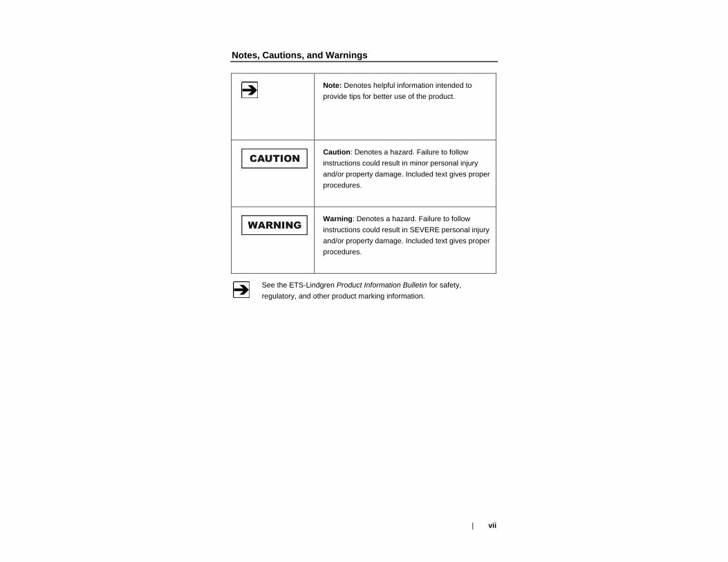
Notes, Cautions, and Warnings
Note: Denotes helpful information intended to provide tips for better use of the product.
Caution: Denotes a hazard. Failure to follow instructions could result in minor personal injury and/or property damage. Included text gives proper procedures.
Warning: Denotes a hazard. Failure to follow instructions could result in SEVERE personal injury and/or property damage. Included text gives proper procedures.
See the ETS-Lindgren Product Information Bulletin for safety, regulatory, and other product marking information.
| vii

viii |
This page intentionally left blank.
1.0 Introduction
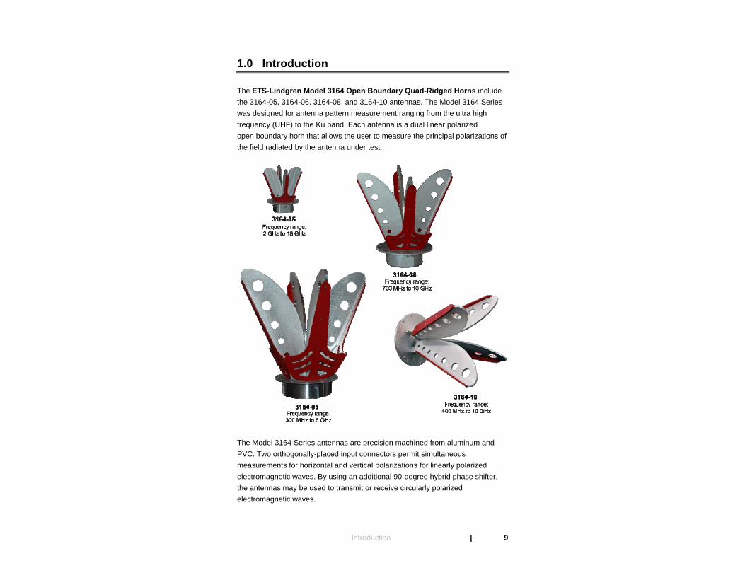
The ETS-Lindgren Model 3164 Open Boundary Quad-Ridged Horns include the 3164-05, 3164-06, 3164-08, and 3164-10 antennas. The Model 3164 Series was designed for antenna pattern measurement ranging from the ultra high frequency (UHF) to the Ku band. Each antenna is a dual linear polarized open boundary horn that allows the user to measure the principal polarizations of the field radiated by the antenna under test.
The Model 3164 Series antennas are precision machined from aluminum and PVC. Two orthogonally-placed input connectors permit simultaneous measurements for horizontal and vertical polarizations for linearly polarized electromagnetic waves. By using an additional 90-degree hybrid phase shifter, the antennas may be used to transmit or receive circularly polarized electromagnetic waves.
Introduction | 9

Testing of the Model 3164 Series shows that the isolation level between the two orthogonal test ports is better than 24 dB in the specified operating frequency range. The port isolation is the limiting factor in the cross-polarization levels of the antenna.
The Model 3164 Series antennas are designed to operate from 300 MHz to 18 GHz in a free-space environment. When the antenna is installed in a rectangular shielded anechoic chamber, the equipment under test must be at a test distance meeting the far field requirements to operate either antenna within the full frequency range.
In a quasi-free space test environment such as a tapered anechoic chamber, the Model 3164 Series antennas are ideal plane-wave transmit and receive antennas. They are ideal for use in a taper chamber over the entire range, provided it is repositioned inside the taper to obtain the optimum illumination.
The Model 3164 Series antennas ship with standard mounting hardware. For the variety of mounting options available for each antenna, see Mounting Instructions on page 23.
Model 3164-05
The 3164-05 is the smallest of the Model 3164 Series, with an operating range of 2 GHz to 18 GHz.
The 3164-05 is designed for the antenna measurement in the MW range, and covers the S, C, X, and Ku bands. It was designed as a receive antenna, but can be used as a low power radiator with a maximum continuous power handling capability of 10 W.
10 | Introduction
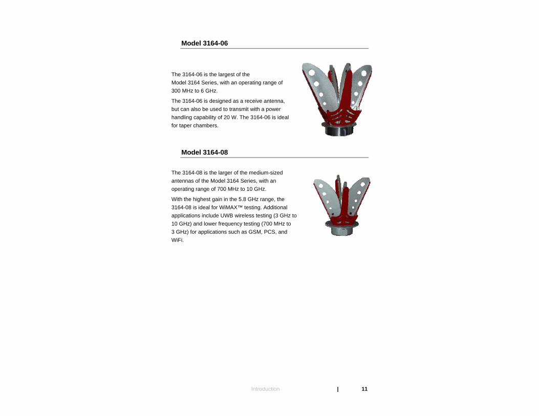
Model 3164-06
The 3164-06 is the largest of the Model 3164 Series, with an operating range of 300 MHz to 6 GHz.
The 3164-06 is designed as a receive antenna, but can also be used to transmit with a power handling capability of 20 W. The 3164-06 is ideal for taper chambers.
Model 3164-08
The 3164-08 is the larger of the medium-sized antennas of the Model 3164 Series, with an operating range of 700 MHz to 10 GHz.
With the highest gain in the 5.8 GHz range, the 3164-08 is ideal for WiMAX™ testing. Additional applications include UWB wireless testing (3 GHz to 10 GHz) and lower frequency testing (700 MHz to 3 GHz) for applications such as GSM, PCS, and WiFi.
Introduction | 11
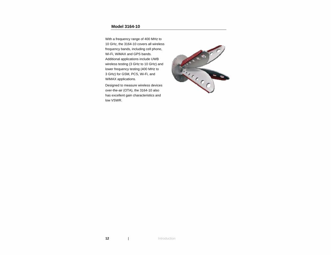
Model 3164-10
With a frequency range of 400 MHz to 10 GHz, the 3164-10 covers all wireless frequency bands, including cell phone, Wi-Fi, WiMAX and GPS bands. Additional applications include UWB wireless testing (3 GHz to 10 GHz) and lower frequency testing (400 MHz to 3 GHz) for GSM, PCS, Wi-Fi, and WiMAX applications.
Designed to measure wireless devices over-the-air (OTA), the 3164-10 also has excellent gain characteristics and low VSWR.
12 | Introduction

7-TR Tripod
ETS-Lindgren offers the 7-TR Tripod for use at both indoor and outdoor EMC test sites.
• Non-metallic and non-reflective.
• Constructed of PVC and fiberglass components, providing increased stability for physically large antennas.
• Unique design allows for quick assembly, disassembly, and convenient storage.
• Allows several different configurations, including options for manual or pneumatic polarization.
• Quick height adjustment and locking wheels provide ease of use during testing.
• Maximum height is 2.17 m (85.8 in), with a minimum height of 0.8 m (31.8 in). Can support a 13.5 kg (30 lb) load.
ETS-Lindgren Product Information Bulletin
See the ETS-Lindgren Product Information Bulletin included with your shipment for the following:
• Warranty information
• Safety, regulatory, and other product marking information
• Steps to receive your shipment
• Steps to return a component for service
• ETS-Lindgren calibration service
• ETS-Lindgren contact information
Introduction | 13

This page intentionally left blank.
14 | Introduction
2.0 Maintenance
Before performing any maintenance, follow the safety information in the ETS-Lindgren Product Information Bulletin included with your shipment.
Maintenance of the Model 3164 Series is limited to external components such as cables or connectors.
If you have any questions concerning maintenance, contact ETS-Lindgren Customer Service.
WARRANTY
Annual Calibration
See the Product Information Bulletin included with your shipment for information on ETS-Lindgren calibration services.
Maintenance | 15
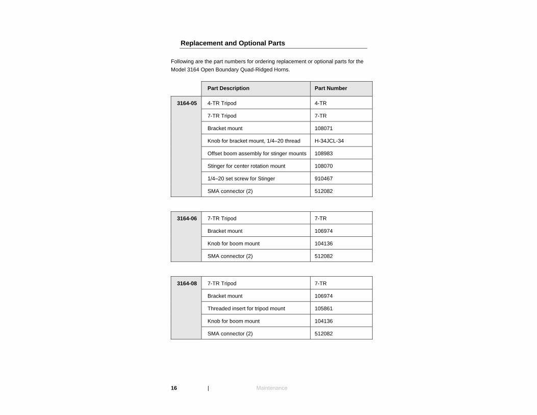
Replacement and Optional Parts
Following are the part numbers for ordering replacement or optional parts for the Model 3164 Open Boundary Quad-Ridged Horns.
Part Description Part Number
3164-05 4-TR Tripod 4-TR
7-TR Tripod 7-TR
Bracket mount 108071
Knob for bracket mount, 1/4–20 thread H-34JCL-34
Offset boom assembly for stinger mounts 108983
Stinger for center rotation mount 108070
1/4–20 set screw for Stinger 910467
SMA connector (2) 512082
3164-06 7-TR Tripod 7-TR
Bracket mount 106974
Knob for boom mount 104136
SMA connector (2) 512082
3164-08 7-TR Tripod 7-TR
Bracket mount 106974
Threaded insert for tripod mount 105861
Knob for boom mount 104136
SMA connector (2) 512082
16 | Maintenance
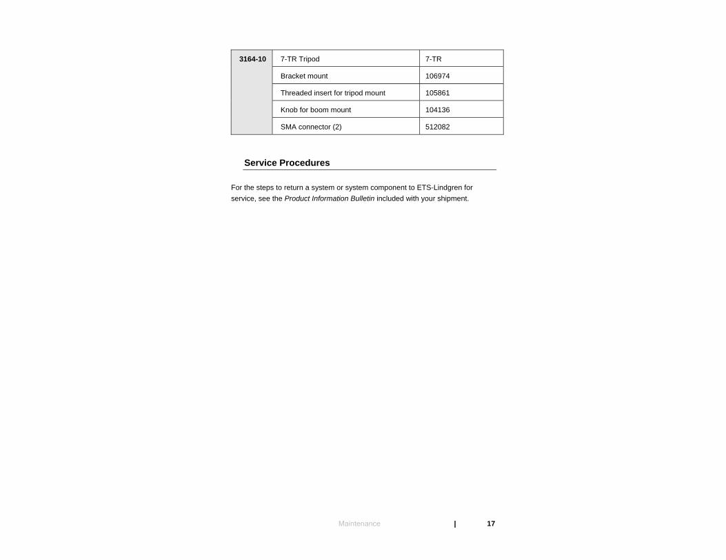
3164-10 7-TR Tripod 7-TR
Bracket mount 106974
Threaded insert for tripod mount 105861
Knob for boom mount 104136
SMA connector (2) 512082
Service Procedures
For the steps to return a system or system component to ETS-Lindgren for service, see the Product Information Bulletin included with your shipment.
Maintenance | 17

This page intentionally left blank.
18 | Maintenance
3.0 Specifications
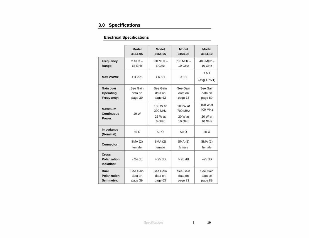
Electrical Specifications
Model
3164-05 Model
3164-06 Model
3164-08 Model
3164-10
Frequency Range:
2 GHz – 18 GHz
300 MHz –6 GHz
700 MHz – 10 GHz
400 MHz –10 GHz
Max VSWR: < 3.25:1 < 6.5:1 < 3:1 < 5:1
(Avg 1.75:1)
Gain over Operating Frequency:
See Gain data on page 39
See Gain data on page 63
See Gain data on page 73
See Gain data on page 89
Maximum Continuous Power:
10 W
150 W at 300 MHz
25 W at 6 GHz
100 W at 700 MHz
20 W at 10 GHz
100 W at 400 MHz
20 W at 10 GHz
Impedance (Nominal):
50 Ω 50 Ω 50 Ω 50 Ω
Connector: SMA (2)
female
SMA (2)
female
SMA (2)
female
SMA (2)
female
Cross Polarization Isolation:
> 24 dB > 25 dB > 20 dB –25 dB
Dual Polarization Symmetry:
See Gain data on page 39
See Gain data on page 63
See Gain data on page 73
See Gain data on page 89
Specifications | 19
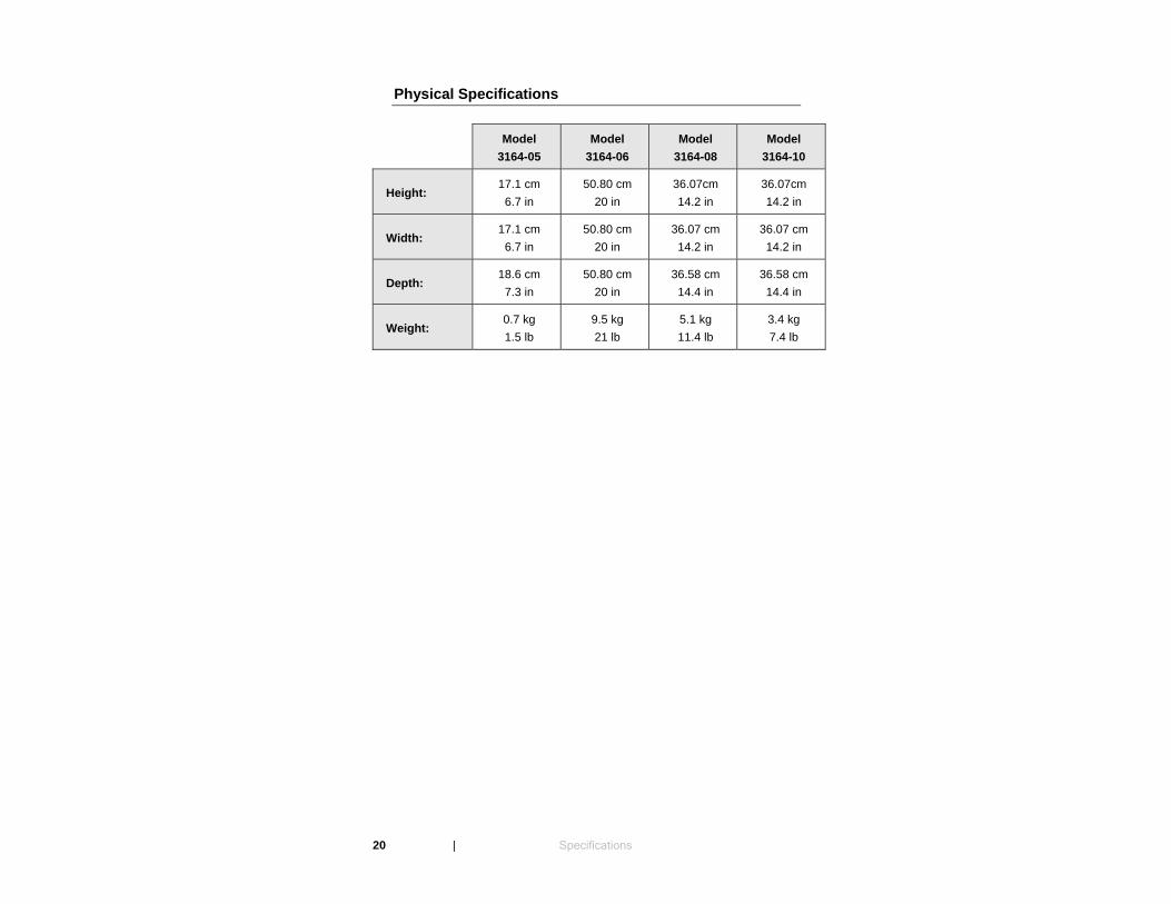
Physical Specifications
Model
3164-05 Model
3164-06 Model
3164-08 Model
3164-10
Height: 17.1 cm 6.7 in
50.80 cm 20 in
36.07cm 14.2 in
36.07cm 14.2 in
Width: 17.1 cm 6.7 in
50.80 cm 20 in
36.07 cm 14.2 in
36.07 cm 14.2 in
Depth: 18.6 cm 7.3 in
50.80 cm 20 in
36.58 cm 14.4 in
36.58 cm 14.4 in
Weight: 0.7 kg 1.5 lb
9.5 kg 21 lb
5.1 kg 11.4 lb
3.4 kg 7.4 lb
20 | Specifications
4.0 Application
The Model 3164 Open Boundary Quad-Ridged Horns can be used as transmit or receive antennas for measuring all wireless telecommunications devices, such as cell phones and Internet devices. Additionally, the antennas cover most of the common radar and MW bands used in military applications.
When an antenna is configured for receive mode, it can be used to measure far field antenna patterns for the two orthogonal polarizations simultaneously. When an antenna is configured for transmit mode, it can be used to transmit signals from a base station simulator. Many intrinsic RF properties of wireless handsets can be measured at these two configurations. The user may also configure the same system to measure the RF interaction between a wireless handset and the operator.
The Model 3164 Series can also be configured to transmit or receive circularly polarized signals for testing antennas or receiving devices for Global Positioning Systems.
Application | 21

This page intentionally left blank.
22 | Application
5.0 Mounting Instructions
The Model 3164 Series antennas are precision measurement devices. Handle your antenna with care.
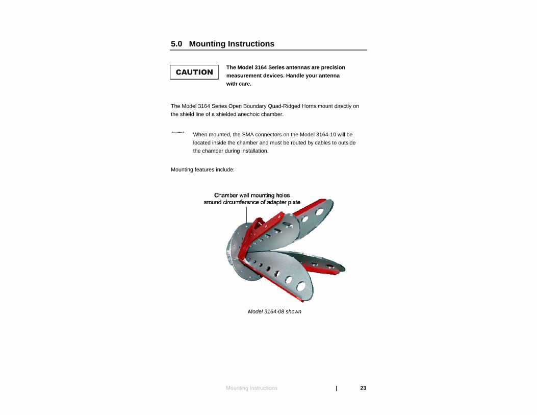
The Model 3164 Series Open Boundary Quad-Ridged Horns mount directly on the shield line of a shielded anechoic chamber.
When mounted, the SMA connectors on the Model 3164-10 will be located inside the chamber and must be routed by cables to outside the chamber during installation.
Mounting features include:
Model 3164-08 shown
Mounting Instructions | 23

• Chamber wall mounting holes—Equidistant holes around the
circumference of the adapter plate accept 1/4–20 thread screws and nuts for mounting to a chamber wall.
• Easy access to SMA connectors—The circular mounting plate provides the primary interface to the shielded enclosure mount panel. By fastening the mounting plate to the shielded enclosure, the two SMA connectors are on the outside of the enclosure, providing easy access. This also puts the cables outside of the enclosure, which reduces the effect of the cables on the measurement.
• Security of shielding integrity—The back end of the antenna is machined of a single aluminum block, so the shielding effectiveness of the enclosure is not compromised by installation. This unique feature eliminates the need for a transmit antenna positioning device or a walk path inside the shielded anechoic chamber, both of which could present unwanted reflections of shielded anechoic chambers when installed improperly.
• Maximize test range distance—The integrated mount fixture allows maximizing of the test range distance for a shielded anechoic chamber of defined dimensions.
24 | Mounting Instructions
Mounting Illustrations for 3164-05
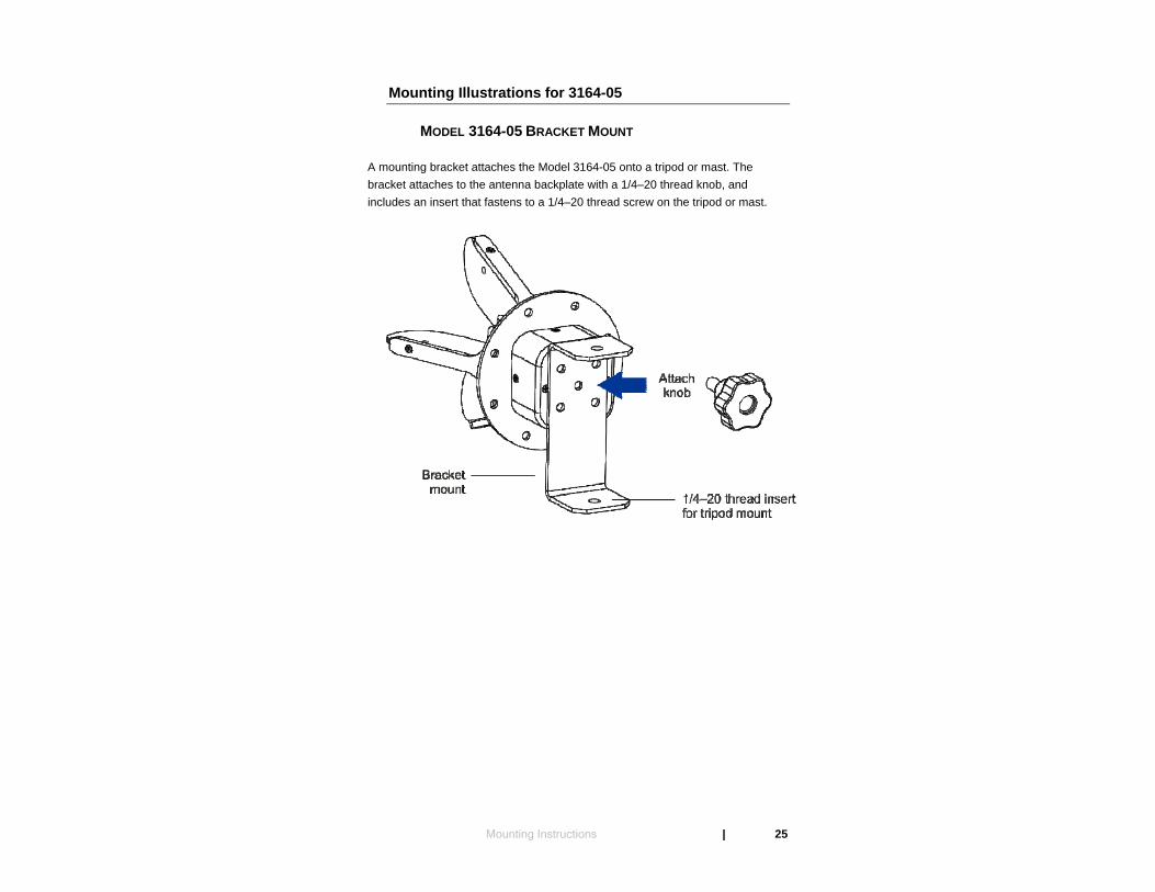
MODEL 3164-05 BRACKET MOUNT
A mounting bracket attaches the Model 3164-05 onto a tripod or mast. The bracket attaches to the antenna backplate with a 1/4–20 thread knob, and includes an insert that fastens to a 1/4–20 thread screw on the tripod or mast.
Mounting Instructions | 25
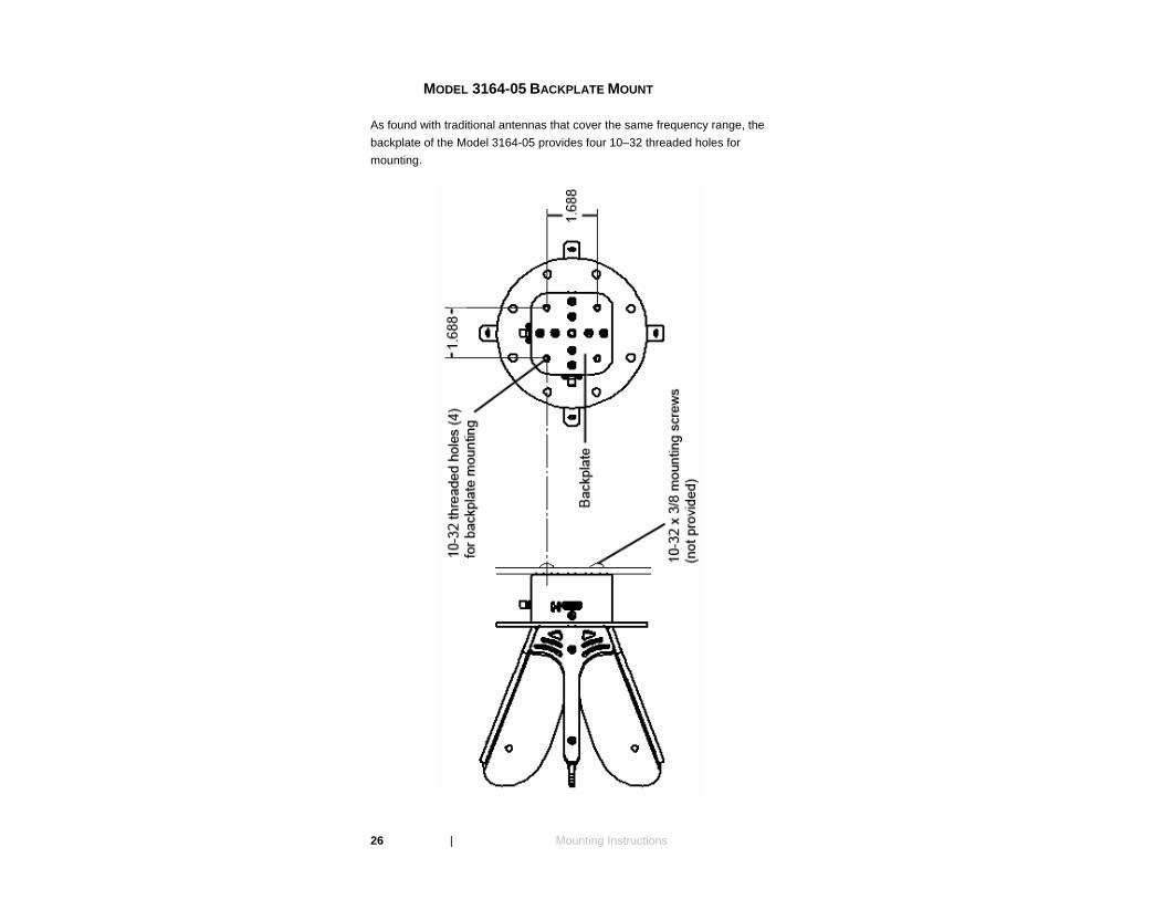
MODEL 3164-05 BACKPLATE MOUNT
As found with traditional antennas that cover the same frequency range, the backplate of the Model 3164-05 provides four 10–32 threaded holes for mounting.
26 | Mounting Instructions
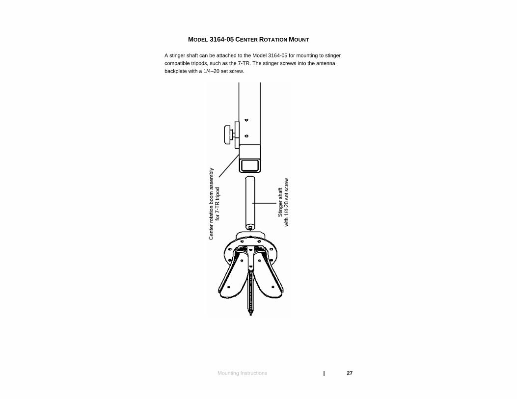
MODEL 3164-05 CENTER ROTATION MOUNT
A stinger shaft can be attached to the Model 3164-05 for mounting to stinger compatible tripods, such as the 7-TR. The stinger screws into the antenna backplate with a 1/4–20 set screw.
Mounting Instructions | 27

MODEL 3164-05 CHAMBER WALL MOUNT
The Model 3164-05 provides eight equidistant holes around the circumference of the adapter plate of the antenna. These holes accept 1/4–20 thread screws and nuts for mounting to a chamber wall.
28 | Mounting Instructions
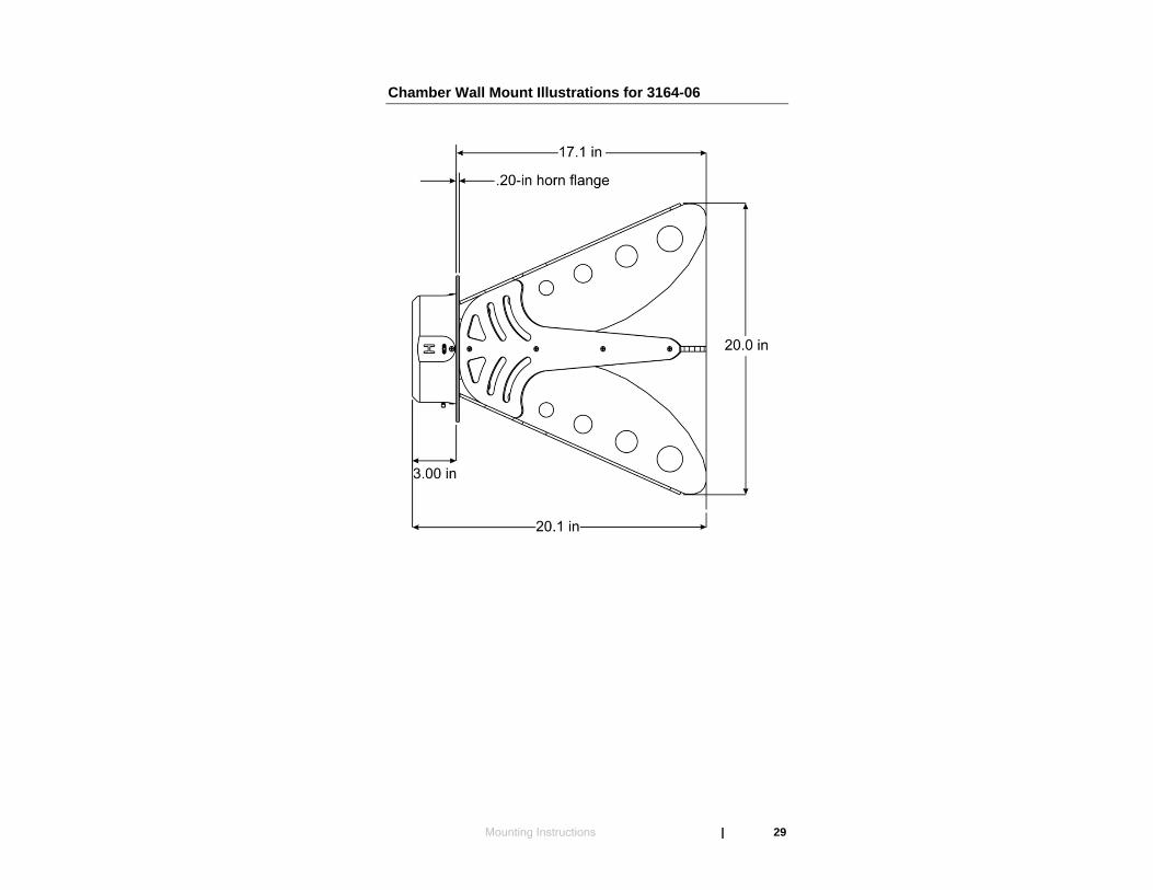
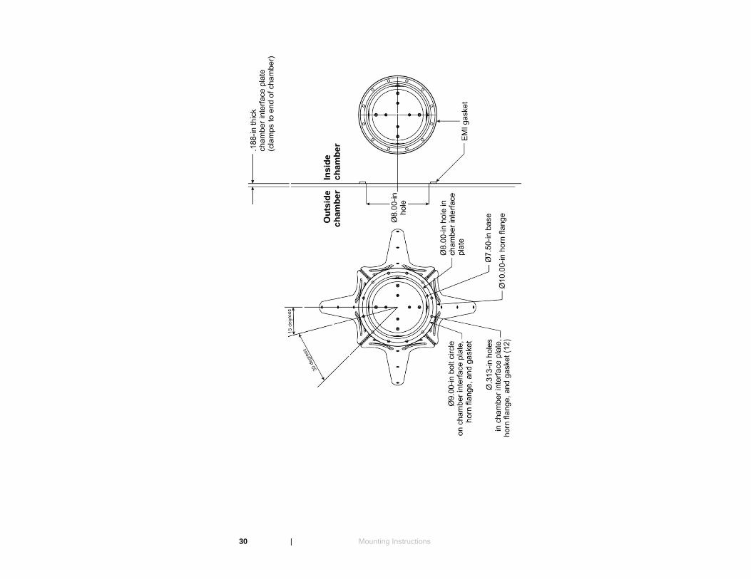
Chamber Wall Mount Illustrations for 3164-06
Mounting Instructions | 29
30 | Mounting Instructions
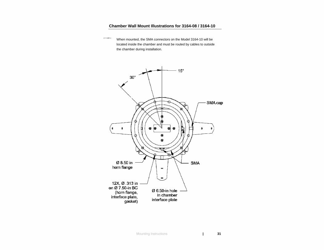
Chamber Wall Mount Illustrations for 3164-08 / 3164-10
When mounted, the SMA connectors on the Model 3164-10 will be located inside the chamber and must be routed by cables to outside the chamber during installation.
Mounting Instructions | 31

32 | Mounting Instructions
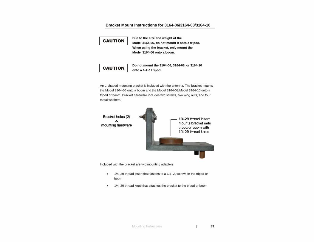
Bracket Mount Instructions for 3164-06/3164-08/3164-10
Due to the size and weight of the Model 3164-06, do not mount it onto a tripod. When using the bracket, only mount the Model 3164-06 onto a boom.
Do not mount the 3164-06, 3164-08, or 3164-10 onto a 4-TR Tripod.
An L-shaped mounting bracket is included with the antenna. The bracket mounts the Model 3164-06 onto a boom and the Model 3164-08/Model 3164-10 onto a tripod or boom. Bracket hardware includes two screws, two wing nuts, and four metal washers.
Included with the bracket are two mounting adapters:
• 1/4–20 thread insert that fastens to a 1/4–20 screw on the tripod or boom
• 1/4–20 thread knob that attaches the bracket to the tripod or boom
Mounting Instructions | 33
34 | Mounting Instructions

To attach the mounting bracket:
1. Place the antenna in a stable position and location to prevent it from falling or rolling while attaching the bracket.
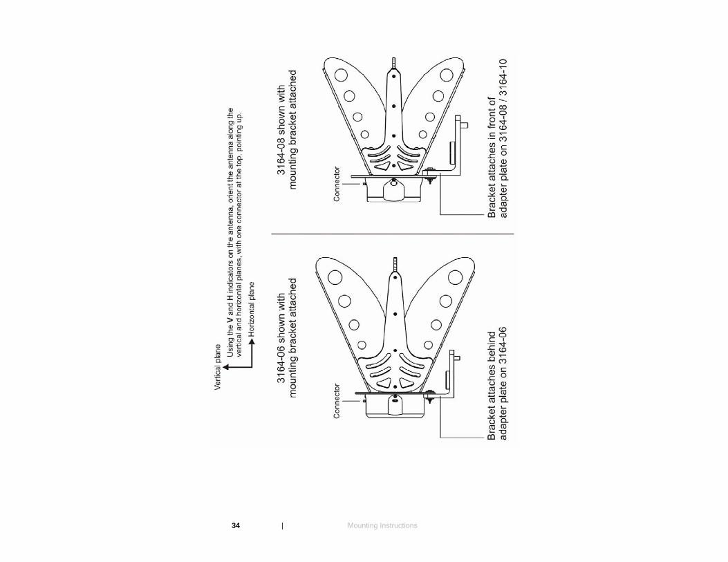
2. Orient the antenna: Using the V (vertical) and H (horizontal) marks on the antenna, orient the antenna along the vertical and horizontal planes with one connector at the top, pointing up.
3. With the antenna oriented, align the two bracket holes in the mounting bracket with the two lowest screw holes in the antenna adapter plate.
• For Model 3164-06, align the mounting bracket on the back of the adapter plate.
• For Model 3164-08 / 3164-10, align the mounting bracket on the front of the adapter plate.
Mounting Instructions | 35

4. Thread a washer onto a screw. From the front of the antenna adapter
plate, insert the screw and washer through one of the bracket holes.
5. On the back of the mounting bracket, thread a washer onto the screw, and then tighten a wing nut onto the screw.
6. Repeat for the remaining bracket hole.
Summary of Mounting Options
4-TR MOUNTING
Do not mount the 3164-06, 3164-08, or 3164-10 onto a 4-TR Tripod.
Only the Model 3164-05 can be mounted to a 4-TR. See Mounting Illustrations for 3164-05 on page 25 for more information.
36 | Mounting Instructions
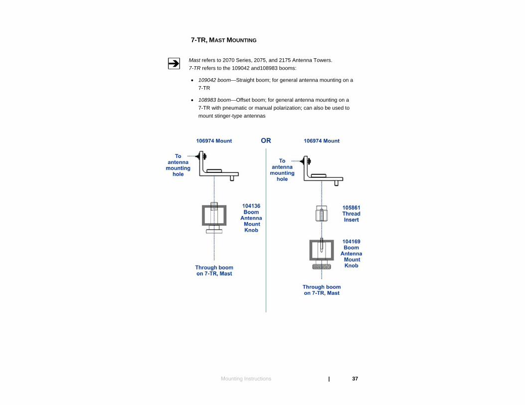
7-TR, MAST MOUNTING
Mast refers to 2070 Series, 2075, and 2175 Antenna Towers. 7-TR refers to the 109042 and108983 booms:
• 109042 boom—Straight boom; for general antenna mounting on a 7-TR
• 108983 boom—Offset boom; for general antenna mounting on a 7-TR with pneumatic or manual polarization; can also be used to mount stinger-type antennas
Mounting Instructions | 37
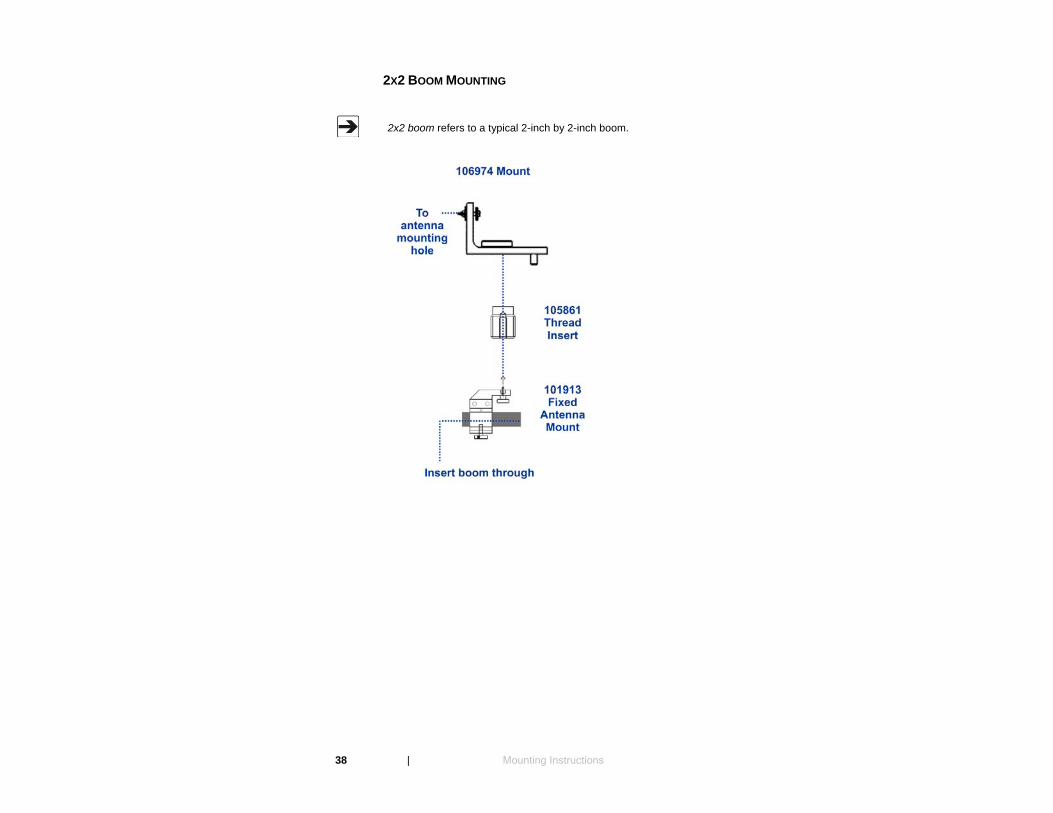
2X2 BOOM MOUNTING
2x2 boom refers to a typical 2-inch by 2-inch boom.
38 | Mounting Instructions
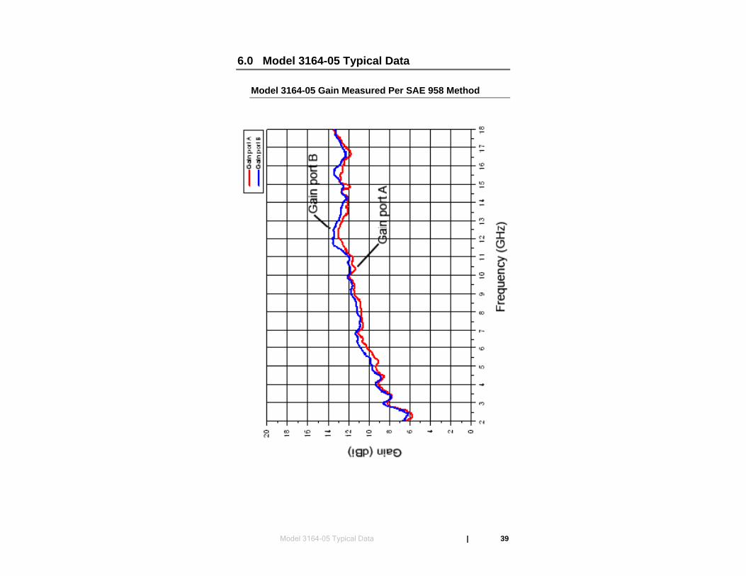
6.0 Model 3164-05 Typical Data
Model 3164-05 Gain Measured Per SAE 958 Method
Model 3164-05 Typical Data | 39
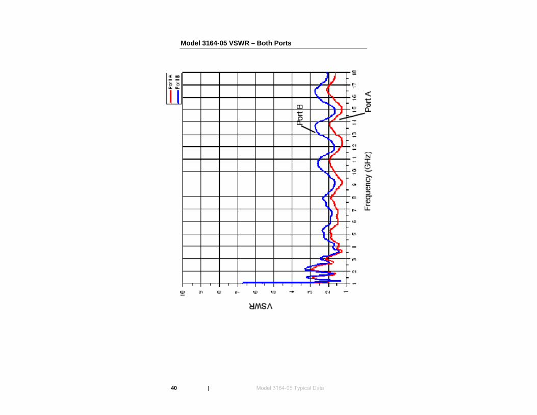
Model 3164-05 VSWR – Both Ports
40 | Model 3164-05 Typical Data
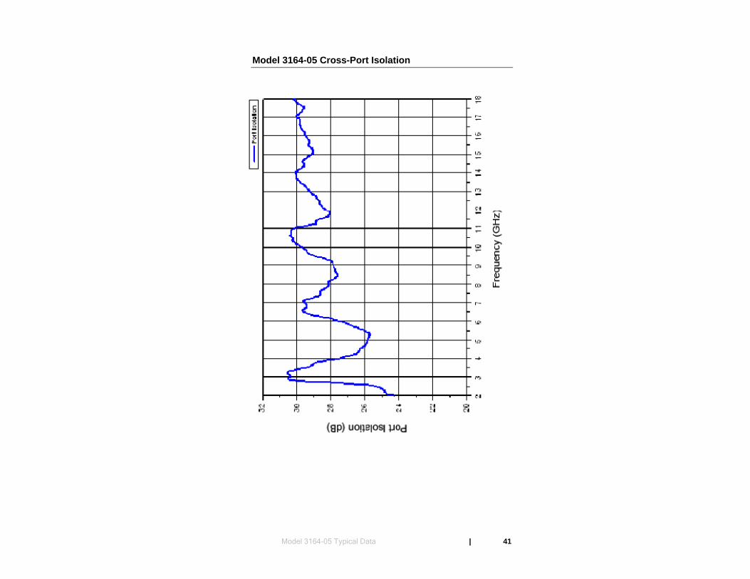
Model 3164-05 Cross-Port Isolation
Model 3164-05 Typical Data | 41
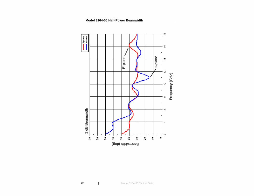
Model 3164-05 Half-Power Beamwidth
42 | Model 3164-05 Typical Data
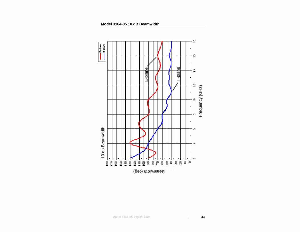
Model 3164-05 10 dB Beamwidth
Model 3164-05 Typical Data | 43

This page intentionally left blank.
44 | Model 3164-05 Typical Data

7.0 Model 3164-05 Typical Radiation Patterns
Model 3164-05 at 2 GHz
Model 3164-05 Typical Radiation Patterns | 45

Model 3164 05 at 3 GHz
46 | Model 3164-05 Typical Radiation Patterns

Model 3164-05 at 4 GHz
Model 3164-05 Typical Radiation Patterns | 47
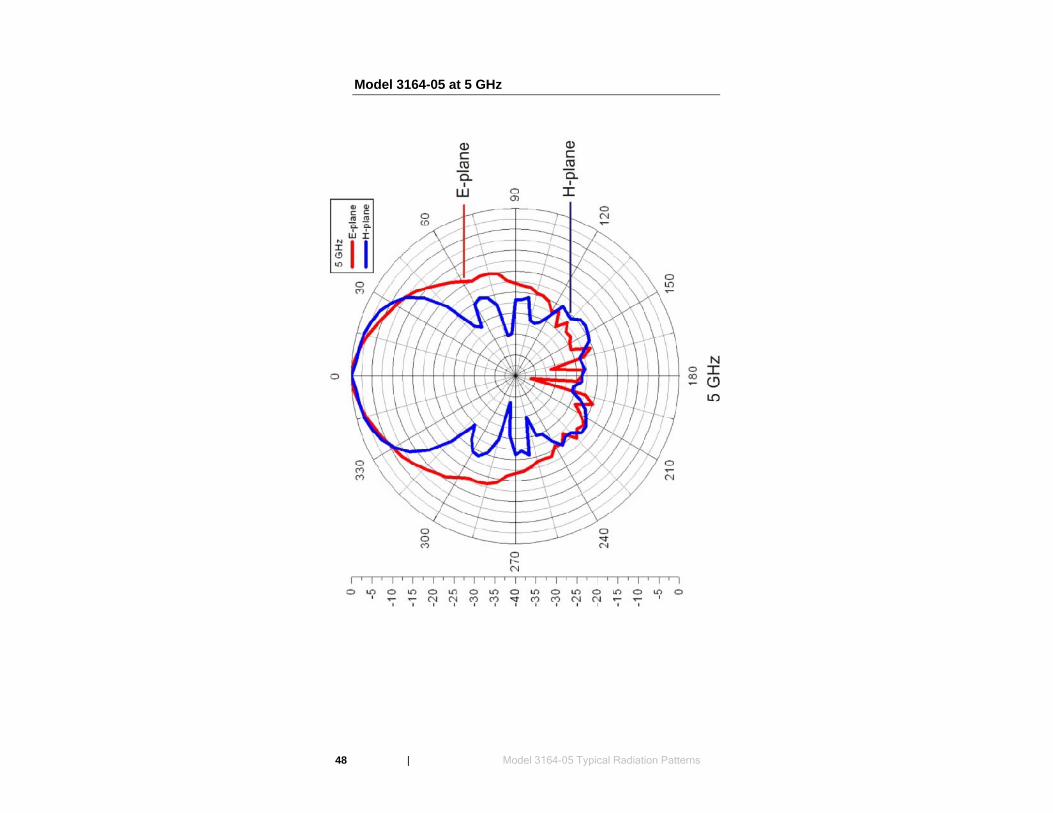
Model 3164-05 at 5 GHz
48 | Model 3164-05 Typical Radiation Patterns
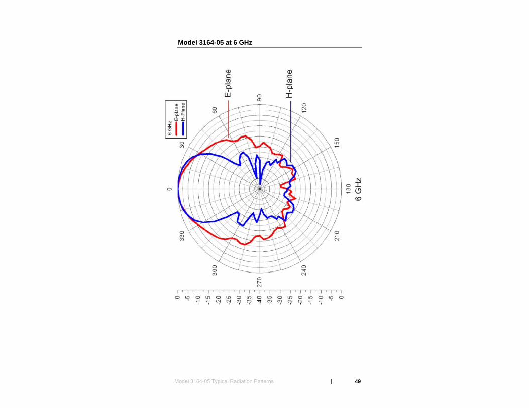
Model 3164-05 at 6 GHz
Model 3164-05 Typical Radiation Patterns | 49
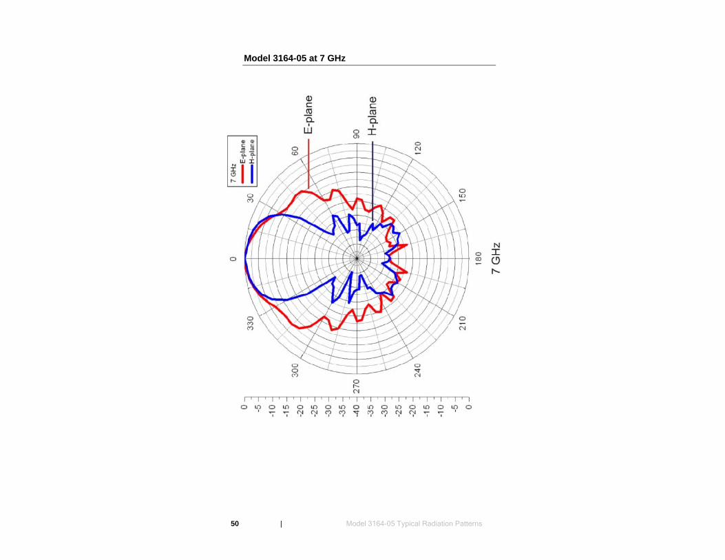
Model 3164-05 at 7 GHz
50 | Model 3164-05 Typical Radiation Patterns
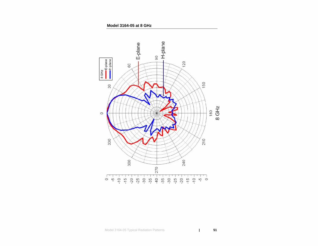
Model 3164-05 at 8 GHz
Model 3164-05 Typical Radiation Patterns | 51

Model 3164-05 at 9 GHz
52 | Model 3164-05 Typical Radiation Patterns
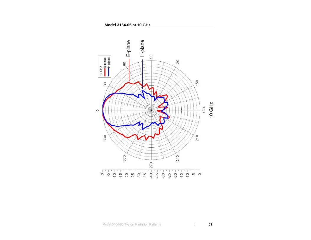
Model 3164-05 at 10 GHz
Model 3164-05 Typical Radiation Patterns | 53

Model 3164-05 at 11 GHz
54 | Model 3164-05 Typical Radiation Patterns
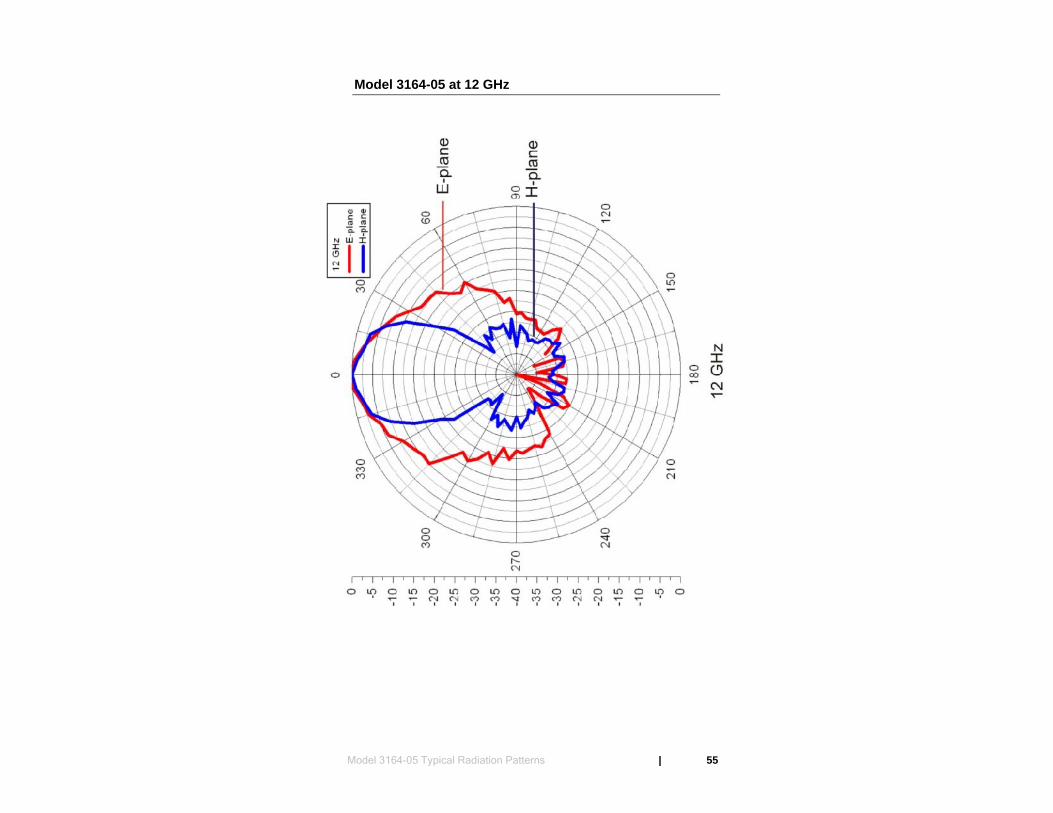
Model 3164-05 at 12 GHz
Model 3164-05 Typical Radiation Patterns | 55
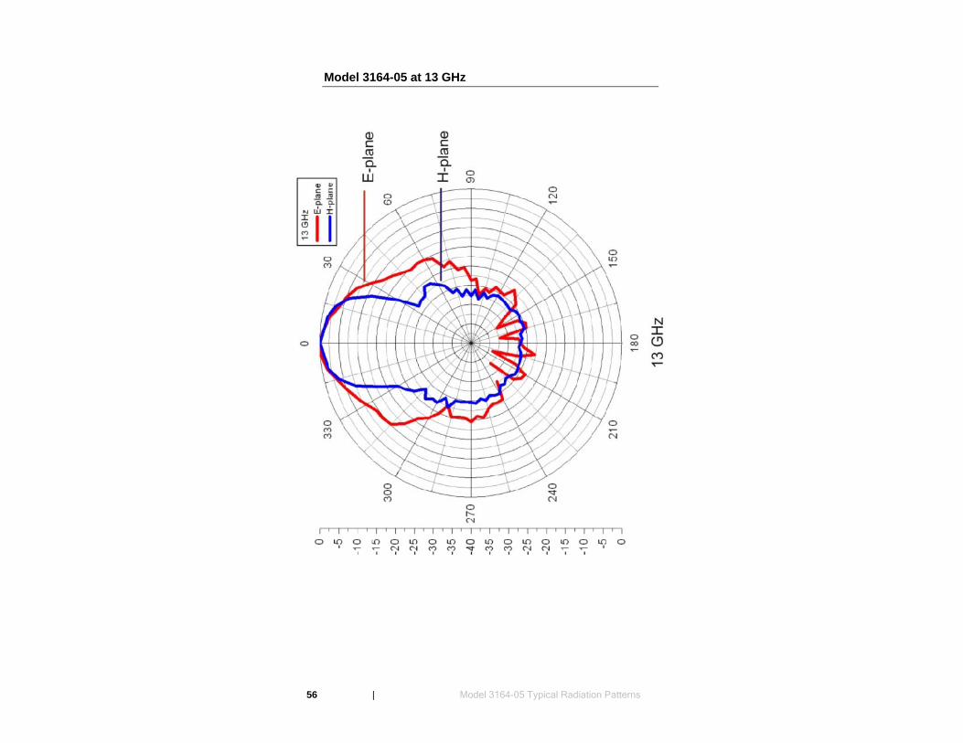
Model 3164-05 at 13 GHz
56 | Model 3164-05 Typical Radiation Patterns
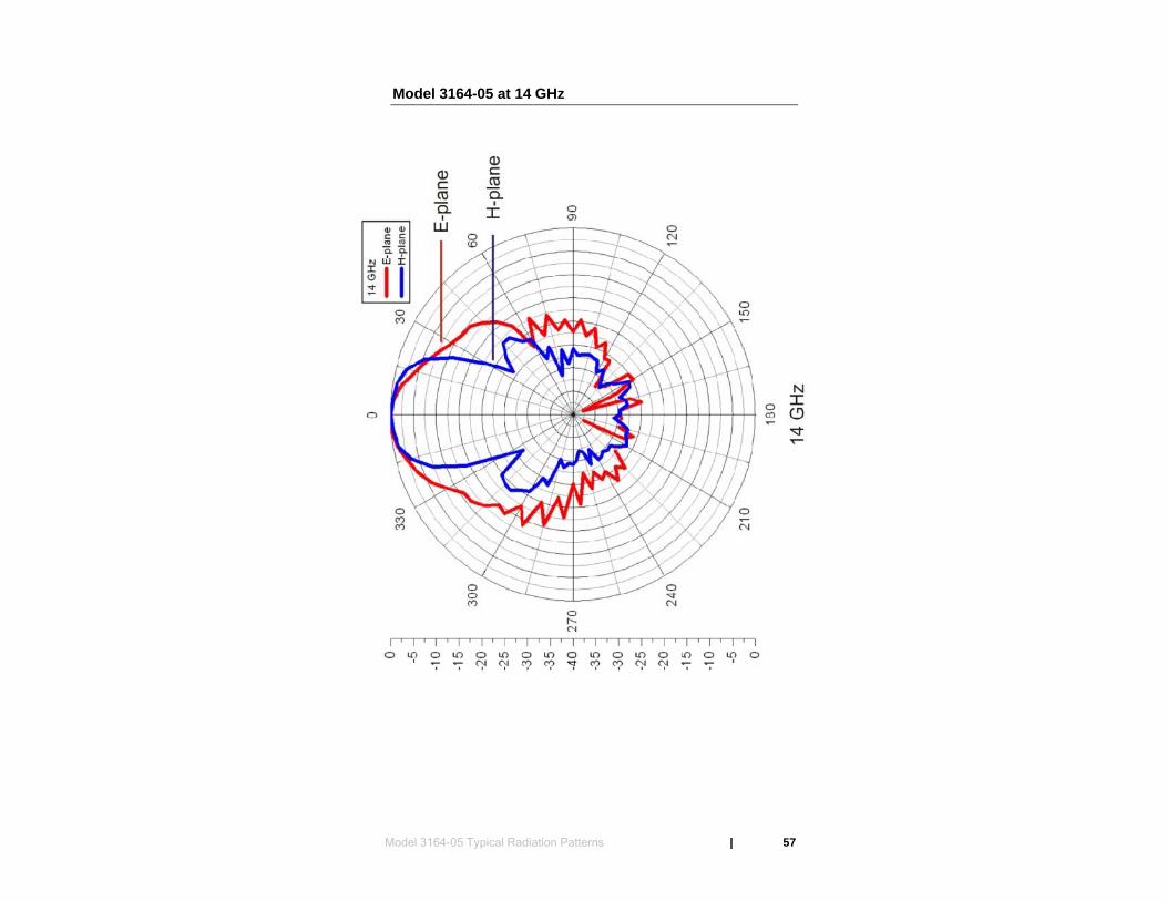
Model 3164-05 at 14 GHz
Model 3164-05 Typical Radiation Patterns | 57
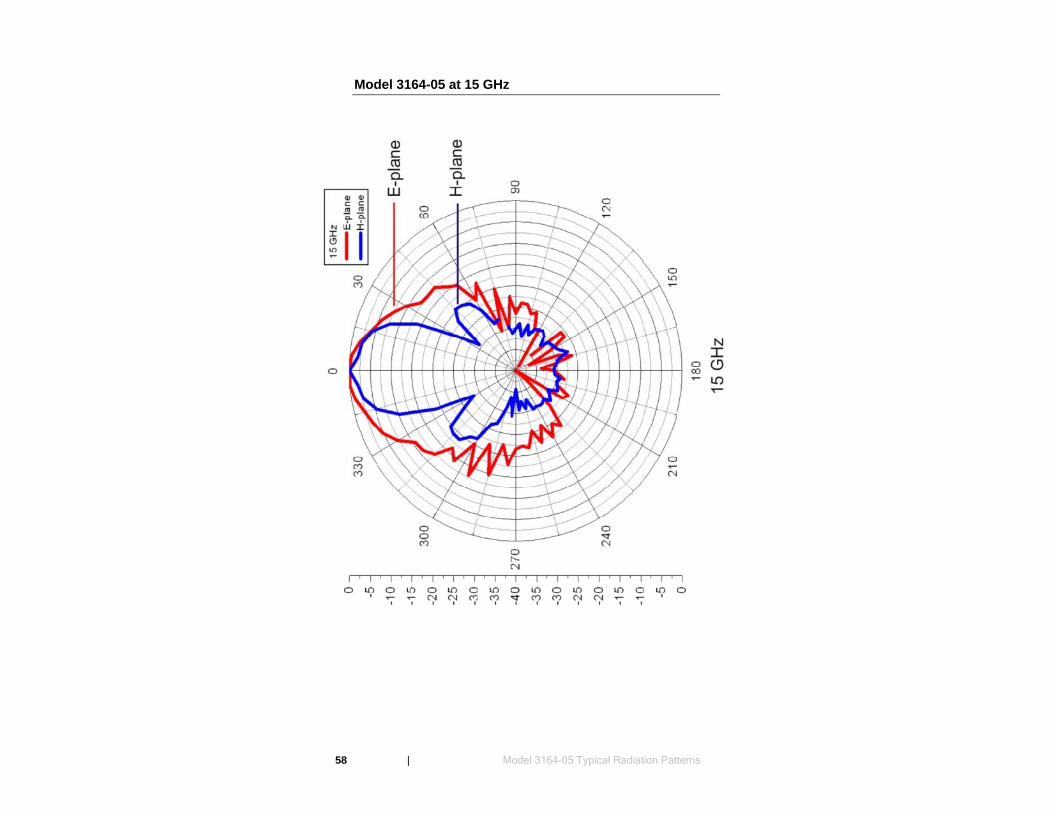
Model 3164-05 at 15 GHz
58 | Model 3164-05 Typical Radiation Patterns
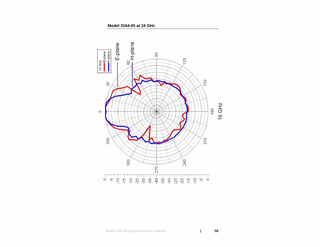
Model 3164-05 at 16 GHz
Model 3164-05 Typical Radiation Patterns | 59
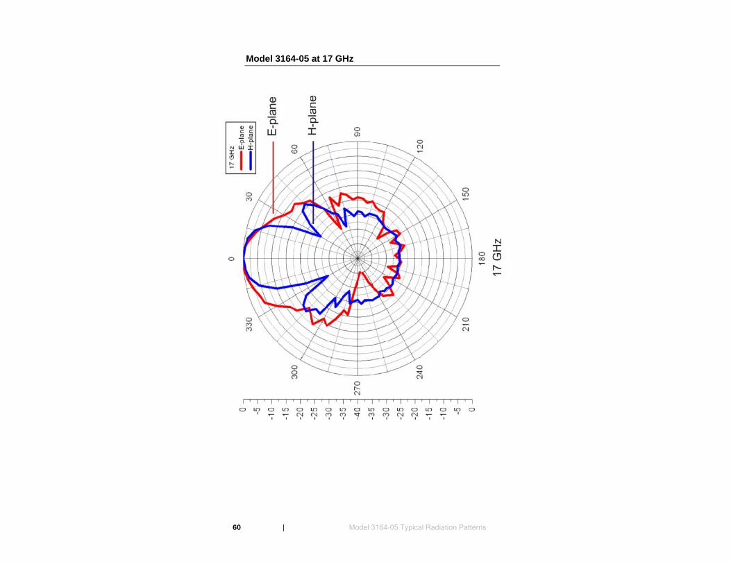
Model 3164-05 at 17 GHz
60 | Model 3164-05 Typical Radiation Patterns
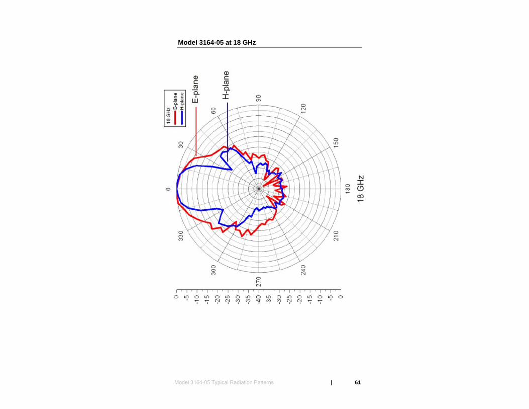
Model 3164-05 at 18 GHz
Model 3164-05 Typical Radiation Patterns | 61

This page intentionally left blank.
62 | Model 3164-05 Typical Radiation Patterns

8.0 Model 3164-06 Typical Data
Model 3164-06 Gain
Model 3164-06 Typical Data | 63
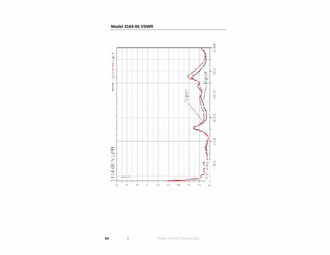
Model 3164-06 VSWR
64 | Model 3164-06 Typical Data
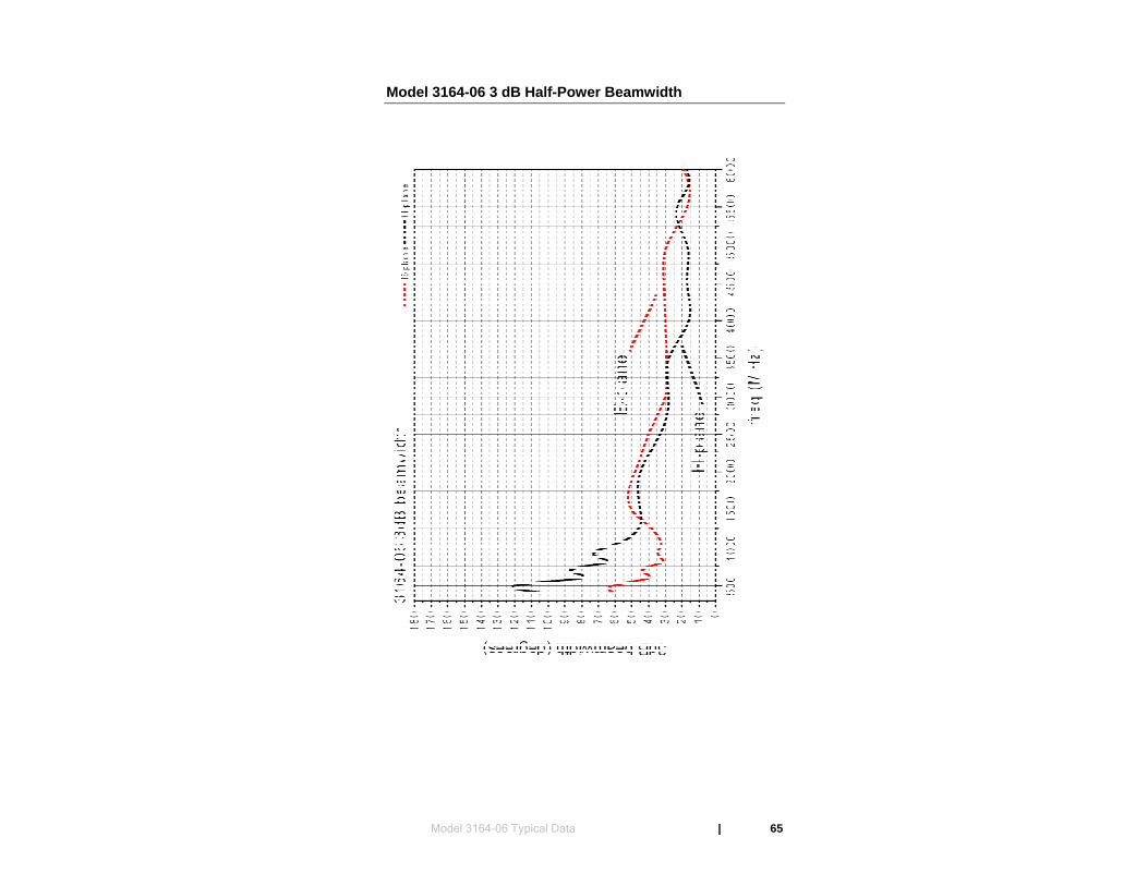
Model 3164-06 3 dB Half-Power Beamwidth
Model 3164-06 Typical Data | 65
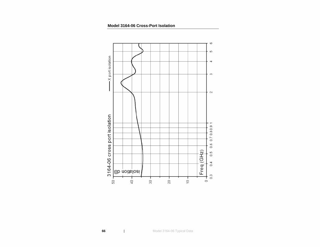
Model 3164-06 Cross-Port Isolation
66 | Model 3164-06 Typical Data

9.0 Model 3164-06 Typical Radiation Patterns
Model 3164-06 at 400 MHz–600 MHz
Model 3164-06 Typical Radiation Patterns | 67
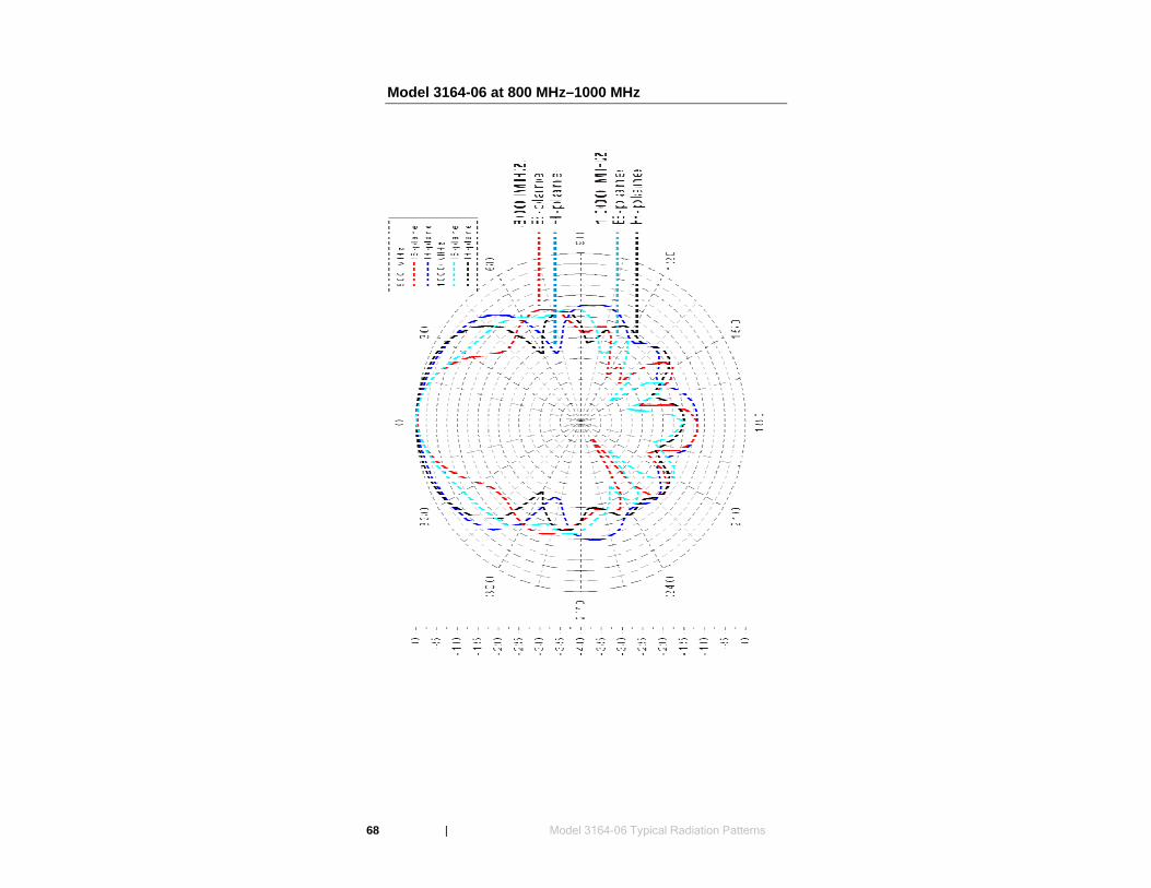
Model 3164-06 at 800 MHz–1000 MHz
68 | Model 3164-06 Typical Radiation Patterns
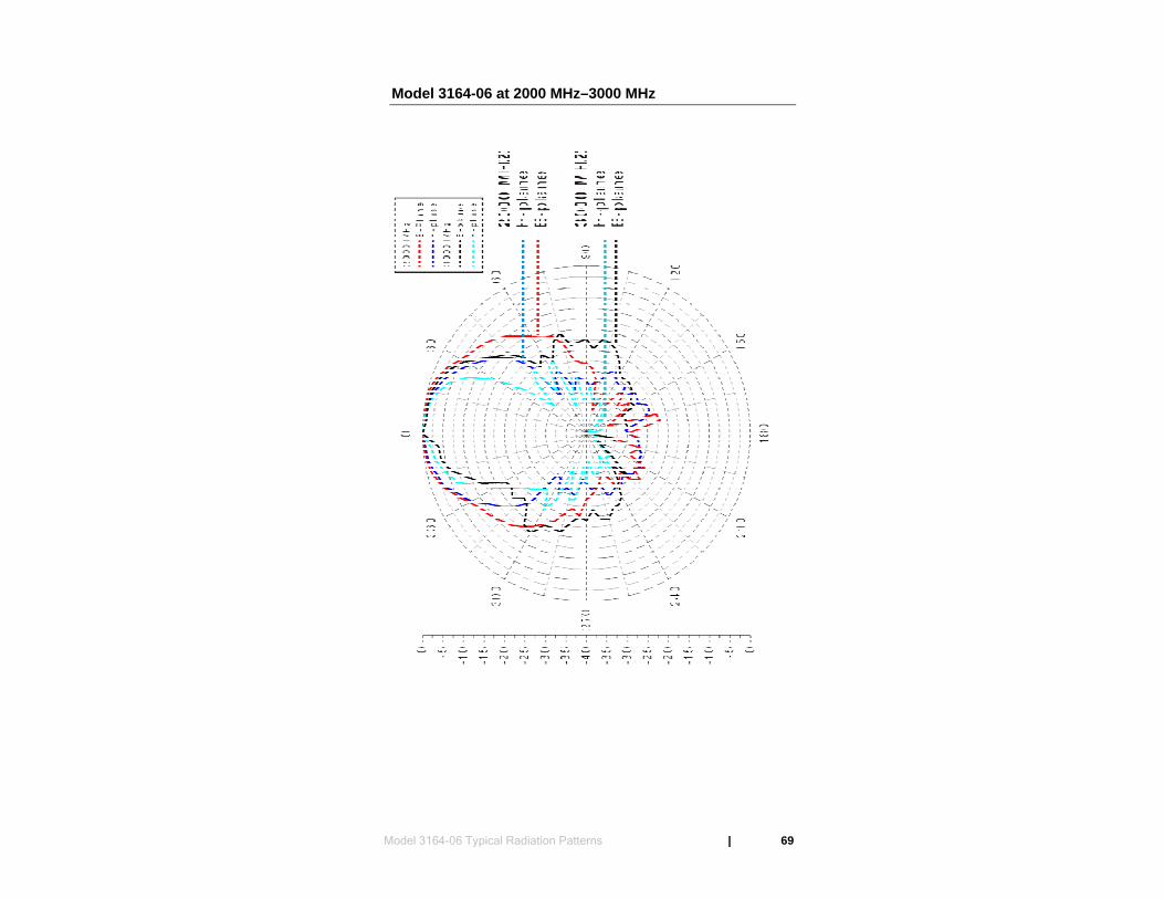
Model 3164-06 at 2000 MHz–3000 MHz
Model 3164-06 Typical Radiation Patterns | 69
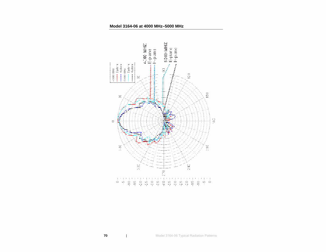
Model 3164-06 at 4000 MHz–5000 MHz
70 | Model 3164-06 Typical Radiation Patterns
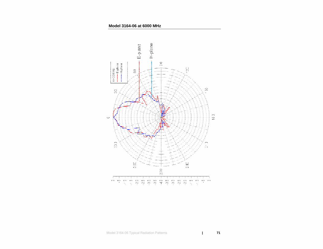
Model 3164-06 at 6000 MHz
Model 3164-06 Typical Radiation Patterns | 71

This page intentionally left blank.
72 | Model 3164-06 Typical Radiation Patterns
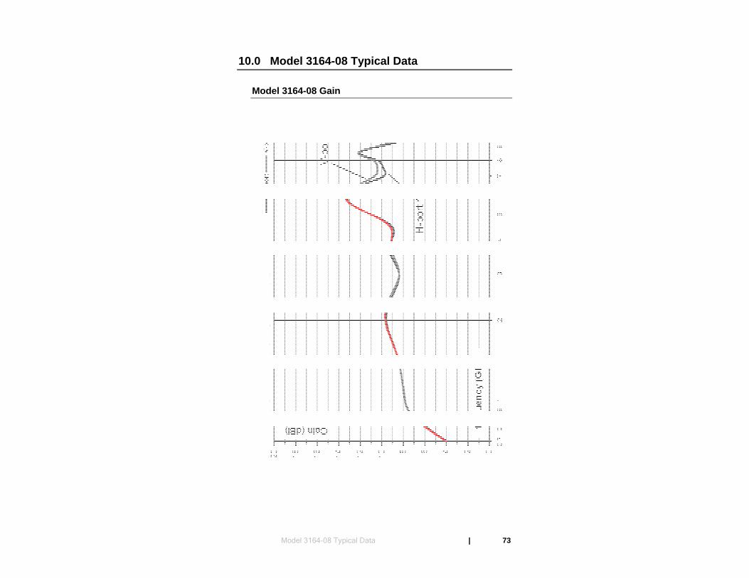
10.0 Model 3164-08 Typical Data
Model 3164-08 Gain
Model 3164-08 Typical Data | 73
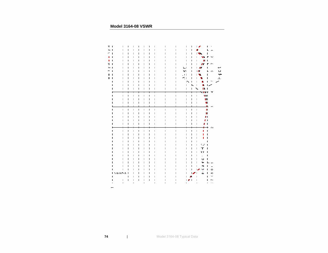
Model 3164-08 VSWR
74 | Model 3164-08 Typical Data
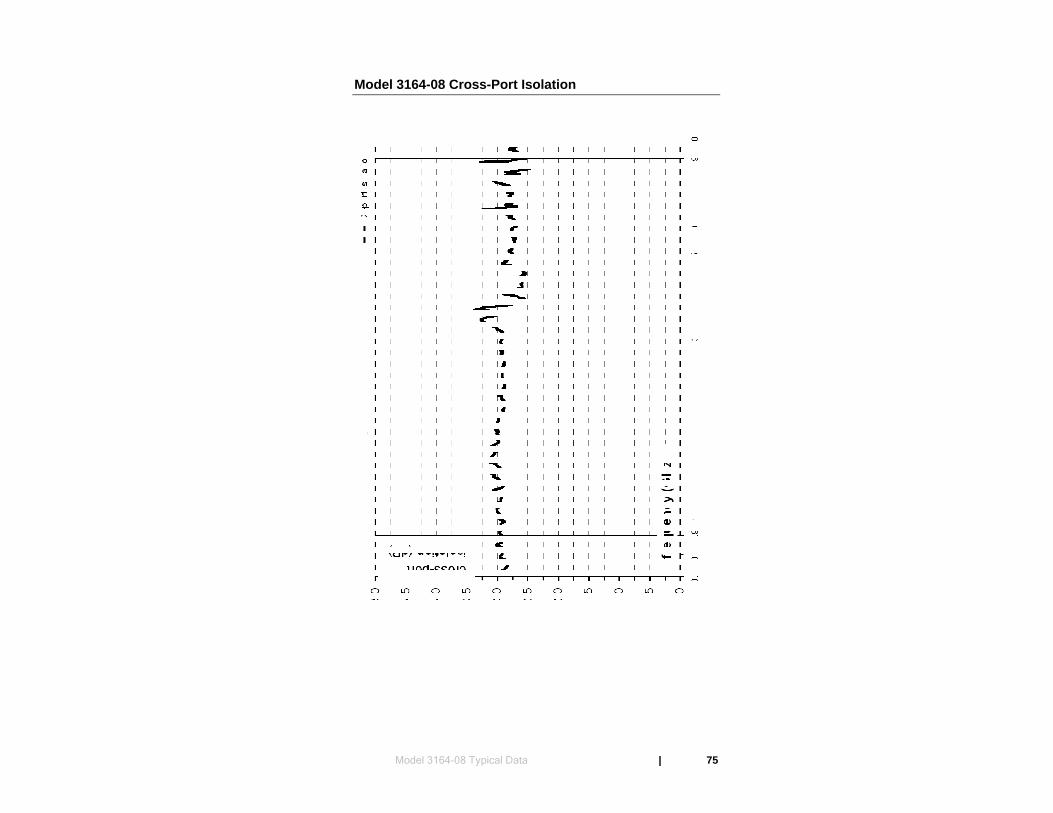
Model 3164-08 Cross-Port Isolation
Model 3164-08 Typical Data | 75

This page intentionally left blank.
76 | Model 3164-08 Typical Data
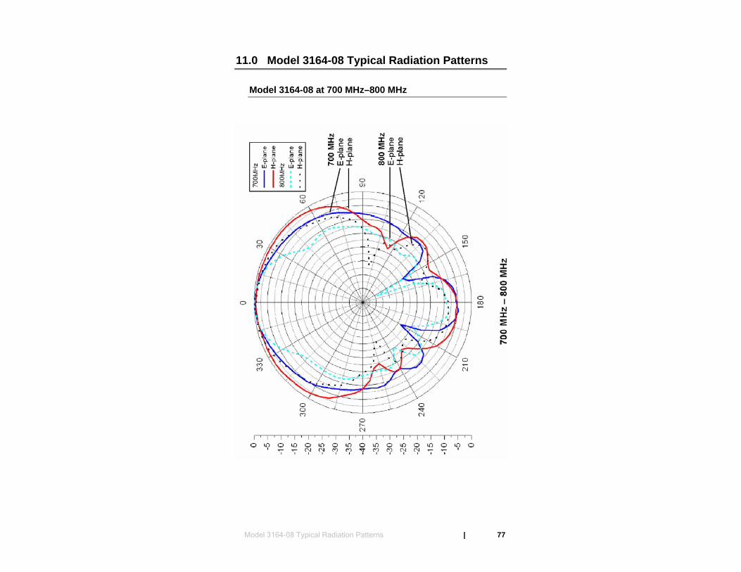
11.0 Model 3164-08 Typical Radiation Patterns
Model 3164-08 at 700 MHz–800 MHz
Model 3164-08 Typical Radiation Patterns | 77
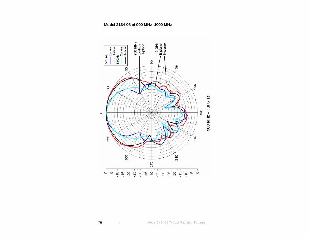
Model 3164-08 at 900 MHz–1000 MHz
78 | Model 3164-08 Typical Radiation Patterns

Model 3164-08 at 1.5 GHz–2.0 GHz
Model 3164-08 Typical Radiation Patterns | 79
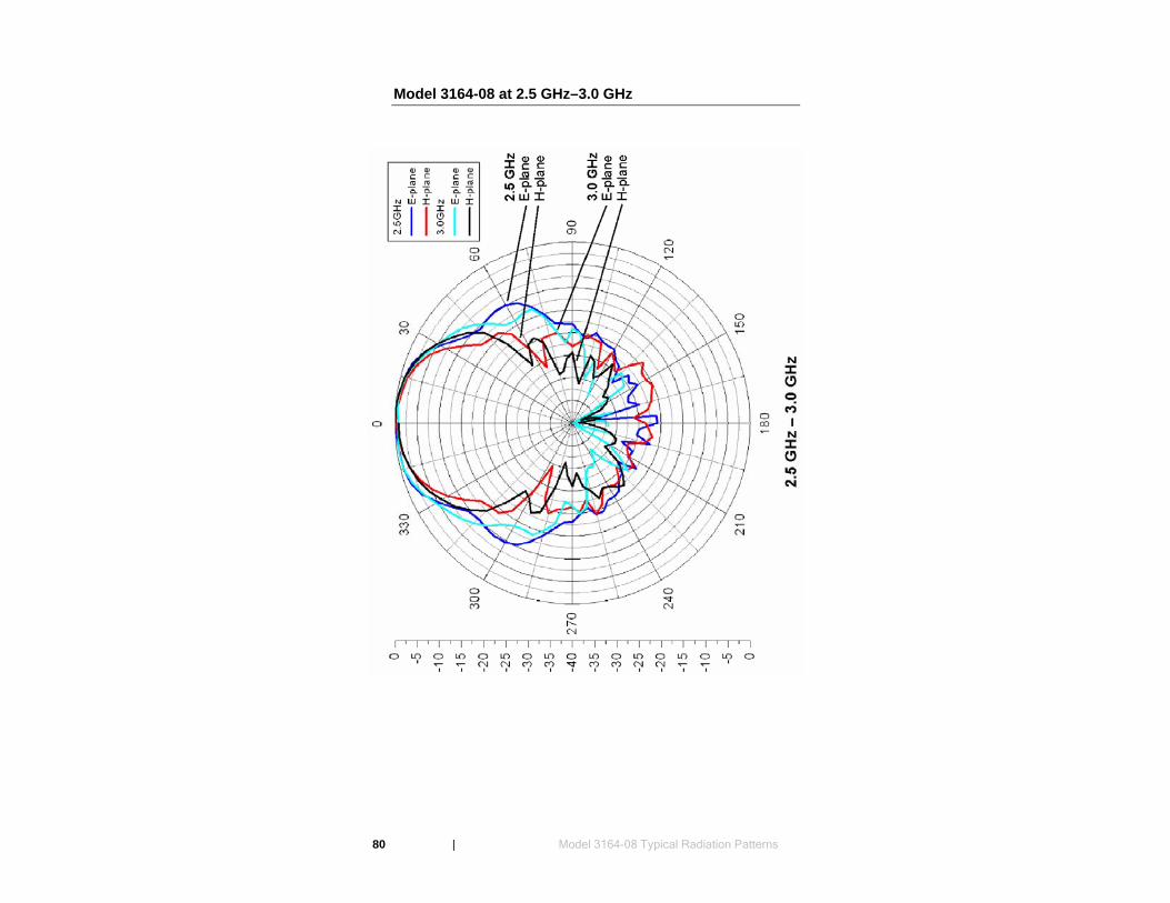
Model 3164-08 at 2.5 GHz–3.0 GHz
80 | Model 3164-08 Typical Radiation Patterns
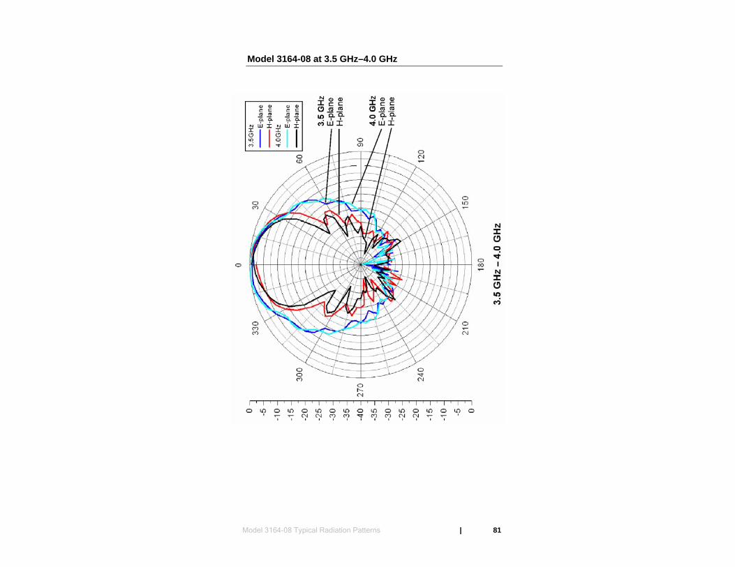
Model 3164-08 at 3.5 GHz–4.0 GHz
Model 3164-08 Typical Radiation Patterns | 81
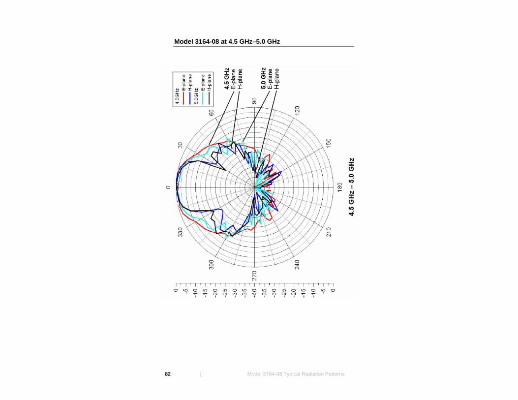
Model 3164-08 at 4.5 GHz–5.0 GHz
82 | Model 3164-08 Typical Radiation Patterns
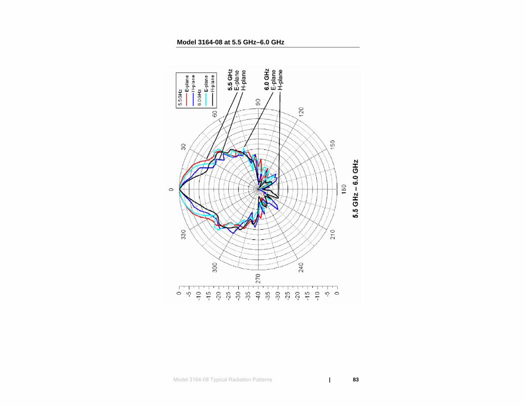
Model 3164-08 at 5.5 GHz–6.0 GHz
Model 3164-08 Typical Radiation Patterns | 83
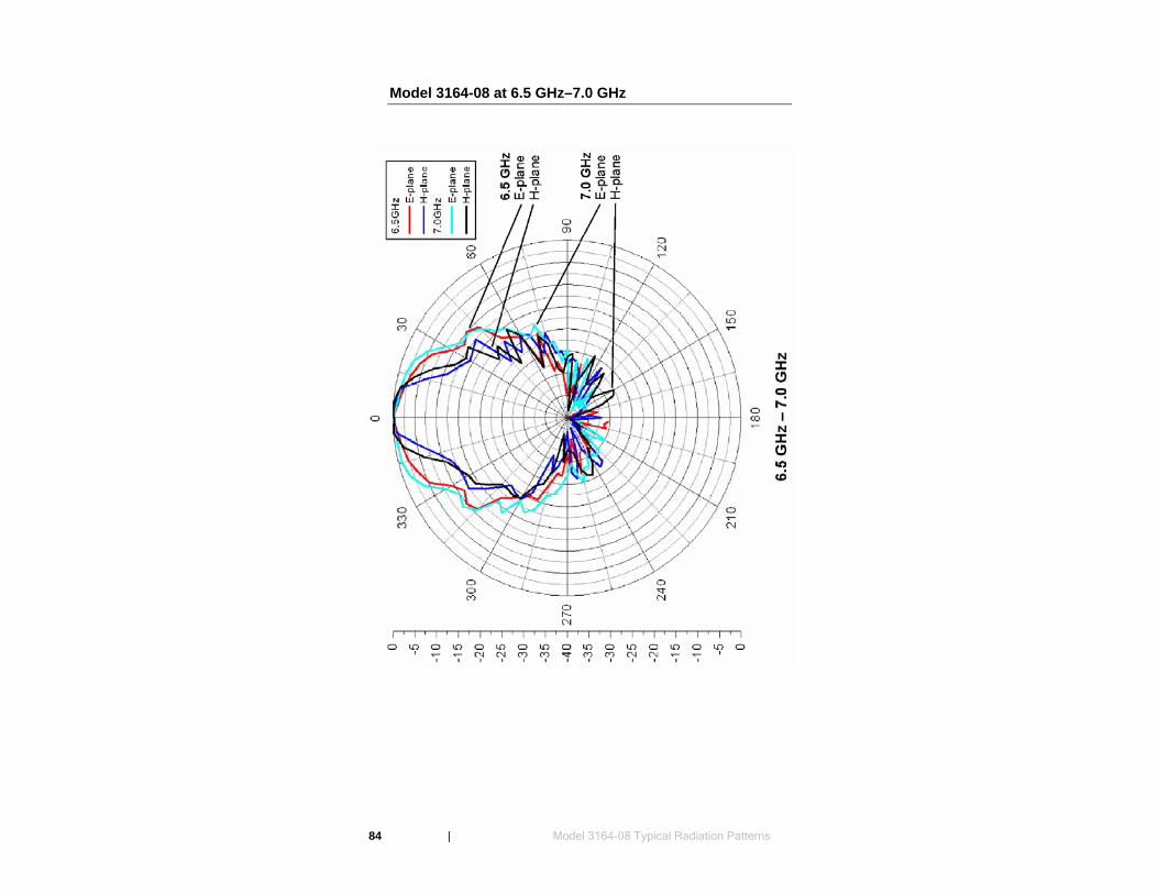
Model 3164-08 at 6.5 GHz–7.0 GHz
84 | Model 3164-08 Typical Radiation Patterns
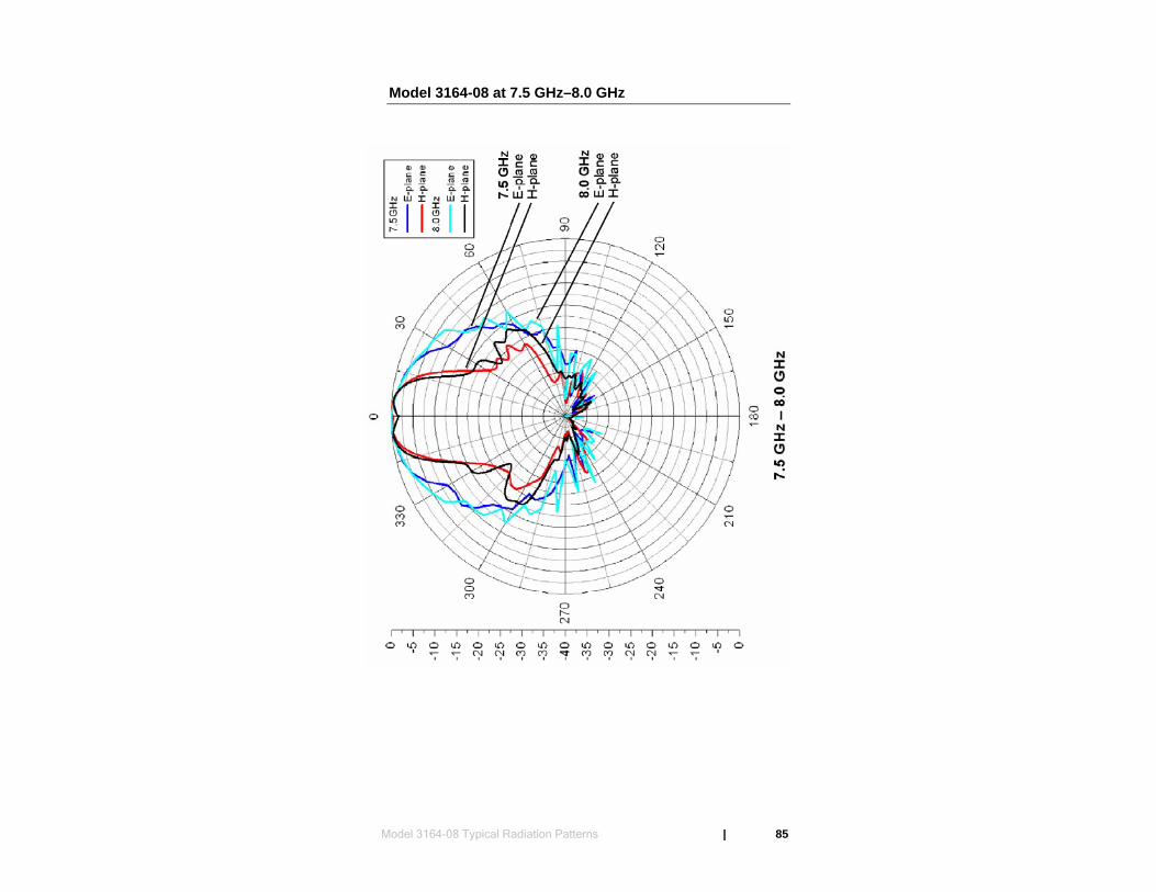
Model 3164-08 at 7.5 GHz–8.0 GHz
Model 3164-08 Typical Radiation Patterns | 85
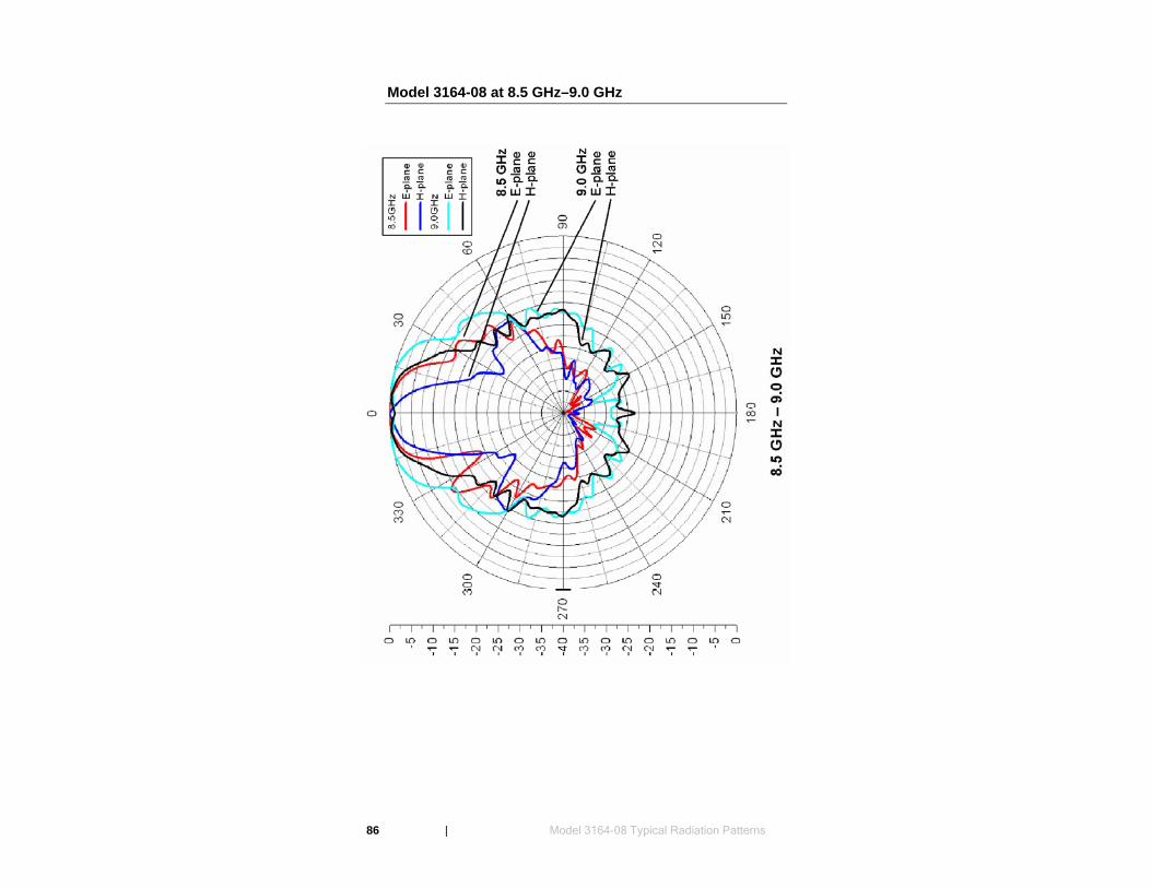
Model 3164-08 at 8.5 GHz–9.0 GHz
86 | Model 3164-08 Typical Radiation Patterns
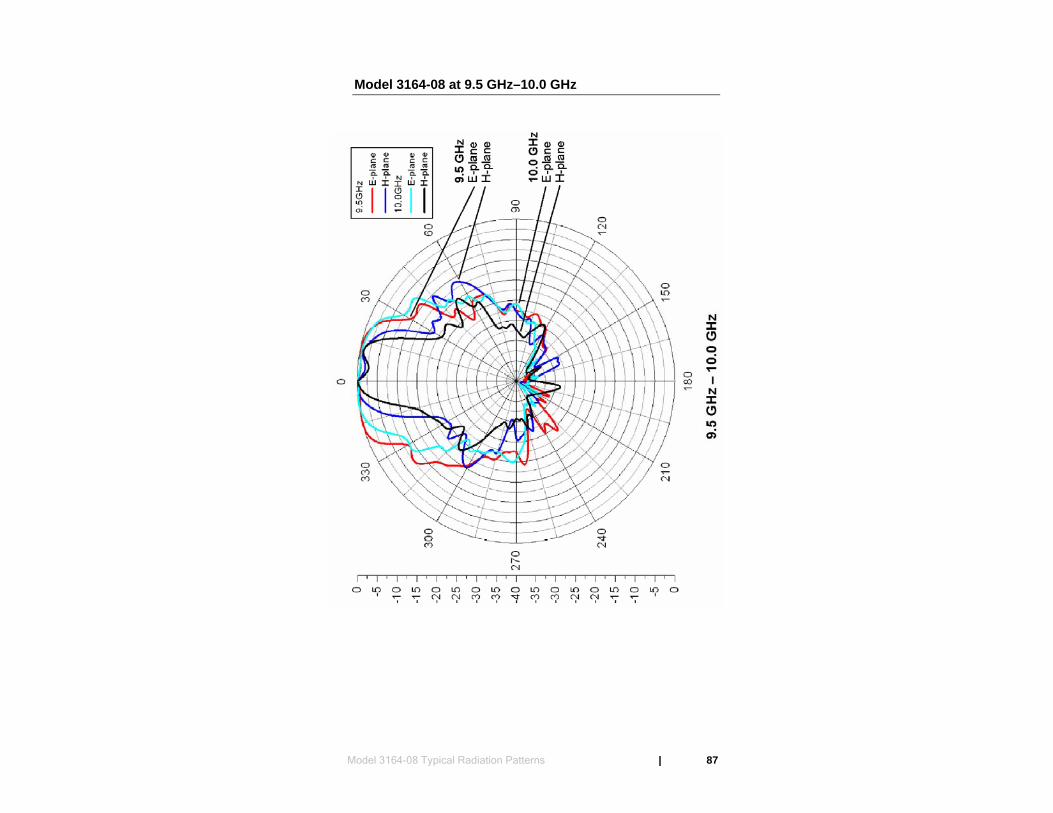
Model 3164-08 at 9.5 GHz–10.0 GHz
Model 3164-08 Typical Radiation Patterns | 87

This page intentionally left blank.
88 | Model 3164-08 Typical Radiation Patterns
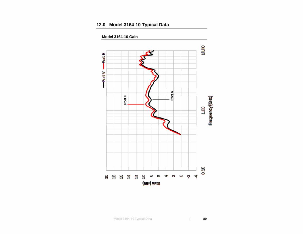
12.0 Model 3164-10 Typical Data
Model 3164-10 Gain
Model 3164-10 Typical Data | 89

Model 3164-10 VSWR
90 | Model 3164-10 Typical Data
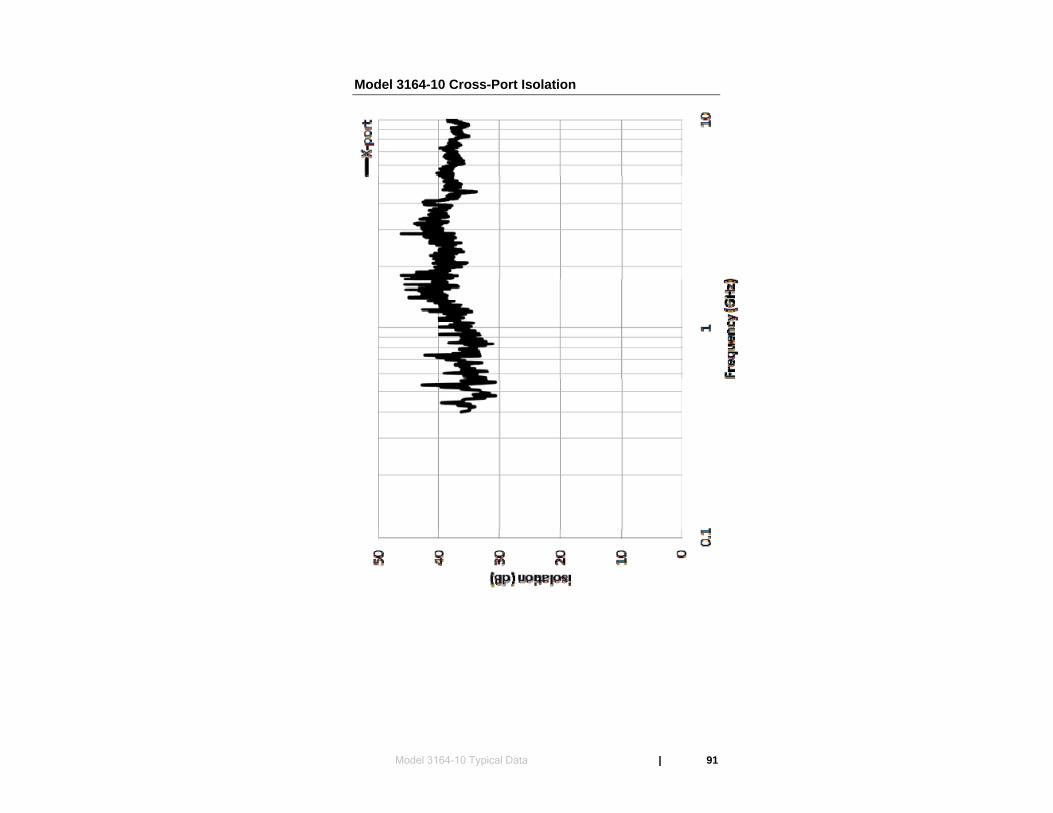
Model 3164-10 Cross-Port Isolation
Model 3164-10 Typical Data | 91

This page intentionally left blank.
92 | Model 3164-10 Typical Data
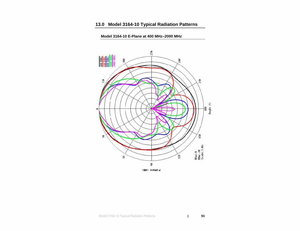
13.0 Model 3164-10 Typical Radiation Patterns
Model 3164-10 E-Plane at 400 MHz–2000 MHz
Model 3164-10 Typical Radiation Patterns | 93

Model 3164-10 H-Plane at 400 MHz–2000 MHz
94 | Model 3164-10 Typical Radiation Patterns
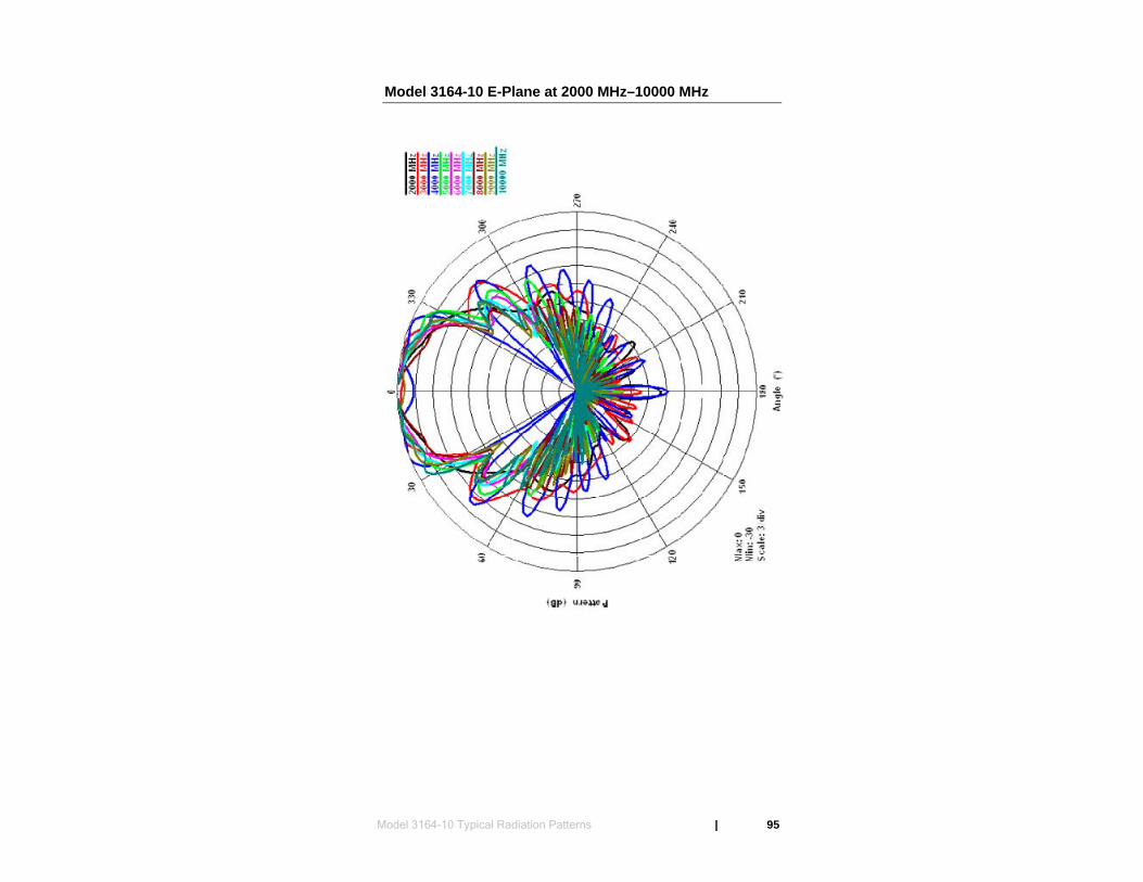
Model 3164-10 E-Plane at 2000 MHz–10000 MHz
Model 3164-10 Typical Radiation Patterns | 95
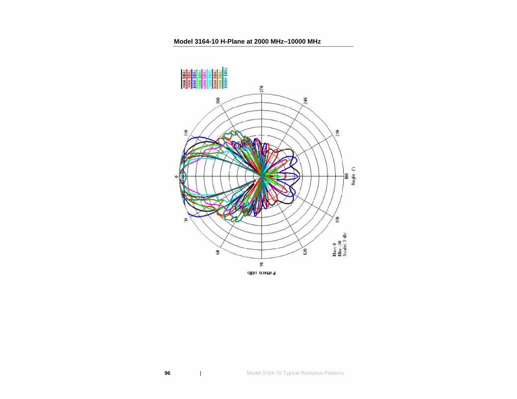
96 | Model 3164-10 Typical Radiation Patterns
Model 3164-10 H-Plane at 2000 MHz–10000 MHz
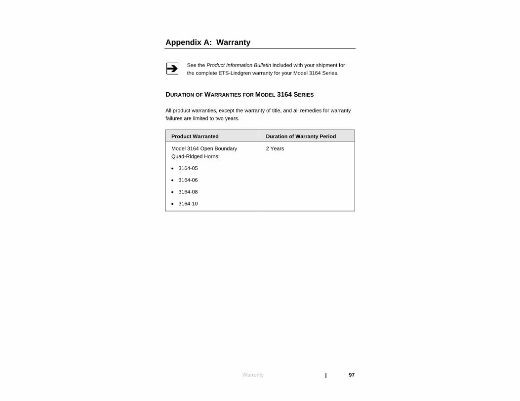
Appendix A: Warranty
See the Product Information Bulletin included with your shipment for the complete ETS-Lindgren warranty for your Model 3164 Series.
DURATION OF WARRANTIES FOR MODEL 3164 SERIES
All product warranties, except the warranty of title, and all remedies for warranty failures are limited to two years.
Product Warranted Duration of Warranty Period
Model 3164 Open Boundary Quad-Ridged Horns:
• 3164-05
• 3164-06
• 3164-08
• 3164-10
2 Years
Warranty | 97